US11726218B2 - Methods and systems for synchronizing backscatter signals and wireless transmission signals in x-ray scanning - Google Patents
Methods and systems for synchronizing backscatter signals and wireless transmission signals in x-ray scanningDownload PDFInfo
- Publication number
- US11726218B2 US11726218B2US17/659,627US202217659627AUS11726218B2US 11726218 B2US11726218 B2US 11726218B2US 202217659627 AUS202217659627 AUS 202217659627AUS 11726218 B2US11726218 B2US 11726218B2
- Authority
- US
- United States
- Prior art keywords
- signal
- detector
- transmission
- ray
- backscatter
- Prior art date
- Legal status (The legal status is an assumption and is not a legal conclusion. Google has not performed a legal analysis and makes no representation as to the accuracy of the status listed.)
- Active
Links
Images


Classifications
- G—PHYSICS
- G01—MEASURING; TESTING
- G01T—MEASUREMENT OF NUCLEAR OR X-RADIATION
- G01T7/00—Details of radiation-measuring instruments
- G—PHYSICS
- G01—MEASURING; TESTING
- G01T—MEASUREMENT OF NUCLEAR OR X-RADIATION
- G01T1/00—Measuring X-radiation, gamma radiation, corpuscular radiation, or cosmic radiation
- G01T1/16—Measuring radiation intensity
- G01T1/20—Measuring radiation intensity with scintillation detectors
- G01T1/208—Circuits specially adapted for scintillation detectors, e.g. for the photo-multiplier section
- G—PHYSICS
- G01—MEASURING; TESTING
- G01T—MEASUREMENT OF NUCLEAR OR X-RADIATION
- G01T1/00—Measuring X-radiation, gamma radiation, corpuscular radiation, or cosmic radiation
- G01T1/16—Measuring radiation intensity
- G01T1/1606—Measuring radiation intensity with other specified detectors not provided for in the other sub-groups of G01T1/16
- G—PHYSICS
- G01—MEASURING; TESTING
- G01V—GEOPHYSICS; GRAVITATIONAL MEASUREMENTS; DETECTING MASSES OR OBJECTS; TAGS
- G01V5/00—Prospecting or detecting by the use of ionising radiation, e.g. of natural or induced radioactivity
- G01V5/20—Detecting prohibited goods, e.g. weapons, explosives, hazardous substances, contraband or smuggled objects
- G01V5/22—Active interrogation, i.e. by irradiating objects or goods using external radiation sources, e.g. using gamma rays or cosmic rays
- G01V5/222—Active interrogation, i.e. by irradiating objects or goods using external radiation sources, e.g. using gamma rays or cosmic rays measuring scattered radiation
- G—PHYSICS
- G21—NUCLEAR PHYSICS; NUCLEAR ENGINEERING
- G21K—TECHNIQUES FOR HANDLING PARTICLES OR IONISING RADIATION NOT OTHERWISE PROVIDED FOR; IRRADIATION DEVICES; GAMMA RAY OR X-RAY MICROSCOPES
- G21K1/00—Arrangements for handling particles or ionising radiation, e.g. focusing or moderating
- G21K1/02—Arrangements for handling particles or ionising radiation, e.g. focusing or moderating using diaphragms, collimators
- G21K1/04—Arrangements for handling particles or ionising radiation, e.g. focusing or moderating using diaphragms, collimators using variable diaphragms, shutters, choppers
- G21K1/043—Arrangements for handling particles or ionising radiation, e.g. focusing or moderating using diaphragms, collimators using variable diaphragms, shutters, choppers changing time structure of beams by mechanical means, e.g. choppers, spinning filter wheels
Definitions
- the present specificationrelates to systems and methods of wirelessly coupling detectors to X-ray scanners and, in particular, wirelessly coupling a transmission detector panel to a backscatter system.
- Scanning devicesare well known which use a variety of sensing methods to detect concealed materials and objects. These scanning devices include transmission X-ray imaging systems, Compton scatter-based backscatter imaging systems, chemical sniffing trace detection equipment, thermal imaging camera systems and so on. Such scanning devices may be used alone or in combination to provide a comprehensive level of security. However, such devices tend either to be large and expensive (e.g. transmission X-ray imaging systems) or insensitive to carefully hidden materials (e.g. trace detection equipment and camera systems) which means that their utility is restricted to certain high throughput situations such as sea ports and land borders, airport checkpoints and other areas of the type.
- Scatter imagingin which the X-rays scattered (typically in a general backward direction) by a material, offers several unique inspection capabilities and operational features. Scatter imaging allows images to be obtained even when the imaged object is accessible from only one side. Moreover, since the scatter signal falls off rapidly with increasing depth into the object, backscatter images effectively represent a “slice” of the object characteristic of the side nearest to the X-ray source, thereby reducing problems of image clutter that typically confound transmission images.
- the Compton effectwhich dominates X-ray scatter in certain energy ranges, dominates the interaction of x-rays with dense low-atomic-number (low-Z) materials.
- Narcotic drugstend to produce bright signatures in a backscatter image, as do organic explosives, making backscatter imaging a useful imaging modality for bomb or drug detection. Further, in scatter detection, alignment requirements of the x-ray beam with detectors or collimation devices are less exacting, as compared to transmission imaging, thereby enabling rapid deployment in a wide range of inspection scenarios.
- a thin “pencil beam” of X-raysis rapidly and repetitively swept through a source-centered, vertically-oriented “fan” of beam paths that are arranged to intercept the object under inspection.
- the objectis moved at a constant, yet slower speed along a path perpendicular to the fan, on a horizontally moving conveyor belt, for example.
- the pencil beamtraverses the object in point-by-point raster fashion, and the entire object is scanned as it passes through the fan plane over a period ranging from a few seconds to a few minutes depending upon the length of the object.
- the total scan timemay be seconds to minutes in duration
- the actual exposure time of any part of the scanned objectis only the brief time it takes for the pencil beam to sweep across a given pixel. That exposure time is typically in the range of microseconds, depending on the design and the application, and yields an entrance exposure to the scanned object that constitutes a low dose to the object. This also means that there is little radiation available to scatter into the environment, therefore the doses to operators and other bystanders is correspondingly low.
- U.S. Pat. No. 10,168,445assigned to Applicant of the present specification, discloses a compact, light-weight, portable and hand-held system or device that can be maneuvered to reach relatively inaccessible locations and scan behind concealing barriers that are otherwise opaque against chemical and optical probes.
- the disclosed systemis a compact, hand-held device that uses the principle of X-ray backscatter to provide immediate feedback to an operator about the presence of scattering and absorbing materials, items or objects behind concealing barriers irradiated by ionizing radiation, such as X-rays.
- Feedbackis provided in the form of a changing audible tone whereby the pitch or frequency of the tone varies depending on the type of scattering material, item or object.
- the operatorobtains a visual scan image on a screen by scanning the beam around a suspect area or anomaly.
- the handheld devicecomprises one or more BX detectors while a TX detector is placed at a distance from the scanner and is in wired communication with the handheld device.
- the transmission detectoris coupled with the scanner by using power and signal cables in order to synchronize the BX detector of the scanner and the transmission detector.
- an X-ray scannercomprising: a housing; an X-ray source positioned in the housing; a backscatter detector physically coupled to the housing system; a transmission detector adapted to be positioned remote from the housing and not physically coupled to the housing, wherein the transmission detector is adapted to generate a signal when X-rays emitted by the X-ray source impinge on a surface of the transmitter detector after passing through an object being scanned and wherein the transmission detector further comprises a wireless transmitter for transmitting the signal; and a controller physically coupled to the housing and adapted to control an operation of the X-ray source, wherein the controller comprises a receiver configured to receive the wirelessly transmitted signal from the transmission detector, wherein the transmitter and the receiver operate in a frequency range of 6 Mhz to 6 Ghz.
- the transmitteris positioned on an external surface of the transmission detector.
- the transmission detectorfurther comprises a pre-amplifier coupled with the at least one photomultiplier tube and is adapted to amplify the signal.
- the X-ray scanneris configured to be hand-held.
- the transmitterfurther comprises an amplitude modulator adapted to modulate an amplitude of the signal before transmitting the signal.
- the controllercomprises a buffer and wherein the receiver comprises an amplitude demodulator for demodulating the amplitude of the transmitted signal before transmitting the signal to the buffer.
- the transmitterpolarizes the signal before transmission for avoiding interference with one or more signals having a same frequency as the signal being transmitted, wherein the polarization is one of: a horizontal polarization or a vertical polarization.
- the receiveris positioned on an external surface of the transmission detector.
- an X-ray scannercomprising: a housing; an X-ray source positioned in the housing; a rotating collimator positioned proximate the X-ray source and configured to collimate X-ray beams emanating from the X-ray source; a backscatter detector physically coupled to the housing system; a transmission detector adapted to be positioned remote from the housing and not physically coupled to the housing, wherein the transmission detector is adapted to generate a signal when the X-ray beams emitted by the X-ray source impinge on a surface of the transmitter detector after passing through an object being scanned and wherein the transmission detector further comprises a wireless transmitter for transmitting the signal; and a controller physically coupled to the housing and adapted to control an operation of the X-ray source, wherein the controller comprises a receiver configured to receive the wirelessly transmitted signal from the transmission detector and wherein the controller further comprises a buffer coupled to the receiver and configured to store data indicative of the signal for a predefined period of time,
- the transmission detectorcomprises a plurality of wavelength shifting fibers (WSF) coupled with at least one photomultiplier tube.
- WSFwavelength shifting fibers
- the X-ray scannerfurther comprises an analog to digital (A/D) converter coupled to the transmission detector and adapted to convert the signal to a digital signal, wherein an operation of the A/D converter is synchronized using time data from a first clock coupled with the transmission detector.
- A/Danalog to digital
- the transmitter coupled with the transmission detectoris adapted to transmit the signal and time data from the first clock.
- the receiver coupled with the controlleris adapted to receive the signal and time data from the first clock.
- the predefined period of timeis a function of the time data and the position of the rotating collimator.
- the controllercomprises a digital to analog (D/A) converter coupled with the buffer and adapted to convert the buffered signal to an analog signal after the expiry of the predefined period of time, wherein an operation of the D/A converter is synchronized using time data from a second clock coupled with the buffer, and wherein the time data of the second clock is synchronized using time data of the first clock.
- D/Adigital to analog
- the transmitteris positioned on an external surface of the transmission detector.
- the transmission detectorfurther comprises a pre-amplifier coupled with at least one photomultiplier tube and is adapted to amplify the signal.
- the X-ray scanneris configured to be hand-held.
- the transmitterfurther comprises an amplitude modulator adapted to modulate an amplitude of the signal before transmitting the signal.
- time data the first clock and time data of the second clockare synchronized using at least one of GPS based clock system or a temporary hardwire connection.
- the predefined period of timeis a function of a time taken for one rotation of the collimator.
- the controllercomprises a digital to analog (D/A) converter coupled with the buffer and adapted to convert the buffered signal to an analog signal at a delay equal to a time taken for one rotation of the collimator wheel of the scanner.
- D/Adigital to analog
- the transmitteris configured to polarize the signal before wirelessly transmitting the signal to avoid interfering with one or more signals having a same frequency as the signal being transmitted
- the polarizationis at least one of a horizontal polarization such that an electrical field of the signal oscillates in a horizontal plane, a vertical polarization such that the electrical field of the signal oscillates in a vertical plane, or an angled plane such that the electrical field of the signal oscillates in a plane that has a non-zero angle relative to the horizontal plane and the vertical plane.
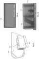
- FIG. 1is a perspective view of a hand-held portable scanning device that may be connected wirelessly with a transmission detector, in accordance with an embodiment of the present specification
- FIG. 2is a vertical cross-sectional view of the hand-held portable scanning device of FIG. 1 ;
- FIG. 3illustrates a block diagram of a flying-spot X-ray inspection system, in accordance with an embodiment of the present specification
- FIG. 4is a perspective view of a hand-held portable scanning device that may be connected wirelessly with a transmission detector, in accordance with an embodiment of the present specification
- FIG. 5illustrates a detector panel placed in the path of a direct beam of scanning radiation emitted by a small portable scanner being used to scan an object, in accordance with an embodiment of the present specification
- FIG. 6illustrates a backscatter image obtained by using the scanner of FIG. 5 , in accordance with an embodiment of the present specification
- FIG. 7 Aillustrates a transmission image obtained by a built-in detector of a hand-held scanner by using the detector panel as shown in FIG. 5 , in accordance with an embodiment of the present specification
- FIG. 7 Billustrates transmission images of a gun placed behind steel walls of different thickness obtained by using the detector panel shown in FIG. 5 ;
- FIG. 7 Cis a diagrammatic representation of a wavelength shifting sheet (WSS) detector as used in a transmission mode with a flying spot X-ray imager, in an embodiment of the present specification;
- WSSwavelength shifting sheet
- FIG. 7 Dis a flow diagram representing the steps of using an WSS detector in a transmission mode with a flying spot X-ray imager, in accordance with an embodiment of the present specification
- FIG. 8 Aillustrates a diagrammatical representation of a wavelength shifting fiber (WSF) detector panel, in accordance with another embodiment of the present specification
- FIG. 8 Billustrates the WSF detector panel of FIG. 8 A , in accordance with an embodiment of the present specification
- FIG. 8 Cillustrates a scan image of a car wheel obtained by using a transmission detector
- FIG. 8 Dillustrates a scan image of the car wheel by using a backscatter detector
- FIG. 8 Eillustrates a portable/hand held scanner and a transmission detector panel that may be used to obtain the images of FIGS. 8 C and 8 D ;
- FIG. 9illustrates a collimator wheel of a portable/handheld scanner, in accordance with an embodiment of the present specification.
- FIG. 10illustrates a block diagram of circuitry employed to implement analog wireless communication between a transmission detector panel and a portable/handheld scanner, in accordance with an embodiment of the present specification
- FIG. 11illustrates a block diagram of circuitry employed to implement digital wireless communication between a transmission detector panel and a portable/handheld scanner, in accordance with an embodiment of the present specification
- FIG. 12 Ashows multiple detectors folding out of a hand-held scanner, in a stored condition, in accordance with an embodiment of the present specification
- FIG. 12 Bshows multiple detectors folding out of a hand-held scanner, in a deployed condition, in accordance with an embodiment of the present specification
- FIG. 12 Cillustrates the imaging system of FIG. 13 A connected with a transmission detector panel, in accordance with an embodiment of the present specification
- FIG. 13 Ashows a backscatter unit that, by virtue of WSF detectors in accordance with the present specification, may be slid under a vehicle for under-chassis inspection;
- FIG. 13 Bshows a backscatter unit that, by virtue of WSF detectors in accordance with the present specification, may be slid under a vehicle for under-chassis inspection;
- FIG. 13 Cillustrates an image of the underside of a vehicle obtained by using a portable backscatter scanning system, in accordance with an embodiment of the present specification.
- FIG. 13 Dillustrates an image of the underside of a vehicle obtained by using a portable backscatter scanning system wirelessly connected to a transmission detector panel, in accordance with an embodiment of the present specification.
- the present specificationprovides a transmission detector panel that may be coupled wirelessly to a portable/handheld scanner. While aspects of the present specification may be described herein with reference to particular types of handheld scanners and transmission detectors, the system and method described in detail herein may be used to couple various types of scanners wirelessly with various types of transmission detectors.
- the optical coupling of scintillator material to optical waveguides, and, more particularly, to wavelength-shifting fibersadvantageously enables objectives including those peculiar to the demands of X-ray scatter detection.
- imageshall refer to any unidimensional or multidimensional representation, whether in tangible or otherwise perceptible form, or otherwise, whereby a value of some characteristic (such as fractional transmitted intensity through a column of an inspected object traversed by an incident beam, in the case of X-ray transmission imaging) is associated with each of a plurality of locations (or, vectors in a Euclidean space, typically R2) corresponding to dimensional coordinates of an object in physical space, though not necessarily mapped one-to-one thereto.
- An imagemay comprise an array of numbers in a computer memory or holographic medium.
- imagingrefers to the rendering of a stated physical characteristic in terms of one or more images.
- the term “thickness,” as applied to a scintillation detector,shall represent the mean extent of the detector in a dimension along, or parallel to, a centroid of the field of view of the detector.
- the term area, as applied to a detector, or, equivalently, the term “active area”shall refer to the size of the detector measured in a plane transverse to centroid of all propagation vectors of radiation within the field of view of the detector.
- the term “large-area detector”shall refer to any single detector, or to any detector module, subtending an opening angle of at least 30° in each of two orthogonal transverse directions as viewed from a point on an object undergoing inspection, equivalently, characterized by a spatial angle of at least ⁇ steradians.
- a “conveyance”shall be any device characterized by a platform borne on ground-contacting members such as wheels, tracks, treads, skids, etc., used for transporting equipment from one location to another.
- a “computing device”includes an input/output controller, at least one communication interface and a system memory and is used to operate the handheld scanner of the present specification.
- the system memoryincludes at least one random access memory (RAM) and at least one read-only memory (ROM). These elements are in communication with a central processing unit (CPU) to enable operation of the computing device.
- the computing devicemay be a conventional standalone computer or alternatively, may be contained within the system as described in the present specification.
- execution of a plurality of sequences of programmatic instructions or codewhich are stored in one or more non-volatile memories, enable or cause the CPU of the computing device to perform various functions and processes such as, for example, performing image reconstruction for display on a screen.
- hard-wired circuitrymay be used in place of, or in combination with, software instructions for implementation of the processes of systems and methods described in this application. Thus, the systems and methods described are not limited to any specific combination of hardware and software.
- a controlleris included in the handheld scanner housing and is used to control the operation of the X-ray source and the routing, transmission, processing, and/or storage of the detection signals.
- the controlleris physically coupled to the housing of the handheld scanner and is adapted to control an operation of the X-ray source.
- the controllercomprises a receiver configured to receive the wirelessly transmitted signal from a transmission detector, wherein the transmitter and the receiver operate in a frequency range of 400-480 MHz.
- the controlleris physically coupled to the housing and adapted to control an operation of the X-ray source, whereby the controller comprises a receiver configured to receive the wirelessly transmitted signal from the transmission detector and whereby the controller further comprises a buffer coupled to the receiver and configured to store data indicative of the signal for a predefined period of time.
- the predefined period of timeis a function of at least one of a time when the signal is generated, a position of the rotating collimator, a time when the signal is received, or a time when a signal from the backscatter detector is generated.
- each of the words “comprise” “include” and “have”, and forms thereof,are not necessarily limited to members in a list with which the words may be associated. It should be noted herein that any feature or component described in association with a specific embodiment may be used and implemented with any other embodiment unless clearly indicated otherwise.
- FIG. 1is a perspective view of a hand-held portable scanning device that may be wirelessly connected to a transmission detector, in accordance with an embodiment of the present specification.
- FIG. 2is a vertical cross-sectional view of the hand-held portable scanning device of FIG. 1 .
- an exemplary hand-held portable X-ray based scanning system 100that may be connected wirelessly to a transmission detector panel, is shown.
- the hand-held portable X-ray based scanning system 100also referred to as an imaging system or device, may be used for screening objects such as, but not limited to, baggage, containers/boxes, and other similar items for threat materials, items or people concealed therein.
- the system 100is configured in the form of an enclosure or housing 105 having an upper surface 110 , a base (not visible in FIG. 1 , but opposite, and substantially parallel to, the upper surface 110 ), a front surface 114 , a rear surface (not visible in FIG. 1 , but opposite, and parallel to, the front surface 114 ), a first side 117 , and a second side (not visible in FIG. 1 , but opposite, and parallel to, the first side 117 ).
- the size and weight of system 100is optimized for enabling an operator to conveniently hold and maneuver the housing 105 while scanning an object under inspection.
- the housing 105is in the form of a first cuboid 125 (bearing the front surface 114 ) that tapers, along a central longitudinal axis 130 , into a second cuboid 135 culminating in the rear surface.
- a height ‘H’ of the first cuboid 125is greater than a height ‘h’ of the second cuboid 135 .
- the shape of the housing 105can be cylindrical, conical, pyramidal or any other suitable shape in various embodiments.
- housing 105is in the form of a first cuboid 125 that attaches, at a back face and along a central longitudinal axis 130 , to a first trapezoidal prism 118 that tapers and, at its back face, attaches the second trapezoidal prism 135 .
- At least one handle 112is provided on, for example, the upper surface 110 to allow the operator to hold the housing 105 conveniently in one or both hands and manipulate the device 100 to point the front surface 114 towards and at different regions on the object under inspection.
- one or more handlesare provided on one or more areas or regions such as the upper surface 110 , the base, the first side 118 and/or the second side so that single-handed or two-handed operation of device 100 is facilitated, depending on what is easiest for the operator.
- the housing 105comprises an X-ray tube 140 wherein a corresponding anode 141 , also referred to as a target, emits a spatially localized X-ray beam 145 through an opening 142 , also referred to as an aperture.
- At least one shield 143formed of an X-ray absorptive material, such as tungsten or uranium, surrounds and encloses anode 141 to absorb stray radiation emitted from anode 141 .
- Opening 142defined through shield 143 , is provided with a size and thickness which enables opening 142 to act as a collimator in forming or shaping and limiting the X-ray radiation, emitted from anode 141 , into a shaped beam of X-rays 145 .
- X-ray beam 145is shaped into a pencil beam.
- a cathode and heater filament assembly(enclosed within housing 105 ) is held at a substantial potential difference (using a chargeable battery also enclosed within the housing 105 ) with reference to anode 141 by a kilovolt power supply (wrapped around at least one tube shielding 143 , in one embodiment).
- This potential differencecauses thermionic electrons freed by the heated cathode (heated using the heater filament) to be directed and drawn to anode 141 at sufficiently high velocity to result in the generation of X-ray beam 145
- An X-ray beam 145emerges through an opening 144 at the center of front surface 114 of housing 105 , in a direction substantially perpendicular to front surface 114 .
- At least one X-ray backscatter detector 150is positioned adjacent to and behind front surface 114 in order to maximize detected backscatter signal.
- Scatter imaging in which the X-rays are scattered by a materialoffers several unique inspection capabilities and operational features. Scatter imaging allows images to be obtained even when the imaged object is accessible from only one side. Moreover, since the scatter signal falls off quite rapidly with increasing depth into the object, backscatter images effectively represent a “slice” of the object characteristic of the side nearest to the X-ray source, thereby reducing problems of image clutter that may confound transmission images.
- the Compton effectwhich dominates X-ray scatter in the energy range typically employed in accordance with the present invention, dominates the interaction of X-rays with dense low-atomic-number (low-Z) materials.
- Narcotic drugstend to produce the bright signatures in a backscatter image, as do organic explosives, making backscatter imaging a useful imaging modality for bomb or drug detection.
- alignment requirements of the x-ray beam with detectors or collimation devicesare less exacting than for transmission imaging thereby enabling rapid deployment in a wide range of inspection scenarios.
- Flying-spot technologymakes possible the acquisition of images using detectors specifically positioned to collect the scattered X-rays.
- a thin “pencil beam” of X-raysis rapidly and repetitively swept through a source-centered, vertically-oriented “fan” of beam paths that are arranged to intercept the object under inspection.
- the objectis moved at a constant, slower speed along a path perpendicular to the fan, on a horizontally moving conveyor belt for example.
- the pencil beamis made to traverse the object in point-by-point raster fashion, and the entire object is scanned as it passes through the fan plane over a period ranging from a few seconds to a few minutes depending upon the length of the object.
- the total scan timemay be seconds to minutes in duration
- the actual exposure time of any part of the scanned objectis only the brief time it takes for the pencil beam to sweep across a given pixel. That exposure time is typically in the range of microseconds, depending on the design and the application, and yields an entrance exposure to the scanned object that constitutes a low dose to the object also means that there is little radiation available to scatter into the environment, so the doses to operators and other bystanders is correspondingly low.
- FIG. 3illustrates a block diagram of a flying-spot X-ray inspection system, in accordance with an embodiment of the present specification.
- the components of the flying-spot X-ray inspection system shown in FIG. 3may be enclosed in a housing of a handheld portable inspection system.
- System 180comprises an X-ray source 30 including an X-ray tube 32 and a chopper 34 .
- source energiesare typically below 250 keV thus the chopper 34 may be smaller than employed in systems in which higher-energy X-rays are employed.
- Chopper 34may be a rotating perforated hub, or a wheel with transmitting spokes, or any number of means, known in the art, for generation of flying spot beams.
- chopper 34comprises a rotating hoop, with apertures 36 and 38 , and emits a pencil beam of X-rays, thereby enabling inspection of objects, possibly on either side of the inspection system.
- X-raysemerge from the currently illuminated channel as a pencil beam that is swept across an object undergoing inspection as the wheel 34 rotates.
- the dimensions of the X-ray beamtypically govern the resolution of a system such as the one depicted.
- Aperture 36may have various shapes, and may be circular or rectangular, and may be more specifically tailored.
- Other X-ray generation approachesmay be used to produce a similar sweeping pencil beam, such as spinning discs with elongated slits, wheels with hollow spokes, are alternate embodiments.
- Detector modules 182are typically enclosed within a housing of a handheld portable inspection system. In an embodiment, the detectors 182 may also be carried outside the housing for particular applications within the scope of the present invention. Detector modules contain detectors for detecting penetrating radiation from source 30 that has interacted with, and scattered from, contents of the inspected object.
- detector modules 182comprise transmission detectors placed behind an object being irradiated with the X-ray beam (such that the object is between the X-ray source and the detector), for receiving a transmission beam comprising X-rays that are transmitted through the object.
- the received beamis absorbed by a scintillator layer of the detector and subsequently transmitted to a photomultiplier tube for detection, which in turn transmits the detected data to a data acquisition system for processing.
- separate, large-area detectorsare deployed adjacent to the beam plane on the X-ray source side of the scanned object, and with their active surfaces oriented toward the scanned object. These detectors need only provide a large solid angle for collection of scattered radiation; no critical alignments are required. In this location these detectors respond to x-rays which are scattered generally back toward the source from the object.
- the output from backscatter detectors 182are switched to a pulse counting circuit during a fraction of the operating cycle in which the source of X-ray irradiation is switched off. During this period, individual neutrons or gamma rays can be detected and analyzed.
- the efficiency of the backscatter detectors of an X-ray inspection system for detecting neutrons or gamma rayhas been discussed above.
- Detectors 182may also be sensitive to both natural emission and emissions generated by threat materials.
- a detectoris having high efficiency for detecting thermal and epi-thermal (intermediate energy, typically 1 10.sup.4 eV) neutrons is employed.
- the detectoruses the scintillator Gd 2 O 2 S, commonly known, and referred to herein, as “gadox,” to stop both neutrons and the photons.
- Gd 2 O 2 Scommonly known, and referred to herein, as “gadox”
- X-ray-induced scintillations from the gadox in the visible portion of the spectrumare then detected, typically by photomultipliers or photodiodes.
- Alternative scintillators, such as LiF, for example, with high cross sections for detecting thermal and epithermal neutronsare also within the scope of the present invention.
- the maximum energy of the X-rays produced by X-ray tube 32determines the ability of these X-rays to penetrate into the object under inspection i.e., the higher the maximum X-ray energy, the more penetration can be achieved.
- the higher the energy of the scattered X-ray photonthe more likely it is to escape through the object under inspection back to an X-ray detector 182 . Therefore, in accordance with an aspect it is desirable to have high X-ray energy to maximize depth of inspection within the object.
- FIG. 4illustrates another exemplary hand-held portable X-ray based scanning system 200 that may be connected wirelessly to a transmission detector panel, in accordance with an embodiment of the present specification.
- the hand-held portable X-ray based scanning system 200also referred to as an imaging system or device, may be used for screening objects such as, but not limited to, baggage, containers/boxes, and other items for threat materials, items or people concealed therein.
- Components of system 200such as, a housing 205 , an upper surface 210 , a base, a handle 212 , a front surface 214 , a rear surface, a first side 218 , a second side, a first cuboid 225 , a central longitudinal axis 230 , and a second cuboid (or trapezoidal prism) 235 —are configured similar to corresponding components described above in context of FIGS. 1 - 3 . These components, and the associated variations, are not described herein as they have been described in detail above.
- the scanning system 200comprises single pixel backscatter detectors 250 .
- Penetrating radiation scattered by an object being imagedis detected by backscatter detectors 250 , wherein each single pixel detector may be coupled to a processor for forming a backscatter image of the object.
- Detectors 250may employ wavelength-shifting fiber coupling of scintillation, thereby allowing thin-profile detectors to be deployed outward from a folded configuration with respect to the housing 205 .
- Housing 205comprises an X-ray tube whose anode, also referred to as a target, emits a spatially localized X-ray beam 245
- a portable/handheld scannersuch as that shown in FIGS. 1 , 2 , 3 , 4 and 8 E comprises an internal backscatter detector (not visible in the figure).
- transmission detector panelsare used in conjunction with portable hand held scanners to obtain images of objects being scanned.
- the detector panelis designed for placement at any position relative to a portable/handheld scanner.
- the detector panelwhen the detector panel is placed in the path of a beam of radiation generated by an X-ray source, the detector panel acts as a transmission detector.
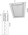
- FIG. 5illustrates a detector panel placed in the path of a beam of scanning radiation emitted by a small portable scanner being used to scan an object, in accordance with an embodiment of the present specification.
- detector panel 702is placed behind a concrete block 704 which is being scanned by a portable scanner comprising an X-ray source (not shown in the figure) such that the detector panel 702 is placed in a direct beam path of the radiation being emitted by said source.
- the concrete block 704houses a steel pipe bomb 706 (partially visible in FIG. 5 ) and a hand grenade (not visible in FIG. 5 ).
- FIG. 6illustrates a backscatter image obtained by using only the detector of FIG. 5 , in accordance with an embodiment of the present specification.
- a backscatter image 708 obtained by using only the built-in detectors of a hand held scannerdoes not show either the steel pipe bomb 706 or the hand grenade contained within the concrete block 704 .
- FIG. 7 Aillustrates a transmission image obtained by using a hand-held scanner and the detector panel 702 shown in FIG. 5 , in accordance with an embodiment of the present specification. As can be seen in FIG. 7 A , the transmission image 710 clearly shows a hand grenade 712 and the steel pipe bomb 706 contained within the concrete block 704 .
- FIG. 7 Billustrates transmission images of a gun placed behind steel walls of different thickness obtained by using the detector panel shown in FIG. 5 .
- Images 720 , 722 , 724 , 726illustrate the images of a gun placed behind 3.2 mm, 6.4 mm, 12.7 mm, and 19.1 mm of steel respectively.
- a challengeis that there is typically no pre-established physical configuration between the detector and the scanning source. If the position of the source relative to the detector is known/fixed, the location of impurities and irregularities in the detector may be fixed, and hence, any detected data could be automatically corrected for said irregularities. Specifically, the gain could be corrected (increased/decreased) to account for spots or lines due to issues in manufacturing of the scanner/detector.
- the relative configuration of the detector panel and the scanning sourceis changeable, making it difficult to predict precisely the location of non-uniformities in the scanning image.
- the non-uniformities that are inherent to the detector responsecannot be corrected using known gain correction methods.
- the signals received by using the detector as shown in FIG. 5will be raw and may include defects such as, but not limited to: gain non-uniformity due to variations in the X-ray absorption in scintillator; non-uniformity in the scintillator light production and propagation; and non-uniformity in light collection across the area of detector.
- the challengetherefore, is to create a detector panel which generates the same light output as a photo multiplier tube (PMT).
- PMTphoto multiplier tube
- a variabilityranging from 30% to 40% may be tolerated.
- a variability of 10% or lessis required.
- an X-ray detectorcomprising a screen fabricated from a scintillator material, such as phosphor, that is optically coupled, in optical contact or in physical communication with a wavelength-shifting sheet (WSS), which shifts light absorbed from the scintillator screen may be used as a transmission detector panel wirelessly connected to a handheld portable backscatter X-ray imaging system.
- the wavelength shifting sheetis coupled to a wavelength shifting fiber or sheet at the edge of the wavelength shifting sheet that is configured to collect a plurality of first shifted rays.
- the rays collected from the edgeare transmitted through to a photodetector, such as a photo multiplier tube (PMT).
- PMTphoto multiplier tube
- WSSWave Shifting Sheet
- WSFWave Shifting Fibers
- the WSS detectoris implemented as a transmission scan panel that can be used with any commercially available handheld scanning system such as, but not limited to, the MINI ZTM scanning system, and/or embodiments disclosed in U.S. Pat. No. 10,168,445, which is incorporated herein by reference, to provide a simultaneous secondary image.
- the detectorprovides a transmission image when placed directly behind an item being scanned, or an additional backscatter image when placed on the near side of the object being scanned.
- the secondary imageis displayed next to the standard Backscatter image on a display screen coupled with the MINI Z scanning system.
- the transmission scan panelis portable, light-weight, and connects to handheld scanning system with a simple, single cable connection.
- FIG. 7 Cis a diagrammatic representation of a WSS detector as used in a transmission mode with a flying spot X-ray imager, in an embodiment of the present specification.
- a flying spot X-ray imager 1702irradiates an object 1704 being inspected with a flying spot beam 1706 , as shown in the FIG. 7 C .
- a WSS detector 1708 placed behind the object 1704(such that the object 1704 is between the imager 1702 and the detector 1708 ), receives a transmission beam 1710 comprising X rays that are transmitted through the object 1704 .
- the beam 1710is absorbed by a scintillator layer (not shown in the FIG.) and shifted by one or more WS materials of the WSS detector 1708 as explained in the preceding sections.
- the shifted beamis transmitted to a photomultiplier tube 1712 for detection which in turn transmits the detected data to a data acquisition system (not shown in the FIG.) of the imager 1702 for processing.
- FIG. 7 Dis a flow diagram representing the steps of using an WSS detector in a transmission mode with a flying spot X-ray imager, in accordance with an embodiment of the present specification.
- an object under inspectionis irradiated with a flying spot X-rays, emanating from an X-ray imager.
- a transmission beamcomprising X rays that are transmitted through the object are received by a WSS detector placed behind the object (such that the object is positioned between the imager and the detector).
- the transmission beamis absorbed by a scintillator layer of the detector and emitted as corresponding light rays.
- the emitted light raysare shifted by one or more WS materials of the WSS detector.
- the shifted light raysare transmitted to a PMT for detection.
- the shifted light raysare converted to electrical signals by the photomultiplier tube.
- the electrical signalsare transmitted to a data acquisition system for processing.
- a detector panelcomprising wavelength shifting fibers (WSF) is employed.
- WSFwavelength shifting fibers
- PMTmulti-anode photo multiplier tube
- the detectorcomprises multiple layers of WSF in order to determine both the high resolution content of the image by detecting the intensity captured by individual fibers, as well as low resolution mapping in order to determine a coarse location of the focal spot. In this way, a high resolution image is generated with a minimum of data individual channels, thus saving cost and complexity of the system.
- Advantages of using the WSF detector panelsinclude increases in the efficiency of detection and the low geometrical profile of implementation. This allows greater freedom in designing a detection system and it makes entirely new, space constrained applications possible.
- the mechanical flexibility of the detector structureallows shaping the detector surface to conform to the application, such as an implementation in which an imaged object is surrounded by detector volume.
- the low profilealso makes it relatively easy to orient and shield the detector area in ways to minimize the detection of unwanted scatter radiation (crosstalk) from a nearby X-ray imaging system.
- FIG. 8 Aillustrates a diagrammatical representation of a WSF detector panel, in accordance with another embodiment of the present specification.
- FIG. 8 Billustrates the WSF detector panel of FIG. 8 A , in accordance with an embodiment of the present specification.
- a plurality of WSF fibers 802are held together at a predefined distance forming a detector panel 804 by molded sheets of a transparent, flexible plastic binder 806 , 808 with scintillator powder embedded.
- the transparent, flexible plastic binder 806 , 808is silicone.
- the transparent, flexible plastic binder 806 , 808is polyvinyl butyral (PVB) mixed with a plasticizer.
- a spacing of 3 mmis maintained between the fibers 802 by adjusting the scintillator powder concentration.
- a spacing of 3 mmis used as the variability in light intensity across the detector panel disappears at sizes greater than 4 mm. As the powder concentration in the detector panel decreases, the light is able to travel further, providing a more uniform response.
- the ends of fibers 802are bundled into PMTs and may be read out from one or both ends.
- the detector shown in FIGS. 8 A, 8 Bis easy to manufacture, and minimizes the number of WSF fibers required to obtain a detector of a desired area. The detector also provides a uniform coupling of light in associated PMT leading to a signal detection.
- a transmission image as well as a backscatter image of an object being scannedmay be obtained simultaneously thus providing an operator with additional information regarding the object being scanned and enhancing the scan quality.
- a controlleris included in the handheld scanner housing and is used to control the operation of the X-ray source and the routing, transmission, processing, and/or storage of the detection signals.
- the controlleris physically coupled to the housing of the handheld scanner and is adapted to control an operation of the X-ray source.
- the controllercomprises a receiver configured to receive the wirelessly transmitted signal from a transmission detector.
- the wireless transmission panel, and thus, the transmitter and the receiverare configured to operate using a range of radio spectrum reserved internationally for industrial, scientific and medical (ISM) purposes. These frequencies can range from 6 Mhz to 6 Ghz and are allocated in specific bands for non-regulated devices.
- the panelcould utilize the 2.4 and 5.7 GHz ISM bands which are commonly used for Bluetooth and wireless modems. While there are regional requirements for some bands, embodiments of the present specification are compatible with the full range.
- the transmitter and the receiveroperate within a frequency range of 400-480 MHz.
- the transmitted signal from the transmission detectormay be horizontally or vertically polarized, or polarized to a certain angle relative to a horizontal or vertical plane, before transmission.
- the polarization of the transmitted signalis achieved by the polarization of the signal's electric field, wherein for a horizontally polarized transmission signal, the electric field moves sideways in a horizontal plane; and for a vertically polarized transmission signal, the electric field oscillates up and down in a vertical plane.
- the transmitted signalis either vertically or horizontally polarized, depending upon a desired region of transmission, in order to avoid having the transmitted signal interfere with other signals in the region having frequencies which are the same as the transmitted signal.
- a controllermay be configured to allow an operator of the system, or the system itself based on data indicative of a presence of other signals, to select an angle or degree of polarization, including at least one of a horizontal polarization (where the electrical field oscillates in a horizontal plane), a vertical polarization (where the electrical field oscillates in a vertical plane), an angled polarization (where the electrical field oscillates in a plane that is angled relative to a horizontal or vertical plane).
- the controllermay cause the transmitter to generate a field having oscillation characteristics in accordance with the selected degree and/or angle of oscillation, as described above.
- the controlleris physically coupled to the housing and adapted to control an operation of the X-ray source, whereby the controller comprises a receiver configured to receive the wirelessly transmitted signal from the transmission detector and whereby the controller further comprises a buffer coupled to the receiver and configured to store data indicative of the signal for a predefined period of time.
- the predefined period of timeis a function of at least one of a time when the signal is generated, a position of the rotating collimator, a time when the signal is received, or a time when a signal from the backscatter detector is generated.
- FIG. 8 Cillustrates a scan image of a car wheel obtained by using a transmission detector.
- FIG. 8 Dillustrates a scan image of the car wheel by using a backscatter detector.
- the transmission image 810 of a car wheel 812 shown in FIG. 8 Creveals a lead box 814 concealed in the wheel 812 .
- the box 814may contain narcotics or other prohibited items.
- the transmission image 810does not clearly show clearly narcotics 816 hidden within wheel 812 , which are more clearly visible in a backscatter image 818 of the wheel 812 .
- an operatorcan obtain a clear picture of the items hidden in the wheel 812 .
- FIG. 8 Eillustrates a portable/handheld scanner 850 and a transmission detector panel 855 that may be used to obtain the images of FIGS. 8 C and 8 D .
- a portable/handheld scannersuch as that shown in FIG. 8 E comprises an internal backscatter detector (not visible in the figure).
- the transmission detector panel 855is coupled with the portable/handheld scanner 850 by using power and signal cables in order to synchronize the backscatter detector of the scanner 850 and the transmission detector 855 . Since, the distance between the portable/handheld scanner 850 and the detector panel 855 may be up to 50 feet, cables extending through this distance may be cumbersome and cause disruption in the scanning process.
- the present specificationprovides a transmission detector panel that may be coupled wirelessly to a portable/handheld scanner.
- the wireless transmission detector panel of the present specificationmay communicate with a portable/handheld scanner over a distance ranging from a few inches to 200 feet even when line of sight is not available between the detector panel and the scanner.
- the portable/handheld scanner 850comprises an X-ray source and a collimator wheel comprising at least four spokes for producing a well-collimated pencil-beam of X rays which is raster scanned across an object being inspected, and the X rays backscattered from the object toward the source are collected by backscattered detectors integrated within the portable/handheld scanner.
- FIG. 9illustrates a collimator wheel of a portable/handheld scanner, in accordance with an embodiment of the present specification.
- Collimator wheel 900comprises four spokes 902 , 904 , 906 , and 908 , and as the wheel 900 rotates, each spoke passes before an X-ray source of the portable/handheld scanner to generate one raster scan line corresponding to an object being inspected.
- Grooves, protrusions, extensions, or members, all collectively referred to as notches, 910mark the commencement of a new raster scan line.
- a notch 912is shown before the first spoke 902 and signals the start/reset of the raster scan lines.
- the notchesare provided with optical indicators so that a light shining through the wheel indicates a spoke passing before the X-ray source.
- a notch 913may be provided at the center of the wheel 900 for functioning as a wheel rotation indicator.
- the timing and spoke timing configuration of a collimator wheel of a portable/handheld scannerare such that a) each raster scan line comprises 900 pixels per line, b) there are 4 acquisitions per displayed pixel, c) there are approximately 5 micro seconds per acquisition, d) there are approximately 20 micro seconds per pixel, e) there are 2640 rotations per min, and e) there are 22.7 milliseconds per wheel revolution, or 176 lines per second are acquired.
- the number of acquisitions per displayed pixelis more or less than 4, however the 4 pixel average is used to obtain a desired compromise between resolution and SNR of the scanner.
- wireless communication electronicsare provided within a housing of, or on an external surface of the portable/handheld scanner, as well as in data communication with the transmission detector panel.
- wireless communicationis implemented between a portable/handheld scanner and a transmission detector by using an analog method of synchronizing the integrated backscatter detector of the portable/handheld scanner and the transmission detector panel.
- an amount of delay between generation of an X-ray beam and the detection of the beam by a detectoris known and may be fixed and calibrated. This known fixed delay may be used to synchronize the backscatter detector and the transmission detector detection timings.
- the scanneris provided with an internal data converter that is used to convert detector signals at predefined time intervals, for example, every 5 microseconds and collect the signals over said time interval.
- an internal data converterthat is used to convert detector signals at predefined time intervals, for example, every 5 microseconds and collect the signals over said time interval.
- the scanneris connected to a transmission detector panel a similar data conversion and transmission occurs.
- predefined data conversion intervalse.g. every 5 microseconds
- known, fixed delaysmay be defined and used to synchronize the backscatter and transmission detection signal timings.
- each pixelis equivalent to approximately 20 microseconds of data acquisitions.
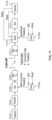
- FIG. 10illustrates a block diagram of circuitry employed to implement analog wireless communication between a transmission detector panel and a portable/handheld scanner, in accordance with an embodiment of the present specification.
- a PMT and pre-amplifier 1002 of a transmission detector panelsuch as shown in FIG. 7 A, 7 B
- an amplitude modulator transmitter 1004which communicates wirelessly with an amplitude de-modulator receiver 1006 provided within, or on a surface of, a portable/handheld scanner 1008 (such as shown in FIG. 8 C ).
- Analog signals communicated by the PMT 1002are demodulated by the receiver 1004 and are input to the scanner 1008 without conversion to digital form.
- the transmitter, receiver 1002 , 1004comprise an ultra-high frequency (UHF) band antennae having a frequency range of 400-480 MHz.
- the transmitter, receiver 1002 , 1004also operate in the FM range of frequencies.
- the embodiment shown in FIG. 10provides low cost and low power consumption solution for no-delay analog wireless communication between a transmission detector panel and a portable/hand-held scanner over a large distance, as described above.
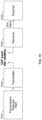
- FIG. 11illustrates a block diagram of circuitry employed to implement digital wireless communication between a transmission detector panel and a portable/handheld scanner, in accordance with an embodiment of the present specification.
- a PMT of a transmission detector panel 1102(such as shown in FIG. 7 A, 7 B ) generates analog detector signals which are amplified by an amplifier 1104 and converted to digital form by an analog to digital (A/D) converter 1106 before being transmitted by a transmitter 1108 .
- A/Danalog to digital
- the transmitted digital signalsare received by a receiver 1110 provided within, or on an external surface of, the scanner, buffered using a buffer circuit 1112 and converted to analog form by a digital to analog (D/A) converter 1113 before being input to the scanner 1114 .
- the receiver 1110 , buffer circuit 1112 and the D/A converter 1113are provided as compact circuitry on an external surface of the scanner 1114 .
- data at the transmitter and the receiver endsis synchronized by using a unifying clock source, either wirelessly from a global positioning satellite (GPS) source or hardwire-based clocks 1116 a , 1116 b.
- GPSglobal positioning satellite
- conversion and time stamp dataare sent over WiFi or Bluetooth connection established between the transmitter 1108 and the receiver 1110 .
- the conversion and time stamp dataare sent over a 2.4 GHz WiFi connection.
- the transmitter 1108comprises built in re-transmit capability.
- the buffer circuit 1112receives time stamps from both the clocks 1116 a , 1116 b as well as the wirelessly transmitted data from the transmitter 1110 , stores the time stamps and the data for a predefined time period and feeds said data to the digital to analog (D/A) converter 1113 at a delay equal to the predefined time period.
- D/Adigital to analog
- data indicative of the state of rotation, a position of rotation, the rate of rotation, and/or a time taken for one rotation of a collimator wheel, as discussed above in relation to FIG. 9is also fed to the buffer circuit 1112 and used to determine the predefined time period used to define or establish the delay.
- the time periodis equal to the time taken for one rotation of the collimator wheel of the scanner 1114 and used to establish the delay imposed by the buffer circuit 1112 before feeding the received wireless transmission data to the analog to digital converter 1113 .
- the digital wireless communication circuit illustrated in FIG. 11is a robust design that can achieve the desired results even in noisy environments.
- FIGS. 12 A and 12 Billustrate a hand-held imaging system 193 which may be used with a thin wireless detector panel such as described in the present specification.
- a traditional detectorwith, for example, a cross-section of 10 cm ⁇ 10 cm (100 cm 2 ), weighs about a half a kilogram.
- the imaging system 193comprises a 10-cm cube of WSF, weighing no more than twice as much, which is made of individual WSF 10 cm ⁇ 10 cm detectors, each less than 5 mm thick, that can be unfolded to present a backscatter detection area of at least 2,000 cm 2 , a twenty-fold increase in this example.
- FIG. 12 A, 12 Bshows an example in which four detectors 191 fold or slide out of hand-held scanner 193 to substantially increase the detection efficiency, especially for items concealed deeper in the object being inspected.
- Backscatter detectors 195straddle irradiating beam 197 .
- FIG. 12 Cillustrates the imaging system 193 connected with a transmission detector panel 194 placed at a distance from the system 193 , wirelessly as explained above, in order to obtain both a backscatter and a transmission image of an object being scanned. Referring to FIGS.
- an operator 1202in order to operate the imaging system 193 in conjunction with the transmission detector panel 194 , an operator 1202 is required to position the detector 194 with respect to the target being scanned 1204 , energize the hand-held imaging system 193 , translate the imaging system 193 across the region of the target 1204 and collect the scattered and transmission data for review.
- backscattered photonsare detected by the built-in backscatter detector of the hand-held imaging system 193 .
- a transmission image as well as a backscatter image of an object 1204 being scannedmay be obtained simultaneously, thus providing an operator with additional information regarding the object being scanned and enhancing the scan quality.
- the inspection of the underside of vehicles by a portable X-ray backscattering systempresents special problems.
- the road clearance of carsis not more than 8′′ and can be as little as 6′′.
- Fixed inspection systemssuch as portals, can place a detector in the ground or above.
- Mobile under-vehicle inspection systemshowever, which are needed for security in many areas, have never been developed.
- Inspectorsrely on passive inspection tools such as mirrors and cameras, which miss contraband in the gas tank or are camouflaged to appear innocuous.
- FIGS. 13 A and 13 Billustrate a portable X-ray backscatter system that is not more than 6′′ high, and which can be connected to a transmission detector panel positioned at a location above the vehicle 229 being scanned, wirelessly as explained above.
- the backscatter system 231comprises an electromagnetic scanner 221 of an electron beam across an anode. Electromagnetic scanner 221 is driven by electronics module 223 .
- the X-raysare collimated by a linear array of apertures 251 that span, for example, 30′′ of the underside in one pass.
- the Sc-WSF detectors 227are mounted on each side of the X-ray tube so as detect X-rays 236 backscattered from vehicle 229 . Power supplies, pulse and image processors can be mounted appropriately.
- a chassis of inspection unit 231 on wheels 232may be adapted to be maneuvered under vehicle 229 by motor or manual control.
- the vehicle 229is scanned using only the backscatter system 231 , some of the threat items concealed in the underside of the vehicle are not visible in the obtained scanned image.
- the backscatter scanning system 231is connected wirelessly to a transmission detector panel positioned at a location above the vehicle 229 being scanned, even an explosive object such as a pipe bomb concealed in the underside of the vehicle 229 is visible in the transmission scan image.
- FIG. 13 Cillustrates an image 1304 of the underside of a vehicle obtained by using a portable backscatter scanning system, in accordance with an embodiment of the present specification. As shown in FIG.
- FIG. 13 Cillustrates an image 1306 of the underside of a vehicle obtained by using a portable backscatter scanning system wirelessly connected to a transmission detector panel, in accordance with an embodiment of the present specification.
- the pipe bomb 1308is clearly visible in the scanning image 1306 obtained by operating a WSS detector panel in a transmission mode connected wirelessly to the underside of a vehicle obtained by using the portable backscatter scanning system 231 , which scans the underside of the vehicle 229 .
Landscapes
- Physics & Mathematics (AREA)
- High Energy & Nuclear Physics (AREA)
- Life Sciences & Earth Sciences (AREA)
- General Physics & Mathematics (AREA)
- Spectroscopy & Molecular Physics (AREA)
- Health & Medical Sciences (AREA)
- Molecular Biology (AREA)
- General Life Sciences & Earth Sciences (AREA)
- Geophysics (AREA)
- Engineering & Computer Science (AREA)
- General Engineering & Computer Science (AREA)
- Analysing Materials By The Use Of Radiation (AREA)
Abstract
Description
The present application is a continuation application of U.S. patent application Ser. No. 17/102,299 (the '299 application), entitled “Wireless Transmission Detector Panel for an X-Ray Scanner” and filed on Nov. 23, 2020, which is herein incorporated by reference in its entirety.
The '299 application relates to U.S. patent application Ser. No. 17/061,340, entitled “Wavelength-Shifting Sheet Scintillation Detectors”, filed on Oct. 1, 2020, which is a continuation of U.S. patent application Ser. No. 16/382,973, entitled “Wavelength-Shifting Sheet Scintillation Detectors”, filed on Apr. 12, 2019, now issued U.S. Pat. No. 10,830,911, issued on Nov. 10, 2020, which, in turn, relies on U.S. Patent Provisional Application No. 62/687,550, entitled “Wavelength-Shifting Sheet Scintillation Detectors”, filed on Jun. 20, 2018, for priority, all of which are herein incorporated by reference in their entirety.
In addition, the '299 application relates to U.S. patent application Ser. No. 16/855,683, entitled “Spectral Discrimination Using Wavelength-Shifting Fiber-Coupled Scintillation Detectors”, filed on Apr. 22, 2020, which is a continuation of U.S. patent application Ser. No. 16/382,951, filed on Apr. 12, 2019, now issued as U.S. Pat. No. 10,670,740, issued on Jun. 2, 2020, which is a continuation-in-part of U.S. patent application Ser. No. 16/242,163 entitled “Spectral Discrimination using Wavelength-Shifting Fiber-Coupled Scintillation Detectors” and filed on Jan. 8, 2019, all of which are herein incorporated by reference in their entirety.
In addition, the '299 application relates to U.S. patent application Ser. No. 16/242,163, entitled “Spectral Discrimination using Wavelength-Shifting Fiber-Coupled Scintillation Detectors” and filed on Jan. 8, 2019, which is a continuation of U.S. patent application Ser. No. 15/490,787, of the same title, filed on Apr. 18, 2017, now issued as U.S. Pat. No. 10,209,372, issued on Feb. 19, 2019, which is a continuation of U.S. patent application Ser. No. 15/050,894, of the same title, filed on Feb. 23, 2016, and issued as U.S. Pat. No. 9,658,343 on May 23, 2017, which, in turn, is a division of U.S. patent application Ser. No. 13/758,189, of the same title, filed on Feb. 4, 2013, and issued as U.S. Pat. No. 9,285,488 on Mar. 15, 2016. U.S. patent application Ser. No. 13/758,189 claims priority from the following applications:
U.S. Patent Provisional Application No. 61/607,066, entitled “X-Ray Inspection using Wavelength-Shifting Fiber-Coupled Detectors”, filed on Mar. 6, 2012;
U.S. Patent Provisional Application No. 61/598,521, entitled “Distributed X-Ray Scintillation Detector with Wavelength-Shifted Fiber Readout”, and filed on Feb. 14, 2012; and
U.S. Patent Provisional Application No. 61/598,576, entitled “X-Ray Inspection Using Wavelength-Shifting Fiber-Coupled Detectors”, and filed on Feb. 14, 2012.
The above-mentioned applications are incorporated herein by reference in their entirety.
The present specification relates to systems and methods of wirelessly coupling detectors to X-ray scanners and, in particular, wirelessly coupling a transmission detector panel to a backscatter system.
Materials, such as narcotics, explosives or currency, and objects, such as weapons or people, are concealed within or behind barriers with the intention that the materials or objects remain undetected by routine or targeted security checks. Scanning devices are well known which use a variety of sensing methods to detect concealed materials and objects. These scanning devices include transmission X-ray imaging systems, Compton scatter-based backscatter imaging systems, chemical sniffing trace detection equipment, thermal imaging camera systems and so on. Such scanning devices may be used alone or in combination to provide a comprehensive level of security. However, such devices tend either to be large and expensive (e.g. transmission X-ray imaging systems) or insensitive to carefully hidden materials (e.g. trace detection equipment and camera systems) which means that their utility is restricted to certain high throughput situations such as sea ports and land borders, airport checkpoints and other areas of the type.
Scatter imaging, in which the X-rays scattered (typically in a general backward direction) by a material, offers several unique inspection capabilities and operational features. Scatter imaging allows images to be obtained even when the imaged object is accessible from only one side. Moreover, since the scatter signal falls off rapidly with increasing depth into the object, backscatter images effectively represent a “slice” of the object characteristic of the side nearest to the X-ray source, thereby reducing problems of image clutter that typically confound transmission images. The Compton effect, which dominates X-ray scatter in certain energy ranges, dominates the interaction of x-rays with dense low-atomic-number (low-Z) materials. Narcotic drugs tend to produce bright signatures in a backscatter image, as do organic explosives, making backscatter imaging a useful imaging modality for bomb or drug detection. Further, in scatter detection, alignment requirements of the x-ray beam with detectors or collimation devices are less exacting, as compared to transmission imaging, thereby enabling rapid deployment in a wide range of inspection scenarios.
With flying-spot technology, it is possible to acquire images using detectors specifically positioned to collect the scattered X-rays. In a typical flying-spot system, a thin “pencil beam” of X-rays is rapidly and repetitively swept through a source-centered, vertically-oriented “fan” of beam paths that are arranged to intercept the object under inspection. At the same time, the object is moved at a constant, yet slower speed along a path perpendicular to the fan, on a horizontally moving conveyor belt, for example. The pencil beam traverses the object in point-by-point raster fashion, and the entire object is scanned as it passes through the fan plane over a period ranging from a few seconds to a few minutes depending upon the length of the object.
Although the total scan time may be seconds to minutes in duration, the actual exposure time of any part of the scanned object is only the brief time it takes for the pencil beam to sweep across a given pixel. That exposure time is typically in the range of microseconds, depending on the design and the application, and yields an entrance exposure to the scanned object that constitutes a low dose to the object. This also means that there is little radiation available to scatter into the environment, therefore the doses to operators and other bystanders is correspondingly low.
U.S. Pat. No. 10,168,445, assigned to Applicant of the present specification, discloses a compact, light-weight, portable and hand-held system or device that can be maneuvered to reach relatively inaccessible locations and scan behind concealing barriers that are otherwise opaque against chemical and optical probes. The disclosed system is a compact, hand-held device that uses the principle of X-ray backscatter to provide immediate feedback to an operator about the presence of scattering and absorbing materials, items or objects behind concealing barriers irradiated by ionizing radiation, such as X-rays. Feedback is provided in the form of a changing audible tone whereby the pitch or frequency of the tone varies depending on the type of scattering material, item or object. The operator obtains a visual scan image on a screen by scanning the beam around a suspect area or anomaly.
Scanning pencil beams of X-rays in such devices not only reveal interior objects by analyzing the backscattered radiation but, in some applications, can obtain additional information by the simultaneous analysis of transmission (TX) and backscattered (BX) radiation. In this configuration, the handheld device comprises one or more BX detectors while a TX detector is placed at a distance from the scanner and is in wired communication with the handheld device. The transmission detector is coupled with the scanner by using power and signal cables in order to synchronize the BX detector of the scanner and the transmission detector. In practice, however, it is very cumbersome to properly position the transmission detector relative to the backscatter system since the distance between the scanner and the transmission detector panel may be large and cables extending through this distance may be cumbersome, difficult to manage and cause delays or inefficiencies in the scanning process. Unfortunately, there are no practical alternative approaches to wired transmission detectors because of the need for a high degree of signal synchronization and the inherent latency that exists in known wireless approaches.
Hence, there is a need for systems and methods for wirelessly coupling an X-ray scanner comprising a backscatter detector with a transmission detector placed at a distance from the scanner. There is a need for systems and methods for ensuring a high degree of synchronization with wireless signals in an X-ray scanner comprising a backscatter detector with a wireless transmission detector placed at a distance from the scanner.
The following embodiments and aspects thereof are described and illustrated in conjunction with systems, tools and methods, which are meant to be exemplary and illustrative, and not limiting in scope. The present application discloses numerous embodiments.
In some embodiments, the present specification discloses an X-ray scanner, comprising: a housing; an X-ray source positioned in the housing; a backscatter detector physically coupled to the housing system; a transmission detector adapted to be positioned remote from the housing and not physically coupled to the housing, wherein the transmission detector is adapted to generate a signal when X-rays emitted by the X-ray source impinge on a surface of the transmitter detector after passing through an object being scanned and wherein the transmission detector further comprises a wireless transmitter for transmitting the signal; and a controller physically coupled to the housing and adapted to control an operation of the X-ray source, wherein the controller comprises a receiver configured to receive the wirelessly transmitted signal from the transmission detector, wherein the transmitter and the receiver operate in a frequency range of 6 Mhz to 6 Ghz.
Optionally, the transmitter is positioned on an external surface of the transmission detector.
Optionally, the transmission detector further comprises a pre-amplifier coupled with the at least one photomultiplier tube and is adapted to amplify the signal.
Optionally, the X-ray scanner is configured to be hand-held.
Optionally, the transmitter further comprises an amplitude modulator adapted to modulate an amplitude of the signal before transmitting the signal. Optionally, the controller comprises a buffer and wherein the receiver comprises an amplitude demodulator for demodulating the amplitude of the transmitted signal before transmitting the signal to the buffer.
Optionally, the transmitter polarizes the signal before transmission for avoiding interference with one or more signals having a same frequency as the signal being transmitted, wherein the polarization is one of: a horizontal polarization or a vertical polarization.
Optionally, the receiver is positioned on an external surface of the transmission detector.
In some embodiments, the present specification discloses an X-ray scanner comprising: a housing; an X-ray source positioned in the housing; a rotating collimator positioned proximate the X-ray source and configured to collimate X-ray beams emanating from the X-ray source; a backscatter detector physically coupled to the housing system; a transmission detector adapted to be positioned remote from the housing and not physically coupled to the housing, wherein the transmission detector is adapted to generate a signal when the X-ray beams emitted by the X-ray source impinge on a surface of the transmitter detector after passing through an object being scanned and wherein the transmission detector further comprises a wireless transmitter for transmitting the signal; and a controller physically coupled to the housing and adapted to control an operation of the X-ray source, wherein the controller comprises a receiver configured to receive the wirelessly transmitted signal from the transmission detector and wherein the controller further comprises a buffer coupled to the receiver and configured to store data indicative of the signal for a predefined period of time, wherein the predefined period of time is a function of at least one of a time when the signal is generated, a position of the rotating collimator, a time when the signal is received, or a time when a signal from the backscatter detector is generated.
Optionally, the transmission detector comprises a plurality of wavelength shifting fibers (WSF) coupled with at least one photomultiplier tube.
Optionally, the X-ray scanner further comprises an analog to digital (A/D) converter coupled to the transmission detector and adapted to convert the signal to a digital signal, wherein an operation of the A/D converter is synchronized using time data from a first clock coupled with the transmission detector.
Optionally, the transmitter coupled with the transmission detector is adapted to transmit the signal and time data from the first clock.
Optionally, the receiver coupled with the controller is adapted to receive the signal and time data from the first clock.
Optionally, the predefined period of time is a function of the time data and the position of the rotating collimator.
Optionally, the controller comprises a digital to analog (D/A) converter coupled with the buffer and adapted to convert the buffered signal to an analog signal after the expiry of the predefined period of time, wherein an operation of the D/A converter is synchronized using time data from a second clock coupled with the buffer, and wherein the time data of the second clock is synchronized using time data of the first clock.
Optionally, the transmitter is positioned on an external surface of the transmission detector.
Optionally, the transmission detector further comprises a pre-amplifier coupled with at least one photomultiplier tube and is adapted to amplify the signal.
Optionally, the X-ray scanner is configured to be hand-held.
Optionally, the transmitter further comprises an amplitude modulator adapted to modulate an amplitude of the signal before transmitting the signal.
Optionally, time data the first clock and time data of the second clock are synchronized using at least one of GPS based clock system or a temporary hardwire connection.
Optionally, the predefined period of time is a function of a time taken for one rotation of the collimator.
Optionally, the controller comprises a digital to analog (D/A) converter coupled with the buffer and adapted to convert the buffered signal to an analog signal at a delay equal to a time taken for one rotation of the collimator wheel of the scanner.
Optionally, the transmitter is configured to polarize the signal before wirelessly transmitting the signal to avoid interfering with one or more signals having a same frequency as the signal being transmitted
Optionally, the polarization is at least one of a horizontal polarization such that an electrical field of the signal oscillates in a horizontal plane, a vertical polarization such that the electrical field of the signal oscillates in a vertical plane, or an angled plane such that the electrical field of the signal oscillates in a plane that has a non-zero angle relative to the horizontal plane and the vertical plane.
The aforementioned and other embodiments of the present shall be described in greater depth in the drawings and detailed description provided below.
These and other features and advantages of the present invention will be further appreciated, as they become better understood by reference to the detailed description when considered in connection with the accompanying drawings:
In various embodiments, the present specification provides a transmission detector panel that may be coupled wirelessly to a portable/handheld scanner. While aspects of the present specification may be described herein with reference to particular types of handheld scanners and transmission detectors, the system and method described in detail herein may be used to couple various types of scanners wirelessly with various types of transmission detectors.
In accordance with embodiments of the present specification, the optical coupling of scintillator material to optical waveguides, and, more particularly, to wavelength-shifting fibers, advantageously enables objectives including those peculiar to the demands of X-ray scatter detection.
The term “image” shall refer to any unidimensional or multidimensional representation, whether in tangible or otherwise perceptible form, or otherwise, whereby a value of some characteristic (such as fractional transmitted intensity through a column of an inspected object traversed by an incident beam, in the case of X-ray transmission imaging) is associated with each of a plurality of locations (or, vectors in a Euclidean space, typically R2) corresponding to dimensional coordinates of an object in physical space, though not necessarily mapped one-to-one thereto. An image may comprise an array of numbers in a computer memory or holographic medium. Similarly, “imaging” refers to the rendering of a stated physical characteristic in terms of one or more images.
For purposes of the present description, and in any appended claims, the term “thickness,” as applied to a scintillation detector, shall represent the mean extent of the detector in a dimension along, or parallel to, a centroid of the field of view of the detector. The term area, as applied to a detector, or, equivalently, the term “active area” shall refer to the size of the detector measured in a plane transverse to centroid of all propagation vectors of radiation within the field of view of the detector.
Terms of spatial relation, such as “above,” “below,” “upper,” “lower,” and the like, may be used herein for ease of description to describe the relationship of one element to another as shown in the figures. It will be understood that such terms of spatial relation are intended to encompass different orientations of the apparatus in use or operation in addition to the orientation described and/or depicted in the figures.
As used herein, and in any appended claims, the term “large-area detector” shall refer to any single detector, or to any detector module, subtending an opening angle of at least 30° in each of two orthogonal transverse directions as viewed from a point on an object undergoing inspection, equivalently, characterized by a spatial angle of at least π steradians.
A “conveyance” shall be any device characterized by a platform borne on ground-contacting members such as wheels, tracks, treads, skids, etc., used for transporting equipment from one location to another.
Where an element is described as being “on,” “connected to,” or “coupled to” another element, it may be directly on, connected or coupled to the other element, or, alternatively, one or more intervening elements may be present, unless otherwise specified.
In various embodiments, a “computing device” includes an input/output controller, at least one communication interface and a system memory and is used to operate the handheld scanner of the present specification. The system memory includes at least one random access memory (RAM) and at least one read-only memory (ROM). These elements are in communication with a central processing unit (CPU) to enable operation of the computing device. In various embodiments, the computing device may be a conventional standalone computer or alternatively, may be contained within the system as described in the present specification. In some embodiments, execution of a plurality of sequences of programmatic instructions or code, which are stored in one or more non-volatile memories, enable or cause the CPU of the computing device to perform various functions and processes such as, for example, performing image reconstruction for display on a screen. In alternate embodiments, hard-wired circuitry may be used in place of, or in combination with, software instructions for implementation of the processes of systems and methods described in this application. Thus, the systems and methods described are not limited to any specific combination of hardware and software.
In embodiments, a controller is included in the handheld scanner housing and is used to control the operation of the X-ray source and the routing, transmission, processing, and/or storage of the detection signals. In embodiments, the controller is physically coupled to the housing of the handheld scanner and is adapted to control an operation of the X-ray source. In embodiments, the controller comprises a receiver configured to receive the wirelessly transmitted signal from a transmission detector, wherein the transmitter and the receiver operate in a frequency range of 400-480 MHz. In embodiments, the controller is physically coupled to the housing and adapted to control an operation of the X-ray source, whereby the controller comprises a receiver configured to receive the wirelessly transmitted signal from the transmission detector and whereby the controller further comprises a buffer coupled to the receiver and configured to store data indicative of the signal for a predefined period of time. In embodiments, the predefined period of time is a function of at least one of a time when the signal is generated, a position of the rotating collimator, a time when the signal is received, or a time when a signal from the backscatter detector is generated.
The terminology used herein is for the purpose of describing particular embodiments and is not intended to be limiting. The singular forms “a,” “an,” and “the,” are intended to include the plural forms as well.
The present specification is directed towards multiple embodiments. The following disclosure is provided in order to enable a person having ordinary skill in the art to practice the invention. Language used in this specification should not be interpreted as a general disavowal of any one specific embodiment or used to limit the claims beyond the meaning of the terms used therein. The general principles defined herein may be applied to other embodiments and applications without departing from the spirit and scope of the invention. Also, the terminology and phraseology used is for the purpose of describing exemplary embodiments and should not be considered limiting. Thus, the present invention is to be accorded the widest scope encompassing numerous alternatives, modifications and equivalents consistent with the principles and features disclosed. For purpose of clarity, details relating to technical material that is known in the technical fields related to the invention have not been described in detail so as not to unnecessarily obscure the present invention.
In the description and claims of the application, each of the words “comprise” “include” and “have”, and forms thereof, are not necessarily limited to members in a list with which the words may be associated. It should be noted herein that any feature or component described in association with a specific embodiment may be used and implemented with any other embodiment unless clearly indicated otherwise.
The principles described above are applicable throughout each of the embodiments described in the present specification and will not be repeated with respect to each embodiment.
Handheld Portable X-Ray Scanner with Backscatter Detectors
At least onehandle 112 is provided on, for example, theupper surface 110 to allow the operator to hold thehousing 105 conveniently in one or both hands and manipulate thedevice 100 to point thefront surface 114 towards and at different regions on the object under inspection. In alternate embodiments one or more handles are provided on one or more areas or regions such as theupper surface 110, the base, thefirst side 118 and/or the second side so that single-handed or two-handed operation ofdevice 100 is facilitated, depending on what is easiest for the operator.
Referring back toFIGS.1 and2 , thehousing 105 comprises anX-ray tube 140 wherein acorresponding anode 141, also referred to as a target, emits a spatially localizedX-ray beam 145 through anopening 142, also referred to as an aperture. At least oneshield 143, formed of an X-ray absorptive material, such as tungsten or uranium, surrounds and enclosesanode 141 to absorb stray radiation emitted fromanode 141.Opening 142, defined throughshield 143, is provided with a size and thickness which enables opening142 to act as a collimator in forming or shaping and limiting the X-ray radiation, emitted fromanode 141, into a shaped beam ofX-rays 145. In one embodiment,X-ray beam 145 is shaped into a pencil beam.
A cathode and heater filament assembly (enclosed within housing105) is held at a substantial potential difference (using a chargeable battery also enclosed within the housing105) with reference toanode 141 by a kilovolt power supply (wrapped around at least one tube shielding143, in one embodiment). This potential difference causes thermionic electrons freed by the heated cathode (heated using the heater filament) to be directed and drawn toanode 141 at sufficiently high velocity to result in the generation ofX-ray beam 145 AnX-ray beam 145 emerges through anopening 144 at the center offront surface 114 ofhousing 105, in a direction substantially perpendicular tofront surface 114. At least oneX-ray backscatter detector 150, is positioned adjacent to and behindfront surface 114 in order to maximize detected backscatter signal.
Scatter imaging in which the X-rays are scattered by a material (typically in a generally backward direction) offers several unique inspection capabilities and operational features. Scatter imaging allows images to be obtained even when the imaged object is accessible from only one side. Moreover, since the scatter signal falls off quite rapidly with increasing depth into the object, backscatter images effectively represent a “slice” of the object characteristic of the side nearest to the X-ray source, thereby reducing problems of image clutter that may confound transmission images. The Compton effect, which dominates X-ray scatter in the energy range typically employed in accordance with the present invention, dominates the interaction of X-rays with dense low-atomic-number (low-Z) materials. Narcotic drugs tend to produce the bright signatures in a backscatter image, as do organic explosives, making backscatter imaging a useful imaging modality for bomb or drug detection. Finally, alignment requirements of the x-ray beam with detectors or collimation devices are less exacting than for transmission imaging thereby enabling rapid deployment in a wide range of inspection scenarios.
Flying-spot technology makes possible the acquisition of images using detectors specifically positioned to collect the scattered X-rays. In a typical flying-spot system, a thin “pencil beam” of X-rays is rapidly and repetitively swept through a source-centered, vertically-oriented “fan” of beam paths that are arranged to intercept the object under inspection. At the same time, the object is moved at a constant, slower speed along a path perpendicular to the fan, on a horizontally moving conveyor belt for example. The pencil beam is made to traverse the object in point-by-point raster fashion, and the entire object is scanned as it passes through the fan plane over a period ranging from a few seconds to a few minutes depending upon the length of the object.
Although the total scan time may be seconds to minutes in duration, the actual exposure time of any part of the scanned object is only the brief time it takes for the pencil beam to sweep across a given pixel. That exposure time is typically in the range of microseconds, depending on the design and the application, and yields an entrance exposure to the scanned object that constitutes a low dose to the object also means that there is little radiation available to scatter into the environment, so the doses to operators and other bystanders is correspondingly low.
Various means are known in the art for mechanically or electronically sweeping a beam of penetrating radiation, including, for example, therotating chopper wheel 34 depicted inFIG.3 or electronic scanning is described in detail, for example, in U.S. Pat. No. 6,421,420, issued Jul. 16, 2002, which is incorporated herein by reference. In embodiments employing a mechanicalrotating chopper wheel 34, as the chopper wheel rotates in a clockwise direction, penetrating radiation emitted from the target ofX-ray tube 32 passes successively through a plurality (typically, three or four) of channels.Wheel 34 is fabricated from a material, typically lead, that blocks transmission of X-rays except throughapertures 36. X-rays emerge from the currently illuminated channel as a pencil beam that is swept across an object undergoing inspection as thewheel 34 rotates. The dimensions of the X-ray beam typically govern the resolution of a system such as the one depicted.Aperture 36 may have various shapes, and may be circular or rectangular, and may be more specifically tailored. Other X-ray generation approaches may be used to produce a similar sweeping pencil beam, such as spinning discs with elongated slits, wheels with hollow spokes, are alternate embodiments.
In embodiments,detector modules 182 comprise transmission detectors placed behind an object being irradiated with the X-ray beam (such that the object is between the X-ray source and the detector), for receiving a transmission beam comprising X-rays that are transmitted through the object. In an embodiment, the received beam is absorbed by a scintillator layer of the detector and subsequently transmitted to a photomultiplier tube for detection, which in turn transmits the detected data to a data acquisition system for processing.
In embodiments, separate, large-area detectors are deployed adjacent to the beam plane on the X-ray source side of the scanned object, and with their active surfaces oriented toward the scanned object. These detectors need only provide a large solid angle for collection of scattered radiation; no critical alignments are required. In this location these detectors respond to x-rays which are scattered generally back toward the source from the object.
In an embodiment, particularly useful for lower energy (140 keV 160 keV) X-ray systems, the output frombackscatter detectors 182 are switched to a pulse counting circuit during a fraction of the operating cycle in which the source of X-ray irradiation is switched off. During this period, individual neutrons or gamma rays can be detected and analyzed. The efficiency of the backscatter detectors of an X-ray inspection system for detecting neutrons or gamma ray has been discussed above.
It should be noted that the maximum energy of the X-rays produced byX-ray tube 32 determines the ability of these X-rays to penetrate into the object under inspection i.e., the higher the maximum X-ray energy, the more penetration can be achieved. Similarly, the higher the energy of the scattered X-ray photon, the more likely it is to escape through the object under inspection back to anX-ray detector 182. Therefore, in accordance with an aspect it is desirable to have high X-ray energy to maximize depth of inspection within the object.
In an embodiment, a plurality of collimator vanes, blades, fins orplates 255 are optionally positioned in front ofdetectors 250 and behindfront surface 214.Housing 205 comprises an X-ray tube whose anode, also referred to as a target, emits a spatially localizedX-ray beam 245
Detector Panels
In various embodiments, and as described above, a portable/handheld scanner such as that shown inFIGS.1,2,3,4 and8E comprises an internal backscatter detector (not visible in the figure). In embodiments of the present specification, transmission detector panels are used in conjunction with portable hand held scanners to obtain images of objects being scanned. The detector panel is designed for placement at any position relative to a portable/handheld scanner. In an embodiment, when the detector panel is placed in the path of a beam of radiation generated by an X-ray source, the detector panel acts as a transmission detector.
With the use of detector panels along with portable/hand held scanners, a challenge is that there is typically no pre-established physical configuration between the detector and the scanning source. If the position of the source relative to the detector is known/fixed, the location of impurities and irregularities in the detector may be fixed, and hence, any detected data could be automatically corrected for said irregularities. Specifically, the gain could be corrected (increased/decreased) to account for spots or lines due to issues in manufacturing of the scanner/detector. However, with the use of the detector panel as described in the present specification, the relative configuration of the detector panel and the scanning source is changeable, making it difficult to predict precisely the location of non-uniformities in the scanning image. Hence, the non-uniformities that are inherent to the detector response cannot be corrected using known gain correction methods. Without gain calibration, the signals received by using the detector as shown inFIG.5 will be raw and may include defects such as, but not limited to: gain non-uniformity due to variations in the X-ray absorption in scintillator; non-uniformity in the scintillator light production and propagation; and non-uniformity in light collection across the area of detector.
The challenge, therefore, is to create a detector panel which generates the same light output as a photo multiplier tube (PMT). The more uniform the response, the lower the variability. With the use of conventional fixed X-ray source detector configurations, a variability ranging from 30% to 40% may be tolerated. However, for handheld scanner and detector configurations, a variability of 10% or less is required.
In an embodiment an X-ray detector comprising a screen fabricated from a scintillator material, such as phosphor, that is optically coupled, in optical contact or in physical communication with a wavelength-shifting sheet (WSS), which shifts light absorbed from the scintillator screen may be used as a transmission detector panel wirelessly connected to a handheld portable backscatter X-ray imaging system. The wavelength shifting sheet is coupled to a wavelength shifting fiber or sheet at the edge of the wavelength shifting sheet that is configured to collect a plurality of first shifted rays. The rays collected from the edge are transmitted through to a photodetector, such as a photo multiplier tube (PMT).
The use of a Wave Shifting Sheet (WSS) as the primary material for flying spot transmission X-ray detection reduces or eliminates objectionable, highly visible defects which are inherent in X-ray detectors implemented with solely Wave Shifting Fibers (WSF). In addition, the WSS detector can be fabricated using low cost plastic materials assembled in a simple manufacturing process.
Since, backscatter systems have imaging limitations in certain applications where transmission imaging is advantageous, the WSS detector is implemented as a transmission scan panel that can be used with any commercially available handheld scanning system such as, but not limited to, the MINI Z™ scanning system, and/or embodiments disclosed in U.S. Pat. No. 10,168,445, which is incorporated herein by reference, to provide a simultaneous secondary image. As described above, the detector provides a transmission image when placed directly behind an item being scanned, or an additional backscatter image when placed on the near side of the object being scanned. The secondary image is displayed next to the standard Backscatter image on a display screen coupled with the MINI Z scanning system. In various embodiments, the transmission scan panel is portable, light-weight, and connects to handheld scanning system with a simple, single cable connection.
In embodiments of the present specification, to address any non-uniformity issues, a detector panel comprising wavelength shifting fibers (WSF) is employed. The use of enhanced resolution WSF detectors increases spatial sensitivity of the portable X-ray imaging system through the use of multiplexed WSF coupled to a multi-anode photo multiplier tube (PMT). Typically, the detector comprises multiple layers of WSF in order to determine both the high resolution content of the image by detecting the intensity captured by individual fibers, as well as low resolution mapping in order to determine a coarse location of the focal spot. In this way, a high resolution image is generated with a minimum of data individual channels, thus saving cost and complexity of the system.
Advantages of using the WSF detector panels include increases in the efficiency of detection and the low geometrical profile of implementation. This allows greater freedom in designing a detection system and it makes entirely new, space constrained applications possible. The mechanical flexibility of the detector structure allows shaping the detector surface to conform to the application, such as an implementation in which an imaged object is surrounded by detector volume. The low profile also makes it relatively easy to orient and shield the detector area in ways to minimize the detection of unwanted scatter radiation (crosstalk) from a nearby X-ray imaging system.
Wireless Transmission Detector Panels
In various embodiments, by using a transmission detector panel such as is shown inFIG.5 , along with a backscatter detector built within a portable/hand held scanner, a transmission image as well as a backscatter image of an object being scanned may be obtained simultaneously thus providing an operator with additional information regarding the object being scanned and enhancing the scan quality.
In embodiments, a controller is included in the handheld scanner housing and is used to control the operation of the X-ray source and the routing, transmission, processing, and/or storage of the detection signals. In embodiments, the controller is physically coupled to the housing of the handheld scanner and is adapted to control an operation of the X-ray source. In embodiments, the controller comprises a receiver configured to receive the wirelessly transmitted signal from a transmission detector. In embodiments, the wireless transmission panel, and thus, the transmitter and the receiver are configured to operate using a range of radio spectrum reserved internationally for industrial, scientific and medical (ISM) purposes. These frequencies can range from 6 Mhz to 6 Ghz and are allocated in specific bands for non-regulated devices. Specifically, the panel could utilize the 2.4 and 5.7 GHz ISM bands which are commonly used for Bluetooth and wireless modems. While there are regional requirements for some bands, embodiments of the present specification are compatible with the full range. In an embodiment, the transmitter and the receiver operate within a frequency range of 400-480 MHz.
In embodiments, the transmitted signal from the transmission detector may be horizontally or vertically polarized, or polarized to a certain angle relative to a horizontal or vertical plane, before transmission. As is known, the polarization of the transmitted signal is achieved by the polarization of the signal's electric field, wherein for a horizontally polarized transmission signal, the electric field moves sideways in a horizontal plane; and for a vertically polarized transmission signal, the electric field oscillates up and down in a vertical plane. In embodiments, the transmitted signal is either vertically or horizontally polarized, depending upon a desired region of transmission, in order to avoid having the transmitted signal interfere with other signals in the region having frequencies which are the same as the transmitted signal. In embodiments, a controller may be configured to allow an operator of the system, or the system itself based on data indicative of a presence of other signals, to select an angle or degree of polarization, including at least one of a horizontal polarization (where the electrical field oscillates in a horizontal plane), a vertical polarization (where the electrical field oscillates in a vertical plane), an angled polarization (where the electrical field oscillates in a plane that is angled relative to a horizontal or vertical plane). Upon selecting a degree and/or angle of oscillation, the controller may cause the transmitter to generate a field having oscillation characteristics in accordance with the selected degree and/or angle of oscillation, as described above.
In embodiments, the controller is physically coupled to the housing and adapted to control an operation of the X-ray source, whereby the controller comprises a receiver configured to receive the wirelessly transmitted signal from the transmission detector and whereby the controller further comprises a buffer coupled to the receiver and configured to store data indicative of the signal for a predefined period of time. In embodiments, the predefined period of time is a function of at least one of a time when the signal is generated, a position of the rotating collimator, a time when the signal is received, or a time when a signal from the backscatter detector is generated.
In various embodiments, and as described above, a portable/handheld scanner such as that shown inFIG.8E comprises an internal backscatter detector (not visible in the figure). Usually, thetransmission detector panel 855 is coupled with the portable/handheld scanner 850 by using power and signal cables in order to synchronize the backscatter detector of thescanner 850 and thetransmission detector 855. Since, the distance between the portable/handheld scanner 850 and thedetector panel 855 may be up to 50 feet, cables extending through this distance may be cumbersome and cause disruption in the scanning process. Hence, in an embodiment, the present specification provides a transmission detector panel that may be coupled wirelessly to a portable/handheld scanner. In various embodiments, the wireless transmission detector panel of the present specification may communicate with a portable/handheld scanner over a distance ranging from a few inches to 200 feet even when line of sight is not available between the detector panel and the scanner.
The portable/handheld scanner 850 comprises an X-ray source and a collimator wheel comprising at least four spokes for producing a well-collimated pencil-beam of X rays which is raster scanned across an object being inspected, and the X rays backscattered from the object toward the source are collected by backscattered detectors integrated within the portable/handheld scanner.FIG.9 illustrates a collimator wheel of a portable/handheld scanner, in accordance with an embodiment of the present specification.Collimator wheel 900 comprises fourspokes wheel 900 rotates, each spoke passes before an X-ray source of the portable/handheld scanner to generate one raster scan line corresponding to an object being inspected. Grooves, protrusions, extensions, or members, all collectively referred to as notches,910 mark the commencement of a new raster scan line. Anotch 912 is shown before thefirst spoke 902 and signals the start/reset of the raster scan lines. In embodiments the notches are provided with optical indicators so that a light shining through the wheel indicates a spoke passing before the X-ray source. Anotch 913 may be provided at the center of thewheel 900 for functioning as a wheel rotation indicator. In an embodiment, the timing and spoke timing configuration of a collimator wheel of a portable/handheld scanner are such that a) each raster scan line comprises 900 pixels per line, b) there are 4 acquisitions per displayed pixel, c) there are approximately 5 micro seconds per acquisition, d) there are approximately 20 micro seconds per pixel, e) there are 2640 rotations per min, and e) there are 22.7 milliseconds per wheel revolution, or 176 lines per second are acquired. In some embodiments, the number of acquisitions per displayed pixel is more or less than 4, however the 4 pixel average is used to obtain a desired compromise between resolution and SNR of the scanner.
In various embodiments, wireless communication electronics are provided within a housing of, or on an external surface of the portable/handheld scanner, as well as in data communication with the transmission detector panel. In an embodiment, wireless communication is implemented between a portable/handheld scanner and a transmission detector by using an analog method of synchronizing the integrated backscatter detector of the portable/handheld scanner and the transmission detector panel. In an embodiment, an amount of delay between generation of an X-ray beam and the detection of the beam by a detector is known and may be fixed and calibrated. This known fixed delay may be used to synchronize the backscatter detector and the transmission detector detection timings.
More specifically, in an embodiment, the scanner is provided with an internal data converter that is used to convert detector signals at predefined time intervals, for example, every 5 microseconds and collect the signals over said time interval. When the scanner is connected to a transmission detector panel a similar data conversion and transmission occurs. With fixed, predefined data conversion intervals (e.g. every 5 microseconds), known, fixed delays may be defined and used to synchronize the backscatter and transmission detection signal timings. In an embodiment, each pixel is equivalent to approximately 20 microseconds of data acquisitions.
In an embodiment, analog detection signals generated by a photomultiplier tube (PMT) of the transmission detector panel are communicated (without conversion to digital form) to the portable/handheld scanner.FIG.10 illustrates a block diagram of circuitry employed to implement analog wireless communication between a transmission detector panel and a portable/handheld scanner, in accordance with an embodiment of the present specification. As shown in theFIG.10 , a PMT andpre-amplifier 1002 of a transmission detector panel such as shown inFIG.7A,7B , is coupled with anamplitude modulator transmitter 1004 which communicates wirelessly with anamplitude de-modulator receiver 1006 provided within, or on a surface of, a portable/handheld scanner1008 (such as shown inFIG.8C ). Analog signals communicated by thePMT 1002 are demodulated by thereceiver 1004 and are input to thescanner 1008 without conversion to digital form. In an embodiment, the transmitter,receiver receiver FIG.10 provides low cost and low power consumption solution for no-delay analog wireless communication between a transmission detector panel and a portable/hand-held scanner over a large distance, as described above.
In another embodiment, analog detection signals generated by a PMT of the transmission detector panel are converted to digital signals and then communicated (in digital form) to the portable/handheld scanner.FIG.11 illustrates a block diagram of circuitry employed to implement digital wireless communication between a transmission detector panel and a portable/handheld scanner, in accordance with an embodiment of the present specification. As shown inFIG.11 , a PMT of a transmission detector panel1102 (such as shown inFIG.7A,7B ) generates analog detector signals which are amplified by anamplifier 1104 and converted to digital form by an analog to digital (A/D)converter 1106 before being transmitted by atransmitter 1108. The transmitted digital signals are received by areceiver 1110 provided within, or on an external surface of, the scanner, buffered using abuffer circuit 1112 and converted to analog form by a digital to analog (D/A)converter 1113 before being input to thescanner 1114. In an embodiment, thereceiver 1110,buffer circuit 1112 and the D/A converter 1113 are provided as compact circuitry on an external surface of thescanner 1114. In various embodiments, data at the transmitter and the receiver ends is synchronized by using a unifying clock source, either wirelessly from a global positioning satellite (GPS) source or hardwire-basedclocks
In an embodiment, conversion and time stamp data are sent over WiFi or Bluetooth connection established between thetransmitter 1108 and thereceiver 1110. In an embodiment the conversion and time stamp data are sent over a 2.4 GHz WiFi connection. In various embodiments, thetransmitter 1108 comprises built in re-transmit capability. As shown inFIG.11 , thebuffer circuit 1112 receives time stamps from both theclocks transmitter 1110, stores the time stamps and the data for a predefined time period and feeds said data to the digital to analog (D/A)converter 1113 at a delay equal to the predefined time period. In an embodiment, data indicative of the state of rotation, a position of rotation, the rate of rotation, and/or a time taken for one rotation of a collimator wheel, as discussed above in relation toFIG.9 , is also fed to thebuffer circuit 1112 and used to determine the predefined time period used to define or establish the delay. In an embodiment, the time period is equal to the time taken for one rotation of the collimator wheel of thescanner 1114 and used to establish the delay imposed by thebuffer circuit 1112 before feeding the received wireless transmission data to the analog todigital converter 1113. The digital wireless communication circuit illustrated inFIG.11 is a robust design that can achieve the desired results even in noisy environments.
Exemplary Use Cases
Transmission Detectors Connected Wirelessly with Mini Backscatter Inspection Systems
Backscatter Inspection of the Underside of Stationary Vehicles
The inspection of the underside of vehicles by a portable X-ray backscattering system presents special problems. The road clearance of cars is not more than 8″ and can be as little as 6″. Fixed inspection systems, such as portals, can place a detector in the ground or above. Mobile under-vehicle inspection systems, however, which are needed for security in many areas, have never been developed. Inspectors rely on passive inspection tools such as mirrors and cameras, which miss contraband in the gas tank or are camouflaged to appear innocuous.
The above examples are merely illustrative of the many applications of the system and method of present specification. Although only a few embodiments of the present specification have been described herein, it should be understood that the present specification might be embodied in many other specific forms without departing from the spirit or scope of the specification. Therefore, the present examples and embodiments are to be considered as illustrative and not restrictive, and the specification may be modified within the scope of the appended claims.
Claims (20)
1. An X-ray scanner, comprising:
a housing;
an X-ray source positioned in the housing;
a backscatter detector physically coupled to the housing system and configured to generate a backscatter signal when X-rays emitted by the X-ray source impinge on a surface of the backscatter detector;
a transmission detector adapted to be positioned remote from the housing and not physically coupled to the housing, wherein the transmission detector is adapted to generate a transmission signal when X-rays emitted by the X-ray source impinge on a surface of the transmitter detector after passing through an object being scanned and wherein the transmission detector further comprises a wireless transmitter for transmitting the generated transmission signal; and
a controller physically coupled to the housing and adapted to control an operation of the X-ray source, wherein the controller comprises a receiver configured to receive the wirelessly transmitted signal from the transmission detector, wherein the transmitter and the receiver operate in a frequency range of 6 Mhz to 6 Ghz and wherein the controller is further configured to synchronize the backscatter signal and the transmission signal by converting each of the backscatter signal and the transmission signal at predefined time intervals to thereby define a plurality of fixed delays common to both the backscatter signal and the transmission signal.
2. The X-ray scanner ofclaim 1 , wherein the transmitter is positioned on an external surface of the transmission detector.
3. The X-ray scanner ofclaim 1 , wherein the transmission detector further comprises a pre-amplifier coupled with the at least one photomultiplier tube and is adapted to amplify the transmission signal.
4. The X-ray scanner ofclaim 1 , wherein the X-ray scanner is configured to be hand-held.
5. The X-ray scanner ofclaim 1 , wherein the transmitter further comprises an amplitude modulator adapted to modulate an amplitude of the transmission signal before transmitting the transmission signal.
6. The X-ray scanner ofclaim 5 , wherein the controller comprises a buffer and wherein the receiver comprises an amplitude demodulator for demodulating the amplitude of the transmitted signal before transmitting the signal to the buffer.
7. The X-ray scanner ofclaim 1 , wherein the transmitter polarizes the transmission signal before transmission for avoiding interference with one or more signals having a same frequency as the signal being transmitted, wherein the polarization is one of: a horizontal polarization or a vertical polarization.
8. The X-ray scanner ofclaim 1 , wherein the receiver is positioned on an external surface of the transmission detector.
9. An X-ray scanner comprising:
a housing;
an X-ray source positioned in the housing;
a collimator positioned proximate the X-ray source and configured to collimate X-ray beams emanating from the X-ray source;
a backscatter detector physically coupled to the housing system;
a transmission detector adapted to be positioned remote from the housing and not physically coupled to the housing, wherein the transmission detector is adapted to generate a signal when the X-ray beams emitted by the X-ray source impinge on a surface of the transmitter detector after passing through an object being scanned and wherein the transmission detector further comprises a wireless transmitter for transmitting the signal; and
a controller physically coupled to the housing and adapted to control an operation of the X-ray source, wherein the controller comprises a receiver configured to receive the wirelessly transmitted signal from the transmission detector and wherein the controller further comprises a buffer coupled to the receiver and configured to store data indicative of the signal for a predefined period of time, wherein the predefined period of time is a function of at least one of a time when the signal is generated, a position of the collimator, a time when the signal is received, or a time when a signal from the backscatter detector is generated.
10. The X-ray scanner ofclaim 9 , wherein the transmission detector comprises a plurality of wavelength shifting fibers (WSF) coupled with at least one photomultiplier tube.
11. The X-ray scanner ofclaim 9 , further comprising an analog to digital (A/D) converter coupled to the transmission detector and adapted to convert the signal to a digital signal, wherein an operation of the A/D converter is synchronized using time data from a first clock coupled with the transmission detector.
12. The X-ray scanner ofclaim 11 , wherein the transmitter coupled with the transmission detector is adapted to transmit the signal and time data from the first clock.
13. The X-ray scanner ofclaim 12 , wherein the receiver coupled with the controller is adapted to receive the signal and time data from the first clock.
14. The X-ray scanner ofclaim 11 , wherein the predefined period of time is a function of the time data and the position of the collimator.
15. The X-ray scanner ofclaim 14 , wherein the controller comprises a digital to analog (D/A) converter coupled with the buffer and adapted to convert the buffered signal to an analog signal after the expiry of the predefined period of time, wherein an operation of the D/A converter is synchronized using time data from a second clock coupled with the buffer, and wherein the time data of the second clock is synchronized using time data of the first clock.
16. The X-ray scanner ofclaim 9 , wherein the transmitter is positioned on an external surface of the transmission detector.
17. The X-ray scanner ofclaim 9 , wherein the transmission detector further comprises a pre-amplifier coupled with at least one photomultiplier tube and is adapted to amplify the signal.
18. The X-ray scanner ofclaim 9 , wherein the X-ray scanner is configured to be hand-held.
19. The X-ray scanner ofclaim 9 , wherein the transmitter further comprises an amplitude modulator adapted to modulate an amplitude of the signal before transmitting the signal.
20. The X-ray scanner ofclaim 9 , wherein time data of the first clock and time data of the second clock are synchronized using at least one of GPS based clock system or a temporary hardwire connection.
Priority Applications (1)
| Application Number | Priority Date | Filing Date | Title |
|---|---|---|---|
| US17/659,627US11726218B2 (en) | 2020-11-23 | 2022-04-18 | Methods and systems for synchronizing backscatter signals and wireless transmission signals in x-ray scanning |
Applications Claiming Priority (2)
| Application Number | Priority Date | Filing Date | Title |
|---|---|---|---|
| US17/102,299US11340361B1 (en) | 2020-11-23 | 2020-11-23 | Wireless transmission detector panel for an X-ray scanner |
| US17/659,627US11726218B2 (en) | 2020-11-23 | 2022-04-18 | Methods and systems for synchronizing backscatter signals and wireless transmission signals in x-ray scanning |
Related Parent Applications (1)
| Application Number | Title | Priority Date | Filing Date |
|---|---|---|---|
| US17/102,299ContinuationUS11340361B1 (en) | 2020-11-23 | 2020-11-23 | Wireless transmission detector panel for an X-ray scanner |
Publications (2)
| Publication Number | Publication Date |
|---|---|
| US20220334270A1 US20220334270A1 (en) | 2022-10-20 |
| US11726218B2true US11726218B2 (en) | 2023-08-15 |
Family
ID=81656217
Family Applications (2)
| Application Number | Title | Priority Date | Filing Date |
|---|---|---|---|
| US17/102,299ActiveUS11340361B1 (en) | 2020-11-23 | 2020-11-23 | Wireless transmission detector panel for an X-ray scanner |
| US17/659,627ActiveUS11726218B2 (en) | 2020-11-23 | 2022-04-18 | Methods and systems for synchronizing backscatter signals and wireless transmission signals in x-ray scanning |
Family Applications Before (1)
| Application Number | Title | Priority Date | Filing Date |
|---|---|---|---|
| US17/102,299ActiveUS11340361B1 (en) | 2020-11-23 | 2020-11-23 | Wireless transmission detector panel for an X-ray scanner |
Country Status (1)
| Country | Link |
|---|---|
| US (2) | US11340361B1 (en) |
Cited By (1)
| Publication number | Priority date | Publication date | Assignee | Title |
|---|---|---|---|---|
| US12283389B2 (en) | 2021-10-01 | 2025-04-22 | Rapiscan Holdings, Inc. | Methods and systems for the concurrent generation of multiple substantially similar X-ray beams |
Families Citing this family (4)
| Publication number | Priority date | Publication date | Assignee | Title |
|---|---|---|---|---|
| US11506618B1 (en)* | 2021-08-10 | 2022-11-22 | The Boeing Company | Portable x-ray backscatter inspection of joining features |
| WO2023081646A1 (en)* | 2021-11-04 | 2023-05-11 | Rapiscan Holdings, Inc. | Targeted collimation of detectors using rear collimators |
| GB2631082A (en)* | 2023-06-12 | 2024-12-25 | Smiths Detection France S A S | Deployable and retractable backscatter detector |
| CN117909010A (en)* | 2023-12-29 | 2024-04-19 | 东莞市步步高教育软件有限公司 | Scanning device control method, device, and storage medium |
Citations (442)
| Publication number | Priority date | Publication date | Assignee | Title |
|---|---|---|---|---|
| US663072A (en) | 1899-08-21 | 1900-12-04 | Frederick W Coy | Sole-leveling machine. |
| US2831123A (en) | 1956-07-11 | 1958-04-15 | Webster J Daly | X-ray fluoroscopic device |
| US2972430A (en) | 1958-04-14 | 1961-02-21 | Collapsible Van Co | Collapsible shipping van |
| US3766387A (en) | 1972-07-11 | 1973-10-16 | Us Navy | Nondestructive test device using radiation to detect flaws in materials |
| US3780291A (en) | 1971-07-07 | 1973-12-18 | American Science & Eng Inc | Radiant energy imaging with scanning pencil beam |
| US3784837A (en) | 1972-05-08 | 1974-01-08 | Siemens Ag | X-ray device with a stand |
| US3961186A (en) | 1973-10-09 | 1976-06-01 | Ib Leunbach | Method and apparatus for the determination of electron density in a part volume of a body |
| US3971948A (en) | 1973-08-06 | 1976-07-27 | Siemens Aktiengesellschaft | X-ray diagnostic apparatus for producing a transverse layer image |
| US4031401A (en) | 1975-03-14 | 1977-06-21 | American Science & Engineering, Inc. | Radiant energy imaging scanning |
| US4045672A (en) | 1975-09-11 | 1977-08-30 | Nihon Denshi Kabushiki Kaisha | Apparatus for tomography comprising a pin hole for forming a microbeam of x-rays |
| US4047035A (en) | 1975-07-18 | 1977-09-06 | Heimann Gmbh | Baggage inspection device |
| US4064440A (en) | 1976-06-22 | 1977-12-20 | Roder Frederick L | X-ray or gamma-ray examination device for moving objects |
| DE2639631A1 (en) | 1976-08-31 | 1978-03-02 | Frithjof Prof Dr Aurich | Diagnostic appts. producing planographic images - uses penetrating radiation and scattered radiation detector with focussing collimator |
| GB1505498A (en) | 1974-05-10 | 1978-03-30 | Barbieri M | Apparatus for reconstructing body sections |
| US4139771A (en) | 1975-07-18 | 1979-02-13 | Heimann Gmbh | Device for examining luggage by means of X-rays |
| US4180737A (en) | 1978-02-06 | 1979-12-25 | General Electric Company | X-ray detector |
| US4200800A (en) | 1977-11-03 | 1980-04-29 | American Science & Engineering, Inc. | Reduced dose CT scanning |
| US4210811A (en) | 1975-11-03 | 1980-07-01 | Heimann Gmbh | Drive for moveable shield in luggage screening apparatus |
| US4216499A (en) | 1977-08-05 | 1980-08-05 | Heimann Gmbh | Inspection system for baggage |
| US4242583A (en) | 1978-04-26 | 1980-12-30 | American Science And Engineering, Inc. | X-ray imaging variable resolution |
| US4259582A (en) | 1979-11-02 | 1981-03-31 | Albert Richard D | Plural image signal system for scanning x-ray apparatus |
| US4260898A (en) | 1978-09-28 | 1981-04-07 | American Science And Engineering, Inc. | X-ray imaging variable resolution |
| US4267446A (en) | 1979-04-03 | 1981-05-12 | Geoco, Inc. | Dual scintillation detector for determining grade of uranium ore |
| US4315146A (en) | 1979-08-17 | 1982-02-09 | The Research Foundation Of State University Of New York | Process and apparatus for scatter reduction in radiography |
| GB2084829A (en) | 1980-09-29 | 1982-04-15 | American Science & Eng Inc | Flying spot scanner having arbitrarily shaped field size |
| FR2492159A1 (en) | 1980-10-14 | 1982-04-16 | Thomson Csf | Neutron conversion screen using gadolinium oxysulphide layer - which converts incident neutrons into light, and is used esp. in neutron image intensifier tube |
| US4366382A (en) | 1980-09-09 | 1982-12-28 | Scanray Corporation | X-Ray line scan system for use in baggage inspection |
| US4380817A (en) | 1979-09-27 | 1983-04-19 | U.S. Philips Corporation | Method for examining a body with penetrating radiation |
| JPS58103678A (en) | 1981-12-16 | 1983-06-20 | Toshiba Corp | Radiation quantity monitoring device |
| US4420182A (en) | 1981-11-13 | 1983-12-13 | Kaneshiro Edward S | Collapsible trailer |
| US4430568A (en) | 1980-09-22 | 1984-02-07 | Mitsubishi Denki Kabushiki Kaisha | Container inspection system |
| US4472822A (en) | 1980-05-19 | 1984-09-18 | American Science And Engineering, Inc. | X-Ray computed tomography using flying spot mechanical scanning mechanism |
| US4494001A (en) | 1979-07-30 | 1985-01-15 | United Kingdom Atomic Energy Authority | Detection of concealed materials |
| US4497062A (en) | 1983-06-06 | 1985-01-29 | Wisconsin Alumni Research Foundation | Digitally controlled X-ray beam attenuation method and apparatus |
| US4503332A (en) | 1981-09-21 | 1985-03-05 | American Science And Engineering, Inc. | Grazing angle detector array |
| US4511799A (en) | 1982-12-10 | 1985-04-16 | American Science And Engineering, Inc. | Dual energy imaging |
| US4525854A (en) | 1983-03-22 | 1985-06-25 | Troxler Electronic Laboratories, Inc. | Radiation scatter apparatus and method |
| GB2150526A (en) | 1983-11-29 | 1985-07-03 | Ralph Wilson Sparrow | Ramp |
| US4566113A (en) | 1981-11-13 | 1986-01-21 | Heimann Gmbh | Method and apparatus for examining the content of containers |
| US4599740A (en) | 1983-01-06 | 1986-07-08 | Cable Arthur P | Radiographic examination system |
| US4620099A (en) | 1983-08-26 | 1986-10-28 | General Electric Company | Automated monitoring of fissile and fertile materials in incinerator residue |
| US4641330A (en) | 1984-08-23 | 1987-02-03 | Heimann Gmbh | High voltage supply circuit for an x-ray tube |
| US4646339A (en) | 1985-06-11 | 1987-02-24 | John K. Grady | Rotating X-ray mask with sector slits |
| JPS62147349A (en) | 1985-12-20 | 1987-07-01 | Idemitsu Petrochem Co Ltd | Method for detecting internal state of heat exchanger |
| US4692937A (en) | 1984-05-02 | 1987-09-08 | University Of Pittsburgh | Radiography apparatus and method |
| US4718075A (en) | 1986-03-28 | 1988-01-05 | Grumman Aerospace Corporation | Raster scan anode X-ray tube |
| EP0261984A2 (en) | 1986-09-26 | 1988-03-30 | Max Robinson | Three-dimensional visual screening system |
| US4736401A (en) | 1985-04-03 | 1988-04-05 | Heimann Gmbh | X-ray scanner |
| EP0113291B1 (en) | 1982-12-28 | 1988-05-18 | Thomson-Csf | Speech interpolation method and apparatus in a digitized speech transmission system |
| US4788704A (en) | 1985-03-04 | 1988-11-29 | Heimann Gmbh | X-ray scanner & detector signal processing system |
| US4788436A (en) | 1986-12-24 | 1988-11-29 | Walter Koechner | Radiation sensitive optical fiber and detector |
| JPS63299100A (en) | 1986-05-15 | 1988-12-06 | ザイ・テック・インク | Method of forming x-ray image of x-ray transmission and radiation photographing and hand-carry type diagnosis apparatus employing the method |
| US4799247A (en) | 1986-06-20 | 1989-01-17 | American Science And Engineering, Inc. | X-ray imaging particularly adapted for low Z materials |
| US4809312A (en) | 1986-07-22 | 1989-02-28 | American Science And Engineering, Inc. | Method and apparatus for producing tomographic images |
| US4825454A (en) | 1987-12-28 | 1989-04-25 | American Science And Engineering, Inc. | Tomographic imaging with concentric conical collimator |
| US4839913A (en) | 1987-04-20 | 1989-06-13 | American Science And Engineering, Inc. | Shadowgraph imaging using scatter and fluorescence |
| US4864142A (en) | 1988-01-11 | 1989-09-05 | Penetron, Inc. | Method and apparatus for the noninvasive interrogation of objects |
| US4870670A (en) | 1987-10-19 | 1989-09-26 | Heimann Gmbh | X-ray scanner with secondary radiation detector |
| US4884289A (en) | 1986-05-28 | 1989-11-28 | Heimann Gmbh | X-ray scanner for detecting plastic articles |
| DE4017100A1 (en) | 1989-06-05 | 1990-12-06 | Siemens Ag | METHOD AND DEVICE FOR DETERMINING NUCLEAR FUEL CONTENT IN A LONG-STRETCHED FUEL PILLAR |
| US4979202A (en) | 1989-08-25 | 1990-12-18 | Siczek Aldona A | Support structure for X-ray imaging apparatus |
| US4991189A (en) | 1990-04-16 | 1991-02-05 | General Electric Company | Collimation apparatus for x-ray beam correction |
| US5022062A (en) | 1989-09-13 | 1991-06-04 | American Science And Engineering, Inc. | Automatic threat detection based on illumination by penetrating radiant energy using histogram processing |
| US5056129A (en) | 1989-09-12 | 1991-10-08 | The United States Of America As Represented By The United States Department Of Energy | Apparatus for monitoring X-ray beam alignment |
| US5065418A (en) | 1989-08-09 | 1991-11-12 | Heimann Gmbh | Apparatus for the transillumination of articles with fan-shaped radiation |
| US5068883A (en) | 1990-05-11 | 1991-11-26 | Science Applications International Corporation | Hand-held contraband detector |
| US5077771A (en) | 1989-03-01 | 1991-12-31 | Kevex X-Ray Inc. | Hand held high power pulsed precision x-ray source |
| US5091924A (en) | 1989-08-09 | 1992-02-25 | Heimann Gmbh | Apparatus for the transillumination of articles with a fan-shaped radiation beam |
| US5098640A (en) | 1990-01-10 | 1992-03-24 | Science Applications International Corporation | Apparatus and method for detecting contraband using fast neutron activation |
| US5103099A (en) | 1989-10-17 | 1992-04-07 | Commissariat A L'energie Atomique | Device for linear detection of radiation |
| US5179581A (en) | 1989-09-13 | 1993-01-12 | American Science And Engineering, Inc. | Automatic threat detection based on illumination by penetrating radiant energy |
| US5181234A (en) | 1990-08-06 | 1993-01-19 | Irt Corporation | X-ray backscatter detection system |
| US5182764A (en) | 1991-10-03 | 1993-01-26 | Invision Technologies, Inc. | Automatic concealed object detection system having a pre-scan stage |
| US5224144A (en) | 1991-09-12 | 1993-06-29 | American Science And Engineering, Inc. | Reduced mass flying spot scanner having arcuate scanning lines |
| US5237598A (en) | 1992-04-24 | 1993-08-17 | Albert Richard D | Multiple image scanning X-ray method and apparatus |
| US5247561A (en) | 1991-01-02 | 1993-09-21 | Kotowski Andreas F | Luggage inspection device |
| US5253283A (en) | 1991-12-23 | 1993-10-12 | American Science And Engineering, Inc. | Inspection method and apparatus with single color pixel imaging |
| US5281820A (en) | 1988-07-12 | 1994-01-25 | Hoechst Aktiengesellschaft | Radiation detector |
| US5302817A (en) | 1991-06-21 | 1994-04-12 | Kabushiki Kaisha Toshiba | X-ray detector and X-ray examination system utilizing fluorescent material |
| US5319547A (en) | 1990-08-10 | 1994-06-07 | Vivid Technologies, Inc. | Device and method for inspection of baggage and other objects |
| US5338927A (en) | 1992-01-31 | 1994-08-16 | Thomson Tube Electroniques | Proximity focusing image intensifier tube with spacer shims |
| US5343046A (en) | 1992-11-04 | 1994-08-30 | Smith David L | Detector collimator for moving filter media |
| GB2277013A (en) | 1993-04-05 | 1994-10-12 | Heimann Systems Gmbh & Co | X-ray examination of containers and lorries for concealed automobiles |
| US5367552A (en) | 1991-10-03 | 1994-11-22 | In Vision Technologies, Inc. | Automatic concealed object detection system having a pre-scan stage |
| US5376795A (en) | 1990-07-09 | 1994-12-27 | Regents Of The University Of California | Emission-transmission imaging system using single energy and dual energy transmission and radionuclide emission data |
| US5379334A (en) | 1992-07-20 | 1995-01-03 | Heimann Systems Gmbh & Co. Kg | Object testing system |
| US5391878A (en) | 1993-11-03 | 1995-02-21 | Rockwell International Corporation | Multiplexed fiber readout of scintillator arrays |
| US5394454A (en) | 1992-05-09 | 1995-02-28 | U.S. Philips Corporation | Filter method for an x-ray system, and device for carrying out such a filter method |
| US5420959A (en) | 1992-12-17 | 1995-05-30 | Nanoptics Incorporated | High efficiency, high resolution, real-time radiographic imaging system |
| US5430787A (en) | 1992-12-03 | 1995-07-04 | The United States Of America As Represented By The Secretary Of Commerce | Compton scattering tomography |
| US5446288A (en) | 1993-10-25 | 1995-08-29 | Tumer; Tumay O. | Integrated substance detection instrument |
| US5493596A (en) | 1993-11-03 | 1996-02-20 | Annis; Martin | High-energy X-ray inspection system |
| US5524133A (en) | 1992-01-15 | 1996-06-04 | Cambridge Imaging Limited | Material identification using x-rays |
| US5548123A (en) | 1994-12-06 | 1996-08-20 | Regents Of The University Of California | High resolution, multiple-energy linear sweep detector for x-ray imaging |
| US5550380A (en) | 1994-01-21 | 1996-08-27 | Hamamatsu Phontonics K.K. | Radiation image detecting apparatus including bundled optical fibers |
| WO1997001089A1 (en) | 1995-06-23 | 1997-01-09 | Science Applications International Corporation | Portable, digital x-ray apparatus for producing, storing, and displaying electronic radioscopic images |
| US5600144A (en) | 1994-05-10 | 1997-02-04 | Trustees Of Boston University | Three dimensional imaging detector employing wavelength-shifting optical fibers |
| US5600700A (en) | 1995-09-25 | 1997-02-04 | Vivid Technologies, Inc. | Detecting explosives or other contraband by employing transmitted and scattered X-rays |
| US5600303A (en) | 1993-01-15 | 1997-02-04 | Technology International Incorporated | Detection of concealed explosives and contraband |
| US5629523A (en) | 1995-03-14 | 1997-05-13 | Commissariat A L'energie Atomique | Apparatus for the microcollimation of particles, detector and particle detection process, process for the manufacture and use of said microcollimating apparatus |
| US5629515A (en) | 1994-03-23 | 1997-05-13 | Kabushiki Kaisha Toshiba | Radiation measuring system having scintillation detectors coupled by optical fibers for multipoint measurement |
| US5638420A (en) | 1996-07-03 | 1997-06-10 | Advanced Research And Applications Corporation | Straddle inspection system |
| US5642393A (en) | 1995-09-26 | 1997-06-24 | Vivid Technologies, Inc. | Detecting contraband by employing interactive multiprobe tomography |
| US5642394A (en) | 1996-04-03 | 1997-06-24 | American Science And Engineering, Inc. | Sidescatter X-ray detection system |
| US5665969A (en) | 1995-06-07 | 1997-09-09 | Massachusetts Institute Of Technology | X-ray detector and method for measuring energy of individual x-ray photons for improved imaging of subjects using reduced dose |
| US5666393A (en) | 1994-02-17 | 1997-09-09 | Annis; Martin | Method and apparatus for reducing afterglow noise in an X-ray inspection system |
| US5687210A (en) | 1993-05-28 | 1997-11-11 | Europ Scan | Method and device for determining the attenuation function of an object with respect to the transmission of a reference material thickness |
| US5692028A (en) | 1995-09-07 | 1997-11-25 | Heimann Systems Gmbh | X-ray examining apparatus for large-volume goods |
| US5696806A (en) | 1996-03-11 | 1997-12-09 | Grodzins; Lee | Tomographic method of x-ray imaging |
| JPH09318757A (en) | 1996-05-31 | 1997-12-12 | Toshiba Corp | Radiation detector |
| WO1998002763A1 (en) | 1996-07-12 | 1998-01-22 | American Science And Engineering, Inc. | Side scatter tomography system |
| WO1998003889A1 (en) | 1996-07-22 | 1998-01-29 | American Science And Engineering, Inc. | System for rapid x-ray inspection of enclosures |
| WO1998005946A1 (en) | 1996-08-07 | 1998-02-12 | Northrop Grumman Corporation | Two-dimensional imaging backscatter probe |
| US5734166A (en) | 1996-09-20 | 1998-03-31 | Mission Support Incorporated | Low-energy neutron detector based upon lithium lanthanide borate scintillators |
| US5751837A (en) | 1993-03-25 | 1998-05-12 | Kabushiki Kaisha Toshiba | X-ray CT scanner system having a plurality of x-ray scanner apparatus |
| WO1998020366A1 (en) | 1996-11-08 | 1998-05-14 | American Science And Engineering, Inc. | Coded aperture x-ray imaging system |
| US5764683A (en) | 1996-02-12 | 1998-06-09 | American Science And Engineering, Inc. | Mobile X-ray inspection system for large objects |
| US5768334A (en) | 1993-05-28 | 1998-06-16 | Europ Scan | Method and device for identifying designated materials in the composition of an object |
| JPH10185842A (en) | 1996-12-20 | 1998-07-14 | Toshiba Fa Syst Eng Kk | X-ray inspection apparatus |
| US5784507A (en) | 1991-04-05 | 1998-07-21 | Holm-Kennedy; James W. | Integrated optical wavelength discrimination devices and methods for fabricating same |
| US5783829A (en) | 1995-11-06 | 1998-07-21 | The University Of Virginia | Energy and position sensitive radiation detectors |
| US5787145A (en) | 1995-03-21 | 1998-07-28 | Heimann Systems Gmbh | Method and arrangement for identifying crystalline and polycrystalline materials |
| JPH10232284A (en) | 1997-02-19 | 1998-09-02 | Toshiba Corp | Wavelength shift type radiation sensor and radiation detection device |
| US5805660A (en) | 1993-07-30 | 1998-09-08 | Europ Scan S.A. | Method and device for carrying out detection of at least one non-visible object containing a given material |
| EP0864884A2 (en) | 1997-03-06 | 1998-09-16 | Schlumberger Limited | Method for determining formation density and formation photo-electric factor with a multi-detector-gamma-ray tool |
| US5838759A (en) | 1996-07-03 | 1998-11-17 | Advanced Research And Applications Corporation | Single beam photoneutron probe and X-ray imaging system for contraband detection and identification |
| US5856673A (en) | 1996-02-27 | 1999-01-05 | Mitsubishi Denki Kabushiki Kaisha | Depth dose measuring apparatus |
| US5866907A (en)* | 1993-10-12 | 1999-02-02 | Biotraces, Inc. | Ultralow background multiple photon detector |
| WO1999013323A2 (en) | 1997-09-09 | 1999-03-18 | American Science And Engineering, Inc. | A tomographic inspection system |
| WO1999039189A2 (en) | 1998-01-28 | 1999-08-05 | American Science And Engineering, Inc. | Gated transmission and scatter detection for x-ray imaging |
| US5936240A (en) | 1996-01-30 | 1999-08-10 | The United States Of America As Represented By The United States Department Of Energy | Mobile autonomous robotic apparatus for radiologic characterization |
| US5968425A (en) | 1997-10-28 | 1999-10-19 | The United States Of America As Represented By The United States Department Of Energy | Methods for the continuous production of plastic scintillator materials |
| US5974111A (en) | 1996-09-24 | 1999-10-26 | Vivid Technologies, Inc. | Identifying explosives or other contraband by employing transmitted or scattered X-rays |
| EP0971215A1 (en) | 1998-07-07 | 2000-01-12 | Impact Systems, Inc. | Radiation gauge for moving sheet material with movable source and segmented detector |
| US6018562A (en) | 1995-11-13 | 2000-01-25 | The United States Of America As Represented By The Secretary Of The Army | Apparatus and method for automatic recognition of concealed objects using multiple energy computed tomography |
| US6055111A (en) | 1997-06-27 | 2000-04-25 | Fuji Photo Optical Co., Ltd. | Plastic lens and method of making a plastic lens |
| US6058158A (en) | 1997-07-04 | 2000-05-02 | Eiler; Peter | X-ray device for checking the contents of closed cargo carriers |
| US6067344A (en) | 1997-12-19 | 2000-05-23 | American Science And Engineering, Inc. | X-ray ambient level safety system |
| WO2000033060A2 (en) | 1998-12-01 | 2000-06-08 | American Science And Engineering, Inc. | X-ray back scatter imaging system for undercarriage inspection |
| US6078052A (en) | 1997-08-29 | 2000-06-20 | Picker International, Inc. | Scintillation detector with wavelength-shifting optical fibers |
| WO2000037928A2 (en) | 1998-12-22 | 2000-06-29 | American Science And Engineering, Inc. | Unilateral hand-held x-ray inspection apparatus |
| US6094472A (en) | 1998-04-14 | 2000-07-25 | Rapiscan Security Products, Inc. | X-ray backscatter imaging system including moving body tracking assembly |
| CN1270318A (en) | 1998-12-28 | 2000-10-18 | 东芝株式会社 | Radiation detector |
| US6188747B1 (en) | 1998-01-24 | 2001-02-13 | Heimann Systems Gmbh | X-ray generator |
| US6192101B1 (en) | 1997-08-21 | 2001-02-20 | American Science & Engineering, Inc. | X-ray determination of the mass distribution in containers |
| US6192104B1 (en) | 1998-11-30 | 2001-02-20 | American Science And Engineering, Inc. | Fan and pencil beams from a common source for x-ray inspection |
| US6195413B1 (en) | 1998-06-12 | 2001-02-27 | Heimann Systems Gmbh | Method and arrangement for detecting X-rays |
| US6198795B1 (en) | 1998-03-19 | 2001-03-06 | Heimann Systems Gmbh | Method of processing images for material recognition by X-rays |
| US6203846B1 (en) | 1997-04-04 | 2001-03-20 | Her Majesty The Queen In Right Of Canada, As Represented By The Minister Of National Defence Of Her Majesty's Canadian Government | Gel-based marking system |
| US6212251B1 (en) | 1997-12-03 | 2001-04-03 | Kabushiki Kaisha Toshiba | Helical scanning type X-ray CT apparatus with movable gantry |
| US6218943B1 (en) | 1998-03-27 | 2001-04-17 | Vivid Technologies, Inc. | Contraband detection and article reclaim system |
| US6236709B1 (en) | 1998-05-04 | 2001-05-22 | Ensco, Inc. | Continuous high speed tomographic imaging system and method |
| US6256369B1 (en) | 1999-03-31 | 2001-07-03 | Analogic Corporation | Computerized tomography scanner with longitudinal flying focal spot |
| JP3195776B2 (en) | 1999-03-26 | 2001-08-06 | 株式会社岸工務店 | Anchor bolt positioning tool |
| WO2001059485A1 (en) | 2000-02-10 | 2001-08-16 | American Science And Engineering, Inc. | Spectrally shaped x-ray inspection system |
| US6278115B1 (en) | 1998-08-28 | 2001-08-21 | Annistech, Inc. | X-ray inspection system detector with plastic scintillating material |
| US20010016028A1 (en) | 1998-11-30 | 2001-08-23 | Adams William L. | X-ray inspection using co-planar pencil and fan beams |
| US6282260B1 (en) | 1998-12-14 | 2001-08-28 | American Science & Engineering, Inc. | Unilateral hand-held x-ray inspection apparatus |
| WO2001073415A2 (en) | 2000-03-28 | 2001-10-04 | American Science And Engineering, Inc. | Detection of fissile material |
| US6301326B2 (en) | 1998-11-02 | 2001-10-09 | Perkinelmer Detection Systems, Inc. | Sheet detection system |
| US6320933B1 (en) | 1998-11-30 | 2001-11-20 | American Science And Engineering, Inc. | Multiple scatter system for threat identification |
| US20010046275A1 (en) | 2000-05-25 | 2001-11-29 | Esam Hussein | Non-rotating X-ray system for three-dimensional, three-parameter imaging |
| US6333502B1 (en) | 1998-06-04 | 2001-12-25 | Kabushiki Kaisha Toshiba | Radiation detector, radiation measurement system and radiation measurement method |
| EP1168249A1 (en) | 2000-06-23 | 2002-01-02 | Biospace Instruments | Radiographic imaging method and device for three-dimensional reconstruction with low dose of irradiation |
| US6356620B1 (en) | 1999-07-30 | 2002-03-12 | American Science & Engineering, Inc. | Method for raster scanning an X-ray tube focal spot |
| JP2002071816A (en) | 2000-08-29 | 2002-03-12 | Japan Atom Energy Res Inst | 2D radiation and neutron image detector |
| US20020082492A1 (en) | 2000-09-07 | 2002-06-27 | Robert Grzeszczuk | Fast mapping of volumetric density data onto a two-dimensional screen |
| US20020085674A1 (en) | 2000-12-29 | 2002-07-04 | Price John Scott | Radiography device with flat panel X-ray source |
| US6421420B1 (en) | 1998-12-01 | 2002-07-16 | American Science & Engineering, Inc. | Method and apparatus for generating sequential beams of penetrating radiation |
| US6434219B1 (en) | 2000-07-24 | 2002-08-13 | American Science And Engineering, Inc. | Chopper wheel with two axes of rotation |
| US6435715B1 (en) | 1998-11-30 | 2002-08-20 | Siemens Aktiengesellschaft | Radiography device |
| US6442233B1 (en) | 1998-06-18 | 2002-08-27 | American Science And Engineering, Inc. | Coherent x-ray scatter inspection system with sidescatter and energy-resolved detection |
| US20020117625A1 (en) | 2001-02-26 | 2002-08-29 | Pandelisev Kiril A. | Fiber optic enhanced scintillator detector |
| US6445765B1 (en) | 2000-09-07 | 2002-09-03 | Heimann Systems Gmbh | X-ray detecting apparatus |
| US6453003B1 (en) | 2000-12-13 | 2002-09-17 | Heimann Systems Gmbh | Apparatus for transilluminating objects |
| US6456684B1 (en) | 1999-07-23 | 2002-09-24 | Inki Mun | Surgical scanning system and process for use thereof |
| US6459764B1 (en) | 1999-01-27 | 2002-10-01 | American Science And Engineering, Inc. | Drive-through vehicle inspection system |
| US6473487B1 (en) | 2000-12-27 | 2002-10-29 | Rapiscan Security Products, Inc. | Method and apparatus for physical characteristics discrimination of objects using a limited view three dimensional reconstruction |
| WO2002091023A2 (en) | 2001-05-03 | 2002-11-14 | American Science And Engineering, Inc. | Nautical x-ray inspection system |
| US6483894B2 (en) | 1999-11-13 | 2002-11-19 | Heimann Systems Gmbh | Apparatus and method for adjusting a collimator |
| US20030002628A1 (en) | 2001-06-27 | 2003-01-02 | Wilson Colin R. | Method and system for generating an electron beam in x-ray generating devices |
| US6507025B1 (en) | 1995-10-23 | 2003-01-14 | Science Applications International Corporation | Density detection using real time discrete photon counting for fast moving targets |
| US6542578B2 (en) | 1999-11-13 | 2003-04-01 | Heimann Systems Gmbh | Apparatus for determining the crystalline and polycrystalline materials of an item |
| US6542580B1 (en) | 2002-01-15 | 2003-04-01 | Rapiscan Security Products (Usa), Inc. | Relocatable X-ray imaging system and method for inspecting vehicles and containers |
| US6546072B1 (en) | 1999-07-30 | 2003-04-08 | American Science And Engineering, Inc. | Transmission enhanced scatter imaging |
| US6543599B2 (en) | 2000-11-08 | 2003-04-08 | Georg Fischer Mossner Gmbh | Step for escalators |
| US6552346B2 (en) | 1995-10-23 | 2003-04-22 | Science Applications International Corporation | Density detection using discrete photon counting |
| US6563903B2 (en) | 2000-03-01 | 2003-05-13 | Tsinghua University | Container inspection apparatus |
| US6567496B1 (en) | 1999-10-14 | 2003-05-20 | Sychev Boris S | Cargo inspection apparatus and process |
| US6580778B2 (en) | 2001-05-23 | 2003-06-17 | Heimann Systems Gmbh | Inspection device |
| US6584170B2 (en) | 2001-08-11 | 2003-06-24 | Heimann Systems Gmbh | Method and apparatus for inspecting an object, particularly a piece of luggage |
| US6597760B2 (en) | 2001-05-23 | 2003-07-22 | Heimann Systems Gmbh | Inspection device |
| US6606516B2 (en) | 2001-04-12 | 2003-08-12 | Pacesetter, Inc. | System and method for programmably controlling stimulation electrode configurations and activation sequence in a multi-site cardiac stimulation device |
| WO2003075037A1 (en) | 2002-03-01 | 2003-09-12 | American Science And Engineering, Inc. | Detectors of x-rays and neutrons |
| US6621888B2 (en) | 1998-06-18 | 2003-09-16 | American Science And Engineering, Inc. | X-ray inspection by coherent-scattering from variably disposed scatterers identified as suspect objects |
| US6636581B2 (en) | 2001-08-31 | 2003-10-21 | Michael R. Sorenson | Inspection system and method |
| US6637266B1 (en) | 2000-08-25 | 2003-10-28 | Douglas Allen Froom | Non-destructive inspection, testing and evaluation systems for intact aircraft and components and method therefore |
| US6645657B2 (en) | 2001-05-03 | 2003-11-11 | Fuelcell Energy, Inc. | Sol-gel coated cathode side hardware for carbonate fuel cells |
| US6645656B1 (en) | 2000-03-24 | 2003-11-11 | University Of Houston | Thin film solid oxide fuel cell and method for forming |
| US6653588B1 (en) | 1998-05-05 | 2003-11-25 | Rapiscan Security Products Limited | Auto reject unit |
| US20030223549A1 (en) | 2001-11-23 | 2003-12-04 | Robin Winsor | Positioning stand for a radiography imaging device |
| US6663280B2 (en) | 2001-06-28 | 2003-12-16 | Heimann Systems Gmbh | Inspection unit |
| US6665433B2 (en) | 2001-07-31 | 2003-12-16 | Agilent Technologies, Inc. | Automatic X-ray determination of solder joint and view Delta Z values from a laser mapped reference surface for circuit board inspection using X-ray laminography |
| US6665373B1 (en) | 2002-03-12 | 2003-12-16 | Rapiscan Security Products (Usa), Inc. | X-ray imaging system with active detector |
| US20040004482A1 (en) | 2002-04-18 | 2004-01-08 | Photon Dynamics, Inc. | Industrial inspection using combination of functional testing and structural inspection |
| WO2004010127A1 (en) | 2002-07-24 | 2004-01-29 | Varian Medical Systems Inc. | Radiation scanning of objects for contraband |
| US6687326B1 (en) | 2001-04-11 | 2004-02-03 | Analogic Corporation | Method of and system for correcting scatter in a computed tomography scanner |
| JP2004045250A (en) | 2002-07-12 | 2004-02-12 | Japan Atom Energy Res Inst | Two-dimensional radiation and neutron image detectors using phosphors or scintillators |
| US20040057554A1 (en) | 2002-07-19 | 2004-03-25 | Paul Bjorkholm | Radiation sources and compact radiation scanning systems |
| CN1493176A (en) | 2001-01-19 | 2004-04-28 | 郑钦安 | X-ray computer tomography scanning system |
| US20040086078A1 (en) | 2002-11-06 | 2004-05-06 | William Adams | X-ray backscatter mobile inspection van |
| US20040104347A1 (en) | 2002-12-03 | 2004-06-03 | Bross Alan D. | Systems and methods for detecting nuclear radiation in the presence of backgrounds |
| US6747705B2 (en) | 1993-04-16 | 2004-06-08 | Avid Technology, Inc. | Method and apparatus for creating non-linear motion picture transitions |
| US20040109653A1 (en) | 2002-12-09 | 2004-06-10 | Eastman Kodak Company | Apparatus and method for forming a fiber optic faceplate |
| US20040136493A1 (en) | 2003-01-15 | 2004-07-15 | Yasutaka Konno | Xray detector having tiled photosensitive modules and Xray system |
| US6763635B1 (en) | 1999-11-30 | 2004-07-20 | Shook Mobile Technology, Lp | Boom with mast assembly |
| US20040140431A1 (en) | 2003-01-21 | 2004-07-22 | Cti Pet Systems, Inc. | Multi-application highly reflective grid array |
| US20040141584A1 (en) | 2003-01-16 | 2004-07-22 | Bernardi Richard T. | High energy x-ray mobile cargo inspection system with penumbra collimator |
| GB2400480A (en) | 2003-04-10 | 2004-10-13 | Adbury Electronics Ltd | Detection of vehicles carrying radioactive sources on a highway |
| US6812426B1 (en) | 2000-07-24 | 2004-11-02 | Rapiscan Security Products | Automatic reject unit spacer and diverter |
| US20040218714A1 (en) | 2003-04-30 | 2004-11-04 | Faust Anthony A. | Detection of explosive devices using X-ray backscatter radiation |
| US6816571B2 (en) | 2002-02-06 | 2004-11-09 | L-3 Communications Security And Detection Systems Corporation Delaware | Method and apparatus for transmitting information about a target object between a prescanner and a CT scanner |
| US20040251415A1 (en) | 1995-10-23 | 2004-12-16 | Verbinski Victor V. | Density detection using real time discrete photon counting for fast moving targets |
| US20040256565A1 (en) | 2002-11-06 | 2004-12-23 | William Adams | X-ray backscatter mobile inspection van |
| US6839403B1 (en) | 2000-07-24 | 2005-01-04 | Rapiscan Security Products (Usa), Inc. | Generation and distribution of annotation overlays of digital X-ray images for security systems |
| US6837422B1 (en) | 2000-09-01 | 2005-01-04 | Heimann Systems Gmbh | Service unit for an X-ray examining device |
| US6843599B2 (en) | 2002-07-23 | 2005-01-18 | Rapiscan, Inc. | Self-contained, portable inspection system and method |
| US20050018814A1 (en) | 2002-09-05 | 2005-01-27 | Kerschner Ronald K. | Shielded x-ray detector |
| US6859607B2 (en) | 2000-03-10 | 2005-02-22 | Wired Japan Co., Ltd. | Optical fiber, optical fiber cable, and radiation detecting system using such |
| US20050053199A1 (en) | 2003-09-04 | 2005-03-10 | Miles Dale A. | Portable x-ray device and method |
| US6876719B2 (en) | 2002-10-01 | 2005-04-05 | Kabushiki Kaisha Toshiba | X-ray CT apparatus |
| US20050073740A1 (en) | 2000-08-07 | 2005-04-07 | Phillips Christopher C. | Optical wavelength shifting |
| US6879657B2 (en) | 2002-05-10 | 2005-04-12 | Ge Medical Systems Global Technology, Llc | Computed tomography system with integrated scatter detectors |
| US20050078793A1 (en) | 2001-12-28 | 2005-04-14 | Hitachi Medical Corporation | X-ray diagnosis apparatus |
| US20050100124A1 (en) | 2003-11-11 | 2005-05-12 | Jiang Hsieh | Methods and apparatus for artifact reduction in computed tomography imaging systems |
| US6909770B2 (en) | 2001-12-05 | 2005-06-21 | The United States Of America As Represented By The United States National Aeronautics And Space Administration | Methods for identification and verification using vacuum XRF system |
| US20050135560A1 (en) | 2003-12-17 | 2005-06-23 | Ehud Dafni | Portable computed tomography scanner and methods thereof |
| US6920197B2 (en) | 2002-10-16 | 2005-07-19 | Tsinghua University | Vehicle-carried mobile container inspection apparatus |
| US6922457B2 (en) | 2001-11-29 | 2005-07-26 | Kabushiki Kaisha Toshiba | Computer tomography apparatus |
| US20050185757A1 (en) | 2004-02-20 | 2005-08-25 | Kresse David E. | Apparatus and method for nonintrusively inspecting an object |
| WO2005079437A2 (en) | 2004-02-17 | 2005-09-01 | Photodetection Systems, Inc. | Pet scanner with ph0todetectors and wavelength shifting fibers |
| US20050190878A1 (en) | 2004-02-27 | 2005-09-01 | Bruno De Man | Method and system for imaging using multiple offset X-ray emission points |
| US20050226371A1 (en) | 2004-04-06 | 2005-10-13 | General Electric Company | Stationary Tomographic Mammography System |
| WO2005098400A2 (en) | 2004-04-09 | 2005-10-20 | American Science And Engineering, Inc. | Eliminating cross-talk in a backscatter inspection portal comprising multiples sources by ensuring that only one source is emitting radiation at a time |
| WO2005103759A1 (en) | 2004-04-20 | 2005-11-03 | Forimtech Sa | Large area radiation imaging detector |
| US6965662B2 (en) | 2002-12-17 | 2005-11-15 | Agilent Technologies, Inc. | Nonplanar x-ray target anode for use in a laminography imaging system |
| US7010094B2 (en) | 2000-02-10 | 2006-03-07 | American Science And Engineering, Inc. | X-ray inspection using spatially and spectrally tailored beams |
| CN1745296A (en) | 2002-12-04 | 2006-03-08 | 创新医疗系统技术公司 | Radiation scanning units including a movable platform |
| US20060078091A1 (en) | 2004-10-08 | 2006-04-13 | General Electric Company | Delivering X-ray systems to pipe installations |
| US7039159B2 (en) | 2004-01-30 | 2006-05-02 | Science Applications International Corporation | Method and system for automatically scanning and imaging the contents of a moving target |
| US7067079B2 (en) | 2002-12-03 | 2006-06-27 | Universities Research Association, Inc. | Extruded plastic scintillator including inorganic powders |
| US7072440B2 (en) | 2001-10-19 | 2006-07-04 | Control Screening, Llc | Tomographic scanning X-ray inspection system using transmitted and Compton scattered radiation |
| US7110493B1 (en) | 2002-02-28 | 2006-09-19 | Rapiscan Security Products (Usa), Inc. | X-ray detector system having low Z material panel |
| WO2006111323A2 (en) | 2005-04-16 | 2006-10-26 | Rados Technology Gmbh | Low-weight flat detector for detecting radiation of contaminated object particles |
| USRE39396E1 (en) | 1996-02-12 | 2006-11-14 | American Science And Engineering, Inc. | Mobile x-ray inspection system for large objects |
| WO2006137932A2 (en) | 2004-11-03 | 2006-12-28 | Leucadia Technologies, Inc. | Homogeneous analyte detection |
| US20070009088A1 (en) | 2005-07-06 | 2007-01-11 | Edic Peter M | System and method for imaging using distributed X-ray sources |
| US20070019781A1 (en) | 2005-07-25 | 2007-01-25 | Gabriel Haras | Computer-tomographic system for carrying out a monitored intervention |
| US20070029493A1 (en) | 2005-06-27 | 2007-02-08 | General Electric Company | Gamma and neutron radiation detector |
| US7190758B2 (en) | 2003-07-29 | 2007-03-13 | Ge Medical Systems Global Technology Company, Llc | X-ray CT system |
| US7203276B2 (en) | 2004-08-27 | 2007-04-10 | University Of New Brunswick | X-ray scatter image reconstruction by balancing of discrepancies between detector responses, and apparatus therefor |
| WO2007051092A2 (en) | 2005-10-24 | 2007-05-03 | American Science And Engineering, Inc. | X-ray inspection based on scatter detection |
| US7215737B2 (en) | 2003-10-16 | 2007-05-08 | Tsinghua University | Double-radiant-source framework for container detecting system |
| US7217929B2 (en) | 2002-08-21 | 2007-05-15 | Hamamatsu Photonics K.K. | Radiation detector |
| US7253727B2 (en) | 2003-07-08 | 2007-08-07 | General Electric Company | Security checkpoint |
| US20070206726A1 (en) | 2005-11-17 | 2007-09-06 | Xintek, Inc. | Systems and methods for x-ray imaging and scanning of objects |
| US20070222981A1 (en) | 2006-03-22 | 2007-09-27 | Itt Manufacturing Enterprises, Inc. | Method, Apparatus and System for Rapid and Sensitive Standoff Detection of Surface Contaminants |
| US20070235655A1 (en) | 2006-04-07 | 2007-10-11 | Rhiger David R | Multi-layer pixellated gamma-ray detector |
| US20070237294A1 (en) | 2006-04-06 | 2007-10-11 | Hoff Paul W | Method and apparatus for the safe and rapid detection of nuclear devices within containers |
| US20070258562A1 (en) | 2006-04-21 | 2007-11-08 | Dan-Cristian Dinca | X-ray Imaging of Baggage and Personnel Using Arrays of Discrete Sources and Multiple Collimated Beams |
| US20070280417A1 (en) | 2006-05-08 | 2007-12-06 | Kejun Kang | Cargo security inspection method and system based on spiral scanning |
| US7308076B2 (en) | 2001-05-08 | 2007-12-11 | Smiths Heimann Gmbh | X-ray system comprising an X-ray source, a detector assembly, and a shutter |
| US20080002806A1 (en) | 2006-06-29 | 2008-01-03 | Akihiko Nishide | X-ray ct apparatus and x-ray ct imaging method |
| US7322745B2 (en) | 2002-07-23 | 2008-01-29 | Rapiscan Security Products, Inc. | Single boom cargo scanning system |
| US7326933B2 (en) | 2003-08-29 | 2008-02-05 | Japan Atomic Energy Research Institute | Radiation or neutron detector using fiber optics |
| US20080037707A1 (en) | 2006-08-11 | 2008-02-14 | American Science And Engineering, Inc. | X-Ray Inspection With Contemporaneous and Proximal Transmission and Backscatter Imaging |
| US7333588B2 (en) | 2001-12-14 | 2008-02-19 | Wisconsin Alumni Research Foundation | Virtual spherical anode computed tomography |
| US20080043913A1 (en) | 2006-08-15 | 2008-02-21 | Martin Annis | Personnel X-ray Inspection System |
| WO2008024825A2 (en) | 2006-08-23 | 2008-02-28 | American Science And Engineering, Inc. | Scatter attenuation tomography |
| CN101142497A (en) | 2005-03-16 | 2008-03-12 | 皇家飞利浦电子股份有限公司 | X-ray detector with in-pixel processing circuits |
| CN101166469A (en) | 2005-04-26 | 2008-04-23 | 皇家飞利浦电子股份有限公司 | Double decker detector for spectral CT |
| US7366282B2 (en) | 2003-09-15 | 2008-04-29 | Rapiscan Security Products, Inc. | Methods and systems for rapid detection of concealed objects using fluorescence |
| US20080099692A1 (en) | 2004-12-17 | 2008-05-01 | The United States Of America As Represented By The Secretary Of The Army | Improvised explosive device detection / destruction / disablement |
| US7369463B1 (en) | 2000-02-21 | 2008-05-06 | N.V. Organon | Electronic alarm timer for use with a medical regimen |
| US7369643B2 (en) | 2002-07-23 | 2008-05-06 | Rapiscan Security Products, Inc. | Single boom cargo scanning system |
| US7403588B2 (en) | 2004-08-31 | 2008-07-22 | Siemens Aktiengesellschaft | Method for production of tomographic slice images of an examination object using at least two X-ray beams at offset angles, and a computed tomography scanner for carrying out this method |
| US7409042B2 (en) | 2005-02-22 | 2008-08-05 | Passport Systems, Inc. | Use of nearly monochromatic and tunable photon sources with nuclear resonance fluorescence in non-intrusive inspection of containers for material detection and imaging |
| US7409033B2 (en) | 2006-05-31 | 2008-08-05 | The Board Of Trustees Of The Leland Stanford Junior University | Tomographic reconstruction for x-ray cone-beam scan data |
| US20080197279A1 (en) | 2006-01-11 | 2008-08-21 | Kejun Kang | Radiation Inspection System |
| US7417440B2 (en) | 2003-09-15 | 2008-08-26 | Rapiscan Security Products, Inc. | Methods and systems for the rapid detection of concealed objects |
| WO2008105782A2 (en) | 2006-05-25 | 2008-09-04 | Thermo Niton Analyzers Llc | Portable x-ray fluorescence instrument with tapered absorption collar |
| US20080219804A1 (en) | 2000-11-14 | 2008-09-11 | Nigel Chattey | Container crane apparatus and method for container security screening during direct transshipment between transportation modes |
| US20080273652A1 (en) | 2001-11-24 | 2008-11-06 | Image Analysis, Inc. | Automatic Detection and Quantification of Plaque in the Coronary Arteries of Subjects from CT Scans |
| US7486768B2 (en) | 2002-07-23 | 2009-02-03 | Rapiscan Security Products, Inc. | Self-contained mobile inspection system and method |
| WO2009027667A2 (en) | 2007-08-31 | 2009-03-05 | Rapiscan Security Products, Inc. | Scanning systems for security and medical scanners having means to control the radiation source |
| US7505556B2 (en) | 2002-11-06 | 2009-03-17 | American Science And Engineering, Inc. | X-ray backscatter detection imaging modules |
| US7508910B2 (en) | 2006-05-04 | 2009-03-24 | The Boeing Company | System and methods for x-ray backscatter reverse engineering of structures |
| US20090086907A1 (en) | 2007-06-09 | 2009-04-02 | Steven Winn Smith | Automobile Scanning System |
| US20090103686A1 (en) | 2007-10-23 | 2009-04-23 | American Science And Engineering, Inc. | X-Ray Imaging with Continuously Variable Zoom and Lateral Relative Displacement of the Source |
| US20090116617A1 (en) | 2004-04-09 | 2009-05-07 | American Science And Engineering, Inc. | Multiple Image Collection and Synthesis for Personnel Screening |
| US7538325B2 (en) | 2000-02-10 | 2009-05-26 | American Science And Engineering, Inc. | Single-pulse-switched multiple energy X-ray source applications |
| WO2009067394A2 (en) | 2007-11-19 | 2009-05-28 | American Science And Engineering, Inc. | Multiple image collection and synthesis for personnel screening |
| US20090188379A1 (en) | 2008-01-25 | 2009-07-30 | Hiza Sarah B | Methods of preventing initiation of explosive devices, deactivated explosive devices, and a method of disrupting communication between a detonation device and an explosive device |
| US7583779B2 (en) | 2004-11-24 | 2009-09-01 | General Electric Company | System and method for acquisition and reconstruction of contrast-enhanced, artifact-reduced CT images |
| US20090230295A1 (en) | 2006-03-29 | 2009-09-17 | Australian Nuclear Science & Technology Organisation | Measurement of hydraulic conductivity using a radioactive or activatable tracer |
| US20090230925A1 (en) | 2008-03-14 | 2009-09-17 | Nathan Nathan | Power Saver |
| US20090257555A1 (en)* | 2002-11-06 | 2009-10-15 | American Science And Engineering, Inc. | X-Ray Inspection Trailer |
| CN101578534A (en) | 2007-01-05 | 2009-11-11 | 皇家飞利浦电子股份有限公司 | Fast radiation detectors |
| US7630472B2 (en) | 2005-08-03 | 2009-12-08 | Toshiba Medical Systems Corporation | X-ray computed tomography apparatus |
| US20090309034A1 (en) | 2008-06-11 | 2009-12-17 | Fujifilm Corporation | Electronic cassette |
| US20100061509A1 (en) | 2006-11-20 | 2010-03-11 | Koninklijke Philips Electronics N. V. | Detector head proximity sensing and collision avoidance apparatuses and methods |
| US20100069721A1 (en) | 2001-12-18 | 2010-03-18 | Advanced Cardiovascular Systems, Inc. | Rotatable ferrules and interfaces for use with an optical guidewire |
| US20100072398A1 (en) | 2008-09-19 | 2010-03-25 | Saint-Gobain Ceramics & Plastics, Inc. | Method of forming a scintillator device |
| US7711090B2 (en) | 2006-04-11 | 2010-05-04 | Koninklijke Philips Electronics N.V. | Production of X-ray images containing a reduced proportion of scattered radiation |
| US20100108859A1 (en) | 2007-08-14 | 2010-05-06 | Andressen Clarence C | Sensor for eye-safe and body-fixed semi-active laser guidance |
| US7742557B2 (en) | 2007-06-05 | 2010-06-22 | Siemens Aktiengesellschaft | Method for generating a 3D reconstruction of a body |
| US7783005B2 (en) | 2005-04-15 | 2010-08-24 | Rapiscan Systems, Inc. | X-ray imaging system having improved weather resistance |
| US7783004B2 (en) | 2002-07-23 | 2010-08-24 | Rapiscan Systems, Inc. | Cargo scanning system |
| US7796733B2 (en) | 2007-02-01 | 2010-09-14 | Rapiscan Systems, Inc. | Personnel security screening system with enhanced privacy |
| US20100270462A1 (en) | 2008-04-08 | 2010-10-28 | Robert Sigurd Nelson | Slit and slot scan, SAR, and compton devices and systems for radiation imaging |
| US20100276602A1 (en) | 2008-02-07 | 2010-11-04 | General Electric Company | Radiation detector with optical waveguide and neutron scintillating material |
| WO2010129926A1 (en) | 2009-05-07 | 2010-11-11 | The Regents Of The University Of California | Novel lanthanide doped barium mixed halide scintillators |
| US7848480B2 (en) | 2006-07-19 | 2010-12-07 | Kabushiki Kaisha Toshiba | X-ray CT scanner and data processing method of X-ray CT scanner |
| US7856079B2 (en) | 2004-11-15 | 2010-12-21 | Koninklijke Philips Electronics N.V. | Reconstruction method for computer tomography and computer tomograph |
| US7856081B2 (en) | 2003-09-15 | 2010-12-21 | Rapiscan Systems, Inc. | Methods and systems for rapid detection of concealed objects using fluorescence |
| US7864920B2 (en) | 2006-05-05 | 2011-01-04 | American Science And Engineering, Inc. | Combined X-ray CT/neutron material identification system |
| WO2011008718A1 (en) | 2009-07-13 | 2011-01-20 | Rapiscan Systems Inc | Four-sided imaging system and method for detection of contraband |
| WO2011011583A1 (en) | 2009-07-24 | 2011-01-27 | Nucsafe, Inc. | Spatial sequenced backscatter portal |
| WO2011014445A1 (en) | 2009-07-29 | 2011-02-03 | American Science And Engineering, Inc. | Top-down x-ray inspection trailer |
| US20110079726A1 (en) | 2009-10-07 | 2011-04-07 | Saint-Gobain Ceramics & Plastics, Inc. | System and Method to Detect Target Radiation |
| US7924979B2 (en) | 2006-08-23 | 2011-04-12 | American Science And Engineering, Inc. | Scatter attenuation tomography |
| WO2011053972A2 (en) | 2009-11-02 | 2011-05-05 | Xrsciences Llc | Rapidly switching dual energy x-ray source |
| US20110110490A1 (en) | 2008-07-07 | 2011-05-12 | University Of Florida Research Foundation, Inc. | Method and apparatus for x-ray radiographic imaging |
| US7963695B2 (en) | 2002-07-23 | 2011-06-21 | Rapiscan Systems, Inc. | Rotatable boom cargo scanning system |
| US20110206179A1 (en) | 2010-01-19 | 2011-08-25 | Joseph Bendahan | Multi-View Cargo Scanner |
| US20110215222A1 (en) | 2008-12-09 | 2011-09-08 | Selim Eminoglu | Method and apparatus for backside illuminated image sensors using capacitively coupled readout integrated circuits |
| US8045781B2 (en) | 2007-07-10 | 2011-10-25 | Kabushiki Kaisha Toshiba | X-ray computed tomography apparatus, reconstruction processing apparatus, and image processing apparatus |
| WO2011149566A2 (en) | 2010-02-12 | 2011-12-01 | American Science And Engineering, Inc. | Disruptor guidance system and methods based on scatter imaging |
| US20110309253A1 (en) | 2010-06-21 | 2011-12-22 | American Science And Engineering, Inc. | Detector with Active Collimators |
| US20110309257A1 (en) | 2010-06-18 | 2011-12-22 | Saint-Gobain Ceramics & Plastics, Inc. | Radiation detection system including a scintillating material and an optical fiber and method of using the same |
| US8094774B2 (en) | 2007-10-25 | 2012-01-10 | Kabushiki Kaisha Toshiba | X-ray computed tomography apparatus |
| GB2482024A (en) | 2010-07-16 | 2012-01-18 | Symetrica Ltd | Radiation Detector |
| US20120033791A1 (en) | 2009-07-29 | 2012-02-09 | American Science And Engineering, Inc. | Backscatter X-Ray Inspection Van with Top-Down Imaging |
| US8135110B2 (en) | 2005-12-16 | 2012-03-13 | Rapiscan Systems, Inc. | X-ray tomography inspection systems |
| US20120061575A1 (en) | 2006-12-29 | 2012-03-15 | Bae Systems Plc | Detection of ionising radiation |
| US20120076257A1 (en) | 2010-09-29 | 2012-03-29 | Josh Star-Lack | Radiation scanning of objects for contraband |
| US8148693B2 (en) | 2007-11-01 | 2012-04-03 | Rapiscan Systems, Inc. | Multiple screen detection systems |
| US20120104265A1 (en) | 2010-10-27 | 2012-05-03 | Herschel Ellis Workman | Radiation detector having a ribbed scintillator |
| WO2012058207A2 (en) | 2010-10-27 | 2012-05-03 | American Science And Engineering, Inc. | Versatile x-ray beam scanner |
| US8199996B2 (en) | 2007-06-21 | 2012-06-12 | Rapiscan Systems, Inc. | Systems and methods for improving directed people screening |
| US20120148020A1 (en) | 2010-02-26 | 2012-06-14 | Arroyo Jr Luis E | Integrated portable checkpoint system |
| US20120147987A1 (en) | 1996-04-26 | 2012-06-14 | Arthur Robert Calderbank | Method and apparatus for data transmission using multiple transmit antennas |
| CN102519988A (en) | 2008-05-09 | 2012-06-27 | 清华大学 | Method and device for creating function curve of identified material |
| US20120199753A1 (en) | 2009-07-21 | 2012-08-09 | Clear Path Technologies, Inc. | Portable Detection Apparatus |
| WO2012109307A1 (en) | 2011-02-08 | 2012-08-16 | American Science And Engineering, Inc. | Backscatter energy analysis for classification of materials based on positional non-commutativity |
| US8275092B1 (en) | 2009-06-15 | 2012-09-25 | American Science And Engineering, Inc. | Three-dimensional mapping based on scattered penetrating radiation |
| US8275091B2 (en) | 2002-07-23 | 2012-09-25 | Rapiscan Systems, Inc. | Compact mobile cargo scanning system |
| US20120241628A1 (en) | 2009-05-12 | 2012-09-27 | Juergen Hesser | Detector for the detection of ionizing radiation |
| WO2012142453A2 (en) | 2011-04-15 | 2012-10-18 | American Science And Engineering, Inc. | Methods to perform backscatter inspection of complex targets in confined spaces |
| WO2012142456A2 (en) | 2011-04-15 | 2012-10-18 | American Science And Engineering, Inc. | Backscatter system with variable size of detector array |
| US20120280132A1 (en) | 2010-01-08 | 2012-11-08 | Chichibu Fuji Co., Ltd. | Pixel-type two-dimensional image detector |
| US20120298864A1 (en) | 2010-01-20 | 2012-11-29 | Hideo Morishita | Charged Particle Beam Apparatus |
| US8325871B2 (en) | 2000-03-28 | 2012-12-04 | American Science And Engineering, Inc. | Radiation threat detection |
| US8331535B2 (en) | 2003-04-25 | 2012-12-11 | Rapiscan Systems, Inc. | Graphite backscattered electron shield for use in an X-ray tube |
| WO2012174265A1 (en) | 2011-06-14 | 2012-12-20 | Rapiscan Systems, Inc. | Covert surveillance using multi-modality sensing |
| US8389942B2 (en) | 2008-06-11 | 2013-03-05 | Rapiscan Systems, Inc. | Photomultiplier and detection systems |
| US8433036B2 (en) | 2008-02-28 | 2013-04-30 | Rapiscan Systems, Inc. | Scanning systems |
| US8439565B2 (en) | 2010-10-15 | 2013-05-14 | American Science And Engineering, Inc. | Remotely-aligned arcuate detector array for high energy X-ray imaging |
| US8451974B2 (en) | 2003-04-25 | 2013-05-28 | Rapiscan Systems, Inc. | X-ray tomographic inspection system for the identification of specific target items |
| US8457274B2 (en) | 2010-10-18 | 2013-06-04 | American Science And Engineering, Inc. | System and methods for intrapulse multi-energy and adaptive multi-energy X-ray cargo inspection |
| US20130156156A1 (en) | 2010-02-16 | 2013-06-20 | Kristofer J. Roe | Adaptive modular cargo screening |
| US8483356B2 (en) | 2009-10-29 | 2013-07-09 | Rapiscan Systems, Inc. | Mobile aircraft inspection system |
| US20130195248A1 (en) | 2012-01-27 | 2013-08-01 | American Science And Engineering, Inc. | Hand-Held X-Ray Backscatter Imaging Device |
| US8503605B2 (en) | 2002-07-23 | 2013-08-06 | Rapiscan Systems, Inc. | Four sided imaging system and method for detection of contraband |
| US8503606B2 (en) | 2010-05-25 | 2013-08-06 | American Science And Engineering, Inc. | Low-cost position-sensitive X-ray detector |
| WO2013116058A1 (en) | 2012-02-02 | 2013-08-08 | American Science And Engineering, Inc. | Convertible scan panel for x-ray inspection |
| WO2013116549A1 (en) | 2012-02-03 | 2013-08-08 | Rapiscan Systems, Inc. | Combined scatter and transmission multi-view imaging system |
| US20130208857A1 (en) | 2012-02-14 | 2013-08-15 | American Science And Engineering, Inc. | X-Ray Inspection using Wavelength-Shifting Fiber-Coupled Scintillation Detectors |
| DE102013102749A1 (en) | 2012-03-27 | 2013-10-02 | Rigaku Corp. | X-ray measuring device |
| US8576982B2 (en) | 2008-02-01 | 2013-11-05 | Rapiscan Systems, Inc. | Personnel screening system |
| US8582720B2 (en) | 2009-12-03 | 2013-11-12 | Rapiscan Systems, Inc. | Time of flight backscatter imaging system |
| US20130315368A1 (en) | 2012-05-22 | 2013-11-28 | Aribex, Inc. | Handheld X-Ray System for 3D Scatter Imaging |
| US8638904B2 (en) | 2010-03-14 | 2014-01-28 | Rapiscan Systems, Inc. | Personnel screening system |
| US20140105367A1 (en) | 2012-10-17 | 2014-04-17 | Rigaku Corporation | X-ray generating apparatus |
| WO2014058495A2 (en) | 2012-07-16 | 2014-04-17 | Rapiscan Systems, Inc. | Ultra-portable people screening system |
| US20140133631A1 (en) | 2011-12-02 | 2014-05-15 | Lockheed Martin Corporation | X-ray backscatter detection using modulated x-rays |
| US8750454B2 (en) | 2010-02-25 | 2014-06-10 | Rapiscan Systems, Inc. | High-energy X-ray-spectroscopy-based inspection system and methods to determine the atomic number of materials |
| US20140182373A1 (en) | 2012-12-31 | 2014-07-03 | General Electric Company | Reference speed measurement for a non-destructive testing system |
| US8804899B2 (en) | 2003-04-25 | 2014-08-12 | Rapiscan Systems, Inc. | Imaging, data acquisition, data transmission, and data distribution methods and systems for high data rate tomographic X-ray scanners |
| US8831176B2 (en) | 2008-05-20 | 2014-09-09 | Rapiscan Systems, Inc. | High energy X-ray inspection system using a fan-shaped beam and collimated backscatter detectors |
| US8842808B2 (en) | 2006-08-11 | 2014-09-23 | American Science And Engineering, Inc. | Scatter attenuation tomography using a monochromatic radiation source |
| US8861684B2 (en) | 2011-09-12 | 2014-10-14 | American Science And Engineering, Inc. | Forward- and variable-offset hoop for beam scanning |
| US8903046B2 (en) | 2011-02-08 | 2014-12-02 | Rapiscan Systems, Inc. | Covert surveillance using multi-modality sensing |
| US8908831B2 (en) | 2011-02-08 | 2014-12-09 | Rapiscan Systems, Inc. | Covert surveillance using multi-modality sensing |
| US20150016794A1 (en) | 2012-02-27 | 2015-01-15 | Sumitomo Bakelite Co., Ltd. | Optical waveguide, optical wiring component, optical waveguide module and electronic device |
| US20150055751A1 (en) | 2010-11-26 | 2015-02-26 | Triple Ring Technologies, Inc. | Method and apparatus for reducing x-ray exposure |
| US8971487B2 (en) | 2011-07-26 | 2015-03-03 | American Science And Engineering, Inc. | Stowable arcuate detector array |
| US20150060673A1 (en) | 2012-03-23 | 2015-03-05 | Picometrix Llc | System and method to detect anomalies |
| US8995619B2 (en) | 2010-03-14 | 2015-03-31 | Rapiscan Systems, Inc. | Personnel screening system |
| US9020103B2 (en) | 2013-02-15 | 2015-04-28 | American Science And Engineering, Inc. | Versatile beam scanner with fan beam |
| US9052271B2 (en) | 2010-10-27 | 2015-06-09 | American Science and Egineering, Inc. | Versatile x-ray beam scanner |
| US20150168589A1 (en) | 2002-07-23 | 2015-06-18 | Rapiscan Systems, Inc. | Four-Sided Imaging System and Method for Detection of Contraband |
| US9099279B2 (en) | 2012-04-26 | 2015-08-04 | American Science And Engineering, Inc. | X-ray tube with rotating anode aperture |
| US9117564B2 (en) | 2012-07-05 | 2015-08-25 | American Science And Engineering, Inc. | Variable angle collimator |
| US9208988B2 (en) | 2005-10-25 | 2015-12-08 | Rapiscan Systems, Inc. | Graphite backscattered electron shield for use in an X-ray tube |
| WO2016003547A1 (en) | 2014-06-30 | 2016-01-07 | American Science And Engineering, Inc. | Rapidly relocatable modular cargo container scanner |
| US9251915B2 (en) | 2013-11-11 | 2016-02-02 | Advantest Corporation | Seamless fail analysis with memory efficient storage of fail lists |
| US20160033426A1 (en) | 2014-07-30 | 2016-02-04 | The Boeing Company | Portable x-ray backscattering imaging system including a radioactive source |
| US9306673B1 (en) | 2015-03-06 | 2016-04-05 | Nigel Iain Stuart Macrae | Transmission of multiple linear signals on a same frequency |
| US20160106384A1 (en) | 2014-10-17 | 2016-04-21 | Samsung Electronics Co., Ltd. | X-ray imaging apparatus, method of controlling the same, and x-ray imaging system |
| WO2016081881A1 (en) | 2014-11-20 | 2016-05-26 | Heuresis Corporation | X-ray scanning system |
| US20160223706A1 (en) | 2015-01-16 | 2016-08-04 | Rapiscan Systems, Inc. | Non-Intrusive Inspection Systems and Methods for the Detection of Materials of Interest |
| US9417060B1 (en) | 2013-07-25 | 2016-08-16 | American Science And Engineering, Inc. | X-ray theodolite |
| US9535019B1 (en) | 2013-10-04 | 2017-01-03 | American Science And Engineering, Inc. | Laterally-offset detectors for long-range x-ray backscatter imaging |
| US9541510B2 (en) | 2011-11-29 | 2017-01-10 | American Science And Engineering, Inc. | System and methods for multi-beam inspection of cargo in relative motion |
| US20170023695A1 (en) | 2014-04-14 | 2017-01-26 | Halliburton Energy Services Inc. | Generator for laterolog tool |
| US20170045630A1 (en) | 2014-04-17 | 2017-02-16 | Koninklijke Philips N.V. | Radiation detector with photosensitive elements that can have high aspect ratios |
| US9576766B2 (en) | 2003-04-25 | 2017-02-21 | Rapiscan Systems, Inc. | Graphite backscattered electron shield for use in an X-ray tube |
| US9606245B1 (en)* | 2015-03-24 | 2017-03-28 | The Research Foundation For The State University Of New York | Autonomous gamma, X-ray, and particle detector |
| US20170184516A1 (en) | 2015-12-25 | 2017-06-29 | Nuctech Company Limited | Portable backscatter imaging inspection apparatus and imaging method |
| US20170245819A1 (en) | 2016-02-26 | 2017-08-31 | Peter J. Rothschild | Systems and methods for in-vivo detection of lead in bone |
| US9791590B2 (en) | 2013-01-31 | 2017-10-17 | Rapiscan Systems, Inc. | Portable security inspection system |
| EP3271709A1 (en) | 2015-03-20 | 2018-01-24 | Rapiscan Systems, Inc. | Hand-held portable backscatter inspection system |
| US20180038969A1 (en) | 2015-02-23 | 2018-02-08 | Mayo Foundation For Medical Education And Research | Methods for optimizing imaging technique parameters for photon-counting computed tomography |
| WO2018064434A1 (en) | 2016-09-30 | 2018-04-05 | American Science And Engineering, Inc. | X-ray source for 2d scanning beam imaging |
| US20180136340A1 (en) | 2016-09-09 | 2018-05-17 | Minnesota Imaging And Engineering Llc | Structured detectors and detector systems for radiation imaging |
| US20180252841A1 (en) | 2015-09-10 | 2018-09-06 | American Science And Engineering, Inc. | Backscatter Characterization Using Interlinearly Adaptive Electromagnetic X-Ray Scanning |
| US20180294066A1 (en) | 2017-04-05 | 2018-10-11 | Heuresis Corporation | X-Ray Chopper Wheel Assembly |
| US10134254B2 (en) | 2014-11-25 | 2018-11-20 | Rapiscan Systems, Inc. | Intelligent security management system |
| US10266999B2 (en) | 2016-07-22 | 2019-04-23 | Eikon Corporation | Self-deploying vehicle intrusion barrier |
| US20190293810A1 (en) | 2012-02-14 | 2019-09-26 | American Science And Engineering, Inc. | Spectral Discrimination Using Wavelength-Shifting Fiber-Coupled Scintillation Detectors |
| WO2019217596A1 (en) | 2018-05-08 | 2019-11-14 | Viken Detection Corporation | Radiation scanning system with variable field of view |
| US20190391280A1 (en) | 2018-06-20 | 2019-12-26 | American Science And Engineering, Inc. | Wavelength-Shifting Sheet-Coupled Scintillation Detectors |
| US20200025955A1 (en) | 2010-02-25 | 2020-01-23 | Rapiscan Systems, Inc. | Integrated Primary and Special Nuclear Material Alarm Resolution |
| US20200033274A1 (en) | 2015-09-08 | 2020-01-30 | American Science And Engineering, Inc. | Backscatter Imaging for Precision Agriculture |
| WO2020041161A1 (en) | 2018-08-20 | 2020-02-27 | Viken Detection Corporation | Pass-through x-ray backscatter personnel scanner |
| US20200073008A1 (en) | 2011-09-07 | 2020-03-05 | Rapiscan Systems, Inc. | Distributed Analysis X-Ray Inspection Methods and Systems |
| US20200191991A1 (en) | 2008-02-28 | 2020-06-18 | Rapiscan Systems, Inc. | Scanning Systems |
| US20200233100A1 (en) | 2019-01-23 | 2020-07-23 | Viken Detection Corporation | X-Ray Detector With Multi-Layer Dielectric Reflector |
| US10794843B2 (en) | 2018-02-02 | 2020-10-06 | Viken Detection Corporation | System and kit for x-ray backscatter imaging with removable detector |
| US20200355631A1 (en) | 2016-02-22 | 2020-11-12 | Rapiscan Systems, Inc. | Systems and Methods for Detecting Threats and Contraband in Cargo |
| US20210018650A1 (en) | 2008-02-28 | 2021-01-21 | Rapiscan Systems, Inc. | Drive-Through Scanning Systems |
- 2020
- 2020-11-23USUS17/102,299patent/US11340361B1/enactiveActive
- 2022
- 2022-04-18USUS17/659,627patent/US11726218B2/enactiveActive
Patent Citations (622)
| Publication number | Priority date | Publication date | Assignee | Title |
|---|---|---|---|---|
| US663072A (en) | 1899-08-21 | 1900-12-04 | Frederick W Coy | Sole-leveling machine. |
| US2831123A (en) | 1956-07-11 | 1958-04-15 | Webster J Daly | X-ray fluoroscopic device |
| US2972430A (en) | 1958-04-14 | 1961-02-21 | Collapsible Van Co | Collapsible shipping van |
| US3780291A (en) | 1971-07-07 | 1973-12-18 | American Science & Eng Inc | Radiant energy imaging with scanning pencil beam |
| US3784837A (en) | 1972-05-08 | 1974-01-08 | Siemens Ag | X-ray device with a stand |
| US3766387A (en) | 1972-07-11 | 1973-10-16 | Us Navy | Nondestructive test device using radiation to detect flaws in materials |
| US3971948A (en) | 1973-08-06 | 1976-07-27 | Siemens Aktiengesellschaft | X-ray diagnostic apparatus for producing a transverse layer image |
| US3961186A (en) | 1973-10-09 | 1976-06-01 | Ib Leunbach | Method and apparatus for the determination of electron density in a part volume of a body |
| GB1505498A (en) | 1974-05-10 | 1978-03-30 | Barbieri M | Apparatus for reconstructing body sections |
| US4031401A (en) | 1975-03-14 | 1977-06-21 | American Science & Engineering, Inc. | Radiant energy imaging scanning |
| US4047035A (en) | 1975-07-18 | 1977-09-06 | Heimann Gmbh | Baggage inspection device |
| US4139771A (en) | 1975-07-18 | 1979-02-13 | Heimann Gmbh | Device for examining luggage by means of X-rays |
| US4045672A (en) | 1975-09-11 | 1977-08-30 | Nihon Denshi Kabushiki Kaisha | Apparatus for tomography comprising a pin hole for forming a microbeam of x-rays |
| US4210811A (en) | 1975-11-03 | 1980-07-01 | Heimann Gmbh | Drive for moveable shield in luggage screening apparatus |
| US4064440A (en) | 1976-06-22 | 1977-12-20 | Roder Frederick L | X-ray or gamma-ray examination device for moving objects |
| DE2639631A1 (en) | 1976-08-31 | 1978-03-02 | Frithjof Prof Dr Aurich | Diagnostic appts. producing planographic images - uses penetrating radiation and scattered radiation detector with focussing collimator |
| US4216499A (en) | 1977-08-05 | 1980-08-05 | Heimann Gmbh | Inspection system for baggage |
| US4200800A (en) | 1977-11-03 | 1980-04-29 | American Science & Engineering, Inc. | Reduced dose CT scanning |
| US4180737A (en) | 1978-02-06 | 1979-12-25 | General Electric Company | X-ray detector |
| US4242583A (en) | 1978-04-26 | 1980-12-30 | American Science And Engineering, Inc. | X-ray imaging variable resolution |
| US4260898A (en) | 1978-09-28 | 1981-04-07 | American Science And Engineering, Inc. | X-ray imaging variable resolution |
| US4267446A (en) | 1979-04-03 | 1981-05-12 | Geoco, Inc. | Dual scintillation detector for determining grade of uranium ore |
| US4494001A (en) | 1979-07-30 | 1985-01-15 | United Kingdom Atomic Energy Authority | Detection of concealed materials |
| US4315146A (en) | 1979-08-17 | 1982-02-09 | The Research Foundation Of State University Of New York | Process and apparatus for scatter reduction in radiography |
| US4380817A (en) | 1979-09-27 | 1983-04-19 | U.S. Philips Corporation | Method for examining a body with penetrating radiation |
| US4259582A (en) | 1979-11-02 | 1981-03-31 | Albert Richard D | Plural image signal system for scanning x-ray apparatus |
| US4472822A (en) | 1980-05-19 | 1984-09-18 | American Science And Engineering, Inc. | X-Ray computed tomography using flying spot mechanical scanning mechanism |
| US4366382A (en) | 1980-09-09 | 1982-12-28 | Scanray Corporation | X-Ray line scan system for use in baggage inspection |
| US4366382B1 (en) | 1980-09-09 | 1996-01-23 | Scanray Corp | X-ray line scan system for use in baggage inspection |
| US4366382B2 (en) | 1980-09-09 | 1997-10-14 | Scanray Corp | X-ray line scan system for use in baggage inspection |
| US4430568A (en) | 1980-09-22 | 1984-02-07 | Mitsubishi Denki Kabushiki Kaisha | Container inspection system |
| US4342914A (en) | 1980-09-29 | 1982-08-03 | American Science And Engineering, Inc. | Flying spot scanner having arbitrarily shaped field size |
| GB2084829A (en) | 1980-09-29 | 1982-04-15 | American Science & Eng Inc | Flying spot scanner having arbitrarily shaped field size |
| FR2492159A1 (en) | 1980-10-14 | 1982-04-16 | Thomson Csf | Neutron conversion screen using gadolinium oxysulphide layer - which converts incident neutrons into light, and is used esp. in neutron image intensifier tube |
| US4503332A (en) | 1981-09-21 | 1985-03-05 | American Science And Engineering, Inc. | Grazing angle detector array |
| US4566113A (en) | 1981-11-13 | 1986-01-21 | Heimann Gmbh | Method and apparatus for examining the content of containers |
| US4420182A (en) | 1981-11-13 | 1983-12-13 | Kaneshiro Edward S | Collapsible trailer |
| JPS58103678A (en) | 1981-12-16 | 1983-06-20 | Toshiba Corp | Radiation quantity monitoring device |
| US4511799A (en) | 1982-12-10 | 1985-04-16 | American Science And Engineering, Inc. | Dual energy imaging |
| EP0113291B1 (en) | 1982-12-28 | 1988-05-18 | Thomson-Csf | Speech interpolation method and apparatus in a digitized speech transmission system |
| US4599740A (en) | 1983-01-06 | 1986-07-08 | Cable Arthur P | Radiographic examination system |
| US4525854A (en) | 1983-03-22 | 1985-06-25 | Troxler Electronic Laboratories, Inc. | Radiation scatter apparatus and method |
| US4497062A (en) | 1983-06-06 | 1985-01-29 | Wisconsin Alumni Research Foundation | Digitally controlled X-ray beam attenuation method and apparatus |
| US4620099A (en) | 1983-08-26 | 1986-10-28 | General Electric Company | Automated monitoring of fissile and fertile materials in incinerator residue |
| GB2150526A (en) | 1983-11-29 | 1985-07-03 | Ralph Wilson Sparrow | Ramp |
| US4692937A (en) | 1984-05-02 | 1987-09-08 | University Of Pittsburgh | Radiography apparatus and method |
| US4641330A (en) | 1984-08-23 | 1987-02-03 | Heimann Gmbh | High voltage supply circuit for an x-ray tube |
| US4788704A (en) | 1985-03-04 | 1988-11-29 | Heimann Gmbh | X-ray scanner & detector signal processing system |
| US4736401A (en) | 1985-04-03 | 1988-04-05 | Heimann Gmbh | X-ray scanner |
| US4646339A (en) | 1985-06-11 | 1987-02-24 | John K. Grady | Rotating X-ray mask with sector slits |
| JPS62147349A (en) | 1985-12-20 | 1987-07-01 | Idemitsu Petrochem Co Ltd | Method for detecting internal state of heat exchanger |
| US4718075A (en) | 1986-03-28 | 1988-01-05 | Grumman Aerospace Corporation | Raster scan anode X-ray tube |
| JPS63299100A (en) | 1986-05-15 | 1988-12-06 | ザイ・テック・インク | Method of forming x-ray image of x-ray transmission and radiation photographing and hand-carry type diagnosis apparatus employing the method |
| US4884289A (en) | 1986-05-28 | 1989-11-28 | Heimann Gmbh | X-ray scanner for detecting plastic articles |
| US5313511C1 (en) | 1986-06-20 | 2001-01-30 | Us Trust Company | X-ray imaging particularly adapted for low z materials |
| US4799247A (en) | 1986-06-20 | 1989-01-17 | American Science And Engineering, Inc. | X-ray imaging particularly adapted for low Z materials |
| US5313511A (en) | 1986-06-20 | 1994-05-17 | American Science And Engineering, Inc. | X-ray imaging particularly adapted for low Z materials |
| US4809312A (en) | 1986-07-22 | 1989-02-28 | American Science And Engineering, Inc. | Method and apparatus for producing tomographic images |
| EP0261984A2 (en) | 1986-09-26 | 1988-03-30 | Max Robinson | Three-dimensional visual screening system |
| US4788436A (en) | 1986-12-24 | 1988-11-29 | Walter Koechner | Radiation sensitive optical fiber and detector |
| US4839913A (en) | 1987-04-20 | 1989-06-13 | American Science And Engineering, Inc. | Shadowgraph imaging using scatter and fluorescence |
| US4870670A (en) | 1987-10-19 | 1989-09-26 | Heimann Gmbh | X-ray scanner with secondary radiation detector |
| US4825454A (en) | 1987-12-28 | 1989-04-25 | American Science And Engineering, Inc. | Tomographic imaging with concentric conical collimator |
| US4864142A (en) | 1988-01-11 | 1989-09-05 | Penetron, Inc. | Method and apparatus for the noninvasive interrogation of objects |
| US5281820A (en) | 1988-07-12 | 1994-01-25 | Hoechst Aktiengesellschaft | Radiation detector |
| US5077771A (en) | 1989-03-01 | 1991-12-31 | Kevex X-Ray Inc. | Hand held high power pulsed precision x-ray source |
| DE4017100A1 (en) | 1989-06-05 | 1990-12-06 | Siemens Ag | METHOD AND DEVICE FOR DETERMINING NUCLEAR FUEL CONTENT IN A LONG-STRETCHED FUEL PILLAR |
| US5065418A (en) | 1989-08-09 | 1991-11-12 | Heimann Gmbh | Apparatus for the transillumination of articles with fan-shaped radiation |
| US5091924A (en) | 1989-08-09 | 1992-02-25 | Heimann Gmbh | Apparatus for the transillumination of articles with a fan-shaped radiation beam |
| US4979202A (en) | 1989-08-25 | 1990-12-18 | Siczek Aldona A | Support structure for X-ray imaging apparatus |
| US5056129A (en) | 1989-09-12 | 1991-10-08 | The United States Of America As Represented By The United States Department Of Energy | Apparatus for monitoring X-ray beam alignment |
| US5179581A (en) | 1989-09-13 | 1993-01-12 | American Science And Engineering, Inc. | Automatic threat detection based on illumination by penetrating radiant energy |
| US5022062A (en) | 1989-09-13 | 1991-06-04 | American Science And Engineering, Inc. | Automatic threat detection based on illumination by penetrating radiant energy using histogram processing |
| US5103099A (en) | 1989-10-17 | 1992-04-07 | Commissariat A L'energie Atomique | Device for linear detection of radiation |
| US5098640A (en) | 1990-01-10 | 1992-03-24 | Science Applications International Corporation | Apparatus and method for detecting contraband using fast neutron activation |
| US4991189A (en) | 1990-04-16 | 1991-02-05 | General Electric Company | Collimation apparatus for x-ray beam correction |
| US5068883A (en) | 1990-05-11 | 1991-11-26 | Science Applications International Corporation | Hand-held contraband detector |
| US5376795A (en) | 1990-07-09 | 1994-12-27 | Regents Of The University Of California | Emission-transmission imaging system using single energy and dual energy transmission and radionuclide emission data |
| US5181234A (en) | 1990-08-06 | 1993-01-19 | Irt Corporation | X-ray backscatter detection system |
| US5181234B1 (en) | 1990-08-06 | 2000-01-04 | Rapiscan Security Products Inc | X-ray backscatter detection system |
| US5319547A (en) | 1990-08-10 | 1994-06-07 | Vivid Technologies, Inc. | Device and method for inspection of baggage and other objects |
| US5247561A (en) | 1991-01-02 | 1993-09-21 | Kotowski Andreas F | Luggage inspection device |
| US5784507A (en) | 1991-04-05 | 1998-07-21 | Holm-Kennedy; James W. | Integrated optical wavelength discrimination devices and methods for fabricating same |
| US5302817A (en) | 1991-06-21 | 1994-04-12 | Kabushiki Kaisha Toshiba | X-ray detector and X-ray examination system utilizing fluorescent material |
| US5224144A (en) | 1991-09-12 | 1993-06-29 | American Science And Engineering, Inc. | Reduced mass flying spot scanner having arcuate scanning lines |
| US5367552A (en) | 1991-10-03 | 1994-11-22 | In Vision Technologies, Inc. | Automatic concealed object detection system having a pre-scan stage |
| US5182764A (en) | 1991-10-03 | 1993-01-26 | Invision Technologies, Inc. | Automatic concealed object detection system having a pre-scan stage |
| US5253283A (en) | 1991-12-23 | 1993-10-12 | American Science And Engineering, Inc. | Inspection method and apparatus with single color pixel imaging |
| US5524133A (en) | 1992-01-15 | 1996-06-04 | Cambridge Imaging Limited | Material identification using x-rays |
| US5338927A (en) | 1992-01-31 | 1994-08-16 | Thomson Tube Electroniques | Proximity focusing image intensifier tube with spacer shims |
| US5237598A (en) | 1992-04-24 | 1993-08-17 | Albert Richard D | Multiple image scanning X-ray method and apparatus |
| US5394454A (en) | 1992-05-09 | 1995-02-28 | U.S. Philips Corporation | Filter method for an x-ray system, and device for carrying out such a filter method |
| US5379334A (en) | 1992-07-20 | 1995-01-03 | Heimann Systems Gmbh & Co. Kg | Object testing system |
| US5343046A (en) | 1992-11-04 | 1994-08-30 | Smith David L | Detector collimator for moving filter media |
| US5430787A (en) | 1992-12-03 | 1995-07-04 | The United States Of America As Represented By The Secretary Of Commerce | Compton scattering tomography |
| US5420959A (en) | 1992-12-17 | 1995-05-30 | Nanoptics Incorporated | High efficiency, high resolution, real-time radiographic imaging system |
| US5692029A (en) | 1993-01-15 | 1997-11-25 | Technology International Incorporated | Detection of concealed explosives and contraband |
| US5600303A (en) | 1993-01-15 | 1997-02-04 | Technology International Incorporated | Detection of concealed explosives and contraband |
| US5751837A (en) | 1993-03-25 | 1998-05-12 | Kabushiki Kaisha Toshiba | X-ray CT scanner system having a plurality of x-ray scanner apparatus |
| GB2277013A (en) | 1993-04-05 | 1994-10-12 | Heimann Systems Gmbh & Co | X-ray examination of containers and lorries for concealed automobiles |
| US6031890A (en) | 1993-04-05 | 2000-02-29 | Heimann Systems Gmbh & Co. Kg | Monitoring installation for containers and trucks |
| US6747705B2 (en) | 1993-04-16 | 2004-06-08 | Avid Technology, Inc. | Method and apparatus for creating non-linear motion picture transitions |
| US5768334A (en) | 1993-05-28 | 1998-06-16 | Europ Scan | Method and device for identifying designated materials in the composition of an object |
| US5687210A (en) | 1993-05-28 | 1997-11-11 | Europ Scan | Method and device for determining the attenuation function of an object with respect to the transmission of a reference material thickness |
| US5805660A (en) | 1993-07-30 | 1998-09-08 | Europ Scan S.A. | Method and device for carrying out detection of at least one non-visible object containing a given material |
| US5866907A (en)* | 1993-10-12 | 1999-02-02 | Biotraces, Inc. | Ultralow background multiple photon detector |
| US5446288A (en) | 1993-10-25 | 1995-08-29 | Tumer; Tumay O. | Integrated substance detection instrument |
| US5391878A (en) | 1993-11-03 | 1995-02-21 | Rockwell International Corporation | Multiplexed fiber readout of scintillator arrays |
| US5493596A (en) | 1993-11-03 | 1996-02-20 | Annis; Martin | High-energy X-ray inspection system |
| US5550380A (en) | 1994-01-21 | 1996-08-27 | Hamamatsu Phontonics K.K. | Radiation image detecting apparatus including bundled optical fibers |
| US5666393A (en) | 1994-02-17 | 1997-09-09 | Annis; Martin | Method and apparatus for reducing afterglow noise in an X-ray inspection system |
| US5629515A (en) | 1994-03-23 | 1997-05-13 | Kabushiki Kaisha Toshiba | Radiation measuring system having scintillation detectors coupled by optical fibers for multipoint measurement |
| US5600144A (en) | 1994-05-10 | 1997-02-04 | Trustees Of Boston University | Three dimensional imaging detector employing wavelength-shifting optical fibers |
| EP0813692A1 (en) | 1994-05-10 | 1997-12-29 | Trustees Of Boston University | Three-dimensional imaging detector employing wavelength-shifting optical fibers |
| US5548123A (en) | 1994-12-06 | 1996-08-20 | Regents Of The University Of California | High resolution, multiple-energy linear sweep detector for x-ray imaging |
| US5629523A (en) | 1995-03-14 | 1997-05-13 | Commissariat A L'energie Atomique | Apparatus for the microcollimation of particles, detector and particle detection process, process for the manufacture and use of said microcollimating apparatus |
| US5787145A (en) | 1995-03-21 | 1998-07-28 | Heimann Systems Gmbh | Method and arrangement for identifying crystalline and polycrystalline materials |
| US5665969A (en) | 1995-06-07 | 1997-09-09 | Massachusetts Institute Of Technology | X-ray detector and method for measuring energy of individual x-ray photons for improved imaging of subjects using reduced dose |
| WO1997001089A1 (en) | 1995-06-23 | 1997-01-09 | Science Applications International Corporation | Portable, digital x-ray apparatus for producing, storing, and displaying electronic radioscopic images |
| US5692028A (en) | 1995-09-07 | 1997-11-25 | Heimann Systems Gmbh | X-ray examining apparatus for large-volume goods |
| US5600700A (en) | 1995-09-25 | 1997-02-04 | Vivid Technologies, Inc. | Detecting explosives or other contraband by employing transmitted and scattered X-rays |
| US5642393A (en) | 1995-09-26 | 1997-06-24 | Vivid Technologies, Inc. | Detecting contraband by employing interactive multiprobe tomography |
| US6552346B2 (en) | 1995-10-23 | 2003-04-22 | Science Applications International Corporation | Density detection using discrete photon counting |
| US20040251415A1 (en) | 1995-10-23 | 2004-12-16 | Verbinski Victor V. | Density detection using real time discrete photon counting for fast moving targets |
| US6507025B1 (en) | 1995-10-23 | 2003-01-14 | Science Applications International Corporation | Density detection using real time discrete photon counting for fast moving targets |
| US5783829A (en) | 1995-11-06 | 1998-07-21 | The University Of Virginia | Energy and position sensitive radiation detectors |
| US6018562A (en) | 1995-11-13 | 2000-01-25 | The United States Of America As Represented By The Secretary Of The Army | Apparatus and method for automatic recognition of concealed objects using multiple energy computed tomography |
| US5936240A (en) | 1996-01-30 | 1999-08-10 | The United States Of America As Represented By The United States Department Of Energy | Mobile autonomous robotic apparatus for radiologic characterization |
| US6252929B1 (en) | 1996-02-12 | 2001-06-26 | American Science & Engineering, Inc. | Mobile x-ray inspection system for large objects |
| USRE39396E1 (en) | 1996-02-12 | 2006-11-14 | American Science And Engineering, Inc. | Mobile x-ray inspection system for large objects |
| US5764683B1 (en) | 1996-02-12 | 2000-11-21 | American Science & Eng Inc | Mobile x-ray inspection system for large objects |
| US6292533B1 (en) | 1996-02-12 | 2001-09-18 | American Science & Engineering, Inc. | Mobile X-ray inspection system for large objects |
| US5764683A (en) | 1996-02-12 | 1998-06-09 | American Science And Engineering, Inc. | Mobile X-ray inspection system for large objects |
| US5903623A (en) | 1996-02-12 | 1999-05-11 | American Science & Engineering, Inc. | Mobile X-ray inspection system for large objects |
| US5856673A (en) | 1996-02-27 | 1999-01-05 | Mitsubishi Denki Kabushiki Kaisha | Depth dose measuring apparatus |
| USRE37899E1 (en) | 1996-03-11 | 2002-11-05 | American Science And Engineering, Inc. | Tomographic method of x-ray imaging |
| US5696806A (en) | 1996-03-11 | 1997-12-09 | Grodzins; Lee | Tomographic method of x-ray imaging |
| US5642394A (en) | 1996-04-03 | 1997-06-24 | American Science And Engineering, Inc. | Sidescatter X-ray detection system |
| US20120147987A1 (en) | 1996-04-26 | 2012-06-14 | Arthur Robert Calderbank | Method and apparatus for data transmission using multiple transmit antennas |
| JPH09318757A (en) | 1996-05-31 | 1997-12-12 | Toshiba Corp | Radiation detector |
| US5838759A (en) | 1996-07-03 | 1998-11-17 | Advanced Research And Applications Corporation | Single beam photoneutron probe and X-ray imaging system for contraband detection and identification |
| US5638420A (en) | 1996-07-03 | 1997-06-10 | Advanced Research And Applications Corporation | Straddle inspection system |
| US5930326A (en) | 1996-07-12 | 1999-07-27 | American Science And Engineering, Inc. | Side scatter tomography system |
| WO1998002763A1 (en) | 1996-07-12 | 1998-01-22 | American Science And Engineering, Inc. | Side scatter tomography system |
| US5910973A (en) | 1996-07-22 | 1999-06-08 | American Science And Engineering, Inc. | Rapid X-ray inspection system |
| WO1998003889A1 (en) | 1996-07-22 | 1998-01-29 | American Science And Engineering, Inc. | System for rapid x-ray inspection of enclosures |
| US5763886A (en) | 1996-08-07 | 1998-06-09 | Northrop Grumman Corporation | Two-dimensional imaging backscatter probe |
| JP2000515629A (en) | 1996-08-07 | 2000-11-21 | ノースロップ グラマン コーポレイション | 2D imaging backscatter probe |
| WO1998005946A1 (en) | 1996-08-07 | 1998-02-12 | Northrop Grumman Corporation | Two-dimensional imaging backscatter probe |
| US5734166A (en) | 1996-09-20 | 1998-03-31 | Mission Support Incorporated | Low-energy neutron detector based upon lithium lanthanide borate scintillators |
| US5974111A (en) | 1996-09-24 | 1999-10-26 | Vivid Technologies, Inc. | Identifying explosives or other contraband by employing transmitted or scattered X-rays |
| WO1998020366A1 (en) | 1996-11-08 | 1998-05-14 | American Science And Engineering, Inc. | Coded aperture x-ray imaging system |
| US5940468A (en) | 1996-11-08 | 1999-08-17 | American Science And Engineering, Inc. | Coded aperture X-ray imaging system |
| JPH10185842A (en) | 1996-12-20 | 1998-07-14 | Toshiba Fa Syst Eng Kk | X-ray inspection apparatus |
| JPH10232284A (en) | 1997-02-19 | 1998-09-02 | Toshiba Corp | Wavelength shift type radiation sensor and radiation detection device |
| EP0864884A2 (en) | 1997-03-06 | 1998-09-16 | Schlumberger Limited | Method for determining formation density and formation photo-electric factor with a multi-detector-gamma-ray tool |
| US6203846B1 (en) | 1997-04-04 | 2001-03-20 | Her Majesty The Queen In Right Of Canada, As Represented By The Minister Of National Defence Of Her Majesty's Canadian Government | Gel-based marking system |
| US6055111A (en) | 1997-06-27 | 2000-04-25 | Fuji Photo Optical Co., Ltd. | Plastic lens and method of making a plastic lens |
| US6058158A (en) | 1997-07-04 | 2000-05-02 | Eiler; Peter | X-ray device for checking the contents of closed cargo carriers |
| US6192101B1 (en) | 1997-08-21 | 2001-02-20 | American Science & Engineering, Inc. | X-ray determination of the mass distribution in containers |
| US6078052A (en) | 1997-08-29 | 2000-06-20 | Picker International, Inc. | Scintillation detector with wavelength-shifting optical fibers |
| WO1999013323A2 (en) | 1997-09-09 | 1999-03-18 | American Science And Engineering, Inc. | A tomographic inspection system |
| US6081580A (en) | 1997-09-09 | 2000-06-27 | American Science And Engineering, Inc. | Tomographic inspection system |
| US5968425A (en) | 1997-10-28 | 1999-10-19 | The United States Of America As Represented By The United States Department Of Energy | Methods for the continuous production of plastic scintillator materials |
| US6212251B1 (en) | 1997-12-03 | 2001-04-03 | Kabushiki Kaisha Toshiba | Helical scanning type X-ray CT apparatus with movable gantry |
| US6067344A (en) | 1997-12-19 | 2000-05-23 | American Science And Engineering, Inc. | X-ray ambient level safety system |
| US6188747B1 (en) | 1998-01-24 | 2001-02-13 | Heimann Systems Gmbh | X-ray generator |
| WO1999039189A2 (en) | 1998-01-28 | 1999-08-05 | American Science And Engineering, Inc. | Gated transmission and scatter detection for x-ray imaging |
| US6151381A (en) | 1998-01-28 | 2000-11-21 | American Science And Engineering, Inc. | Gated transmission and scatter detection for x-ray imaging |
| US6198795B1 (en) | 1998-03-19 | 2001-03-06 | Heimann Systems Gmbh | Method of processing images for material recognition by X-rays |
| US6218943B1 (en) | 1998-03-27 | 2001-04-17 | Vivid Technologies, Inc. | Contraband detection and article reclaim system |
| US6094472A (en) | 1998-04-14 | 2000-07-25 | Rapiscan Security Products, Inc. | X-ray backscatter imaging system including moving body tracking assembly |
| US6236709B1 (en) | 1998-05-04 | 2001-05-22 | Ensco, Inc. | Continuous high speed tomographic imaging system and method |
| US6653588B1 (en) | 1998-05-05 | 2003-11-25 | Rapiscan Security Products Limited | Auto reject unit |
| US6333502B1 (en) | 1998-06-04 | 2001-12-25 | Kabushiki Kaisha Toshiba | Radiation detector, radiation measurement system and radiation measurement method |
| US6195413B1 (en) | 1998-06-12 | 2001-02-27 | Heimann Systems Gmbh | Method and arrangement for detecting X-rays |
| US6621888B2 (en) | 1998-06-18 | 2003-09-16 | American Science And Engineering, Inc. | X-ray inspection by coherent-scattering from variably disposed scatterers identified as suspect objects |
| US6442233B1 (en) | 1998-06-18 | 2002-08-27 | American Science And Engineering, Inc. | Coherent x-ray scatter inspection system with sidescatter and energy-resolved detection |
| EP0971215A1 (en) | 1998-07-07 | 2000-01-12 | Impact Systems, Inc. | Radiation gauge for moving sheet material with movable source and segmented detector |
| US6278115B1 (en) | 1998-08-28 | 2001-08-21 | Annistech, Inc. | X-ray inspection system detector with plastic scintillating material |
| US6301326B2 (en) | 1998-11-02 | 2001-10-09 | Perkinelmer Detection Systems, Inc. | Sheet detection system |
| US6453007B2 (en) | 1998-11-30 | 2002-09-17 | American Science And Engineering, Inc. | X-ray inspection using co-planar pencil and fan beams |
| US6320933B1 (en) | 1998-11-30 | 2001-11-20 | American Science And Engineering, Inc. | Multiple scatter system for threat identification |
| US20010016028A1 (en) | 1998-11-30 | 2001-08-23 | Adams William L. | X-ray inspection using co-planar pencil and fan beams |
| US6435715B1 (en) | 1998-11-30 | 2002-08-20 | Siemens Aktiengesellschaft | Radiography device |
| EP1135700A1 (en) | 1998-11-30 | 2001-09-26 | American Science & Engineering, Inc. | Fan and pencil beams from a common source for x-ray inspection |
| US6192104B1 (en) | 1998-11-30 | 2001-02-20 | American Science And Engineering, Inc. | Fan and pencil beams from a common source for x-ray inspection |
| US6542574B2 (en) | 1998-12-01 | 2003-04-01 | American Science And Engineering, Inc. | System for inspecting the contents of a container |
| WO2000033060A2 (en) | 1998-12-01 | 2000-06-08 | American Science And Engineering, Inc. | X-ray back scatter imaging system for undercarriage inspection |
| US6249567B1 (en) | 1998-12-01 | 2001-06-19 | American Science & Engineering, Inc. | X-ray back scatter imaging system for undercarriage inspection |
| US6421420B1 (en) | 1998-12-01 | 2002-07-16 | American Science & Engineering, Inc. | Method and apparatus for generating sequential beams of penetrating radiation |
| US6282260B1 (en) | 1998-12-14 | 2001-08-28 | American Science & Engineering, Inc. | Unilateral hand-held x-ray inspection apparatus |
| US6424695B1 (en) | 1998-12-22 | 2002-07-23 | American Science And Engineering, Inc. | Separate lateral processing of backscatter signals |
| WO2000037928A2 (en) | 1998-12-22 | 2000-06-29 | American Science And Engineering, Inc. | Unilateral hand-held x-ray inspection apparatus |
| CN1270318A (en) | 1998-12-28 | 2000-10-18 | 东芝株式会社 | Radiation detector |
| US6459764B1 (en) | 1999-01-27 | 2002-10-01 | American Science And Engineering, Inc. | Drive-through vehicle inspection system |
| JP3195776B2 (en) | 1999-03-26 | 2001-08-06 | 株式会社岸工務店 | Anchor bolt positioning tool |
| US6256369B1 (en) | 1999-03-31 | 2001-07-03 | Analogic Corporation | Computerized tomography scanner with longitudinal flying focal spot |
| US6456684B1 (en) | 1999-07-23 | 2002-09-24 | Inki Mun | Surgical scanning system and process for use thereof |
| US6546072B1 (en) | 1999-07-30 | 2003-04-08 | American Science And Engineering, Inc. | Transmission enhanced scatter imaging |
| US6356620B1 (en) | 1999-07-30 | 2002-03-12 | American Science & Engineering, Inc. | Method for raster scanning an X-ray tube focal spot |
| US6567496B1 (en) | 1999-10-14 | 2003-05-20 | Sychev Boris S | Cargo inspection apparatus and process |
| US6542578B2 (en) | 1999-11-13 | 2003-04-01 | Heimann Systems Gmbh | Apparatus for determining the crystalline and polycrystalline materials of an item |
| US6532276B1 (en) | 1999-11-13 | 2003-03-11 | Heimann Systems Gmbh | Method and apparatus for determining a material of a detected item |
| US6483894B2 (en) | 1999-11-13 | 2002-11-19 | Heimann Systems Gmbh | Apparatus and method for adjusting a collimator |
| US7207713B2 (en) | 1999-11-30 | 2007-04-24 | Shook Mobile Technology, L.P. | Boom with mast assembly |
| US6763635B1 (en) | 1999-11-30 | 2004-07-20 | Shook Mobile Technology, Lp | Boom with mast assembly |
| US20060251211A1 (en) | 2000-02-10 | 2006-11-09 | Lee Grodzins | Modular gantry system for x-ray inspection |
| US7538325B2 (en) | 2000-02-10 | 2009-05-26 | American Science And Engineering, Inc. | Single-pulse-switched multiple energy X-ray source applications |
| US7010094B2 (en) | 2000-02-10 | 2006-03-07 | American Science And Engineering, Inc. | X-ray inspection using spatially and spectrally tailored beams |
| EP1254384A1 (en) | 2000-02-10 | 2002-11-06 | American Science & Engineering, Inc. | Spectrally shaped x-ray inspection system |
| US6459761B1 (en) | 2000-02-10 | 2002-10-01 | American Science And Engineering, Inc. | Spectrally shaped x-ray inspection system |
| WO2001059485A1 (en) | 2000-02-10 | 2001-08-16 | American Science And Engineering, Inc. | Spectrally shaped x-ray inspection system |
| US7369463B1 (en) | 2000-02-21 | 2008-05-06 | N.V. Organon | Electronic alarm timer for use with a medical regimen |
| US6563903B2 (en) | 2000-03-01 | 2003-05-13 | Tsinghua University | Container inspection apparatus |
| US6859607B2 (en) | 2000-03-10 | 2005-02-22 | Wired Japan Co., Ltd. | Optical fiber, optical fiber cable, and radiation detecting system using such |
| US6645656B1 (en) | 2000-03-24 | 2003-11-11 | University Of Houston | Thin film solid oxide fuel cell and method for forming |
| US9841386B2 (en) | 2000-03-28 | 2017-12-12 | American Science And Engineering, Inc. | Radiation threat detection |
| US20180328861A1 (en) | 2000-03-28 | 2018-11-15 | American Science And Engineering, Inc. | Radiation Threat Detection |
| US8325871B2 (en) | 2000-03-28 | 2012-12-04 | American Science And Engineering, Inc. | Radiation threat detection |
| WO2001073415A2 (en) | 2000-03-28 | 2001-10-04 | American Science And Engineering, Inc. | Detection of fissile material |
| US20010046275A1 (en) | 2000-05-25 | 2001-11-29 | Esam Hussein | Non-rotating X-ray system for three-dimensional, three-parameter imaging |
| US6556653B2 (en) | 2000-05-25 | 2003-04-29 | University Of New Brunswick | Non-rotating X-ray system for three-dimensional, three-parameter imaging |
| EP1168249A1 (en) | 2000-06-23 | 2002-01-02 | Biospace Instruments | Radiographic imaging method and device for three-dimensional reconstruction with low dose of irradiation |
| US6839403B1 (en) | 2000-07-24 | 2005-01-04 | Rapiscan Security Products (Usa), Inc. | Generation and distribution of annotation overlays of digital X-ray images for security systems |
| US6812426B1 (en) | 2000-07-24 | 2004-11-02 | Rapiscan Security Products | Automatic reject unit spacer and diverter |
| US6434219B1 (en) | 2000-07-24 | 2002-08-13 | American Science And Engineering, Inc. | Chopper wheel with two axes of rotation |
| US20050073740A1 (en) | 2000-08-07 | 2005-04-07 | Phillips Christopher C. | Optical wavelength shifting |
| US6637266B1 (en) | 2000-08-25 | 2003-10-28 | Douglas Allen Froom | Non-destructive inspection, testing and evaluation systems for intact aircraft and components and method therefore |
| US20020121604A1 (en) | 2000-08-29 | 2002-09-05 | Masaki Katagiri | Two-dimensional radiation and neutron image detectors |
| JP2002071816A (en) | 2000-08-29 | 2002-03-12 | Japan Atom Energy Res Inst | 2D radiation and neutron image detector |
| US20050236577A1 (en) | 2000-08-29 | 2005-10-27 | Japan Atomic Energy Research Institute | Two-dimensional radiation and neutron image detectors |
| US6837422B1 (en) | 2000-09-01 | 2005-01-04 | Heimann Systems Gmbh | Service unit for an X-ray examining device |
| US6445765B1 (en) | 2000-09-07 | 2002-09-03 | Heimann Systems Gmbh | X-ray detecting apparatus |
| US20020082492A1 (en) | 2000-09-07 | 2002-06-27 | Robert Grzeszczuk | Fast mapping of volumetric density data onto a two-dimensional screen |
| US6543599B2 (en) | 2000-11-08 | 2003-04-08 | Georg Fischer Mossner Gmbh | Step for escalators |
| US20080219804A1 (en) | 2000-11-14 | 2008-09-11 | Nigel Chattey | Container crane apparatus and method for container security screening during direct transshipment between transportation modes |
| US6453003B1 (en) | 2000-12-13 | 2002-09-17 | Heimann Systems Gmbh | Apparatus for transilluminating objects |
| US6473487B1 (en) | 2000-12-27 | 2002-10-29 | Rapiscan Security Products, Inc. | Method and apparatus for physical characteristics discrimination of objects using a limited view three dimensional reconstruction |
| US20020085674A1 (en) | 2000-12-29 | 2002-07-04 | Price John Scott | Radiography device with flat panel X-ray source |
| CN1493176A (en) | 2001-01-19 | 2004-04-28 | 郑钦安 | X-ray computer tomography scanning system |
| US20020117625A1 (en) | 2001-02-26 | 2002-08-29 | Pandelisev Kiril A. | Fiber optic enhanced scintillator detector |
| US6687326B1 (en) | 2001-04-11 | 2004-02-03 | Analogic Corporation | Method of and system for correcting scatter in a computed tomography scanner |
| US6606516B2 (en) | 2001-04-12 | 2003-08-12 | Pacesetter, Inc. | System and method for programmably controlling stimulation electrode configurations and activation sequence in a multi-site cardiac stimulation device |
| US6658087B2 (en) | 2001-05-03 | 2003-12-02 | American Science And Engineering, Inc. | Nautical X-ray inspection system |
| WO2002091023A2 (en) | 2001-05-03 | 2002-11-14 | American Science And Engineering, Inc. | Nautical x-ray inspection system |
| US6645657B2 (en) | 2001-05-03 | 2003-11-11 | Fuelcell Energy, Inc. | Sol-gel coated cathode side hardware for carbonate fuel cells |
| US7308076B2 (en) | 2001-05-08 | 2007-12-11 | Smiths Heimann Gmbh | X-ray system comprising an X-ray source, a detector assembly, and a shutter |
| US6597760B2 (en) | 2001-05-23 | 2003-07-22 | Heimann Systems Gmbh | Inspection device |
| US6580778B2 (en) | 2001-05-23 | 2003-06-17 | Heimann Systems Gmbh | Inspection device |
| US20030002628A1 (en) | 2001-06-27 | 2003-01-02 | Wilson Colin R. | Method and system for generating an electron beam in x-ray generating devices |
| US6663280B2 (en) | 2001-06-28 | 2003-12-16 | Heimann Systems Gmbh | Inspection unit |
| US6665433B2 (en) | 2001-07-31 | 2003-12-16 | Agilent Technologies, Inc. | Automatic X-ray determination of solder joint and view Delta Z values from a laser mapped reference surface for circuit board inspection using X-ray laminography |
| US6584170B2 (en) | 2001-08-11 | 2003-06-24 | Heimann Systems Gmbh | Method and apparatus for inspecting an object, particularly a piece of luggage |
| US6636581B2 (en) | 2001-08-31 | 2003-10-21 | Michael R. Sorenson | Inspection system and method |
| US7072440B2 (en) | 2001-10-19 | 2006-07-04 | Control Screening, Llc | Tomographic scanning X-ray inspection system using transmitted and Compton scattered radiation |
| US20030223549A1 (en) | 2001-11-23 | 2003-12-04 | Robin Winsor | Positioning stand for a radiography imaging device |
| US20080273652A1 (en) | 2001-11-24 | 2008-11-06 | Image Analysis, Inc. | Automatic Detection and Quantification of Plaque in the Coronary Arteries of Subjects from CT Scans |
| US6922457B2 (en) | 2001-11-29 | 2005-07-26 | Kabushiki Kaisha Toshiba | Computer tomography apparatus |
| US6909770B2 (en) | 2001-12-05 | 2005-06-21 | The United States Of America As Represented By The United States National Aeronautics And Space Administration | Methods for identification and verification using vacuum XRF system |
| US7333588B2 (en) | 2001-12-14 | 2008-02-19 | Wisconsin Alumni Research Foundation | Virtual spherical anode computed tomography |
| US20100069721A1 (en) | 2001-12-18 | 2010-03-18 | Advanced Cardiovascular Systems, Inc. | Rotatable ferrules and interfaces for use with an optical guidewire |
| US20050078793A1 (en) | 2001-12-28 | 2005-04-14 | Hitachi Medical Corporation | X-ray diagnosis apparatus |
| US6542580B1 (en) | 2002-01-15 | 2003-04-01 | Rapiscan Security Products (Usa), Inc. | Relocatable X-ray imaging system and method for inspecting vehicles and containers |
| US6816571B2 (en) | 2002-02-06 | 2004-11-09 | L-3 Communications Security And Detection Systems Corporation Delaware | Method and apparatus for transmitting information about a target object between a prescanner and a CT scanner |
| US7110493B1 (en) | 2002-02-28 | 2006-09-19 | Rapiscan Security Products (Usa), Inc. | X-ray detector system having low Z material panel |
| WO2003075037A1 (en) | 2002-03-01 | 2003-09-12 | American Science And Engineering, Inc. | Detectors of x-rays and neutrons |
| US6665373B1 (en) | 2002-03-12 | 2003-12-16 | Rapiscan Security Products (Usa), Inc. | X-ray imaging system with active detector |
| US20040004482A1 (en) | 2002-04-18 | 2004-01-08 | Photon Dynamics, Inc. | Industrial inspection using combination of functional testing and structural inspection |
| US6879657B2 (en) | 2002-05-10 | 2005-04-12 | Ge Medical Systems Global Technology, Llc | Computed tomography system with integrated scatter detectors |
| JP2004045250A (en) | 2002-07-12 | 2004-02-12 | Japan Atom Energy Res Inst | Two-dimensional radiation and neutron image detectors using phosphors or scintillators |
| US7162005B2 (en) | 2002-07-19 | 2007-01-09 | Varian Medical Systems Technologies, Inc. | Radiation sources and compact radiation scanning systems |
| US20040057554A1 (en) | 2002-07-19 | 2004-03-25 | Paul Bjorkholm | Radiation sources and compact radiation scanning systems |
| US8668386B2 (en) | 2002-07-23 | 2014-03-11 | Rapiscan Systems, Inc. | Compact mobile cargo scanning system |
| US7876880B2 (en) | 2002-07-23 | 2011-01-25 | Rapiscan Systems, Inc. | Single boom cargo scanning system |
| US7720195B2 (en) | 2002-07-23 | 2010-05-18 | Rapiscan Security Products, Inc. | Self-contained mobile inspection system and method |
| US7369643B2 (en) | 2002-07-23 | 2008-05-06 | Rapiscan Security Products, Inc. | Single boom cargo scanning system |
| US20150168589A1 (en) | 2002-07-23 | 2015-06-18 | Rapiscan Systems, Inc. | Four-Sided Imaging System and Method for Detection of Contraband |
| US7963695B2 (en) | 2002-07-23 | 2011-06-21 | Rapiscan Systems, Inc. | Rotatable boom cargo scanning system |
| US11143783B2 (en) | 2002-07-23 | 2021-10-12 | Rapiscan Systems, Inc. | Four-sided imaging system and method for detection of contraband |
| US9052403B2 (en) | 2002-07-23 | 2015-06-09 | Rapiscan Systems, Inc. | Compact mobile cargo scanning system |
| US7995705B2 (en) | 2002-07-23 | 2011-08-09 | Rapiscan Security Products, Inc. | Self-contained mobile inspection system and method |
| US6843599B2 (en) | 2002-07-23 | 2005-01-18 | Rapiscan, Inc. | Self-contained, portable inspection system and method |
| US20160025889A1 (en) | 2002-07-23 | 2016-01-28 | Rapiscan Systems, Inc. | Compact Mobile Cargo Scanning System |
| US8275091B2 (en) | 2002-07-23 | 2012-09-25 | Rapiscan Systems, Inc. | Compact mobile cargo scanning system |
| US8929509B2 (en) | 2002-07-23 | 2015-01-06 | Rapiscan Systems, Inc. | Four-sided imaging system and method for detection of contraband |
| US7517149B2 (en) | 2002-07-23 | 2009-04-14 | Rapiscan Security Products, Inc. | Cargo scanning system |
| US7783004B2 (en) | 2002-07-23 | 2010-08-24 | Rapiscan Systems, Inc. | Cargo scanning system |
| US7322745B2 (en) | 2002-07-23 | 2008-01-29 | Rapiscan Security Products, Inc. | Single boom cargo scanning system |
| US7519148B2 (en) | 2002-07-23 | 2009-04-14 | Rapiscan Security Products, Inc. | Single boom cargo scanning system |
| US10976465B2 (en) | 2002-07-23 | 2021-04-13 | Rapiscan Systems, Inc. | Two-sided, multi-energy imaging system and method for the inspection of cargo |
| US7486768B2 (en) | 2002-07-23 | 2009-02-03 | Rapiscan Security Products, Inc. | Self-contained mobile inspection system and method |
| US20090274270A1 (en) | 2002-07-23 | 2009-11-05 | Andreas Kotowski | Single Boom Cargo Scanning System |
| US9958569B2 (en) | 2002-07-23 | 2018-05-01 | Rapiscan Systems, Inc. | Mobile imaging system and method for detection of contraband |
| US20180284316A1 (en) | 2002-07-23 | 2018-10-04 | Rapiscan Systems, Inc. | Four-Sided Imaging System and Method for Detection of Contraband |
| US8503605B2 (en) | 2002-07-23 | 2013-08-06 | Rapiscan Systems, Inc. | Four sided imaging system and method for detection of contraband |
| US7817776B2 (en) | 2002-07-23 | 2010-10-19 | Rapiscan Systems, Inc. | Cargo scanning system |
| US8000436B2 (en) | 2002-07-24 | 2011-08-16 | Varian Medical Systems, Inc. | Radiation scanning units including a movable platform |
| US20090067575A1 (en) | 2002-07-24 | 2009-03-12 | Seppi Edward E | Radiation scanning units including a movable platform |
| US7672422B2 (en) | 2002-07-24 | 2010-03-02 | Varian Medical Systems, Inc. | Radiation scanning of objects for contraband |
| US7103137B2 (en) | 2002-07-24 | 2006-09-05 | Varian Medical Systems Technology, Inc. | Radiation scanning of objects for contraband |
| WO2004010127A1 (en) | 2002-07-24 | 2004-01-29 | Varian Medical Systems Inc. | Radiation scanning of objects for contraband |
| US7217929B2 (en) | 2002-08-21 | 2007-05-15 | Hamamatsu Photonics K.K. | Radiation detector |
| US20050018814A1 (en) | 2002-09-05 | 2005-01-27 | Kerschner Ronald K. | Shielded x-ray detector |
| US6876719B2 (en) | 2002-10-01 | 2005-04-05 | Kabushiki Kaisha Toshiba | X-ray CT apparatus |
| US6920197B2 (en) | 2002-10-16 | 2005-07-19 | Tsinghua University | Vehicle-carried mobile container inspection apparatus |
| US20040256565A1 (en) | 2002-11-06 | 2004-12-23 | William Adams | X-ray backscatter mobile inspection van |
| US20040086078A1 (en) | 2002-11-06 | 2004-05-06 | William Adams | X-ray backscatter mobile inspection van |
| US7218704B1 (en) | 2002-11-06 | 2007-05-15 | American Science And Engineering, Inc. | X-ray backscatter mobile inspection van |
| US8194822B2 (en) | 2002-11-06 | 2012-06-05 | American Science And Engineering, Inc. | X-ray inspection based on scatter detection |
| JP2006505805A (en) | 2002-11-06 | 2006-02-16 | アメリカン・サイエンス・アンド・エンジニアリング・インク | X-ray backscatter mobile inspection van |
| US7505556B2 (en) | 2002-11-06 | 2009-03-17 | American Science And Engineering, Inc. | X-ray backscatter detection imaging modules |
| WO2004043740A2 (en) | 2002-11-06 | 2004-05-27 | American Science And Engineering, Inc. | X-ray backscatter mobile inspection van |
| US7099434B2 (en) | 2002-11-06 | 2006-08-29 | American Science And Engineering, Inc. | X-ray backscatter mobile inspection van |
| US20090257555A1 (en)* | 2002-11-06 | 2009-10-15 | American Science And Engineering, Inc. | X-Ray Inspection Trailer |
| US20040104347A1 (en) | 2002-12-03 | 2004-06-03 | Bross Alan D. | Systems and methods for detecting nuclear radiation in the presence of backgrounds |
| US7067079B2 (en) | 2002-12-03 | 2006-06-27 | Universities Research Association, Inc. | Extruded plastic scintillator including inorganic powders |
| CN1745296A (en) | 2002-12-04 | 2006-03-08 | 创新医疗系统技术公司 | Radiation scanning units including a movable platform |
| US20040109653A1 (en) | 2002-12-09 | 2004-06-10 | Eastman Kodak Company | Apparatus and method for forming a fiber optic faceplate |
| US6965662B2 (en) | 2002-12-17 | 2005-11-15 | Agilent Technologies, Inc. | Nonplanar x-ray target anode for use in a laminography imaging system |
| US20040136493A1 (en) | 2003-01-15 | 2004-07-15 | Yasutaka Konno | Xray detector having tiled photosensitive modules and Xray system |
| US6785357B2 (en) | 2003-01-16 | 2004-08-31 | Bio-Imaging Research, Inc. | High energy X-ray mobile cargo inspection system with penumbra collimator |
| US20040141584A1 (en) | 2003-01-16 | 2004-07-22 | Bernardi Richard T. | High energy x-ray mobile cargo inspection system with penumbra collimator |
| US20040140431A1 (en) | 2003-01-21 | 2004-07-22 | Cti Pet Systems, Inc. | Multi-application highly reflective grid array |
| GB2400480A (en) | 2003-04-10 | 2004-10-13 | Adbury Electronics Ltd | Detection of vehicles carrying radioactive sources on a highway |
| US9183647B2 (en) | 2003-04-25 | 2015-11-10 | Rapiscan Systems, Inc. | Imaging, data acquisition, data transmission, and data distribution methods and systems for high data rate tomographic X-ray scanners |
| US8804899B2 (en) | 2003-04-25 | 2014-08-12 | Rapiscan Systems, Inc. | Imaging, data acquisition, data transmission, and data distribution methods and systems for high data rate tomographic X-ray scanners |
| US8885794B2 (en) | 2003-04-25 | 2014-11-11 | Rapiscan Systems, Inc. | X-ray tomographic inspection system for the identification of specific target items |
| US8331535B2 (en) | 2003-04-25 | 2012-12-11 | Rapiscan Systems, Inc. | Graphite backscattered electron shield for use in an X-ray tube |
| US9576766B2 (en) | 2003-04-25 | 2017-02-21 | Rapiscan Systems, Inc. | Graphite backscattered electron shield for use in an X-ray tube |
| US9606259B2 (en) | 2003-04-25 | 2017-03-28 | Rapiscan Systems, Inc. | X-ray tomographic inspection system for the identification of specific target items |
| US20180038988A1 (en) | 2003-04-25 | 2018-02-08 | Rapiscan Systems, Inc. | X-ray Tomographic Inspection System for the Identification of Specific Target Items |
| US9158030B2 (en) | 2003-04-25 | 2015-10-13 | Rapiscan Systems, Inc. | X-ray tomographic inspection system for the identification of specific target items |
| US8451974B2 (en) | 2003-04-25 | 2013-05-28 | Rapiscan Systems, Inc. | X-ray tomographic inspection system for the identification of specific target items |
| US20040218714A1 (en) | 2003-04-30 | 2004-11-04 | Faust Anthony A. | Detection of explosive devices using X-ray backscatter radiation |
| US7253727B2 (en) | 2003-07-08 | 2007-08-07 | General Electric Company | Security checkpoint |
| US7190758B2 (en) | 2003-07-29 | 2007-03-13 | Ge Medical Systems Global Technology Company, Llc | X-ray CT system |
| US20160025888A1 (en) | 2003-08-08 | 2016-01-28 | Rapiscan Systems, Inc. | Methods and Systems for the Rapid Detection of Concealed Objects |
| US9042511B2 (en) | 2003-08-08 | 2015-05-26 | Rapiscan Systems, Inc. | Methods and systems for the rapid detection of concealed objects |
| US9915752B2 (en) | 2003-08-08 | 2018-03-13 | Rapiscan Systems, Inc. | Inspection systems with two X-ray scanners in a first stage inspection system |
| US7326933B2 (en) | 2003-08-29 | 2008-02-05 | Japan Atomic Energy Research Institute | Radiation or neutron detector using fiber optics |
| US20050053199A1 (en) | 2003-09-04 | 2005-03-10 | Miles Dale A. | Portable x-ray device and method |
| US9268058B2 (en) | 2003-09-15 | 2016-02-23 | Rapiscan Systems, Inc. | Methods and systems for the rapid detection of concealed objects |
| US8428217B2 (en) | 2003-09-15 | 2013-04-23 | Rapiscan Systems, Inc. | Methods and systems for rapid detection of concealed objects |
| US7417440B2 (en) | 2003-09-15 | 2008-08-26 | Rapiscan Security Products, Inc. | Methods and systems for the rapid detection of concealed objects |
| US8138770B2 (en) | 2003-09-15 | 2012-03-20 | Rapiscan Systems, Inc. | Methods and systems for the rapid detection of concealed objects |
| US7579845B2 (en) | 2003-09-15 | 2009-08-25 | Rapiscan Security Products, Inc. | Methods and systems for the rapid detection of concealed objects |
| US7366282B2 (en) | 2003-09-15 | 2008-04-29 | Rapiscan Security Products, Inc. | Methods and systems for rapid detection of concealed objects using fluorescence |
| US7856081B2 (en) | 2003-09-15 | 2010-12-21 | Rapiscan Systems, Inc. | Methods and systems for rapid detection of concealed objects using fluorescence |
| US7215737B2 (en) | 2003-10-16 | 2007-05-08 | Tsinghua University | Double-radiant-source framework for container detecting system |
| US20050100124A1 (en) | 2003-11-11 | 2005-05-12 | Jiang Hsieh | Methods and apparatus for artifact reduction in computed tomography imaging systems |
| US20050135560A1 (en) | 2003-12-17 | 2005-06-23 | Ehud Dafni | Portable computed tomography scanner and methods thereof |
| US7039159B2 (en) | 2004-01-30 | 2006-05-02 | Science Applications International Corporation | Method and system for automatically scanning and imaging the contents of a moving target |
| US7115875B1 (en) | 2004-02-17 | 2006-10-03 | Photodetection Systems, Inc. | PET scanner with photodetectors and wavelength shifting fibers |
| WO2005079437A2 (en) | 2004-02-17 | 2005-09-01 | Photodetection Systems, Inc. | Pet scanner with ph0todetectors and wavelength shifting fibers |
| US20050185757A1 (en) | 2004-02-20 | 2005-08-25 | Kresse David E. | Apparatus and method for nonintrusively inspecting an object |
| US7333587B2 (en) | 2004-02-27 | 2008-02-19 | General Electric Company | Method and system for imaging using multiple offset X-ray emission points |
| US20050190878A1 (en) | 2004-02-27 | 2005-09-01 | Bruno De Man | Method and system for imaging using multiple offset X-ray emission points |
| US20050226371A1 (en) | 2004-04-06 | 2005-10-13 | General Electric Company | Stationary Tomographic Mammography System |
| US9020100B2 (en) | 2004-04-09 | 2015-04-28 | America Science and Engineering, Inc. | Multiple image collection and synthesis for personnel screening |
| US20090116617A1 (en) | 2004-04-09 | 2009-05-07 | American Science And Engineering, Inc. | Multiple Image Collection and Synthesis for Personnel Screening |
| US7796734B2 (en) | 2004-04-09 | 2010-09-14 | American Science And Engineering, Inc. | Multiple image collection and synthesis for personnel screening |
| WO2005098400A2 (en) | 2004-04-09 | 2005-10-20 | American Science And Engineering, Inc. | Eliminating cross-talk in a backscatter inspection portal comprising multiples sources by ensuring that only one source is emitting radiation at a time |
| US20080152081A1 (en) | 2004-04-09 | 2008-06-26 | Cason W Randall | Backscatter inspection portal |
| US7400701B1 (en) | 2004-04-09 | 2008-07-15 | American Science And Engineering, Inc. | Backscatter inspection portal |
| US8605859B2 (en) | 2004-04-09 | 2013-12-10 | American Science And Engineering, Inc. | Multiple image collection and synthesis for personnel screening |
| EP1733213A2 (en) | 2004-04-09 | 2006-12-20 | American Science & Engineering, Inc. | Eliminating cross-talk in a backscatter inspection portal comprising multiples sources by ensuring that only one source is emitting radiation at a time |
| US7809109B2 (en) | 2004-04-09 | 2010-10-05 | American Science And Engineering, Inc. | Multiple image collection and synthesis for personnel screening |
| US7593506B2 (en) | 2004-04-09 | 2009-09-22 | American Science And Engineering, Inc. | Backscatter inspection portal |
| WO2005103759A1 (en) | 2004-04-20 | 2005-11-03 | Forimtech Sa | Large area radiation imaging detector |
| US7203276B2 (en) | 2004-08-27 | 2007-04-10 | University Of New Brunswick | X-ray scatter image reconstruction by balancing of discrepancies between detector responses, and apparatus therefor |
| US7403588B2 (en) | 2004-08-31 | 2008-07-22 | Siemens Aktiengesellschaft | Method for production of tomographic slice images of an examination object using at least two X-ray beams at offset angles, and a computed tomography scanner for carrying out this method |
| US20060078091A1 (en) | 2004-10-08 | 2006-04-13 | General Electric Company | Delivering X-ray systems to pipe installations |
| WO2006137932A2 (en) | 2004-11-03 | 2006-12-28 | Leucadia Technologies, Inc. | Homogeneous analyte detection |
| US7856079B2 (en) | 2004-11-15 | 2010-12-21 | Koninklijke Philips Electronics N.V. | Reconstruction method for computer tomography and computer tomograph |
| US7583779B2 (en) | 2004-11-24 | 2009-09-01 | General Electric Company | System and method for acquisition and reconstruction of contrast-enhanced, artifact-reduced CT images |
| US20080099692A1 (en) | 2004-12-17 | 2008-05-01 | The United States Of America As Represented By The Secretary Of The Army | Improvised explosive device detection / destruction / disablement |
| US7409042B2 (en) | 2005-02-22 | 2008-08-05 | Passport Systems, Inc. | Use of nearly monochromatic and tunable photon sources with nuclear resonance fluorescence in non-intrusive inspection of containers for material detection and imaging |
| CN101142497A (en) | 2005-03-16 | 2008-03-12 | 皇家飞利浦电子股份有限公司 | X-ray detector with in-pixel processing circuits |
| US9223050B2 (en) | 2005-04-15 | 2015-12-29 | Rapiscan Systems, Inc. | X-ray imaging system having improved mobility |
| US8054938B2 (en) | 2005-04-15 | 2011-11-08 | Rapiscan Systems, Inc. | X-ray imaging system having improved weather resistance |
| US7783005B2 (en) | 2005-04-15 | 2010-08-24 | Rapiscan Systems, Inc. | X-ray imaging system having improved weather resistance |
| US8750452B2 (en) | 2005-04-15 | 2014-06-10 | Rapiscan Systems, Inc. | X-ray imaging system having improved weather resistance |
| WO2006111323A2 (en) | 2005-04-16 | 2006-10-26 | Rados Technology Gmbh | Low-weight flat detector for detecting radiation of contaminated object particles |
| CN101166469A (en) | 2005-04-26 | 2008-04-23 | 皇家飞利浦电子股份有限公司 | Double decker detector for spectral CT |
| US20070029493A1 (en) | 2005-06-27 | 2007-02-08 | General Electric Company | Gamma and neutron radiation detector |
| US20070009088A1 (en) | 2005-07-06 | 2007-01-11 | Edic Peter M | System and method for imaging using distributed X-ray sources |
| US20070019781A1 (en) | 2005-07-25 | 2007-01-25 | Gabriel Haras | Computer-tomographic system for carrying out a monitored intervention |
| US7630472B2 (en) | 2005-08-03 | 2009-12-08 | Toshiba Medical Systems Corporation | X-ray computed tomography apparatus |
| WO2007051092A2 (en) | 2005-10-24 | 2007-05-03 | American Science And Engineering, Inc. | X-ray inspection based on scatter detection |
| US7551715B2 (en) | 2005-10-24 | 2009-06-23 | American Science And Engineering, Inc. | X-ray inspection based on scatter detection |
| US20070098142A1 (en) | 2005-10-24 | 2007-05-03 | Peter Rothschild | X-Ray Inspection Based on Scatter Detection |
| US9208988B2 (en) | 2005-10-25 | 2015-12-08 | Rapiscan Systems, Inc. | Graphite backscattered electron shield for use in an X-ray tube |
| US20070206726A1 (en) | 2005-11-17 | 2007-09-06 | Xintek, Inc. | Systems and methods for x-ray imaging and scanning of objects |
| US10295483B2 (en) | 2005-12-16 | 2019-05-21 | Rapiscan Systems, Inc. | Data collection, processing and storage systems for X-ray tomographic images |
| US20200103357A1 (en) | 2005-12-16 | 2020-04-02 | Rapiscan Systems, Inc. | Data Collection, Processing and Storage Systems for X-Ray Tomographic Images |
| US8135110B2 (en) | 2005-12-16 | 2012-03-13 | Rapiscan Systems, Inc. | X-ray tomography inspection systems |
| US8958526B2 (en) | 2005-12-16 | 2015-02-17 | Rapiscan Systems, Inc. | Data collection, processing and storage systems for X-ray tomographic images |
| US20080197279A1 (en) | 2006-01-11 | 2008-08-21 | Kejun Kang | Radiation Inspection System |
| US20070222981A1 (en) | 2006-03-22 | 2007-09-27 | Itt Manufacturing Enterprises, Inc. | Method, Apparatus and System for Rapid and Sensitive Standoff Detection of Surface Contaminants |
| US20090230295A1 (en) | 2006-03-29 | 2009-09-17 | Australian Nuclear Science & Technology Organisation | Measurement of hydraulic conductivity using a radioactive or activatable tracer |
| US7379530B2 (en) | 2006-04-06 | 2008-05-27 | Bae Systems Information And Electronic Systems Integration Inc. | Method and apparatus for the safe and rapid detection of nuclear devices within containers |
| US20070237294A1 (en) | 2006-04-06 | 2007-10-11 | Hoff Paul W | Method and apparatus for the safe and rapid detection of nuclear devices within containers |
| US20070235655A1 (en) | 2006-04-07 | 2007-10-11 | Rhiger David R | Multi-layer pixellated gamma-ray detector |
| US7711090B2 (en) | 2006-04-11 | 2010-05-04 | Koninklijke Philips Electronics N.V. | Production of X-ray images containing a reduced proportion of scattered radiation |
| WO2008063695A2 (en) | 2006-04-21 | 2008-05-29 | American Science And Engineering, Inc. | X-ray imaging of baggage and personnel using arrays of discrete sources and multiple collimated beams |
| US20070258562A1 (en) | 2006-04-21 | 2007-11-08 | Dan-Cristian Dinca | X-ray Imaging of Baggage and Personnel Using Arrays of Discrete Sources and Multiple Collimated Beams |
| US7505562B2 (en) | 2006-04-21 | 2009-03-17 | American Science And Engineering, Inc. | X-ray imaging of baggage and personnel using arrays of discrete sources and multiple collimated beams |
| US7508910B2 (en) | 2006-05-04 | 2009-03-24 | The Boeing Company | System and methods for x-ray backscatter reverse engineering of structures |
| US7864920B2 (en) | 2006-05-05 | 2011-01-04 | American Science And Engineering, Inc. | Combined X-ray CT/neutron material identification system |
| US20070280417A1 (en) | 2006-05-08 | 2007-12-06 | Kejun Kang | Cargo security inspection method and system based on spiral scanning |
| WO2008105782A2 (en) | 2006-05-25 | 2008-09-04 | Thermo Niton Analyzers Llc | Portable x-ray fluorescence instrument with tapered absorption collar |
| US7409033B2 (en) | 2006-05-31 | 2008-08-05 | The Board Of Trustees Of The Leland Stanford Junior University | Tomographic reconstruction for x-ray cone-beam scan data |
| US20080002806A1 (en) | 2006-06-29 | 2008-01-03 | Akihiko Nishide | X-ray ct apparatus and x-ray ct imaging method |
| US7848480B2 (en) | 2006-07-19 | 2010-12-07 | Kabushiki Kaisha Toshiba | X-ray CT scanner and data processing method of X-ray CT scanner |
| US20090268871A1 (en) | 2006-08-11 | 2009-10-29 | American Science And Engineering, Inc. | X-Ray Inspection with Contemporaneous and Proximal Transmission and Backscatter Imaging |
| US7995707B2 (en) | 2006-08-11 | 2011-08-09 | American Science And Engineering, Inc. | X-ray inspection with contemporaneous and proximal transmission and backscatter imaging |
| US20080037707A1 (en) | 2006-08-11 | 2008-02-14 | American Science And Engineering, Inc. | X-Ray Inspection With Contemporaneous and Proximal Transmission and Backscatter Imaging |
| US8842808B2 (en) | 2006-08-11 | 2014-09-23 | American Science And Engineering, Inc. | Scatter attenuation tomography using a monochromatic radiation source |
| WO2008021807A2 (en) | 2006-08-11 | 2008-02-21 | American Science And Engineering, Inc. | X-ray inspection with contemporaneous and proximal transmission and backscatter imaging |
| US7555099B2 (en) | 2006-08-11 | 2009-06-30 | American Science And Engineering, Inc. | X-ray inspection with contemporaneous and proximal transmission and backscatter imaging |
| EP2049888A2 (en) | 2006-08-11 | 2009-04-22 | American Science & Engineering, Inc. | X-ray inspection with contemporaneous and proximal transmission and backscatter imaging |
| US20080043913A1 (en) | 2006-08-15 | 2008-02-21 | Martin Annis | Personnel X-ray Inspection System |
| WO2008024825A2 (en) | 2006-08-23 | 2008-02-28 | American Science And Engineering, Inc. | Scatter attenuation tomography |
| EP2054741A2 (en) | 2006-08-23 | 2009-05-06 | American Science & Engineering, Inc. | Scatter attenuation tomography |
| US7551718B2 (en) | 2006-08-23 | 2009-06-23 | American Science And Engineering, Inc. | Scatter attenuation tomography |
| US7924979B2 (en) | 2006-08-23 | 2011-04-12 | American Science And Engineering, Inc. | Scatter attenuation tomography |
| US20100061509A1 (en) | 2006-11-20 | 2010-03-11 | Koninklijke Philips Electronics N. V. | Detector head proximity sensing and collision avoidance apparatuses and methods |
| US20120061575A1 (en) | 2006-12-29 | 2012-03-15 | Bae Systems Plc | Detection of ionising radiation |
| CN101578534A (en) | 2007-01-05 | 2009-11-11 | 皇家飞利浦电子股份有限公司 | Fast radiation detectors |
| US20100314546A1 (en) | 2007-01-05 | 2010-12-16 | Koninklijke Philips Electronics N. V. | Fast radiation detectors |
| US8135112B2 (en) | 2007-02-01 | 2012-03-13 | Rapiscan Systems, Inc. | Personnel security screening system with enhanced privacy |
| US9291741B2 (en) | 2007-02-01 | 2016-03-22 | Rapiscan Systems, Inc. | Personnel screening system |
| US9285325B2 (en) | 2007-02-01 | 2016-03-15 | Rapiscan Systems, Inc. | Personnel screening system |
| US7796733B2 (en) | 2007-02-01 | 2010-09-14 | Rapiscan Systems, Inc. | Personnel security screening system with enhanced privacy |
| US9182516B2 (en) | 2007-02-01 | 2015-11-10 | Rapiscan Systems, Inc. | Personnel screening system |
| US7742557B2 (en) | 2007-06-05 | 2010-06-22 | Siemens Aktiengesellschaft | Method for generating a 3D reconstruction of a body |
| US20090086907A1 (en) | 2007-06-09 | 2009-04-02 | Steven Winn Smith | Automobile Scanning System |
| US7742568B2 (en) | 2007-06-09 | 2010-06-22 | Spectrum San Diego, Inc. | Automobile scanning system |
| US8774362B2 (en) | 2007-06-21 | 2014-07-08 | Rapiscan Systems, Inc. | Systems and methods for improving directed people screening |
| US8199996B2 (en) | 2007-06-21 | 2012-06-12 | Rapiscan Systems, Inc. | Systems and methods for improving directed people screening |
| US8045781B2 (en) | 2007-07-10 | 2011-10-25 | Kabushiki Kaisha Toshiba | X-ray computed tomography apparatus, reconstruction processing apparatus, and image processing apparatus |
| US20100108859A1 (en) | 2007-08-14 | 2010-05-06 | Andressen Clarence C | Sensor for eye-safe and body-fixed semi-active laser guidance |
| WO2009027667A2 (en) | 2007-08-31 | 2009-03-05 | Rapiscan Security Products, Inc. | Scanning systems for security and medical scanners having means to control the radiation source |
| US20090103686A1 (en) | 2007-10-23 | 2009-04-23 | American Science And Engineering, Inc. | X-Ray Imaging with Continuously Variable Zoom and Lateral Relative Displacement of the Source |
| US7593510B2 (en) | 2007-10-23 | 2009-09-22 | American Science And Engineering, Inc. | X-ray imaging with continuously variable zoom and lateral relative displacement of the source |
| US8094774B2 (en) | 2007-10-25 | 2012-01-10 | Kabushiki Kaisha Toshiba | X-ray computed tomography apparatus |
| US8148693B2 (en) | 2007-11-01 | 2012-04-03 | Rapiscan Systems, Inc. | Multiple screen detection systems |
| US8401147B2 (en) | 2007-11-01 | 2013-03-19 | Rapiscan Systems, Inc. | Multiple screen detection systems |
| WO2009067394A2 (en) | 2007-11-19 | 2009-05-28 | American Science And Engineering, Inc. | Multiple image collection and synthesis for personnel screening |
| US20090188379A1 (en) | 2008-01-25 | 2009-07-30 | Hiza Sarah B | Methods of preventing initiation of explosive devices, deactivated explosive devices, and a method of disrupting communication between a detonation device and an explosive device |
| US8576982B2 (en) | 2008-02-01 | 2013-11-05 | Rapiscan Systems, Inc. | Personnel screening system |
| US20100276602A1 (en) | 2008-02-07 | 2010-11-04 | General Electric Company | Radiation detector with optical waveguide and neutron scintillating material |
| US8433036B2 (en) | 2008-02-28 | 2013-04-30 | Rapiscan Systems, Inc. | Scanning systems |
| US20200191991A1 (en) | 2008-02-28 | 2020-06-18 | Rapiscan Systems, Inc. | Scanning Systems |
| US20210018650A1 (en) | 2008-02-28 | 2021-01-21 | Rapiscan Systems, Inc. | Drive-Through Scanning Systems |
| US9121958B2 (en) | 2008-02-28 | 2015-09-01 | Rapiscan Systems, Inc. | Scanning systems |
| US8774357B2 (en) | 2008-02-28 | 2014-07-08 | Rapiscan Systems, Inc. | Scanning systems |
| US20160170077A1 (en) | 2008-02-28 | 2016-06-16 | Rapiscan Systems, Inc. | Scanning Systems |
| US20090230925A1 (en) | 2008-03-14 | 2009-09-17 | Nathan Nathan | Power Saver |
| US20100270462A1 (en) | 2008-04-08 | 2010-10-28 | Robert Sigurd Nelson | Slit and slot scan, SAR, and compton devices and systems for radiation imaging |
| CN102519988A (en) | 2008-05-09 | 2012-06-27 | 清华大学 | Method and device for creating function curve of identified material |
| US8831176B2 (en) | 2008-05-20 | 2014-09-09 | Rapiscan Systems, Inc. | High energy X-ray inspection system using a fan-shaped beam and collimated backscatter detectors |
| US9465135B2 (en) | 2008-05-20 | 2016-10-11 | Rapiscan Systems, Inc. | High energy X-ray inspection system using a fan-shaped beam and collimated backscatter detectors |
| US8389942B2 (en) | 2008-06-11 | 2013-03-05 | Rapiscan Systems, Inc. | Photomultiplier and detection systems |
| US20090309034A1 (en) | 2008-06-11 | 2009-12-17 | Fujifilm Corporation | Electronic cassette |
| US8735833B2 (en) | 2008-06-11 | 2014-05-27 | Rapiscan Systems, Inc | Photomultiplier and detection systems |
| US8993970B2 (en) | 2008-06-11 | 2015-03-31 | Rapiscan Systems, Inc. | Photomultiplier and detection systems |
| US20110110490A1 (en) | 2008-07-07 | 2011-05-12 | University Of Florida Research Foundation, Inc. | Method and apparatus for x-ray radiographic imaging |
| US20100072398A1 (en) | 2008-09-19 | 2010-03-25 | Saint-Gobain Ceramics & Plastics, Inc. | Method of forming a scintillator device |
| US20110215222A1 (en) | 2008-12-09 | 2011-09-08 | Selim Eminoglu | Method and apparatus for backside illuminated image sensors using capacitively coupled readout integrated circuits |
| WO2010129926A1 (en) | 2009-05-07 | 2010-11-11 | The Regents Of The University Of California | Novel lanthanide doped barium mixed halide scintillators |
| US20120241628A1 (en) | 2009-05-12 | 2012-09-27 | Juergen Hesser | Detector for the detection of ionizing radiation |
| US8275092B1 (en) | 2009-06-15 | 2012-09-25 | American Science And Engineering, Inc. | Three-dimensional mapping based on scattered penetrating radiation |
| WO2011008718A1 (en) | 2009-07-13 | 2011-01-20 | Rapiscan Systems Inc | Four-sided imaging system and method for detection of contraband |
| US20120199753A1 (en) | 2009-07-21 | 2012-08-09 | Clear Path Technologies, Inc. | Portable Detection Apparatus |
| WO2011011583A1 (en) | 2009-07-24 | 2011-01-27 | Nucsafe, Inc. | Spatial sequenced backscatter portal |
| US8300763B2 (en) | 2009-07-24 | 2012-10-30 | Nucsafe, Inc. | Spatial sequenced backscatter portal |
| WO2011014445A1 (en) | 2009-07-29 | 2011-02-03 | American Science And Engineering, Inc. | Top-down x-ray inspection trailer |
| US20130039463A1 (en) | 2009-07-29 | 2013-02-14 | American Science And Engineering, Inc. | Top-Down X-Ray Inspection Trailer |
| US8345819B2 (en) | 2009-07-29 | 2013-01-01 | American Science And Engineering, Inc. | Top-down X-ray inspection trailer |
| US8824632B2 (en) | 2009-07-29 | 2014-09-02 | American Science And Engineering, Inc. | Backscatter X-ray inspection van with top-down imaging |
| US20120033791A1 (en) | 2009-07-29 | 2012-02-09 | American Science And Engineering, Inc. | Backscatter X-Ray Inspection Van with Top-Down Imaging |
| US20110079726A1 (en) | 2009-10-07 | 2011-04-07 | Saint-Gobain Ceramics & Plastics, Inc. | System and Method to Detect Target Radiation |
| US9316760B2 (en) | 2009-10-29 | 2016-04-19 | Rapiscan Systems, Inc. | Mobile aircraft inspection system |
| US8483356B2 (en) | 2009-10-29 | 2013-07-09 | Rapiscan Systems, Inc. | Mobile aircraft inspection system |
| US8798232B2 (en) | 2009-10-29 | 2014-08-05 | Rapiscan Systems, Inc. | Mobile aircraft inspection system |
| WO2011053972A2 (en) | 2009-11-02 | 2011-05-05 | Xrsciences Llc | Rapidly switching dual energy x-ray source |
| US9128198B2 (en) | 2009-12-03 | 2015-09-08 | Rapiscan Systems, Inc. | Time of flight backscatter imaging system |
| US8582720B2 (en) | 2009-12-03 | 2013-11-12 | Rapiscan Systems, Inc. | Time of flight backscatter imaging system |
| US20120280132A1 (en) | 2010-01-08 | 2012-11-08 | Chichibu Fuji Co., Ltd. | Pixel-type two-dimensional image detector |
| US20110206179A1 (en) | 2010-01-19 | 2011-08-25 | Joseph Bendahan | Multi-View Cargo Scanner |
| US20120298864A1 (en) | 2010-01-20 | 2012-11-29 | Hideo Morishita | Charged Particle Beam Apparatus |
| WO2011149566A2 (en) | 2010-02-12 | 2011-12-01 | American Science And Engineering, Inc. | Disruptor guidance system and methods based on scatter imaging |
| US8532823B2 (en) | 2010-02-12 | 2013-09-10 | American Science And Engineering, Inc. | Disruptor guidance system and methods based on scatter imaging |
| US20130156156A1 (en) | 2010-02-16 | 2013-06-20 | Kristofer J. Roe | Adaptive modular cargo screening |
| US8750454B2 (en) | 2010-02-25 | 2014-06-10 | Rapiscan Systems, Inc. | High-energy X-ray-spectroscopy-based inspection system and methods to determine the atomic number of materials |
| US9207195B2 (en) | 2010-02-25 | 2015-12-08 | Rapiscan Systems, Inc. | High-energy X-ray-spectroscopy-based inspection system and methods to determine the atomic number of materials |
| US20200025955A1 (en) | 2010-02-25 | 2020-01-23 | Rapiscan Systems, Inc. | Integrated Primary and Special Nuclear Material Alarm Resolution |
| US20120148020A1 (en) | 2010-02-26 | 2012-06-14 | Arroyo Jr Luis E | Integrated portable checkpoint system |
| US9069101B2 (en) | 2010-02-26 | 2015-06-30 | Rapiscan Systems, Inc. | Integrated, portable checkpoint system |
| US8731137B2 (en) | 2010-02-26 | 2014-05-20 | Rapiscan Systems, Inc. | Integrated portable checkpoint system |
| US8995619B2 (en) | 2010-03-14 | 2015-03-31 | Rapiscan Systems, Inc. | Personnel screening system |
| US8638904B2 (en) | 2010-03-14 | 2014-01-28 | Rapiscan Systems, Inc. | Personnel screening system |
| US8503606B2 (en) | 2010-05-25 | 2013-08-06 | American Science And Engineering, Inc. | Low-cost position-sensitive X-ray detector |
| US20110309257A1 (en) | 2010-06-18 | 2011-12-22 | Saint-Gobain Ceramics & Plastics, Inc. | Radiation detection system including a scintillating material and an optical fiber and method of using the same |
| US8884236B2 (en) | 2010-06-21 | 2014-11-11 | American Science And Engineering, Inc. | Detector with active collimators |
| US20110309253A1 (en) | 2010-06-21 | 2011-12-22 | American Science And Engineering, Inc. | Detector with Active Collimators |
| WO2011163108A2 (en) | 2010-06-21 | 2011-12-29 | American Science And Engineering, Inc. | Detector with active collimators |
| GB2482024A (en) | 2010-07-16 | 2012-01-18 | Symetrica Ltd | Radiation Detector |
| US20120076257A1 (en) | 2010-09-29 | 2012-03-29 | Josh Star-Lack | Radiation scanning of objects for contraband |
| US8439565B2 (en) | 2010-10-15 | 2013-05-14 | American Science And Engineering, Inc. | Remotely-aligned arcuate detector array for high energy X-ray imaging |
| US8690427B2 (en) | 2010-10-15 | 2014-04-08 | American Science And Engineering, Inc. | Methods for high energy X-ray imaging using remotely-aligned arcuate detector array |
| US8457274B2 (en) | 2010-10-18 | 2013-06-04 | American Science And Engineering, Inc. | System and methods for intrapulse multi-energy and adaptive multi-energy X-ray cargo inspection |
| US9052271B2 (en) | 2010-10-27 | 2015-06-09 | American Science and Egineering, Inc. | Versatile x-ray beam scanner |
| WO2012058207A2 (en) | 2010-10-27 | 2012-05-03 | American Science And Engineering, Inc. | Versatile x-ray beam scanner |
| US9291582B2 (en) | 2010-10-27 | 2016-03-22 | American Science And Engineering, Inc. | Adjustable-jaw collimator |
| US9014339B2 (en) | 2010-10-27 | 2015-04-21 | American Science And Engineering, Inc. | Versatile x-ray beam scanner |
| US20120104265A1 (en) | 2010-10-27 | 2012-05-03 | Herschel Ellis Workman | Radiation detector having a ribbed scintillator |
| US20150055751A1 (en) | 2010-11-26 | 2015-02-26 | Triple Ring Technologies, Inc. | Method and apparatus for reducing x-ray exposure |
| US9632205B2 (en) | 2011-02-08 | 2017-04-25 | Rapiscan Systems, Inc. | Covert surveillance using multi-modality sensing |
| US20170299764A1 (en) | 2011-02-08 | 2017-10-19 | Rapiscan Systems, Inc. | Covert Surveillance Using Multi-Modality Sensing |
| US8903046B2 (en) | 2011-02-08 | 2014-12-02 | Rapiscan Systems, Inc. | Covert surveillance using multi-modality sensing |
| US20200158908A1 (en) | 2011-02-08 | 2020-05-21 | Rapiscan Systems, Inc. | Covert Surveillance Using Multi-Modality Sensing |
| US10408967B2 (en) | 2011-02-08 | 2019-09-10 | Rapiscan Systems, Inc. | Covert surveillance using multi-modality sensing |
| US9562866B2 (en) | 2011-02-08 | 2017-02-07 | Rapiscan Systems, Inc. | Covert surveillance using multi-modality sensing |
| US8908831B2 (en) | 2011-02-08 | 2014-12-09 | Rapiscan Systems, Inc. | Covert surveillance using multi-modality sensing |
| WO2012109307A1 (en) | 2011-02-08 | 2012-08-16 | American Science And Engineering, Inc. | Backscatter energy analysis for classification of materials based on positional non-commutativity |
| US8442186B2 (en) | 2011-02-08 | 2013-05-14 | American Science And Engineering, Inc. | Backscatter energy analysis for classification of materials based on positional non-commutativity |
| US20170299526A1 (en) | 2011-02-08 | 2017-10-19 | Rapiscan Systems, Inc. | Covert Surveillance Using Multi-Modality Sensing |
| US8903045B2 (en) | 2011-04-15 | 2014-12-02 | American Science And Engineering, Inc. | Backscatter system with variable size of detector array |
| US8923481B2 (en) | 2011-04-15 | 2014-12-30 | American Science And Engineering, Inc. | Methods to perform backscatter inspection of complex targets in confined spaces |
| WO2012142453A2 (en) | 2011-04-15 | 2012-10-18 | American Science And Engineering, Inc. | Methods to perform backscatter inspection of complex targets in confined spaces |
| WO2012142456A2 (en) | 2011-04-15 | 2012-10-18 | American Science And Engineering, Inc. | Backscatter system with variable size of detector array |
| WO2012174265A1 (en) | 2011-06-14 | 2012-12-20 | Rapiscan Systems, Inc. | Covert surveillance using multi-modality sensing |
| US8971487B2 (en) | 2011-07-26 | 2015-03-03 | American Science And Engineering, Inc. | Stowable arcuate detector array |
| US20200073008A1 (en) | 2011-09-07 | 2020-03-05 | Rapiscan Systems, Inc. | Distributed Analysis X-Ray Inspection Methods and Systems |
| US8861684B2 (en) | 2011-09-12 | 2014-10-14 | American Science And Engineering, Inc. | Forward- and variable-offset hoop for beam scanning |
| US9541510B2 (en) | 2011-11-29 | 2017-01-10 | American Science And Engineering, Inc. | System and methods for multi-beam inspection of cargo in relative motion |
| US20140133631A1 (en) | 2011-12-02 | 2014-05-15 | Lockheed Martin Corporation | X-ray backscatter detection using modulated x-rays |
| WO2013112819A1 (en) | 2012-01-27 | 2013-08-01 | American Science And Engineering, Inc. | Hand-held x-ray backscatter imaging device |
| US20130195248A1 (en) | 2012-01-27 | 2013-08-01 | American Science And Engineering, Inc. | Hand-Held X-Ray Backscatter Imaging Device |
| US9146201B2 (en) | 2012-02-02 | 2015-09-29 | American Science And Engineering, Inc. | Convertible scan panel for x-ray inspection |
| WO2013116058A1 (en) | 2012-02-02 | 2013-08-08 | American Science And Engineering, Inc. | Convertible scan panel for x-ray inspection |
| US20130202089A1 (en) | 2012-02-02 | 2013-08-08 | American Science And Engineering, Inc. | Convertible Scan Panel for X-Ray Inspection |
| US9823201B2 (en) | 2012-02-03 | 2017-11-21 | Rapiscan Systems, Inc. | Combined scatter and transmission multi-view imaging system |
| US9057679B2 (en) | 2012-02-03 | 2015-06-16 | Rapiscan Systems, Inc. | Combined scatter and transmission multi-view imaging system |
| US20200355632A1 (en) | 2012-02-03 | 2020-11-12 | Rapiscan Systems, Inc. | Combined Scatter and Transmission Multi-View Imaging System |
| WO2013116549A1 (en) | 2012-02-03 | 2013-08-08 | Rapiscan Systems, Inc. | Combined scatter and transmission multi-view imaging system |
| US20180313770A1 (en) | 2012-02-03 | 2018-11-01 | Rapiscan Systems, Inc. | Combined Scatter and Transmission Multi-View Imaging System |
| US10670740B2 (en) | 2012-02-14 | 2020-06-02 | American Science And Engineering, Inc. | Spectral discrimination using wavelength-shifting fiber-coupled scintillation detectors |
| US9285488B2 (en) | 2012-02-14 | 2016-03-15 | American Science And Engineering, Inc. | X-ray inspection using wavelength-shifting fiber-coupled scintillation detectors |
| US10209372B2 (en) | 2012-02-14 | 2019-02-19 | American Science And Engineering, Inc. | Hand-held X-ray detection system using wavelength-shifting fiber-coupled scintillation detectors |
| US20170315242A1 (en) | 2012-02-14 | 2017-11-02 | American Science And Engineering, Inc. | Spectral Discrimination using Wavelength-Shifting Fiber-Coupled Scintillation Detectors |
| CN104204854A (en) | 2012-02-14 | 2014-12-10 | 美国科技工程公司 | X-ray inspection using wavelength-shifting fiber-coupled scintillation detectors |
| US20160170044A1 (en)* | 2012-02-14 | 2016-06-16 | American Science And Engineering, Inc. | Spectral Discrimination using Wavelength-Shifting Fiber-Coupled Scintillation Detectors |
| WO2013122763A1 (en) | 2012-02-14 | 2013-08-22 | American Science And Engineering, Inc. | X-ray inspection using wavelength-shifting fiber-coupled scintillation detectors |
| US20190383953A1 (en) | 2012-02-14 | 2019-12-19 | American Science And Engineering, Inc. | Spectral Discrimination using Wavelength-Shifting Fiber-Coupled Scintillation Detectors |
| US20130208857A1 (en) | 2012-02-14 | 2013-08-15 | American Science And Engineering, Inc. | X-Ray Inspection using Wavelength-Shifting Fiber-Coupled Scintillation Detectors |
| US20200326436A1 (en) | 2012-02-14 | 2020-10-15 | American Science And Engineering, Inc. | Spectral Discrimination Using Wavelength-Shifting Fiber-Coupled Scintillation Detectors |
| US9658343B2 (en) | 2012-02-14 | 2017-05-23 | American Science And Engineering, Inc. | Spectral discrimination using wavelength-shifting fiber-coupled scintillation detectors |
| US20210132239A1 (en) | 2012-02-14 | 2021-05-06 | American Science And Engineering, Inc. | Handheld Backscatter Scanning Systems With Different Detector Panel Configurations |
| US20190293810A1 (en) | 2012-02-14 | 2019-09-26 | American Science And Engineering, Inc. | Spectral Discrimination Using Wavelength-Shifting Fiber-Coupled Scintillation Detectors |
| CN107193034A (en) | 2012-02-14 | 2017-09-22 | 美国科技工程公司 | X radiological survey Xs are carried out using wavelength shift fiber coupling scintillation detector |
| US20150016794A1 (en) | 2012-02-27 | 2015-01-15 | Sumitomo Bakelite Co., Ltd. | Optical waveguide, optical wiring component, optical waveguide module and electronic device |
| US20150060673A1 (en) | 2012-03-23 | 2015-03-05 | Picometrix Llc | System and method to detect anomalies |
| DE102013102749A1 (en) | 2012-03-27 | 2013-10-02 | Rigaku Corp. | X-ray measuring device |
| JP2013205122A (en) | 2012-03-27 | 2013-10-07 | Rigaku Corp | X-ray measuring device |
| US9466456B2 (en) | 2012-04-26 | 2016-10-11 | American Science And Engineering, Inc. | X-ray tube with rotating anode aperture |
| US9099279B2 (en) | 2012-04-26 | 2015-08-04 | American Science And Engineering, Inc. | X-ray tube with rotating anode aperture |
| US20130315368A1 (en) | 2012-05-22 | 2013-11-28 | Aribex, Inc. | Handheld X-Ray System for 3D Scatter Imaging |
| US9257208B2 (en) | 2012-07-05 | 2016-02-09 | American Science And Engineering, Inc. | Variable angle collimator |
| US9117564B2 (en) | 2012-07-05 | 2015-08-25 | American Science And Engineering, Inc. | Variable angle collimator |
| WO2014058495A2 (en) | 2012-07-16 | 2014-04-17 | Rapiscan Systems, Inc. | Ultra-portable people screening system |
| US20140105367A1 (en) | 2012-10-17 | 2014-04-17 | Rigaku Corporation | X-ray generating apparatus |
| US20140182373A1 (en) | 2012-12-31 | 2014-07-03 | General Electric Company | Reference speed measurement for a non-destructive testing system |
| US20200103547A1 (en) | 2013-01-31 | 2020-04-02 | Rapiscan Systems, Inc. | Portable Security Inspection System |
| US9791590B2 (en) | 2013-01-31 | 2017-10-17 | Rapiscan Systems, Inc. | Portable security inspection system |
| US20180128935A1 (en) | 2013-01-31 | 2018-05-10 | Rapiscan Systems, Inc. | Portable Security Inspection System |
| US9020103B2 (en) | 2013-02-15 | 2015-04-28 | American Science And Engineering, Inc. | Versatile beam scanner with fan beam |
| US9417060B1 (en) | 2013-07-25 | 2016-08-16 | American Science And Engineering, Inc. | X-ray theodolite |
| US9535019B1 (en) | 2013-10-04 | 2017-01-03 | American Science And Engineering, Inc. | Laterally-offset detectors for long-range x-ray backscatter imaging |
| US9251915B2 (en) | 2013-11-11 | 2016-02-02 | Advantest Corporation | Seamless fail analysis with memory efficient storage of fail lists |
| US20170023695A1 (en) | 2014-04-14 | 2017-01-26 | Halliburton Energy Services Inc. | Generator for laterolog tool |
| US20170045630A1 (en) | 2014-04-17 | 2017-02-16 | Koninklijke Philips N.V. | Radiation detector with photosensitive elements that can have high aspect ratios |
| US20170059739A1 (en) | 2014-06-30 | 2017-03-02 | American Science And Engineering, Inc. | Rapidly Relocatable Modular Cargo Container Scanner |
| WO2016003547A1 (en) | 2014-06-30 | 2016-01-07 | American Science And Engineering, Inc. | Rapidly relocatable modular cargo container scanner |
| US10228487B2 (en) | 2014-06-30 | 2019-03-12 | American Science And Engineering, Inc. | Rapidly relocatable modular cargo container scanner |
| US20160033426A1 (en) | 2014-07-30 | 2016-02-04 | The Boeing Company | Portable x-ray backscattering imaging system including a radioactive source |
| US20160106384A1 (en) | 2014-10-17 | 2016-04-21 | Samsung Electronics Co., Ltd. | X-ray imaging apparatus, method of controlling the same, and x-ray imaging system |
| US10762998B2 (en) | 2014-11-20 | 2020-09-01 | Viken Detection Corporation | X-ray scanning system |
| WO2016081881A1 (en) | 2014-11-20 | 2016-05-26 | Heuresis Corporation | X-ray scanning system |
| US20170358380A1 (en) | 2014-11-20 | 2017-12-14 | Eikon Corporation | X-Ray Scanning System |
| CN107209282A (en) | 2014-11-20 | 2017-09-26 | 爱康公司 | X-ray scanning system |
| US20190139385A1 (en) | 2014-11-25 | 2019-05-09 | Rapiscan Systems, Inc. | Intelligent Security Management System |
| US10134254B2 (en) | 2014-11-25 | 2018-11-20 | Rapiscan Systems, Inc. | Intelligent security management system |
| US20160223706A1 (en) | 2015-01-16 | 2016-08-04 | Rapiscan Systems, Inc. | Non-Intrusive Inspection Systems and Methods for the Detection of Materials of Interest |
| US20180038969A1 (en) | 2015-02-23 | 2018-02-08 | Mayo Foundation For Medical Education And Research | Methods for optimizing imaging technique parameters for photon-counting computed tomography |
| US9306673B1 (en) | 2015-03-06 | 2016-04-05 | Nigel Iain Stuart Macrae | Transmission of multiple linear signals on a same frequency |
| EP3271709A1 (en) | 2015-03-20 | 2018-01-24 | Rapiscan Systems, Inc. | Hand-held portable backscatter inspection system |
| US10168445B2 (en) | 2015-03-20 | 2019-01-01 | Rapiscan Systems, Inc. | Hand-held portable backscatter inspection system |
| US9606245B1 (en)* | 2015-03-24 | 2017-03-28 | The Research Foundation For The State University Of New York | Autonomous gamma, X-ray, and particle detector |
| US20200033274A1 (en) | 2015-09-08 | 2020-01-30 | American Science And Engineering, Inc. | Backscatter Imaging for Precision Agriculture |
| US20180252841A1 (en) | 2015-09-10 | 2018-09-06 | American Science And Engineering, Inc. | Backscatter Characterization Using Interlinearly Adaptive Electromagnetic X-Ray Scanning |
| US20170184516A1 (en) | 2015-12-25 | 2017-06-29 | Nuctech Company Limited | Portable backscatter imaging inspection apparatus and imaging method |
| US20200355631A1 (en) | 2016-02-22 | 2020-11-12 | Rapiscan Systems, Inc. | Systems and Methods for Detecting Threats and Contraband in Cargo |
| US20170245819A1 (en) | 2016-02-26 | 2017-08-31 | Peter J. Rothschild | Systems and methods for in-vivo detection of lead in bone |
| US10266999B2 (en) | 2016-07-22 | 2019-04-23 | Eikon Corporation | Self-deploying vehicle intrusion barrier |
| US10724192B2 (en) | 2016-07-22 | 2020-07-28 | Eikon Corporation | Self-deploying vehicle intrusion barrier |
| US20180136340A1 (en) | 2016-09-09 | 2018-05-17 | Minnesota Imaging And Engineering Llc | Structured detectors and detector systems for radiation imaging |
| WO2018064434A1 (en) | 2016-09-30 | 2018-04-05 | American Science And Engineering, Inc. | X-ray source for 2d scanning beam imaging |
| US20180286624A1 (en) | 2016-09-30 | 2018-10-04 | American Science And Engineering, Inc. | X-Ray Source for 2D Scanning Beam Imaging |
| US10770195B2 (en) | 2017-04-05 | 2020-09-08 | Viken Detection Corporation | X-ray chopper wheel assembly |
| US20180294066A1 (en) | 2017-04-05 | 2018-10-11 | Heuresis Corporation | X-Ray Chopper Wheel Assembly |
| US20200326291A1 (en) | 2018-02-02 | 2020-10-15 | Viken Detection Corporation | System and Method for X-Ray Backscatter Imaging with Removable Detector |
| US10794843B2 (en) | 2018-02-02 | 2020-10-06 | Viken Detection Corporation | System and kit for x-ray backscatter imaging with removable detector |
| WO2019217596A1 (en) | 2018-05-08 | 2019-11-14 | Viken Detection Corporation | Radiation scanning system with variable field of view |
| US20190346382A1 (en) | 2018-05-08 | 2019-11-14 | Viken Detection Corporation | Radiation Scanning System with Variable Field of View |
| US10830911B2 (en) | 2018-06-20 | 2020-11-10 | American Science And Engineering, Inc. | Wavelength-shifting sheet-coupled scintillation detectors |
| US20190391280A1 (en) | 2018-06-20 | 2019-12-26 | American Science And Engineering, Inc. | Wavelength-Shifting Sheet-Coupled Scintillation Detectors |
| WO2020041161A1 (en) | 2018-08-20 | 2020-02-27 | Viken Detection Corporation | Pass-through x-ray backscatter personnel scanner |
| US20200233100A1 (en) | 2019-01-23 | 2020-07-23 | Viken Detection Corporation | X-Ray Detector With Multi-Layer Dielectric Reflector |
Non-Patent Citations (92)
| Title |
|---|
| American Science & Engineering, Inc. v. Viken Detection Corp., U.S.D.C. (D. Mass.) Case No. 1:20-cv-11883-LTS, Joint Proposed Scheduling Order (Doc. 63), filed Oct. 12, 2021. |
| American Science and Engineering, Inc. 2002 Annual Report. |
| Appendix C—U.S. Pat. No. 7,505,562 Invalidity Claim Chart. |
| Appendix D—U.S. Pat. No. 8,300,763 Claim Charts. |
| AS& E's Opposition to Viken's Motion for Rule 11 Sanctions, Dkt. 38, Case 1:20-cv-11883 (Dist. of Mass.), Feb. 26, 2021. |
| AS&E pulls in $4.4M deal from U.S. agency, Apr. 27, 2009, downloaded from the following URL https://www.bizjournals.com/boston/blog/mass-high-tech/2009/04/ase-pulls-in-44m-deal-from-us-agency.html. |
| AS&E v. Viken, Defendant Viken Detection Corp.'s Preliminary Patent Related DisclosuresCase No. 1:20-cv-11833-LTS, United States District Court for the District of Massachusetts, Jan. 7, 2022. |
| Beznosko et al., "FNAL-NICADD Extruded Scintillator," FERMILAB-CONF-04-216-E, pp. 1-4 (Sep. 2004). |
| Case et al., "Wavelength-shifting fiber readout of LaC13 and LaBr3 scintillators," Proc. of SPIE, vol. 5898, UV, X-Ray, and Gamma-Ray Space Instrumentation for Astronomy XIV, pp. 58980K-1-58980K-8 (2005). |
| Chambers Dictionary of Science and Tech. (1999) (definition of "weighting observation"). |
| Chapter 10, Ghilani, Adjustment Computations: Spatial Data Analysis, Sixth Edition, 2017 John Wiley & Sons, Inc. ("Weights Of Observations"). |
| Cheng et al., "Dynamic radiography using a carbonnanotube-based field emission x-ray source," Review of Scientific instruments, vol. 75, No. 10. Oct. 2004. |
| Chou, C, "Fourier coded-aperture imaging in nuclear medicine", IEEE Proc. Sci. Meas. Technol., vol. 141. No. 3, May 1994, pp. 179-184. |
| Declaration of Richard C. Lanza, Ph.D., Case No. IPR2022-00027, U.S. Pat. 8,300,763, Oct. 20, 2021. |
| Declaration of Richard C. Lanza, Ph.D.,, Case No. IPR2021-01585; U.S. Pat. No. 7,400,701, Sep. 29, 2021. |
| Declaration of Richard Lanza, Ph.D., Case No. IPR2022-00028; U.S. Pat. No. 7,505,562, Oct. 28, 2021. |
| Defense Dept, contracts for X-ray tech, Apr. 7, 2009 downloaded from the following URL https://www.upi.com/Defense-News/2009/04/07/Defense-Dept-contracts-for-X-ray-tech/61051239114877/. |
| European Patent Office, International Search Report and Written Opinion of the International Searching Authority, PCT/US2005/011382, dated Oct. 21, 2005. |
| European Patent Office, International Search Report, International Application No. PCT/US99/28266, dated Sep. 6, 2000, 3 pages. |
| Evans, R. D., The Atomic Nucleus, Ch. 23-25, & Appendix A, Tata McGraw-Hill, Bombay, New Delhi (1955). |
| Gundiah, "Scintillation properties of Eu.sup.2+-activated barium fluoroiodide," Lawrence Berkeley National Laboratory, pp. 1-10 (Feb. 2011). |
| https://en.wikipedia.org/wiki/ISM_band#Common_non-ISM_uses., downloaded from Internet Nov. 23, 2020. |
| Hutchinson et al., "Optical Readout for Imaging Neutron Scintillation Detectors," Engineering Science and Technology Division, Oak Ridge National Laboratory, Oak Ridge, Tennessee, 6 pages. (Nov. 2002). |
| International Bureau of WIPO, International Preliminary Report on Patentability, PCT/US2005/011382, dated Oct. 19, 2006, 7 pages. |
| International Seach Report for PCT/US2008/083741, dated Oct. 30, 2009. |
| International Search Report and Written Opinion for PCT/US2010/041757, dated Oct. 12, 2010. |
| International Search Report for PCT/US01/09784, dated Jan. 28, 2002. |
| International Search Report for PCT/US02/13595, dated Aug. 6, 2002. |
| International Search Report for PCT/US03/05958, dated Jun. 27, 2003. |
| International Search Report for PCT/US03/35232, dated Nov. 8, 2004. |
| International Search Report for PCT/US11/23143, dated Nov. 25, 2011. |
| International Search Report for PCT/US17/54211, dated Jan. 18, 2018. |
| International Search Report for PCT/US20/61866, dated Feb. 11, 2021. |
| International Search Report for PCT/US2005/011382, dated Oct. 21, 2005. |
| International Search Report for PCT/US2006/060158, dated Jul. 5, 2007. |
| International Search Report for PCT/US2007/066936, dated Sep. 30, 2008. |
| International Search Report for PCT/US2007/075323, dated Feb. 5, 2008. |
| International Search Report for PCT/US2007/076497, dated Jul. 28, 2008. |
| International Search Report for PCT/US2010/043201, dated Oct. 29, 2010. |
| International Search Report for PCT/US2011/041033, dated Feb. 17, 2012. |
| International Search Report for PCT/US2012/024248, dated Jul. 9, 2012. |
| International Search Report for PCT/US2012/033581, dated Oct. 31, 2012. |
| International Search Report for PCT/US2012/033585, dated Nov. 29, 2012. |
| International Search Report for PCT/US2013/022715, dated May 15, 2013. |
| International Search Report for PCT/US2013/023125, dated May 15, 2013. |
| International Search Report for PCT/US2013/024585, dated Jun. 2, 2013. |
| International Search Report for PCT/US2015/031115, dated Jul. 29, 2015. |
| International Search Report for PCT/US2016/023240, dated Jul. 12, 2016. |
| International Search Report for PCT/US2019/027242, dated Jul. 17, 2019. |
| International Search Report for PCT/US2019/027252, dated Aug. 2, 2019. |
| International Search Report for PCT/US99/29185, dated Sep. 27, 2000. |
| International Search Report, PCT/US1998/18642, dated Jul. 7, 1999, 4 pages. |
| International Search Report, PCT/US1999/028035, dated Sep. 15, 2000, 6 pages. |
| International Search Report, PCT/US2007/066936; dated: Sep. 30, 2008, 5 pages,. |
| Jae Yul Ahn, Authorized officer Korean Intellectual Property Office, International Search Report—Application No. PCT/US2013/024585, dated Jun. 2, 2013, along with Written Opinion of the International Searchi . . . . |
| Johns, H., & Cunningham J. R., "The Production and Properties of X Rays," Chapter 2, The Physics of Radiology, Charles C. Thomas Publisher, Springfield, IL, 4th Ed. (1983). |
| Keizer, "The optimal cosmic ray detector for High-Schools," 21 pages (2011). |
| Knoll, G. F., Radiation Detection and Measurements, Ch. 2, 4, 8, & 9, Third Edition, John Wiley & Sons, Inc. New York (2000). |
| M. B. WILLIAMS, R. M. SEALOCK, S. MAJEWSKI, A. G. WEISENBERGER: "PET Detector Using Waveshifting Optical Fibers and Microchannel Plate PMT with Delay Line Readout", IEEE TRANSACTIONS ON NUCLEAR SCIENCE, IEEE, USA, vol. 45, no. 2, 1 April 1998 (1998-04-01), USA, pages 195 - 205, XP011087844, ISSN: 0018-9499, DOI: 10.1109/23.664171 |
| Maekawa et al., "Thin Beta-ray Detectors using Plastic Scintillator Combined with Wavelength-shifting Fibers for Surface Contamination Monitoring," J. Nucl. Sci. Technol., vol. 35, No. 12, pp. 886-894 (Dec. 1998). |
| Mertz, L.N., et al., "Rotational aperture synthesis for x rays", Journal. Optical Society of America, vol. 3, Dec. 1986, pp. 2167-2170. |
| Moiseev et al., "High-efficiency plastic scintillator detector with wavelength-shifting fiber readout for the GLAST Large Area Telescope," Nucl. Instrum. Meth. Phys. Res. A, vol. 583, pp. 372-381 (2007). |
| Motion Hearing Transcript, dated Aug. 16, 2021, Case 1:20-cv-11883 (Dist. Of Mass.). |
| Nishikido et al. "X-ray detector made of plastic scintillators and WLS fiber for real-time dose distribution monitoring in interventional radiology," IEEE Nuclear Science Symposium and Medical Imaging Conference Reco, pp. 1272-1274 (2012). |
| Nittoh et al., "Discriminated neutron and X-ray radiography using multi-color scintillation detector," Nuclear Instruments and Methods in Physics Research A, vol. 428, pp. 583-588 (1999). |
| Novikov, "A method for monitoring of Gd concentration in Gd-loaded scintillators," Nuclear Instruments and Methods in Physics Research A, vol. 366, pp. 413-414 (1995). |
| Osswald et al. "Injection Molding Handbook", p. 394, Chemical Industry Press, Mar. 31, 2005. |
| Pla-Dalmau et al., "Extruded Plastic Scintillator for MINERvA," FERMILAB-CONF-05-506-E, pp. 1298-1300 (2005). |
| Roderick D. Swift, Roy P. Lindquist, "Medium energy x-ray examination of commercial trucks", Proc. SPIE 2276, Cargo Inspection Technologies, (Oct. 6, 1994); doi: 10.1117/12.189174. |
| Rose, Kathryn, "NuMI Off-Axis Experiment" Datasheet (online). University of Oxford & Rutherford Appleton Laboratory, 2003. <URL: https://slideplayer.com/slide/8765673/>. |
| Tateno, Y., & Tanaka, H., "Low-Dosage X-ray Imaging System Employing Flying Spot X-ray Microbeam (Dynamic Scanner)," Radiation Physics, 121(1):189-195 (1976). |
| Tateno, Y., & Tanaka, H., "Low-Dosage X-Ray Imaging System Employing Flying Spot X-Ray Microbeam (Dynamic Scanner)1," Radiation Physics, 121(1):189-195 (1976). |
| U.S. Appl. No. 60/737,471, Mar. 31, 2006. |
| U.S. Appl. No. 60/787,810, Apr. 1, 2005. |
| U.S. Appl. No. 61/228,335 (priority document for '763 Patent), Jul. 24, 2009. |
| U.S. Appl. No. 61/423,582 ("Gray '582"), Dec. 15, 2010. |
| U.S. Pat. No. 7,400,701 Prosecution File History. |
| U.S. Pat. No. 7,505,562 Prosecution File History. |
| U.S. Pat. No. 8,300,763 Prosecution File History. |
| Viken Detection Corporation v. AS&E, Case No. IPR2021-01585, Petition for Inter Partes Review of U.S. Pat. No. 7,400,701, Sep. 30, 2021. |
| Viken Detection Corporation v. AS&E, Case No. IPR2022-00028, Petition for Inter Partes Review of U.S. Pat. No. 7,505,562, Oct. 28, 2021. |
| Viken Detection Corporation v. AS&E, Petition for Inter Partes Review, Case No. IPR2022-00027, U.S. Pat. No. 8,300,763, Oct. 20, 2021. |
| Viken's Memorandum of Law In Support of Defendant's Motion for Rule 11 Sanctions, Dkt. 30, Case 1:20-cv-118B3 (Dist. of Mass.), Feb. 8, 2021. |
| Waiver of the Service of Summons, Oct. 20, 2020; Dkt. 6, Case 1:20-cv-11883, (Dist. Of Mass.). |
| Williams et al.:"PET Detector Using Waveshifting Optical Fibers and Microchannel Plate PMT with Delay Line Readout", IEEE Transactions on Nuclear Science, IEEE Service Center, New York, NY, US, vol. 45, No. 2, Apr. 1, 1998 (Apr. 1, 1998), pp. 195-205, XP011087844, ISSN: 0018-9499, DOI: 10.1109/23.664171. |
| Written Opinion of the International Searching Authority, PCT/US2007/066936, dated Sep. 30, 2008, 7 pages. |
| Yoshiaki et al. "Development of ultra-high sensitivity bioluminescent enzyme immunoassay for prostate-specific antigen (PSA) using firefly luciferas", Abstract, Luminescence, vol. 16, Issue 4, Jul. 31, 2001. |
| Yoshimura et al., "Plastic scintillator produced by the injection-molding technique," Nucl. Instr. Meth. Phys. Res. A, vol. 406, pp. 435-441 (1998). |
| Z Portal for Trucks & Cargo, Multi-View, Multi-Technology, Cargo and Vehicle Screening System, 2022 downloaded from the following URL: https://www.rapiscan-ase.com/products/portal/z-portal-for-trucks-cargoscreening. |
| Zhang et al., "A multi-beam x-ray imaging system based on carbon nanotube field emitters", Proceedings of SPIE vol. 6142, 614204, (2006), doi: 10.1117/12.654006. |
| Zhang et al., "A nanotube-based field emission x-ray source for microcomputed tomography", Review of Scientific Instruments 76, 094301 (2005). |
| Zhang et al., "Stationary scanning x-ray source based on carbon nanotube field emitters", Applied Physics Letters 86, 184104 (2005). |
Cited By (1)
| Publication number | Priority date | Publication date | Assignee | Title |
|---|---|---|---|---|
| US12283389B2 (en) | 2021-10-01 | 2025-04-22 | Rapiscan Holdings, Inc. | Methods and systems for the concurrent generation of multiple substantially similar X-ray beams |
Also Published As
| Publication number | Publication date |
|---|---|
| US11340361B1 (en) | 2022-05-24 |
| US20220334270A1 (en) | 2022-10-20 |
| US20220163683A1 (en) | 2022-05-26 |
Similar Documents
| Publication | Publication Date | Title |
|---|---|---|
| US11726218B2 (en) | Methods and systems for synchronizing backscatter signals and wireless transmission signals in x-ray scanning | |
| US20250180494A1 (en) | Combined Scatter and Transmission Multi-View Imaging System | |
| US12259518B2 (en) | Hand-held portable backscatter inspection system | |
| CN113302521B (en) | Spectral discrimination using wavelength-shifted fiber-coupled scintillation detectors | |
| US11579327B2 (en) | Handheld backscatter imaging systems with primary and secondary detector arrays | |
| CN102422178B (en) | X-ray scanner | |
| US10762998B2 (en) | X-ray scanning system | |
| US8503606B2 (en) | Low-cost position-sensitive X-ray detector | |
| EP0986745B1 (en) | Single beam photoneutron probe and x-ray imaging system for contraband detection and identification | |
| WO2022108605A1 (en) | Wireless transmission detector panel for an x-ray scanner | |
| WO2020145999A1 (en) | Spectral discrimination using wavelength-shifting fiber-coupled scintillation detectors | |
| McFee et al. | Preliminary results from a prototype neutron moderation imager | |
| HK1203632B (en) | X-ray inspection using wavelength-shifting fiber-coupled scintillation detectors |
Legal Events
| Date | Code | Title | Description |
|---|---|---|---|
| FEPP | Fee payment procedure | Free format text:ENTITY STATUS SET TO UNDISCOUNTED (ORIGINAL EVENT CODE: BIG.); ENTITY STATUS OF PATENT OWNER: LARGE ENTITY | |
| AS | Assignment | Owner name:AMERICAN SCIENCE AND ENGINEERING, INC., MASSACHUSETTS Free format text:ASSIGNMENT OF ASSIGNORS INTEREST;ASSIGNORS:COUTURE, AARON JUDY;PHELPS, RILEY;DENKER, JEFFREY M.;REEL/FRAME:059758/0706 Effective date:20201208 | |
| STPP | Information on status: patent application and granting procedure in general | Free format text:DOCKETED NEW CASE - READY FOR EXAMINATION | |
| STPP | Information on status: patent application and granting procedure in general | Free format text:NON FINAL ACTION MAILED | |
| STPP | Information on status: patent application and granting procedure in general | Free format text:PUBLICATIONS -- ISSUE FEE PAYMENT VERIFIED | |
| STCF | Information on status: patent grant | Free format text:PATENTED CASE |