US11725741B2 - Low force valves for drug delivery pumps - Google Patents
Low force valves for drug delivery pumpsDownload PDFInfo
- Publication number
- US11725741B2 US11725741B2US16/514,183US201916514183AUS11725741B2US 11725741 B2US11725741 B2US 11725741B2US 201916514183 AUS201916514183 AUS 201916514183AUS 11725741 B2US11725741 B2US 11725741B2
- Authority
- US
- United States
- Prior art keywords
- valve
- tube
- component
- void
- fluid
- Prior art date
- Legal status (The legal status is an assumption and is not a legal conclusion. Google has not performed a legal analysis and makes no representation as to the accuracy of the status listed.)
- Active, expires
Links
Images


Classifications
- F—MECHANICAL ENGINEERING; LIGHTING; HEATING; WEAPONS; BLASTING
- F16—ENGINEERING ELEMENTS AND UNITS; GENERAL MEASURES FOR PRODUCING AND MAINTAINING EFFECTIVE FUNCTIONING OF MACHINES OR INSTALLATIONS; THERMAL INSULATION IN GENERAL
- F16K—VALVES; TAPS; COCKS; ACTUATING-FLOATS; DEVICES FOR VENTING OR AERATING
- F16K11/00—Multiple-way valves, e.g. mixing valves; Pipe fittings incorporating such valves
- F16K11/02—Multiple-way valves, e.g. mixing valves; Pipe fittings incorporating such valves with all movable sealing faces moving as one unit
- F16K11/06—Multiple-way valves, e.g. mixing valves; Pipe fittings incorporating such valves with all movable sealing faces moving as one unit comprising only sliding valves, i.e. sliding closure elements
- F16K11/065—Multiple-way valves, e.g. mixing valves; Pipe fittings incorporating such valves with all movable sealing faces moving as one unit comprising only sliding valves, i.e. sliding closure elements with linearly sliding closure members
- F16K11/07—Multiple-way valves, e.g. mixing valves; Pipe fittings incorporating such valves with all movable sealing faces moving as one unit comprising only sliding valves, i.e. sliding closure elements with linearly sliding closure members with cylindrical slides
- F16K11/0716—Multiple-way valves, e.g. mixing valves; Pipe fittings incorporating such valves with all movable sealing faces moving as one unit comprising only sliding valves, i.e. sliding closure elements with linearly sliding closure members with cylindrical slides with fluid passages through the valve member
- A—HUMAN NECESSITIES
- A61—MEDICAL OR VETERINARY SCIENCE; HYGIENE
- A61M—DEVICES FOR INTRODUCING MEDIA INTO, OR ONTO, THE BODY; DEVICES FOR TRANSDUCING BODY MEDIA OR FOR TAKING MEDIA FROM THE BODY; DEVICES FOR PRODUCING OR ENDING SLEEP OR STUPOR
- A61M39/00—Tubes, tube connectors, tube couplings, valves, access sites or the like, specially adapted for medical use
- A61M39/22—Valves or arrangement of valves
- A61M39/223—Multiway valves
- A—HUMAN NECESSITIES
- A61—MEDICAL OR VETERINARY SCIENCE; HYGIENE
- A61M—DEVICES FOR INTRODUCING MEDIA INTO, OR ONTO, THE BODY; DEVICES FOR TRANSDUCING BODY MEDIA OR FOR TAKING MEDIA FROM THE BODY; DEVICES FOR PRODUCING OR ENDING SLEEP OR STUPOR
- A61M5/00—Devices for bringing media into the body in a subcutaneous, intra-vascular or intramuscular way; Accessories therefor, e.g. filling or cleaning devices, arm-rests
- A61M5/14—Infusion devices, e.g. infusing by gravity; Blood infusion; Accessories therefor
- A61M5/142—Pressure infusion, e.g. using pumps
- A61M5/14212—Pumping with an aspiration and an expulsion action
- A61M5/14216—Reciprocating piston type
- F—MECHANICAL ENGINEERING; LIGHTING; HEATING; WEAPONS; BLASTING
- F16—ENGINEERING ELEMENTS AND UNITS; GENERAL MEASURES FOR PRODUCING AND MAINTAINING EFFECTIVE FUNCTIONING OF MACHINES OR INSTALLATIONS; THERMAL INSULATION IN GENERAL
- F16K—VALVES; TAPS; COCKS; ACTUATING-FLOATS; DEVICES FOR VENTING OR AERATING
- F16K99/00—Subject matter not provided for in other groups of this subclass
- F16K99/0001—Microvalves
- F16K99/0003—Constructional types of microvalves; Details of the cutting-off member
- F16K99/0011—Gate valves or sliding valves
- F—MECHANICAL ENGINEERING; LIGHTING; HEATING; WEAPONS; BLASTING
- F16—ENGINEERING ELEMENTS AND UNITS; GENERAL MEASURES FOR PRODUCING AND MAINTAINING EFFECTIVE FUNCTIONING OF MACHINES OR INSTALLATIONS; THERMAL INSULATION IN GENERAL
- F16K—VALVES; TAPS; COCKS; ACTUATING-FLOATS; DEVICES FOR VENTING OR AERATING
- F16K99/00—Subject matter not provided for in other groups of this subclass
- F16K99/0001—Microvalves
- F16K99/0034—Operating means specially adapted for microvalves
- F16K99/0055—Operating means specially adapted for microvalves actuated by fluids
- F16K99/0057—Operating means specially adapted for microvalves actuated by fluids the fluid being the circulating fluid itself, e.g. check valves
- G—PHYSICS
- G05—CONTROLLING; REGULATING
- G05D—SYSTEMS FOR CONTROLLING OR REGULATING NON-ELECTRIC VARIABLES
- G05D7/00—Control of flow
- G05D7/01—Control of flow without auxiliary power
- G05D7/0146—Control of flow without auxiliary power the in-line sensing element being a piston or float without flexible member or spring
- G05D7/0153—Control of flow without auxiliary power the in-line sensing element being a piston or float without flexible member or spring using slidable elements
- A—HUMAN NECESSITIES
- A61—MEDICAL OR VETERINARY SCIENCE; HYGIENE
- A61M—DEVICES FOR INTRODUCING MEDIA INTO, OR ONTO, THE BODY; DEVICES FOR TRANSDUCING BODY MEDIA OR FOR TAKING MEDIA FROM THE BODY; DEVICES FOR PRODUCING OR ENDING SLEEP OR STUPOR
- A61M39/00—Tubes, tube connectors, tube couplings, valves, access sites or the like, specially adapted for medical use
- A61M39/22—Valves or arrangement of valves
- A61M39/223—Multiway valves
- A61M2039/224—Multiway valves of the slide-valve type
- F—MECHANICAL ENGINEERING; LIGHTING; HEATING; WEAPONS; BLASTING
- F16—ENGINEERING ELEMENTS AND UNITS; GENERAL MEASURES FOR PRODUCING AND MAINTAINING EFFECTIVE FUNCTIONING OF MACHINES OR INSTALLATIONS; THERMAL INSULATION IN GENERAL
- F16K—VALVES; TAPS; COCKS; ACTUATING-FLOATS; DEVICES FOR VENTING OR AERATING
- F16K99/00—Subject matter not provided for in other groups of this subclass
- F16K2099/0082—Microvalves adapted for a particular use
- F16K2099/0086—Medical applications
Definitions
- valvesdisplace fluid when opening or closing by having a material or component intrude into a fluid path to close it.
- Such valvesmay include check valves, pinch valves, gate valves, and needle valves, as well as other common conventional valves. These types of valves may be made to be relatively low force and relatively small; however, these types of valves also may introduce dose accuracy issues as unintended fluid delivery may occur with each valve actuation.
- valvesthat do not displace fluid when opening and closing are likely to be larger and of higher force.
- rotary (stopcock) and shear valvesuse high compression seals (high force) to maintain seals.
- high forcehigh force
- these valvestypically use O-rings. Due to the tolerances of the O-rings at very small sizes, the force to actuate these valves may vary widely depending on the amount of compression on each O-ring.
- valve systemincluding a valve body, an inlet component, an outlet component and a valve tube.
- the valve bodymay include a first void and a second void.
- the inlet componentmay be coupled to the first void and the outlet component may be coupled to the second void.
- the valve tubemay include a side port and may be positioned through the valve body and coupled to the first void, the inlet component, the second void, and the outlet component.
- valve systemincluding a valve body, an inlet component, an outlet component, and a valve tube.
- the valve bodymay include a first void and a second void.
- the inlet componentmay be coupled to the first void and the outlet component may be coupled to the second void.
- the valve tubeinclude a side port and may be pierced through the valve body and coupled to the first void, the inlet component, the second void, and the outlet component.
- the valve tubemay be operable to be moved to a first position within the valve body to align the side port to the inlet component when fluid stored in an external reservoir coupled to the inlet component is to be drawn into the valve system and provided to a pump chamber coupled to the valve tube, and wherein the valve tube is moved to a second position within the valve body to align the side port to the outlet component when fluid stored in the pump chamber is to be pushed out of the valve system and on to a fluid path component coupled to the outlet component.
- the valve systemincluding a valve body, a first septum, a second septum, a first piston, a second piston and a tube.
- the first septummay be positioned within the valve body.
- the second septummay be positioned with the valve body and aligned with the first septum.
- the first pistonmay be coupled to a first pump chamber and positioned on a first side of the aligned first septum and the second septum.
- the second pistonmay be coupled to a second pump chamber and positioned on a second side of the aligned first septum and the second septum.
- the tubemay include a first side port, a second side port, and a center plug positioned between the first and second side ports.
- the tubemay be positioned through the valve body and the first septum and the second septum and positioned between the first and second pistons.
- the first side portmay be coupled to an inlet component portion of the tube.
- the second side portmay be coupled to an outlet component portion of the tube.
- the inlet component portionmay be coupled to a reservoir storing a fluid and the outlet component portion coupled to a fluid path component.
- FIG. 1illustrates a first exemplary valve system (or valve or valve component).
- FIG. 2illustrates a cross-sectional side view of the valve system.
- FIG. 3illustrates a delivery system (or pump or valve delivery system).
- FIG. 4illustrates a second stage of operation of the delivery system shown in FIG. 3 .
- FIG. 5illustrates a third stage of operation of the delivery system shown in FIG. 4 .
- FIG. 6illustrates a fourth stage of operation of the delivery system 300 shown in FIG.
- FIG. 7illustrates a fifth stage of operation of the delivery system shown in FIG. 6 .
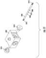
- FIG. 8illustrates a second exemplary valve system.
- FIG. 9illustrates an exploded view of the valve system of FIG. 8 .
- FIG. 10illustrates a third exemplary valve system (or valve or valve component).
- FIG. 11illustrates an exploded view of a portion of the valve system.
- FIG. 12illustrates a cross-sectional side view of a portion of the valve system depicted in FIG. 11 .
- FIG. 13illustrates a close-up view of an exemplary septum of the valve system.
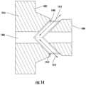
- FIG. 14illustrates a cross-sectional side view of an exemplary septum of the valve system, such as the septum example depicted in FIG. 13 .
- FIG. 15illustrates alternative configurations of an example septum of the valve system such as the example septum depicted in FIG. 13 .
- FIGS. 16 - 19illustrate example operations of the valve system depicted in FIG. 11 .
- valves and/or valve systemsthat operate without displacing fluid.
- the provided valvesmay be operated with a low actuation force and may be made to be relatively small (e.g., on a micro or miniature scale) to accommodate use within a wearable drug delivery device or pump system.
- Other examplesare also disclosed.
- valvesDisclosed herein are one or more valve systems, components, and methods of use that solve one or more drawbacks of conventional valves, including those drawbacks described above.
- the disclosed valvesmay be made small with relatively few pieces and may be used in a wearable drug delivery device (e.g., drug delivery pump) to provide a liquid drug to a user.
- a wearable drug delivery devicee.g., drug delivery pump
- valves disclosed hereinmay use a septum or septa.
- septaallows for the use of lower durometer materials than may be used with a conventional O-ring based pump system.
- the amount of compressionmay be controlled by the diameter of the tube instead of the tube, the inner diameter (ID) and outer diameter (OD) of an O-ring, and the barrel.
- valvessolve the issues related to traditional O-ring seals at the micro/miniature scale.
- Process limitations of moldingdo not allow the molding tolerances of O-rings to scale proportionally as size is reduced. This may lead to much wider ranges of compression and thus increased ranges of force to actuate an O-ring seal as the size of the valve is reduced.
- Compounding the issueis the need for multiple seals to create non-displacing valves (a valve that does not change volume when actuated).
- valvesmay use a side ported tube pierced through a septum or septa to create a low force, non-displacement, micro-miniature valve. By piercing through the septum or septa, the amount of seal force is more controlled than with an O-ring.
- FIG. 1illustrates a first exemplary valve system (or valve or valve component) 100 .
- the valve system 100may include a valve body 102 , an inlet component 104 , an outlet component 106 , and a valve tube 108 .
- the valve body 102may be formed from silicone or may be formed from other compatible elastomeric material.
- the valve body 102may be formed as a single molded piece or component, or as multiple molded pieces or components.
- the inlet component 104may be a rigid tubing component that may be placed (as in a compression fit) into the valve body 102 or may be a tubing component bonded to the valve body 102 .
- the outlet component 106may be a rigid tubing component that may be placed into the valve body 102 or may be a tubing component bonded to the valve body 102 .
- the valve tube 108may be a rigid tubing component.
- the valve tube 108may be positioned (e.g., pierced) through the valve body 102 to create seals between the valve tube 108 and the inlet component 104 and/or the outlet component 106 .
- the valve tube 108may include an opening and may be moved back and forth within the valve body 102 as described further herein.
- the valve tube 108may include a closed end 110 .
- the closed end 110may be crimped, welded, formed, capped, and/or filled.
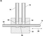
- FIG. 2illustrates a cross-sectional side view of the valve system 100 .
- the valve system 100may include a first opening or void 202 and a second opening or void 204 .
- the first void 202may be coupled or connected to the inlet component 104 .
- the second void 204may be coupled or connected to the outlet component 106 .
- the valve tube 108may include a side port 206 .
- the side port 206may comprise one or more openings (e.g., aligned openings) in the valve tube 108 .
- the side port 206may be formed using a grinding method, a laser cutting process, a machining process, or may be part of the original forming process for the valve tube 108 (e.g., through a molding process).
- the valve body 102may be considered to be a septum (or septa). As is shown in FIG. 2 , the valve tube 108 may, for example, be pierced through the septum (e.g., valve body 102 ) stretching the septum over the valve tube 108 to create a seal.
- the valve body 102may include the voids 202 and 204 , connected to the inlet and outlet components 104 and 106 , respectively, where no seal to the valve tube 108 is provided.
- the valve tube 108may be connected to a pump head (not shown in FIG. 2 ) that may either draw a fluid in through the side port 206 (from the inlet component 104 ) or push the fluid out through the side port (through the outlet component 106 ).
- the valve system 100may function by being operable to move the side port 206 of the valve tube 108 between the voids 202 and 204 to connect and disconnect the pump head from the inlet and outlet components 104 and 106 as appropriate.
- a pump(not shown in FIG. 2 ) could also or alternatively be coupled to the valve tube 108 .
- a direction of movement of the valve tube 108 within the valve body 102is shown by 208 .
- the valve tube 108may be moved linearly in the directions shown by 208 through the valve body 102 .
- the movement of the valve tube 108may cause the side port 206 to change between being exposed to the inlet component 104 and the outlet component 106 .
- the side port 206may be completely closed off from the inlet component 104 and the outlet component 106 to prevent any unintended flow of fluid.
- the valve system 100may be used within or as part of a drug delivery device including, for example, a wearable drug delivery device.
- the inlet component 104may be coupled to a reservoir storing a liquid drug or any liquid therapeutic agent (or any fluid).
- the outlet component 106may be coupled to fluid path (e.g., including a cannula) that is coupled to a user or patient such that the liquid drug stored in the reservoir may be delivered to the user.
- the liquid drugmay be insulin and the valve system 100 may be part of a wearable insulin drug delivery device or system.
- the valve system 100may be operable to pump in and/or pump out fluid without unintended fluid flow by maintaining a constant volume during transitions of coupling the side port 206 to either the inlet component 104 or the outlet component 106 .
- the valve system 100may be applied to a fluid path requiring various path separations.
- the valve system 100may include dual inlets and a single outlet and/or more voids or open spaces may be added to increase the number of valve stations. Any number of voids, valve stations, inlet, and/or outlet components may be accommodated.
- FIG. 3may represent a cross-sectional side view of a delivery system 300 .
- the delivery system 300may include the valve system 100 .
- the delivery system 300may further include a pump head component 302 coupled to the valve system 100 .
- the pump head component 302may include a pump chamber 304 and a pump piston 306 .
- FIG. 3illustrates the delivery system 300 in a first or initial stage of operation.
- the delivery system 300is ready to fill the pump chamber 304 with a fluid.
- the valve tube 108may be coupled to the pump chamber 304 .
- the inlet component 104may be coupled to a reservoir storing the fluid (not shown in this example).
- the outlet component 106may be coupled to a cannula and/or other fluid path that is coupled to a user.
- the side port 206is aligned with/open to the inlet component 104 and is closed to the outlet component 106 .
- FIG. 4illustrates a second stage of operation of the delivery system 300 (subsequent to the stage of operation of the delivery system 300 as shown in FIG. 3 ).
- the valve tube 108may be operable to move to a first position within the valve body 102 to align the side port 206 to the inlet component 104 when fluid is available to the inlet component (e.g., fluid may be stored in an external reservoir (not shown) coupled to the inlet component) is to be drawn into the inlet component.
- the pump piston 306is moved in a direction 402 .
- the movement of the pump piston 306causes fluid to be drawn into the pump chamber 304 —through the inlet component 104 , through the valve tube 108 , and into the pump chamber 304 —as shown by arrow flow indicators 404 . As a result, all or a portion of the pump chamber 304 may be filled with the fluid.
- the pump piston 306may operable to be moved by any suitable actuation system.
- FIG. 5illustrates a third stage of operation of the delivery system 300 (subsequent to the stage of operation of the delivery system 300 as shown in FIG. 4 ).
- the valve tube 108is operable to move in a direction 502 .
- the movement of the valve tube 108may cause the side port 206 to be aligned with/open to the outlet component 106 (e.g., at a second position) and be closed to the inlet component 104 .
- FIG. 6illustrates a fourth stage of operation of the delivery system 300 (subsequent to the stage of operation of the delivery system 300 as shown in FIG. 5 ).
- the pump piston 306is moved in a direction 602 that aligns the side port 206 with outlet component 106 .
- the movement of the pump piston 306causes fluid to be pushed in the direction (shown by directional arrows 604 ) from the pump chamber 304 for delivery—i.e., from the pump chamber 304 , through the valve tube 108 , and through the outlet component 106 (as indicated by the directional arrows 604 ) (and on to a cannula and/or fluid path for delivery to the user).
- FIG. 7illustrates a fifth stage of operation of the delivery system 300 (subsequent to the stage of operation of the delivery system 300 as shown in FIG. 6 ).
- the side port 206is realigned with the inlet component 104 to return to the state of operation shown in FIG. 3 .
- the delivery system 300may repeat the steps illustrated in FIGS. 3 - 7 (or a portion thereof) to implement a subsequent cycle of drawing in the fluid to the pump chamber 304 from the reservoir and pushing it out for delivery to a patient.
- the valve body 102may be moved along the valve tube 108 to align the side port 206 appropriately with the outlet component 106 .
- the valve body 102may be configured and operable to be moved to a first position with respect to the valve tube 108 to align the side port 206 to the inlet component 104 when fluid is available to the inlet component 104 (e.g., stored in an external reservoir coupled to the inlet component 104 ) to be drawn into the inlet component 104 .
- the valve body 102may be configured and operable to be moved to a second position with respect to the valve tube 108 to align the side port 206 to the outlet component 106 when fluid is to be pushed out of the valve system 100 to the outlet component 106 for delivery of the fluid.
- the valve tube 108 and/or the valve body 102may be moved by any suitable actuation system.
- FIG. 8illustrates a second exemplary valve system (or valve or valve component) 800 .
- the valve system 800may include a first seal body component 802 , a second seal body component 804 , a third seal body component 806 , and a fourth seal body component 808 . Positioned between the seal body components may be a first septum 810 , a second septum 812 , and a third septum 814 .
- the valve system 800may further include an inlet component 816 , an outlet component 818 , and a valve tube 820 .
- the valve tube 820may include an opening 822 .
- the inlet component 816may, for example, be coupled to a reservoir.
- the outlet component 818may, for example, be coupled to a fluid path coupled to a user.
- the valve system 800may be coupled to a pump head (not shown in FIG. 8 ) that may be used to draw in and push out fluid in a manner similar to the operation of valve system 100 .
- the valve tube 820may be moved through the septa 810 - 814 and the openings/air cavities of the seal body components 802 - 808 to couple the opening 822 to the inlet component 816 or to the outlet component 818 to draw in fluid from a reservoir and/or push out fluid for delivery to a user.
- FIG. 9illustrates an exploded view of the valve system 800 .
- FIG. 9shows the arrangement of the components of the valve system 800 .
- the seal bodies 802 - 808may be rigid components.
- the septa 810 - 814may be a soft material and/or compressible material.
- the seal bodies 802 - 808may be arranged such that the interior openings or cavities may be aligned.
- the valve tube 820may be of any shape and may be positioned through the openings of the seal bodies 802 - 808 and the septa 810 - 814 .
- FIG. 10illustrates a third exemplary valve system 1000 .
- the valve system 1000includes a valve body 1002 and a side ported tube component 1004 .
- the valve body 1002may be formed by injection molded thermoplastic.
- the side ported tube 1004may include a first opening or side port 1006 , a second opening or side port 1008 , and a plug 1010 .
- the side ported tube 1004may be a rigid tubing placed into the valve body 1002 .
- the valve body 1002may be considered to be a pump block of the valve system 1000 .
- the plug 1010may be installed into the tube 1004 as a separate piece or component from the tube 1004 or may be formed through spot-weld process, a crimping process, a swaging process, a filling/plugging process, any combination thereof, or the like.
- a first portion of the tube 1004may be or may form an inlet component 1012 of the tube 1004 .
- a second portion of the tube 1004may be or may form an outlet component 1014 of the tube 1004 .
- the plug 1010may help prevent fluid flowing through (e.g., by a liquid drug) between the inlet component 1012 and the outlet component 1014 .
- the inlet component 1012may be coupled to a reservoir storing a liquid drug or other therapeutic agent and the outlet component 1014 may be coupled to a fluid path (e.g., a cannula) coupled to a patient.
- a fluid pathe.g., a cannula
- the tube 1004may be formed of two or more tubes.
- the tube 1004may be formed of two separate tubes having end caps joined together to form the plug 1010 and capable of moving together as a single component.
- the valve system 1000may further include a first septum component 1016 and a second septum component 1018 .
- the first septum 1016 and the second septum 1018may each be formed from liquid silicone rubber or other compatible elastomeric material.
- the first septum 1016 and the second septum 1018may each be formed (e.g., molded) as a single component or piece or as multiple components or pieces.
- the first septum 1016 and the second septum 1018may each be pierced by the tube 1004 .
- the valve system 1000may further include a first piston 1020 (e.g., a left piston based on the orientation of the valve system 1000 as depicted in FIG.
- first and second pistons 1020 and 1022may be moved (e.g., linearly) within a first piston pump chamber 1024 and a second piston pump chamber 1026 , respectively.
- components of the valve system 1000may be arranged in a symmetrical manner.
- the first septum 1016 and the second septum 1018may be aligned along a first axis and the pistons 1020 and 1022 may be aligned along a second axis, perpendicular to the first axis.
- the arrangement of the components of the valve system 1000may form a low force, non-displacement, micro/miniature valve.
- the valve system 1000may provide a cross-flow valve that provide a two position, four-way ported valve that may alternatively connect the pump chambers 1024 and 1026 to the inlet component 1012 and the outlet component 1014 of the valve body 1002 .
- the amount of seal forcemay be more controlled than with an O-ring as described herein.
- the septa 1016 and 1018may form radial seals with the valve body 1002 .
- Each septum 1016 and 1018may include two radial sealing faces to the valve body 1002 separated with an opening or through-hole (e.g., a void) where no seal to the tube 1004 is provided.
- the voidsmay create openings that may provide fluid channels to the side ported tube 1004 .
- the voids and design of the valve body 1002may create separate fluid channels coupling the piston pump chambers 1024 and 1026 and the inlet and outlet components 1012 and 1014 , based on the position of the valve tube 1004 .
- the valve system 1000may operate by actuating/moving the side ported tube 1004 to the correct position along each septum 1016 and 1018 prior to movement of the pistons 1020 and 1022 (e.g., prior to a stroke of the pistons 1020 and 1022 ), thereby appropriately connecting and/or disconnecting the proper piston 1020 and 1022 from the inlet or outlet component 1012 and 1014 as described in more detail herein.
- FIG. 11illustrates an exploded view of a portion of the valve system 1000 .
- FIG. 11illustrates an arrangement of the pump block 1102 , the septa 1016 and 1018 , and the side ported tube 1004 (the side ported tube 1004 may also be referred to as a needle).
- the septa 1016 and 1018are each represented as single piece components.
- the side ported tube 1004may be installed through the septa 1016 and 1018 .
- valve body 1002 and the septa 1016 and 1018may be stationary or held fixed as the side ported tube 1004 is actuated or moved.
- the side ported tube 1004may be moved linearly through the septa 1016 and 1018 and the valve body 1002 .
- Linear actuation of the tube 1004allows the side ports 1006 and 1008 to change connections between the piston pump chambers 1024 and 1026 (not shown in FIG. 11 ) and the inlet and outlet components 1012 and 1014 . Because the tube 1004 is plugged by plug 1010 between the two side ports 1006 and 1008 , there is no connection between the inlet component 1012 and outlet component 1014 of the tube 1004 during operation which prevents unintended drug delivery.
- FIG. 12illustrates a cross-sectional side view of a portion of the valve system 1000 (e.g., the portion of the valve system 1000 depicted in FIG. 11 ).
- FIG. 12shows the fluid path provided within the valve system 1000 between the side ported tube 1004 and the piston pump chambers 1024 and 1026 (not shown in FIG. 12 ).
- the design and arrangement of the septa 1016 and 1018may provide fluidic connections between channels within the valve body 1002 and the channel provided by the tube 1004 (e.g., the internal open areas of the tube 1004 ).
- the septa 1016 and 1018also provide for two distinct face seals with the valve body 1002 to prevent any fluid from leaking from the valve system 1000 . In turn, this allows the side ported tube 1004 to have access to the pump chambers 1024 and 1026 .
- the side port 1006may be coupled to the pump chamber 1026 .
- fluidmay be drawn into the valve system 1000 (e.g., from an external reservoir or other fluid holding device) from the inlet component 1012 and through the side port 1006 as shown by flow arrows 1202 .
- the flow arrows 1202show that fluid may be drawn into the pump chamber 1026 and any channel in the valve body 1002 coupled to the pump chamber 1026 .
- the side port 1008may be coupled to the pump chamber 1024 .
- fluidmay be pushed out of the valve system 1000 (e.g., to an external fluid path and/or cannula coupled to a patient) from the side port 1008 to the outlet component 1014 as shown by flow arrows 1204 .
- the flow arrows 1204show that fluid may be pushed out of the pump chamber 1024 and any channel in the valve body 1002 coupled to the pump chamber 1024 .
- FIG. 13illustrates a close-up view of an example septum of the valve system 1000 —for example, the septum 1016 .
- FIG. 14illustrates a cross-sectional side view of an exemplary septum of the valve system 1000 —for example, the septum 1016 depicted in FIG. 13 .
- the septum 1016may include a first radial face seal 1402 (to the valve body 1002 ) and a second radial face seal 1404 (also to the valve body 1002 ).
- the septum 1016may include an inner open area or channel 1406 as well as a first angled opening or channel 1408 and a second angled opening or channel 1410 coupled to the inner channel 1406 .
- Fluidmay flow bidirectionally through the channel 1408 as indicated by flow indicator 1412 into the side ported tube 1004 depending on the position of the tube 1004 .
- fluidmay flow bidirectionally through the channel 1410 as indicated by flow indicator 1414 into the side ported tube 1004 depending on the position of the tube 1004 .
- FIG. 15illustrates example configurations of an exemplary septum of the valve system 1000 —for example, the septum 1016 .
- Septum 1016 - 1illustrates the septum 1016 formed as multiple pieces or components.
- Septum 1016 - 2illustrates the septum 1016 formed as a single piece or component.
- FIGS. 16 - 19illustrate operation of the valve system 1000 . Specifically, FIGS. 16 - 19 illustrate a sequence of operations for drawing in and pumping out a portion of a fluid by the valve system 1000 for delivery to a patient.
- FIG. 16illustrates the valve system 1000 in a first or initial stage of operation.
- the tube 1004is actuated to move in a direction 1602 to set the side ports 1006 and 1008 in appropriate positions for valving.
- the tube 1004is moved to position the side port 1006 (i.e., the side port connected to the inlet component 1012 ) to be coupled to the piston 1020 /piston pump chamber 1024 (e.g., the left side piston as indicated in FIG. 16 ).
- the side port 1008i.e., the side port coupled to the outlet component 1014
- the side ports 1006 and 1008may be coupled to the piston pump chambers 1024 and 1026 , respectively, through the flow channels in the septa 1016 and 1018 as described herein. As shown in FIG. 16 , a portion of a fluid 1604 is positioned in the valve system 1000 and occupies a portion of the flow channels formed in and/or coupled to the septa 1016 and 1018 and the piston pump chamber 1026 .
- the piston pump chamber 1024 (and any coupled channel)may be empty or devoid of any, or substantially any, fluid.
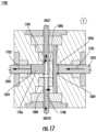
- FIG. 17illustrates a second stage of operation of the valve system 1000 (subsequent to the stage of operation of the valve system 1000 as shown in FIG. 16 ).
- the pistons 1020 and 1022are both operable to be actuated (e.g., in unison) to move in a direction 1702 .
- fluid 1706may be draw in from the inlet component 1012 to the pump chamber 1024 .
- the stored fluid 1604e.g., the same fluid as the fluid 1706 but referenced separately to distinguish locations of the fluids
- the radial seals of the septa 1016 and 1018may provide sealing against the pumping pressures along with the fluidic channels positioned between the tube 1004 and the pump chambers 1024 and 1026 .
- FIG. 18illustrates a third stage of operation of the valve system 1000 (subsequent to the stage of operation of the valve system 1000 as shown in FIG. 17 ).
- the tube 1004is actuated to move in a direction 1802 .
- the tube 1004is moved to position the side port 1006 (i.e., the side port connected to the inlet component 1012 ) to be coupled to the piston 1022 /piston chamber 1026 .
- the side port 1008i.e., the side port coupled to the outlet component 1014
- the fluid 1706 drawn in during the prior operational stepis positioned within the pump chamber 1024 .
- the pump chamber 1026may be devoid of any, or substantially any, fluid.
- FIG. 19illustrates a fourth stage of operation of the valve system 1000 (subsequent to the stage of operation of the valve system 1000 as shown in FIG. 18 ).
- the pistons 1020 and 1022are both actuated (e.g., in unison) to move in a direction 1902 .
- fluid 1906may be draw in from the inlet component 1012 to the pump chamber 1026 .
- the stored fluid 1706e.g., the same fluid as the fluid 1906 but referenced separately to distinguish locations of the fluids
- the outlet component 1014may be pushed or pumped out through the outlet component 1014 .
- the valve system 1000may repeat the steps illustrated in FIGS. 16 - 19 to implement a subsequent cycle of drawing in the fluid into the valve system 1000 from the reservoir and pushing it out for delivery to a patient.
- Each example described hereinmay be part of a drug delivery system including, for example, a wearable drug delivery system.
Landscapes
- Engineering & Computer Science (AREA)
- Health & Medical Sciences (AREA)
- General Engineering & Computer Science (AREA)
- Heart & Thoracic Surgery (AREA)
- Mechanical Engineering (AREA)
- Life Sciences & Earth Sciences (AREA)
- Anesthesiology (AREA)
- Biomedical Technology (AREA)
- Hematology (AREA)
- Animal Behavior & Ethology (AREA)
- General Health & Medical Sciences (AREA)
- Public Health (AREA)
- Veterinary Medicine (AREA)
- Dispersion Chemistry (AREA)
- Chemical & Material Sciences (AREA)
- Pulmonology (AREA)
- Vascular Medicine (AREA)
- Physics & Mathematics (AREA)
- Automation & Control Theory (AREA)
- General Physics & Mathematics (AREA)
- Infusion, Injection, And Reservoir Apparatuses (AREA)
- Nozzles (AREA)
Abstract
Description
Claims (17)
Priority Applications (2)
| Application Number | Priority Date | Filing Date | Title |
|---|---|---|---|
| US16/514,183US11725741B2 (en) | 2018-07-17 | 2019-07-17 | Low force valves for drug delivery pumps |
| US18/338,411US12429141B2 (en) | 2018-07-17 | 2023-06-21 | Low force valves for drug delivery pumps |
Applications Claiming Priority (2)
| Application Number | Priority Date | Filing Date | Title |
|---|---|---|---|
| US201862699022P | 2018-07-17 | 2018-07-17 | |
| US16/514,183US11725741B2 (en) | 2018-07-17 | 2019-07-17 | Low force valves for drug delivery pumps |
Related Child Applications (1)
| Application Number | Title | Priority Date | Filing Date |
|---|---|---|---|
| US18/338,411DivisionUS12429141B2 (en) | 2018-07-17 | 2023-06-21 | Low force valves for drug delivery pumps |
Publications (2)
| Publication Number | Publication Date |
|---|---|
| US20200025310A1 US20200025310A1 (en) | 2020-01-23 |
| US11725741B2true US11725741B2 (en) | 2023-08-15 |
Family
ID=67480465
Family Applications (2)
| Application Number | Title | Priority Date | Filing Date |
|---|---|---|---|
| US16/514,183Active2041-06-15US11725741B2 (en) | 2018-07-17 | 2019-07-17 | Low force valves for drug delivery pumps |
| US18/338,411Active2039-07-30US12429141B2 (en) | 2018-07-17 | 2023-06-21 | Low force valves for drug delivery pumps |
Family Applications After (1)
| Application Number | Title | Priority Date | Filing Date |
|---|---|---|---|
| US18/338,411Active2039-07-30US12429141B2 (en) | 2018-07-17 | 2023-06-21 | Low force valves for drug delivery pumps |
Country Status (7)
| Country | Link |
|---|---|
| US (2) | US11725741B2 (en) |
| EP (1) | EP3824182B1 (en) |
| JP (2) | JP7307147B2 (en) |
| CN (1) | CN112437838B (en) |
| AU (2) | AU2019308251B2 (en) |
| CA (1) | CA3105175A1 (en) |
| WO (1) | WO2020018642A1 (en) |
Families Citing this family (3)
| Publication number | Priority date | Publication date | Assignee | Title |
|---|---|---|---|---|
| CN113289225B (en)* | 2021-05-31 | 2023-10-31 | 刘焕林 | Uropoiesis surgery postoperative medicine feeding device |
| US12044342B2 (en) | 2021-12-28 | 2024-07-23 | Cytiva Us Llc | Fluid connector with slidable member |
| US12031654B2 (en)* | 2021-12-28 | 2024-07-09 | Cytiva Us Llc | Fluid connector |
Citations (141)
| Publication number | Priority date | Publication date | Assignee | Title |
|---|---|---|---|---|
| US1441508A (en) | 1921-12-06 | 1923-01-09 | Jensen Anton Marius | Cylindrical slide valve |
| GB357139A (en) | 1929-06-14 | 1931-09-14 | Paul Von Vago | |
| GB810488A (en) | 1955-03-01 | 1959-03-18 | Eduard Woydt | Liquid pressure piston-engine or reciprocating pump |
| US3552441A (en)* | 1967-09-26 | 1971-01-05 | Hartmut Luhleich | Piercable closure diaphragm for a chamber |
| US3579805A (en) | 1968-07-05 | 1971-05-25 | Gen Electric | Method of forming interference fits by heat treatment |
| FR2096275A5 (en) | 1970-06-13 | 1972-02-11 | Ismatec Sa | |
| US4833088A (en) | 1987-09-25 | 1989-05-23 | Miles Inc. | Reagent strip handling mechanism |
| US5232668A (en) | 1991-02-27 | 1993-08-03 | Boehringer Mannheim Corporation | Test strip holding and reading mechanism for a meter |
| US5244459A (en) | 1992-01-28 | 1993-09-14 | Hill Raymond R | Suction irrigator endoscope |
| US5995236A (en) | 1998-04-13 | 1999-11-30 | Mit Development Corporation | Blood fluid characteristics analysis instrument |
| US6142181A (en)* | 1998-02-11 | 2000-11-07 | Daimlerchrysler Ag | 3/3-way valve |
| US6200293B1 (en) | 1997-08-27 | 2001-03-13 | Science Incorporated | Fluid delivery device with temperature controlled energy source |
| US6418332B1 (en) | 1999-02-25 | 2002-07-09 | Minimed | Test plug and cable for a glucose monitor |
| US6514460B1 (en) | 1999-07-28 | 2003-02-04 | Abbott Laboratories | Luminous glucose monitoring device |
| US6740059B2 (en) | 2000-09-08 | 2004-05-25 | Insulet Corporation | Devices, systems and methods for patient infusion |
| US20040116847A1 (en) | 2002-09-12 | 2004-06-17 | Children's Hospital Medical Center | Method and device for painless injection of medication |
| US6768425B2 (en) | 2000-12-21 | 2004-07-27 | Insulet Corporation | Medical apparatus remote control and method |
| US20050009126A1 (en) | 2003-06-12 | 2005-01-13 | Therasense, Inc. | Method and apparatus for providing power management in data communication systems |
| US20050125162A1 (en) | 2003-12-03 | 2005-06-09 | Kiamars Hajizadeh | Multi-sensor device for motorized meter and methods thereof |
| US20050201897A1 (en) | 2002-11-26 | 2005-09-15 | Volker Zimmer | Body fluid testing device |
| US20050232815A1 (en) | 2002-12-23 | 2005-10-20 | Werner Ruhl | Body fluid testing device |
| US20050238507A1 (en) | 2002-04-23 | 2005-10-27 | Insulet Corporation | Fluid delivery device |
| US20050277164A1 (en) | 2001-04-02 | 2005-12-15 | Therasense, Inc. | Blood glucose tracking apparatus and methods |
| WO2007084214A1 (en) | 2006-01-20 | 2007-07-26 | Smiths Medical Asd, Inc. | Shuttle valve |
| WO2007092618A2 (en) | 2006-02-09 | 2007-08-16 | Deka Products Limited Partnership | Fluid delivery systems and methods |
| US7303549B2 (en) | 2002-04-23 | 2007-12-04 | Insulet Corporation | Transcutaneous fluid delivery system |
| US20090204078A1 (en)* | 2008-02-13 | 2009-08-13 | Boston Scientific Scimed, Inc. | Manifold and Valve Seal for Use with a Medical Device |
| US20090254041A1 (en) | 2006-06-06 | 2009-10-08 | Krag Christian Roege | Assembly Comprising Skin-Mountable Device and Packaging Therefore |
| US20090282947A1 (en) | 2008-05-13 | 2009-11-19 | Mark Powell | Encoder device and gapping and centering device for an encoder device |
| US20100152658A1 (en) | 2008-12-16 | 2010-06-17 | Medtronic Minimed, Inc. | Needle insertion systems and methods |
| US20100168683A1 (en) | 2008-12-30 | 2010-07-01 | Oz Cabiri | Needle assembly for drug pump |
| US7842241B2 (en) | 2006-12-26 | 2010-11-30 | Abbott Diabetes Care Inc. | Analyte meter protectors and methods |
| US20100317951A1 (en) | 2009-06-11 | 2010-12-16 | Roche Diagnostics Operations, Inc. | Portable handheld medical diagnostic devices with color-changing indicator |
| US20110071765A1 (en) | 2008-05-16 | 2011-03-24 | Ofer Yodfat | Device and Method for Alleviating Postprandial Hyperglycemia |
| US20110193704A1 (en) | 2009-08-31 | 2011-08-11 | Abbott Diabetes Care Inc. | Displays for a medical device |
| US8003052B2 (en) | 2006-06-27 | 2011-08-23 | Roche Diagnostics Operation, Inc. | Diagnostic tape cassette |
| US20110218495A1 (en) | 2008-03-03 | 2011-09-08 | Roche Diagnostics International Ag | Insulin pump with replacement capabilities |
| US20110289497A1 (en) | 2010-05-24 | 2011-11-24 | Abbott Diabetes Care Inc. | Method and System for Updating a Medical Device |
| US20120095316A1 (en) | 2010-10-15 | 2012-04-19 | Roche Diagnostic Operations, Inc. | Handheld diabetes managing device with light pipe for enhanced illumination |
| US20120201048A1 (en) | 2011-02-03 | 2012-08-09 | Bayer Healthcare Llc | Component illumination apparatus, systems, and electronic devices and methods of manufacturing and using same |
| USD674400S1 (en) | 2009-09-14 | 2013-01-15 | Microsoft Corporation | Display screen with user interface |
| US8465977B2 (en) | 2008-07-22 | 2013-06-18 | Roche Diagnostics Operations, Inc. | Method and apparatus for lighted test strip |
| USD685083S1 (en) | 2012-04-13 | 2013-06-25 | Becton, Dickinson And Company | Infusion device |
| USD687141S1 (en) | 2012-04-13 | 2013-07-30 | Becton, Dickinson And Company | Infusion device |
| USD687536S1 (en) | 2012-04-13 | 2013-08-06 | Becton, Dickinson And Company | Infusion device |
| US20130204130A1 (en)* | 2012-02-03 | 2013-08-08 | Merit Medical Systems, Inc. | Devices, systems and methods for carbon dioxide angiography |
| USD692552S1 (en) | 2011-11-08 | 2013-10-29 | Becton Dickinson France, S.A.S. | Microinfuser |
| US20140012119A1 (en) | 2012-06-07 | 2014-01-09 | Chris Geaghan | Skin adhesive template |
| US20140054883A1 (en) | 2012-03-07 | 2014-02-27 | Deka Products Limited Partnership | Infusion Pump Assembly |
| US20140074033A1 (en) | 2011-02-09 | 2014-03-13 | Becton ,Dickinson and Company | Insulin Infusion Set |
| US20140078263A1 (en) | 2012-09-18 | 2014-03-20 | Samsung Techwin Co., Ltd. | Monitoring apparatus and system using 3d information of images and monitoring method using the same |
| US20140131199A1 (en) | 2008-07-17 | 2014-05-15 | Abbott Diabetes Care Inc. | Analyte Measurement Devices and Systems, and Components and Methods Related Thereto |
| US20140148784A1 (en) | 2011-04-21 | 2014-05-29 | Abbvie Inc. | Wearable automatic injection device for controlled administration of therapeutic agents |
| US20140254170A1 (en) | 2013-03-11 | 2014-09-11 | Roche Diagnostics Operations, Inc. | Blood glucose test strip illumination device and method |
| US20140296787A1 (en) | 2011-09-02 | 2014-10-02 | Unitract Syringe Pty Ltd | Drive mechanism for drug delivery pumps with integrated status indication |
| US20140316379A1 (en) | 2011-12-07 | 2014-10-23 | Becton, Dickinson And Company | Needle shielding assemblies and infusion devices for use therewith |
| USD733740S1 (en) | 2013-03-13 | 2015-07-07 | Samsung Electronics Co., Ltd. | Display screen or portion thereof with animated graphical user interface |
| US20150283335A1 (en) | 2014-04-07 | 2015-10-08 | Medtronic Minimed, Inc. | Waterproof indicator and method of use thereof |
| USD741871S1 (en) | 2013-05-29 | 2015-10-27 | Microsoft Corporation | Display screen with graphical user interface |
| US20150338349A1 (en) | 2014-05-20 | 2015-11-26 | Roche Diagnostics Operations Inc. | bG METER ILLUMINATED TEST STRIP |
| USD745142S1 (en) | 2012-08-30 | 2015-12-08 | Unitract Syringe Pty Ltd | Drug delivery pump |
| US20150361154A1 (en) | 2013-01-15 | 2015-12-17 | Phasebio Pharmaceuticals, Inc. | Therapeutic agents, compositions, and methods for glycemic control |
| US20150366945A1 (en) | 2014-06-20 | 2015-12-24 | Howard E. Greene | Infusion delivery devices and methods |
| US20160015891A1 (en) | 2012-06-18 | 2016-01-21 | Fresenius Kabi Deutschland Gmbh | Port cannula system for puncturing port catheters |
| USD748664S1 (en) | 2013-07-19 | 2016-02-02 | Robert Bosch Gmbh | Display screen with a graphical user interface |
| US20160038689A1 (en) | 2013-03-15 | 2016-02-11 | Amgen Inc. | Body contour adaptable autoinjector device |
| US20160058941A1 (en) | 2013-05-03 | 2016-03-03 | Becton Dickinson And Company | Drug delivery device |
| USD752607S1 (en) | 2014-06-17 | 2016-03-29 | Tencent Technology (Shenzhen) Company Limited | Display screen or portion thereof with animated graphical user interface |
| USD754181S1 (en) | 2013-12-12 | 2016-04-19 | Tencent Technology (Shenzhen) Company Limited | Display screen portion with graphical user interface |
| US20160135747A1 (en) | 2014-11-14 | 2016-05-19 | Roche Diabetes Care, Inc. | Skin-mountable medical device |
| USD760272S1 (en) | 2014-04-30 | 2016-06-28 | Tencent Technology (Shenzhen) Company Limited | Portion of a display screen with graphical user interface |
| USD762702S1 (en) | 2014-08-28 | 2016-08-02 | Microsoft Corporation | Display screen with transitional graphical user interface |
| USD766264S1 (en) | 2014-11-19 | 2016-09-13 | Qcue, Inc. | Display screen with graphical user interface for presenting ticket pricing |
| USD768188S1 (en) | 2014-04-08 | 2016-10-04 | Huawei Device Co., Ltd. | Display screen or portion thereof with graphical user interface |
| US20160310665A1 (en) | 2013-12-20 | 2016-10-27 | Becton, Dickinson And Company | Infusion Set Adhesive Systems |
| USD774640S1 (en) | 2015-07-30 | 2016-12-20 | Becton, Dickinson And Company | Medical injector |
| USD776262S1 (en) | 2015-07-30 | 2017-01-10 | Becton, Dickinson And Company | Medical injector |
| USD776265S1 (en) | 2015-07-30 | 2017-01-10 | Becton, Dickinson And Company | Medical injector |
| USD776264S1 (en) | 2015-07-30 | 2017-01-10 | Becton, Dickinson And Company | Medical injector |
| US20170028132A1 (en) | 2013-12-01 | 2017-02-02 | Becton, Dickinson And Company | Medicament Device |
| USD779526S1 (en) | 2015-04-13 | 2017-02-21 | Gt Gettaxi Limited | Display screen or portion thereof with graphical user interface |
| US9572926B2 (en) | 2009-09-15 | 2017-02-21 | Medimop Medical Projects Ltd. | Cartridge insertion assembly |
| USD779523S1 (en) | 2015-04-06 | 2017-02-21 | Domo, Inc. | Display screen or portion thereof with a graphical user interface for analytics |
| EP3135965A1 (en) | 2015-08-31 | 2017-03-01 | bNovate Technologies SA | Pump system with rotary valve |
| USD781302S1 (en) | 2014-10-31 | 2017-03-14 | Dell Products L.P. | Display screen with graphical user interface for an information handling system |
| USD784395S1 (en) | 2015-09-11 | 2017-04-18 | Under Armour, Inc. | Display screen with graphical user interface |
| USD791813S1 (en) | 2014-04-22 | 2017-07-11 | Google Inc. | Display screen with graphical user interface or portion thereof |
| USD794776S1 (en) | 2015-07-30 | 2017-08-15 | Becton, Dickinson And Company | Medical injector |
| US20170234858A1 (en) | 2016-01-18 | 2017-08-17 | Jana Care, Inc. | Mobile device based multi-analyte testing analyzer for use in medical diagnostic monitoring and screening |
| USD802011S1 (en) | 2016-05-04 | 2017-11-07 | ALYK, Inc. | Computer screen or portion thereof with graphical user interface |
| US9814832B2 (en) | 2011-09-02 | 2017-11-14 | Unl Holdings Llc | Drive mechanism for drug delivery pumps with integrated status indication |
| USD804019S1 (en) | 2016-09-26 | 2017-11-28 | West Pharmaceutical Services, Inc. | Injector device |
| USD804650S1 (en) | 2016-09-26 | 2017-12-05 | West Pharmaceutical Services, Inc. | Injector device |
| USD805187S1 (en) | 2016-09-26 | 2017-12-12 | West Pharmaceutical Services, Inc. | Injector device |
| USD805189S1 (en) | 2016-09-26 | 2017-12-12 | West Pharmaceutical Services, Inc. | Injector device |
| USD805186S1 (en) | 2016-09-26 | 2017-12-12 | West Pharmaceutical Services, Inc. | Injector device |
| USD805190S1 (en) | 2016-09-26 | 2017-12-12 | West Pharmaceutical Services, Inc. | Injector device |
| USD805188S1 (en) | 2016-09-26 | 2017-12-12 | West Pharmaceutical Services, Inc. | Injector device |
| US20170354785A1 (en) | 2016-06-09 | 2017-12-14 | Becton, Dickinson And Company | Actuator Assembly for Drug Delivery System |
| USD807389S1 (en) | 2016-01-22 | 2018-01-09 | Google Llc | Portion of a display screen with a changeable graphical user interface component |
| US20180015274A1 (en)* | 2015-01-09 | 2018-01-18 | Bayer Healthcare Llc | Multiple fluid delivery system with multi-use disposable set and features thereof |
| USD810278S1 (en) | 2009-09-15 | 2018-02-13 | Medimop Medical Projects Ltd. | Injector device |
| USD810122S1 (en) | 2015-12-15 | 2018-02-13 | Domo, Inc. | Display screen or portion thereof with a graphical user interface |
| US20180075200A1 (en) | 2016-09-09 | 2018-03-15 | Dexcom, Inc. | Systems and methods for cgm-based bolus calculator for display and for provision to medicament delivery devices |
| USD813380S1 (en) | 2016-08-05 | 2018-03-20 | Amgen Inc. | On-body injector |
| USD816698S1 (en) | 2016-11-10 | 2018-05-01 | Koninklijke Philips N.V. | Display screen with animated graphical user interface |
| USD817481S1 (en) | 2009-09-15 | 2018-05-08 | West Pharma. Services IL, Ltd. | Injector device |
| USD822692S1 (en) | 2016-06-14 | 2018-07-10 | Itt Manufacturing Enterprises Llc. | Display screen or portion thereof with graphical user interface |
| US20180207357A1 (en) | 2003-07-16 | 2018-07-26 | Michael Sasha John | Medical Drug Delivery Systems with Mixing Chamber |
| USD824933S1 (en) | 2016-01-15 | 2018-08-07 | Pearson Education, Inc. | Display screen with a graphical user interface |
| US20180236173A1 (en) | 2017-02-22 | 2018-08-23 | Insulet Corporation | Needle insertion mechanisms for drug containers |
| USD826956S1 (en) | 2017-06-08 | 2018-08-28 | Insulet Corporation | Display screen with a graphical user interface |
| US20180256815A1 (en) | 2017-03-07 | 2018-09-13 | Insulet Corporation | Very high volume user filled drug delivery device |
| USD831034S1 (en) | 2016-12-07 | 2018-10-16 | Intuit Inc. | Display device with an invoice tracker for a graphical user interface |
| US20180307515A1 (en) | 2014-10-06 | 2018-10-25 | Red Bend Software | Method and apparatus for controlling devices in a personal environment using a portable computing device |
| USD835663S1 (en) | 2017-01-23 | 2018-12-11 | Facebook, Inc. | Display screen or portion thereof with graphical user interface |
| USD836770S1 (en) | 2017-09-25 | 2018-12-25 | Insulet Corporation | Drug delivery device |
| USD837240S1 (en) | 2017-03-02 | 2019-01-01 | The Procter & Gamble Company | Display screen with graphical user interface |
| USD838359S1 (en) | 2016-09-21 | 2019-01-15 | Amgen Inc. | On-body injector |
| US20190022317A1 (en) | 2017-07-18 | 2019-01-24 | Becton, Dickinson And Company | Administration System, Delivery Device, and Notification Device for Communicating Status of a Medical Device |
| USD840531S1 (en) | 2015-12-11 | 2019-02-12 | Nuance Designs Of Ct, Llc | Wearable autoinjector |
| US20190091404A1 (en) | 2017-09-25 | 2019-03-28 | Insulet Corporation | Pre-filled cartridge-based drug delivery device |
| US20190132801A1 (en) | 2017-10-30 | 2019-05-02 | Dexcom, Inc. | Diabetes management partner interface for wireless communication of analyte data |
| USD849767S1 (en) | 2017-03-08 | 2019-05-28 | Google Llc | Display screen with graphical user interface |
| US20190167895A1 (en) | 2016-08-08 | 2019-06-06 | Unl Holdings Llc | Drug Delivery Device And Method For Connecting A Fluid Flowpath |
| USD851666S1 (en) | 2017-08-28 | 2019-06-18 | Adp, Llc | Display screen with animated graphical user interface |
| USD853416S1 (en) | 2016-06-15 | 2019-07-09 | Carnahan Group, Inc. | Display screen or portion thereof with graphical user interface |
| USD853427S1 (en) | 2018-03-28 | 2019-07-09 | Manitowoc Crane Companies, Llc | Mobile communication device display screen or portion thereof with graphical user interface |
| USD853426S1 (en) | 2018-03-28 | 2019-07-09 | Manitowoc Crane Companies, Llc | Mobile communication device display screen or portion thereof with graphical user interface |
| USD854559S1 (en) | 2016-12-07 | 2019-07-23 | Trading Technologies International, Inc. | Display panel with graphical user interface having an indicator |
| US20190240417A1 (en) | 2016-06-23 | 2019-08-08 | Tecpharma Licensing Ag | Segmented piston rod for a medication delivery device |
| USD856506S1 (en) | 2015-07-10 | 2019-08-13 | Unl Holdings Llc | Drug delivery pump |
| JP2019525276A (en) | 2016-05-02 | 2019-09-05 | デックスコム・インコーポレーテッド | System and method for providing a warning optimized for a user |
| WO2019195521A1 (en) | 2018-04-04 | 2019-10-10 | Cardiac Assist Holdings, Llc | Medical dressing removable adhesive strips |
| US20190321545A1 (en) | 2013-12-26 | 2019-10-24 | Tandem Diabetes Care, Inc. | Integration of infusion pump with remote electronic device |
| WO2019213493A1 (en) | 2018-05-04 | 2019-11-07 | Insulet Corporation | Safety constraints for a control algorithm-based drug delivery system |
| WO2019246381A1 (en) | 2018-06-22 | 2019-12-26 | Eli Lilly And Company | Insulin and pramlintide delivery systems, methods, and devices |
| EP3000497B1 (en) | 2014-09-29 | 2020-01-01 | Becton, Dickinson and Company | Cannula insertion detection |
| US20200197605A1 (en) | 2017-05-05 | 2020-06-25 | Eli Lilly And Company | Closed loop control of physiological glucose |
| US20200261643A1 (en) | 2016-10-25 | 2020-08-20 | Amgen Inc. | On-body injector |
| WO2021011738A1 (en) | 2019-07-16 | 2021-01-21 | Beta Bionics, Inc. | Blood glucose control system |
Family Cites Families (4)
| Publication number | Priority date | Publication date | Assignee | Title |
|---|---|---|---|---|
| US5147323A (en)* | 1991-03-08 | 1992-09-15 | Habley Medical Technology Corporation | Multiple cartridge syringe |
| DE102012102274B4 (en)* | 2012-03-19 | 2018-05-24 | B. Braun Melsungen Ag | piston pump |
| IT201600072149A1 (en)* | 2016-07-11 | 2018-01-11 | Leuco Spa | Pump to dispense a liquid. |
| US11280327B2 (en)* | 2017-08-03 | 2022-03-22 | Insulet Corporation | Micro piston pump |
- 2019
- 2019-07-17AUAU2019308251Apatent/AU2019308251B2/enactiveActive
- 2019-07-17USUS16/514,183patent/US11725741B2/enactiveActive
- 2019-07-17EPEP19746402.7Apatent/EP3824182B1/enactiveActive
- 2019-07-17CACA3105175Apatent/CA3105175A1/enactivePending
- 2019-07-17WOPCT/US2019/042160patent/WO2020018642A1/ennot_activeCeased
- 2019-07-17JPJP2021502587Apatent/JP7307147B2/enactiveActive
- 2019-07-17CNCN201980047408.5Apatent/CN112437838B/enactiveActive
- 2023
- 2023-06-21USUS18/338,411patent/US12429141B2/enactiveActive
- 2023-06-29JPJP2023107162Apatent/JP7617185B2/enactiveActive
- 2023-08-16AUAU2023216793Apatent/AU2023216793B2/enactiveActive
Patent Citations (163)
| Publication number | Priority date | Publication date | Assignee | Title |
|---|---|---|---|---|
| US1441508A (en) | 1921-12-06 | 1923-01-09 | Jensen Anton Marius | Cylindrical slide valve |
| GB357139A (en) | 1929-06-14 | 1931-09-14 | Paul Von Vago | |
| GB810488A (en) | 1955-03-01 | 1959-03-18 | Eduard Woydt | Liquid pressure piston-engine or reciprocating pump |
| US3552441A (en)* | 1967-09-26 | 1971-01-05 | Hartmut Luhleich | Piercable closure diaphragm for a chamber |
| US3579805A (en) | 1968-07-05 | 1971-05-25 | Gen Electric | Method of forming interference fits by heat treatment |
| FR2096275A5 (en) | 1970-06-13 | 1972-02-11 | Ismatec Sa | |
| US4833088A (en) | 1987-09-25 | 1989-05-23 | Miles Inc. | Reagent strip handling mechanism |
| US5232668A (en) | 1991-02-27 | 1993-08-03 | Boehringer Mannheim Corporation | Test strip holding and reading mechanism for a meter |
| US5244459A (en) | 1992-01-28 | 1993-09-14 | Hill Raymond R | Suction irrigator endoscope |
| US6200293B1 (en) | 1997-08-27 | 2001-03-13 | Science Incorporated | Fluid delivery device with temperature controlled energy source |
| US6142181A (en)* | 1998-02-11 | 2000-11-07 | Daimlerchrysler Ag | 3/3-way valve |
| US5995236A (en) | 1998-04-13 | 1999-11-30 | Mit Development Corporation | Blood fluid characteristics analysis instrument |
| US6418332B1 (en) | 1999-02-25 | 2002-07-09 | Minimed | Test plug and cable for a glucose monitor |
| US6514460B1 (en) | 1999-07-28 | 2003-02-04 | Abbott Laboratories | Luminous glucose monitoring device |
| US6740059B2 (en) | 2000-09-08 | 2004-05-25 | Insulet Corporation | Devices, systems and methods for patient infusion |
| US7137964B2 (en) | 2000-09-08 | 2006-11-21 | Insulet Corporation | Devices, systems and methods for patient infusion |
| US6768425B2 (en) | 2000-12-21 | 2004-07-27 | Insulet Corporation | Medical apparatus remote control and method |
| US20050277164A1 (en) | 2001-04-02 | 2005-12-15 | Therasense, Inc. | Blood glucose tracking apparatus and methods |
| US7303549B2 (en) | 2002-04-23 | 2007-12-04 | Insulet Corporation | Transcutaneous fluid delivery system |
| US20050238507A1 (en) | 2002-04-23 | 2005-10-27 | Insulet Corporation | Fluid delivery device |
| US20040116847A1 (en) | 2002-09-12 | 2004-06-17 | Children's Hospital Medical Center | Method and device for painless injection of medication |
| US20050201897A1 (en) | 2002-11-26 | 2005-09-15 | Volker Zimmer | Body fluid testing device |
| US7731900B2 (en) | 2002-11-26 | 2010-06-08 | Roche Diagnostics Operations, Inc. | Body fluid testing device |
| US20050232815A1 (en) | 2002-12-23 | 2005-10-20 | Werner Ruhl | Body fluid testing device |
| US20050009126A1 (en) | 2003-06-12 | 2005-01-13 | Therasense, Inc. | Method and apparatus for providing power management in data communication systems |
| US20180207357A1 (en) | 2003-07-16 | 2018-07-26 | Michael Sasha John | Medical Drug Delivery Systems with Mixing Chamber |
| US20050125162A1 (en) | 2003-12-03 | 2005-06-09 | Kiamars Hajizadeh | Multi-sensor device for motorized meter and methods thereof |
| JP2009523535A (en) | 2006-01-20 | 2009-06-25 | スミス・メディカル・エイエスディ・インコーポレーテッド | Shuttle valve |
| US20070221275A1 (en) | 2006-01-20 | 2007-09-27 | Medex, Inc. | Shuttle valve |
| WO2007084214A1 (en) | 2006-01-20 | 2007-07-26 | Smiths Medical Asd, Inc. | Shuttle valve |
| WO2007092618A3 (en) | 2006-02-09 | 2007-12-06 | Deka Products Lp | Fluid delivery systems and methods |
| WO2007092618A2 (en) | 2006-02-09 | 2007-08-16 | Deka Products Limited Partnership | Fluid delivery systems and methods |
| US20090254041A1 (en) | 2006-06-06 | 2009-10-08 | Krag Christian Roege | Assembly Comprising Skin-Mountable Device and Packaging Therefore |
| US8003052B2 (en) | 2006-06-27 | 2011-08-23 | Roche Diagnostics Operation, Inc. | Diagnostic tape cassette |
| US7897107B2 (en) | 2006-12-26 | 2011-03-01 | Abbott Diabetes Care Inc. | Analyte meter protectors and methods |
| US7914742B2 (en) | 2006-12-26 | 2011-03-29 | Abbott Diabetes Care Inc. | Analyte meter protectors and methods |
| US7842241B2 (en) | 2006-12-26 | 2010-11-30 | Abbott Diabetes Care Inc. | Analyte meter protectors and methods |
| US7846386B2 (en) | 2006-12-26 | 2010-12-07 | Abbott Diabetes Care Inc. | Analyte meter protectors and methods |
| US7846385B2 (en) | 2006-12-26 | 2010-12-07 | Abbott Diabetes Care Inc. | Analyte meter protectors and methods |
| US7846387B2 (en) | 2006-12-26 | 2010-12-07 | Abbott Diabetes Care Inc. | Analyte meter protectors and methods |
| US7846388B2 (en) | 2006-12-26 | 2010-12-07 | Abbott Diabetes Care Inc. | Analyte meter protectors and methods |
| US8080205B2 (en) | 2006-12-26 | 2011-12-20 | Abbott Diabetes Care Inc. | Analyte meter protectors and methods |
| US7867446B2 (en) | 2006-12-26 | 2011-01-11 | Abbott Diabetes Care Inc. | Analyte meter protectors and methods |
| US20090204078A1 (en)* | 2008-02-13 | 2009-08-13 | Boston Scientific Scimed, Inc. | Manifold and Valve Seal for Use with a Medical Device |
| US20110218495A1 (en) | 2008-03-03 | 2011-09-08 | Roche Diagnostics International Ag | Insulin pump with replacement capabilities |
| US20090282947A1 (en) | 2008-05-13 | 2009-11-19 | Mark Powell | Encoder device and gapping and centering device for an encoder device |
| US20110071765A1 (en) | 2008-05-16 | 2011-03-24 | Ofer Yodfat | Device and Method for Alleviating Postprandial Hyperglycemia |
| US20140131199A1 (en) | 2008-07-17 | 2014-05-15 | Abbott Diabetes Care Inc. | Analyte Measurement Devices and Systems, and Components and Methods Related Thereto |
| US8765482B2 (en) | 2008-07-22 | 2014-07-01 | Roche Diagnostics Operations, Inc. | Method and apparatus for lighted test strip |
| US8465977B2 (en) | 2008-07-22 | 2013-06-18 | Roche Diagnostics Operations, Inc. | Method and apparatus for lighted test strip |
| US20100152658A1 (en) | 2008-12-16 | 2010-06-17 | Medtronic Minimed, Inc. | Needle insertion systems and methods |
| US20100168683A1 (en) | 2008-12-30 | 2010-07-01 | Oz Cabiri | Needle assembly for drug pump |
| US20100317951A1 (en) | 2009-06-11 | 2010-12-16 | Roche Diagnostics Operations, Inc. | Portable handheld medical diagnostic devices with color-changing indicator |
| US20110193704A1 (en) | 2009-08-31 | 2011-08-11 | Abbott Diabetes Care Inc. | Displays for a medical device |
| USD674400S1 (en) | 2009-09-14 | 2013-01-15 | Microsoft Corporation | Display screen with user interface |
| US9572926B2 (en) | 2009-09-15 | 2017-02-21 | Medimop Medical Projects Ltd. | Cartridge insertion assembly |
| USD810278S1 (en) | 2009-09-15 | 2018-02-13 | Medimop Medical Projects Ltd. | Injector device |
| USD838840S1 (en) | 2009-09-15 | 2019-01-22 | West Pharma. Services IL, Ltd. | Injector device |
| US20170106138A1 (en) | 2009-09-15 | 2017-04-20 | Medimop Medical Projects Ltd. | Cartridge insertion assembly |
| USD817481S1 (en) | 2009-09-15 | 2018-05-08 | West Pharma. Services IL, Ltd. | Injector device |
| US20110289497A1 (en) | 2010-05-24 | 2011-11-24 | Abbott Diabetes Care Inc. | Method and System for Updating a Medical Device |
| US20120095316A1 (en) | 2010-10-15 | 2012-04-19 | Roche Diagnostic Operations, Inc. | Handheld diabetes managing device with light pipe for enhanced illumination |
| US8431408B2 (en) | 2010-10-15 | 2013-04-30 | Roche Diagnostics Operations, Inc. | Handheld diabetes managing device with light pipe for enhanced illumination |
| US20120201048A1 (en) | 2011-02-03 | 2012-08-09 | Bayer Healthcare Llc | Component illumination apparatus, systems, and electronic devices and methods of manufacturing and using same |
| US20140074033A1 (en) | 2011-02-09 | 2014-03-13 | Becton ,Dickinson and Company | Insulin Infusion Set |
| US20140148784A1 (en) | 2011-04-21 | 2014-05-29 | Abbvie Inc. | Wearable automatic injection device for controlled administration of therapeutic agents |
| US9814832B2 (en) | 2011-09-02 | 2017-11-14 | Unl Holdings Llc | Drive mechanism for drug delivery pumps with integrated status indication |
| US20140296787A1 (en) | 2011-09-02 | 2014-10-02 | Unitract Syringe Pty Ltd | Drive mechanism for drug delivery pumps with integrated status indication |
| USD692552S1 (en) | 2011-11-08 | 2013-10-29 | Becton Dickinson France, S.A.S. | Microinfuser |
| US20140316379A1 (en) | 2011-12-07 | 2014-10-23 | Becton, Dickinson And Company | Needle shielding assemblies and infusion devices for use therewith |
| US20130204130A1 (en)* | 2012-02-03 | 2013-08-08 | Merit Medical Systems, Inc. | Devices, systems and methods for carbon dioxide angiography |
| US9265877B2 (en)* | 2012-02-03 | 2016-02-23 | Merit Medical Systems, Inc. | Devices, systems and methods for carbon dioxide angiography |
| US20140054883A1 (en) | 2012-03-07 | 2014-02-27 | Deka Products Limited Partnership | Infusion Pump Assembly |
| USD685083S1 (en) | 2012-04-13 | 2013-06-25 | Becton, Dickinson And Company | Infusion device |
| USD687141S1 (en) | 2012-04-13 | 2013-07-30 | Becton, Dickinson And Company | Infusion device |
| USD687536S1 (en) | 2012-04-13 | 2013-08-06 | Becton, Dickinson And Company | Infusion device |
| US20140012119A1 (en) | 2012-06-07 | 2014-01-09 | Chris Geaghan | Skin adhesive template |
| US20160015891A1 (en) | 2012-06-18 | 2016-01-21 | Fresenius Kabi Deutschland Gmbh | Port cannula system for puncturing port catheters |
| USD745142S1 (en) | 2012-08-30 | 2015-12-08 | Unitract Syringe Pty Ltd | Drug delivery pump |
| US20140078263A1 (en) | 2012-09-18 | 2014-03-20 | Samsung Techwin Co., Ltd. | Monitoring apparatus and system using 3d information of images and monitoring method using the same |
| US20150361154A1 (en) | 2013-01-15 | 2015-12-17 | Phasebio Pharmaceuticals, Inc. | Therapeutic agents, compositions, and methods for glycemic control |
| US8894262B2 (en) | 2013-03-11 | 2014-11-25 | Roche Diagnostic Operations, Inc. | Blood glucose test strip illumination device and method |
| US20140254170A1 (en) | 2013-03-11 | 2014-09-11 | Roche Diagnostics Operations, Inc. | Blood glucose test strip illumination device and method |
| USD733740S1 (en) | 2013-03-13 | 2015-07-07 | Samsung Electronics Co., Ltd. | Display screen or portion thereof with animated graphical user interface |
| US20160038689A1 (en) | 2013-03-15 | 2016-02-11 | Amgen Inc. | Body contour adaptable autoinjector device |
| US20160058941A1 (en) | 2013-05-03 | 2016-03-03 | Becton Dickinson And Company | Drug delivery device |
| USD741871S1 (en) | 2013-05-29 | 2015-10-27 | Microsoft Corporation | Display screen with graphical user interface |
| USD748664S1 (en) | 2013-07-19 | 2016-02-02 | Robert Bosch Gmbh | Display screen with a graphical user interface |
| US20170028132A1 (en) | 2013-12-01 | 2017-02-02 | Becton, Dickinson And Company | Medicament Device |
| USD754181S1 (en) | 2013-12-12 | 2016-04-19 | Tencent Technology (Shenzhen) Company Limited | Display screen portion with graphical user interface |
| US20160310665A1 (en) | 2013-12-20 | 2016-10-27 | Becton, Dickinson And Company | Infusion Set Adhesive Systems |
| US20190321545A1 (en) | 2013-12-26 | 2019-10-24 | Tandem Diabetes Care, Inc. | Integration of infusion pump with remote electronic device |
| US20150283335A1 (en) | 2014-04-07 | 2015-10-08 | Medtronic Minimed, Inc. | Waterproof indicator and method of use thereof |
| USD768188S1 (en) | 2014-04-08 | 2016-10-04 | Huawei Device Co., Ltd. | Display screen or portion thereof with graphical user interface |
| USD791813S1 (en) | 2014-04-22 | 2017-07-11 | Google Inc. | Display screen with graphical user interface or portion thereof |
| USD830407S1 (en) | 2014-04-22 | 2018-10-09 | Google Llc | Display screen with graphical user interface or portion thereof |
| USD760272S1 (en) | 2014-04-30 | 2016-06-28 | Tencent Technology (Shenzhen) Company Limited | Portion of a display screen with graphical user interface |
| US20150338349A1 (en) | 2014-05-20 | 2015-11-26 | Roche Diagnostics Operations Inc. | bG METER ILLUMINATED TEST STRIP |
| USD752607S1 (en) | 2014-06-17 | 2016-03-29 | Tencent Technology (Shenzhen) Company Limited | Display screen or portion thereof with animated graphical user interface |
| US20150366945A1 (en) | 2014-06-20 | 2015-12-24 | Howard E. Greene | Infusion delivery devices and methods |
| USD762702S1 (en) | 2014-08-28 | 2016-08-02 | Microsoft Corporation | Display screen with transitional graphical user interface |
| EP3000497B1 (en) | 2014-09-29 | 2020-01-01 | Becton, Dickinson and Company | Cannula insertion detection |
| US20180307515A1 (en) | 2014-10-06 | 2018-10-25 | Red Bend Software | Method and apparatus for controlling devices in a personal environment using a portable computing device |
| USD781302S1 (en) | 2014-10-31 | 2017-03-14 | Dell Products L.P. | Display screen with graphical user interface for an information handling system |
| US20160135747A1 (en) | 2014-11-14 | 2016-05-19 | Roche Diabetes Care, Inc. | Skin-mountable medical device |
| USD766264S1 (en) | 2014-11-19 | 2016-09-13 | Qcue, Inc. | Display screen with graphical user interface for presenting ticket pricing |
| US20180015274A1 (en)* | 2015-01-09 | 2018-01-18 | Bayer Healthcare Llc | Multiple fluid delivery system with multi-use disposable set and features thereof |
| USD779523S1 (en) | 2015-04-06 | 2017-02-21 | Domo, Inc. | Display screen or portion thereof with a graphical user interface for analytics |
| USD779526S1 (en) | 2015-04-13 | 2017-02-21 | Gt Gettaxi Limited | Display screen or portion thereof with graphical user interface |
| USD856506S1 (en) | 2015-07-10 | 2019-08-13 | Unl Holdings Llc | Drug delivery pump |
| USD794776S1 (en) | 2015-07-30 | 2017-08-15 | Becton, Dickinson And Company | Medical injector |
| USD774640S1 (en) | 2015-07-30 | 2016-12-20 | Becton, Dickinson And Company | Medical injector |
| USD776262S1 (en) | 2015-07-30 | 2017-01-10 | Becton, Dickinson And Company | Medical injector |
| USD776265S1 (en) | 2015-07-30 | 2017-01-10 | Becton, Dickinson And Company | Medical injector |
| USD776264S1 (en) | 2015-07-30 | 2017-01-10 | Becton, Dickinson And Company | Medical injector |
| EP3135965A1 (en) | 2015-08-31 | 2017-03-01 | bNovate Technologies SA | Pump system with rotary valve |
| USD784395S1 (en) | 2015-09-11 | 2017-04-18 | Under Armour, Inc. | Display screen with graphical user interface |
| USD840531S1 (en) | 2015-12-11 | 2019-02-12 | Nuance Designs Of Ct, Llc | Wearable autoinjector |
| USD810122S1 (en) | 2015-12-15 | 2018-02-13 | Domo, Inc. | Display screen or portion thereof with a graphical user interface |
| USD824933S1 (en) | 2016-01-15 | 2018-08-07 | Pearson Education, Inc. | Display screen with a graphical user interface |
| US20170234858A1 (en) | 2016-01-18 | 2017-08-17 | Jana Care, Inc. | Mobile device based multi-analyte testing analyzer for use in medical diagnostic monitoring and screening |
| USD807389S1 (en) | 2016-01-22 | 2018-01-09 | Google Llc | Portion of a display screen with a changeable graphical user interface component |
| JP2019525276A (en) | 2016-05-02 | 2019-09-05 | デックスコム・インコーポレーテッド | System and method for providing a warning optimized for a user |
| USD802011S1 (en) | 2016-05-04 | 2017-11-07 | ALYK, Inc. | Computer screen or portion thereof with graphical user interface |
| US20170354785A1 (en) | 2016-06-09 | 2017-12-14 | Becton, Dickinson And Company | Actuator Assembly for Drug Delivery System |
| USD822692S1 (en) | 2016-06-14 | 2018-07-10 | Itt Manufacturing Enterprises Llc. | Display screen or portion thereof with graphical user interface |
| USD853416S1 (en) | 2016-06-15 | 2019-07-09 | Carnahan Group, Inc. | Display screen or portion thereof with graphical user interface |
| US20190240417A1 (en) | 2016-06-23 | 2019-08-08 | Tecpharma Licensing Ag | Segmented piston rod for a medication delivery device |
| USD813380S1 (en) | 2016-08-05 | 2018-03-20 | Amgen Inc. | On-body injector |
| US20190167895A1 (en) | 2016-08-08 | 2019-06-06 | Unl Holdings Llc | Drug Delivery Device And Method For Connecting A Fluid Flowpath |
| US20180075200A1 (en) | 2016-09-09 | 2018-03-15 | Dexcom, Inc. | Systems and methods for cgm-based bolus calculator for display and for provision to medicament delivery devices |
| USD838359S1 (en) | 2016-09-21 | 2019-01-15 | Amgen Inc. | On-body injector |
| USD805189S1 (en) | 2016-09-26 | 2017-12-12 | West Pharmaceutical Services, Inc. | Injector device |
| USD805188S1 (en) | 2016-09-26 | 2017-12-12 | West Pharmaceutical Services, Inc. | Injector device |
| USD805186S1 (en) | 2016-09-26 | 2017-12-12 | West Pharmaceutical Services, Inc. | Injector device |
| USD805187S1 (en) | 2016-09-26 | 2017-12-12 | West Pharmaceutical Services, Inc. | Injector device |
| USD804650S1 (en) | 2016-09-26 | 2017-12-05 | West Pharmaceutical Services, Inc. | Injector device |
| USD804019S1 (en) | 2016-09-26 | 2017-11-28 | West Pharmaceutical Services, Inc. | Injector device |
| USD805190S1 (en) | 2016-09-26 | 2017-12-12 | West Pharmaceutical Services, Inc. | Injector device |
| US20200261643A1 (en) | 2016-10-25 | 2020-08-20 | Amgen Inc. | On-body injector |
| USD816698S1 (en) | 2016-11-10 | 2018-05-01 | Koninklijke Philips N.V. | Display screen with animated graphical user interface |
| USD831034S1 (en) | 2016-12-07 | 2018-10-16 | Intuit Inc. | Display device with an invoice tracker for a graphical user interface |
| USD854559S1 (en) | 2016-12-07 | 2019-07-23 | Trading Technologies International, Inc. | Display panel with graphical user interface having an indicator |
| USD835663S1 (en) | 2017-01-23 | 2018-12-11 | Facebook, Inc. | Display screen or portion thereof with graphical user interface |
| US20180236173A1 (en) | 2017-02-22 | 2018-08-23 | Insulet Corporation | Needle insertion mechanisms for drug containers |
| USD837240S1 (en) | 2017-03-02 | 2019-01-01 | The Procter & Gamble Company | Display screen with graphical user interface |
| US20180256815A1 (en) | 2017-03-07 | 2018-09-13 | Insulet Corporation | Very high volume user filled drug delivery device |
| USD849767S1 (en) | 2017-03-08 | 2019-05-28 | Google Llc | Display screen with graphical user interface |
| US20200197605A1 (en) | 2017-05-05 | 2020-06-25 | Eli Lilly And Company | Closed loop control of physiological glucose |
| USD839284S1 (en) | 2017-06-08 | 2019-01-29 | Insulet Corporation | Display screen with a graphical user interface |
| USD826956S1 (en) | 2017-06-08 | 2018-08-28 | Insulet Corporation | Display screen with a graphical user interface |
| US20190022317A1 (en) | 2017-07-18 | 2019-01-24 | Becton, Dickinson And Company | Administration System, Delivery Device, and Notification Device for Communicating Status of a Medical Device |
| USD851666S1 (en) | 2017-08-28 | 2019-06-18 | Adp, Llc | Display screen with animated graphical user interface |
| US20190091404A1 (en) | 2017-09-25 | 2019-03-28 | Insulet Corporation | Pre-filled cartridge-based drug delivery device |
| USD851752S1 (en) | 2017-09-25 | 2019-06-18 | Insulet Corporation | Drug delivery device |
| USD836770S1 (en) | 2017-09-25 | 2018-12-25 | Insulet Corporation | Drug delivery device |
| US20190132801A1 (en) | 2017-10-30 | 2019-05-02 | Dexcom, Inc. | Diabetes management partner interface for wireless communication of analyte data |
| USD853426S1 (en) | 2018-03-28 | 2019-07-09 | Manitowoc Crane Companies, Llc | Mobile communication device display screen or portion thereof with graphical user interface |
| USD853427S1 (en) | 2018-03-28 | 2019-07-09 | Manitowoc Crane Companies, Llc | Mobile communication device display screen or portion thereof with graphical user interface |
| WO2019195521A1 (en) | 2018-04-04 | 2019-10-10 | Cardiac Assist Holdings, Llc | Medical dressing removable adhesive strips |
| WO2019213493A1 (en) | 2018-05-04 | 2019-11-07 | Insulet Corporation | Safety constraints for a control algorithm-based drug delivery system |
| WO2019246381A1 (en) | 2018-06-22 | 2019-12-26 | Eli Lilly And Company | Insulin and pramlintide delivery systems, methods, and devices |
| WO2021011738A1 (en) | 2019-07-16 | 2021-01-21 | Beta Bionics, Inc. | Blood glucose control system |
Non-Patent Citations (6)
| Title |
|---|
| Anonymous: "AndroidAPS Componentoverview", AndroidAPS documentation, Nov. 12, 2020 (Nov. 12, 2020), pp. 1-7, Retrieved from the Internet: URL:https://github.com/openaps/AndroidAPSdocs/blob/199ef86a900adf4b3d9c32f605eb11047bd3d62f/docs/EN/Module/module.rst [retrieved on Apr. 11, 2022] the whole document. |
| International Preliminary Report on Patentability for the International Patent Application No. PCT/US2019/042160, dated Jan. 28, 2021, 12 pages. |
| International Search Report and Written Opinion for the International Patent Application No. PCT/US2021/047695, dated Jan. 31, 2022, 26 pages. |
| International Search Report and Written Opinion for the International Patent Application No. PCT/US21/064056, dated Apr. 4, 2022, 12 pages. |
| International Search Report and Written Opinion for the International Patent Application No. PCT/US22/018700, dated Jun. 7, 2022, 13 pages. |
| Legacy Med Search, Insulet Enrolls First Patients in Clinical Trial for Omnipod, Sep. 16, 2016, available at URL: https://legacymedsearch.com/insulet-enrolls-first-patients-in-clinical-trial-for-omnipod-artificial-pancreas-system/. |
Also Published As
| Publication number | Publication date |
|---|---|
| CN112437838B (en) | 2023-10-20 |
| AU2023216793A1 (en) | 2023-09-07 |
| AU2019308251B2 (en) | 2023-05-18 |
| US20200025310A1 (en) | 2020-01-23 |
| AU2023216793B2 (en) | 2025-06-05 |
| CA3105175A1 (en) | 2020-01-23 |
| JP7307147B2 (en) | 2023-07-11 |
| AU2019308251A1 (en) | 2021-03-11 |
| JP7617185B2 (en) | 2025-01-17 |
| US20230332694A1 (en) | 2023-10-19 |
| EP3824182B1 (en) | 2024-10-16 |
| EP3824182C0 (en) | 2024-10-16 |
| EP3824182A1 (en) | 2021-05-26 |
| WO2020018642A1 (en) | 2020-01-23 |
| JP2022501087A (en) | 2022-01-06 |
| CN112437838A (en) | 2021-03-02 |
| JP2023115313A (en) | 2023-08-18 |
| US12429141B2 (en) | 2025-09-30 |
Similar Documents
| Publication | Publication Date | Title |
|---|---|---|
| US12429141B2 (en) | Low force valves for drug delivery pumps | |
| US11701509B2 (en) | Compressible cannula valve | |
| US10092701B2 (en) | Medical cartridge comprising a one way valve | |
| JP6114405B2 (en) | Pumps and injection valves for liquid chromatography | |
| AU2009228124B2 (en) | Pump module with fluidically isolated displacement device | |
| CN109488787B (en) | Fluid control structure, microfluidic chip with same and operation method of microfluidic chip | |
| EP2928542B1 (en) | Tailless needleless valve system | |
| DE102012102274A1 (en) | piston pump | |
| KR20130099002A (en) | Iv pump and cassette system | |
| US12320341B2 (en) | Micro piston pump | |
| US20150137015A1 (en) | Connector for microfluidic device, a method for injecting fluid into microfluidic device using the connector and a method of providing and operating a valve | |
| US20170239142A1 (en) | Multiple-fluid injection pump | |
| CN217660984U (en) | Two-component syringe and syringe assembly |
Legal Events
| Date | Code | Title | Description |
|---|---|---|---|
| FEPP | Fee payment procedure | Free format text:ENTITY STATUS SET TO UNDISCOUNTED (ORIGINAL EVENT CODE: BIG.); ENTITY STATUS OF PATENT OWNER: LARGE ENTITY | |
| AS | Assignment | Owner name:INSULET CORPORATION, MASSACHUSETTS Free format text:ASSIGNMENT OF ASSIGNORS INTEREST;ASSIGNORS:MCLAUGHLIN, IAN;ALLIS, DANIEL;SIGNING DATES FROM 20190717 TO 20190918;REEL/FRAME:050443/0549 | |
| STPP | Information on status: patent application and granting procedure in general | Free format text:DOCKETED NEW CASE - READY FOR EXAMINATION | |
| AS | Assignment | Owner name:MORGAN STANLEY SENIOR FUNDING, INC., AS COLLATERAL AGENT, MARYLAND Free format text:SECURITY INTEREST;ASSIGNOR:INSULET CORPORATION;REEL/FRAME:056135/0974 Effective date:20210504 | |
| STPP | Information on status: patent application and granting procedure in general | Free format text:NON FINAL ACTION MAILED | |
| STPP | Information on status: patent application and granting procedure in general | Free format text:RESPONSE TO NON-FINAL OFFICE ACTION ENTERED AND FORWARDED TO EXAMINER | |
| STPP | Information on status: patent application and granting procedure in general | Free format text:FINAL REJECTION MAILED | |
| STPP | Information on status: patent application and granting procedure in general | Free format text:RESPONSE AFTER FINAL ACTION FORWARDED TO EXAMINER | |
| STPP | Information on status: patent application and granting procedure in general | Free format text:ADVISORY ACTION MAILED | |
| STPP | Information on status: patent application and granting procedure in general | Free format text:DOCKETED NEW CASE - READY FOR EXAMINATION | |
| STPP | Information on status: patent application and granting procedure in general | Free format text:PUBLICATIONS -- ISSUE FEE PAYMENT RECEIVED | |
| STPP | Information on status: patent application and granting procedure in general | Free format text:PUBLICATIONS -- ISSUE FEE PAYMENT VERIFIED | |
| STCF | Information on status: patent grant | Free format text:PATENTED CASE |