US11725664B2 - Noise and vibration management for smoke evacuation system - Google Patents
Noise and vibration management for smoke evacuation systemDownload PDFInfo
- Publication number
- US11725664B2 US11725664B2US15/826,370US201715826370AUS11725664B2US 11725664 B2US11725664 B2US 11725664B2US 201715826370 AUS201715826370 AUS 201715826370AUS 11725664 B2US11725664 B2US 11725664B2
- Authority
- US
- United States
- Prior art keywords
- pump
- housing
- motor
- smoke evacuation
- vibration absorption
- Prior art date
- Legal status (The legal status is an assumption and is not a legal conclusion. Google has not performed a legal analysis and makes no representation as to the accuracy of the status listed.)
- Active, expires
Links
Images


Classifications
- F—MECHANICAL ENGINEERING; LIGHTING; HEATING; WEAPONS; BLASTING
- F04—POSITIVE - DISPLACEMENT MACHINES FOR LIQUIDS; PUMPS FOR LIQUIDS OR ELASTIC FLUIDS
- F04C—ROTARY-PISTON, OR OSCILLATING-PISTON, POSITIVE-DISPLACEMENT MACHINES FOR LIQUIDS; ROTARY-PISTON, OR OSCILLATING-PISTON, POSITIVE-DISPLACEMENT PUMPS
- F04C29/00—Component parts, details or accessories of pumps or pumping installations, not provided for in groups F04C18/00 - F04C28/00
- F04C29/06—Silencing
- A—HUMAN NECESSITIES
- A61—MEDICAL OR VETERINARY SCIENCE; HYGIENE
- A61B—DIAGNOSIS; SURGERY; IDENTIFICATION
- A61B18/00—Surgical instruments, devices or methods for transferring non-mechanical forms of energy to or from the body
- A61B18/04—Surgical instruments, devices or methods for transferring non-mechanical forms of energy to or from the body by heating
- A61B18/12—Surgical instruments, devices or methods for transferring non-mechanical forms of energy to or from the body by heating by passing a current through the tissue to be heated, e.g. high-frequency current
- A61B18/14—Probes or electrodes therefor
- A—HUMAN NECESSITIES
- A61—MEDICAL OR VETERINARY SCIENCE; HYGIENE
- A61M—DEVICES FOR INTRODUCING MEDIA INTO, OR ONTO, THE BODY; DEVICES FOR TRANSDUCING BODY MEDIA OR FOR TAKING MEDIA FROM THE BODY; DEVICES FOR PRODUCING OR ENDING SLEEP OR STUPOR
- A61M1/00—Suction or pumping devices for medical purposes; Devices for carrying-off, for treatment of, or for carrying-over, body-liquids; Drainage systems
- A61M1/80—Suction pumps
- F—MECHANICAL ENGINEERING; LIGHTING; HEATING; WEAPONS; BLASTING
- F04—POSITIVE - DISPLACEMENT MACHINES FOR LIQUIDS; PUMPS FOR LIQUIDS OR ELASTIC FLUIDS
- F04C—ROTARY-PISTON, OR OSCILLATING-PISTON, POSITIVE-DISPLACEMENT MACHINES FOR LIQUIDS; ROTARY-PISTON, OR OSCILLATING-PISTON, POSITIVE-DISPLACEMENT PUMPS
- F04C18/00—Rotary-piston pumps specially adapted for elastic fluids
- F04C18/02—Rotary-piston pumps specially adapted for elastic fluids of arcuate-engagement type, i.e. with circular translatory movement of co-operating members, each member having the same number of teeth or tooth-equivalents
- F04C18/0207—Rotary-piston pumps specially adapted for elastic fluids of arcuate-engagement type, i.e. with circular translatory movement of co-operating members, each member having the same number of teeth or tooth-equivalents both members having co-operating elements in spiral form
- F04C18/0215—Rotary-piston pumps specially adapted for elastic fluids of arcuate-engagement type, i.e. with circular translatory movement of co-operating members, each member having the same number of teeth or tooth-equivalents both members having co-operating elements in spiral form where only one member is moving
- F—MECHANICAL ENGINEERING; LIGHTING; HEATING; WEAPONS; BLASTING
- F04—POSITIVE - DISPLACEMENT MACHINES FOR LIQUIDS; PUMPS FOR LIQUIDS OR ELASTIC FLUIDS
- F04C—ROTARY-PISTON, OR OSCILLATING-PISTON, POSITIVE-DISPLACEMENT MACHINES FOR LIQUIDS; ROTARY-PISTON, OR OSCILLATING-PISTON, POSITIVE-DISPLACEMENT PUMPS
- F04C18/00—Rotary-piston pumps specially adapted for elastic fluids
- F04C18/08—Rotary-piston pumps specially adapted for elastic fluids of intermeshing-engagement type, i.e. with engagement of co-operating members similar to that of toothed gearing
- F04C18/12—Rotary-piston pumps specially adapted for elastic fluids of intermeshing-engagement type, i.e. with engagement of co-operating members similar to that of toothed gearing of other than internal-axis type
- F—MECHANICAL ENGINEERING; LIGHTING; HEATING; WEAPONS; BLASTING
- F04—POSITIVE - DISPLACEMENT MACHINES FOR LIQUIDS; PUMPS FOR LIQUIDS OR ELASTIC FLUIDS
- F04C—ROTARY-PISTON, OR OSCILLATING-PISTON, POSITIVE-DISPLACEMENT MACHINES FOR LIQUIDS; ROTARY-PISTON, OR OSCILLATING-PISTON, POSITIVE-DISPLACEMENT PUMPS
- F04C28/00—Control of, monitoring of, or safety arrangements for, pumps or pumping installations specially adapted for elastic fluids
- F04C28/08—Control of, monitoring of, or safety arrangements for, pumps or pumping installations specially adapted for elastic fluids characterised by varying the rotational speed
- F—MECHANICAL ENGINEERING; LIGHTING; HEATING; WEAPONS; BLASTING
- F04—POSITIVE - DISPLACEMENT MACHINES FOR LIQUIDS; PUMPS FOR LIQUIDS OR ELASTIC FLUIDS
- F04C—ROTARY-PISTON, OR OSCILLATING-PISTON, POSITIVE-DISPLACEMENT MACHINES FOR LIQUIDS; ROTARY-PISTON, OR OSCILLATING-PISTON, POSITIVE-DISPLACEMENT PUMPS
- F04C29/00—Component parts, details or accessories of pumps or pumping installations, not provided for in groups F04C18/00 - F04C28/00
- F04C29/0042—Driving elements, brakes, couplings, transmissions specially adapted for pumps
- F04C29/0085—Prime movers
- A—HUMAN NECESSITIES
- A61—MEDICAL OR VETERINARY SCIENCE; HYGIENE
- A61B—DIAGNOSIS; SURGERY; IDENTIFICATION
- A61B18/00—Surgical instruments, devices or methods for transferring non-mechanical forms of energy to or from the body
- A61B18/04—Surgical instruments, devices or methods for transferring non-mechanical forms of energy to or from the body by heating
- A61B18/12—Surgical instruments, devices or methods for transferring non-mechanical forms of energy to or from the body by heating by passing a current through the tissue to be heated, e.g. high-frequency current
- A61B18/1206—Generators therefor
- A—HUMAN NECESSITIES
- A61—MEDICAL OR VETERINARY SCIENCE; HYGIENE
- A61B—DIAGNOSIS; SURGERY; IDENTIFICATION
- A61B18/00—Surgical instruments, devices or methods for transferring non-mechanical forms of energy to or from the body
- A61B18/04—Surgical instruments, devices or methods for transferring non-mechanical forms of energy to or from the body by heating
- A61B18/12—Surgical instruments, devices or methods for transferring non-mechanical forms of energy to or from the body by heating by passing a current through the tissue to be heated, e.g. high-frequency current
- A61B18/14—Probes or electrodes therefor
- A61B18/16—Indifferent or passive electrodes for grounding
- A—HUMAN NECESSITIES
- A61—MEDICAL OR VETERINARY SCIENCE; HYGIENE
- A61B—DIAGNOSIS; SURGERY; IDENTIFICATION
- A61B18/00—Surgical instruments, devices or methods for transferring non-mechanical forms of energy to or from the body
- A61B2018/00571—Surgical instruments, devices or methods for transferring non-mechanical forms of energy to or from the body for achieving a particular surgical effect
- A61B2018/00595—Cauterization
- A—HUMAN NECESSITIES
- A61—MEDICAL OR VETERINARY SCIENCE; HYGIENE
- A61B—DIAGNOSIS; SURGERY; IDENTIFICATION
- A61B18/00—Surgical instruments, devices or methods for transferring non-mechanical forms of energy to or from the body
- A61B2018/00571—Surgical instruments, devices or methods for transferring non-mechanical forms of energy to or from the body for achieving a particular surgical effect
- A61B2018/00601—Cutting
- A—HUMAN NECESSITIES
- A61—MEDICAL OR VETERINARY SCIENCE; HYGIENE
- A61B—DIAGNOSIS; SURGERY; IDENTIFICATION
- A61B2218/00—Details of surgical instruments, devices or methods for transferring non-mechanical forms of energy to or from the body
- A61B2218/001—Details of surgical instruments, devices or methods for transferring non-mechanical forms of energy to or from the body having means for irrigation and/or aspiration of substances to and/or from the surgical site
- A61B2218/007—Aspiration
- A61B2218/008—Aspiration for smoke evacuation
- A—HUMAN NECESSITIES
- A61—MEDICAL OR VETERINARY SCIENCE; HYGIENE
- A61M—DEVICES FOR INTRODUCING MEDIA INTO, OR ONTO, THE BODY; DEVICES FOR TRANSDUCING BODY MEDIA OR FOR TAKING MEDIA FROM THE BODY; DEVICES FOR PRODUCING OR ENDING SLEEP OR STUPOR
- A61M1/00—Suction or pumping devices for medical purposes; Devices for carrying-off, for treatment of, or for carrying-over, body-liquids; Drainage systems
- A61M1/71—Suction drainage systems
- A61M1/73—Suction drainage systems comprising sensors or indicators for physical values
- A—HUMAN NECESSITIES
- A61—MEDICAL OR VETERINARY SCIENCE; HYGIENE
- A61M—DEVICES FOR INTRODUCING MEDIA INTO, OR ONTO, THE BODY; DEVICES FOR TRANSDUCING BODY MEDIA OR FOR TAKING MEDIA FROM THE BODY; DEVICES FOR PRODUCING OR ENDING SLEEP OR STUPOR
- A61M2202/00—Special media to be introduced, removed or treated
- A61M2202/02—Gases
- A—HUMAN NECESSITIES
- A61—MEDICAL OR VETERINARY SCIENCE; HYGIENE
- A61M—DEVICES FOR INTRODUCING MEDIA INTO, OR ONTO, THE BODY; DEVICES FOR TRANSDUCING BODY MEDIA OR FOR TAKING MEDIA FROM THE BODY; DEVICES FOR PRODUCING OR ENDING SLEEP OR STUPOR
- A61M2205/00—General characteristics of the apparatus
- A61M2205/10—General characteristics of the apparatus with powered movement mechanisms
- A61M2205/103—General characteristics of the apparatus with powered movement mechanisms rotating
- A—HUMAN NECESSITIES
- A61—MEDICAL OR VETERINARY SCIENCE; HYGIENE
- A61M—DEVICES FOR INTRODUCING MEDIA INTO, OR ONTO, THE BODY; DEVICES FOR TRANSDUCING BODY MEDIA OR FOR TAKING MEDIA FROM THE BODY; DEVICES FOR PRODUCING OR ENDING SLEEP OR STUPOR
- A61M2205/00—General characteristics of the apparatus
- A61M2205/42—Reducing noise
- A—HUMAN NECESSITIES
- A61—MEDICAL OR VETERINARY SCIENCE; HYGIENE
- A61M—DEVICES FOR INTRODUCING MEDIA INTO, OR ONTO, THE BODY; DEVICES FOR TRANSDUCING BODY MEDIA OR FOR TAKING MEDIA FROM THE BODY; DEVICES FOR PRODUCING OR ENDING SLEEP OR STUPOR
- A61M2205/00—General characteristics of the apparatus
- A61M2205/75—General characteristics of the apparatus with filters
- F—MECHANICAL ENGINEERING; LIGHTING; HEATING; WEAPONS; BLASTING
- F04—POSITIVE - DISPLACEMENT MACHINES FOR LIQUIDS; PUMPS FOR LIQUIDS OR ELASTIC FLUIDS
- F04C—ROTARY-PISTON, OR OSCILLATING-PISTON, POSITIVE-DISPLACEMENT MACHINES FOR LIQUIDS; ROTARY-PISTON, OR OSCILLATING-PISTON, POSITIVE-DISPLACEMENT PUMPS
- F04C2240/00—Components
- F04C2240/40—Electric motor
- F—MECHANICAL ENGINEERING; LIGHTING; HEATING; WEAPONS; BLASTING
- F04—POSITIVE - DISPLACEMENT MACHINES FOR LIQUIDS; PUMPS FOR LIQUIDS OR ELASTIC FLUIDS
- F04C—ROTARY-PISTON, OR OSCILLATING-PISTON, POSITIVE-DISPLACEMENT MACHINES FOR LIQUIDS; ROTARY-PISTON, OR OSCILLATING-PISTON, POSITIVE-DISPLACEMENT PUMPS
- F04C2270/00—Control; Monitoring or safety arrangements
- F04C2270/05—Speed
- F04C2270/051—Controlled or regulated
- F—MECHANICAL ENGINEERING; LIGHTING; HEATING; WEAPONS; BLASTING
- F04—POSITIVE - DISPLACEMENT MACHINES FOR LIQUIDS; PUMPS FOR LIQUIDS OR ELASTIC FLUIDS
- F04C—ROTARY-PISTON, OR OSCILLATING-PISTON, POSITIVE-DISPLACEMENT MACHINES FOR LIQUIDS; ROTARY-PISTON, OR OSCILLATING-PISTON, POSITIVE-DISPLACEMENT PUMPS
- F04C2270/00—Control; Monitoring or safety arrangements
- F04C2270/12—Vibration
- F04C2270/125—Controlled or regulated
- F—MECHANICAL ENGINEERING; LIGHTING; HEATING; WEAPONS; BLASTING
- F04—POSITIVE - DISPLACEMENT MACHINES FOR LIQUIDS; PUMPS FOR LIQUIDS OR ELASTIC FLUIDS
- F04C—ROTARY-PISTON, OR OSCILLATING-PISTON, POSITIVE-DISPLACEMENT MACHINES FOR LIQUIDS; ROTARY-PISTON, OR OSCILLATING-PISTON, POSITIVE-DISPLACEMENT PUMPS
- F04C2270/00—Control; Monitoring or safety arrangements
- F04C2270/13—Noise
- F04C2270/135—Controlled or regulated
- F—MECHANICAL ENGINEERING; LIGHTING; HEATING; WEAPONS; BLASTING
- F04—POSITIVE - DISPLACEMENT MACHINES FOR LIQUIDS; PUMPS FOR LIQUIDS OR ELASTIC FLUIDS
- F04C—ROTARY-PISTON, OR OSCILLATING-PISTON, POSITIVE-DISPLACEMENT MACHINES FOR LIQUIDS; ROTARY-PISTON, OR OSCILLATING-PISTON, POSITIVE-DISPLACEMENT PUMPS
- F04C29/00—Component parts, details or accessories of pumps or pumping installations, not provided for in groups F04C18/00 - F04C28/00
- F04C29/0042—Driving elements, brakes, couplings, transmissions specially adapted for pumps
- F04C29/005—Means for transmitting movement from the prime mover to driven parts of the pump, e.g. clutches, couplings, transmissions
- F04C29/0071—Couplings between rotors and input or output shafts acting by interengaging or mating parts, i.e. positive coupling of rotor and shaft
Definitions
- the present disclosurerelates to smoke evacuation systems used in electrosurgical systems. More specifically, the present disclosure relates to apparatus and methods of dampening vibrations and noise caused by a smoke evacuation system.
- a monopolar electrosurgical generator systemhas an active electrode, such as in the form of an electrosurgical instrument having a hand piece and a conductive electrode or tip, which is applied by the surgeon to the patient at the surgical site to perform surgery and a return electrode to connect the patient back to the generator.
- the electrode or tip of the electrosurgical instrumentis small at the point of contact with the patient to produce an RF current with a high current density in order to produce a surgical effect of cutting or coagulating tissue through cauterization.
- the return electrodecarries the same RF signal provided to the electrode or tip of the electrosurgical instrument, after it passes through the patient, thus providing a path back to the electrosurgical generator.
- Electrosurgical instrumentscommunicate electrical energy to a target tissue of a patient to cut the tissue and/or cauterize blood vessels within and/or near the target tissue. This cutting and cauterization result in smoke released into the air that can be unpleasant and obstructive of the view of a practitioner.
- Many electrosurgical systemsmay therefore employ a smoke evacuation system that captures the resulting smoke and directs it through a filter and exhaust port, away from practitioners and/or patients.
- Smoke evacuation systemstypically comprise a fan and a filter.
- the fancreates suction that draws smoke through a vacuum tube into the filter.
- a vacuum tubemay terminate at the hand piece that includes the electrode tip so that the smoke is sucked in at the hand piece.
- Other electrosurgical systemsmay include separate hand pieces that are used to suck the smoke into the system.
- the smoketravels to the filter via a vacuum tube and offensive smells are filtered out as the smoke moves through the filter. Filtered air may then exit the smoke evacuation system as exhaust.
- the present disclosurerelates to smoke evacuation systems. More specifically, the present disclosure relates to methods and apparatuses for managing noise and vibrations of smoke evacuation systems. Noise and vibrations produced by smoke evacuation systems can be distracting and irritating to practitioners performing surgery. The present disclosure relates to methods and apparatuses for reducing noise and vibrations associated with smoke evacuation systems.
- a smoke evacuation systemincludes a filter, a pump that has a sealed positive displacement airflow path, and a motor that drives the pump.
- the sealed positive displacement airflow path of the pumpmay comprise one or more circulation paths of a gas within the pump.
- the pumphas a first operating pressure and a second operating pressure. The flow rate of a gas being pumped may be the same regardless of the operating pressure.
- the pumpmay compress incoming gas to create a pressure difference between various zones of airflow within the smoke evacuation system.
- a smoke evacuation systemmay include various vibration absorption mechanisms.
- the systemmay have a first housing enclosing the motor and the pump and a second housing enclosing the entire system. Vibration mechanisms may be disposed between the two housings and outside the second housing. Flexible tubing may also be incorporated to absorb vibrations.
- a method of reducing the vibrations and noise of a smoke evacuation systemmay include regulating the motor engaged with the pump.
- the regulation of the motormay include varying a supply of current to the motor in order to operate the motor in at least two distinct operating levels. Regulation of the motor may depend on sensory inputs, such as temperature or pressure. Orifices may also be provided within the airflow path that allow communication with ambient surroundings of the system in order to relieve excessive resistance pressures in the system caused by blockages or clogging of the airflow path.
- FIG. 1illustrates an embodiment of an electrosurgical system
- FIG. 2illustrates a schematic of an embodiment of a smoke evacuation system
- FIG. 3illustrates resistance pressure vs. air flow for a sealed positive displacement pump and a fan
- FIG. 4illustrates a table comparing various specifications of a fan, blower, and compressor.
- FIG. 5 Aillustrates an exploded view of a hybrid regenerative blower
- FIG. 5 Billustrates a cross-sectional view of the hybrid regenerative blower illustrated in FIG. 5 A ;
- FIGS. 6 A through 6 Cillustrate cross-sectional views of various stages of a claw pump
- FIG. 7 Aillustrates one embodiment of a lobe compressor having two lobes
- FIG. 7 Billustrates one embodiment of a lobe compressor having three lobes
- FIG. 7 Cillustrates one embodiment of a lobe compressor having five lobes
- FIG. 8illustrates a cross-sectional view of on embodiment of a scroll compressor
- FIG. 9illustrates one embodiment of a dual, in-line scroll compressor
- FIG. 10 Aillustrates one embodiment of a high flow and a low flow scroll
- FIG. 10 Billustrates the relationship of time vs. airflow for both the low flow scroll and the high flow scroll illustrated in FIG. 10 A ;
- FIG. 11illustrates an embodiment of a smoke evacuation system including inner and outer housings
- FIG. 12illustrates on embodiment of vibration absorption mechanisms disposed between inner and outer housings
- FIG. 13 Aillustrates one embodiment of vibration absorption mechanisms disposed between inner and outer housings
- FIGS. 13 B and 13 Cillustrate various cross-sectional views of the vibration absorption mechanisms illustrated in FIG. 13 A ;
- FIG. 14 Aillustrates one embodiment of a vibration absorption mechanism
- FIG. 14 Billustrates a cross-sectional view of the vibration absorption mechanism illustrated in FIG. 14 A ;
- FIG. 15illustrates one embodiment of a vibration absorption mechanism
- FIGS. 16 A through 16 Cillustrate various embodiments of vibration absorption mechanisms
- FIG. 17 Aillustrates one embodiment of a vibration absorption mechanism
- FIG. 17 Billustrates a cross-sectional view of one of the vibration absorption mechanisms illustrated in FIG. 17 A ;
- FIG. 17 Cillustrates one embodiment of a vibration absorption mechanism
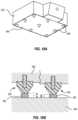
- FIG. 18 Aillustrates one embodiment of a vibration absorption mechanism
- FIG. 18 Billustrates a cross-sectional view of the vibration absorption mechanisms illustrated in FIG. 18 A ;
- FIG. 19 Aillustrates a cross-sectional view of one embodiment of a vibration absorption mechanism
- FIG. 19 Billustrates the vibration absorption mechanism illustrated in FIG. 19 A , but undergoing deformation due to vibrations.
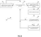
- FIG. 20illustrates a flowchart showing a method of reducing noise and vibration of a smoke evacuation system.
- the present disclosurerelates to smoke evacuation systems. More specifically, the present disclosure relates to methods and apparatuses for managing noise and vibrations of smoke evacuation systems. Noise and vibrations produced by smoke evacuation systems can be distracting and irritating to practitioners performing surgery. The present disclosure relates to methods and apparatuses for reducing noise and vibrations associated with smoke evacuation systems.
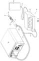
- FIG. 1illustrates an exemplary electrosurgical system 100 .
- the illustrated embodimentincludes a signal generator 102 , an electrosurgical instrument 104 , a return electrode 106 , and a smoke evacuation system 120 .
- Generator 102in one embodiment, is an RF wave generator that produces RF electrical energy.
- Connected to electrosurgical instrument 104is a utility conduit 108 .
- utility conduit 108includes a cable 110 that communicates electrical energy from generator 102 to electrosurgical instrument 104 .
- the illustrated utility conduit 108also includes a vacuum hose 112 that conveys captured/collected smoke and/or fluid away from a surgical site.
- electrosurgical instrument 104includes a hand piece or pencil 114 and an electrode tip 116 .
- Electrosurgical instrument 104communicates electrical energy to a target tissue of a patient to cut the tissue and/or cauterize blood vessels within and/or near the target tissue.
- an electrical dischargeis delivered from electrode tip 116 to the patient in order to cause heating of cellular matter of the patient that is in close contact with or adjacent to electrode tip 116 .
- the tissue heatingtakes place at an appropriately high temperature to allow electrosurgical instrument 104 to be used to perform electrosurgery.
- Return electrode 106is connected to generator 102 by a cable 118 , and is either applied to or placed in close proximity to the patient (depending on the type of return electrode used), in order to complete the circuit and provide a return electrical path to wave generator 102 for energy that passes into the patient's body.
- the electrosurgical instrument 104may comprise a smoke evacuation conduit opening 122 near the electrode tip 116 so as to be able to capture the smoke that is released during a procedure. Vacuum suction may draw the smoke into the conduit opening 122 , through the electrosurgical instrument 104 , and into the vacuum hose 112 toward the smoke evacuation system 120 .
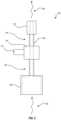
- FIG. 2illustrates a schematic of an embodiment of a smoke evacuation system 400 .
- the smoke evacuation system 400may include a filter 406 and an airflow path 408 .
- the airflow path 408may comprise a pump 410 disposed in-line with the airflow path 408 producing a pressure difference within the airflow path 408 by mechanical action. This pressure difference may cause movement of a gas through the airflow path 408 .
- the airflow path 408may be at least partially comprised of a tube or other conduit that substantially contains and/or isolates the air moving through the airflow path 408 from air outside the airflow path.
- the first zone 416 of the airflow path 408may comprise a tube through which the airflow path 408 extends between the filter 406 and the pump 410 .
- the second zone 418 of the airflow path 408may also comprise a tube through which the airflow path 408 extends between the pump 410 and the exhaust mechanism 414 .
- the airflow path 408also extends through the filter 406 , pump 410 , and exhaust mechanism 414 so that a continuous airflow path 408 extends through the smoke evacuation system 400 .
- the gas drawn through the airflow path 408may be smoke 402 , or the filtered air remaining after the smoke 402 has passed through the filter 406 .
- a motor 412drives the pump 410 .
- the smoke evacuation system 400may also include an exhaust mechanism 414 that may also be disposed in-line with the airflow path 408 .
- the airflow path 408may extend from the inlet port 245 to the outlet port 250 and pass through the filter 406 , pump 410 and exhaust mechanism 414
- the pump 410may cause a suction of smoke 402 that has travelled through the vacuum tube 112 illustrated in FIG. 1 to the filter illustrated in FIG. 2 .
- the smoke 402may be drawn to the filter 406 via a suction created by the pump 410 as discussed above.
- the pump 410may create a pressure difference between a first zone 416 and a second zone 418 of the airflow path 408 . This pressure difference causes the smoke 402 to travel into the filter 406 , which is disposed at an inlet of the airflow path 408 , through the airflow path 408 , and out the exhaust mechanism 414 , which is disposed at an outlet of the airflow path 408 .
- the filter 406may extract potentially harmful, foul, or otherwise unwanted particulates from the smoke 402 .
- the pump 410may be disposed in-line with the airflow path 408 , meaning the gas flowing through the system enters the pump 410 at one end and exits the pump 410 at the other end.
- the pump 410may provide a sealed positive displacement airflow path.
- the pump 410may produce the sealed positive displacement airflow path by trapping (sealing) a first volume of gas and decreasing that volume to a second smaller volume as the gas moves through the pump 410 . Decreasing the volume of the trapped gas increases the pressure of the gas.
- the second pressurized volume of gasmay then be released from the pump at a pump outlet.
- the pumpreleases the pressurized outlet gas into the airflow path 408 and on towards the exhaust mechanism 414 . More details regarding various embodiments of pumps that may provide a sealed positive displacement airflow path are described herein.
- the pump 410may have more than one operating pressure.
- the pump 410may operate at various operating pressures while maintaining a similar flow rate through the airflow path 408 .
- the pump 410may operate at a first operating pressure resulting in a first flow rate of gas through the airflow path 408 .
- the pump 410may also operate at a second operating pressure resulting in a second flow rate.
- the first and second flow rates of gas through the airflow path 408may be the same or substantially similar regardless of the difference in the first and second operating pressures of the pump 410 .
- the pump 410may operate at that higher pressure while still maintaining a constant flow rate of air/gas through the airflow path 408 .
- pumpand “sealed positive displacement pump” as used herein may refer to mechanisms that may transfer or cause movement of a gas by mechanical action and substantially increase the pressure of that gas as the gas is moved.
- a pumpmay refer to any number of different blowers or compressors.
- Fansare not considered “pumps” for purposes of this disclosure. Fans may only operate at a pressure ratio of about 1:1. This pressure ratio does not provide a substantial increase in pressure of the gas being moved.
- a fanmay include rotating blades that create a current or flow of gas from one side of the fan to the other.
- Fanstypically operate at a pressure ratio of about 1:1 and move a relatively high volume of air.
- Typical fans used in smoke evacuation systemsmay have an operational pressure between atmospheric pressure to about 1.5 psig.
- the volumetric airflow capacity of a fandecreases dramatically when blockages increase a pressure resistance inside the airflow path 408 , as shown in FIG. 3 .
- a sealed positive displacement pump, as described above,is affected less by such blockages and performs well against high resistance pressures, as seen in FIG. 3 .
- Fansmay create suction that draws air through the smoke evacuation system, but they are typically very noisy. The noise can be distracting to practitioners performing surgery. Fans used in typical systems can create sufficient suction but struggle to maintain consistent suction when resistance pressures increase in the system due to airflow obstructions or clogging. Fans are prone to create weak and inconsistent airflow rates through the system.
- Blowersdiffer from fans in that they operate at a higher pressure ratio (e.g., between about 1:1 to 1:2).
- a bloweris a high-speed and/or high-volume fan.
- a blowermay be a centrifugal fan that uses rotating impellers to increase the speed and volume of a gas passing through it. Blowers typically have an operational pressure between 1.5 and 1.72 psig and transfer a very high volume of gas relative to fans and compressors.
- Compressorsare pumps that move relatively low volumes of gas with much higher pressure ratios than fans and blowers.
- a typical pressure ratio for a compressorsuch as those described in various embodiments herein, may be greater than about 2:1.
- Compressorsmay operate at a pressure of greater than about 2.72 psig.
- the various compressors described herein, particularly embodiments that include positive displacement compressors,may be advantageous for a number of reasons.
- Positive displacement pumpsmay be much quieter than typical fans used in smoke evacuation systems.
- Positive displacement pumpsalso operate well against resistance pressures due to blockages in the airflow path 408 of the smoke evacuation system 400 .
- Blockagesmay include unwanted particulate build-up or other clogging due to objects from the ambient air being sucked into the airflow path 408 .
- FIG. 3illustrates the relationship between pressure resistance and airflow for a positive displacement pump vs. a typical fan.
- a sealed positive displacement pumpmay maintain a relatively steady airflow regardless of the pressure resistance in the system due to clogging.
- the airflow capability of a fandecreases dramatically as the pressure resistance rises.
- sealed positive displacement pumpssuch as the various embodiments described herein, may still create a suction through the smoke evacuation system 400 even when the system clogs or becomes blocked. This is typically not the case if a fan is used.
- FIG. 4is a table showing the pressure increase, operational pressure, pressure ratio, and air volume transferred by a fan, blower, and compressor for comparison. As shown, compressors are able to produce a pressure ratio of greater than 2:1 between a low-pressure gas entering the pump 410 from a first zone 416 of the airflow path 408 and a pressurized gas exiting the pump 410 into a second zone 418 of the airflow path 408 .
- FIG. 4also shows the relative air volume moved by the fans, blowers, and compressors. Compressors move the lowest volume of air relative to fans and blowers, and fans move the highest volume of air when air flow path conditions are equivalent. FIG. 4 also shows that compressors operate at a pressure ratio of greater than 2:1, as opposed to fans and blowers that operate at pressure ratios closer to 1:1. This means that air/gas exiting a compressor is typically pressurized at twice the pressure of the air/gas entering the compressor at a compressor inlet.
- the various embodiments of the smoke evacuation systemmay include one or more various types of pumps.
- the various pumpsmay be incorporated into the system in order to reduce noise and vibrations, which can be irritating to users and damaging to the system.
- typical fans used in current systemsmay be very noisy and cause significant vibrations. These vibrations can cause the system to travel along a surface where it is placed, thus requiring a secure connection to that surface. This secure connection diminishes the portability of the system and increases the difficulty of installation. Vibrations can also be damaging to internal components of the system, which may not be designed to withstand such vibrations.
- the following descriptionincludes various embodiments of a smoke evacuation system, including various types of pumps, vibration absorption mechanisms, and motor control methods aimed at reducing the noise and vibration of the system in order to solve these problems.
- the pump 410 shown in FIG. 2may be a blower 420 , as illustrated in FIGS. 5 A- 5 B .
- FIG. 5 Aillustrates an exploded view of blower 420 .
- the blower 420may be a hybrid regenerative blower with impeller features that compress the gas 402 passing there through.
- the blower 420may include a top cover 422 , a bottom cover 424 , and an impeller assembly 426 .
- the top cover 422 and the bottom cover 424cooperate to form an outer shell fo the pump 410 /blower 420 .
- a rotary shaft 428may be secured to the center of the impeller assembly 426 and cause the impeller assembly 426 to rotate.
- a motor 412 that may engage the rotary shaft 428is not illustrated in FIG. 5 A , but is shown in FIG. 2 .
- the top cover 422may be secured to the bottom cover 424 to create a sealed circulation path 430 having an inlet 432 and an outlet 434 .
- the circulation path 430may also be referred to as an airflow path 430 of the blower.
- the impeller assembly 426may be disposed between the top cover 422 and bottom cover 424 so that the impeller blades 436 reside within the sealed circulation path 430 .
- a motordrives the impeller assembly 426 to rotate about the rotary shaft 428 so that the impeller blades 436 travel in a circular path through the sealed circulation path 430 . This circular motion of the impeller blades 436 creates a suction so that a gas 402 is drawn into the inlet 432 , travels around the sealed circulation path 430 , and exits the blower 420 out of the outlet 434 .
- FIG. 5 Billustrates the flow path 438 of a gas 402 flowing through the sealed circulation path 430 of the blower 420 .
- FIG. 5 Billustrates a cross-sectional view of the blower 420 showing impeller assembly 426 inside sealed circulation path 430 .
- the impeller assembly 426is driven clockwise in this embodiment.
- centrifugal forcemoves gas molecules from the blade root 440 to its tip 442 .
- the gas moleculesthen leave the blade tip 442 and enter the portion of the sealed circulation path 430 not occupied by the impeller blades 436 .
- the gas moleculesare then drawn back down a succeeding impeller blade 436 in repeated fashion.
- This repeated flow path 438 of the gasprovides a quasi-staging effect that may increase a pressure differential capability of the blower 420 .
- This type of regenerative blower 420passes the gas through many compression cycles as the gas molecules pass up and down various impeller blades 436 with each revolution of the impeller assembly 426 .
- a gas exiting the outlet 434may have a higher pressure than the gas entering at the inlet 432 .
- the speed of the rotating impeller assembly 426is proportional to the pressure differential of the gas. For example, a higher rotational speed of the impeller assembly 426 increases the pressure differential between the gas at the inlet 432 compared to the gas exiting at the outlet 434 . A lower rotational speed results in a lower pressure differential.
- the number of impeller blades 436may be odd so as to limit resonance, which can create noise and vibrations.
- An odd number of blades 436reduces the chance of elastic frequencies from the blades 436 becoming tuned to a resonant frequency of the rotary shaft 428 .
- Natural frequencies of the top and bottom covers 422 , 424are also offset from the frequencies of the blades 436 and rotary shaft 428 to limit noise and vibrations of the blower 420 due to the harmonics of the blower 420 .
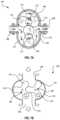
- the pump 410 shown in FIG. 2may be a claw pump 444 .
- Various cross-sectional views of the claw pump 444are illustrated in FIGS. 6 A- 6 C .
- the claw pump 444may be a cooperative dual drive shaft claw pump.
- FIGS. 6 A- 6 Cillustrate a top cross-sectional view of the claw pump 444 in three different stages of rotation.
- the claw pump 444is a positive displacement pump that compresses gas by decreasing the volume of an initial volume of gas that enters the pump.
- the claw pump 444may have first and second counter-rotating rotary elements, or claws 446 , 448 disposed within a single circulation path of the pump 444 .
- the first claw 446may rotate clockwise and the second claw 448 may rotate counter-clockwise, as indicated by the arrows in FIG. 6 B .
- FIG. 6 Ashows an initial state of the claw pump 444 where a gas 450 resides in a sealed space between the claws 446 , 448 and the pump housing 452 .
- the gas 450is illustrated in gray.
- FIG. 6 Cillustrates the gas 450 in a compressed state, where the volume of the sealed space in which the gas 450 resides has been reduced due to the rotation of the claws 446 , 448 .
- the inlet and outlet ports of the claw pump 444are not shown in detail because of the top cross-sectional view of FIGS. 6 A- 6 C .
- An inlet 456may, for example, be disposed below the claw pump 450 an outlet 454 may be disposed above the claw pump 444 so that the compressed volume of gas 450 shown in FIG. 6 C may enter and exit via the inlet 456 and outlet 454 perpendicular to the viewing plane.
- the inlet 456 and outlet 454may be configured so that the inlet 456 is disposed below the viewing plane and the outlet 454 is disposed above the viewing plane, or vice versa, so that the gas travels through the claw pump 444 perpendicular to the viewing plane.
- Embodiments of the smoke evacuation system 400may include a cooperative dual drive shaft claw pump 444 such as the one illustrated in FIGS. 6 A-C may enjoy reduced noise and vibrations. Pumps with single shaft rotary elements may suffer from vibrations due to slight imbalances of components that rotate around a central drive shaft. In the cooperative dual drive shaft claw pump 444 illustrated, the two rotating claws 446 , 448 rotate in opposite directions and may balance each other out. This balance may minimize vibrations.
- the pump 410 of the smoke evacuation system 400may also be a lobe compressor 458 .
- FIG. 7 Aillustrates a cross-sectional view of a lobe compressor 458 including two counter-rotating rotary elements 460 , 462 .
- Each rotary element 460 , 462may have two or more lobes 478 .
- the lobe compressor 700functions similarly to the claw pump 444 described herein, in that the two rotary elements 460 , 462 rotate in opposite directions, as indicated by the arrows marked on the two rotary shafts 470 , 472 , in order to create a sealed positive displacement airflow path through the compressor 458 .
- the rotation of the rotary elements 460 , 462draws in a low-pressure gas 474 through an inlet 466 and moves the gas 474 through the compressor 458 to an outlet 468 .
- the volume of the gas 474decreases, which pressurizes the gas.
- the pressurized gas 476then exits the compressor 458 via the outlet 468 .
- FIG. 7 Billustrates a lobe compressor 480 that comprises two rotary elements 460 , 462 having three lobes 478 each.
- a low-pressure gasis drawn into the inlet 466 , driven through the compressor 480 via the rotating lobes 478 , after which the volume of the inlet gas is reduced and pressurized before it exits out the outlet 468 of the compressor 480 .
- FIG. 7 Cillustrates yet another embodiment of a lobe compressor 482 that operates similar to the other lobe compressors described herein.
- the lobe compressor 482 illustrated in FIG. 7 Cincludes two rotary elements 460 , 462 that have five lobes each.
- Other embodimentsmay include lobe compressors with rotary elements that have four lobes, or more than five lobes.
- a smoke evacuation system 400may include multiple rotary elements that cooperatively counter-rotate to produce a sealed circulation path that traps and compresses gas by positive displacement action.
- These other pumpsmay include, but are not limited to, two stage rotary vane pumps and dual screw eccentric pumps.
- the various counter rotating dual drive shaft pumps with multiple rotary elements described hereinmay provide a pressure differential of at least 1.5 psig between a low-pressure inlet gas entering the pump 410 from a first zone 416 of the airflow path 408 and a high-pressure outlet gas exiting the pump 410 into a second zone 418 of the airflow path 408 .
- Other embodimentsmay include similar pumps that produce a pressure differential of between 1 and 2 psig.
- Yet other embodimentsmay produce a pressure differential of greater than 2 psig.
- the various counter rotating dual drive shaft pumps with multiple rotary elementsmay also reduce vibration and noise within the smoke evacuation system 400 for the same reasons as discussed above in reference to the claw pump 444 .
- the two rotary elementsrotate in opposite directions and balance each other out. This balance may cancel out vibrations and resulting noise.
- the pump 410may be a scroll compressor.
- Scroll compressorsare positive displacement compressors.
- the various embodiments of a scroll compressor described hereinmay achieve all the advantages of the pumps described above, including but not limited to the same compression ratios, operating pressures, vibration reduction, and noise reduction of the smoke evacuation system 400 .
- FIG. 8illustrates a cross-sectional view of a scroll compressor 800 .
- the scroll compressormay include a stator scroll 484 and a moving scroll 486 .
- the stator scroll 484is fixed in position while the moving scroll 486 orbits eccentrically without rotating.
- the moving scroll 486may orbit eccentrically such that the moving scroll 486 does not rotate about its own central longitudinal axis, but the central longitudinal axis of the moving scroll 486 would orbit about a central longitudinal axis of the stator scroll 484 .
- the central longitudinal axes of the stator and moving scrolls 484 , 486extend perpendicular to the viewing plane of the scrolls 484 , 486 .
- the stator scroll 484 and the moving scroll 486may be interleaved with each other to form discreet sealed compression chambers 488 .
- FIG. 9illustrates a perspective view of two scroll compressors 494 , 496 disposed in series. Only the moving scrolls 498 , 500 are shown for illustrative purposes.
- the first moving scroll 498may be oriented at 180-degrees from the second moving scroll 500 .
- the first moving scroll 498 of the first scroll pump 494may orbit in an opposite direction of the second moving scroll 500 of the second scroll pump 496 .
- the first moving scroll 498may orbit counterclockwise and the second moving scroll 500 may orbit clockwise.
- Other embodimentsmay include first and second scroll pumps 494 , 496 that are oriented opposite of the scrolls illustrated.
- the two scroll pumps 494 , 496may be disposed in series within a sealed airflow path 408 .
- compressed gas exiting the first scroll pump 494 at an outlet of the first scroll pump 494may enter an inlet of the second scroll pump 496 to be further compressed.
- a single scroll pumpsuch as those described above, orbits eccentrically and therefore inherently shifts its weight around while orbiting to produce vibrations.
- the opposite orbiting movement of the two scrolls 498 , 500 in series, illustrated in FIG. 9may counterbalance one another in order to limit vibrations in the system 400 .
- the pump 410may comprise two scroll pumps of different sizes.
- FIG. 10 Aillustrates a perspective view of first and second scroll pumps 502 , 504 .
- stator scrolls of the scroll pumps 502 , 504are not shown. Rather, only the moving scrolls 502 , 504 are shown for illustrative purposes.
- the first scroll 502may be a low flow-capacity scroll that orbits at a relatively low revolutions-per-minute (“RPM”) compared to the other pumps described herein.
- the second scroll 504may be a high flow-capacity scroll that also orbits at a relatively low RPM.
- the high flow scroll 504may have a higher flow-capacity than the low flow-capacity scroll 502 even when the two are orbiting at the same RPM due to a larger diameter 506 compared to a diameter of the low flow-capacity scroll 502 .
- the low-flow scroll 502 and the high flow scroll 504may be disposed in series, as described previously in reference to the dual in-line scroll pump illustrated in FIG. 9 .
- the two scrolls 502 , 504may also be disposed next to each other as illustrated in FIG. 10 A .
- Arrows 508 and 510indicate the orbiting direction of the low flow and high flow scrolls 502 , 504 , respectively.
- FIG. 10 Aillustrates both scrolls orbiting in a counter-clockwise direction.
- Other embodimentsmay include scrolls that orbit clockwise.
- Yet other embodimentsmay include scrolls that orbit in opposite directions to one another.
- Pairing a low flow scroll 502 with a high flow scroll 504 as described abovehas a number of advantages.
- the configuration illustrated in FIG. 10 Amay allow for variable selectable flow rates without increasing the RPM of the scrolls.
- the low flow scroll 502may produce a constant low-level airflow 512 over time.
- the high flow scroll 504may provide higher flows over time.
- the high flow scroll 504may be selectively turned on and off to provide discrete higher flows 514 when needed. Such a need may arise, for example, to overcome a temporarily increased pressure resistance (e.g., due to clogging) within the airflow path 408 of the smoke evacuation system 400 .
- variable flow ratescan be accomplished while maintaining a low RPM of the orbiting scrolls. Maintaining low RPMs of the scrolls may decrease vibrations and noise of the pump 410 .
- Vibrationscan damage components of the system or shorten their useful lifespan. Vibrations can even cause components of the system to move across the surfaces on which they rest, requiring that they be fixed to the surface. This decreases the portability of the system and increases the difficulty of installation. Vibration absorption mechanisms may be incorporated into the smoke evacuation system 400 to further limit vibrations. These absorption mechanisms can be used in conjunction with the various pumps described herein, or they may be incorporated separately into various other embodiments of the system 400 .
- the first zone 416 of the airflow path 408may be an inlet to the pump 410 that may pass through the inner housing 518 .
- the second zone 418 of the airflow path 408may be an outlet from the pump that may pass through the inner housing 518 as well.
- Other embodiments of a smoke evacuation systemmay include an inner housing 518 that houses all or none of the first and second zones 416 , 418 of the airflow path 408 .
- FIG. 11illustrates a cross-sectional view of smoke evacuation system 516 in order to show the configurations of the inner and outer housings 518 , 520 .
- the inner housing 518may completely encapsulate various components of the system 516 , such as the pump 410 and the motor 412 (including an outer shell 413 thereof), thus totally isolating them from other components of the system 516 , such as the filter 406 and exhaust mechanism 414 .
- the inner housing 518may only partially surround or encapsulate these or other components.
- the outer housing 520may house other components of the smoke evacuation system 516 that are not housed within the inner housing 518 .
- the embodiment illustrated in FIG. 11shows outer housing 520 that houses the filter 406 , exhaust mechanism 414 , and portions of the first and second zones 416 , 418 of the airflow path 408 .
- the outer housing 520may also house the entire system, including the inner housing 518 and components therein.
- FIG. 11illustrates a cross-sectional view of a smoke evacuation system 516 in order to show the configurations of the inner and outer housings 518 , 520 .
- the outer housing 520may completely encapsulate various components of the system 516 , such as the filter 406 and the exhaust mechanism 414 , thus totally isolating them from an exterior environment surrounding the system 516 .
- the outer housing 520may also encapsulate the inner housing 518 .
- the outer housing 520may completely encapsulate components of the smoke evacuation system 516 not encapsulated by the inner housing 518 , such as the filter 406 and exhaust mechanism 414 .
- the outer housing 520may only partially surround or encapsulate these or other components.
- Vibration absorption mechanismsmay be disposed, and serve as interfaces, between the inner and outer housings 518 , 520 .
- FIG. 12illustrates an inner housing 518 interfacing with an outer housing 520 via various vibration absorption mechanisms 522 . Only a portion of the outer housing 520 is shown for illustrative purposes.
- Various components of a smoke evacuation system 400are also shown, including first and second zones 416 , 418 of the airflow path 408 , which may serve as an inlet and outlet of the pump disposed within inner housing 518 .
- the filter 406illustrated in FIG. 11
- motor 412and first and second zones 416 , 418 of the airflow path 408 may be disposed within the outer housing 520 but outside the inner housing 518 .
- the pump 410may be enclosed inside the inner housing 518 and therefore not shown in FIG. 12 .
- vibration absorption mechanisms 522may comprise springs disposed between inner and outer housings 518 , 520 .
- the pump and/or motor enclosed/housed within the inner housing 518may create vibrations that result in unwanted movement or noise of the system.
- the vibration absorption mechanisms 522may absorb these vibrations so that a substantial portion of the vibrations are not transferred to the outer housing 520 .
- the springs 522 illustrated in FIG. 12may compress, stretch, or laterally flex due to vertical or horizontal vibrational forces acting on the springs 522 . These forces may be a result of the inner housing 518 vibrating up and down, or laterally. These movements caused by the vibrating motor and/or pump within the inner housing 518 may be transferred into the springs 522 . As the springs 522 compress, stretch, or laterally flex, the spring may absorb a substantial portion of the vibrations. Thus, the vibrations may not be substantially transferred from the inner housing 518 to the outer housing 520 .
- FIG. 12illustrates an embodiment wherein four vibration absorption mechanisms 522 are disposed between the inner housing 518 and the outer housing 520 .
- Other embodimentsmay include more or less than four vibration absorption mechanisms 522 disposed between the inner housing 518 and the outer housing 520 .
- the location of the vibration absorption mechanisms 522may also vary in other embodiments.
- a vibration absorption mechanism 522may be disposed at the bottom center of the inner housing 518 , rather than just at the bottom four corners of the inner housing 518 as illustrated.
- a number of plates 524may be secured to or integrally formed with the inner housing 518 and the vibration absorption mechanisms 522 may be secured directly or indirectly to the plates 524 .
- Other embodimentsmay or may not include plates 524 .
- other embodimentsmay have vibration absorption mechanisms 522 that are secured directly to the inner housing 518 .
- Other embodimentsmay include more or less than two plates 524 secured to both the inner housing 518 and vibration absorption mechanism 522 as illustrated in FIG. 12 .
- FIG. 13 Ashows an inner housing 518 secured to an outer housing 520 via plates 524 and vibration absorption mechanisms 526 .
- the vibration absorption mechanisms 526 of the embodiment illustrated in FIG. 13 Amay be ring isolators 526 . Similar to the springs 522 disposed between the plates 524 and outer housing 520 illustrated in FIG. 12 , the ring isolators 526 may absorb vibrations from the pump 410 and/or motor 412 housed within the inner housing 518 so that a substantial portion of those vibrations are not transferred to the outer housing 520 .
- FIG. 13 Billustrates how the ring isolators 526 may be secured to the housings 518 , 520 and/or plates 524 .
- the ring isolators 526may be configured in a circular ring shape and be disposed between the plate 524 and outer housing 520 so that the ring isolator 526 acts as a barrier between the two, as illustrated in FIGS. 13 B and 13 C .
- Two or more securing mechanisms 528may secure the plate 524 and outer housing 520 to the ring isolator 526 on opposing sides of the ring isolator 526 as shown.
- the securing mechanisms 528 illustrated in FIGS. 13 B and 13 Ccomprise a nut and bolt assembly.
- Other embodimentsmay include other securing mechanisms 528 .
- other embodimentsmay include securing mechanisms 528 that comprise nails, screws, adhesives, clips, hooks, and the like.
- FIG. 13 Cillustrates how a ring isolator 526 may absorb vibrations.
- the ring isolatormay be comprised of a flexible material such as an elastomer.
- a flexible materialsuch as an elastomer.
- one embodiment of the ring isolator 526may be made of silicone.
- Other embodimentsmay include ring isolators 526 that comprise other elastomeric materials, such as rubber.
- the ring isolator 526may flex when acted upon by a force, such as the forces created by vibrations 530 .
- FIG. 13 Cillustrates vibrations 530 pushing down on the plate 524 .
- Vibrations 530may be oscillatory movements that create forces that may push downward, pull upward, or pull sideways on the plate 524 .
- the ring isolator 526may absorb all of these potential movements of the plate 524 by deforming and/or flexing in all different directions.
- the ring isolator 526may expand and stretch taller, or shift side to side in response to various vibrational forces. In this way, ring isolators 526 may absorb the vibrations 530 of the inner housing 518 so the vibrations 530 are not substantially transferred to the outer housing 520 .
- FIG. 14 Aillustrates an embodiment where the vibration absorption mechanism comprises an elastomeric sheet 532 .
- the elastomeric sheet 532may be disposed between the plates 524 and outer housing 520 similar to the springs 522 and ring isolators 526 described herein.
- the elastomeric sheet 532may be a single sheet covering an entire area between the first housing 518 and the second housing 520 as shown in FIG. 14 A .
- Other embodimentsmay include multiple sheets 532 .
- the sheet 532may comprise four separate sections disposed at the four bottom corners of the inner housing 518 and/or plates 524 , similar to where the ring isolators 526 are disposed according the embodiment illustrated in FIG. 13 A .
- Other embodimentsmay include two separate sheets 532 , each connecting two corners of the inner housing 518 and/or plates 524 to the outer housing 520 .
- FIG. 14 Bshows one way in which the elastomeric sheet 532 may be secured between the plate 524 and the outer housing 520 .
- two nuts molded into the sheet 532provide a fixture through which two screws/bolts may be threaded from above the plate 524 and below the outer housing 520 .
- Other embodimentsmay include other securing mechanisms, such as nails, hooks, adhesives, and so forth.
- the sheet 532may absorb vibrations from the inner housing 518 due to the pump 410 or motor 412 and substantially prevent those vibrations from being transferred to the outer housing 520 .
- FIG. 15shows a tube configuration that may enhance the vibration absorption capabilities of various tubes. More specifically, FIG. 15 shows bent tubes 536 , 537 that may absorb vibrations due to their bent configuration.
- the tubes 536 , 537may be inlet and/or outlet tubes to the pump 410 residing within the inner housing 518 .
- the motor 412may be disposed outside the inner housing 518 and engage the pump 410 through the housing 518 .
- the motor 412 and/or pump 412may create vibrations in the system that may travel into the inner housing 518 and through the tubes 536 , 537 .
- the tubes 536 , 537may include a U-shaped portion 538 at one or more locations along the length of the tubes 536 , 537 .
- the U-shaped portions 538 of the tubes 536 , 537may allow the tubes 536 , 537 to flex in response to vibrations to a greater degree than straight tubes having no U-shaped portions 538 .
- the U-shaped portions 538 of the tubes 537also may increase the total length of the tubes 536 , 537 to increase the amount of tube material available to absorb and dampen vibrations.
- each tube 536 , 537has one U-shaped portion 538 .
- Other embodimentsmay include more than one U-shaped portion 538 .
- Some embodimentsmay include tubes 536 , 537 bent into other shapes, such as S-shaped portions or the like.
- the U-shaped portions 538 of the tubes 536 , 537may be made of material that is the same or similar to the rest of the tubes 536 , 537 . Some embodiments may include U-shaped portions 538 that are made of a different material than the rest of the tubes 536 , 537 . For example, some embodiments may include U-shaped portions 538 that are made of an elastomeric material. A U-shaped portion 538 made of an elastomeric material, for example rubber, may absorb vibrations to a greater degree than more rigid materials such as plastics and the like.
- FIGS. 16 A through 16 CThree different configurations of tubes 540 configured to absorb vibrations are illustrated in FIGS. 16 A through 16 C .
- FIG. 16 Aillustrates a tube 540 having a flexible portion 542 .
- the flexible portion 542may be made of an elastomeric material such as silicone, rubber, or the like.
- FIG. 16 Billustrates a tube 540 that includes a U-shaped portion 544 similar to those U-shaped portions 538 illustrated in FIG. 15 .
- the U-shaped portion 544may be made of material similar to the rest of the tube 540 or it may be made of elastomeric material such as silicone, rubber, or the like.
- FIG. 16 Cillustrates a tube 540 that includes 90-degree bent portions 546 , in order to accomplish the same vibration absorption capacity of the tubes 540 described above.
- the bent portions 546may be made of material similar to the rest of the tube 540 or may be made of elastomeric material such as silicone, rubber, or the like.
- additional absorption mechanismsmay be disposed on an outside surface of the outer housing 520 .
- the smoke evacuation system 400may be placed on a support surface, such as a table or countertop when in use. Vibration of the outer housing, due to the operation of internal components of the system 400 such as the motor 412 and/or pump 410 , may cause the entire system 400 to bounce/travel along the support surface.
- Additional vibration absorption mechanismsmay be disposed on a bottom outside surface of the outer housing 520 to act as an interface between the smoke evacuation system 400 and the support surface on which the outer housing 520 is placed in order to reduce this effect.
- the vibration absorption mechanismsmay act to absorb the vibrations so the vibrations are not substantially transferred to the support surface.
- the vibrations absorption mechanismsmay also provide greater friction between the outer housing 520 and a support surface to reduce travel along the surface due to vibrations.
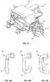
- FIG. 17 Ashows an outer housing 520 that includes a number of feet 548 . These feet 548 are vibration absorption mechanisms. The feet 548 are disposed on a bottom surface 550 of the outer housing 520 and may act as an interface between the outer housing 520 and a support surface on which the outer housing 520 is placed.
- the embodiment illustrated in FIG. 17 Aincludes four feet 548 disposed on the bottom surface 550 .
- Other embodimentsmay include more or less than four feet 548 that may be arranged in any number of configurations. For example, one embodiment may include only three feet 548 .
- Other embodimentsmay include five or more feet 548 with some of the feet 548 disposed near the center of the bottom surface 550 as well as the corners.
- FIG. 17 Billustrates a cross-sectional view of one of the feet 548 illustrated in FIG. 17 A .
- the foot 548may be comprised of a flexible matrix 554 secured to the bottom surface 550 via a rigid or semi-rigid bolt 552 .
- the bolt 552may be threaded or otherwise secured to the bottom surface 550 .
- the bolt 552may protrude beyond the bottom surface 550 and the flexible matrix 554 may be molded around the protrusion of the bolt 552 .
- the flexible matrix 554 of the foot 548may have a first diameter D 1 and a second diameter D 2 .
- the first diameter D 1 and the second diameter D 2may vary in size.
- the first diameter D 1may be smaller than the second diameter D 2 .
- a contact pressure between the foot 548 and a support surfacemay increase as the diameter of the foot 548 decreases.
- certain diametersmay absorb a given range of vibrational frequencies better than others. It may therefore be advantageous to vary the diameter of the foot 548 as shown in FIG. 17 B .
- D 1may absorb a first frequency of vibrations, or first range of frequencies
- D 2may absorb a second frequency of vibrations, or second range of frequencies. Therefore, having a foot 548 , such as the foot 548 illustrated in FIG. 17 C , with various diameters D 1 .
- D 2may enable the foot 548 to substantially absorb both the first and second frequencies, or ranges thereof.
- feetmay include feet with any number and combination of different diameters to meet the specific range of frequencies being absorbed.
- FIG. 17 Cshows another embodiment of a foot 548 that includes a first diameter D 1 that is smaller than a second diameter D 2 .
- the edge profile 556 of the foot 548is straight so that the foot 548 substantially resembled an inverse cone.
- Other embodimentsmay include edge profiles 556 that result in various other shapes.
- the feet 548may be secured to the bottom surface 550 in a variety of ways.
- the feet 548may be secured via hooks, nails, adhesives, or the like, without the need for a bolt 552 as shown in FIG. 17 B .
- the feet 548including other embodiments of feet described herein, may be made of an elastomeric material, such as rubber, silicone, or the like.
- the elastomeric material of the flexible matrix 554may absorb vibrations from the outer housing 520 and provide added friction between the bottom surface 550 of the outer housing 520 and a support surface on which the outer housing 520 is placed.
- FIG. 18 Aillustrates a number of feet 558 disposed on the bottom surface 560 of an outer housing 520 .
- nine feet 558serve as an interface between the bottom surface 560 and a support surface.
- Increasing the number of feet 558may increase the vibration absorption capacity of the system. It may also increase the friction between the bottom surface 560 of the outer housing 520 and a support surface to minimize vibrational travel.
- Other embodimentsmay include more than nine feet 558 disposed on the bottom surface 560 in order to increase friction and vibration absorption capacity.
- FIG. 18 Billustrates a cross-sectional view of two of the feet 558 shown in FIG. 18 A .
- Flexible spacers 562may be disposed on the feet 558 to compensate for uneven surfaces 560 , 564 so that all the feet 558 may be in contact with the support surface 564 despite unevenness.
- the spacers 562may compress from a first thickness X 1 to a second thickness X 2 .
- the spacers 562may be made of an elastomeric material, such as silicone or rubber, so that the thickness X of the spacer 562 may vary depending on the unevenness of the support surface 564 on which the outer housing 520 is placed. In this way, all of the feet 558 may be in contact with the support surface 564 in order to increase vibration absorption capability and friction between the bottom surface 560 and the support surface 564 .
- the spacers 562may also prevent the outer housing 520 from rocking due to a space or gap between the feet and the support surface.
- FIG. 19 Ashows a cross-sectional view of one embodiment of a foot 566 for absorbing vibrations. This embodiment is similar to the embodiment illustrated in FIG. 17 C , except here the first diameter D 1 is greater than the second diameter D 2 .
- FIG. 19 Billustrates how the foot 566 , which may be comprised of an elastomeric material, may deform due to vibrations in the outer housing 520 . As shown, vibrational movements of the outer housing 520 , illustrated by arrows 576 , are transferred to the foot 566 . The foot 566 may laterally deform, as illustrated by arrows 578 , from a first shape 572 to a second shape 568 .
- This lateral deformation and/or change in shape of the foot 566may occur while the interface 574 between the foot 566 and the support surface remains substantially constant. In this way, the foot 566 may absorb vibrations without substantially transferring them to the support surface 570 or traveling across the support surface 570 .
- vibration absorption mechanisms described hereinincluding vibration absorption mechanisms disposed between inner and outer housings, flexible tubing, U-shaped tubing, and feet disposed on a bottom surface of the outer housing, may be employed singly or together in a multitude of combinations. These embodiments may also be included within various embodiments of a smoke evacuation system that includes various types of pumps, blowers, and/or compressors.
- the vibration absorption mechanisms described herein, combined with pumps that reduce vibrations and noise,may provide a substantial decrease in vibrations and noise inherent in typical smoke evacuation systems.
- the smoke evacuation system 400 illustrated in FIG. 2includes motor 412 engaging the pump 410 .
- the motormay rotate a rotary shaft of the various pumps 410 described herein.
- the motor 412may be a permanent magnet synchronous motor.
- Other embodimentsmay include a brushless DC motor. Brushless motors may have large starting torques from a fully stopped condition for use with the various pumps described herein. Brushless motors may also have less noise, greater dynamic response, and better speed-vs.-torque characteristics than brushed motors.
- the pump 410may create a pressure differential between a gas entering the pump 410 and a gas exiting the pump 410 , as described above. This pressure differential, or compression ratio of the pump 410 may result in a high starting torque of the motor 412 in order to initiate the motor 412 rotating the pump 410 .
- Motor control methodsmay be employed to reduce the vibrations and increase motor efficiency and lifespan. Unwanted debris from the outside environment may inadvertently enter the airflow path 408 and cause clogging and/or blockages. These blockages within the system can cause pump and airflow path resistance pressures to rise as airflow is impeded. In order to maintain necessary airflow while blockages are present, pumps and/or motors may need more power and/or speed in order to compensate. Increased speed and/or power may diminish the efficiency of the motor and pump as well as decrease their lifespan.
- Various control methods of a smoke evacuation systemparticularly methods of motor regulation, as described herein, may maintain airflow rates, increase motor efficiency, and preserve the lifespan of the motor and/or pump, especially when blockages and/or clogging of the system occurs.
- a method 580 for regulating the motor to reduce noise and vibration in a smoke evacuation systemis shown in FIG. 20 .
- the systemmay sense or detect whether smoke is present to be evacuated or not. This detection may be done automatically when the practitioner begins cutting a patient during electrosurgery, or a separate smoke sensor may be employed to detect smoke present at cutting site. If smoke is present to be evacuated, then a next step 582 of the method may be to regulate the motor so that the rotational speed of the motor results in full smoke evacuation. If no smoke is present to be evacuated, then the next step may be to regulate the motor to operate at a rotational speed so that the motor is in sleep mode 584 .
- a method of regulating the motormay include varying a supply of electrical current to the motor.
- the method 580may include supplying a first amount of current to the motor to cause the motor to operate at a first performance level.
- a second amount of currentmay be supplied to the motor to cause the motor to operate at a second performance level.
- the supply of currentmay be accomplished by varying a pulse width modulation (PWM) duty cycle of an electrical input to the motor.
- the currentmay be varied by adjusting the frequency of the current supplied to the motor.
- the motormay be engaged with a rotary mechanism, such as the compressors and blowers described above, so that reducing the duty cycle or frequency of a current input to the motor decreases the rotational speed of the rotary mechanism.
- a regulation of the motormay depend on an initial condition, such as the rotational speed of the rotary mechanism. For example, once the system is running, the regulation of the motor may operate the motor at a constant speed that equals the initial rotational speed of the motor.
- the first performance level of the motormay result in a first rotational speed of a rotary shaft of the motor engaging a rotary mechanism. The first performance level therefore, may result in a faster rotation of the rotary mechanism.
- This first performance level, and corresponding rotation speed of the rotary mechanismmay be the speed needed for normal suction of a gas through the airflow path.
- a second performance levelmay be slower than the first so that the second performance level causes the rotary mechanism to operate at a speed lower than the first level.
- the first performance levelmay be employed when there is no smoke produced by the electrosurgical instrument, but it is advantageous to keep the smoke evacuation system active. For example, a practitioner performing electro-surgery may temporarily have no need to suck smoke into the system to be filtered because the practitioner is not currently cutting the flesh of the patient and producing smoke. Instead of completely turning off the smoke evacuation system every time smoke is not being produced, and suction is temporarily not needed, the motor may switch to the second, slower performance level.
- the motorWhen the practitioner begins cutting again with the electrosurgical instrument, producing unwanted smoke, the motor may be switched back to the first, higher performance level, thus creating a higher vacuum pressure necessary to suck smoke into the system to be filtered.
- This lower second performance levelmay be thought of as a sleep mode. In sleep mode, the motor may still run, but not to its full or usual strength/rotational speed. The sleep mode may preserve the lifespan of the motor, and/or rotary mechanism with which it is engaged, by reducing the stress and wear caused by running the motor at full capacity at all times.
- the second, lower performance level of the motormay be more advantageous than turning the motor completely off when suction is not needed, and switching the motor on when suction is needed. This is because a practitioner may need to use the suction only intermittently during long periods of surgery. Turning a motor on from a completely turned-off state requires high start-up torques in order to overcome the standstill inertia of the motor. Repeatedly turning the motor on from a completely off mode in this manner is inefficient and may decrease the lifespan of the motor.
- employing a sleep mode as described above, with a first and second performance levelallows the motor to remain on during intermittent non-use of the system during surgery, so that activation of the first performance level when suction is needed can be done without the higher torques needed to overcome standstill inertia.
- a method of motor controlmay be employed to limit substantial overheating of the motor.
- the motormay overheat if a blockage in the airflow path of the smoke evacuation system causes an overworking of the motor and/or rotary mechanism as they attempt to compensate for the blockage and maintain a constant airflow rate. Therefore, in the method 580 for regulating the motor, a further step may include detecting an operational parameter.
- the operational parametermay be, but is not limited to, the temperature of the motor and/or rotary mechanism and/or the pressure in the airflow path of the smoke evacuation system.
- the next step 590may be to compare the detected operational parameter to an operational parameter limit. This parameter limit may be preset. If the detected operational parameter is greater than or equal to the operational parameter limit, the next step 592 of the method may include altering the operational parameter to be less than the operational parameter limit. In one embodiment, the method may include setting a temperature limit and sensing a temperature of the motor and/or rotary mechanism. When the temperature of the motor and/or the rotary mechanism is equal to or greater than the temperature limit, the motor may be shut off or its performance level reduced.
- the methodmay include defining a pressure limit and sensing a pressure within the circulation path of the rotary mechanism and/or the airflow path of the smoke evacuation system.
- a pressure inside the airflow path or rotary mechanismmay increase when blockage occurs inside the airflow path as described above.
- the motormay be shut off or its performance level reduced, as described above, when the sensed pressure is equal to or greater than the set pressure limit.
- the methodmay include disengaging the motor from the rotary mechanism. The motor may disengage from the rotary mechanism via a clutch.
- the methodmay include manipulating one or more orifices disposed near the motor within the airflow path of the smoke evacuation system.
- This methodmay also include defining a pressure limit and sensing a pressure within the airflow path as described above. When the sensed pressure is equal to or greater than the pressure limit, the one or more orifices may be opened to allow air to flow from inside the otherwise closed airflow path of the system to the surrounding environment, or vice versa. Opening the one or more orifices may reduce the pressure within the system, thus preventing the motor and/or rotary mechanism from attempting to compensate for the higher pressure.
Landscapes
- Engineering & Computer Science (AREA)
- Mechanical Engineering (AREA)
- General Engineering & Computer Science (AREA)
- Health & Medical Sciences (AREA)
- Life Sciences & Earth Sciences (AREA)
- Heart & Thoracic Surgery (AREA)
- Surgery (AREA)
- Public Health (AREA)
- Veterinary Medicine (AREA)
- Biomedical Technology (AREA)
- Animal Behavior & Ethology (AREA)
- General Health & Medical Sciences (AREA)
- Molecular Biology (AREA)
- Physics & Mathematics (AREA)
- Plasma & Fusion (AREA)
- Nuclear Medicine, Radiotherapy & Molecular Imaging (AREA)
- Otolaryngology (AREA)
- Medical Informatics (AREA)
- Anesthesiology (AREA)
- Vascular Medicine (AREA)
- Hematology (AREA)
- Structures Of Non-Positive Displacement Pumps (AREA)
- Applications Or Details Of Rotary Compressors (AREA)
- Jet Pumps And Other Pumps (AREA)
Abstract
Description
Claims (17)
Priority Applications (4)
| Application Number | Priority Date | Filing Date | Title |
|---|---|---|---|
| US15/826,370US11725664B2 (en) | 2017-11-29 | 2017-11-29 | Noise and vibration management for smoke evacuation system |
| PCT/IB2018/059378WO2019106548A1 (en) | 2017-11-29 | 2018-11-28 | Noise and vibration management for smoke evacuation system |
| US18/346,675US12331748B2 (en) | 2017-11-29 | 2023-07-03 | Noise and vibration management for smoke evacuation system |
| US19/202,268US20250264104A1 (en) | 2017-11-29 | 2025-05-08 | Noise and vibration management for smoke evacuation system |
Applications Claiming Priority (1)
| Application Number | Priority Date | Filing Date | Title |
|---|---|---|---|
| US15/826,370US11725664B2 (en) | 2017-11-29 | 2017-11-29 | Noise and vibration management for smoke evacuation system |
Related Child Applications (1)
| Application Number | Title | Priority Date | Filing Date |
|---|---|---|---|
| US18/346,675ContinuationUS12331748B2 (en) | 2017-11-29 | 2023-07-03 | Noise and vibration management for smoke evacuation system |
Publications (2)
| Publication Number | Publication Date |
|---|---|
| US20190162186A1 US20190162186A1 (en) | 2019-05-30 |
| US11725664B2true US11725664B2 (en) | 2023-08-15 |
Family
ID=65003428
Family Applications (3)
| Application Number | Title | Priority Date | Filing Date |
|---|---|---|---|
| US15/826,370Active2039-09-09US11725664B2 (en) | 2017-11-29 | 2017-11-29 | Noise and vibration management for smoke evacuation system |
| US18/346,675Active2037-12-04US12331748B2 (en) | 2017-11-29 | 2023-07-03 | Noise and vibration management for smoke evacuation system |
| US19/202,268PendingUS20250264104A1 (en) | 2017-11-29 | 2025-05-08 | Noise and vibration management for smoke evacuation system |
Family Applications After (2)
| Application Number | Title | Priority Date | Filing Date |
|---|---|---|---|
| US18/346,675Active2037-12-04US12331748B2 (en) | 2017-11-29 | 2023-07-03 | Noise and vibration management for smoke evacuation system |
| US19/202,268PendingUS20250264104A1 (en) | 2017-11-29 | 2025-05-08 | Noise and vibration management for smoke evacuation system |
Country Status (2)
| Country | Link |
|---|---|
| US (3) | US11725664B2 (en) |
| WO (1) | WO2019106548A1 (en) |
Families Citing this family (5)
| Publication number | Priority date | Publication date | Assignee | Title |
|---|---|---|---|---|
| US11725664B2 (en) | 2017-11-29 | 2023-08-15 | Megadyne Medical Products, Inc. | Noise and vibration management for smoke evacuation system |
| US11234754B2 (en) | 2017-11-29 | 2022-02-01 | Megadyne Medical Products, Inc. | Smoke evacuation device |
| CN110470822A (en)* | 2019-08-21 | 2019-11-19 | 岭澳核电有限公司 | A kind of nuclear power station equipment wearing monitoring system and method |
| CN111140896A (en)* | 2020-01-20 | 2020-05-12 | 珠海格力电器股份有限公司 | An exhaust device and a range hood |
| CN118105299B (en)* | 2024-04-29 | 2024-07-02 | 成都市青羊区中医医院 | Adjustable knee joint moxibustion box |
Citations (114)
| Publication number | Priority date | Publication date | Assignee | Title |
|---|---|---|---|---|
| US1165288A (en) | 1913-05-07 | 1915-12-21 | James G Rimmer | Vibration-absorbing motor-stand. |
| US1789194A (en) | 1925-03-20 | 1931-01-13 | Paul O Rockwell | Process and apparatus for purifying air |
| US2577606A (en) | 1950-02-15 | 1951-12-04 | American Optical Corp | Filtering means for air supply devices |
| US3815752A (en) | 1972-03-02 | 1974-06-11 | Sporlan Valve Co | Refrigerant filter-drier |
| US4157234A (en) | 1977-08-15 | 1979-06-05 | Ingersoll-Rand Company | Scroll-type two stage positive fluid displacement apparatus |
| US4396206A (en) | 1980-04-18 | 1983-08-02 | Tokico Ltd. | Vehicle leveling system |
| US4619672A (en) | 1985-09-11 | 1986-10-28 | Xanar, Inc. | Filter for laser surgery smoke evacuation system |
| US4642128A (en)* | 1985-09-11 | 1987-02-10 | Xanar, Inc. | Smoke evacuator system with electronic control circuitry |
| US4701193A (en)* | 1985-09-11 | 1987-10-20 | Xanar, Inc. | Smoke evacuator system for use in laser surgery |
| US4786298A (en) | 1986-09-20 | 1988-11-22 | Domnick Hunter Filters Limited | Filter assembly |
| US4810269A (en) | 1988-04-27 | 1989-03-07 | Stackhouse Associates, Inc. | Point one micron filtering system |
| US4826513A (en) | 1987-01-12 | 1989-05-02 | Stackhouse Wyman H | Laser smoke particulate/odor filter system |
| US4986839A (en) | 1988-11-10 | 1991-01-22 | Surgical Laser Products, Inc. | Self-contained air enhancement and laser plume evacuation system |
| US5108389A (en) | 1990-05-23 | 1992-04-28 | Ioan Cosmescu | Automatic smoke evacuator activator system for a surgical laser apparatus and method therefor |
| US5144176A (en) | 1989-04-17 | 1992-09-01 | Ricor Ltd., Cryogenic & Vacuum Systems | Three-mass electromagnetic vibrating system |
| US5160334A (en) | 1991-04-30 | 1992-11-03 | Utah Medical Products, Inc. | Electrosurgical generator and suction apparatus |
| US5221192A (en) | 1992-07-16 | 1993-06-22 | Carrier Corporation | Elastomeric compressor stud mount |
| US5226939A (en) | 1991-10-22 | 1993-07-13 | Stackhouse, Inc. | Surgical smoke evacuation system |
| US5242474A (en)* | 1991-11-01 | 1993-09-07 | Sorenson Laboratories, Inc. | Dual mode laser smoke evacuation system with sequential filter monitor and vacuum compensation |
| US5288469A (en) | 1992-03-16 | 1994-02-22 | Envirosurgical, Inc. | Surgery plume filter device |
| WO1994008698A1 (en) | 1992-10-08 | 1994-04-28 | Air Safe Exhaust Systems Pty. Ltd. | Gas filter |
| US5318516A (en) | 1990-05-23 | 1994-06-07 | Ioan Cosmescu | Radio frequency sensor for automatic smoke evacuator system for a surgical laser and/or electrical apparatus and method therefor |
| US5336218A (en) | 1993-06-15 | 1994-08-09 | Laser Engineering, Inc. | Surgical smoke evacuator synchronizing system |
| US5342349A (en) | 1993-08-18 | 1994-08-30 | Sorenson Laboratories, Inc. | Apparatus and system for coordinating a surgical plume evacuator and power generator |
| US5423779A (en) | 1993-11-02 | 1995-06-13 | Yeh; Charles R. | High efficiency filtration particulate and smoke evacuator system |
| US5431650A (en) | 1992-12-11 | 1995-07-11 | Cosmescu; Ioan | Vortex hand piece shroud for automatic smoke evacuator system for a surgical laser apparatus and method therefor |
| US5522808A (en)* | 1992-03-16 | 1996-06-04 | Envirosurgical, Inc. | Surgery plume filter device and method of filtering |
| US5597385A (en) | 1994-11-21 | 1997-01-28 | Moerke Custom Products, Inc. | Filtered exhaust wand for removing laser smoke |
| US5620441A (en) | 1994-06-15 | 1997-04-15 | Stackhouse, Inc. | Smoke evacuator remote on/off switch apparatus and method |
| US5674219A (en) | 1994-10-06 | 1997-10-07 | Donaldson Company, Inc. | Electrosurgical smoke evacuator |
| US5690480A (en) | 1995-02-20 | 1997-11-25 | Hitachi, Ltd. | Scroll compressor with cooling holes in orbiting scroll |
| US5874052A (en) | 1992-05-15 | 1999-02-23 | Medtek Devices, Inc. | Antimicrobial filter for use in electrocautery or laser surgery |
| US5910291A (en) | 1992-03-16 | 1999-06-08 | Envirosurgical, Inc. | Surgery plume filter device and method of filtering |
| US5947694A (en)* | 1997-02-25 | 1999-09-07 | Varian, Inc. | Scroll-type vacuum pumping apparatus |
| US5992413A (en) | 1997-12-24 | 1999-11-30 | Enternet Medical, Inc. | Heat and moisture exchanger and generator |
| US6050792A (en) | 1999-01-11 | 2000-04-18 | Air-Squared, Inc. | Multi-stage scroll compressor |
| US6110259A (en) | 1997-11-21 | 2000-08-29 | Jlj International, Inc. | Smoke evacuation system |
| US6129530A (en) | 1998-09-28 | 2000-10-10 | Air Squared, Inc. | Scroll compressor with a two-piece idler shaft and two piece scroll plates |
| US6203590B1 (en) | 1999-03-25 | 2001-03-20 | Steris Corp | Surgical smoke evacuation system with replaceable filter cartridge module and accumulated filter usage display |
| US6439864B1 (en) | 1999-01-11 | 2002-08-27 | Air Squared, Inc. | Two stage scroll vacuum pump with improved pressure ratio and performance |
| US6511308B2 (en) | 1998-09-28 | 2003-01-28 | Air Squared, Inc. | Scroll vacuum pump with improved performance |
| US6524307B1 (en) | 2001-10-05 | 2003-02-25 | Medtek Devices, Inc. | Smoke evacuation apparatus |
| US6544210B1 (en) | 1998-10-22 | 2003-04-08 | Gregory J. Trudel | Disposable laparoscopic smoke evacuation system |
| US6585791B1 (en) | 2002-01-29 | 2003-07-01 | Jon C. Garito | Smoke plume evacuation filtration system |
| US6592543B1 (en) | 2002-04-03 | 2003-07-15 | Surgin Inc. | Fluid flow regulator for a smoke evacuation system and method of using same |
| US6616722B1 (en) | 2000-05-09 | 2003-09-09 | Hmi Industries, Inc. | Room air cleaner |
| US6663698B2 (en) | 1999-11-05 | 2003-12-16 | Delaware Capital Formation, Inc. | Fume extraction apparatus and assembly |
| USD485339S1 (en) | 2000-10-13 | 2004-01-13 | Donaldson Company, Inc. | Air filter element having attached cover member |
| US6709248B2 (en) | 2001-09-21 | 2004-03-23 | Anest Iwata Corporation | Scroll-type fluid machine having an outer chamber and an inner chamber |
| US6736620B2 (en) | 2001-09-27 | 2004-05-18 | Anest Iwata Corporation | Scroll-type fluid machine having at least one inlet or outlet of a plurality able to be closed by a closure member |
| US6758885B2 (en) | 2002-02-07 | 2004-07-06 | Visteon Global Technologies, Inc. | Screened carbon trap protection |
| US6786707B2 (en) | 2001-07-27 | 2004-09-07 | Lg Electronics Inc. | Structure for reducing noise and vibration of scroll compressor |
| US20040223859A1 (en)* | 2003-05-09 | 2004-11-11 | Ingersoll-Rand Company | Air compressor assembly |
| US20050000196A1 (en)* | 2003-07-03 | 2005-01-06 | Schultz Leonard S. | Smoke evacuation system |
| US20050189283A1 (en) | 2002-07-25 | 2005-09-01 | Stryker Instruments | Single port manifold |
| USD513314S1 (en) | 2003-09-04 | 2005-12-27 | Donaldson Company, Inc. | Filter element |
| US7014434B2 (en) | 2004-08-06 | 2006-03-21 | Anest Iwata Corporation | Scroll fluid machine |
| US20060099096A1 (en) | 2004-11-08 | 2006-05-11 | Shaffer Robert W | Scroll pump system |
| USD521137S1 (en) | 2005-01-14 | 2006-05-16 | Royal Appliance Mfg. Co. | Filter |
| US20070066970A1 (en) | 2005-09-16 | 2007-03-22 | Leonard Ineson | Integrated electrosurgical cart and surgical smoke evacuator unit |
| USD545955S1 (en) | 2006-07-26 | 2007-07-03 | Jesse Arias | High flow filter box |
| US7276052B2 (en) | 2002-07-23 | 2007-10-02 | Nipro Corporation | Medical aspirator |
| US7294116B1 (en)* | 2005-01-03 | 2007-11-13 | Ellman Alan G | Surgical smoke plume evacuation system |
| USD555803S1 (en) | 2004-12-03 | 2007-11-20 | Garito Jon C | Smoke evacuation system |
| US7465156B2 (en)* | 2004-12-17 | 2008-12-16 | Lg Electronics Inc. | Apparatus for mounting compressor |
| US20090022613A1 (en) | 2007-07-16 | 2009-01-22 | Dai Zhihuang | Asynchronous non-constant-pitch spiral scroll-type fluid displacement machine |
| US7497340B2 (en) | 2004-02-19 | 2009-03-03 | Stryker Corporation | Manifold and filter assembly with filter basket |
| US7597731B2 (en) | 2003-09-15 | 2009-10-06 | Medtek Devices, Inc. | Operating room smoke evacuator with integrated vacuum motor and filter |
| USD625399S1 (en) | 2009-08-03 | 2010-10-12 | Smc Corporation | Air filter |
| US7819957B2 (en) | 2006-06-14 | 2010-10-26 | Keith Roberts | Operating room filter systems |
| USD626204S1 (en) | 2009-03-31 | 2010-10-26 | Camfil Farr, Inc. | Canister filter |
| US7942655B2 (en) | 2006-02-14 | 2011-05-17 | Air Squared, Inc. | Advanced scroll compressor, vacuum pump, and expander |
| US8033798B2 (en) | 2005-12-29 | 2011-10-11 | Lg Electronics Inc. | Compressor vibration damper |
| US8142175B2 (en) | 2008-01-17 | 2012-03-27 | Bitzer Scroll Inc. | Mounting base and scroll compressor incorporating same |
| US8190398B2 (en) | 2007-09-07 | 2012-05-29 | Hitachi, Ltd. | Environmental radioactivity measurement system of administration and an analysis method of the radioactivity |
| USD666704S1 (en) | 2008-06-06 | 2012-09-04 | Donaldson Company, Inc. | Filter cartridge |
| US8298420B2 (en) | 2006-10-12 | 2012-10-30 | Burrows Bruce D | Drainless reverse osmosis water purification system |
| US20130115122A1 (en)* | 2011-11-03 | 2013-05-09 | Samsung Electronics Co., Ltd. | Rotary compressor |
| US20130251514A1 (en) | 2012-03-23 | 2013-09-26 | Victori, Llc | Regenerative blower with a convoluted contactless impeller-to-housing seal assembly |
| US8608816B2 (en) | 2012-01-10 | 2013-12-17 | Buffalo Filter Llc | Fluid filtration device and system |
| US8684705B2 (en) | 2010-02-26 | 2014-04-01 | Entegris, Inc. | Method and system for controlling operation of a pump based on filter information in a filter information tag |
| US8727744B2 (en) | 2010-02-26 | 2014-05-20 | Entegris, Inc. | Method and system for optimizing operation of a pump |
| US20140356207A1 (en) | 2013-05-29 | 2014-12-04 | Geowell Vacuum Co., Ltd. | An oil-free scroll fluid machine |
| US9011366B2 (en) | 2007-03-01 | 2015-04-21 | Buffalo Filter Llc | Wick and relief valve for disposable laparoscopic smoke evacuation system |
| US9028230B2 (en) | 2010-04-16 | 2015-05-12 | Air Squared, Inc. | Three stage scroll vacuum pump |
| US9067030B2 (en) | 2010-09-20 | 2015-06-30 | Surgiquest, Inc. | Filter interface for multimodal surgical gas delivery system |
| US9074598B2 (en) | 2011-08-09 | 2015-07-07 | Air Squared Manufacturing, Inc. | Scroll type device including compressor and expander functions in a single scroll plate pair |
| US20150224237A1 (en) | 2012-10-24 | 2015-08-13 | Stryker Corporation | Mobile instrument assembly for use as part of a medical/surgical waste collection system, the assembly including a vacuum source to which a mobile waste collection cart can be releasably attached |
| US20150273381A1 (en) | 2014-02-14 | 2015-10-01 | Access Business Group International Llc | Air treatment system |
| US9215964B2 (en) | 2011-03-11 | 2015-12-22 | Lohmann & Rauscher Gmbh & Co. Kg | Vacuum system and endoscopy arrangement for endoscopic vacuum therapy |
| US20160001102A1 (en) | 2014-07-02 | 2016-01-07 | Otos Wing Co., Ltd. | Structure and Method For Recognizing Information on a Filter Installed in an Air Purifier of a Respirator |
| US20160000494A1 (en) | 2014-07-02 | 2016-01-07 | I.C. Medical, Inc. | System and apparatus for automatic activation using radio frequency sensor |
| US9366254B2 (en) | 2011-03-14 | 2016-06-14 | Kabushiki Kaisha Toyota Jidoshokki | Vehicular scroll compressor having housing arrangements for improved vibration isolation |
| US9387296B1 (en) | 2015-01-30 | 2016-07-12 | Surgiquest, Inc. | Filter cartridge with integrated gaseous seal for multimodal surgical gas delivery system |
| US9387295B1 (en) | 2015-01-30 | 2016-07-12 | SurgiQues, Inc. | Filter cartridge with internal gaseous seal for multimodal surgical gas delivery system having a smoke evacuation mode |
| US9415160B2 (en) | 2012-05-21 | 2016-08-16 | Buffalo Filter Llc | Fluid filtration device and system |
| JP2016148281A (en) | 2015-02-12 | 2016-08-18 | オリオン機械株式会社 | Biaxial rotary pump |
| USD764649S1 (en) | 2014-09-30 | 2016-08-23 | Seoul Viosys Co., Ltd. | Air cleaner for vehicles |
| US9435339B2 (en) | 2013-03-13 | 2016-09-06 | Agilent Technologies, Inc. | Vibration/noise management in a scroll compressor |
| WO2016142690A1 (en) | 2015-03-06 | 2016-09-15 | Micromass Uk Limited | Inlet instrumentation for ion analyser coupled to rapid evaporative ionisation mass spectrometry ("reims") device |
| US20160287817A1 (en)* | 2015-01-30 | 2016-10-06 | Surgiquest, Inc. | Multipath filter assembly with integrated gaseous seal for multimodal surgical gas delivery system |
| US9474512B2 (en) | 2009-12-23 | 2016-10-25 | Fisher & Paykel Healthcare Limited | Relating to systems for laparoscopic surgery |
| US20160367266A1 (en) | 2013-06-26 | 2016-12-22 | Buffalo Filter Llc | Method and System for Vacuum Suction |
| US9532843B2 (en) | 2012-02-14 | 2017-01-03 | Buffalo Filter Llc | Medical boom filter system and method |
| WO2017003712A1 (en) | 2015-06-30 | 2017-01-05 | Surgiquest, Inc. | Multipath filter assembly with integrated gaseous seal for multimodal surgical gas delivery system |
| US20170014557A1 (en) | 2015-07-13 | 2017-01-19 | Integrated Surgical LLC | Surgical suction device that uses positive pressure gas |
| US9549849B2 (en) | 2012-09-13 | 2017-01-24 | Alcon Research, Ltd. | Systems and methods for reinjection of processed vitreous humor |
| US9579428B1 (en) | 2005-12-14 | 2017-02-28 | Stryker Corporation | Surgical waste collection assembly with a manifold receiver and a manifold with complementary features that faciliate the alignment of the manifold with the manifold receiver |
| US20170165725A1 (en) | 2015-12-14 | 2017-06-15 | Buffalo Filter Llc | Method and apparatus for attachment and evacuation |
| US20170181768A1 (en) | 2014-03-31 | 2017-06-29 | Laprosurge Ltd. | Variable flow smoke evacuation apparatus |
| WO2017112684A1 (en) | 2015-12-24 | 2017-06-29 | Stryker Corporation | Waste collection unit |
| US20170274125A1 (en)* | 2015-07-13 | 2017-09-28 | Integrated Surgical LLC | Surgical suction device that uses positive pressure gas |
| USD802024S1 (en) | 2014-12-24 | 2017-11-07 | Ngk Insulators, Ltd. | Catalyst carrier for exhaust gas purification |
| US20190159830A1 (en) | 2017-11-29 | 2019-05-30 | Megadyne Medical Products, Inc. | Smoke evacuation device |
Family Cites Families (62)
| Publication number | Priority date | Publication date | Assignee | Title |
|---|---|---|---|---|
| US4116649A (en) | 1976-01-16 | 1978-09-26 | Multiform Desiccant Products, Inc. | Self-retaining adsorbent bag unit |
| FR2523696B1 (en) | 1982-03-18 | 1988-03-04 | Jeumont Schneider | METHOD FOR THE COOLING OF A MOTOR DRIVING A TURBINE DETERMINING THE EXHAUST OF HOT FUMES AT THE END OF A DUCT AND DEVICE FOR CARRYING OUT SAID METHOD |
| US4788298A (en) | 1985-01-22 | 1988-11-29 | Eastman Kodak Company | Process for the preparation of coumarin compounds |
| USD291353S (en) | 1985-02-04 | 1987-08-11 | Ivac Corporation | Flow sensor for IV fluid administration |
| JP2569360B2 (en) | 1988-11-25 | 1997-01-08 | 多摩川精機株式会社 | Generator |
| USD315410S (en) | 1989-01-19 | 1991-03-12 | Imed Corporation | Detector for use in monitoring empty intravenous infusion containers |
| US4988839A (en) | 1989-09-05 | 1991-01-29 | Kennicott Joseph W | Momentum activated electrical switch |
| US5288489A (en) | 1991-08-28 | 1994-02-22 | Orion Therapeutic Systems, Inc. | Fibrinolysis and fibrinogenolysis treatment |
| US5228939A (en) | 1991-12-30 | 1993-07-20 | Cheng Chu | Single wafer plasma etching system |
| US5456248A (en) | 1992-10-14 | 1995-10-10 | Stackhouse, Inc. | Surgical smoke evacuator |
| USD357738S (en) | 1993-12-08 | 1995-04-25 | Kaufman David W | Surgical plume filter encasement |
| US5507859A (en) | 1995-04-03 | 1996-04-16 | Kaiser; David M. | Safe collection and disposal of hazardous, dry particulate material |
| US5619992A (en) | 1995-04-06 | 1997-04-15 | Guthrie; Robert B. | Methods and apparatus for inhibiting contamination of reusable pulse oximetry sensors |
| US6089527A (en) | 1997-10-03 | 2000-07-18 | Medisystems Technology Corporation | Squeeze clamp for flexible tubing |
| US6145509A (en) | 1998-07-24 | 2000-11-14 | Eva Corporation | Depth sensor device for use in a surgical procedure |
| US6589318B2 (en) | 1999-09-29 | 2003-07-08 | Merck & Co., Inc. | Adsorption powder for removing mercury from high temperature, high moisture gas streams |
| US6331246B1 (en) | 2000-05-08 | 2001-12-18 | Stryker Corporation | Waste filter and manifold system |
| US20030075049A1 (en) | 2001-10-19 | 2003-04-24 | Larsen Michael T. | Gas/liquid separator including a liquid trap filter |
| US7920908B2 (en) | 2003-10-16 | 2011-04-05 | David Hattery | Multispectral imaging for quantitative contrast of functional and structural features of layers inside optically dense media such as tissue |
| USD587374S1 (en) | 2005-01-14 | 2009-02-24 | Edwards Lifesciences Corporation | Sensor case |
| CA2541037A1 (en) | 2005-03-31 | 2006-09-30 | Sherwood Services Ag | Temperature regulating patient return electrode and return electrode monitoring system |
| USD553228S1 (en) | 2005-07-29 | 2007-10-16 | Resmed Limited | Humidifier tub inlet box seal |
| US8480797B2 (en) | 2005-09-12 | 2013-07-09 | Abela Pharmaceuticals, Inc. | Activated carbon systems for facilitating use of dimethyl sulfoxide (DMSO) by removal of same, related compounds, or associated odors |
| US10221852B2 (en)* | 2006-02-14 | 2019-03-05 | Air Squared, Inc. | Multi stage scroll vacuum pumps and related scroll devices |
| USD568991S1 (en) | 2006-11-30 | 2008-05-13 | Medical Components, Inc. | Catheter information clip |
| USD574323S1 (en) | 2007-02-12 | 2008-08-05 | Tyco Healthcare Group Lp | Generator |
| US8591496B2 (en) | 2008-10-10 | 2013-11-26 | Mergenet Medical, Inc. | Respiratory secretion retention device, system and method |
| US8974569B2 (en) | 2008-10-10 | 2015-03-10 | Paul A. Matula | Multi-flow filtration system |
| JP5733831B2 (en) | 2008-10-10 | 2015-06-10 | サージクェスト,インコーポレーテッド | System and method for improved gas recirculation in a surgical trocar with a gas sealing mechanism |
| USD616986S1 (en) | 2008-12-19 | 2010-06-01 | Conmed Corporation | Surgical smoke evacuator |
| US8556570B2 (en) | 2009-05-29 | 2013-10-15 | Hakko Corporation | Smoke and fume removal assembly with dual suction modes |
| US8282420B2 (en) | 2009-09-21 | 2012-10-09 | International Business Machines Corporation | Delayed contact action connector |
| USD648841S1 (en) | 2010-09-02 | 2011-11-15 | South Asia International (Hk) Limited | Air purifier |
| USD649253S1 (en) | 2011-02-14 | 2011-11-22 | Pamela Held | Orthopedic support device |
| US9730630B2 (en) | 2011-08-01 | 2017-08-15 | Board Of Regents, The University Of Texas System | Vaginal biomechanics analyzer |
| US9867914B2 (en) | 2012-01-10 | 2018-01-16 | Buffalo Filter Llc | Fluid filtration device and system |
| PL220478B1 (en) | 2012-01-16 | 2015-10-30 | Mercor Spółka Akcyjna | Centrifugal smoke exhaust fan |
| JP6035480B2 (en) | 2013-08-29 | 2016-11-30 | アルプス・グリーンデバイス株式会社 | Current sensor |
| USD739770S1 (en) | 2013-10-30 | 2015-09-29 | Koninklijke Philips N.V. | Sensor for respiratory gas monitoring |
| USD737449S1 (en) | 2014-03-24 | 2015-08-25 | Covidien Lp | Generator for medical treatment devices |
| KR101638280B1 (en) | 2014-04-02 | 2016-07-20 | 조태범 | Blood Purifying Apparatus |
| USD736933S1 (en) | 2014-07-25 | 2015-08-18 | Covidien Lp | Generator for medical treatment devices |
| CN204312376U (en) | 2014-12-09 | 2015-05-06 | 宁波市鄞州丰特电机有限公司 | A kind of smoke evacuation motor |
| USD783178S1 (en) | 2015-05-14 | 2017-04-04 | Life Technologies Corporation | Western blot processing device housing |
| CA3001705C (en) | 2015-10-15 | 2020-05-12 | Buffalo Filter Llc | Fluid filtration device and system |
| USD799055S1 (en) | 2015-12-18 | 2017-10-03 | Abbott Laboratories | Smear tape cartridge |
| US10864040B2 (en) | 2015-12-29 | 2020-12-15 | Warsaw Orthopedic, Inc. | Multi-probe system using bipolar probes and methods of using the same |
| US9943355B2 (en) | 2016-03-30 | 2018-04-17 | Surgiquest, Inc. | Smoke evacuation system for invasive surgical procedures |
| USD890900S1 (en) | 2017-10-06 | 2020-07-21 | Kohler Co. | Air cleaner cover |
| USD868287S1 (en) | 2017-11-29 | 2019-11-26 | Megadyne Medical Products, Inc. | Remote activation clip |
| USD844333S1 (en) | 2017-11-29 | 2019-04-02 | Storybook Cosmetics, LLC | Make-up brush |
| US10758856B2 (en) | 2017-11-29 | 2020-09-01 | Megadyne Medical Products, Inc. | Filter medium compression system for smoke evacuation |
| US10631916B2 (en) | 2017-11-29 | 2020-04-28 | Megadyne Medical Products, Inc. | Filter connection for a smoke evacuation device |
| USD912762S1 (en) | 2017-11-29 | 2021-03-09 | Megadyne Medical Products, Inc. | Fluid trap |
| US10758855B2 (en) | 2017-11-29 | 2020-09-01 | Megadyne Medical Products, Inc. | Smoke evacuation system fluid trap |
| US10758293B2 (en) | 2017-11-29 | 2020-09-01 | Megadyne Medical Products, Inc. | Smoke evacuation device inlet and outlet manifolds |
| USD868236S1 (en) | 2017-11-29 | 2019-11-26 | Megadyne Medical Products, Inc. | Smoke evacuation device control panel |
| USD886976S1 (en) | 2017-11-29 | 2020-06-09 | Megadyne Medical Products, Inc. | Filter cartridge |
| US11725664B2 (en) | 2017-11-29 | 2023-08-15 | Megadyne Medical Products, Inc. | Noise and vibration management for smoke evacuation system |
| US11389225B2 (en) | 2017-11-29 | 2022-07-19 | Megadyne Medical Products, Inc. | Smoke evacuation device remote activation system |
| US11717781B2 (en) | 2019-04-10 | 2023-08-08 | Conmed Corporation | Filter cartridge assembly having fluid management structure |
| AU2020260543B2 (en) | 2019-12-27 | 2022-04-14 | Bullfrog International, L.C. | Spa filtration system and method |
- 2017
- 2017-11-29USUS15/826,370patent/US11725664B2/enactiveActive
- 2018
- 2018-11-28WOPCT/IB2018/059378patent/WO2019106548A1/ennot_activeCeased
- 2023
- 2023-07-03USUS18/346,675patent/US12331748B2/enactiveActive
- 2025
- 2025-05-08USUS19/202,268patent/US20250264104A1/enactivePending
Patent Citations (124)
| Publication number | Priority date | Publication date | Assignee | Title |
|---|---|---|---|---|
| US1165288A (en) | 1913-05-07 | 1915-12-21 | James G Rimmer | Vibration-absorbing motor-stand. |
| US1789194A (en) | 1925-03-20 | 1931-01-13 | Paul O Rockwell | Process and apparatus for purifying air |
| US2577606A (en) | 1950-02-15 | 1951-12-04 | American Optical Corp | Filtering means for air supply devices |
| US3815752A (en) | 1972-03-02 | 1974-06-11 | Sporlan Valve Co | Refrigerant filter-drier |
| US3841490A (en) | 1972-03-02 | 1974-10-15 | Sparlan Valve Co | Refrigerant filter-drier |
| US4157234A (en) | 1977-08-15 | 1979-06-05 | Ingersoll-Rand Company | Scroll-type two stage positive fluid displacement apparatus |
| US4396206A (en) | 1980-04-18 | 1983-08-02 | Tokico Ltd. | Vehicle leveling system |
| US4619672A (en) | 1985-09-11 | 1986-10-28 | Xanar, Inc. | Filter for laser surgery smoke evacuation system |
| US4642128A (en)* | 1985-09-11 | 1987-02-10 | Xanar, Inc. | Smoke evacuator system with electronic control circuitry |
| US4701193A (en)* | 1985-09-11 | 1987-10-20 | Xanar, Inc. | Smoke evacuator system for use in laser surgery |
| US4786298A (en) | 1986-09-20 | 1988-11-22 | Domnick Hunter Filters Limited | Filter assembly |
| US4826513A (en) | 1987-01-12 | 1989-05-02 | Stackhouse Wyman H | Laser smoke particulate/odor filter system |
| US4810269A (en) | 1988-04-27 | 1989-03-07 | Stackhouse Associates, Inc. | Point one micron filtering system |
| US4986839A (en) | 1988-11-10 | 1991-01-22 | Surgical Laser Products, Inc. | Self-contained air enhancement and laser plume evacuation system |
| US5144176A (en) | 1989-04-17 | 1992-09-01 | Ricor Ltd., Cryogenic & Vacuum Systems | Three-mass electromagnetic vibrating system |
| US5108389A (en) | 1990-05-23 | 1992-04-28 | Ioan Cosmescu | Automatic smoke evacuator activator system for a surgical laser apparatus and method therefor |
| US5318516A (en) | 1990-05-23 | 1994-06-07 | Ioan Cosmescu | Radio frequency sensor for automatic smoke evacuator system for a surgical laser and/or electrical apparatus and method therefor |
| US5160334A (en) | 1991-04-30 | 1992-11-03 | Utah Medical Products, Inc. | Electrosurgical generator and suction apparatus |
| US5226939A (en) | 1991-10-22 | 1993-07-13 | Stackhouse, Inc. | Surgical smoke evacuation system |
| US5242474A (en)* | 1991-11-01 | 1993-09-07 | Sorenson Laboratories, Inc. | Dual mode laser smoke evacuation system with sequential filter monitor and vacuum compensation |
| US5522808A (en)* | 1992-03-16 | 1996-06-04 | Envirosurgical, Inc. | Surgery plume filter device and method of filtering |
| US5288469A (en) | 1992-03-16 | 1994-02-22 | Envirosurgical, Inc. | Surgery plume filter device |
| US6203762B1 (en) | 1992-03-16 | 2001-03-20 | Envirosurgical, Inc. | Surgery plume filter device and method of filtering |
| US5910291A (en) | 1992-03-16 | 1999-06-08 | Envirosurgical, Inc. | Surgery plume filter device and method of filtering |
| US5874052A (en) | 1992-05-15 | 1999-02-23 | Medtek Devices, Inc. | Antimicrobial filter for use in electrocautery or laser surgery |
| US5221192A (en) | 1992-07-16 | 1993-06-22 | Carrier Corporation | Elastomeric compressor stud mount |
| WO1994008698A1 (en) | 1992-10-08 | 1994-04-28 | Air Safe Exhaust Systems Pty. Ltd. | Gas filter |
| US5431650A (en) | 1992-12-11 | 1995-07-11 | Cosmescu; Ioan | Vortex hand piece shroud for automatic smoke evacuator system for a surgical laser apparatus and method therefor |
| US5336218A (en) | 1993-06-15 | 1994-08-09 | Laser Engineering, Inc. | Surgical smoke evacuator synchronizing system |
| US5342349A (en) | 1993-08-18 | 1994-08-30 | Sorenson Laboratories, Inc. | Apparatus and system for coordinating a surgical plume evacuator and power generator |
| US5423779A (en) | 1993-11-02 | 1995-06-13 | Yeh; Charles R. | High efficiency filtration particulate and smoke evacuator system |
| US5620441A (en) | 1994-06-15 | 1997-04-15 | Stackhouse, Inc. | Smoke evacuator remote on/off switch apparatus and method |
| US5853410A (en) | 1994-06-15 | 1998-12-29 | Stackhouse, Inc. | Smoke evacuator remote on/off switch apparatus and method |
| US5674219A (en) | 1994-10-06 | 1997-10-07 | Donaldson Company, Inc. | Electrosurgical smoke evacuator |
| US5597385A (en) | 1994-11-21 | 1997-01-28 | Moerke Custom Products, Inc. | Filtered exhaust wand for removing laser smoke |
| US5690480A (en) | 1995-02-20 | 1997-11-25 | Hitachi, Ltd. | Scroll compressor with cooling holes in orbiting scroll |
| US5947694A (en)* | 1997-02-25 | 1999-09-07 | Varian, Inc. | Scroll-type vacuum pumping apparatus |
| US7258712B2 (en) | 1997-11-21 | 2007-08-21 | Jlj Medical Devices International, Llc | Smoke evacuation system |
| US6110259A (en) | 1997-11-21 | 2000-08-29 | Jlj International, Inc. | Smoke evacuation system |
| US6589316B1 (en) | 1997-11-21 | 2003-07-08 | Leonard S. Schultz | Smoke evacuation system |
| US5992413A (en) | 1997-12-24 | 1999-11-30 | Enternet Medical, Inc. | Heat and moisture exchanger and generator |
| US6511308B2 (en) | 1998-09-28 | 2003-01-28 | Air Squared, Inc. | Scroll vacuum pump with improved performance |
| US6129530A (en) | 1998-09-28 | 2000-10-10 | Air Squared, Inc. | Scroll compressor with a two-piece idler shaft and two piece scroll plates |
| US6544210B1 (en) | 1998-10-22 | 2003-04-08 | Gregory J. Trudel | Disposable laparoscopic smoke evacuation system |
| US6439864B1 (en) | 1999-01-11 | 2002-08-27 | Air Squared, Inc. | Two stage scroll vacuum pump with improved pressure ratio and performance |
| US6050792A (en) | 1999-01-11 | 2000-04-18 | Air-Squared, Inc. | Multi-stage scroll compressor |
| US6203590B1 (en) | 1999-03-25 | 2001-03-20 | Steris Corp | Surgical smoke evacuation system with replaceable filter cartridge module and accumulated filter usage display |
| US6663698B2 (en) | 1999-11-05 | 2003-12-16 | Delaware Capital Formation, Inc. | Fume extraction apparatus and assembly |
| US6616722B1 (en) | 2000-05-09 | 2003-09-09 | Hmi Industries, Inc. | Room air cleaner |
| USD485339S1 (en) | 2000-10-13 | 2004-01-13 | Donaldson Company, Inc. | Air filter element having attached cover member |
| US6786707B2 (en) | 2001-07-27 | 2004-09-07 | Lg Electronics Inc. | Structure for reducing noise and vibration of scroll compressor |
| US6709248B2 (en) | 2001-09-21 | 2004-03-23 | Anest Iwata Corporation | Scroll-type fluid machine having an outer chamber and an inner chamber |
| US6736620B2 (en) | 2001-09-27 | 2004-05-18 | Anest Iwata Corporation | Scroll-type fluid machine having at least one inlet or outlet of a plurality able to be closed by a closure member |
| US6524307B1 (en) | 2001-10-05 | 2003-02-25 | Medtek Devices, Inc. | Smoke evacuation apparatus |
| US6585791B1 (en) | 2002-01-29 | 2003-07-01 | Jon C. Garito | Smoke plume evacuation filtration system |
| US6758885B2 (en) | 2002-02-07 | 2004-07-06 | Visteon Global Technologies, Inc. | Screened carbon trap protection |
| US6592543B1 (en) | 2002-04-03 | 2003-07-15 | Surgin Inc. | Fluid flow regulator for a smoke evacuation system and method of using same |
| US7276052B2 (en) | 2002-07-23 | 2007-10-02 | Nipro Corporation | Medical aspirator |
| US20050189283A1 (en) | 2002-07-25 | 2005-09-01 | Stryker Instruments | Single port manifold |
| US20040223859A1 (en)* | 2003-05-09 | 2004-11-11 | Ingersoll-Rand Company | Air compressor assembly |
| US20050000196A1 (en)* | 2003-07-03 | 2005-01-06 | Schultz Leonard S. | Smoke evacuation system |
| USD513314S1 (en) | 2003-09-04 | 2005-12-27 | Donaldson Company, Inc. | Filter element |
| US7597731B2 (en) | 2003-09-15 | 2009-10-06 | Medtek Devices, Inc. | Operating room smoke evacuator with integrated vacuum motor and filter |
| US7497340B2 (en) | 2004-02-19 | 2009-03-03 | Stryker Corporation | Manifold and filter assembly with filter basket |
| US7014434B2 (en) | 2004-08-06 | 2006-03-21 | Anest Iwata Corporation | Scroll fluid machine |
| US20060099096A1 (en) | 2004-11-08 | 2006-05-11 | Shaffer Robert W | Scroll pump system |
| USD555803S1 (en) | 2004-12-03 | 2007-11-20 | Garito Jon C | Smoke evacuation system |
| US7465156B2 (en)* | 2004-12-17 | 2008-12-16 | Lg Electronics Inc. | Apparatus for mounting compressor |
| US7294116B1 (en)* | 2005-01-03 | 2007-11-13 | Ellman Alan G | Surgical smoke plume evacuation system |
| USD521137S1 (en) | 2005-01-14 | 2006-05-16 | Royal Appliance Mfg. Co. | Filter |
| US20070066970A1 (en) | 2005-09-16 | 2007-03-22 | Leonard Ineson | Integrated electrosurgical cart and surgical smoke evacuator unit |
| US9579428B1 (en) | 2005-12-14 | 2017-02-28 | Stryker Corporation | Surgical waste collection assembly with a manifold receiver and a manifold with complementary features that faciliate the alignment of the manifold with the manifold receiver |
| US8033798B2 (en) | 2005-12-29 | 2011-10-11 | Lg Electronics Inc. | Compressor vibration damper |
| US7942655B2 (en) | 2006-02-14 | 2011-05-17 | Air Squared, Inc. | Advanced scroll compressor, vacuum pump, and expander |
| US7819957B2 (en) | 2006-06-14 | 2010-10-26 | Keith Roberts | Operating room filter systems |
| USD545955S1 (en) | 2006-07-26 | 2007-07-03 | Jesse Arias | High flow filter box |
| US8298420B2 (en) | 2006-10-12 | 2012-10-30 | Burrows Bruce D | Drainless reverse osmosis water purification system |
| US9011366B2 (en) | 2007-03-01 | 2015-04-21 | Buffalo Filter Llc | Wick and relief valve for disposable laparoscopic smoke evacuation system |
| US20090022613A1 (en) | 2007-07-16 | 2009-01-22 | Dai Zhihuang | Asynchronous non-constant-pitch spiral scroll-type fluid displacement machine |
| US8190398B2 (en) | 2007-09-07 | 2012-05-29 | Hitachi, Ltd. | Environmental radioactivity measurement system of administration and an analysis method of the radioactivity |
| US8142175B2 (en) | 2008-01-17 | 2012-03-27 | Bitzer Scroll Inc. | Mounting base and scroll compressor incorporating same |
| USD666704S1 (en) | 2008-06-06 | 2012-09-04 | Donaldson Company, Inc. | Filter cartridge |
| USD626204S1 (en) | 2009-03-31 | 2010-10-26 | Camfil Farr, Inc. | Canister filter |
| USD625399S1 (en) | 2009-08-03 | 2010-10-12 | Smc Corporation | Air filter |
| US9474512B2 (en) | 2009-12-23 | 2016-10-25 | Fisher & Paykel Healthcare Limited | Relating to systems for laparoscopic surgery |
| US8727744B2 (en) | 2010-02-26 | 2014-05-20 | Entegris, Inc. | Method and system for optimizing operation of a pump |
| US8684705B2 (en) | 2010-02-26 | 2014-04-01 | Entegris, Inc. | Method and system for controlling operation of a pump based on filter information in a filter information tag |
| US9028230B2 (en) | 2010-04-16 | 2015-05-12 | Air Squared, Inc. | Three stage scroll vacuum pump |
| US9199047B2 (en) | 2010-09-20 | 2015-12-01 | Surgiquest, Inc. | Filter interface for multimodal surgical gas delivery system |
| US9067030B2 (en) | 2010-09-20 | 2015-06-30 | Surgiquest, Inc. | Filter interface for multimodal surgical gas delivery system |
| US9215964B2 (en) | 2011-03-11 | 2015-12-22 | Lohmann & Rauscher Gmbh & Co. Kg | Vacuum system and endoscopy arrangement for endoscopic vacuum therapy |
| US9366254B2 (en) | 2011-03-14 | 2016-06-14 | Kabushiki Kaisha Toyota Jidoshokki | Vehicular scroll compressor having housing arrangements for improved vibration isolation |
| US9074598B2 (en) | 2011-08-09 | 2015-07-07 | Air Squared Manufacturing, Inc. | Scroll type device including compressor and expander functions in a single scroll plate pair |
| US20130115122A1 (en)* | 2011-11-03 | 2013-05-09 | Samsung Electronics Co., Ltd. | Rotary compressor |
| US8608816B2 (en) | 2012-01-10 | 2013-12-17 | Buffalo Filter Llc | Fluid filtration device and system |
| US9532843B2 (en) | 2012-02-14 | 2017-01-03 | Buffalo Filter Llc | Medical boom filter system and method |
| US20130251514A1 (en) | 2012-03-23 | 2013-09-26 | Victori, Llc | Regenerative blower with a convoluted contactless impeller-to-housing seal assembly |
| US9415160B2 (en) | 2012-05-21 | 2016-08-16 | Buffalo Filter Llc | Fluid filtration device and system |
| US9549849B2 (en) | 2012-09-13 | 2017-01-24 | Alcon Research, Ltd. | Systems and methods for reinjection of processed vitreous humor |
| US20150224237A1 (en) | 2012-10-24 | 2015-08-13 | Stryker Corporation | Mobile instrument assembly for use as part of a medical/surgical waste collection system, the assembly including a vacuum source to which a mobile waste collection cart can be releasably attached |
| US9435339B2 (en) | 2013-03-13 | 2016-09-06 | Agilent Technologies, Inc. | Vibration/noise management in a scroll compressor |
| US20140356207A1 (en) | 2013-05-29 | 2014-12-04 | Geowell Vacuum Co., Ltd. | An oil-free scroll fluid machine |
| US20160367266A1 (en) | 2013-06-26 | 2016-12-22 | Buffalo Filter Llc | Method and System for Vacuum Suction |
| US20150273381A1 (en) | 2014-02-14 | 2015-10-01 | Access Business Group International Llc | Air treatment system |
| US20170181768A1 (en) | 2014-03-31 | 2017-06-29 | Laprosurge Ltd. | Variable flow smoke evacuation apparatus |
| US20160000494A1 (en) | 2014-07-02 | 2016-01-07 | I.C. Medical, Inc. | System and apparatus for automatic activation using radio frequency sensor |
| US20160001102A1 (en) | 2014-07-02 | 2016-01-07 | Otos Wing Co., Ltd. | Structure and Method For Recognizing Information on a Filter Installed in an Air Purifier of a Respirator |
| USD764649S1 (en) | 2014-09-30 | 2016-08-23 | Seoul Viosys Co., Ltd. | Air cleaner for vehicles |
| USD802024S1 (en) | 2014-12-24 | 2017-11-07 | Ngk Insulators, Ltd. | Catalyst carrier for exhaust gas purification |
| US9387296B1 (en) | 2015-01-30 | 2016-07-12 | Surgiquest, Inc. | Filter cartridge with integrated gaseous seal for multimodal surgical gas delivery system |
| US9387295B1 (en) | 2015-01-30 | 2016-07-12 | SurgiQues, Inc. | Filter cartridge with internal gaseous seal for multimodal surgical gas delivery system having a smoke evacuation mode |
| US20160287817A1 (en)* | 2015-01-30 | 2016-10-06 | Surgiquest, Inc. | Multipath filter assembly with integrated gaseous seal for multimodal surgical gas delivery system |
| JP2016148281A (en) | 2015-02-12 | 2016-08-18 | オリオン機械株式会社 | Biaxial rotary pump |
| WO2016142690A1 (en) | 2015-03-06 | 2016-09-15 | Micromass Uk Limited | Inlet instrumentation for ion analyser coupled to rapid evaporative ionisation mass spectrometry ("reims") device |
| WO2017003712A1 (en) | 2015-06-30 | 2017-01-05 | Surgiquest, Inc. | Multipath filter assembly with integrated gaseous seal for multimodal surgical gas delivery system |
| US20170014560A1 (en)* | 2015-07-13 | 2017-01-19 | Integrated Surgical LLC | Surgical suction device that uses positive pressure gas |
| US20170274125A1 (en)* | 2015-07-13 | 2017-09-28 | Integrated Surgical LLC | Surgical suction device that uses positive pressure gas |
| US20170014557A1 (en) | 2015-07-13 | 2017-01-19 | Integrated Surgical LLC | Surgical suction device that uses positive pressure gas |
| US20170165725A1 (en) | 2015-12-14 | 2017-06-15 | Buffalo Filter Llc | Method and apparatus for attachment and evacuation |
| WO2017112684A1 (en) | 2015-12-24 | 2017-06-29 | Stryker Corporation | Waste collection unit |
| US20190001029A1 (en)* | 2015-12-24 | 2019-01-03 | Stryker Corporation | Waste Collection Unit |
| WO2017177069A1 (en) | 2016-04-06 | 2017-10-12 | Integrated Surgical LLC | Surgical suction device that uses positive pressure gas |
| US20190159830A1 (en) | 2017-11-29 | 2019-05-30 | Megadyne Medical Products, Inc. | Smoke evacuation device |
| US20220409261A1 (en) | 2017-11-29 | 2022-12-29 | Megadyne Medical Products, Inc. | Smoke evacuation device |
Non-Patent Citations (4)
| Title |
|---|
| "Megadyne Surgical Smoke Evacuation System found online [Sep. 11, 2018]—http://www.hcp-austria.com/Minivac%20Smoke%20Evacuators.html". |
| Bovie 35 hour filter found online [Sep. 11, 2018]—http://www.boviemedical.com/smoke-shark-ii/. |
| International Search Report and Written Opinion for PCT/IB2018/059378 dated May 10, 2019. |
| Non-Final Office Action for U.S. Appl. No. 29/627,793 dated Oct. 29, 2018. |
Also Published As
| Publication number | Publication date |
|---|---|
| US20190162186A1 (en) | 2019-05-30 |
| US12331748B2 (en) | 2025-06-17 |
| WO2019106548A1 (en) | 2019-06-06 |
| US20230340958A1 (en) | 2023-10-26 |
| US20250264104A1 (en) | 2025-08-21 |
Similar Documents
| Publication | Publication Date | Title |
|---|---|---|
| US12331748B2 (en) | Noise and vibration management for smoke evacuation system | |
| US12408968B2 (en) | Smoke evacuation device | |
| KR101324873B1 (en) | Screw pump | |
| CN111373156B (en) | Regenerative blower | |
| JP2004044571A (en) | Variable displacement rotary compressor | |
| RU2666840C1 (en) | Compressor | |
| CN108626121A (en) | Compressor and refrigerating plant with it | |
| KR101078221B1 (en) | A Vacuum Pump | |
| KR102637870B1 (en) | Medical, in particular dental, blowers | |
| JP2016020657A (en) | Rotary compressor | |
| US9017040B2 (en) | Roughing pump method for a positive displacement pump | |
| KR20040052102A (en) | Apparatus for preventing superheating of scroll compressor | |
| CN103380298B (en) | Valve plate assembly of compressor | |
| CN216518477U (en) | Air outlet structure and fan | |
| CN113931845B (en) | Vent valve assembly, compressor and air conditioner | |
| CN116181622A (en) | Star Diaphragm Positive and Negative Pressure Air Pump | |
| JP4663908B2 (en) | Liquid ring pump | |
| KR100414122B1 (en) | Noise decrease case for compressor | |
| KR102414968B1 (en) | The rotary air compressor | |
| KR101938320B1 (en) | A vacuum cleaner comprising two-stage centrifugal compressor | |
| KR102665066B1 (en) | Electric compressor | |
| CN222963000U (en) | Waterproof air compressor | |
| JP2001065466A (en) | Pump structure | |
| KR100564480B1 (en) | Overheat protection device of scroll compressor | |
| JP2001065472A (en) | Pump structure |
Legal Events
| Date | Code | Title | Description |
|---|---|---|---|
| FEPP | Fee payment procedure | Free format text:ENTITY STATUS SET TO UNDISCOUNTED (ORIGINAL EVENT CODE: BIG.); ENTITY STATUS OF PATENT OWNER: LARGE ENTITY | |
| AS | Assignment | Owner name:MEGADYNE MEDICAL PRODUCTS, INC., UTAH Free format text:ASSIGNMENT OF ASSIGNORS INTEREST;ASSIGNORS:FRAMPTON, CHAD S.;HORNER, SHAWN K.;GREEP, DARCY W.;AND OTHERS;SIGNING DATES FROM 20180108 TO 20180109;REEL/FRAME:044699/0179 | |
| STPP | Information on status: patent application and granting procedure in general | Free format text:DOCKETED NEW CASE - READY FOR EXAMINATION | |
| STPP | Information on status: patent application and granting procedure in general | Free format text:NON FINAL ACTION MAILED | |
| STPP | Information on status: patent application and granting procedure in general | Free format text:RESPONSE TO NON-FINAL OFFICE ACTION ENTERED AND FORWARDED TO EXAMINER | |
| STPP | Information on status: patent application and granting procedure in general | Free format text:FINAL REJECTION MAILED | |
| STPP | Information on status: patent application and granting procedure in general | Free format text:DOCKETED NEW CASE - READY FOR EXAMINATION | |
| STPP | Information on status: patent application and granting procedure in general | Free format text:NON FINAL ACTION MAILED | |
| STPP | Information on status: patent application and granting procedure in general | Free format text:RESPONSE TO NON-FINAL OFFICE ACTION ENTERED AND FORWARDED TO EXAMINER | |
| STPP | Information on status: patent application and granting procedure in general | Free format text:FINAL REJECTION MAILED | |
| STPP | Information on status: patent application and granting procedure in general | Free format text:DOCKETED NEW CASE - READY FOR EXAMINATION | |
| STPP | Information on status: patent application and granting procedure in general | Free format text:PUBLICATIONS -- ISSUE FEE PAYMENT VERIFIED | |
| STCF | Information on status: patent grant | Free format text:PATENTED CASE |