US11725366B2 - Remote-operated flushing system - Google Patents
Remote-operated flushing systemDownload PDFInfo
- Publication number
- US11725366B2 US11725366B2US16/930,962US202016930962AUS11725366B2US 11725366 B2US11725366 B2US 11725366B2US 202016930962 AUS202016930962 AUS 202016930962AUS 11725366 B2US11725366 B2US 11725366B2
- Authority
- US
- United States
- Prior art keywords
- fluid
- routing assembly
- flushing system
- remote
- pressure
- Prior art date
- Legal status (The legal status is an assumption and is not a legal conclusion. Google has not performed a legal analysis and makes no representation as to the accuracy of the status listed.)
- Active, expires
Links
- 238000011010flushing procedureMethods0.000titleclaimsabstractdescription108
- 239000012530fluidSubstances0.000claimsabstractdescription220
- 238000000034methodMethods0.000claimsabstractdescription31
- 238000012544monitoring processMethods0.000claimsdescription50
- 238000006298dechlorination reactionMethods0.000claimsdescription30
- 230000037361pathwayEffects0.000claimsdescription28
- 238000005070samplingMethods0.000claimsdescription26
- 230000008569processEffects0.000claimsdescription6
- 230000004044responseEffects0.000claimsdescription6
- 238000012545processingMethods0.000claimsdescription5
- 230000000382dechlorinating effectEffects0.000claimsdescription2
- 239000000463materialSubstances0.000description10
- XLYOFNOQVPJJNP-UHFFFAOYSA-NwaterSubstancesOXLYOFNOQVPJJNP-UHFFFAOYSA-N0.000description9
- 238000005259measurementMethods0.000description5
- CIWBSHSKHKDKBQ-JLAZNSOCSA-NAscorbic acidChemical compoundOC[C@H](O)[C@H]1OC(=O)C(O)=C1OCIWBSHSKHKDKBQ-JLAZNSOCSA-N0.000description4
- 238000004891communicationMethods0.000description4
- GEHJYWRUCIMESM-UHFFFAOYSA-Lsodium sulfiteChemical compound[Na+].[Na+].[O-]S([O-])=OGEHJYWRUCIMESM-UHFFFAOYSA-L0.000description4
- 230000008901benefitEffects0.000description3
- 238000010586diagramMethods0.000description3
- 238000012986modificationMethods0.000description3
- 230000004048modificationEffects0.000description3
- ZAMOUSCENKQFHK-UHFFFAOYSA-NChlorine atomChemical compound[Cl]ZAMOUSCENKQFHK-UHFFFAOYSA-N0.000description2
- 235000010323ascorbic acidNutrition0.000description2
- 229960005070ascorbic acidDrugs0.000description2
- 239000011668ascorbic acidSubstances0.000description2
- 230000009286beneficial effectEffects0.000description2
- 239000000460chlorineSubstances0.000description2
- 229910052801chlorineInorganic materials0.000description2
- 230000006870functionEffects0.000description2
- 235000010265sodium sulphiteNutrition0.000description2
- 239000000126substanceSubstances0.000description2
- 238000012360testing methodMethods0.000description2
- 241000894006BacteriaSpecies0.000description1
- CWYNVVGOOAEACU-UHFFFAOYSA-NFe2+Chemical compound[Fe+2]CWYNVVGOOAEACU-UHFFFAOYSA-N0.000description1
- 230000006978adaptationEffects0.000description1
- 230000001413cellular effectEffects0.000description1
- 239000002131composite materialSubstances0.000description1
- 238000011109contaminationMethods0.000description1
- 239000000645desinfectantSubstances0.000description1
- 238000005516engineering processMethods0.000description1
- -1for exampleSubstances0.000description1
- 230000003993interactionEffects0.000description1
- 230000014759maintenance of locationEffects0.000description1
- 230000007246mechanismEffects0.000description1
- 239000007769metal materialSubstances0.000description1
- 238000012806monitoring deviceMethods0.000description1
- 150000002823nitratesChemical class0.000description1
- 229920003023plasticPolymers0.000description1
- 239000004033plasticSubstances0.000description1
- 239000004800polyvinyl chlorideSubstances0.000description1
- 230000008439repair processEffects0.000description1
- 239000010865sewageSubstances0.000description1
- 229910001220stainless steelInorganic materials0.000description1
- 239000010935stainless steelSubstances0.000description1
Images


Classifications
- E—FIXED CONSTRUCTIONS
- E03—WATER SUPPLY; SEWERAGE
- E03B—INSTALLATIONS OR METHODS FOR OBTAINING, COLLECTING, OR DISTRIBUTING WATER
- E03B7/00—Water main or service pipe systems
- E03B7/006—Arrangements or methods for cleaning or refurbishing water conduits
- B—PERFORMING OPERATIONS; TRANSPORTING
- B08—CLEANING
- B08B—CLEANING IN GENERAL; PREVENTION OF FOULING IN GENERAL
- B08B9/00—Cleaning hollow articles by methods or apparatus specially adapted thereto
- B08B9/02—Cleaning pipes or tubes or systems of pipes or tubes
- B08B9/027—Cleaning the internal surfaces; Removal of blockages
- B08B9/032—Cleaning the internal surfaces; Removal of blockages by the mechanical action of a moving fluid, e.g. by flushing
- B08B9/0321—Cleaning the internal surfaces; Removal of blockages by the mechanical action of a moving fluid, e.g. by flushing using pressurised, pulsating or purging fluid
- B08B9/0325—Control mechanisms therefor
- C—CHEMISTRY; METALLURGY
- C02—TREATMENT OF WATER, WASTE WATER, SEWAGE, OR SLUDGE
- C02F—TREATMENT OF WATER, WASTE WATER, SEWAGE, OR SLUDGE
- C02F1/00—Treatment of water, waste water, or sewage
- C02F1/008—Control or steering systems not provided for elsewhere in subclass C02F
- C—CHEMISTRY; METALLURGY
- C02—TREATMENT OF WATER, WASTE WATER, SEWAGE, OR SLUDGE
- C02F—TREATMENT OF WATER, WASTE WATER, SEWAGE, OR SLUDGE
- C02F1/00—Treatment of water, waste water, or sewage
- C02F1/68—Treatment of water, waste water, or sewage by addition of specified substances, e.g. trace elements, for ameliorating potable water
- C02F1/685—Devices for dosing the additives
- C02F1/687—Devices for dosing solid compounds
- C—CHEMISTRY; METALLURGY
- C02—TREATMENT OF WATER, WASTE WATER, SEWAGE, OR SLUDGE
- C02F—TREATMENT OF WATER, WASTE WATER, SEWAGE, OR SLUDGE
- C02F1/00—Treatment of water, waste water, or sewage
- C02F1/70—Treatment of water, waste water, or sewage by reduction
- E—FIXED CONSTRUCTIONS
- E03—WATER SUPPLY; SEWERAGE
- E03B—INSTALLATIONS OR METHODS FOR OBTAINING, COLLECTING, OR DISTRIBUTING WATER
- E03B7/00—Water main or service pipe systems
- E03B7/07—Arrangement of devices, e.g. filters, flow controls, measuring devices, siphons or valves, in the pipe systems
- E03B7/077—Arrangement of backflow preventing devices
- E—FIXED CONSTRUCTIONS
- E03—WATER SUPPLY; SEWERAGE
- E03B—INSTALLATIONS OR METHODS FOR OBTAINING, COLLECTING, OR DISTRIBUTING WATER
- E03B7/00—Water main or service pipe systems
- E03B7/07—Arrangement of devices, e.g. filters, flow controls, measuring devices, siphons or valves, in the pipe systems
- E03B7/08—Arrangement of draining devices, e.g. manual shut-off valves
- G—PHYSICS
- G01—MEASURING; TESTING
- G01K—MEASURING TEMPERATURE; MEASURING QUANTITY OF HEAT; THERMALLY-SENSITIVE ELEMENTS NOT OTHERWISE PROVIDED FOR
- G01K1/00—Details of thermometers not specially adapted for particular types of thermometer
- G01K1/02—Means for indicating or recording specially adapted for thermometers
- G01K1/024—Means for indicating or recording specially adapted for thermometers for remote indication
- G—PHYSICS
- G01—MEASURING; TESTING
- G01L—MEASURING FORCE, STRESS, TORQUE, WORK, MECHANICAL POWER, MECHANICAL EFFICIENCY, OR FLUID PRESSURE
- G01L19/00—Details of, or accessories for, apparatus for measuring steady or quasi-steady pressure of a fluent medium insofar as such details or accessories are not special to particular types of pressure gauges
- G01L19/0007—Fluidic connecting means
- G—PHYSICS
- G01—MEASURING; TESTING
- G01L—MEASURING FORCE, STRESS, TORQUE, WORK, MECHANICAL POWER, MECHANICAL EFFICIENCY, OR FLUID PRESSURE
- G01L19/00—Details of, or accessories for, apparatus for measuring steady or quasi-steady pressure of a fluent medium insofar as such details or accessories are not special to particular types of pressure gauges
- G01L19/08—Means for indicating or recording, e.g. for remote indication
- G01L19/086—Means for indicating or recording, e.g. for remote indication for remote indication
- B—PERFORMING OPERATIONS; TRANSPORTING
- B08—CLEANING
- B08B—CLEANING IN GENERAL; PREVENTION OF FOULING IN GENERAL
- B08B2209/00—Details of machines or methods for cleaning hollow articles
- B08B2209/02—Details of apparatuses or methods for cleaning pipes or tubes
- B08B2209/027—Details of apparatuses or methods for cleaning pipes or tubes for cleaning the internal surfaces
- B08B2209/032—Details of apparatuses or methods for cleaning pipes or tubes for cleaning the internal surfaces by the mechanical action of a moving fluid
- C—CHEMISTRY; METALLURGY
- C02—TREATMENT OF WATER, WASTE WATER, SEWAGE, OR SLUDGE
- C02F—TREATMENT OF WATER, WASTE WATER, SEWAGE, OR SLUDGE
- C02F2101/00—Nature of the contaminant
- C02F2101/10—Inorganic compounds
- C02F2101/12—Halogens or halogen-containing compounds
- C—CHEMISTRY; METALLURGY
- C02—TREATMENT OF WATER, WASTE WATER, SEWAGE, OR SLUDGE
- C02F—TREATMENT OF WATER, WASTE WATER, SEWAGE, OR SLUDGE
- C02F2201/00—Apparatus for treatment of water, waste water or sewage
- C02F2201/002—Construction details of the apparatus
- C02F2201/005—Valves
- C—CHEMISTRY; METALLURGY
- C02—TREATMENT OF WATER, WASTE WATER, SEWAGE, OR SLUDGE
- C02F—TREATMENT OF WATER, WASTE WATER, SEWAGE, OR SLUDGE
- C02F2209/00—Controlling or monitoring parameters in water treatment
- C02F2209/005—Processes using a programmable logic controller [PLC]
- C02F2209/008—Processes using a programmable logic controller [PLC] comprising telecommunication features, e.g. modems or antennas
- C—CHEMISTRY; METALLURGY
- C02—TREATMENT OF WATER, WASTE WATER, SEWAGE, OR SLUDGE
- C02F—TREATMENT OF WATER, WASTE WATER, SEWAGE, OR SLUDGE
- C02F2209/00—Controlling or monitoring parameters in water treatment
- C02F2209/02—Temperature
- C—CHEMISTRY; METALLURGY
- C02—TREATMENT OF WATER, WASTE WATER, SEWAGE, OR SLUDGE
- C02F—TREATMENT OF WATER, WASTE WATER, SEWAGE, OR SLUDGE
- C02F2209/00—Controlling or monitoring parameters in water treatment
- C02F2209/03—Pressure
- C—CHEMISTRY; METALLURGY
- C02—TREATMENT OF WATER, WASTE WATER, SEWAGE, OR SLUDGE
- C02F—TREATMENT OF WATER, WASTE WATER, SEWAGE, OR SLUDGE
- C02F2209/00—Controlling or monitoring parameters in water treatment
- C02F2209/06—Controlling or monitoring parameters in water treatment pH
- C—CHEMISTRY; METALLURGY
- C02—TREATMENT OF WATER, WASTE WATER, SEWAGE, OR SLUDGE
- C02F—TREATMENT OF WATER, WASTE WATER, SEWAGE, OR SLUDGE
- C02F2209/00—Controlling or monitoring parameters in water treatment
- C02F2209/11—Turbidity
- C—CHEMISTRY; METALLURGY
- C02—TREATMENT OF WATER, WASTE WATER, SEWAGE, OR SLUDGE
- C02F—TREATMENT OF WATER, WASTE WATER, SEWAGE, OR SLUDGE
- C02F2303/00—Specific treatment goals
- C02F2303/18—Removal of treatment agents after treatment
- C02F2303/185—The treatment agent being halogen or a halogenated compound
Definitions
- This disclosurerelates to flushing systems. More specifically, this disclosure relates to a remotely-operable flushing system for fluid distribution systems.
- Flushing systemscan be used to periodically flush fluid from fluid systems, such as water systems. Flushing water systems can be done for a variety of reasons, including improving the quality of the water. Flushing systems are typically contained within a housing comprising a removable lid. To operate the flushing system, an operator must typically remove the lid from the housing and manually activate the flushing system. An operator must also typically be physically present to obtain various information related to fluid within the flushing system or the flushing system itself.
- a remote-operated flushing systemcomprising a fluid routing assembly comprising a valve, the valve configurable in an open configuration, wherein fluid is permitted to flow through the fluid routing assembly, and a closed configuration, wherein the fluid is prohibited from flowing through the fluid routing assembly; a control device configured to actuate the valve between the open configuration and closed configuration; a remote operation device wirelessly connected to the control device and configured to remotely operate the control device to control the actuation of the valve between the open configuration and closed configuration; and a sensor configured to detect a fluid property of the fluid within the fluid routing assembly, wherein the control device is configured to wirelessly send a signal representative of the fluid property detected by the sensor.
- a remote-operated flushing systemcomprising a fluid routing assembly comprising a valve, the valve configurable in an open configuration, wherein fluid is permitted to flow through the fluid routing assembly, and a closed configuration, wherein the fluid is prohibited from flowing through the fluid routing assembly; and a pressure monitoring system, the pressure monitoring system comprising: a pressure sensor mounted to the fluid routing assembly and configured to detect a pressure of the fluid within the fluid routing assembly; and a pressure monitoring unit configured to wirelessly send a pressure signal representative of the pressure detected by the pressure sensor, the pressure monitoring unit further configured to wirelessly receive a control signal from a remote operation device and to actuate the valve between the open configuration and closed configuration in response to the control signal.
- Also disclosed is a method of operating a flushing systemcomprising providing a flushing system comprising a fluid routing assembly and a control device, the fluid routing assembly comprising a valve configurable in an open configuration, wherein fluid is permitted to flow through the fluid routing assembly, and a closed configuration, wherein the fluid is prohibited from flowing through the fluid routing assembly; remotely sending a control signal to a control device; actuating the valve between the open configuration and closed configuration with the control device in response to the control signal; detecting a pressure of the fluid with a pressure sensor; and sending a signal with the control device, the signal representative of the pressure detected by the pressure sensor.
- FIG. 1 Ais a perspective view of a flushing system, in accordance with one aspect of the present disclosure.
- FIG. 1 Bis a top view of the flushing system of FIG. 1 A .
- FIG. 2is a top perspective view of a fluid routing assembly of the flushing system of FIG. 1 A , wherein the fluid routing assembly comprises backflow preventer and a valve.
- FIG. 3is a rear perspective view of a pressure monitoring unit and a Bluetooth® controller of the flushing system of FIG. 1 A .
- FIG. 4is a top perspective view of a housing of the flushing system of FIG. 1 A .
- FIG. 5is a bottom perspective view of the housing of FIG. 4 .
- FIG. 6is a system diagram illustrating a method of operating the flushing system of FIG. 1 A .
- Rangescan be expressed herein as from “about” one particular value, and/or to “about” another particular value. When such a range is expressed, another aspect includes from the one particular value and/or to the other particular value. Similarly, when values are expressed as approximations, by use of the antecedent “about,” it will be understood that the particular value forms another aspect. It will be further understood that the endpoints of each of the ranges are significant both in relation to the other endpoint, and independently of the other endpoint.
- a material property or dimension measuring about X or substantially X on a particular measurement scalemeasures within a range between X plus an industry-standard upper tolerance for the specified measurement and X minus an industry-standard lower tolerance for the specified measurement. Because tolerances can vary between different materials, processes and between different models, the tolerance for a particular measurement of a particular component can fall within a range of tolerances.
- the terms “optional” or “optionally”mean that the subsequently described event or circumstance can or cannot occur, and that the description includes instances where said event or circumstance occurs and instances where it does not.
- Example aspects of the remote-operated flushing systemcan comprise a valve configured to control fluid flow through the flushing system and a control device to allow remote operation of the valve. It would be understood by one of skill in the art that the flushing system is described in but a few exemplary embodiments among many. No particular terminology or description should be considered limiting on the disclosure or the scope of any claims issuing therefrom.
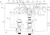
- FIG. 1 Ais a perspective view of a flushing system 100 , in accordance with one aspect of the present disclosure.
- the flushing system 100can be configured to flush fluid, such as water, from a fluid system, such as, for example, a municipal water system, or any other fluid system where it may be desirable to periodically flush fluid out of the fluid system. For example, it may be desirable to flush stagnant or contaminated water out of the fluid system.
- example aspects of the flushing system 100can comprise a housing 110 defining an interior cavity 115 within which various components of the flushing system 100 can be contained. In the present FIG. 1 A , the housing 110 is illustrated as transparent for visibility of the components within the interior cavity 115 .
- the housing 110can comprise a sidewall enclosure 120 comprising a plurality of sidewalls 122 and defining an upper end 124 and a lower end 126 , relative to the orientation shown.
- an access opening 128 providing access to the interior cavity 115can be formed at the upper end 124 .
- the housing 110can further comprise a lid 425 (shown in FIG. 4 ) oriented at the upper end 124 of the sidewall enclosure 120 and a base 129 (shown in FIG. 1 B ) oriented at the lower end 126 of the sidewall enclosure 120 .
- the lid 425can be configured to selectively uncover the access opening 128 , as shown, and cover the access opening 128 , as shown in FIG.
- the housing 110can be buried below or mostly below ground, and that the lid 425 can be oriented about flush with ground level. As such, the lid 425 can be removed from the sidewall enclosure 120 as needed, without the flushing system 100 extending above ground.
- Example aspects of the housing 110can be formed from a composite material, a plastic material, such as polyvinyl chloride (PVC), a metal material, or any other suitable material or combination of materials known in the art.
- PVCpolyvinyl chloride
- the flushing system 100can comprise a substantially U-shaped fluid routing assembly 130 configured to route fluid from the fluid system through the flushing system 100 .
- the fluid routing assembly 130may not define a U-shape.
- Example aspects of the fluid routing assembly 130can comprise a sampling port 135 , a backflow preventer 140 , and a valve 143 .
- the valve 143can be an adjustable flow valve 145 , as shown, and can be configured to control the flow of fluid through the flushing system 100 .
- the valve 143can be any other suitable type of valve known in the art.
- some or all of the internal components of the adjustable flow valve 145can comprise a stainless steel material; however, in other aspects, the internal components of the adjustable flow valve 145 can comprise any other suitable material or combination of materials.
- An inlet pathway 150can be provided for routing fluid into the fluid routing assembly 130 and an outlet pathway 160 can be provided for routing the fluid out of the fluid routing assembly 130 .
- fluid from the fluid systemcan flow into the flushing system 100 through the inlet pathway 150 , past the sampling port 135 , through the backflow preventer 140 , through the adjustable flow valve 145 , and out of the flushing system 100 through the outlet pathway 160 .
- the fluidcan further be configured to flow through a dechlorination unit 170 .
- the sampling port 135can be oriented between the inlet pathway 150 and the backflow preventer 140 .
- the sampling port 135can comprise a sampling conduit 136 configured to dispense samples of the fluid in the fluid routing assembly 130 for testing the quality of the fluid.
- the fluidcan be tested for levels of lead, bacteria, nitrates, chlorine, pH levels, or the like.
- the fluidcan be dispensed into a collection container and can be tested on site or taken to a testing facility.
- samples of the fluidcan be obtained from the flushing system 100 even when the flushing system 100 is not actively flushing.
- the backflow preventer 140can be oriented between the sampling port 135 and the adjustable flow valve 145 .
- the backflow preventer 140can be configured to allow fluid to flow therethrough in a first direction towards the outlet pathway 160 , but can prevent the fluid from flowing in an opposite second direction back towards the inlet pathway 150 . As such, the fluid in the fluid system can be protected from contamination by the fluid in the flushing system 100 backflowing into the fluid system.
- the backflow preventer 140can be a double check valve 141 , though in other aspects, the backflow preventer 140 can define any other suitable configuration known in the art, such as an air gap.
- Example aspects of the backflow preventer 140can comprise one or more relief valves 142 , as shown. The relief valves 142 may be spaced apart along the backflow preventer 140 to relive air buildup within the backflow preventer 140 at various points.
- the adjustable flow valve 145can be oriented between the backflow preventer 140 and the outlet pathway 160 .
- the adjustable flow valve 145can be configured to control the operation of the flushing system 100 .
- the adjustable flow valve 145can be selectively oriented in an open configuration and a closed configuration. In the open configuration, fluid can flow through the adjustable flow valve 145 , and the flushing system 100 can flush the fluid through the fluid routing assembly 130 . In the closed configuration, the fluid can be prevented from flowing through the adjustable flow valve 145 , and the flushing system 100 can thus be prevented flushing the fluid through the fluid routing assembly 130 .
- Example aspects of the adjustable flow valve 145can be a solenoid-operated adjustable flow valve 145 , though in other aspects, the adjustable flow valve 145 can be a hydraulic adjustable flow valve, pneumatic adjustable flow valve, or any other suitable type of adjustable flow valve. In still other aspects, the valve 143 may not be an adjustable flow valve 145 , and can instead comprise any other suitable type of valve known in the art. In aspects of the adjustable flow valve 145 that are solenoid-operated, a solenoid 146 (shown in FIG.
- adjustable flow valve 145can be configured to selectively either admit or release pressure into a main chamber of the adjustable flow valve 145 , thus orienting the adjustable flow valve 145 in the closed and open configurations, respectively, in order to prevent or permit fluid flow through the adjustable flow valve 145 , respectively.
- the adjustable flow valve 145can further be oriented in any suitable number of partially-open configurations to selectively regulate the fluid flow through the adjustable flow valve 145 .
- Example aspects of the adjustable flow valve 145can further comprise a strainer therein configured to filter debris out the fluid flowing therethrough.
- Example aspects of the flushing system 100can further comprise a control device 175 configured to allow an operator to remotely control the operation of the flushing system 100 , i.e., to remotely control the selective orientation of the adjustable flow valve 145 in the open, closed, and partially-opened configurations, from a remote operation device 610 (shown in FIG. 6 ).
- the control device 175can be completely wireless, while in other aspects, the control device 175 can be wired to the adjustable flow valve 145 .
- the flushing system 100can comprise one or both of a pressure monitoring system 180 and a Bluetooth® controller 190 , and one or both of the pressure monitoring system 180 and Bluetooth® controller 190 can serve as the control device 175 .
- control device 175can also be configured to control the speed at which the adjustable flow valve 145 opens and closes, which can aid in preventing water hammer.
- Bluetooth®is one example of short distance wireless communication protocols, and can be used to implement personal-area networks (PANs)
- PANspersonal-area networks
- the Bluetooth® controller 190can be connected to the solenoid by one or more wires 147 (shown in FIG. 1 B ).
- the Bluetooth® controller 190configured to wirelessly actuate the solenoid 146 .
- Example aspects of the Bluetooth® controller 190can also be wirelessly connected to the remote operation device 610 , which can allow an operator to remotely send signals to the Bluetooth® controller 190 from the remote operation device 610 .
- any other suitable wireless communication technique(s)may be implemented for remotely controlling the adjustable flow valve 145 with the control device 175 .
- the remote operation device 610can be, for example, a mobile phone, tablet, computer, or the like.
- a program or appcan be downloaded onto the remote operation device 610 , through which the operator can send signals to the Bluetooth® controller 190 .
- the remote operation device 610can be configured to send a control signal(s) 615 (shown in FIG. 6 ) to the Bluetooth® controller 190 , and the Bluetooth® controller 190 can actuate the adjustable flow valve 145 in response to the control signal(s) 615 .
- an operatorcan remotely actuate the adjustable flow valve 145 with the remote operation device 610 in order to remotely operate the flushing system 100 .
- the adjustable flow valve 145 of the flushing system 100does not need to be physically accessed by an operator in order to be operated.
- the operatormay be able to operate the flushing system 100 at a distance from Bluetooth® controller 190 .
- an operatormay be able to operate the flushing system 100 from across the street from the flushing system 100 . This can be beneficial in various instances, such as, for example, when the weather is poor and the operator wishes to stay inside their vehicle, or if the flushing system 100 is located in an area that is difficult to access.
- the Bluetooth® controller 190can be mounted to the sidewall enclosure 120 of the housing 110 , though in other aspects, the Bluetooth® controller 190 can be mounted at any suitable location within the interior cavity 115 , including mounted to the fluid routing assembly 130 , the lid 425 , or the base 129 . Some aspects of the Bluetooth® controller 190 may be configured to control various other features of the flushing system 100 and/or may be configured to communicate information, such as water quality information, to one or more external electronic device(s) 620 (shown in FIG. 6 ). In a particular example aspect, the external electronic device(s) 620 can be or include a computer at a remote operations center. Furthermore, in some aspects, the external electronic device(s) 620 can be or can include the remote operation device 610 .
- the flushing system 100can also or alternatively comprise the pressure monitoring system 180 .
- the pressure monitoring system 180can be similar to the monitoring device disclosed in U.S. patent application Ser. No. 15/171,722, filed Jun. 2, 2016, which is hereby specifically incorporated by reference herein in its entirety.
- Example aspects of the pressure monitoring system 180can comprise a pressure sensor 182 (shown in FIG. 1 B ) and a pressure monitoring unit 185 .
- the pressure sensor 182can be, for example, a piezo-resistive strain gauge, a capacitive gauge, an electromagnetic gauge, a piezoelectric device, or any other suitable device known in the art for detecting pressure.
- the pressure sensor 182can be mounted within the fluid routing assembly 130 such that the pressure sensor 182 , or a portion thereof, is in contact with the fluid therein.
- the pressure sensor 182can be wired to the pressure monitoring unit 185 by one or more wires 183 (shown in FIG. 1 B ) and can transmit pressure data obtained by the pressure sensor 182 through the wires 183 to the pressure monitoring unit 185 .
- the pressure sensor 182may be configured to wirelessly transmit the pressure data to the pressure monitoring unit 185 .
- the pressure sensor 182can be configured to continually communicate pressure data to the pressure monitoring unit 185 , while in other aspects, the pressure sensor 182 can communicate pressure data periodically or only when an anomaly is detected.
- the pressure monitoring unit 185can be configured to evaluate the pressure data to determine whether a concern is present.
- the pressure monitoring unit 185may comprise a printed circuit board or other processing unit configured to process and evaluate the pressure data.
- Example aspects of the pressure monitoring unit 185can also be configured to send a pressure signal 685 (shown in FIG. 6 ) representative of the detected pressure to a designated electronic device(s) 620 , which may include the remote operation device 610 , as described in further detail below.
- the pressure monitoring unit 185may be configured to send an alert signal to the designated electronic device(s) 620 .
- the pressure monitoring unit 185can be the control device 175 and can be configured to control the operation of the solenoid 146 , and thus, the Bluetooth® controller 190 may not be required. As shown, the pressure monitoring unit 185 can be connected to the solenoid 146 by one or more wires 148 , or may be wirelessly connected to the solenoid 146 . In example aspects, the solenoid 146 can be connected to only one of the Bluetooth® controller 190 and the pressure monitoring unit 185 , though in other aspects, the solenoid 146 may be connected to both.
- the pressure monitoring unit 185may be configured to control various other features of the flushing system 100 and/or may be configured to communicate information, such as water quality information, to the designated external electronic device(s) 620 .
- the pressure monitoring unit 185can be mounted to the sidewall enclosure 120 of the housing 110 , though in other aspects, the pressure monitoring unit 185 can be mounted at any suitable location within the interior cavity 115 , including mounted to the fluid routing assembly 130 , the lid 425 , or the base 129 .
- the flushing system 100can further comprise the dechlorination unit 170 received within the housing 110 .
- the dechlorination unit 170can be mounted to the housing 110 , for example, to the sidewall enclosure 120 , and in other aspects, the dechlorination unit 170 can be mounted to the fluid routing assembly 130 .
- the dechlorination unit 170can be configured to dechlorinate fluid as it flows therethrough.
- the dechlorination unit 170can comprise dechlorination tablets therein which can dechlorinate the fluid as the fluid passes over the dechlorination tablets.
- the dechlorination tabletscan comprise sodium sulfite, ascorbic acid, or any other suitable substance for dechlorinating fluid.
- some or all of the fluid being flushed through the flushing system 100can be routed through the dechlorination unit 170 for dechlorination.
- the fluidcan be transferred from the fluid routing assembly 130 to the dechlorination unit 170 through a dechlorination inlet conduit 172 , and, once dechlorinated, the fluid can be transferred from the dechlorination unit 170 back to the fluid routing assembly 130 through a dechlorination outlet conduit 174 .
- the dechlorination inlet conduit 172can extend from the valve 143 to the dechlorination unit 170
- the dechlorination outlet conduit 174can extend from the dechlorination unit 170 to the outlet pathway 160 , downstream of the valve 143 .
- the dechlorination unit 170may comprise a dechlorination valve that can be selectively adjusted to control the rate of dechlorination.
- various local, state, or national standardsmay exist for the dechlorination of fluid flushed from a fluid system, and the dechlorination unit 170 can be designed to meet or exceed these standards.
- FIG. 1 Billustrates a top view of the flushing system 100 , wherein the lid 425 (shown in FIG. 4 ) is removed for visibility into the interior cavity 115 .
- the pressure sensor 182can be mounted to the valve 143 at an, and the pressure monitoring unit 185 can be connected to the pressure sensor 182 by the wire 183 .
- the pressure monitoring unit 185can also be connected to the solenoid 146 by the wire 148 .
- Some aspects of the flushing system 100can also or alternatively include the Bluetooth® controller 190 , which can be connected to the solenoid 146 by the wires 147 .
- the pressure monitoring unit 185may be wirelessly connected to either or both of the pressure sensor 182 and the solenoid 146 and/or the Bluetooth® controller 190 may be wirelessly connected to the solenoid 146 .
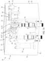
- FIG. 2illustrates a top perspective view of the fluid routing assembly 130 .
- the inlet pathway 150can comprise an inlet conduit 252 that can be connected to the fluid system and can provide a path for the fluid in the fluid system to enter the fluid routing assembly 130 .
- the inlet conduit 252can be configured to extend into the interior cavity 115 through an inlet opening 532 (shown in FIG. 5 ) formed in the base 129 (shown in FIG. 1 B ) of the housing 110 (shown in FIG. 1 A ).
- an inlet mounting bracket 253can be mounted to the inlet conduit 252 , and the inlet mounting bracket 253 can be attached to the base 129 to secure the inlet conduit 252 to the housing 110 .
- one or more fastenerssuch as nut and bolt fasteners 255 , may be provided for securing the inlet mounting bracket 253 to the base 129 .
- the inlet pathway 150can be configured to extend substantially upward, relative to the orientation shown, towards the upper end 124 (shown in FIG. 1 A ) of the sidewall enclosure 120 (shown in FIG. 1 A ).
- an inlet connector 254can be provided for connecting the inlet conduit 252 to an inlet pipe 256 .
- one or both of the inlet conduit 252 and inlet pipe 256can be threadably coupled to the inlet connector 254 .
- An inlet elbow fitting 258can be coupled to the inlet pipe 256 and can define a bend angle of about 90°. As such, the fluid can flow from the fluid system into the inlet conduit 252 , and can then flow through the inlet connector 254 , inlet pipe 256 , and inlet elbow fitting 258 .
- Example aspects of the inlet pathway 150can comprise more or fewer components as needed to route the fluid to the backflow preventer 140 .
- Example aspects of the outlet pathway 160can comprise an outlet conduit 262 that can provide a path for the fluid to exit the fluid routing assembly 130 .
- the outlet conduit 262can be connected to a fluid discharge location, such as sewage system, storm system, swale, retention system, or the like.
- the fluid flushed through the flushing system 100can be routed through the dechlorination unit 170 (shown in FIG. 1 A ) prior to being discharged at the fluid discharge location.
- the outlet conduit 262can be configured to extend into the interior cavity 115 through an outlet opening 534 (shown in FIG. 5 ) formed in the base 129 (shown in FIG. 1 B ) of the housing 110 (shown in FIG. 1 A ).
- an outlet mounting bracket 263can be mounted to the outlet conduit 262 , and the outlet mounting bracket 263 can be attached to the base 129 to secure the outlet conduit 262 to the housing 110 .
- one or more fastenerssuch as nut and bolt fasteners 265 , may be provided for securing the outlet mounting bracket 263 to the base 129 .
- the outlet pathway 160can be configured to extend substantially upward, relative to the orientation shown, towards the upper end 124 of the sidewall enclosure 120 .
- the outlet pathway 160can further comprise an outlet connector 264 for connecting the outlet conduit 262 to an outlet pipe 266 .
- the outlet conduit 262 and outlet pipe 266can be threadably coupled to the outlet connector 264 .
- the fluid in the flushing system 100can exit the flushing system 100 by flowing into the outlet pipe 266 , and then through the outlet connector 264 and the outlet conduit 262 .
- Example aspects of the outlet pathway 160can comprise more or fewer components as needed to route the fluid out of the flushing system 100 .
- either or both of the inlet pathway 150 and outlet pathway 160comprise any suitable configuration for routing the fluid into and out of the flushing system 100 .
- a backflow preventer inlet 210can oriented between and coupled to the inlet elbow fitting 258 and to an inlet end 242 of the backflow preventer 140 , such that fluid can flow from the inlet elbow fitting 258 , through the backflow preventer inlet 210 , and into the backflow preventer 140 .
- the backflow preventer inlet 210can be threadably coupled to the inlet elbow fitting 258 .
- the sampling port 135extend from and can be in fluid communication with the backflow preventer inlet 210 .
- the sampling port 135can be oriented proximate to the upper end 124 of the sidewall enclosure 120 , such that the sampling port 135 can be easily accessed when the lid 425 is removed from the housing 110 to allow access to the interior cavity 115 . In other aspects, however, the sampling port 135 can be oriented at any other suitable location in the flushing system 100 .
- the backflow preventer inlet 210can comprise an inlet shutoff valve 212 , such as a ball valve, which, in the present aspect, can be manually operated to selectively shut off fluid flow into the backflow preventer 140 .
- Example aspects of the fluid routing assembly 130can further comprise a backflow preventer outlet 220 oriented between and coupled to an outlet end 244 of the backflow preventer 140 and an inlet end 246 of the adjustable flow valve 145 .
- fluidcan be configured to flow from the backflow preventer 140 , through the backflow preventer outlet 220 , and into the adjustable flow valve 145 .
- the outlet pipe 266 of the outlet pathway 160can be connected to an outlet end 248 of the adjustable flow valve 145 , such that fluid can flow out of the adjustable flow valve 145 at the outlet end 248 and into the outlet pathway 160 .
- the backflow preventer outlet 220can be threadably coupled to a threaded valve connector 224 , and the threaded valve connector 224 can be threadably coupled to the inlet end 246 of the adjustable flow valve 145 .
- the backflow preventer outlet 220can comprise an outlet shutoff valve 222 , such as a ball valve, which can be manually operated to selectively shut of fluid flow out of the backflow preventer 140 .
- the inlet and outlet shutoff valves 212 , 222may not be manually-operated, and may instead be automatically operated.
- each of the backflow preventer 140 and adjustable flow valve 145can be oriented proximate to the upper end 124 of the sidewall enclosure 120 , to allow for easy access thereto through the access opening 128 for operation of the inlet and outlet shutoff valves 212 , 222 or for the repair or replacement of parts.
- the backflow preventer inlet 210can be coupled to the backflow preventer outlet 220 by one or more connecting brackets 230 .
- the backflow preventer inlet 210can be coupled to the backflow preventer outlet 220 by a first connecting bracket 230 a and a second connecting bracket 230 b .
- the second connecting bracket 230 bis largely hidden from view by the backflow preventer 140 , but can be substantially the same as the first connecting bracket 230 a.
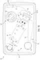
- FIG. 3illustrates the Bluetooth® controller 190 and pressure monitoring unit 185 mounted to the sidewall enclosure 120 of the housing 110 .
- the sidewall enclosure 120is again illustrated as transparent for visibility into the interior cavity 115 .
- other aspects of the flushing system 100may comprise only one of the Bluetooth® controller 190 and the pressure monitoring unit 185 .
- the pressure monitoring system 180can comprise an antenna configured to send pressure signals 685 (shown in FIG. 6 ) representative of the pressure data received from the pressure sensor 182 (shown in FIG. 1 B ) to a designated external electronic device(s) 620 (shown in FIG. 6 ), which as described, may be or may include the remote operation device 610 .
- the housing 110can be formed from a non-ferrous material, so that the material does not interfere with the ability of the antenna to send the pressure signals 685 and other signals externally.
- the antennacan be configured to send signals, including the pressure signals 685 , over a cellular network.
- signalscan be sent from the pressure monitoring unit 185 over wifi, ethernet, Bluetooth®, or any other suitable wireless technology.
- the pressure monitoring unit 185may be configured to report the pressure data externally continually, at user-defined intervals, or may be configured to report the pressure data solely when an anomaly occurs, such as a spike in pressure.
- the antennacan also allow an operator to remotely control the operation of the flushing system 100 .
- the antennacan allow the operator to wirelessly control the solenoid 146 (shown in FIG. 1 B ) to selectively orient the adjustable flow valve 145 in the open, closed, and partially-open configurations.
- the antennacan be wirelessly connected to an app or program on the remote operation device 610 through which the operator can control the flushing system 100 .
- the adjustable flow valve 145can also be programmed to automatically open and close periodically for routine flushing of the fluid system.
- the pressure of the fluidcan drop and a pressure signal 685 can be sent by the antenna relaying the pressure drop information to the designated external electronic device(s) 620 .
- the external electronic device(s) 620can be or can include the remote operation device 610 .
- the pressure of the fluidcan increase when the adjustable flow valve 145 moves to the closed configuration, and a pressure signal 685 can sent relaying the pressure increase information to the designated external electronic device(s) 620 .
- the antennamay allow for remote control of various other features of the flushing system 100 .
- the antennamay be configured to communicate information related to other aspects of the flushing system 100 or the fluid therein to one or more external electronic device(s) 620 .
- the flushing system 100may comprise a temperature sensor 184 configured to detect a temperature of the fluid and the antenna can be configured to send a temperature signal representative of the detected temperature to the designated electronic device(s) 620 .
- the temperature sensor 184can be housed with the pressure sensor 182 and can be wired to the pressure monitoring unit 185 by the wire 183 .
- Example aspects of the flushing system 100may further comprise various other sensors, detectors, and/or measurement tools for sensing, detecting, and/or measuring other properties of the fluid, such as, for example, fluid quality, flow rate, pH level, chlorine level, disinfectant level, turbidity, and the like.
- the antennacan communicate information related to detected fluid property or properties via a fluid property signal.
- the antennacan also be configured to communicate information such as the concentration of the dechlorination substances (e.g., sodium sulfite, ascorbic acid) within the dechlorination unit 170 , a status of the strainer in the adjustable flow valve 145 , etc.
- the Bluetooth® controller 190may allow for remote control the same or different features of the flushing system 100 and/or communication of the same or different information.
- the pressure monitoring unit 185can be mounted to the sidewall enclosure 120 by a pressure monitor bracket 310 and the Bluetooth® controller 190 can be mounted to the sidewall enclosure 120 by one or more mounting tabs 320 .
- the Bluetooth® controller 190can be mounted to a first one of the sidewalls 122 a of the sidewall enclosure 120 and the pressure monitoring unit 185 can be mounted to a second one of the sidewalls 122 b .
- the Bluetooth® controller 190 and sidewall enclosure 120can be mounted at any other suitable location within the interior cavity 115 , including any location on the sidewall enclosure 120 , lid 425 (shown in FIG. 4 ), base 129 (shown in FIG.
- example aspects of the pressure monitor bracket 310comprise a bracket ring 312 and a bracket mounting flange 314 .
- the bracket ring 312can wrap around a body 386 of the pressure monitoring unit 185 and a head 388 of the pressure monitoring unit 185 can rest on the bracket ring 312 .
- the bracket mounting flange 314can abut the second sidewall 122 b of the sidewall enclosure 120 and can define one or more fastener holes 316 formed therethrough, as shown.
- a fastenersuch as, for example, a screw, can extend through each of the fastener holes 316 and can engage the second sidewall 122 b to mount the pressure monitor bracket 310 to the sidewall enclosure 120 .
- Example aspects of the Bluetooth® controller 190can comprise two of the mounting tabs 320 formed monolithically with the Bluetooth® controller 190 , and the mounting tabs 320 can abut the first sidewall 122 a of the sidewall enclosure 120 . In other aspects, the mounting tabs 320 can be formed separately from the Bluetooth® controller 190 and attached thereto.
- Each of the mounting tabs 320can define a fastener hole 326 formed therethrough, and a fastener, such as a screw, for example, can extend through each of the fastener holes 326 of the mounting tabs 320 and can engage the first sidewall 122 a to mount the Bluetooth® controller 190 to the sidewall enclosure 120 .
- a fastenersuch as a screw
- the Bluetooth® controller 190 and pressure monitoring unit 185can be secured to the housing 110 or elsewhere in the interior cavity 115 by any other suitable attachments mechanisms known in the art.
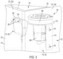
- FIG. 4illustrates a top perspective view of the housing 110 with the lid 425 covering access opening 128 (shown in FIG. 1 A ) to prevent access to the interior cavity 115 (shown in FIG. 1 A ).
- the lid 425may be configured to rest on a rim or stops of the sidewall enclosure 120 to support the lid 425 proximate to the upper end 124 of the sidewall enclosure 120 .
- a friction fitmay be defined between the lid 425 and sidewall enclosure 120 to secure the lid 425 in position at the upper end 124
- the housing 110can define any other suitable configuration for retaining the lid 425 at the upper end 124 of the sidewall enclosure 120 .
- the lid 425may be removable from the sidewall enclosure 120 to uncover the access opening 128 and allow access to the interior cavity 115 .
- the lid 425may be removed for the manual operation of the inlet and outlet shutoff valves 212 , 222 (shown in FIG. 2 ), for obtaining fluid samples from the sampling port 135 (shown in FIG. 1 A ), for replacing the strainer in the adjustable flow valve 145 (shown in FIG. 1 A ), for adding additional dechlorination tablets to the dechlorination unit 170 shown in FIG. 1 A ), for repairing or replacing any of the components housed within the interior cavity 115 , or for any other suitable reason.
- Example aspects of the lid 425may comprise a handle or handles to facilitate lifting the lid 425 away from the sidewall enclosure 120 . Moreover, in some aspects, a tool may be required to remove the lid 425 in order to prohibit manual removal of the lid 425 and prevent unintentional removal of the lid 425 and/or tampering with the flushing system 100 . In other aspects, the lid 425 may not be removable from housing 110 .
- FIG. 5illustrates a bottom perspective view of the housing 110 , illustrating the base 129 oriented at the lower end 126 of the sidewall enclosure 120 .
- the base 129can be monolithically formed with sidewall enclosure 120 , and in other aspects, the base 129 can be separately formed from the sidewall enclosure 120 and attached thereto.
- some example aspects of the base 129can be removable from the sidewall enclosure 120 , while in other aspects, the base 129 is not removable.
- example aspects of the base 129can define the inlet opening 532 formed therethrough through which the inlet conduit 252 (shown in FIG. 2 ) can extend and the outlet opening 534 formed therethrough through which the outlet conduit 262 (shown in FIG. 2 ) can extend.
- Other aspects of the base 129may comprise additional openings to allow additional components of the flushing system 100 , or other systems, to extend into and/or out of the interior cavity 115 (shown in FIG. 1 A ).
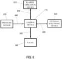
- FIG. 6is a system diagram illustrating a method of operating the flushing system 100 , according to an example aspect of the disclosure.
- Example aspects of the methodcan include providing the flushing system 100 comprising the fluid routing assembly 130 (shown in FIG. 1 A ) and the control device 175 , wherein the fluid routing assembly 130 can comprise the valve 143 .
- the valvecan be configurable in the open configuration, wherein fluid is permitted to flow through the fluid routing assembly 130 , and a closed configuration, wherein the fluid is prohibited from flowing through the fluid routing assembly 130 .
- the methodcan further comprising remotely sending a control signal 615 to the control device 175 .
- the control signal 615can be sent by the remote operation device 610 .
- Example aspects of the methodcan also comprise actuating the valve 143 between the open configuration and closed configuration with the control device 175 in response to the control signal 615 , wherein, in some aspects, the control device 175 can wirelessly actuate the valve 143 by sending an actuation signal 645 to the valve 143 .
- the methodcan further comprise detecting a pressure of the fluid with the pressure sensor 182 , and sending the pressure signal 685 with the control device 175 , the pressure signal 685 representative of the pressure detected by the pressure sensor 182 .
- the pressure signal 685can be sent to an external electronic device 620 or devices, and in some aspects, the external electronic devices(s) 620 can be or can comprise the remote operation device 610 .
- the pressure sensor 182can send pressure data wirelessly to the control device 175 , while in other aspects, the pressure sensor 182 can be wired to the control device 175 and can transmit data to the control device 175 through a pressure sensor wire 640 , as shown.
- conditional languagesuch as, among others, “can,” “could,” “might,” or “may,” unless specifically stated otherwise, or otherwise understood within the context as used, is generally intended to convey that certain embodiments include, while other embodiments do not include, certain features, elements and/or steps. Thus, such conditional language is not generally intended to imply that features, elements and/or steps are in any way required for one or more particular embodiments or that one or more particular embodiments necessarily include logic for deciding, with or without user input or prompting, whether these features, elements and/or steps are included or are to be performed in any particular embodiment.
Landscapes
- Engineering & Computer Science (AREA)
- Water Supply & Treatment (AREA)
- Life Sciences & Earth Sciences (AREA)
- Hydrology & Water Resources (AREA)
- Chemical & Material Sciences (AREA)
- General Physics & Mathematics (AREA)
- Physics & Mathematics (AREA)
- Organic Chemistry (AREA)
- Health & Medical Sciences (AREA)
- Environmental & Geological Engineering (AREA)
- Public Health (AREA)
- Mechanical Engineering (AREA)
- Medicinal Chemistry (AREA)
- Indication Of The Valve Opening Or Closing Status (AREA)
- Measuring Fluid Pressure (AREA)
- Sampling And Sample Adjustment (AREA)
Abstract
Description
This disclosure relates to flushing systems. More specifically, this disclosure relates to a remotely-operable flushing system for fluid distribution systems.
Flushing systems can be used to periodically flush fluid from fluid systems, such as water systems. Flushing water systems can be done for a variety of reasons, including improving the quality of the water. Flushing systems are typically contained within a housing comprising a removable lid. To operate the flushing system, an operator must typically remove the lid from the housing and manually activate the flushing system. An operator must also typically be physically present to obtain various information related to fluid within the flushing system or the flushing system itself.
It is to be understood that this summary is not an extensive overview of the disclosure. This summary is exemplary and not restrictive, and it is intended neither to identify key or critical elements of the disclosure nor delineate the scope thereof. The sole purpose of this summary is to explain and exemplify certain concepts of the disclosure as an introduction to the following complete and extensive detailed description.
Disclosed is a remote-operated flushing system comprising a fluid routing assembly comprising a valve, the valve configurable in an open configuration, wherein fluid is permitted to flow through the fluid routing assembly, and a closed configuration, wherein the fluid is prohibited from flowing through the fluid routing assembly; a control device configured to actuate the valve between the open configuration and closed configuration; a remote operation device wirelessly connected to the control device and configured to remotely operate the control device to control the actuation of the valve between the open configuration and closed configuration; and a sensor configured to detect a fluid property of the fluid within the fluid routing assembly, wherein the control device is configured to wirelessly send a signal representative of the fluid property detected by the sensor.
Also disclosed is a remote-operated flushing system comprising a fluid routing assembly comprising a valve, the valve configurable in an open configuration, wherein fluid is permitted to flow through the fluid routing assembly, and a closed configuration, wherein the fluid is prohibited from flowing through the fluid routing assembly; and a pressure monitoring system, the pressure monitoring system comprising: a pressure sensor mounted to the fluid routing assembly and configured to detect a pressure of the fluid within the fluid routing assembly; and a pressure monitoring unit configured to wirelessly send a pressure signal representative of the pressure detected by the pressure sensor, the pressure monitoring unit further configured to wirelessly receive a control signal from a remote operation device and to actuate the valve between the open configuration and closed configuration in response to the control signal.
Also disclosed is a method of operating a flushing system, the method comprising providing a flushing system comprising a fluid routing assembly and a control device, the fluid routing assembly comprising a valve configurable in an open configuration, wherein fluid is permitted to flow through the fluid routing assembly, and a closed configuration, wherein the fluid is prohibited from flowing through the fluid routing assembly; remotely sending a control signal to a control device; actuating the valve between the open configuration and closed configuration with the control device in response to the control signal; detecting a pressure of the fluid with a pressure sensor; and sending a signal with the control device, the signal representative of the pressure detected by the pressure sensor.
Various implementations described in the present disclosure may include additional systems, methods, features, and advantages, which may not necessarily be expressly disclosed herein but will be apparent to one of ordinary skill in the art upon examination of the following detailed description and accompanying drawings. It is intended that all such systems, methods, features, and advantages be included within the present disclosure and protected by the accompanying claims.
The features and components of the following figures are illustrated to emphasize the general principles of the present disclosure. Corresponding features and components throughout the figures may be designated by matching reference characters for the sake of consistency and clarity.
The present disclosure can be understood more readily by reference to the following detailed description, examples, drawings, and claims, and the previous and following description. However, before the present devices, systems, and/or methods are disclosed and described, it is to be understood that this disclosure is not limited to the specific devices, systems, and/or methods disclosed unless otherwise specified, and, as such, can, of course, vary. It is also to be understood that the terminology used herein is for the purpose of describing particular aspects only and is not intended to be limiting.
The following description is provided as an enabling teaching of the present devices, systems, and/or methods in its best, currently known aspect. To this end, those skilled in the relevant art will recognize and appreciate that many changes can be made to the various aspects of the present devices, systems, and/or methods described herein, while still obtaining the beneficial results of the present disclosure. It will also be apparent that some of the desired benefits of the present disclosure can be obtained by selecting some of the features of the present disclosure without utilizing other features. Accordingly, those who work in the art will recognize that many modifications and adaptations to the present disclosure are possible and can even be desirable in certain circumstances and are a part of the present disclosure. Thus, the following description is provided as illustrative of the principles of the present disclosure and not in limitation thereof.
As used throughout, the singular forms “a,” “an” and “the” include plural referents unless the context clearly dictates otherwise. Thus, for example, reference to “an element” can include two or more such elements unless the context indicates otherwise.
Ranges can be expressed herein as from “about” one particular value, and/or to “about” another particular value. When such a range is expressed, another aspect includes from the one particular value and/or to the other particular value. Similarly, when values are expressed as approximations, by use of the antecedent “about,” it will be understood that the particular value forms another aspect. It will be further understood that the endpoints of each of the ranges are significant both in relation to the other endpoint, and independently of the other endpoint.
For purposes of the current disclosure, a material property or dimension measuring about X or substantially X on a particular measurement scale measures within a range between X plus an industry-standard upper tolerance for the specified measurement and X minus an industry-standard lower tolerance for the specified measurement. Because tolerances can vary between different materials, processes and between different models, the tolerance for a particular measurement of a particular component can fall within a range of tolerances.
As used herein, the terms “optional” or “optionally” mean that the subsequently described event or circumstance can or cannot occur, and that the description includes instances where said event or circumstance occurs and instances where it does not.
The word “or” as used herein means any one member of a particular list and also includes any combination of members of that list. Further, one should note that conditional language, such as, among others, “can,” “could,” “might,” or “may,” unless specifically stated otherwise, or otherwise understood within the context as used, is generally intended to convey that certain aspects include, while other aspects do not include, certain features, elements and/or steps. Thus, such conditional language is not generally intended to imply that features, elements and/or steps are in any way required for one or more particular aspects or that one or more particular aspects necessarily include logic for deciding, with or without user input or prompting, whether these features, elements and/or steps are included or are to be performed in any particular aspect.
Disclosed are components that can be used to perform the disclosed methods and systems. These and other components are disclosed herein, and it is understood that when combinations, subsets, interactions, groups, etc. of these components are disclosed that while specific reference of each various individual and collective combinations and permutations of these may not be explicitly disclosed, each is specifically contemplated and described herein, for all methods and systems. This applies to all aspects of this application including, but not limited to, steps in disclosed methods. Thus, if there are a variety of additional steps that can be performed it is understood that each of these additional steps can be performed with any specific aspect or combination of aspects of the disclosed methods.
Disclosed is a remote-operated flushing system and associated methods, systems, devices, and various apparatus. Example aspects of the remote-operated flushing system can comprise a valve configured to control fluid flow through the flushing system and a control device to allow remote operation of the valve. It would be understood by one of skill in the art that the flushing system is described in but a few exemplary embodiments among many. No particular terminology or description should be considered limiting on the disclosure or the scope of any claims issuing therefrom.
According to example aspects, theflushing system 100 can comprise a substantially U-shapedfluid routing assembly 130 configured to route fluid from the fluid system through theflushing system 100. In other aspects, thefluid routing assembly 130 may not define a U-shape. Example aspects of thefluid routing assembly 130 can comprise asampling port 135, abackflow preventer 140, and avalve 143. In example aspects, thevalve 143 can be an adjustable flow valve145, as shown, and can be configured to control the flow of fluid through theflushing system 100. In other aspects, thevalve 143 can be any other suitable type of valve known in the art. Additionally, in example aspects, some or all of the internal components of the adjustable flow valve145 can comprise a stainless steel material; however, in other aspects, the internal components of the adjustable flow valve145 can comprise any other suitable material or combination of materials. Aninlet pathway 150 can be provided for routing fluid into thefluid routing assembly 130 and anoutlet pathway 160 can be provided for routing the fluid out of thefluid routing assembly 130. In the present aspect, fluid from the fluid system can flow into theflushing system 100 through theinlet pathway 150, past thesampling port 135, through thebackflow preventer 140, through the adjustable flow valve145, and out of theflushing system 100 through theoutlet pathway 160. In some aspects, the fluid can further be configured to flow through adechlorination unit 170.
As shown, thesampling port 135 can be oriented between theinlet pathway 150 and thebackflow preventer 140. According to example aspects, thesampling port 135 can comprise asampling conduit 136 configured to dispense samples of the fluid in thefluid routing assembly 130 for testing the quality of the fluid. For example, the fluid can be tested for levels of lead, bacteria, nitrates, chlorine, pH levels, or the like. The fluid can be dispensed into a collection container and can be tested on site or taken to a testing facility. In some aspects, samples of the fluid can be obtained from theflushing system 100 even when theflushing system 100 is not actively flushing. In example aspects, thebackflow preventer 140 can be oriented between thesampling port 135 and the adjustable flow valve145. Thebackflow preventer 140 can be configured to allow fluid to flow therethrough in a first direction towards theoutlet pathway 160, but can prevent the fluid from flowing in an opposite second direction back towards theinlet pathway 150. As such, the fluid in the fluid system can be protected from contamination by the fluid in theflushing system 100 backflowing into the fluid system. In the present aspect, thebackflow preventer 140 can be a double check valve141, though in other aspects, thebackflow preventer 140 can define any other suitable configuration known in the art, such as an air gap. Example aspects of thebackflow preventer 140 can comprise one ormore relief valves 142, as shown. Therelief valves 142 may be spaced apart along thebackflow preventer 140 to relive air buildup within thebackflow preventer 140 at various points.
According to example aspects, the adjustable flow valve145 can be oriented between thebackflow preventer 140 and theoutlet pathway 160. The adjustable flow valve145 can be configured to control the operation of theflushing system 100. For example, the adjustable flow valve145 can be selectively oriented in an open configuration and a closed configuration. In the open configuration, fluid can flow through the adjustable flow valve145, and theflushing system 100 can flush the fluid through thefluid routing assembly 130. In the closed configuration, the fluid can be prevented from flowing through the adjustable flow valve145, and theflushing system 100 can thus be prevented flushing the fluid through thefluid routing assembly 130. Example aspects of the adjustable flow valve145 can be a solenoid-operated adjustable flow valve145, though in other aspects, the adjustable flow valve145 can be a hydraulic adjustable flow valve, pneumatic adjustable flow valve, or any other suitable type of adjustable flow valve. In still other aspects, thevalve 143 may not be an adjustable flow valve145, and can instead comprise any other suitable type of valve known in the art. In aspects of the adjustable flow valve145 that are solenoid-operated, a solenoid146 (shown inFIG.1B ) can be configured to selectively either admit or release pressure into a main chamber of the adjustable flow valve145, thus orienting the adjustable flow valve145 in the closed and open configurations, respectively, in order to prevent or permit fluid flow through the adjustable flow valve145, respectively. In some aspects, the adjustable flow valve145 can further be oriented in any suitable number of partially-open configurations to selectively regulate the fluid flow through the adjustable flow valve145. Example aspects of the adjustable flow valve145 can further comprise a strainer therein configured to filter debris out the fluid flowing therethrough.
Example aspects of theflushing system 100 can further comprise acontrol device 175 configured to allow an operator to remotely control the operation of theflushing system 100, i.e., to remotely control the selective orientation of the adjustable flow valve145 in the open, closed, and partially-opened configurations, from a remote operation device610 (shown inFIG.6 ). In some aspects, such as the present aspect, thecontrol device 175 can be completely wireless, while in other aspects, thecontrol device 175 can be wired to the adjustable flow valve145. For example, as shown, theflushing system 100 can comprise one or both of apressure monitoring system 180 and aBluetooth® controller 190, and one or both of thepressure monitoring system 180 andBluetooth® controller 190 can serve as thecontrol device 175. In some aspects, thecontrol device 175 can also be configured to control the speed at which the adjustable flow valve145 opens and closes, which can aid in preventing water hammer. Bluetooth® is one example of short distance wireless communication protocols, and can be used to implement personal-area networks (PANs) In aspects wherein theBluetooth® controller 190 is thecontrol device 175 and the adjustable flow valve145 is solenoid-operated, theBluetooth® controller 190 can be connected to the solenoid by one or more wires147 (shown inFIG.1B ). In other aspects, theBluetooth® controller 190 configured to wirelessly actuate thesolenoid 146. Example aspects of theBluetooth® controller 190 can also be wirelessly connected to theremote operation device 610, which can allow an operator to remotely send signals to theBluetooth® controller 190 from theremote operation device 610. In other aspects, any other suitable wireless communication technique(s) may be implemented for remotely controlling the adjustable flow valve145 with thecontrol device 175.
Theremote operation device 610 can be, for example, a mobile phone, tablet, computer, or the like. In example aspects, a program or app can be downloaded onto theremote operation device 610, through which the operator can send signals to theBluetooth® controller 190. For example, theremote operation device 610 can be configured to send a control signal(s)615 (shown inFIG.6 ) to theBluetooth® controller 190, and theBluetooth® controller 190 can actuate the adjustable flow valve145 in response to the control signal(s)615. As such, an operator can remotely actuate the adjustable flow valve145 with theremote operation device 610 in order to remotely operate theflushing system 100. Thus, the adjustable flow valve145 of theflushing system 100 does not need to be physically accessed by an operator in order to be operated. Furthermore, the operator may be able to operate theflushing system 100 at a distance fromBluetooth® controller 190. For example, an operator may be able to operate theflushing system 100 from across the street from theflushing system 100. This can be beneficial in various instances, such as, for example, when the weather is poor and the operator wishes to stay inside their vehicle, or if theflushing system 100 is located in an area that is difficult to access. As shown in the present aspect, theBluetooth® controller 190 can be mounted to thesidewall enclosure 120 of thehousing 110, though in other aspects, theBluetooth® controller 190 can be mounted at any suitable location within theinterior cavity 115, including mounted to thefluid routing assembly 130, thelid 425, or thebase 129. Some aspects of theBluetooth® controller 190 may be configured to control various other features of theflushing system 100 and/or may be configured to communicate information, such as water quality information, to one or more external electronic device(s)620 (shown inFIG.6 ). In a particular example aspect, the external electronic device(s)620 can be or include a computer at a remote operations center. Furthermore, in some aspects, the external electronic device(s)620 can be or can include theremote operation device 610.
According to some example aspects, theflushing system 100 can also or alternatively comprise thepressure monitoring system 180. In some aspects, thepressure monitoring system 180 can be similar to the monitoring device disclosed in U.S. patent application Ser. No. 15/171,722, filed Jun. 2, 2016, which is hereby specifically incorporated by reference herein in its entirety. Example aspects of thepressure monitoring system 180 can comprise a pressure sensor182 (shown inFIG.1B ) and apressure monitoring unit 185. Thepressure sensor 182 can be, for example, a piezo-resistive strain gauge, a capacitive gauge, an electromagnetic gauge, a piezoelectric device, or any other suitable device known in the art for detecting pressure. Thepressure sensor 182 can be mounted within thefluid routing assembly 130 such that thepressure sensor 182, or a portion thereof, is in contact with the fluid therein. Thepressure sensor 182 can be wired to thepressure monitoring unit 185 by one or more wires183 (shown inFIG.1B ) and can transmit pressure data obtained by thepressure sensor 182 through thewires 183 to thepressure monitoring unit 185. In other aspects, thepressure sensor 182 may be configured to wirelessly transmit the pressure data to thepressure monitoring unit 185. In various aspects, thepressure sensor 182 can be configured to continually communicate pressure data to thepressure monitoring unit 185, while in other aspects, thepressure sensor 182 can communicate pressure data periodically or only when an anomaly is detected. Thepressure monitoring unit 185 can be configured to evaluate the pressure data to determine whether a concern is present. For example, thepressure monitoring unit 185 may comprise a printed circuit board or other processing unit configured to process and evaluate the pressure data. Example aspects of thepressure monitoring unit 185 can also be configured to send a pressure signal685 (shown inFIG.6 ) representative of the detected pressure to a designated electronic device(s)620, which may include theremote operation device 610, as described in further detail below. In instances wherein the pressure data presents a concern, thepressure monitoring unit 185 may be configured to send an alert signal to the designated electronic device(s)620. Furthermore, in some aspects, thepressure monitoring unit 185 can be thecontrol device 175 and can be configured to control the operation of thesolenoid 146, and thus, theBluetooth® controller 190 may not be required. As shown, thepressure monitoring unit 185 can be connected to thesolenoid 146 by one ormore wires 148, or may be wirelessly connected to thesolenoid 146. In example aspects, thesolenoid 146 can be connected to only one of theBluetooth® controller 190 and thepressure monitoring unit 185, though in other aspects, thesolenoid 146 may be connected to both. Moreover, in some aspects, thepressure monitoring unit 185 may be configured to control various other features of theflushing system 100 and/or may be configured to communicate information, such as water quality information, to the designated external electronic device(s)620. As shown in the present aspect, thepressure monitoring unit 185 can be mounted to thesidewall enclosure 120 of thehousing 110, though in other aspects, thepressure monitoring unit 185 can be mounted at any suitable location within theinterior cavity 115, including mounted to thefluid routing assembly 130, thelid 425, or thebase 129.
According to example aspects, theflushing system 100 can further comprise thedechlorination unit 170 received within thehousing 110. In some aspects, thedechlorination unit 170 can be mounted to thehousing 110, for example, to thesidewall enclosure 120, and in other aspects, thedechlorination unit 170 can be mounted to thefluid routing assembly 130. Thedechlorination unit 170 can be configured to dechlorinate fluid as it flows therethrough. For example, in some aspects, thedechlorination unit 170 can comprise dechlorination tablets therein which can dechlorinate the fluid as the fluid passes over the dechlorination tablets. The dechlorination tablets can comprise sodium sulfite, ascorbic acid, or any other suitable substance for dechlorinating fluid. According to example aspects, some or all of the fluid being flushed through theflushing system 100 can be routed through thedechlorination unit 170 for dechlorination. As shown, the fluid can be transferred from thefluid routing assembly 130 to thedechlorination unit 170 through adechlorination inlet conduit 172, and, once dechlorinated, the fluid can be transferred from thedechlorination unit 170 back to thefluid routing assembly 130 through adechlorination outlet conduit 174. In the present aspect, thedechlorination inlet conduit 172 can extend from thevalve 143 to thedechlorination unit 170, and thedechlorination outlet conduit 174 can extend from thedechlorination unit 170 to theoutlet pathway 160, downstream of thevalve 143. In some aspects, thedechlorination unit 170 may comprise a dechlorination valve that can be selectively adjusted to control the rate of dechlorination. According to example aspects, various local, state, or national standards may exist for the dechlorination of fluid flushed from a fluid system, and thedechlorination unit 170 can be designed to meet or exceed these standards.
Example aspects of theoutlet pathway 160 can comprise anoutlet conduit 262 that can provide a path for the fluid to exit thefluid routing assembly 130. In example aspects, theoutlet conduit 262 can be connected to a fluid discharge location, such as sewage system, storm system, swale, retention system, or the like. In some aspects, as described above, the fluid flushed through theflushing system 100 can be routed through the dechlorination unit170 (shown inFIG.1A ) prior to being discharged at the fluid discharge location. Theoutlet conduit 262 can be configured to extend into theinterior cavity 115 through an outlet opening534 (shown inFIG.5 ) formed in the base129 (shown inFIG.1B ) of the housing110 (shown inFIG.1A ). In some aspects, anoutlet mounting bracket 263 can be mounted to theoutlet conduit 262, and theoutlet mounting bracket 263 can be attached to the base129 to secure theoutlet conduit 262 to thehousing 110. As shown, one or more fasteners, such as nut andbolt fasteners 265, may be provided for securing theoutlet mounting bracket 263 to thebase 129. According to some example aspects, theoutlet pathway 160 can be configured to extend substantially upward, relative to the orientation shown, towards theupper end 124 of thesidewall enclosure 120. In the present aspect, theoutlet pathway 160 can further comprise anoutlet connector 264 for connecting theoutlet conduit 262 to anoutlet pipe 266. In some aspects, theoutlet conduit 262 andoutlet pipe 266 can be threadably coupled to theoutlet connector 264. As such, as shown, the fluid in theflushing system 100 can exit theflushing system 100 by flowing into theoutlet pipe 266, and then through theoutlet connector 264 and theoutlet conduit 262. Example aspects of theoutlet pathway 160 can comprise more or fewer components as needed to route the fluid out of theflushing system 100. In other aspects, either or both of theinlet pathway 150 andoutlet pathway 160 comprise any suitable configuration for routing the fluid into and out of theflushing system 100.
According to example aspects, abackflow preventer inlet 210 can oriented between and coupled to the inlet elbow fitting258 and to aninlet end 242 of thebackflow preventer 140, such that fluid can flow from the inlet elbow fitting258, through thebackflow preventer inlet 210, and into thebackflow preventer 140. In some aspects, thebackflow preventer inlet 210 can be threadably coupled to theinlet elbow fitting 258. As shown, thesampling port 135 extend from and can be in fluid communication with thebackflow preventer inlet 210. As such, thesampling port 135 can be oriented proximate to theupper end 124 of thesidewall enclosure 120, such that thesampling port 135 can be easily accessed when thelid 425 is removed from thehousing 110 to allow access to theinterior cavity 115. In other aspects, however, thesampling port 135 can be oriented at any other suitable location in theflushing system 100. Additionally, as shown, thebackflow preventer inlet 210 can comprise aninlet shutoff valve 212, such as a ball valve, which, in the present aspect, can be manually operated to selectively shut off fluid flow into thebackflow preventer 140.
Example aspects of thefluid routing assembly 130 can further comprise abackflow preventer outlet 220 oriented between and coupled to anoutlet end 244 of thebackflow preventer 140 and an inlet end246 of the adjustable flow valve145. Thus, fluid can be configured to flow from thebackflow preventer 140, through thebackflow preventer outlet 220, and into the adjustable flow valve145. Furthermore, as shown, theoutlet pipe 266 of theoutlet pathway 160 can be connected to anoutlet end 248 of the adjustable flow valve145, such that fluid can flow out of the adjustable flow valve145 at theoutlet end 248 and into theoutlet pathway 160. In some aspects, thebackflow preventer outlet 220 can be threadably coupled to a threadedvalve connector 224, and the threadedvalve connector 224 can be threadably coupled to the inlet end246 of the adjustable flow valve145. Similar to thebackflow preventer inlet 210, thebackflow preventer outlet 220 can comprise anoutlet shutoff valve 222, such as a ball valve, which can be manually operated to selectively shut of fluid flow out of thebackflow preventer 140. In other aspects, the inlet andoutlet shutoff valves backflow preventer 140 and adjustable flow valve145 can be oriented proximate to theupper end 124 of thesidewall enclosure 120, to allow for easy access thereto through the access opening128 for operation of the inlet andoutlet shutoff valves backflow preventer inlet 210 can be coupled to thebackflow preventer outlet 220 by one or more connecting brackets230. For example, as shown, thebackflow preventer inlet 210 can be coupled to thebackflow preventer outlet 220 by a first connecting bracket230aand a second connectingbracket 230b. In the present view, the second connectingbracket 230bis largely hidden from view by thebackflow preventer 140, but can be substantially the same as the first connecting bracket230a.
In some aspects, the antenna can also allow an operator to remotely control the operation of theflushing system 100. For example, in aspects comprising the solenoid-operated adjustable flow valve145, the antenna can allow the operator to wirelessly control the solenoid146 (shown inFIG.1B ) to selectively orient the adjustable flow valve145 in the open, closed, and partially-open configurations. As described above, the antenna can be wirelessly connected to an app or program on theremote operation device 610 through which the operator can control theflushing system 100. In such aspects, it may not be necessary to include theBluetooth® controller 190 in theflushing system 100. Furthermore, in some aspects, the adjustable flow valve145 can also be programmed to automatically open and close periodically for routine flushing of the fluid system. In example aspects, when the adjustable flow valve145 moves to the open or partially open configuration, allowing fluid to flow through theflushing system 100, the pressure of the fluid can drop and apressure signal 685 can be sent by the antenna relaying the pressure drop information to the designated external electronic device(s)620. In some aspects, the external electronic device(s)620 can be or can include theremote operation device 610. Similarly, the pressure of the fluid can increase when the adjustable flow valve145 moves to the closed configuration, and apressure signal 685 can sent relaying the pressure increase information to the designated external electronic device(s)620.
According to example aspects, the antenna may allow for remote control of various other features of theflushing system 100. Furthermore, in addition to pressure information, the antenna may be configured to communicate information related to other aspects of theflushing system 100 or the fluid therein to one or more external electronic device(s)620. For example, theflushing system 100 may comprise atemperature sensor 184 configured to detect a temperature of the fluid and the antenna can be configured to send a temperature signal representative of the detected temperature to the designated electronic device(s)620. In the present aspect, thetemperature sensor 184 can be housed with thepressure sensor 182 and can be wired to thepressure monitoring unit 185 by thewire 183. Example aspects of theflushing system 100 may further comprise various other sensors, detectors, and/or measurement tools for sensing, detecting, and/or measuring other properties of the fluid, such as, for example, fluid quality, flow rate, pH level, chlorine level, disinfectant level, turbidity, and the like. The antenna can communicate information related to detected fluid property or properties via a fluid property signal. The antenna can also be configured to communicate information such as the concentration of the dechlorination substances (e.g., sodium sulfite, ascorbic acid) within thedechlorination unit 170, a status of the strainer in the adjustable flow valve145, etc. In aspects wherein theBluetooth® controller 190 is also provided, theBluetooth® controller 190 may allow for remote control the same or different features of theflushing system 100 and/or communication of the same or different information.
According to example aspects, thepressure monitoring unit 185 can be mounted to thesidewall enclosure 120 by apressure monitor bracket 310 and theBluetooth® controller 190 can be mounted to thesidewall enclosure 120 by one or more mountingtabs 320. In the present aspect, theBluetooth® controller 190 can be mounted to a first one of the sidewalls122aof thesidewall enclosure 120 and thepressure monitoring unit 185 can be mounted to a second one of the sidewalls122b. In other aspects, theBluetooth® controller 190 andsidewall enclosure 120 can be mounted at any other suitable location within theinterior cavity 115, including any location on thesidewall enclosure 120, lid425 (shown inFIG.4 ), base129 (shown inFIG.1B ), and fluid routing assembly130 (shown inFIG.1A ). As shown, example aspects of thepressure monitor bracket 310 comprise abracket ring 312 and abracket mounting flange 314. Thebracket ring 312 can wrap around abody 386 of thepressure monitoring unit 185 and ahead 388 of thepressure monitoring unit 185 can rest on thebracket ring 312. Thebracket mounting flange 314 can abut the second sidewall122bof thesidewall enclosure 120 and can define one or more fastener holes316 formed therethrough, as shown. A fastener such as, for example, a screw, can extend through each of the fastener holes316 and can engage the second sidewall122bto mount thepressure monitor bracket 310 to thesidewall enclosure 120. Example aspects of theBluetooth® controller 190 can comprise two of the mountingtabs 320 formed monolithically with theBluetooth® controller 190, and the mountingtabs 320 can abut the first sidewall122aof thesidewall enclosure 120. In other aspects, the mountingtabs 320 can be formed separately from theBluetooth® controller 190 and attached thereto. Each of the mountingtabs 320 can define afastener hole 326 formed therethrough, and a fastener, such as a screw, for example, can extend through each of the fastener holes326 of the mountingtabs 320 and can engage the first sidewall122ato mount theBluetooth® controller 190 to thesidewall enclosure 120. In other aspects, theBluetooth® controller 190 andpressure monitoring unit 185 can be secured to thehousing 110 or elsewhere in theinterior cavity 115 by any other suitable attachments mechanisms known in the art.
One should note that conditional language, such as, among others, “can,” “could,” “might,” or “may,” unless specifically stated otherwise, or otherwise understood within the context as used, is generally intended to convey that certain embodiments include, while other embodiments do not include, certain features, elements and/or steps. Thus, such conditional language is not generally intended to imply that features, elements and/or steps are in any way required for one or more particular embodiments or that one or more particular embodiments necessarily include logic for deciding, with or without user input or prompting, whether these features, elements and/or steps are included or are to be performed in any particular embodiment.
It should be emphasized that the above-described embodiments are merely possible examples of implementations, merely set forth for a clear understanding of the principles of the present disclosure. Any process descriptions or blocks in flow diagrams should be understood as representing modules, segments, or portions of code which include one or more executable instructions for implementing specific logical functions or steps in the process, and alternate implementations are included in which functions may not be included or executed at all, may be executed out of order from that shown or discussed, including substantially concurrently or in reverse order, depending on the functionality involved, as would be understood by those reasonably skilled in the art of the present disclosure. Many variations and modifications may be made to the above-described embodiment(s) without departing substantially from the spirit and principles of the present disclosure. Further, the scope of the present disclosure is intended to cover any and all combinations and sub-combinations of all elements, features, and aspects discussed above. All such modifications and variations are intended to be included herein within the scope of the present disclosure, and all possible claims to individual aspects or combinations of elements or steps are intended to be supported by the present disclosure.
Claims (26)
1. A remote-operated flushing system comprising:
a fluid routing assembly comprising a valve and a sampling port, the valve configurable in an open configuration, wherein fluid is permitted to flow through the fluid routing assembly, and a closed configuration, wherein the fluid is prohibited from flowing through the fluid routing assembly;
a control device configured to actuate the valve between the open configuration and closed configuration;
a remote operation device wirelessly connected to the control device and configured to remotely operate the control device to control the actuation of the valve between the open configuration and closed configuration;
a sensor configured to detect a fluid property of the fluid within the fluid routing assembly, wherein the control device is configured to wirelessly send a signal representative of the fluid property detected by the sensor; and
a housing comprising a sidewall enclosure, the sidewall enclosure defining an interior housing cavity external to and substantially surrounding the fluid routing assembly, wherein the valve, the sampling port, the sensor, and the control device are oriented within the interior housing cavity of the housing and the remote operation device is oriented outside of the interior housing cavity of the housing, and wherein the sampling port is configured to dispense a sample of the fluid out of the fluid routing assembly and into the interior housing cavity.
2. The remote-operated flushing system ofclaim 1 , wherein the sensor is a pressure sensor configured to detect a pressure of the fluid in the fluid routing assembly, and wherein the control device is configured to send a pressure signal representative of the pressure detected by the pressure sensor.
3. The remote-operated flushing system ofclaim 2 , further comprising a pressure monitoring unit wired to the pressure sensor, the pressure monitoring unit comprising a processing unit and an antenna, the processing unit configured to process pressure data from the pressure sensor and to relay the pressure data to the antenna, the antenna configured to send the pressure signal.
4. The remote-operated flushing system ofclaim 1 , wherein the sensor is a temperature sensor configured to detect a temperature of the fluid in the fluid routing assembly, and wherein the control device is configured to send a temperature signal representative of the temperature detected by the temperature sensor.
5. The remote-operated flushing system ofclaim 1 , wherein:
the housing comprises the sidewall enclosure, a base, and a lid:
the sidewall enclosure defines an access opening allowing access to the interior housing cavity; and
the lid is configurable in a closed configuration, wherein the lid covers the access opening, and an open configuration, wherein the lid is removed from the housing and the access opening is uncovered to permit access to the interior housing cavity.
6. The remote-operated flushing system ofclaim 1 , wherein the fluid routing assembly further comprises a backflow preventer configured to allow the fluid to flow in a first direction through the fluid routing assembly and to prevent the fluid from flowing in an opposite second direction through the fluid routing assembly.
7. The remote-operated flushing system ofclaim 1 , wherein:
the fluid routing assembly further comprises an inlet pathway configured to route the fluid from a fluid system into the fluid routing assembly and an outlet pathway configured to route the fluid out of the fluid routing assembly;
the housing further comprises a base;
the inlet pathway comprises an inlet conduit extending into the interior housing cavity through an inlet opening in the base; and
the outlet pathway comprises an outlet conduit extending into the interior housing cavity through an outlet opening in the base.
8. A remote-operated flushing system comprising:
a fluid routing assembly comprising a valve and a sampling port, the valve configurable in an open configuration, wherein fluid is permitted to flow through the fluid routing assembly, and a closed configuration, wherein the fluid is prohibited from flowing through the fluid routing assembly; and
a pressure monitoring system, the pressure monitoring system comprising:
a pressure sensor mounted to the fluid routing assembly and configured to detect a pressure of the fluid within the fluid routing assembly; and
a pressure monitoring unit configured to wirelessly send a pressure signal representative of the pressure detected by the pressure sensor, the pressure monitoring unit further configured to wirelessly receive a control signal from a remote operation device and to actuate the valve between the open configuration and closed configuration in response to the control signal; and
a housing defining an interior housing cavity external to and substantially surrounding the fluid routing assembly, wherein the valve, the sampling port, and the pressure monitoring system are disposed within the interior housing cavity of the housing, wherein the sampling port is configured to dispense a sample of the fluid out of the fluid routing assembly and into the interior housing cavity.
9. The remote-operated flushing system ofclaim 8 , wherein the pressure monitoring unit comprises a processing unit and an antenna, the processing unit configured to process pressure data received from the pressure sensor and to relay the pressure data to the antenna, the antenna configured to send the pressure signal and to receive the control signal from the remote operation device.
10. The remote-operated flushing system ofclaim 8 , further comprising a temperature sensor configured to detect a temperature of the fluid in the fluid routing assembly, and wherein the pressure monitoring unit is configured to send a temperature signal representative of the temperature detected by the temperature sensor.
11. The remote-operated flushing system ofclaim 8 , wherein the housing comprises a sidewall enclosure, a base, and a lid.
12. The remote-operated flushing system ofclaim 11 , wherein the pressure monitoring unit is mounted to the housing by a pressure monitor bracket, the pressure monitor bracket comprising a bracket wall, a fastener hole formed through the bracket wall, a fastener configured to extend through the fastener hole and to engage the housing to mount the pressure monitoring unit to the housing.
13. The remote-operated flushing system ofclaim 8 , wherein the fluid routing assembly further comprises a backflow preventer configured to allow the fluid to flow in a first direction through the fluid routing assembly and to prevent the fluid from flowing in an opposite second direction through the fluid routing assembly.
14. A method of operating a flushing system comprising:
providing a flushing system comprising a fluid routing assembly and a control device, the fluid routing assembly comprising a valve and a sampling port, the valve configurable in an open configuration, wherein fluid is permitted to flow through the fluid routing assembly, and a closed configuration, wherein the fluid is prohibited from flowing through the fluid routing assembly;
remotely sending a control signal to a control device;
actuating the valve between the open configuration and closed configuration with the control device in response to the control signal;
detecting a pressure of the fluid with a pressure sensor; and
sending a signal with the control device, the signal representative of the pressure detected by the pressure sensor;
wherein the flushing system comprises a housing defining an interior housing cavity external to and substantially surrounding the fluid routing system, the valve, the sampling port, and the pressure sensor are disposed within the interior housing cavity, and the sampling port is configured to dispense a sample of the fluid out of the fluid routing assembly and into the interior housing cavity.
15. The method ofclaim 14 , further comprising:
detecting a temperature of the fluid with a temperature sensor; and
sending a signal with the control device, the signal representative of the temperature detected by the temperature sensor.
16. The method ofclaim 14 , further comprising routing fluid into the fluid routing assembly through an inlet pathway and routing the fluid out of the fluid routing assembly through an outlet pathway, wherein the inlet pathway is connected to a fluid system and the outlet pathway is connected to a fluid discharge location.
17. The method ofclaim 14 , further comprising dechlorinating the fluid by routing the fluid through a dechlorination unit of the flushing system.
18. The remote-operated flushing system ofclaim 1 , the control device is mounted to the sidewall enclosure of the housing and is spaced from the fluid routing assembly.
19. The remote-operated flushing system ofclaim 18 , wherein the control device is wirelessly connected to the fluid routing assembly.
20. The remote-operated flushing system ofclaim 18 , wherein the fluid routing assembly is substantially U-shaped.
21. The remote-operated flushing system ofclaim 5 , wherein the fluid routing assembly extends through the base and is spaced from the sidewall enclosure.
22. The remote-operated flushing system ofclaim 21 , wherein the housing defines a substantially rectangular cross-sectional shape.
23. The remote-operating flushing system ofclaim 1 , wherein:
the housing defines an inner housing surface;
the inner housing surface defines the housing cavity; and
the sampling port is spaced from the inner housing surface to allow manual access to the sampling port within the interior cavity.
24. A remote-operated flushing system comprising:
a fluid routing assembly comprising a valve and a sampling port, the valve configurable in an open configuration, wherein fluid is permitted to flow through the fluid routing assembly, and a closed configuration, wherein the fluid is prohibited from flowing through the fluid routing assembly, the sampling port comprising a sampling conduit configured to dispense a sample of the fluid out of the fluid routing assembly;
a control device configured to actuate the valve between the open configuration and closed configuration;
a remote operation device wirelessly connected to the control device and configured to remotely operate the control device to control the actuation of the valve between the open configuration and closed configuration;
a sensor configured to detect a fluid property of the fluid within the fluid routing assembly, wherein the control device is configured to wirelessly send a signal representative of the fluid property detected by the sensor; and
a housing defining an interior cavity, wherein the valve, the sampling port, the sensor, and the control device are oriented within the interior cavity of the housing and the remote operation device is oriented outside of the interior cavity of the housing;
wherein the control device is mounted to a sidewall enclosure of the housing and is spaced from the fluid routing assembly.
25. The remote-operated flushing system ofclaim 24 , wherein the control device is wirelessly connected to the fluid routing assembly.
26. The remote-operated flushing system ofclaim 24 , wherein the fluid routing assembly is substantially U-shaped.
Priority Applications (4)
| Application Number | Priority Date | Filing Date | Title |
|---|---|---|---|
| US16/930,962US11725366B2 (en) | 2020-07-16 | 2020-07-16 | Remote-operated flushing system |
| US18/215,225US12385233B2 (en) | 2020-07-16 | 2023-06-28 | Fluid flushing system |
| US18/789,386US20240392541A1 (en) | 2020-07-16 | 2024-07-30 | Remote-operated flushing system |
| US18/975,274US12421699B2 (en) | 2020-07-16 | 2024-12-10 | Remote-operated flushing system |
Applications Claiming Priority (1)
| Application Number | Priority Date | Filing Date | Title |
|---|---|---|---|
| US16/930,962US11725366B2 (en) | 2020-07-16 | 2020-07-16 | Remote-operated flushing system |
Related Child Applications (1)
| Application Number | Title | Priority Date | Filing Date |
|---|---|---|---|
| US18/215,225ContinuationUS12385233B2 (en) | 2020-07-16 | 2023-06-28 | Fluid flushing system |
Publications (2)
| Publication Number | Publication Date |
|---|---|
| US20220018101A1 US20220018101A1 (en) | 2022-01-20 |
| US11725366B2true US11725366B2 (en) | 2023-08-15 |
Family
ID=79292104
Family Applications (4)
| Application Number | Title | Priority Date | Filing Date |
|---|---|---|---|
| US16/930,962Active2040-10-26US11725366B2 (en) | 2020-07-16 | 2020-07-16 | Remote-operated flushing system |
| US18/215,225ActiveUS12385233B2 (en) | 2020-07-16 | 2023-06-28 | Fluid flushing system |
| US18/789,386PendingUS20240392541A1 (en) | 2020-07-16 | 2024-07-30 | Remote-operated flushing system |
| US18/975,274ActiveUS12421699B2 (en) | 2020-07-16 | 2024-12-10 | Remote-operated flushing system |
Family Applications After (3)
| Application Number | Title | Priority Date | Filing Date |
|---|---|---|---|
| US18/215,225ActiveUS12385233B2 (en) | 2020-07-16 | 2023-06-28 | Fluid flushing system |
| US18/789,386PendingUS20240392541A1 (en) | 2020-07-16 | 2024-07-30 | Remote-operated flushing system |
| US18/975,274ActiveUS12421699B2 (en) | 2020-07-16 | 2024-12-10 | Remote-operated flushing system |
Country Status (1)
| Country | Link |
|---|---|
| US (4) | US11725366B2 (en) |
Cited By (2)
| Publication number | Priority date | Publication date | Assignee | Title |
|---|---|---|---|---|
| US12253507B2 (en) | 2013-03-15 | 2025-03-18 | Mueller International, Llc | Systems for measuring properties of water in a water distribution system |
| US12385233B2 (en) | 2020-07-16 | 2025-08-12 | Mueller International, Llc | Fluid flushing system |
Citations (429)
| Publication number | Priority date | Publication date | Assignee | Title |
|---|---|---|---|---|
| US1661265A (en) | 1925-11-20 | 1928-03-06 | Olbricht Heinrich Max | Condensing apparatus |
| US1788618A (en) | 1929-11-06 | 1931-01-13 | Berkey E Cover | Signal system |
| US1901772A (en) | 1931-07-22 | 1933-03-14 | Allis Chalmers Mfg Co | Fluid pressure servo-motor for tilting propeller blades |
| US2099479A (en) | 1936-05-22 | 1937-11-16 | Heinkel John | Curb box for service pipe shut-offs in water systems |
| US2336450A (en) | 1941-01-16 | 1943-12-07 | Charles R Voorhess | Turbine regulator |
| US2524031A (en) | 1945-10-01 | 1950-10-03 | Jan J Arps | Apparatus for logging wells |
| US2828762A (en) | 1955-06-27 | 1958-04-01 | Erie Meter Systems Inc | Pit box access cover and tool for removing same |
| US2931383A (en) | 1957-02-13 | 1960-04-05 | Handley Brown Heater Company | Curb box having locating magnet therein |
| US3047079A (en) | 1959-01-05 | 1962-07-31 | Jersey Prod Res Co | Floating shaft turbo-drill |
| US3077937A (en) | 1956-12-07 | 1963-02-19 | Tiraspolsky Wladimir | Drilling turbine |
| US3084515A (en) | 1960-07-20 | 1963-04-09 | Sun Oil Co | Underground storage of fluids |
| US3128998A (en) | 1964-04-14 | Scroll type full face continuous miner | ||
| US3391735A (en) | 1966-11-21 | 1968-07-09 | Otis Eng Co | Means for drilling, completing, producing and treating submarine wells |
| US3404738A (en) | 1964-12-23 | 1968-10-08 | Nydqvist & Holm Ab | Device for indicating the presence of water in and for removal of water from runner hubs of hydraulic turbines or pumps |
| US3537471A (en) | 1968-08-07 | 1970-11-03 | Robert R Houle | Curb box and installations thereof |
| US3602603A (en) | 1968-08-30 | 1971-08-31 | Hitachi Ltd | Apparatus for operating a water turbine |
| US3705385A (en) | 1969-12-10 | 1972-12-05 | Northern Illinois Gas Co | Remote meter reading system |
| US4039784A (en) | 1976-01-30 | 1977-08-02 | Honeywell Inc. | Digital minimum/maximum vector crt display |
| US4093997A (en) | 1976-09-17 | 1978-06-06 | General Electric Company | Portable programmer for time-of-day metering register system and method of using same |
| US4120031A (en) | 1976-07-19 | 1978-10-10 | Energy Conservation Systems, Inc. | Utility usage monitoring systems |
| US4149676A (en) | 1977-04-25 | 1979-04-17 | Wieck Gregory J | Extractors |
| US4282413A (en) | 1979-07-02 | 1981-08-04 | Grunau Company, Inc. | Liquid flow indicator |
| US4291375A (en) | 1979-03-30 | 1981-09-22 | Westinghouse Electric Corp. | Portable programmer-reader unit for programmable time registering electric energy meters |
| US4388690A (en) | 1979-10-11 | 1983-06-14 | Ael Microtel Limited | Automatic meter reading transponder |
| US4414633A (en) | 1980-11-17 | 1983-11-08 | British Gas Corporation | Data processing and recording apparatus |
| US4442492A (en) | 1979-08-21 | 1984-04-10 | Karlsson Bjoern G E | Device for central reading and registration of customers' power consumption |
| US4465970A (en) | 1981-02-26 | 1984-08-14 | General Electric Company | Method and apparatus for multiple rate metering of electrical energy |
| US4491186A (en) | 1982-11-16 | 1985-01-01 | Smith International, Inc. | Automatic drilling process and apparatus |
| US4516213A (en) | 1982-02-01 | 1985-05-07 | E. Grant Deans | Multiple rate metering system |
| US4520516A (en) | 1983-09-23 | 1985-06-04 | Parsons Natan E | Ultrasonic flow-control system |
| US4542469A (en) | 1982-08-12 | 1985-09-17 | Duncan Electric Company, Inc. | Programmable demand register with two way communication through an optical port and external reading devices associated therewith |
| US4591988A (en) | 1983-07-13 | 1986-05-27 | Control Energy Corporation | Energy cost allocation method and system |
| US4631967A (en) | 1985-05-17 | 1986-12-30 | Welker Engineering Company | Automatic insertion device |
| US4674279A (en) | 1984-09-12 | 1987-06-23 | Acres International Corporation | Control system for run-of-river hydroelectric plant |
| US4705060A (en) | 1986-08-01 | 1987-11-10 | Stephen Goulbourne | Detecting leaks in plumbing systems |
| US4707852A (en) | 1981-10-09 | 1987-11-17 | Systems And Support, Incorporated | Utility usage data and event data acquisition system |
| JPS62295674A (en) | 1986-06-16 | 1987-12-23 | 松下電工株式会社 | Disasters preventing monitor control system |
| JPS63606U (en) | 1986-06-19 | 1988-01-06 | ||
| US4727900A (en) | 1986-12-11 | 1988-03-01 | Dooling Joseph S | Tamper-proof hydrant cover |
| US4792946A (en) | 1987-04-07 | 1988-12-20 | Spectrum Electronics, Inc. | Wireless local area network for use in neighborhoods |
| US4803632A (en) | 1986-05-09 | 1989-02-07 | Utility Systems Corporation | Intelligent utility meter system |
| US4833618A (en) | 1986-02-20 | 1989-05-23 | Net Laboratories, Inc. | System for automatically reading utility meters from a remote location |
| US4868566A (en) | 1988-05-03 | 1989-09-19 | Badger Meter, Inc. | Flexible piezoelectric switch activated metering pulse generators |
| US4881070A (en) | 1985-06-21 | 1989-11-14 | Energy Innovations, Inc. | Meter reading methods and apparatus |
| US4940976A (en) | 1988-02-05 | 1990-07-10 | Utilicom Inc. | Automated remote water meter readout system |
| US4945344A (en) | 1986-11-24 | 1990-07-31 | Farrell Jonathon E | Fluid flow sensor having light reflective slider |
| US4989830A (en) | 1990-01-26 | 1991-02-05 | Ratnik Industries, Inc. | Motorized hydrant |
| US5006240A (en) | 1990-02-06 | 1991-04-09 | Aqua Systems Division Of Chem-Free, Inc. | Water-treatment system |
| US5056107A (en) | 1990-02-15 | 1991-10-08 | Iris Systems Inc. | Radio communication network for remote data generating stations |
| DE4016529C1 (en) | 1990-05-22 | 1991-11-07 | Turbo-Werk Messtechnik Gmbh, 5000 Koeln, De | Flowmeter for open duct - has flow sensor movable across channel to supply computer with flow speeds measured at several points |
| US5075792A (en) | 1989-03-20 | 1991-12-24 | Hewlett-Packard Company | Low power optical transceiver for portable computing devices |
| US5079715A (en) | 1987-12-28 | 1992-01-07 | Krishnan Venkataraman | Electronic data recorder for electric energy metering |
| US5095705A (en) | 1991-04-12 | 1992-03-17 | Oliver Daly | Process for producing energy from water flowing down a borehole and recovery same |
| US5121344A (en) | 1989-07-03 | 1992-06-09 | The United States Of America As Represented By The Secretary Of The Interior | Method of locating underground mines fires |
| DE4124154A1 (en) | 1991-07-20 | 1993-01-21 | Cosmos Entwicklung Forsch | SANITARY FITTING |
| US5239575A (en) | 1991-07-09 | 1993-08-24 | Schlumberger Industries, Inc. | Telephone dial-inbound data acquisition system with demand reading capability |
| JPH05253316A (en) | 1992-03-12 | 1993-10-05 | Senju Sprinkler Kk | Extinguishing equipment |
| US5298894A (en) | 1992-06-17 | 1994-03-29 | Badger Meter, Inc. | Utility meter transponder/antenna assembly for underground installations |
| US5327925A (en) | 1993-12-14 | 1994-07-12 | Ortel Thomas L | Valve service box and method of making |
| JPH06223279A (en) | 1993-01-26 | 1994-08-12 | Nohmi Bosai Ltd | Tunnel disaster preventing equipment |
| US5381136A (en) | 1993-03-19 | 1995-01-10 | Northern Illinois Gas Company | Remote data collection and monitoring system for distribution line |
| JPH0731989A (en) | 1993-07-19 | 1995-02-03 | Janome Sewing Mach Co Ltd | Bath warm insulation purifier |
| JPH07116285A (en) | 1993-10-26 | 1995-05-09 | Nohmi Bosai Ltd | Sprinkler fire extinguishing system |
| US5434911A (en) | 1993-06-04 | 1995-07-18 | M & Fc Holding Company, Inc. | Call in-bound remote reading and data collection system |
| US5438329A (en) | 1993-06-04 | 1995-08-01 | M & Fc Holding Company, Inc. | Duplex bi-directional multi-mode remote instrument reading and telemetry system |
| JPH07231363A (en) | 1994-02-18 | 1995-08-29 | Toyo Puropan Gas Kk | Emergency call network system |
| US5451938A (en) | 1993-10-22 | 1995-09-19 | Schlumberger Industries, Inc. | RF meter reading system |
| US5459459A (en) | 1992-12-28 | 1995-10-17 | General Electric Company | Method and apparatus for transmitting data from an energy meter |
| US5481259A (en) | 1994-05-02 | 1996-01-02 | Motorola, Inc. | Method for reading a plurality of remote meters |
| US5493287A (en) | 1994-03-07 | 1996-02-20 | Motorola, Inc. | Method of remotely reading a group of meters |
| US5525898A (en) | 1994-12-16 | 1996-06-11 | General Electric Company | Programmable multi-channel load profile recorder and method of recording electrical energy metering quantities therein |
| US5553094A (en) | 1990-02-15 | 1996-09-03 | Iris Systems, Inc. | Radio communication network for remote data generating stations |
| US5590179A (en) | 1993-02-12 | 1996-12-31 | Ekstrom Industries, Inc. | Remote automatic meter reading apparatus |
| US5588462A (en) | 1986-06-16 | 1996-12-31 | Agf Manufacturing, Inc. | Valve and sensor arrangement |
| US5594740A (en) | 1993-08-27 | 1997-01-14 | Axion Logistics Corporation | Wireless communications application specific enabling method and apparatus |
| US5617084A (en) | 1993-09-10 | 1997-04-01 | Sears; Lawrence M. | Apparatus for communicating utility usage-related information from a utility usage location to a utility usage registering device |
| GB2305333A (en) | 1993-02-12 | 1997-04-02 | Ekstroem Ind Inc | Remote electric power reader apparatus |
| US5631554A (en) | 1993-03-26 | 1997-05-20 | Schlumberger Industries, Inc. | Electronic metering device including automatic service sensing |
| US5634488A (en) | 1996-05-20 | 1997-06-03 | C.P. Test Services-Valvco, Inc. | Modular valve service box |
| US5646863A (en) | 1994-03-22 | 1997-07-08 | Morton; Stephen G. | Method and apparatus for detecting and classifying contaminants in water |
| US5654692A (en) | 1996-05-24 | 1997-08-05 | Baxter, Jr.; John F. | Tracking buoy |
| US5673252A (en) | 1990-02-15 | 1997-09-30 | Itron, Inc. | Communications protocol for remote data generating stations |
| US5708195A (en) | 1995-07-06 | 1998-01-13 | Hitachi, Ltd. | Pipeline breakage sensing system and sensing method |
| US5714931A (en) | 1994-05-16 | 1998-02-03 | Petite; Thomas D. | Personalized security system |
| WO1998010394A1 (en) | 1996-09-06 | 1998-03-12 | Innovatec Corporation | Automatic meter reading data communication system |
| US5748104A (en) | 1996-07-11 | 1998-05-05 | Qualcomm Incorporated | Wireless remote telemetry system |
| US5751797A (en) | 1990-04-13 | 1998-05-12 | Badger Meter, Inc. | Automatic meter reading system with multitasking control |
| US5757357A (en) | 1994-06-30 | 1998-05-26 | Moore Products Co. | Method and system for displaying digital data with zoom capability |
| CN1185838A (en) | 1996-07-22 | 1998-06-24 | 施鲁博格工业公司 | Electrical Meter with Automatic Maintenance Sensing Device |
| US5801643A (en) | 1996-06-20 | 1998-09-01 | Northrop Grumman Corporation | Remote utility meter reading system |
| US5815086A (en) | 1994-10-20 | 1998-09-29 | Ies Technologies, Inc. | Automated appliance control system |
| US5839508A (en) | 1995-02-09 | 1998-11-24 | Baker Hughes Incorporated | Downhole apparatus for generating electrical power in a well |
| US5852658A (en) | 1997-06-12 | 1998-12-22 | Knight; Nelson E. | Remote meter reading system |
| JPH1146254A (en) | 1997-07-25 | 1999-02-16 | Toshiba Corp | Building group monitoring system |
| US5877703A (en) | 1997-08-12 | 1999-03-02 | Badger Meter, Inc. | Utility meter transmitter assembly for subsurface installations |
| US5892758A (en) | 1996-07-11 | 1999-04-06 | Qualcomm Incorporated | Concentrated subscriber wireless remote telemetry system |
| US5901738A (en) | 1997-10-20 | 1999-05-11 | Miller; Wayne Edwin | Portable fire hydrant |
| US5907491A (en) | 1996-08-23 | 1999-05-25 | Csi Technology, Inc. | Wireless machine monitoring and communication system |
| US5924051A (en) | 1994-12-16 | 1999-07-13 | General Electric Company | Demand meter having load profile recording capabilities |
| US5926103A (en) | 1994-05-16 | 1999-07-20 | Petite; T. David | Personalized security system |
| US5926531A (en) | 1997-02-14 | 1999-07-20 | Statsignal Systems, Inc. | Transmitter for accessing pay-type telephones |
| US5940009A (en) | 1997-09-08 | 1999-08-17 | Abb Power T&D Company Inc. | Apparatus and method to detect tampering with an electronic utility meter |
| US5971011A (en) | 1998-02-21 | 1999-10-26 | Price; Stephen Jeffrey | Water shut-off valve and leak detection system |
| US5994892A (en) | 1996-07-31 | 1999-11-30 | Sacramento Municipal Utility District | Integrated circuit design automatic utility meter: apparatus & method |
| US5993739A (en) | 1997-10-29 | 1999-11-30 | Chaircare | Continuous washing system |
| US6006212A (en) | 1997-09-17 | 1999-12-21 | Itron, Inc. | Time-of-use and demand metering in conditions of power outage with a mobile node |
| US6028522A (en) | 1998-10-14 | 2000-02-22 | Statsignal Systems, Inc. | System for monitoring the light level around an ATM |
| US6031455A (en) | 1998-02-09 | 2000-02-29 | Motorola, Inc. | Method and apparatus for monitoring environmental conditions in a communication system |
| US6036401A (en) | 1998-04-29 | 2000-03-14 | Morina; John | Roadway access device and method of using same |
| US6044062A (en) | 1996-12-06 | 2000-03-28 | Communique, Llc | Wireless network system and method for providing same |
| US6058374A (en) | 1996-06-20 | 2000-05-02 | Northrop Grumman Corporation | Inventorying method and system for monitoring items using tags |
| US6060994A (en) | 1999-01-20 | 2000-05-09 | Tempa Communication Inc. | Method for controlling united home security system |
| US6078269A (en) | 1997-11-10 | 2000-06-20 | Safenight Technology Inc. | Battery-powered, RF-interconnected detector sensor system |
| US6081204A (en) | 1997-05-30 | 2000-06-27 | General Electric Company | Automated communication of electricity meter data |
| JP2000285356A (en) | 1999-03-31 | 2000-10-13 | Osaka Gas Co Ltd | Automatic metring method, device and system, and recording medium recorded with automatic metering program |
| US6163276A (en) | 1999-05-17 | 2000-12-19 | Cellnet Data Systems, Inc. | System for remote data collection |
| US6194902B1 (en) | 1996-02-27 | 2001-02-27 | John T. Kuo | Pipe testing apparatus and method using electrical or electromagnetic pulses transmitted into the pipe |
| US6195018B1 (en) | 1996-02-07 | 2001-02-27 | Cellnet Data Systems, Inc. | Metering system |
| US6218953B1 (en) | 1998-10-14 | 2001-04-17 | Statsignal Systems, Inc. | System and method for monitoring the light level around an ATM |
| US6233327B1 (en) | 1997-02-14 | 2001-05-15 | Statsignal Systems, Inc. | Multi-function general purpose transceiver |
| US6246677B1 (en) | 1996-09-06 | 2001-06-12 | Innovatec Communications, Llc | Automatic meter reading data communication system |
| US20010010032A1 (en) | 1998-10-27 | 2001-07-26 | Ehlers Gregory A. | Energy management and building automation system |
| JP2001200952A (en) | 2000-01-13 | 2001-07-27 | Asahi Organic Chem Ind Co Ltd | Saddled three-way valve |
| US20010013488A1 (en) | 1998-03-30 | 2001-08-16 | Masao Fukunaga | Water quality meter and water quality monitoring system |
| US6288641B1 (en) | 1999-09-15 | 2001-09-11 | Nokia Corporation | Assembly, and associated method, for remotely monitoring a surveillance area |
| JP2001254662A (en) | 2000-03-09 | 2001-09-21 | Tanaka Yorio | Pumped storage power generating system combined with hydraulic high pressure air impeller motor |
| US20010024163A1 (en) | 1998-06-22 | 2001-09-27 | Petite Thomas D. | System and method for accessing residential monitoring devices |
| US6317051B1 (en) | 1998-08-03 | 2001-11-13 | Jeffrey D. Cohen | Water flow monitoring system determining the presence of leaks and stopping flow in water pipes |
| US20010048030A1 (en) | 2000-01-07 | 2001-12-06 | Sharood John N. | Retrofit damper system |
| US6333975B1 (en) | 1998-03-03 | 2001-12-25 | Itron, Inc. | Method and system for reading intelligent utility meters |
| US20020002425A1 (en) | 1999-11-30 | 2002-01-03 | Dossey James F. | Computer controlled irrigation and environment management system |
| JP2002014000A (en) | 2000-06-30 | 2002-01-18 | Toho Gas Co Ltd | Self-recording pressure gauge |
| US20020013679A1 (en) | 1998-10-14 | 2002-01-31 | Petite Thomas D. | System and method for monitoring the light level in a lighted area |
| US20020019725A1 (en) | 1998-10-14 | 2002-02-14 | Statsignal Systems, Inc. | Wireless communication networks for providing remote monitoring of devices |
| US6356205B1 (en) | 1998-11-30 | 2002-03-12 | General Electric | Monitoring, diagnostic, and reporting system and process |
| US20020031101A1 (en) | 2000-11-01 | 2002-03-14 | Petite Thomas D. | System and methods for interconnecting remote devices in an automated monitoring system |
| US20020043969A1 (en) | 2000-04-25 | 2002-04-18 | Duncan Paul G. | System and method for distributed monitoring using remote sensors |
| US6392538B1 (en) | 1995-11-13 | 2002-05-21 | Charles J. Shere | Advanced services interactive security system |
| US20020062392A1 (en) | 2000-06-19 | 2002-05-23 | Sanyo Electric Co., Ltd. | Communication between networks based on different protocols |
| US20020067717A1 (en) | 2000-08-18 | 2002-06-06 | Raschke Steven K. | Autonomous local area distributed network |
| US20020073183A1 (en) | 2000-12-13 | 2002-06-13 | Yoon Sang Chul | Apparatus and method for remotely controlling household appliances |
| US20020077777A1 (en) | 1998-12-17 | 2002-06-20 | Wolfe Thomas D. | Method for monitoring a public water treatment system |
| US20020089802A1 (en) | 2001-01-09 | 2002-07-11 | Beckwith Robert W. | Distribution line fault detector and communications module |
| US6424270B1 (en) | 1998-10-30 | 2002-07-23 | Schlumberger Resource Management Services, Inc. | Utility meter interface unit |
| US6430268B1 (en) | 1997-09-20 | 2002-08-06 | Statsignal Systems, Inc. | Systems for requesting service of a vending machine |
| US20020105346A1 (en) | 2001-01-12 | 2002-08-08 | Banks Rodney H. | Low cost, on-line corrosion monitor and smart corrosion probe |
| US6437692B1 (en) | 1998-06-22 | 2002-08-20 | Statsignal Systems, Inc. | System and method for monitoring and controlling remote devices |
| US6453247B1 (en) | 2000-01-14 | 2002-09-17 | National Research Council Of Canada | PC multimedia-based leak detection system for water transmission and distribution pipes |
| US20020130768A1 (en) | 2001-03-14 | 2002-09-19 | Hongyuan Che | Low voltage power line carrier communications at fundamental working frequency |
| US20020130069A1 (en) | 2001-03-16 | 2002-09-19 | Moskoff Harold I. | Water quality monitoring and transmission system and method |
| US6456197B1 (en) | 1998-03-25 | 2002-09-24 | Fmc Technologies, Inc. | Oil-in-water detector buoy arrangement |
| US20020149487A1 (en) | 2001-03-02 | 2002-10-17 | Harvey Haines | In-ground pipeline monitoring |
| US20020154029A1 (en) | 1999-02-26 | 2002-10-24 | Sri International | Sensor devices for structural health monitoring |
| US6470903B2 (en) | 1998-05-05 | 2002-10-29 | Mark Reyman | Enhanced and remote meter reading with vibration actuated valve |
| US20020169643A1 (en) | 2001-05-11 | 2002-11-14 | Statsignal Systems, Inc. | System and method for remotely processing reservations |
| US6487457B1 (en) | 1999-02-12 | 2002-11-26 | Honeywell International, Inc. | Database for a remotely accessible building information system |
| JP2002352361A (en) | 2001-05-29 | 2002-12-06 | Tokyo Business Service Co Ltd | Building management method and building management system |
| US6493377B2 (en) | 2000-12-06 | 2002-12-10 | Linex Technologies, Inc. | Distributed network, spread-spectrum system |
| US20020190956A1 (en) | 2001-05-02 | 2002-12-19 | Universal Electronics Inc. | Universal remote control with display and printer |
| US20030009515A1 (en) | 2001-05-02 | 2003-01-09 | Lee Sang Kyun | System and method for networking home appliances through multinetwork structure |
| US20030018776A1 (en) | 2001-07-20 | 2003-01-23 | Lg Electronics Inc. | System and method for controlling home appliances |
| US20030018733A1 (en) | 2001-07-20 | 2003-01-23 | Lg Electronics, Inc. | System and method for controlling home appliances |
| US6512463B1 (en) | 1999-03-30 | 2003-01-28 | American Meter Co. | Bi-directional protocol |
| US20030036810A1 (en) | 2001-08-15 | 2003-02-20 | Petite Thomas D. | System and method for controlling generation over an integrated wireless network |
| US6528957B1 (en) | 1999-09-08 | 2003-03-04 | Lutron Electronics, Co., Inc. | Power/energy management control system |
| US20030046377A1 (en) | 2000-12-27 | 2003-03-06 | Wolfgang Daum | Method and apparatus for appliance service diagnostics |
| US6538577B1 (en) | 1997-09-05 | 2003-03-25 | Silver Springs Networks, Inc. | Electronic electric meter for networked meter reading |
| US20030074109A1 (en) | 2001-10-12 | 2003-04-17 | Jeong Jong Min | Automatic control system using power line communication method |
| US6564159B1 (en) | 1999-06-30 | 2003-05-13 | General Electric Company | Methods and apparatus for defining meter data calculations in an electronic electricity meter |
| US20030093484A1 (en) | 2001-10-30 | 2003-05-15 | Petite Thomas D. | System and method for tansmitting pollution information over an integrated wireless network |
| US6577961B1 (en) | 1996-10-22 | 2003-06-10 | Abb Automation Inc. | Energy meter having programmable functions |
| US20030107485A1 (en) | 2001-12-07 | 2003-06-12 | Michael Zoratti | Fire hydrant anti-tamper device |
| JP2003172243A (en) | 2001-12-06 | 2003-06-20 | Toshiba Eng Co Ltd | Small hydroelectric power equipment |
| WO2003067021A2 (en) | 2002-02-06 | 2003-08-14 | In-Situ, Inc. | Multi-parameter monitoring tool assembly |
| US6618578B1 (en) | 1997-02-14 | 2003-09-09 | Statsignal Systems, Inc | System and method for communicating with a remote communication unit via the public switched telephone network (PSTN) |
| US20030174070A1 (en) | 2002-03-13 | 2003-09-18 | Garrod J. Kelly | Wireless supervisory control and data acquisition |
| US6624750B1 (en) | 1998-10-06 | 2003-09-23 | Interlogix, Inc. | Wireless home fire and security alarm system |
| US6628207B1 (en) | 1997-12-24 | 2003-09-30 | Elster Electricity, Llc | Method and apparatus for detecting and reporting a power outage |
| US6628764B1 (en) | 1997-02-14 | 2003-09-30 | Statsignal Systems, Inc. | System for requesting service of a vending machine |
| US6633781B1 (en) | 2002-03-20 | 2003-10-14 | Lg Electronics Inc. | Home appliance networking system and method for controlling the same |
| CN1458405A (en) | 2003-06-07 | 2003-11-26 | 谢晓林 | automatic air compensating central hole device of water turbine |
| US6657552B2 (en) | 2001-05-04 | 2003-12-02 | Invensys Metering Systems-North America Inc. | System and method for communicating and control of automated meter reading |
| US6675071B1 (en) | 1999-01-08 | 2004-01-06 | Siemens Transmission & Distribution. Llc | Power quality utility metering system having waveform capture |
| US20040006513A1 (en) | 1998-12-17 | 2004-01-08 | Wolfe Thomas D. | Anti-terrorism water quality monitoring system |
| US6675834B1 (en) | 2002-02-11 | 2004-01-13 | Hung-Lin Lai | Structure for switching flow of fluid in a fluid-conveying system |
| US6677861B1 (en) | 1999-09-30 | 2004-01-13 | In-Situ, Inc. | Monitoring system |
| US20040010561A1 (en) | 2002-07-11 | 2004-01-15 | Lg Electronics Inc. | System for remotely controlling home appliances and method for operating the same |
| US20040054747A1 (en) | 2002-09-12 | 2004-03-18 | International Business Machines Corporation | Pervasive home network appliance |
| US6710721B1 (en) | 1999-10-16 | 2004-03-23 | Datamatic Inc. | Radio frequency automated meter reading device |
| US20040064217A1 (en) | 2000-12-07 | 2004-04-01 | John Addink | Recording and processing utility commodity usage |
| US6747557B1 (en) | 1999-03-18 | 2004-06-08 | Statsignal Systems, Inc. | System and method for signaling a weather alert condition to a residential environment |
| US20040129312A1 (en) | 2003-01-03 | 2004-07-08 | Joseph Cuzzo | Water system tampering sensing device |
| US20040138840A1 (en) | 1998-12-17 | 2004-07-15 | Wolfe Thomas D. | Method for remote monitoring of water treatment systems |
| US20040139210A1 (en) | 2002-12-06 | 2004-07-15 | Lg Electronics Inc. | Home network system and method for operating the same |
| CN2630512Y (en) | 2003-06-07 | 2004-08-04 | 谢晓林 | Automatic air making-up device of central hole for water turbine |
| US20040158333A1 (en) | 2001-05-30 | 2004-08-12 | Sam-Chul Ha | Network control system for home appliances |
| US20040154965A1 (en) | 2002-11-25 | 2004-08-12 | Baum Marc M. | Wet and dry weather water flows disinfection system |
| US20040159149A1 (en) | 2002-12-23 | 2004-08-19 | The Charles Stark Draper Laboratory, Inc. | Sensor apparatus and method of using same |
| US20040183687A1 (en) | 1999-03-18 | 2004-09-23 | Petite Thomas D. | System and method for signaling a weather alert condition to a residential environment |
| US20040199340A1 (en) | 2003-01-13 | 2004-10-07 | Kersey Alan D. | Apparatus and method using an array of ultrasonic sensors for determining the velocity of a fluid within a pipe |
| US20040212510A1 (en) | 2003-04-23 | 2004-10-28 | Baker Hughes Incorporated | Apparatus and methods for remote monitoring of flow conduits |
| GB2401406A (en) | 2003-05-08 | 2004-11-10 | James Freel Stevenson | Hydroelectric power generator with underground turbine hall fed from bore hole |
| US20040237545A1 (en) | 2003-05-14 | 2004-12-02 | Hitachi Industrial Equipment Systems Co., Ltd. | Air-conditioning system and method of installing energy recovery apparatus |
| US6830061B2 (en) | 2001-04-27 | 2004-12-14 | Fisher Controls International Llc | Intelligent regulator with input/output capabilities |
| US6836737B2 (en) | 2000-08-09 | 2004-12-28 | Statsignal Systems, Inc. | Systems and methods for providing remote monitoring of consumption for a utility meter |
| US20050007249A1 (en) | 1999-02-22 | 2005-01-13 | Evren Eryurek | Integrated alert generation in a process plant |
| US20050009192A1 (en) | 2003-07-11 | 2005-01-13 | Page Daniel V. | Remote monitoring system for water |
| US6847300B2 (en) | 2001-02-02 | 2005-01-25 | Motorola, Inc. | Electric power meter including a temperature sensor and controller |
| US6876100B2 (en) | 2000-05-17 | 2005-04-05 | Kabushiki Kaisha Sankyo Seiki Seisakusho | Small power generating device and water faucet device |
| US20050084418A1 (en) | 2003-10-20 | 2005-04-21 | Hill David E. | Freeze resistant buoy system |
| US20050096753A1 (en) | 2003-11-04 | 2005-05-05 | Universal Electronics Inc. | Home appliance control system and methods in a networked environment |
| US6891838B1 (en) | 1998-06-22 | 2005-05-10 | Statsignal Ipc, Llc | System and method for monitoring and controlling residential devices |
| US20050104747A1 (en) | 2003-09-18 | 2005-05-19 | Bojan Silic | Multi-purpose wireless communication device |
| US20050118704A1 (en) | 2002-12-31 | 2005-06-02 | Brana Malobabic | System and method for real-time detection and remote monitoring of pathogens |
| US20050120778A1 (en) | 2003-07-14 | 2005-06-09 | Brian Von Herzen | Distributed sensor array for fluid contaminant monitoring |
| US6914893B2 (en) | 1998-06-22 | 2005-07-05 | Statsignal Ipc, Llc | System and method for monitoring and controlling remote devices |
| US20050159823A1 (en) | 2003-11-04 | 2005-07-21 | Universal Electronics Inc. | System and methods for home appliance identification and control in a networked environment |
| US6931445B2 (en) | 2003-02-18 | 2005-08-16 | Statsignal Systems, Inc. | User interface for monitoring remote devices |
| US20050195775A1 (en) | 2004-03-03 | 2005-09-08 | Petite Thomas D. | System and method for monitoring remote devices with a dual-mode wireless communication protocol |
| US20050195768A1 (en) | 2004-03-03 | 2005-09-08 | Petite Thomas D. | Method for communicating in dual-modes |
| US20050203647A1 (en) | 2004-03-15 | 2005-09-15 | Landry Kenneth D. | Appliance communication system and method |
| US20050201379A1 (en) | 2004-01-16 | 2005-09-15 | Song Zhang | Methods for aggregating cells transported in a bonded group |
| US6946972B2 (en) | 2001-01-25 | 2005-09-20 | Smartsynch, Inc. | Systems and methods for wirelessly transmitting data from a utility meter |
| US6954814B1 (en) | 1999-06-10 | 2005-10-11 | Amron Technologies Inc. | Method and system for monitoring and transmitting utility status via universal communications interface |
| US6963808B1 (en) | 2000-06-05 | 2005-11-08 | Aqua Conserve, Inc. | Methods and apparatus for using water use signatures in improving water use efficiency |
| US6963817B2 (en) | 2000-01-13 | 2005-11-08 | Zed.I Solutions (Canada), Inc. | Systems for acquiring data from a facility and method |
| US20050251366A1 (en) | 2004-05-07 | 2005-11-10 | Sensicore, Inc. | Monitoring systems and methods for fluid testing |
| US20050251367A1 (en) | 2004-05-07 | 2005-11-10 | Sensicore, Inc. | Fluid monitoring systems and methods with data communication to interested parties |
| US20050247114A1 (en) | 2004-05-07 | 2005-11-10 | Sensicore, Inc. | Multi-sensor system for fluid monitoring with selective exposure of sensors |
| US6970808B2 (en) | 2004-04-29 | 2005-11-29 | Kingsley E. Abhulimen | Realtime computer assisted leak detection/location reporting and inventory loss monitoring system of pipeline network systems |
| US6972677B2 (en) | 2002-08-27 | 2005-12-06 | Coulthard John J | Monitoring system |
| US20050275527A1 (en) | 2004-05-27 | 2005-12-15 | Lawrence Kates | Wireless repeater for sensor system |
| US6978210B1 (en) | 2000-10-26 | 2005-12-20 | Conocophillips Company | Method for automated management of hydrocarbon gathering systems |
| US20050279169A1 (en) | 2002-11-12 | 2005-12-22 | Paul Lander | Tracking vibrations in a pipeline network |
| US6980079B1 (en) | 1999-07-13 | 2005-12-27 | Matsushita Electric Industrial Co., Ltd. | Control network system of household electric appliance |
| US20060028355A1 (en) | 1999-10-16 | 2006-02-09 | Tim Patterson | Automated meter reader having peak product delivery rate generator |
| US20060031040A1 (en) | 2004-08-03 | 2006-02-09 | Wolfe Thomas D | System for real-time contaminant detection in a water distribution system |
| US6998724B2 (en) | 2004-02-18 | 2006-02-14 | Fmc Technologies, Inc. | Power generation system |
| US7002481B1 (en) | 2002-03-05 | 2006-02-21 | Aeromesh Corporation | Monitoring system and method |
| US20060041655A1 (en) | 2004-05-06 | 2006-02-23 | Marty Holloway | Bi-directional remote control for remotely controllable apparatus |
| US20060046664A1 (en) | 2004-08-26 | 2006-03-02 | Massachusetts Institute Of Technology | Parasitic mobility in dynamically distributed sensor networks |
| US7009530B2 (en) | 2001-09-13 | 2006-03-07 | M&Fc Holding, Llc | Modular wireless fixed network for wide-area metering data collection and meter module apparatus |
| US7008239B1 (en) | 2004-11-12 | 2006-03-07 | Ted Ju | Socket mounted on printed circuit board |
| US20060059977A1 (en) | 2004-09-23 | 2006-03-23 | Lawrence Kates | System and method for utility metering and leak detection |
| US7020701B1 (en) | 1999-10-06 | 2006-03-28 | Sensoria Corporation | Method for collecting and processing data using internetworked wireless integrated network sensors (WINS) |
| US7042368B2 (en) | 1999-10-16 | 2006-05-09 | Datamatic, Ltd | Automated meter reader device having optical sensor with automatic gain control |
| US20060098576A1 (en) | 1996-12-06 | 2006-05-11 | Brownrigg Edwin B | Wireless network system and method for providing same |
| US20060122736A1 (en) | 2003-04-25 | 2006-06-08 | George Alexanian | Irrigation controller water management with temperature budgeting |
| US7061924B1 (en) | 2001-05-24 | 2006-06-13 | Intel Corporation | Methods and apparatus for remote metering |
| US7072945B1 (en) | 2000-06-30 | 2006-07-04 | Nokia Corporation | Network and method for controlling appliances |
| US7079810B2 (en) | 1997-02-14 | 2006-07-18 | Statsignal Ipc, Llc | System and method for communicating with a remote communication unit via the public switched telephone network (PSTN) |
| US20060158347A1 (en) | 1999-10-16 | 2006-07-20 | Roche Thomas W | Automated meter reader having time synchronization circuit |
| US7088239B2 (en) | 2004-03-02 | 2006-08-08 | Vann Basinger | Method and apparatus for all-purpose, automatic remote utility meter reading, utility shut off, and hazard warning and correction |
| US7089125B2 (en) | 2003-10-27 | 2006-08-08 | Itron, Inc. | Distributed asset optimization (DAO) system and method |
| US20060174707A1 (en) | 2005-02-09 | 2006-08-10 | Zhang Jack K | Intelligent valve control methods and systems |
| US20060181414A1 (en) | 2003-10-24 | 2006-08-17 | Symbol Technologies, Inc. | Radio frequency identification (RFID) based sensor networks |
| US20060197345A1 (en) | 2005-01-28 | 2006-09-07 | Hidetoshi Kuroki | Plant facility |
| US20060201550A1 (en) | 2005-03-14 | 2006-09-14 | Blyth Peter C | Polymeric fire hydrant |
| US20060218266A1 (en) | 2002-03-27 | 2006-09-28 | Kabushiki Kaisha Toshiba | Centralized plant-monitoring controller and method |
| US20060226970A1 (en) | 2005-04-12 | 2006-10-12 | Fujitsu Limited | Method and apparatus for disaster prevention |
| US7124184B2 (en) | 2004-04-19 | 2006-10-17 | Lg Electronics Inc. | Home networking system having alive and connection termination messages and method for operating same |
| JP2006285645A (en) | 2005-03-31 | 2006-10-19 | Sogo Keibi Hosho Co Ltd | Security system, security device, and security method |
| US20060248961A1 (en) | 2005-02-04 | 2006-11-09 | Yosi Shachar | Flow sensor and fire detection system utilizing same |
| US7137550B1 (en) | 1997-02-14 | 2006-11-21 | Statsignal Ipc, Llc | Transmitter for accessing automated financial transaction machines |
| US7142107B2 (en) | 2004-05-27 | 2006-11-28 | Lawrence Kates | Wireless sensor unit |
| US20060272830A1 (en) | 2002-09-23 | 2006-12-07 | R. Giovanni Fima | Systems and methods for monitoring and controlling water consumption |
| US20060273896A1 (en) | 2005-06-06 | 2006-12-07 | Lawrence Kates | System and method for variable threshold sensor |
| US20070035315A1 (en) | 2001-06-22 | 2007-02-15 | Hilleary Thomas N | Methods and systems for automated pipeline testing |
| DE202006017758U1 (en) | 2006-11-22 | 2007-02-22 | Judo Wasseraufbereitung Gmbh | Connection interface for connecting water treatment system at pipeline of e.g. domestic water supply mains, has channels connecting pipeline of mains with water treatment system, and flow meter analyzer and closing unit arranged in channels |
| US20070050157A1 (en) | 2005-06-10 | 2007-03-01 | Sensicore, Inc. | Systems and methods for fluid quality sensing, data sharing and data visualization |
| US20070052540A1 (en) | 2005-09-06 | 2007-03-08 | Rockwell Automation Technologies, Inc. | Sensor fusion for RFID accuracy |
| US20070059986A1 (en) | 2005-09-13 | 2007-03-15 | Daniel Rockwell | Monitoring electrical assets for fault and efficiency correction |
| US20070063866A1 (en) | 2005-06-02 | 2007-03-22 | Andisa Technologies, Inc. | Remote meter monitoring and control system |
| US7201180B2 (en) | 2002-01-08 | 2007-04-10 | Optimus Water Technologies Ltd. | Water supply system |
| US20070090059A1 (en) | 2005-07-22 | 2007-04-26 | Plummer Robert J | Remote water quality monitoring systems and techniques |
| US7219553B1 (en) | 2003-09-11 | 2007-05-22 | Loren Worthington | Dynamic transient pressure detection system |
| US20070163965A1 (en) | 1998-12-17 | 2007-07-19 | Wolfe Thomas D | System for monitoring discharges into a waste water collection system |
| US7253536B2 (en) | 2003-03-28 | 2007-08-07 | Toto Ltd. | Water supply apparatus |
| US7252431B1 (en) | 2003-10-28 | 2007-08-07 | Caramanna A Gregory | Water temperature monitoring apparatus |
| US7263073B2 (en) | 1999-03-18 | 2007-08-28 | Statsignal Ipc, Llc | Systems and methods for enabling a mobile user to notify an automated monitoring system of an emergency situation |
| US20070219728A1 (en) | 2005-11-16 | 2007-09-20 | Sensicore, Inc. | System and methods for fluid quality sensing, data sharing and data visualization |
| US7290450B2 (en) | 2003-07-18 | 2007-11-06 | Rosemount Inc. | Process diagnostics |
| US7292143B2 (en) | 2005-05-20 | 2007-11-06 | Drake David A | Remote sensing and communication system |
| US7301456B2 (en) | 2004-02-25 | 2007-11-27 | Lg Electronics Inc. | Wireless terminal-interoperable home network system and method controlling the same |
| US7310590B1 (en) | 2006-11-15 | 2007-12-18 | Computer Associates Think, Inc. | Time series anomaly detection using multiple statistical models |
| US20070293990A1 (en) | 2003-04-25 | 2007-12-20 | George Alexanain | Irrigation water conservation with temperature budgeting and time of use technology |
| US20070298779A1 (en) | 2006-06-26 | 2007-12-27 | Microsoft Corporation | Platform for enterprise wireless network management applications |
| US20080030319A1 (en) | 2005-09-20 | 2008-02-07 | Vulano Group, Inc. | Self-configuring emergency event alarm network |
| US7330796B2 (en) | 2000-06-05 | 2008-02-12 | Aqua Conserve, Inc. | Methods and apparatus for using water use signatures and water pressure in improving water use efficiency |
| EP1901253A1 (en) | 2006-09-18 | 2008-03-19 | Siemens Building Technologies Fire & Security Products GmbH & Co. oHG | Method for radio transmission in a hazard warning system |
| US7353280B2 (en) | 2000-03-17 | 2008-04-01 | Aol Llc, A Delaware Limited Liability Company | Home-networking |
| US7356614B2 (en) | 2001-09-17 | 2008-04-08 | Lg Electronics, Inc. | Method for detecting and regulating identifier overlap on power line communication network, electronic appliance connected to subnet of power line communication network, and communication module used in electronic appliance |
| US7363031B1 (en) | 1999-10-13 | 2008-04-22 | Indesit Company S.P.A. | System for monitoring and controlling a set of household appliances |
| US20080095403A1 (en) | 2006-10-24 | 2008-04-24 | Tdx Llc | Electronic traffic monitor |
| US20080109090A1 (en) | 2006-11-03 | 2008-05-08 | Air Products And Chemicals, Inc. | System And Method For Process Monitoring |
| US20080109175A1 (en) | 2006-08-30 | 2008-05-08 | Sensicore, Inc. | Systems and methods for dynamic monitoring of fluid movement in a fluid distribution network using controlled concentration pulses of additives |
| US20080122641A1 (en) | 2006-11-29 | 2008-05-29 | Honeywell International Inc. | Apparatus and method for monitoring hazardous materials in a processing or other environment |
| JP2008128079A (en) | 2006-11-20 | 2008-06-05 | Mitsubishi Heavy Ind Ltd | Moisture separator and straightening mechanism of manifold |
| US20080136191A1 (en) | 2003-10-09 | 2008-06-12 | Baarman David W | Miniature hydro-power generation system |
| US20080143109A1 (en) | 2006-06-08 | 2008-06-19 | Fairfax County Water Authority | Systems and Methods for Generating Power Through The Flow of Water |
| US20080155064A1 (en) | 2002-03-05 | 2008-06-26 | Aeromesh Corporation | Monitoring system and method |
| WO2008087911A1 (en) | 2007-01-16 | 2008-07-24 | Kabushiki Kaisha Toshiba | Remote monitoring/diagnosing system |
| US20080186898A1 (en) | 2005-01-25 | 2008-08-07 | Sipco, Llc | Wireless Network Protocol System And Methods |
| US20080195329A1 (en) | 2003-08-20 | 2008-08-14 | Dennis Scott Prince | Method for detecting and monitoring emissions |
| US7417557B2 (en) | 2003-05-07 | 2008-08-26 | Itron, Inc. | Applications for a low cost receiver in an automatic meter reading system |
| JP2008198044A (en) | 2007-02-15 | 2008-08-28 | Nec Infrontia Corp | Indoor abnormality detection method and device, and program therefor and storage medium |
| US7423985B1 (en) | 2004-06-03 | 2008-09-09 | Jason Lester Hill | System for large area telemetry data collection networks |
| US7444401B1 (en) | 2002-11-18 | 2008-10-28 | Arkion Systems Llc | Method and apparatus for inexpensively monitoring and controlling remotely distributed appliances |
| US7443313B2 (en) | 2005-03-04 | 2008-10-28 | Hunt Technologies, Inc. | Water utility meter transceiver |
| US7453373B2 (en) | 2004-10-29 | 2008-11-18 | Itron, Inc. | Integrated meter module and utility metering system |
| US20080289402A1 (en) | 2005-11-14 | 2008-11-27 | Sudhir Chowdhury | Method for Monitoring Water Quality |
| US20080291054A1 (en) | 2007-05-21 | 2008-11-27 | Eric Groft | Parking system employing rem techniques |
| US7478108B2 (en) | 1999-12-06 | 2009-01-13 | Micro Strain, Inc. | Data collection using sensing units and separate control units with all power derived from the control units |
| US7480501B2 (en) | 2001-10-24 | 2009-01-20 | Statsignal Ipc, Llc | System and method for transmitting an emergency message over an integrated wireless network |
| WO2009012254A1 (en) | 2007-07-17 | 2009-01-22 | Badger Meter, Inc. | Apparatus and method for measuring water quality in a water distribution system |
| US7497957B2 (en) | 2005-01-21 | 2009-03-03 | Bernard Frank | System, method and apparatus for end-to-end control of water quality |
| US20090066524A1 (en) | 2006-09-07 | 2009-03-12 | Atsushi Yukawa | Water leakage monitoring system |
| US20090084734A1 (en) | 2007-09-27 | 2009-04-02 | Yencho Stephen A | Ultraviolet water purification system |
| US20090099701A1 (en) | 2007-10-12 | 2009-04-16 | Rain Bird Corporation | Remote Access to Irrigation Control Systems |
| US7523016B1 (en) | 2006-12-29 | 2009-04-21 | Google Inc. | Detecting anomalies |
| US7526539B1 (en) | 2000-01-04 | 2009-04-28 | Pni Corporation | Method and apparatus for a distributed home-automation-control (HAC) window |
| US20090121860A1 (en) | 1999-09-01 | 2009-05-14 | Nettalon Security Systems, Inc. | Method and apparatus for remotely monitoring a site |
| US20090125241A1 (en) | 2001-10-26 | 2009-05-14 | Innovative American Technology, Inc. | Real time water analysis system for metals, chemicals, radiological and biological materials (cbrnme) within water |
| US20090123340A1 (en) | 2007-05-04 | 2009-05-14 | H2Observe, Llc | Water quality monitoring device and method |
| US20090157521A1 (en) | 2007-01-23 | 2009-06-18 | Andrew Moren | Systems and methods for a web based inspection compliance registry and communication tool |
| US7550746B2 (en) | 2006-06-01 | 2009-06-23 | Ecolab Inc. | UV fluorometric sensor and method for using the same |
| US20090204265A1 (en) | 2006-03-14 | 2009-08-13 | Jamie Hackett | Long-range radio frequency receiver-controller module and wireless control system comprising same |
| WO2009100476A1 (en) | 2008-02-14 | 2009-08-20 | Vinidex Pty Limited | Pivot irrigator drive system |
| US20090260697A1 (en) | 2008-04-21 | 2009-10-22 | Emerson Process Management Regulator Technologies, Inc. | Valve Body with Dual Sense Mechanism |
| US20090281677A1 (en) | 2008-05-12 | 2009-11-12 | Energy And Power Solutions, Inc. | Systems and methods for assessing and optimizing energy use and environmental impact |
| US20090301571A1 (en) | 2008-06-04 | 2009-12-10 | Jack Ruhs | Fire hydrant security cap closure system |
| US20090309755A1 (en) | 2006-05-04 | 2009-12-17 | Capstone Mobile Techologies Llc | System and method for remotely monitoring and controlling a water meter |
| CA2634759A1 (en) | 2008-06-27 | 2009-12-27 | George Lampropoulos | Intelligent online water quality monitoring system using sensor and non-sensor data fusion |
| WO2010004255A2 (en) | 2008-06-17 | 2010-01-14 | Campbell, Philip, John | Apparatus and method for characterising fluid flow through a pipe |
| US7650425B2 (en) | 1999-03-18 | 2010-01-19 | Sipco, Llc | System and method for controlling communication between a host computer and communication devices associated with remote devices in an automated monitoring system |
| US20100039984A1 (en) | 1996-12-06 | 2010-02-18 | Brownrigg Edwin B | Systems and methods for facilitating wireless network communication, satellite-based wireless network systems, and aircraft-based wireless network systems, and related methods |
| US20100085211A1 (en) | 2006-08-07 | 2010-04-08 | Agency For Science, Technology And Research | Self-powered in-pipe fluid meter and piping network comprising a plurality of such fluid meters |
| CA2741843A1 (en) | 2008-10-27 | 2010-05-06 | Mueller International, Llc | Infrastructure monitoring system and method |
| US7767093B2 (en) | 2005-01-21 | 2010-08-03 | Bernard Frank | Method for end-to-end control of water quality |
| US20100193430A1 (en) | 1999-12-16 | 2010-08-05 | Robert Whiteman | Systems and methods for treating oil, fat and grease in collection systems |
| US20100204924A1 (en) | 1998-12-17 | 2010-08-12 | Hach Company | Method and system for remote monitoring of fluid quality and treatment |
| US20100214120A1 (en) | 2009-02-24 | 2010-08-26 | Means Stephen R | Well test system |
| WO2010099348A1 (en) | 2009-02-25 | 2010-09-02 | Aquacue, Inc. | Systems and methods of interaction with water usage information |
| CN101871834A (en) | 2010-04-23 | 2010-10-27 | 北京中科通视科技有限公司 | Wireless remote water leakage detection device and system |
| WO2010135587A1 (en) | 2009-05-22 | 2010-11-25 | Mueller International, Inc. | Infrastructure monitoring devices, systems, and methods |
| US20100313958A1 (en) | 2009-06-11 | 2010-12-16 | University Of Washington | Sensing events affecting liquid flow in a liquid distribution system |
| US20100332149A1 (en) | 1998-12-17 | 2010-12-30 | Hach Company | Method and system for remote monitoring of fluid quality and treatment |
| US7870080B2 (en) | 1998-05-29 | 2011-01-11 | Budike Jr Lothar E S | Multi-utility energy control and facility automation control system with dashboard having a plurality of interface gateways |
| US7880641B2 (en) | 2006-12-21 | 2011-02-01 | Parris Earl H | Configurable smart utility meter box |
| US20110044276A1 (en) | 2005-04-22 | 2011-02-24 | Axiometric, Llc | System and Method for Routing in a Wireless Mesh Network |
| US20110059462A1 (en) | 2006-02-21 | 2011-03-10 | University Of South Florida | Automated particulate concentration system |
| US7920983B1 (en) | 2010-03-04 | 2011-04-05 | TaKaDu Ltd. | System and method for monitoring resources in a water utility network |
| US20110093123A1 (en) | 2003-04-25 | 2011-04-21 | George Alexanian | Irrigation water conservation with automated water budgeting and time of use technology |
| US20110111700A1 (en) | 2008-04-29 | 2011-05-12 | Jamie Hackett | Wireless control system using variable power dual modulation transceivers |
| US20110125412A1 (en) | 1998-12-17 | 2011-05-26 | Hach Company | Remote monitoring of carbon nanotube sensor |
| US20110132484A1 (en) | 2004-07-23 | 2011-06-09 | Teach William O | Valve Assemblies Including Electrically Actuated Valves |
| CN102095837A (en) | 2010-12-15 | 2011-06-15 | 山西太钢不锈钢股份有限公司 | Method for field calibration of online water-quality analyzing instrument for sewage treatment |
| US7980317B1 (en) | 2007-03-15 | 2011-07-19 | F.C. Patents | Smart monitor for fire hydrants |
| US20110178644A1 (en) | 2008-09-30 | 2011-07-21 | Picton Holdings Limited | Water management system |
| US20110190947A1 (en) | 2008-04-24 | 2011-08-04 | Telsco Industries, Inc. | Irrigation flow converter, monitoring system and intelligent water management system |
| KR20110092242A (en) | 2011-06-20 | 2011-08-17 | 주식회사 조흥밸브앤파이프 | Water supply network management system that can detect leaks |
| US20110257788A1 (en) | 2007-08-01 | 2011-10-20 | Wiemers Reginald A | Mobile station and methods for diagnosing and modeling site specific full-scale effluent treatment facility requirements |
| US20110307203A1 (en) | 2010-06-10 | 2011-12-15 | Hach Company | Predictive and internet-based sampler control |
| US20110308638A1 (en) | 2010-06-16 | 2011-12-22 | Mueller International, Llc | Infrastructure monitoring devices, systems, and methods |
| US8082945B1 (en) | 2008-10-02 | 2011-12-27 | E-Z Innovations, L.L.C. | Top operating telescoping adjustable valve box and valve stem assembly |
| US20120016823A1 (en) | 2010-07-16 | 2012-01-19 | Act750 | Data compression method for a classifier |
| US20120025997A1 (en) | 2010-05-27 | 2012-02-02 | University Of Southern California | System and method for failure prediction for rod pump artificial lift systems |
| US8109131B2 (en) | 2001-03-09 | 2012-02-07 | Arad Measuring Technologies Ltd. | Meter register transmitting flow rate warning |
| US20120038170A1 (en) | 2009-04-28 | 2012-02-16 | Stuart Alex J | Wind Energy Generating and Storing System |
| US20120048386A1 (en) | 2010-08-25 | 2012-03-01 | Mueller International, Llc | System for Contaminant Isolation and Flushing |
| US20120106518A1 (en) | 2005-04-22 | 2012-05-03 | Axiometric, Llc | Wireless Communication System and Related Methods |
| US20120116827A1 (en) | 2010-11-05 | 2012-05-10 | Yokogawa Electric Corporation | Plant analyzing system |
| US20120118397A1 (en) | 2010-11-16 | 2012-05-17 | Tetra Technologies, Inc. | Rapid Deployment Frac Water Transfer System |
| US20120121386A1 (en) | 2009-07-14 | 2012-05-17 | Dynavec As | Method and Device for Counteracting Wear and Tear Around a Guide Vane |
| US20120132445A1 (en) | 2010-11-23 | 2012-05-31 | Tsi Flowmeters Ltd. | Water usage data acquisition, processing and presentation for fire appliances |
| WO2012069688A1 (en) | 2010-11-23 | 2012-05-31 | Sakari Laitinen-Vellonen | System for monitoring water quality |
| WO2012099588A1 (en) | 2011-01-20 | 2012-07-26 | Galtronics Telemetry, Inc. | System, method, and computer program product for detecting and monitoring utility consumption |
| US20120206258A1 (en) | 2011-02-11 | 2012-08-16 | Ramesh Maneesha V | Network-Based System for Predicting Landslides and Providing Early Warnings |
| US8249042B2 (en) | 2001-04-18 | 2012-08-21 | Trilliant Networks, Inc. | Wireless mesh network |
| US20120271686A1 (en) | 2008-05-27 | 2012-10-25 | Lawrence Silverman | Method and system for the more efficient utilization and conservation of energy and water resources |
| US20120298381A1 (en) | 2011-01-27 | 2012-11-29 | Jeremy Taylor | Self-testing and self-calibrating fire sprinkler system, method of installation and method of use |
| US20120298208A1 (en) | 2011-05-27 | 2012-11-29 | Environmental Enhancement and Technologies, USA Inc. | Systems and methods for controlling flushing apparatus and related interfaces |
| US8341106B1 (en) | 2011-12-07 | 2012-12-25 | TaKaDu Ltd. | System and method for identifying related events in a resource network monitoring system |
| US8351409B2 (en) | 2005-04-22 | 2013-01-08 | Axiometric, Llc | Timing synchronization in wireless mesh networks |
| US8360720B2 (en) | 2009-04-07 | 2013-01-29 | Lucid Energy, Inc. | In-pipe hydro-electric power system and turbine |
| US20130029683A1 (en) | 2010-04-19 | 2013-01-31 | Nongshim Data System | Water-quality measurement system using a smartphone |
| US20130036800A1 (en) | 2011-08-08 | 2013-02-14 | Kam Controls, Inc. | Apparatus and method for maintaining consistent fluid velocity and homogeneity in a pipeline |
| US20130041601A1 (en) | 2011-08-12 | 2013-02-14 | Mueller International, Llc | Leak detector |
| US8423637B2 (en) | 2010-08-06 | 2013-04-16 | Silver Spring Networks, Inc. | System, method and program for detecting anomalous events in a utility network |
| US20130118239A1 (en) | 2011-10-19 | 2013-05-16 | Siemens Aktiengeselleschaft | Remote Water Quality Monitoring |
| US20130168327A1 (en) | 2011-12-12 | 2013-07-04 | Step Ahead Innovations, Inc. | Dosage Protection System and Method For An Aquatic Environment |
| US20130170417A1 (en) | 2011-09-06 | 2013-07-04 | Evan A. Thomas | Distributed low-power monitoring system |
| US20130211797A1 (en) | 2012-02-13 | 2013-08-15 | TaKaDu Ltd. | System and method for analyzing gis data to improve operation and monitoring of water distribution networks |
| JP2013200031A (en) | 2012-02-21 | 2013-10-03 | Kurimoto Ltd | Soft seal gate valve |
| US8583386B2 (en) | 2011-01-18 | 2013-11-12 | TaKaDu Ltd. | System and method for identifying likely geographical locations of anomalies in a water utility network |
| US20130317659A1 (en) | 2011-09-06 | 2013-11-28 | Stevens Water Monitoring Systems, Inc. | Distributed low-power wireless monitoring |
| US8615374B1 (en) | 2006-06-09 | 2013-12-24 | Rockwell Automation Technologies, Inc. | Modular, configurable, intelligent sensor system |
| US20130341934A1 (en) | 2009-08-24 | 2013-12-26 | Eiji Kawanishi | Hybrid power generator coupled to gravity power generator using balance which has pressure load device |
| GB2507184A (en) | 2010-03-04 | 2014-04-23 | Takadu Ltd | Anomaly event classification in a network of pipes for resource distribution |
| US20140224026A1 (en) | 2013-02-14 | 2014-08-14 | Syrinix Ltd. | Pipeline monitoring unit and method |
| US20140262998A1 (en) | 2013-03-15 | 2014-09-18 | Chris Wagner | Water System |
| US20140278246A1 (en) | 2013-03-15 | 2014-09-18 | Mueller International, Llc | Systems for measuring properties of water in a water distribution system |
| AU2014259545A1 (en) | 2008-10-27 | 2014-11-27 | Mueller International Llc | Infrastructure monitoring system and method |
| AU2015202223A1 (en) | 2009-05-22 | 2015-05-21 | Mueller International, Llc | Infrastructure monitoring devices, systems, and methods |
| US20150198057A1 (en) | 2014-01-10 | 2015-07-16 | Ibrahim Hanna | Hydrodynamic energy generation system with energy recovery and levering subsystem |
| US9104189B2 (en) | 2009-07-01 | 2015-08-11 | Mario E. Berges Gonzalez | Methods and apparatuses for monitoring energy consumption and related operations |
| US20150308627A1 (en) | 2012-11-30 | 2015-10-29 | Imperial Innovations Limited | A device, method and system for monitoring a network of fluid-carrying conduits |
| US20150327449A1 (en) | 2013-02-11 | 2015-11-19 | Creative Sensor Technology, Inc. | Methods and systems for improved irrigation sensor and control communication |
| CN204828756U (en) | 2015-08-19 | 2015-12-02 | 浙江万得凯铜业有限公司 | External screw thread pair ball valve |
| US20160163177A1 (en) | 2007-10-24 | 2016-06-09 | Michael Edward Klicpera | Water Use/Water Energy Use Monitor and/or Leak Detection System |
| US20160356755A1 (en) | 2015-06-05 | 2016-12-08 | Mueller International, Llc | Distribution system monitoring |
| US9583386B2 (en) | 2014-10-25 | 2017-02-28 | Lam Research Corporation | Interlevel conductor pre-fill utilizing selective barrier deposition |
| US9604858B2 (en) | 2011-07-15 | 2017-03-28 | Deka Products Limited Partnership | Water vapor distillation apparatus, method and system |
| US20170172078A1 (en) | 2015-12-18 | 2017-06-22 | Norma Alicia Gonzalez Hernandez | Remote controlled electrically independent irrigation system |
| US9749792B2 (en) | 2009-08-11 | 2017-08-29 | Michael Edward Klicpera | Water use monitoring apparatus |
| US9760097B2 (en) | 2015-06-03 | 2017-09-12 | Emerson Process Management Regulator Technologies, Inc. | Adjustable deadband control system |
| US9777457B2 (en) | 2013-09-04 | 2017-10-03 | Harold Edmund Mosley | Water service monitor assembly |
| US9822519B2 (en) | 2016-03-08 | 2017-11-21 | David R. Hall | Intelligent dispensing toilet bidet system |
| US20170367578A1 (en) | 2015-01-26 | 2017-12-28 | Northeastern University | Ultrasonic Network for Wearable Devices |
| US20170370893A1 (en) | 2016-06-28 | 2017-12-28 | Smart Water Services, LLC | Universal multi-parameter remote water monitoring system |
| US9863425B2 (en) | 2013-03-11 | 2018-01-09 | Grundfos Holding A/S | Pump system |
| JP6300606B2 (en) | 2014-04-02 | 2018-03-28 | オリンパス株式会社 | Microscope system |
| US9952605B2 (en) | 2011-10-17 | 2018-04-24 | Emerson Process Management Regulator Technologies, Inc. | Pilot operated fluid regulators having a reset apparatus and related methods |
| US10242414B2 (en) | 2012-06-12 | 2019-03-26 | TaKaDu Ltd. | Method for locating a leak in a fluid network |
| US10402044B2 (en) | 2014-10-28 | 2019-09-03 | Apana Inc. | Systems and methods for resource consumption analytics |
| US10489038B2 (en) | 2011-01-08 | 2019-11-26 | Michael Edward Klicpera | Remote apparatus for displaying, monitoring and controlling shower, bath or faucet water parameters |
| US10508966B2 (en) | 2015-02-05 | 2019-12-17 | Homeserve Plc | Water flow analysis |
| US10571358B2 (en) | 2014-07-25 | 2020-02-25 | Suez Groupe | Method for detecting anomalies in a distribution network |
| US10837858B2 (en) | 2015-11-09 | 2020-11-17 | The King Abdulaziz City For Science And Technology | Method and system for providing a time-based schedule for monitoring one or more properties of an asset using a plurality of mobile sensor nodes in a wireless sensor network |
Family Cites Families (11)
| Publication number | Priority date | Publication date | Assignee | Title |
|---|---|---|---|---|
| US4888400A (en) | 1989-01-17 | 1989-12-19 | General Electric Company | Preparation of branched thermoplastic polycarbonate from polycarbonate and polyhydric phenol |
| US6579445B2 (en)* | 2001-06-01 | 2003-06-17 | Sartorius Ag | System for the production of laboratory grade ultrapure water |
| JP2005253316A (en) | 2004-03-09 | 2005-09-22 | Iseki & Co Ltd | Swing sorting shelf of threshing unit |
| JP2006223279A (en) | 2005-02-16 | 2006-08-31 | World Engineering Kk | Self-propelled type soil heating and disinfecting machine |
| JP4471920B2 (en) | 2005-10-18 | 2010-06-02 | シャープ株式会社 | Document reading apparatus and image forming apparatus |
| JP4298712B2 (en) | 2006-03-01 | 2009-07-22 | 日鉱金属株式会社 | Method for electrolytic purification of copper |
| US7421902B2 (en)* | 2006-10-13 | 2008-09-09 | Smartire Systems, Inc. | Fluid pressure sensing method and apparatus |
| JP5493594B2 (en) | 2009-08-26 | 2014-05-14 | 株式会社村田製作所 | Carrier |
| DE202013100435U1 (en) | 2012-09-11 | 2013-02-13 | Ipek International Gmbh | System for video data transmission in pipelines |
| EP3951222B1 (en)* | 2013-03-15 | 2024-04-24 | RPM Industries, LLC | Valve assembly for machine fluid operations |
| US11725366B2 (en) | 2020-07-16 | 2023-08-15 | Mueller International, Llc | Remote-operated flushing system |
- 2020
- 2020-07-16USUS16/930,962patent/US11725366B2/enactiveActive
- 2023
- 2023-06-28USUS18/215,225patent/US12385233B2/enactiveActive
- 2024
- 2024-07-30USUS18/789,386patent/US20240392541A1/enactivePending
- 2024-12-10USUS18/975,274patent/US12421699B2/enactiveActive
Patent Citations (530)
| Publication number | Priority date | Publication date | Assignee | Title |
|---|---|---|---|---|
| US3128998A (en) | 1964-04-14 | Scroll type full face continuous miner | ||
| US1661265A (en) | 1925-11-20 | 1928-03-06 | Olbricht Heinrich Max | Condensing apparatus |
| US1788618A (en) | 1929-11-06 | 1931-01-13 | Berkey E Cover | Signal system |
| US1901772A (en) | 1931-07-22 | 1933-03-14 | Allis Chalmers Mfg Co | Fluid pressure servo-motor for tilting propeller blades |
| US2099479A (en) | 1936-05-22 | 1937-11-16 | Heinkel John | Curb box for service pipe shut-offs in water systems |
| US2336450A (en) | 1941-01-16 | 1943-12-07 | Charles R Voorhess | Turbine regulator |
| US2524031A (en) | 1945-10-01 | 1950-10-03 | Jan J Arps | Apparatus for logging wells |
| US2828762A (en) | 1955-06-27 | 1958-04-01 | Erie Meter Systems Inc | Pit box access cover and tool for removing same |
| US3077937A (en) | 1956-12-07 | 1963-02-19 | Tiraspolsky Wladimir | Drilling turbine |
| US2931383A (en) | 1957-02-13 | 1960-04-05 | Handley Brown Heater Company | Curb box having locating magnet therein |
| US3047079A (en) | 1959-01-05 | 1962-07-31 | Jersey Prod Res Co | Floating shaft turbo-drill |
| US3084515A (en) | 1960-07-20 | 1963-04-09 | Sun Oil Co | Underground storage of fluids |
| US3404738A (en) | 1964-12-23 | 1968-10-08 | Nydqvist & Holm Ab | Device for indicating the presence of water in and for removal of water from runner hubs of hydraulic turbines or pumps |
| US3391735A (en) | 1966-11-21 | 1968-07-09 | Otis Eng Co | Means for drilling, completing, producing and treating submarine wells |
| US3537471A (en) | 1968-08-07 | 1970-11-03 | Robert R Houle | Curb box and installations thereof |
| US3602603A (en) | 1968-08-30 | 1971-08-31 | Hitachi Ltd | Apparatus for operating a water turbine |
| US3705385A (en) | 1969-12-10 | 1972-12-05 | Northern Illinois Gas Co | Remote meter reading system |
| US4039784A (en) | 1976-01-30 | 1977-08-02 | Honeywell Inc. | Digital minimum/maximum vector crt display |
| US4120031A (en) | 1976-07-19 | 1978-10-10 | Energy Conservation Systems, Inc. | Utility usage monitoring systems |
| US4093997A (en) | 1976-09-17 | 1978-06-06 | General Electric Company | Portable programmer for time-of-day metering register system and method of using same |
| US4149676A (en) | 1977-04-25 | 1979-04-17 | Wieck Gregory J | Extractors |
| US4291375A (en) | 1979-03-30 | 1981-09-22 | Westinghouse Electric Corp. | Portable programmer-reader unit for programmable time registering electric energy meters |
| US4282413A (en) | 1979-07-02 | 1981-08-04 | Grunau Company, Inc. | Liquid flow indicator |
| US4442492A (en) | 1979-08-21 | 1984-04-10 | Karlsson Bjoern G E | Device for central reading and registration of customers' power consumption |
| US4388690A (en) | 1979-10-11 | 1983-06-14 | Ael Microtel Limited | Automatic meter reading transponder |
| US4414633A (en) | 1980-11-17 | 1983-11-08 | British Gas Corporation | Data processing and recording apparatus |
| US4465970A (en) | 1981-02-26 | 1984-08-14 | General Electric Company | Method and apparatus for multiple rate metering of electrical energy |
| US4707852A (en) | 1981-10-09 | 1987-11-17 | Systems And Support, Incorporated | Utility usage data and event data acquisition system |
| US4516213A (en) | 1982-02-01 | 1985-05-07 | E. Grant Deans | Multiple rate metering system |
| US4542469A (en) | 1982-08-12 | 1985-09-17 | Duncan Electric Company, Inc. | Programmable demand register with two way communication through an optical port and external reading devices associated therewith |
| US4491186A (en) | 1982-11-16 | 1985-01-01 | Smith International, Inc. | Automatic drilling process and apparatus |
| US4591988A (en) | 1983-07-13 | 1986-05-27 | Control Energy Corporation | Energy cost allocation method and system |
| US4520516A (en) | 1983-09-23 | 1985-06-04 | Parsons Natan E | Ultrasonic flow-control system |
| US4674279A (en) | 1984-09-12 | 1987-06-23 | Acres International Corporation | Control system for run-of-river hydroelectric plant |
| US4631967A (en) | 1985-05-17 | 1986-12-30 | Welker Engineering Company | Automatic insertion device |
| US4881070A (en) | 1985-06-21 | 1989-11-14 | Energy Innovations, Inc. | Meter reading methods and apparatus |
| US4833618A (en) | 1986-02-20 | 1989-05-23 | Net Laboratories, Inc. | System for automatically reading utility meters from a remote location |
| US4803632A (en) | 1986-05-09 | 1989-02-07 | Utility Systems Corporation | Intelligent utility meter system |
| JPS62295674A (en) | 1986-06-16 | 1987-12-23 | 松下電工株式会社 | Disasters preventing monitor control system |
| US5588462A (en) | 1986-06-16 | 1996-12-31 | Agf Manufacturing, Inc. | Valve and sensor arrangement |
| JPS63606U (en) | 1986-06-19 | 1988-01-06 | ||
| US4705060A (en) | 1986-08-01 | 1987-11-10 | Stephen Goulbourne | Detecting leaks in plumbing systems |
| US4945344A (en) | 1986-11-24 | 1990-07-31 | Farrell Jonathon E | Fluid flow sensor having light reflective slider |
| US4727900A (en) | 1986-12-11 | 1988-03-01 | Dooling Joseph S | Tamper-proof hydrant cover |
| US4792946A (en) | 1987-04-07 | 1988-12-20 | Spectrum Electronics, Inc. | Wireless local area network for use in neighborhoods |
| US5079715A (en) | 1987-12-28 | 1992-01-07 | Krishnan Venkataraman | Electronic data recorder for electric energy metering |
| US4940976A (en) | 1988-02-05 | 1990-07-10 | Utilicom Inc. | Automated remote water meter readout system |
| US4868566A (en) | 1988-05-03 | 1989-09-19 | Badger Meter, Inc. | Flexible piezoelectric switch activated metering pulse generators |
| US5075792A (en) | 1989-03-20 | 1991-12-24 | Hewlett-Packard Company | Low power optical transceiver for portable computing devices |
| US5121344A (en) | 1989-07-03 | 1992-06-09 | The United States Of America As Represented By The Secretary Of The Interior | Method of locating underground mines fires |
| US4989830A (en) | 1990-01-26 | 1991-02-05 | Ratnik Industries, Inc. | Motorized hydrant |
| US5006240A (en) | 1990-02-06 | 1991-04-09 | Aqua Systems Division Of Chem-Free, Inc. | Water-treatment system |
| US5673252A (en) | 1990-02-15 | 1997-09-30 | Itron, Inc. | Communications protocol for remote data generating stations |
| US5056107A (en) | 1990-02-15 | 1991-10-08 | Iris Systems Inc. | Radio communication network for remote data generating stations |
| US5963146A (en) | 1990-02-15 | 1999-10-05 | Itron, Inc. | Wide area communications network for remote data generating stations |
| US5553094A (en) | 1990-02-15 | 1996-09-03 | Iris Systems, Inc. | Radio communication network for remote data generating stations |
| US6653945B2 (en) | 1990-02-15 | 2003-11-25 | Itron, Inc. | Radio communication network for collecting data from utility meters |
| US6373399B1 (en) | 1990-02-15 | 2002-04-16 | Itron, Inc. | Wide area communications network for remote data generating stations |
| US6172616B1 (en) | 1990-02-15 | 2001-01-09 | Itron, Inc. | Wide area communications network for remote data generating stations |
| US5751797A (en) | 1990-04-13 | 1998-05-12 | Badger Meter, Inc. | Automatic meter reading system with multitasking control |
| DE4016529C1 (en) | 1990-05-22 | 1991-11-07 | Turbo-Werk Messtechnik Gmbh, 5000 Koeln, De | Flowmeter for open duct - has flow sensor movable across channel to supply computer with flow speeds measured at several points |
| US5095705A (en) | 1991-04-12 | 1992-03-17 | Oliver Daly | Process for producing energy from water flowing down a borehole and recovery same |
| US5239575A (en) | 1991-07-09 | 1993-08-24 | Schlumberger Industries, Inc. | Telephone dial-inbound data acquisition system with demand reading capability |
| DE4124154A1 (en) | 1991-07-20 | 1993-01-21 | Cosmos Entwicklung Forsch | SANITARY FITTING |
| JPH05253316A (en) | 1992-03-12 | 1993-10-05 | Senju Sprinkler Kk | Extinguishing equipment |
| US5298894A (en) | 1992-06-17 | 1994-03-29 | Badger Meter, Inc. | Utility meter transponder/antenna assembly for underground installations |
| US5459459A (en) | 1992-12-28 | 1995-10-17 | General Electric Company | Method and apparatus for transmitting data from an energy meter |
| JPH06223279A (en) | 1993-01-26 | 1994-08-12 | Nohmi Bosai Ltd | Tunnel disaster preventing equipment |
| US5590179A (en) | 1993-02-12 | 1996-12-31 | Ekstrom Industries, Inc. | Remote automatic meter reading apparatus |
| GB2305333A (en) | 1993-02-12 | 1997-04-02 | Ekstroem Ind Inc | Remote electric power reader apparatus |
| US5381136A (en) | 1993-03-19 | 1995-01-10 | Northern Illinois Gas Company | Remote data collection and monitoring system for distribution line |
| US5631554A (en) | 1993-03-26 | 1997-05-20 | Schlumberger Industries, Inc. | Electronic metering device including automatic service sensing |
| US5434911A (en) | 1993-06-04 | 1995-07-18 | M & Fc Holding Company, Inc. | Call in-bound remote reading and data collection system |
| US5438329A (en) | 1993-06-04 | 1995-08-01 | M & Fc Holding Company, Inc. | Duplex bi-directional multi-mode remote instrument reading and telemetry system |
| JPH0731989A (en) | 1993-07-19 | 1995-02-03 | Janome Sewing Mach Co Ltd | Bath warm insulation purifier |
| US5594740A (en) | 1993-08-27 | 1997-01-14 | Axion Logistics Corporation | Wireless communications application specific enabling method and apparatus |
| US5617084A (en) | 1993-09-10 | 1997-04-01 | Sears; Lawrence M. | Apparatus for communicating utility usage-related information from a utility usage location to a utility usage registering device |
| US5451938A (en) | 1993-10-22 | 1995-09-19 | Schlumberger Industries, Inc. | RF meter reading system |
| JPH07116285A (en) | 1993-10-26 | 1995-05-09 | Nohmi Bosai Ltd | Sprinkler fire extinguishing system |
| US5327925A (en) | 1993-12-14 | 1994-07-12 | Ortel Thomas L | Valve service box and method of making |
| JPH07231363A (en) | 1994-02-18 | 1995-08-29 | Toyo Puropan Gas Kk | Emergency call network system |
| US5493287A (en) | 1994-03-07 | 1996-02-20 | Motorola, Inc. | Method of remotely reading a group of meters |
| US5646863A (en) | 1994-03-22 | 1997-07-08 | Morton; Stephen G. | Method and apparatus for detecting and classifying contaminants in water |
| US5481259A (en) | 1994-05-02 | 1996-01-02 | Motorola, Inc. | Method for reading a plurality of remote meters |
| US5714931A (en) | 1994-05-16 | 1998-02-03 | Petite; Thomas D. | Personalized security system |
| US5926103A (en) | 1994-05-16 | 1999-07-20 | Petite; T. David | Personalized security system |
| US5757357A (en) | 1994-06-30 | 1998-05-26 | Moore Products Co. | Method and system for displaying digital data with zoom capability |
| US5815086A (en) | 1994-10-20 | 1998-09-29 | Ies Technologies, Inc. | Automated appliance control system |
| US5525898A (en) | 1994-12-16 | 1996-06-11 | General Electric Company | Programmable multi-channel load profile recorder and method of recording electrical energy metering quantities therein |
| US5924051A (en) | 1994-12-16 | 1999-07-13 | General Electric Company | Demand meter having load profile recording capabilities |
| US5839508A (en) | 1995-02-09 | 1998-11-24 | Baker Hughes Incorporated | Downhole apparatus for generating electrical power in a well |
| US5708195A (en) | 1995-07-06 | 1998-01-13 | Hitachi, Ltd. | Pipeline breakage sensing system and sensing method |
| US6392538B1 (en) | 1995-11-13 | 2002-05-21 | Charles J. Shere | Advanced services interactive security system |
| US6195018B1 (en) | 1996-02-07 | 2001-02-27 | Cellnet Data Systems, Inc. | Metering system |
| US6194902B1 (en) | 1996-02-27 | 2001-02-27 | John T. Kuo | Pipe testing apparatus and method using electrical or electromagnetic pulses transmitted into the pipe |
| US5634488A (en) | 1996-05-20 | 1997-06-03 | C.P. Test Services-Valvco, Inc. | Modular valve service box |
| US5654692A (en) | 1996-05-24 | 1997-08-05 | Baxter, Jr.; John F. | Tracking buoy |
| US6058374A (en) | 1996-06-20 | 2000-05-02 | Northrop Grumman Corporation | Inventorying method and system for monitoring items using tags |
| US5801643A (en) | 1996-06-20 | 1998-09-01 | Northrop Grumman Corporation | Remote utility meter reading system |
| US5892758A (en) | 1996-07-11 | 1999-04-06 | Qualcomm Incorporated | Concentrated subscriber wireless remote telemetry system |
| US5748104A (en) | 1996-07-11 | 1998-05-05 | Qualcomm Incorporated | Wireless remote telemetry system |
| CN1185838A (en) | 1996-07-22 | 1998-06-24 | 施鲁博格工业公司 | Electrical Meter with Automatic Maintenance Sensing Device |
| US5994892A (en) | 1996-07-31 | 1999-11-30 | Sacramento Municipal Utility District | Integrated circuit design automatic utility meter: apparatus & method |
| US5907491A (en) | 1996-08-23 | 1999-05-25 | Csi Technology, Inc. | Wireless machine monitoring and communication system |
| WO1998010394A1 (en) | 1996-09-06 | 1998-03-12 | Innovatec Corporation | Automatic meter reading data communication system |
| US6246677B1 (en) | 1996-09-06 | 2001-06-12 | Innovatec Communications, Llc | Automatic meter reading data communication system |
| WO1998010299A1 (en) | 1996-09-06 | 1998-03-12 | Innovatec Corporation | Electronic electric meter for networked meter reading |
| US6577961B1 (en) | 1996-10-22 | 2003-06-10 | Abb Automation Inc. | Energy meter having programmable functions |
| US20100017465A1 (en) | 1996-12-06 | 2010-01-21 | Brownrigg Edwin B | Wireless network system and method for providing same |
| US6249516B1 (en) | 1996-12-06 | 2001-06-19 | Edwin B. Brownrigg | Wireless network gateway and method for providing same |
| US20100039984A1 (en) | 1996-12-06 | 2010-02-18 | Brownrigg Edwin B | Systems and methods for facilitating wireless network communication, satellite-based wireless network systems, and aircraft-based wireless network systems, and related methods |
| US7054271B2 (en) | 1996-12-06 | 2006-05-30 | Ipco, Llc | Wireless network system and method for providing same |
| US6044062A (en) | 1996-12-06 | 2000-03-28 | Communique, Llc | Wireless network system and method for providing same |
| US20060098576A1 (en) | 1996-12-06 | 2006-05-11 | Brownrigg Edwin B | Wireless network system and method for providing same |
| US20090068947A1 (en) | 1997-02-14 | 2009-03-12 | Petite Thomas D | Multi-function general purpose transceivers & devices |
| US5926531A (en) | 1997-02-14 | 1999-07-20 | Statsignal Systems, Inc. | Transmitter for accessing pay-type telephones |
| US7397907B2 (en) | 1997-02-14 | 2008-07-08 | Sipco, Llc | Multi-function general purpose transceiver |
| US7137550B1 (en) | 1997-02-14 | 2006-11-21 | Statsignal Ipc, Llc | Transmitter for accessing automated financial transaction machines |
| US7079810B2 (en) | 1997-02-14 | 2006-07-18 | Statsignal Ipc, Llc | System and method for communicating with a remote communication unit via the public switched telephone network (PSTN) |
| US6618578B1 (en) | 1997-02-14 | 2003-09-09 | Statsignal Systems, Inc | System and method for communicating with a remote communication unit via the public switched telephone network (PSTN) |
| US6628764B1 (en) | 1997-02-14 | 2003-09-30 | Statsignal Systems, Inc. | System for requesting service of a vending machine |
| US6233327B1 (en) | 1997-02-14 | 2001-05-15 | Statsignal Systems, Inc. | Multi-function general purpose transceiver |
| US6081204A (en) | 1997-05-30 | 2000-06-27 | General Electric Company | Automated communication of electricity meter data |
| US5852658A (en) | 1997-06-12 | 1998-12-22 | Knight; Nelson E. | Remote meter reading system |
| JPH1146254A (en) | 1997-07-25 | 1999-02-16 | Toshiba Corp | Building group monitoring system |
| US5877703A (en) | 1997-08-12 | 1999-03-02 | Badger Meter, Inc. | Utility meter transmitter assembly for subsurface installations |
| US6538577B1 (en) | 1997-09-05 | 2003-03-25 | Silver Springs Networks, Inc. | Electronic electric meter for networked meter reading |
| US5940009A (en) | 1997-09-08 | 1999-08-17 | Abb Power T&D Company Inc. | Apparatus and method to detect tampering with an electronic utility meter |
| US6006212A (en) | 1997-09-17 | 1999-12-21 | Itron, Inc. | Time-of-use and demand metering in conditions of power outage with a mobile node |
| US6430268B1 (en) | 1997-09-20 | 2002-08-06 | Statsignal Systems, Inc. | Systems for requesting service of a vending machine |
| US5901738A (en) | 1997-10-20 | 1999-05-11 | Miller; Wayne Edwin | Portable fire hydrant |
| US5993739A (en) | 1997-10-29 | 1999-11-30 | Chaircare | Continuous washing system |
| US6078269A (en) | 1997-11-10 | 2000-06-20 | Safenight Technology Inc. | Battery-powered, RF-interconnected detector sensor system |
| US6628207B1 (en) | 1997-12-24 | 2003-09-30 | Elster Electricity, Llc | Method and apparatus for detecting and reporting a power outage |
| US6031455A (en) | 1998-02-09 | 2000-02-29 | Motorola, Inc. | Method and apparatus for monitoring environmental conditions in a communication system |
| US5971011A (en) | 1998-02-21 | 1999-10-26 | Price; Stephen Jeffrey | Water shut-off valve and leak detection system |
| US6333975B1 (en) | 1998-03-03 | 2001-12-25 | Itron, Inc. | Method and system for reading intelligent utility meters |
| US6456197B1 (en) | 1998-03-25 | 2002-09-24 | Fmc Technologies, Inc. | Oil-in-water detector buoy arrangement |
| US20010013488A1 (en) | 1998-03-30 | 2001-08-16 | Masao Fukunaga | Water quality meter and water quality monitoring system |
| US6036401A (en) | 1998-04-29 | 2000-03-14 | Morina; John | Roadway access device and method of using same |
| US6470903B2 (en) | 1998-05-05 | 2002-10-29 | Mark Reyman | Enhanced and remote meter reading with vibration actuated valve |
| US7870080B2 (en) | 1998-05-29 | 2011-01-11 | Budike Jr Lothar E S | Multi-utility energy control and facility automation control system with dashboard having a plurality of interface gateways |
| US6914533B2 (en) | 1998-06-22 | 2005-07-05 | Statsignal Ipc Llc | System and method for accessing residential monitoring devices |
| US7697492B2 (en) | 1998-06-22 | 2010-04-13 | Sipco, Llc | Systems and methods for monitoring and controlling remote devices |
| US20050201397A1 (en) | 1998-06-22 | 2005-09-15 | Statsignal Ipc, Llc | Systems and methods for monitoring conditions |
| US7295128B2 (en) | 1998-06-22 | 2007-11-13 | Sipco, Llc | Smoke detection methods, devices, and systems |
| US6914893B2 (en) | 1998-06-22 | 2005-07-05 | Statsignal Ipc, Llc | System and method for monitoring and controlling remote devices |
| US20100194582A1 (en) | 1998-06-22 | 2010-08-05 | Petite Thomas D | Systems and methods for monitoring and controlling remote devices |
| US6891838B1 (en) | 1998-06-22 | 2005-05-10 | Statsignal Ipc, Llc | System and method for monitoring and controlling residential devices |
| US7053767B2 (en) | 1998-06-22 | 2006-05-30 | Statsignal Systems, Inc. | System and method for monitoring and controlling remote devices |
| US20090243840A1 (en) | 1998-06-22 | 2009-10-01 | Sipco, Llc | Systems and methods for monitoring and controlling remote devices |
| US6437692B1 (en) | 1998-06-22 | 2002-08-20 | Statsignal Systems, Inc. | System and method for monitoring and controlling remote devices |
| US7468661B2 (en) | 1998-06-22 | 2008-12-23 | Hunt Technologies, Inc. | System and method for monitoring and controlling remote devices |
| US20010024163A1 (en) | 1998-06-22 | 2001-09-27 | Petite Thomas D. | System and method for accessing residential monitoring devices |
| US6317051B1 (en) | 1998-08-03 | 2001-11-13 | Jeffrey D. Cohen | Water flow monitoring system determining the presence of leaks and stopping flow in water pipes |
| US6624750B1 (en) | 1998-10-06 | 2003-09-23 | Interlogix, Inc. | Wireless home fire and security alarm system |
| US7103511B2 (en) | 1998-10-14 | 2006-09-05 | Statsignal Ipc, Llc | Wireless communication networks for providing remote monitoring of devices |
| US6028522A (en) | 1998-10-14 | 2000-02-22 | Statsignal Systems, Inc. | System for monitoring the light level around an ATM |
| US20020013679A1 (en) | 1998-10-14 | 2002-01-31 | Petite Thomas D. | System and method for monitoring the light level in a lighted area |
| US20020019725A1 (en) | 1998-10-14 | 2002-02-14 | Statsignal Systems, Inc. | Wireless communication networks for providing remote monitoring of devices |
| US6218953B1 (en) | 1998-10-14 | 2001-04-17 | Statsignal Systems, Inc. | System and method for monitoring the light level around an ATM |
| US20010010032A1 (en) | 1998-10-27 | 2001-07-26 | Ehlers Gregory A. | Energy management and building automation system |
| US6424270B1 (en) | 1998-10-30 | 2002-07-23 | Schlumberger Resource Management Services, Inc. | Utility meter interface unit |
| US6356205B1 (en) | 1998-11-30 | 2002-03-12 | General Electric | Monitoring, diagnostic, and reporting system and process |
| US20110125412A1 (en) | 1998-12-17 | 2011-05-26 | Hach Company | Remote monitoring of carbon nanotube sensor |
| US20040138840A1 (en) | 1998-12-17 | 2004-07-15 | Wolfe Thomas D. | Method for remote monitoring of water treatment systems |
| US20020077777A1 (en) | 1998-12-17 | 2002-06-20 | Wolfe Thomas D. | Method for monitoring a public water treatment system |
| US9588094B2 (en) | 1998-12-17 | 2017-03-07 | Hach Company | Water monitoring system |
| US6954701B2 (en) | 1998-12-17 | 2005-10-11 | Watereye, Inc. | Method for remote monitoring of water treatment systems |
| US20100332149A1 (en) | 1998-12-17 | 2010-12-30 | Hach Company | Method and system for remote monitoring of fluid quality and treatment |
| US20070163965A1 (en) | 1998-12-17 | 2007-07-19 | Wolfe Thomas D | System for monitoring discharges into a waste water collection system |
| US20100204924A1 (en) | 1998-12-17 | 2010-08-12 | Hach Company | Method and system for remote monitoring of fluid quality and treatment |
| US6560543B2 (en) | 1998-12-17 | 2003-05-06 | Perlorica, Inc. | Method for monitoring a public water treatment system |
| US20040006513A1 (en) | 1998-12-17 | 2004-01-08 | Wolfe Thomas D. | Anti-terrorism water quality monitoring system |
| US6675071B1 (en) | 1999-01-08 | 2004-01-06 | Siemens Transmission & Distribution. Llc | Power quality utility metering system having waveform capture |
| US6060994A (en) | 1999-01-20 | 2000-05-09 | Tempa Communication Inc. | Method for controlling united home security system |
| US6487457B1 (en) | 1999-02-12 | 2002-11-26 | Honeywell International, Inc. | Database for a remotely accessible building information system |
| US20050007249A1 (en) | 1999-02-22 | 2005-01-13 | Evren Eryurek | Integrated alert generation in a process plant |
| US20020154029A1 (en) | 1999-02-26 | 2002-10-24 | Sri International | Sensor devices for structural health monitoring |
| US6747557B1 (en) | 1999-03-18 | 2004-06-08 | Statsignal Systems, Inc. | System and method for signaling a weather alert condition to a residential environment |
| US20040183687A1 (en) | 1999-03-18 | 2004-09-23 | Petite Thomas D. | System and method for signaling a weather alert condition to a residential environment |
| US7263073B2 (en) | 1999-03-18 | 2007-08-28 | Statsignal Ipc, Llc | Systems and methods for enabling a mobile user to notify an automated monitoring system of an emergency situation |
| US7650425B2 (en) | 1999-03-18 | 2010-01-19 | Sipco, Llc | System and method for controlling communication between a host computer and communication devices associated with remote devices in an automated monitoring system |
| US20100312881A1 (en) | 1999-03-18 | 2010-12-09 | James Davis | Systems and methods for controlling communication between a host computer and communication devices |
| US6512463B1 (en) | 1999-03-30 | 2003-01-28 | American Meter Co. | Bi-directional protocol |
| JP2000285356A (en) | 1999-03-31 | 2000-10-13 | Osaka Gas Co Ltd | Automatic metring method, device and system, and recording medium recorded with automatic metering program |
| US6163276A (en) | 1999-05-17 | 2000-12-19 | Cellnet Data Systems, Inc. | System for remote data collection |
| US6954814B1 (en) | 1999-06-10 | 2005-10-11 | Amron Technologies Inc. | Method and system for monitoring and transmitting utility status via universal communications interface |
| US6564159B1 (en) | 1999-06-30 | 2003-05-13 | General Electric Company | Methods and apparatus for defining meter data calculations in an electronic electricity meter |
| US6980079B1 (en) | 1999-07-13 | 2005-12-27 | Matsushita Electric Industrial Co., Ltd. | Control network system of household electric appliance |
| US20090121860A1 (en) | 1999-09-01 | 2009-05-14 | Nettalon Security Systems, Inc. | Method and apparatus for remotely monitoring a site |
| US6528957B1 (en) | 1999-09-08 | 2003-03-04 | Lutron Electronics, Co., Inc. | Power/energy management control system |
| US6288641B1 (en) | 1999-09-15 | 2001-09-11 | Nokia Corporation | Assembly, and associated method, for remotely monitoring a surveillance area |
| US6677861B1 (en) | 1999-09-30 | 2004-01-13 | In-Situ, Inc. | Monitoring system |
| US7020701B1 (en) | 1999-10-06 | 2006-03-28 | Sensoria Corporation | Method for collecting and processing data using internetworked wireless integrated network sensors (WINS) |
| US7363031B1 (en) | 1999-10-13 | 2008-04-22 | Indesit Company S.P.A. | System for monitoring and controlling a set of household appliances |
| US7248181B2 (en) | 1999-10-16 | 2007-07-24 | Datamatic, Inc. | Automated meter reading system |
| US20060158347A1 (en) | 1999-10-16 | 2006-07-20 | Roche Thomas W | Automated meter reader having time synchronization circuit |
| US6710721B1 (en) | 1999-10-16 | 2004-03-23 | Datamatic Inc. | Radio frequency automated meter reading device |
| US7042368B2 (en) | 1999-10-16 | 2006-05-09 | Datamatic, Ltd | Automated meter reader device having optical sensor with automatic gain control |
| US7315257B2 (en) | 1999-10-16 | 2008-01-01 | Datamatic, Ltd. | Automated meter reader having high product delivery rate alert generator |
| US20060028355A1 (en) | 1999-10-16 | 2006-02-09 | Tim Patterson | Automated meter reader having peak product delivery rate generator |
| US6798352B2 (en) | 1999-10-16 | 2004-09-28 | Datamatic, Inc. | Optical sensor for utility meter |
| US20020002425A1 (en) | 1999-11-30 | 2002-01-03 | Dossey James F. | Computer controlled irrigation and environment management system |
| US7478108B2 (en) | 1999-12-06 | 2009-01-13 | Micro Strain, Inc. | Data collection using sensing units and separate control units with all power derived from the control units |
| US20100193430A1 (en) | 1999-12-16 | 2010-08-05 | Robert Whiteman | Systems and methods for treating oil, fat and grease in collection systems |
| US7526539B1 (en) | 2000-01-04 | 2009-04-28 | Pni Corporation | Method and apparatus for a distributed home-automation-control (HAC) window |
| US20010048030A1 (en) | 2000-01-07 | 2001-12-06 | Sharood John N. | Retrofit damper system |
| US6963817B2 (en) | 2000-01-13 | 2005-11-08 | Zed.I Solutions (Canada), Inc. | Systems for acquiring data from a facility and method |
| JP2001200952A (en) | 2000-01-13 | 2001-07-27 | Asahi Organic Chem Ind Co Ltd | Saddled three-way valve |
| US6453247B1 (en) | 2000-01-14 | 2002-09-17 | National Research Council Of Canada | PC multimedia-based leak detection system for water transmission and distribution pipes |
| JP2001254662A (en) | 2000-03-09 | 2001-09-21 | Tanaka Yorio | Pumped storage power generating system combined with hydraulic high pressure air impeller motor |
| US7353280B2 (en) | 2000-03-17 | 2008-04-01 | Aol Llc, A Delaware Limited Liability Company | Home-networking |
| US20020043969A1 (en) | 2000-04-25 | 2002-04-18 | Duncan Paul G. | System and method for distributed monitoring using remote sensors |
| US6876100B2 (en) | 2000-05-17 | 2005-04-05 | Kabushiki Kaisha Sankyo Seiki Seisakusho | Small power generating device and water faucet device |
| US6963808B1 (en) | 2000-06-05 | 2005-11-08 | Aqua Conserve, Inc. | Methods and apparatus for using water use signatures in improving water use efficiency |
| US7330796B2 (en) | 2000-06-05 | 2008-02-12 | Aqua Conserve, Inc. | Methods and apparatus for using water use signatures and water pressure in improving water use efficiency |
| US20020062392A1 (en) | 2000-06-19 | 2002-05-23 | Sanyo Electric Co., Ltd. | Communication between networks based on different protocols |
| JP2002014000A (en) | 2000-06-30 | 2002-01-18 | Toho Gas Co Ltd | Self-recording pressure gauge |
| US7072945B1 (en) | 2000-06-30 | 2006-07-04 | Nokia Corporation | Network and method for controlling appliances |
| US6836737B2 (en) | 2000-08-09 | 2004-12-28 | Statsignal Systems, Inc. | Systems and methods for providing remote monitoring of consumption for a utility meter |
| US20020067717A1 (en) | 2000-08-18 | 2002-06-06 | Raschke Steven K. | Autonomous local area distributed network |
| US6978210B1 (en) | 2000-10-26 | 2005-12-20 | Conocophillips Company | Method for automated management of hydrocarbon gathering systems |
| US20020031101A1 (en) | 2000-11-01 | 2002-03-14 | Petite Thomas D. | System and methods for interconnecting remote devices in an automated monitoring system |
| US6493377B2 (en) | 2000-12-06 | 2002-12-10 | Linex Technologies, Inc. | Distributed network, spread-spectrum system |
| US20040064217A1 (en) | 2000-12-07 | 2004-04-01 | John Addink | Recording and processing utility commodity usage |
| US20020073183A1 (en) | 2000-12-13 | 2002-06-13 | Yoon Sang Chul | Apparatus and method for remotely controlling household appliances |
| US20030046377A1 (en) | 2000-12-27 | 2003-03-06 | Wolfgang Daum | Method and apparatus for appliance service diagnostics |
| US20020089802A1 (en) | 2001-01-09 | 2002-07-11 | Beckwith Robert W. | Distribution line fault detector and communications module |
| US20020105346A1 (en) | 2001-01-12 | 2002-08-08 | Banks Rodney H. | Low cost, on-line corrosion monitor and smart corrosion probe |
| US6946972B2 (en) | 2001-01-25 | 2005-09-20 | Smartsynch, Inc. | Systems and methods for wirelessly transmitting data from a utility meter |
| US6847300B2 (en) | 2001-02-02 | 2005-01-25 | Motorola, Inc. | Electric power meter including a temperature sensor and controller |
| US20020149487A1 (en) | 2001-03-02 | 2002-10-17 | Harvey Haines | In-ground pipeline monitoring |
| US8109131B2 (en) | 2001-03-09 | 2012-02-07 | Arad Measuring Technologies Ltd. | Meter register transmitting flow rate warning |
| US20020130768A1 (en) | 2001-03-14 | 2002-09-19 | Hongyuan Che | Low voltage power line carrier communications at fundamental working frequency |
| US20020130069A1 (en) | 2001-03-16 | 2002-09-19 | Moskoff Harold I. | Water quality monitoring and transmission system and method |
| US8249042B2 (en) | 2001-04-18 | 2012-08-21 | Trilliant Networks, Inc. | Wireless mesh network |
| US6830061B2 (en) | 2001-04-27 | 2004-12-14 | Fisher Controls International Llc | Intelligent regulator with input/output capabilities |
| US20020190956A1 (en) | 2001-05-02 | 2002-12-19 | Universal Electronics Inc. | Universal remote control with display and printer |
| US20030009515A1 (en) | 2001-05-02 | 2003-01-09 | Lee Sang Kyun | System and method for networking home appliances through multinetwork structure |
| US6657552B2 (en) | 2001-05-04 | 2003-12-02 | Invensys Metering Systems-North America Inc. | System and method for communicating and control of automated meter reading |
| US20020169643A1 (en) | 2001-05-11 | 2002-11-14 | Statsignal Systems, Inc. | System and method for remotely processing reservations |
| US7061924B1 (en) | 2001-05-24 | 2006-06-13 | Intel Corporation | Methods and apparatus for remote metering |
| JP2002352361A (en) | 2001-05-29 | 2002-12-06 | Tokyo Business Service Co Ltd | Building management method and building management system |
| US20040158333A1 (en) | 2001-05-30 | 2004-08-12 | Sam-Chul Ha | Network control system for home appliances |
| US20070035315A1 (en) | 2001-06-22 | 2007-02-15 | Hilleary Thomas N | Methods and systems for automated pipeline testing |
| US20030018733A1 (en) | 2001-07-20 | 2003-01-23 | Lg Electronics, Inc. | System and method for controlling home appliances |
| US20030018776A1 (en) | 2001-07-20 | 2003-01-23 | Lg Electronics Inc. | System and method for controlling home appliances |
| US7256704B2 (en) | 2001-07-20 | 2007-08-14 | Lg Electronics Inc. | System and method for controlling home appliances |
| US20030036810A1 (en) | 2001-08-15 | 2003-02-20 | Petite Thomas D. | System and method for controlling generation over an integrated wireless network |
| US7009530B2 (en) | 2001-09-13 | 2006-03-07 | M&Fc Holding, Llc | Modular wireless fixed network for wide-area metering data collection and meter module apparatus |
| US7012546B1 (en) | 2001-09-13 | 2006-03-14 | M&Fc Holding, Llc | Modular wireless fixed network for wide-area metering data collection and meter module apparatus |
| US7356614B2 (en) | 2001-09-17 | 2008-04-08 | Lg Electronics, Inc. | Method for detecting and regulating identifier overlap on power line communication network, electronic appliance connected to subnet of power line communication network, and communication module used in electronic appliance |
| US20030074109A1 (en) | 2001-10-12 | 2003-04-17 | Jeong Jong Min | Automatic control system using power line communication method |
| US7480501B2 (en) | 2001-10-24 | 2009-01-20 | Statsignal Ipc, Llc | System and method for transmitting an emergency message over an integrated wireless network |
| US20090215424A1 (en) | 2001-10-24 | 2009-08-27 | Sipco, Llc. | System and method for transmitting an emergency message over an integrated wireless network |
| US20090125241A1 (en) | 2001-10-26 | 2009-05-14 | Innovative American Technology, Inc. | Real time water analysis system for metals, chemicals, radiological and biological materials (cbrnme) within water |
| US20030093484A1 (en) | 2001-10-30 | 2003-05-15 | Petite Thomas D. | System and method for tansmitting pollution information over an integrated wireless network |
| US20100250054A1 (en) | 2001-10-30 | 2010-09-30 | Sipco, Llc | System And Method For Transmitting Pollution Information Over An Integrated Wireless Network |
| US7739378B2 (en) | 2001-10-30 | 2010-06-15 | Sipco, Llc | System and method for transmitting pollution information over an integrated wireless network |
| US7424527B2 (en) | 2001-10-30 | 2008-09-09 | Sipco, Llc | System and method for transmitting pollution information over an integrated wireless network |
| JP2003172243A (en) | 2001-12-06 | 2003-06-20 | Toshiba Eng Co Ltd | Small hydroelectric power equipment |
| US6816072B2 (en) | 2001-12-07 | 2004-11-09 | Michael Zoratti | Fire hydrant anti-tamper device |
| US20030107485A1 (en) | 2001-12-07 | 2003-06-12 | Michael Zoratti | Fire hydrant anti-tamper device |
| US7201180B2 (en) | 2002-01-08 | 2007-04-10 | Optimus Water Technologies Ltd. | Water supply system |
| WO2003067021A2 (en) | 2002-02-06 | 2003-08-14 | In-Situ, Inc. | Multi-parameter monitoring tool assembly |
| US6675834B1 (en) | 2002-02-11 | 2004-01-13 | Hung-Lin Lai | Structure for switching flow of fluid in a fluid-conveying system |
| US20080155064A1 (en) | 2002-03-05 | 2008-06-26 | Aeromesh Corporation | Monitoring system and method |
| US7002481B1 (en) | 2002-03-05 | 2006-02-21 | Aeromesh Corporation | Monitoring system and method |
| US7342504B2 (en) | 2002-03-05 | 2008-03-11 | Aeromesh Corporation | Monitoring system and method |
| US20030174070A1 (en) | 2002-03-13 | 2003-09-18 | Garrod J. Kelly | Wireless supervisory control and data acquisition |
| US6633781B1 (en) | 2002-03-20 | 2003-10-14 | Lg Electronics Inc. | Home appliance networking system and method for controlling the same |
| US20060218266A1 (en) | 2002-03-27 | 2006-09-28 | Kabushiki Kaisha Toshiba | Centralized plant-monitoring controller and method |
| US20040010561A1 (en) | 2002-07-11 | 2004-01-15 | Lg Electronics Inc. | System for remotely controlling home appliances and method for operating the same |
| US6972677B2 (en) | 2002-08-27 | 2005-12-06 | Coulthard John J | Monitoring system |
| US20040054747A1 (en) | 2002-09-12 | 2004-03-18 | International Business Machines Corporation | Pervasive home network appliance |
| US20060272830A1 (en) | 2002-09-23 | 2006-12-07 | R. Giovanni Fima | Systems and methods for monitoring and controlling water consumption |
| US20050279169A1 (en) | 2002-11-12 | 2005-12-22 | Paul Lander | Tracking vibrations in a pipeline network |
| US20090287838A1 (en) | 2002-11-18 | 2009-11-19 | Seyamak Keyghobad | Method and apparatus for inexpensively monitoring and controlling remotely distributed appliances |
| US7444401B1 (en) | 2002-11-18 | 2008-10-28 | Arkion Systems Llc | Method and apparatus for inexpensively monitoring and controlling remotely distributed appliances |
| US8549131B2 (en) | 2002-11-18 | 2013-10-01 | Mueller International, Llc | Method and apparatus for inexpensively monitoring and controlling remotely distributed appliances |
| US7783738B2 (en) | 2002-11-18 | 2010-08-24 | Mueller International, Inc. | Method and apparatus for inexpensively monitoring and controlling remotely distributed appliances |
| US20090040057A1 (en) | 2002-11-18 | 2009-02-12 | Arkion Systems Llc | Method and Apparatus for Inexpensively Monitoring and Controlling Remotely Distributed Appliances |
| US20120311170A1 (en) | 2002-11-18 | 2012-12-06 | Muller International, LLC | Method and apparatus for inexpensively monitoring and controlling remotely distributed appliances |
| US7792946B2 (en) | 2002-11-18 | 2010-09-07 | Mueller International, Inc. | Method and apparatus for inexpensively monitoring and controlling remotely distributed appliances |
| US20120191868A1 (en) | 2002-11-18 | 2012-07-26 | Mueller International, Llc | Method and apparatus for inexpensively monitoring and controlling remotely distributed appliances |
| US7752309B2 (en) | 2002-11-18 | 2010-07-06 | Mueller International, Inc. | Method and apparatus for inexpensively monitoring and controlling remotely distributed appliances |
| US8140667B2 (en) | 2002-11-18 | 2012-03-20 | Mueller International, Llc | Method and apparatus for inexpensively monitoring and controlling remotely distributed appliances |
| US20090287966A1 (en) | 2002-11-18 | 2009-11-19 | Seyamak Keyghobad | Method and apparatus for inexpensively monitoring and controlling remotely distributed appliances |
| US20090319853A1 (en) | 2002-11-18 | 2009-12-24 | Seyamak Keyghobad | Method and apparatus for inexpensively monitoring and controlling remotely distributed appliances |
| US8407333B2 (en) | 2002-11-18 | 2013-03-26 | Mueller International, Llc | Method and apparatus for inexpensively monitoring and controlling remotely distributed appliances |
| US20040154965A1 (en) | 2002-11-25 | 2004-08-12 | Baum Marc M. | Wet and dry weather water flows disinfection system |
| US20040139210A1 (en) | 2002-12-06 | 2004-07-15 | Lg Electronics Inc. | Home network system and method for operating the same |
| US20040159149A1 (en) | 2002-12-23 | 2004-08-19 | The Charles Stark Draper Laboratory, Inc. | Sensor apparatus and method of using same |
| US20050118704A1 (en) | 2002-12-31 | 2005-06-02 | Brana Malobabic | System and method for real-time detection and remote monitoring of pathogens |
| US20040129312A1 (en) | 2003-01-03 | 2004-07-08 | Joseph Cuzzo | Water system tampering sensing device |
| US20040199340A1 (en) | 2003-01-13 | 2004-10-07 | Kersey Alan D. | Apparatus and method using an array of ultrasonic sensors for determining the velocity of a fluid within a pipe |
| US6931445B2 (en) | 2003-02-18 | 2005-08-16 | Statsignal Systems, Inc. | User interface for monitoring remote devices |
| US7253536B2 (en) | 2003-03-28 | 2007-08-07 | Toto Ltd. | Water supply apparatus |
| US6891477B2 (en) | 2003-04-23 | 2005-05-10 | Baker Hughes Incorporated | Apparatus and methods for remote monitoring of flow conduits |
| US20040212510A1 (en) | 2003-04-23 | 2004-10-28 | Baker Hughes Incorporated | Apparatus and methods for remote monitoring of flow conduits |
| US20070293990A1 (en) | 2003-04-25 | 2007-12-20 | George Alexanain | Irrigation water conservation with temperature budgeting and time of use technology |
| US20110093123A1 (en) | 2003-04-25 | 2011-04-21 | George Alexanian | Irrigation water conservation with automated water budgeting and time of use technology |
| US20060122736A1 (en) | 2003-04-25 | 2006-06-08 | George Alexanian | Irrigation controller water management with temperature budgeting |
| US7417557B2 (en) | 2003-05-07 | 2008-08-26 | Itron, Inc. | Applications for a low cost receiver in an automatic meter reading system |
| GB2401406A (en) | 2003-05-08 | 2004-11-10 | James Freel Stevenson | Hydroelectric power generator with underground turbine hall fed from bore hole |
| US20040237545A1 (en) | 2003-05-14 | 2004-12-02 | Hitachi Industrial Equipment Systems Co., Ltd. | Air-conditioning system and method of installing energy recovery apparatus |
| CN1458405A (en) | 2003-06-07 | 2003-11-26 | 谢晓林 | automatic air compensating central hole device of water turbine |
| CN2630512Y (en) | 2003-06-07 | 2004-08-04 | 谢晓林 | Automatic air making-up device of central hole for water turbine |
| US20050009192A1 (en) | 2003-07-11 | 2005-01-13 | Page Daniel V. | Remote monitoring system for water |
| US20050120778A1 (en) | 2003-07-14 | 2005-06-09 | Brian Von Herzen | Distributed sensor array for fluid contaminant monitoring |
| US7290450B2 (en) | 2003-07-18 | 2007-11-06 | Rosemount Inc. | Process diagnostics |
| US20080195329A1 (en) | 2003-08-20 | 2008-08-14 | Dennis Scott Prince | Method for detecting and monitoring emissions |
| US7219553B1 (en) | 2003-09-11 | 2007-05-22 | Loren Worthington | Dynamic transient pressure detection system |
| US20050104747A1 (en) | 2003-09-18 | 2005-05-19 | Bojan Silic | Multi-purpose wireless communication device |
| US20080136191A1 (en) | 2003-10-09 | 2008-06-12 | Baarman David W | Miniature hydro-power generation system |
| US20110233935A1 (en) | 2003-10-09 | 2011-09-29 | Access Business Group International Llc | Miniature hydro-power generation system |
| US20050084418A1 (en) | 2003-10-20 | 2005-04-21 | Hill David E. | Freeze resistant buoy system |
| US20060181414A1 (en) | 2003-10-24 | 2006-08-17 | Symbol Technologies, Inc. | Radio frequency identification (RFID) based sensor networks |
| US7089125B2 (en) | 2003-10-27 | 2006-08-08 | Itron, Inc. | Distributed asset optimization (DAO) system and method |
| US7252431B1 (en) | 2003-10-28 | 2007-08-07 | Caramanna A Gregory | Water temperature monitoring apparatus |
| US20050159823A1 (en) | 2003-11-04 | 2005-07-21 | Universal Electronics Inc. | System and methods for home appliance identification and control in a networked environment |
| US20050096753A1 (en) | 2003-11-04 | 2005-05-05 | Universal Electronics Inc. | Home appliance control system and methods in a networked environment |
| US20050201379A1 (en) | 2004-01-16 | 2005-09-15 | Song Zhang | Methods for aggregating cells transported in a bonded group |
| US6998724B2 (en) | 2004-02-18 | 2006-02-14 | Fmc Technologies, Inc. | Power generation system |
| US7301456B2 (en) | 2004-02-25 | 2007-11-27 | Lg Electronics Inc. | Wireless terminal-interoperable home network system and method controlling the same |
| US7088239B2 (en) | 2004-03-02 | 2006-08-08 | Vann Basinger | Method and apparatus for all-purpose, automatic remote utility meter reading, utility shut off, and hazard warning and correction |
| US20050195775A1 (en) | 2004-03-03 | 2005-09-08 | Petite Thomas D. | System and method for monitoring remote devices with a dual-mode wireless communication protocol |
| US20100265909A1 (en) | 2004-03-03 | 2010-10-21 | Sipco, Llc | Dual-mode communication devices, methods, & systems |
| US7756086B2 (en) | 2004-03-03 | 2010-07-13 | Sipco, Llc | Method for communicating in dual-modes |
| US20050195768A1 (en) | 2004-03-03 | 2005-09-08 | Petite Thomas D. | Method for communicating in dual-modes |
| US20050203647A1 (en) | 2004-03-15 | 2005-09-15 | Landry Kenneth D. | Appliance communication system and method |
| US7117051B2 (en) | 2004-03-15 | 2006-10-03 | Tmio, Llc | Appliance communication system and method |
| US7124184B2 (en) | 2004-04-19 | 2006-10-17 | Lg Electronics Inc. | Home networking system having alive and connection termination messages and method for operating same |
| US6970808B2 (en) | 2004-04-29 | 2005-11-29 | Kingsley E. Abhulimen | Realtime computer assisted leak detection/location reporting and inventory loss monitoring system of pipeline network systems |
| US20060041655A1 (en) | 2004-05-06 | 2006-02-23 | Marty Holloway | Bi-directional remote control for remotely controllable apparatus |
| US20050251367A1 (en) | 2004-05-07 | 2005-11-10 | Sensicore, Inc. | Fluid monitoring systems and methods with data communication to interested parties |
| US20050251366A1 (en) | 2004-05-07 | 2005-11-10 | Sensicore, Inc. | Monitoring systems and methods for fluid testing |
| US20050247114A1 (en) | 2004-05-07 | 2005-11-10 | Sensicore, Inc. | Multi-sensor system for fluid monitoring with selective exposure of sensors |
| US20050275527A1 (en) | 2004-05-27 | 2005-12-15 | Lawrence Kates | Wireless repeater for sensor system |
| US7142107B2 (en) | 2004-05-27 | 2006-11-28 | Lawrence Kates | Wireless sensor unit |
| US7423985B1 (en) | 2004-06-03 | 2008-09-09 | Jason Lester Hill | System for large area telemetry data collection networks |
| US20110132484A1 (en) | 2004-07-23 | 2011-06-09 | Teach William O | Valve Assemblies Including Electrically Actuated Valves |
| US20060031040A1 (en) | 2004-08-03 | 2006-02-09 | Wolfe Thomas D | System for real-time contaminant detection in a water distribution system |
| US20060046664A1 (en) | 2004-08-26 | 2006-03-02 | Massachusetts Institute Of Technology | Parasitic mobility in dynamically distributed sensor networks |
| US20060059977A1 (en) | 2004-09-23 | 2006-03-23 | Lawrence Kates | System and method for utility metering and leak detection |
| US7453373B2 (en) | 2004-10-29 | 2008-11-18 | Itron, Inc. | Integrated meter module and utility metering system |
| US7008239B1 (en) | 2004-11-12 | 2006-03-07 | Ted Ju | Socket mounted on printed circuit board |
| US7497957B2 (en) | 2005-01-21 | 2009-03-03 | Bernard Frank | System, method and apparatus for end-to-end control of water quality |
| US7767093B2 (en) | 2005-01-21 | 2010-08-03 | Bernard Frank | Method for end-to-end control of water quality |
| US20080186898A1 (en) | 2005-01-25 | 2008-08-07 | Sipco, Llc | Wireless Network Protocol System And Methods |
| US20060197345A1 (en) | 2005-01-28 | 2006-09-07 | Hidetoshi Kuroki | Plant facility |
| US20060248961A1 (en) | 2005-02-04 | 2006-11-09 | Yosi Shachar | Flow sensor and fire detection system utilizing same |
| US20060174707A1 (en) | 2005-02-09 | 2006-08-10 | Zhang Jack K | Intelligent valve control methods and systems |
| US7443313B2 (en) | 2005-03-04 | 2008-10-28 | Hunt Technologies, Inc. | Water utility meter transceiver |
| US20060201550A1 (en) | 2005-03-14 | 2006-09-14 | Blyth Peter C | Polymeric fire hydrant |
| JP2006285645A (en) | 2005-03-31 | 2006-10-19 | Sogo Keibi Hosho Co Ltd | Security system, security device, and security method |
| US20060226970A1 (en) | 2005-04-12 | 2006-10-12 | Fujitsu Limited | Method and apparatus for disaster prevention |
| US8351409B2 (en) | 2005-04-22 | 2013-01-08 | Axiometric, Llc | Timing synchronization in wireless mesh networks |
| US20120106518A1 (en) | 2005-04-22 | 2012-05-03 | Axiometric, Llc | Wireless Communication System and Related Methods |
| US20110044276A1 (en) | 2005-04-22 | 2011-02-24 | Axiometric, Llc | System and Method for Routing in a Wireless Mesh Network |
| US7292143B2 (en) | 2005-05-20 | 2007-11-06 | Drake David A | Remote sensing and communication system |
| US20070063866A1 (en) | 2005-06-02 | 2007-03-22 | Andisa Technologies, Inc. | Remote meter monitoring and control system |
| US20060273896A1 (en) | 2005-06-06 | 2006-12-07 | Lawrence Kates | System and method for variable threshold sensor |
| US20070050157A1 (en) | 2005-06-10 | 2007-03-01 | Sensicore, Inc. | Systems and methods for fluid quality sensing, data sharing and data visualization |
| US20070090059A1 (en) | 2005-07-22 | 2007-04-26 | Plummer Robert J | Remote water quality monitoring systems and techniques |
| US20070052540A1 (en) | 2005-09-06 | 2007-03-08 | Rockwell Automation Technologies, Inc. | Sensor fusion for RFID accuracy |
| US20070059986A1 (en) | 2005-09-13 | 2007-03-15 | Daniel Rockwell | Monitoring electrical assets for fault and efficiency correction |
| US20080030319A1 (en) | 2005-09-20 | 2008-02-07 | Vulano Group, Inc. | Self-configuring emergency event alarm network |
| US20080289402A1 (en) | 2005-11-14 | 2008-11-27 | Sudhir Chowdhury | Method for Monitoring Water Quality |
| US20070219728A1 (en) | 2005-11-16 | 2007-09-20 | Sensicore, Inc. | System and methods for fluid quality sensing, data sharing and data visualization |
| US20110059462A1 (en) | 2006-02-21 | 2011-03-10 | University Of South Florida | Automated particulate concentration system |
| US20090204265A1 (en) | 2006-03-14 | 2009-08-13 | Jamie Hackett | Long-range radio frequency receiver-controller module and wireless control system comprising same |
| US20090309755A1 (en) | 2006-05-04 | 2009-12-17 | Capstone Mobile Techologies Llc | System and method for remotely monitoring and controlling a water meter |
| US7550746B2 (en) | 2006-06-01 | 2009-06-23 | Ecolab Inc. | UV fluorometric sensor and method for using the same |
| US20080143109A1 (en) | 2006-06-08 | 2008-06-19 | Fairfax County Water Authority | Systems and Methods for Generating Power Through The Flow of Water |
| US8615374B1 (en) | 2006-06-09 | 2013-12-24 | Rockwell Automation Technologies, Inc. | Modular, configurable, intelligent sensor system |
| US20070298779A1 (en) | 2006-06-26 | 2007-12-27 | Microsoft Corporation | Platform for enterprise wireless network management applications |
| US20100085211A1 (en) | 2006-08-07 | 2010-04-08 | Agency For Science, Technology And Research | Self-powered in-pipe fluid meter and piping network comprising a plurality of such fluid meters |
| US20080109175A1 (en) | 2006-08-30 | 2008-05-08 | Sensicore, Inc. | Systems and methods for dynamic monitoring of fluid movement in a fluid distribution network using controlled concentration pulses of additives |
| US20090066524A1 (en) | 2006-09-07 | 2009-03-12 | Atsushi Yukawa | Water leakage monitoring system |
| EP1901253A1 (en) | 2006-09-18 | 2008-03-19 | Siemens Building Technologies Fire & Security Products GmbH & Co. oHG | Method for radio transmission in a hazard warning system |
| US20080095403A1 (en) | 2006-10-24 | 2008-04-24 | Tdx Llc | Electronic traffic monitor |
| US20080109090A1 (en) | 2006-11-03 | 2008-05-08 | Air Products And Chemicals, Inc. | System And Method For Process Monitoring |
| US7310590B1 (en) | 2006-11-15 | 2007-12-18 | Computer Associates Think, Inc. | Time series anomaly detection using multiple statistical models |
| JP2008128079A (en) | 2006-11-20 | 2008-06-05 | Mitsubishi Heavy Ind Ltd | Moisture separator and straightening mechanism of manifold |
| DE202006017758U1 (en) | 2006-11-22 | 2007-02-22 | Judo Wasseraufbereitung Gmbh | Connection interface for connecting water treatment system at pipeline of e.g. domestic water supply mains, has channels connecting pipeline of mains with water treatment system, and flow meter analyzer and closing unit arranged in channels |
| US20080122641A1 (en) | 2006-11-29 | 2008-05-29 | Honeywell International Inc. | Apparatus and method for monitoring hazardous materials in a processing or other environment |
| US7880641B2 (en) | 2006-12-21 | 2011-02-01 | Parris Earl H | Configurable smart utility meter box |
| US7523016B1 (en) | 2006-12-29 | 2009-04-21 | Google Inc. | Detecting anomalies |
| WO2008087911A1 (en) | 2007-01-16 | 2008-07-24 | Kabushiki Kaisha Toshiba | Remote monitoring/diagnosing system |
| US20090157521A1 (en) | 2007-01-23 | 2009-06-18 | Andrew Moren | Systems and methods for a web based inspection compliance registry and communication tool |
| JP2008198044A (en) | 2007-02-15 | 2008-08-28 | Nec Infrontia Corp | Indoor abnormality detection method and device, and program therefor and storage medium |
| US7980317B1 (en) | 2007-03-15 | 2011-07-19 | F.C. Patents | Smart monitor for fire hydrants |
| US20090123340A1 (en) | 2007-05-04 | 2009-05-14 | H2Observe, Llc | Water quality monitoring device and method |
| US20080291054A1 (en) | 2007-05-21 | 2008-11-27 | Eric Groft | Parking system employing rem techniques |
| WO2009012254A1 (en) | 2007-07-17 | 2009-01-22 | Badger Meter, Inc. | Apparatus and method for measuring water quality in a water distribution system |
| US20110030482A1 (en) | 2007-07-17 | 2011-02-10 | Meeusen Richard A | Apparatus and Method for Measuring Water Quality in a Water Meter Data Collection System |
| US20100105146A1 (en) | 2007-07-17 | 2010-04-29 | Meeusen Richard A | Apparatus and Method for Measuring Water Quality in a Water Distribution System |
| US20110257788A1 (en) | 2007-08-01 | 2011-10-20 | Wiemers Reginald A | Mobile station and methods for diagnosing and modeling site specific full-scale effluent treatment facility requirements |
| US20090084734A1 (en) | 2007-09-27 | 2009-04-02 | Yencho Stephen A | Ultraviolet water purification system |
| US20090099701A1 (en) | 2007-10-12 | 2009-04-16 | Rain Bird Corporation | Remote Access to Irrigation Control Systems |
| US20160163177A1 (en) | 2007-10-24 | 2016-06-09 | Michael Edward Klicpera | Water Use/Water Energy Use Monitor and/or Leak Detection System |
| US10410501B2 (en) | 2007-10-24 | 2019-09-10 | Michael Edward Klicpera | Water meter and leak detection system |
| WO2009100476A1 (en) | 2008-02-14 | 2009-08-20 | Vinidex Pty Limited | Pivot irrigator drive system |
| US20090260697A1 (en) | 2008-04-21 | 2009-10-22 | Emerson Process Management Regulator Technologies, Inc. | Valve Body with Dual Sense Mechanism |
| US20110190947A1 (en) | 2008-04-24 | 2011-08-04 | Telsco Industries, Inc. | Irrigation flow converter, monitoring system and intelligent water management system |
| US20110111700A1 (en) | 2008-04-29 | 2011-05-12 | Jamie Hackett | Wireless control system using variable power dual modulation transceivers |
| US20090281677A1 (en) | 2008-05-12 | 2009-11-12 | Energy And Power Solutions, Inc. | Systems and methods for assessing and optimizing energy use and environmental impact |
| US20120271686A1 (en) | 2008-05-27 | 2012-10-25 | Lawrence Silverman | Method and system for the more efficient utilization and conservation of energy and water resources |
| US20090301571A1 (en) | 2008-06-04 | 2009-12-10 | Jack Ruhs | Fire hydrant security cap closure system |
| WO2010004255A2 (en) | 2008-06-17 | 2010-01-14 | Campbell, Philip, John | Apparatus and method for characterising fluid flow through a pipe |
| CA2634759A1 (en) | 2008-06-27 | 2009-12-27 | George Lampropoulos | Intelligent online water quality monitoring system using sensor and non-sensor data fusion |
| US20110178644A1 (en) | 2008-09-30 | 2011-07-21 | Picton Holdings Limited | Water management system |
| US8082945B1 (en) | 2008-10-02 | 2011-12-27 | E-Z Innovations, L.L.C. | Top operating telescoping adjustable valve box and valve stem assembly |
| AU2014259545A1 (en) | 2008-10-27 | 2014-11-27 | Mueller International Llc | Infrastructure monitoring system and method |
| US9202362B2 (en) | 2008-10-27 | 2015-12-01 | Mueller International, Llc | Infrastructure monitoring system and method |
| EP2350992A1 (en) | 2008-10-27 | 2011-08-03 | Mueller International, LLC | Infrastructure monitoring system and method |
| US9934670B2 (en) | 2008-10-27 | 2018-04-03 | Mueller International, Llc | Infrastructure monitoring system and method |
| US20160049067A1 (en) | 2008-10-27 | 2016-02-18 | Mueller International, Llc | Infrastructure monitoring system and method |
| US20180174424A1 (en) | 2008-10-27 | 2018-06-21 | Mueller International, Llc | Infrastructure monitoring system and method |
| AU2009308949A1 (en) | 2008-10-27 | 2010-05-06 | Mueller International Llc | Infrastructure monitoring system and method |
| US10262518B2 (en) | 2008-10-27 | 2019-04-16 | Mueller International Llc | Method of disseminating monitoring information relating to contamination and corrosion within an infrastructure |
| WO2010051287A1 (en) | 2008-10-27 | 2010-05-06 | Mueller International, Inc. | Infrastructure monitoring system and method |
| JP2012507090A (en) | 2008-10-27 | 2012-03-22 | ミューラー インターナショナル エルエルシー | Infrastructure monitoring system and method |
| CA2741843A1 (en) | 2008-10-27 | 2010-05-06 | Mueller International, Llc | Infrastructure monitoring system and method |
| US20100214120A1 (en) | 2009-02-24 | 2010-08-26 | Means Stephen R | Well test system |
| WO2010099348A1 (en) | 2009-02-25 | 2010-09-02 | Aquacue, Inc. | Systems and methods of interaction with water usage information |
| US8360720B2 (en) | 2009-04-07 | 2013-01-29 | Lucid Energy, Inc. | In-pipe hydro-electric power system and turbine |
| US20120038170A1 (en) | 2009-04-28 | 2012-02-16 | Stuart Alex J | Wind Energy Generating and Storing System |
| US20140340238A1 (en) | 2009-05-22 | 2014-11-20 | Mueller International, Llc | Infrastructure monitoring devices, systems, and methods |
| AU2010249499A1 (en) | 2009-05-22 | 2011-12-08 | Mueller International Llc | Infrastructure monitoring devices, systems, and methods |
| EP2433440A1 (en) | 2009-05-22 | 2012-03-28 | Mueller International, LLC | Infrastructure monitoring devices, systems, and methods |
| CA2772545A1 (en) | 2009-05-22 | 2010-11-25 | Mueller International, Inc. | Infrastructure monitoring devices, systems, and methods |
| US9799204B2 (en) | 2009-05-22 | 2017-10-24 | Mueller International, Llc | Infrastructure monitoring system and method and particularly as related to fire hydrants and water distribution |
| WO2010135587A1 (en) | 2009-05-22 | 2010-11-25 | Mueller International, Inc. | Infrastructure monitoring devices, systems, and methods |
| US8823509B2 (en) | 2009-05-22 | 2014-09-02 | Mueller International, Llc | Infrastructure monitoring devices, systems, and methods |
| JP2012527706A (en) | 2009-05-22 | 2012-11-08 | ミューラー インターナショナル インコーポレイテッド | Infrastructure monitoring apparatus, system, and method |
| EP3422319A1 (en) | 2009-05-22 | 2019-01-02 | Mueller International, LLC | Infrastructure monitoring devices, systems, and methods |
| EP3422320A1 (en) | 2009-05-22 | 2019-01-02 | Mueller International, LLC | Infrastructure monitoring devices, systems, and methods |
| AU2015202223A1 (en) | 2009-05-22 | 2015-05-21 | Mueller International, Llc | Infrastructure monitoring devices, systems, and methods |
| US20100313958A1 (en) | 2009-06-11 | 2010-12-16 | University Of Washington | Sensing events affecting liquid flow in a liquid distribution system |
| US20140026644A1 (en) | 2009-06-11 | 2014-01-30 | University Of Washington | Sensing Events Affecting Liquid Flow in a Liquid Distribution System |
| US9104189B2 (en) | 2009-07-01 | 2015-08-11 | Mario E. Berges Gonzalez | Methods and apparatuses for monitoring energy consumption and related operations |
| US20120121386A1 (en) | 2009-07-14 | 2012-05-17 | Dynavec As | Method and Device for Counteracting Wear and Tear Around a Guide Vane |
| US9749792B2 (en) | 2009-08-11 | 2017-08-29 | Michael Edward Klicpera | Water use monitoring apparatus |
| US20130341934A1 (en) | 2009-08-24 | 2013-12-26 | Eiji Kawanishi | Hybrid power generator coupled to gravity power generator using balance which has pressure load device |
| US20110215945A1 (en) | 2010-03-04 | 2011-09-08 | TaKaDu Ltd. | System and method for monitoring resources in a water utility network |
| US9568392B2 (en) | 2010-03-04 | 2017-02-14 | TaKaDu Ltd. | System and method for monitoring resources in a water utility network |
| GB2507184A (en) | 2010-03-04 | 2014-04-23 | Takadu Ltd | Anomaly event classification in a network of pipes for resource distribution |
| US7920983B1 (en) | 2010-03-04 | 2011-04-05 | TaKaDu Ltd. | System and method for monitoring resources in a water utility network |
| US20130029683A1 (en) | 2010-04-19 | 2013-01-31 | Nongshim Data System | Water-quality measurement system using a smartphone |
| CN101871834A (en) | 2010-04-23 | 2010-10-27 | 北京中科通视科技有限公司 | Wireless remote water leakage detection device and system |
| US20120025997A1 (en) | 2010-05-27 | 2012-02-02 | University Of Southern California | System and method for failure prediction for rod pump artificial lift systems |
| US20110307203A1 (en) | 2010-06-10 | 2011-12-15 | Hach Company | Predictive and internet-based sampler control |
| US20110308638A1 (en) | 2010-06-16 | 2011-12-22 | Mueller International, Llc | Infrastructure monitoring devices, systems, and methods |
| US20120016823A1 (en) | 2010-07-16 | 2012-01-19 | Act750 | Data compression method for a classifier |
| US8423637B2 (en) | 2010-08-06 | 2013-04-16 | Silver Spring Networks, Inc. | System, method and program for detecting anomalous events in a utility network |
| US10193778B2 (en) | 2010-08-06 | 2019-01-29 | Itron Networked Solutions, Inc. | System, method and program for detecting anomalous events in a network |
| US20120048386A1 (en) | 2010-08-25 | 2012-03-01 | Mueller International, Llc | System for Contaminant Isolation and Flushing |
| US20120116827A1 (en) | 2010-11-05 | 2012-05-10 | Yokogawa Electric Corporation | Plant analyzing system |
| US20120118397A1 (en) | 2010-11-16 | 2012-05-17 | Tetra Technologies, Inc. | Rapid Deployment Frac Water Transfer System |
| WO2012069688A1 (en) | 2010-11-23 | 2012-05-31 | Sakari Laitinen-Vellonen | System for monitoring water quality |
| US20120132445A1 (en) | 2010-11-23 | 2012-05-31 | Tsi Flowmeters Ltd. | Water usage data acquisition, processing and presentation for fire appliances |
| CN102095837A (en) | 2010-12-15 | 2011-06-15 | 山西太钢不锈钢股份有限公司 | Method for field calibration of online water-quality analyzing instrument for sewage treatment |
| US10489038B2 (en) | 2011-01-08 | 2019-11-26 | Michael Edward Klicpera | Remote apparatus for displaying, monitoring and controlling shower, bath or faucet water parameters |
| US9441988B2 (en) | 2011-01-18 | 2016-09-13 | Takadu Ltd | System and method for identifying likely geographical locations of anomalies in a water utility network |
| US8583386B2 (en) | 2011-01-18 | 2013-11-12 | TaKaDu Ltd. | System and method for identifying likely geographical locations of anomalies in a water utility network |
| WO2012099588A1 (en) | 2011-01-20 | 2012-07-26 | Galtronics Telemetry, Inc. | System, method, and computer program product for detecting and monitoring utility consumption |
| US20120298381A1 (en) | 2011-01-27 | 2012-11-29 | Jeremy Taylor | Self-testing and self-calibrating fire sprinkler system, method of installation and method of use |
| US20120206258A1 (en) | 2011-02-11 | 2012-08-16 | Ramesh Maneesha V | Network-Based System for Predicting Landslides and Providing Early Warnings |
| US20120298208A1 (en) | 2011-05-27 | 2012-11-29 | Environmental Enhancement and Technologies, USA Inc. | Systems and methods for controlling flushing apparatus and related interfaces |
| KR20110092242A (en) | 2011-06-20 | 2011-08-17 | 주식회사 조흥밸브앤파이프 | Water supply network management system that can detect leaks |
| US9604858B2 (en) | 2011-07-15 | 2017-03-28 | Deka Products Limited Partnership | Water vapor distillation apparatus, method and system |
| US20130036800A1 (en) | 2011-08-08 | 2013-02-14 | Kam Controls, Inc. | Apparatus and method for maintaining consistent fluid velocity and homogeneity in a pipeline |
| US9134204B2 (en) | 2011-08-08 | 2015-09-15 | Kam Controls, Inc. | Apparatus and method for maintaining consistent fluid velocity and homogeneity in a pipeline |
| US20130041601A1 (en) | 2011-08-12 | 2013-02-14 | Mueller International, Llc | Leak detector |
| US20130170417A1 (en) | 2011-09-06 | 2013-07-04 | Evan A. Thomas | Distributed low-power monitoring system |
| US20130317659A1 (en) | 2011-09-06 | 2013-11-28 | Stevens Water Monitoring Systems, Inc. | Distributed low-power wireless monitoring |
| US9952605B2 (en) | 2011-10-17 | 2018-04-24 | Emerson Process Management Regulator Technologies, Inc. | Pilot operated fluid regulators having a reset apparatus and related methods |
| US20130118239A1 (en) | 2011-10-19 | 2013-05-16 | Siemens Aktiengeselleschaft | Remote Water Quality Monitoring |
| US8341106B1 (en) | 2011-12-07 | 2012-12-25 | TaKaDu Ltd. | System and method for identifying related events in a resource network monitoring system |
| US20130332090A1 (en) | 2011-12-07 | 2013-12-12 | TaKaDu Ltd. | System and method for identifying related events in a resource network monitoring system |
| US20130168327A1 (en) | 2011-12-12 | 2013-07-04 | Step Ahead Innovations, Inc. | Dosage Protection System and Method For An Aquatic Environment |
| US9053519B2 (en) | 2012-02-13 | 2015-06-09 | TaKaDu Ltd. | System and method for analyzing GIS data to improve operation and monitoring of water distribution networks |
| US20130211797A1 (en) | 2012-02-13 | 2013-08-15 | TaKaDu Ltd. | System and method for analyzing gis data to improve operation and monitoring of water distribution networks |
| JP2013200031A (en) | 2012-02-21 | 2013-10-03 | Kurimoto Ltd | Soft seal gate valve |
| US10242414B2 (en) | 2012-06-12 | 2019-03-26 | TaKaDu Ltd. | Method for locating a leak in a fluid network |
| US20150308627A1 (en) | 2012-11-30 | 2015-10-29 | Imperial Innovations Limited | A device, method and system for monitoring a network of fluid-carrying conduits |
| US10030818B2 (en) | 2012-11-30 | 2018-07-24 | Imperial Innovations Limited | Device, method and system for monitoring a network of fluid-carrying conduits |
| US20150327449A1 (en) | 2013-02-11 | 2015-11-19 | Creative Sensor Technology, Inc. | Methods and systems for improved irrigation sensor and control communication |
| US20140224026A1 (en) | 2013-02-14 | 2014-08-14 | Syrinix Ltd. | Pipeline monitoring unit and method |
| US9568391B2 (en) | 2013-02-14 | 2017-02-14 | Syrinix Ltd. | Pipeline monitoring unit and method |
| US9863425B2 (en) | 2013-03-11 | 2018-01-09 | Grundfos Holding A/S | Pump system |
| US20140262998A1 (en) | 2013-03-15 | 2014-09-18 | Chris Wagner | Water System |
| US20170059543A1 (en) | 2013-03-15 | 2017-03-02 | Mueller International, Llc | Systems for measuring properties of water in a water distribution system |
| US20220128538A1 (en) | 2013-03-15 | 2022-04-28 | Mueller International, Llc | Systems for measuring properties of water in a water distribution system |
| US11307190B2 (en) | 2013-03-15 | 2022-04-19 | Mueller International, Llc | Systems for measuring properties of water in a water distribution system |
| US11255835B2 (en) | 2013-03-15 | 2022-02-22 | Mueller International, Llc | Systems for measuring properties of water in a water distribution system |
| AU2020257082A1 (en) | 2013-03-15 | 2020-11-19 | Mueller International, Llc | Systems for measuring properties of water in a water distribution system |
| US20140278246A1 (en) | 2013-03-15 | 2014-09-18 | Mueller International, Llc | Systems for measuring properties of water in a water distribution system |
| AU2018200410A1 (en) | 2013-03-15 | 2018-02-08 | Mueller International, Llc | Systems for measuring properties of water in a water distribution system |
| WO2014151384A1 (en) | 2013-03-15 | 2014-09-25 | Mueller International, Llc | Systems for measuring properties of water in a water distribution system |
| US10203315B2 (en) | 2013-03-15 | 2019-02-12 | Mueller International Llc | Systems for measuring properties of water in a water distribution system |
| CA2900965A1 (en) | 2013-03-15 | 2014-09-25 | Mueller International, Llc | Systems for measuring properties of water in a water distribution system |
| US10180414B2 (en) | 2013-03-15 | 2019-01-15 | Mueller International, Llc | Systems for measuring properties of water in a water distribution system |
| AU2014235054A1 (en) | 2013-03-15 | 2015-09-24 | Mueller International, Llc | Systems for measuring properties of water in a water distribution system |
| AU2018253559A1 (en) | 2013-03-15 | 2018-11-22 | Mueller International, Llc | Systems for measuring properties of water in a water distribution system |
| US20180372708A1 (en) | 2013-03-15 | 2018-12-27 | Mueller International, Llc | Systems for measuring properties of water in a water distribution system |
| US20180372706A1 (en) | 2013-03-15 | 2018-12-27 | Mueller International, Llc | Systems for measuring properties of water in a water distribution system |
| US20180372707A1 (en) | 2013-03-15 | 2018-12-27 | Mueller International, Llc | Systems for measuring properties of water in a water distribution system |
| US9777457B2 (en) | 2013-09-04 | 2017-10-03 | Harold Edmund Mosley | Water service monitor assembly |
| US20150198057A1 (en) | 2014-01-10 | 2015-07-16 | Ibrahim Hanna | Hydrodynamic energy generation system with energy recovery and levering subsystem |
| JP6300606B2 (en) | 2014-04-02 | 2018-03-28 | オリンパス株式会社 | Microscope system |
| US10571358B2 (en) | 2014-07-25 | 2020-02-25 | Suez Groupe | Method for detecting anomalies in a distribution network |
| US9583386B2 (en) | 2014-10-25 | 2017-02-28 | Lam Research Corporation | Interlevel conductor pre-fill utilizing selective barrier deposition |
| US10564802B2 (en) | 2014-10-28 | 2020-02-18 | Apana Inc. | Graphical user interfaces for resource consumption analytics |
| US10402044B2 (en) | 2014-10-28 | 2019-09-03 | Apana Inc. | Systems and methods for resource consumption analytics |
| US20170367578A1 (en) | 2015-01-26 | 2017-12-28 | Northeastern University | Ultrasonic Network for Wearable Devices |
| US10508966B2 (en) | 2015-02-05 | 2019-12-17 | Homeserve Plc | Water flow analysis |
| US9760097B2 (en) | 2015-06-03 | 2017-09-12 | Emerson Process Management Regulator Technologies, Inc. | Adjustable deadband control system |
| CA2987661A1 (en) | 2015-06-05 | 2016-12-08 | Mueller International, Llc | Distribution system monitoring |
| US20160356755A1 (en) | 2015-06-05 | 2016-12-08 | Mueller International, Llc | Distribution system monitoring |
| US11041839B2 (en) | 2015-06-05 | 2021-06-22 | Mueller International, Llc | Distribution system monitoring |
| WO2016197096A1 (en) | 2015-06-05 | 2016-12-08 | Mueller International, Llc | Distribution system monitoring |
| CN204828756U (en) | 2015-08-19 | 2015-12-02 | 浙江万得凯铜业有限公司 | External screw thread pair ball valve |
| US10837858B2 (en) | 2015-11-09 | 2020-11-17 | The King Abdulaziz City For Science And Technology | Method and system for providing a time-based schedule for monitoring one or more properties of an asset using a plurality of mobile sensor nodes in a wireless sensor network |
| US20170172078A1 (en) | 2015-12-18 | 2017-06-22 | Norma Alicia Gonzalez Hernandez | Remote controlled electrically independent irrigation system |
| US9822519B2 (en) | 2016-03-08 | 2017-11-21 | David R. Hall | Intelligent dispensing toilet bidet system |
| US20170370893A1 (en) | 2016-06-28 | 2017-12-28 | Smart Water Services, LLC | Universal multi-parameter remote water monitoring system |
Non-Patent Citations (245)
| Title |
|---|
| (191372-2362) Clark, Kenneth A.; Office Action for Mexico Application No. MX/a/2015/011793, filed Mar. 13, 2014, dated Jun. 20, 2017, 8 pgs. |
| ""In Brief," Land Mobile Radio News, Jan. 16, 1998. vol. 52, No. 3, p. 1. [Accessed Dec. 29, 2011—ProQuest] http://proquest.umi.com/pqdweb?did=25435781&sid=1&Fmt=3&clientId=31810&RQT=309&VName%20=PQD". |
| ""Landis & Gyr Utilities: Service Partnership Helps Utilities Use Available Resources More Effectively," www.landisgyr.com/utilities/e/fr_press1_e.htm (archived Feb. 6, 1998) http://web.archive.org/web/19980206060801/http://www.landisgyr.com/utilities". |
| "De Almeida et al. "Advanced Monitoring Technologies for the Evaluation of Demand-Side Management Programs," IEEE Transactions on Power Systems, Aug. 1994. vol. 9, No. 3. [Accessed Dec. 29, 2011]http://ieeexplore.ieee.org/xpls/abs_all.jsp?arnumber=336086", 9 pgs. |
| "Dolezilek. "Microprocessor Based Relay Information Improves the Power System," Rural Electric Power Conference, May 1999. p. B5/1-B5/9. [Accessed Dec. 29, 2011]http://ieeexplore.ieee.org/xpls/abs_all.jsp?arnumber=768685", 9 pgs. |
| "Young et al. "Real-Time Intranet-Controlled Virtual Instrument Multiple-Circuit Power Monitoring," IEEE Transactions on Instrumentation and Measurement, Jun. 2000. vol. 49, No. 3, p. 570. [Accessed Dec. 29, 2011]http://ieeexplore.ieee.org/xpls/abs_all.jsp?", 5 pgs. |
| AMCO; "Pit Water-Meter Transponder (PWT)"; AMCO Automated Systems, LLC; PDB-14611; Sep. 2002; 2 pgs. |
| AMCO; "Short-Range Programmer (SRP) VRT"; Amco Automated Systems, LLC; PDB-14555.1; Sep. 2002; 2 pgs. |
| AMCO; Remote Water-Meter Transponder (RWT); AMCO Automated Systems, LLC; PDB-14610; Sep. 2002; 2 pgs. |
| ANSI; "Protocol Specification for ANSI Type 2 Optical Port", American National Standard, ANSI C.12.18-2006, 11 pgs. |
| Article entitled: "Datamatic, Badger Connect for AMR Solutions", http://www.datamatic.com/badger_partnership.html; accessed on Jul. 27, 2012, 1 pg. |
| Article entitled: "OET Exhibits List", https://apps.fcc.gov/oetcf/eas/reports/ViewExhibitReport.cfm?mode=Exhibits&RequestTimeout=5008calledFromFrame=N&application_id=194044&fcc_id=; Feb. 20, 2001, 2 pgs. |
| Article entitled: "Remote Meter Reading", http://www.meter.co.uk/RMR.html; accessed on Jul. 30, 2012, 2 pgs. |
| Clark, Kenneth A.; Applicant-Initiated Interview Summary for U.S. Appl. No. 14/209,257, filed Mar. 13, 2014, dated Jul. 19, 2017, 7 pgs. |
| Clark, Kenneth A.; Applicant-Initiated Interview Summary for U.S. Appl. No. 16/118,664, filed Aug. 31, 2018, dated Dec. 26, 2019, 6 pgs. |
| Clark, Kenneth A.; Applicant-Initiated Interview Summary for U.S. Appl. No. 16/118,664, filed Mar. 31, 2018, dated Jun. 11, 2021, 3 pgs. |
| Clark, Kenneth A.; Certificate of Correction for U.S. Appl. No. 15/347,849, filed Nov. 10, 2016, dated Oct. 18, 2022, 1 pg. |
| Clark, Kenneth A.; Corrected Notice of Allowance for U.S. Appl. No. 16/118,664, filed Aug. 31, 2018, dated Nov. 4, 2021, 19 pgs. |
| Clark, Kenneth A.; Examination Report for Australian application No. 2018200410, filed Mar. 13, 2014, dated Jun. 28, 2018, 4 pgs. |
| Clark, Kenneth A.; Examination Report for Australian patent application No. 2018253559, filed Mar. 13, 2014, dated Apr. 28, 2020, 3 pgs. |
| Clark, Kenneth A.; Examination Report for Australian patent application No. 2018253559, filed Mar. 13, 2014, dated Jan. 17, 2020, 3 pgs. |
| Clark, Kenneth A.; Examination Report for Australian patent application No. 2018253559, filed Mar. 13, 2014, dated Jul. 8, 2019, 3 pgs. |
| Clark, Kenneth A.; Examination Report for Australian patent application No. 2020257082, filed Mar. 13, 2014, dated Jan. 11, 2022, 8 pgs. |
| Clark, Kenneth A.; Examination Report for Australian patent application No. 2020257082, filed Mar. 13, 2014, dated Oct. 26, 2021, 3 pgs. |
| Clark, Kenneth A.; Extended European Search Report for application No. 23155054.2, filed Mar. 13, 2014, dated Jun. 1, 2023, 13 pgs. |
| Clark, Kenneth A.; Extended European Search Report for serial No. 14771115.4, filed Mar. 13, 2014, dated Sep. 14, 2016, 8 pgs. |
| Clark, Kenneth A.; Final Office Action for U.S. Appl. No. 14/209,257, filed Mar. 13, 2014, dated Jun. 28, 2017, 41 pgs. |
| Clark, Kenneth A.; Final Office Action for U.S. Appl. No. 15/347,849, filed Nov. 10, 2016, dated Jun. 1, 2018, 29 pgs. |
| Clark, Kenneth A.; Final Office Action for U.S. Appl. No. 16/118,664, filed Aug. 31, 2018, dated Apr. 7, 2020, 23 pgs. |
| Clark, Kenneth A.; Final Office action for U.S. Appl. No. 16/118,907, filed Aug. 31, 2018, dated Apr. 16, 2020, 35 pgs. |
| Clark, Kenneth A.; Final Office Action for U.S. Appl. No. 16/118,914, filed Aug. 31, 2018, dated Mar. 23, 2020, 52 pgs. |
| Clark, Kenneth A.; Final Office Action for U.S. Appl. No. 16/118,914, filed Aug. 31, 2018, dated Sep. 3, 2021, 22 pgs. |
| Clark, Kenneth A.; International Preliminary Report on Patentability for PCT/US2014/025617, filed Mar. 13, 2014, dated Sep. 24, 2015, 12 pgs. |
| Clark, Kenneth A.; International Search Report and Written Opinion for serial No. PCT/US2014/025617, filed Mar. 13, 2014, dated Aug. 27, 2014, 48 pgs. |
| Clark, Kenneth A.; Issue Notification for U.S. Appl. No. 14/209,257, filed Mar. 13, 2014, dated Dec. 22, 2018, 1 pg. |
| Clark, Kenneth A.; Issue Notification for U.S. Appl. No. 14/209,257, filed Mar. 13, 2014, dated Sep. 26, 2018, 1 pg. |
| Clark, Kenneth A.; Issue Notification for U.S. Appl. No. 15/347,849, filed Nov. 10, 2016, dated Jan. 23, 2019, 1 pg. |
| Clark, Kenneth A.; Non-final Office Action for U.S. Appl. No. 14/209,257, filed Mar. 13, 2014, dated Feb. 22, 2017, 95 pgs. |
| Clark, Kenneth A.; Non-Final Office Action for U.S. Appl. No. 14/209,257, filed Mar. 13, 2014, dated Oct. 16, 2017, 33 pgs. |
| Clark, Kenneth A.; Non-Final Office Action for U.S. Appl. No. 15/347,849, filed Nov. 10, 2016, dated Nov. 3, 2017, 84 pgs. |
| Clark, Kenneth A.; Non-Final Office Action for U.S. Appl. No. 16/118,664, filed Aug. 31, 2018, dated Oct. 1, 2019, 95 pgs. |
| Clark, Kenneth A.; Non-Final Office Action for U.S. Appl. No. 16/118,907, filed Aug. 31, 2018, dated Oct. 11, 2019, 104 pgs. |
| Clark, Kenneth A.; Non-Final Office Action for U.S. Appl. No. 16/118,914, filed Aug. 31, 2018, dated Mar. 4, 2021, 55 pgs. |
| Clark, Kenneth A.; Non-Final Office Action for U.S. Appl. No. 16/118,914, filed Aug. 31, 2018, dated Sep. 9, 2019, 107 pgs. |
| Clark, Kenneth A.; Notice of Allowance for U.S. Appl. No. 14/209,257, filed Mar. 13, 2014, dated Jun. 27, 2018, 26 pgs. |
| Clark, Kenneth A.; Notice of Allowance for U.S. Appl. No. 15/347,849, filed Nov. 10, 2016, dated Sep. 18, 2018, 20 pgs. |
| Clark, Kenneth A.; Notice of Allowance for U.S. Appl. No. 16/118,664, filed Aug. 31, 2018, dated Oct. 21, 2021, 21 pgs. |
| Clark, Kenneth A.; Notice of Allowance for U.S. Appl. No. 16/118,914, filed Aug. 31, 2018, dated Nov. 9, 2021, 10 pgs. |
| Clark, Kenneth A.; Office Action for Australian Application No. 2014235054, filed Mar. 13, 2014, dated Jun. 2, 2017, 3 pgs. |
| Clark, Kenneth A.; Office Action for Canadian application No. 2,900,965, filed Mar. 13, 2014, dated Jan. 20, 2020, 5 pgs. |
| Clark, Kenneth A.; Office Action for Canadian application No. 2,900,965, filed Mar. 13, 2014, dated Jun. 12, 2020, 4 pgs. |
| Clark, Kenneth A.; Office Action for Canadian application No. 2,900,965, filed Mar. 13, 2014, dated Oct. 27, 2020, 4 pgs. |
| Clark, Kenneth A.; Office Action for European patent application No. 14771115.4, filed Mar. 13, 2014, dated Dec. 15, 2021, 5 pgs. |
| Clark, Kenneth A.; Office Action for European serial No. 14771115.4, filed Mar. 13, 2014, dated Sep. 9, 2020, 4 pgs. |
| Clark, Kenneth A.; Office Action for Mexico Application No. MX/a/2015/011793, filed Mar. 13, 2014, dated Feb. 20, 2017, 7 pgs. |
| Clark, Kenneth A.; Officed Action for Canadian patent application No. 3,115,584, filed Mar. 13, 2014, dated Jul. 12, 2022, 4 pgs. |
| Clark, Kenneth A.; Requirement for Restriction/Election for U.S. Appl. No. 16/118,664, filed Aug. 31, 2018, dated Apr. 27, 2021, 29 pgs. |
| Clark, Kenneth A.; Restriction Requirement for U.S. Appl. No. 14/209,257, filed Mar. 13, 2014, dated Oct. 4, 2016, 7 pgs. |
| Clark, Kenneth A.; Summons to Attend Oral Proceedings for European patent application No. 14771115.4, filed Mar. 13, 2014, mailed Sep. 13, 2022, 6 pgs. |
| dictionary.com; definition of "turbine", accessed on Sep. 3, 2019, 1 pg. |
| English Translation: Von Roll Hydro—Hyrdojournal,VonRoll Hydroalert—Provides a Warning in the Event of Any Tampering with the Water Supply, p. 3, Nov. 2008. |
| English Translation: Vonroll Hydro—Hyrdojournal, Technology with a Future for Shut-off Systems—p. 4, VonRoll Hydro (shop) GmbH—New Concepts for Apprentice Training—p. 12, May 2008. |
| Environmental Protection Agengy; Article entitled: "Technologies and Techniques for Early Warning Systems to Monitor and Evaluate Drinking Water Quality: A Stage of the Art Review", located at <https://cfpub.epa.gov/si/si_public_record_report.cfm?Lab=NHSRC&address=nhsrc/&dirE ntryId=144729>, Oct. 2005, 3 pgs. |
| Federal Communications Commission; "Understanding the FCC Regulations for Low-Power, Non-Licensed Transmitters", Office of Engineering and Technology; Oct. 1993; 34 pgs. |
| Gehami et al. "Electronic Control System I Salient Feature in Substation," Transmission & Distrubition, Mar. 1991. vol. 43, No. 3, p. 48. [Accessed Dec. 29, 2011—ProQuest], 4 pgs. |
| General Electric; "GEH-5081 kV Meter Product Manual", Nov. 1997, 137 pgs. |
| General Electric; "kV RSX—RS232/RS485 Communications Options: Instructions Manual"; Mar. 1999, 33 pgs. |
| Gifford, Paul S.; European Search Report for serial No. 16804634.0, filed Jun. 6, 2016, dated Jul. 25, 2019, 21 pgs. |
| Gifford, Paul S.; European Search Report for serial No. 16804634.0, filed Jun. 6, 2016, dated Mar. 11, 2019, 19 pgs. |
| Gifford, Paul S.; Office Action for Canadian patent application No. 2,987,661, filed Jun. 6, 2016, dated Apr. 21, 2020, 3 pgs. |
| Gifford, Paul S.; Office Action for Canadian patent application No. 2,987,661, filed Jun. 6, 2016, dated Aug. 17, 2020, 3 pgs. |
| Gifford, Paul S.; Office Action for Canadian patent application No. 2,987,661, filed Jun. 6, 2016, dated Nov. 26, 2019, 4 pgs. |
| Gifford, Paul S.; Office Action for European patent application No. 16804634.0, filed Jun. 6, 2016, dated Dec. 9, 2021, 7 pgs. |
| Gifford, Paul; Corrected Notice of Allowance for U.S. Appl. No. 15/171,722, filed Jun. 2, 2016, dated Apr. 16, 2021, 5 pgs. |
| Gifford, Paul; Corrected Notice of Allowance for U.S. Appl. No. 15/171,722, filed Jun. 2, 2016, dated May 14, 2021, 7 pgs. |
| Gifford, Paul; Final Office Action for U.S. Appl. No. 15/171,722, filed Jun. 2, 2016, dated Feb. 26, 2019, 18 pgs. |
| Gifford, Paul; Final Office Action for U.S. Appl. No. 15/171,722, filed Jun. 2, 2016, dated Mar. 30, 2018, 15 pgs. |
| Gifford, Paul; International Search Report and Written Opinion for PCT Application No. PCT/US16/36007, filed Mar. 6, 2016, dated Oct. 6, 2016,12 pgs. |
| Gifford, Paul; Non-Final Office Action for U.S. Appl. No. 15/171,722, filed Jun. 2, 2016, dated Aug. 29, 2018, 16 pgs. |
| Gifford, Paul; Non-Final Office Action for U.S. Appl. No. 15/171,722, filed Jun. 2, 2016, dated Nov. 17, 2017, 90 pgs. |
| Gifford, Paul; Non-Final Office Action for U.S. Appl. No. 15/171,722, filed Jun. 2, 2016, dated Oct. 16, 2017, 76 pgs. |
| Gifford, Paul; Non-Final Office Action for U.S. Appl. No. 15/171,722, filed Jun. 2, 2016, dated Oct. 5, 2020, 39 pgs. |
| Gifford, Paul; Notice of Allowance for U.S. Appl. No. 15/171,722, filed Jun. 2, 2016, dated Feb. 10, 2021, 26 pgs. |
| Gifford, Paul; Notification Concerning International Preliminary Report on Patentability for PCT Application No. PCT/US16/36007, filed Jun. 6, 2016, dated Dec. 14, 2017, 9 pgs. |
| Gifford, Paul; Notification of Non-Compliant Appeal Brief for U.S. Appl. No. 15/171,722, filed Jun. 2, 2016, dated Jun. 25, 2019, 2 pgs. |
| Honeywell; Article entitled: "Corrosion Solutions for Multiphase Oil & Gas Production", located at <http://cindtechs.ca/unleashd/catalog/analytical/Honeywell-CET5000/pi_sn_Multiphase_09.pdf>, Aug. 2006, 2 pgs. |
| Horlent. "New Metering and Reading Techniques Based on a Modular Design Concept," 10th International Conference on Electricity Distribution, May 1989. vol. 5, p. 455-459. [Accessed Dec. 29, 2011—IEEExplore], 5 pgs. |
| Huang, et al.; "The Mahalanobis-Taguchi system—Neural network algorithm for data mining in dynamic environments", Extern Systems with Appklications (online), 2009 [retrieved on Aug. 13, 2014], vol. 36, pp. 5475-5480. |
| Hunaidi, et al., "A new System for locating leaks in urban water distribution pipes", International Journal of Management of Environmental Quality, Jan. 31, 2006, pp. 450-466, Retrieved from the internet: <http://web.mit.edu/parmstr/Public/NRCan/nrcc48357.pdf>, 19 pgs. |
| Hunaidi, et al.; Article entitled: "A New systems for locating leaks in urban water distribution pipes", International Journal of Management of Environmental Quality, Jan. 31, 2006, 19 pgs. |
| Hyland, Gregory E. Japanese Office Action for serial No. 2011-533427, filed Oct. 27, 2009, dated Apr. 30, 2013, 14 pgs. |
| Hyland, Gregory E.; Applicant Initiated Interview Summary for U.S. Appl. No. 12/606,957, filed Oct. 27, 2009, dated Feb. 18, 2014, 4 pgs. |
| Hyland, Gregory E.; Australian Examination Report for serial No. 2014259545, filed Oct. 27, 2009, dated Jun. 10, 2015; 2 pgs. |
| Hyland, Gregory E.; Australian Patent Examination report for serial No. 2010249499, filed Nov. 17, 2011, dated Jun. 16, 2014, 5 pgs. |
| Hyland, Gregory E.; Australian Patent Examination report for serial No. 2010249499, filed Nov. 17, 2011, dated Nov. 21, 2014, 5 pgs. |
| Hyland, Gregory E.; Australian Patent Examination report for serial No. 2015202223, filed May 20, 2010, dated Nov. 4, 2015, 4 pgs. |
| Hyland, Gregory E.; Canadian Office Action for Serial No. 2,741,843, filed Oct. 27, 2009, dated Apr. 25, 2017, 7 pgs. |
| Hyland, Gregory E.; Canadian Office Action for serial No. 2,741,843, filed Oct. 27, 2009, dated Dec. 8, 2015, 5 pgs. |
| Hyland, Gregory E.; Canadian Office Action for serial No. 2,741,843, filed Oct. 27, 2009, dated Jul. 22, 2016, 5 pgs. |
| Hyland, Gregory E.; Corrected Notice of Allowance for U.S. Appl. No. 15/895,062, filed Feb. 13, 2018, dated Mar. 6, 2019, 7 pgs. |
| Hyland, Gregory E.; Decision of Rejection for Japanese serial No. 2011-533427, filed Oct. 27, 2009, dated Sep. 16, 2014, 4 pgs. |
| Hyland, Gregory E.; European Search Report for Serial No. EP10778423.3, filed Nov. 18, 2011, dated Apr. 10, 2017, 6 pgs. |
| Hyland, Gregory E.; European Search Report for serial No. EP2433440, filed Nov. 18, 2011, dated Nov. 28, 2012, 6 pgs. |
| Hyland, Gregory E.; Extended European Search Report for serial No. 18184468.9, filed May 20, 2010, dated Dec. 3, 2018, 9 pgs. |
| Hyland, Gregory E.; Extended European Search Report for serial No. 18184481.2, filed May 20, 2010, dated Dec. 3, 2018, 9 pgs. |
| Hyland, Gregory E.; Extended European Search Report for serial No. 18214263.8, filed Oct. 27, 2009, dated Sep. 2, 2019, 11 pgs. |
| Hyland, Gregory E.; Final Office Action for U.S. Appl. No. 12/606,957, filed Oct. 27, 2009, dated Apr. 10, 2013, 80 pgs. |
| Hyland, Gregory E.; Final Office Action for U.S. Appl. No. 12/606,957, filed Oct. 27, 2009, dated Dec. 17, 2013, 54 pgs. |
| Hyland, Gregory E.; Final Office Action for U.S. Appl. No. 12/606,957, filed Oct. 27, 2009, dated Sep. 22, 2014, 49 pgs. |
| Hyland, Gregory E.; Final Office Action for U.S. Appl. No. 12/784,300, filed May 20, 2010, dated Feb. 11, 2014; 44 pgs. |
| Hyland, Gregory E.; Final Office Action for U.S. Appl. No. 12/784,300, filed May 20, 2010, dated May 29, 2013, 71 pgs. |
| Hyland, Gregory E.; Final Office Action for U.S. Appl. No. 14/450,452, filed Aug. 4, 2014, dated Aug. 23, 2016, 41 pgs. |
| Hyland, Gregory E.; Final Office Action for U.S. Continuation U.S. Appl. No. 14/928,725, filed Oct. 30, 2015, dated Jul. 18, 2017, 51 pgs. |
| Hyland, Gregory E.; International Preliminary Report on Patentability for serial No. PCT/US2009/062247, filed Oct. 27, 2009, dated May 3, 2011, 7 pgs. |
| Hyland, Gregory E.; International Search Report for serial No. PCT/US2009/062247, filed on Oct. 27, 2009, dated Dec. 18, 2009, 2 pgs. |
| Hyland, Gregory E.; Issue Notification for U.S. Appl. No. 12/606,957, filed Oct. 27, 2009, dated Nov. 11, 2015, 1 pg. |
| Hyland, Gregory E.; Issue Notification for U.S. Appl. No. 12/784,300, filed May 20, 2010, dated Aug. 13, 2014. 1 pg. |
| Hyland, Gregory E.; Issue Notification for U.S. Appl. No. 14/928,725, filed Oct. 30, 2015, dated Mar. 14, 2018, 1 pg. |
| Hyland, Gregory E.; Issue Notification for U.S. Appl. No. 15/895,062, filed Feb. 13, 2018, dated Mar. 27, 2019, 1 pg. |
| Hyland, Gregory E.; Japanese Office Action for serial No. 2011-533427, filed Oct. 27, 2009, dated Feb. 4, 2014, 50 pgs. |
| Hyland, Gregory E.; Mexico Final Office Action for serial No. MX/A/2011/012383, filed May 20, 2010, dated Jan. 9, 2014, 9 pgs. |
| Hyland, Gregory E.; Mexico Office Action for serial No. MX/A/2011/012383, filed May 20, 2010, dated May 9, 2013, 8 pgs. |
| Hyland, Gregory E.; Mexico Office Action for serial No. MX/A/2011/012383, filed May 20, 2010, dated Oct. 8, 2012, 3 pgs. |
| Hyland, Gregory E.; Mexico Office Action for serial No. MX/A/2011/012383, filed May 20, 2010, dated Sep. 3, 2013, 10 pgs. |
| Hyland, Gregory E.; Non-Final Office Action for U.S. Appl. No. 12/606,957, filed Oct. 27, 2009, dated Apr. 16, 2015, 47 pgs. |
| Hyland, Gregory E.; Non-Final Office Action for U.S. Appl. No. 12/606,957, filed Oct. 27, 2009, dated Apr. 8, 2014, 43 pgs. |
| Hyland, Gregory E.; Non-Final Office Action for U.S. Appl. No. 12/606,957, filed Oct. 27, 2009, dated Oct. 18, 2012; 44 pgs. |
| Hyland, Gregory E.; Non-Final Office Action for U.S. Appl. No. 12/606,957, filed Oct. 27, 2009, dated Sep. 6, 2013; 53 pgs. |
| Hyland, Gregory E.; Non-Final Office Action for U.S. Appl. No. 12/784,300, filed May 20, 2010, dated Sep. 10, 2012, 35 pgs. |
| Hyland, Gregory E.; Non-Final Office Action for U.S. Appl. No. 12/784,300, filed May 20, 2010, dated Sep. 24, 2013; 37 pgs. |
| Hyland, Gregory E.; Non-Final Office Action for U.S. Appl. No. 14/450,452, filed Aug. 4, 2014, dated Feb. 17, 2016, 98 pgs. |
| Hyland, Gregory E.; Non-final Office Action for U.S. Appl. No. 14/450,452, filed Aug. 4, 2014, dated Feb. 2, 2017, 40 pgs. |
| Hyland, Gregory E.; Non-Final Office Action for U.S. Appl. No. 15/895,062, filed Feb. 13, 2018, dated Oct. 25, 2018, 72 pgs. |
| Hyland, Gregory E.; Non-final Office Action for U.S. Continuation U.S. Appl. No. 14/928,725, filed Oct. 30, 2015, dated Jan. 25, 2017, 139 pgs. |
| Hyland, Gregory E.; Notice of Allowability for U.S. Appl. No. 14/450,452, filed Aug. 4, 2014, dated Jul. 18, 2017, 6 pgs. |
| Hyland, Gregory E.; Notice of Allowance for U.S. Appl. No. 12/606,957, filed Oct. 27, 2009, dated Jul. 27, 2015, 19 pgs. |
| Hyland, Gregory E.; Notice of Allowance for U.S. Appl. No. 12/784,300, filed May 20, 2010, dated Apr. 23, 2014, 20 pgs. |
| Hyland, Gregory E.; Notice of Allowance for U.S. Appl. No. 14/450,452, filed Aug. 4, 2014, dated Jun. 15, 2017, 17 pgs. |
| Hyland, Gregory E.; Notice of Allowance for U.S. Appl. No. 14/928,725, filed Oct. 30, 2015, dated Nov. 30, 2017, 22 pgs. |
| Hyland, Gregory E.; Notice of Allowance for U.S. Appl. No. 15/895,062, filed Feb. 13, 2018, dated Dec. 26, 2018, 11 pgs. |
| Hyland, Gregory E.; Office Action for Canadian application No. 2,772,545, filed May 10, 2010, dated Jul. 27, 2016, 4 pgs. |
| Hyland, Gregory E.; Office Action for Canadian patent application No. 2,772,545, filed May 20, 2010, dated Jun. 22, 2017, 3 pgs. |
| Hyland, Gregory E.; Office Action for Canadian patent application No. 2,997,878, filed Oct. 27, 2009, dated Apr. 2, 2020, 7 pgs. |
| Hyland, Gregory E.; Office Action for Canadian patent application No. 2,997,878, filed Oct. 27, 2009, dated Dec. 10, 2018, 4 pgs. |
| Hyland, Gregory E.; Office Action for Canadian patent application No. 2,997,878, filed Oct. 27, 2009, dated Jul. 15, 2022, 16 pgs. |
| Hyland, Gregory E.; Office Action for Canadian patent application No. 2,997,878, filed Oct. 27, 2009, dated Jul. 16, 2020, 7 pgs. |
| Hyland, Gregory E.; Office Action for Canadian patent application No. 2,997,878, filed Oct. 27, 2009, dated May 25, 2021, 13 pgs. |
| Hyland, Gregory E.; Office Action for Canadian patent application No. 2,997,878, filed Oct. 27, 2009, dated Nov. 25, 2020, 7 pgs. |
| Hyland, Gregory E.; Office Action for Canadian patent application No. 2,997,878, filed Oct. 27, 2009, dated Oct. 29, 2021, 10 pgs. |
| Hyland, Gregory E.; Office Action for Canadian patent application No. 2,997,878, filed Oct. 27, 2009, dated Sep. 27, 2019, 5 pgs. |
| Hyland, Gregory E.; Office Action for European application No. 18214263.8, filed Oct. 27, 2009, dated Mar. 1, 2021, 7 pgs. |
| Hyland, Gregory E.; Office Action for European patent application No. 18184468.9, filed May 20, 2010, dated Jul. 5, 2021 (received by European counsel for Applicant on Aug. 20, 2021), 6 pgs. |
| Hyland, Gregory E.; Office Action for European patent application No. 18184468.9, filed May 20, 2010, dated Jun. 22, 2023, 6 pgs. |
| Hyland, Gregory E.; Office Action for European patent application No. 18184481.2, filed May 20, 2010, mailed May 10, 2021 (received by European counsel for Applicant on Oct. 16, 2021), 7 pgs. |
| Hyland, Gregory E.; Office Action for European serial No. 18214263.8, filed Oct. 27, 2009, dated Jul. 14, 2020, 5 pgs. |
| Hyland, Gregory E.; Supplemental Notice of Allowability for U.S. Appl. No. 12/606,957, filed Oct. 27, 2009, dated Oct. 13, 2015, 4 pgs. |
| Hyland, Gregory E.; Supplemental Notice of Allowability for U.S. Appl. No. 12/784,300, filed May 20, 2010, dated Aug. 1, 2014, 4 pgs. |
| Hyland, Gregory E.; Supplemental Notice of Allowance for U.S. Appl. No. 14/928,725, filed Oct. 30, 2015, dated Dec. 28, 2017, 6 pgs. |
| Hyland, Gregory E.; Supplemental Notice of Allowance for U.S. Appl. No. 14/928,725, filed Oct. 30, 2015, dated Feb. 27, 2018, 6 pgs. |
| Hyland, Gregory; Australian Patent Examination Report for serial No. 2009308949, filed Oct. 27, 2009, dated Nov. 12, 2013, 3 pgs. |
| Hyland, Gregory; Corrected Notice of Allowability for U.S. Appl. No. 14/450,452, filed Aug. 4, 2014, dated Sep. 26, 2017, 4 pgs. |
| Hyland, Gregory; Decision of Rejection for Japanese serial No. 2012-512048, filed May 20, 2010, dated Apr. 22, 2014, 10 pgs. |
| Hyland, Gregory; Issue Notification for U.S. Appl. No. 14/450,452, filed Aug. 4, 2014, dated Oct. 4, 2017, 1 pg. |
| Hyland, Gregory; Japanese Office Action for serial No. 2012-512048, filed May 20, 2010, dated Oct. 22, 2013, 51 pgs. |
| Hyland, Gregory; Mexico Office Action for serial No. MX/a/2011/004330, filed Apr. 25, 2011, dated Jul. 18, 2013, 6 pgs. |
| Hyland, Gregory; Mexico Office Action for serial No. MX/a/2011/004330, filed Apr. 25, 2011, dated Oct. 3, 2013, 6 pgs. |
| Hyland, Gregory; Mexico Office Action for serial No. MX/a/2012/015236, filed Dec. 19, 2012, dated Dec. 3, 2013, received by foreign associate on Jan. 9, 2014, 4 pgs. |
| Hyland, Gregory; Mexico Office Action for serial No. MX/a/2012/015236, filed Dec. 19, 2012, dated Jun. 13, 2013, 4 pgs. |
| Hyland, Gregory; Mexico Office Action for serial No. MX/a/2012/015236, filed Dec. 19, 2012, dated Oct. 3, 2013, 8 pgs. |
| Hyland, Gregory;Mexico Office Action for serial No. MX/a/2011/004330, filed Apr. 25, 2011, dated Mar. 21, 2013, 7 pgs. |
| Hyland; European Examination Report for serial No. EP09824079.9, filed Oct. 27, 2009, dated Nov. 13, 2015; 6 pgs. |
| Hyland; European Search Report for serial No. EP09824079.9, filed Oct. 27, 2009, dated May 8, 2012; 38 pages. |
| Hyland; International Preliminary Report on Patentability for serial No. PCT/US2010/035666, filed May 20, 2010, dated Nov. 22, 2011, 6 pgs. |
| Hyland; International Search Report and Written Opinion for serial No. PCT/US2010/035666, filed May 20, 2010, dated Jul. 16, 2010, 7 pgs. |
| Icelandic Building Research Institute, et al.; "Monitoring corrosion in district heating systems", Nordic Innovation, Project No. 00071, Final Report, pp. 1-254, May 2004 (May 2004). |
| Keyghobad, Seyamak, Issue Notification for U.S. Appl. No. 13/590,954, filed Aug. 21, 2012, dated Sep. 11, 2013, 1 pg. |
| Keyghobad, Seyamak; Certificate of Correction for U.S. Appl. No. 10/298,300, filed Nov. 18, 2002; dated Mar. 31, 2009; 1 page. |
| Keyghobad, Seyamak; Examiner Interview Summary Record for U.S. Appl. No. 10/298,300, filed Nov. 18, 2002; dated Feb. 5, 2008; 2 pages. |
| Keyghobad, Seyamak; Examiner Interview Summary Record for U.S. Appl. No. 12/243,452, filed Oct. 1, 2008; dated Dec. 7, 2009; 3 pages. |
| Keyghobad, Seyamak; Issue Notification for U.S. Appl. No. 10/298,300, filed Nov. 18, 2002, dated Oct. 8, 2008; 1 pg. |
| Keyghobad, Seyamak; Issue Notification for U.S. Appl. No. 12/243,452, filed Oct. 1, 2008 dated Jun. 16, 2010; 1 pg. |
| Keyghobad, Seyamak; Issue Notification for U.S. Appl. No. 12/490,867, filed Jun. 24, 2009, dated Feb. 29, 2012; 1 pg. |
| Keyghobad, Seyamak; Issue Notification for U.S. Appl. No. 12/490,925, filed Jun. 24, 2009; dated Aug. 18, 2010; 1 pg. |
| Keyghobad, Seyamak; Issue Notification for U.S. Appl. No. 12/490,957, filed Jun. 24, 2009; dated Aug. 4, 2010; 1 pg. |
| Keyghobad, Seyamak; Issue Notification for U.S. Appl. No. 13/372,408, filed Feb. 13, 2012, dated Mar. 6, 2013, 1 pg. |
| Keyghobad, Seyamak; Non Final Rejection for U.S. Appl. No. 12/490,867, filed Jun. 24, 2009, dated Mar. 21, 2011; 9 pgs. |
| Keyghobad, Seyamak; Non Final Rejection for U.S. Appl. No. 12/490,867, filed Jun. 24, 2009, dated Oct. 4, 2010; 13 pgs. |
| Keyghobad, Seyamak; Non-final office action for U.S. Appl. No. 12/490,925, filed Jun. 24, 2009; dated Dec. 23, 2009; 17 pgs. |
| Keyghobad, Seyamak; Non-final Office Action for U.S. Appl. No. 13/372,408, filed Feb. 23, 2012; dated May 25, 2012; 17 pgs. |
| Keyghobad, Seyamak; Non-Final Office Action for U.S. Appl. No. 13/590,954, filed Aug. 21, 2012, dated Dec. 13, 2012; 39 pgs. |
| Keyghobad, Seyamak; Non-Final Rejection for U.S. Appl. No. 10/298,300, filed Nov. 18, 2002; dated May 18, 2006; 13 pages. |
| Keyghobad, Seyamak; Non-Final Rejection for U.S. Appl. No. 10/298,300, filed Nov. 18, 2002; dated Oct. 26, 2007; 35 pages. |
| Keyghobad, Seyamak; Non-Final Rejection for U.S. Appl. No. 12/243,452, filed Oct. 1, 2008; dated Sep. 14, 2009; 12 pages. |
| Keyghobad, Seyamak; Non-Final Rejection or U.S. Appl. No. 10/298,300, filed Nov. 18, 2002; dated Jun. 6, 2007; 32 pages. |
| Keyghobad, Seyamak; Notice of Allowance for U.S. Appl. No. 10/298,300, filed Nov. 18, 2002; dated Jul. 14, 2008; 4 pages. |
| Keyghobad, Seyamak; Notice of Allowance for U.S. Appl. No. 12/243,452, filed Oct. 1, 2008; dated Mar. 22, 2010; 7 pages. |
| Keyghobad, Seyamak; Notice of Allowance for U.S. Appl. No. 12/490,867, filed Jun. 24, 2006, dated Sep. 7, 2011; 6 pgs. |
| Keyghobad, Seyamak; Notice of Allowance for U.S. Appl. No. 12/490,867, filed Jun. 24, 2009, dated Nov. 2, 2011; 17 pgs. |
| Keyghobad, Seyamak; Notice of Allowance for U.S. Appl. No. 12/490,925, filed Jun. 24, 2009, dated Aug. 2, 2010, 8 pgs. |
| Keyghobad, Seyamak; Notice of Allowance for U.S. Appl. No. 12/490,925, filed Jun. 24, 2009; dated Jul. 19, 2010; 8 pages. |
| Keyghobad, Seyamak; Notice of Allowance for U.S. Appl. No. 12/490,925, filed Jun. 24, 2009; dated Jun. 28, 2010; 10 pgs. |
| Keyghobad, Seyamak; Notice of Allowance for U.S. Appl. No. 12/490,957, filed Jun. 24, 2009; dated Jun. 24, 2010; 10 pgs. |
| Keyghobad, Seyamak; Notice of Allowance for U.S. Appl. No. 13/372,408, filed Feb. 13, 2012, dated Jul. 27, 2012; 11 pgs. |
| Keyghobad, Seyamak; Notice of Allowance for U.S. Appl. No. 13/372,408, filed Feb. 13, 2012; dated Nov. 1, 2012; 18 pgs. |
| Keyghobad, Seyamak; Notice of Allowance for U.S. Appl. No. 13/590,954, filed Aug. 21, 2012, dated Jul. 9, 2013, 21 pgs. |
| Keyghobad, Seyamak; Notice of Allowance for U.S. Appl. No. 13/590,954, filed Aug. 21, 2012, dated Mar. 21, 2013, 22 pgs. |
| Keyghobad, Seyamak; Requirement for Restriction/ Election for U.S. Appl. No. 10/298,300, filed Nov. 18, 2002; dated Feb. 27, 2006; 17 pages. |
| Keyghobad, Seyamak; Requirement for Restriction/ Election for U.S. Appl. No. 10/298,300; filed Nov. 18, 2002; dated Feb. 9, 2006; 11 pages. |
| Keyghobad, Seyamak; Supplemental Notice of Allowance for U.S. Appl. No. 13/372,408, filed Feb. 13, 2012; dated Aug. 2, 2012; 8 pgs. |
| Keyghobad,Seyamak; Non-Final Rejection for U.S. Appl. No. 12/243,452, filed Oct. 1, 2008; dated May 1, 2009; 5 pages. |
| Keyghobad,Seyamak; Non-Final Rejection for U.S. Appl. No. 12/490,957, filed Jun. 24, 2009; dated Dec. 23, 2009; 17 pgs. |
| Lambrou, et al.; Article entitled: "A Low-Cost Sensor Network for Real-Time Monitoring and Contamination Detection in Drinking Water Distribution Systems", IEEE Sensors Journal, vol. 14, No. 8, Aug. 2014, 9 pgs. |
| McCraven, Jeremy; Non-Final Office Action for U.S. Appl. No. 14/273,823, filed May 9, 2014, dated Apr. 12, 2016, 86 pgs. |
| McCraven, Jeremy; Notice of Allowance for U.S. Appl. No. 14/273,823, filed May 9, 2014, dated Jul. 7, 2016, 10 pgs. |
| McCraven, Jeremy; Supplemental Notice of Allowability for U.S. Appl. No. 14/273,823, filed May 9, 2014, dated Aug. 9, 2016, 6 pgs. |
| Mon Roll Hydro—Hydrojournal, pp. 1-16, Nov. 2008. |
| Onset Computer Corporation; Article entitled: Hobolink Printable Help; located at <https://www.onsetcomp.com/files/manual_pdfs/11969_E_MAN_HL_WH.pdf>, retrieved Jan. 11, 2022, published 2008, 112 pgs. |
| Orfield; "Badger® ORION® System Helps Lemmon, South Dakota Reduce Read Time, Billing Cycles", Badger Connect Publication, 2004, 2 pgs. |
| Palau, et al.; Article entitled: "Using Multivariate Principal Component Analysis of Injected Water Flows to Detect Anomalous Behaviors in a Water Supply System. A Case Study", Water Science and Technology: Water Supply, vol. 1, No. 3, Jun. 30, 2004, 12 pgs. |
| Palau, et al.; Article entitled: "Using Multivariate Principal Component Analysis of Injected Water Flows to Detect Anomalous Behaviors in a Water Supply System. A Case Study", Water Science and Technology: Water Supply, vol. 4, Jun. 30, 2004, 12 pgs. |
| Patterson, Tim; Request for Ex Parte Reexamination under U.S. Appl. No. 90/012,449, filed Aug. 23, 2012; 51 pgs. |
| Patterson, Tim; Request for Ex Parte Reexamination under U.S. Appl. No. 90/012,468, filed Sep. 6, 2012; 52 pgs. |
| Perelman, et al.; Article entitled: "Event Detection in Water Distribution Systems from Multivariate Water Quality Time Series", Environmental Science & Technology, vol. 46, Aug. 7, 2012, 8 pgs. |
| Perelman, et al.; Article entitled: "Event Detection in Water Distribution Systems from Multivariate Water Quality Time Series", Environmental Science & Technology, vol. 46, No. 15, Aug. 7, 2012, 8 pgs. |
| Perkins; Article entitled: "New Developments in Microcor Technology", located at <https://www.cosasco.com/resources/technical-library/technical-papers>, las modified Nov. 27, 2007, 17 pgs. |
| Radix Corporation; "Automatic Meter Reading", 2 pgs. |
| RFM; "HX 2000 Datasheet: 916.5 MHz: Hybrid Transmitter", RF Monolithics, Inc., Dallas, TX, USA, 1998; 2 pgs. |
| Semtech; "TN1200.4, Calculating Radiated Power and Field Strength for Conducted Power Measurements", Semtech Corporation, Camarillo, CA, 2007, 9 pgs. |
| SensorsONE Measurement Instrumentation Products; Article entitled: "Triton Data Logger Series", retrieved from internet Jan. 11, 2022, <https://www.sensorsone.com/wp-content/uploads/2013/02/Triton-Series.pdf>, published Feb. 28, 2013, 5 pgs. |
| Shafiee, et al.; Article entitled: "Integrating Evolutionary Computation and Sociotechnical Simulation for Flushing Contaminated Water Distribution Systems", Genetic and Evolutionary Computation, ACM, Jul. 1, 2012, pp. 315-322 (8 pgs). |
| Splitz, David Edwin; Extended European Search Report for serial No. 12844451.0, filed Jan. 20, 2012, dated Apr. 21, 2015, 8 pgs. |
| Splitz, David; International Preliminary Report on Patentability for serial No. PCT/US11/58260, filed Oct. 28, 2011, dated May 8, 2014, 7 pgs. |
| Splitz, David; International Preliminary Report on Patentability for serial No. PCT/US12/22060, filed Jan. 20, 2012, dated May 8, 2014, 6 pgs. |
| Splitz, David; International Search Report and Written Opinion for serial No. PCT/US11/58260, filed Oct. 28, 2011, dated Feb. 7, 2012, 8 pgs. |
| Splitz, David; International Search Report and Written Opinion for serial No. PCT/US12/22060, filed Jan. 20, 2012, dated Mar. 29, 2012, 8 pgs. |
| Stoianov, et al.; Article entitled: "Sensor Networks for Monitoring Water Supply and Sewer Systems: Lessons From Boston", Water Distribution Systems Analysis Symposium 2006; Proceedings of the 8th Annual Water Distribution Systems Analysis Symposium, Aug. 27-30, 2006, 17 pgs. |
| Stoianov, et al.; Article entitled: "Sensor Networks for Monitoring Water Supply and Sewer Systems: Lessons from Boston", Water Distribution Systems Analysis Symposium 2006;, Aug. 27-30, 2006, 17 pgs. |
| Tamarkin. "Automated Meter Reading", Sep.-Oct. 1992, vol. 50, No. 5/ [Accessed Dec. 29, 2011] http://www.usclcorp.com/news/Automatic_Power_reading.pdf. |
| Trace; "Pit Water-Meter Transponder"; User Guide; Jan. 2003 16 pgs. |
| US 10,101,311 B2, 10/2018, Clark et al. (withdrawn) |
| US 11,262,343 B2, 03/2022, Clark et al. (withdrawn) |
| Vonroll Hydro—Hydrojournal, pp. 1-16, May 2008. |
| Whittle, et al.; Article entitled: "WaterWise@SG: A Testbed for Continuous Monitoring of the Water Distribution System in Singapore", Water Distribution Analysis 2010—WDSA2010, Tucson, AZ, USA, Sep. 12-15, 2010; 16 pgs. |
| Whittle, et al; Article entitled: "WaterWise@SG: A Testbed for Continuous Monitoring of the Water Distribution System in Singapore", Water Distribution Analysis 2010, Dec. 21, 2011, 16, pgs. |
| Wikipedia; Article entitled: "Water turbine", located at (https://en.wikipedia.org/wiki/Water_turbine), 11 pgs. |
Cited By (2)
| Publication number | Priority date | Publication date | Assignee | Title |
|---|---|---|---|---|
| US12253507B2 (en) | 2013-03-15 | 2025-03-18 | Mueller International, Llc | Systems for measuring properties of water in a water distribution system |
| US12385233B2 (en) | 2020-07-16 | 2025-08-12 | Mueller International, Llc | Fluid flushing system |
Also Published As
| Publication number | Publication date |
|---|---|
| US20240392541A1 (en) | 2024-11-28 |
| US12421699B2 (en) | 2025-09-23 |
| US12385233B2 (en) | 2025-08-12 |
| US20220018101A1 (en) | 2022-01-20 |
| US20230340763A1 (en) | 2023-10-26 |
| US20250101721A1 (en) | 2025-03-27 |
Similar Documents
| Publication | Publication Date | Title |
|---|---|---|
| US12421699B2 (en) | Remote-operated flushing system | |
| US7342504B2 (en) | Monitoring system and method | |
| US20090123340A1 (en) | Water quality monitoring device and method | |
| US11739549B2 (en) | Smart pool skimmer with cloud-based pool monitoring system | |
| CN110763518B (en) | A portable in-situ water microplastic graded sampling system and control method | |
| US20170100617A1 (en) | Devices, methods and systems for monitoring water-based fire sprinkler systems | |
| US7041213B1 (en) | Stormwater pretreatment and disposal system | |
| EP1957662A2 (en) | Method for monitoring water quality | |
| US20250224312A1 (en) | Curb stop assembly | |
| US20190331252A1 (en) | Water level control system | |
| US7336190B2 (en) | Early detection and advanced warning “waste is backing up” apparatus and method | |
| CN101573603A (en) | A fluid monitoring apparatus and a method of operating the same | |
| CN112567242A (en) | Mobile system for continuous automatic online monitoring of water quality and particle sampling in a potable water distribution network | |
| CN110618247A (en) | Sewage treatment dystopy monitoring system | |
| US20100066547A1 (en) | Method for monitoring water quality | |
| CN111021471A (en) | Arrangement and method for regulating outlet flow pressure of a water fitting | |
| AU2015201277A1 (en) | Systems and methods for controlling flushing apparatus and related interfaces | |
| US20200407953A1 (en) | Fluid Management/Control System | |
| US10011978B1 (en) | Dead-end water-line flushing system | |
| WO2007124297A1 (en) | Stormwater treatment system with automated contaminant buildup detection | |
| JP2022010419A (en) | Water management device | |
| EP0834720A1 (en) | Flow detector | |
| AU2007231530B2 (en) | Sampling and monitoring of particulate suspension material | |
| WO2006106343A1 (en) | Closure valve | |
| WO2020150632A1 (en) | Water level control system |
Legal Events
| Date | Code | Title | Description |
|---|---|---|---|
| AS | Assignment | Owner name:MUELLER INTERNATIONAL, LLC, GEORGIA Free format text:ASSIGNMENT OF ASSIGNORS INTEREST;ASSIGNORS:BOWMAN, CLAY EVAN;MOSLEY, HAROLD THOMAS;ERVIN, TIMOTHY BAIN;REEL/FRAME:053233/0124 Effective date:20200713 | |
| FEPP | Fee payment procedure | Free format text:ENTITY STATUS SET TO UNDISCOUNTED (ORIGINAL EVENT CODE: BIG.); ENTITY STATUS OF PATENT OWNER: LARGE ENTITY | |
| STPP | Information on status: patent application and granting procedure in general | Free format text:NON FINAL ACTION MAILED | |
| STPP | Information on status: patent application and granting procedure in general | Free format text:RESPONSE TO NON-FINAL OFFICE ACTION ENTERED AND FORWARDED TO EXAMINER | |
| STPP | Information on status: patent application and granting procedure in general | Free format text:FINAL REJECTION MAILED | |
| STPP | Information on status: patent application and granting procedure in general | Free format text:DOCKETED NEW CASE - READY FOR EXAMINATION | |
| STPP | Information on status: patent application and granting procedure in general | Free format text:NON FINAL ACTION MAILED | |
| STPP | Information on status: patent application and granting procedure in general | Free format text:AWAITING TC RESP, ISSUE FEE PAYMENT VERIFIED | |
| STPP | Information on status: patent application and granting procedure in general | Free format text:PUBLICATIONS -- ISSUE FEE PAYMENT VERIFIED | |
| STCF | Information on status: patent grant | Free format text:PATENTED CASE |