US11724152B2 - Stationary exercise machine with four-bar linkage transmission - Google Patents
Stationary exercise machine with four-bar linkage transmissionDownload PDFInfo
- Publication number
- US11724152B2 US11724152B2US17/328,954US202117328954AUS11724152B2US 11724152 B2US11724152 B2US 11724152B2US 202117328954 AUS202117328954 AUS 202117328954AUS 11724152 B2US11724152 B2US 11724152B2
- Authority
- US
- United States
- Prior art keywords
- shaft
- link
- frame
- exercise machine
- stationary exercise
- Prior art date
- Legal status (The legal status is an assumption and is not a legal conclusion. Google has not performed a legal analysis and makes no representation as to the accuracy of the status listed.)
- Active, expires
Links
- 230000005540biological transmissionEffects0.000titleclaimsdescription19
- 230000033001locomotionEffects0.000claimsabstractdescription36
- 230000008261resistance mechanismEffects0.000claimsabstractdescription29
- 230000003278mimic effectEffects0.000description12
- 230000005291magnetic effectEffects0.000description11
- 230000009471actionEffects0.000description9
- 230000008878couplingEffects0.000description7
- 238000010168coupling processMethods0.000description7
- 238000005859coupling reactionMethods0.000description7
- XLYOFNOQVPJJNP-UHFFFAOYSA-NwaterSubstancesOXLYOFNOQVPJJNP-UHFFFAOYSA-N0.000description7
- 230000003287optical effectEffects0.000description5
- 238000011084recoveryMethods0.000description5
- 235000014676Phragmites communisNutrition0.000description4
- 230000008859changeEffects0.000description4
- 238000005259measurementMethods0.000description4
- 239000003381stabilizerSubstances0.000description4
- 230000008901benefitEffects0.000description3
- 230000007423decreaseEffects0.000description3
- 238000013461designMethods0.000description3
- 210000003205muscleAnatomy0.000description3
- 230000004913activationEffects0.000description2
- 230000000694effectsEffects0.000description2
- 230000006870functionEffects0.000description2
- 238000000034methodMethods0.000description2
- 238000012544monitoring processMethods0.000description2
- 230000005355Hall effectEffects0.000description1
- 210000003484anatomyAnatomy0.000description1
- 238000010586diagramMethods0.000description1
- 239000000284extractSubstances0.000description1
- 238000000605extractionMethods0.000description1
- 230000005294ferromagnetic effectEffects0.000description1
- 239000003302ferromagnetic materialSubstances0.000description1
- 230000001939inductive effectEffects0.000description1
- 230000007246mechanismEffects0.000description1
- 230000007935neutral effectEffects0.000description1
- 230000011664signalingEffects0.000description1
- 238000010408sweepingMethods0.000description1
- 238000012549trainingMethods0.000description1
- 238000012546transferMethods0.000description1
- 238000012800visualizationMethods0.000description1
Images


Classifications
- A—HUMAN NECESSITIES
- A63—SPORTS; GAMES; AMUSEMENTS
- A63B—APPARATUS FOR PHYSICAL TRAINING, GYMNASTICS, SWIMMING, CLIMBING, OR FENCING; BALL GAMES; TRAINING EQUIPMENT
- A63B21/00—Exercising apparatus for developing or strengthening the muscles or joints of the body by working against a counterforce, with or without measuring devices
- A63B21/008—Exercising apparatus for developing or strengthening the muscles or joints of the body by working against a counterforce, with or without measuring devices using hydraulic or pneumatic force-resisters
- A63B21/0085—Exercising apparatus for developing or strengthening the muscles or joints of the body by working against a counterforce, with or without measuring devices using hydraulic or pneumatic force-resisters using pneumatic force-resisters
- A63B21/0088—Exercising apparatus for developing or strengthening the muscles or joints of the body by working against a counterforce, with or without measuring devices using hydraulic or pneumatic force-resisters using pneumatic force-resisters by moving the surrounding air
- A—HUMAN NECESSITIES
- A63—SPORTS; GAMES; AMUSEMENTS
- A63B—APPARATUS FOR PHYSICAL TRAINING, GYMNASTICS, SWIMMING, CLIMBING, OR FENCING; BALL GAMES; TRAINING EQUIPMENT
- A63B22/00—Exercising apparatus specially adapted for conditioning the cardio-vascular system, for training agility or co-ordination of movements
- A63B22/0076—Rowing machines for conditioning the cardio-vascular system
- A—HUMAN NECESSITIES
- A63—SPORTS; GAMES; AMUSEMENTS
- A63B—APPARATUS FOR PHYSICAL TRAINING, GYMNASTICS, SWIMMING, CLIMBING, OR FENCING; BALL GAMES; TRAINING EQUIPMENT
- A63B21/00—Exercising apparatus for developing or strengthening the muscles or joints of the body by working against a counterforce, with or without measuring devices
- A63B21/005—Exercising apparatus for developing or strengthening the muscles or joints of the body by working against a counterforce, with or without measuring devices using electromagnetic or electric force-resisters
- A63B21/0051—Exercising apparatus for developing or strengthening the muscles or joints of the body by working against a counterforce, with or without measuring devices using electromagnetic or electric force-resisters using eddy currents induced in moved elements, e.g. by permanent magnets
- A—HUMAN NECESSITIES
- A63—SPORTS; GAMES; AMUSEMENTS
- A63B—APPARATUS FOR PHYSICAL TRAINING, GYMNASTICS, SWIMMING, CLIMBING, OR FENCING; BALL GAMES; TRAINING EQUIPMENT
- A63B21/00—Exercising apparatus for developing or strengthening the muscles or joints of the body by working against a counterforce, with or without measuring devices
- A63B21/15—Arrangements for force transmissions
- A63B21/157—Ratchet-wheel links; Overrunning clutches; One-way clutches
- A—HUMAN NECESSITIES
- A63—SPORTS; GAMES; AMUSEMENTS
- A63B—APPARATUS FOR PHYSICAL TRAINING, GYMNASTICS, SWIMMING, CLIMBING, OR FENCING; BALL GAMES; TRAINING EQUIPMENT
- A63B21/00—Exercising apparatus for developing or strengthening the muscles or joints of the body by working against a counterforce, with or without measuring devices
- A63B21/15—Arrangements for force transmissions
- A63B21/159—Using levers for transmitting forces
- A—HUMAN NECESSITIES
- A63—SPORTS; GAMES; AMUSEMENTS
- A63B—APPARATUS FOR PHYSICAL TRAINING, GYMNASTICS, SWIMMING, CLIMBING, OR FENCING; BALL GAMES; TRAINING EQUIPMENT
- A63B21/00—Exercising apparatus for developing or strengthening the muscles or joints of the body by working against a counterforce, with or without measuring devices
- A63B21/22—Resisting devices with rotary bodies
- A63B21/225—Resisting devices with rotary bodies with flywheels
- A—HUMAN NECESSITIES
- A63—SPORTS; GAMES; AMUSEMENTS
- A63B—APPARATUS FOR PHYSICAL TRAINING, GYMNASTICS, SWIMMING, CLIMBING, OR FENCING; BALL GAMES; TRAINING EQUIPMENT
- A63B22/00—Exercising apparatus specially adapted for conditioning the cardio-vascular system, for training agility or co-ordination of movements
- A63B22/0002—Exercising apparatus specially adapted for conditioning the cardio-vascular system, for training agility or co-ordination of movements involving an exercising of arms
- A63B22/001—Exercising apparatus specially adapted for conditioning the cardio-vascular system, for training agility or co-ordination of movements involving an exercising of arms by simultaneously exercising arms and legs, e.g. diagonally in anti-phase
- A—HUMAN NECESSITIES
- A63—SPORTS; GAMES; AMUSEMENTS
- A63B—APPARATUS FOR PHYSICAL TRAINING, GYMNASTICS, SWIMMING, CLIMBING, OR FENCING; BALL GAMES; TRAINING EQUIPMENT
- A63B22/00—Exercising apparatus specially adapted for conditioning the cardio-vascular system, for training agility or co-ordination of movements
- A63B22/0025—Particular aspects relating to the orientation of movement paths of the limbs relative to the body; Relative relationship between the movements of the limbs
- A63B2022/0041—Particular aspects relating to the orientation of movement paths of the limbs relative to the body; Relative relationship between the movements of the limbs one hand moving independently from the other hand, i.e. there is no link between the movements of the hands
- A—HUMAN NECESSITIES
- A63—SPORTS; GAMES; AMUSEMENTS
- A63B—APPARATUS FOR PHYSICAL TRAINING, GYMNASTICS, SWIMMING, CLIMBING, OR FENCING; BALL GAMES; TRAINING EQUIPMENT
- A63B22/00—Exercising apparatus specially adapted for conditioning the cardio-vascular system, for training agility or co-ordination of movements
- A63B22/0076—Rowing machines for conditioning the cardio-vascular system
- A63B2022/0082—Rowing machines for conditioning the cardio-vascular system with pivoting handlebars
- A63B2022/0084—Rowing machines for conditioning the cardio-vascular system with pivoting handlebars pivoting about a horizontal axis
- A—HUMAN NECESSITIES
- A63—SPORTS; GAMES; AMUSEMENTS
- A63B—APPARATUS FOR PHYSICAL TRAINING, GYMNASTICS, SWIMMING, CLIMBING, OR FENCING; BALL GAMES; TRAINING EQUIPMENT
- A63B22/00—Exercising apparatus specially adapted for conditioning the cardio-vascular system, for training agility or co-ordination of movements
- A63B22/0015—Exercising apparatus specially adapted for conditioning the cardio-vascular system, for training agility or co-ordination of movements with an adjustable movement path of the support elements
- A63B22/0023—Exercising apparatus specially adapted for conditioning the cardio-vascular system, for training agility or co-ordination of movements with an adjustable movement path of the support elements the inclination of the main axis of the movement path being adjustable, e.g. the inclination of an endless band
- A—HUMAN NECESSITIES
- A63—SPORTS; GAMES; AMUSEMENTS
- A63B—APPARATUS FOR PHYSICAL TRAINING, GYMNASTICS, SWIMMING, CLIMBING, OR FENCING; BALL GAMES; TRAINING EQUIPMENT
- A63B22/00—Exercising apparatus specially adapted for conditioning the cardio-vascular system, for training agility or co-ordination of movements
- A63B22/0087—Exercising apparatus specially adapted for conditioning the cardio-vascular system, for training agility or co-ordination of movements with a seat or torso support moving during the exercise, e.g. reformers
- A—HUMAN NECESSITIES
- A63—SPORTS; GAMES; AMUSEMENTS
- A63B—APPARATUS FOR PHYSICAL TRAINING, GYMNASTICS, SWIMMING, CLIMBING, OR FENCING; BALL GAMES; TRAINING EQUIPMENT
- A63B22/00—Exercising apparatus specially adapted for conditioning the cardio-vascular system, for training agility or co-ordination of movements
- A63B22/20—Exercising apparatus specially adapted for conditioning the cardio-vascular system, for training agility or co-ordination of movements using rollers, wheels, castors or the like, e.g. gliding means, to be moved over the floor or other surface, e.g. guide tracks, during exercising
- A63B22/201—Exercising apparatus specially adapted for conditioning the cardio-vascular system, for training agility or co-ordination of movements using rollers, wheels, castors or the like, e.g. gliding means, to be moved over the floor or other surface, e.g. guide tracks, during exercising for moving a support element in reciprocating translation, i.e. for sliding back and forth on a guide track
- A63B22/203—Exercising apparatus specially adapted for conditioning the cardio-vascular system, for training agility or co-ordination of movements using rollers, wheels, castors or the like, e.g. gliding means, to be moved over the floor or other surface, e.g. guide tracks, during exercising for moving a support element in reciprocating translation, i.e. for sliding back and forth on a guide track in a horizontal plane
- A—HUMAN NECESSITIES
- A63—SPORTS; GAMES; AMUSEMENTS
- A63B—APPARATUS FOR PHYSICAL TRAINING, GYMNASTICS, SWIMMING, CLIMBING, OR FENCING; BALL GAMES; TRAINING EQUIPMENT
- A63B2220/00—Measuring of physical parameters relating to sporting activity
- A63B2220/30—Speed
- A63B2220/34—Angular speed
Definitions
- An indoor roweror rowing machine, is a machine used to simulate the action of watercraft rowing for the purpose of exercise or training for rowing.
- a conventional rowerthe user pulls a bar connected to a chain which is attached to a drive mechanism typically with adjustable resistance.
- the bar to chain configuration of conventional rowersresults generally in only forward and backward motion, which may not fully mimic the action of watercraft rowing.
- Designers and manufacturers of rowing machinestherefore continue to seek improvements thereto.
- a rowing machinemay include includes a frame including a base for contact with a support surface, and a seat rail supported by the base.
- the rowing machinemay also include a seat configured to reciprocate back and forth along the seat rail.
- the rowing machinemay include at least one resistance mechanism, which in some examples is rotatably coupled to the frame.
- the rowing machinemay further includes at least one handle operatively connected to the at least one resistance mechanism, and a paddle linkage assembly operatively connecting the at least one handle to the at least one resistance mechanism such that rearward movement of the handle is resisted by the at least one resistance mechanism.
- a rowing machinemay include a frame, a handle pivotally coupled to the frame, and a flywheel rotatably coupled to the frame on a flywheel shaft and operatively connected to the handle to resist reward movement of the handle.
- the handlemay be connected to the flywheel by a paddle linkage assembly, which includes first and second rocker links pivotally connected to the frame at two spaced apart locations on the frame, and a floating link connecting the first rocker link to the second rocker link such that the first and second rocker links, the floating link, and a virtual link defined between the two spaced apart locations define a four-bar linkage configured to translate the rearward movement of the handle to a rotational movement of a shaft operatively coupled to the rotatable flywheel to drive rotation of the flywheel.
- FIG. 1is an isometric view of a rowing machine in accordance with some examples of the present disclosure.
- FIG. 2is another isometric view of the rowing machine in FIG. 1 .
- FIG. 3is a right side view of the rowing machine in FIG. 1 .
- FIG. 4is an enlarged right side view of the front portion of the rowing machine in FIG. 3 .
- FIG. 5is a left side view of the front portion of the machine shown in FIG. 4 .
- FIG. 6 Ais an enlarged side view of a paddle link of the rower of FIG. 1 , which couples the paddle to the frame.
- FIG. 6 Bis an isometric view of the paddle link in FIG. 6 A .
- FIG. 6 Cshows a diagram of an example paddle arc during the driving phase (i.e., from catch to release) of the stroke.
- FIGS. 7 A and 7 Bshow partial side views of the paddle linkage of the machine in FIG. 1 at different positions along the paddle arc.
- FIGS. 8 A and 8 Bshow top views of the machine in FIG. 1 showing the paddles at different positions with respect to the centerline of the rower.
- FIG. 9is an isometric view of a rowing machine in accordance with further examples the present disclosure.
- FIG. 10is another isometric view of the rowing machine in FIG. 9 .
- FIG. 11is a side view of the rowing machine in FIG. 9 .
- FIG. 12shows a partial view of the rowing engine and placement of measurement devices in operative arrangement with one or more shafts of the rowing engine to monitor rotation of the shaft(s).
- FIG. 13shows an enlarged view of a resistance mechanism as driven by a paddle linkage assembly and placement of a measurement device in operative arrangement with the resistance mechanism for monitoring paddle locations throughout the stroke.
- FIG. 14shows a rowing machine according to further examples of the present disclosure.
- FIG. 15shows configuration parameters associated with boat rigging.
- a typical rowing machineincludes a resistance mechanism typically connected via a chain, to a pull bar, and a seat which moves back and forth along a rail as the user pulls the bar aft against the resistance of the resistance mechanism.
- a resistance mechanismtypically connected via a chain, to a pull bar, and a seat which moves back and forth along a rail as the user pulls the bar aft against the resistance of the resistance mechanism.
- this configurationresults in the user's hands moving only forward and backward along two generally parallel paths, which motion does not accurately simulate the motion, and thus muscle activation, during real-life rowing of a boat.
- the rowing stroke(i.e., the set of actions to propel the boat) includes a drive phase during which pressure is applied through the oars, and a recovery phase during which the oars are lifted out of the water and returned to the start position.
- the user's hands which grip the oar handlesdo not travel along a purely linear path but travel along an arc with respect to the fulcrum. For example, in sculling, the oar handles overlap at the midpoint of the drive, and again during the recovery. This type of action cannot be fully replicated with conventional rowing machines.
- the rowing machine of the present disclosureis configured to more closely mimic the functionality of a boat, which motion has been found by the inventors to activate the body (e.g., muscle groups) in a manner more similar to a true rowing experience than may be currently possible with conventional rowers.
- the rowing machineemploys rigid arm members, which essentially function as paddles or oars, that are operatively coupled to the frame such that the handles can move forward and backward as well as inward and outward with respect to the centerline of the machine to more closely mimic the motion of a rower's arms when rowing a boat.
- the relative position of the seat, paddle pivots, catch position and feet anglesare selected to mimic the rigging set up of real-life boats so as to maximize the similarities with real-life boats and thus improve the user experience.
- each handleis coupled to the rowing engine (e.g., to the input shaft) by a plurality of rigid links operatively connected to one another to form a kinematic chain, referred to herein as a paddle linkage or simply linkage, to transfer the power applied to the handles to the input shaft.
- rigid linksinstead of cables and pulleys, movement of the handle(s) may be constrained along trajectories that more closely mimic the movement of oar handles of a real boat, for example arcuate trajectories of a free end of a lever about its fulcrum.
- the usage of rigid links in place of cables and pulleysmay provide certain advantages over conventional rowers, such as enabling the rowing machine to more closely mimic the lever action of an oar when rowing a boat.
- the individual sets of rigid links that simulate each of the right and left oarsmay be configured to move and drive the input shaft independent of one another, thus allowing the respective handles to move in independent and different trajectories, unlike conventional rowers where the user pulls on the same bar with both hands and thus both of the user's hands travel in parallel following essentially the same trajectory.
- the rowing machinemay further include at least one handle, and in some embodiments a pair (left and right) handles, operatively connected to the at least one resistance mechanism 208 , and a paddle linkage assembly operatively connecting the at least one handle to the at least one resistance mechanism such that rearward movement of the handle is resisted by the at least one resistance mechanism.
- FIGS. 1 - 9show views of a rowing machine 10 .
- the rowing machine 10includes a frame 100 , a rowing engine 20 , and a seat 117 which translates back and forth with respect to the forward end of the machine 10 during use of the machine 10 .
- the rowing engine 20 in this exampleis positioned at the forward end of the machine 10 . However, it will be appreciated that in other examples, the rowing engine 20 may be located elsewhere, such as at the rear end of the machine.
- the frame 100includes a base 110 for contact with a support surface (e.g., the ground) and first and second upright supports 112 and 114 , respectively, rigidly connected to and extending upward from the base 110 .
- the supports 112 and 114may, but need not, extend vertically (i.e., at a 90 degree angle) from the base 110 .
- the frame 100also includes a seat rail 115 extending rearwardly from the first upright support 112 .
- the seat rail 115may be coupled to and thus supported by one or both of the upright supports 112 , 114 .
- the seat rail 115may be coupled to only one of the supports or it may alternatively be supported by the base via a different support structure.
- the seat rail 115is coupled to the first and second upright supports 112 , 114 via the rail support 124 , which is fixed to and extends rearwardly from the first upright support 112 and which is fixed to the second upright support 114 via the inclined brace 122 .
- the seat rail 115may be fixed in relation to base 110 , e.g., by being rigidly connected to one or both of the supports 112 , 114 .
- the seat rail 115may be pivotally coupled to the frame (e.g., pivotally coupled to the rail support 124 ) such that the incline of the seat rail 115 with respect to the support surface (e.g., ground) may be adjustable.
- Adjustability of the inclinemay be provided, for example, by a rear stabilizer 113 of adjustable height (e.g., increasing the height of the stabilizer 113 with respect to ground increases the incline to ground by lifting the rear end of the rail 115 and vice versa).
- the seat rail angle with respect to groundmay be varied from 0 degrees (i.e. level with ground) to up to about 15 degrees, or up to about 10 degrees, or up to about 6 degrees.
- the inclinemay be fixed any angle within the range of 0 to about 15 degrees. As the incline increases the amount of force needed for the pull stroke increases thus increasing the difficulty of the workout.
- An incline-adjustable seat rail 115thus provides an additional adjustment point (additional to varying the resistance, for example) to vary the difficulty of the workout.
- the seat rail 115is configured to movably support the seat 117 such that the seat reciprocates back and forth (as shown by arrow 101 ) along the seat rail 115 during use of the machine.
- the seat 117is slidably supported on the seat rail 115 by one or more rollers (not shown).
- the seat rail 115includes a pair of tracks 118 disposed on the opposite sides of the seat rail 115 .
- Each track 118is configured to receive one or more rollers rotatably attached to the seat 117 (in this case, two rollers per track attached to the bottom side of the seat), thereby allowing the seat to glide along the rail via the rollers.
- a different number of trackse.g., one track positioned on the top side of the rail
- rollersmay be used.
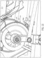
- the rowing engine 20includes a resistance assembly 200 .
- the resistance assembly 200includes at least one resistance mechanism, such as a flywheel with a magnetic brake, a fan, or other suitable resistance mechanism, to resist the pulling action by the user.
- the resistance assembly 200includes two resistance mechanisms, namely a first resistance mechanism 208 , which in this case is a flywheel 210 with a magnetic brake 238 , and a second resistance mechanism 209 , which in this case is a fan 220 .
- the first and second resistance mechanisms 208 , 209are operatively connected to the handles of the rowing machine to resist the pulling action by the user.
- the flywheel 210 and fan 220are rotatably coupled to the frame 100 via the same shaft, output shaft 230 , and thus configured to rotate synchronously about a common rotation axis 202 .
- the flywheel 210 and fan 220are coupled to the frame 100 via the engine support 126 which extends forwardly from the first upright support 112 .
- the rowing engine 20is additionally supported at the front end of the machine 10 by a front stabilizer 116 joined to the engine support 126 .
- the rowing machine 10may use only a flywheel or only a fan, or an entirely different type (e.g., resilience-based) resistance mechanism or any combination thereof in any suitable arrangement to effect the desired resistance to rowing.
- the flywheel 210is rotatably coupled to the frame 100 and operatively associated with a magnetic brake 238 .
- the magnetic brake 238may be implemented as an eddy current brake.
- the flywheel 210may be a disc made from ferromagnetic material and the magnetic brake 238 may include one or more magnets 232 operatively associated with the disc to dissipate the kinetic energy of the rotating disc.
- the one or more magnets 232are movable relative to the flywheel 210 , e.g., along the radial direction 231 , for varying the braking force applied to the flywheel 210 .
- a pair of magnetsare disposed on opposite sides of the flywheel 210 and movable with respect to the flywheel, e.g., by pivotally coupling the magnet mount 234 which supports the magnets 232 to bracket 235 , which is fixed to the frame, to define brake pivot 233 .
- Positioning the magnets closer to the flywheel axisexposes the ferromagnetic disc to a larger amount of resistive force and thus applies a greater amount of braking force and conversely, pivoting the magnets away from the flywheel axis decreases the braking force on the flywheel and thus decreases the resistance to pulling action by the user.
- Any other suitable magnetic brake or a different type of brakemay be used in other examples.
- the rowing machine 10includes at least one handle 413 , and in some embodiments a pair of handles (i.e. left and right handles) operatively connected to the at least one resistance mechanism 208 (e.g., flywheel 210 ) such that rearward movement of the handle is resisted by the at least one resistance mechanism.
- a rowing machine according to the present disclosuremay use a set of rigid links instead of cables to connect the handle to the rowing engine, which may provide certain advantages over cable-based designs. As shown in FIGS.
- the rowing machine 10includes a paddle linkage assembly 400 , in this example including a first (or right) and second (or left) paddle linkages 400 - 1 and 400 - 2 , respectively, that simulate the presence of pair of real paddles or oars and which are thus interchangeably referred to herein as paddles 400 - 1 , 400 - 2 . While the illustrated example shows a paddle linkage assembly 400 including both right and left paddles, it will be understood that in some embodiments, the rowing machine may include only one paddle (i.e. only a right paddle or only a left paddle) such as to simulate sweep rowing.
- FIGS. 7 A and 7 Bwhich show the right paddle 400 - 1 of the machine 10 , components of the paddle linkage assembly 400 will be described. While details are described with reference to the right paddle, it will be understood that the left paddle includes the same components as the right paddle and is a mirror image thereof.
- the paddle linkage assembly 400includes a paddle link 420 , a floating link 440 and a crank link 460 pivotally coupled to one another.
- the pivotal connection between one or more of the links in the paddle linkage 400may be implemented using lug and clevis type joints.
- any other type of suitable pivot jointmay be used to pivotally couple the links, for example by one link being pivotally coupled, via a bearing, to a post extending from the other link (e.g., as in the example in FIGS. 9 - 11 ).
- the paddle link 420 and the crank link 460are pivotally connected to the frame 100 at two spaced apart locations (i.e. pivot A and pivot B), such that the links 420 and 460 , which act as a first and second rocker links, along with the floating link 440 and a fixed virtual link 490 between the two pivots points A and B form a four-bar linkage.
- the two pivot locations A and Bare fixed to the frame.
- the fixed virtual link 490corresponds to the ground link of the four-bar linkage.
- the four-bar linkageis configured as a class II kinematic chain (or a non-Grashof four-bar linkage), which means that no individual link of the four-bar linkage is capable of a full revolution; rather the links are constrained to an oscillating motion.
- oscillating motion of both rockerseliminates the risk of full revolution binding and allows for a more compact design (e.g., a shorter floating link, thus shorter overall length of the machine since the paddle pivot location may be driven by ergonomics for simulating real boat riggings, and the front end of the machine may be thus be driven by the length of the floating link and/or a narrower overall size of the machine).
- a Grashof four-bar linkagewith, for example, the output rocker link configured to revolve fully around the input shaft, may also be used.
- the paddle link 420which is pivotally coupled to the frame at pivot A, is thus configured to pivot about a pivot axis A
- the crank linkwhich is pivotally connected to the frame at pivot B, is configured to pivot about pivot axis B.
- the pivot Ais interchangeably referred to herein as the paddle pivot.
- the location of pivot A and various parameters of one or more of the linksmay be selected so as to mimic the motion of an oar.
- the pivot axis Bis defined by and coincides with the axis of the input shaft 302 .
- the paddle link 420is a rigid member which is pivotally coupled to frame 100 , and in this specific example, to the upright support 114 .
- the paddle link 420includes a tubular member 422 , and first and second end portions 424 , 426 fixed to and extending radially, in two different directions, from the tubular member 422 .
- the first end portion 424extends from one side of the tubular member 422 and is configured for pivotally coupling the handle link thereto.
- the first end portion 424is implemented as a clevis (i.e. a u-shaped or forked connector).
- the second end portion 426extends from an opposite side of the tubular member 422 and is configured as the lug of a clevis and lug type joint between the paddle link 420 and the floating link 440 .
- the second end portion 426defines the input rocker link of the four-bar linkage.
- the first and second end portions 424 , 426extend in different radial directions such that an angle ⁇ is defined therebetween.
- the input rockermay be offset from the nominal paddle axis P in a direction opposite the four-bar linkage by an angle ⁇ , which is less than 90 degrees, and preferably up to about 35 degrees.
- the angle ⁇(and correspondingly angle ⁇ ) remain fixed.
- the offset angle between the floating link 440 and the input rockermay be about 25 degrees from the paddle axis P allowing for a paddle arc sweep of about 115 degrees, which is an accurate representation of the arc sweep during the driving phase of rowing stroke (i.e. from catch to release).
- the input anglei.e. movement of the input rocker by paddle motion driven by the user
- the paddle arc sweepmay be limited to about 115 degrees which may result in approximately 82 degrees of turn at the output rocker.
- the starting position of the paddle arc(e.g., with respect to a horizontal axis 441 ) may be selected such that the catch position more closely mimics real boat rigging.
- the angle of the input rocker with respect to the paddle axismay be selected so as to prevent the output rocker from rotating to and beyond the horizontal position.
- the paddle link 420is pivotable about axis A which coincides with the centerline of the tubular member 422 .
- the tubular member 422is pivotally supported on a post 128 via a bearing.
- the paddle link 420is pivotally connected, at pivot C, to one end of the floating link 440 .
- the opposite end of the floating link 440is pivotally connected, at pivot D, to the crank link 460 , such that when the two rocker links (i.e, paddle link 420 and crank link 460 ) swing back and forth responsive to the sweeping motion by the user on the paddles, the floating link 440 reciprocates back and forth with its first and second ends pivoting about the pivots C and D, respectively.
- the floating link 440is a rigid member pivotally coupled at its opposite ends 442 , 444 to the paddle link 420 and the crank link 460 , respectively, such that the floating link swings back and forth through an arcuate reciprocating motion as the user moves the handles.
- the floating link 440includes, at each of its opposite ends 442 , 444 , a respective connector 443 and 445 , which in this example is implemented as a U-shaped connector or clevis.
- a different arrangement for the pivotal couplingsmay be used, for example by using lug connectors on the floating link and respective clevis connectors on the rocker links, or using a different type of pivotal joint.
- the crank link 460is a rigid member pivotally connected, at its first end 462 , to the floating link 440 , and pivotally connected, at its second end 464 , to the upright support 112 .
- the crank link 460is configured to drive rotation of the input shaft 302 , which is operatively coupled (directly or via one or more intermediate members) to a resistance mechanism (e.g., to flywheel 210 ).
- the first end 462 of the crank link 460is pivotally received in the clevis connector 445 of the floating link and the second end 464 of the crank link 460 includes a collar 466 for coupling the crank link 460 to the input shaft 302 (also referred to as main shaft or drive shaft).
- crank link 460is coupled to the drive shaft such that torque is transmitted from the crank link 460 to the drive shaft 302 in one rotational direction, while allowing the crankshaft 302 to rotate freely in the opposite rotational direction.
- the crank link 460may be coupled to the shaft 302 via a one way (or clutch) bearing 468 provided between the collar 466 and the shaft 302 .
- the handle 413is operatively connected, via the paddle linkage 400 , to the rowing engine 20 such that rearward movement of the handle 413 is resisted by the at least one resistance mechanism (e.g., 208 , 209 ) of the rowing engine 20 .
- a handle link 410connects the handle 413 to the four-bar linkage for providing input to the four-bar linkage.
- the handle link 410is a rigid member (e.g., a tubular member), which may be curved along its length to more accurately mimic a real paddle while allowing for a compact form factor of the rowing machine 10 .
- the handle link 410may include a first end portion 415 which is rigidly connected to and extends along a direction defined by the paddle mount 418 , and a second or handle end portion 412 , which supports the handle 413 and which is curved inward (i.e. toward the centerline of the machine) in relation to the first portion.
- the arrangement of the handle end portion 412may thus resemble the arrangement of the inboard portion of an oar and thus more closely mimic real-life rowing than conventional rowers.
- the handlesmay be coupled to the four bar linkage via a coupling (see also close up view in FIGS. 6 A and 6 B ) that allows the lower end portion of the handle link 410 to pivot about a first axis H to allow motion of the handles toward and away from the center of the machine.
- the couplingallows the handle link 410 , by virtue of its connection to the paddle link 420 , to pivot about a second axis A which allows motion of the handles back and forth, enabling each of the user's hands to traverse independent arcuate paths similar to the path that would be followed if handling real paddles/oars of a boat.
- the couplingmay thus be seen to mimic or function as a universal joint in that it may allowing substantially free and independent movement of each handle with respect to one another and the frame.
- the two pivot axes H and Aare inclined to one another, specifically they are perpendicular to one another. Furthermore, in this example, the two axes H and A do not intersect.
- the first axis Hwhich is defined by the line extending perpendicularly between the two sides of the forked connector 424 , is offset or spaced apart from the pivot axis A, which coincides with the centerline of the tubular member 422 .
- different arrangementsmay be used, such as by inclining the two axes by a different angle with respect to one another or by arranging them so that they intersect.
- the handle link 410is pivotally connected to the paddle link 420 via a paddle mount 418 which provides rotational freedom of the handle link 410 about axis 401 .
- the paddle mount 418is a rigid link formed by two tubular portions in a T-shaped configuration. One of the tubular portions is coupled to the handle link 410 and the other tubular portion is received in the forked connector 424 of the paddle link 420 .
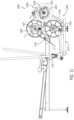
- the rowing engine 20includes a gearing assembly 300 for tailoring the balance between torque and speed.
- the gearing assembly 300is configured to increase the rotational speed of the drive shaft driving the resistance mechanism.
- the gearing assembly 300is configured to gear up by a ratio of up to 1:100 (i.e. an increase in speed from the input shaft 302 to the output shaft 230 by up to 100 times). In some examples a larger gear (or speed) ratio may be used. While referring here to “gearing assembly” and “gear ratio” it will be understood that gearing may be achieved without the use of gears but with other suitable means such as by a belt-drive or chain-drive system using input and output belt-driven discs of different diameters.
- the input and output discsmay be wheels with sprockets such that a chain-driven gearing assembly, rather than a belt-driven assembly, may be used. Any combination of suitable components configured to modify (increase or decrease) the rotational speed between the input and output shafts may be used.
- the rowing enginemay not include a gearing assembly and the power from the user pulling on the handles may be transferred (directly or indirectly) at a 1:1 ratio to the resistance assembly 200 .
- the output link of the paddle linkagemay directly drive the flywheel shaft or the paddle linkage may drive a shaft which is coupled (e.g., via a belt, chain, or gears but without change in the gear ratio) to the flywheel shaft.
- the gearing assembly 300is configured to increase the rotational speed between the input shaft 302 , which is driven by the movement of the paddles, and the output shaft 230 , which drives the resistance assembly (e.g., in this case, both the flywheel and fan, which are rotatable about the same axis R).
- the gearing assembly 300 in this exampleis implemented as a two-stage belt-drive system, which includes a first stage 310 and a second stage 320 .
- the first stage 310includes an input disc 312 , an output disc 314 , and an idler disc 316 , each rotatably supported by the frame, and in this example rotatably coupled to the first upright support 112 via respective shafts.
- the input disc 312is rotatably coupled via the input shaft 302 and the output disc 314 is rotatably coupled via the intermediate output shaft 304 .
- the input disc 312is driven to rotate in a first direction 307 by the forward rocking of the crank link 460 .
- the input disc 312is operatively coupled to the output disc 314 via a suitable power transmission member 318 , in this case a belt 319 .
- the idler disc 316is operatively engaged with the power transmission member 318 to remove slack in the belt 319 .
- the diameter of the input disc 312is larger than the diameter of the output disc 314 thus increasing the rotational speed from input to output of the first stage.
- the second stage 320may be similarly arranged.
- the second stage 320 of gearing assembly 300includes an input disc 322 operatively coupled to an output disc 324 via a second suitable power transmission member 328 (e.g., a belt or a chain), and an idler disc 326 is positioned between the input and output discs 322 , 324 , respectively, to remove slack.
- the input disc 322 of the second stage(interchangeably referred to herein as second input disc) is rotatably supported on the frame by and is thus driven by the rotation of the intermediate output shaft 304 .
- the output disc 324 of the second stage 320(also referred to as second output disc 324 ) is rotatably supported on the frame by the same shaft as the flywheel 210 and fan 220 (see e.g., FIG. 5 ), i.e. output shaft 230 .
- the shafts 302 , 304 and 230 and correspondingly the input discs 312 and 322 and flywheel 210all rotate in the same direction as shown by the arrows 307 , 309 , and 204 .
- the second stage 320also includes a larger input disc as compared to the output disc, thereby further gearing up the rotational speed at the output shaft 230 .
- a different power transmission arrangementmay be used, for example using a single stage or using a different number or arrangement of discs/gears in a given stage.
- each of the input discse.g., first input disc 312 and second input disc 322
- the output discse.g., first output disc 314 and second output disc 324
- the gearing assemblymay be configured to provide a different gear ratio (or speed increase) in other examples, e.g., the speed increase in some examples may be in the range of 80:1 through 120:1.
- the rowing machine 10includes foot rests 119 (i.e., first or right foot rest and second or left foot rest) configured to support the user's feet during use of the machine.
- foot rests 119i.e., first or right foot rest and second or left foot rest
- the user's feetare placed against the foot rests 119 such that the user can push off the foot rests 119 during a rowing stroke (i.e. during the driving phase of the stroke).
- Each of the foot rests 119may be operatively connected to the frame 100 .
- each foot rest 119may be joined to the frame at a fixed angle with respect to ground.
- the foot rests 119may be adjustably connected to the frame to allow the user to change their incline with respect to ground.
- FIGS. 10 - 12show a rowing machine 1010 in accordance with further examples of the present disclosure.
- the rowing machine 1010may include one or more components similar to those described with reference to FIGS. 1 - 9 .
- rowing machine 1010includes a frame 1100 and a rowing engine 1020 .
- the frame 1100includes a base 1110 , which in this example is implemented as a box frame defined by front and rear transverse beams 1111 and 1105 , and first and second longitudinal beams 1107 and 1109 .
- the frame 1100also includes a front support 1112 fixed to and extending upward (in this case perpendicularly to) the front transverse beam 1111 and a rear support 1114 fixed to and extending upward from the rear transverse beam 1105 .
- a rail support 1124is connected to both the front and rear supports 1112 and 1114 and supports the rail 1115 which is configured to slidably support the seat 1117 such that the seat 1117 can move back and forth along the rail 1115 .
- the seat 1117may be removably coupled to the seat rail 1115 .
- the seat rail 1115is pivotally coupled to the rail support (e.g., at pivot 1125 ) such that the incline of the rail 1115 with respect to the base and thus with respect to ground could be adjusted.
- the engine 1020includes a resistance assembly 1200 and a transmission assembly 1300 .
- the resistance assembly 1200includes a magnetically resisted rotating disc 1210 and a fan 1220 , both of which are rotatably supported on the same shaft 1230 .
- the rotation of the shaft 1230is resisted by a magnetic eddy current brake 1238 which applies a magnetic resistive force on the rotating disc 1210 to resist the rotation of the shaft 1230 .
- the fan 1220which includes a plurality of paddles 1222 provided between inner and outer discs 1223 and 1225 , respectively, also resist the rotation of the shaft 1230 independently of the resistance by the magnetic brake 1238 .
- the fan 1220is coupled to the shaft 1230 via a one-way bearing such that the fan 1220 can continue to spin when there is no user input, thus allowing for the inertia of the fan to provide a feeling to the user as if gliding through water and also to allow the “catch” point of the rowing stroke to be felt at all resistances.
- the resistance assembly 1200is supported on an engine support 1126 , which is connected to and extends between the front support 1112 and a front stabilizer 1116 .
- the transmission assemblyis implemented as a two-stage belt-drive assembly including a first stage 1310 and a second stage 1320 .
- Each stageincludes an input and an output member operatively connected to one another to change the rotational speed from input to output.
- the first and second stagesare operatively connected to achieve an overall or combined change in the rotational speed.
- the output member of the first stagemay rotate on the same shaft as the input member of the second stage thus the output shaft of the first stage 1310 drives the input member of the second stage.
- a different arrangementmay be used such as by using another belt or chain or one or more gears to transmit the rotation of the output shaft of the first stage to the input of the second stage.
- the rowing machine 1010utilizes a plurality of rigid links, rather than cables and pulleys, to connect the handles to the rowing engine 1020 for transferring the power from the user thereto.
- the relationships between the seat 1117 , paddle pivots, the catch position, and feet anglesare selected to mimic boat rigging setups to maximize similarities to a real boat.
- the paddle pivotsmay be arranged at a location aft of the foot rests which may provide a boat compatible location during row (in recovery and initial pull).
- the rowing machinemay include at least one measurement apparatus operatively associated with one or more moving components of the rowing machine (e.g., the crank shaft, the flywheel shaft, or both, or with any of the links) so as to monitor the movement (e.g., rotation) thereof.
- the movemente.g., rotation
- paddle locationsmay be monitored throughout the entire stroke, which can allow for the visualization of the user's action/muscle activation and/or for coaching of rowing technique.
- monitoring of motionmay be achieved via magnetic potentiometers 502 operatively arranged (e.g., on each of the left and right sides) with respect to the main shaft, as shown for example in FIG. 12 .
- the resistance disc and/or fan rotationsmay be monitored using a reed switch 504 and a magnet 506 to measure power.
- a reed switch 504may be disposed on the flywheel 210 at a radial position such that when the flywheel rotates, the magnet 506 will pass within a close enough proximity of a reed switch 504 to cause, by magnetic force an electrical contact or other sensor in the reed switch to close, thereby signaling a revolution of the flywheel.
- Other types and arrangements of measurement devicesmay be used.
- Hall effect, inductive, capacitive, photoelectric, mechanical, and/or ultrasonic sensorscan be used in place of, or in addition to, a magnet 506 and a reed switch 504 .
- sensorscan also be disposed on or in relation to the input disc 312 , the input disc 322 , the output disc 314 , and/or the output disc 324 .
- the resistance disk shaft 230may be equipped with optical sensors 508 a , 508 b .
- the optical sensors 508 a , 508 bcan each have a light emitter disposed on one side of the resistance disc 210 , and a detector disposed on the other side of the resistance disc, opposite the emitter, such that the detector can detect the presence or absence of light emitted by the emitter.
- the resistance disc 210can be a notched disk (see e.g., FIG. 13 ), or be operatively coupled with such a notched disk, the notched disk having a plurality of sensor flags 212 with gaps 214 disposed between the flags 212 .
- the flags 212 and gaps 214can be arranged such that as the resistance disc 210 spins, the flags 212 and gaps alternately block and pass light emitted from the emitter of the optical sensors 508 a , 508 b to the respective detectors in the optical sensors 580 a , 580 b .
- the optical sensors 508 a , 508 bcan measure the rotational speed of the resistance disc 210 . Using two or more sensors, the direction of the disc 210 can be monitored as well.
- one sensor 508 a , 508 bmonitors clockwise rotation and the other sensor 508 a , 508 b monitors counter clockwise rotation, which can then be used to calculate parameters of the movement of the paddles (e.g., direction of paddles).
- FIG. 14shows a partial view of another rowing machine according to the present disclosure.
- the rowing machine in FIG. 14includes a rowing engine located at the front end of the machine and a linkage assembly connecting the handles to the rowing engine.
- the linkage assemblyincludes two sets of links, each simulating one of the left and right paddles of a boat.
- Each set of linksis configured as a four-bar linkage including an input rocker and an output rocker (each approximately 100 mm in length, in this example), a floating link (of approximately 460 mm, in this example) and a ground link (of approximately 440 mm, in this example).
- Inputis provided to the four-bar linkage via a corresponding paddle which is mounted to the input rocker such that the paddle is movable back and forth and toward and away from center during use of the machine.
- a transmission assemblywhich includes a chain-driven first transmission stage 310 and a belt-driven second transmission stage 320 .
- the two fundamental reference points in the anatomy of a rowing strokeare the catch where the oar blade is placed in the water and the extraction (also known as the finish) where the oar blade is removed from the water.
- the rowerapplies pressure to the oar levering the boat forward which is called the drive phase of the stroke.
- the recovery phasebegins, setting up the rowers body for the next stroke.
- gearingsimilar to bicycle gearing, is used to adjust the power needed to operate the oars or paddles. Light or low gears provide an easy exertion level—that is, one stroke of the paddle is easy to do, requires less power, but does not take the user far.
- FIG. 15illustrates variables or parameters relevant to boat rigging.
- a rowing machinemay be configured with a stretcher angle 606 within the range of 35-50 degrees, and more preferably within the range of 40-44 degrees.
- a stretcher angle 606 on the high endmay be used to allow as much power from the push off while maintaining near vertical shins at catch for a wide demographic of users.
- the rowing machinemay be configured for a heel depth 604 in the range of 12-22 cm, or more preferably in the range of 15-19 cm.
- a heel depth 604 of 17 cmmay be used in some examples, as the near neutral position for neither high nor low geared boats.
- a stretcher position 600 within the range of 50-69 cm or preferably in the range of 55-65 cmmay be used.
- a shorter than average stretcher position 600e.g., around 50 cm
- the stretcher position 600may also affect the overall side of the machine, thus a shorter stretcher position 600 may provide a more compact design.
- a suitable range for the work through 602 for embodiments hereinmay be anywhere within the range of 12-22 cm or preferably within the range of 14-20 cm.
- a work through 602 on the higher endmay be selected to allow for taller users to utilize the rowing machine and/or to provide a heavier gearing feel, or the work through 602 value may be adjusted toward the lower end to achieve the opposite result.
- Other relevant parameters to boat riggingcan include the gate height 608 above the seat 612 , and the position of the center line of the pin 610 .
- Other configuration parameters of the rowing machine that may affect the gearing feeling of the rowing machinemay include the seat rail angle, which as previously discussed, may be configured to be at an incline and/or adjustable to an incline of at least up to 6 degrees to provide for a stronger workout thus mimicking higher gearing.
- the paddle pivotsmay be positioned close to the centerline of the seat when in the catch position thus more closely mimicking the loading on the body in real-life rowing/boating.
Landscapes
- Health & Medical Sciences (AREA)
- Physical Education & Sports Medicine (AREA)
- General Health & Medical Sciences (AREA)
- Vascular Medicine (AREA)
- Cardiology (AREA)
- Orthopedic Medicine & Surgery (AREA)
- Biophysics (AREA)
- Life Sciences & Earth Sciences (AREA)
- Physics & Mathematics (AREA)
- Electromagnetism (AREA)
- Transmission Devices (AREA)
- Rehabilitation Tools (AREA)
- Soil Working Implements (AREA)
Abstract
Description
Claims (19)
Priority Applications (2)
| Application Number | Priority Date | Filing Date | Title |
|---|---|---|---|
| US17/328,954US11724152B2 (en) | 2018-07-20 | 2021-05-24 | Stationary exercise machine with four-bar linkage transmission |
| US18/345,491US20230390600A1 (en) | 2018-07-20 | 2023-06-30 | Stationary exercise machine with four-bar linkage transmission |
Applications Claiming Priority (3)
| Application Number | Priority Date | Filing Date | Title |
|---|---|---|---|
| US201862701391P | 2018-07-20 | 2018-07-20 | |
| US16/517,415US11013952B2 (en) | 2018-07-20 | 2019-07-19 | Rowing machine |
| US17/328,954US11724152B2 (en) | 2018-07-20 | 2021-05-24 | Stationary exercise machine with four-bar linkage transmission |
Related Parent Applications (1)
| Application Number | Title | Priority Date | Filing Date |
|---|---|---|---|
| US16/517,415ContinuationUS11013952B2 (en) | 2018-07-20 | 2019-07-19 | Rowing machine |
Related Child Applications (1)
| Application Number | Title | Priority Date | Filing Date |
|---|---|---|---|
| US18/345,491ContinuationUS20230390600A1 (en) | 2018-07-20 | 2023-06-30 | Stationary exercise machine with four-bar linkage transmission |
Publications (2)
| Publication Number | Publication Date |
|---|---|
| US20210275859A1 US20210275859A1 (en) | 2021-09-09 |
| US11724152B2true US11724152B2 (en) | 2023-08-15 |
Family
ID=67539616
Family Applications (3)
| Application Number | Title | Priority Date | Filing Date |
|---|---|---|---|
| US16/517,415ActiveUS11013952B2 (en) | 2018-07-20 | 2019-07-19 | Rowing machine |
| US17/328,954Active2039-07-29US11724152B2 (en) | 2018-07-20 | 2021-05-24 | Stationary exercise machine with four-bar linkage transmission |
| US18/345,491PendingUS20230390600A1 (en) | 2018-07-20 | 2023-06-30 | Stationary exercise machine with four-bar linkage transmission |
Family Applications Before (1)
| Application Number | Title | Priority Date | Filing Date |
|---|---|---|---|
| US16/517,415ActiveUS11013952B2 (en) | 2018-07-20 | 2019-07-19 | Rowing machine |
Family Applications After (1)
| Application Number | Title | Priority Date | Filing Date |
|---|---|---|---|
| US18/345,491PendingUS20230390600A1 (en) | 2018-07-20 | 2023-06-30 | Stationary exercise machine with four-bar linkage transmission |
Country Status (4)
| Country | Link |
|---|---|
| US (3) | US11013952B2 (en) |
| EP (1) | EP3823732A2 (en) |
| CN (1) | CN112703042B (en) |
| WO (1) | WO2020018955A2 (en) |
Cited By (1)
| Publication number | Priority date | Publication date | Assignee | Title |
|---|---|---|---|---|
| US20230390600A1 (en)* | 2018-07-20 | 2023-12-07 | Nautilus, Inc. | Stationary exercise machine with four-bar linkage transmission |
Families Citing this family (12)
| Publication number | Priority date | Publication date | Assignee | Title |
|---|---|---|---|---|
| US11813497B2 (en)* | 2020-09-23 | 2023-11-14 | Christopher Anthony Gatta | Parallel resistance rowing machine |
| USD944339S1 (en)* | 2021-01-22 | 2022-02-22 | Sailvan Times Co., Ltd. | Rowing machine |
| CN113230582B (en)* | 2021-04-22 | 2022-06-10 | 浙江力玄运动科技股份有限公司 | Water resistance rowing machine |
| US12357893B2 (en) | 2021-04-26 | 2025-07-15 | Brian J. Chisholm | Dynamic rowing machine |
| US11759667B2 (en)* | 2021-08-23 | 2023-09-19 | Yen-Chao LIN | Reciprocating unidirectional electromagnetic resistance device |
| DE102021134578A1 (en)* | 2021-12-23 | 2023-06-29 | Augletics Gmbh | Training device and method for simulating a rowing movement |
| CN114082133B (en)* | 2021-12-28 | 2024-12-20 | 厦门市德比健康科技有限公司 | A double resistance system water resistance type rowing machine |
| US12017107B2 (en)* | 2021-12-29 | 2024-06-25 | Hydrow, Inc. | Exercise machine brake system |
| CN116617626A (en)* | 2022-02-11 | 2023-08-22 | 甲尚实业股份有限公司 | Resistance Devices and Resistance Training Machines |
| KR102610310B1 (en)* | 2023-06-08 | 2023-12-06 | (주)뉴텍웰니스 | Two-way Row Machine |
| USD1013805S1 (en)* | 2023-11-07 | 2024-02-06 | Dongbo Lu | Seated row machine |
| USD1023181S1 (en)* | 2023-12-11 | 2024-04-16 | Zhiqiong Gu | Tricep dip press machine |
Citations (168)
| Publication number | Priority date | Publication date | Assignee | Title |
|---|---|---|---|---|
| GB1101009A (en) | 1965-05-28 | 1968-01-31 | Petros Elia | Improvements in and relating to physical training equipment |
| US3898950A (en) | 1974-02-12 | 1975-08-12 | Arthur E Martin | Rowing apparatus |
| WO1980002647A1 (en) | 1979-06-04 | 1980-12-11 | Inventec Licensing Bv | Exercising equipment |
| US4284272A (en) | 1978-02-10 | 1981-08-18 | Tekron Licensing B.V. | Exercise machines |
| US4346886A (en) | 1979-06-04 | 1982-08-31 | Black & Decker Inc. | Variable resistance exercising device |
| US4396188A (en) | 1981-07-15 | 1983-08-02 | Dreissigacker Peter D | Stationary rowing unit |
| US4477071A (en) | 1982-05-25 | 1984-10-16 | Bodytone Limited | Convertible rowing exercising apparatus |
| US4541627A (en) | 1983-07-29 | 1985-09-17 | Maclean W Douglas | Exercise rowing machine |
| US4563000A (en) | 1984-10-26 | 1986-01-07 | Sears, Roebuck And Co. | Rowing apparatus |
| US4572500A (en) | 1984-07-23 | 1986-02-25 | Eugene Weiss | Rowing exercise device |
| USD286311S (en) | 1984-05-25 | 1986-10-21 | Pro Form, Inc. | Rowing machine |
| DE3625159A1 (en) | 1985-08-09 | 1987-02-19 | Tmc Corp | Rowing training apparatus |
| US4647035A (en) | 1984-07-16 | 1987-03-03 | Robert Yellen | Rowing exercise device |
| US4650181A (en) | 1986-01-21 | 1987-03-17 | Yang Tzu Tsan | Dynamic rowing machine |
| US4674741A (en) | 1985-08-05 | 1987-06-23 | Bally Manufacturing Corporation | Rowing machine with video display |
| WO1987004358A1 (en) | 1986-01-15 | 1987-07-30 | Diversified Products Corporation | Kayak exerciser device |
| US4690398A (en) | 1986-02-10 | 1987-09-01 | Smith Robert S | Multipurpose rowing apparatus |
| US4695050A (en) | 1985-09-16 | 1987-09-22 | Precor Incorporated | Exercise rowing machine |
| US4705493A (en) | 1986-09-08 | 1987-11-10 | Shinn Fu Corporation | Transmission mechanism for gymnastic bicycle |
| US4714244A (en) | 1986-04-04 | 1987-12-22 | Bally Manufacturing Corporation | Rowing machine with improved mechanical features |
| US4722520A (en) | 1984-07-13 | 1988-02-02 | Lee Wen Kuei | Rowing exercise machine |
| US4723774A (en) | 1984-03-07 | 1988-02-09 | Maquina Sports, S.A. | Exercise machine |
| US4735410A (en) | 1986-08-13 | 1988-04-05 | Mizuno Corporation | Rowing machine |
| US4736944A (en) | 1986-10-09 | 1988-04-12 | M & R Industries, Inc. | Exercise rowing machine frame structure |
| US4743010A (en) | 1986-08-11 | 1988-05-10 | Alexander Geraci | Dynamic powered rowing machine |
| US4743011A (en)* | 1986-07-07 | 1988-05-10 | Calvin Coffey | Exercise rowing machine |
| US4746112A (en)* | 1986-10-02 | 1988-05-24 | Fayal James E | Exercise rowing machine |
| US4756523A (en)* | 1986-07-03 | 1988-07-12 | M & R Industries, Inc. | Exercise rowing machine with seat carriage lock |
| US4768776A (en)* | 1987-03-30 | 1988-09-06 | Anthony Giannotti | Rowing exercise machine extension |
| US4768775A (en)* | 1987-07-13 | 1988-09-06 | Frank E. Marshall | Combination rowing machine and chest exerciser |
| US4772013A (en)* | 1985-12-09 | 1988-09-20 | Tarlow Jr Elliot S | Rowing exercise machine |
| US4795147A (en)* | 1986-01-15 | 1989-01-03 | Diversified Products Corporation | Convertible exercise device |
| US4798378A (en)* | 1985-07-15 | 1989-01-17 | Jones Robert S | Rowing machine |
| US4813667A (en) | 1986-05-08 | 1989-03-21 | Weslo, Inc. | Multipurpose exerciser |
| US4822032A (en)* | 1987-04-23 | 1989-04-18 | Whitmore Henry B | Exercise machine |
| US4846460A (en)* | 1987-05-13 | 1989-07-11 | Duke John H | Rowing machine |
| US4867447A (en)* | 1986-10-09 | 1989-09-19 | Avita Health And Fitness Products Inc. | System for determining performance on an exercise rowing machine |
| US4880224A (en)* | 1988-10-19 | 1989-11-14 | Werner Jonas | Rowing machine |
| US4883268A (en) | 1989-04-12 | 1989-11-28 | Mccabe-White Investment Corporation | Compact, portable, rowing type exercise apparatus usable by a chair-seated exerciser |
| US4884800A (en) | 1987-05-13 | 1989-12-05 | Duke John H | Rowing machine |
| US4921242A (en) | 1988-07-20 | 1990-05-01 | Weslo, Inc. | Exercise apparatus resistance system |
| US4930769A (en) | 1986-12-08 | 1990-06-05 | Nenoff Joseph R | Unified pull-push exercise device |
| US4943051A (en) | 1986-05-27 | 1990-07-24 | Don Haskins | Human energy transmission device |
| DE3943391A1 (en) | 1989-01-31 | 1990-08-02 | Tunturipyoerae Oy | RUDDER ARRANGEMENT |
| WO1990014132A1 (en) | 1989-05-17 | 1990-11-29 | Harold Ronald Evans | Rowing exercise machine |
| US4974832A (en) | 1990-02-16 | 1990-12-04 | Proform Fitness Products, Inc. | Rower slant board |
| US4976423A (en) | 1986-07-25 | 1990-12-11 | Jorma Routti | Rowing device |
| US4997181A (en) | 1989-02-21 | 1991-03-05 | Lo Peter K | Wind-drag type exercise rowing unit |
| US5013033A (en) | 1989-02-01 | 1991-05-07 | Proform Fitness Products, Inc. | Rowing apparatus |
| US5072929A (en) | 1990-06-13 | 1991-12-17 | Nordictrack, Inc. | Dual resistance exercise rowing machine |
| US5092581A (en) | 1990-07-02 | 1992-03-03 | Michael Koz | Rowing exercise apparatus |
| US5094446A (en) | 1990-09-06 | 1992-03-10 | Wiedner Joseph F | Rowing exercise machine |
| US5104363A (en) | 1991-09-17 | 1992-04-14 | James Shi | Hydraulic resistance type stationary rowing unit |
| US5108093A (en) | 1986-05-08 | 1992-04-28 | Weslo, Inc. | Multipurpose exerciser |
| US5122105A (en) | 1990-08-31 | 1992-06-16 | Nordictrack, Inc. | Seat for an exercise apparatus |
| USD337799S (en) | 1991-07-25 | 1993-07-27 | Nordictrack, Inc. | Exercise rowing machine |
| US5295931A (en) | 1992-09-04 | 1994-03-22 | Nordictrack, Inc. | Rowing machine exercise apparatus |
| USD352534S (en) | 1992-08-26 | 1994-11-15 | Nordictrack, Inc. | Rowing machine exerciser |
| US5370593A (en) | 1994-02-01 | 1994-12-06 | Greenmaster Industrial Corp. | Bevel seated rowing machine |
| US5382210A (en) | 1992-11-13 | 1995-01-17 | Rekers; Casper J. N. | Dynamically balanced rowing simulator |
| US5441469A (en) | 1995-01-12 | 1995-08-15 | Chern; Minghwa | Exercise machine for realistic simulation of boat rowing |
| USD367508S (en) | 1994-02-28 | 1996-02-27 | Concept Ii, Inc. | Rowing machine |
| US5569130A (en) | 1995-09-08 | 1996-10-29 | Greenmaster Industrial Corp. | Rowing machine |
| US5616105A (en) | 1996-01-29 | 1997-04-01 | Greenmaster Industrial Corp. | Rowing machine |
| WO1997022389A1 (en) | 1995-12-19 | 1997-06-26 | Leslie Pape | Rowing simulator |
| US5645514A (en) | 1996-09-20 | 1997-07-08 | Chen; Paul | Pulling type exerciser |
| US5658225A (en) | 1995-12-14 | 1997-08-19 | Chan-Nan Liu | Structure of rowing machine |
| US5707322A (en) | 1994-02-28 | 1998-01-13 | Concept Ii, Inc. | Exercise machine |
| US5865713A (en) | 1997-05-23 | 1999-02-02 | Hsu; Hank | Multipurpose exercise device |
| GB2327621A (en) | 1997-07-24 | 1999-02-03 | Greenmaster Ind Corp | Rowing machine with magnetic resistance mechanism |
| US5899780A (en) | 1996-04-12 | 1999-05-04 | Robbins; Gerald Mark | Rowing apparatus |
| US5916069A (en) | 1997-03-12 | 1999-06-29 | Wang; Leao | Rowing exerciser with magnetic resistance |
| US6071215A (en) | 1997-04-26 | 2000-06-06 | Raffo; David M. | Multi-mode exercise machine |
| WO2000076592A1 (en) | 1999-06-10 | 2000-12-21 | Concept Ii, Inc. | Machine-assisted exercising |
| US6168554B1 (en) | 1997-12-23 | 2001-01-02 | Steve W. Berg | Exercise attachment for cross country ski simulator |
| US6206808B1 (en) | 1999-09-15 | 2001-03-27 | Sung-Chao Ho | Angle-adjustable rowing exerciser |
| US6231485B1 (en) | 1994-02-28 | 2001-05-15 | Concept Ii, Inc. | Exercise machine |
| US20020022558A1 (en)* | 1999-09-15 | 2002-02-21 | Michael Casey | Angle-adjustable rowing exerciser |
| US20020115537A1 (en)* | 2001-02-19 | 2002-08-22 | Richard Lin | Rowing exercise machine |
| US6527680B1 (en) | 1995-09-28 | 2003-03-04 | Joseph D. Maresh | Six bar exercise machine |
| GB2380331A (en) | 2001-10-01 | 2003-04-02 | Exertris Ltd | Eddy current load unit for an exercise machine |
| US6565489B2 (en) | 1999-09-15 | 2003-05-20 | Sung-Cho Ho | Angled-adjustable rowing exerciser |
| US6602168B2 (en) | 2000-03-08 | 2003-08-05 | John H. Duke | Flexion extension exerciser |
| US20030166438A1 (en)* | 2002-03-01 | 2003-09-04 | Federico Gramaccioni | Swinging implement for simulating rowing exercises |
| US6682462B1 (en) | 2003-02-21 | 2004-01-27 | Sunny Lee | Dual-purpose exerciser operable in pedaling and rowing modes |
| US6749546B2 (en) | 2002-08-27 | 2004-06-15 | Lien-Chaun Yang | Structure of an exercising apparatus as a rowboat |
| WO2005025685A1 (en) | 2003-09-15 | 2005-03-24 | Matthew Duncan Roach | Rowing simulation machine |
| US20050130810A1 (en)* | 2003-12-02 | 2005-06-16 | Lenny Sands | Multi-purpose exercise device |
| US6926647B1 (en) | 2003-06-02 | 2005-08-09 | Johnson Kuo | Folding collapsible rowing machine |
| US6960156B2 (en) | 2002-05-16 | 2005-11-01 | Paul Smith | Device for directing air flow at users of air resisted exercise machines |
| US20050272568A1 (en)* | 2004-06-07 | 2005-12-08 | Leao Wang | Folding mechanism for a rowing device |
| US20050277521A1 (en)* | 2004-06-09 | 2005-12-15 | Shu-Chtung Lat | Rowing exercising apparatus |
| US6981932B1 (en) | 2003-09-10 | 2006-01-03 | Johnson Kuo | Rowing machine |
| US20060009334A1 (en) | 2004-07-09 | 2006-01-12 | Smith Jeffrey A | Rowing device with a lifting device |
| US6991589B1 (en) | 2000-08-09 | 2006-01-31 | Paul Patterson | Multi-planar rowing machine and associated exercise protocols |
| US7022052B1 (en) | 2003-04-14 | 2006-04-04 | Fen-Ying Lai | Collapsible boat rowing stimulator |
| US20060100069A1 (en)* | 2004-10-12 | 2006-05-11 | Nautilus, Inc. | Exercise device |
| US7108639B2 (en) | 2004-07-09 | 2006-09-19 | Fitcrew Corp. | Adjustable rowing machine |
| US7115077B2 (en) | 2005-02-09 | 2006-10-03 | Lien-Chuan Yang | Exercise rowing machine |
| US20060264128A1 (en)* | 2005-05-23 | 2006-11-23 | Osten Frederick F | Portable rowing/exercise device |
| US7141008B2 (en) | 2004-02-24 | 2006-11-28 | Krull Mark A | Rowing machine with elliptical seat motion |
| US20060270528A1 (en)* | 2005-05-25 | 2006-11-30 | Fen-Ying Lai | Rowing exercise apparatus |
| US20070049470A1 (en)* | 2005-08-29 | 2007-03-01 | Johnson Health Tech Co., Ltd. | Rapid circuit training machine with dual resistance |
| US20070082793A1 (en)* | 2005-10-11 | 2007-04-12 | Lien-Chuan Yang | Exercise rowboat with a fan |
| US7204790B2 (en) | 2001-03-13 | 2007-04-17 | Robert H. Sleamaker | Multi-sport training machine with inclined monorail and roller carriage |
| US7226397B1 (en) | 2004-07-20 | 2007-06-05 | Brunswick Corporation | Rowing exercise machine |
| US7229388B2 (en) | 2005-10-11 | 2007-06-12 | Lien-Chuan Yang | Exercise rowing machine |
| US20070191189A1 (en)* | 2006-02-10 | 2007-08-16 | Iviva International Corp. | Foldable step exerciser |
| US7270630B1 (en) | 2001-01-29 | 2007-09-18 | Paul Patterson | Rowing machine having a flex handle assembly for preferentially enabling an extended range of motion for selected joint complexes |
| US7361124B1 (en) | 2007-01-26 | 2008-04-22 | Tseng Chung-Ting | Rowing machine |
| US20080261782A1 (en)* | 2007-01-23 | 2008-10-23 | Mark Campbell | Rowing Machine Simulators |
| WO2008137841A1 (en) | 2007-05-04 | 2008-11-13 | Medina Rafael R | Bilaterally actuated sculling trainer |
| US7500938B2 (en) | 2006-02-16 | 2009-03-10 | Hsin Lung Accessories Co., Ltd. | Rowing exercise device |
| WO2009097452A1 (en) | 2008-01-29 | 2009-08-06 | Row Balance Inc. | Adjustable lateral instability feature for rowing simulator |
| US7585263B2 (en) | 2005-01-05 | 2009-09-08 | Ab Coasler Holdings, Inc. | Abdominal exercise machine |
| US20100009816A1 (en)* | 2008-07-11 | 2010-01-14 | Robert Edmondson | Articulated handles for rowing exercise devices |
| US7708670B2 (en) | 2004-02-21 | 2010-05-04 | Vq Actioncare, Llc | Seated row exercise system |
| US7731637B2 (en) | 2007-05-11 | 2010-06-08 | D Eredita Michael | Simulated rowing machine |
| US7766802B2 (en) | 2003-08-04 | 2010-08-03 | Hoist Fitness Systems, Inc. | Rowing exercise machine with self-aligning pivoting user support |
| CN201603338U (en) | 2010-02-09 | 2010-10-13 | 曾俊明 | Rowing machine |
| US7833136B2 (en)* | 2008-01-12 | 2010-11-16 | Bell Edward J | Rowing trainer |
| US7846074B2 (en)* | 2008-10-31 | 2010-12-07 | Strength Master Fitness Tech. Co., Ltd. | Recumbent exerciser |
| US7862484B1 (en)* | 2009-11-03 | 2011-01-04 | Coffey Calvin T | Folding exercise rowing machine |
| US20110028278A1 (en)* | 2009-06-09 | 2011-02-03 | Roach Matthew D | Dynamic Rowing Machine |
| US20110065554A1 (en) | 2009-09-14 | 2011-03-17 | Willem Johannes Van Straaten | Exercise machine |
| US20110082015A1 (en)* | 2009-10-02 | 2011-04-07 | Concept Ii, Inc. | Exercising |
| US8070657B2 (en) | 2006-02-28 | 2011-12-06 | Andrew Robert Loach | Exercise machine |
| CN202185108U (en) | 2011-07-21 | 2012-04-11 | 厦门宙隆运动器材有限公司 | Novel rowing machine |
| US20120100965A1 (en)* | 2010-10-22 | 2012-04-26 | Dick Dreissigacker | Exercising |
| US8192332B2 (en) | 2009-01-23 | 2012-06-05 | Blackstone Automation, LLC | Energy absorbing suspension equipment (EASE) for rowing machines |
| US20120225753A1 (en) | 2009-07-10 | 2012-09-06 | Sns Care Co., Ltd. | Rowing Machine Exercise-Assisting Device |
| WO2013006145A1 (en) | 2011-07-04 | 2013-01-10 | Univerza V Ljubljani | System for training rowing technique |
| EP2545965A2 (en) | 2011-07-12 | 2013-01-16 | Christopher Smith | Rowing simulator and training aid |
| US20130296137A1 (en) | 2011-01-21 | 2013-11-07 | Shenzhen Antuoshan Special Machine & Electrical Co., Ltd. | Exercise rowing machine with power generation |
| US8608626B2 (en)* | 2007-01-23 | 2013-12-17 | Rowperfect Pty Ltd | Rowing machine simulator |
| US8622876B2 (en) | 2010-04-01 | 2014-01-07 | Rowing Innovations Inc. | Rowing simulator |
| WO2014054931A1 (en) | 2012-10-02 | 2014-04-10 | Uab "Abili" | Unstable rowing simulator |
| US20140141941A1 (en)* | 2012-11-21 | 2014-05-22 | Cybex International, Inc. | Rowing machine |
| US8771151B2 (en) | 2011-01-31 | 2014-07-08 | Lars Larsson | Adjustable exercise apparatus simulating a kayak |
| US8795210B2 (en)* | 2006-07-11 | 2014-08-05 | American Medical Innovations, L.L.C. | System and method for a low profile vibrating plate |
| US20140243163A1 (en) | 2013-02-26 | 2014-08-28 | Robert Edmondson | Gravity return rowing exercise device |
| US20140336011A1 (en)* | 2013-05-07 | 2014-11-13 | Basix International Inc. | Rowing simulator |
| WO2014196870A1 (en) | 2013-06-04 | 2014-12-11 | Ziad Badarneh | An apparatus for physical rowing exercise |
| US8944969B2 (en) | 2002-03-04 | 2015-02-03 | Cybex International, Inc. | Rowing machine |
| US9005086B1 (en) | 2013-08-28 | 2015-04-14 | Douglas L. Hermann | Portable rowing machine |
| WO2015054618A1 (en) | 2013-10-10 | 2015-04-16 | Actervis Gmbh | Body transformer |
| US9028374B1 (en) | 2013-02-05 | 2015-05-12 | Scott P. Brady | Rowing exercise device |
| US20160001123A1 (en) | 2014-07-01 | 2016-01-07 | Anthony Roberts Parrish, JR. | Rowing machine suspension device |
| US9272180B2 (en)* | 2013-11-19 | 2016-03-01 | Paul William Eschenbach | Rowing stepper exercise apparatus |
| US20160059069A1 (en) | 2014-09-03 | 2016-03-03 | Bojan R. Jeremic | Electronically controlled mechanical resistance device for rowing machines |
| US20160144223A1 (en) | 2014-11-26 | 2016-05-26 | Icon Health & Fitness, Inc. | Rowing Machine Having a Beam with a Hinge Joint |
| CN205494791U (en) | 2016-02-02 | 2016-08-24 | 刘总兵 | Hydromagnetic hinders body -building machine of rowing boat |
| US20160287933A1 (en)* | 2015-04-06 | 2016-10-06 | Fu-Hai Lin | Compounded fitness trainer |
| US20160375297A1 (en) | 2015-06-23 | 2016-12-29 | Contrast Optical Design & Engineering, Inc. | Adaptor for an indoor rowing machine |
| US20170043208A1 (en) | 2015-08-10 | 2017-02-16 | Larry Ellsworth Lonergan | Transportable Rowing Unit |
| CN106730595A (en) | 2017-04-07 | 2017-05-31 | 中山生动力健身器材有限公司 | Body-building rowing machine |
| ES1187316U (en) | 2016-06-21 | 2017-07-11 | Gabriel Orlando FRACAROLI JUAREZ | Rowing training apparatus (Machine-translation by Google Translate, not legally binding) |
| CN206372491U (en) | 2016-12-20 | 2017-08-04 | 厦门奥力龙科技有限公司 | New-type drawing rowing machine |
| US9750972B1 (en) | 2016-04-11 | 2017-09-05 | Dyaco International Inc. | Folding mechanism of rowing machine |
| US9770622B2 (en) | 2014-10-21 | 2017-09-26 | Total Gym Global Corp | Rowing exercise device and method of using same |
| US20170319889A1 (en) | 2016-05-05 | 2017-11-09 | Technogym S.P.A. | Rowing machine |
| US20180056117A1 (en)* | 2015-03-13 | 2018-03-01 | Anthony Carl Hamilton | Rowing machine |
| CN207384713U (en) | 2017-11-06 | 2018-05-22 | 马伟军 | Rowing machine |
| CN207605300U (en) | 2017-01-12 | 2018-07-13 | 临沂市凯莱特健身器材有限公司 | A kind of combined liquid resistance magnetic resistance rowing machine of resistance-adjustable |
| US10449409B2 (en)* | 2016-11-04 | 2019-10-22 | Nautilus, Inc. | Stowable rowing machine |
| US20200023232A1 (en) | 2018-07-20 | 2020-01-23 | Nautilus, Inc. | Rowing machine |
| US11298584B2 (en)* | 2017-06-12 | 2022-04-12 | Biorower Handelsagentur Gmbh | Training apparatus |
| US20220177303A1 (en)* | 2019-05-08 | 2022-06-09 | 3M Innovative Properties Company | Nanostructured article |
Family Cites Families (4)
| Publication number | Priority date | Publication date | Assignee | Title |
|---|---|---|---|---|
| CH189669A (en)* | 1936-02-15 | 1937-03-15 | Aubert Julien | Body exercise apparatus for performing rowing movements. |
| FR2643821B3 (en)* | 1989-03-01 | 1991-05-17 | Moreno Gilbert | ROWER-TYPE MUSCLE EXERCISE APPARATUS |
| US5470295A (en) | 1995-03-07 | 1995-11-28 | Wang; Chin-Liu | Rowing exercise machine |
| ITFI20110188A1 (en)* | 2011-08-30 | 2013-03-01 | Giorgio Benvenuti | "VOGA SIMULATION SYSTEM" |
- 2019
- 2019-07-19USUS16/517,415patent/US11013952B2/enactiveActive
- 2019-07-19EPEP19749520.3Apatent/EP3823732A2/ennot_activeWithdrawn
- 2019-07-19WOPCT/US2019/042682patent/WO2020018955A2/ennot_activeCeased
- 2019-07-19CNCN201980059018.XApatent/CN112703042B/enactiveActive
- 2021
- 2021-05-24USUS17/328,954patent/US11724152B2/enactiveActive
- 2023
- 2023-06-30USUS18/345,491patent/US20230390600A1/enactivePending
Patent Citations (192)
| Publication number | Priority date | Publication date | Assignee | Title |
|---|---|---|---|---|
| GB1101009A (en) | 1965-05-28 | 1968-01-31 | Petros Elia | Improvements in and relating to physical training equipment |
| US3898950A (en) | 1974-02-12 | 1975-08-12 | Arthur E Martin | Rowing apparatus |
| US4284272A (en) | 1978-02-10 | 1981-08-18 | Tekron Licensing B.V. | Exercise machines |
| US4346886A (en) | 1979-06-04 | 1982-08-31 | Black & Decker Inc. | Variable resistance exercising device |
| US4421307A (en) | 1979-06-04 | 1983-12-20 | Tekron Licensing Bv | Folding exercising equipment |
| WO1980002647A1 (en) | 1979-06-04 | 1980-12-11 | Inventec Licensing Bv | Exercising equipment |
| US4396188A (en) | 1981-07-15 | 1983-08-02 | Dreissigacker Peter D | Stationary rowing unit |
| US4477071A (en) | 1982-05-25 | 1984-10-16 | Bodytone Limited | Convertible rowing exercising apparatus |
| US4541627A (en) | 1983-07-29 | 1985-09-17 | Maclean W Douglas | Exercise rowing machine |
| US4723774A (en) | 1984-03-07 | 1988-02-09 | Maquina Sports, S.A. | Exercise machine |
| USD286311S (en) | 1984-05-25 | 1986-10-21 | Pro Form, Inc. | Rowing machine |
| US4722520A (en) | 1984-07-13 | 1988-02-02 | Lee Wen Kuei | Rowing exercise machine |
| US4647035A (en) | 1984-07-16 | 1987-03-03 | Robert Yellen | Rowing exercise device |
| US4572500A (en) | 1984-07-23 | 1986-02-25 | Eugene Weiss | Rowing exercise device |
| US4563000A (en) | 1984-10-26 | 1986-01-07 | Sears, Roebuck And Co. | Rowing apparatus |
| US4798378A (en)* | 1985-07-15 | 1989-01-17 | Jones Robert S | Rowing machine |
| US4674741A (en) | 1985-08-05 | 1987-06-23 | Bally Manufacturing Corporation | Rowing machine with video display |
| DE3625159A1 (en) | 1985-08-09 | 1987-02-19 | Tmc Corp | Rowing training apparatus |
| US4695050A (en) | 1985-09-16 | 1987-09-22 | Precor Incorporated | Exercise rowing machine |
| US4772013A (en)* | 1985-12-09 | 1988-09-20 | Tarlow Jr Elliot S | Rowing exercise machine |
| WO1987004358A1 (en) | 1986-01-15 | 1987-07-30 | Diversified Products Corporation | Kayak exerciser device |
| US4795147A (en)* | 1986-01-15 | 1989-01-03 | Diversified Products Corporation | Convertible exercise device |
| US4650181A (en) | 1986-01-21 | 1987-03-17 | Yang Tzu Tsan | Dynamic rowing machine |
| US4690398A (en) | 1986-02-10 | 1987-09-01 | Smith Robert S | Multipurpose rowing apparatus |
| US4714244A (en) | 1986-04-04 | 1987-12-22 | Bally Manufacturing Corporation | Rowing machine with improved mechanical features |
| US5108093A (en) | 1986-05-08 | 1992-04-28 | Weslo, Inc. | Multipurpose exerciser |
| US4813667A (en) | 1986-05-08 | 1989-03-21 | Weslo, Inc. | Multipurpose exerciser |
| US4943051A (en) | 1986-05-27 | 1990-07-24 | Don Haskins | Human energy transmission device |
| US4756523A (en)* | 1986-07-03 | 1988-07-12 | M & R Industries, Inc. | Exercise rowing machine with seat carriage lock |
| US4743011A (en)* | 1986-07-07 | 1988-05-10 | Calvin Coffey | Exercise rowing machine |
| US4976423A (en) | 1986-07-25 | 1990-12-11 | Jorma Routti | Rowing device |
| US4743010A (en) | 1986-08-11 | 1988-05-10 | Alexander Geraci | Dynamic powered rowing machine |
| US4735410A (en) | 1986-08-13 | 1988-04-05 | Mizuno Corporation | Rowing machine |
| US4705493A (en) | 1986-09-08 | 1987-11-10 | Shinn Fu Corporation | Transmission mechanism for gymnastic bicycle |
| US4746112A (en)* | 1986-10-02 | 1988-05-24 | Fayal James E | Exercise rowing machine |
| US4867447A (en)* | 1986-10-09 | 1989-09-19 | Avita Health And Fitness Products Inc. | System for determining performance on an exercise rowing machine |
| US4736944A (en) | 1986-10-09 | 1988-04-12 | M & R Industries, Inc. | Exercise rowing machine frame structure |
| US4930769A (en) | 1986-12-08 | 1990-06-05 | Nenoff Joseph R | Unified pull-push exercise device |
| US4768776A (en)* | 1987-03-30 | 1988-09-06 | Anthony Giannotti | Rowing exercise machine extension |
| US4822032A (en)* | 1987-04-23 | 1989-04-18 | Whitmore Henry B | Exercise machine |
| US4846460A (en)* | 1987-05-13 | 1989-07-11 | Duke John H | Rowing machine |
| US4884800A (en) | 1987-05-13 | 1989-12-05 | Duke John H | Rowing machine |
| US4768775A (en)* | 1987-07-13 | 1988-09-06 | Frank E. Marshall | Combination rowing machine and chest exerciser |
| US4921242A (en) | 1988-07-20 | 1990-05-01 | Weslo, Inc. | Exercise apparatus resistance system |
| US4880224A (en)* | 1988-10-19 | 1989-11-14 | Werner Jonas | Rowing machine |
| DE3943391A1 (en) | 1989-01-31 | 1990-08-02 | Tunturipyoerae Oy | RUDDER ARRANGEMENT |
| US5013033A (en) | 1989-02-01 | 1991-05-07 | Proform Fitness Products, Inc. | Rowing apparatus |
| US4997181A (en) | 1989-02-21 | 1991-03-05 | Lo Peter K | Wind-drag type exercise rowing unit |
| US4883268A (en) | 1989-04-12 | 1989-11-28 | Mccabe-White Investment Corporation | Compact, portable, rowing type exercise apparatus usable by a chair-seated exerciser |
| WO1990014132A1 (en) | 1989-05-17 | 1990-11-29 | Harold Ronald Evans | Rowing exercise machine |
| US4974832A (en) | 1990-02-16 | 1990-12-04 | Proform Fitness Products, Inc. | Rower slant board |
| US5072929A (en) | 1990-06-13 | 1991-12-17 | Nordictrack, Inc. | Dual resistance exercise rowing machine |
| US5092581A (en) | 1990-07-02 | 1992-03-03 | Michael Koz | Rowing exercise apparatus |
| US5122105A (en) | 1990-08-31 | 1992-06-16 | Nordictrack, Inc. | Seat for an exercise apparatus |
| US5094446A (en) | 1990-09-06 | 1992-03-10 | Wiedner Joseph F | Rowing exercise machine |
| USD337799S (en) | 1991-07-25 | 1993-07-27 | Nordictrack, Inc. | Exercise rowing machine |
| US5104363A (en) | 1991-09-17 | 1992-04-14 | James Shi | Hydraulic resistance type stationary rowing unit |
| USD352534S (en) | 1992-08-26 | 1994-11-15 | Nordictrack, Inc. | Rowing machine exerciser |
| US5295931A (en) | 1992-09-04 | 1994-03-22 | Nordictrack, Inc. | Rowing machine exercise apparatus |
| US5382210A (en) | 1992-11-13 | 1995-01-17 | Rekers; Casper J. N. | Dynamically balanced rowing simulator |
| US5370593A (en) | 1994-02-01 | 1994-12-06 | Greenmaster Industrial Corp. | Bevel seated rowing machine |
| USD367508S (en) | 1994-02-28 | 1996-02-27 | Concept Ii, Inc. | Rowing machine |
| US6231485B1 (en) | 1994-02-28 | 2001-05-15 | Concept Ii, Inc. | Exercise machine |
| US6371892B1 (en) | 1994-02-28 | 2002-04-16 | Concept Ii, Inc. | Exercise machine |
| US5707322A (en) | 1994-02-28 | 1998-01-13 | Concept Ii, Inc. | Exercise machine |
| US5441469A (en) | 1995-01-12 | 1995-08-15 | Chern; Minghwa | Exercise machine for realistic simulation of boat rowing |
| US5569130A (en) | 1995-09-08 | 1996-10-29 | Greenmaster Industrial Corp. | Rowing machine |
| US6527680B1 (en) | 1995-09-28 | 2003-03-04 | Joseph D. Maresh | Six bar exercise machine |
| US5658225A (en) | 1995-12-14 | 1997-08-19 | Chan-Nan Liu | Structure of rowing machine |
| WO1997022389A1 (en) | 1995-12-19 | 1997-06-26 | Leslie Pape | Rowing simulator |
| US5779600A (en)* | 1995-12-19 | 1998-07-14 | Pape; Leslie | Rowing simulator |
| US5616105A (en) | 1996-01-29 | 1997-04-01 | Greenmaster Industrial Corp. | Rowing machine |
| US5899780A (en) | 1996-04-12 | 1999-05-04 | Robbins; Gerald Mark | Rowing apparatus |
| US5645514A (en) | 1996-09-20 | 1997-07-08 | Chen; Paul | Pulling type exerciser |
| US5916069A (en) | 1997-03-12 | 1999-06-29 | Wang; Leao | Rowing exerciser with magnetic resistance |
| US6071215A (en) | 1997-04-26 | 2000-06-06 | Raffo; David M. | Multi-mode exercise machine |
| US5865713A (en) | 1997-05-23 | 1999-02-02 | Hsu; Hank | Multipurpose exercise device |
| GB2327621A (en) | 1997-07-24 | 1999-02-03 | Greenmaster Ind Corp | Rowing machine with magnetic resistance mechanism |
| US6168554B1 (en) | 1997-12-23 | 2001-01-02 | Steve W. Berg | Exercise attachment for cross country ski simulator |
| US7201708B2 (en) | 1999-06-10 | 2007-04-10 | Concept Ii, Inc. | Machine-assisted exercising |
| WO2000076592A1 (en) | 1999-06-10 | 2000-12-21 | Concept Ii, Inc. | Machine-assisted exercising |
| US20010008861A1 (en)* | 1999-06-10 | 2001-07-19 | Concept Ii, Inc., Vermont Corporation | Machine-assisted exercising |
| US6561955B1 (en) | 1999-06-10 | 2003-05-13 | Concept Ii, Inc. | Machine-assisted exercising |
| US20020022558A1 (en)* | 1999-09-15 | 2002-02-21 | Michael Casey | Angle-adjustable rowing exerciser |
| US6206808B1 (en) | 1999-09-15 | 2001-03-27 | Sung-Chao Ho | Angle-adjustable rowing exerciser |
| US6565489B2 (en) | 1999-09-15 | 2003-05-20 | Sung-Cho Ho | Angled-adjustable rowing exerciser |
| US6695753B2 (en) | 1999-09-15 | 2004-02-24 | Michael Casey | Handle-assisted exerciser |
| US6602168B2 (en) | 2000-03-08 | 2003-08-05 | John H. Duke | Flexion extension exerciser |
| US6991589B1 (en) | 2000-08-09 | 2006-01-31 | Paul Patterson | Multi-planar rowing machine and associated exercise protocols |
| US7270630B1 (en) | 2001-01-29 | 2007-09-18 | Paul Patterson | Rowing machine having a flex handle assembly for preferentially enabling an extended range of motion for selected joint complexes |
| US20020115537A1 (en)* | 2001-02-19 | 2002-08-22 | Richard Lin | Rowing exercise machine |
| US7204790B2 (en) | 2001-03-13 | 2007-04-17 | Robert H. Sleamaker | Multi-sport training machine with inclined monorail and roller carriage |
| GB2380331A (en) | 2001-10-01 | 2003-04-02 | Exertris Ltd | Eddy current load unit for an exercise machine |
| US20050101450A1 (en) | 2002-03-01 | 2005-05-12 | Federico Gramaccioni | Swinging implement for simulating rowing exercises |
| US20030166438A1 (en)* | 2002-03-01 | 2003-09-04 | Federico Gramaccioni | Swinging implement for simulating rowing exercises |
| US8944969B2 (en) | 2002-03-04 | 2015-02-03 | Cybex International, Inc. | Rowing machine |
| US6960156B2 (en) | 2002-05-16 | 2005-11-01 | Paul Smith | Device for directing air flow at users of air resisted exercise machines |
| US6749546B2 (en) | 2002-08-27 | 2004-06-15 | Lien-Chaun Yang | Structure of an exercising apparatus as a rowboat |
| US6682462B1 (en) | 2003-02-21 | 2004-01-27 | Sunny Lee | Dual-purpose exerciser operable in pedaling and rowing modes |
| US7022052B1 (en) | 2003-04-14 | 2006-04-04 | Fen-Ying Lai | Collapsible boat rowing stimulator |
| US6926647B1 (en) | 2003-06-02 | 2005-08-09 | Johnson Kuo | Folding collapsible rowing machine |
| US7766802B2 (en) | 2003-08-04 | 2010-08-03 | Hoist Fitness Systems, Inc. | Rowing exercise machine with self-aligning pivoting user support |
| US6981932B1 (en) | 2003-09-10 | 2006-01-03 | Johnson Kuo | Rowing machine |
| US7572211B2 (en) | 2003-09-15 | 2009-08-11 | Matthew Duncan Roach | Rowing simulation machine |
| WO2005025685A1 (en) | 2003-09-15 | 2005-03-24 | Matthew Duncan Roach | Rowing simulation machine |
| US20050130810A1 (en)* | 2003-12-02 | 2005-06-16 | Lenny Sands | Multi-purpose exercise device |
| US7988601B2 (en) | 2004-02-21 | 2011-08-02 | Vq Actioncare, Llc | Seated row exercise system |
| US7708670B2 (en) | 2004-02-21 | 2010-05-04 | Vq Actioncare, Llc | Seated row exercise system |
| US7141008B2 (en) | 2004-02-24 | 2006-11-28 | Krull Mark A | Rowing machine with elliptical seat motion |
| US20050272568A1 (en)* | 2004-06-07 | 2005-12-08 | Leao Wang | Folding mechanism for a rowing device |
| US20050277521A1 (en)* | 2004-06-09 | 2005-12-15 | Shu-Chtung Lat | Rowing exercising apparatus |
| US20060009334A1 (en) | 2004-07-09 | 2006-01-12 | Smith Jeffrey A | Rowing device with a lifting device |
| US7381164B2 (en) | 2004-07-09 | 2008-06-03 | Fitcrew Corp. | Rowing device with a lifting device |
| US7108639B2 (en) | 2004-07-09 | 2006-09-19 | Fitcrew Corp. | Adjustable rowing machine |
| US7226397B1 (en) | 2004-07-20 | 2007-06-05 | Brunswick Corporation | Rowing exercise machine |
| US7815552B2 (en) | 2004-10-12 | 2010-10-19 | Nautilus, Inc. | Exercise device |
| US20060116249A1 (en) | 2004-10-12 | 2006-06-01 | Nautilus, Inc. | Exercise device |
| US20060100069A1 (en)* | 2004-10-12 | 2006-05-11 | Nautilus, Inc. | Exercise device |
| US7585263B2 (en) | 2005-01-05 | 2009-09-08 | Ab Coasler Holdings, Inc. | Abdominal exercise machine |
| US7115077B2 (en) | 2005-02-09 | 2006-10-03 | Lien-Chuan Yang | Exercise rowing machine |
| US20060264128A1 (en)* | 2005-05-23 | 2006-11-23 | Osten Frederick F | Portable rowing/exercise device |
| US20060270528A1 (en)* | 2005-05-25 | 2006-11-30 | Fen-Ying Lai | Rowing exercise apparatus |
| US20070049470A1 (en)* | 2005-08-29 | 2007-03-01 | Johnson Health Tech Co., Ltd. | Rapid circuit training machine with dual resistance |
| US7229388B2 (en) | 2005-10-11 | 2007-06-12 | Lien-Chuan Yang | Exercise rowing machine |
| US20070082793A1 (en)* | 2005-10-11 | 2007-04-12 | Lien-Chuan Yang | Exercise rowboat with a fan |
| US20070191189A1 (en)* | 2006-02-10 | 2007-08-16 | Iviva International Corp. | Foldable step exerciser |
| US7500938B2 (en) | 2006-02-16 | 2009-03-10 | Hsin Lung Accessories Co., Ltd. | Rowing exercise device |
| US20120065034A1 (en) | 2006-02-28 | 2012-03-15 | Andrew Robert Loach | Exercise machine |
| US8070657B2 (en) | 2006-02-28 | 2011-12-06 | Andrew Robert Loach | Exercise machine |
| US8795210B2 (en)* | 2006-07-11 | 2014-08-05 | American Medical Innovations, L.L.C. | System and method for a low profile vibrating plate |
| US20080261782A1 (en)* | 2007-01-23 | 2008-10-23 | Mark Campbell | Rowing Machine Simulators |
| US8608626B2 (en)* | 2007-01-23 | 2013-12-17 | Rowperfect Pty Ltd | Rowing machine simulator |
| US7361124B1 (en) | 2007-01-26 | 2008-04-22 | Tseng Chung-Ting | Rowing machine |
| WO2008137841A1 (en) | 2007-05-04 | 2008-11-13 | Medina Rafael R | Bilaterally actuated sculling trainer |
| US7731637B2 (en) | 2007-05-11 | 2010-06-08 | D Eredita Michael | Simulated rowing machine |
| US8235874B2 (en) | 2007-05-11 | 2012-08-07 | D Eredita Michael | Simulated rowing machine |
| US7833136B2 (en)* | 2008-01-12 | 2010-11-16 | Bell Edward J | Rowing trainer |
| US7946964B2 (en) | 2008-01-29 | 2011-05-24 | Gothro Anne G | Adjustable lateral instability feature for rowing simulator |
| WO2009097452A1 (en) | 2008-01-29 | 2009-08-06 | Row Balance Inc. | Adjustable lateral instability feature for rowing simulator |
| US8038582B2 (en) | 2008-07-11 | 2011-10-18 | Robert Edmondson | Articulated handles for rowing exercise devices |
| US20100009816A1 (en)* | 2008-07-11 | 2010-01-14 | Robert Edmondson | Articulated handles for rowing exercise devices |
| US7846074B2 (en)* | 2008-10-31 | 2010-12-07 | Strength Master Fitness Tech. Co., Ltd. | Recumbent exerciser |
| US8192332B2 (en) | 2009-01-23 | 2012-06-05 | Blackstone Automation, LLC | Energy absorbing suspension equipment (EASE) for rowing machines |
| US20110028278A1 (en)* | 2009-06-09 | 2011-02-03 | Roach Matthew D | Dynamic Rowing Machine |
| US20120225753A1 (en) | 2009-07-10 | 2012-09-06 | Sns Care Co., Ltd. | Rowing Machine Exercise-Assisting Device |
| US20110065554A1 (en) | 2009-09-14 | 2011-03-17 | Willem Johannes Van Straaten | Exercise machine |
| US20110082015A1 (en)* | 2009-10-02 | 2011-04-07 | Concept Ii, Inc. | Exercising |
| WO2011056210A1 (en) | 2009-11-03 | 2011-05-12 | Calvin T Coffey | Folding exercise rowing machine |
| US7862484B1 (en)* | 2009-11-03 | 2011-01-04 | Coffey Calvin T | Folding exercise rowing machine |
| CN201603338U (en) | 2010-02-09 | 2010-10-13 | 曾俊明 | Rowing machine |
| US8622876B2 (en) | 2010-04-01 | 2014-01-07 | Rowing Innovations Inc. | Rowing simulator |
| US20120100965A1 (en)* | 2010-10-22 | 2012-04-26 | Dick Dreissigacker | Exercising |
| US20130296137A1 (en) | 2011-01-21 | 2013-11-07 | Shenzhen Antuoshan Special Machine & Electrical Co., Ltd. | Exercise rowing machine with power generation |
| US8771151B2 (en) | 2011-01-31 | 2014-07-08 | Lars Larsson | Adjustable exercise apparatus simulating a kayak |
| WO2013006145A1 (en) | 2011-07-04 | 2013-01-10 | Univerza V Ljubljani | System for training rowing technique |
| US20130130206A1 (en)* | 2011-07-12 | 2013-05-23 | Christopher McGuirk Smith | Rowing Simulator and Training Aid |
| EP2545965A2 (en) | 2011-07-12 | 2013-01-16 | Christopher Smith | Rowing simulator and training aid |
| CN202185108U (en) | 2011-07-21 | 2012-04-11 | 厦门宙隆运动器材有限公司 | Novel rowing machine |
| WO2014054931A1 (en) | 2012-10-02 | 2014-04-10 | Uab "Abili" | Unstable rowing simulator |
| US20150258366A1 (en) | 2012-10-02 | 2015-09-17 | Uab "Abili" | Unstable rowing simulator |
| US20140141941A1 (en)* | 2012-11-21 | 2014-05-22 | Cybex International, Inc. | Rowing machine |
| US9028374B1 (en) | 2013-02-05 | 2015-05-12 | Scott P. Brady | Rowing exercise device |
| US20140243163A1 (en) | 2013-02-26 | 2014-08-28 | Robert Edmondson | Gravity return rowing exercise device |
| US20140336011A1 (en)* | 2013-05-07 | 2014-11-13 | Basix International Inc. | Rowing simulator |
| WO2014179866A1 (en) | 2013-05-07 | 2014-11-13 | Basix International Inc. | Rowing simulator |
| WO2014196870A1 (en) | 2013-06-04 | 2014-12-11 | Ziad Badarneh | An apparatus for physical rowing exercise |
| US9005086B1 (en) | 2013-08-28 | 2015-04-14 | Douglas L. Hermann | Portable rowing machine |
| WO2015054618A1 (en) | 2013-10-10 | 2015-04-16 | Actervis Gmbh | Body transformer |
| US20150202484A1 (en) | 2013-10-10 | 2015-07-23 | Actervis Gmbh | Body transformer |
| US9272180B2 (en)* | 2013-11-19 | 2016-03-01 | Paul William Eschenbach | Rowing stepper exercise apparatus |
| US20160001123A1 (en) | 2014-07-01 | 2016-01-07 | Anthony Roberts Parrish, JR. | Rowing machine suspension device |
| US20160059069A1 (en) | 2014-09-03 | 2016-03-03 | Bojan R. Jeremic | Electronically controlled mechanical resistance device for rowing machines |
| US9770622B2 (en) | 2014-10-21 | 2017-09-26 | Total Gym Global Corp | Rowing exercise device and method of using same |
| US20160144223A1 (en) | 2014-11-26 | 2016-05-26 | Icon Health & Fitness, Inc. | Rowing Machine Having a Beam with a Hinge Joint |
| US20180056117A1 (en)* | 2015-03-13 | 2018-03-01 | Anthony Carl Hamilton | Rowing machine |
| US20160287933A1 (en)* | 2015-04-06 | 2016-10-06 | Fu-Hai Lin | Compounded fitness trainer |
| US20160375297A1 (en) | 2015-06-23 | 2016-12-29 | Contrast Optical Design & Engineering, Inc. | Adaptor for an indoor rowing machine |
| US20170043208A1 (en) | 2015-08-10 | 2017-02-16 | Larry Ellsworth Lonergan | Transportable Rowing Unit |
| CN205494791U (en) | 2016-02-02 | 2016-08-24 | 刘总兵 | Hydromagnetic hinders body -building machine of rowing boat |
| US9750972B1 (en) | 2016-04-11 | 2017-09-05 | Dyaco International Inc. | Folding mechanism of rowing machine |
| US10376730B2 (en)* | 2016-05-05 | 2019-08-13 | Technogym S.P.A. | Rowing machine |
| US20170319889A1 (en) | 2016-05-05 | 2017-11-09 | Technogym S.P.A. | Rowing machine |
| ES1187316U (en) | 2016-06-21 | 2017-07-11 | Gabriel Orlando FRACAROLI JUAREZ | Rowing training apparatus (Machine-translation by Google Translate, not legally binding) |
| US10449409B2 (en)* | 2016-11-04 | 2019-10-22 | Nautilus, Inc. | Stowable rowing machine |
| CN206372491U (en) | 2016-12-20 | 2017-08-04 | 厦门奥力龙科技有限公司 | New-type drawing rowing machine |
| CN207605300U (en) | 2017-01-12 | 2018-07-13 | 临沂市凯莱特健身器材有限公司 | A kind of combined liquid resistance magnetic resistance rowing machine of resistance-adjustable |
| CN106730595A (en) | 2017-04-07 | 2017-05-31 | 中山生动力健身器材有限公司 | Body-building rowing machine |
| US11298584B2 (en)* | 2017-06-12 | 2022-04-12 | Biorower Handelsagentur Gmbh | Training apparatus |
| CN207384713U (en) | 2017-11-06 | 2018-05-22 | 马伟军 | Rowing machine |
| US20200023232A1 (en) | 2018-07-20 | 2020-01-23 | Nautilus, Inc. | Rowing machine |
| US11013952B2 (en)* | 2018-07-20 | 2021-05-25 | Nautilus, Inc. | Rowing machine |
| US20220177303A1 (en)* | 2019-05-08 | 2022-06-09 | 3M Innovative Properties Company | Nanostructured article |
Non-Patent Citations (3)
| Title |
|---|
| "Translation for Second Office Action for CN 201980059018.X, dated Apr. 19, 2022". |
| English translation of First Office Action for CN Appl. No. 201980059018.X dated Oct. 11, 2021. |
| International Search Report and Written Opinion for PCT/US2019/042682 dated Jan. 31, 2020. |
Cited By (1)
| Publication number | Priority date | Publication date | Assignee | Title |
|---|---|---|---|---|
| US20230390600A1 (en)* | 2018-07-20 | 2023-12-07 | Nautilus, Inc. | Stationary exercise machine with four-bar linkage transmission |
Also Published As
| Publication number | Publication date |
|---|---|
| CN112703042B (en) | 2022-11-22 |
| CN112703042A (en) | 2021-04-23 |
| US20200023232A1 (en) | 2020-01-23 |
| EP3823732A2 (en) | 2021-05-26 |
| WO2020018955A2 (en) | 2020-01-23 |
| US20230390600A1 (en) | 2023-12-07 |
| WO2020018955A3 (en) | 2020-03-05 |
| US11013952B2 (en) | 2021-05-25 |
| US20210275859A1 (en) | 2021-09-09 |
Similar Documents
| Publication | Publication Date | Title |
|---|---|---|
| US11724152B2 (en) | Stationary exercise machine with four-bar linkage transmission | |
| CN111182947B (en) | fitness equipment | |
| US5836855A (en) | Recumbent elliptical exercise machine | |
| US9050498B2 (en) | Exercise assemblies having foot pedal members that are movable along user defined paths | |
| US5779600A (en) | Rowing simulator | |
| US9138614B2 (en) | Exercise assemblies having linear motion synchronizing mechanism | |
| US6932745B1 (en) | Seated stepper | |
| US9114275B2 (en) | Exercise assemblies having crank members with limited rotation | |
| US5707321A (en) | Four bar exercise machine | |
| US7033306B2 (en) | Spontaneous symmetrical weight shifting device | |
| US7833136B2 (en) | Rowing trainer | |
| CN110382057B (en) | Stationary exercise machine with power measuring device | |
| CN100418599C (en) | Practice device that simulates skating movements | |
| US7591762B2 (en) | Exercise apparatus | |
| CA2056019C (en) | Rowing exercise apparatus | |
| US7601102B2 (en) | Gymnastic machine | |
| US6017295A (en) | Recumbent mobile exercise apparatus | |
| CA2851120C (en) | Rowing simulator | |
| SE467997B (en) | CYCLE eXERCISER | |
| US11298584B2 (en) | Training apparatus | |
| US7780580B2 (en) | Arm exercise apparatus for run simulation | |
| RU2092208C1 (en) | Rower training apparatus | |
| CN111936211B (en) | sports training machine | |
| TW200810805A (en) | Equipment for reciprocating exercise of legs |
Legal Events
| Date | Code | Title | Description |
|---|---|---|---|
| AS | Assignment | Owner name:NAUTILUS, INC., WASHINGTON Free format text:ASSIGNMENT OF ASSIGNORS INTEREST;ASSIGNORS:FRENCH, EDANA;TEDSEN, KIRK;HAMILTON, BRYAN W.;SIGNING DATES FROM 20190628 TO 20190701;REEL/FRAME:056334/0488 | |
| FEPP | Fee payment procedure | Free format text:ENTITY STATUS SET TO UNDISCOUNTED (ORIGINAL EVENT CODE: BIG.); ENTITY STATUS OF PATENT OWNER: SMALL ENTITY | |
| FEPP | Fee payment procedure | Free format text:ENTITY STATUS SET TO SMALL (ORIGINAL EVENT CODE: SMAL); ENTITY STATUS OF PATENT OWNER: SMALL ENTITY | |
| STPP | Information on status: patent application and granting procedure in general | Free format text:DOCKETED NEW CASE - READY FOR EXAMINATION | |
| STPP | Information on status: patent application and granting procedure in general | Free format text:NON FINAL ACTION MAILED | |
| AS | Assignment | Owner name:CRYSTAL FINANCIAL LLC D/B/A SLR CREDIT SOLUTIONS, MASSACHUSETTS Free format text:SECURITY INTEREST;ASSIGNOR:NAUTILUS, INC.;REEL/FRAME:062029/0373 Effective date:20221130 | |
| AS | Assignment | Owner name:NAUTILUS, INC., WASHINGTON Free format text:SECURITY INTEREST;ASSIGNOR:WELLS FARGO BANK, NATIONAL ASSOCIATION;REEL/FRAME:062038/0027 Effective date:20221130 | |
| FEPP | Fee payment procedure | Free format text:ENTITY STATUS SET TO UNDISCOUNTED (ORIGINAL EVENT CODE: BIG.); ENTITY STATUS OF PATENT OWNER: SMALL ENTITY | |
| FEPP | Fee payment procedure | Free format text:ENTITY STATUS SET TO SMALL (ORIGINAL EVENT CODE: SMAL); ENTITY STATUS OF PATENT OWNER: SMALL ENTITY | |
| STPP | Information on status: patent application and granting procedure in general | Free format text:PUBLICATIONS -- ISSUE FEE PAYMENT VERIFIED | |
| STCF | Information on status: patent grant | Free format text:PATENTED CASE | |
| AS | Assignment | Owner name:BOWFLEX INC., WASHINGTON Free format text:CHANGE OF NAME;ASSIGNOR:NAUTILUS, INC.;REEL/FRAME:065808/0931 Effective date:20231020 | |
| AS | Assignment | Owner name:CRYSTAL FINANCIAL LLC D/B/A SLR CREDIT SOLUTIONS, MASSACHUSETTS Free format text:SECURITY INTEREST;ASSIGNOR:BOWFLEX INC.;REEL/FRAME:066369/0555 Effective date:20240124 | |
| AS | Assignment | Owner name:WELLS FARGO BANK, NATIONAL ASSOCIATION, ILLINOIS Free format text:PATENT SECURITY AGREEMENT;ASSIGNOR:BOWFLEX INC.;REEL/FRAME:066374/0281 Effective date:20240124 | |
| AS | Assignment | Owner name:BOWFLEX INC. (F/K/A NAUTILUS, INC.), WASHINGTON Free format text:RELEASE BY SECURED PARTY;ASSIGNOR:WELLS FARGO BANK, NATIONAL ASSOCIATION;REEL/FRAME:066726/0001 Effective date:20240226 Owner name:BOWFLEX INC. (F/K/A NAUTILUS, INC.), WASHINGTON Free format text:RELEASE BY SECURED PARTY;ASSIGNOR:WELLS FARGO BANK, NATIONAL ASSOCIATION;REEL/FRAME:066725/0904 Effective date:20240226 | |
| AS | Assignment | Owner name:BOWFLEX INC., WASHINGTON Free format text:RELEASE BY SECURED PARTY;ASSIGNOR:CRYSTAL FINANCIAL LLC (D/B/A SLR CREDIT SOLUTIONS);REEL/FRAME:067239/0001 Effective date:20240422 Owner name:BOWFLEX INC., WASHINGTON Free format text:RELEASE BY SECURED PARTY;ASSIGNOR:CRYSTAL FINANCIAL LLC (D/B/A SLR CREDIT SOLUTIONS);REEL/FRAME:067239/0121 Effective date:20240422 | |
| AS | Assignment | Owner name:JOHNSON HEALTH TECH RETAIL, INC., WISCONSIN Free format text:ASSIGNMENT OF ASSIGNORS INTEREST;ASSIGNOR:BOWFLEX INC.;REEL/FRAME:067807/0675 Effective date:20240422 |