US11724116B2 - Wearable cardioverter defibrillator latching connector - Google Patents
Wearable cardioverter defibrillator latching connectorDownload PDFInfo
- Publication number
- US11724116B2 US11724116B2US16/994,525US202016994525AUS11724116B2US 11724116 B2US11724116 B2US 11724116B2US 202016994525 AUS202016994525 AUS 202016994525AUS 11724116 B2US11724116 B2US 11724116B2
- Authority
- US
- United States
- Prior art keywords
- wcd
- connector
- receptacle
- signals
- shield
- Prior art date
- Legal status (The legal status is an assumption and is not a legal conclusion. Google has not performed a legal analysis and makes no representation as to the accuracy of the status listed.)
- Active, expires
Links
Images


Classifications
- A—HUMAN NECESSITIES
- A61—MEDICAL OR VETERINARY SCIENCE; HYGIENE
- A61N—ELECTROTHERAPY; MAGNETOTHERAPY; RADIATION THERAPY; ULTRASOUND THERAPY
- A61N1/00—Electrotherapy; Circuits therefor
- A61N1/18—Applying electric currents by contact electrodes
- A61N1/32—Applying electric currents by contact electrodes alternating or intermittent currents
- A61N1/38—Applying electric currents by contact electrodes alternating or intermittent currents for producing shock effects
- A61N1/39—Heart defibrillators
- A61N1/3904—External heart defibrillators [EHD]
- A—HUMAN NECESSITIES
- A61—MEDICAL OR VETERINARY SCIENCE; HYGIENE
- A61N—ELECTROTHERAPY; MAGNETOTHERAPY; RADIATION THERAPY; ULTRASOUND THERAPY
- A61N1/00—Electrotherapy; Circuits therefor
- A61N1/18—Applying electric currents by contact electrodes
- A61N1/32—Applying electric currents by contact electrodes alternating or intermittent currents
- A61N1/36—Applying electric currents by contact electrodes alternating or intermittent currents for stimulation
- A61N1/36014—External stimulators, e.g. with patch electrodes
- A61N1/3603—Control systems
- A—HUMAN NECESSITIES
- A61—MEDICAL OR VETERINARY SCIENCE; HYGIENE
- A61N—ELECTROTHERAPY; MAGNETOTHERAPY; RADIATION THERAPY; ULTRASOUND THERAPY
- A61N1/00—Electrotherapy; Circuits therefor
- A61N1/18—Applying electric currents by contact electrodes
- A61N1/32—Applying electric currents by contact electrodes alternating or intermittent currents
- A61N1/36—Applying electric currents by contact electrodes alternating or intermittent currents for stimulation
- A61N1/372—Arrangements in connection with the implantation of stimulators
- A61N1/375—Constructional arrangements, e.g. casings
- A61N1/3752—Details of casing-lead connections
- A—HUMAN NECESSITIES
- A61—MEDICAL OR VETERINARY SCIENCE; HYGIENE
- A61N—ELECTROTHERAPY; MAGNETOTHERAPY; RADIATION THERAPY; ULTRASOUND THERAPY
- A61N1/00—Electrotherapy; Circuits therefor
- A61N1/18—Applying electric currents by contact electrodes
- A61N1/32—Applying electric currents by contact electrodes alternating or intermittent currents
- A61N1/36—Applying electric currents by contact electrodes alternating or intermittent currents for stimulation
- A61N1/372—Arrangements in connection with the implantation of stimulators
- A61N1/375—Constructional arrangements, e.g. casings
- A61N1/3758—Packaging of the components within the casing
- A—HUMAN NECESSITIES
- A61—MEDICAL OR VETERINARY SCIENCE; HYGIENE
- A61N—ELECTROTHERAPY; MAGNETOTHERAPY; RADIATION THERAPY; ULTRASOUND THERAPY
- A61N1/00—Electrotherapy; Circuits therefor
- A61N1/18—Applying electric currents by contact electrodes
- A61N1/32—Applying electric currents by contact electrodes alternating or intermittent currents
- A61N1/38—Applying electric currents by contact electrodes alternating or intermittent currents for producing shock effects
- A61N1/39—Heart defibrillators
- A61N1/3925—Monitoring; Protecting
- A61N1/3937—Monitoring output parameters
- A—HUMAN NECESSITIES
- A61—MEDICAL OR VETERINARY SCIENCE; HYGIENE
- A61N—ELECTROTHERAPY; MAGNETOTHERAPY; RADIATION THERAPY; ULTRASOUND THERAPY
- A61N1/00—Electrotherapy; Circuits therefor
- A61N1/18—Applying electric currents by contact electrodes
- A61N1/32—Applying electric currents by contact electrodes alternating or intermittent currents
- A61N1/38—Applying electric currents by contact electrodes alternating or intermittent currents for producing shock effects
- A61N1/39—Heart defibrillators
- A61N1/3993—User interfaces for automatic external defibrillators
- A—HUMAN NECESSITIES
- A61—MEDICAL OR VETERINARY SCIENCE; HYGIENE
- A61N—ELECTROTHERAPY; MAGNETOTHERAPY; RADIATION THERAPY; ULTRASOUND THERAPY
- A61N1/00—Electrotherapy; Circuits therefor
- A61N1/02—Details
- A61N1/04—Electrodes
- A61N1/0404—Electrodes for external use
- A61N1/0408—Use-related aspects
- A61N1/046—Specially adapted for shock therapy, e.g. defibrillation
- A—HUMAN NECESSITIES
- A61—MEDICAL OR VETERINARY SCIENCE; HYGIENE
- A61N—ELECTROTHERAPY; MAGNETOTHERAPY; RADIATION THERAPY; ULTRASOUND THERAPY
- A61N1/00—Electrotherapy; Circuits therefor
- A61N1/02—Details
- A61N1/04—Electrodes
- A61N1/0404—Electrodes for external use
- A61N1/0472—Structure-related aspects
- A—HUMAN NECESSITIES
- A61—MEDICAL OR VETERINARY SCIENCE; HYGIENE
- A61N—ELECTROTHERAPY; MAGNETOTHERAPY; RADIATION THERAPY; ULTRASOUND THERAPY
- A61N1/00—Electrotherapy; Circuits therefor
- A61N1/18—Applying electric currents by contact electrodes
- A61N1/32—Applying electric currents by contact electrodes alternating or intermittent currents
- A61N1/38—Applying electric currents by contact electrodes alternating or intermittent currents for producing shock effects
- A61N1/39—Heart defibrillators
- A61N1/3968—Constructional arrangements, e.g. casings
Definitions
- the present disclosuregenerally relates to wearable cardioverter defibrillator (“WCD”) systems.
- WCD systemshave become a standard of care for patients who may be candidates for a future implantable defibrillator but do not currently meet the criteria for such a device.
- WCDsact as a bridge between an event such as a myocardial infarction or ex-plantation of an implantable cardioverter defibrillator (“ICD”) and when the patient is a viable candidate for a new implant.
- WCD systemsmay monitor the patient's electrocardiography (“ECG”) signals twenty-four hours a day, continuously processing them to determine if defibrillation therapy is needed.
- ECGelectrocardiography
- WCD systemsoften include monitors that contain elements of the WCD system (e.g., electronics) and facilitate a patient's (or other user's) understanding of how the WCD system is operating.
- WCD systemsmay include connector systems that electrically and physically connect different components.
- a connector systemmay electrically and physically connect a WCD monitor to an electrode for attachment to a patient.
- the present disclosureprovides a WCD latching connector system for incorporation into a WCD system, the WCD latching connector system providing a shielded connection and incorporating water seals to resist water ingress.
- the WCD latching systemhas a receptacle positioned within a WCD monitor and extending through an outer wall of the WCD monitor, and a connector configured to removably engage the receptacle.
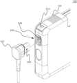
- FIG. 1is a perspective view of a Wearable Cardioverter Defibrillator (“WCD”) latching connector system of the present disclosure
- FIG. 2is an exploded partial perspective view of the WCD latching connector system of FIG. 1 ;
- FIG. 3is a perspective view of an aspect of the WCD latching connector system of FIG. 1 ;
- FIG. 4is a partial section view of the WCD latching connector system of FIG. 1 ;
- FIG. 5is a first perspective view of a WCD connector of the WCD latching connector system of FIG. 1 ;
- FIG. 6is a second perspective view of the WCD connector of FIG. 5 ;
- FIG. 7is a third perspective view of the WCD connector of FIG. 5 ;
- FIG. 8is a fourth perspective view of the WCD connector of FIG. 5 ;
- FIG. 9is a front view of the WCD connector of FIG. 5 ;
- FIG. 10is a rear view of the WCD connector of FIG. 5 ;
- FIG. 11is a top view of the WCD connector of FIG. 5 ;
- FIG. 12is a bottom view of the WCD connector of FIG. 5 ;
- FIG. 13is a right view of the WCD connector of FIG. 5 ;
- FIG. 14is a left view of the WCD connector of FIG. 5 ;
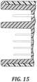
- FIG. 15is a partial section view of the WCD connector of FIG. 5 .
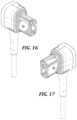
- FIG. 16is a first perspective view of another WCD connector of a WCD latching connector system of the present disclosure.
- FIG. 17is a second perspective view of the WCD connector of FIG. 16 ;
- FIG. 18is a third perspective view of the WCD connector of FIG. 16 ;
- FIG. 19is a fourth perspective view of the WCD connector of FIG. 16 ;
- FIG. 20is a front view of the WCD connector of FIG. 16 ;
- FIG. 21is a rear view of the WCD connector of FIG. 16 ;
- FIG. 22is a top view of the WCD connector of FIG. 16 ;
- FIG. 23is a bottom view of the WCD connector of FIG. 16 ;
- FIG. 24is a right view of the WCD connector of FIG. 16 ;
- FIG. 25is a left view of the WCD connector of FIG. 16 ;
- FIG. 26is a partial section view of an aspect of the WCD connector of FIG. 16 ;
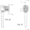
- FIG. 27is a front view of a WCD connector of FIG. 9 ;
- FIG. 28is a cross sectional view of the WCD connector of FIG. 27 ;
- FIG. 29is a top view of the WCD connector of FIG. 27 ;
- FIG. 30is a left view of the WCD connector of FIG. 27 ;
- FIG. 31is a block diagram illustrating components of a defibrillator device, which may be used with various embodiments.
- a wearable cardioverter defibrillator (“WCD”) systemincludes a WCD latching connector system that is partially integrated with a WCD monitor.
- the WCD systemmay include additional elements, including a plurality of electrodes configured for connection to a patient and to the WCD monitor, and a harness or vest for positioning the electrodes on the body of the patient.
- the WCD monitor shown in FIG. 3includes an enclosure assembly that is configured to protect defibrillator electronics contained therein (electronics are partially shown in FIG. 4 ).
- the enclosure assemblymay be a multi-piece assembly that includes a housing, a front cover, and a rear cover.
- the housinggenerally lies in between the front cover and the rear cover.
- the housing, the front cover, and the rear covermay each be constructed from one or more durable materials capable of withstanding shocks, abrasions, and other forces likely to be encountered when the WCD monitor is worn by a patient.
- the enclosure assemblyis primarily constructed of one or more plastics, for example acrylonitrile butadiene styrene and/or polycarbonate.
- the WCD latching connector systemincludes a connector and a receptacle configured to form a shielded physical and electrical connection therebetween.
- the connectorhas one or more latches, a shield (such as a metal shield), and a connector overmold.
- the receptacleextends through an outer wall of the WCD monitor, and includes a chamber having one or more electrical connections.
- the receptaclehouses a shield (such as a metal shield) and a latch configured to engage the one or more latches on the connector.
- the WCD latching connector systemmay electrically and physically connect, for example, patient-facing electrodes and the WCD monitor. Other applications are contemplated.
- the WCD latching connector systemincorporates water seals to resist ingress of water.
- the connectormay be removably inserted into the receptacle, where it engages the WCD monitor as shown in the partial section view of FIG. 4 .
- a latch of the receptacleengages a latch of the connector, locking the connector to the receptacle.
- a button on the WCD monitoris depressed, thereby unlatching the connector from the receptacle and enabling removal of the connector from the connector.
- the buttonincludes a membrane (e.g., an elastomeric membrane) to prevent water from entering the receptacle, and in particular a chamber within the receptacle.
- the WCD latching connector systemincludes one or more high voltage (HV) connections for defibrillation therapy along with one or more low voltage connections.
- the WCD latching connector systemincludes a mating shield connection in the connector and receptacle that ensures the LV and HV signals remain intact in electrically noisy environments.
- the WCD latching connector systemincludes a latching system as described above that locks the connector to the receptacle and requires a button to be depressed in order to unlatch the connector to remove the connector.
- the WCD latching connector systemincludes a connector overmold to create a water seal on the WCD housing system when inserted into the receptacle to further resist liquid from entering the receptacle chamber.
- FIGS. 5 - 15generally show an exemplary connector of the WCD latching connector system of FIGS. 1 - 4 .
- FIGS. 16 - 26generally show another exemplary connector of a WCD latching connector system of the present disclosure.
- Advantages of the disclosed WCD latches connector systeminclude actively locking the connector into the receptacle of the WCD monitor, electrically shielding the LV and HV connections to improve signal quality and sealing the receptacle chamber from water ingress.
- the WCD system 100may include a WCD connector 102 coupled with a WCD monitor 104 .
- the WCD connector 102may be shown separated from the WCD monitor 104 exposing one or more tabs 202 on the WCD connector 102 .
- the WCD connector 102may couple with the WCD monitor 104 via a receptacle 204 incorporated into the WCD monitor 104 .
- the WCD connector 102may be coupled to the WCD monitor 104 by inserting the WCD connector 102 into the receptacle 204 , where one or more tabs 202 on the WCD connector 102 may facilitate securely coupling the WCD connector 102 with the WCD monitor 104 .
- the receptacle 204may include latching features 208 . Additionally, shown on a corner proximate to the receptacle 204 may be a button 210 .
- the latching features 208may be configured to facilitate latching of the WCD connector 102 with the WCD monitor 104 .
- the one or more tabs 202may be configured to engage the latching feature 208 such as, but not limited to, a slide and catch mechanism.
- the WCD connector 104may be pushed into the receptacle 204 , where the one or more tabs 202 may mechanically engage with the latching features 208 with the latching features 208 engages the one or more tabs 202 helping to prevent removal of the WCD connector 102 from the receptacle 204 forming a water resistance seal and an electrically shielded connection.
- the WCD connector 102may be released from the WCD monitor 104 by depressing the button 210 , which may actuate the latching features 208 to release the one or more tabs 202 facilitating removal of the WCD connector 102 from the receptacle 204 .
- the one or more tabs 202may be part of the latching system with a complimentary latching receiver (latching features 208 ) included in the WCD monitor 104 to facilitate a relatively sealed coupling of various electrical coupling components.
- the WCD latching connector system 400includes a WCD connector 402 and a WCD monitor 404 .
- the WCD connector 402may be coupled with the WCD monitor 404 by inserting the WCD connector 402 into a receptacle 406 .
- the WCD connector 402may have a shield, a connector shield 408 with the WCD monitor 404 having a shield of its own, a monitor shield 410 .
- the connector shield 408 and the monitor shield 410may be configured to facilitate shielding of the connection between the WCD connector 402 and the WCD monitor 404 .
- the connector shield 408may be made of metals such as, but not limited to, magnesium-zinc alloy, aluminum alloy, or zinc alloy. In one example, the connector shield 408 may be made of a die cast zinc alloy part with nickel plating to help facilitate corrosion resistance.
- the monitor shield 410may also be made of metals such as, but not limited to, magnesium-zinc alloy, aluminum alloy, zinc alloy, beryllium-based alloys. In one example, the monitor shield 410 may be made of beryllium copper alloy, which may also facilitate corrosion resistance.
- the beryllium copper alloymay facilitate reduction of fatigue of the monitor shield 410 due to deflection during engagement with the connector shield 408 (e.g., the monitor shield 410 may deflect and spring back for many cycles of engagement with the connector shield 408 ).
- the connector shield 408 and the monitor shield 410may facilitate shielding of various electrical coupling components, thereby facilitating shielding of the electrical signals from noise and various artifacts, in accordance with various embodiments.
- FIG. 4Another feature shown in FIG. 4 may be some baffle like structures 412 to facilitate prevention of ingress of water as described.
- the ingress of water or water preventionmay be expressed as Ingress Protection (e.g., IP or IPX rating).
- IP ratingmay be between IPX2 and IPX4. That is, the WCD connector 402 and the WCD monitor 404 may have an IP rating of IPX2 to IPX4, respectively.
- the enclosure assemblyis primarily constructed of one or more plastics, for example acrylonitrile butadiene styrene and/or polycarbonate.
- plasticsfor example acrylonitrile butadiene styrene and/or polycarbonate.
- the latching features 208 inside the receptacle 204 of the WCD monitor 104may be made of a combination of plastic type material such as, but not limited to, a Polyoxymethylene based engineered thermoplastic (e.g., Derlin® available from Dupont de Nemours, Inc.), Polybutylene Terephthalate (PBT) (e.g., glass filled PBT), Polycarbonate/Acrylonitrile Butadiene Styrene (PC/ABS), and/or any combination thereof.
- PBTPolybutylene Terephthalate
- PC/ABSPolycarbonate/Acrylonitrile Butadiene Styrene
- the choice of the above example plastic type materialsmay be based, at least in part, on consideration for how the plastic type materials may interact with one another.
- some of the moving parts of the latching feature 208may be made of PBT, while the other parts may be made of Derlin®. This combination may help to reduce the potential for chemical bonding (e.g., between the plastic parts) or covalent bonding.
- Embodiments of the WCD latching connector systemmay include combinations and sub-combinations of features described or shown in the drawings herein, including for example, embodiments that are equivalent to: providing or applying a feature in a different order than in a described embodiment, extracting an individual feature from one embodiment and inserting such feature into another embodiment; removing one or more features from an embodiment; or both removing one or more features from an embodiment and adding one or more features extracted from one or more other embodiments, while providing the advantages of the features incorporated in such combinations and sub-combinations.
- feature or featurescan refer to the structures and/or functions of an apparatus, article of manufacture or monitor, and/or the steps, acts, or modalities of a method.
- the electrical connection pinsmay include two high voltage connection pins 902 and 13 low voltage connection pins 904 . As shown, each of the two high voltage connection pins 902 may be separated by a first plastic feature 908 . The 13 low voltage connection pins 904 may be collectively separated by a second plastic feature 910 . The first and second plastic features 908 and 910 may be configured to facilitate control of creepage and clearance distances between each of the two high voltage connection pins 902 and between the two high voltage connections pins 902 with the 13 low voltage connection pins 904 . In FIG.
- the overall layout of the two high voltage connection pins 902 and the 13 low voltage connection pins 904may be in a shape that may be described as a trapezoidal type shape 906 (e.g., approximately a right trapezoidal shape).
- the 13 low voltage connection pins 904i.e., the second plastic feature 910
- the 13 low voltage connection pins 904may have a layout that substantially follows the trapezoidal type shape 906 with the two high voltage connection pins 902 being aligned along a sloping side 912 of the trapezoidal type shape 906 .
- the layout of the two high voltage connection pins 902 and the 13 low voltage connection pins 904 including the first plastic feature 908 and the second plastic feature 910 in the trapezoidal type shape 906helps facilitate control of creepage and clearance distances along with a relatively small form factor.
- the connector shielding 408(shown in FIG. 4 ) may be configured to substantially surround the electrical connection pins 902 and 904 .
- number of pins for the both the high voltage connections pins 902 low voltage connection pins 904may vary based at least, in part, on the application (e.g., type of wearable medical device). That is, the number of electrical connection pins may vary (e.g., two high electrical connection pins and 7 or more electrical connection pins), and accordingly, the claimed subject matter is not limited in this respect.
- FIGS. 27 - 30illustrates various views of a WCD connector, in accordance with a non-limiting example.
- the WCD connectormay have example dimension to facilitate distances between the various components.
- the non-limiting dimensions shown in FIGS. 27 - 30may help facilitate management of arching and electrostatic discharge in dielectric materials.
- the example dimensions shown in FIGS. 27 - 30may facilitate clearance and creepage distances of the electrical connection pins (e.g., the high voltage connection pins 902 ), as described above with respect to FIG. 9 .
- the materials for the various components of the WCD connector 102may include dielectric materials such as, but not limited to, low density polyethylene, polyimide, etc. It should be appreciated that example dimensions shown in FIGS. 27 - 30 may vary based, at least in part, on the number of electrical connection pins electrical connection pins 902 and 904 (shown in FIG. 9 ), and accordingly, the example dimensions shown in FIGS. 27 - 30 are but an example and is not limiting to the scope of the disclosed subject matter.
- FIG. 31is a block diagram illustrating components of a defibrillator device, which may be used with various embodiments. These components may be, for example, components of a WCD system 100 and 400 (shown in FIGS. 1 and 4 ).
- the defibrillator device 3100may be some of the above examples of one or more WCD systems 100 and 400 intended for use by a user 3180 .
- the defibrillator device 3100may typically include a defibrillation port 3110 , such as a socket in housing 3101 (e.g., latching connector system in FIGS. 1 - 4 ).
- the defibrillation port 3110may include nodes 3114 and 3118 .
- One or more electrodes 3104 and 3108which may be plugged into the defibrillation port 3110 , so as to make electrical contact with nodes 3114 and 3118 , respectively.
- the electrodes 3104 and 3108may be connected continuously to the defibrillation port 3110 , etc. Either way, the defibrillation port 3110 may be used for guiding via the electrodes 3104 and 3108 to a person 3180 an electrical charge that may have been stored in the defibrillator device 3100 , as described herein.
- the defibrillator device 3100may also have an ECG port 3119 in the housing 3101 (e.g., WCD monitor 104 and 400 in FIGS. 1 - 4 ), for receiving ECG cables 3109 .
- the ECG cables 3109may facilitate sensing of an ECG signal (e.g., a 12-lead signal or from a different number of lead signals).
- a defibrillator-monitorcould have additional ports (not shown), and the other component 3125 may be configured to filter the ECG signal (e.g., application of at least one filter to the signal to help facilitate removal of artifacts such as, but not limited to, chest compression due to chest compressions being delivered to the person).
- the defibrillator 3100also may include a measurement circuit 3120 .
- the measurement circuit 3120may receive physiological signals from the ECG port 3119 , and also from other ports, if provided.
- the circuit 3120may render detected physiological signals and their corresponding information.
- the informationmay be in the form of data, or other signals, etc.
- ECG port 3119may not be present.
- the measurement circuit 3120may obtain physiological signals through the nodes 3114 and 3118 instead, when the electrodes 3104 and 3108 are attached to the person 3180 .
- a person's ECG signalmay be detected as a voltage difference between the electrodes 3104 and 3108 .
- the impedance between the electrodes 3104 and 3108may be detected, among other things, whether the electrodes 3104 and 3108 have been inadvertently disconnected from the person 3180 .
- the defibrillator 3100may also include a processor 3130 .
- the processor 3130may be implemented in a wide variety of manners for causing actions and operations to be performed. Some examples may include digital and/or analog processors such as microprocessors and digital-signal processors (DSPs), controllers such as microcontrollers, software running in a machine environment, programmable circuits such as Field Programmable Gate Arrays (FPGAs), Field-Programmable Analog Arrays (FPAAs), Programmable Logic Devices (PLDs), Application Specific Integrated Circuits (ASICs), and so on or any combination thereof.
- DSPsdigital and/or analog processors
- DSPsdigital-signal processors
- controllerssuch as microcontrollers
- software running in a machine environmentprogrammable circuits such as Field Programmable Gate Arrays (FPGAs), Field-Programmable Analog Arrays (FPAAs), Programmable Logic Devices (PLDs), Application Specific Integrated Circuits (ASICs),
- the processor 3130may include a number of modules.
- One example modulemay be a detection module 532 , which may detect outputs from the measurement circuit 3120 .
- the detection module 3132may include a VF detector. Accordingly, the person's detected ECG may be utilized to help determine whether the person is experiencing ventricular fibrillation (VF).
- VFventricular fibrillation
- modulemay be an advice module 3134 , which may provide advice based, at least in part, on outputs of detection module 532 .
- the advice module 3134may include an algorithm such as, but not limited to, Shock Advisory Algorithm, implement decision rules, and so on.
- the advicemay be to shock, to not shock, to administer other forms of therapy, and so on. If the advice is to shock, some defibrillator examples may report the advice to the user, and prompt them to do it. In other examples, the defibrillator device may execute the advice by administering the shock. If the advice is to administer CPR, the defibrillator 3100 may further issue prompts for administrating CPR, and so forth.
- the processor 3130may include additional modules, such as module 3136 for various other functions. Additionally, if other component 3125 is provided, it may be operated in part by processor 3130 , etc.
- the defibrillator device 3100may include a memory 3138 , which may work together with the processor 3130 .
- the memory 3138may be implemented in a wide variety of manners.
- the memory 3138may be implemented such as, but not limited to, nonvolatile memories (NVM), read-only memories (ROM), random access memories (RAM), and so forth or any combination thereof.
- the memory 3138may can include programs for the processor 3130 , and so on.
- the programsmay include operational programs execution by the processor 530 and may also include protocols and methodologies that decisions may be made by advice module 3134 .
- the memory 3138may store various prompts for the user 3180 , etc.
- the memory 3138may store a wide variety of information (i.e., data) such as, but not limited to information regarding the person.
- the defibrillator 3100may also include a power source 3140 .
- the power source 3140may include a battery type device.
- a battery type devicemay be implemented as a battery pack, which may be rechargeable or not be rechargeable. At times, a combination of rechargeable and non-rechargeable battery packs may be utilized.
- Examples of power source 3140may include AC power override, where AC power may be available, and so on.
- the processor 3130may control the power source 3140 .
- the defibrillator device 3100may include an energy storage module 3150 .
- the energy storage module 3150may be configured to store some electrical energy (e.g., when preparing for sudden discharge to administer a shock).
- the energy storage module 3150may be charged from the power source 3140 to an appropriate level of energy, as may be controlled by the processor 3130 .
- the energy storage module 3150may include one or more capacitors 3152 , and the like.
- the defibrillator 3100may include a discharge circuit 3155 .
- the discharge circuit 3155may be controlled to facilitate discharging of the energy stored in energy storage module 3150 to the nodes 3114 and 3118 , and also to electrodes 3104 and 3108 .
- the discharge circuit 3155may include one or more switches 3157 .
- the one or more switches 3157may be configured in a number of manners such as, but not limited to, an H-bridge, and so forth.
- the defibrillator device 3100may further include a user interface 3170 for the user 3180 .
- the user interface 3170may be implemented in a variety of manners.
- the user interface 3170may include a display screen capable of displaying what is detected and measured, provide visual feedback to the user 3180 for their resuscitation attempts, and so forth.
- the user interface 3170may also include an audio output such as, but not limited to, a speaker to issue audio prompts, etc.
- the user interface 3170may additionally include various control devices such as, but not limited to, pushbuttons, touch display, and so forth.
- the discharge circuit 3155may be controlled by the processor 3130 or directly by the user 3180 via the user interface 3170 , and so forth.
- the defibrillator device 3100may include other components.
- a communication module 3190may be provided for communicating with other machines and/or the electrodes. Such communication may be performed wirelessly, or via wire, or by infrared communication, and so forth. Accordingly, information may be communicated, such as person data, incident information, therapy attempted, CPR performance, ECG information, and so forth.
- FIGS. 1 - 31illustrative implementations of the disclosure may have been described with reference to the elements of the components described with respect to FIGS. 1 - 31 . However, the described embodiments are not limited to these depictions. More specifically, some elements/components depicted in FIGS. 1 - 31 may be omitted from some implementations detailed herein. Furthermore, other elements not depicted in FIGS. 1 - 31 may be used to implement example apparatuses detailed herein.
- the present applicationmay also reference quantities and numbers. Unless specifically stated, such quantities and numbers are not to be considered restrictive, but exemplary of the possible quantities or numbers associated with the present application. Also, in this regard, the present application may use the term “plurality” to reference a quantity or number. In this regard, the term “plurality” is meant to be any number that is more than one, for example, two, three, four, five, etc. The terms “about,” “approximately,” “near,” etc., mean plus or minus 5% of the stated value.
- the phrase “at least one of A, B, and C,” for example,means (A), (B), (C), (A and B), (A and C), (B and C), or (A, B, and C), including all further possible permutations when greater than three elements are listed.
Landscapes
- Health & Medical Sciences (AREA)
- Life Sciences & Earth Sciences (AREA)
- Engineering & Computer Science (AREA)
- Animal Behavior & Ethology (AREA)
- Biomedical Technology (AREA)
- Nuclear Medicine, Radiotherapy & Molecular Imaging (AREA)
- Radiology & Medical Imaging (AREA)
- General Health & Medical Sciences (AREA)
- Public Health (AREA)
- Veterinary Medicine (AREA)
- Cardiology (AREA)
- Heart & Thoracic Surgery (AREA)
- Human Computer Interaction (AREA)
- Biophysics (AREA)
- Electrotherapy Devices (AREA)
Abstract
Description
Claims (20)
Priority Applications (2)
| Application Number | Priority Date | Filing Date | Title |
|---|---|---|---|
| US16/994,525US11724116B2 (en) | 2018-02-15 | 2020-08-14 | Wearable cardioverter defibrillator latching connector |
| US18/234,108US12233271B2 (en) | 2018-02-15 | 2023-08-15 | Wearable cardioverter defibrillator latching connector |
Applications Claiming Priority (3)
| Application Number | Priority Date | Filing Date | Title |
|---|---|---|---|
| US201862630995P | 2018-02-15 | 2018-02-15 | |
| US16/277,838US20190247671A1 (en) | 2018-02-15 | 2019-02-15 | Wearable cardioverter defibrillator latching connector |
| US16/994,525US11724116B2 (en) | 2018-02-15 | 2020-08-14 | Wearable cardioverter defibrillator latching connector |
Related Parent Applications (1)
| Application Number | Title | Priority Date | Filing Date |
|---|---|---|---|
| US16/277,838Continuation-In-PartUS20190247671A1 (en) | 2018-02-15 | 2019-02-15 | Wearable cardioverter defibrillator latching connector |
Related Child Applications (1)
| Application Number | Title | Priority Date | Filing Date |
|---|---|---|---|
| US18/234,108ContinuationUS12233271B2 (en) | 2018-02-15 | 2023-08-15 | Wearable cardioverter defibrillator latching connector |
Publications (2)
| Publication Number | Publication Date |
|---|---|
| US20200406044A1 US20200406044A1 (en) | 2020-12-31 |
| US11724116B2true US11724116B2 (en) | 2023-08-15 |
Family
ID=74044236
Family Applications (2)
| Application Number | Title | Priority Date | Filing Date |
|---|---|---|---|
| US16/994,525Active2039-11-01US11724116B2 (en) | 2018-02-15 | 2020-08-14 | Wearable cardioverter defibrillator latching connector |
| US18/234,108ActiveUS12233271B2 (en) | 2018-02-15 | 2023-08-15 | Wearable cardioverter defibrillator latching connector |
Family Applications After (1)
| Application Number | Title | Priority Date | Filing Date |
|---|---|---|---|
| US18/234,108ActiveUS12233271B2 (en) | 2018-02-15 | 2023-08-15 | Wearable cardioverter defibrillator latching connector |
Country Status (1)
| Country | Link |
|---|---|
| US (2) | US11724116B2 (en) |
Citations (88)
| Publication number | Priority date | Publication date | Assignee | Title |
|---|---|---|---|---|
| US3724355A (en) | 1970-06-12 | 1973-04-03 | K Schranz | Apparatus for processing exposed photographic film or the like |
| US4583524A (en) | 1984-11-21 | 1986-04-22 | Hutchins Donald C | Cardiopulmonary resuscitation prompting |
| US4619265A (en) | 1984-03-08 | 1986-10-28 | Physio-Control Corporation | Interactive portable defibrillator including ECG detection circuit |
| US4928690A (en) | 1988-04-25 | 1990-05-29 | Lifecor, Inc. | Portable device for sensing cardiac function and automatically delivering electrical therapy |
| US4955381A (en) | 1988-08-26 | 1990-09-11 | Cardiotronics, Inc. | Multi-pad, multi-function electrode |
| US5078134A (en) | 1988-04-25 | 1992-01-07 | Lifecor, Inc. | Portable device for sensing cardiac function and automatically delivering electrical therapy |
| US5228449A (en) | 1991-01-22 | 1993-07-20 | Athanasios G. Christ | System and method for detecting out-of-hospital cardiac emergencies and summoning emergency assistance |
| US5348008A (en) | 1991-11-25 | 1994-09-20 | Somnus Corporation | Cardiorespiratory alert system |
| US5394892A (en) | 1990-04-02 | 1995-03-07 | K J Mellet Nominees Pty Ltd | CPR prompting apparatus |
| US5405362A (en) | 1991-04-29 | 1995-04-11 | The Board Of Regents For The University Of Texas System | Interactive external defibrillation and drug injection system |
| US5474574A (en) | 1992-06-24 | 1995-12-12 | Cardiac Science, Inc. | Automatic external cardioverter/defibrillator |
| US5618208A (en)* | 1994-06-03 | 1997-04-08 | Siemens Medical Systems, Inc. | Fully insulated, fully shielded electrical connector arrangement |
| US5662690A (en) | 1994-12-08 | 1997-09-02 | Heartstream, Inc. | Defibrillator with training features and pause actuator |
| US5782878A (en) | 1994-12-07 | 1998-07-21 | Heartstream, Inc. | External defibrillator with communications network link |
| US5792204A (en) | 1996-05-08 | 1998-08-11 | Pacesetter, Inc. | Methods and apparatus for controlling an implantable device programmer using voice commands |
| WO1998039061A2 (en) | 1997-03-07 | 1998-09-11 | Cadent Medical Corporation | Wearable defibrillation system |
| US5902249A (en) | 1995-03-03 | 1999-05-11 | Heartstream, Inc. | Method and apparatus for detecting artifacts using common-mode signals in differential signal detectors |
| US5913685A (en) | 1996-06-24 | 1999-06-22 | Hutchins; Donald C. | CPR computer aiding |
| US5944669A (en) | 1997-11-20 | 1999-08-31 | Lifecor, Inc. | Apparatus and method for sensing cardiac function |
| US6047203A (en) | 1997-03-17 | 2000-04-04 | Nims, Inc. | Physiologic signs feedback system |
| US6065154A (en) | 1998-04-07 | 2000-05-23 | Lifecor, Inc. | Support garments for patient-worn energy delivery apparatus |
| US6108197A (en) | 1992-05-15 | 2000-08-22 | Via, Inc. | Flexible wearable computer |
| US6201992B1 (en) | 1999-04-01 | 2001-03-13 | Agilent Technologies, Inc. | Defibrillator interface capable of generating video images |
| US6263238B1 (en) | 1998-04-16 | 2001-07-17 | Survivalink Corporation | Automatic external defibrillator having a ventricular fibrillation detector |
| US6287328B1 (en) | 1999-04-08 | 2001-09-11 | Agilent Technologies, Inc. | Multivariable artifact assessment |
| US6319011B1 (en) | 1995-04-06 | 2001-11-20 | Michael J. Motti | Automatic training defibrillator simulator and method |
| US6334070B1 (en) | 1998-11-20 | 2001-12-25 | Medtronic Physio-Control Manufacturing Corp. | Visual and aural user interface for an automated external defibrillator |
| US6356785B1 (en) | 1997-11-06 | 2002-03-12 | Cecily Anne Snyder | External defibrillator with CPR prompts and ACLS prompts and methods of use |
| US6437083B1 (en) | 2001-12-06 | 2002-08-20 | General Electric Company | Process for preparing branched aromatic polycarbonates |
| US6529875B1 (en) | 1996-07-11 | 2003-03-04 | Sega Enterprises Ltd. | Voice recognizer, voice recognizing method and game machine using them |
| US20030158593A1 (en) | 2002-02-19 | 2003-08-21 | Heilman Marlin S. | Cardiac garment |
| US6681003B2 (en) | 1999-10-05 | 2004-01-20 | Lifecor, Inc. | Data collection and system management for patient-worn medical devices |
| US6762917B1 (en) | 2001-06-12 | 2004-07-13 | Novx Corporation | Method of monitoring ESC levels and protective devices utilizing the method |
| US20050107833A1 (en) | 2003-11-13 | 2005-05-19 | Freeman Gary A. | Multi-path transthoracic defibrillation and cardioversion |
| US7065401B2 (en) | 2002-05-08 | 2006-06-20 | Michael Worden | Method of applying electrical signals to a patient and automatic wearable external defibrillator |
| US20060173499A1 (en) | 2005-01-31 | 2006-08-03 | Medtronic Emergency Response Systems, Inc. | System and method for using diagnostic pulses in connection with defibrillation therapy |
| US20080033495A1 (en) | 2006-08-01 | 2008-02-07 | Kumar Uday N | External Defibrillator |
| US20080312709A1 (en) | 2007-06-13 | 2008-12-18 | Volpe Shane S | Wearable medical treatment device with motion/position detection |
| US20090005827A1 (en) | 2007-06-26 | 2009-01-01 | David Weintraub | Wearable defibrillator |
| US7559902B2 (en) | 2003-08-22 | 2009-07-14 | Foster-Miller, Inc. | Physiological monitoring garment |
| US20090187229A1 (en)* | 2007-04-11 | 2009-07-23 | Pacesetter, Inc. | Capacitor-integrated feedthrough assembly with improved grounding for an implantable medical device |
| US20100007413A1 (en) | 2006-11-10 | 2010-01-14 | Koninklijke Philips Electronics N.V. | Ecg electrode contact quality measurement system |
| US20100298899A1 (en) | 2007-06-13 | 2010-11-25 | Donnelly Edward J | Wearable medical treatment device |
| US7865238B2 (en) | 2004-09-29 | 2011-01-04 | Koninklijke Philips Electronics N.V. | High-voltage module for an external defibrillator |
| US7870761B2 (en) | 2002-05-14 | 2011-01-18 | Koninklijke Philips Electronics N.V. | Garment and method for producing the same |
| US20110288604A1 (en) | 2010-05-18 | 2011-11-24 | Kaib Thomas E | Wearable therapeutic device |
| US20110288605A1 (en) | 2010-05-18 | 2011-11-24 | Zoll Medical Corporation | Wearable ambulatory medical device with multiple sensing electrodes |
| US8135462B2 (en) | 2002-08-26 | 2012-03-13 | Physio-Control, Inc. | Pulse detection using patient physiological signals |
| US20120112903A1 (en) | 2010-11-08 | 2012-05-10 | Zoll Medical Corporation | Remote medical device alarm |
| US20120150008A1 (en) | 2010-12-09 | 2012-06-14 | Kaib Thomas E | Electrode with redundant impedance reduction |
| US20120144551A1 (en) | 2010-12-09 | 2012-06-14 | Eric Guldalian | Conductive Garment |
| US20120158075A1 (en) | 2010-12-16 | 2012-06-21 | Kaib Thomas E | Water resistant wearable medical device |
| US20120265265A1 (en) | 2011-04-13 | 2012-10-18 | Mehdi Razavi | Automated External Defibrillator Pad System |
| US20120283794A1 (en) | 2011-05-02 | 2012-11-08 | Kaib Thomas E | Patient-worn energy delivery apparatus and techniques for sizing same |
| US20120293323A1 (en) | 2011-03-25 | 2012-11-22 | Zoll Medical Corporation | System and method for adapting alarms in a wearable medical device |
| US20120302860A1 (en) | 2011-03-25 | 2012-11-29 | Zoll Medical Corporation | Selection of optimal channel for rate determination |
| US20120310315A1 (en) | 2009-03-17 | 2012-12-06 | Savage Walter T | Device and method for reducing patient transthoracic impedance for the purpose of delivering a therapeutic current |
| US8369944B2 (en) | 2007-06-06 | 2013-02-05 | Zoll Medical Corporation | Wearable defibrillator with audio input/output |
| US20130085538A1 (en) | 2011-09-01 | 2013-04-04 | Zoll Medical Corporation | Wearable monitoring and treatment device |
| US20130231711A1 (en)* | 2012-03-02 | 2013-09-05 | Thomas E. Kaib | Systems and methods for configuring a wearable medical monitoring and/or treatment device |
| US20130245388A1 (en) | 2011-09-01 | 2013-09-19 | Mc10, Inc. | Electronics for detection of a condition of tissue |
| US8548557B2 (en) | 2010-08-12 | 2013-10-01 | Covidien Lp | Medical electrodes |
| US20130274565A1 (en) | 2012-04-13 | 2013-10-17 | Alois Antonin Langer | Outpatient health emergency warning system |
| US20130289637A1 (en)* | 2012-04-27 | 2013-10-31 | Pacesetter, Inc. | Electromagnetic interference shielding for use with an implantable medical device incorporating a radio transceiver |
| US20130317852A1 (en) | 2012-05-22 | 2013-11-28 | Geneva Healthcare, LLC | Medical device information portal |
| US20130325078A1 (en) | 2012-05-31 | 2013-12-05 | Zoll Medical Corporation | Medical monitoring and treatment device with external pacing |
| US20130325096A1 (en) | 2012-05-31 | 2013-12-05 | Zoll Medical Corporation | Long term wear multifunction biomedical electrode |
| US8615295B2 (en) | 2009-03-17 | 2013-12-24 | Cardiothrive, Inc. | External defibrillator |
| US20140012144A1 (en) | 2012-07-09 | 2014-01-09 | William E. Crone | Perfusion detection system |
| US20140025131A1 (en) | 2012-07-20 | 2014-01-23 | Physio-Control, Inc. | Wearable defibrillator with voice prompts and voice recognition |
| US20140046391A1 (en) | 2012-08-10 | 2014-02-13 | Physio-Control, Inc. | Wearable defibrillator system communicating via mobile communication device |
| US20140070957A1 (en) | 2012-09-11 | 2014-03-13 | Gianluigi LONGINOTTI-BUITONI | Wearable communication platform |
| US20140163663A1 (en) | 2012-12-11 | 2014-06-12 | Piyush Poddar | Method and system for switching shock vectors and decreasing transthoracic impedance for cardioversion and defibrillation |
| US8904214B2 (en) | 2010-07-09 | 2014-12-02 | Zoll Medical Corporation | System and method for conserving power in a medical device |
| US20140378812A1 (en) | 2011-12-20 | 2014-12-25 | Sensible Medical Innovatons | Thoracic garment of positioning electromagnetic (em) transducers and methods of using such thoracic garment |
| US20150039053A1 (en) | 2013-06-28 | 2015-02-05 | Zoll Medical Corporation | Systems and methods of delivering therapy using an ambulatory medical device |
| US9089685B2 (en) | 2013-02-25 | 2015-07-28 | West Affum Holdings Corp. | Wearable defibrillator with a multivector shock waveform |
| US9132267B2 (en) | 2013-03-04 | 2015-09-15 | Zoll Medical Corporation | Flexible therapy electrode system |
| US20150328472A1 (en) | 2014-05-13 | 2015-11-19 | Physio-Control, Inc. | Wearable cardioverter defibrillator components discarding ecg signals prior to making shock/no shock determination |
| US20160004831A1 (en) | 2014-07-07 | 2016-01-07 | Zoll Medical Corporation | Medical device with natural language processor |
| US20160082277A1 (en) | 2013-02-25 | 2016-03-24 | West Affum Holdings Corp. | Wearable cardioverter defibrillator (wcd) system informing patient that it is validating just-detected cardiac arrhythmia |
| US20160256676A1 (en) | 2015-03-06 | 2016-09-08 | Zoll Medical Corporation | Long-Term Wear Electrode |
| US9592403B2 (en) | 2013-02-25 | 2017-03-14 | West Affum Holdings Corp. | Wearable cardioverter defibrillator (WCD) system making shock/no shock determinations from multiple patient parameters |
| US20190022400A1 (en) | 2015-08-26 | 2019-01-24 | Element Science, Inc. | Wearable devices |
| US20190159696A1 (en) | 2014-10-30 | 2019-05-30 | West Affum Holdings Corp. | Wearable cardioverter defibrillator with improved ecg electrodes |
| EP3380189B1 (en) | 2015-11-23 | 2020-08-12 | Zoll Medical Corporation | Garments for wearable medical devices |
| US20220249854A1 (en) | 2021-02-08 | 2022-08-11 | Zoll Medical Corporation | Modular ingress protected electrode system for a wearable defibrillator |
| US20220370788A1 (en) | 2019-12-30 | 2022-11-24 | Zoll Medical Corporation | Wearable Medical Device with Removable Support Garment |
Family Cites Families (63)
| Publication number | Priority date | Publication date | Assignee | Title |
|---|---|---|---|---|
| US3724455A (en) | 1970-06-02 | 1973-04-03 | P Unger | Cardiac warning device |
| US4666432A (en) | 1985-09-13 | 1987-05-19 | Mcneish Kenneth | Catheter retaining means and method |
| US4698848A (en) | 1986-09-26 | 1987-10-13 | Buckley Mary C | Blouse for cardiac patients |
| US5429593A (en) | 1993-12-23 | 1995-07-04 | Matory; Yvedt L. | Post-surgical, drainage accommodating, compression dressing |
| US5708978A (en) | 1994-08-17 | 1998-01-20 | Johnsrud; Anna C. | Medical vest |
| US5741306A (en) | 1996-05-23 | 1998-04-21 | Lifecor, Inc. | Patient-worn energy delivery apparatus |
| US6280461B1 (en) | 1996-05-23 | 2001-08-28 | Lifecor, Inc. | Patient-worn energy delivery apparatus |
| US6450942B1 (en) | 1999-08-20 | 2002-09-17 | Cardiorest International Ltd. | Method for reducing heart loads in mammals |
| US7120495B2 (en) | 2000-09-18 | 2006-10-10 | Cameron Health, Inc. | Flexible subcutaneous implantable cardioverter-defibrillator |
| JP4674212B2 (en) | 2003-11-26 | 2011-04-20 | カーディオネット インコーポレーテッド | Systems and methods for processing and displaying arrhythmia information to facilitate identification and treatment of cardiac arrhythmias |
| US7194300B2 (en) | 2004-01-21 | 2007-03-20 | Cardionet, Inc. | Cardiac monitoring |
| US7587237B2 (en) | 2004-02-02 | 2009-09-08 | Cardionet, Inc. | Biological signal management |
| US7099715B2 (en) | 2004-02-17 | 2006-08-29 | Cardionet, Inc. | Distributed cardiac activity monitoring with selective filtering |
| US8972017B2 (en) | 2005-11-16 | 2015-03-03 | Bioness Neuromodulation Ltd. | Gait modulation system and method |
| DE102005060985A1 (en) | 2005-12-20 | 2007-06-28 | Oestreich, Wolfgang, Dr.med. | System for mobile monitoring of heart functions has electrodes which are connected to central administrative unit through electrical conductors and these conductors are arranged in clothing |
| US7653431B2 (en) | 2005-12-20 | 2010-01-26 | Cardiac Pacemakers, Inc. | Arrhythmia discrimination based on determination of rate dependency |
| US7738965B2 (en) | 2006-04-28 | 2010-06-15 | Medtronic, Inc. | Holster for charging pectorally implanted medical devices |
| US8560044B2 (en) | 2007-05-16 | 2013-10-15 | Medicomp, Inc. | Garment accessory with electrocardiogram sensors |
| US8527028B2 (en) | 2007-05-16 | 2013-09-03 | Medicomp, Inc. | Harness with sensors |
| US20100198044A1 (en)* | 2007-07-06 | 2010-08-05 | Koninklijke Philips Electronics N.V. | Shielded biomedical electrode patch |
| EP3922171A1 (en) | 2007-09-14 | 2021-12-15 | Medtronic Monitoring, Inc. | Adherent cardiac monitor with advanced sensing capabilities |
| WO2009036316A1 (en) | 2007-09-14 | 2009-03-19 | Corventis, Inc. | Energy management, tracking and security for adherent patient monitor |
| US8116841B2 (en) | 2007-09-14 | 2012-02-14 | Corventis, Inc. | Adherent device with multiple physiological sensors |
| EP2194858B1 (en) | 2007-09-14 | 2017-11-22 | Corventis, Inc. | Medical device automatic start-up upon contact to patient tissue |
| US8626297B2 (en) | 2007-09-20 | 2014-01-07 | Boston Scientific Neuromodulation Corporation | Apparatus and methods for charging an implanted medical device power source |
| US7753759B2 (en) | 2007-10-22 | 2010-07-13 | Tammy Pintor | Article of apparel for concealing objects |
| EP2446926B1 (en) | 2008-05-07 | 2013-06-26 | Cameron Health, Inc. | Devices for accurately classifying cardiac activity |
| JP5559810B2 (en) | 2008-12-15 | 2014-07-23 | コーヴェンティス,インク. | Patient monitoring system and method |
| JP5988991B2 (en) | 2010-12-10 | 2016-09-07 | ゾール メディカル コーポレイションZOLL Medical Corporation | Wearable treatment device |
| US20120191476A1 (en) | 2011-01-20 | 2012-07-26 | Reid C Shane | Systems and methods for collection, organization and display of ems information |
| EP2702621B1 (en) | 2011-04-28 | 2016-06-22 | Zoll Circulation, Inc. | Latch mechanism for battery retention |
| BR112013032419A2 (en) | 2011-06-20 | 2017-01-17 | Healthwatch Ltd | Independent, non-interfering usable health monitoring and alert system |
| US8742349B2 (en) | 2011-09-21 | 2014-06-03 | Carestream Health, Inc. | Portable radiographic detector exterior battery latch and methods for using the same |
| JP6407881B2 (en) | 2012-11-24 | 2018-10-17 | ヘルスウォッチ・リミテッドHealthwatch Ltd. | Float loop type fabric electrode and knitting method thereof |
| US9345898B2 (en) | 2013-01-23 | 2016-05-24 | West Affum Holdings Corp. | Wearable cardiac defibrillator system controlling conductive fluid deployment |
| CN105007769B (en) | 2013-02-13 | 2017-03-08 | 健康监测有限公司 | Method for limiting the elasticity of selection area in knitted fabric |
| US10500403B2 (en) | 2013-02-25 | 2019-12-10 | West Affum Holdings Corp. | WCD system validating detected cardiac arrhythmias thoroughly so as to not sound loudly due to some quickly self-terminating cardiac arrhythmias |
| US10016613B2 (en) | 2013-04-02 | 2018-07-10 | West Affum Holdings Corp. | Wearable cardiac defibrillator system long-term monitoring alternating patient parameters other than ECG |
| US20160113581A1 (en) | 2013-06-07 | 2016-04-28 | Healthwatch Ltd. | Docking station for smart garments |
| US10279189B2 (en) | 2013-06-14 | 2019-05-07 | Cardiothrive, Inc. | Wearable multiphasic cardioverter defibrillator system and method |
| US9955938B2 (en) | 2013-06-26 | 2018-05-01 | Zoll Medical Corporation | Therapeutic device including acoustic sensor |
| IN2015DN02541A (en) | 2013-10-18 | 2015-09-11 | Healthwatch Ltd | |
| US10188159B2 (en) | 2013-10-25 | 2019-01-29 | Armour Technologies, Inc. | Apparatus, system, and method for reducing head or neck trauma |
| AU2014362378A1 (en) | 2013-12-11 | 2016-06-23 | Uber Technologies, Inc. | Optimizing selection of drivers for transport requests |
| SG11201607189VA (en) | 2014-03-09 | 2016-09-29 | Healthwatch Ltd | Elastic conductive stripe and methods of utilizing thereof |
| RU2016144983A (en) | 2014-04-17 | 2018-05-16 | Хелсуотч Лтд. | DEVICES AND METHODS FOR OBTAINING WORKING ECG SIGNALS BY USING DRY KNITTED ELECTRODES |
| KR101968941B1 (en) | 2014-04-18 | 2019-04-15 | 헬스와치 리미티드 | Connector and cable assembly for smart garments |
| US20180116537A1 (en) | 2014-07-07 | 2018-05-03 | Zoll Medical Corporation | System and Method for Distinguishing a Cardiac Event From Noise in an Electrocardiogram (ECG) Signal |
| US9724008B2 (en) | 2014-07-07 | 2017-08-08 | Zoll Medical Corporation | System and method for distinguishing a cardiac event from noise in an electrocardiogram (ECG) signal |
| US20160076175A1 (en) | 2014-09-11 | 2016-03-17 | Myant Capital Partners Inc. | Compression fabrics with tailored comfort |
| CA2904754C (en) | 2014-09-17 | 2023-01-24 | Myant Capitals Partners Inc. | Seamless silhouette with engineered insulation property |
| CN107106857B (en) | 2014-12-18 | 2021-06-08 | 皇家飞利浦有限公司 | Wearable Cardioverter Defibrillator (WCD) apparatus and method for improved comfort and longer wearing |
| US9886680B2 (en) | 2015-03-24 | 2018-02-06 | Zoll Medical Corporation | Low-power signaling for medical devices and medical device personnel |
| US9901741B2 (en) | 2015-05-11 | 2018-02-27 | Physio-Control, Inc. | Wearable cardioverter defibrillator (WCD) system using sensor modules with reassurance code for confirmation before shock |
| US10535278B2 (en) | 2015-08-05 | 2020-01-14 | Myant, Inc. | Garment with stretch sensors |
| WO2017139784A1 (en)* | 2016-02-12 | 2017-08-17 | Axonics Modulation Technologies, Inc. | External pulse generator device and associated methods for trial nerve stimulation |
| US10325442B2 (en) | 2016-10-12 | 2019-06-18 | Uber Technologies, Inc. | Facilitating direct rider driver pairing for mass egress areas |
| US11052241B2 (en) | 2016-11-03 | 2021-07-06 | West Affum Holdings Corp. | Wearable cardioverter defibrillator (WCD) system measuring patient's respiration |
| US11154230B2 (en) | 2017-01-05 | 2021-10-26 | West Affum Holdings Corp. | Wearable cardioverter defibrillator having reduced noise prompts |
| US11083906B2 (en) | 2017-01-05 | 2021-08-10 | West Affum Holdings Corp. | Wearable cardioverter defibrillator having adjustable alarm time |
| US11213691B2 (en) | 2017-02-27 | 2022-01-04 | Zoll Medical Corporation | Ambulatory medical device interaction |
| US10918879B2 (en) | 2017-07-28 | 2021-02-16 | West Affum Holdings Corp. | Wearable cardioverter defibrillator (WCD) system reacting to high-amplitude ECG noise |
| US11207538B2 (en) | 2017-09-12 | 2021-12-28 | West Affum Holdings Corp. | Wearable cardioverter defibrillator (WCD) system warning ambulatory patient by weak alerting shock |
- 2020
- 2020-08-14USUS16/994,525patent/US11724116B2/enactiveActive
- 2023
- 2023-08-15USUS18/234,108patent/US12233271B2/enactiveActive
Patent Citations (110)
| Publication number | Priority date | Publication date | Assignee | Title |
|---|---|---|---|---|
| US3724355A (en) | 1970-06-12 | 1973-04-03 | K Schranz | Apparatus for processing exposed photographic film or the like |
| US4619265A (en) | 1984-03-08 | 1986-10-28 | Physio-Control Corporation | Interactive portable defibrillator including ECG detection circuit |
| US4583524A (en) | 1984-11-21 | 1986-04-22 | Hutchins Donald C | Cardiopulmonary resuscitation prompting |
| USRE34800E (en) | 1984-11-21 | 1994-11-29 | Hutchins; Donald C. | Cardiopulmonary resuscitation prompting |
| US4928690A (en) | 1988-04-25 | 1990-05-29 | Lifecor, Inc. | Portable device for sensing cardiac function and automatically delivering electrical therapy |
| US5078134A (en) | 1988-04-25 | 1992-01-07 | Lifecor, Inc. | Portable device for sensing cardiac function and automatically delivering electrical therapy |
| US4955381A (en) | 1988-08-26 | 1990-09-11 | Cardiotronics, Inc. | Multi-pad, multi-function electrode |
| US5394892A (en) | 1990-04-02 | 1995-03-07 | K J Mellet Nominees Pty Ltd | CPR prompting apparatus |
| US5228449A (en) | 1991-01-22 | 1993-07-20 | Athanasios G. Christ | System and method for detecting out-of-hospital cardiac emergencies and summoning emergency assistance |
| US5405362A (en) | 1991-04-29 | 1995-04-11 | The Board Of Regents For The University Of Texas System | Interactive external defibrillation and drug injection system |
| US5353793A (en) | 1991-11-25 | 1994-10-11 | Oishi-Kogyo Company | Sensor apparatus |
| US5348008A (en) | 1991-11-25 | 1994-09-20 | Somnus Corporation | Cardiorespiratory alert system |
| US6108197A (en) | 1992-05-15 | 2000-08-22 | Via, Inc. | Flexible wearable computer |
| US5474574A (en) | 1992-06-24 | 1995-12-12 | Cardiac Science, Inc. | Automatic external cardioverter/defibrillator |
| US5618208A (en)* | 1994-06-03 | 1997-04-08 | Siemens Medical Systems, Inc. | Fully insulated, fully shielded electrical connector arrangement |
| US5782878A (en) | 1994-12-07 | 1998-07-21 | Heartstream, Inc. | External defibrillator with communications network link |
| US5662690A (en) | 1994-12-08 | 1997-09-02 | Heartstream, Inc. | Defibrillator with training features and pause actuator |
| US5902249A (en) | 1995-03-03 | 1999-05-11 | Heartstream, Inc. | Method and apparatus for detecting artifacts using common-mode signals in differential signal detectors |
| US6319011B1 (en) | 1995-04-06 | 2001-11-20 | Michael J. Motti | Automatic training defibrillator simulator and method |
| US5792204A (en) | 1996-05-08 | 1998-08-11 | Pacesetter, Inc. | Methods and apparatus for controlling an implantable device programmer using voice commands |
| US5913685A (en) | 1996-06-24 | 1999-06-22 | Hutchins; Donald C. | CPR computer aiding |
| US6529875B1 (en) | 1996-07-11 | 2003-03-04 | Sega Enterprises Ltd. | Voice recognizer, voice recognizing method and game machine using them |
| US6546285B1 (en) | 1997-03-07 | 2003-04-08 | Cardiac Science, Inc. | Long term wear electrode for defibrillation system |
| US6148233A (en)* | 1997-03-07 | 2000-11-14 | Cardiac Science, Inc. | Defibrillation system having segmented electrodes |
| WO1998039061A2 (en) | 1997-03-07 | 1998-09-11 | Cadent Medical Corporation | Wearable defibrillation system |
| US20110022105A9 (en) | 1997-03-07 | 2011-01-27 | Owen James M | Defibrillation system |
| US6304780B1 (en) | 1997-03-07 | 2001-10-16 | Cardiac Science Inc. | External defibrillator system with diagnostic module |
| US6427083B1 (en) | 1997-03-07 | 2002-07-30 | Cardiac Science, Inc. | Defibrillation system |
| US6671545B2 (en) | 1997-03-07 | 2003-12-30 | Cardiac Science, Inc. | Defibrillator with controller operating in a low power mode |
| US6047203A (en) | 1997-03-17 | 2000-04-04 | Nims, Inc. | Physiologic signs feedback system |
| US6356785B1 (en) | 1997-11-06 | 2002-03-12 | Cecily Anne Snyder | External defibrillator with CPR prompts and ACLS prompts and methods of use |
| US5944669A (en) | 1997-11-20 | 1999-08-31 | Lifecor, Inc. | Apparatus and method for sensing cardiac function |
| US6065154A (en) | 1998-04-07 | 2000-05-23 | Lifecor, Inc. | Support garments for patient-worn energy delivery apparatus |
| US6263238B1 (en) | 1998-04-16 | 2001-07-17 | Survivalink Corporation | Automatic external defibrillator having a ventricular fibrillation detector |
| US6334070B1 (en) | 1998-11-20 | 2001-12-25 | Medtronic Physio-Control Manufacturing Corp. | Visual and aural user interface for an automated external defibrillator |
| US6201992B1 (en) | 1999-04-01 | 2001-03-13 | Agilent Technologies, Inc. | Defibrillator interface capable of generating video images |
| US6287328B1 (en) | 1999-04-08 | 2001-09-11 | Agilent Technologies, Inc. | Multivariable artifact assessment |
| US6681003B2 (en) | 1999-10-05 | 2004-01-20 | Lifecor, Inc. | Data collection and system management for patient-worn medical devices |
| US6762917B1 (en) | 2001-06-12 | 2004-07-13 | Novx Corporation | Method of monitoring ESC levels and protective devices utilizing the method |
| US6437083B1 (en) | 2001-12-06 | 2002-08-20 | General Electric Company | Process for preparing branched aromatic polycarbonates |
| US20030158593A1 (en) | 2002-02-19 | 2003-08-21 | Heilman Marlin S. | Cardiac garment |
| US7065401B2 (en) | 2002-05-08 | 2006-06-20 | Michael Worden | Method of applying electrical signals to a patient and automatic wearable external defibrillator |
| US7870761B2 (en) | 2002-05-14 | 2011-01-18 | Koninklijke Philips Electronics N.V. | Garment and method for producing the same |
| US8135462B2 (en) | 2002-08-26 | 2012-03-13 | Physio-Control, Inc. | Pulse detection using patient physiological signals |
| US7559902B2 (en) | 2003-08-22 | 2009-07-14 | Foster-Miller, Inc. | Physiological monitoring garment |
| US20050107834A1 (en) | 2003-11-13 | 2005-05-19 | Freeman Gary A. | Multi-path transthoracic defibrillation and cardioversion |
| US20050107833A1 (en) | 2003-11-13 | 2005-05-19 | Freeman Gary A. | Multi-path transthoracic defibrillation and cardioversion |
| US7865238B2 (en) | 2004-09-29 | 2011-01-04 | Koninklijke Philips Electronics N.V. | High-voltage module for an external defibrillator |
| US20060173499A1 (en) | 2005-01-31 | 2006-08-03 | Medtronic Emergency Response Systems, Inc. | System and method for using diagnostic pulses in connection with defibrillation therapy |
| US20080033495A1 (en) | 2006-08-01 | 2008-02-07 | Kumar Uday N | External Defibrillator |
| US20100007413A1 (en) | 2006-11-10 | 2010-01-14 | Koninklijke Philips Electronics N.V. | Ecg electrode contact quality measurement system |
| US20090187229A1 (en)* | 2007-04-11 | 2009-07-23 | Pacesetter, Inc. | Capacitor-integrated feedthrough assembly with improved grounding for an implantable medical device |
| US8369944B2 (en) | 2007-06-06 | 2013-02-05 | Zoll Medical Corporation | Wearable defibrillator with audio input/output |
| US20140324112A1 (en) | 2007-06-06 | 2014-10-30 | Zoll Medical Corporation | Wearable defibrillator with audio input/output |
| US8965500B2 (en) | 2007-06-06 | 2015-02-24 | Zoll Medical Corporation | Wearable defibrillator with audio input/output |
| US7974689B2 (en) | 2007-06-13 | 2011-07-05 | Zoll Medical Corporation | Wearable medical treatment device with motion/position detection |
| US8140154B2 (en) | 2007-06-13 | 2012-03-20 | Zoll Medical Corporation | Wearable medical treatment device |
| US8676313B2 (en) | 2007-06-13 | 2014-03-18 | Zoll Medical Corporation | Wearable medical treatment device with motion/position detection |
| US20080312709A1 (en) | 2007-06-13 | 2008-12-18 | Volpe Shane S | Wearable medical treatment device with motion/position detection |
| US20100298899A1 (en) | 2007-06-13 | 2010-11-25 | Donnelly Edward J | Wearable medical treatment device |
| US20090005827A1 (en) | 2007-06-26 | 2009-01-01 | David Weintraub | Wearable defibrillator |
| US20120310315A1 (en) | 2009-03-17 | 2012-12-06 | Savage Walter T | Device and method for reducing patient transthoracic impedance for the purpose of delivering a therapeutic current |
| US8615295B2 (en) | 2009-03-17 | 2013-12-24 | Cardiothrive, Inc. | External defibrillator |
| US20110288605A1 (en) | 2010-05-18 | 2011-11-24 | Zoll Medical Corporation | Wearable ambulatory medical device with multiple sensing electrodes |
| US20110288604A1 (en) | 2010-05-18 | 2011-11-24 | Kaib Thomas E | Wearable therapeutic device |
| US9008801B2 (en) | 2010-05-18 | 2015-04-14 | Zoll Medical Corporation | Wearable therapeutic device |
| US9454219B2 (en) | 2010-07-09 | 2016-09-27 | Zoll Medical Corporation | System and method for conserving power in a medical device |
| US8904214B2 (en) | 2010-07-09 | 2014-12-02 | Zoll Medical Corporation | System and method for conserving power in a medical device |
| US8548557B2 (en) | 2010-08-12 | 2013-10-01 | Covidien Lp | Medical electrodes |
| WO2012064604A1 (en) | 2010-11-08 | 2012-05-18 | Zoll Medical Corporation | Remote medical device alarm |
| US20120112903A1 (en) | 2010-11-08 | 2012-05-10 | Zoll Medical Corporation | Remote medical device alarm |
| US20120144551A1 (en) | 2010-12-09 | 2012-06-14 | Eric Guldalian | Conductive Garment |
| US20120150008A1 (en) | 2010-12-09 | 2012-06-14 | Kaib Thomas E | Electrode with redundant impedance reduction |
| US20120158075A1 (en) | 2010-12-16 | 2012-06-21 | Kaib Thomas E | Water resistant wearable medical device |
| US8897860B2 (en) | 2011-03-25 | 2014-11-25 | Zoll Medical Corporation | Selection of optimal channel for rate determination |
| US20120302860A1 (en) | 2011-03-25 | 2012-11-29 | Zoll Medical Corporation | Selection of optimal channel for rate determination |
| US9408548B2 (en) | 2011-03-25 | 2016-08-09 | Zoll Medical Corporation | Selection of optimal channel for rate determination |
| US20120293323A1 (en) | 2011-03-25 | 2012-11-22 | Zoll Medical Corporation | System and method for adapting alarms in a wearable medical device |
| US20120265265A1 (en) | 2011-04-13 | 2012-10-18 | Mehdi Razavi | Automated External Defibrillator Pad System |
| US20120283794A1 (en) | 2011-05-02 | 2012-11-08 | Kaib Thomas E | Patient-worn energy delivery apparatus and techniques for sizing same |
| US9131901B2 (en) | 2011-09-01 | 2015-09-15 | Zoll Medical Corporation | Wearable monitoring and treatment device |
| US20130245388A1 (en) | 2011-09-01 | 2013-09-19 | Mc10, Inc. | Electronics for detection of a condition of tissue |
| US20130085538A1 (en) | 2011-09-01 | 2013-04-04 | Zoll Medical Corporation | Wearable monitoring and treatment device |
| US8644925B2 (en) | 2011-09-01 | 2014-02-04 | Zoll Medical Corporation | Wearable monitoring and treatment device |
| US20140378812A1 (en) | 2011-12-20 | 2014-12-25 | Sensible Medical Innovatons | Thoracic garment of positioning electromagnetic (em) transducers and methods of using such thoracic garment |
| US9878171B2 (en) | 2012-03-02 | 2018-01-30 | Zoll Medical Corporation | Systems and methods for configuring a wearable medical monitoring and/or treatment device |
| US20130231711A1 (en)* | 2012-03-02 | 2013-09-05 | Thomas E. Kaib | Systems and methods for configuring a wearable medical monitoring and/or treatment device |
| US20130274565A1 (en) | 2012-04-13 | 2013-10-17 | Alois Antonin Langer | Outpatient health emergency warning system |
| US20130289637A1 (en)* | 2012-04-27 | 2013-10-31 | Pacesetter, Inc. | Electromagnetic interference shielding for use with an implantable medical device incorporating a radio transceiver |
| US20130317852A1 (en) | 2012-05-22 | 2013-11-28 | Geneva Healthcare, LLC | Medical device information portal |
| US20130325096A1 (en) | 2012-05-31 | 2013-12-05 | Zoll Medical Corporation | Long term wear multifunction biomedical electrode |
| US20130325078A1 (en) | 2012-05-31 | 2013-12-05 | Zoll Medical Corporation | Medical monitoring and treatment device with external pacing |
| US20140012144A1 (en) | 2012-07-09 | 2014-01-09 | William E. Crone | Perfusion detection system |
| US20140025131A1 (en) | 2012-07-20 | 2014-01-23 | Physio-Control, Inc. | Wearable defibrillator with voice prompts and voice recognition |
| US20140046391A1 (en) | 2012-08-10 | 2014-02-13 | Physio-Control, Inc. | Wearable defibrillator system communicating via mobile communication device |
| US20140070957A1 (en) | 2012-09-11 | 2014-03-13 | Gianluigi LONGINOTTI-BUITONI | Wearable communication platform |
| US20140163663A1 (en) | 2012-12-11 | 2014-06-12 | Piyush Poddar | Method and system for switching shock vectors and decreasing transthoracic impedance for cardioversion and defibrillation |
| US9592403B2 (en) | 2013-02-25 | 2017-03-14 | West Affum Holdings Corp. | Wearable cardioverter defibrillator (WCD) system making shock/no shock determinations from multiple patient parameters |
| US9089685B2 (en) | 2013-02-25 | 2015-07-28 | West Affum Holdings Corp. | Wearable defibrillator with a multivector shock waveform |
| US20160082277A1 (en) | 2013-02-25 | 2016-03-24 | West Affum Holdings Corp. | Wearable cardioverter defibrillator (wcd) system informing patient that it is validating just-detected cardiac arrhythmia |
| US9132267B2 (en) | 2013-03-04 | 2015-09-15 | Zoll Medical Corporation | Flexible therapy electrode system |
| US20150039053A1 (en) | 2013-06-28 | 2015-02-05 | Zoll Medical Corporation | Systems and methods of delivering therapy using an ambulatory medical device |
| US20150328472A1 (en) | 2014-05-13 | 2015-11-19 | Physio-Control, Inc. | Wearable cardioverter defibrillator components discarding ecg signals prior to making shock/no shock determination |
| US20160004831A1 (en) | 2014-07-07 | 2016-01-07 | Zoll Medical Corporation | Medical device with natural language processor |
| US20190159696A1 (en) | 2014-10-30 | 2019-05-30 | West Affum Holdings Corp. | Wearable cardioverter defibrillator with improved ecg electrodes |
| US20160256676A1 (en) | 2015-03-06 | 2016-09-08 | Zoll Medical Corporation | Long-Term Wear Electrode |
| US20190022400A1 (en) | 2015-08-26 | 2019-01-24 | Element Science, Inc. | Wearable devices |
| EP3380189B1 (en) | 2015-11-23 | 2020-08-12 | Zoll Medical Corporation | Garments for wearable medical devices |
| US20220370788A1 (en) | 2019-12-30 | 2022-11-24 | Zoll Medical Corporation | Wearable Medical Device with Removable Support Garment |
| US20220249854A1 (en) | 2021-02-08 | 2022-08-11 | Zoll Medical Corporation | Modular ingress protected electrode system for a wearable defibrillator |
Non-Patent Citations (8)
| Title |
|---|
| Heartstart MRx and XL AED Algorithm—Application Note, Jul. 2001, Edition 2 Philips Healthcare, USA. |
| Klein, H. U., Goldenberg I., & Moss, A. J., Risk Stratification for Implantable Cardioverter Defibrillator Therapy: The Role of the Wearable Cardioverter-Defibrillator, Clinical update, European Heart Journal, May 31, 2013, pp. 1-14, doi:10.1093/eurheartj/eht167, European Society of Cardiology. |
| LIFECOR LifeVest System Model WCD 3100 Operator's Manual, 2006, PN 20B0040 Rev FI, Zoll Lifecor Corporation, Pittsburgh, PA. |
| LifeVest Model 4000 Patient Manual, Zoll, 2009, PN 20B0047 Rev B. |
| Metting Van Rijn, A. C., Peper A., & Grimbergen, C. A., High-Quality Recording of Bioelectric Events Part 1: Interference Reduction, Theory and Practice, Review, Medical & Biological Engineering & Computing, Sep. 1990, pp. 389-397, IFMBE. |
| Pagan-Carlo, et al., "Encircling Overlapping Multipulse Shock Waveforms for Transthoracic Defibrillation," JACC Journals, Dec. 1998, vol. 32 Issue 7, p. 2065-2071. |
| The LifeVest Network/Patient Data Management System, Zoll, 2015, 20C0503 Rev A. |
| ZOLL LifeVest Model 4000 Patient Manual PN 20B0047 Rev B, (C) 2009-2012. |
Also Published As
| Publication number | Publication date |
|---|---|
| US20230381528A1 (en) | 2023-11-30 |
| US20200406044A1 (en) | 2020-12-31 |
| US12233271B2 (en) | 2025-02-25 |
Similar Documents
| Publication | Publication Date | Title |
|---|---|---|
| US11000692B2 (en) | Wearable cardioverter defibrillator (WCD) system with isolated patient parameter component | |
| US8676311B2 (en) | Memory device associated with defibrillation electrodes | |
| EP2035087B1 (en) | Electrode package attached to exterior of defibrillator | |
| US20190247671A1 (en) | Wearable cardioverter defibrillator latching connector | |
| JP2010535585A5 (en) | ||
| EP2760540B1 (en) | Battery and capacitor arrangement for an implantable medical device | |
| US8996138B2 (en) | Breakaway electrical connections for defibrillation electrode package | |
| US7590456B2 (en) | Triangular or crescent shaped defibrillation electrode | |
| US12128244B2 (en) | Wearable cardioverter defibrillator (WCD) system with active ECG cable shielding | |
| US12233271B2 (en) | Wearable cardioverter defibrillator latching connector | |
| US12403322B2 (en) | Modular ingress protected electrode system for a wearable defibrillator | |
| US9084880B2 (en) | Condition sensor for medical device package | |
| US12394572B2 (en) | Electrolytic capacitor | |
| WO2020202042A1 (en) | Personal wearable medical emergency device | |
| US12303704B2 (en) | Water-resistant electrocardiogram sensor assembly for a wearable medical device |
Legal Events
| Date | Code | Title | Description |
|---|---|---|---|
| FEPP | Fee payment procedure | Free format text:ENTITY STATUS SET TO UNDISCOUNTED (ORIGINAL EVENT CODE: BIG.); ENTITY STATUS OF PATENT OWNER: LARGE ENTITY | |
| AS | Assignment | Owner name:STRYKER CORP., MICHIGAN Free format text:ASSIGNMENT OF ASSIGNORS INTEREST;ASSIGNORS:PIHA, DANIEL R.;BUCHANAN, ROBERT R.;MEEKER, DALLAS E.;AND OTHERS;SIGNING DATES FROM 20200821 TO 20200828;REEL/FRAME:053720/0868 | |
| STPP | Information on status: patent application and granting procedure in general | Free format text:DOCKETED NEW CASE - READY FOR EXAMINATION | |
| AS | Assignment | Owner name:WEST AFFUM HOLDINGS CORP., CAYMAN ISLANDS Free format text:ASSIGNMENT OF ASSIGNORS INTEREST;ASSIGNOR:PHYSIO-CONTROL, INC.;REEL/FRAME:058189/0781 Effective date:20211102 | |
| AS | Assignment | Owner name:WEST AFFUM HOLDINGS CORP., CAYMAN ISLANDS Free format text:ASSIGNMENT OF ASSIGNORS INTEREST;ASSIGNOR:PHYSIO-CONTROL, INC.;REEL/FRAME:058195/0487 Effective date:20200728 | |
| AS | Assignment | Owner name:WEST AFFUM HOLDINGS DAC, IRELAND Free format text:ASSIGNMENT OF ASSIGNORS INTEREST;ASSIGNOR:WEST AFFUM HOLDINGS CORP.;REEL/FRAME:060389/0694 Effective date:20220427 | |
| STPP | Information on status: patent application and granting procedure in general | Free format text:NON FINAL ACTION MAILED | |
| STPP | Information on status: patent application and granting procedure in general | Free format text:RESPONSE TO NON-FINAL OFFICE ACTION ENTERED AND FORWARDED TO EXAMINER | |
| STPP | Information on status: patent application and granting procedure in general | Free format text:PUBLICATIONS -- ISSUE FEE PAYMENT VERIFIED | |
| STCF | Information on status: patent grant | Free format text:PATENTED CASE | |
| AS | Assignment | Owner name:PERCEPTIVE CREDIT HOLDINGS IV, LP, NEW YORK Free format text:SECURITY AGREEMENT;ASSIGNOR:WEST AFFUM HOLDINGS DESIGNATED ACTIVITY COMPANY;REEL/FRAME:065116/0049 Effective date:20230929 |