US11724018B2 - System and method to increase the overall diameter of veins - Google Patents
System and method to increase the overall diameter of veinsDownload PDFInfo
- Publication number
- US11724018B2 US11724018B2US16/748,639US202016748639AUS11724018B2US 11724018 B2US11724018 B2US 11724018B2US 202016748639 AUS202016748639 AUS 202016748639AUS 11724018 B2US11724018 B2US 11724018B2
- Authority
- US
- United States
- Prior art keywords
- vein
- pump
- conduit
- blood
- peripheral
- Prior art date
- Legal status (The legal status is an assumption and is not a legal conclusion. Google has not performed a legal analysis and makes no representation as to the accuracy of the status listed.)
- Active, expires
Links
- 210000003462veinAnatomy0.000titleclaimsabstractdescription365
- 238000000034methodMethods0.000titleabstractdescription71
- 210000004369bloodAnatomy0.000claimsabstractdescription185
- 239000008280bloodSubstances0.000claimsabstractdescription185
- 230000002093peripheral effectEffects0.000claimsabstractdescription166
- 206010003226Arteriovenous fistulaDiseases0.000claimsdescription39
- 210000003752saphenous veinAnatomy0.000claimsdescription14
- 239000012530fluidSubstances0.000claimsdescription9
- 210000004731jugular veinAnatomy0.000claimsdescription9
- 230000035485pulse pressureEffects0.000claimsdescription9
- 210000005245right atriumAnatomy0.000claimsdescription9
- 210000002620vena cava superiorAnatomy0.000claimsdescription9
- 238000003780insertionMethods0.000claimsdescription8
- 230000037431insertionEffects0.000claimsdescription8
- -1polyethylenePolymers0.000claimsdescription8
- 239000005020polyethylene terephthalateSubstances0.000claimsdescription7
- 210000003191femoral veinAnatomy0.000claimsdescription6
- 229920001343polytetrafluoroethylenePolymers0.000claimsdescription6
- 239000004810polytetrafluoroethyleneSubstances0.000claimsdescription6
- 230000003874surgical anastomosisEffects0.000claimsdescription5
- 238000000576coating methodMethods0.000claimsdescription4
- 210000003111iliac veinAnatomy0.000claimsdescription4
- 229920000139polyethylene terephthalatePolymers0.000claimsdescription4
- 230000000845anti-microbial effectEffects0.000claimsdescription3
- 210000003129brachiocephalic veinAnatomy0.000claimsdescription3
- 239000011248coating agentSubstances0.000claimsdescription3
- 239000004698PolyethyleneSubstances0.000claimsdescription2
- 239000004599antimicrobialSubstances0.000claimsdescription2
- 229920000573polyethylenePolymers0.000claimsdescription2
- 229920001296polysiloxanePolymers0.000claimsdescription2
- 229920002635polyurethanePolymers0.000claimsdescription2
- 239000004814polyurethaneSubstances0.000claimsdescription2
- 229920000915polyvinyl chloridePolymers0.000claimsdescription2
- 239000004800polyvinyl chlorideSubstances0.000claimsdescription2
- 210000001321subclavian veinAnatomy0.000claimsdescription2
- 210000001631vena cava inferiorAnatomy0.000claimsdescription2
- 230000010339dilationEffects0.000abstractdescription32
- 230000002085persistent effectEffects0.000abstractdescription29
- 238000005086pumpingMethods0.000abstractdescription29
- 238000001631haemodialysisMethods0.000description45
- 230000000322hemodialysisEffects0.000description45
- 210000001367arteryAnatomy0.000description44
- 230000017531blood circulationEffects0.000description19
- 210000003038endotheliumAnatomy0.000description15
- 238000011282treatmentMethods0.000description15
- 210000004204blood vesselAnatomy0.000description14
- 208000020832chronic kidney diseaseDiseases0.000description12
- 201000000523end stage renal failureDiseases0.000description11
- 208000028208end stage renal diseaseDiseases0.000description10
- 238000001356surgical procedureMethods0.000description10
- 230000002792vascularEffects0.000description10
- 238000004891communicationMethods0.000description9
- 210000002216heartAnatomy0.000description7
- 239000000463materialSubstances0.000description7
- 230000008569processEffects0.000description6
- 210000000707wristAnatomy0.000description6
- 206010020718hyperplasiaDiseases0.000description5
- 230000000737periodic effectEffects0.000description5
- 230000037390scarringEffects0.000description5
- 210000003491skinAnatomy0.000description5
- 208000007536ThrombosisDiseases0.000description4
- 210000002302brachial arteryAnatomy0.000description4
- 230000006870functionEffects0.000description4
- 230000000004hemodynamic effectEffects0.000description4
- 230000035800maturationEffects0.000description4
- 238000005259measurementMethods0.000description4
- 238000012544monitoring processMethods0.000description4
- 230000004044responseEffects0.000description4
- 229920004934Dacron®Polymers0.000description3
- 238000002583angiographyMethods0.000description3
- 230000008901benefitEffects0.000description3
- 230000015572biosynthetic processEffects0.000description3
- 210000000245forearmAnatomy0.000description3
- 210000002321radial arteryAnatomy0.000description3
- 238000007634remodelingMethods0.000description3
- 238000012959renal replacement therapyMethods0.000description3
- 230000000638stimulationEffects0.000description3
- 230000002861ventricularEffects0.000description3
- 102000008186CollagenHuman genes0.000description2
- 108010035532CollagenProteins0.000description2
- 102000016942ElastinHuman genes0.000description2
- 108010014258ElastinProteins0.000description2
- 102000010834Extracellular Matrix ProteinsHuman genes0.000description2
- 108010037362Extracellular Matrix ProteinsProteins0.000description2
- 208000031481Pathologic ConstrictionDiseases0.000description2
- 102000035195PeptidasesHuman genes0.000description2
- 108091005804PeptidasesProteins0.000description2
- 239000004365ProteaseSubstances0.000description2
- 229910001069Ti alloyInorganic materials0.000description2
- 210000001015abdomenAnatomy0.000description2
- 230000003872anastomosisEffects0.000description2
- 230000005540biological transmissionEffects0.000description2
- 210000000038chestAnatomy0.000description2
- 229920001436collagenPolymers0.000description2
- 125000004122cyclic groupChemical group0.000description2
- 230000000593degrading effectEffects0.000description2
- 238000010586diagramMethods0.000description2
- 238000000502dialysisMethods0.000description2
- 229920002549elastinPolymers0.000description2
- 210000002889endothelial cellAnatomy0.000description2
- 210000002744extracellular matrixAnatomy0.000description2
- 210000003414extremityAnatomy0.000description2
- 210000001105femoral arteryAnatomy0.000description2
- 208000015181infectious diseaseDiseases0.000description2
- 210000002540macrophageAnatomy0.000description2
- 206010025482malaiseDiseases0.000description2
- 208000019266moderate heart failureDiseases0.000description2
- 238000012986modificationMethods0.000description2
- 230000004048modificationEffects0.000description2
- 210000001616monocyteAnatomy0.000description2
- 210000004197pelvisAnatomy0.000description2
- 208000030613peripheral artery diseaseDiseases0.000description2
- 230000000541pulsatile effectEffects0.000description2
- 230000007727signaling mechanismEffects0.000description2
- 208000037804stenosisDiseases0.000description2
- 230000036262stenosisEffects0.000description2
- 230000002459sustained effectEffects0.000description2
- 238000003786synthesis reactionMethods0.000description2
- 210000002465tibial arteryAnatomy0.000description2
- 210000001519tissueAnatomy0.000description2
- 230000005641tunnelingEffects0.000description2
- 210000004509vascular smooth muscle cellAnatomy0.000description2
- 238000007631vascular surgeryMethods0.000description2
- 206010069802Device related sepsisDiseases0.000description1
- 102000009123FibrinHuman genes0.000description1
- 108010073385FibrinProteins0.000description1
- BWGVNKXGVNDBDI-UHFFFAOYSA-NFibrin monomerChemical compoundCNC(=O)CNC(=O)CNBWGVNKXGVNDBDI-UHFFFAOYSA-N0.000description1
- 206010016717FistulaDiseases0.000description1
- 229920000544Gore-TexPolymers0.000description1
- 206010019280Heart failuresDiseases0.000description1
- 206010022562Intermittent claudicationDiseases0.000description1
- 208000007811Latex HypersensitivityDiseases0.000description1
- 206010040047SepsisDiseases0.000description1
- 206010040943Skin UlcerDiseases0.000description1
- 229910000883Ti6Al4VInorganic materials0.000description1
- 206010060872Transplant failureDiseases0.000description1
- 238000002266amputationMethods0.000description1
- 238000002399angioplastyMethods0.000description1
- 239000003242anti bacterial agentSubstances0.000description1
- 229940088710antibiotic agentDrugs0.000description1
- 230000008321arterial blood flowEffects0.000description1
- 230000003143atherosclerotic effectEffects0.000description1
- QVGXLLKOCUKJST-UHFFFAOYSA-Natomic oxygenChemical compound[O]QVGXLLKOCUKJST-UHFFFAOYSA-N0.000description1
- 210000002048axillary veinAnatomy0.000description1
- 230000000747cardiac effectEffects0.000description1
- 238000007675cardiac surgeryMethods0.000description1
- 230000002612cardiopulmonary effectEffects0.000description1
- 239000000919ceramicSubstances0.000description1
- 239000003795chemical substances by applicationSubstances0.000description1
- 230000004087circulationEffects0.000description1
- 208000024980claudicationDiseases0.000description1
- 238000007796conventional methodMethods0.000description1
- 230000007423decreaseEffects0.000description1
- 230000001419dependent effectEffects0.000description1
- 230000000694effectsEffects0.000description1
- 230000002169extracardiacEffects0.000description1
- 238000002618extracorporeal membrane oxygenationMethods0.000description1
- 238000000605extractionMethods0.000description1
- 229950003499fibrinDrugs0.000description1
- 230000003890fistulaEffects0.000description1
- 238000002594fluoroscopyMethods0.000description1
- 230000036541healthEffects0.000description1
- 238000002513implantationMethods0.000description1
- 230000006872improvementEffects0.000description1
- 230000036512infertilityEffects0.000description1
- 238000002347injectionMethods0.000description1
- 239000007924injectionSubstances0.000description1
- 238000012977invasive surgical procedureMethods0.000description1
- 208000028867ischemiaDiseases0.000description1
- 230000007774longtermEffects0.000description1
- 210000004072lungAnatomy0.000description1
- 230000001404mediated effectEffects0.000description1
- 229910052760oxygenInorganic materials0.000description1
- 239000001301oxygenSubstances0.000description1
- 229920000642polymerPolymers0.000description1
- 210000003137popliteal arteryAnatomy0.000description1
- 230000008092positive effectEffects0.000description1
- 230000037452primingEffects0.000description1
- 230000008672reprogrammingEffects0.000description1
- 229910052710siliconInorganic materials0.000description1
- 239000010703siliconSubstances0.000description1
- 238000007920subcutaneous administrationMethods0.000description1
- 238000004381surface treatmentMethods0.000description1
- 208000024891symptomDiseases0.000description1
- 238000002560therapeutic procedureMethods0.000description1
- 230000000472traumatic effectEffects0.000description1
- 210000002559ulnar arteryAnatomy0.000description1
- 238000002604ultrasonographyMethods0.000description1
- 238000011144upstream manufacturingMethods0.000description1
- 238000012800visualizationMethods0.000description1
- 239000002699waste materialSubstances0.000description1
Images


Classifications
- A—HUMAN NECESSITIES
- A61—MEDICAL OR VETERINARY SCIENCE; HYGIENE
- A61M—DEVICES FOR INTRODUCING MEDIA INTO, OR ONTO, THE BODY; DEVICES FOR TRANSDUCING BODY MEDIA OR FOR TAKING MEDIA FROM THE BODY; DEVICES FOR PRODUCING OR ENDING SLEEP OR STUPOR
- A61M1/00—Suction or pumping devices for medical purposes; Devices for carrying-off, for treatment of, or for carrying-over, body-liquids; Drainage systems
- A61M1/36—Other treatment of blood in a by-pass of the natural circulatory system, e.g. temperature adaptation, irradiation ; Extra-corporeal blood circuits
- A61M1/3621—Extra-corporeal blood circuits
- A61M1/3653—Interfaces between patient blood circulation and extra-corporal blood circuit
- A61M1/3655—Arterio-venous shunts or fistulae
- A—HUMAN NECESSITIES
- A61—MEDICAL OR VETERINARY SCIENCE; HYGIENE
- A61B—DIAGNOSIS; SURGERY; IDENTIFICATION
- A61B17/00—Surgical instruments, devices or methods
- A61B17/11—Surgical instruments, devices or methods for performing anastomosis; Buttons for anastomosis
- A—HUMAN NECESSITIES
- A61—MEDICAL OR VETERINARY SCIENCE; HYGIENE
- A61B—DIAGNOSIS; SURGERY; IDENTIFICATION
- A61B90/00—Instruments, implements or accessories specially adapted for surgery or diagnosis and not covered by any of the groups A61B1/00 - A61B50/00, e.g. for luxation treatment or for protecting wound edges
- A61B90/39—Markers, e.g. radio-opaque or breast lesions markers
- A—HUMAN NECESSITIES
- A61—MEDICAL OR VETERINARY SCIENCE; HYGIENE
- A61M—DEVICES FOR INTRODUCING MEDIA INTO, OR ONTO, THE BODY; DEVICES FOR TRANSDUCING BODY MEDIA OR FOR TAKING MEDIA FROM THE BODY; DEVICES FOR PRODUCING OR ENDING SLEEP OR STUPOR
- A61M1/00—Suction or pumping devices for medical purposes; Devices for carrying-off, for treatment of, or for carrying-over, body-liquids; Drainage systems
- A61M1/14—Dialysis systems; Artificial kidneys; Blood oxygenators ; Reciprocating systems for treatment of body fluids, e.g. single needle systems for hemofiltration or pheresis
- A—HUMAN NECESSITIES
- A61—MEDICAL OR VETERINARY SCIENCE; HYGIENE
- A61M—DEVICES FOR INTRODUCING MEDIA INTO, OR ONTO, THE BODY; DEVICES FOR TRANSDUCING BODY MEDIA OR FOR TAKING MEDIA FROM THE BODY; DEVICES FOR PRODUCING OR ENDING SLEEP OR STUPOR
- A61M1/00—Suction or pumping devices for medical purposes; Devices for carrying-off, for treatment of, or for carrying-over, body-liquids; Drainage systems
- A61M1/36—Other treatment of blood in a by-pass of the natural circulatory system, e.g. temperature adaptation, irradiation ; Extra-corporeal blood circuits
- A61M1/3621—Extra-corporeal blood circuits
- A61M1/367—Circuit parts not covered by the preceding subgroups of group A61M1/3621
- A—HUMAN NECESSITIES
- A61—MEDICAL OR VETERINARY SCIENCE; HYGIENE
- A61M—DEVICES FOR INTRODUCING MEDIA INTO, OR ONTO, THE BODY; DEVICES FOR TRANSDUCING BODY MEDIA OR FOR TAKING MEDIA FROM THE BODY; DEVICES FOR PRODUCING OR ENDING SLEEP OR STUPOR
- A61M25/00—Catheters; Hollow probes
- A61M25/01—Introducing, guiding, advancing, emplacing or holding catheters
- A61M25/0194—Tunnelling catheters
- A—HUMAN NECESSITIES
- A61—MEDICAL OR VETERINARY SCIENCE; HYGIENE
- A61M—DEVICES FOR INTRODUCING MEDIA INTO, OR ONTO, THE BODY; DEVICES FOR TRANSDUCING BODY MEDIA OR FOR TAKING MEDIA FROM THE BODY; DEVICES FOR PRODUCING OR ENDING SLEEP OR STUPOR
- A61M60/00—Blood pumps; Devices for mechanical circulatory actuation; Balloon pumps for circulatory assistance
- A61M60/10—Location thereof with respect to the patient's body
- A61M60/122—Implantable pumps or pumping devices, i.e. the blood being pumped inside the patient's body
- A61M60/126—Implantable pumps or pumping devices, i.e. the blood being pumped inside the patient's body implantable via, into, inside, in line, branching on, or around a blood vessel
- A61M60/152—Implantable pumps or pumping devices, i.e. the blood being pumped inside the patient's body implantable via, into, inside, in line, branching on, or around a blood vessel branching on and drawing blood from a blood vessel
- A—HUMAN NECESSITIES
- A61—MEDICAL OR VETERINARY SCIENCE; HYGIENE
- A61M—DEVICES FOR INTRODUCING MEDIA INTO, OR ONTO, THE BODY; DEVICES FOR TRANSDUCING BODY MEDIA OR FOR TAKING MEDIA FROM THE BODY; DEVICES FOR PRODUCING OR ENDING SLEEP OR STUPOR
- A61M60/00—Blood pumps; Devices for mechanical circulatory actuation; Balloon pumps for circulatory assistance
- A61M60/20—Type thereof
- A61M60/205—Non-positive displacement blood pumps
- A61M60/216—Non-positive displacement blood pumps including a rotating member acting on the blood, e.g. impeller
- A—HUMAN NECESSITIES
- A61—MEDICAL OR VETERINARY SCIENCE; HYGIENE
- A61M—DEVICES FOR INTRODUCING MEDIA INTO, OR ONTO, THE BODY; DEVICES FOR TRANSDUCING BODY MEDIA OR FOR TAKING MEDIA FROM THE BODY; DEVICES FOR PRODUCING OR ENDING SLEEP OR STUPOR
- A61M60/00—Blood pumps; Devices for mechanical circulatory actuation; Balloon pumps for circulatory assistance
- A61M60/30—Medical purposes thereof other than the enhancement of the cardiac output
- A61M60/31—Medical purposes thereof other than the enhancement of the cardiac output for enhancement of in vivo organ perfusion, e.g. retroperfusion
- A—HUMAN NECESSITIES
- A61—MEDICAL OR VETERINARY SCIENCE; HYGIENE
- A61M—DEVICES FOR INTRODUCING MEDIA INTO, OR ONTO, THE BODY; DEVICES FOR TRANSDUCING BODY MEDIA OR FOR TAKING MEDIA FROM THE BODY; DEVICES FOR PRODUCING OR ENDING SLEEP OR STUPOR
- A61M60/00—Blood pumps; Devices for mechanical circulatory actuation; Balloon pumps for circulatory assistance
- A61M60/30—Medical purposes thereof other than the enhancement of the cardiac output
- A61M60/36—Medical purposes thereof other than the enhancement of the cardiac output for specific blood treatment; for specific therapy
- A61M60/37—Haemodialysis, haemofiltration or diafiltration
- A—HUMAN NECESSITIES
- A61—MEDICAL OR VETERINARY SCIENCE; HYGIENE
- A61M—DEVICES FOR INTRODUCING MEDIA INTO, OR ONTO, THE BODY; DEVICES FOR TRANSDUCING BODY MEDIA OR FOR TAKING MEDIA FROM THE BODY; DEVICES FOR PRODUCING OR ENDING SLEEP OR STUPOR
- A61M60/00—Blood pumps; Devices for mechanical circulatory actuation; Balloon pumps for circulatory assistance
- A61M60/40—Details relating to driving
- A61M60/403—Details relating to driving for non-positive displacement blood pumps
- A61M60/422—Details relating to driving for non-positive displacement blood pumps the force acting on the blood contacting member being electromagnetic, e.g. using canned motor pumps
- A—HUMAN NECESSITIES
- A61—MEDICAL OR VETERINARY SCIENCE; HYGIENE
- A61M—DEVICES FOR INTRODUCING MEDIA INTO, OR ONTO, THE BODY; DEVICES FOR TRANSDUCING BODY MEDIA OR FOR TAKING MEDIA FROM THE BODY; DEVICES FOR PRODUCING OR ENDING SLEEP OR STUPOR
- A61M60/00—Blood pumps; Devices for mechanical circulatory actuation; Balloon pumps for circulatory assistance
- A61M60/50—Details relating to control
- A61M60/508—Electronic control means, e.g. for feedback regulation
- A61M60/538—Regulation using real-time blood pump operational parameter data, e.g. motor current
- A—HUMAN NECESSITIES
- A61—MEDICAL OR VETERINARY SCIENCE; HYGIENE
- A61M—DEVICES FOR INTRODUCING MEDIA INTO, OR ONTO, THE BODY; DEVICES FOR TRANSDUCING BODY MEDIA OR FOR TAKING MEDIA FROM THE BODY; DEVICES FOR PRODUCING OR ENDING SLEEP OR STUPOR
- A61M60/00—Blood pumps; Devices for mechanical circulatory actuation; Balloon pumps for circulatory assistance
- A61M60/80—Constructional details other than related to driving
- A61M60/802—Constructional details other than related to driving of non-positive displacement blood pumps
- A61M60/818—Bearings
- A—HUMAN NECESSITIES
- A61—MEDICAL OR VETERINARY SCIENCE; HYGIENE
- A61M—DEVICES FOR INTRODUCING MEDIA INTO, OR ONTO, THE BODY; DEVICES FOR TRANSDUCING BODY MEDIA OR FOR TAKING MEDIA FROM THE BODY; DEVICES FOR PRODUCING OR ENDING SLEEP OR STUPOR
- A61M60/00—Blood pumps; Devices for mechanical circulatory actuation; Balloon pumps for circulatory assistance
- A61M60/80—Constructional details other than related to driving
- A61M60/855—Constructional details other than related to driving of implantable pumps or pumping devices
- A61M60/857—Implantable blood tubes
- A—HUMAN NECESSITIES
- A61—MEDICAL OR VETERINARY SCIENCE; HYGIENE
- A61B—DIAGNOSIS; SURGERY; IDENTIFICATION
- A61B17/00—Surgical instruments, devices or methods
- A61B17/11—Surgical instruments, devices or methods for performing anastomosis; Buttons for anastomosis
- A61B2017/1107—Surgical instruments, devices or methods for performing anastomosis; Buttons for anastomosis for blood vessels
- A—HUMAN NECESSITIES
- A61—MEDICAL OR VETERINARY SCIENCE; HYGIENE
- A61B—DIAGNOSIS; SURGERY; IDENTIFICATION
- A61B90/00—Instruments, implements or accessories specially adapted for surgery or diagnosis and not covered by any of the groups A61B1/00 - A61B50/00, e.g. for luxation treatment or for protecting wound edges
- A61B90/39—Markers, e.g. radio-opaque or breast lesions markers
- A61B2090/3966—Radiopaque markers visible in an X-ray image
- A—HUMAN NECESSITIES
- A61—MEDICAL OR VETERINARY SCIENCE; HYGIENE
- A61M—DEVICES FOR INTRODUCING MEDIA INTO, OR ONTO, THE BODY; DEVICES FOR TRANSDUCING BODY MEDIA OR FOR TAKING MEDIA FROM THE BODY; DEVICES FOR PRODUCING OR ENDING SLEEP OR STUPOR
- A61M2205/00—General characteristics of the apparatus
- A61M2205/02—General characteristics of the apparatus characterised by a particular materials
- A61M2205/0205—Materials having antiseptic or antimicrobial properties, e.g. silver compounds, rubber with sterilising agent
- A—HUMAN NECESSITIES
- A61—MEDICAL OR VETERINARY SCIENCE; HYGIENE
- A61M—DEVICES FOR INTRODUCING MEDIA INTO, OR ONTO, THE BODY; DEVICES FOR TRANSDUCING BODY MEDIA OR FOR TAKING MEDIA FROM THE BODY; DEVICES FOR PRODUCING OR ENDING SLEEP OR STUPOR
- A61M2205/00—General characteristics of the apparatus
- A61M2205/33—Controlling, regulating or measuring
- A61M2205/3331—Pressure; Flow
- A61M2205/3334—Measuring or controlling the flow rate
- A—HUMAN NECESSITIES
- A61—MEDICAL OR VETERINARY SCIENCE; HYGIENE
- A61M—DEVICES FOR INTRODUCING MEDIA INTO, OR ONTO, THE BODY; DEVICES FOR TRANSDUCING BODY MEDIA OR FOR TAKING MEDIA FROM THE BODY; DEVICES FOR PRODUCING OR ENDING SLEEP OR STUPOR
- A61M2205/00—General characteristics of the apparatus
- A61M2205/82—Internal energy supply devices
- A61M2205/8206—Internal energy supply devices battery-operated
- A—HUMAN NECESSITIES
- A61—MEDICAL OR VETERINARY SCIENCE; HYGIENE
- A61M—DEVICES FOR INTRODUCING MEDIA INTO, OR ONTO, THE BODY; DEVICES FOR TRANSDUCING BODY MEDIA OR FOR TAKING MEDIA FROM THE BODY; DEVICES FOR PRODUCING OR ENDING SLEEP OR STUPOR
- A61M2206/00—Characteristics of a physical parameter; associated device therefor
- A61M2206/10—Flow characteristics
- A—HUMAN NECESSITIES
- A61—MEDICAL OR VETERINARY SCIENCE; HYGIENE
- A61M—DEVICES FOR INTRODUCING MEDIA INTO, OR ONTO, THE BODY; DEVICES FOR TRANSDUCING BODY MEDIA OR FOR TAKING MEDIA FROM THE BODY; DEVICES FOR PRODUCING OR ENDING SLEEP OR STUPOR
- A61M60/00—Blood pumps; Devices for mechanical circulatory actuation; Balloon pumps for circulatory assistance
- A61M60/10—Location thereof with respect to the patient's body
- A61M60/122—Implantable pumps or pumping devices, i.e. the blood being pumped inside the patient's body
- A61M60/126—Implantable pumps or pumping devices, i.e. the blood being pumped inside the patient's body implantable via, into, inside, in line, branching on, or around a blood vessel
- A61M60/148—Implantable pumps or pumping devices, i.e. the blood being pumped inside the patient's body implantable via, into, inside, in line, branching on, or around a blood vessel in line with a blood vessel using resection or like techniques, e.g. permanent endovascular heart assist devices
Definitions
- the present inventionrelates to systems and methods for persistently increasing the overall diameter and the lumen diameter of veins in patients. Specifically, the present invention relates to systems and methods that utilize a blood pump to increase the blood speed and wall shear stress (WSS) on the endothelium of peripheral veins for a period of time that results in a persistent increase in the overall diameter and lumen diameter of those veins.
- WSSwall shear stress
- ESRDend-stage renal disease
- Most patients with ESRD needing renal replacement therapyreceive hemodialysis.
- bloodis removed from the circulatory system, cleansed in a hemodialysis machine, and then returned to the circulatory system.
- Surgeonscreate discrete “vascular access sites” that can be used to remove and return blood rapidly from ESRD patients. While major advances have been made in the hemodialysis machines themselves and other parts of the hemodialysis process, the creation of durable and reliable vascular access sites where blood can be removed and returned to patients during hemodialysis sessions has seen only modest improvement and remains the Achilles' heel of renal replacement therapy. This often results in sickness and death for ESRD patients and places a large burden on health care providers, payers, and public assistance programs worldwide.
- AVFarteriovenous fistulas
- AVGarteriovenous grafts
- cathetersEach type of site is susceptible to high rates of failure and complications, as described below.
- An AVFis constructed surgically by creating a direct connection between an artery and vein.
- a functional wrist AVFis the longest-lasting, most desirable form of hemodialysis access, with a mean patency of about 3 years.
- the vein leading away from the connectionis called the “outflow” vein. Dilation of the outflow vein is a critical component for an AVF to “mature” and become usable. It is widely believed that the rapid flow of blood in the outflow vein created by the AVF and the WSS it exerts on the endothelium of the vein is the major factor driving vein dilation. Unfortunately, approximately 80% of patients aren't eligible for AVF placement in the wrist, usually due to inadequate vein diameter.
- intimal hyperplasiaFor eligible patients where AVF placement is attempted, the site is not usable without further intervention in about 50%-60% of cases, a problem known as “maturation failure”.
- Small vessel diameter, especially small vein diameterhas been identified as an important factor in AVF maturation failure.
- the rapid appearance of aggressive vein wall scarring known as “intimal hyperplasia”has also been identified as an important factor in AVF maturation failure. It is generally believed that the turbulence created by the rapid flow of blood out of the artery and into the vein is a major factor causing this vein wall scarring.
- Some investigatorsalso postulate that cyclic stretching of the vein caused by the entry of pulsatile arterial blood may also play a role in the stimulation of intimal hyperplasia and outflow vein obstruction in AVF.
- AVGarteriovenous graft
- An AVGis constructed by placing a segment of synthetic conduit between an artery and vein, usually in the arm or leg. A portion of the synthetic conduit is placed immediately under the skin and used for needle access. More patients are eligible for AVGs, since veins not visible on the skin surface can be used for outflow, and the rate of early failure is much lower than for AVFs.
- AVG mean primary patencyis only about 4-6 months, mostly because aggressive intimal hyperplasia and scarring develops rapidly in the wall of the vein near the connection with the synthetic conduit, leading to stenosis and thrombosis.
- AVF or AVGPatients who are not able to get hemodialysis through an AVF or AVG must have a large catheter inserted in the neck, chest, or leg in order to receive hemodialysis. These catheters often become infected, placing the patient at high risk for sepsis and death. Patients with catheter sepsis usually require hospitalization, removal of the catheter, insertion of a temporary catheter, treatment with IV antibiotics, and then placement of a new catheter or other type of access site when the infection has cleared. Catheters are also susceptible to obstruction by thrombus and fibrin build-up around the tip. Hemodialysis catheters have a mean patency of about 6 months and are generally the least desirable form of hemodialysis access. Although catheters are less desirable than AVFs and AVG, about 20% of patients dialyze with a catheter, mostly because they have not yet been able to receive a functional AVF or AVG, or are not eligible to receive an AVF or AVG.
- bypass graftthat diverts blood around the obstructed arteries and restores adequate blood flow to the affected extremity.
- many patients in need of a peripheral bypass graftcannot use their own veins as bypass conduits due to inadequate vein diameter and are forced to use synthetic conduits made of materials such as polytetrafluoroethylene (PTFE, e.g. Gore-Tex) or polyethylene terephthalate (PET, e.g. Dacron).
- PTFEpolytetrafluoroethylene
- PETpolyethylene terephthalate
- bypass conduitincreases the risk of stenosis in the artery at the distal end of the graft and thrombosis of the entire conduit, resulting in bypass graft failure and a recurrence or worsening of symptoms.
- systems and methods for increasing the overall diameter and lumen diameter of veins prior to the creation of bypass graftsare needed, especially for patients who are ineligible to use their own veins for the creation of a bypass graft due to inadequate vein diameter.
- the present inventionincludes methods of using a blood pump to increase the overall diameter and the lumen diameter of peripheral veins.
- Systems and methodsare described wherein the wall shear stress (WSS) exerted on the endothelium of the peripheral vein is increased by placing a blood pump upstream of the peripheral vein for a period of time sufficient to result in dilation of the peripheral vein.
- the pumpdirects the blood into the peripheral vein preferably in a manner wherein the blood has reduced pulse pressure when compared with the pulse pressure of blood in a peripheral artery.
- hemodynamic forces and changes in hemodynamic forces within veinsplay a vital role in determining the overall diameter and lumen diameter of those veins.
- persistent increases in blood speed and WSScan lead to vein dilation, with the amount of dilation being dependent both on the level of increased blood speed and WSS and the time that the blood speed and WSS are elevated.
- the elevated blood speed and WSSare sensed by endothelial cells, which trigger signaling mechanisms that result in stimulation of vascular smooth muscle cells, attraction of monocytes and macrophages, and synthesis and release of proteases capable of degrading components of the extracellular matrix such as collagen and elastin.
- the present inventionrelates to increasing blood speed and WSS for a period of time sufficient to result in vein remodeling and dilation, preferably for a period of time greater than seven days.
- the present inventionalso relates to methods of periodic adjustment of pump parameters to optimize vein remodeling and dilation.
- Wall shear stresshas been shown to be the key factor for blood vessel dilation in response to an increased blood flow.
- the systems and methods described hereinincrease the WSS level in a peripheral vein.
- Normal WSS for veinsranges between 0.076 Pa and 0.76 Pa.
- the systems and methods described hereinincrease the WSS level to a range between 0.76 Pa and 23 Pa, preferably to a range between 2.5 Pa and 7.5 Pa.
- the WSSis increased for between 7 days and 84 days, or preferably between 7 and 42 days, to induce persistent dilation in the peripheral accepting vein such that veins that were initially ineligible for use as a hemodialysis access site or bypass graft due to a small vein diameter become usable. This can also be accomplished by intermittently increasing WSS during the treatment period, with intervening periods of normal WSS.
- the systems and methods described hereinalso increase the speed of blood in peripheral veins and in certain instances, peripheral arteries.
- the mean speed of blood in the cephalic vein in humansis generally between 5-9 cm/s, while the speed of blood in the brachial artery is generally between 10-15 cm/s.
- the mean speed of blood in the peripheral veinis increased to a range between 15 cm/s-100 cm/s, preferably to a range between 25 cm/s and 100 cm/s, depending on the diameter of peripheral accepting vein and the length of time the pumping of blood into the peripheral accepting vein is planned.
- the mean blood speedis increased for between 7 days and 84 days, or preferably between 7 and 42 days, to induce persistent dilation in the peripheral accepting vein such that veins that were initially ineligible for use as a hemodialysis access site or bypass graft due to a small vein diameter become usable.
- Thiscan also be accomplished by intermittently increasing mean blood speed during the treatment period, with intervening periods of normal mean blood speed.
- a method of increasing the lumen diameter and overall diameter of a peripheral vein in a patientcomprises performing a first procedure to access an artery or vein (the donating vessel) and a peripheral vein (the accepting vein) and connecting the donating vessel to the accepting vein with a pump system.
- the pump systemis then activated to artificially direct blood from the donating vessel to the accepting vein.
- the methodalso includes monitoring the blood pumping process for a period of time.
- the methodfurther includes adjusting the speed of the pump, the speed of the blood being pumped, or the WSS on the endothelium of the accepting vein and monitoring the pumping process again.
- the diameter of the accepting veinis measured to determine if adequate persistent increase in the overall diameter and lumen diameter of the accepting vein has been achieved and the pumping process is adjusted again, as necessary, When adequate amount of persistent increase in the overall diameter and lumen diameter of the accepting vein has been achieved, a second surgery is performed to remove the pump.
- a hemodialysis access sitesuch as an AVF or AVG
- bypass graftcan be created at this time, or a later time, using at least a portion of the persistently enlarged accepting vein.
- a surgical procedureis performed to expose segments of two veins.
- One end of a first synthetic conduitis “fluidly” connected (i.e. joined lumen to lumen to permit fluid communication therebetween) to the vein where blood is to be removed (the donating vein).
- the other end of the first synthetic conduitis fluidly connected to the inflow port of a pump.
- One end of a second synthetic conduitis fluidly connected to the vein where blood is to be directed (the accepting vein).
- the other end of the second synthetic conduitis fluidly connected to the outflow port of the same pump.
- Deoxygenated bloodis pumped from the donating vein to the accepting vein until the vein has persistently dilated to the desired overall diameter and lumen diameter.
- the term “persistently dilated”is used herein to mean that even if a pump is turned off an increase in overall diameter or lumen diameter of a vessel can still be demonstrated, when compared to the diameter of the vein prior to the period of blood pumping. That is, the vessel has become larger independent of the pressure generated by the pump.
- a second surgical procedureis performed to remove the pump and synthetic conduits.
- a hemodialysis access sitesuch as an AVF or AVG
- bypass graftcan be created at this time, or a later time, using at least a portion of the persistently enlarged accepting vein.
- the pump portmay be fluidly connected directly to the donating vein or the accepting vein without using an interposed synthetic conduit.
- the accepting veinmay be located in one body location, such as the cephalic vein in an arm and the donating vein may be in another location, such as the femoral vein in a leg.
- the two ends of the pump-conduit assemblywill be located within the body and a bridging portion of the pump-conduit assembly may be extracorporeal (outside the body, e.g. worn under the clothing) or intracorporeal (inside the body, e.g. tunneled under the skin).
- the donating vesselmay be more peripheral in relative body location than the accepting vein.
- a methodcomprises a surgical procedure that is performed to expose a segment of a peripheral artery and a segment of a peripheral vein.
- One end of a first synthetic conduitis fluidly connected to the peripheral artery.
- the other end of the first synthetic conduitis fluidly connected to the inflow port of a pump.
- One end of a second synthetic conduitis fluidly connected to the peripheral vein.
- the other end of the second synthetic conduitis fluidly connected to the outflow port of the same pump.
- Pumping oxygenated blood from the peripheral artery to the peripheral veinis performed until the vein has persistently dilated to the desired overall diameter and lumen diameter. Once the desired amount of vein enlargement has occurred, a second surgical procedure is performed to remove the pump and synthetic conduits.
- a hemodialysis access site(such as an AVF or AVG) or bypass graft can be created at this time, or a later time, using at least a portion of the persistently enlarged accepting vein.
- a variation of this embodimentis provided wherein the pump port may be fluidly connected directly to the artery or vein without using an interposed synthetic conduit.
- a pair of specialized cathetersare inserted into the venous system.
- the first end of one catheteris attached to the inflow port of a pump (hereafter the “inflow catheter”) while the first end of the other catheter is attached to the outflow port of the pump (hereafter the “outflow catheter”).
- the two catheterscan be joined together, such as with a double lumen catheter.
- the cathetersare configured for insertion into the lumen of the venous system.
- the tip of the second end of the inflow catheteris positioned in anywhere in the venous system where a sufficient amount of blood can be drawn into the inflow catheter (e.g. the right atrium, superior vena cava, subclavian vein, or brachiocephalic vein).
- the tip of the second end of the outflow catheteris positioned in a segment of peripheral vein (the accepting vein) in the venous system where blood can be delivered by the outflow catheter (e.g. cephalic vein).
- the pumpthen draws deoxygenated blood into the lumen of the inflow catheter from the donating vein and discharges the blood from the outflow catheter and into the lumen of the accepting vein.
- the pump and a portion of the inflow catheter and outflow cathetersremain external to the patient.
- the pumpis operated until the desired amount of persistent overall diameter and lumen diameter enlargement has occurred in the accepting vein, whereupon the pump and catheters are removed.
- a hemodialysis access sitesuch as an AVF or AVG
- bypass graftcan be created at this time, or a later time, using at least a portion of the persistently enlarged accepting vein.
- a system for increasing the blood speed and WSS in a vein by delivery of deoxygenated blood from a donating vein to an accepting vein in a patientcomprises two synthetic conduits, each with two ends, a blood pump, a control unit, and a power source.
- This systemmay also contain one or more sensor units.
- the synthetic conduits and pumpcollectively known as the “pump-conduit assembly” is configured to draw deoxygenated blood from the donating vein or the right atrium and pump that blood into the accepting vein.
- the pump-conduit assemblyis configured to pump deoxygenated blood.
- the pump-conduit assemblyis configured to draw oxygenated blood from a peripheral artery and pump the blood into a peripheral vein.
- the bloodis pumped in a manner that increases the blood speed in the artery and vein and increases WSS exerted on the endothelium of the artery and vein for a period of time sufficient to cause a persistent increase in the overall diameter and lumen diameter of the peripheral artery and vein.
- the blood being pumped into peripheral veinhas low pulsatility, for example lower pulsatility than the blood in a peripheral artery.
- the pumpis fluidly connected directly to the artery or vein (or both) without using an interposed synthetic conduit.
- the pumpincludes an inlet and an outlet, and the pump is configured to deliver deoxygenated or oxygenated blood to the peripheral vein in a manner that increases the speed of the blood in the vein and the WSS exerted on the endothelium in the vein to cause a persistent increase in the overall diameter and the lumen diameter of the peripheral vein.
- the blood pumpmay be implanted in the patient, may remain external to the patient, or may have implanted and external portions. All or some of the synthetic conduits may be implanted in the patient, may be implanted subcutaneously, or may be implanted within the lumen of the venous system, or any combination thereof.
- the implanted portions of pump-conduit assemblymay be monitored and adjusted periodically, for example, every seven days.
- the inventionincludes methods of increasing the blood speed in a peripheral vein and increasing the WSS exerted on the endothelium of a peripheral vein of a human patient in need of a hemodialysis access site or a bypass graft are also provided.
- a device designed to augment arterial blood flow for the treatment of heart failurewould be useful for this purpose.
- a ventricular assist device (VAD)which is optimized for low blood flows would be capable of pumping blood from a donating vessel to a peripheral vein to induce a persistent increase in overall diameter and lumen diameter of the peripheral vein.
- VADventricular assist device
- a pediatric VAD, or a miniature VAD designed to treat moderate heart failure in adults (such as the Synergy pump by Circulite)may be used.
- Other devices, including an LVAD or an RVAD that are optimized for low blood flows,may also be used.
- the methodcomprises fluidly connecting the low-flow VAD, a derivative thereof, or a similar type device to a donating vessel, drawing blood from the donating vessel, and pumping it into the peripheral accepting vein for a sufficient amount of time to cause a desired amount of persistent increase in the overall diameter and the lumen diameter of the peripheral vein.
- the blood pumpmay be implanted into the patient or it may remain external to the patient. When the pump is external to the patient, it may be affixed to the patient for continuous pumping. Alternatively, the pump may be configured to detach from the donating and accepting vessels of the patient for periodic and/or intermittent pumping sessions.
- a pump-conduit assembly or pump-catheter assemblymay incorporate features that facilitate diagnostic angiography such as radiopaque markers that identify sites that can be accessed with needle for injection of contrast into the assembly that will subsequently flow into the accepting peripheral vein and make it visible during fluoroscopy using both conventional and digital subtraction angiography.
- an antimicrobial coating or cuffmay be affixed to the portion of the device that connects the implanted and external components.
- a controller and/or power sourceis strapped to the wrist, attached to a belt, or carried in a bag or pack, then the antimicrobial coating is placed on or around a connection and/or entry point where the device enters the patient's body.
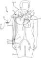
- FIG. 1 Ais a schematic view of a pump-conduit assembly of a system and method in accordance with a first embodiment of the present invention
- FIG. 1 Bis a schematic view of the pump-conduit assembly of FIG. 1 A as applied to a circulatory system of a patient in accordance with the first embodiment of the present invention
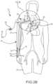
- FIG. 1 Cis a magnified view of a portion of FIG. 1 B ;
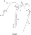
- FIG. 2 Ais a schematic view of a pump-conduit assembly of a system and method in accordance with a second embodiment of the present invention
- FIG. 2 Bis a schematic view of the pump-conduit assembly of FIG. 2 A as applied to a circulatory system of a patient in accordance with the second embodiment of the present invention
- FIG. 2 Cis a magnified view of a portion of FIG. 2 B ;
- FIG. 3is a schematic view of a pump-conduit assembly of a system and method as applied to a circulatory system of a patient in accordance with a third embodiment of the present invention
- FIG. 4 Ais a schematic view of a pump-catheter assembly of a system and method in accordance with a fourth embodiment of the present invention.
- FIG. 4 Bis a schematic view of the pump-catheter assembly of FIG. 4 A as applied to a circulatory system of a patient in accordance with the fourth embodiment of the present invention
- FIG. 5 Ais a schematic view of a pump-conduit assembly of a system and method in accordance with a fifth embodiment of the present invention.
- FIG. 5 Bis a schematic view of the pump-conduit assembly of FIG. 5 A as applied to a circulatory system of a patient in accordance with the fifth embodiment of the present invention
- FIG. 6is a schematic diagram of a pump operated in conjunction with a control unit for use in any of the above-mentioned embodiments;
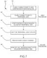
- FIG. 7is a flow chart of a method in accordance with the first and third embodiments of the present invention.
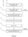
- FIG. 8is a flow chart of a method in accordance with the second and fourth embodiments of the present invention.
- FIG. 9is a flow chart of a method in accordance with the fifth embodiment of the present invention.
- FIGS. 1 - 4a system 10 to increase the overall diameter of veins is illustrated as used for a patient 20 .
- the system 10removes deoxygenated venous blood from the patient's venous system 22 and redirects that blood into the accepting peripheral vein 30 .
- the system 10also increases the speed of blood in the accepting peripheral vein 30 and increases the WSS exerted on the endothelium of the accepting peripheral vein 30 , to increase the diameter of the accepting peripheral vein 30 located, for example, in an arm 24 or a leg 26 .
- the diameter of blood vesselssuch as peripheral veins can be determined by measuring the diameter of the lumen, which is the open space at the center of blood vessel where blood is flowing. For the purpose of this application, this measurement is referred to as “lumen diameter”.
- the diameter of blood vesselscan be determined by measuring the diameter in a manner that includes the wall of the blood vessel. For the purpose of this application, this measurement is referred to as “overall diameter”.
- the inventionrelates to simultaneously and persistently increasing the overall diameter and lumen diameter of a peripheral vein by directing blood (preferably with low pulsatility) into the peripheral vein, thereby increasing the speed of the blood in the peripheral vein and increasing the WSS on the endothelium of the peripheral vein.
- bloodpreferably with low pulsatility
- Systems and methodsare described wherein the speed of the blood in a peripheral vein and the WSS on the endothelium of the peripheral vein is increased by using a pump.
- the pumpdirects blood into the peripheral vein, wherein the pumped blood has reduced pulsatility, such as when the pulse pressure is lower than blood in a peripheral artery.
- the systems and methods described hereinincrease the WSS level in a peripheral vein.
- Normal WSS for veinsranges between 0.076 Pa and 0.76 Pa.
- the systems and methods described hereinare configured to increase the WSS level in the accepting peripheral vein to range from about 0.76 Pa and 23 Pa, preferably to a range between 2.5 Pa and 7.5 Pa.
- Sustained WSS less than 0.76 Pamight dilate veins but at a rate that is comparatively slow.
- Sustained WSS greater than 23 Paare likely to cause denudation (loss) of the endothelium of the vein, which is known to retard dilation of blood vessels in response to increases in blood speed and WSS.
- the blood pumping processmay be monitored and adjusted periodically. For example, the pump may be adjusted every seven days to account for changes in the peripheral vein prior to achieving the desired persistent dilation.
- the systems and methods described hereinalso increase the speed of blood in peripheral veins and in certain instances, peripheral arteries.
- the mean speed of blood in the cephalic vein in humansis generally between 5-9 cm/s, while the speed of blood in the brachial artery is generally between 10-15 cm/s.
- the mean speed of blood in the peripheral veinis increased to a range between 15 cm/s-100 cm/s, preferably to a range between 25 cm/s and 100 cm/s, depending on the diameter of peripheral accepting vein and the length of time the pumping of blood into the peripheral accepting vein is planned.
- the mean blood speedis increased for between 7 days and 84 days, or preferably between 7 and 42 days, to induce persistent dilation in the peripheral accepting vein such that veins that were initially ineligible for use as a hemodialysis access site or bypass graft due to a small vein diameter become usable.
- Thiscan also be accomplished by intermittently increasing mean blood speed during the treatment period, with intervening periods of normal mean blood speed.
- the present inventionrelates to increasing blood speed and WSS for a period of time sufficient to result in vein remodeling and dilation.
- the systems and methods described hereinincrease the WSS level in a peripheral vein.
- Normal WSS for veinsranges between 0.076 Pa and 0.76 Pa.
- the systems and methods described hereinincrease the WSS level to a range between 0.76 Pa and 23 Pa, preferably to a range between 2.5 Pa and 7.5 Pa.
- the WSSis increased for between 7 days and 84 days, or preferably between 7 and 42 days, to induce persistent dilation in the peripheral accepting vein such that veins that were initially ineligible for use as a hemodialysis access site or bypass graft due to a small vein diameter become usable. This can also be accomplished by intermittently increasing WSS during the treatment period, with intervening periods of normal WSS.
- WSS levels in the accepting peripheral vein lower than 0.076 Pamay dilate veins however, this would likely occurs at a slow rate.
- WSS levels in accepting peripheral veins higher than about 23 Paare likely to cause denudation (loss) of the endothelium of the veins.
- Denudation of the endothelium of blood vesselsis known to retard dilation in the setting of increased in blood speed and WSS.
- the increased WSSinduces sufficient persistent dilation in the veins, such that those that were initially ineligible for use as a hemodialysis access site or bypass graft due to a small diameter become usable.
- the diameter of the accepting veincan be determined intermittently, such as every 7-14 days for example, to allow for pump speed adjustment in order to optimize vein dilation during the treatment period.
- the systems and methods described hereinalso increase the speed of blood in peripheral veins and in certain instances, peripheral arteries.
- the mean speed of blood in the cephalic vein in humansis generally between 5-9 cm/s, while the speed of blood in the brachial artery is generally between 10-15 cm/s.
- the mean speed of blood in the peripheral veinis increased to a range between 15 cm/s-100 cm/s, preferably to a range between 25 cm/s and 100 cm/s, depending on the diameter of peripheral accepting vein and the length of time the pumping of blood into the peripheral accepting vein is planned.
- the mean blood speedis increased for between 7 days and 84 days, or preferably between 7 and 42 days, to induce persistent dilation in the peripheral accepting vein such that veins that were initially ineligible for use as a hemodialysis access site or bypass graft due to a small vein diameter become usable.
- Mean blood speed levels in the accepting peripheral vein lower than 15 cm/smay dilate veins however, this would likely occurs at a slow rate.
- Mean blood velocity levels in accepting peripheral veins higher than about 100 cm/sare likely to cause denudation (loss) of the endothelium of the veins. Denudation of the endothelium of blood vessels is known to retard dilation in the setting of increased in blood speed.
- the increased mean blood speedinduces sufficient persistent dilation in the veins, such that those that were initially ineligible for use as a hemodialysis access site or bypass graft due to a small diameter become usable.
- the diameter of the accepting veincan be determined intermittently, such as every 7-14 days for example, to allow for pump speed adjustment in order to optimize vein dilation during the treatment period.
- the system 10includes a pump-conduit assembly 12 for directing deoxygenated venous blood from a donating vein 29 of the venous system 22 of the patient 20 to the peripheral or accepting vein 30 .
- the peripheral or accepting vein 30may be a cephalic vein, radial vein, median vein, ulnar vein, antecubital vein, median cephalic vein, median basilic vein, basilic vein, brachial vein, lesser saphenous vein, greater saphenous vein, or femoral vein.
- Other veinsthat might be useful in the creation of a hemodialysis access site or bypass graft or other veins useful for other vascular surgery procedures requiring the use of veins may be used.
- the pump-conduit assembly 12delivers the deoxygenated blood to the peripheral or accepting vein 30 .
- the rapid speed of the blood 34 and the elevated WSS in the peripheral vein 30causes the peripheral or accepting vein 30 to enlarge over time.
- the system 10 and method 100(referring to FIGS. 7 - 9 ) of the present invention advantageously increases the diameter of the peripheral or accepting vein 30 so that it can be used, for example, to construct an AVF or AVG access site for hemodialysis or as a bypass graft.
- deoxygenated bloodis blood that has passed through the capillary system and had oxygen removed by the surrounding tissues and then passed into the venous system 22 .
- a peripheral vein 30means any vein with a portion residing outside of the chest, abdomen, or pelvis. In the embodiment shown in FIGS. 1 A and 2 A , the peripheral or accepting vein 30 is the cephalic vein. However, in other embodiments, the peripheral vein 30 may be a radial vein, median vein, ulnar vein, antecubital vein, median cephalic vein, median basilic vein, basilic vein, brachial vein, lesser saphenous vein, greater saphenous vein, or femoral vein.
- veinsthat might be useful in the creation of a hemodialysis access site or bypass graft or other veins useful for other vascular surgery procedures requiring the use of veins may also be used, such as those residing in the chest, abdomen, and pelvis.
- pulsatility dampening techniquesinclude tuning the head-flow characteristics of a blood pump, adding compliance to the pump outflow, and/or modulating the pump speed.
- An AVF created using the cephalic vein at the wristis a preferred form of vascular access for hemodialysis but this vein is frequently of inadequate diameter to facilitate the creation of an AVF in this location.
- the present inventionis most advantageous to creating wrist AVFs in ESRD patients and increasing the percentage of ESRD patients that receive hemodialysis using a wrist AVF as a vascular access site.
- the pump-conduit assembly 12includes a blood pump 14 and synthetic conduits 16 and 18 , i.e. an inflow conduit 16 and an outflow conduit 18 .
- Blood pumpshave been developed as a component of ventricular assist devices (VADs) and have been miniaturized to treat both adult patients with moderate heart failure and pediatric patients. These pumps can be implanted or remain external to the patient and are usually connected to a controller and a power source. Referring to FIG. 6 , a schematic diagram of the pump-conduit assembly 12 is illustrated.
- the pump 14can be a rotary pump such as an axial, mixed flow, or centrifugal pump.
- the bearing for the pump 14can be constructed with magnetic fields, with hydrodynamic forces, or using a mechanical contact bearing such as a double-pin bearing. Pumps used in pediatric VAD systems or other low flow VAD systems can be used.
- the pump 14can be an extracardiac pump such as that shown and described in U.S. Pat. Nos. 6,015,272 and 6,244,835, both of which are hereby incorporated herein by reference. These pumps are suitable for use in the system 10 and method 100 of the present invention.
- the pump 14has an inlet 38 to receive deoxygenated blood drawn through the inflow conduit 16 and an outlet 40 for blood flow 34 to exit the pump 14 .
- these pumpscan be sized as small as about the size of a AA battery or the diameter of a United States half dollar or quarter, and can weigh as little as about 25-35 g or less. These pumps are designed to pump about 0.3 to 1.5 L/min or 1 to 2.5 L/min, for example. Modifications to these pumps could be made to reduce this range to as low as 0.05 L/min for use in small diameter veins.
- a priming volumecan be about 0.5-0.6 ml, for example.
- the blood-contacting surfaces of the pump 14preferably include Ti6Al4V and commercially pure titanium alloys and can include other materials such as injection-moldable ceramics and polymers, and alternative titanium alloys, e.g. Ti6Al7Nb.
- the blood-contacting surfacealso preferably has one or more coatings and surface treatments. As such, any of a variety of pumping devices can be used so long as it can be connected to the vascular system and can pump a sufficient amount of blood such that the desired WSS is achieved in the accepting vein.
- the pump 14includes various components 42 and a motor 44 , as shown in FIG. 6 .
- the various components 42 and motor 44can be those common to a VAD.
- the components 42include one or more of a shaft, impeller blades, bearings, stator vanes, rotor, or stator.
- the rotorcan be magnetically levitated.
- the motor 44can include a stator, rotor, coil, and magnets.
- the motor 44may be any suitable electric motor, such as a multi-phase motor controlled via pulse-width modulated current.
- the system 10 and method 100can utilize one or more of the pumps described in the following publications: The PediaFlowTM Pediatric Ventricular Assist Device, P. Wearden, et al., Pediatric Cardiac Surgery Annual, pp. 92-98, 2006; J. Wu et al., Designing with Heart, ANSYS Advantage, Vol. 1, Iss. 2, pp. s12-s13, 2007; and J. Baldwin, et al., The National Heart, Lung, and Blood Institute Pediatric Circulatory Support Program, Circulation, Vol. 113, pp. 147-155, 2006.
- pumpsthat can be used as the pump 14 include: the Novacor, PediaFlow, Levacor, or MiVAD from World Heart, Inc.; the Debakey Heart Assist 1-5 from Micromed, Inc.; the HeartMate XVE, HeartMate II, HeartMate III, IVAD, or PVAD from Thoratec, Inc.; the Impella, BVS5000, AB5000, or Symphony from Abiomed, Inc.; the TandemHeart from CardiacAssist, Inc.; the VentrAssist from Ventracor, Inc.; the Incor or Excor from Berlin Heart, GmbH; the Duraheart from Terumo, Inc.; the HVAD or MVAD from HeartWare, Inc.; the Jarvik 2000 Flowmaker or Pediatric Jarvik 2000 Flowmaker from Jarvik Heart, Inc.; the Gyro C1E3 from Kyocera, Inc.; the CorAide or PediPump from the Cleveland Clinic Foundation; the MEDOS HIA VAD from MEDOS Medizintechnik AG
- the pumpscan be monitored and adjusted manually or with a software program , application, or other automated system.
- the software programcan automatically adjust the pump speed to maintain the desired amount of blood flow and WSS in the accepting vein.
- the vein diameter and blood flowmay be periodically checked manually and the pump may be manually adjusted, for example, by tuning the head-flow characteristics of the pump, adding compliance to the pump outflow, and/or modulating the pump speed. Other adjustments may also be made.
- the synthetic conduits 16 and 18are comprised of PTFE and/or Dacron, preferentially reinforced so that the synthetic conduits 16 and 18 are less susceptible to kinking and obstruction. All or a portion of the conduits 16 and 18 may be comprised of materials commonly used to make hemodialysis catheters such as polyvinyl chloride, polyethylene, polyurethane, and/or silicone.
- the synthetic conduits 16 and 18can be of any material or combination of materials so long as the conduits 16 and 18 exhibit necessary characteristics, such as flexibility, sterility, resistance to kinking, and can be connected to a blood vessel via an anastomosis or inserted into the lumen of a blood vessel, as needed.
- the synthetic conduits 16 and 18preferably exhibit the characteristics needed for tunneling (as necessary) and have luminal surfaces that are resistant to thrombosis.
- the synthetic conduits 16 and 18can have an exterior layer composed of a different material than the luminal layer.
- the synthetic conduits 16 and 18can also be coated with silicon to aid in removal from the body and avoid latex allergies.
- the connection between the synthetic conduit 16 or 18 and the vein 29 or 30is made using a conventional surgical anastomosis, using suture in a running or divided fashion, henceforth described as an “anastomotic connection.”
- An anastomotic connectioncan also be made with surgical clips and other standard ways of making an anastomosis.
- the synthetic inflow conduit 16has a first end 46 configured to fluidly connect to a donating vein 29 or the right atrium 31 of the heart and a second end 48 connected to the inlet 38 of the pump 14 .
- the donating vein 29can include an antecubital vein, basilic vein, brachial vein, axillary vein, subclavian vein, jugular vein, brachiocephalic vein, superior vena cava, lesser saphenous vein, greater saphenous vein, femoral vein, common iliac vein, external iliac vein, superior vena cava, inferior vena cava, or other veins capable of providing sufficient blood flow to the pump for the purpose of causing persistent dilation of the accepting peripheral vein.
- the synthetic outflow conduit 18has a first end 52 configured to fluidly connect to the peripheral accepting vein 30 and a second end 54 connected to the outlet 40 of the pump 14 .
- the pump-conduit assembly 12is configured to redirect blood from the donating vein 29 to the peripheral accepting vein 30 in a manner that increases the blood speed and WSS in the peripheral vein to the desired level for a period of time sufficient to cause a persistent increase in the overall diameter and lumen diameter of the peripheral vein.
- a portion of the synthetic conduits 16 , 18may be extracorporeal to the patient 20 .
- the first end 46 of the inflow conduit 16 and the first end 52 of the outflow conduit 18are configured for an anastomotic connection. As shown in FIGS.
- the first end 46is fluidly connected to the internal jugular vein (which serves as the donating vein 29 ) via an anastomotic connection and the first end 52 of the outflow conduit 18 is fluidly connected to the cephalic vein (which serves as the peripheral accepting vein 30 ) via an anastomotic connection.
- the first end 46 of the synthetic inflow conduit 16is configured as a catheter.
- the fluid connection between the synthetic inflow conduit 16 and the venous systemis made by positioning the tip of the catheter portion 50 of the synthetic inflow conduit into the superior vena cava 27 , henceforth described as a “catheter connection”.
- a catheter connectionis made with a donating vein 29 (in this case, the superior vena cava 27 )
- the catheter portion 50 of the synthetic inflow conduit 46may enter the venous system at any location where the vein lumen diameter is adequate to accept the catheter portion 50 .
- the tip of the catheter portion 50may be placed at any location where sufficient blood can be drawn into the catheter to provide the desired blood flow 34 to the accepting vein 30 .
- Preferred locations for the tip of the catheter portion 50include, but are not limited to a brachiocephalic vein, the superior vena cava 27 , and the right atrium 31 .
- the system 10draws deoxygenated blood from the superior vena cava 27 of the patient 20 and redirects it to the cephalic vein 30 in the arm 24 .
- the system 10redirects deoxygenated venous blood from donating vein 29 (in this case, the more central portion of the greater saphenous vein) to the peripheral accepting vein 30 (in this case, a more peripheral portion of the greater saphenous vein) in the leg 26 thereby increasing the speed of blood and WSS in the accepting vein to the desired level and for a period of time sufficient to cause a persistent increase in the lumen diameter and overall diameter of the accepting greater saphenous vein 30 .
- the inflow conduit 16is fluidly connected to a greater saphenous vein 29 of the patient 20 via an anastomotic connection.
- the bloodis pumped into the accepting vein with a pulsatility that is reduced when compared with the pulsatility of blood in a peripheral artery.
- the mean pulse pressure in the accepting vein adjacent to the connection with the outflow conduitis ⁇ 40 mmHg, ⁇ 30 mmHg, ⁇ 20 mmHg, ⁇ 10 mmHg, or preferably ⁇ 5 mmHg with the pump operating.
- the pumping of blood into the peripheral vein and the increase in blood speed and WSScontinues for a period of time sufficient to cause a persistent increase in the overall diameter and lumen diameter of the accepting greater saphenous vein segment 30 to facilitate extraction and autotransplantation as part of a surgery to create a cardiac or peripheral bypass graft, or other surgery that requires autotransplantation of a portion of a patient's vein.
- an extracorporeal pump 114is attached to two specialized catheters, an inflow catheter 55 , and an outflow catheter 56 to form a catheter-pump assembly 13 .
- the pump 114draws deoxygenated blood into the lumen of the inflow catheter 55 from the donating vein 29 and then discharges the blood from the outflow catheter 56 and into the lumen of the peripheral accepting vein 30 , thereby increasing the speed of blood and the WSS in the peripheral accepting vein 30 .
- FIGS. 4 A and 4 Billustrate another embodiment of the system 10 .
- the pump-catheter assembly 13is configured to increase the blood speed and WSS in vein segment d.
- the inflow catheter 55 and the outflow catheter 56may optionally be joined in all or some portions (such as with a double lumen catheter) and can be percutaneously inserted into the lumen of the accepting peripheral vein 30 , obviating the need for an invasive surgical procedure.
- a portion of the cathetercan be tunneled subcutaneously before exiting the skin in order to reduce the risk of infection.
- Extracorporeal portions of the catheters 119 and 120 and the extracorporeal pump 114can be affixed to the body, connected to a power source, and operated in a manner that increases the speed of the blood 34 and WSS in segment d of the accepting peripheral vein 30 for a period of time sufficient to cause a persistent increase the overall diameter and lumen diameter of segment d of the accepting peripheral vein 30 .
- the pump-catheter assembly 12is removed and a surgical procedure can be performed to create a hemodialysis access site or bypass graft using at least a portion of the enlarged segment d of the accepting peripheral vein 30 , either at the same time or in a subsequent operation.
- a system 10 to increase the overall diameter of veinsis illustrated as used for a patient 20 .
- the system 10removes oxygenated arterial blood from a patient's peripheral artery 221 and redirects that blood into the accepting peripheral vein 30 and is configured and operated to increase the blood speed and WSS in the accepting peripheral vein 30 for a period of time sufficient to cause a persistent increase in the diameter of the accepting peripheral vein 30 in, for example, an arm 24 or a leg 26 .
- An embodiment of a system 10 in which a pump 214 is implanted in the arm 24is illustrated.
- the pump 214has an inlet 216 connected to an artery 221 in the arm 24 via anastomotic connection.
- the pump 214also has an outlet 218 connected to the peripheral vein 30 via an anastomotic connection.
- the pump 214is controlled and powered by the control unit 58 .
- the pump 214withdraws blood from the artery 221 and pumps the blood into the peripheral vein 30 .
- This embodimentcan allow the performance of a surgical procedure that avoids the need for extended synthetic conduits and increases blood speed and WSS in both the peripheral vein 30 and the peripheral artery 221 resulting in, if operated for a sufficient period of time, simultaneous dilation of the vein 30 and the artery 221 .
- the pump 214is implanted in the forearm of the patient 20 .
- the pump 214can be removed and a surgical procedure can be performed to create a hemodialysis access site or bypass graft using at least a portion the enlarged artery 221 or vein 30 , either at that time or during a subsequent operation.
- oxygenated arterial bloodmay be drawn from a donating artery.
- Donating arteriesmay include, but are not limited to, a radial artery, ulnar artery, interosseous artery, brachial artery, anterior tibial artery, posterior tibial artery, peroneal artery, popliteal artery, profunda artery, superficial femoral artery, or femoral artery.
- the control unit 58is connected to the pump 14 and is configured to control the speed of the pump 14 and collect information on the function of the pump 14 .
- the control unit 58may be implanted in the patient 20 , may remain external to the patient 20 , or may have implanted and external portions.
- a power sourceis embodied in a power unit 60 and is connected to the control unit 58 and the pump 14 .
- the power unit 60provides energy to the pump 14 and the control unit 58 for routine operation.
- the power unit 60may be implanted in the patient 20 , may remain external to the patient 20 , or may have implanted and external portions.
- the power unit 60may include a battery 61 .
- the battery 61is preferably rechargeable and is recharged via a connector 69 to an AC source. Such rechargeable batteries could also be recharged using lead wires or via transcutaneous energy transmission.
- the connector 69may deliver electrical power to the power unit 60 without the aid of the battery 61 . It will be apparent to one of ordinary skill in the art from this disclosure that the control unit 58 can be configured to utilize alternative power-control systems.
- Sensors 66 and 67may be incorporated into the synthetic conduits 17 and 18 , the pump 14 , or the control unit 58 .
- the sensors 66 and 67are connected to the control unit 58 via cable 68 or can wirelessly communicate with the control unit 58 .
- the sensors 66 and 67can monitor blood flow, blood speed, intraluminal pressure, and resistance to flow and may send signals to the control unit 58 to alter pump speed. For example, as the peripheral vein 30 receiving the pumped blood dilates, blood speed in the vein decreases, along with resistance to blood flow 34 from the outflow conduit 18 . In order to maintain the desired blood speed and WSS, the pump speed must be adjusted as the peripheral vein 30 dilates over time.
- the sensors 66 and 67may sense blood speed in the peripheral vein 30 or resistance to blood flow and then signal the control unit 58 which then increases the speed of the pump 14 accordingly.
- the present inventionadvantageously provides a monitoring system, constituted by the control unit 58 and sensors 66 and 67 , to adjust the pump speed to maintain the desired blood speed and WSS in the accepting peripheral vein 30 as it dilates over time.
- the control unitmay rely on a measurement, including an internal measurement of the electrical current to the motor 44 as a basis for estimating blood flow, blood speed, intraluminal pressure, or resistance to flow, thus obviating the need for sensors 66 and 67 .
- the control unit 58may also include manual controls to adjust pump speed or other pumping parameters.
- the control unit 58is operatively connected to the pump-conduit assembly 12 . Specifically, the control unit 58 is operatively connected to the pump 14 by one or more cables 62 . Utilizing the power unit 60 , the control unit 58 preferably supplies pump motor control current, such as pulse width modulated motor control current to the pump 14 via cable 62 . The control unit 58 can also receive feedback or other signals from the pump 14 .
- the control unit 58further includes a communication unit 64 that is utilized to collect data and communicate the data, via telemetric transmission, for example. Furthermore, the communication unit 64 is configured to receive instructions or data for reprogramming the control unit 58 . Therefore, the communication unit 64 is configured to receive instructions or data for controlling the pump 14 .
- the present inventionadvantageously provides a monitoring system, constituted by the control unit 58 and sensors 66 and 67 , to adjust the operation of the pump to maintain the desired blood speed and WSS in the accepting peripheral vein 30 as it dilates over time.
- the pump 14is configured to provide a blood flow 34 in a range from about 50-1500 mL/min, for example, and increase the WSS in an accepting peripheral vein to a range of between 0.76 Pa and 23 Pa, preferably to a range between 2.5 Pa and 7.5 Pa.
- the pump 14is configured to maintain the desired level of blood flow and WSS in the accepting peripheral vein 30 for a period of about 7-84 days, for example, and preferably about 14-42 days, for example. In certain situations where a large amount of vein dilation is desired or where vein dilation occurs slowly, the pump 14 is configured to maintain the desired level of blood flow and WSS in the accepting peripheral vein 30 for longer than 42 days.
- the pump-conduit assembly 12can be implanted on the right side of the patient 20 , or can be implanted on the left side, as need be.
- the lengths of the conduits 16 and 18can be adjusted for the desired placement.
- the first end 46 of the inflow conduit 16is fluidly connected to the location 29 in the right internal jugular vein 29 and the first end 52 of the outflow conduit 18 is fluidly connected to the cephalic vein 30 in the right forearm.
- FIGS. 1 B and 1 Cthe first end 46 of the inflow conduit 16 is fluidly connected to the location 29 in the right internal jugular vein 29 and the first end 52 of the outflow conduit 18 is fluidly connected to the cephalic vein 30 in the right forearm.
- the first end 46 of the inflow conduit 16is fluidly connected to the location 29 in the superior vena cava 27 and the first end 52 of the outflow conduit 18 is fluidly connected to the cephalic vein 30 in the right forearm 24 .
- pumpingis started. That is, the control unit 58 begins to operate the motor 44 .
- the pump 14pumps blood 34 through the outlet conduit 18 and into the peripheral vein 30 .
- the control unit 58adjusts pumping over the course of time by utilizing data provided by the sensors 66 and 67 .
- FIGS. 1 - 4illustrate examples in which the system 10 pumps deoxygenated blood.
- FIG. 5illustrates an example in which the system 10 pumps oxygenated blood.
- the bloodis pumped into the accepting vein with a pulsatility that is reduced when compared with the pulsatility of blood in a peripheral artery.
- the mean pulse pressure in the accepting veinis ⁇ 40 mmHg, ⁇ 30 mmHg, ⁇ 20 mmHg, ⁇ 10 mmHg, or preferably ⁇ 5 mmHg with the pump operating and delivering blood into the peripheral vein.
- the bloodis pumped into the accepting vein with a pulsatility that is equal to or increased when compared with the pulsatility of blood in a peripheral artery.
- the mean pulse pressure in the accepting vein adjacent to the connection with the outflow conduitis >40 mmHg with the pump operating.
- the donating vein 29is a jugular vein 21 , preferentially an internal jugular vein 21 .
- the internal jugular vein 21is particularly useful as a donating vein 29 due to the absence of valves between the internal jugular vein 21 and the right atrium 31 , which would allow the synthetic inflow conduit 16 to be able to draw a large volume of deoxygenated blood per unit time.
- the inflow conduit 18is fluidly connected to the internal jugular vein 21 of the patient 20 . Deoxygenated blood is drawn from the internal jugular vein 21 and pumped into the peripheral accepting vein 30 in the arm 24 or leg 26 resulting in an increase in the speed of blood 34 and WSS in the peripheral accepting vein.
- the bloodis pumped into the accepting vein with a pulsatility that is reduced when compared with the pulsatility of blood in a peripheral artery.
- the mean pulse pressure in the accepting vein adjacent to the connection with the outflow conduitis ⁇ 40 mmHg, ⁇ 30 mmHg, ⁇ 20 mmHg, ⁇ 10 mmHg, or preferably ⁇ 5 mmHg with the pump operating.
- FIG. 5 Billustrates an example in which the system 10 draws oxygenated blood.
- the inflow conduit 216is fluidly connected to the radial artery 221 of the patient 20 and the outflow conduit 218 is fluidly connected to the cephalic vein, both using an anastomotic connection.
- oxygenated bloodis drawn from the radial artery 221 and pumped into the cephalic vein 30 in the arm 24 in a manner that results in an increased blood speed and WSS in the cephalic vein for a sufficient period of time to cause a persistent increase in the overall diameter and lumen diameter of the accepting peripheral vein.
- the bloodis pumped into the accepting vein with a pulsatility that is reduced when compared with the pulsatility of blood in a peripheral artery.
- the mean pulse pressure in the accepting vein adjacent to the connection with the outflow conduitis ⁇ 40 mmHg, ⁇ 30 mmHg, ⁇ 20 mmHg, ⁇ 10 mmHg, or preferably ⁇ 5 mmHg with the pump operating and delivering blood into the peripheral accepting vein.
- various embodiments of the method 100increase the overall diameter and the lumen diameter of the peripheral vein 30 .
- a physician or surgeonperforms a procedure to access a vein or artery and connects a pump to establish fluid communication with a vein carrying deoxygenated blood at step 101 .
- the pumpis connected to a peripheral vein.
- the pump-conduit assembly 12is preferably implanted in the neck, chest and the arm 24 of the patient 20 .
- the peripheral vein 30is the saphenous vein 36
- the pump-conduit assembly 12is implanted in the leg 26 .
- the physicianfluidly connects the first end 46 of the pump-conduit assembly 12 to the donating vein 29 and the second end of the pump-conduit assembly 12 to the peripheral accepting vein 30 , utilizing a tunneling procedure (as necessary) to connect the two locations subcutaneously.
- the deoxygenated bloodis pumped into the peripheral accepting vein.
- the pumpingcontinues for a period of time, while the physician waits for the peripheral accepting vein to dilate. In one embodiment, after the pump is turned on to start the pumping of deoxygenated blood, the skin incisions are closed, as necessary.
- portions of the synthetic conduits 16 and 18 and/or the pump 14are extracorporeally located.
- the pump 14is then started and controlled via the control unit 58 to pump the deoxygenated blood through the pump-conduit assembly 12 and into the peripheral accepting vein 30 in a manner that increases the blood speed and WSS in the peripheral vein 30 .
- the pumping processis monitored periodically and the control unit 58 is used to adjust the pump 14 , in response to changes in the peripheral accepting vein 30 . With periodic adjustments, as necessary, the pump continues to operate for an amount of time sufficient to result in the persistent dilation of the overall diameter and lumen diameter of the peripheral vein 30 .
- the pump-conduit assembly 12is disconnected and removed at step 105 .
- the persistently dilated peripheral vein 30is used to create an AVF, AVG, or bypass graft.
- the physician or surgeoninserts one or more catheter portions 50 of the pump-catheter assembly into the venous system and positions them in a donating vessel and a peripheral vein 30 at step 107 .
- the pumpis operated to pump deoxygenated blood into the deoxygenated blood.
- the physicianthen waits for the peripheral vessel to dilate at step 109 .
- the pump-catheter assemblyis removed and the persistently dilated vein is used to create an AVF, AVG, or bypass graft, at steps 110 and 111 , respectively.
- FIG. 9shows, yet another embodiment of the method 100 .
- a physician or surgeonperforms a procedure to access a vein and connects a pump to establish fluid communication with a peripheral vein.
- the pumpis connected to a peripheral artery.
- the pumpis operated, at step 114 to pump oxygenated blood from the peripheral artery to the peripheral vein.
- the pumpingcontinues for a period of time, while the physician waits for the peripheral vein dilate.
- the pumpis removed and at step 117 , the persistently dilated vein is used to create an AVF, AVG, or bypass graft.
- the method 100 and/or the system 10may be used to in periodic and/or intermittent sessions, as opposed to continuous treatment.
- hemodialysis treatmentsthat may last from 3 to 5 hours are given in a dialysis facility up to 3 times a week. Therefore, various embodiments of the system 10 and method 100 may be used to provide blood pumping treatments on a similar schedule over a 4 to 6 week period. The treatments may be performed in any suitable location, including in an outpatient setting.
- the blood pumping treatmentis done intermittently in conjunction with hemodialysis treatments.
- a low-flow pumpe.g. catheter-based VADs and pediatric cardiopulmonary bypass (CPB) or extracorporeal membrane oxygenation (ECMO) pumps
- CPBpediatric cardiopulmonary bypass
- ECMOextracorporeal membrane oxygenation
- the access to the blood vesselsmay also occur through one or more ports or surgically created access sites.
- the accessmay be achieved through a needle, a peripherally inserted central catheter, a tunneled catheter, a non-tunneled catheter, and/or a subcutaneous implantable port.
- a low-flow pumpis used to increase WSS and blood speed in a blood vessel.
- the low-flow pumphas an inlet conduit fluidly connected to a blood vessel and an outlet conduit fluidly connected to a vein pumps blood from the blood vessel to the vein for a period between about 7 days and 84 day.
- the low-flow pumppumps blood such that the wall shear stress of the vein ranges between about 0.076 Pa to about 23 Pa.
- the low-flow pumpalso includes an adjustment device.
- the adjustment devicemay be in communication with a software-based automatic adjustment system or the adjustment device may have manual controls.
- the inlet conduit and the outlet conduitmay range in length from about 10 centimeters to about 107 centimeters.
- the present inventionalso relates to a method of assembling and operating a blood pump system, including various embodiments of the pump-conduit system 10 .
- the methodincludes attaching a first conduit in fluid communication with the pump-conduit system 10 to an artery and attaching a second conduit in fluid communication with the pump-conduit system to a vein.
- the pump-conduit system 10is then activated to pump blood between the artery and the vein.
- the term “comprising” and its derivatives, as used herein,are intended to be open ended terms that specify the presence of the stated features, elements, components, groups, integers, and/or steps, but do not exclude the presence of other unstated features, elements, components, groups, integers and/or steps.
- the foregoingalso applies to words having similar meanings such as the terms, “including”, “having”, and their derivatives.
- the terms of degree such as “substantially”, “about” and “approximate” as used hereinmean a reasonable amount of deviation of the modified term such that the end result is not significantly changed. For example, these terms can be construed as including a deviation of at least ⁇ 5% of the modified term if this deviation would not negate the meaning of the word it modifies.
Landscapes
- Health & Medical Sciences (AREA)
- Heart & Thoracic Surgery (AREA)
- Engineering & Computer Science (AREA)
- Life Sciences & Earth Sciences (AREA)
- Cardiology (AREA)
- Veterinary Medicine (AREA)
- General Health & Medical Sciences (AREA)
- Biomedical Technology (AREA)
- Public Health (AREA)
- Animal Behavior & Ethology (AREA)
- Hematology (AREA)
- Anesthesiology (AREA)
- Mechanical Engineering (AREA)
- Vascular Medicine (AREA)
- Surgery (AREA)
- Urology & Nephrology (AREA)
- Physics & Mathematics (AREA)
- Optics & Photonics (AREA)
- Medical Informatics (AREA)
- Nuclear Medicine, Radiotherapy & Molecular Imaging (AREA)
- Molecular Biology (AREA)
- Pathology (AREA)
- Biophysics (AREA)
- Pulmonology (AREA)
- Oral & Maxillofacial Surgery (AREA)
- Emergency Medicine (AREA)
- External Artificial Organs (AREA)
- Surgical Instruments (AREA)
Abstract
Description
WSS(τ)=4Qμ/πR3, where:
WSS(τ)=4Qμ/πR3, where:
Claims (19)
Priority Applications (1)
| Application Number | Priority Date | Filing Date | Title |
|---|---|---|---|
| US16/748,639US11724018B2 (en) | 2010-02-17 | 2020-01-21 | System and method to increase the overall diameter of veins |
Applications Claiming Priority (4)
| Application Number | Priority Date | Filing Date | Title |
|---|---|---|---|
| US30550810P | 2010-02-17 | 2010-02-17 | |
| US13/030,054US9155827B2 (en) | 2010-02-17 | 2011-02-17 | System and method to increase the overall diameter of veins |
| US14/881,054US10537674B2 (en) | 2010-02-17 | 2015-10-12 | System and method to increase the overall diameter of veins |
| US16/748,639US11724018B2 (en) | 2010-02-17 | 2020-01-21 | System and method to increase the overall diameter of veins |
Related Parent Applications (1)
| Application Number | Title | Priority Date | Filing Date |
|---|---|---|---|
| US14/881,054DivisionUS10537674B2 (en) | 2010-02-17 | 2015-10-12 | System and method to increase the overall diameter of veins |
Publications (2)
| Publication Number | Publication Date |
|---|---|
| US20200155752A1 US20200155752A1 (en) | 2020-05-21 |
| US11724018B2true US11724018B2 (en) | 2023-08-15 |
Family
ID=44370149
Family Applications (5)
| Application Number | Title | Priority Date | Filing Date |
|---|---|---|---|
| US13/030,054ActiveUS9155827B2 (en) | 2010-02-17 | 2011-02-17 | System and method to increase the overall diameter of veins |
| US14/881,054Active2033-11-16US10537674B2 (en) | 2010-02-17 | 2015-10-12 | System and method to increase the overall diameter of veins |
| US14/881,046Active2033-03-27US10293089B2 (en) | 2010-02-17 | 2015-10-12 | System and method to increase the overall diameter of veins |
| US15/402,050Active2031-07-27US10376629B2 (en) | 2010-02-17 | 2017-01-09 | Methods to increase the overall diameter of donating veins and arteries |
| US16/748,639Active2032-12-06US11724018B2 (en) | 2010-02-17 | 2020-01-21 | System and method to increase the overall diameter of veins |
Family Applications Before (4)
| Application Number | Title | Priority Date | Filing Date |
|---|---|---|---|
| US13/030,054ActiveUS9155827B2 (en) | 2010-02-17 | 2011-02-17 | System and method to increase the overall diameter of veins |
| US14/881,054Active2033-11-16US10537674B2 (en) | 2010-02-17 | 2015-10-12 | System and method to increase the overall diameter of veins |
| US14/881,046Active2033-03-27US10293089B2 (en) | 2010-02-17 | 2015-10-12 | System and method to increase the overall diameter of veins |
| US15/402,050Active2031-07-27US10376629B2 (en) | 2010-02-17 | 2017-01-09 | Methods to increase the overall diameter of donating veins and arteries |
Country Status (12)
| Country | Link |
|---|---|
| US (5) | US9155827B2 (en) |
| EP (1) | EP2536465B1 (en) |
| JP (3) | JP2013519497A (en) |
| KR (3) | KR101845213B1 (en) |
| CN (2) | CN103495219B (en) |
| AU (1) | AU2011217974B2 (en) |
| BR (1) | BR112012020614B1 (en) |
| CA (1) | CA2790194C (en) |
| ES (1) | ES2681744T3 (en) |
| IL (2) | IL221503A (en) |
| RU (1) | RU2741571C2 (en) |
| WO (1) | WO2011103356A1 (en) |
Families Citing this family (56)
| Publication number | Priority date | Publication date | Assignee | Title |
|---|---|---|---|---|
| US9555174B2 (en) | 2010-02-17 | 2017-01-31 | Flow Forward Medical, Inc. | Blood pump systems and methods |
| US9662431B2 (en) | 2010-02-17 | 2017-05-30 | Flow Forward Medical, Inc. | Blood pump systems and methods |
| KR101845213B1 (en) | 2010-02-17 | 2018-05-18 | 플로우 포워드 메디컬, 인크. | System and method to increase the overall diameter of veins |
| EP4032486A1 (en) | 2010-11-16 | 2022-07-27 | TVA Medical, Inc. | Devices for forming a fistula |
| KR102062132B1 (en)* | 2011-08-17 | 2020-01-03 | 플로우 포워드 메디컬, 인크. | Blood pump systems and methods |
| EP2744539B1 (en) | 2011-08-17 | 2022-11-02 | Artio Medical, Inc. | System to increase the overall diameter of a peripheral artery |
| US8663116B2 (en)* | 2012-01-11 | 2014-03-04 | Angiodynamics, Inc. | Methods, assemblies, and devices for positioning a catheter tip using an ultrasonic imaging system |
| DE102012007412B4 (en)* | 2012-04-16 | 2023-09-28 | Fresenius Medical Care Deutschland Gmbh | Methods and devices for modulating the operating point of liquid pumps in medical treatment devices |
| JP6338575B2 (en) | 2012-05-21 | 2018-06-06 | ユニバーシティ・オブ・シンシナティ | Method for making a magnesium biodegradable stent for medical implant applications |
| EP4252823A3 (en)* | 2012-08-15 | 2023-11-15 | Artio Medical, Inc. | Blood pump systems and methods |
| US10258730B2 (en) | 2012-08-17 | 2019-04-16 | Flow Forward Medical, Inc. | Blood pump systems and methods |
| US9486276B2 (en) | 2012-10-11 | 2016-11-08 | Tva Medical, Inc. | Devices and methods for fistula formation |
| KR20150126877A (en)* | 2013-03-07 | 2015-11-13 | 서클라이트, 인크. | Transseptal cannula, tip, delivery system, and method |
| CN105228683B (en) | 2013-03-14 | 2022-06-10 | Tva医疗公司 | Fistula-forming device and method for forming fistula |
| US10188831B2 (en) | 2013-03-14 | 2019-01-29 | Angiodynamics, Inc. | Systems and methods for catheter tip placement using ECG |
| US20150238671A1 (en)* | 2014-02-24 | 2015-08-27 | Bravo Biomed | Blood flow management methods and systems |
| US10695534B2 (en) | 2014-03-14 | 2020-06-30 | Tva Medical, Inc. | Fistula formation devices and methods therefor |
| US20150282734A1 (en) | 2014-04-08 | 2015-10-08 | Timothy Schweikert | Medical device placement system and a method for its use |
| WO2016033374A1 (en) | 2014-08-27 | 2016-03-03 | Tva Medical, Inc. | Cryolipopysis devices and methods therefor |
| US10603040B1 (en) | 2015-02-09 | 2020-03-31 | Tva Medical, Inc. | Methods for treating hypertension and reducing blood pressure with formation of fistula |
| CN107405083B (en) | 2015-02-12 | 2020-11-03 | 方德里创新研究第一有限公司 | Implantable devices for heart failure monitoring and related methods |
| EP3331426B1 (en) | 2015-08-03 | 2024-07-24 | Foundry Innovation&Research 1, Ltd. | Catheter for measurement of vena cava dimension |
| DK3324867T3 (en)* | 2015-12-02 | 2019-08-05 | Neurescue Aps | Device for emergency treatment of cardiac arrest |
| CN105310779B (en)* | 2015-12-03 | 2018-08-07 | 北京大学人民医院 | A kind of complete expansionary kit of crowd's arteria brachialis of auxiliary judgment |
| WO2017124062A1 (en) | 2016-01-15 | 2017-07-20 | Tva Medical, Inc. | Devices and methods for forming a fistula |
| JP7219090B2 (en) | 2016-01-15 | 2023-02-07 | ティーブイエー メディカル, インコーポレイテッド | Systems and methods for gluing vessels |
| US10874422B2 (en) | 2016-01-15 | 2020-12-29 | Tva Medical, Inc. | Systems and methods for increasing blood flow |
| CN114042224B (en) | 2016-01-15 | 2024-09-17 | Tva医疗公司 | Device and method for advancing a wire |
| AU2017257508B2 (en) | 2016-04-29 | 2021-10-14 | Artio Medical, Inc. | Conduit tips and systems and methods for use |
| US11206992B2 (en) | 2016-08-11 | 2021-12-28 | Foundry Innovation & Research 1, Ltd. | Wireless resonant circuit and variable inductance vascular monitoring implants and anchoring structures therefore |
| US11701018B2 (en) | 2016-08-11 | 2023-07-18 | Foundry Innovation & Research 1, Ltd. | Wireless resonant circuit and variable inductance vascular monitoring implants and anchoring structures therefore |
| EP3496606A1 (en) | 2016-08-11 | 2019-06-19 | Foundry Innovation & Research 1, Ltd. | Systems and methods for patient fluid management |
| CN109982652B (en) | 2016-09-25 | 2022-08-05 | Tva医疗公司 | Vascular stent device and method |
| JP7241405B2 (en) | 2016-11-29 | 2023-03-17 | ファウンドリー イノベーション アンド リサーチ 1,リミテッド | Wireless resonant circuit and variable inductance vascular implant for monitoring vascular and fluid status in patients, and systems and methods utilizing same |
| US11944495B2 (en) | 2017-05-31 | 2024-04-02 | Foundry Innovation & Research 1, Ltd. | Implantable ultrasonic vascular sensor |
| EP3629921B1 (en) | 2017-05-31 | 2025-04-02 | Foundry Innovation & Research 1, Ltd. | Implantable sensors for vascular monitoring |
| DE102017112437A1 (en)* | 2017-06-06 | 2018-12-06 | Rheinisch-Westfälische Technische Hochschule (Rwth) Aachen | Cardiac assist system, needle assembly for a cardiac assist system and use of the cardiac assist system |
| DE102017210888A1 (en)* | 2017-06-28 | 2019-01-03 | Robert Bosch Gmbh | A delivery channel for a cardiac assist system, cardiac assistance system, and method and apparatus for establishing a delivery conduit for a cardiac assistance system |
| DE102018201030B4 (en) | 2018-01-24 | 2025-10-16 | Kardion Gmbh | Magnetic dome element with magnetic bearing function |
| RU2662414C1 (en)* | 2018-03-19 | 2018-07-25 | Федеральное государственное бюджетное учреждение "Национальный медицинский исследовательский центр сердечно-сосудистой хирургии имени А.Н. Бакулева" Министерства здравоохранения Российской Федерации | Magnitic navigation catheter system for creation of endovascular intervascular anastomosis |
| DE102018207611A1 (en) | 2018-05-16 | 2019-11-21 | Kardion Gmbh | Rotor bearing system |
| DE102018207575A1 (en) | 2018-05-16 | 2019-11-21 | Kardion Gmbh | Magnetic face turning coupling for the transmission of torques |
| DE102018208538A1 (en) | 2018-05-30 | 2019-12-05 | Kardion Gmbh | Intravascular blood pump and process for the production of electrical conductors |
| DE102018208539A1 (en) | 2018-05-30 | 2019-12-05 | Kardion Gmbh | A motor housing module for sealing an engine compartment of a motor of a cardiac assist system and cardiac assistance system and method for mounting a cardiac assist system |
| DE102018208541A1 (en) | 2018-05-30 | 2019-12-05 | Kardion Gmbh | Axial pump for a cardiac assist system and method of making an axial pump for a cardiac assist system |
| DE102018208550A1 (en) | 2018-05-30 | 2019-12-05 | Kardion Gmbh | A lead device for directing blood flow to a cardiac assist system, cardiac assist system, and method of making a lead device |
| DE102018210058A1 (en) | 2018-06-21 | 2019-12-24 | Kardion Gmbh | Stator blade device for guiding the flow of a fluid flowing out of an outlet opening of a heart support system, heart support system with stator blade device, method for operating a stator blade device and manufacturing method |
| DE102018210076A1 (en) | 2018-06-21 | 2019-12-24 | Kardion Gmbh | Method and device for detecting a state of wear of a cardiac support system, method and device for operating a cardiac support system and cardiac support system |
| DE102018212153A1 (en) | 2018-07-20 | 2020-01-23 | Kardion Gmbh | Inlet line for a pump unit of a cardiac support system, cardiac support system and method for producing an inlet line for a pump unit of a cardiac support system |
| CN112654389A (en) | 2018-08-07 | 2021-04-13 | 开迪恩有限公司 | Bearing device for a cardiac support system and method for flushing an intermediate space in a bearing device for a cardiac support system |
| US10987456B2 (en)* | 2019-09-23 | 2021-04-27 | Synecor Llc | Devices for use in extracting percutaneous ventricular assist devices |
| EP4084764A4 (en) | 2019-12-31 | 2023-01-25 | Nuwellis, Inc. | VENOUS BLOOD FLOW STIMULATOR FOR EXTRACORPORAL THERAPY |
| DE102020102474A1 (en) | 2020-01-31 | 2021-08-05 | Kardion Gmbh | Pump for conveying a fluid and method for manufacturing a pump |
| JP2025511125A (en) | 2022-04-01 | 2025-04-15 | チューリップ メディカル エスアーエス | Perfusion system and method for monitoring tissue oxygenation and reducing limb ischemia - Patents.com |
| CN115120848A (en)* | 2022-08-01 | 2022-09-30 | 首都医科大学附属北京安贞医院 | Pressure-controllable venous bridge vasodilator and method |
| KR102644384B1 (en)* | 2023-09-19 | 2024-03-06 | 주식회사 휴원스 | Vascular management device using electrical stimulation |
Citations (189)
| Publication number | Priority date | Publication date | Assignee | Title |
|---|---|---|---|---|
| US3487784A (en) | 1967-10-26 | 1970-01-06 | Edson Howard Rafferty | Pumps capable of use as heart pumps |
| US3771910A (en) | 1970-09-11 | 1973-11-13 | Laing Nikolaus | Axial thrust compensation for centrifugal pumps |
| US3864055A (en) | 1971-12-06 | 1975-02-04 | Harold D Kletschka | Pumps capable of use as heart pumps and blood pumps |
| US4457673A (en) | 1980-11-28 | 1984-07-03 | Novacor Medical Corporation | Pump and actuator mechanism |
| US4507048A (en) | 1979-03-16 | 1985-03-26 | Jacques Belenger | Centrifugal clinical blood pump |
| US4557673A (en) | 1982-12-03 | 1985-12-10 | Novacor Medical Corporation | Implantable pump |
| WO1986001395A1 (en) | 1984-09-05 | 1986-03-13 | Intra Optics Laboratories Pty. Ltd. | Control of blood flow |
| US4606698A (en) | 1984-07-09 | 1986-08-19 | Mici Limited Partnership Iv | Centrifugal blood pump with tapered shaft seal |
| US4665896A (en) | 1985-07-22 | 1987-05-19 | Novacor Medical Corporation | Power supply for body implant and method of use |
| US4756302A (en) | 1986-11-20 | 1988-07-12 | Novacor Medical Corporation | Blood pumping system and method |
| US4795446A (en) | 1986-01-30 | 1989-01-03 | Sherwood Medical Company | Medical tube device |
| US4898518A (en) | 1988-08-31 | 1990-02-06 | Minnesota Mining & Manufacturing Company | Shaft driven disposable centrifugal pump |
| US4984972A (en) | 1989-10-24 | 1991-01-15 | Minnesota Mining And Manufacturing Co. | Centrifugal blood pump |
| US4994017A (en) | 1988-09-28 | 1991-02-19 | Toyo Boseki Kabushiki Kaisha | Circulation apparatus |
| US5006104A (en) | 1988-11-07 | 1991-04-09 | The Cleveland Clinic Foundation | Heart pump having contractible guide mechanism for pusher plate |
| US5017103A (en) | 1989-03-06 | 1991-05-21 | St. Jude Medical, Inc. | Centrifugal blood pump and magnetic coupling |
| WO1991008783A1 (en) | 1989-12-08 | 1991-06-27 | Biosynthesis, Inc. | Implantable device for administration of drugs or other liquid solutions |
| JPH04224760A (en) | 1990-12-26 | 1992-08-14 | Nikkiso Co Ltd | Blood pump |
| US5162102A (en) | 1987-09-21 | 1992-11-10 | Terumo Kabushiki Kaisha | Medical instrument and production thereof |
| US5178603A (en) | 1990-07-24 | 1993-01-12 | Baxter International, Inc. | Blood extraction and reinfusion flow control system and method |
| US5290236A (en) | 1991-09-25 | 1994-03-01 | Baxter International Inc. | Low priming volume centrifugal blood pump |
| US5300015A (en) | 1992-03-03 | 1994-04-05 | Runge Thomas M | Blood conduit for pulsatile cardiopulmonary bypass pump |
| US5316440A (en) | 1991-05-10 | 1994-05-31 | Terumo Kabushiki Kaisha | Blood pump apparatus |
| US5324177A (en) | 1989-05-08 | 1994-06-28 | The Cleveland Clinic Foundation | Sealless rotodynamic pump with radially offset rotor |
| US5360317A (en) | 1992-07-30 | 1994-11-01 | Spin Corporation | Centrifugal blood pump |
| US5399074A (en) | 1992-09-04 | 1995-03-21 | Kyocera Corporation | Motor driven sealless blood pump |
| US5443503A (en) | 1993-02-18 | 1995-08-22 | Agency Of Industrial Science & Technology | Artificial heart pump |
| US5458459A (en) | 1992-07-30 | 1995-10-17 | Haemonetics Corporation | Centrifugal blood pump with impeller blades forming a spin inducer |
| US5509908A (en) | 1994-04-21 | 1996-04-23 | Novoste Corporation | Angular sheath introducer |
| US5509900A (en) | 1992-03-02 | 1996-04-23 | Kirkman; Thomas R. | Apparatus and method for retaining a catheter in a blood vessel in a fixed position |
| US5527159A (en) | 1993-11-10 | 1996-06-18 | The United States Of America As Represented By The Administrator Of The National Aeronautics And Space Administration | Rotary blood pump |
| USD372921S (en) | 1993-12-20 | 1996-08-20 | Terumo Kabushiki Kaisha | Centrifugal pump |
| US5575630A (en) | 1995-08-08 | 1996-11-19 | Kyocera Corporation | Blood pump having magnetic attraction |
| US5588812A (en) | 1995-04-19 | 1996-12-31 | Nimbus, Inc. | Implantable electric axial-flow blood pump |
| US5658136A (en) | 1994-08-31 | 1997-08-19 | Jostra Medizintechnik Gmbh | Centrifugal blood pump |
| US5662711A (en) | 1995-06-07 | 1997-09-02 | Douglas; William | Flow adjustable artery shunt |
| US5707218A (en) | 1995-04-19 | 1998-01-13 | Nimbus, Inc. | Implantable electric axial-flow blood pump with blood cooled bearing |
| JP2696070B2 (en) | 1994-11-09 | 1998-01-14 | 日機装株式会社 | Blood pump |
| US5713730A (en) | 1992-09-04 | 1998-02-03 | Kyocera Corporation | Ceramic pivot bearing arrangement for a sealless blood pump |
| US5746575A (en) | 1993-06-25 | 1998-05-05 | Baxter International, Inc. | Blood pump as centrifugal pump |
| US5766207A (en) | 1994-03-04 | 1998-06-16 | Thoratec Laboratories Corporation | Driver and method for driving pneumatic ventricular assist devices |
| US5803720A (en) | 1993-04-28 | 1998-09-08 | Kyocera Corporation | Blood pump |
| US5851174A (en) | 1996-09-17 | 1998-12-22 | Robert Jarvik | Cardiac support device |
| US5858003A (en) | 1994-10-20 | 1999-01-12 | Children's Medical Center Corporation | Systems and methods for promoting tissue growth |
| US5890883A (en) | 1997-03-19 | 1999-04-06 | The Cleveland Clinic Foundation | Rotodynamic pump with non-circular hydrodynamic bearing journal |
| US5894011A (en) | 1998-06-24 | 1999-04-13 | Prosl; Frank R. | Flow reversing device for hemodialysis |
| EP0916359A1 (en) | 1997-11-13 | 1999-05-19 | Impella Cardiotechnik Aktiengesellschaft | Improved cannula device |
| US5947703A (en) | 1996-01-31 | 1999-09-07 | Ntn Corporation | Centrifugal blood pump assembly |
| US5947892A (en) | 1993-11-10 | 1999-09-07 | Micromed Technology, Inc. | Rotary blood pump |
| CN1228140A (en) | 1996-05-03 | 1999-09-08 | 犹他大学 | Centrifugal pump device and method for electromagnetic levitation and rotation |
| US5957672A (en) | 1993-11-10 | 1999-09-28 | The United States Of America As Represented By The Administrator Of The National Aeronautics And Space Administration | Blood pump bearing system |
| US5989206A (en) | 1997-10-31 | 1999-11-23 | Biolink Corporation | Apparatus and method for the dialysis of blood |
| US6015272A (en) | 1996-06-26 | 2000-01-18 | University Of Pittsburgh | Magnetically suspended miniature fluid pump and method of designing the same |
| US6042559A (en) | 1998-02-24 | 2000-03-28 | Innercool Therapies, Inc. | Insulated catheter for selective organ perfusion |
| JP2000102605A (en) | 1998-09-29 | 2000-04-11 | Kyocera Corp | Centrifugal blood pump |
| US6050975A (en) | 1999-02-25 | 2000-04-18 | Thermo Cardiosystems, Inc. | Control of tissue growth in textured blood-contacting surfaces |
| US6093001A (en) | 1997-05-02 | 2000-07-25 | University Of Pittsburgh | Rotary pump having a bearing which dissipates heat |
| JP2000229125A (en) | 1999-02-09 | 2000-08-22 | Vascor Inc | Magnetically levitated liquid pump and control system |
| US6110139A (en) | 1997-10-21 | 2000-08-29 | Loubser; Paul Gerhard | Retrograde perfusion monitoring and control system |
| US6116862A (en) | 1996-06-25 | 2000-09-12 | Medos Medizintechnik Gmbh | Blood pump |
| US6152704A (en) | 1998-09-30 | 2000-11-28 | A-Med Systems, Inc. | Blood pump with turbine drive |
| US6162017A (en) | 1999-04-14 | 2000-12-19 | Cardiovascular Innovations Llc | Blood pump |
| CN1278188A (en) | 1997-09-05 | 2000-12-27 | 文特拉西斯特股份有限公司 | Rotary pump with hydrodynamically suspended impeller |
| US6171078B1 (en) | 1997-09-04 | 2001-01-09 | Sulzer Electronics Ag | Centrifugal pump |
| US6183412B1 (en) | 1997-10-02 | 2001-02-06 | Micromed Technology, Inc. | Implantable pump system |
| US6183220B1 (en) | 1998-02-27 | 2001-02-06 | Kyocera Corporation | Centrifugal blood pump |
| US6189388B1 (en) | 1997-11-12 | 2001-02-20 | Gambro, Inc. | Access flow monitoring using reversal of normal blood flow |
| US6201329B1 (en) | 1997-10-27 | 2001-03-13 | Mohawk Innovative Technology, Inc. | Pump having magnetic bearing for pumping blood and the like |
| US6200260B1 (en) | 1997-10-09 | 2001-03-13 | Fore Flow Corporation | Implantable heart assist system |
| US6217541B1 (en) | 1999-01-19 | 2001-04-17 | Kriton Medical, Inc. | Blood pump using cross-flow principles |
| US6227817B1 (en) | 1999-09-03 | 2001-05-08 | Magnetic Moments, Llc | Magnetically-suspended centrifugal blood pump |
| US6234772B1 (en) | 1999-04-28 | 2001-05-22 | Kriton Medical, Inc. | Rotary blood pump |
| US20010001814A1 (en) | 1998-03-19 | 2001-05-24 | Brian K. Estabrook | Apparatus for the dialysis of blood, method for fabricating the same, and method for the dialysis of blood |
| US6244835B1 (en) | 1996-06-26 | 2001-06-12 | James F. Antaki | Blood pump having a magnetically suspended rotor |
| US6254359B1 (en) | 1996-05-10 | 2001-07-03 | The United States Of America As Represented By The Administrator Of The National Aeronautics And Space Administration | Method for providing a jewel bearing for supporting a pump rotor shaft |
| US6264601B1 (en) | 1999-04-02 | 2001-07-24 | World Heart Corporation | Implantable ventricular assist device |
| US20020009242A1 (en) | 1997-03-06 | 2002-01-24 | Ntn Corporation | Hydrodynamic type porous oil-impregnated bearing |
| US6346071B1 (en) | 1999-07-16 | 2002-02-12 | World Heart Corporation | Inflow conduit assembly for a ventricular assist device |
| US20020026944A1 (en) | 1997-07-11 | 2002-03-07 | Walid Najib Aboul-Hosn | Pulmonary and circulatory blood flow support devices and methods for heart surgery procedures |
| US6368075B1 (en) | 1999-04-20 | 2002-04-09 | Forschungszentrum Julich Gmbh | Pump with a magnetically supported rotor |
| WO2002028314A2 (en) | 2000-10-03 | 2002-04-11 | Scimed Life Systems, Inc. | High profile fabric graft for arteriovenous access |
| US20020076322A1 (en) | 2000-09-14 | 2002-06-20 | Hiroyuki Maeda | Turbo blood pump |
| US6439845B1 (en) | 2000-03-23 | 2002-08-27 | Kidney Replacement Services, P.C. | Blood pump |
| US20020161274A1 (en) | 2001-04-27 | 2002-10-31 | Ronald French | Methods, systems and devices relating to implantable fluid pumps |
| US20020176798A1 (en) | 2001-02-09 | 2002-11-28 | Linker Fred I. | Integrated blood handling system having improved pump |
| US20030163078A1 (en) | 1998-09-18 | 2003-08-28 | Fallen David M. | Support devices for surgical systems |
| US6623475B1 (en) | 1998-12-02 | 2003-09-23 | Impella Cardiosystems Ag | Blood pump without bearing |
| WO2003103534A2 (en) | 2002-06-01 | 2003-12-18 | Walid Aboul-Hosn | Percutaneously introduced blood pump and related methods |
| US20030233144A1 (en) | 2002-06-13 | 2003-12-18 | Antaki James F. | Low profile inlet for an implantable blood pump |
| US20030233021A1 (en) | 2002-06-12 | 2003-12-18 | Miwatec Incorporated | Blood pump |
| US6688861B2 (en) | 1996-02-20 | 2004-02-10 | Heartware, Inc. | Sealless rotary blood pump |
| US6692318B2 (en) | 2001-10-26 | 2004-02-17 | The Penn State Research Foundation | Mixed flow pump |
| US20040039243A1 (en) | 2002-08-21 | 2004-02-26 | Gill Bearnson | Rotary blood pump diagnostics and cardiac output controller |
| US20040047737A1 (en) | 2002-09-10 | 2004-03-11 | Miwatec Incorporated | Methods and apparatus for controlling a continuous flow rotary blood pump |
| US6719791B1 (en) | 1999-04-20 | 2004-04-13 | Berlin Heart Ag | Device for the axial transport of fluid media |
| WO2004043519A1 (en) | 2002-11-06 | 2004-05-27 | Orqis Medical Corporation | Implantable heart assist system and method of applying same |
| US6742999B1 (en) | 1999-04-20 | 2004-06-01 | Berlin Heart Ag | Device for delivering single-phase or multiphase fluids without altering the properties thereof |
| US20040133173A1 (en) | 2002-10-09 | 2004-07-08 | Edoga John K. | Implantable dialysis access port |
| US20040171905A1 (en) | 2002-06-26 | 2004-09-02 | HeartWare, Inc, (a Delaware Corporation) | Ventricular connector |
| US20040186461A1 (en) | 2003-03-17 | 2004-09-23 | Dimatteo Kristian | Catheter with an adjustable cuff |
| US20040183305A1 (en) | 2003-02-13 | 2004-09-23 | Mark Fisher | Catheter repair coupler |
| US20050025630A1 (en) | 1999-04-23 | 2005-02-03 | Ayre Peter Joseph | Rotary blood pump and control system therefor |
| US20050033107A1 (en) | 2003-07-31 | 2005-02-10 | Terumo Corporation | Adjustable coupling mechanism for the conduit on a ventricular assist device |
| US20050038408A1 (en) | 2003-07-07 | 2005-02-17 | Von Segesser Ludwig K. | High performance cannulas |
| JP2005058617A (en) | 2003-08-19 | 2005-03-10 | Miwatec:Kk | Blood flow pump. |
| US6878140B2 (en) | 1999-01-15 | 2005-04-12 | Coaxia, Inc. | Methods for flow augmentation in patients with occlusive cerebrovascular disease |
| US20050085684A1 (en) | 2003-09-02 | 2005-04-21 | Gerhard Rakhorst | Catheter pump, catheter and fittings therefore and methods of using a catheter pump |
| WO2005046779A2 (en) | 2003-11-12 | 2005-05-26 | Orqis Medical Corporation | Cannulae having a redirecting tip |
| US20050137614A1 (en) | 2003-10-08 | 2005-06-23 | Porter Christopher H. | System and method for connecting implanted conduits |
| US6929777B1 (en) | 2001-07-26 | 2005-08-16 | Ension, Inc. | Pneumatically actuated integrated life support system |
| US6969345B2 (en) | 2002-12-06 | 2005-11-29 | World Heart Corporation | Miniature, pulsatile implantable ventricular assist devices and methods of controlling ventricular assist devices |
| US20050277964A1 (en) | 2004-06-14 | 2005-12-15 | Rox Medical, Inc. | Methods for arterio-venous fistula creation |
| JP2005348947A (en) | 2004-06-10 | 2005-12-22 | Unitika Ltd | Endovascular indwelling catheter |
| US6991595B2 (en) | 2002-04-19 | 2006-01-31 | Thoratec Corporation | Adaptive speed control for blood pump |
| US20060064159A1 (en) | 2003-10-08 | 2006-03-23 | Porter Christopher H | Device and method for vascular access |
| US20060122552A1 (en) | 2004-12-03 | 2006-06-08 | Chf Solutions Inc. | Extracorporeal blood treatment and system having reversible blood pumps |
| US20060142633A1 (en) | 2002-12-17 | 2006-06-29 | Lane Rodney J | Blood pumping system and procedure |
| US20060222533A1 (en) | 2005-04-01 | 2006-10-05 | The Cleveland Clinic Foundation | Portable blood pumping system |
| US7138776B1 (en) | 1999-07-08 | 2006-11-21 | Heartware, Inc. | Method and apparatus for controlling brushless DC motors in implantable medical devices |
| US7160242B2 (en) | 2002-09-30 | 2007-01-09 | Terumo Kabushiki Kaisha | Blood pump system |
| US7229474B2 (en) | 2001-04-30 | 2007-06-12 | Berlin Heart Ag | Method for controlling the position of a permanent magnetically supported rotating component |
| JP2007516740A (en) | 2003-11-10 | 2007-06-28 | アンジオテック インターナショナル アーゲー | Medical implants and scarring inhibitors |
| CN101024098A (en) | 2006-02-23 | 2007-08-29 | 列维特龙尼克斯有限责任公司 | A pump-inflow-cannula, a pump-outflow-cannula and a blood managing system |
| US20070208210A1 (en) | 2006-03-02 | 2007-09-06 | G&L Consulting, Llc | Method and apparatus to unload a failing heart |
| JP2007222670A (en) | 2007-05-29 | 2007-09-06 | Jms Co Ltd | Turbo type blood pump |
| US20070249986A1 (en) | 2004-03-15 | 2007-10-25 | Smego Douglas R | Arteriovenous access for hemodialysis employing a vascular balloon catheter and an improved hybrid endovascular technique |
| US20070253842A1 (en) | 2006-04-26 | 2007-11-01 | The Cleveland Clinic Foundation | Two-stage rotodynamic blood pump |
| DE102006036948A1 (en) | 2006-08-06 | 2008-02-07 | Akdis, Mustafa, Dipl.-Ing. | blood pump |
| US7357425B2 (en) | 2001-07-09 | 2008-04-15 | Twins Bay Medical, Inc. | Barb clamp |
| US20080114339A1 (en) | 2006-03-23 | 2008-05-15 | The Penn State Research Foundation | Heart assist device with expandable impeller pump |
| US7374574B2 (en) | 2001-02-16 | 2008-05-20 | Berlin Heart Gmbh | Device for axially conveying body fluids |
| US20080124231A1 (en) | 2006-11-28 | 2008-05-29 | Terumo Kabushiki Kaisha | Sensorless Magnetic Bearing Type Blood Pump Apparatus |
| US20080132748A1 (en) | 2006-12-01 | 2008-06-05 | Medical Value Partners, Llc | Method for Deployment of a Medical Device |
| US7393181B2 (en) | 2004-09-17 | 2008-07-01 | The Penn State Research Foundation | Expandable impeller pump |
| US7396327B2 (en) | 2002-01-07 | 2008-07-08 | Micromed Technology, Inc. | Blood pump system and method of operation |
| US20080240947A1 (en) | 1996-05-03 | 2008-10-02 | World Heart, Inc. | Implantable centrifugal blood pump with hybrid magnetic bearings |
| US20080269880A1 (en) | 2007-04-25 | 2008-10-30 | Robert Jarvik | Blood pump bearings with separated contact surfaces |
| US20080281250A1 (en) | 2005-05-10 | 2008-11-13 | Marvin Bergsneider | Self-Clearing Catheter for Clinical Implantation |
| WO2008136979A1 (en) | 2007-04-30 | 2008-11-13 | Heartware, Inc. | Centrifugal rotary blood pump |
| US7467929B2 (en) | 2001-02-16 | 2008-12-23 | Berlin Heart Gmbh | Device for axially conveying fluids |
| US7476077B2 (en) | 1997-09-05 | 2009-01-13 | Ventrassist Pty Ltd. | Rotary pump with exclusively hydrodynamically suspended impeller |
| US20090024072A1 (en) | 2007-07-18 | 2009-01-22 | Enrique Criado | Methods and systems for establishing retrograde carotid arterial blood flow |
| US7485104B2 (en) | 2000-10-30 | 2009-02-03 | Cvrx, Inc. | Systems and methods for controlling renovascular perfusion |
| US20090041595A1 (en) | 2007-08-07 | 2009-02-12 | Terumo Cardiovascular Systems Corporation | Extracorporeal Blood Pump with Disposable Pump Head Portion Having Magnetically Levitated Impeller |
| US7491163B2 (en) | 2001-06-06 | 2009-02-17 | Orqis Medical Corporation | Multilumen catheter for minimizing limb ischemia |
| WO2009059371A2 (en) | 2007-11-07 | 2009-05-14 | Rodney James Lane | Systems, methods and devices for circulatory access |
| WO2009064879A2 (en) | 2007-11-13 | 2009-05-22 | Medtronic Minimed, Inc. | Antimicrobial coatings for medical devices and methods for making and using them |
| US20090156885A1 (en) | 2005-06-08 | 2009-06-18 | Micromed Technology, Inc. | Artificial heart system |
| US7572217B1 (en) | 2004-06-15 | 2009-08-11 | University Of Louisville Research Foundation, Inc. | System and method for providing cardiac support and promoting myocardial recovery |
| US20090209921A1 (en) | 2003-04-23 | 2009-08-20 | Interrad Medical, Inc. | Dialysis valve and method |
| US7588530B2 (en) | 2004-07-19 | 2009-09-15 | Marlin Stephen Heilman | Devices, systems and methods for assisting blood flow |
| US20090234261A1 (en) | 2008-03-17 | 2009-09-17 | Singh Tej M | Hemodialysis vein preparation apparatus and methods |
| RU2368811C2 (en) | 2003-12-30 | 2009-09-27 | Уоннер Инжиниринг, Инк. | Magnetically driven pump and method of balancing |
| US20090259089A1 (en) | 2008-04-10 | 2009-10-15 | Daniel Gelbart | Expandable catheter for delivery of fluids |
| US7614998B2 (en) | 2003-02-24 | 2009-11-10 | Yossi Gross | Fully-implantable cardiac recovery system |
| US20100041939A1 (en) | 2007-03-24 | 2010-02-18 | Abiomed Europe Gmbh | Blood pump with micromotor |
| JP4440499B2 (en) | 2001-08-29 | 2010-03-24 | 泉工医科工業株式会社 | Centrifugal pump drive |
| US7699586B2 (en) | 2004-12-03 | 2010-04-20 | Heartware, Inc. | Wide blade, axial flow pump |
| US7736296B2 (en) | 2004-10-14 | 2010-06-15 | Abiomed Europe Gmbh | Intracardiac blood pump |
| US20100204539A1 (en) | 2007-09-28 | 2010-08-12 | Geoffrey Douglas Tansley | Pulsatile blood pump |
| US20100210990A1 (en) | 2008-12-19 | 2010-08-19 | Baxter International Inc. | Catheter/fistula needle to bloodline connection assurance device |
| US20100222634A1 (en) | 2009-02-27 | 2010-09-02 | Thoratec Corporation | Blood flow meter |
| CN101932837A (en) | 2006-03-31 | 2010-12-29 | 索罗泰克公司 | rotary blood pump |
| US20110004046A1 (en) | 2009-07-01 | 2011-01-06 | The Penn State Research Foundation | Blood pump with expandable cannula |
| US20110002794A1 (en) | 2009-07-06 | 2011-01-06 | Levitronix Gmbh | Centrifugal pump and method for compensating the axial thrust in a centrifugal pump |
| WO2011050279A2 (en) | 2009-10-22 | 2011-04-28 | Nupulse, Inc. | Intra-aortic balloon pump and driver |
| US20110196190A1 (en) | 2010-02-11 | 2011-08-11 | Circulite, Inc. | Devices, methods and systems for establishing supplemental blood flow in the circulatory system |
| US20110201990A1 (en) | 2010-02-17 | 2011-08-18 | Novita Therapeutics, Llc | System and method to increase the overall diameter of veins |
| US20110243759A1 (en) | 2008-12-08 | 2011-10-06 | Takayoshi Ozaki | Centrifugal pump apparatus |
| US20120065652A1 (en) | 2010-09-10 | 2012-03-15 | Cully Edward H | Anastomotic devices and methods |
| US20120093628A1 (en) | 2009-05-05 | 2012-04-19 | Ecp Entwicklungsgesellschaft Mbh | Fluid pump changeable in diameter, in particular for medical application |
| WO2013025821A2 (en) | 2011-08-17 | 2013-02-21 | Novita Therapeutics, Llc | System and method to increase the overall diameter of veins and arteries |
| WO2013025826A1 (en) | 2011-08-17 | 2013-02-21 | Novita Therapeutics, Llc | Blood pump systems and methods |
| WO2013036588A1 (en) | 2011-09-07 | 2013-03-14 | Circulite, Inc. | Cannula tips, tissue attachment rings, and methods of delivering and using the same |
| US20130172661A1 (en) | 2007-10-24 | 2013-07-04 | Circulite, Inc. | Transseptal cannula, tip, delivery system, and method |
| US20130303831A1 (en) | 2011-08-29 | 2013-11-14 | Minnetronix, Inc. | Expandable blood pump for cardiac support |
| US20130338559A1 (en) | 2010-02-17 | 2013-12-19 | Novita Therapeutics, Llc | Blood pump systems and methods |
| WO2014028787A2 (en) | 2012-08-15 | 2014-02-20 | Novita Therapeutics | Blood pump systems and methods |
| WO2014138146A2 (en) | 2013-03-07 | 2014-09-12 | Circulite, Inc. | Transseptal cannula, tip, delivery system, and method |
| US20150025437A1 (en) | 2013-07-18 | 2015-01-22 | Cryolife, Inc. | Vascular access system with connector |
| WO2015017388A1 (en) | 2013-07-30 | 2015-02-05 | Heartware, Inc. | Wire scaffold device for ventricular assist device |
| US20150051435A1 (en) | 2012-05-09 | 2015-02-19 | Abiomed Europe Gmbh | Intravascular blood pump |
| US20150157787A1 (en) | 2013-12-05 | 2015-06-11 | W. L. Gore & Associates, Inc. | Needle guide and related systems and methods |
| US20150209498A1 (en) | 2010-02-17 | 2015-07-30 | F. Nicholas Franano | Blood pump systems and methods |
| US20150314059A1 (en) | 2012-11-28 | 2015-11-05 | University Of Pittsburgh - Of The Commonwealth System Of Higher Education | Extracorporeal ambulator assist lung |
| US20160022890A1 (en) | 2013-03-13 | 2016-01-28 | Magenta Medical Ltd. | Renal pump |
| US20160106895A1 (en) | 2010-06-25 | 2016-04-21 | Ecp Entwicklungsgesellschaft Mbh | System for introducing a pump |
| US20170258981A1 (en) | 2012-08-17 | 2017-09-14 | Flow Forward Medical, Inc. | Blood pump systems and methods |
| WO2017190155A2 (en) | 2016-04-29 | 2017-11-02 | Flow Forward Medical, Inc. | Conduit tips and systems and methods for use |
Family Cites Families (5)
| Publication number | Priority date | Publication date | Assignee | Title |
|---|---|---|---|---|
| JPH09122228A (en)* | 1995-10-27 | 1997-05-13 | Terumo Corp | Centrifugal pump drive control device and blood supply device for extracorporeal circulation blood circuit |
| US6610004B2 (en)* | 1997-10-09 | 2003-08-26 | Orqis Medical Corporation | Implantable heart assist system and method of applying same |
| JP2000102604A (en) | 1998-09-29 | 2000-04-11 | Kyocera Corp | Centrifugal blood pump |
| CH696661A5 (en)* | 2001-11-06 | 2007-09-14 | Hermann Dr Keller | Infusion pump. |
| US20070213690A1 (en)* | 2006-03-08 | 2007-09-13 | Nickolas Phillips | Blood conduit connector |
- 2011
- 2011-02-17KRKR1020127022798Apatent/KR101845213B1/ennot_activeExpired - Fee Related
- 2011-02-17CNCN201310335785.3Apatent/CN103495219B/ennot_activeExpired - Fee Related
- 2011-02-17CACA2790194Apatent/CA2790194C/enactiveActive
- 2011-02-17BRBR112012020614-1Apatent/BR112012020614B1/ennot_activeIP Right Cessation
- 2011-02-17KRKR1020197008576Apatent/KR102117201B1/ennot_activeExpired - Fee Related
- 2011-02-17KRKR1020187008897Apatent/KR101963799B1/ennot_activeExpired - Fee Related
- 2011-02-17AUAU2011217974Apatent/AU2011217974B2/ennot_activeCeased
- 2011-02-17JPJP2012554038Apatent/JP2013519497A/enactivePending
- 2011-02-17CNCN201180019380.8Apatent/CN102844074B/ennot_activeExpired - Fee Related
- 2011-02-17RURU2015155941Apatent/RU2741571C2/enactive
- 2011-02-17WOPCT/US2011/025331patent/WO2011103356A1/enactiveApplication Filing
- 2011-02-17USUS13/030,054patent/US9155827B2/enactiveActive
- 2011-02-17ESES11745274.8Tpatent/ES2681744T3/enactiveActive
- 2011-02-17EPEP11745274.8Apatent/EP2536465B1/enactiveActive
- 2012
- 2012-08-16ILIL221503Apatent/IL221503A/enactiveIP Right Grant
- 2015
- 2015-10-12USUS14/881,054patent/US10537674B2/enactiveActive
- 2015-10-12USUS14/881,046patent/US10293089B2/enactiveActive
- 2015-10-30JPJP2015214417Apatent/JP2016028761A/ennot_activeCeased
- 2016
- 2016-06-26ILIL24647116Apatent/IL246471B/enactiveIP Right Grant
- 2017
- 2017-01-09USUS15/402,050patent/US10376629B2/enactiveActive
- 2018
- 2018-08-30JPJP2018161455Apatent/JP6892419B2/enactiveActive
- 2020
- 2020-01-21USUS16/748,639patent/US11724018B2/enactiveActive
Patent Citations (235)
| Publication number | Priority date | Publication date | Assignee | Title |
|---|---|---|---|---|
| US3487784A (en) | 1967-10-26 | 1970-01-06 | Edson Howard Rafferty | Pumps capable of use as heart pumps |
| US3771910A (en) | 1970-09-11 | 1973-11-13 | Laing Nikolaus | Axial thrust compensation for centrifugal pumps |
| US3864055A (en) | 1971-12-06 | 1975-02-04 | Harold D Kletschka | Pumps capable of use as heart pumps and blood pumps |
| US4507048A (en) | 1979-03-16 | 1985-03-26 | Jacques Belenger | Centrifugal clinical blood pump |
| US4457673A (en) | 1980-11-28 | 1984-07-03 | Novacor Medical Corporation | Pump and actuator mechanism |
| US4557673A (en) | 1982-12-03 | 1985-12-10 | Novacor Medical Corporation | Implantable pump |
| US4606698A (en) | 1984-07-09 | 1986-08-19 | Mici Limited Partnership Iv | Centrifugal blood pump with tapered shaft seal |
| WO1986001395A1 (en) | 1984-09-05 | 1986-03-13 | Intra Optics Laboratories Pty. Ltd. | Control of blood flow |
| US4665896A (en) | 1985-07-22 | 1987-05-19 | Novacor Medical Corporation | Power supply for body implant and method of use |
| US4795446A (en) | 1986-01-30 | 1989-01-03 | Sherwood Medical Company | Medical tube device |
| US4756302A (en) | 1986-11-20 | 1988-07-12 | Novacor Medical Corporation | Blood pumping system and method |
| US5162102A (en) | 1987-09-21 | 1992-11-10 | Terumo Kabushiki Kaisha | Medical instrument and production thereof |
| US4898518A (en) | 1988-08-31 | 1990-02-06 | Minnesota Mining & Manufacturing Company | Shaft driven disposable centrifugal pump |
| US4994017A (en) | 1988-09-28 | 1991-02-19 | Toyo Boseki Kabushiki Kaisha | Circulation apparatus |
| US5006104A (en) | 1988-11-07 | 1991-04-09 | The Cleveland Clinic Foundation | Heart pump having contractible guide mechanism for pusher plate |
| US5017103A (en) | 1989-03-06 | 1991-05-21 | St. Jude Medical, Inc. | Centrifugal blood pump and magnetic coupling |
| US5324177A (en) | 1989-05-08 | 1994-06-28 | The Cleveland Clinic Foundation | Sealless rotodynamic pump with radially offset rotor |
| US4984972A (en) | 1989-10-24 | 1991-01-15 | Minnesota Mining And Manufacturing Co. | Centrifugal blood pump |
| WO1991008783A1 (en) | 1989-12-08 | 1991-06-27 | Biosynthesis, Inc. | Implantable device for administration of drugs or other liquid solutions |
| US5178603A (en) | 1990-07-24 | 1993-01-12 | Baxter International, Inc. | Blood extraction and reinfusion flow control system and method |
| JPH04224760A (en) | 1990-12-26 | 1992-08-14 | Nikkiso Co Ltd | Blood pump |
| JP2874060B2 (en) | 1990-12-26 | 1999-03-24 | 日機装株式会社 | Blood pump |
| US5316440A (en) | 1991-05-10 | 1994-05-31 | Terumo Kabushiki Kaisha | Blood pump apparatus |
| US5290236A (en) | 1991-09-25 | 1994-03-01 | Baxter International Inc. | Low priming volume centrifugal blood pump |
| US5509900A (en) | 1992-03-02 | 1996-04-23 | Kirkman; Thomas R. | Apparatus and method for retaining a catheter in a blood vessel in a fixed position |
| US5300015A (en) | 1992-03-03 | 1994-04-05 | Runge Thomas M | Blood conduit for pulsatile cardiopulmonary bypass pump |
| US5360317A (en) | 1992-07-30 | 1994-11-01 | Spin Corporation | Centrifugal blood pump |
| US5458459A (en) | 1992-07-30 | 1995-10-17 | Haemonetics Corporation | Centrifugal blood pump with impeller blades forming a spin inducer |
| US5399074A (en) | 1992-09-04 | 1995-03-21 | Kyocera Corporation | Motor driven sealless blood pump |
| US5713730A (en) | 1992-09-04 | 1998-02-03 | Kyocera Corporation | Ceramic pivot bearing arrangement for a sealless blood pump |
| US5443503A (en) | 1993-02-18 | 1995-08-22 | Agency Of Industrial Science & Technology | Artificial heart pump |
| JP3085835B2 (en) | 1993-04-28 | 2000-09-11 | 京セラ株式会社 | Blood pump |
| US5803720A (en) | 1993-04-28 | 1998-09-08 | Kyocera Corporation | Blood pump |
| US5746575A (en) | 1993-06-25 | 1998-05-05 | Baxter International, Inc. | Blood pump as centrifugal pump |
| US5863179A (en) | 1993-06-25 | 1999-01-26 | Baxter International Inc. | Centrifugal blood pump |
| US5957672A (en) | 1993-11-10 | 1999-09-28 | The United States Of America As Represented By The Administrator Of The National Aeronautics And Space Administration | Blood pump bearing system |
| US5947892A (en) | 1993-11-10 | 1999-09-07 | Micromed Technology, Inc. | Rotary blood pump |
| US5527159A (en) | 1993-11-10 | 1996-06-18 | The United States Of America As Represented By The Administrator Of The National Aeronautics And Space Administration | Rotary blood pump |
| USD372921S (en) | 1993-12-20 | 1996-08-20 | Terumo Kabushiki Kaisha | Centrifugal pump |
| US5766207A (en) | 1994-03-04 | 1998-06-16 | Thoratec Laboratories Corporation | Driver and method for driving pneumatic ventricular assist devices |
| US5509908A (en) | 1994-04-21 | 1996-04-23 | Novoste Corporation | Angular sheath introducer |
| US5658136A (en) | 1994-08-31 | 1997-08-19 | Jostra Medizintechnik Gmbh | Centrifugal blood pump |
| US5858003A (en) | 1994-10-20 | 1999-01-12 | Children's Medical Center Corporation | Systems and methods for promoting tissue growth |
| JP2696070B2 (en) | 1994-11-09 | 1998-01-14 | 日機装株式会社 | Blood pump |
| US5588812A (en) | 1995-04-19 | 1996-12-31 | Nimbus, Inc. | Implantable electric axial-flow blood pump |
| US5707218A (en) | 1995-04-19 | 1998-01-13 | Nimbus, Inc. | Implantable electric axial-flow blood pump with blood cooled bearing |
| US5662711A (en) | 1995-06-07 | 1997-09-02 | Douglas; William | Flow adjustable artery shunt |
| US5575630A (en) | 1995-08-08 | 1996-11-19 | Kyocera Corporation | Blood pump having magnetic attraction |
| US5683231A (en) | 1995-08-08 | 1997-11-04 | Kyocera Corporation | Blood pump having magnetic attraction force adjuster |
| US5947703A (en) | 1996-01-31 | 1999-09-07 | Ntn Corporation | Centrifugal blood pump assembly |
| US6688861B2 (en) | 1996-02-20 | 2004-02-10 | Heartware, Inc. | Sealless rotary blood pump |
| US20040234397A1 (en) | 1996-02-20 | 2004-11-25 | Heartware, Inc. (A Delaware Corporation) | Sealless rotary blood pump |
| US7575423B2 (en) | 1996-02-20 | 2009-08-18 | Heartware, Inc. | Sealless rotary blood pump |
| US20080240947A1 (en) | 1996-05-03 | 2008-10-02 | World Heart, Inc. | Implantable centrifugal blood pump with hybrid magnetic bearings |
| CN1228140A (en) | 1996-05-03 | 1999-09-08 | 犹他大学 | Centrifugal pump device and method for electromagnetic levitation and rotation |
| US6254359B1 (en) | 1996-05-10 | 2001-07-03 | The United States Of America As Represented By The Administrator Of The National Aeronautics And Space Administration | Method for providing a jewel bearing for supporting a pump rotor shaft |
| US6116862A (en) | 1996-06-25 | 2000-09-12 | Medos Medizintechnik Gmbh | Blood pump |
| US6447265B1 (en) | 1996-06-26 | 2002-09-10 | The University Of Pittsburgh | Magnetically suspended miniature fluid pump and method of designing the same |
| US6015272A (en) | 1996-06-26 | 2000-01-18 | University Of Pittsburgh | Magnetically suspended miniature fluid pump and method of designing the same |
| US6447266B2 (en) | 1996-06-26 | 2002-09-10 | University Of Pittsburgh | Blood pump having a magnetically suspended rotor |
| US6244835B1 (en) | 1996-06-26 | 2001-06-12 | James F. Antaki | Blood pump having a magnetically suspended rotor |
| US5851174A (en) | 1996-09-17 | 1998-12-22 | Robert Jarvik | Cardiac support device |
| US7059052B2 (en) | 1997-03-06 | 2006-06-13 | Ntn Corporation | Hydrodynamic type porous oil-impregnated bearing |
| US20020009242A1 (en) | 1997-03-06 | 2002-01-24 | Ntn Corporation | Hydrodynamic type porous oil-impregnated bearing |
| US5890883A (en) | 1997-03-19 | 1999-04-06 | The Cleveland Clinic Foundation | Rotodynamic pump with non-circular hydrodynamic bearing journal |
| US6093001A (en) | 1997-05-02 | 2000-07-25 | University Of Pittsburgh | Rotary pump having a bearing which dissipates heat |
| US20010004435A1 (en) | 1997-05-09 | 2001-06-21 | Woodard John Campbell | Rotary pump with hydrodynamically suspended impeller |
| US20020026944A1 (en) | 1997-07-11 | 2002-03-07 | Walid Najib Aboul-Hosn | Pulmonary and circulatory blood flow support devices and methods for heart surgery procedures |
| US6171078B1 (en) | 1997-09-04 | 2001-01-09 | Sulzer Electronics Ag | Centrifugal pump |
| CN1278188A (en) | 1997-09-05 | 2000-12-27 | 文特拉西斯特股份有限公司 | Rotary pump with hydrodynamically suspended impeller |
| US7476077B2 (en) | 1997-09-05 | 2009-01-13 | Ventrassist Pty Ltd. | Rotary pump with exclusively hydrodynamically suspended impeller |
| US6227797B1 (en) | 1997-09-05 | 2001-05-08 | Ventrassist Pty Ltd And University Of Technology | Rotary pump with hydrodynamically suspended impeller |
| US6652447B2 (en) | 1997-10-02 | 2003-11-25 | Micromed Technology, Inc. | Method of controlling an implantable pump system |
| US6183412B1 (en) | 1997-10-02 | 2001-02-06 | Micromed Technology, Inc. | Implantable pump system |
| JP2003520611A (en) | 1997-10-09 | 2003-07-08 | オルキス メディカル コーポレーション | Implantable heart assist device |
| US6200260B1 (en) | 1997-10-09 | 2001-03-13 | Fore Flow Corporation | Implantable heart assist system |
| US7614997B2 (en) | 1997-10-09 | 2009-11-10 | Orqis Medical Corporation | Implantable heart assist system and method of applying same |
| US7588531B2 (en) | 1997-10-09 | 2009-09-15 | Orqis Medical Corporation | Implantable heart assist system and method of applying same |
| US6299575B1 (en) | 1997-10-09 | 2001-10-09 | Orqis Medical Corporation | Implantable heart assist system |
| US6110139A (en) | 1997-10-21 | 2000-08-29 | Loubser; Paul Gerhard | Retrograde perfusion monitoring and control system |
| US6201329B1 (en) | 1997-10-27 | 2001-03-13 | Mohawk Innovative Technology, Inc. | Pump having magnetic bearing for pumping blood and the like |
| US5989206A (en) | 1997-10-31 | 1999-11-23 | Biolink Corporation | Apparatus and method for the dialysis of blood |
| US6189388B1 (en) | 1997-11-12 | 2001-02-20 | Gambro, Inc. | Access flow monitoring using reversal of normal blood flow |
| EP0916359A1 (en) | 1997-11-13 | 1999-05-19 | Impella Cardiotechnik Aktiengesellschaft | Improved cannula device |
| US6042559A (en) | 1998-02-24 | 2000-03-28 | Innercool Therapies, Inc. | Insulated catheter for selective organ perfusion |
| US6183220B1 (en) | 1998-02-27 | 2001-02-06 | Kyocera Corporation | Centrifugal blood pump |
| US20010001814A1 (en) | 1998-03-19 | 2001-05-24 | Brian K. Estabrook | Apparatus for the dialysis of blood, method for fabricating the same, and method for the dialysis of blood |
| US5894011A (en) | 1998-06-24 | 1999-04-13 | Prosl; Frank R. | Flow reversing device for hemodialysis |
| US20030163078A1 (en) | 1998-09-18 | 2003-08-28 | Fallen David M. | Support devices for surgical systems |
| JP2000102605A (en) | 1998-09-29 | 2000-04-11 | Kyocera Corp | Centrifugal blood pump |
| US6152704A (en) | 1998-09-30 | 2000-11-28 | A-Med Systems, Inc. | Blood pump with turbine drive |
| US6623475B1 (en) | 1998-12-02 | 2003-09-23 | Impella Cardiosystems Ag | Blood pump without bearing |
| US6878140B2 (en) | 1999-01-15 | 2005-04-12 | Coaxia, Inc. | Methods for flow augmentation in patients with occlusive cerebrovascular disease |
| US6217541B1 (en) | 1999-01-19 | 2001-04-17 | Kriton Medical, Inc. | Blood pump using cross-flow principles |
| JP2000229125A (en) | 1999-02-09 | 2000-08-22 | Vascor Inc | Magnetically levitated liquid pump and control system |
| US6050975A (en) | 1999-02-25 | 2000-04-18 | Thermo Cardiosystems, Inc. | Control of tissue growth in textured blood-contacting surfaces |
| US6264601B1 (en) | 1999-04-02 | 2001-07-24 | World Heart Corporation | Implantable ventricular assist device |
| US6162017A (en) | 1999-04-14 | 2000-12-19 | Cardiovascular Innovations Llc | Blood pump |
| US6368075B1 (en) | 1999-04-20 | 2002-04-09 | Forschungszentrum Julich Gmbh | Pump with a magnetically supported rotor |
| US6719791B1 (en) | 1999-04-20 | 2004-04-13 | Berlin Heart Ag | Device for the axial transport of fluid media |
| US6742999B1 (en) | 1999-04-20 | 2004-06-01 | Berlin Heart Ag | Device for delivering single-phase or multiphase fluids without altering the properties thereof |
| US20050025630A1 (en) | 1999-04-23 | 2005-02-03 | Ayre Peter Joseph | Rotary blood pump and control system therefor |
| US6234772B1 (en) | 1999-04-28 | 2001-05-22 | Kriton Medical, Inc. | Rotary blood pump |
| US7138776B1 (en) | 1999-07-08 | 2006-11-21 | Heartware, Inc. | Method and apparatus for controlling brushless DC motors in implantable medical devices |
| US6346071B1 (en) | 1999-07-16 | 2002-02-12 | World Heart Corporation | Inflow conduit assembly for a ventricular assist device |
| US6227817B1 (en) | 1999-09-03 | 2001-05-08 | Magnetic Moments, Llc | Magnetically-suspended centrifugal blood pump |
| US6439845B1 (en) | 2000-03-23 | 2002-08-27 | Kidney Replacement Services, P.C. | Blood pump |
| US20020076322A1 (en) | 2000-09-14 | 2002-06-20 | Hiroyuki Maeda | Turbo blood pump |
| WO2002028314A2 (en) | 2000-10-03 | 2002-04-11 | Scimed Life Systems, Inc. | High profile fabric graft for arteriovenous access |
| US7485104B2 (en) | 2000-10-30 | 2009-02-03 | Cvrx, Inc. | Systems and methods for controlling renovascular perfusion |
| US20020176798A1 (en) | 2001-02-09 | 2002-11-28 | Linker Fred I. | Integrated blood handling system having improved pump |
| US7374574B2 (en) | 2001-02-16 | 2008-05-20 | Berlin Heart Gmbh | Device for axially conveying body fluids |
| US7467929B2 (en) | 2001-02-16 | 2008-12-23 | Berlin Heart Gmbh | Device for axially conveying fluids |
| US6723039B2 (en) | 2001-04-27 | 2004-04-20 | The Foundry, Inc. | Methods, systems and devices relating to implantable fluid pumps |
| US20020161274A1 (en) | 2001-04-27 | 2002-10-31 | Ronald French | Methods, systems and devices relating to implantable fluid pumps |
| US7229474B2 (en) | 2001-04-30 | 2007-06-12 | Berlin Heart Ag | Method for controlling the position of a permanent magnetically supported rotating component |
| US7491163B2 (en) | 2001-06-06 | 2009-02-17 | Orqis Medical Corporation | Multilumen catheter for minimizing limb ischemia |
| US7357425B2 (en) | 2001-07-09 | 2008-04-15 | Twins Bay Medical, Inc. | Barb clamp |
| US6929777B1 (en) | 2001-07-26 | 2005-08-16 | Ension, Inc. | Pneumatically actuated integrated life support system |
| JP4440499B2 (en) | 2001-08-29 | 2010-03-24 | 泉工医科工業株式会社 | Centrifugal pump drive |
| US6692318B2 (en) | 2001-10-26 | 2004-02-17 | The Penn State Research Foundation | Mixed flow pump |
| US7396327B2 (en) | 2002-01-07 | 2008-07-08 | Micromed Technology, Inc. | Blood pump system and method of operation |
| US6991595B2 (en) | 2002-04-19 | 2006-01-31 | Thoratec Corporation | Adaptive speed control for blood pump |
| WO2003103534A2 (en) | 2002-06-01 | 2003-12-18 | Walid Aboul-Hosn | Percutaneously introduced blood pump and related methods |
| US6884210B2 (en) | 2002-06-12 | 2005-04-26 | Miwatec Incorporated | Blood pump |
| US20030233021A1 (en) | 2002-06-12 | 2003-12-18 | Miwatec Incorporated | Blood pump |
| US20030233144A1 (en) | 2002-06-13 | 2003-12-18 | Antaki James F. | Low profile inlet for an implantable blood pump |
| US20040171905A1 (en) | 2002-06-26 | 2004-09-02 | HeartWare, Inc, (a Delaware Corporation) | Ventricular connector |
| US7578782B2 (en) | 2002-08-21 | 2009-08-25 | World Heart, Inc. | Methods and systems for determining a viscosity of a fluid |
| US20040039243A1 (en) | 2002-08-21 | 2004-02-26 | Gill Bearnson | Rotary blood pump diagnostics and cardiac output controller |
| US20040047737A1 (en) | 2002-09-10 | 2004-03-11 | Miwatec Incorporated | Methods and apparatus for controlling a continuous flow rotary blood pump |
| US7160242B2 (en) | 2002-09-30 | 2007-01-09 | Terumo Kabushiki Kaisha | Blood pump system |
| US20070135775A1 (en) | 2002-10-09 | 2007-06-14 | Edrich Health Technologies, Inc. | Implantable dialysis access port |
| US20040133173A1 (en) | 2002-10-09 | 2004-07-08 | Edoga John K. | Implantable dialysis access port |
| WO2004043519A1 (en) | 2002-11-06 | 2004-05-27 | Orqis Medical Corporation | Implantable heart assist system and method of applying same |
| US6969345B2 (en) | 2002-12-06 | 2005-11-29 | World Heart Corporation | Miniature, pulsatile implantable ventricular assist devices and methods of controlling ventricular assist devices |
| US20060142633A1 (en) | 2002-12-17 | 2006-06-29 | Lane Rodney J | Blood pumping system and procedure |
| US20040183305A1 (en) | 2003-02-13 | 2004-09-23 | Mark Fisher | Catheter repair coupler |
| US7614998B2 (en) | 2003-02-24 | 2009-11-10 | Yossi Gross | Fully-implantable cardiac recovery system |
| US20040186461A1 (en) | 2003-03-17 | 2004-09-23 | Dimatteo Kristian | Catheter with an adjustable cuff |
| US20090209921A1 (en) | 2003-04-23 | 2009-08-20 | Interrad Medical, Inc. | Dialysis valve and method |
| US20050038408A1 (en) | 2003-07-07 | 2005-02-17 | Von Segesser Ludwig K. | High performance cannulas |
| US20050033107A1 (en) | 2003-07-31 | 2005-02-10 | Terumo Corporation | Adjustable coupling mechanism for the conduit on a ventricular assist device |
| US7172550B2 (en) | 2003-07-31 | 2007-02-06 | Terumo Corporation | Adjustable coupling mechanism for the conduit on a ventricular assist device |
| JP2005058617A (en) | 2003-08-19 | 2005-03-10 | Miwatec:Kk | Blood flow pump. |
| US7494477B2 (en) | 2003-09-02 | 2009-02-24 | Pulsecath B.V. | Catheter pump, catheter and fittings therefore and methods of using a catheter pump |
| US20050085684A1 (en) | 2003-09-02 | 2005-04-21 | Gerhard Rakhorst | Catheter pump, catheter and fittings therefore and methods of using a catheter pump |
| US7762977B2 (en) | 2003-10-08 | 2010-07-27 | Hemosphere, Inc. | Device and method for vascular access |
| US20060064159A1 (en) | 2003-10-08 | 2006-03-23 | Porter Christopher H | Device and method for vascular access |
| US20050137614A1 (en) | 2003-10-08 | 2005-06-23 | Porter Christopher H. | System and method for connecting implanted conduits |
| JP2007516740A (en) | 2003-11-10 | 2007-06-28 | アンジオテック インターナショナル アーゲー | Medical implants and scarring inhibitors |
| US20050113631A1 (en) | 2003-11-12 | 2005-05-26 | Bolling Steven F. | Cannulae having a redirecting tip |
| WO2005046779A2 (en) | 2003-11-12 | 2005-05-26 | Orqis Medical Corporation | Cannulae having a redirecting tip |
| RU2368811C2 (en) | 2003-12-30 | 2009-09-27 | Уоннер Инжиниринг, Инк. | Magnetically driven pump and method of balancing |
| US20070249986A1 (en) | 2004-03-15 | 2007-10-25 | Smego Douglas R | Arteriovenous access for hemodialysis employing a vascular balloon catheter and an improved hybrid endovascular technique |
| JP2005348947A (en) | 2004-06-10 | 2005-12-22 | Unitika Ltd | Endovascular indwelling catheter |
| US20050277964A1 (en) | 2004-06-14 | 2005-12-15 | Rox Medical, Inc. | Methods for arterio-venous fistula creation |
| US7572217B1 (en) | 2004-06-15 | 2009-08-11 | University Of Louisville Research Foundation, Inc. | System and method for providing cardiac support and promoting myocardial recovery |
| US7588530B2 (en) | 2004-07-19 | 2009-09-15 | Marlin Stephen Heilman | Devices, systems and methods for assisting blood flow |
| US7393181B2 (en) | 2004-09-17 | 2008-07-01 | The Penn State Research Foundation | Expandable impeller pump |
| US7736296B2 (en) | 2004-10-14 | 2010-06-15 | Abiomed Europe Gmbh | Intracardiac blood pump |
| US7699586B2 (en) | 2004-12-03 | 2010-04-20 | Heartware, Inc. | Wide blade, axial flow pump |
| US20060122552A1 (en) | 2004-12-03 | 2006-06-08 | Chf Solutions Inc. | Extracorporeal blood treatment and system having reversible blood pumps |
| US20060222533A1 (en) | 2005-04-01 | 2006-10-05 | The Cleveland Clinic Foundation | Portable blood pumping system |
| US20080281250A1 (en) | 2005-05-10 | 2008-11-13 | Marvin Bergsneider | Self-Clearing Catheter for Clinical Implantation |
| US20090156885A1 (en) | 2005-06-08 | 2009-06-18 | Micromed Technology, Inc. | Artificial heart system |
| CN101024098A (en) | 2006-02-23 | 2007-08-29 | 列维特龙尼克斯有限责任公司 | A pump-inflow-cannula, a pump-outflow-cannula and a blood managing system |
| EP1825872A2 (en) | 2006-02-23 | 2007-08-29 | Levitronix LLC | A pump-inflow-cannula, a pump-outflow-cannula and a blood managing system |
| US20070208210A1 (en) | 2006-03-02 | 2007-09-06 | G&L Consulting, Llc | Method and apparatus to unload a failing heart |
| US20080114339A1 (en) | 2006-03-23 | 2008-05-15 | The Penn State Research Foundation | Heart assist device with expandable impeller pump |
| CN101932837A (en) | 2006-03-31 | 2010-12-29 | 索罗泰克公司 | rotary blood pump |
| US20070253842A1 (en) | 2006-04-26 | 2007-11-01 | The Cleveland Clinic Foundation | Two-stage rotodynamic blood pump |
| DE102006036948A1 (en) | 2006-08-06 | 2008-02-07 | Akdis, Mustafa, Dipl.-Ing. | blood pump |
| US20080124231A1 (en) | 2006-11-28 | 2008-05-29 | Terumo Kabushiki Kaisha | Sensorless Magnetic Bearing Type Blood Pump Apparatus |
| US20080132748A1 (en) | 2006-12-01 | 2008-06-05 | Medical Value Partners, Llc | Method for Deployment of a Medical Device |
| US20100041939A1 (en) | 2007-03-24 | 2010-02-18 | Abiomed Europe Gmbh | Blood pump with micromotor |
| US20080269880A1 (en) | 2007-04-25 | 2008-10-30 | Robert Jarvik | Blood pump bearings with separated contact surfaces |
| WO2008136979A1 (en) | 2007-04-30 | 2008-11-13 | Heartware, Inc. | Centrifugal rotary blood pump |
| JP2007222670A (en) | 2007-05-29 | 2007-09-06 | Jms Co Ltd | Turbo type blood pump |
| US20090024072A1 (en) | 2007-07-18 | 2009-01-22 | Enrique Criado | Methods and systems for establishing retrograde carotid arterial blood flow |
| US20090041595A1 (en) | 2007-08-07 | 2009-02-12 | Terumo Cardiovascular Systems Corporation | Extracorporeal Blood Pump with Disposable Pump Head Portion Having Magnetically Levitated Impeller |
| US20100204539A1 (en) | 2007-09-28 | 2010-08-12 | Geoffrey Douglas Tansley | Pulsatile blood pump |
| US20130172661A1 (en) | 2007-10-24 | 2013-07-04 | Circulite, Inc. | Transseptal cannula, tip, delivery system, and method |
| WO2009059371A2 (en) | 2007-11-07 | 2009-05-14 | Rodney James Lane | Systems, methods and devices for circulatory access |
| US20110257577A1 (en) | 2007-11-07 | 2011-10-20 | Lane Rodney J | Systems, methods and devices for circulatory access |
| WO2009064879A2 (en) | 2007-11-13 | 2009-05-22 | Medtronic Minimed, Inc. | Antimicrobial coatings for medical devices and methods for making and using them |
| US20090234261A1 (en) | 2008-03-17 | 2009-09-17 | Singh Tej M | Hemodialysis vein preparation apparatus and methods |
| US20090259089A1 (en) | 2008-04-10 | 2009-10-15 | Daniel Gelbart | Expandable catheter for delivery of fluids |
| US20110243759A1 (en) | 2008-12-08 | 2011-10-06 | Takayoshi Ozaki | Centrifugal pump apparatus |
| US20100210990A1 (en) | 2008-12-19 | 2010-08-19 | Baxter International Inc. | Catheter/fistula needle to bloodline connection assurance device |
| US20100222634A1 (en) | 2009-02-27 | 2010-09-02 | Thoratec Corporation | Blood flow meter |
| US20120093628A1 (en) | 2009-05-05 | 2012-04-19 | Ecp Entwicklungsgesellschaft Mbh | Fluid pump changeable in diameter, in particular for medical application |
| US20110004046A1 (en) | 2009-07-01 | 2011-01-06 | The Penn State Research Foundation | Blood pump with expandable cannula |
| US20110002794A1 (en) | 2009-07-06 | 2011-01-06 | Levitronix Gmbh | Centrifugal pump and method for compensating the axial thrust in a centrifugal pump |
| WO2011050279A2 (en) | 2009-10-22 | 2011-04-28 | Nupulse, Inc. | Intra-aortic balloon pump and driver |
| US20110196190A1 (en) | 2010-02-11 | 2011-08-11 | Circulite, Inc. | Devices, methods and systems for establishing supplemental blood flow in the circulatory system |
| US9155827B2 (en) | 2010-02-17 | 2015-10-13 | Flow Forward Medical, Inc. | System and method to increase the overall diameter of veins |
| US20160030648A1 (en) | 2010-02-17 | 2016-02-04 | Flow Forward Medical, Inc. | System and method to increase the overall diameter of veins |
| CN102844074A (en) | 2010-02-17 | 2012-12-26 | 诺维塔治疗有限公司 | Systems and methods for increasing the overall diameter of a vein |
| US10293089B2 (en) | 2010-02-17 | 2019-05-21 | Flow Forward Medical, Inc. | System and method to increase the overall diameter of veins |
| US9662431B2 (en) | 2010-02-17 | 2017-05-30 | Flow Forward Medical, Inc. | Blood pump systems and methods |
| US20170112993A1 (en) | 2010-02-17 | 2017-04-27 | Flow Forward Medical, Inc. | Methods to increase the overall diameter of donating veins and arteries |
| US20110201990A1 (en) | 2010-02-17 | 2011-08-18 | Novita Therapeutics, Llc | System and method to increase the overall diameter of veins |
| US9555174B2 (en) | 2010-02-17 | 2017-01-31 | Flow Forward Medical, Inc. | Blood pump systems and methods |
| US20130338559A1 (en) | 2010-02-17 | 2013-12-19 | Novita Therapeutics, Llc | Blood pump systems and methods |
| US10376629B2 (en) | 2010-02-17 | 2019-08-13 | Flow Forward Medical, Inc. | Methods to increase the overall diameter of donating veins and arteries |
| WO2011103356A1 (en) | 2010-02-17 | 2011-08-25 | Novita Therapeutics, Llc | System and method to increase the overall diameter of veins |
| US20160030647A1 (en) | 2010-02-17 | 2016-02-04 | Flow Forward Medical, Inc. | System and method to increase the overall diameter of veins |
| US10537674B2 (en) | 2010-02-17 | 2020-01-21 | Flow Forward Medical, Inc. | System and method to increase the overall diameter of veins |
| US20150209498A1 (en) | 2010-02-17 | 2015-07-30 | F. Nicholas Franano | Blood pump systems and methods |
| US20160106895A1 (en) | 2010-06-25 | 2016-04-21 | Ecp Entwicklungsgesellschaft Mbh | System for introducing a pump |
| US20120065652A1 (en) | 2010-09-10 | 2012-03-15 | Cully Edward H | Anastomotic devices and methods |
| US9539380B2 (en) | 2011-08-17 | 2017-01-10 | Flow Forward Medical, Inc. | System and method to increase the overall diameter of veins and arteries |
| WO2013025821A2 (en) | 2011-08-17 | 2013-02-21 | Novita Therapeutics, Llc | System and method to increase the overall diameter of veins and arteries |
| US10426878B2 (en) | 2011-08-17 | 2019-10-01 | Flow Forward Medical, Inc. | Centrifugal blood pump systems |
| WO2013025826A1 (en) | 2011-08-17 | 2013-02-21 | Novita Therapeutics, Llc | Blood pump systems and methods |
| US20140296615A1 (en) | 2011-08-17 | 2014-10-02 | Novita Therapeutics, Llc | Blood pump systems and methods |
| US20140296767A1 (en) | 2011-08-17 | 2014-10-02 | Novita Therapeutics, Llc | System and method to increase the overall diameter of veins and arteries |
| US20200023111A1 (en) | 2011-08-17 | 2020-01-23 | Flow Forward Medical, Inc. | Blood pump systems and methods |
| US20130303831A1 (en) | 2011-08-29 | 2013-11-14 | Minnetronix, Inc. | Expandable blood pump for cardiac support |
| WO2013036588A1 (en) | 2011-09-07 | 2013-03-14 | Circulite, Inc. | Cannula tips, tissue attachment rings, and methods of delivering and using the same |
| US20150051435A1 (en) | 2012-05-09 | 2015-02-19 | Abiomed Europe Gmbh | Intravascular blood pump |
| WO2014028787A2 (en) | 2012-08-15 | 2014-02-20 | Novita Therapeutics | Blood pump systems and methods |
| US20190307943A1 (en) | 2012-08-17 | 2019-10-10 | Flow Forward Medical, Inc. | Blood pump systems and methods |
| US11160914B2 (en) | 2012-08-17 | 2021-11-02 | Artio Medical, Inc. | Blood pump systems and methods |
| US20170258981A1 (en) | 2012-08-17 | 2017-09-14 | Flow Forward Medical, Inc. | Blood pump systems and methods |
| US10258730B2 (en) | 2012-08-17 | 2019-04-16 | Flow Forward Medical, Inc. | Blood pump systems and methods |
| US20150314059A1 (en) | 2012-11-28 | 2015-11-05 | University Of Pittsburgh - Of The Commonwealth System Of Higher Education | Extracorporeal ambulator assist lung |
| WO2014138146A2 (en) | 2013-03-07 | 2014-09-12 | Circulite, Inc. | Transseptal cannula, tip, delivery system, and method |
| US20160022890A1 (en) | 2013-03-13 | 2016-01-28 | Magenta Medical Ltd. | Renal pump |
| US20150025437A1 (en) | 2013-07-18 | 2015-01-22 | Cryolife, Inc. | Vascular access system with connector |
| WO2015017388A1 (en) | 2013-07-30 | 2015-02-05 | Heartware, Inc. | Wire scaffold device for ventricular assist device |
| US20150157787A1 (en) | 2013-12-05 | 2015-06-11 | W. L. Gore & Associates, Inc. | Needle guide and related systems and methods |
| US20190282741A1 (en) | 2016-04-29 | 2019-09-19 | Flow Forward Medical, Inc. | Conduit tips and systems and methods for use |
| WO2017190155A2 (en) | 2016-04-29 | 2017-11-02 | Flow Forward Medical, Inc. | Conduit tips and systems and methods for use |
Non-Patent Citations (12)
| Title |
|---|
| Bennett et al., "Pump-induced haemolysis: a comparison of short-term ventricular assist devices," Perfusion, 2004, pp. 107-111, vol. 19, No. 2. |
| Choy et al., "A novel strategy for increasing wall thickness of coronary venules prior to retroperfusion," American Journal of Physiology—Heart and Circulatory Physiology, 2006, pp. H972-H978, vol. 291. |
| Gujja et al., "Interventional Therapies for Heart Failure," SIS 2007 Yearbook, Chapter 13, pp. 65-75. |
| International Search Report and Written Opinion from related International Application No. PCT/US2012/050983, dated Jan. 2, 2013; 14 pgs. |
| James et al., "Evaluation of Hemolysis in the VentrAssist Implantable Rotary Blood Pump," Artificial Organs, 2003, pp. 108-113, vol. 27, No. 1. |
| Jiang et al., "A novel vein graft model: adaptation to differential flow environments," American Journal of Physiology—Heart and Circulatory Physiology, 2004, pp. H240-H245, vol. 286. |
| Kawahito et al., "Hemolysis in Different Centrifugal Pumps," Artificial Organs, 1997, pp. 323-326, vol. 21, No. 4. |
| Kelly et al., "Characteristics of the response of the iliac artery to wall shear stress in the anaesthetized pig," J. Physiol, 2007, pp. 731-743, vol. 582.2. |
| Moisiuk et al., "Permanent vascular access for hemodialysis: modern lines," Nephrology and Dialysis, 2002, 1, 4, 14-24. |
| Pries et al., "Remodeling of Blood Vessels: Responses of Diameter and Wall Thickness to Hemodynamic and Metabolic Stimuli," Hypertension, 2005, pp. 725-731, vol. 46. |
| Takami et al., "Effect of Surface Roughness on Hemolysis in a Centrifugal Blood Pump," ASAIO Journal, 1996, pp. M858-M862, vol. 42, No. 5. |
| Wiedeman, "Dimensions of Blood Vessels from Distributing Artery to Collecting Vein," Circulation Research, 1963, pp. 375-378, vol. 12. |
Also Published As
Similar Documents
| Publication | Publication Date | Title |
|---|---|---|
| US11724018B2 (en) | System and method to increase the overall diameter of veins | |
| AU2020204582B2 (en) | System and method to increase the overall diameter of veins and arteries | |
| AU2018204877B2 (en) | System and method to increase the overall diameter of veins | |
| HK1188407B (en) | System and method to increase the overall diameter of veins | |
| HK1188407A (en) | System and method to increase the overall diameter of veins | |
| HK1204586B (en) | System and method to increase the overall diameter of veins and arteries |
Legal Events
| Date | Code | Title | Description |
|---|---|---|---|
| FEPP | Fee payment procedure | Free format text:ENTITY STATUS SET TO UNDISCOUNTED (ORIGINAL EVENT CODE: BIG.); ENTITY STATUS OF PATENT OWNER: SMALL ENTITY | |
| FEPP | Fee payment procedure | Free format text:ENTITY STATUS SET TO SMALL (ORIGINAL EVENT CODE: SMAL); ENTITY STATUS OF PATENT OWNER: SMALL ENTITY | |
| STPP | Information on status: patent application and granting procedure in general | Free format text:APPLICATION DISPATCHED FROM PREEXAM, NOT YET DOCKETED | |
| AS | Assignment | Owner name:NOVITA THERAPEUTICS, LLC, KANSAS Free format text:ASSIGNMENT OF ASSIGNORS INTEREST;ASSIGNOR:FRANANO, F. NICHOLAS;REEL/FRAME:053114/0076 Effective date:20110223 Owner name:FLOW FORWARD MEDICAL, INC., KANSAS Free format text:ASSIGNMENT OF ASSIGNORS INTEREST;ASSIGNOR:NOVITA THERAPEUTICS, LLC;REEL/FRAME:053114/0185 Effective date:20150616 | |
| STPP | Information on status: patent application and granting procedure in general | Free format text:DOCKETED NEW CASE - READY FOR EXAMINATION | |
| AS | Assignment | Owner name:ARTIO MEDICAL, INC., KANSAS Free format text:MERGER AND CHANGE OF NAME;ASSIGNORS:FLOW FORWARD MEDICAL, INC.;ARTIO MEDICAL, INC.;REEL/FRAME:061003/0669 Effective date:20200608 | |
| STPP | Information on status: patent application and granting procedure in general | Free format text:NON FINAL ACTION MAILED | |
| STPP | Information on status: patent application and granting procedure in general | Free format text:PUBLICATIONS -- ISSUE FEE PAYMENT RECEIVED | |
| STCF | Information on status: patent grant | Free format text:PATENTED CASE | |
| AS | Assignment | Owner name:AMPLIFI VASCULAR, INC., KANSAS Free format text:ASSIGNMENT OF ASSIGNORS INTEREST;ASSIGNOR:ARTIO MEDICAL, INC.;REEL/FRAME:069203/0709 Effective date:20241111 |