US11723647B2 - Syndesmosis fixation assembly - Google Patents
Syndesmosis fixation assemblyDownload PDFInfo
- Publication number
- US11723647B2 US11723647B2US16/717,589US201916717589AUS11723647B2US 11723647 B2US11723647 B2US 11723647B2US 201916717589 AUS201916717589 AUS 201916717589AUS 11723647 B2US11723647 B2US 11723647B2
- Authority
- US
- United States
- Prior art keywords
- suture
- retaining portion
- bone
- distal
- proximal
- Prior art date
- Legal status (The legal status is an assumption and is not a legal conclusion. Google has not performed a legal analysis and makes no representation as to the accuracy of the status listed.)
- Active, expires
Links
Images


Classifications
- A—HUMAN NECESSITIES
- A61—MEDICAL OR VETERINARY SCIENCE; HYGIENE
- A61B—DIAGNOSIS; SURGERY; IDENTIFICATION
- A61B17/00—Surgical instruments, devices or methods
- A61B17/04—Surgical instruments, devices or methods for suturing wounds; Holders or packages for needles or suture materials
- A61B17/0401—Suture anchors, buttons or pledgets, i.e. means for attaching sutures to bone, cartilage or soft tissue; Instruments for applying or removing suture anchors
- A—HUMAN NECESSITIES
- A61—MEDICAL OR VETERINARY SCIENCE; HYGIENE
- A61F—FILTERS IMPLANTABLE INTO BLOOD VESSELS; PROSTHESES; DEVICES PROVIDING PATENCY TO, OR PREVENTING COLLAPSING OF, TUBULAR STRUCTURES OF THE BODY, e.g. STENTS; ORTHOPAEDIC, NURSING OR CONTRACEPTIVE DEVICES; FOMENTATION; TREATMENT OR PROTECTION OF EYES OR EARS; BANDAGES, DRESSINGS OR ABSORBENT PADS; FIRST-AID KITS
- A61F2/00—Filters implantable into blood vessels; Prostheses, i.e. artificial substitutes or replacements for parts of the body; Appliances for connecting them with the body; Devices providing patency to, or preventing collapsing of, tubular structures of the body, e.g. stents
- A61F2/02—Prostheses implantable into the body
- A61F2/30—Joints
- A61F2/42—Joints for wrists or ankles; for hands, e.g. fingers; for feet, e.g. toes
- A61F2/4202—Joints for wrists or ankles; for hands, e.g. fingers; for feet, e.g. toes for ankles
- A—HUMAN NECESSITIES
- A61—MEDICAL OR VETERINARY SCIENCE; HYGIENE
- A61B—DIAGNOSIS; SURGERY; IDENTIFICATION
- A61B17/00—Surgical instruments, devices or methods
- A61B17/04—Surgical instruments, devices or methods for suturing wounds; Holders or packages for needles or suture materials
- A61B17/0487—Suture clamps, clips or locks, e.g. for replacing suture knots; Instruments for applying or removing suture clamps, clips or locks
- A—HUMAN NECESSITIES
- A61—MEDICAL OR VETERINARY SCIENCE; HYGIENE
- A61B—DIAGNOSIS; SURGERY; IDENTIFICATION
- A61B17/00—Surgical instruments, devices or methods
- A61B17/04—Surgical instruments, devices or methods for suturing wounds; Holders or packages for needles or suture materials
- A61B17/0401—Suture anchors, buttons or pledgets, i.e. means for attaching sutures to bone, cartilage or soft tissue; Instruments for applying or removing suture anchors
- A61B2017/0412—Suture anchors, buttons or pledgets, i.e. means for attaching sutures to bone, cartilage or soft tissue; Instruments for applying or removing suture anchors having anchoring barbs or pins extending outwardly from suture anchor body
- A—HUMAN NECESSITIES
- A61—MEDICAL OR VETERINARY SCIENCE; HYGIENE
- A61B—DIAGNOSIS; SURGERY; IDENTIFICATION
- A61B17/00—Surgical instruments, devices or methods
- A61B17/04—Surgical instruments, devices or methods for suturing wounds; Holders or packages for needles or suture materials
- A61B17/0401—Suture anchors, buttons or pledgets, i.e. means for attaching sutures to bone, cartilage or soft tissue; Instruments for applying or removing suture anchors
- A61B2017/0414—Suture anchors, buttons or pledgets, i.e. means for attaching sutures to bone, cartilage or soft tissue; Instruments for applying or removing suture anchors having a suture-receiving opening, e.g. lateral opening
- A—HUMAN NECESSITIES
- A61—MEDICAL OR VETERINARY SCIENCE; HYGIENE
- A61B—DIAGNOSIS; SURGERY; IDENTIFICATION
- A61B17/00—Surgical instruments, devices or methods
- A61B17/04—Surgical instruments, devices or methods for suturing wounds; Holders or packages for needles or suture materials
- A61B17/0401—Suture anchors, buttons or pledgets, i.e. means for attaching sutures to bone, cartilage or soft tissue; Instruments for applying or removing suture anchors
- A61B2017/0427—Suture anchors, buttons or pledgets, i.e. means for attaching sutures to bone, cartilage or soft tissue; Instruments for applying or removing suture anchors having anchoring barbs or pins extending outwardly from the anchor body
- A61B2017/0435—Suture anchors, buttons or pledgets, i.e. means for attaching sutures to bone, cartilage or soft tissue; Instruments for applying or removing suture anchors having anchoring barbs or pins extending outwardly from the anchor body the barbs being separate elements mechanically linked to the anchor, e.g. by pivots
- A—HUMAN NECESSITIES
- A61—MEDICAL OR VETERINARY SCIENCE; HYGIENE
- A61B—DIAGNOSIS; SURGERY; IDENTIFICATION
- A61B17/00—Surgical instruments, devices or methods
- A61B17/04—Surgical instruments, devices or methods for suturing wounds; Holders or packages for needles or suture materials
- A61B17/0401—Suture anchors, buttons or pledgets, i.e. means for attaching sutures to bone, cartilage or soft tissue; Instruments for applying or removing suture anchors
- A61B2017/0427—Suture anchors, buttons or pledgets, i.e. means for attaching sutures to bone, cartilage or soft tissue; Instruments for applying or removing suture anchors having anchoring barbs or pins extending outwardly from the anchor body
- A61B2017/0437—Suture anchors, buttons or pledgets, i.e. means for attaching sutures to bone, cartilage or soft tissue; Instruments for applying or removing suture anchors having anchoring barbs or pins extending outwardly from the anchor body the barbs being resilient or spring-like
- A—HUMAN NECESSITIES
- A61—MEDICAL OR VETERINARY SCIENCE; HYGIENE
- A61B—DIAGNOSIS; SURGERY; IDENTIFICATION
- A61B17/00—Surgical instruments, devices or methods
- A61B17/04—Surgical instruments, devices or methods for suturing wounds; Holders or packages for needles or suture materials
- A61B17/0401—Suture anchors, buttons or pledgets, i.e. means for attaching sutures to bone, cartilage or soft tissue; Instruments for applying or removing suture anchors
- A61B2017/044—Suture anchors, buttons or pledgets, i.e. means for attaching sutures to bone, cartilage or soft tissue; Instruments for applying or removing suture anchors with a threaded shaft, e.g. screws
- A—HUMAN NECESSITIES
- A61—MEDICAL OR VETERINARY SCIENCE; HYGIENE
- A61B—DIAGNOSIS; SURGERY; IDENTIFICATION
- A61B17/00—Surgical instruments, devices or methods
- A61B17/04—Surgical instruments, devices or methods for suturing wounds; Holders or packages for needles or suture materials
- A61B17/0401—Suture anchors, buttons or pledgets, i.e. means for attaching sutures to bone, cartilage or soft tissue; Instruments for applying or removing suture anchors
- A61B2017/0446—Means for attaching and blocking the suture in the suture anchor
- A61B2017/0448—Additional elements on or within the anchor
- A61B2017/0451—Cams or wedges holding the suture by friction
- A—HUMAN NECESSITIES
- A61—MEDICAL OR VETERINARY SCIENCE; HYGIENE
- A61B—DIAGNOSIS; SURGERY; IDENTIFICATION
- A61B17/00—Surgical instruments, devices or methods
- A61B17/04—Surgical instruments, devices or methods for suturing wounds; Holders or packages for needles or suture materials
- A61B17/0401—Suture anchors, buttons or pledgets, i.e. means for attaching sutures to bone, cartilage or soft tissue; Instruments for applying or removing suture anchors
- A61B2017/0446—Means for attaching and blocking the suture in the suture anchor
- A61B2017/0448—Additional elements on or within the anchor
- A61B2017/0453—Additional elements on or within the anchor threaded elements, e.g. set screws
- A—HUMAN NECESSITIES
- A61—MEDICAL OR VETERINARY SCIENCE; HYGIENE
- A61B—DIAGNOSIS; SURGERY; IDENTIFICATION
- A61B17/00—Surgical instruments, devices or methods
- A61B17/04—Surgical instruments, devices or methods for suturing wounds; Holders or packages for needles or suture materials
- A61B17/0487—Suture clamps, clips or locks, e.g. for replacing suture knots; Instruments for applying or removing suture clamps, clips or locks
- A61B2017/0488—Instruments for applying suture clamps, clips or locks
- A—HUMAN NECESSITIES
- A61—MEDICAL OR VETERINARY SCIENCE; HYGIENE
- A61B—DIAGNOSIS; SURGERY; IDENTIFICATION
- A61B17/00—Surgical instruments, devices or methods
- A61B17/04—Surgical instruments, devices or methods for suturing wounds; Holders or packages for needles or suture materials
- A61B2017/0496—Surgical instruments, devices or methods for suturing wounds; Holders or packages for needles or suture materials for tensioning sutures
Definitions
- the present devicerelates to constructs that are used in the fixation of syndesmosis disruptions.
- a present method for syndesmotic ankle fixationrequires screws or suture button systems. Both types of these fixation devices are inserted through the fibula and into the syndesmosis.
- the cross section of the fibulais relatively small, particularly at the syndesmosis, which can result in the clinician having a difficult time inserting the screw or suture button system through the fibula.
- a syndesmosis fixation assemblymay include a plurality of implantable devices configured to aid in anatomic reduction.
- the syndesmosis fixation assemblymay include a suture retaining portion having a plurality of suture openings formed therein and a suture securing portion rotatably connected to the suture retaining portion.
- the suture securing portionis movable between a first position wherein a suture is moveable within the suture retaining portion and a second position wherein the suture is frictionally secured within the suture retaining portion.
- a bone insertion portionhas a distal bone insertion end adapted for insertion into a bone, a proximal bone insertion end connected to the suture retaining portion, and a central longitudinal axis extending between the distal bone insertion end and the proximal bone insertion end.
- the syndesmosis fixation assemblyincludes a suture retaining portion having a plurality of suture openings formed therein and a suture extending through each of the plurality of suture openings.
- a suture securing portionis connected to the suture retaining portion. The suture securing portion is movable between a first position wherein the suture is moveable within the suture retaining portion and a second position wherein the suture is frictionally secured within the suture retaining portion.
- a bone insertion portionhas a distal bone insertion end adapted for insertion into a bone and a proximal bone insertion end connected to the suture retaining portion.
- the syndesmosis fixation assemblycomprises a suture retaining portion and a suture securing portion adapted to move from a first position wherein a suture in the suture retaining portion is moveable with respect to the suture retaining portion and a second position wherein the suture is fixed with respect to the suture retaining portion.
- a bone insertion portionhas a distal portion adapted for insertion into a bone and a proximal portion connected to the suture retaining portion.
- FIG. 1is a sectional view showing an exemplary method of reducing a syndesmosis according to the exemplary embodiments
- FIG. 2is an exploded view of a fixation assembly according to an exemplary embodiment
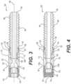
- FIG. 3is a sectional view of the assembly of FIG. 2 in a suture release position
- FIG. 4is a sectional view of the assembly of FIG. 2 in a suture restraining position
- FIG. 5is a perspective view of a fixation assembly according to an alternative exemplary embodiment
- FIG. 6is a sectional view of the assembly of FIG. 5 in a suture release position
- FIG. 7is a sectional view of the assembly of FIG. 5 in a suture restraining position
- FIG. 8is a side elevational view of a fixation assembly according to an alternative exemplary embodiment
- FIG. 9is a sectional view of the assembly of FIG. 8 in a suture release position
- FIG. 10is a sectional view of the assembly of FIG. 8 in a suture restraining position
- FIG. 11is a side elevational view of a fixation assembly according to an alternative exemplary embodiment
- FIG. 12is a side elevational view of the assembly of FIG. 11 with anchor legs in a deployed position
- FIG. 13is a sectional view of the assembly of FIG. 11 with the anchor legs in the deployed position;
- FIG. 14is a perspective view of the anchor used with the assembly of FIG. 11 ;
- FIG. 15is a side elevational view of a fixation assembly according to an alternative exemplary embodiment
- FIG. 16is a side elevational view of the assembly of FIG. 15 with anchor legs in a deployed position
- FIG. 17is a sectional view of the assembly of FIG. 15 with the anchor legs in the deployed position;
- FIG. 18is a perspective view of the assembly of FIG. 15 with the anchors deployed;
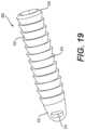
- FIG. 19is a perspective view of a fixation device according to an alternative exemplary embodiment
- FIG. 20is a perspective view of a fixation device according to another alternative exemplary embodiment
- FIG. 21is a sectional view of the device of FIG. 20 ;
- FIG. 22is a perspective view of a pair of fixation assemblies according to an alternative exemplary embodiment embedded in a tibia and used to reduce a syndesmosis;
- FIG. 23is a perspective view of a washer with a buckle used with the assembly of
- FIG. 22
- FIG. 24is a sectional view of the assembly of FIG. 22 ;
- FIG. 25is a perspective view of a fixation device according to an alternative embodiment
- FIG. 26is a side elevational view, in section, of a washer with a cam operated buckle in a release position according to an alternative exemplary embodiment
- FIG. 27is a side elevational view, in section, of the washer with am operated buckle of FIG. 26 in a locking position
- FIG. 28is a sectional view showing an exemplary method of reducing a syndesmosis according to an alternative exemplary embodiment
- FIG. 29is a sectional view of the embodiment of FIG. 28 with a clamp connecting two sutures;
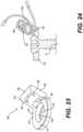
- FIG. 30is a perspective view of an exemplary clamping tool used to clamp the clamp of FIG. 29 ;
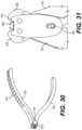
- FIG. 31is a top plan view of a staple inserted into the clamp of FIG. 30 ;
- FIG. 32is a top plan view of the clamp and staple of FIG. 31 having clamped down on the staple.
- FIG. 33is a schematic view of a fixation assembly according to an alternative exemplary embodiment.
- proximalis intended to mean a direction closer to a clinician implanting the inventive devices and the term “distal” is intended to mean a direction farther from the clinician.
- exemplaryis used herein to mean serving as an example, instance, or illustration. Any aspect or design described herein as “exemplary” is not necessarily to be construed as preferred or advantageous over other aspects or designs. Rather, use of the word exemplary is intended to present concepts in a concrete fashion.
- the term “or”is intended to mean an inclusive “or” rather than an exclusive “or”. That is, unless specified otherwise, or clear from context, “X employs A or B” is intended to mean any of the natural inclusive permutations. That is, if X employs A; X employs B; or X employs both A and B, then “X employs A or B” is satisfied under any of the foregoing instances.
- the articles “a” and “an” as used in this application and the appended claimsshould generally be construed to mean “one or more” unless specified otherwise or clear from context to be directed to a singular form.
- each numerical value and rangeshould be interpreted as being approximate as if the word “about” or “approximately” preceded the value of the value or range.
- figure numbers and/or figure reference labels in the claimsis intended to identify one or more possible embodiments of the claimed subject matter in order to facilitate the interpretation of the claims. Such use is not to be construed as necessarily limiting the scope of those claims to the embodiments shown in the corresponding figures.
- Couplerefers to any manner known in the art or later developed of joining or connecting two or more elements directly or indirectly to one another, and the interposition of one or more additional elements is contemplated, although not required. Conversely, the terms “directly coupled,” “directly connected,” etc., imply the absence of such additional elements.
- fixation device assembliesthat can be used in syndesmosis fixation.
- the devices and assemblies described hereincan be attached to a tibia 40 in two locations, with a suture 50 or suture tape connected to each device and wrapped around a fibula 42 to stabilize the syndesmosis.
- a simplified illustration of fixation device assemblies described hereinis shown in FIG. 1 , using generic screws 30 implanted into a tibia 40 on either side of a fibula 42 , with a suture 50 or suture tape 52 connected to screws 30 and wrapped over fibula 42 to draw fibula 42 closer to tibia 40 and reduce the syndesmosis.
- a syndesmosis fixation assembly 100(“assembly 100 ”) according to a first exemplary embodiment is shown.
- Assembly 100includes a suture retaining portion 110 , a suture securing portion 140 , and a bone insertion portion 180 .
- Assembly 100is cannulated along a central longitudinal axis 102 to allow for the optional use of a guide wire through assembly 100 to assist in inserting assembly 100 into bone.
- Suture retaining portion 110includes a generally hollow body 112 having a proximal portion 114 , a distal portion 116 , and an intermediate portion 118 , between the proximal portion 114 and the distal portion 116 .
- Proximal portion 114includes a cavity 119 having internal threads 120 that are sized to mate with external threads 142 on suture securing portion 140 .
- Distal portion 116includes a plurality of distally extending fingers 122 that are separated from adjacent fingers 122 by a longitudinal gap 124 . Fingers 122 form an internal space 125 in distal portion 116 . In an exemplary embodiment, four fingers 122 are provided, although those skilled in the art will recognize that more or less than four fingers 122 can be provided. A distal end of each finger 122 includes an internal lip 126 that is used to engage bone insertion portion 180 . Internal space 125 has an internally extending radial lip 128 that narrows internal space 125 in a proximal direction.
- Intermediate portion 118includes a plurality of suture openings 130 formed therein.
- suture openings 130include a first suture opening 130 a and a second suture opening 130 b that are diametrically opposed from each other.
- Suture securing portion 140comprises a set screw that is insertable into cavity 119 and is movable between a first position, shown in FIG. 2 , wherein a suture 50 is moveable within the suture retaining portion and a second position, shown in FIG. 3 , wherein the suture 50 is frictionally secured within suture retaining portion 110 .
- Bone insertion portion 180includes a distal bone insertion end 182 that is adapted for insertion into a bone.
- Distal bone insertion end 182includes a threaded portion 184 for gripping the bone.
- Bone insertion portion 180also includes a proximal bone insertion end 186 connected to suture retaining portion 110 .
- Proximal bone insertion end 186includes a radially extending lip 188 that is used to retain suture retaining portion 110 .
- a hex head 190is located proximally of lip 188 and is used to insert bone insertion portion 180 into a bone.
- bone insertion portion 180is threaded sub-flush into bone, either using a guide wire (not shown) or, alternatively, without a guide wire.
- a suture 50is inserted into first suture opening 130 a through suture retaining portion 110 and out second suture opening 130 b.
- Suture retaining portion 110is secured onto proximal bone insertion end 186 such that lip 126 on suture retaining portion 110 is forced over lip 188 on bone insertion portion 180 to rotatably secure suture retaining portion 110 onto bone insertion portion 180 .
- Suture 50can be tensioned by pulling on a free end 58 .
- Suture securing portion 140can be screwed down into cavity 119 to frictionally secure suture 50 within suture retaining portion 110 .
- a syndesmosis fixation assembly 200(“assembly 200 ”) according to an alternative exemplary embodiment is shown.
- Assembly 200includes a suture retaining portion 210 , a suture securing portion 240 , and a bone insertion portion 280 .
- Suture retaining portion 210includes a generally hollow body 212 having a proximal portion 214 and a distal portion 216 .
- Proximal portion 214includes a cavity 219 having internal threads 220 that are sized to mate with external threads 242 on suture securing portion 240 .
- Proximal portion 214also includes a plurality of suture openings 218 extending therethrough.
- Proximal portion 214also includes a cap 215 .
- Distal portion 216includes a head 222 having a circular outer perimeter 223 and a threaded body 224 having a narrower cross section than head 222 .
- Head 222has a cavity 225 adapted to receive an insertion tool 206 to rotate head 222 .
- cavity 225accepts a hex head driver.
- Head 222is sized to fit within cap 215 so that head 222 rotatably engages cap 215 .
- Threaded body 224is sized to internally thread into a proximal threaded cavity 285 in a proximal bone insertion end 283 of bone insertion portion 280 .
- Suture securing portion 240comprises a set screw 242 that is insertable into cavity 219 and is movable between a first position, shown in FIG. 6 , wherein a suture is moveable within suture retaining portion 210 and a second position, shown in FIG. 7 , wherein the suture can be frictionally secured within suture retaining portion 110 .
- Set screw 242is generally hollow with an internal hex face 244 and a distal end 248 .
- Bone insertion portion 280includes a distal bone insertion end 282 that is adapted for insertion into a bone.
- Distal bone insertion end 282includes a threaded portion 284 for gripping the bone.
- a central longitudinal axis 292extends between distal bone insertion end 282 and proximal bone insertion end 283 .
- Suture securing portion 240is threadingly disposed in cavity 219 and movable between a first position wherein the suture is moveable within suture retaining portion 210 and a second position wherein the suture is frictionally secured within suture retaining portion 210 .
- the first positionis a distal position relative to bone insertion portion 280 and the second position is a proximal position relative to the bone insertion portion 280 .
- head 222is inserted through cap 215 such that threaded body 224 extends distally from cap 215 .
- a suture(not shown) in inserted into one suture opening 218 and out another suture opening 218 .
- a retaining tool 202is inserted over suture retaining portion so that nubs 204 on distal ends of retaining tool 202 are inserted into diametrically opposing suture openings 218 and help to prevent rotation of cap 215 and the suture as assembly 200 is driven into the bone.
- threaded body 215is inserted into threaded cavity 285 in proximal bone insertion end 283 of bone insertion portion 280 and bone insertion portion 280 is driven into a bone using a driver 206 inserted into head 222 .
- an outer driver 208is used to rotate set screw 242 distally from the position shown in FIG. 6 to the position shown in FIG. 7 until distal end 248 of set screw 242 engages the top of head 222 , thereby securing the suture between set screw 242 and head 222 .
- a syndesmosis fixation assembly 300(“assembly 300 ”) according to an alternative exemplary embodiment is shown.
- Assembly 300includes a suture retaining portion 310 , a suture securing portion 340 , and a bone insertion portion 380 .
- Suture retaining portion 310includes a generally hollow body 312 having a proximal portion 314 and a distal portion 316 .
- Proximal portion 314includes internal threads 317 that accepts an insertion tool 302 .
- Proximal portion 314also includes a plurality of suture openings 318 extending therethrough. The plurality of suture openings 318 comprises a first opening 318 a and a second opening 318 b , proximal of first opening 318 a.
- Distal portion 316includes a cap 322 that is sized to receive suture securing portion 340 to frictionally engage a suture 50 that extends from suture openings 318 a , 318 b .
- a lip 324extends radially inwardly from cap 322 .
- Suture securing portion 340comprises a head 342 adapted to receive an insertion tool 304 to rotate head 342 .
- head 342accepts a hex head driver.
- Head 342ends in an annular shoulder 344 that engages insertion tool 304 .
- Head 342includes a bulbous body 348 extending distal of shoulder 344 , with a circumferential groove 350 formed therein.
- a passage 351is provided between body 348 and suture retaining portion 310 from first suture slot 318 a to second suture slot 318 b so that suture 50 can be slid along passage 351 .
- a distal end 352 of suture securing portion 340includes a threaded body 360 that is sized to internally thread into a proximal threaded cavity 385 in a proximal bone insertion end 383 of bone insertion portion 380 .
- a lip 388extends around distal end 352 between threaded body 360 and head 342 .
- Bone insertion portion 380includes a distal bone insertion end 382 that is adapted for insertion into a bone.
- Distal bone insertion end 382includes a threaded portion 384 for gripping the bone.
- a central longitudinal axis 392extends between distal bone insertion end 382 and proximal bone insertion end 383 .
- Suture securing portion 340is disposed in suture retaining portion 310 such that and movable between a first position wherein suture 50 is moveable within suture retaining portion 310 and a second position wherein suture 50 is frictionally secured suture retaining portion 310 and suture securing portion 340 .
- the first positionis a distal position relative to bone insertion portion 380 and the second position is a proximal position relative to the bone insertion portion 380 .
- threaded body 360 of suture securing portion 340is inserted through cap 322 such that threaded body 360 extends distally from cap 322 so that lip 324 is distal of lip 388 .
- a suture 50in inserted into one suture opening 218 a and out another suture opening 218 b.
- a first retaining tool 302is threaded onto internal threads 317 of proximal portion 314 to prevent rotation of suture retaining portion 310 .
- a second retaining tool 304is inserted into first retaining tool 302 and over head 342 until second training tool engages shoulder 344 .
- threaded body 360is inserted into threaded cavity 385 in proximal bone insertion end 383 of bone insertion portion 380 and bone insertion portion 380 is driven into a bone using a driver 304 inserted over head 342 until bone insertion portion is sub-flush with bone. Both drivers 302 , 304 can then be removed.
- cap 322is pulled proximally in the direction of arrow “A” in FIG. 9 so that lip 324 snaps over lip 388 and remains proximally over lip 388 .
- Suture retaining portion 310engages head 342 so that passage 351 is reduced, thereby frictionally securing suture 50 between body 348 of head 342 and suture retaining portion 310 .
- Assembly 400includes a suture retaining portion 410 , a suture securing portion 420 , and a bone insertion portion 440 .
- Suture retaining portion 410includes a plurality of distally extending fingers 412 that are separated from adjacent fingers 412 by a longitudinal gap 414 . Fingers 412 form an internal space 415 in suture retaining portion 410 . In an exemplary embodiment, four fingers 412 are provided, although those skilled in the art will recognize that more or less than four fingers 412 can be provided.
- Internal space 415has an internal thread 416 to threadingly accept and engage suture securing portion 420 .
- Internal space 415bottoms out on a landing 417 .
- Suture retaining portion 410also includes external ribbing 418 that allows assembly 400 to be inserted into a pre-drilled hole (not shown) but resists being pulled out.
- Suture securing portion 420includes a deformable spring anchor 422 that serves as both suture securing portion 420 as well as an anchor to secure assembly 400 in bone.
- Spring anchor 422includes a body portion 424 with a plurality of anchor legs 426 extending outwardly therefrom. The number of anchor legs 426 is the same number as the number of longitudinal gaps 414 such that each anchor leg 424 extends into a respective gap 414 , while body portion 424 can slide within internal space 415 .
- Suture securing portion 420further includes a set screw 428 that is insertable into internal space 415 .
- Set screw 428has a blunt distal tip 430 and a proximal head 432 that is configured to accept a driver (not shown) for rotating set screw 428 distally into internal space 415 .
- Set screw 428has an external thread 434 that mates with internal thread 416 to advance set screw 428 distally.
- Bone insertion portion 440extends distally from suture retaining portion 410 and includes a blunt distal tip 442 and external ribbing 444 that is an extension of the external ribbing 418 on suture retaining portion 410 .
- anchor legs 426are stored within the perimeter of fingers 412 , as shown in FIG. 11 .
- a suture(not shown) can be inserted into suture retaining portion 410 such that each end of the suture extends outwardly of one of gaps 414 .
- Bone securing portion 440is inserted into the bone and set screw 428 is advanced distally into internal space 415 , driving anchor 422 distally until anchor 422 frictionally engages the suture between anchor body portion 424 and landing 417 of internal space 415 .
- anchor legs 426are deformed to splay outwardly from the stored position, as shown in FIG. 11 , to a deployed position, as shown in FIGS. 12 and 13 .
- Assembly 450includes a suture retaining portion 460 , a suture securing portion 470 , and a bone insertion portion 490 .
- Suture retaining portion 460includes a plurality of distally extending generally semi-circular leg portions 462 that are separated from each other by a pair of diametrically opposed longitudinal gaps 464 . Leg portions 462 form an internal space 465 in suture retaining portion 460 .
- two diametrically opposed leg portions 462are provided, although those skilled in the art will recognize that more or less than two leg portions 462 can be provided.
- Internal space 465has an internal thread 466 to threadingly accept and engage suture securing portion 470 .
- Internal space 465bottoms out on a landing 467 .
- a pair of diametrically opposed suture slots 468extend from internal space 465 through each leg portion 462 .
- Suture slots 468are generally rectangular in cross section and are sized to allow a suture (not shown) to extend therethrough.
- Suture retaining portion 460also includes external ribbing 469 that allows assembly 450 to be inserted into a pre-drilled hole (not shown) but resists being pulled out.
- Suture securing portion 470includes a pair of diametrically opposed cam-operated blades 476 that form an anchor to secure assembly 450 in bone. Blades 476 are movable between a stored position in which blades 476 are stored wholly within gaps 464 , as shown in FIG. 15 , and a deployed position in which blades 476 extend outwardly of leg portions 462 , as shown in FIGS. 16 - 18 .
- Each blade 476includes a sloped cam face 478 that, in a stored position, extends obliquely relative to a longitudinal axis 480 of suture retaining portion 460 .
- a distal end 482 of each blade 476is pivotally attached to bone insertion portion 490 at a pivot 484 , located distal of landing 467 .
- Suture securing portion 470includes a set screw 479 that is insertable into internal space 465 .
- Set screw 479has a blunt distal tip 480 and a proximal head 482 that is configured to accept a driver (not shown) for rotating set screw 479 distally into internal space 465 .
- Set screw 479has an external thread 484 that mate with internal thread 466 to advance set screw 479 distally.
- Bone insertion portion 490extends distally from suture retaining portion 460 and includes a blunt distal tip 492 and external ribbing 494 that is an extension of the external ribbing 468 on suture retaining portion 460 .
- blades 476are stored within the perimeter of leg portions 462 .
- a suture(not shown) can be inserted into suture retaining portion 460 such that each end of the suture extends outwardly of one of suture slots 468 .
- Bone insertion portion 490is inserted into the bone and set screw 479 is advanced distally into internal space 465 , engaging cam face 478 of each blade 476 and pushing blades 476 outwardly through their respective gap 464 to secure assembly 450 into bone.
- set screw 479engages the suture and frictionally secures the suture between distal tip 480 and landing 467 .
- an anchor 830includes a distal tip 832 with a transverse passage 834 passing through.
- Anchor 830also has a proximal end 836 configured to accept a driver (not shown).
- a body 838 having uni-directional ribbing 840extends from proximal end 836 to distal tip 832 .
- suture 50 or suture tape 52(not shown) is passed through transverse passage 834 and anchor is tapped into a pre-drilled hole on tibia 40 (not shown). Suture 50 or suture tape 52 is wedged between anchor 830 and the wall of hole.
- an anchor 880includes a cannulated body 882 having an external thread 884 .
- a distal tip 886includes a transverse, first passage 888 and an oblique, second passage 890 proximal of first passage 888 .
- Second passage 890includes a first portion 891 that extends obliquely upwardly into an internal cannula 892 and a second portion 894 , diametrically opposite from first portion 891 , that also extends obliquely upwardly into internal cannula 892 .
- Internal cannula 892extends from first passage 888 to a proximal end 896 that can include a hex head 898 to accommodate a driver (not shown). The driver can be cannulated to allow a suture to extend therethrough.
- Suture 50 or suture tape 52is looped through either first passage 888 or second passage 890 and passes through cannula 892 to proximal end 896 .
- Assembly 900includes a washer 910 and a buckle 920 extending outwardly from washer 910 .
- a suture tape 52is secured to buckle 920 .
- Washer 910includes a generally annular body 912 having a flat top surface 914 and a tapered inner diameter 916 .
- a circular opening 918is formed within inner diameter 916 and is sized to allow a fixation screw to be inserted therethrough.
- Buckle 920extends at an upward oblique angle from top surface 914 and includes parallel side walls 922 , 924 , a top connecting member 926 , and a central connecting member 928 that each span and connect sides 922 , 924 to each other.
- a first, lower gap 930is formed between central connecting member 928 and body 912
- a second, upper gap 934is formed between central connecting member 928 and top member 926 .
- two screws 70 with washers 910are inserted into tibia 40 so that suture tape 52 can be wrapped around fibula 42 .
- a first end 54 of suture tape 52is secured to a first buckle 920 .
- a second end 56 of suture tape 52stretched over fibula 42 and is inserted through lower gap 930 distal from washer 910 toward washer 910 .
- Second end 56is then extended upwardly and over top connecting member 926 and then inserted through upper gap 934 distal from washer 910 toward washer 910 .
- Second end 56is then inserted through lower gap 932 , proximate to washer 910 away from washer 910 .
- Second end 56is then pulled upwardly, tightening suture tape 52 against fibula 42 .
- second end 56can be inserted through gaps 932 , 934 prior to securing washer 910 to tibia 40 , then securing washer 910 to tibia 40 , and then tightening suture tape 52 around fibula.
- Screw 1000has a distal tip 1002 and a proximal end 1004 .
- a threaded body 1010can extend between tip 1002 and proximal end 1004 .
- Body 1010can have varying outer diameters along the length of body, such as a narrow body portion 1012 toward distal tip 1002 and a wider body portion 1014 toward proximal end 1004 .
- Proximal end 1004includes a buckle 1030 similar to buckle 920 described above with respect to assembly 900 .
- This washerless embodimentallows buckle 1030 to be driven sub-flush of the bone cortex.
- the tensioning method for suture tape 52is the same as for assembly 900 described above.
- Assembly 1100includes a washer 1110 with a buckle 1120 that incorporates a cam 1130 .
- Washer 1110includes a generally annular body 1112 having a flat top surface 1114 and a tapered inner diameter 1116 .
- a circular opening 1118is formed within inner diameter 1116 and is sized to allow a fixation screw to be inserted therethrough.
- Buckle 1120extends at an upward oblique angle from top surface 1114 and includes parallel side walls 1122 , 1124 and a top connecting member 1126 that spans and connects sides 1122 , 1124 to each other. Side walls 1122 , 1124 each include a transverse slot 1128 . Connecting member 1126 includes a concave inner face 1129 .
- cam 1130Each side of cam 1130 includes a pivot portion 1132 that is inserted into transverse slot 1128 to that cam 1130 can pivot about transverse slot 1128 .
- Cam 1130also includes a lobe 1134 positioned over that is used to bias suture tape 52 against top surface 1112 of washer 1110 and a slot 1136 through which suture tape 52 is inserted.
- First end 54 of suture tape 52can be fixed to another securing device, not shown.
- Second end 56 of suture tape 52can be inserted into gap 1127 distal from washer 110 toward washer 1110 and under lobe 1134 .
- Second end 56is then inserted through slot 1136 in cam 1130 .
- cam 1130is pivoted along concave inner face 1129 from the position shown in FIG. 26 to the position shown in FIG. 27 .
- Lobe 1134is rotated to pinch suture tape 52 down on top surface 114 , securing suture tape 52 to assembly 1110 .
- buckle 1120 with cam 1130can be used on other securing devices, such as, for example, on screw 1000 .
- Assembly 1200includes screws 70 that are implanted into tibia 40 on either side of fibula 42 .
- a suture 50is attached to each screw 70 so that each suture 50 has a free end 58 .
- Free ends 58are drawn over fibula 42 and clamped together, such as by staple 1202 .
- Staple 1202can be clamped around free ends 58 by a clamping instrument 1210 .
- Clamping instrument 1210includes a pair of arms 1212 , 1214 that are pivotally attached to each other at a pivot 1216 .
- Instrument 1210includes a staple receiver 1215 on an opposing side of pivot 1216 .
- Clamping teeth 1218 , 1220are attached to distal ends of arms 1212 , 1214 , respectively on the opposing side of pivot 1216 and on either side of receiver 1215 .
- staple 1202is inserted into receiver 1215 .
- Free ends 58 of sutures 50are inserted into staple 1202 and arms 1214 , 1216 are compressed toward each other as shown in FIG. 32 so that clamping teeth 1218 , 1220 close down on staple arms 1204 to clamp free ends 58 of suture 50 within staple.
- Assembly 1300includes a band 1302 that connects two separate sutures 50 to each other. Sutures 50 can be secured to a bone (not shown) via any of the anchors disclosed herein, such that free ends 58 of sutures extend away from the anchors. Band 1302 includes clamps 1304 are either end thereof to secure free ends 58 of sutures 50 .
- Each clamp 1304includes a body 1306 having a closure 1308 pivotally attached thereto. Free end 58 of suture 50 can be inserted through clamp 1304 between body 1306 and closure 1308 . Closure 1308 can be pivoted to body 1306 to secure suture 50 between body 1306 and closure 1308 .
- band 1302can be slid along either suture 50 to a select location prior to securing suture 50 to band 1302 in order to avoid engaging any anatomically challenging areas.
- the anchors and assemblies disclosed hereincan be constructed from biocompatible materials, such as stainless steel, titanium, or other suitable materials or combinations thereof.
Landscapes
- Health & Medical Sciences (AREA)
- Life Sciences & Earth Sciences (AREA)
- Surgery (AREA)
- Animal Behavior & Ethology (AREA)
- General Health & Medical Sciences (AREA)
- Engineering & Computer Science (AREA)
- Biomedical Technology (AREA)
- Heart & Thoracic Surgery (AREA)
- Veterinary Medicine (AREA)
- Public Health (AREA)
- Orthopedic Medicine & Surgery (AREA)
- Medical Informatics (AREA)
- Rheumatology (AREA)
- Molecular Biology (AREA)
- Nuclear Medicine, Radiotherapy & Molecular Imaging (AREA)
- Cardiology (AREA)
- Oral & Maxillofacial Surgery (AREA)
- Transplantation (AREA)
- Vascular Medicine (AREA)
- Surgical Instruments (AREA)
Abstract
Description
The present device relates to constructs that are used in the fixation of syndesmosis disruptions.
A present method for syndesmotic ankle fixation requires screws or suture button systems. Both types of these fixation devices are inserted through the fibula and into the syndesmosis. The cross section of the fibula is relatively small, particularly at the syndesmosis, which can result in the clinician having a difficult time inserting the screw or suture button system through the fibula.
Accordingly, there exists a need for a syndesmosis fixation system that does not extend through the fibula.
This Summary is provided to introduce a selection of concepts in a simplified form that are further described below in the Detailed Description. This Summary is not intended to identify key features or essential features of the claimed subject matter, nor is it intended to be used to limit the scope of the claimed subject matter.
According to one embodiment, a syndesmosis fixation assembly may include a plurality of implantable devices configured to aid in anatomic reduction.
In one embodiment, the syndesmosis fixation assembly may include a suture retaining portion having a plurality of suture openings formed therein and a suture securing portion rotatably connected to the suture retaining portion. The suture securing portion is movable between a first position wherein a suture is moveable within the suture retaining portion and a second position wherein the suture is frictionally secured within the suture retaining portion. A bone insertion portion has a distal bone insertion end adapted for insertion into a bone, a proximal bone insertion end connected to the suture retaining portion, and a central longitudinal axis extending between the distal bone insertion end and the proximal bone insertion end.
In an alternative embodiment, the syndesmosis fixation assembly includes a suture retaining portion having a plurality of suture openings formed therein and a suture extending through each of the plurality of suture openings. A suture securing portion is connected to the suture retaining portion. The suture securing portion is movable between a first position wherein the suture is moveable within the suture retaining portion and a second position wherein the suture is frictionally secured within the suture retaining portion. A bone insertion portion has a distal bone insertion end adapted for insertion into a bone and a proximal bone insertion end connected to the suture retaining portion.
In still another alternative embodiment, the syndesmosis fixation assembly comprises a suture retaining portion and a suture securing portion adapted to move from a first position wherein a suture in the suture retaining portion is moveable with respect to the suture retaining portion and a second position wherein the suture is fixed with respect to the suture retaining portion. A bone insertion portion has a distal portion adapted for insertion into a bone and a proximal portion connected to the suture retaining portion.
Other aspects, features, and advantages of the present device will become more fully apparent from the following detailed description, the appended claims, and the accompanying drawings in which like reference numerals identify similar or identical elements.
In the drawings, like numerals indicate like elements throughout. Certain terminology is used herein for convenience only and is not to be taken as a limitation on the present device. The terminology includes the words specifically mentioned, derivatives thereof and words of similar import. As used herein, the term “proximal” is intended to mean a direction closer to a clinician implanting the inventive devices and the term “distal” is intended to mean a direction farther from the clinician.
The embodiments illustrated below are not intended to be exhaustive or to limit the device to the precise form disclosed. These embodiments are chosen and described to best explain the principle of the device and its application and practical use and to enable others skilled in the art to best utilize the device.
Reference herein to “one embodiment” or “an embodiment” means that a particular feature, structure, or characteristic described in connection with the embodiment can be included in at least one embodiment of the device. The appearances of the phrase “in one embodiment” in various places in the specification are not necessarily all referring to the same embodiment, nor are separate or alternative embodiments necessarily mutually exclusive of other embodiments. The same applies to the term “implementation.”
As used in this application, the word “exemplary” is used herein to mean serving as an example, instance, or illustration. Any aspect or design described herein as “exemplary” is not necessarily to be construed as preferred or advantageous over other aspects or designs. Rather, use of the word exemplary is intended to present concepts in a concrete fashion.
Additionally, the term “or” is intended to mean an inclusive “or” rather than an exclusive “or”. That is, unless specified otherwise, or clear from context, “X employs A or B” is intended to mean any of the natural inclusive permutations. That is, if X employs A; X employs B; or X employs both A and B, then “X employs A or B” is satisfied under any of the foregoing instances. In addition, the articles “a” and “an” as used in this application and the appended claims should generally be construed to mean “one or more” unless specified otherwise or clear from context to be directed to a singular form.
Unless explicitly stated otherwise, each numerical value and range should be interpreted as being approximate as if the word “about” or “approximately” preceded the value of the value or range.
The use of figure numbers and/or figure reference labels in the claims is intended to identify one or more possible embodiments of the claimed subject matter in order to facilitate the interpretation of the claims. Such use is not to be construed as necessarily limiting the scope of those claims to the embodiments shown in the corresponding figures.
It should be understood that the steps of the exemplary methods set forth herein are not necessarily required to be performed in the order described, and the order of the steps of such methods should be understood to be merely exemplary. Likewise, additional steps may be included in such methods, and certain steps may be omitted or combined, in methods consistent with various embodiments of the present device.
Although the elements in the following method claims, if any, are recited in a particular sequence with corresponding labeling, unless the claim recitations otherwise imply a particular sequence for implementing some or all of those elements, those elements are not necessarily intended to be limited to being implemented in that particular sequence.
Also for purposes of this description, the terms “couple,” “coupling,” “coupled,” “connect,” “connecting,” or “connected” refer to any manner known in the art or later developed of joining or connecting two or more elements directly or indirectly to one another, and the interposition of one or more additional elements is contemplated, although not required. Conversely, the terms “directly coupled,” “directly connected,” etc., imply the absence of such additional elements.
The present disclosure provides embodiments of fixation device assemblies that can be used in syndesmosis fixation. The devices and assemblies described herein can be attached to atibia 40 in two locations, with asuture 50 or suture tape connected to each device and wrapped around afibula 42 to stabilize the syndesmosis. A simplified illustration of fixation device assemblies described herein is shown inFIG.1 , usinggeneric screws 30 implanted into atibia 40 on either side of afibula 42, with asuture 50 orsuture tape 52 connected toscrews 30 and wrapped overfibula 42 to drawfibula 42 closer totibia 40 and reduce the syndesmosis.
Referring toFIGS.2-4 , a syndesmosis fixation assembly100 (“assembly 100”) according to a first exemplary embodiment is shown.Assembly 100 includes asuture retaining portion 110, asuture securing portion 140, and abone insertion portion 180.Assembly 100 is cannulated along a central longitudinal axis102 to allow for the optional use of a guide wire throughassembly 100 to assist in insertingassembly 100 into bone.
Suture retainingportion 110 includes a generally hollow body112 having a proximal portion114, a distal portion116, and an intermediate portion118, between the proximal portion114 and the distal portion116. Proximal portion114 includes a cavity119 having internal threads120 that are sized to mate with external threads142 onsuture securing portion 140.
Distal portion116 includes a plurality of distally extendingfingers 122 that are separated fromadjacent fingers 122 by alongitudinal gap 124.Fingers 122 form an internal space125 in distal portion116. In an exemplary embodiment, fourfingers 122 are provided, although those skilled in the art will recognize that more or less than fourfingers 122 can be provided. A distal end of eachfinger 122 includes an internal lip126 that is used to engagebone insertion portion 180. Internal space125 has an internally extending radial lip128 that narrows internal space125 in a proximal direction.
Intermediate portion118 includes a plurality of suture openings130 formed therein. In an exemplary embodiment, suture openings130 include a first suture opening130aand a second suture opening130bthat are diametrically opposed from each other.
Suture securingportion 140 comprises a set screw that is insertable into cavity119 and is movable between a first position, shown inFIG.2 , wherein asuture 50 is moveable within the suture retaining portion and a second position, shown inFIG.3 , wherein thesuture 50 is frictionally secured withinsuture retaining portion 110.
To insertassembly 100,bone insertion portion 180 is threaded sub-flush into bone, either using a guide wire (not shown) or, alternatively, without a guide wire. Asuture 50 is inserted into first suture opening130athroughsuture retaining portion 110 and out second suture opening130b.
Suture retainingportion 110 is secured onto proximalbone insertion end 186 such that lip126 onsuture retaining portion 110 is forced overlip 188 onbone insertion portion 180 to rotatably securesuture retaining portion 110 ontobone insertion portion 180.Suture 50 can be tensioned by pulling on afree end 58.
Suture securingportion 140 can be screwed down into cavity119 to frictionallysecure suture 50 withinsuture retaining portion 110.
Referring toFIGS.5-7 , a syndesmosis fixation assembly200 (“assembly 200”) according to an alternative exemplary embodiment is shown.Assembly 200 includes asuture retaining portion 210, asuture securing portion 240, and abone insertion portion 280.
Suture retainingportion 210 includes a generallyhollow body 212 having aproximal portion 214 and adistal portion 216.Proximal portion 214 includes acavity 219 havinginternal threads 220 that are sized to mate withexternal threads 242 onsuture securing portion 240.Proximal portion 214 also includes a plurality ofsuture openings 218 extending therethrough.Proximal portion 214 also includes acap 215.
Suture securingportion 240 comprises aset screw 242 that is insertable intocavity 219 and is movable between a first position, shown inFIG.6 , wherein a suture is moveable withinsuture retaining portion 210 and a second position, shown inFIG.7 , wherein the suture can be frictionally secured withinsuture retaining portion 110. Setscrew 242 is generally hollow with aninternal hex face 244 and adistal end 248.
Suture securingportion 240 is threadingly disposed incavity 219 and movable between a first position wherein the suture is moveable withinsuture retaining portion 210 and a second position wherein the suture is frictionally secured withinsuture retaining portion 210. The first position is a distal position relative tobone insertion portion 280 and the second position is a proximal position relative to thebone insertion portion 280.
To insertassembly 200,head 222 is inserted throughcap 215 such that threadedbody 224 extends distally fromcap 215. A suture (not shown) in inserted into onesuture opening 218 and out anothersuture opening 218. A retainingtool 202 is inserted over suture retaining portion so thatnubs 204 on distal ends of retainingtool 202 are inserted into diametrically opposingsuture openings 218 and help to prevent rotation ofcap 215 and the suture asassembly 200 is driven into the bone.
Next, threadedbody 215 is inserted into threadedcavity 285 in proximalbone insertion end 283 ofbone insertion portion 280 andbone insertion portion 280 is driven into a bone using adriver 206 inserted intohead 222. Then, anouter driver 208 is used to rotate setscrew 242 distally from the position shown inFIG.6 to the position shown inFIG.7 untildistal end 248 of setscrew 242 engages the top ofhead 222, thereby securing the suture betweenset screw 242 andhead 222.
Referring toFIGS.8-10 , a syndesmosis fixation assembly300 (“assembly 300”) according to an alternative exemplary embodiment is shown.Assembly 300 includes asuture retaining portion 310, asuture securing portion 340, and abone insertion portion 380.
Suture retainingportion 310 includes a generallyhollow body 312 having aproximal portion 314 and adistal portion 316.Proximal portion 314 includes internal threads317 that accepts aninsertion tool 302.Proximal portion 314 also includes a plurality ofsuture openings 318 extending therethrough. The plurality ofsuture openings 318 comprises afirst opening 318aand asecond opening 318b, proximal offirst opening 318a.
Suture securingportion 340 comprises ahead 342 adapted to receive aninsertion tool 304 to rotatehead 342. In an exemplary embodiment,head 342 accepts a hex head driver.Head 342 ends in anannular shoulder 344 that engagesinsertion tool 304.Head 342 includes abulbous body 348 extending distal ofshoulder 344, with acircumferential groove 350 formed therein. Apassage 351 is provided betweenbody 348 andsuture retaining portion 310 fromfirst suture slot 318atosecond suture slot 318bso thatsuture 50 can be slid alongpassage 351.
Adistal end 352 ofsuture securing portion 340 includes a threadedbody 360 that is sized to internally thread into a proximal threadedcavity 385 in a proximalbone insertion end 383 ofbone insertion portion 380. Alip 388 extends arounddistal end 352 between threadedbody 360 andhead 342.
Suture securingportion 340 is disposed insuture retaining portion 310 such that and movable between a first position whereinsuture 50 is moveable withinsuture retaining portion 310 and a second position whereinsuture 50 is frictionally securedsuture retaining portion 310 andsuture securing portion 340. The first position is a distal position relative tobone insertion portion 380 and the second position is a proximal position relative to thebone insertion portion 380.
Referring toFIGS.9 and10 , to insertassembly 300, threadedbody 360 ofsuture securing portion 340 is inserted throughcap 322 such that threadedbody 360 extends distally fromcap 322 so thatlip 324 is distal oflip 388. Asuture 50 in inserted into one suture opening218aand out another suture opening218b.
Afirst retaining tool 302 is threaded onto internal threads317 ofproximal portion 314 to prevent rotation ofsuture retaining portion 310. Asecond retaining tool 304 is inserted intofirst retaining tool 302 and overhead 342 until second training tool engagesshoulder 344.
Next, threadedbody 360 is inserted into threadedcavity 385 in proximalbone insertion end 383 ofbone insertion portion 380 andbone insertion portion 380 is driven into a bone using adriver 304 inserted overhead 342 until bone insertion portion is sub-flush with bone. Bothdrivers
To frictionallysecure suture 50,cap 322 is pulled proximally in the direction of arrow “A” inFIG.9 so thatlip 324 snaps overlip 388 and remains proximally overlip 388. Suture retainingportion 310 engageshead 342 so thatpassage 351 is reduced, thereby frictionally securingsuture 50 betweenbody 348 ofhead 342 andsuture retaining portion 310.
Referring toFIGS.11-14 , a syndesmosis fixation assembly400 (“assembly 400”) according to an alternative exemplary embodiment is shown.Assembly 400 includes asuture retaining portion 410, asuture securing portion 420, and abone insertion portion 440.
Suture retainingportion 410 includes a plurality of distally extendingfingers 412 that are separated fromadjacent fingers 412 by alongitudinal gap 414.Fingers 412 form aninternal space 415 insuture retaining portion 410. In an exemplary embodiment, fourfingers 412 are provided, although those skilled in the art will recognize that more or less than fourfingers 412 can be provided.
Suture securingportion 420 includes adeformable spring anchor 422 that serves as both suture securingportion 420 as well as an anchor to secureassembly 400 in bone.Spring anchor 422 includes abody portion 424 with a plurality ofanchor legs 426 extending outwardly therefrom. The number ofanchor legs 426 is the same number as the number oflongitudinal gaps 414 such that eachanchor leg 424 extends into arespective gap 414, whilebody portion 424 can slide withininternal space 415.
Suture securingportion 420 further includes aset screw 428 that is insertable intointernal space 415. Setscrew 428 has a bluntdistal tip 430 and aproximal head 432 that is configured to accept a driver (not shown) for rotating setscrew 428 distally intointernal space 415. Setscrew 428 has anexternal thread 434 that mates withinternal thread 416 to advance setscrew 428 distally.
In an insertion condition, anchorlegs 426 are stored within the perimeter offingers 412, as shown inFIG.11 . A suture (not shown) can be inserted intosuture retaining portion 410 such that each end of the suture extends outwardly of one ofgaps 414.Bone securing portion 440 is inserted into the bone and setscrew 428 is advanced distally intointernal space 415, drivinganchor 422 distally untilanchor 422 frictionally engages the suture betweenanchor body portion 424 and landing417 ofinternal space 415.
Asset screw 428 is further advanced distally, anchorlegs 426 are deformed to splay outwardly from the stored position, as shown inFIG.11 , to a deployed position, as shown inFIGS.12 and13 .
Referring toFIGS.15-18 , a syndesmosis fixation assembly450 (“assembly 450”) according to an alternative exemplary embodiment is shown.Assembly 450 includes asuture retaining portion 460, asuture securing portion 470, and abone insertion portion 490.
Suture retainingportion 460 includes a plurality of distally extending generallysemi-circular leg portions 462 that are separated from each other by a pair of diametrically opposedlongitudinal gaps 464.Leg portions 462 form aninternal space 465 insuture retaining portion 460. In an exemplary embodiment, two diametricallyopposed leg portions 462 are provided, although those skilled in the art will recognize that more or less than twoleg portions 462 can be provided.
Suture securingportion 470 includes a pair of diametrically opposed cam-operatedblades 476 that form an anchor to secureassembly 450 in bone.Blades 476 are movable between a stored position in whichblades 476 are stored wholly withingaps 464, as shown inFIG.15 , and a deployed position in whichblades 476 extend outwardly ofleg portions 462, as shown inFIGS.16-18 .
Eachblade 476 includes a slopedcam face 478 that, in a stored position, extends obliquely relative to alongitudinal axis 480 ofsuture retaining portion 460. Adistal end 482 of eachblade 476 is pivotally attached tobone insertion portion 490 at apivot 484, located distal oflanding 467.
Suture securingportion 470 includes aset screw 479 that is insertable intointernal space 465. Setscrew 479 has a bluntdistal tip 480 and aproximal head 482 that is configured to accept a driver (not shown) for rotating setscrew 479 distally intointernal space 465. Setscrew 479 has anexternal thread 484 that mate withinternal thread 466 to advance setscrew 479 distally.
In an insertion condition,blades 476 are stored within the perimeter ofleg portions 462. A suture (not shown) can be inserted intosuture retaining portion 460 such that each end of the suture extends outwardly of one ofsuture slots 468.Bone insertion portion 490 is inserted into the bone and setscrew 479 is advanced distally intointernal space 465, engagingcam face 478 of eachblade 476 and pushingblades 476 outwardly through theirrespective gap 464 to secureassembly 450 into bone. Asset screw 479 is further advanced distally, setscrew 479 engages the suture and frictionally secures the suture betweendistal tip 480 andlanding 467.
Alternatively, as shown inFIG.19 , ananchor 830 includes adistal tip 832 with atransverse passage 834 passing through.Anchor 830 also has aproximal end 836 configured to accept a driver (not shown). Abody 838 havinguni-directional ribbing 840 extends fromproximal end 836 todistal tip 832.
To insertanchor 830,suture 50 or suture tape52 (not shown) is passed throughtransverse passage 834 and anchor is tapped into a pre-drilled hole on tibia40 (not shown).Suture 50 orsuture tape 52 is wedged betweenanchor 830 and the wall of hole.
In an alternative embodiment shown inFIGS.20 and21 , ananchor 880 includes a cannulatedbody 882 having anexternal thread 884. Adistal tip 886 includes a transverse,first passage 888 and an oblique,second passage 890 proximal offirst passage 888.Second passage 890 includes afirst portion 891 that extends obliquely upwardly into aninternal cannula 892 and asecond portion 894, diametrically opposite fromfirst portion 891, that also extends obliquely upwardly intointernal cannula 892.Internal cannula 892 extends fromfirst passage 888 to a proximal end896 that can include ahex head 898 to accommodate a driver (not shown). The driver can be cannulated to allow a suture to extend therethrough.
An alternative embodiment of anassembly 900 is shown inFIGS.22-24 .Assembly 900 includes awasher 910 and abuckle 920 extending outwardly fromwasher 910. Asuture tape 52 is secured to buckle920.
Referring toFIGS.22 and24 , to useassembly 900, twoscrews 70 withwashers 910 are inserted intotibia 40 so thatsuture tape 52 can be wrapped aroundfibula 42. Afirst end 54 ofsuture tape 52 is secured to afirst buckle 920. Asecond end 56 ofsuture tape 52 stretched overfibula 42 and is inserted throughlower gap 930 distal fromwasher 910 towardwasher 910.Second end 56 is then extended upwardly and over top connectingmember 926 and then inserted through upper gap934 distal fromwasher 910 towardwasher 910.Second end 56 is then inserted throughlower gap 932, proximate towasher 910 away fromwasher 910.Second end 56 is then pulled upwardly, tighteningsuture tape 52 againstfibula 42.
Alternatively,second end 56 can be inserted throughgaps 932,934 prior to securingwasher 910 totibia 40, then securingwasher 910 totibia 40, and then tighteningsuture tape 52 around fibula.
An alternative embodiment includes ascrew 1000 shown inFIG.25 .Screw 1000 has adistal tip 1002 and aproximal end 1004. A threadedbody 1010 can extend betweentip 1002 andproximal end 1004.Body 1010 can have varying outer diameters along the length of body, such as anarrow body portion 1012 towarddistal tip 1002 and awider body portion 1014 towardproximal end 1004.
An alternative embodiment of anassembly 1100 is shown inFIGS.26 and27 .Assembly 1100 includes awasher 1110 with abuckle 1120 that incorporates acam 1130.
Each side ofcam 1130 includes apivot portion 1132 that is inserted intotransverse slot 1128 to thatcam 1130 can pivot abouttransverse slot 1128.Cam 1130 also includes alobe 1134 positioned over that is used to biassuture tape 52 againsttop surface 1112 ofwasher 1110 and aslot 1136 through which suturetape 52 is inserted.
First end54 ofsuture tape 52 can be fixed to another securing device, not shown.Second end 56 ofsuture tape 52 can be inserted into gap1127 distal fromwasher 110 towardwasher 1110 and underlobe 1134.Second end 56 is then inserted throughslot 1136 incam 1130. To securesuture tape 52,cam 1130 is pivoted along concaveinner face 1129 from the position shown inFIG.26 to the position shown inFIG.27 .Lobe 1134 is rotated to pinchsuture tape 52 down on top surface114, securingsuture tape 52 toassembly 1110.
Whileassembly 1100 is shown usingwasher 1110, those skilled in the art will recognize thatbuckle 1120 withcam 1130 can be used on other securing devices, such as, for example, onscrew 1000.
An alternative embodiment of anassembly 1200 is shown inFIGS.28-32 .Assembly 1200 includesscrews 70 that are implanted intotibia 40 on either side offibula 42. Asuture 50 is attached to eachscrew 70 so that eachsuture 50 has afree end 58. Free ends58 are drawn overfibula 42 and clamped together, such as bystaple 1202. Staple1202 can be clamped around free ends58 by aclamping instrument 1210.
Clampinginstrument 1210 includes a pair ofarms pivot 1216.Instrument 1210 includes astaple receiver 1215 on an opposing side ofpivot 1216. Clampingteeth arms pivot 1216 and on either side ofreceiver 1215.
As shown inFIG.31 ,staple 1202 is inserted intoreceiver 1215. Free ends58 ofsutures 50 are inserted intostaple 1202 andarms FIG.32 so that clampingteeth suture 50 within staple.
An alternative embodiment of anassembly 1300 is shown inFIG.33 .Assembly 1300 includes aband 1302 that connects twoseparate sutures 50 to each other.Sutures 50 can be secured to a bone (not shown) via any of the anchors disclosed herein, such that free ends58 of sutures extend away from the anchors.Band 1302 includesclamps 1304 are either end thereof to secure free ends58 ofsutures 50.
Eachclamp 1304 includes abody 1306 having aclosure 1308 pivotally attached thereto.Free end 58 ofsuture 50 can be inserted throughclamp 1304 betweenbody 1306 andclosure 1308.Closure 1308 can be pivoted tobody 1306 to securesuture 50 betweenbody 1306 andclosure 1308.
An advantage to usingband 1302 is thatband 1302 can be slid along eithersuture 50 to a select location prior to securingsuture 50 toband 1302 in order to avoid engaging any anatomically challenging areas.
The anchors and assemblies disclosed herein can be constructed from biocompatible materials, such as stainless steel, titanium, or other suitable materials or combinations thereof.
It will be further understood that various changes in the details, materials, and arrangements of the parts which have been described and illustrated in order to explain the nature of this device may be made by those skilled in the art without departing from the scope of the device as expressed in the following claims.
Claims (7)
1. A syndesmosis fixation assembly comprising:
a suture retaining portion having a plurality of suture openings formed therein and a distal cavity;
a suture securing portion rotatably connected to the suture retaining portion, wherein the suture securing portion is movable between a first position wherein a suture is moveable within the suture retaining portion and a second position wherein the suture is frictionally secured within the suture retaining portion; and
a bone insertion portion having:
a distal bone insertion end adapted for insertion into a bone;
a proximal bone insertion end inserted into the distal cavity for connection with the suture retaining portion; and
a central longitudinal axis extending between the distal bone insertion end and the proximal bone insertion end.
2. The syndesmosis fixation assembly according toclaim 1 , wherein the plurality of suture openings comprises a first suture opening and a second suture opening, diametrically opposite the first suture opening.
3. The syndesmosis fixation assembly according toclaim 1 , wherein the plurality of suture openings comprises a first suture opening on one side of the longitudinal axis and a second suture opening on the one side of the longitudinal axis.
4. The syndesmosis fixation assembly according toclaim 1 , wherein the suture retaining portion comprises a proximal cavity and wherein the suture securing portion is disposed in the cavity.
5. The syndesmosis fixation assembly according toclaim 4 , wherein the suture securing portion comprises a set screw.
6. A syndesmosis fixation assembly comprising:
a suture retaining portion having a plurality of suture openings formed therein and a distal cavity;
a suture extending through each of the plurality of suture openings;
a suture securing portion connected to the suture retaining portion, wherein the suture securing portion is movable between a first position wherein the suture is moveable within the suture retaining portion and a second position wherein the suture is frictionally secured within the suture retaining portion; and
a bone insertion portion having:
a distal bone insertion end adapted for insertion into a bone; and
a proximal bone insertion end inserted into the distal cavity for connection with the suture retaining portion.
7. A syndesmosis fixation assembly comprising:
a suture retaining portion having a distal cavity;
a suture securing portion adapted to move from a first position wherein a suture in the suture retaining portion is moveable with respect to the suture retaining portion and a second position wherein the suture is fixed with respect to the suture retaining portion; and
a bone insertion portion having a distal portion adapted for insertion into a bone and a proximal portion inserted into the distal cavity for connection with the suture retaining portion.
Priority Applications (3)
| Application Number | Priority Date | Filing Date | Title |
|---|---|---|---|
| US16/717,589US11723647B2 (en) | 2019-12-17 | 2019-12-17 | Syndesmosis fixation assembly |
| US18/340,505US12114850B2 (en) | 2019-12-17 | 2023-06-23 | Syndesmosis fixation assembly |
| US18/884,183US20250000505A1 (en) | 2019-12-17 | 2024-09-13 | Syndesmosis fixation assembly |
Applications Claiming Priority (1)
| Application Number | Priority Date | Filing Date | Title |
|---|---|---|---|
| US16/717,589US11723647B2 (en) | 2019-12-17 | 2019-12-17 | Syndesmosis fixation assembly |
Related Child Applications (1)
| Application Number | Title | Priority Date | Filing Date |
|---|---|---|---|
| US18/340,505ContinuationUS12114850B2 (en) | 2019-12-17 | 2023-06-23 | Syndesmosis fixation assembly |
Publications (2)
| Publication Number | Publication Date |
|---|---|
| US20210177394A1 US20210177394A1 (en) | 2021-06-17 |
| US11723647B2true US11723647B2 (en) | 2023-08-15 |
Family
ID=76316409
Family Applications (3)
| Application Number | Title | Priority Date | Filing Date |
|---|---|---|---|
| US16/717,589Active2042-02-09US11723647B2 (en) | 2019-12-17 | 2019-12-17 | Syndesmosis fixation assembly |
| US18/340,505ActiveUS12114850B2 (en) | 2019-12-17 | 2023-06-23 | Syndesmosis fixation assembly |
| US18/884,183PendingUS20250000505A1 (en) | 2019-12-17 | 2024-09-13 | Syndesmosis fixation assembly |
Family Applications After (2)
| Application Number | Title | Priority Date | Filing Date |
|---|---|---|---|
| US18/340,505ActiveUS12114850B2 (en) | 2019-12-17 | 2023-06-23 | Syndesmosis fixation assembly |
| US18/884,183PendingUS20250000505A1 (en) | 2019-12-17 | 2024-09-13 | Syndesmosis fixation assembly |
Country Status (1)
| Country | Link |
|---|---|
| US (3) | US11723647B2 (en) |
Families Citing this family (5)
| Publication number | Priority date | Publication date | Assignee | Title |
|---|---|---|---|---|
| US10820918B2 (en) | 2015-07-17 | 2020-11-03 | Crossroads Extremity Systems, Llc | Transosseous guide and method |
| US12383253B2 (en) | 2015-08-04 | 2025-08-12 | Crossroads Extremity Systems, Llc | Suture anchor |
| US11723647B2 (en)* | 2019-12-17 | 2023-08-15 | Globus Medical, Inc. | Syndesmosis fixation assembly |
| WO2023278412A1 (en)* | 2021-06-30 | 2023-01-05 | Dodson Mark A | Anchoring apparatus |
| CN115005907A (en)* | 2022-05-25 | 2022-09-06 | 尤尼泰科(重庆)医疗科技有限公司 | A wire anchor |
Citations (288)
| Publication number | Priority date | Publication date | Assignee | Title |
|---|---|---|---|---|
| US254473A (en)* | 1882-03-07 | Rope-clamp | ||
| US1105105A (en) | 1912-02-10 | 1914-07-28 | William O'n Sherman | Surgical appliance. |
| US2486303A (en) | 1948-04-29 | 1949-10-25 | Harry Herschel Leiter | Surgical appliance for bone fractures |
| US2907978A (en)* | 1957-07-25 | 1959-10-06 | Thomas & Betts Corp | Electrical connector |
| US3463148A (en) | 1966-01-20 | 1969-08-26 | Richards Mfg Co | Bone plate |
| US3695259A (en) | 1970-11-10 | 1972-10-03 | Clyde E Yost | Bone plate |
| US3716050A (en) | 1971-02-11 | 1973-02-13 | F Johnston | Olecranon plate |
| US4219015A (en) | 1977-04-22 | 1980-08-26 | Institut Straumann Ag | Plates for osteosynthesis |
| US4493317A (en) | 1980-11-20 | 1985-01-15 | Synthes Ltd. (U.S.A.) | Surgical compression plate and drill guide |
| US4524765A (en) | 1981-12-09 | 1985-06-25 | Zbikowski Juan | Functional attachment system for osteosynthesis by means of compression plates |
| US4651724A (en) | 1984-05-18 | 1987-03-24 | Technomed Gmk | Bone joining plate |
| US4683878A (en) | 1985-04-29 | 1987-08-04 | Kirschner Medical Corporation | Osteosynthetic fixation plate |
| US4781183A (en) | 1986-08-27 | 1988-11-01 | American Cyanamid Company | Surgical prosthesis |
| US4867144A (en) | 1986-04-14 | 1989-09-19 | Huta Baildon | Plate for connecting base splinters with bone shafts |
| US4923471A (en) | 1989-10-17 | 1990-05-08 | Timesh, Inc. | Bone fracture reduction and fixation devices with identity tags |
| US4966599A (en) | 1987-04-07 | 1990-10-30 | Pollock Richard A | Anatomical precontoured plating, instruments and methods |
| US5002544A (en) | 1987-12-02 | 1991-03-26 | Synthes (U.S.A.) | Osteosynthetic pressure plate osteosynthetic compression plate |
| US5041114A (en) | 1986-06-23 | 1991-08-20 | Pfizer Hospital Products Group, Inc. | Modular femoral fixation system |
| US5151103A (en) | 1987-11-03 | 1992-09-29 | Synthes (U.S.A.) | Point contact bone compression plate |
| US5259398A (en) | 1989-10-26 | 1993-11-09 | Giuseppe Vrespa | Method for fixing prosthesis to bones |
| US5364399A (en) | 1993-02-05 | 1994-11-15 | Danek Medical, Inc. | Anterior cervical plating system |
| US5372598A (en) | 1987-05-14 | 1994-12-13 | Howmedica Gmbh | Small bone plate for cranial or facial fractures or the like |
| US5423826A (en) | 1993-02-05 | 1995-06-13 | Danek Medical, Inc. | Anterior cervical plate holder/drill guide and method of use |
| US5468242A (en) | 1993-11-19 | 1995-11-21 | Leibinger Gmbh | Form-fitting mesh implant |
| USD365634S (en) | 1993-09-23 | 1995-12-26 | Timesh, Inc. | Metallic surgical grid material |
| US5489305A (en) | 1994-10-03 | 1996-02-06 | Timesh, Inc. | Mandibular prostheses |
| US5527311A (en) | 1991-11-13 | 1996-06-18 | Howmedica Gmbh | Support for the human spine |
| US5578036A (en) | 1993-12-06 | 1996-11-26 | Stone; Kevin T. | Method and apparatus for fixation of bone during surgical procedures |
| US5601553A (en) | 1994-10-03 | 1997-02-11 | Synthes (U.S.A.) | Locking plate and bone screw |
| US5676667A (en) | 1995-12-08 | 1997-10-14 | Hausman; Michael | Bone fixation apparatus and method |
| US5690631A (en) | 1996-09-11 | 1997-11-25 | Walter Lorenz Surgical, Inc. | Multi-configurable plating system |
| US5709686A (en) | 1995-03-27 | 1998-01-20 | Synthes (U.S.A.) | Bone plate |
| US5709687A (en) | 1994-03-16 | 1998-01-20 | Pennig; Dietmar | Fixation pin for small-bone fragments |
| US5718704A (en) | 1995-02-14 | 1998-02-17 | Medoff; Robert J. | L-shape surgical buttress plate |
| US5718705A (en) | 1996-07-16 | 1998-02-17 | Sammarco; Giacomo J. | Internal fixation plate |
| US5746742A (en) | 1996-06-25 | 1998-05-05 | Bristol-Myers Squibb Company | Bone plate template |
| US5766176A (en) | 1996-09-11 | 1998-06-16 | Walter Lorenz Surgical, Inc. | Formable mesh |
| US5766175A (en) | 1994-11-22 | 1998-06-16 | Martinotti; Lucio | Retinaculum for orthopedic traumatology |
| US5779706A (en) | 1992-06-15 | 1998-07-14 | Medicon Eg | Surgical system |
| US5785712A (en) | 1996-04-16 | 1998-07-28 | Terray Corporation | Reconstruction bone plate |
| US5797914A (en) | 1995-12-21 | 1998-08-25 | Kls Martin, L.P. | Bone screw |
| US5814048A (en) | 1996-05-03 | 1998-09-29 | Sofamor Danek Properties, Inc. | Cranioplasty plates and method of installation |
| US5925048A (en) | 1998-03-13 | 1999-07-20 | Osteomed | Bone screw |
| US5938664A (en) | 1998-03-31 | 1999-08-17 | Zimmer, Inc. | Orthopaedic bone plate |
| US5957953A (en)* | 1996-02-16 | 1999-09-28 | Smith & Nephew, Inc. | Expandable suture anchor |
| US5961519A (en) | 1997-04-11 | 1999-10-05 | Kinamed, Inc. | Burr hole cover for cranial surgery |
| US5980540A (en) | 1997-04-11 | 1999-11-09 | Kinamed, Inc. | Perforated cover for covering spaces in the cranium and conforming to the shape of the cranium |
| US6001099A (en) | 1998-06-08 | 1999-12-14 | Huebner; Randall J. | Bone plate with varying rigidity |
| US6071291A (en) | 1997-10-21 | 2000-06-06 | Howmedica Leibinger Gmbh & Co. Kg (Leibinger) | Micro dynamic mesh |
| US6093201A (en) | 1999-01-19 | 2000-07-25 | Ethicon, Inc. | Biocompatible absorbable polymer plating system for tissue fixation |
| US6096040A (en) | 1996-06-14 | 2000-08-01 | Depuy Ace Medical Company | Upper extremity bone plates |
| US6107718A (en) | 1995-12-30 | 2000-08-22 | Robert Bosch Gmbh | Stator for an electrical machine |
| US6152927A (en) | 1997-05-15 | 2000-11-28 | Sdgi Holdings, Inc. | Anterior cervical plating system |
| US6206881B1 (en) | 1995-09-06 | 2001-03-27 | Synthes (Usa) | Bone plate |
| US6283969B1 (en) | 2000-03-10 | 2001-09-04 | Wright Medical Technology, Inc. | Bone plating system |
| US6309393B1 (en) | 1996-08-12 | 2001-10-30 | Synthes (U.S.A.) | Bone plate |
| US6322562B1 (en) | 1998-12-19 | 2001-11-27 | Dietmar Wolter | Fixation system for bones |
| US6364882B1 (en) | 2000-02-01 | 2002-04-02 | Hand Innovations, Inc. | Volar fixation system |
| US20020045901A1 (en) | 1999-03-09 | 2002-04-18 | Michael Wagner | Bone plate |
| USD458684S1 (en) | 2001-11-13 | 2002-06-11 | Zimmer, Inc. | Orthopaedic bone plate |
| USD458683S1 (en) | 2001-11-13 | 2002-06-11 | Zimmer, Inc. | Orthopaedic bone plate |
| US20020147463A1 (en)* | 2000-12-22 | 2002-10-10 | Jonathan Martinek | Suture screw |
| US6533786B1 (en) | 1999-10-13 | 2003-03-18 | Sdgi Holdings, Inc. | Anterior cervical plating system |
| JP2003210478A (en) | 2002-01-18 | 2003-07-29 | Ai-Medic:Kk | Plate for ulnar proximal crush fracture fixation |
| USD479331S1 (en) | 2002-11-05 | 2003-09-02 | Zimmer | Orthopedic bone plate |
| US6623486B1 (en) | 1999-09-13 | 2003-09-23 | Synthes (U.S.A.) | bone plating system |
| US6669701B2 (en) | 2000-01-27 | 2003-12-30 | Synthes (Usa) | Bone plate |
| US6712820B2 (en) | 2000-02-01 | 2004-03-30 | Hand Innovations, Inc. | Fixation plate system for dorsal wrist fracture fixation |
| US6730091B1 (en) | 1999-05-03 | 2004-05-04 | Medartis Ag | Blockable bone plate |
| FR2846870A1 (en) | 2002-11-07 | 2004-05-14 | Fixano | OSTEOSYNTHESIS MATERIAL FOR THE TREATMENT OF A "LONG" CUBITUS |
| US20040097937A1 (en) | 2002-11-19 | 2004-05-20 | Sandi Pike | Orthopedic bone plate |
| US6866665B2 (en) | 2003-03-27 | 2005-03-15 | Hand Innovations, Llc | Bone fracture fixation system with subchondral and articular surface support |
| US20050107796A1 (en) | 2003-09-29 | 2005-05-19 | Darin Gerlach | Bone plates and methods for provisional fixation using same |
| US20050131413A1 (en) | 2003-06-20 | 2005-06-16 | O'driscoll Shawn W. | Bone plate with interference fit screw |
| US20050187551A1 (en) | 2002-12-02 | 2005-08-25 | Orbay Jorge L. | Bone plate system with bone screws fixed by secondary compression |
| US6955677B2 (en) | 2002-10-15 | 2005-10-18 | The University Of North Carolina At Chapel Hill | Multi-angular fastening apparatus and method for surgical bone screw/plate systems |
| US6974461B1 (en) | 1999-09-14 | 2005-12-13 | Dietmar Wolter | Fixation system for bones |
| US7063701B2 (en) | 1999-05-05 | 2006-06-20 | Sdgi Holdings, Inc. | Screws of cortical bone having a trailing end configured to cooperatively engage an implant |
| US20060149265A1 (en) | 2004-09-07 | 2006-07-06 | Anthony James | Minimal thickness bone plate locking mechanism |
| US7090676B2 (en) | 2002-11-19 | 2006-08-15 | Acumed Llc | Adjustable bone plates |
| US20060241607A1 (en) | 2005-03-31 | 2006-10-26 | Mark Myerson | Metatarsal fixation plate |
| US7137987B2 (en) | 2004-07-02 | 2006-11-21 | Wright Medical Technology, Inc. | Distal radius bone plating system with locking and non-locking screws |
| US7153309B2 (en) | 2002-11-19 | 2006-12-26 | Acumed Llc | Guide system for bone-repair devices |
| US20070173840A1 (en) | 2006-01-11 | 2007-07-26 | Huebner Randall J | Bone plate with cover |
| US7250053B2 (en) | 2003-03-27 | 2007-07-31 | Depuy Products, Inc. | Low profile distal radius fracture fixation plate |
| US7294130B2 (en) | 2003-03-27 | 2007-11-13 | Depuy Products, Inc. | Distal radius fracture fixation plate having K-wire hole structured to fix a K-wire in one dimension relative to the plate |
| US20070270849A1 (en) | 2006-04-21 | 2007-11-22 | Orbay Jorge L | Fixation Plate With Multifunctional Holes |
| US20070288022A1 (en) | 2006-04-25 | 2007-12-13 | Stryker Trauma Gmbh | Bone reconstruction plate with improved fatigue resistance |
| US20080021477A1 (en) | 2006-03-07 | 2008-01-24 | Strnad Lee A | Orthopedic plate having threaded holes for locking screws or pegs and non-threaded holes for a variable axis locking mechanism |
| US7322983B2 (en) | 2002-02-12 | 2008-01-29 | Ebi, L.P. | Self-locking bone screw and implant |
| US7344538B2 (en) | 2005-03-31 | 2008-03-18 | Depuy Products, Inc. | Mid-foot fixation plate |
| US20080234749A1 (en) | 2007-01-26 | 2008-09-25 | Zimmer Technology, Inc. | Bone plate providing threaded locking head screw capture |
| US20080275510A1 (en) | 2007-05-03 | 2008-11-06 | Medartis Ag | Fixation Device, Combination of a Fixation Device with an Elongate Element, Arrangment with Such a Combination and Osteosynthesis Set |
| US20090024173A1 (en) | 2006-03-17 | 2009-01-22 | Reis Jr Geraldo Marins Dos | Bone Plate |
| US20090024172A1 (en) | 2007-07-18 | 2009-01-22 | Mario Angel Pizzicara | Blocked plate with combined holes, stability control and double angulation, to join fractured bones |
| US20090112270A1 (en)* | 2007-10-25 | 2009-04-30 | Smith & Nephew, Inc. | Anchor Assembly |
| US20090157124A1 (en)* | 2007-12-13 | 2009-06-18 | Smith & Nephew, Inc. | Anchoring System |
| US20090198285A1 (en) | 2008-02-06 | 2009-08-06 | Raven Iii Raymond | Subcondylar fracture fixation plate system for tubular bones of the hand |
| US20090228047A1 (en) | 2008-03-07 | 2009-09-10 | Guillaume Derouet | Device for reducing a fracture, in particular a distal radius fracture |
| US20090228010A1 (en) | 2008-03-10 | 2009-09-10 | Eduardo Gonzalez-Hernandez | Bone fixation system |
| US20090248084A1 (en) | 2008-03-27 | 2009-10-01 | Beat Hintermann | Systems and methods for performing ankle arthrodesis in a human patient |
| US7604657B2 (en) | 2005-09-19 | 2009-10-20 | Depuy Products, Inc. | Bone fixation plate with complex suture anchor locations |
| US20090281543A1 (en) | 2008-05-09 | 2009-11-12 | Skeletal Dynamics Llc | Formable bone plate, clamping apparatus, osteotomy system and method for reconstructing a bone |
| US20090299369A1 (en) | 2008-06-02 | 2009-12-03 | Skeletal Dynamics Llc | Hybrid Orthopedic Implant |
| US7632277B2 (en) | 2004-03-29 | 2009-12-15 | Woll Bioorthopedics Llc | Orthopedic intramedullary fixation system |
| US20090312760A1 (en) | 2004-10-07 | 2009-12-17 | Zimmer, Inc. | Bone fracture fixation system |
| US7635381B2 (en) | 2003-03-27 | 2009-12-22 | Depuy Products, Inc. | Anatomical distal radius fracture fixation plate with fixed-angle K-wire holes defining a three-dimensional surface |
| US7637928B2 (en) | 2004-01-26 | 2009-12-29 | Synthes Usa, Llc | Variable angle locked bone fixation system |
| US7655029B2 (en) | 2001-05-28 | 2010-02-02 | Synthes Usa, Llc | Bone plate |
| US7655047B2 (en) | 2003-04-16 | 2010-02-02 | Porex Surgical, Inc. | Craniofacial implant |
| US20100057086A1 (en) | 2008-08-29 | 2010-03-04 | Zimmer, Inc. | Anodized locking plate components |
| US7695472B2 (en) | 2003-03-26 | 2010-04-13 | Swiss Orthopedic Solutions Sa | Locking bone plate |
| US20100114097A1 (en) | 2007-04-27 | 2010-05-06 | Synthes Usa, Llc | Implant Devices Constructed with Metallic and Polymeric Components |
| US7717946B2 (en) | 2004-06-07 | 2010-05-18 | Degima Gmbh | Polymeric plate bendable without thermal energy and methods of manufacture |
| US7722653B2 (en) | 2003-03-26 | 2010-05-25 | Greatbatch Medical S.A. | Locking bone plate |
| US7771457B2 (en) | 2005-01-28 | 2010-08-10 | Orthohelix Surgical Designs, Inc. | Orthopedic plate for use in small bone repair |
| US7776076B2 (en) | 2004-05-11 | 2010-08-17 | Synthes Usa, Llc | Bone plate |
| USD622853S1 (en) | 2009-02-06 | 2010-08-31 | Osteomed L.P. | Hand bone fracture fixation plate |
| US20100318125A1 (en)* | 2009-04-15 | 2010-12-16 | Christian Gerber | Anchor Device For Knot-Free Attachment Of Tissue To A Bone |
| US7857838B2 (en) | 2003-03-27 | 2010-12-28 | Depuy Products, Inc. | Anatomical distal radius fracture fixation plate |
| US7867260B2 (en) | 2003-11-05 | 2011-01-11 | Koenigsee Implantate Und Instrumente Zur Osteosynthese Gmbh | Plate used to stabilise distal radius fractures |
| US7867261B2 (en) | 2006-03-17 | 2011-01-11 | Depuy Products, Inc. | Bone plate with variable torsional stiffness at fixed angle holes |
| US7875062B2 (en) | 2006-03-07 | 2011-01-25 | Warsaw Orthopedic, Inc. | Methods and devices for retaining bone plate anchors |
| US20110106086A1 (en) | 2008-04-03 | 2011-05-05 | Austofix Group Limited | Tool jig for bone implant assembly |
| US7951179B2 (en) | 2005-10-25 | 2011-05-31 | Anthem Orthopaedics Llc | Bone attachment screw |
| US7951178B2 (en) | 2006-04-03 | 2011-05-31 | Acumed Llc | Bone plates with hybrid apertures |
| USD643121S1 (en) | 2010-05-27 | 2011-08-09 | Ebi, Llc | Orthopedic wrist spanning bone plate |
| US20110218580A1 (en) | 2010-03-08 | 2011-09-08 | Stryker Trauma Sa | Bone fixation system with curved profile threads |
| CN201987653U (en) | 2010-12-22 | 2011-09-28 | 蔡林 | Clavicular hook steel plate |
| USD646785S1 (en) | 2010-05-27 | 2011-10-11 | Ebi, Llc | Orthopedic volar bone plate |
| US8043297B2 (en) | 2004-11-03 | 2011-10-25 | Synthes Usa, Llc | Aiming arm for bone plates |
| US8057520B2 (en) | 2006-07-18 | 2011-11-15 | Orthohelix Surgical Designs, Inc. | Calcaneal plate |
| US8062296B2 (en) | 2005-03-17 | 2011-11-22 | Depuy Products, Inc. | Modular fracture fixation plate system with multiple metaphyseal and diaphyseal plates |
| US20120010667A1 (en) | 2009-03-23 | 2012-01-12 | Eglseder W Andrew | Fracture-specific distal radius plates |
| US8100953B2 (en) | 2006-07-07 | 2012-01-24 | Swiss Pro Orthpedic SA | Bone plate with complex, adjacent holes joined by a relief-space |
| US8105367B2 (en) | 2003-09-29 | 2012-01-31 | Smith & Nephew, Inc. | Bone plate and bone plate assemblies including polyaxial fasteners |
| US8114081B2 (en) | 2003-11-18 | 2012-02-14 | Synthes Usa, Llc | Osteosynthesis plate set |
| US8118846B2 (en) | 2005-01-28 | 2012-02-21 | Orthohelix Surgical Designs, Inc. | Orthopedic plates for use in clavicle repair and methods for their use |
| US8118848B2 (en) | 2005-01-28 | 2012-02-21 | Orthohelix Surgical Designs, Inc. | Orthopedic plate for use in fibula repair |
| US20120059424A1 (en) | 2010-03-10 | 2012-03-08 | Advanced Orthopaedic Solutions, Inc. | Clavicle Bone Plate |
| US8162950B2 (en) | 2007-12-17 | 2012-04-24 | Stryker Leibinger Gmbh & Co. Kg | Bone plate instrument and method |
| US8167918B2 (en) | 2008-02-19 | 2012-05-01 | Orthohelix Surgical Designs, Inc. | Orthopedic plate for use in the MTP joint |
| US8177820B2 (en) | 2005-09-01 | 2012-05-15 | Merete Medical Gmbh | Bone plate comprising at least one screw to be fixed at a stable angle |
| CN202313691U (en) | 2011-09-01 | 2012-07-11 | 吴荣博 | Proximal ulna hook plate |
| US20120203227A1 (en) | 2011-02-08 | 2012-08-09 | Christopher Harris Martin | Low profile dorsal plate |
| US8246661B2 (en) | 2003-10-30 | 2012-08-21 | Synthes Usa, Llc | Bone plate |
| US8257406B2 (en) | 2008-02-19 | 2012-09-04 | Orthohelix Surgical Designs, Inc. | Orthopedic plate for use on a single ray in the midfoot |
| US8257403B2 (en) | 2008-02-19 | 2012-09-04 | Orthohelix Surgical Designs, Inc. | Orthopedic plate for use in the midfoot |
| US8257405B2 (en) | 2008-07-31 | 2012-09-04 | Biomet C.V. | Periarticular bone plate with biplanar offset head member |
| US8262707B2 (en) | 2008-07-31 | 2012-09-11 | Biomet C.V. | Periarticular bone plate with biplanar offset head member |
| US20120232599A1 (en) | 2011-03-10 | 2012-09-13 | Jared Schoenly | Awl screw fixation members and related systems |
| US8267972B1 (en) | 2006-12-01 | 2012-09-18 | Gehlert Rick J | Bone plate |
| US8317842B2 (en) | 2007-11-30 | 2012-11-27 | Biomet C.V. | Distal tibia plating system |
| US8323321B2 (en) | 2008-10-31 | 2012-12-04 | M.O.R.E. Medical Solutions Gmbh | Implant and bone screw having interlocking cams |
| US20120323284A1 (en) | 2011-06-15 | 2012-12-20 | Smith & Nephew, Inc. | Variable angle locking implant |
| US8337535B2 (en) | 2009-05-06 | 2012-12-25 | Greatbatch Medical S.A. | Bone plate assembly |
| US8343155B2 (en) | 2008-05-15 | 2013-01-01 | Zimmer, Inc. | Cable button |
| US20130006302A1 (en)* | 2009-11-10 | 2013-01-03 | Paulk David A | Locking suture anchor assembly |
| US20130018426A1 (en) | 2011-07-11 | 2013-01-17 | Feng-Te Tsai | Bone Plate Module with Adjustable Fixing Direction and an Adjustment Ring Thereof |
| US20130046347A1 (en) | 2011-08-18 | 2013-02-21 | Cheng-Kung Cheng | Bendable bone plate for external fixation |
| US8382807B2 (en) | 2005-07-25 | 2013-02-26 | Smith & Nephew, Inc. | Systems and methods for using polyaxial plates |
| US20130060291A1 (en) | 2011-09-06 | 2013-03-07 | Samuel Petersheim | Spinal Plate |
| US8394130B2 (en) | 2005-03-17 | 2013-03-12 | Biomet C.V. | Modular fracture fixation system |
| US8398685B2 (en) | 2006-02-08 | 2013-03-19 | Synthes Usa, Llc | Transbuccal plate holding cannula |
| US8403966B2 (en) | 2008-11-24 | 2013-03-26 | Mbd Medical Llc | Clavicle plate and screws |
| CN202821574U (en) | 2012-08-27 | 2013-03-27 | 熊鹰 | Full-locking type inner fixing device and locating-guiding device for broken shoulder |
| CN202821575U (en) | 2012-09-04 | 2013-03-27 | 黄淑明 | Ulna far-end dissection locking type bone plate |
| TW201316942A (en) | 2011-10-28 | 2013-05-01 | Plus Biotechnology Co Ltd A | Clavicle bone plate and clavicle bone plate group |
| US8435272B2 (en) | 2009-04-09 | 2013-05-07 | Arthrex, Inc. | Clavicle nail with locking end cap |
| US8439918B2 (en) | 2008-12-02 | 2013-05-14 | Suspension Orthopaedic Solutions, Inc. | Ulna fixation |
| US20130123841A1 (en) | 2009-09-30 | 2013-05-16 | Thomas Lyon | Apparatus and Method for a Suture Button |
| US8444679B2 (en) | 2008-11-24 | 2013-05-21 | Mbd Medical Llc | Clavicle plate and screws |
| US20130138156A1 (en) | 2010-09-02 | 2013-05-30 | Neosteo | Osteosynthesis device |
| US20130150902A1 (en) | 2011-12-13 | 2013-06-13 | Neoortho Produtos Ortopedicos | Blocked bone plate and screw provided with a threaded conic or parabolic head and arrangement comprising an implant and respective insertion method of said implant to a bone tissue |
| US20130165981A1 (en) | 2009-12-22 | 2013-06-27 | Merete Medical Gmbh | Bone Plate System for Osteosynthesis |
| US8491593B2 (en) | 2006-01-17 | 2013-07-23 | Stryker Trauma Gmbh | Targeting device for orthopedic implants |
| US8506608B2 (en) | 2009-03-24 | 2013-08-13 | Douglas Cerynik | Orthopedic fixation device with bioresorbable layer |
| US20130211463A1 (en) | 2010-09-28 | 2013-08-15 | Olympus Terumo Biomaterials Corp. | Bone plate and bone plate system |
| US8512385B2 (en) | 2006-07-07 | 2013-08-20 | Swiss Pro Orthopedic Sa | Bone plate with complex, adjacent holes joined by a bend relief zone |
| US8512384B2 (en) | 2003-12-22 | 2013-08-20 | DePuy Synthes Products, LLC | Bone plate |
| US8518090B2 (en) | 2010-10-05 | 2013-08-27 | Acumed Llc | Fastener with serrated thread for attachment to a bone plate at a selectable angle |
| US8523919B2 (en) | 2010-09-27 | 2013-09-03 | Acumed Llc | Targeting guide with a radiopaque marker to facilitate positioning a bone plate on bone |
| US8523921B2 (en) | 2006-02-24 | 2013-09-03 | DePuy Synthes Products, LLC | Tibial plateau leveling osteotomy plate |
| US8523862B2 (en) | 2011-04-04 | 2013-09-03 | Stryker Leibinger Gmbh & Co. Kg | Bone plate aiming block |
| US8540755B2 (en) | 2003-07-21 | 2013-09-24 | Robin C. Whitmore | Self-drilling self-tapping bone screw |
| US8551143B2 (en) | 2011-10-11 | 2013-10-08 | Brent Lane Norris | Low profile periarticular tension band plating system with soft tissue neutralization cable tunnel/channel |
| US8551095B2 (en) | 2011-02-02 | 2013-10-08 | Bionet Manufacturing, LLC | Bone plate having combination locking and compression screw holes |
| US8568462B2 (en) | 2007-11-02 | 2013-10-29 | Biomet C.V. | Bone plate system with two different types of drill guides |
| US20130289630A1 (en) | 2012-04-26 | 2013-10-31 | Daniel Duane Fritzinger | Conical-spherical thread form for variable angle locking systems |
| US8574268B2 (en) | 2004-01-26 | 2013-11-05 | DePuy Synthes Product, LLC | Highly-versatile variable-angle bone plate system |
| US8597334B2 (en) | 2008-10-17 | 2013-12-03 | Osteomed Llc | Angulated locking plate/screw interface |
| US8617224B2 (en) | 2000-10-25 | 2013-12-31 | Warsaw Orthopedic, Inc. | Anterior lumbar plate and method |
| US20140005728A1 (en) | 2012-06-27 | 2014-01-02 | Kenny Chi Beng Koay | Variable angle bone fixation device |
| US20140018862A1 (en) | 2012-06-27 | 2014-01-16 | DePuy Synthes Products, LLC | Variable angle bone fixation device |
| US8632574B2 (en) | 2011-12-07 | 2014-01-21 | Biomet C.V. | Reduced component bone plating system |
| US8641741B2 (en) | 2010-10-13 | 2014-02-04 | Stryker Leibinger Gmbh & Co. Kg | Bone plate aiming block |
| US8663224B2 (en) | 2010-09-09 | 2014-03-04 | DePuy Synthes Products, LLC | Surgical nail |
| US20140066998A1 (en) | 2012-09-06 | 2014-03-06 | Jean-Jacques Martin | Assembly comprising an implantable part designed to be fastened to one or more bones or bone portions to be joined, and at least one screw for fastening the implantable part to said bone(s) |
| CN203506858U (en) | 2013-10-30 | 2014-04-02 | 丽水市中心医院 | Internal fixing plate used for distal ulna fracture |
| US20140094856A1 (en) | 2011-03-14 | 2014-04-03 | Genossis Llc | Locking Screws and Plates |
| US8728126B2 (en) | 2008-03-10 | 2014-05-20 | Dennis L. Steffen | Bone fixation system and method |
| US8728082B2 (en) | 2011-05-26 | 2014-05-20 | Biomet Manufacturing, Llc | Bone plate positioning scaffold |
| US8764751B2 (en) | 2010-03-04 | 2014-07-01 | Skeletal Dynamics, Llc | Endosteal nail plate for fixing bone segments |
| US8777998B2 (en) | 2009-02-23 | 2014-07-15 | Orthopediatrics Corp. | Pediatric long bone support or fixation plate |
| US8808334B2 (en) | 2006-03-07 | 2014-08-19 | Orthohelix Surgical Designs, Inc. | Orthopedic plate |
| US8808333B2 (en) | 2009-07-06 | 2014-08-19 | Zimmer Gmbh | Periprosthetic bone plates |
| CN203815563U (en) | 2014-04-29 | 2014-09-10 | 爱派司生技股份有限公司 | Clavicle fixator with anti-oxidation layer on the surface |
| US8834532B2 (en) | 2009-07-07 | 2014-09-16 | Zimmer Gmbh | Plate for the treatment of bone fractures |
| US8834537B2 (en) | 2004-12-14 | 2014-09-16 | Biomet C.V. | Drill guides for bone plate |
| US20140277178A1 (en) | 2013-03-13 | 2014-09-18 | Wright Medical Technology, Inc. | Posterior Ankle Fusion Plate |
| US20140277181A1 (en) | 2013-03-14 | 2014-09-18 | Arthrex, Inc. | Variable angle locking screw and plate |
| US8852249B2 (en) | 2005-12-23 | 2014-10-07 | Implantate Ag | Bone plate |
| US8852246B2 (en) | 2008-07-01 | 2014-10-07 | Swemac Innovation Ab | Device for internal fixation of the bone fragments in a radius fracture |
| US8864802B2 (en) | 2010-05-25 | 2014-10-21 | Stryker Trauma Sa | Implant for bone fixation |
| US20140316473A1 (en) | 2011-10-14 | 2014-10-23 | Königsee Implantate GmbH | Bone plate |
| US8870931B2 (en) | 2007-03-21 | 2014-10-28 | The University Of North Carolina At Chapel Hill | Anti-unscrewing and multi-angular fastening apparatuses and methods for surgical bone screw/plate systems |
| US20140330320A1 (en) | 2011-05-17 | 2014-11-06 | Dietmar Wolter | Bone Plate |
| US8888825B2 (en) | 2010-06-24 | 2014-11-18 | Aap Implantate Ag | Bone plate and fixation system comprising a bone plate |
| US8906076B2 (en) | 2008-10-17 | 2014-12-09 | Osteomed Llc | Angulated locking plate and screw |
| US8911482B2 (en) | 2011-10-17 | 2014-12-16 | Taichung Veterans General Hospital | Interlocking bone plate system |
| US8926675B2 (en) | 2006-04-11 | 2015-01-06 | Biomet Manufacturing, Llc | Contoured bone plate |
| US8940029B2 (en) | 2011-10-17 | 2015-01-27 | Biomet Trauma, LLC | Variable locking bone plating system |
| US8940028B2 (en) | 2005-07-25 | 2015-01-27 | Smith & Nephew, Inc. | Systems and methods for using polyaxial plates |
| US8940026B2 (en) | 2009-04-07 | 2015-01-27 | Merete Medical Gmbh | Apparatus for the constant-angle fixation and compression of a fracture or osteotomy of a bone |
| US8951291B2 (en) | 2002-10-09 | 2015-02-10 | Biotech International | Self-locking osteosynthesis device |
| US20150051651A1 (en) | 2013-08-13 | 2015-02-19 | Zimmer, Inc. | Polyaxial locking mechanism |
| US20150051650A1 (en) | 2012-04-18 | 2015-02-19 | Materialise N.V. | Orthopedic bone fixation systems and methods |
| US8968368B2 (en) | 2005-02-22 | 2015-03-03 | Kyon | Plate and screws for treatment of bone fractures |
| US20150073486A1 (en) | 2013-09-06 | 2015-03-12 | Emerge Medical, Inc. | Bone plate |
| US20150105829A1 (en) | 2012-05-22 | 2015-04-16 | Austofix Group Limited | Bone fixation device |
| US9023052B2 (en) | 2010-03-04 | 2015-05-05 | DePuy Synthes Products, Inc. | Ulna osteotomy system |
| US20150134011A1 (en) | 2013-11-08 | 2015-05-14 | David Medoff | Drill guides and inserters for bone plates having hook members |
| US9050151B2 (en) | 2012-03-06 | 2015-06-09 | Stryker Trauma Sa | Bone plate and aiming block |
| US9072555B2 (en) | 2008-07-21 | 2015-07-07 | Arthrex, Inc. | Carbon fiber reinforced peek bone plate with titanium fixation screws |
| US9072557B2 (en) | 2011-03-04 | 2015-07-07 | DePuy Synthes Products, Inc. | Modular hook plate assembly |
| US20150209091A1 (en) | 2014-01-28 | 2015-07-30 | Biomet C.V. | Implant with Suspended Locking Holes |
| US20150216571A1 (en) | 2012-08-13 | 2015-08-06 | Biotech Ortho | Device for coaptation of bone fragments and methods for producing such a device |
| US9107713B2 (en) | 2011-09-06 | 2015-08-18 | DePuy Synthes Products, Inc. | Pancarpal arthrodesis bone plate |
| US9107711B2 (en) | 2013-02-20 | 2015-08-18 | Stryker Trauma Sa | Screw thread with flattened peaks |
| US9107718B2 (en) | 2012-01-10 | 2015-08-18 | Biomet Manufacturing, Llc | Bone plate |
| US9107678B2 (en) | 2008-09-02 | 2015-08-18 | Stryker Trauma Sa | Locking screw with synchronized thread |
| US9113970B2 (en) | 2010-03-10 | 2015-08-25 | Orthohelix Surgical Designs, Inc. | System for achieving selectable fixation in an orthopedic plate |
| US20150272638A1 (en) | 2014-03-31 | 2015-10-01 | Core Orthopaedics, Inc. | Bone plate with versatile screw holes |
| US20150313653A1 (en) | 2013-01-11 | 2015-11-05 | Brent A. Ponce | Fixation device for proximal humerus fractures |
| US9180020B2 (en) | 2002-08-22 | 2015-11-10 | Warsaw Orthopedic, Inc. | System for stabilizing a portion of the spine |
| US9179950B2 (en) | 2010-11-17 | 2015-11-10 | Arthrex, Inc. | Adjustable suture-button construct for ankle syndesmosis repair |
| US20150374421A1 (en) | 2014-06-30 | 2015-12-31 | DePuy Synthes Products, LLC | Metacarpal neck plate |
| US20160022336A1 (en) | 2013-03-08 | 2016-01-28 | Edward Richard Bateman | Apparatus for Humeral Fracture Repair |
| US9259255B2 (en) | 2009-07-15 | 2016-02-16 | Orthohelix Surgical Designs, Inc. | Variable axis locking mechanism for use in orthopedic implants |
| US9259217B2 (en) | 2012-01-03 | 2016-02-16 | Biomet Manufacturing, Llc | Suture Button |
| US20160045238A1 (en) | 2014-08-13 | 2016-02-18 | Biomet C.V. | Calcaneal bone plate targeting guide |
| US9283010B2 (en) | 2008-05-05 | 2016-03-15 | Trimed, Incorporated | Contoured bone plate for fracture fixation having hook members and holder/impactor for same |
| US9295506B2 (en) | 2010-05-07 | 2016-03-29 | Osteomed Llc | System for treating bone fractures |
| US9320554B2 (en) | 2011-12-22 | 2016-04-26 | Stryker European Holdings I, Llc | Wrist fusion plate |
| US9322562B2 (en) | 2009-04-01 | 2016-04-26 | Mitsubishi Electric Corporation | Air-conditioning apparatus |
| WO2016079504A1 (en) | 2014-11-21 | 2016-05-26 | Everost Uk Ltd. | Bone fixation plate |
| US20160166298A1 (en) | 2013-12-12 | 2016-06-16 | Mark Allen Mighell | Bone plate with elevated suture hole structures |
| US20160166297A1 (en) | 2013-12-12 | 2016-06-16 | Extremity Designs, Llc | Bone plate with elevated suture hole structures |
| US9370388B2 (en) | 2010-06-07 | 2016-06-21 | Carbofix Orthopedics Ltd. | Composite material bone implant |
| US20160183990A1 (en) | 2013-09-02 | 2016-06-30 | Fukushima Medical University | Porous plate for medical use and manufacturing method of porous plate for medical use |
| USD765851S1 (en) | 2015-02-19 | 2016-09-06 | Osteomed Llc | Anterior tibia fracture plate |
| US9433452B2 (en) | 2012-08-03 | 2016-09-06 | Nextremity Solutions, Llc | Bone fixation device and method |
| US20160262814A1 (en) | 2015-01-09 | 2016-09-15 | Biomet Manufacturing, Llc | Anatomic distal fibula plate with anterolateral directed syndesmosis screw holes |
| US20160278828A1 (en) | 2013-11-11 | 2016-09-29 | Umberto Ragghianti | Osteosynthesis plate for distal fibula / lateral malleoulus |
| CN105982727A (en) | 2015-02-11 | 2016-10-05 | 张长青 | Clavicle hooking plate |
| US20160310185A1 (en) | 2015-04-24 | 2016-10-27 | Robert Sixto | Clavicle implants |
| US20160310183A1 (en) | 2015-04-22 | 2016-10-27 | Anup A. Shah | Proximal humeral fracture plate |
| US9480512B2 (en) | 2000-02-01 | 2016-11-01 | Biomet C.V. | Volar fixation system with fixed-angle multi-hole drill guide |
| US9486262B2 (en) | 2010-01-27 | 2016-11-08 | DePuy Synthes Products, Inc. | System and method for minimally invasive clavicle plate application |
| US20160324552A1 (en) | 2014-01-08 | 2016-11-10 | Smith & Nephew, Inc. | Drill guide system and method |
| US9510878B2 (en) | 2009-11-16 | 2016-12-06 | The Research Foundation For The State University Of New York | Pre-curved intramedullary clavicle nail and method of using same |
| US20160354122A1 (en) | 2011-04-01 | 2016-12-08 | DePuy Synthes Products, Inc. | Posterior vertebral plating system |
| US9545277B2 (en) | 2014-03-11 | 2017-01-17 | DePuy Synthes Products, Inc. | Bone plate |
| US9549819B1 (en) | 2014-06-23 | 2017-01-24 | DePuy Synthes Products, Inc. | Preformed cranial implant |
| US20170042592A1 (en) | 2014-04-21 | 2017-02-16 | The General Hospital Corporation | Fracture fixation device having clip for stabilizing intramedullary nail |
| US20170049493A1 (en) | 2015-08-19 | 2017-02-23 | In2Bones | Shoe for helping to position and fix a surgical implant |
| US9579133B2 (en) | 2013-02-01 | 2017-02-28 | James Guthlein | Internal fixation device |
| US20170065312A1 (en) | 2015-09-05 | 2017-03-09 | Centric Medical, LLC | Orthopedic Implants With Variable Angle Bone Screw Locking |
| US20170105775A1 (en) | 2015-10-15 | 2017-04-20 | Lauren Ricker | Patella fracture reduction plates |
| US9636157B2 (en) | 2008-05-05 | 2017-05-02 | Lars G. Tellman | Contoured bone plate for fracture fixation having hook members |
| US20170215931A1 (en) | 2016-02-02 | 2017-08-03 | Stryker European Holdings I, Llc | Bone Plate with Alternating Chamfers |
| US9801670B2 (en) | 2014-06-30 | 2017-10-31 | DePuy Synthes Products, Inc. | Locking first metacarpal plate |
| US9980718B2 (en)* | 2009-10-28 | 2018-05-29 | Smith & Nephew, Inc. | Threaded suture anchor |
| US20190336190A1 (en)* | 2017-10-25 | 2019-11-07 | Paragon 28, Inc. | Ligament fixation system, implants, and devices with a compression cap, and methods of use |
| US10595849B2 (en)* | 2006-07-20 | 2020-03-24 | Lee D. Kaplan | Surgical instruments |
| US20200245997A1 (en)* | 2019-02-04 | 2020-08-06 | Smith & Nephew, Inc. | Suture anchor assemblies and methods of use thereof |
| US10945830B2 (en)* | 2017-10-06 | 2021-03-16 | Paragon 28, Inc. | Ligament fixation system, implants, devices, and methods of use |
| US20210177394A1 (en)* | 2019-12-17 | 2021-06-17 | Globus Medical, Inc. | Syndesmosis Fixation Assembly |
Family Cites Families (3)
| Publication number | Priority date | Publication date | Assignee | Title |
|---|---|---|---|---|
| DE102006010116A1 (en)* | 2006-02-27 | 2007-08-30 | Karl Storz Gmbh & Co.Kg | Anchor element for knot-free fixation of tissue to a bone |
| US20100292733A1 (en)* | 2009-05-12 | 2010-11-18 | Foundry Newco Xi, Inc. | Knotless suture anchor and methods of use |
| JP2013510659A (en)* | 2009-11-10 | 2013-03-28 | スミス アンド ネフュー インコーポレーテッド | Tissue repair device |
- 2019
- 2019-12-17USUS16/717,589patent/US11723647B2/enactiveActive
- 2023
- 2023-06-23USUS18/340,505patent/US12114850B2/enactiveActive
- 2024
- 2024-09-13USUS18/884,183patent/US20250000505A1/enactivePending
Patent Citations (349)
| Publication number | Priority date | Publication date | Assignee | Title |
|---|---|---|---|---|
| US254473A (en)* | 1882-03-07 | Rope-clamp | ||
| US1105105A (en) | 1912-02-10 | 1914-07-28 | William O'n Sherman | Surgical appliance. |
| US2486303A (en) | 1948-04-29 | 1949-10-25 | Harry Herschel Leiter | Surgical appliance for bone fractures |
| US2907978A (en)* | 1957-07-25 | 1959-10-06 | Thomas & Betts Corp | Electrical connector |
| US3463148A (en) | 1966-01-20 | 1969-08-26 | Richards Mfg Co | Bone plate |
| US3695259A (en) | 1970-11-10 | 1972-10-03 | Clyde E Yost | Bone plate |
| US3716050A (en) | 1971-02-11 | 1973-02-13 | F Johnston | Olecranon plate |
| US4219015A (en) | 1977-04-22 | 1980-08-26 | Institut Straumann Ag | Plates for osteosynthesis |
| US4493317A (en) | 1980-11-20 | 1985-01-15 | Synthes Ltd. (U.S.A.) | Surgical compression plate and drill guide |
| US4524765A (en) | 1981-12-09 | 1985-06-25 | Zbikowski Juan | Functional attachment system for osteosynthesis by means of compression plates |
| US4651724A (en) | 1984-05-18 | 1987-03-24 | Technomed Gmk | Bone joining plate |
| US4683878A (en) | 1985-04-29 | 1987-08-04 | Kirschner Medical Corporation | Osteosynthetic fixation plate |
| US4867144A (en) | 1986-04-14 | 1989-09-19 | Huta Baildon | Plate for connecting base splinters with bone shafts |
| US5041114A (en) | 1986-06-23 | 1991-08-20 | Pfizer Hospital Products Group, Inc. | Modular femoral fixation system |
| US4781183A (en) | 1986-08-27 | 1988-11-01 | American Cyanamid Company | Surgical prosthesis |
| US4966599A (en) | 1987-04-07 | 1990-10-30 | Pollock Richard A | Anatomical precontoured plating, instruments and methods |
| US5372598A (en) | 1987-05-14 | 1994-12-13 | Howmedica Gmbh | Small bone plate for cranial or facial fractures or the like |
| US5151103A (en) | 1987-11-03 | 1992-09-29 | Synthes (U.S.A.) | Point contact bone compression plate |
| US5002544A (en) | 1987-12-02 | 1991-03-26 | Synthes (U.S.A.) | Osteosynthetic pressure plate osteosynthetic compression plate |
| US4923471A (en) | 1989-10-17 | 1990-05-08 | Timesh, Inc. | Bone fracture reduction and fixation devices with identity tags |
| US5259398A (en) | 1989-10-26 | 1993-11-09 | Giuseppe Vrespa | Method for fixing prosthesis to bones |
| US5527311A (en) | 1991-11-13 | 1996-06-18 | Howmedica Gmbh | Support for the human spine |
| US5779706A (en) | 1992-06-15 | 1998-07-14 | Medicon Eg | Surgical system |
| US5423826A (en) | 1993-02-05 | 1995-06-13 | Danek Medical, Inc. | Anterior cervical plate holder/drill guide and method of use |
| US5364399A (en) | 1993-02-05 | 1994-11-15 | Danek Medical, Inc. | Anterior cervical plating system |
| USD365634S (en) | 1993-09-23 | 1995-12-26 | Timesh, Inc. | Metallic surgical grid material |
| US5468242A (en) | 1993-11-19 | 1995-11-21 | Leibinger Gmbh | Form-fitting mesh implant |
| US5578036A (en) | 1993-12-06 | 1996-11-26 | Stone; Kevin T. | Method and apparatus for fixation of bone during surgical procedures |
| US5709687A (en) | 1994-03-16 | 1998-01-20 | Pennig; Dietmar | Fixation pin for small-bone fragments |
| US5489305A (en) | 1994-10-03 | 1996-02-06 | Timesh, Inc. | Mandibular prostheses |
| US5601553A (en) | 1994-10-03 | 1997-02-11 | Synthes (U.S.A.) | Locking plate and bone screw |
| US5766175A (en) | 1994-11-22 | 1998-06-16 | Martinotti; Lucio | Retinaculum for orthopedic traumatology |
| US5718704A (en) | 1995-02-14 | 1998-02-17 | Medoff; Robert J. | L-shape surgical buttress plate |
| US5709686A (en) | 1995-03-27 | 1998-01-20 | Synthes (U.S.A.) | Bone plate |
| US6206881B1 (en) | 1995-09-06 | 2001-03-27 | Synthes (Usa) | Bone plate |
| US5676667A (en) | 1995-12-08 | 1997-10-14 | Hausman; Michael | Bone fixation apparatus and method |
| US5797914A (en) | 1995-12-21 | 1998-08-25 | Kls Martin, L.P. | Bone screw |
| US6107718A (en) | 1995-12-30 | 2000-08-22 | Robert Bosch Gmbh | Stator for an electrical machine |
| US5957953A (en)* | 1996-02-16 | 1999-09-28 | Smith & Nephew, Inc. | Expandable suture anchor |
| US5785712A (en) | 1996-04-16 | 1998-07-28 | Terray Corporation | Reconstruction bone plate |
| US5814048A (en) | 1996-05-03 | 1998-09-29 | Sofamor Danek Properties, Inc. | Cranioplasty plates and method of installation |
| US6096040A (en) | 1996-06-14 | 2000-08-01 | Depuy Ace Medical Company | Upper extremity bone plates |
| US5746742A (en) | 1996-06-25 | 1998-05-05 | Bristol-Myers Squibb Company | Bone plate template |
| US5718705A (en) | 1996-07-16 | 1998-02-17 | Sammarco; Giacomo J. | Internal fixation plate |
| US6309393B1 (en) | 1996-08-12 | 2001-10-30 | Synthes (U.S.A.) | Bone plate |
| US5766176A (en) | 1996-09-11 | 1998-06-16 | Walter Lorenz Surgical, Inc. | Formable mesh |
| US5690631A (en) | 1996-09-11 | 1997-11-25 | Walter Lorenz Surgical, Inc. | Multi-configurable plating system |
| US5980540A (en) | 1997-04-11 | 1999-11-09 | Kinamed, Inc. | Perforated cover for covering spaces in the cranium and conforming to the shape of the cranium |
| US5961519A (en) | 1997-04-11 | 1999-10-05 | Kinamed, Inc. | Burr hole cover for cranial surgery |
| US7001387B2 (en) | 1997-05-15 | 2006-02-21 | Sdgi Holdings, Inc. | Anterior cervical plating system |
| US6669700B1 (en) | 1997-05-15 | 2003-12-30 | Sdgi Holdings, Inc. | Anterior cervical plating system |
| US6152927A (en) | 1997-05-15 | 2000-11-28 | Sdgi Holdings, Inc. | Anterior cervical plating system |
| US6071291A (en) | 1997-10-21 | 2000-06-06 | Howmedica Leibinger Gmbh & Co. Kg (Leibinger) | Micro dynamic mesh |
| US5925048A (en) | 1998-03-13 | 1999-07-20 | Osteomed | Bone screw |
| US5938664A (en) | 1998-03-31 | 1999-08-17 | Zimmer, Inc. | Orthopaedic bone plate |
| US6001099A (en) | 1998-06-08 | 1999-12-14 | Huebner; Randall J. | Bone plate with varying rigidity |
| US6322562B1 (en) | 1998-12-19 | 2001-11-27 | Dietmar Wolter | Fixation system for bones |
| US6093201A (en) | 1999-01-19 | 2000-07-25 | Ethicon, Inc. | Biocompatible absorbable polymer plating system for tissue fixation |
| US20020045901A1 (en) | 1999-03-09 | 2002-04-18 | Michael Wagner | Bone plate |
| US7976570B2 (en) | 1999-03-09 | 2011-07-12 | Synthes Usa, Llc | Bone plate |
| US6719759B2 (en) | 1999-03-09 | 2004-04-13 | Synthes Ag Chur | Bone plate |
| US6730091B1 (en) | 1999-05-03 | 2004-05-04 | Medartis Ag | Blockable bone plate |
| US7063701B2 (en) | 1999-05-05 | 2006-06-20 | Sdgi Holdings, Inc. | Screws of cortical bone having a trailing end configured to cooperatively engage an implant |
| US9211151B2 (en) | 1999-09-13 | 2015-12-15 | DePuy Synthes Products, Inc. | Bone plating system |
| US20160074081A1 (en) | 1999-09-13 | 2016-03-17 | DePuy Synthes Products, Inc. | Bone Plating System |
| US6623486B1 (en) | 1999-09-13 | 2003-09-23 | Synthes (U.S.A.) | bone plating system |
| US7128744B2 (en) | 1999-09-13 | 2006-10-31 | Synthes (Usa) | Bone plating system |
| US8641744B2 (en) | 1999-09-13 | 2014-02-04 | DePuy Synthes Products, LLC | Bone plating system |
| US7341589B2 (en) | 1999-09-13 | 2008-03-11 | Synthes (U.S.A.) | Bone plating system |
| US20140121710A1 (en) | 1999-09-13 | 2014-05-01 | DePuy Synthes Products, LLC | Bone plating system |
| US6974461B1 (en) | 1999-09-14 | 2005-12-13 | Dietmar Wolter | Fixation system for bones |
| US6533786B1 (en) | 1999-10-13 | 2003-03-18 | Sdgi Holdings, Inc. | Anterior cervical plating system |
| US6669701B2 (en) | 2000-01-27 | 2003-12-30 | Synthes (Usa) | Bone plate |
| US7354441B2 (en) | 2000-01-27 | 2008-04-08 | Synthes (U.S.A.) | Bone plate |
| US9161791B2 (en) | 2000-01-27 | 2015-10-20 | DePuy Synthes Products, Inc. | Bone Plate |
| US6712820B2 (en) | 2000-02-01 | 2004-03-30 | Hand Innovations, Inc. | Fixation plate system for dorsal wrist fracture fixation |
| US9492213B2 (en) | 2000-02-01 | 2016-11-15 | Biomet C.V. | Volar fixation system |
| US9480512B2 (en) | 2000-02-01 | 2016-11-01 | Biomet C.V. | Volar fixation system with fixed-angle multi-hole drill guide |
| US6364882B1 (en) | 2000-02-01 | 2002-04-02 | Hand Innovations, Inc. | Volar fixation system |
| US6283969B1 (en) | 2000-03-10 | 2001-09-04 | Wright Medical Technology, Inc. | Bone plating system |
| US8617224B2 (en) | 2000-10-25 | 2013-12-31 | Warsaw Orthopedic, Inc. | Anterior lumbar plate and method |
| US20020147463A1 (en)* | 2000-12-22 | 2002-10-10 | Jonathan Martinek | Suture screw |
| US7655029B2 (en) | 2001-05-28 | 2010-02-02 | Synthes Usa, Llc | Bone plate |
| USD458684S1 (en) | 2001-11-13 | 2002-06-11 | Zimmer, Inc. | Orthopaedic bone plate |
| USD458683S1 (en) | 2001-11-13 | 2002-06-11 | Zimmer, Inc. | Orthopaedic bone plate |
| JP2003210478A (en) | 2002-01-18 | 2003-07-29 | Ai-Medic:Kk | Plate for ulnar proximal crush fracture fixation |
| US7322983B2 (en) | 2002-02-12 | 2008-01-29 | Ebi, L.P. | Self-locking bone screw and implant |
| US9180020B2 (en) | 2002-08-22 | 2015-11-10 | Warsaw Orthopedic, Inc. | System for stabilizing a portion of the spine |
| US8951291B2 (en) | 2002-10-09 | 2015-02-10 | Biotech International | Self-locking osteosynthesis device |
| US6955677B2 (en) | 2002-10-15 | 2005-10-18 | The University Of North Carolina At Chapel Hill | Multi-angular fastening apparatus and method for surgical bone screw/plate systems |
| USD479331S1 (en) | 2002-11-05 | 2003-09-02 | Zimmer | Orthopedic bone plate |
| FR2846870A1 (en) | 2002-11-07 | 2004-05-14 | Fixano | OSTEOSYNTHESIS MATERIAL FOR THE TREATMENT OF A "LONG" CUBITUS |
| US7090676B2 (en) | 2002-11-19 | 2006-08-15 | Acumed Llc | Adjustable bone plates |
| US7153309B2 (en) | 2002-11-19 | 2006-12-26 | Acumed Llc | Guide system for bone-repair devices |
| US20040097937A1 (en) | 2002-11-19 | 2004-05-20 | Sandi Pike | Orthopedic bone plate |
| US20050187551A1 (en) | 2002-12-02 | 2005-08-25 | Orbay Jorge L. | Bone plate system with bone screws fixed by secondary compression |
| US7695472B2 (en) | 2003-03-26 | 2010-04-13 | Swiss Orthopedic Solutions Sa | Locking bone plate |
| US7722653B2 (en) | 2003-03-26 | 2010-05-25 | Greatbatch Medical S.A. | Locking bone plate |
| US7740648B2 (en) | 2003-03-26 | 2010-06-22 | Greatbatch Medical S.A. | Locking bone plate |
| US7857838B2 (en) | 2003-03-27 | 2010-12-28 | Depuy Products, Inc. | Anatomical distal radius fracture fixation plate |
| US7635381B2 (en) | 2003-03-27 | 2009-12-22 | Depuy Products, Inc. | Anatomical distal radius fracture fixation plate with fixed-angle K-wire holes defining a three-dimensional surface |
| US6866665B2 (en) | 2003-03-27 | 2005-03-15 | Hand Innovations, Llc | Bone fracture fixation system with subchondral and articular surface support |
| US7294130B2 (en) | 2003-03-27 | 2007-11-13 | Depuy Products, Inc. | Distal radius fracture fixation plate having K-wire hole structured to fix a K-wire in one dimension relative to the plate |
| US7250053B2 (en) | 2003-03-27 | 2007-07-31 | Depuy Products, Inc. | Low profile distal radius fracture fixation plate |
| US7655047B2 (en) | 2003-04-16 | 2010-02-02 | Porex Surgical, Inc. | Craniofacial implant |
| US20100274247A1 (en) | 2003-05-30 | 2010-10-28 | Grady Mark P Jr | Bone Plate |
| US20050131413A1 (en) | 2003-06-20 | 2005-06-16 | O'driscoll Shawn W. | Bone plate with interference fit screw |
| US8540755B2 (en) | 2003-07-21 | 2013-09-24 | Robin C. Whitmore | Self-drilling self-tapping bone screw |
| US20050107796A1 (en) | 2003-09-29 | 2005-05-19 | Darin Gerlach | Bone plates and methods for provisional fixation using same |
| US7179260B2 (en) | 2003-09-29 | 2007-02-20 | Smith & Nephew, Inc. | Bone plates and bone plate assemblies |
| US7905910B2 (en) | 2003-09-29 | 2011-03-15 | Smith & Nephew, Inc. | Bone plates and bone plate assemblies |
| US7909858B2 (en) | 2003-09-29 | 2011-03-22 | Smith & Nephew, Inc. | Bone plate systems using provisional fixation |
| US8105367B2 (en) | 2003-09-29 | 2012-01-31 | Smith & Nephew, Inc. | Bone plate and bone plate assemblies including polyaxial fasteners |
| US8246661B2 (en) | 2003-10-30 | 2012-08-21 | Synthes Usa, Llc | Bone plate |
| US7867260B2 (en) | 2003-11-05 | 2011-01-11 | Koenigsee Implantate Und Instrumente Zur Osteosynthese Gmbh | Plate used to stabilise distal radius fractures |
| US8114081B2 (en) | 2003-11-18 | 2012-02-14 | Synthes Usa, Llc | Osteosynthesis plate set |
| US8512384B2 (en) | 2003-12-22 | 2013-08-20 | DePuy Synthes Products, LLC | Bone plate |
| US8574268B2 (en) | 2004-01-26 | 2013-11-05 | DePuy Synthes Product, LLC | Highly-versatile variable-angle bone plate system |
| US7637928B2 (en) | 2004-01-26 | 2009-12-29 | Synthes Usa, Llc | Variable angle locked bone fixation system |
| US20140180345A1 (en) | 2004-01-26 | 2014-06-26 | Jason S. Chan | Highly-Versatile Variable-Angle Bone Plate System |
| US9314284B2 (en) | 2004-01-26 | 2016-04-19 | DePuy Synthes Products, Inc. | Highly-versatile variable-angle bone plate system |
| US9168075B2 (en) | 2004-01-26 | 2015-10-27 | DePuy Synthes Products, Inc. | Variable angle locked bone fixation system |
| US20100121326A1 (en) | 2004-03-29 | 2010-05-13 | Christian Woll | Orthopedic intramedullary fixation system |
| US7632277B2 (en) | 2004-03-29 | 2009-12-15 | Woll Bioorthopedics Llc | Orthopedic intramedullary fixation system |
| US7776076B2 (en) | 2004-05-11 | 2010-08-17 | Synthes Usa, Llc | Bone plate |
| US7717946B2 (en) | 2004-06-07 | 2010-05-18 | Degima Gmbh | Polymeric plate bendable without thermal energy and methods of manufacture |
| US7137987B2 (en) | 2004-07-02 | 2006-11-21 | Wright Medical Technology, Inc. | Distal radius bone plating system with locking and non-locking screws |
| US20090118773A1 (en) | 2004-09-07 | 2009-05-07 | Anthony James | Minimal thickness bone plate locking mechanism |
| US20060149265A1 (en) | 2004-09-07 | 2006-07-06 | Anthony James | Minimal thickness bone plate locking mechanism |
| US20090312760A1 (en) | 2004-10-07 | 2009-12-17 | Zimmer, Inc. | Bone fracture fixation system |
| US8740905B2 (en) | 2004-10-07 | 2014-06-03 | Zimmer, Inc. | Bone fracture fixation system |
| US8043297B2 (en) | 2004-11-03 | 2011-10-25 | Synthes Usa, Llc | Aiming arm for bone plates |
| US9011457B2 (en) | 2004-11-03 | 2015-04-21 | DePuy Synthes Products, Inc. | Aiming arm for bone plates |
| US9526543B2 (en) | 2004-11-10 | 2016-12-27 | Biomet C.V. | Modular fracture fixation system |
| US20140378975A1 (en) | 2004-11-10 | 2014-12-25 | Biomet C.V. | Modular Fracture Fixation System |
| US8834537B2 (en) | 2004-12-14 | 2014-09-16 | Biomet C.V. | Drill guides for bone plate |
| US9814504B2 (en) | 2005-01-28 | 2017-11-14 | Orthohelix Surgical Design, Inc. | Orthopedic plate for use in small bone repair |
| US7771457B2 (en) | 2005-01-28 | 2010-08-10 | Orthohelix Surgical Designs, Inc. | Orthopedic plate for use in small bone repair |
| US8118846B2 (en) | 2005-01-28 | 2012-02-21 | Orthohelix Surgical Designs, Inc. | Orthopedic plates for use in clavicle repair and methods for their use |
| US8118848B2 (en) | 2005-01-28 | 2012-02-21 | Orthohelix Surgical Designs, Inc. | Orthopedic plate for use in fibula repair |
| US8968368B2 (en) | 2005-02-22 | 2015-03-03 | Kyon | Plate and screws for treatment of bone fractures |
| US8394130B2 (en) | 2005-03-17 | 2013-03-12 | Biomet C.V. | Modular fracture fixation system |
| US8394098B2 (en) | 2005-03-17 | 2013-03-12 | Biomet C. V. | Modular fracture fixation plate system |
| US8062296B2 (en) | 2005-03-17 | 2011-11-22 | Depuy Products, Inc. | Modular fracture fixation plate system with multiple metaphyseal and diaphyseal plates |
| US20060241607A1 (en) | 2005-03-31 | 2006-10-26 | Mark Myerson | Metatarsal fixation plate |
| US7344538B2 (en) | 2005-03-31 | 2008-03-18 | Depuy Products, Inc. | Mid-foot fixation plate |
| US8940028B2 (en) | 2005-07-25 | 2015-01-27 | Smith & Nephew, Inc. | Systems and methods for using polyaxial plates |
| US8382807B2 (en) | 2005-07-25 | 2013-02-26 | Smith & Nephew, Inc. | Systems and methods for using polyaxial plates |
| US8177820B2 (en) | 2005-09-01 | 2012-05-15 | Merete Medical Gmbh | Bone plate comprising at least one screw to be fixed at a stable angle |
| US7604657B2 (en) | 2005-09-19 | 2009-10-20 | Depuy Products, Inc. | Bone fixation plate with complex suture anchor locations |
| US7951179B2 (en) | 2005-10-25 | 2011-05-31 | Anthem Orthopaedics Llc | Bone attachment screw |
| US8852249B2 (en) | 2005-12-23 | 2014-10-07 | Implantate Ag | Bone plate |
| US20070173840A1 (en) | 2006-01-11 | 2007-07-26 | Huebner Randall J | Bone plate with cover |
| US8491593B2 (en) | 2006-01-17 | 2013-07-23 | Stryker Trauma Gmbh | Targeting device for orthopedic implants |
| US8398685B2 (en) | 2006-02-08 | 2013-03-19 | Synthes Usa, Llc | Transbuccal plate holding cannula |
| US8523921B2 (en) | 2006-02-24 | 2013-09-03 | DePuy Synthes Products, LLC | Tibial plateau leveling osteotomy plate |
| US8808334B2 (en) | 2006-03-07 | 2014-08-19 | Orthohelix Surgical Designs, Inc. | Orthopedic plate |
| US20080021477A1 (en) | 2006-03-07 | 2008-01-24 | Strnad Lee A | Orthopedic plate having threaded holes for locking screws or pegs and non-threaded holes for a variable axis locking mechanism |
| US7875062B2 (en) | 2006-03-07 | 2011-01-25 | Warsaw Orthopedic, Inc. | Methods and devices for retaining bone plate anchors |
| US7867261B2 (en) | 2006-03-17 | 2011-01-11 | Depuy Products, Inc. | Bone plate with variable torsional stiffness at fixed angle holes |
| US20090024173A1 (en) | 2006-03-17 | 2009-01-22 | Reis Jr Geraldo Marins Dos | Bone Plate |
| US7951178B2 (en) | 2006-04-03 | 2011-05-31 | Acumed Llc | Bone plates with hybrid apertures |
| US8926675B2 (en) | 2006-04-11 | 2015-01-06 | Biomet Manufacturing, Llc | Contoured bone plate |
| US20070270849A1 (en) | 2006-04-21 | 2007-11-22 | Orbay Jorge L | Fixation Plate With Multifunctional Holes |
| US20070288022A1 (en) | 2006-04-25 | 2007-12-13 | Stryker Trauma Gmbh | Bone reconstruction plate with improved fatigue resistance |
| US8100953B2 (en) | 2006-07-07 | 2012-01-24 | Swiss Pro Orthpedic SA | Bone plate with complex, adjacent holes joined by a relief-space |
| US8252032B2 (en) | 2006-07-07 | 2012-08-28 | Swiss Pro Orthopedic Sa | Bone plate with complex, adjacent holes joined by a relief-space |
| US8512385B2 (en) | 2006-07-07 | 2013-08-20 | Swiss Pro Orthopedic Sa | Bone plate with complex, adjacent holes joined by a bend relief zone |
| US8057520B2 (en) | 2006-07-18 | 2011-11-15 | Orthohelix Surgical Designs, Inc. | Calcaneal plate |
| US10595849B2 (en)* | 2006-07-20 | 2020-03-24 | Lee D. Kaplan | Surgical instruments |
| US8747442B2 (en) | 2006-09-28 | 2014-06-10 | Biomet C.V. | Method of implanting a modular fracture fixation system |
| US8419775B2 (en) | 2006-09-28 | 2013-04-16 | Biomet C.V. | Method of implanting a modular fracture fixation system |
| US8267972B1 (en) | 2006-12-01 | 2012-09-18 | Gehlert Rick J | Bone plate |
| US20080234749A1 (en) | 2007-01-26 | 2008-09-25 | Zimmer Technology, Inc. | Bone plate providing threaded locking head screw capture |
| US8870931B2 (en) | 2007-03-21 | 2014-10-28 | The University Of North Carolina At Chapel Hill | Anti-unscrewing and multi-angular fastening apparatuses and methods for surgical bone screw/plate systems |
| US20150112355A1 (en) | 2007-03-21 | 2015-04-23 | The University Of North Carolina At Chapel Hill | Anti-unscrewing and multi-angular fastening apparatuses and methods for surgical bone screw/plate systems |
| US20100114097A1 (en) | 2007-04-27 | 2010-05-06 | Synthes Usa, Llc | Implant Devices Constructed with Metallic and Polymeric Components |
| US20150142065A1 (en) | 2007-05-03 | 2015-05-21 | Medartis Ag | Device for Fixing an Elongate Element in a Retaining Structure |
| US20080275510A1 (en) | 2007-05-03 | 2008-11-06 | Medartis Ag | Fixation Device, Combination of a Fixation Device with an Elongate Element, Arrangment with Such a Combination and Osteosynthesis Set |
| US20090024172A1 (en) | 2007-07-18 | 2009-01-22 | Mario Angel Pizzicara | Blocked plate with combined holes, stability control and double angulation, to join fractured bones |
| US20090112270A1 (en)* | 2007-10-25 | 2009-04-30 | Smith & Nephew, Inc. | Anchor Assembly |
| US8603147B2 (en) | 2007-11-02 | 2013-12-10 | Biomet C.V. | Bone plate with two different sizes of discrete drill guides connected to the plate |
| US8568462B2 (en) | 2007-11-02 | 2013-10-29 | Biomet C.V. | Bone plate system with two different types of drill guides |
| US8317842B2 (en) | 2007-11-30 | 2012-11-27 | Biomet C.V. | Distal tibia plating system |
| US20090157124A1 (en)* | 2007-12-13 | 2009-06-18 | Smith & Nephew, Inc. | Anchoring System |
| US8162950B2 (en) | 2007-12-17 | 2012-04-24 | Stryker Leibinger Gmbh & Co. Kg | Bone plate instrument and method |
| US20090198285A1 (en) | 2008-02-06 | 2009-08-06 | Raven Iii Raymond | Subcondylar fracture fixation plate system for tubular bones of the hand |
| US8167918B2 (en) | 2008-02-19 | 2012-05-01 | Orthohelix Surgical Designs, Inc. | Orthopedic plate for use in the MTP joint |
| US8257403B2 (en) | 2008-02-19 | 2012-09-04 | Orthohelix Surgical Designs, Inc. | Orthopedic plate for use in the midfoot |
| US8257406B2 (en) | 2008-02-19 | 2012-09-04 | Orthohelix Surgical Designs, Inc. | Orthopedic plate for use on a single ray in the midfoot |
| FR2928259A1 (en) | 2008-03-07 | 2009-09-11 | D L P Sarl | MATERIAL FOR THE REDUCTION OF A FRACTURE, ESPECIALLY A DISTAL RADIUS FRACTURE |
| US20090228047A1 (en) | 2008-03-07 | 2009-09-10 | Guillaume Derouet | Device for reducing a fracture, in particular a distal radius fracture |
| US8764808B2 (en) | 2008-03-10 | 2014-07-01 | Eduardo Gonzalez-Hernandez | Bone fixation system |
| US20090228010A1 (en) | 2008-03-10 | 2009-09-10 | Eduardo Gonzalez-Hernandez | Bone fixation system |
| US8728126B2 (en) | 2008-03-10 | 2014-05-20 | Dennis L. Steffen | Bone fixation system and method |
| US20090248084A1 (en) | 2008-03-27 | 2009-10-01 | Beat Hintermann | Systems and methods for performing ankle arthrodesis in a human patient |
| US20110106086A1 (en) | 2008-04-03 | 2011-05-05 | Austofix Group Limited | Tool jig for bone implant assembly |
| US9283010B2 (en) | 2008-05-05 | 2016-03-15 | Trimed, Incorporated | Contoured bone plate for fracture fixation having hook members and holder/impactor for same |
| US9636157B2 (en) | 2008-05-05 | 2017-05-02 | Lars G. Tellman | Contoured bone plate for fracture fixation having hook members |
| US20090281543A1 (en) | 2008-05-09 | 2009-11-12 | Skeletal Dynamics Llc | Formable bone plate, clamping apparatus, osteotomy system and method for reconstructing a bone |
| US9622799B2 (en) | 2008-05-09 | 2017-04-18 | Skeletal Dynamics, Llc. | Formable bone plate, clamping apparatus, osteotomy system and method for reconstructing a bone |
| US8343155B2 (en) | 2008-05-15 | 2013-01-01 | Zimmer, Inc. | Cable button |
| US20090299369A1 (en) | 2008-06-02 | 2009-12-03 | Skeletal Dynamics Llc | Hybrid Orthopedic Implant |
| US8852246B2 (en) | 2008-07-01 | 2014-10-07 | Swemac Innovation Ab | Device for internal fixation of the bone fragments in a radius fracture |
| US20150282851A1 (en) | 2008-07-21 | 2015-10-08 | Arthrex, Inc. | Carbon fiber reinforced peek bone plate with titanium fixation screws |
| US9072555B2 (en) | 2008-07-21 | 2015-07-07 | Arthrex, Inc. | Carbon fiber reinforced peek bone plate with titanium fixation screws |
| US8262707B2 (en) | 2008-07-31 | 2012-09-11 | Biomet C.V. | Periarticular bone plate with biplanar offset head member |
| US8257405B2 (en) | 2008-07-31 | 2012-09-04 | Biomet C.V. | Periarticular bone plate with biplanar offset head member |
| US20100057086A1 (en) | 2008-08-29 | 2010-03-04 | Zimmer, Inc. | Anodized locking plate components |
| US9107678B2 (en) | 2008-09-02 | 2015-08-18 | Stryker Trauma Sa | Locking screw with synchronized thread |
| US8597334B2 (en) | 2008-10-17 | 2013-12-03 | Osteomed Llc | Angulated locking plate/screw interface |
| US8906076B2 (en) | 2008-10-17 | 2014-12-09 | Osteomed Llc | Angulated locking plate and screw |
| US8323321B2 (en) | 2008-10-31 | 2012-12-04 | M.O.R.E. Medical Solutions Gmbh | Implant and bone screw having interlocking cams |
| US8790377B2 (en) | 2008-11-24 | 2014-07-29 | Mbd Medical Llc | Clavicle plate and screws |
| US8403966B2 (en) | 2008-11-24 | 2013-03-26 | Mbd Medical Llc | Clavicle plate and screws |
| US8444679B2 (en) | 2008-11-24 | 2013-05-21 | Mbd Medical Llc | Clavicle plate and screws |
| US8439918B2 (en) | 2008-12-02 | 2013-05-14 | Suspension Orthopaedic Solutions, Inc. | Ulna fixation |
| USD622853S1 (en) | 2009-02-06 | 2010-08-31 | Osteomed L.P. | Hand bone fracture fixation plate |
| US8777998B2 (en) | 2009-02-23 | 2014-07-15 | Orthopediatrics Corp. | Pediatric long bone support or fixation plate |
| US20120010667A1 (en) | 2009-03-23 | 2012-01-12 | Eglseder W Andrew | Fracture-specific distal radius plates |
| US20160045237A1 (en) | 2009-03-24 | 2016-02-18 | Stabiliz Orthopedics, Inc. | Orthopedic Fixation Screw With Bioresorbable Layer |
| US9179956B2 (en) | 2009-03-24 | 2015-11-10 | Stabiliz Orthopedics, LLC | Orthopedic fixation pin with bioresorbable layer |
| US8506608B2 (en) | 2009-03-24 | 2013-08-13 | Douglas Cerynik | Orthopedic fixation device with bioresorbable layer |
| US9322562B2 (en) | 2009-04-01 | 2016-04-26 | Mitsubishi Electric Corporation | Air-conditioning apparatus |
| US8940026B2 (en) | 2009-04-07 | 2015-01-27 | Merete Medical Gmbh | Apparatus for the constant-angle fixation and compression of a fracture or osteotomy of a bone |
| US8435272B2 (en) | 2009-04-09 | 2013-05-07 | Arthrex, Inc. | Clavicle nail with locking end cap |
| US20100318125A1 (en)* | 2009-04-15 | 2010-12-16 | Christian Gerber | Anchor Device For Knot-Free Attachment Of Tissue To A Bone |
| US8337535B2 (en) | 2009-05-06 | 2012-12-25 | Greatbatch Medical S.A. | Bone plate assembly |
| US9668794B2 (en) | 2009-07-06 | 2017-06-06 | Zimmer Gmbh | Periprosthetic bone plates |
| US8808333B2 (en) | 2009-07-06 | 2014-08-19 | Zimmer Gmbh | Periprosthetic bone plates |
| US8834532B2 (en) | 2009-07-07 | 2014-09-16 | Zimmer Gmbh | Plate for the treatment of bone fractures |
| US9259255B2 (en) | 2009-07-15 | 2016-02-16 | Orthohelix Surgical Designs, Inc. | Variable axis locking mechanism for use in orthopedic implants |
| US20130123841A1 (en) | 2009-09-30 | 2013-05-16 | Thomas Lyon | Apparatus and Method for a Suture Button |
| US9980718B2 (en)* | 2009-10-28 | 2018-05-29 | Smith & Nephew, Inc. | Threaded suture anchor |
| US20130006302A1 (en)* | 2009-11-10 | 2013-01-03 | Paulk David A | Locking suture anchor assembly |
| US9510878B2 (en) | 2009-11-16 | 2016-12-06 | The Research Foundation For The State University Of New York | Pre-curved intramedullary clavicle nail and method of using same |
| US20130165981A1 (en) | 2009-12-22 | 2013-06-27 | Merete Medical Gmbh | Bone Plate System for Osteosynthesis |
| US9161795B2 (en) | 2009-12-22 | 2015-10-20 | Merete Medical Gmbh | Bone plate system for osteosynthesis |
| US9486262B2 (en) | 2010-01-27 | 2016-11-08 | DePuy Synthes Products, Inc. | System and method for minimally invasive clavicle plate application |
| US20170035478A1 (en) | 2010-01-27 | 2017-02-09 | DePuy Synthes Products, Inc. | System and Method for Minimally Invasive Clavicle Plate Application |
| US9023052B2 (en) | 2010-03-04 | 2015-05-05 | DePuy Synthes Products, Inc. | Ulna osteotomy system |
| US20150223852A1 (en) | 2010-03-04 | 2015-08-13 | DePuy Synthes Products, Inc. | Ulna Osteotomy System |
| US8764751B2 (en) | 2010-03-04 | 2014-07-01 | Skeletal Dynamics, Llc | Endosteal nail plate for fixing bone segments |
| US20110218580A1 (en) | 2010-03-08 | 2011-09-08 | Stryker Trauma Sa | Bone fixation system with curved profile threads |
| US9113970B2 (en) | 2010-03-10 | 2015-08-25 | Orthohelix Surgical Designs, Inc. | System for achieving selectable fixation in an orthopedic plate |
| US20120059424A1 (en) | 2010-03-10 | 2012-03-08 | Advanced Orthopaedic Solutions, Inc. | Clavicle Bone Plate |
| US20150351816A1 (en) | 2010-03-10 | 2015-12-10 | Orthohelix Surgical Designs, Inc. | System for achieving selectable fixation in an orthopedic plate |
| US9295506B2 (en) | 2010-05-07 | 2016-03-29 | Osteomed Llc | System for treating bone fractures |
| US9649141B2 (en) | 2010-05-07 | 2017-05-16 | Mcginley Engineered Solutions, Llc | System for treating bone fractures |
| US8864802B2 (en) | 2010-05-25 | 2014-10-21 | Stryker Trauma Sa | Implant for bone fixation |
| USD646785S1 (en) | 2010-05-27 | 2011-10-11 | Ebi, Llc | Orthopedic volar bone plate |
| USD643121S1 (en) | 2010-05-27 | 2011-08-09 | Ebi, Llc | Orthopedic wrist spanning bone plate |
| US9370388B2 (en) | 2010-06-07 | 2016-06-21 | Carbofix Orthopedics Ltd. | Composite material bone implant |
| US9271769B2 (en) | 2010-06-24 | 2016-03-01 | Aap Implantate Ag | Bone plate and fixation system comprising a bone plate |
| US8888825B2 (en) | 2010-06-24 | 2014-11-18 | Aap Implantate Ag | Bone plate and fixation system comprising a bone plate |
| US20130138156A1 (en) | 2010-09-02 | 2013-05-30 | Neosteo | Osteosynthesis device |
| US8663224B2 (en) | 2010-09-09 | 2014-03-04 | DePuy Synthes Products, LLC | Surgical nail |
| US8523919B2 (en) | 2010-09-27 | 2013-09-03 | Acumed Llc | Targeting guide with a radiopaque marker to facilitate positioning a bone plate on bone |
| US20130211463A1 (en) | 2010-09-28 | 2013-08-15 | Olympus Terumo Biomaterials Corp. | Bone plate and bone plate system |
| US8518090B2 (en) | 2010-10-05 | 2013-08-27 | Acumed Llc | Fastener with serrated thread for attachment to a bone plate at a selectable angle |
| US8641741B2 (en) | 2010-10-13 | 2014-02-04 | Stryker Leibinger Gmbh & Co. Kg | Bone plate aiming block |
| US20160030035A1 (en) | 2010-11-17 | 2016-02-04 | Arthrex, Inc. | Adjustable suture-button construct for ankle syndesmosis repair |
| US9179950B2 (en) | 2010-11-17 | 2015-11-10 | Arthrex, Inc. | Adjustable suture-button construct for ankle syndesmosis repair |
| CN201987653U (en) | 2010-12-22 | 2011-09-28 | 蔡林 | Clavicular hook steel plate |
| US8551095B2 (en) | 2011-02-02 | 2013-10-08 | Bionet Manufacturing, LLC | Bone plate having combination locking and compression screw holes |
| US9149310B2 (en) | 2011-02-02 | 2015-10-06 | Biomet Manufacturing, Llc | Bone plate having combination locking and compression screw holes |
| US8790376B2 (en) | 2011-02-02 | 2014-07-29 | Biomet Manufacturing, Llc | Bone plate having combination locking and compression screw holes |
| US20120203227A1 (en) | 2011-02-08 | 2012-08-09 | Christopher Harris Martin | Low profile dorsal plate |
| US9072557B2 (en) | 2011-03-04 | 2015-07-07 | DePuy Synthes Products, Inc. | Modular hook plate assembly |
| US9566097B2 (en) | 2011-03-04 | 2017-02-14 | DePuy Synthes Products, Inc. | Modular hook plate assembly |
| US20120232599A1 (en) | 2011-03-10 | 2012-09-13 | Jared Schoenly | Awl screw fixation members and related systems |
| US20140094856A1 (en) | 2011-03-14 | 2014-04-03 | Genossis Llc | Locking Screws and Plates |
| US20160354122A1 (en) | 2011-04-01 | 2016-12-08 | DePuy Synthes Products, Inc. | Posterior vertebral plating system |
| US8523862B2 (en) | 2011-04-04 | 2013-09-03 | Stryker Leibinger Gmbh & Co. Kg | Bone plate aiming block |
| US20140330320A1 (en) | 2011-05-17 | 2014-11-06 | Dietmar Wolter | Bone Plate |
| US8728082B2 (en) | 2011-05-26 | 2014-05-20 | Biomet Manufacturing, Llc | Bone plate positioning scaffold |
| US20120323284A1 (en) | 2011-06-15 | 2012-12-20 | Smith & Nephew, Inc. | Variable angle locking implant |
| US20130018426A1 (en) | 2011-07-11 | 2013-01-17 | Feng-Te Tsai | Bone Plate Module with Adjustable Fixing Direction and an Adjustment Ring Thereof |
| US20130046347A1 (en) | 2011-08-18 | 2013-02-21 | Cheng-Kung Cheng | Bendable bone plate for external fixation |
| CN202313691U (en) | 2011-09-01 | 2012-07-11 | 吴荣博 | Proximal ulna hook plate |
| US20150313654A1 (en) | 2011-09-06 | 2015-11-05 | DePuy Synthes Products, Inc. | Pancarpal Arthrodesis Bone Plate |
| US20130060291A1 (en) | 2011-09-06 | 2013-03-07 | Samuel Petersheim | Spinal Plate |
| US9107713B2 (en) | 2011-09-06 | 2015-08-18 | DePuy Synthes Products, Inc. | Pancarpal arthrodesis bone plate |
| US8551143B2 (en) | 2011-10-11 | 2013-10-08 | Brent Lane Norris | Low profile periarticular tension band plating system with soft tissue neutralization cable tunnel/channel |
| US20140316473A1 (en) | 2011-10-14 | 2014-10-23 | Königsee Implantate GmbH | Bone plate |
| US8940029B2 (en) | 2011-10-17 | 2015-01-27 | Biomet Trauma, LLC | Variable locking bone plating system |
| US8911482B2 (en) | 2011-10-17 | 2014-12-16 | Taichung Veterans General Hospital | Interlocking bone plate system |
| TW201316942A (en) | 2011-10-28 | 2013-05-01 | Plus Biotechnology Co Ltd A | Clavicle bone plate and clavicle bone plate group |
| US20140031879A1 (en) | 2011-12-07 | 2014-01-30 | Biomet C.V. | Bone Plate with Screw Hole Arrangement |
| US8632574B2 (en) | 2011-12-07 | 2014-01-21 | Biomet C.V. | Reduced component bone plating system |
| US20130150902A1 (en) | 2011-12-13 | 2013-06-13 | Neoortho Produtos Ortopedicos | Blocked bone plate and screw provided with a threaded conic or parabolic head and arrangement comprising an implant and respective insertion method of said implant to a bone tissue |
| US9320554B2 (en) | 2011-12-22 | 2016-04-26 | Stryker European Holdings I, Llc | Wrist fusion plate |
| US9259217B2 (en) | 2012-01-03 | 2016-02-16 | Biomet Manufacturing, Llc | Suture Button |
| US9433407B2 (en) | 2012-01-03 | 2016-09-06 | Biomet Manufacturing, Llc | Method of implanting a bone fixation assembly |
| US9107718B2 (en) | 2012-01-10 | 2015-08-18 | Biomet Manufacturing, Llc | Bone plate |
| US9050151B2 (en) | 2012-03-06 | 2015-06-09 | Stryker Trauma Sa | Bone plate and aiming block |
| US20150051650A1 (en) | 2012-04-18 | 2015-02-19 | Materialise N.V. | Orthopedic bone fixation systems and methods |
| US20130289630A1 (en) | 2012-04-26 | 2013-10-31 | Daniel Duane Fritzinger | Conical-spherical thread form for variable angle locking systems |
| US20150105829A1 (en) | 2012-05-22 | 2015-04-16 | Austofix Group Limited | Bone fixation device |
| US20140018862A1 (en) | 2012-06-27 | 2014-01-16 | DePuy Synthes Products, LLC | Variable angle bone fixation device |
| US20140005728A1 (en) | 2012-06-27 | 2014-01-02 | Kenny Chi Beng Koay | Variable angle bone fixation device |
| US20150190185A1 (en) | 2012-06-27 | 2015-07-09 | DePuy Synthes Products, Inc. | Variable Angle Bone Fixation Device |
| US9433452B2 (en) | 2012-08-03 | 2016-09-06 | Nextremity Solutions, Llc | Bone fixation device and method |
| US20150216571A1 (en) | 2012-08-13 | 2015-08-06 | Biotech Ortho | Device for coaptation of bone fragments and methods for producing such a device |
| CN202821574U (en) | 2012-08-27 | 2013-03-27 | 熊鹰 | Full-locking type inner fixing device and locating-guiding device for broken shoulder |
| CN202821575U (en) | 2012-09-04 | 2013-03-27 | 黄淑明 | Ulna far-end dissection locking type bone plate |
| US20140066998A1 (en) | 2012-09-06 | 2014-03-06 | Jean-Jacques Martin | Assembly comprising an implantable part designed to be fastened to one or more bones or bone portions to be joined, and at least one screw for fastening the implantable part to said bone(s) |
| US20150327898A1 (en) | 2012-09-06 | 2015-11-19 | Compagnie Financiere Et Medicale | Assembly comprising an implantable part designed to be fastened to one or more bones or bone portions to be joined, and at least one screw for fastening the implantable part to said bone(s) |
| US20150313653A1 (en) | 2013-01-11 | 2015-11-05 | Brent A. Ponce | Fixation device for proximal humerus fractures |
| US9579133B2 (en) | 2013-02-01 | 2017-02-28 | James Guthlein | Internal fixation device |
| US9107711B2 (en) | 2013-02-20 | 2015-08-18 | Stryker Trauma Sa | Screw thread with flattened peaks |
| US20160022336A1 (en) | 2013-03-08 | 2016-01-28 | Edward Richard Bateman | Apparatus for Humeral Fracture Repair |
| US20140277178A1 (en) | 2013-03-13 | 2014-09-18 | Wright Medical Technology, Inc. | Posterior Ankle Fusion Plate |
| US20140277181A1 (en) | 2013-03-14 | 2014-09-18 | Arthrex, Inc. | Variable angle locking screw and plate |
| US9510880B2 (en) | 2013-08-13 | 2016-12-06 | Zimmer, Inc. | Polyaxial locking mechanism |
| US20150051651A1 (en) | 2013-08-13 | 2015-02-19 | Zimmer, Inc. | Polyaxial locking mechanism |
| US20160183990A1 (en) | 2013-09-02 | 2016-06-30 | Fukushima Medical University | Porous plate for medical use and manufacturing method of porous plate for medical use |
| US20150073486A1 (en) | 2013-09-06 | 2015-03-12 | Emerge Medical, Inc. | Bone plate |
| US9468479B2 (en) | 2013-09-06 | 2016-10-18 | Cardinal Health 247, Inc. | Bone plate |
| CN203506858U (en) | 2013-10-30 | 2014-04-02 | 丽水市中心医院 | Internal fixing plate used for distal ulna fracture |
| US20150134011A1 (en) | 2013-11-08 | 2015-05-14 | David Medoff | Drill guides and inserters for bone plates having hook members |
| US20160278828A1 (en) | 2013-11-11 | 2016-09-29 | Umberto Ragghianti | Osteosynthesis plate for distal fibula / lateral malleoulus |
| US20170042596A9 (en) | 2013-12-12 | 2017-02-16 | Extremity Designs, Llc | Bone plate with elevated suture hole structures |
| US20160166297A1 (en) | 2013-12-12 | 2016-06-16 | Extremity Designs, Llc | Bone plate with elevated suture hole structures |
| US20160166298A1 (en) | 2013-12-12 | 2016-06-16 | Mark Allen Mighell | Bone plate with elevated suture hole structures |
| US20160324552A1 (en) | 2014-01-08 | 2016-11-10 | Smith & Nephew, Inc. | Drill guide system and method |
| US20150209091A1 (en) | 2014-01-28 | 2015-07-30 | Biomet C.V. | Implant with Suspended Locking Holes |
| US9545277B2 (en) | 2014-03-11 | 2017-01-17 | DePuy Synthes Products, Inc. | Bone plate |
| US20150272638A1 (en) | 2014-03-31 | 2015-10-01 | Core Orthopaedics, Inc. | Bone plate with versatile screw holes |
| US20170042592A1 (en) | 2014-04-21 | 2017-02-16 | The General Hospital Corporation | Fracture fixation device having clip for stabilizing intramedullary nail |
| CN203815563U (en) | 2014-04-29 | 2014-09-10 | 爱派司生技股份有限公司 | Clavicle fixator with anti-oxidation layer on the surface |
| US9549819B1 (en) | 2014-06-23 | 2017-01-24 | DePuy Synthes Products, Inc. | Preformed cranial implant |
| US20150374421A1 (en) | 2014-06-30 | 2015-12-31 | DePuy Synthes Products, LLC | Metacarpal neck plate |
| US9801670B2 (en) | 2014-06-30 | 2017-10-31 | DePuy Synthes Products, Inc. | Locking first metacarpal plate |
| US20160045238A1 (en) | 2014-08-13 | 2016-02-18 | Biomet C.V. | Calcaneal bone plate targeting guide |
| WO2016079504A1 (en) | 2014-11-21 | 2016-05-26 | Everost Uk Ltd. | Bone fixation plate |
| US20160262814A1 (en) | 2015-01-09 | 2016-09-15 | Biomet Manufacturing, Llc | Anatomic distal fibula plate with anterolateral directed syndesmosis screw holes |
| CN105982727A (en) | 2015-02-11 | 2016-10-05 | 张长青 | Clavicle hooking plate |
| USD765851S1 (en) | 2015-02-19 | 2016-09-06 | Osteomed Llc | Anterior tibia fracture plate |
| US20160310183A1 (en) | 2015-04-22 | 2016-10-27 | Anup A. Shah | Proximal humeral fracture plate |
| US20160310185A1 (en) | 2015-04-24 | 2016-10-27 | Robert Sixto | Clavicle implants |
| US20170049493A1 (en) | 2015-08-19 | 2017-02-23 | In2Bones | Shoe for helping to position and fix a surgical implant |
| US20170065312A1 (en) | 2015-09-05 | 2017-03-09 | Centric Medical, LLC | Orthopedic Implants With Variable Angle Bone Screw Locking |
| US20170105775A1 (en) | 2015-10-15 | 2017-04-20 | Lauren Ricker | Patella fracture reduction plates |
| US20170215931A1 (en) | 2016-02-02 | 2017-08-03 | Stryker European Holdings I, Llc | Bone Plate with Alternating Chamfers |
| US10945830B2 (en)* | 2017-10-06 | 2021-03-16 | Paragon 28, Inc. | Ligament fixation system, implants, devices, and methods of use |
| US20190336190A1 (en)* | 2017-10-25 | 2019-11-07 | Paragon 28, Inc. | Ligament fixation system, implants, and devices with a compression cap, and methods of use |
| US20200245997A1 (en)* | 2019-02-04 | 2020-08-06 | Smith & Nephew, Inc. | Suture anchor assemblies and methods of use thereof |
| US20210177394A1 (en)* | 2019-12-17 | 2021-06-17 | Globus Medical, Inc. | Syndesmosis Fixation Assembly |
Also Published As
| Publication number | Publication date |
|---|---|
| US20230389917A1 (en) | 2023-12-07 |
| US20210177394A1 (en) | 2021-06-17 |
| US20250000505A1 (en) | 2025-01-02 |
| US12114850B2 (en) | 2024-10-15 |
Similar Documents
| Publication | Publication Date | Title |
|---|---|---|
| US12114850B2 (en) | Syndesmosis fixation assembly | |
| US6569186B1 (en) | Soft tissue screw and fixation device | |
| US8906060B2 (en) | Method and apparatus for soft tissue fixation to bone | |
| US10045773B2 (en) | Anti-backup suture anchor | |
| US5417691A (en) | Apparatus and method for manipulating and anchoring tissue | |
| US9468518B2 (en) | Tenodesis system | |
| AU651929B2 (en) | Manipulating and anchoring tissue | |
| US5601557A (en) | Anchoring and manipulating tissue | |
| AU639410B2 (en) | Manipulating and anchoring tissue | |
| US20180235596A1 (en) | Threaded suture anchor | |
| US6656182B1 (en) | Tissue manipulation | |
| US12076001B2 (en) | Syndesmosis construct | |
| EP0415915A1 (en) | TREATMENT AND FIXING OF TISSUE. | |
| US20070173845A1 (en) | Self-locking suture anchor, system and method | |
| US20190209225A1 (en) | Cable fixation device, instruments, and methods | |
| AU2015219010A1 (en) | Hollow suture anchor and driver | |
| WO2013114347A1 (en) | Suture anchor with cleat formation to secure suture thread | |
| KR101672267B1 (en) | Bone fixation system | |
| US20250072884A1 (en) | Lateral row anchor | |
| EP3322367A1 (en) | Cable fixation device, instruments, and methods |
Legal Events
| Date | Code | Title | Description |
|---|---|---|---|
| FEPP | Fee payment procedure | Free format text:ENTITY STATUS SET TO UNDISCOUNTED (ORIGINAL EVENT CODE: BIG.); ENTITY STATUS OF PATENT OWNER: LARGE ENTITY | |
| AS | Assignment | Owner name:GLOBUS MEDICAL, INC., PENNSYLVANIA Free format text:ASSIGNMENT OF ASSIGNORS INTEREST;ASSIGNORS:RIPPE, BRADFORD H.;GAHMAN, KEVIN;EVANS, PETER;AND OTHERS;SIGNING DATES FROM 20191218 TO 20200109;REEL/FRAME:051467/0153 | |
| STPP | Information on status: patent application and granting procedure in general | Free format text:DOCKETED NEW CASE - READY FOR EXAMINATION | |
| STPP | Information on status: patent application and granting procedure in general | Free format text:NON FINAL ACTION MAILED | |
| STPP | Information on status: patent application and granting procedure in general | Free format text:RESPONSE TO NON-FINAL OFFICE ACTION ENTERED AND FORWARDED TO EXAMINER | |
| STPP | Information on status: patent application and granting procedure in general | Free format text:NON FINAL ACTION MAILED | |
| STPP | Information on status: patent application and granting procedure in general | Free format text:PUBLICATIONS -- ISSUE FEE PAYMENT RECEIVED | |
| STPP | Information on status: patent application and granting procedure in general | Free format text:PUBLICATIONS -- ISSUE FEE PAYMENT VERIFIED | |
| STCF | Information on status: patent grant | Free format text:PATENTED CASE |