US11717130B2 - Mop system with rotating mop head - Google Patents
Mop system with rotating mop headDownload PDFInfo
- Publication number
- US11717130B2 US11717130B2US17/235,679US202117235679AUS11717130B2US 11717130 B2US11717130 B2US 11717130B2US 202117235679 AUS202117235679 AUS 202117235679AUS 11717130 B2US11717130 B2US 11717130B2
- Authority
- US
- United States
- Prior art keywords
- swivel
- mop
- bucket
- axis
- boss
- Prior art date
- Legal status (The legal status is an assumption and is not a legal conclusion. Google has not performed a legal analysis and makes no representation as to the accuracy of the status listed.)
- Active, expires
Links
Images


Classifications
- A—HUMAN NECESSITIES
- A47—FURNITURE; DOMESTIC ARTICLES OR APPLIANCES; COFFEE MILLS; SPICE MILLS; SUCTION CLEANERS IN GENERAL
- A47L—DOMESTIC WASHING OR CLEANING; SUCTION CLEANERS IN GENERAL
- A47L13/00—Implements for cleaning floors, carpets, furniture, walls, or wall coverings
- A47L13/10—Scrubbing; Scouring; Cleaning; Polishing
- A47L13/20—Mops
- A—HUMAN NECESSITIES
- A47—FURNITURE; DOMESTIC ARTICLES OR APPLIANCES; COFFEE MILLS; SPICE MILLS; SUCTION CLEANERS IN GENERAL
- A47L—DOMESTIC WASHING OR CLEANING; SUCTION CLEANERS IN GENERAL
- A47L13/00—Implements for cleaning floors, carpets, furniture, walls, or wall coverings
- A47L13/10—Scrubbing; Scouring; Cleaning; Polishing
- A47L13/50—Auxiliary implements
- A47L13/58—Wringers for scouring pads, mops, or the like, combined with buckets
- A—HUMAN NECESSITIES
- A47—FURNITURE; DOMESTIC ARTICLES OR APPLIANCES; COFFEE MILLS; SPICE MILLS; SUCTION CLEANERS IN GENERAL
- A47L—DOMESTIC WASHING OR CLEANING; SUCTION CLEANERS IN GENERAL
- A47L13/00—Implements for cleaning floors, carpets, furniture, walls, or wall coverings
- A47L13/10—Scrubbing; Scouring; Cleaning; Polishing
- A47L13/20—Mops
- A47L13/24—Frames for mops; Mop heads
- A47L13/254—Plate frames
- A47L13/255—Plate frames for mops of textile fringes or the like
- B—PERFORMING OPERATIONS; TRANSPORTING
- B25—HAND TOOLS; PORTABLE POWER-DRIVEN TOOLS; MANIPULATORS
- B25G—HANDLES FOR HAND IMPLEMENTS
- B25G1/00—Handle constructions
- B25G1/04—Handle constructions telescopic; extensible; sectional
- B—PERFORMING OPERATIONS; TRANSPORTING
- B25—HAND TOOLS; PORTABLE POWER-DRIVEN TOOLS; MANIPULATORS
- B25G—HANDLES FOR HAND IMPLEMENTS
- B25G3/00—Attaching handles to the implements
- B25G3/38—Hinged, pivoted, swivelling, or folding joints
Definitions
- aspects described hereingenerally relate to a mop with a rotatable mop head, in particular a mop system with a mop that has a rotatable head that engages a rotatable wringer basket on a bucket to dewater a mop.
- Mopsare used for cleaning all types of surfaces.
- the mop headmay be dirty and need to be cleaned off prior to applying the mop onto the surface.
- the mop headmay be cleaned by placing the dirty mop into a liquid or water within a bucket and then removing any excess liquid or water from the mop prior to applying it to the surface.
- a simple means to dewater the mop headis desired.
- aspects of the disclosuremay relate to a mop system that utilizes a mop with a rotating or spinning mop head that engages a wringer basket on a bucket assembly to provide a simple process to dewater a mop.
- a spin mop structurethat includes a handle assembly having a handle grip and a handle tube slidably engaged with a spiral member; the handle assembly defining a handle longitudinal axis, where the spiral member has a first end with an engaging member, a second end opposite the first end, and a central spiraled portion positioned between the first end and the second end that has a spiraled surface.
- the mop structuremay also include a swivel member pivotally attached to the engaging member of the spiral member along a first swivel axis; and a mop base configured to releasably secure a mop head, where the mop base is pivotally attached to the swivel member along a second swivel axis.
- the first swivel axis and the second swivel axismay be unaligned. A movement of the handle assembly sliding along the spiral member may cause the mop head to rotate.
- the engaging membermay have a first boss and a second boss opposite the first boss, where the first boss may be received in a first opening of the swivel member and the second boss may be received in a second opening of the swivel member.
- the first boss and the second bossmay be arranged along the first swivel axis.
- the swivel membermay have a central aperture that receives the engaging member.
- the swivel membermay have a first swivel boss and a second swivel boss, where the first swivel boss may be received in a first opening of the mop base and the second swivel boss is received in second opening of the mop base, where the first swivel boss and the second swivel boss may be arranged along the second swivel axis.
- the swivel membermay include a top surface, a bottom surface, and a perimeter surface extending between the top surface and the bottom surface, where the perimeter surface of the swivel member may have a convex shape between the top surface and the bottom surface.
- the swivel membermay comprise a generally oval shape.
- the first swivel axismay be generally perpendicular to the handle longitudinal axis.
- a spin mop systemthat includes: (a) a bucket assembly comprising: (1) a bucket including a top wall, a bottom wall, and a sidewall extending between the top wall and the bottom wall, an axle member connected to the bottom wall, and a shelf positioned below the top wall; the axle member defining an axle axis; (2) a wringer basket rotatably engaged with the bucket along the axle axis, the wringer basket including a bottom wall, a perimeter wall extending upward from the bottom wall, a recess in the bottom wall that receives the axle member, and a plurality of wringer basket tabs extending inward from the perimeter wall, where the perimeter wall and the bottom wall have a plurality of openings that allow a liquid to pass through the plurality of openings; and (3) a cover secured to the shelf, wherein the cover includes a top surface, a central opening that is located over the wringer basket, and a splashguard that extends downward from the top surface;
- the spin mop structuremay further include a swivel member pivotally attached to the engaging member of the spiral member along a first swivel axis.
- the mop base pivotallymay be attached to the swivel member along a second swivel axis, where the first swivel axis and the second swivel axis may be generally perpendicular to each other.
- the handle assemblyis pivotally rotated about the first swivel axis to a first angle within a first angle range of 0 degrees and 45 degrees from the axle axis and the handle assembly is also pivotally rotated about the second swivel axis to a second angle within a second angle range of 0 degrees and 45 degrees
- the movement of the handle assembly sliding along the spiral membercauses the wringer basket to rotate.
- the mop basemay include a recess in the top surface that receives the swivel member, where the recess has a curved concave shaped surface.
- the bucketmay have an elongated shape that includes a length that is greater than a width, where the length extends from a first side to a second side opposite the first side, and the width extends from a third side to a fourth side opposite the third side, where the wringer basket is nearer the first side than the second side.
- the bucketmay include a pour spout positioned within the sidewall nearer the second side than the first side.
- the splashguard of the covermay be asymmetrical with respect to a plane that extends through the axle axis and a centerline of the bucket may extend in a direction from a center of the first side to a center of the second side.
- the splashguardmay include a central region that has a curved shape that is coaxial with the axle axis, a first end region extending from the central region towards the second side of the bucket, and a second end region extending from the central region towards the second side opposite the first end region, where the first end region extends closer to the second side than the second end region.
- a spin mop systemcomprising: (a) a bucket assembly that includes: (1) a bucket including a top wall, a bottom wall, and a side wall extending between the top wall and the bottom wall, an axle member connected to the bottom wall, and a shelf positioned below the top wall; the axle member defining an axle axis, where the bucket has an elongated shape that includes a length that is greater than a width, where the length extends from a first side to a second side opposite the first side, and the width extends from a third side to a fourth side opposite the third side, (2) a wringer basket rotatably engaged with the bucket along the axle axis, the wringer basket including a bottom wall, a perimeter wall extending upward from the bottom wall, a recess in the bottom wall that receives the axle member, and a plurality of wringer basket tabs extending inward from the perimeter wall, wherein the perimeter wall and the bottom wall have a plurality of openings
- the splashguardmay include a central region that has a curved shape that is coaxial with the axle axis, a first end region extending from the central region towards the second side of the bucket, and a second end region extending from the central region towards the second side opposite the first end region, wherein the first end region extends closer to the second side than the second end region.
- the engaging membermay have a first boss and a second boss opposite the first boss. The first boss may be received in a first opening of the swivel member, and the second boss is received in a second opening of the swivel member. The first boss and the second boss are arranged along the first swivel axis.
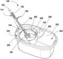
- FIG. 1illustrates a top front perspective view of a mop system according to aspects described herein;
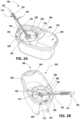
- FIGS. 2 A- 2 Billustrates partial perspective views of the mop system of FIG. 1 with a mop assembly engaged with a wringer basket of the bucket according to aspects described herein;
- FIG. 3illustrates a bottom front perspective view of a mop assembly of the mop system of FIG. 1 according to aspects described herein;
- FIG. 4illustrates an partial top perspective view of the mop of FIG. 3 according to aspects described herein;
- FIG. 5illustrates a cross-sectional side view of a portion of the mop of FIG. 4 according to aspects described herein;
- FIG. 6illustrates a cross-sectional side view of a portion of the mop of FIG. 4 according to aspects described herein;
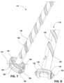
- FIG. 7illustrates a partial perspective view of a portion of the mop of FIG. 3 with some components removed for clarity according to aspects described herein;
- FIG. 8illustrates a partial perspective view of a spiral member of the mop of FIG. 3 according to aspects described herein;
- FIG. 9illustrates a perspective view of a swivel member of the mop of FIG. 3 according to aspects described herein;
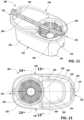
- FIG. 10illustrates a front top perspective view of a bucket assembly of the mop system of FIG. 1 according to aspects described herein;
- FIG. 11illustrates a rear top perspective view of the bucket assembly of FIG. 10 according to aspects described herein;
- FIG. 12illustrates a top view of the bucket assembly of FIG. 10 according to aspects described herein;
- FIG. 13illustrates a side cross-sectional view of the bucket assembly along line 13 - 13 shown in FIG. 12 according to aspects described herein;
- FIG. 14illustrates a perspective cross-sectional view of the bucket assembly along line 14 - 14 shown in FIG. 12 according to aspects described herein;
- FIG. 15illustrates an enlarged view of the bucket assembly of FIG. 14 according to aspects described herein;
- FIG. 16illustrates a top cross-sectional view of the bucket assembly along line 16 - 16 of FIG. 13 according to aspects described herein;
- FIG. 17illustrates a perspective view of the bucket of the bucket assembly of FIG. 10 according to aspects described herein.
- “Plurality,” as used herein,indicates any number greater than one, either disjunctively or conjunctively, as necessary, up to an infinite number.
- first line, segment, plane, edge, surface, etc.is approximately (in this instance, within 5%) orthogonal with another line, plane, edge, surface, etc., over at least 50% of the length of the first line, segment, plane, edge, surface, etc.
- Generally planarmeans that a surface is level and aligned with another surface, such that the two surfaces form a substantially flat single surface, within a tolerance of +/ ⁇ 0.05 inches.
- this disclosurerelates to a mop system comprising a spin mop and a bucket assembly where the spin mop engages the bucket assembly to assist in dewatering the mop.
- the spinning of the mop headmay cause the wringer basket to spin with it, which causes excess water to be forced from the yarns of the mop head. Therefore, dewatering the mop head and preparing it for use.
- the mop headmay be configured to pivot along two different axes to allow a movement of the handle assembly to drive the rotation of the wringer basket even when the handle assembly is arranged at different angles relative to the mop head.
- the mop system 100may include a spin mop assembly 110 and a bucket assembly 200 , where the spin mop 110 engages a wringer basket 280 of the bucket assembly 200 to dewater a mop head 115 .
- the spin mop 110may include a mop base 120 that releasably engages a mop head 115 that includes yarns or other cleaning surface(s).
- the spin mop 110may have a drive mechanism to cause the mop base 120 and the attached mop head 115 to rotate relative to a handle assembly 180 of the mop 110 .
- the handle assembly 180may define a handle longitudinal axis 183 .
- the drive mechanismmay include a spiral member 140 that is slidably engaged with the handle assembly 180 and pivotally engaged with a swivel member 160 .
- the swivel member 160may be pivotally engaged with the spiral member 140 and may be positioned between the spiral member 140 and the mop base 120 .
- the bucket assembly 200may include a bucket 220 to hold a cleaning solution, a bucket handle 296 , a wringer basket 280 that is rotatably engaged with an axle member 230 of the bucket 220 , and cover 250 that secures to the bucket 220 and helps retain the wringer basket 280 to the bucket assembly 200 .
- the spin mop 110may be received in and engage the wringer basket 280 to assist in dewatering the mop head 115 to ensure the mop head 115 has the desired moisture content for the intended cleaning task.
- the mop head 115may be placed into the wringer basket 280 , where the mop base 120 may engage the wringer basket 280 .
- a lever 190may be moved (i.e. rotated or lifted) to a released position to release a brake bushing that allows the handle tube 182 of the handle assembly 180 to slidably move along the spiral member 140 .
- a moving bushing within the handle assembly 180may move along the spiral member 140 causing the spiral member 140 to rotate.
- the moving bushingmay engage the spiral member 140 as the moving bushing is moving downward toward the mop head 115 and may disengage when moving upwards away from the mop head 115 so the rotation of mop head 115 is maintained in one direction.
- the spiral member 140causes the swivel member 160 to rotate, which in turn causes the mop base 120 and the mop head 115 to spin.
- the spinning of the mop base 120 and mop head 115then causes the wringer basket 280 to spin in the same direction as the rotation of the mop base 120 creating a centrifugal force to cause any excess cleaning solution, or liquid, to be forced from the yarns of the mop head 115 .
- the handle assembly 180may be positioned at a variety of angles with the mop base 120 and the axle axis 232 of the axle member 230 of the bucket 220 and still be able to drive the rotation of the mop head 115 from multiple angles.
- the handle assembly 180may be pivotally rotated about a first swivel axis 170 with a first angle having a range between 0 and 90 degrees from the axle axis 232 and may also be pivotally rotated about the second swivel axis 176 to a second angle within a second angle range of 0 degrees and 61 degrees, while still being able to slide along the spiral member 140 to rotate the mop base 120 and subsequently rotate the wringer basket 280 .
- the handle assembly 180may operate primarily when the handle assembly is pivotally rotated about a first swivel axis with a first angle range of 0 and 45 degrees and where the handle assembly 180 may also concurrently be pivoted about the second swivel axis 176 within a second angle range between a 0 degrees and 45 degrees.
- the second angle rangemay be between 1 degree and 45 degrees.
- the mop assembly 110may include a first end 112 , and a second end 114 opposite the first end 112 , where a mop head 115 used for cleaning surfaces is located at the first end 112 and a hanger tip 196 is arranged at the second end 114 .
- the mop head 115may be releasably connected to the mop base 120 via the frame 130 .
- the frame 130may have a plurality of receivers 132 arranged along a bottom surface 134 of the frame 130 that may releasably connect to a corresponding member of the mop head 115 to secure the mop head 115 to the mop base 120 .
- receivers 132may include a snap-fit connection to allow the mop head 115 to be removed from the mop base 120 after use, such that the mop head 115 may be cleaned or replaced with another mop head 115 .
- the handle assembly 180may be lowered over the spiral member 140 and then locked in place by moving the lever 190 to the locked position.
- the mop assembly 110may include a drive mechanism that allows movement of the handle assembly 180 relative to a spiral member 140 to cause rotation of the mop base 120 relative to the handle assembly 180 .
- the spiral member 140may include an engaging member 144 at a first end 142 , a second end 146 opposite the first end 142 , and a central spiraled portion 150 extending between the first end 142 and the second end 146 .
- the spiraled portion 150may have a spiraled surface that extends a majority of the length of the central spiraled portion 150 .
- the handle assembly 180may include a handle tube 182 , a handle grip 184 near the lower end of the handle tube 182 , a lever 190 attached to the handle grip 184 .
- the lever 190may engage a brake bushing within the handle tube 182 , where the lever 190 has a locked positioned that prevents the handle assembly 180 from moving relative to the spiral member 140 and an unlocked position that releases the brake bushing and a sliding bushing (also located within the handle tube 182 ), which allows the brake bushing and the sliding bushing along with the handle assembly 180 to slide downward on the spiral member 140 .
- the lever 190may engage the brake bushing by compressing flexible fingers on the brake bushing to prevent the handle tube 182 from moving relative to the spiral member 140 . As these components move along the spiraled surface of the spiral member 140 , the spiral member 140 rotates causing the mop base 120 to spin.
- the mop base 120may engage the wringer basket 280 of the bucket assembly 200 to transmit the rotation of the mop base 120 to cause the rotation of the wringer basket 280 .
- the mop base 120may be received by the wringer basket 280 .
- the wringer basket 280may have a plurality of tabs 288 that extend upward and/or inward from a perimeter wall 284 the wringer basket 280 that contact either an outer perimeter surface 124 and/or a chamfered lower outward facing surface 126 of the mop base 120 . This contact between the outer perimeter surface 124 and/or the chamfered lower outward facing surface 126 may help the mop base 120 .
- Each tab 288may have a tapered portion 289 extending near or from an upper edge of the wringer basket 280 .
- the tapered portion 289 of each tab 288may help to guide the mop base 120 onto a shelf portion 290 of each tab that extends generally perpendicular to the axle axis 232 .
- a plurality of the shelf portions 290 of plurality of tabs 288may combine to form a generally planar surface to support and engage the mop base 120 when it is received in the wringer basket 280 . This engagement may also help the mop base 120 transmit the rotational force to the wringer basket 280 .
- the plurality of tabs 288may be uniformly spaced apart around the circumference of the basket 280 .
- the plurality tabs 288may be an even number of tabs 288 (such as the 8 tabs spaced approximately 45 degrees apart from each other in the illustrated example) or may have an odd number of tabs 288 (such as 3 tabs spaced approximately 120 degrees apart).
- the wringer basket 280may have any number of tabs 288 and the tabs may not be uniformly spaced.
- FIGS. 4 - 6illustrate a portion of the mop 110 focusing on the articulating joint of the mop base 120 relative to the spiral member 140 .
- the mop base 120may articulate about two different axes while still allowing the handle assembly 180 to drive rotation of the mop base 120 .
- the spiral member 140includes an engaging member 144 , where the engaging member may have a body member 148 with a width greater than the spiraled portion 150 of the spiral member 140 , which may act as a stop for the handle assembly 180 when the handle assembly 180 moves toward the mop base 120 .
- the body membermay include a boss 152 that extends from opposite ends of the body member 148 .
- the body member 148 of the engaging member 144may be received in a central aperture 162 of the swivel member 160 where each boss 152 may be inserted into a corresponding opening 164 that are arranged opposite each other on a perimeter surface 166 of the swivel member 160 .
- the bosses 152may align with a first swivel axis 170 .
- the engaging member 144may be pivotally connected to the swivel member 160 to rotate about the first swivel axis 170 that is defined by the openings 164 .
- the swivel member 160may be generally oval shaped have a top surface 161 , a bottom surface 163 , and convex shaped perimeter surface 166 extending between the top and bottom surfaces 161 , 163 .
- a pair of swivel bosses 168may be arranged on opposite ends of the perimeter surface 166 .
- the bosses 168may define a second swivel axis 176 that may extend in a direction generally perpendicular to the first swivel axis 170 .
- the second swivel axis 176may be arranged at an angle that is not generally perpendicular but different from the first swivel axis 170 .
- Each boss 168may be inserted into a corresponding opening 128 of the mop base 120 to pivotally connect the swivel member 160 to the mop base 120 around the second swivel axis 176 .
- mop base 120may have a recess 122 with a generally curved concave shaped surface to allow the swivel member 160 to move within the recess 122 .
- the handle assembly 180may be slidably connected to and arranged in a collinear fashion with the spiral member 140 . The handle assembly 180 may slide over the spiral member 140 such that the spiral member is inside the handle assembly 180 .
- the two pivotally connected members 140 , 160allow the handle assembly 180 to be rotated along both axes 170 , 176 at the same time while still allowing movement of the handle assembly 180 along the spiral member 140 to drive the rotation of the mop base 120 around the axle axis 232 .
- the movement of the handle assembly 180 along the spiral member 140causes the mop base 120 to rotate which in turn rotates the mop head and wringer basket 280 to rotate in the same direction as the mop base 120 .
- the wateris forced from the wet mop head 115 into the bucket assembly 200 .
- the watermay contact the rear surface of splashguard 260 of the cover 250 and then fall into the bucket 220 .
- the splashguard 260 of the cover 250may be uniquely shaped to prevent water from splashing out of the bucket assembly 200 .
- the bucket assembly 200may be partitioned into a wringer region 202 and a storage portion 204 , and may include a bucket 220 , a cover 250 , a wringer basket 280 , and a handle 296 .
- the bucket 220may have an elongated shape that includes a top wall 222 , a bottom wall 224 opposite the top wall 222 , and a sidewall 226 extending between the top wall 222 and the bottom wall 224 .
- the sidewall 226 and bottom wall 224may create a cavity 228 for holding a substance (i.e. a cleaning solution or other liquid material).
- elongated shape of the bucketmay include a length that is greater than a width, where the length extends from a first side 234 to a second side 236 opposite the first side 234 and the width extends from a third side 238 to a fourth side 240 opposite the third side 238 .
- the wringer region 202may include the wringer basket 280 and cover 250 that are arranged nearer the first side 234 , while the storage portion 204 that is configured to hold the majority of the liquid is nearer the second side 236 .
- a handle 296may be rotatably connected to the top wall 222 at the first side 234 and the second side 236 to provide a user an easy means to carry the bucket assembly 200 .
- the wringer basket 280may be rotationally engaged with an axle member 230 of the bucket 220 , such that the wringer basket 280 is free to spin on the axle member 230 of the bucket 220 .
- the axle member 230may extend from the bottom wall 224 and define an axle axis 232 .
- the axle axis 232may be vertically oriented or generally perpendicular with the bottom wall 224 .
- the wringer basket 280may have a bottom wall 282 , a perimeter wall 284 extending upward from the bottom wall 282 , with a plurality of tabs 288 extending from the perimeter wall 284 .
- the walls 282 , 284may have a plurality of openings 286 extending through the walls 282 , 284 that allow water to pass through the openings 286 .
- the openings 286may be elongated with a height greater than a width.
- the wringer basket 280may include a receiver 294 on the bottom wall 282 that rotationally engages the axle member 230 to allow the wringer basket 280 to freely rotate around axle axis 232 .
- the wringer basket 280may be secured to the bucket assembly 200 by cover 250 , where the cover 250 is mounted onto a shelf 242 that extends along the first side 234 , a portion of the third side 238 , and a portion of the fourth side 240 of the bucket assembly 200 .
- the shelf 242may be positioned below the top wall 222 and have a plurality of locking features 244 (i.e. pockets and raised protrusions) that engage with corresponding locking features on the underside of the cover 250 to secure the cover 250 to the bucket 220 .
- the cover 250may have a central opening 252 with a flange 254 that extends downward from a top surface 256 of the cover 250 .
- the flange 254may overlap with an outer edge 292 of the wringer basket 280 causing the central opening 252 to have a width that is smaller than a width of the outer edge 292 of the wringer basket 280 .
- the cover 250may also include splashguard 260 that extends downward from the top surface 256 toward the bottom wall 224 and may serve as a partition between the wringer region 202 and the storage portion 204 .
- the splashguardmay help to create a collection region 268 around the wringer basket 280 to prevent liquid from escaping the bucket assembly 200 while the wringer basket 280 is spinning. While the top surface 256 of the cover 250 may extend over this collection region 268 helps to prevent liquid from escaping.
- the splashguard 260may have an asymmetrical shape with respect to a plane 270 defined by an intersection of axle axis 232 and the center line of the bucket base (i.e.
- the splashguard 260may have a central region 262 that has a curved shape that may be coaxial with axle axis 232 .
- the curved shape of the central region 262may be a convex shape.
- the splashguard 260may also have a first end region 264 and a second end region 266 that extend from the central region 262 opposite the first end region 264 , where each end region 264 , 266 that extends both toward the second side 236 of the bucket 220 and also outward from the central convex region 262 to the sidewall 226 on the third side 238 and fourth side 240 respectively.
- the first end region 264may have a different shape than the second end region 266 . As shown in FIG. 17 , the first end region 264 may have a smaller radius 272 in the corner as it transitions from the central convex region 262 than radius 274 in the corner of the transition between the central convex region 262 and the second end region 266 . In addition, first end region 264 may have an extended wall 265 that creates a narrow cavity 276 within the collection region 268 that extends toward the second side 236 of the bucket assembly 200 to improve the splashguard's retention of expelled liquid.
- An upper side edge 267 of the extended wall 265may contact an inner surface of the sidewall 226 to prevent liquid from escaping while a lower edge 269 of the extended wall 265 may be offset from the inner surface of the sidewall 226 to allow liquid to fall into the storage portion 204 of the bucket assembly 200 .
- the first end region 264may extend further toward the second side 236 than the second end region 266 (i.e. the extended wall 265 has an end point further from the axle axis 232 than an end point of the second end region 266 ).
- the splashguard 260may extend at least 50 percent of a height of the bucket 220 , where the height of the bucket assembly may be defined as a distance from a bottom surface of the bottom wall to a top surface of the top wall.
- the unique shape of the splashguard 260may be arranged to stop any water droplets expelled from the wringer basket 280 that may be propelled toward the storage portion 204 .
- the wringer basket 280may rotate in a clockwise direction (as viewed in a top view shown in FIG. 12 ). As the wringer basket 280 rotates, the expelled water is directed toward a quadrant of the bucket near both the second side 236 and the third side 238 of the bucket assembly 200 .
- the first end region 264 with its extended wall 265may help to catch any liquid expelled from the mop head 115 and allow it to drip down the splashguard 260 and into the storage portion 204 .
- the sidewall 226may have a pour spout 246 arranged at the second side 236 of the bucket 220 .
- the pour spout 246may have be located below the top wall 222 of the bucket base and allow a user to easily tilt the bucket assembly 200 to pour out any cleaning solution (or water) from the bucket assembly 200 .
- the sidewall 226may have a tapered shape to act as a funnel to assist the flow of water through the spout 246 .
- the various components of the mop system 100such as the mop base 120 , the spiral member 140 , the swivel member 160 , the components of the handle assembly 180 , the bucket 220 , the cover 250 , the wringer basket 280 , and the handle 296 may be formed from a non-metallic material, such as a polymeric material, using a molding, forming, cutting, or other process known to one skilled in the art.
- a non-metallic materialsuch as a polymeric material
- any or all of these componentsmay be formed from a metallic material.
Landscapes
- Engineering & Computer Science (AREA)
- Mechanical Engineering (AREA)
- Cleaning Implements For Floors, Carpets, Furniture, Walls, And The Like (AREA)
Abstract
Description
Claims (18)
Priority Applications (5)
| Application Number | Priority Date | Filing Date | Title |
|---|---|---|---|
| US17/235,679US11717130B2 (en) | 2021-04-20 | 2021-04-20 | Mop system with rotating mop head |
| CN202210395588.XACN115211781B (en) | 2021-04-20 | 2022-04-14 | Mopping system with rotating mop head |
| CA3155400ACA3155400A1 (en) | 2021-04-20 | 2022-04-14 | Mop system with rotating mop head |
| AU2022202613AAU2022202613A1 (en) | 2021-04-20 | 2022-04-20 | Mop system with rotating mop head |
| US18/210,905US20230404354A1 (en) | 2021-04-20 | 2023-06-16 | Mop System with Rotating Mop Head |
Applications Claiming Priority (1)
| Application Number | Priority Date | Filing Date | Title |
|---|---|---|---|
| US17/235,679US11717130B2 (en) | 2021-04-20 | 2021-04-20 | Mop system with rotating mop head |
Related Child Applications (1)
| Application Number | Title | Priority Date | Filing Date |
|---|---|---|---|
| US18/210,905ContinuationUS20230404354A1 (en) | 2021-04-20 | 2023-06-16 | Mop System with Rotating Mop Head |
Publications (2)
| Publication Number | Publication Date |
|---|---|
| US20220330784A1 US20220330784A1 (en) | 2022-10-20 |
| US11717130B2true US11717130B2 (en) | 2023-08-08 |
Family
ID=83602010
Family Applications (2)
| Application Number | Title | Priority Date | Filing Date |
|---|---|---|---|
| US17/235,679Active2041-09-23US11717130B2 (en) | 2021-04-20 | 2021-04-20 | Mop system with rotating mop head |
| US18/210,905PendingUS20230404354A1 (en) | 2021-04-20 | 2023-06-16 | Mop System with Rotating Mop Head |
Family Applications After (1)
| Application Number | Title | Priority Date | Filing Date |
|---|---|---|---|
| US18/210,905PendingUS20230404354A1 (en) | 2021-04-20 | 2023-06-16 | Mop System with Rotating Mop Head |
Country Status (4)
| Country | Link |
|---|---|
| US (2) | US11717130B2 (en) |
| CN (1) | CN115211781B (en) |
| AU (1) | AU2022202613A1 (en) |
| CA (1) | CA3155400A1 (en) |
Cited By (8)
| Publication number | Priority date | Publication date | Assignee | Title |
|---|---|---|---|---|
| USD1026468S1 (en)* | 2023-12-19 | 2024-05-14 | Xun Zheng | Cleaning brush |
| USD1028525S1 (en)* | 2024-02-05 | 2024-05-28 | Yunlong Li | Electric spin scrubber |
| USD1035205S1 (en)* | 2023-05-05 | 2024-07-09 | Langfang Michao Trading Co., Ltd. | Mop bucket |
| USD1036864S1 (en)* | 2022-06-06 | 2024-07-30 | Shenzhen MaiGeSaiFu Technology Co., Ltd. | Spin scrubber |
| USD1040524S1 (en)* | 2022-06-20 | 2024-09-03 | Shenzhen Zhiliang Technology Co., Ltd | Electric spin scrubber |
| USD1046465S1 (en)* | 2024-02-05 | 2024-10-15 | Yunlong Li | Electric spin scrubber |
| USD1055526S1 (en)* | 2022-09-13 | 2024-12-31 | Zhongshan Kamshing Home Electrical Appliance Co., Ltd | Cleaning brush |
| USD1085604S1 (en)* | 2025-03-30 | 2025-07-22 | Shenzhen Zero Zero Hair Automotive Supplies Co., Ltd | Car wash mop |
Families Citing this family (1)
| Publication number | Priority date | Publication date | Assignee | Title |
|---|---|---|---|---|
| US12245732B2 (en) | 2023-05-03 | 2025-03-11 | The Libman Company | Grip handle assembly for a mop |
Citations (64)
| Publication number | Priority date | Publication date | Assignee | Title |
|---|---|---|---|---|
| US1722130A (en) | 1928-08-16 | 1929-07-23 | Finstad Thea | Mop pail with wringing attachment |
| US1882918A (en) | 1931-12-23 | 1932-10-18 | Ralph H Robb | Mop wringer |
| US3040356A (en) | 1960-06-29 | 1962-06-26 | Peter S Vosbikian | Dust mops with means to manually spin the mophead |
| USD344379S (en) | 1992-06-17 | 1994-02-15 | Emsco, Inc. | Combined portable mop bucket and cover with wringer |
| USD345236S (en) | 1992-06-29 | 1994-03-15 | Sin-Hsiung Chen | Mops wringer |
| US5414892A (en) | 1992-07-29 | 1995-05-16 | Emsco, Inc. | Mop bucket cover having wringer and storage device |
| USD417935S (en) | 1997-09-09 | 1999-12-21 | Entreprises Hamelin | Double container bucket |
| USD482530S1 (en) | 2003-05-05 | 2003-11-25 | Leeretta Evans | Battery powered scrub brush with telescopic handle |
| US20070226929A1 (en) | 2006-03-28 | 2007-10-04 | Ta-Chun Kao | Wringable mop |
| USD557472S1 (en) | 2006-05-17 | 2007-12-11 | Leifheit Ag | Bucket |
| US7318247B2 (en) | 2003-03-27 | 2008-01-15 | The Libman Company | Bucket combination |
| USD603115S1 (en) | 2008-11-13 | 2009-10-27 | Bissell Homecare, Inc. | High reach duster |
| US20100180460A1 (en)* | 2009-01-22 | 2010-07-22 | Jack Tang | Mop dehydrating apparatus |
| EP2255712A2 (en) | 2009-05-27 | 2010-12-01 | Tuo Shen International Corporation Limited | Telescopically rotatable mop |
| US20110225752A1 (en) | 2010-03-16 | 2011-09-22 | Tsung-Mou Yu | Mop with spinning device |
| US20110247163A1 (en) | 2010-04-08 | 2011-10-13 | I-Huang Chen | Self-rotating mop |
| US20110271472A1 (en) | 2010-05-07 | 2011-11-10 | Mei Ling Yang | Mop Disc And Fabric Frame Fixation Structure |
| US20110274481A1 (en) | 2009-07-01 | 2011-11-10 | Tuo Shen International Corporation Limited | Swiveling locking mechanism of a telescopic rod of a mop |
| US20110271475A1 (en) | 2010-05-07 | 2011-11-10 | Mei Ling Yang | Mop Structure of Converting Vertical Linear Displacement Into Unidirectional Rotation For Dewatering a Mop |
| US20120047675A1 (en)* | 2010-08-25 | 2012-03-01 | Shu-Hsun Chu | Dual-purpose spin dry mop bucket |
| US8132287B2 (en) | 2007-11-30 | 2012-03-13 | Dikai International Enterprise Co., Ltd. | Cleaning device with cleaning means and a frame body |
| US8214963B2 (en) | 2009-05-14 | 2012-07-10 | Tsung Mou Yu | Mop with spinning device |
| US8220101B2 (en) | 2009-12-29 | 2012-07-17 | Tuo Shen International Corporation Limited | Telescopically rotatable mop |
| US8291544B2 (en) | 2009-07-01 | 2012-10-23 | Tuo Shen International Corporation Limited | Mop with the function of dewatering the yarns by twisting in a single direction via an up-and-down linear motion |
| US8316502B2 (en) | 2011-01-11 | 2012-11-27 | Guofa Shao | Spin dry mop |
| US8327502B2 (en)* | 2010-03-19 | 2012-12-11 | Yao-Feng Tsai | Centrifugal dehydrating device for mop |
| US8336160B2 (en)* | 2011-01-28 | 2012-12-25 | Ching-Ming Chen | Dual rotating dewater bucket and mop thereof |
| US8365341B2 (en)* | 2010-10-18 | 2013-02-05 | Dikai International Enterprise Co., Ltd. | Mop assembly |
| WO2013052439A2 (en) | 2011-10-08 | 2013-04-11 | 3M Innovative Properties Company | Manual rotation driving unit and spin dehydrating mop |
| US8544133B2 (en) | 2005-04-26 | 2013-10-01 | Leifheit Ag | Mopping device with a multi-turn actuator |
| WO2013151784A1 (en) | 2012-04-01 | 2013-10-10 | 3M Innovative Properties Company | Basket-less cleaning tool set |
| USD693080S1 (en) | 2012-12-24 | 2013-11-05 | Guofa Shao | Spin mop bucket |
| USD694978S1 (en) | 2013-03-01 | 2013-12-03 | The Libman Company | Bucket |
| USD707003S1 (en) | 2012-12-12 | 2014-06-10 | Carl Freudenberg Kg | Bucket |
| US8793834B2 (en)* | 2010-12-30 | 2014-08-05 | Rock Tone Enterprise Co. Ltd. | Mop cleaning set |
| US8819890B2 (en) | 2013-01-18 | 2014-09-02 | Dikai International Enterprise Co., Ltd. | Rotational structure |
| US8925139B2 (en) | 2012-08-03 | 2015-01-06 | Chin-Yang Shih | Swivel mop with revolving dehydration function |
| WO2015010577A1 (en) | 2013-07-25 | 2015-01-29 | 嘉兴捷顺旅游制品有限公司 | Rotatable spin-dry mop |
| US8959697B2 (en) | 2010-10-20 | 2015-02-24 | Tsung-Mou Yu | Mop with spinning device |
| USD723758S1 (en) | 2014-05-20 | 2015-03-03 | Telebrands, Corp. | Dual spout mop bucket |
| US8974194B2 (en) | 2011-12-09 | 2015-03-10 | Sunonwealth Electric Machine Industry Co., Ltd. | Advection-type fan and an impeller thereof |
| US8978194B1 (en) | 2014-04-28 | 2015-03-17 | Telebrands Corp. | Rotating mop handle and bucket assembly |
| USD727580S1 (en) | 2014-04-15 | 2015-04-21 | Lou Lentine | Mop bucket |
| US9021648B1 (en) | 2014-05-16 | 2015-05-05 | Maxplus Industries Company Limited | Strength-saving spiral mop pole |
| USD728882S1 (en) | 2013-09-26 | 2015-05-05 | Guang'an Zeng | Mop bucket |
| US20150128373A1 (en)* | 2013-11-12 | 2015-05-14 | Dikai International Enterprise Co., Ltd. | Dewatering bucket set |
| US9032579B1 (en) | 2013-07-31 | 2015-05-19 | Cheng Kai Chen | Spin mop |
| US20160206171A1 (en) | 2015-01-15 | 2016-07-21 | Freudenberg Household Products Lp | Twist mop with integral pawl |
| US20160316984A1 (en) | 2015-04-30 | 2016-11-03 | Jiaxing Jackson Travel Products Co., Ltd. | Self-wringing flat mop |
| USD789638S1 (en) | 2015-12-17 | 2017-06-13 | Carl Freudenberg Kg | Bucket |
| USD819906S1 (en) | 2017-05-08 | 2018-06-05 | Town & Country Linen Corp. | Telescopic handle |
| US20180344125A1 (en) | 2017-06-06 | 2018-12-06 | I-Chang Chen | Rotatable vibration mop |
| USD849347S1 (en) | 2018-01-08 | 2019-05-21 | Helen Of Troy Limited | Floor duster |
| USD853670S1 (en) | 2018-12-20 | 2019-07-09 | Shenzhen Qianhai Patuoxun Network And Technology Co., Ltd | Telescopic rod |
| USD865309S1 (en) | 2016-11-17 | 2019-10-29 | Viatek Hong Kong Limited | Double sided mop |
| US20190390852A1 (en) | 2018-06-21 | 2019-12-26 | Roy Allen Sigurdson | Lighted Sports Court Floor Mop |
| USD875339S1 (en) | 2017-09-06 | 2020-02-11 | Carl Freudenberg Kg | Mop handle |
| USD903211S1 (en) | 2020-07-23 | 2020-11-24 | Hongtao Gao | Dog pooper scooper rod |
| US20210186295A1 (en) | 2019-12-19 | 2021-06-24 | Tylor Christian ROSS | Mop with Interchangeable Head Mechanisms |
| USD925850S1 (en) | 2019-03-13 | 2021-07-20 | Carl Freudenberg Kg | Mop or broom handle |
| USD927195S1 (en) | 2020-10-16 | 2021-08-10 | Shenzhen Qianhai Patuoxun Network And Technology Co., Ltd | Scrubbing cleaning brush |
| USD935719S1 (en) | 2020-08-19 | 2021-11-09 | Jierong Huang | Floor mop |
| USD936303S1 (en) | 2019-11-08 | 2021-11-16 | Yan Jiang | Pet poop rake |
| USD936304S1 (en) | 2019-11-08 | 2021-11-16 | Yan Jiang | Pet poop spade |
Family Cites Families (5)
| Publication number | Priority date | Publication date | Assignee | Title |
|---|---|---|---|---|
| CN1845696A (en)* | 2003-09-03 | 2006-10-11 | 宝洁公司 | multipurpose cleaning tool |
| US7854035B2 (en)* | 2005-11-03 | 2010-12-21 | 3M Innovative Properties Company | Dual-sided flip mop |
| CN201445482U (en)* | 2009-05-18 | 2010-05-05 | 赵立民 | Mop with the angles of the handle and the mop head freely adjustable |
| US8112840B2 (en)* | 2009-07-01 | 2012-02-14 | Tuo Shen International Corporation Limited | Disc rotating and positioning structure of a mop |
| CN101884516B (en)* | 2010-07-08 | 2014-12-03 | 赵一美 | A kind of mop bucket and its matching mop |
- 2021
- 2021-04-20USUS17/235,679patent/US11717130B2/enactiveActive
- 2022
- 2022-04-14CACA3155400Apatent/CA3155400A1/enactivePending
- 2022-04-14CNCN202210395588.XApatent/CN115211781B/enactiveActive
- 2022-04-20AUAU2022202613Apatent/AU2022202613A1/enactivePending
- 2023
- 2023-06-16USUS18/210,905patent/US20230404354A1/enactivePending
Patent Citations (73)
| Publication number | Priority date | Publication date | Assignee | Title |
|---|---|---|---|---|
| US1722130A (en) | 1928-08-16 | 1929-07-23 | Finstad Thea | Mop pail with wringing attachment |
| US1882918A (en) | 1931-12-23 | 1932-10-18 | Ralph H Robb | Mop wringer |
| US3040356A (en) | 1960-06-29 | 1962-06-26 | Peter S Vosbikian | Dust mops with means to manually spin the mophead |
| USD344379S (en) | 1992-06-17 | 1994-02-15 | Emsco, Inc. | Combined portable mop bucket and cover with wringer |
| USD345236S (en) | 1992-06-29 | 1994-03-15 | Sin-Hsiung Chen | Mops wringer |
| US5414892A (en) | 1992-07-29 | 1995-05-16 | Emsco, Inc. | Mop bucket cover having wringer and storage device |
| USD417935S (en) | 1997-09-09 | 1999-12-21 | Entreprises Hamelin | Double container bucket |
| US7318247B2 (en) | 2003-03-27 | 2008-01-15 | The Libman Company | Bucket combination |
| USD482530S1 (en) | 2003-05-05 | 2003-11-25 | Leeretta Evans | Battery powered scrub brush with telescopic handle |
| US8544133B2 (en) | 2005-04-26 | 2013-10-01 | Leifheit Ag | Mopping device with a multi-turn actuator |
| US20070226929A1 (en) | 2006-03-28 | 2007-10-04 | Ta-Chun Kao | Wringable mop |
| USD557472S1 (en) | 2006-05-17 | 2007-12-11 | Leifheit Ag | Bucket |
| US8132287B2 (en) | 2007-11-30 | 2012-03-13 | Dikai International Enterprise Co., Ltd. | Cleaning device with cleaning means and a frame body |
| USD603115S1 (en) | 2008-11-13 | 2009-10-27 | Bissell Homecare, Inc. | High reach duster |
| US20100180460A1 (en)* | 2009-01-22 | 2010-07-22 | Jack Tang | Mop dehydrating apparatus |
| US8214963B2 (en) | 2009-05-14 | 2012-07-10 | Tsung Mou Yu | Mop with spinning device |
| EP2255712A2 (en) | 2009-05-27 | 2010-12-01 | Tuo Shen International Corporation Limited | Telescopically rotatable mop |
| US20110274481A1 (en) | 2009-07-01 | 2011-11-10 | Tuo Shen International Corporation Limited | Swiveling locking mechanism of a telescopic rod of a mop |
| US8291544B2 (en) | 2009-07-01 | 2012-10-23 | Tuo Shen International Corporation Limited | Mop with the function of dewatering the yarns by twisting in a single direction via an up-and-down linear motion |
| US8522387B2 (en) | 2009-07-01 | 2013-09-03 | Tuo Shen International Corporation Limited | Swiveling locking mechanism of a telescopic rod of a mop |
| US8220101B2 (en) | 2009-12-29 | 2012-07-17 | Tuo Shen International Corporation Limited | Telescopically rotatable mop |
| US8407845B2 (en) | 2010-03-16 | 2013-04-02 | Tsung-Mou Yu | Mop with spinning device |
| US20110225752A1 (en) | 2010-03-16 | 2011-09-22 | Tsung-Mou Yu | Mop with spinning device |
| US8327502B2 (en)* | 2010-03-19 | 2012-12-11 | Yao-Feng Tsai | Centrifugal dehydrating device for mop |
| US20110247163A1 (en) | 2010-04-08 | 2011-10-13 | I-Huang Chen | Self-rotating mop |
| US20110271475A1 (en) | 2010-05-07 | 2011-11-10 | Mei Ling Yang | Mop Structure of Converting Vertical Linear Displacement Into Unidirectional Rotation For Dewatering a Mop |
| US20110271472A1 (en) | 2010-05-07 | 2011-11-10 | Mei Ling Yang | Mop Disc And Fabric Frame Fixation Structure |
| US8225454B2 (en)* | 2010-05-07 | 2012-07-24 | Mackay Electronic Co., Ltd. | Mop disc and fabric frame fixation structure |
| US8291538B2 (en) | 2010-05-07 | 2012-10-23 | Mackay Electronic Co., Ltd. | Mop structure of converting vertical linear displacement into unidirectional rotation for dewatering a mop |
| US20120047675A1 (en)* | 2010-08-25 | 2012-03-01 | Shu-Hsun Chu | Dual-purpose spin dry mop bucket |
| US8365341B2 (en)* | 2010-10-18 | 2013-02-05 | Dikai International Enterprise Co., Ltd. | Mop assembly |
| US8959697B2 (en) | 2010-10-20 | 2015-02-24 | Tsung-Mou Yu | Mop with spinning device |
| US8826487B2 (en)* | 2010-12-30 | 2014-09-09 | Rock Tone Enterprise Co. Ltd. | Mop cleaning set |
| US8826486B2 (en)* | 2010-12-30 | 2014-09-09 | Rock Tone Enterprise Co. Ltd. | Mop cleaning set |
| US8793834B2 (en)* | 2010-12-30 | 2014-08-05 | Rock Tone Enterprise Co. Ltd. | Mop cleaning set |
| US8316502B2 (en) | 2011-01-11 | 2012-11-27 | Guofa Shao | Spin dry mop |
| US8336160B2 (en)* | 2011-01-28 | 2012-12-25 | Ching-Ming Chen | Dual rotating dewater bucket and mop thereof |
| WO2013052439A2 (en) | 2011-10-08 | 2013-04-11 | 3M Innovative Properties Company | Manual rotation driving unit and spin dehydrating mop |
| US8974194B2 (en) | 2011-12-09 | 2015-03-10 | Sunonwealth Electric Machine Industry Co., Ltd. | Advection-type fan and an impeller thereof |
| WO2013151784A1 (en) | 2012-04-01 | 2013-10-10 | 3M Innovative Properties Company | Basket-less cleaning tool set |
| US8925139B2 (en) | 2012-08-03 | 2015-01-06 | Chin-Yang Shih | Swivel mop with revolving dehydration function |
| USD707003S1 (en) | 2012-12-12 | 2014-06-10 | Carl Freudenberg Kg | Bucket |
| USD693080S1 (en) | 2012-12-24 | 2013-11-05 | Guofa Shao | Spin mop bucket |
| US8819890B2 (en) | 2013-01-18 | 2014-09-02 | Dikai International Enterprise Co., Ltd. | Rotational structure |
| USD694978S1 (en) | 2013-03-01 | 2013-12-03 | The Libman Company | Bucket |
| WO2015010577A1 (en) | 2013-07-25 | 2015-01-29 | 嘉兴捷顺旅游制品有限公司 | Rotatable spin-dry mop |
| US9032579B1 (en) | 2013-07-31 | 2015-05-19 | Cheng Kai Chen | Spin mop |
| USD728882S1 (en) | 2013-09-26 | 2015-05-05 | Guang'an Zeng | Mop bucket |
| US20150128373A1 (en)* | 2013-11-12 | 2015-05-14 | Dikai International Enterprise Co., Ltd. | Dewatering bucket set |
| USD727580S1 (en) | 2014-04-15 | 2015-04-21 | Lou Lentine | Mop bucket |
| US9730568B2 (en) | 2014-04-28 | 2017-08-15 | Telebrands Corp. | Rotating mop handle and bucket assembly |
| US8978194B1 (en) | 2014-04-28 | 2015-03-17 | Telebrands Corp. | Rotating mop handle and bucket assembly |
| US8997305B1 (en) | 2014-04-28 | 2015-04-07 | Telebrands Corp. | Rotating mop handle and bucket assembly |
| US9021648B1 (en) | 2014-05-16 | 2015-05-05 | Maxplus Industries Company Limited | Strength-saving spiral mop pole |
| USD723758S1 (en) | 2014-05-20 | 2015-03-03 | Telebrands, Corp. | Dual spout mop bucket |
| US20160206171A1 (en) | 2015-01-15 | 2016-07-21 | Freudenberg Household Products Lp | Twist mop with integral pawl |
| US20160316984A1 (en) | 2015-04-30 | 2016-11-03 | Jiaxing Jackson Travel Products Co., Ltd. | Self-wringing flat mop |
| USD789638S1 (en) | 2015-12-17 | 2017-06-13 | Carl Freudenberg Kg | Bucket |
| USD804125S1 (en) | 2015-12-17 | 2017-11-28 | Carl Freudenberg Kg | Bucket |
| USD865309S1 (en) | 2016-11-17 | 2019-10-29 | Viatek Hong Kong Limited | Double sided mop |
| USD819906S1 (en) | 2017-05-08 | 2018-06-05 | Town & Country Linen Corp. | Telescopic handle |
| US20180344125A1 (en) | 2017-06-06 | 2018-12-06 | I-Chang Chen | Rotatable vibration mop |
| USD875339S1 (en) | 2017-09-06 | 2020-02-11 | Carl Freudenberg Kg | Mop handle |
| USD849347S1 (en) | 2018-01-08 | 2019-05-21 | Helen Of Troy Limited | Floor duster |
| US20190390852A1 (en) | 2018-06-21 | 2019-12-26 | Roy Allen Sigurdson | Lighted Sports Court Floor Mop |
| USD853670S1 (en) | 2018-12-20 | 2019-07-09 | Shenzhen Qianhai Patuoxun Network And Technology Co., Ltd | Telescopic rod |
| USD925850S1 (en) | 2019-03-13 | 2021-07-20 | Carl Freudenberg Kg | Mop or broom handle |
| USD936303S1 (en) | 2019-11-08 | 2021-11-16 | Yan Jiang | Pet poop rake |
| USD936304S1 (en) | 2019-11-08 | 2021-11-16 | Yan Jiang | Pet poop spade |
| US20210186295A1 (en) | 2019-12-19 | 2021-06-24 | Tylor Christian ROSS | Mop with Interchangeable Head Mechanisms |
| USD903211S1 (en) | 2020-07-23 | 2020-11-24 | Hongtao Gao | Dog pooper scooper rod |
| USD935719S1 (en) | 2020-08-19 | 2021-11-09 | Jierong Huang | Floor mop |
| USD927195S1 (en) | 2020-10-16 | 2021-08-10 | Shenzhen Qianhai Patuoxun Network And Technology Co., Ltd | Scrubbing cleaning brush |
Non-Patent Citations (5)
| Title |
|---|
| Amazon.com_ Libman All-In-One Microfiber Spin Mop https://www.amazon.com/Libman-Bucket-Green-White-Spin/dp/B072Z6VTP2/ref=sr<http://www.amazon.com/Libman-Bucket-Green-White-Spin/dp/B072Z6VTP2/ref%3Dsr_1_2>_1_2 (Year: 2018). |
| Amazon.com_ Spin Mop https://www.amazon.com/Masthome-Wringer-Microfiber-Household-Stai nless/dp/B076JC6TTP/ref=sr <http://www.amazon.com/Masthome-Wringer-Microfiber-Household-Stainless/dp/B076JC6TTP/ref%3Dsr>_1_30_sspa (Year: 2018). |
| homedepot.com Libman Microfiber Tornado Wet Spin Mop and Bucket https://www.homedepot.com/p/Li <http://www.homedepot.com/p/Libman-Microfiber-Tornado-Wet-Spin-Mop-and-Bucket-Floor-Cleaning-System-with-2-Refills-1566/>bman-Microfiber-Tornado-Wet-Spin-Mop-and-Bucket-Floor-Clean <http://www.homedepot.com/p/Libman-Microfiber-Tornado-Wet-Spin-Mop-and-Bucket-Floor-Cleaning-System-with-2-Refills-1566/>ing-System-with-2-Refills-1566/<http://www.homedepot.com/p/Libman-Microfiber-Tornado-Wet-Spin-Mop-and-Bucket-Floor-Cleaning-System-with-2-Refills-1566/321073195. |
| Leifheit Clean Twist Disc Ergo Mop and Bucket Set, retrieved from https://www.leifheit.co.uk/leifheit-clean-twist-disc-ergo-mop-and-bucket-set-935-p.asp on Apr. 15, 2022. |
| Youtube, Video of Libman Spin Mop & Bucket, retrieved from https://www.youtube.com/watch?v=c2hE-oy5s98 on May 9, 2022. |
Cited By (8)
| Publication number | Priority date | Publication date | Assignee | Title |
|---|---|---|---|---|
| USD1036864S1 (en)* | 2022-06-06 | 2024-07-30 | Shenzhen MaiGeSaiFu Technology Co., Ltd. | Spin scrubber |
| USD1040524S1 (en)* | 2022-06-20 | 2024-09-03 | Shenzhen Zhiliang Technology Co., Ltd | Electric spin scrubber |
| USD1055526S1 (en)* | 2022-09-13 | 2024-12-31 | Zhongshan Kamshing Home Electrical Appliance Co., Ltd | Cleaning brush |
| USD1035205S1 (en)* | 2023-05-05 | 2024-07-09 | Langfang Michao Trading Co., Ltd. | Mop bucket |
| USD1026468S1 (en)* | 2023-12-19 | 2024-05-14 | Xun Zheng | Cleaning brush |
| USD1028525S1 (en)* | 2024-02-05 | 2024-05-28 | Yunlong Li | Electric spin scrubber |
| USD1046465S1 (en)* | 2024-02-05 | 2024-10-15 | Yunlong Li | Electric spin scrubber |
| USD1085604S1 (en)* | 2025-03-30 | 2025-07-22 | Shenzhen Zero Zero Hair Automotive Supplies Co., Ltd | Car wash mop |
Also Published As
| Publication number | Publication date |
|---|---|
| AU2022202613A1 (en) | 2022-11-03 |
| US20220330784A1 (en) | 2022-10-20 |
| CN115211781A (en) | 2022-10-21 |
| CN115211781B (en) | 2025-02-18 |
| US20230404354A1 (en) | 2023-12-21 |
| CA3155400A1 (en) | 2022-10-20 |
Similar Documents
| Publication | Publication Date | Title |
|---|---|---|
| US11717130B2 (en) | Mop system with rotating mop head | |
| US10966589B2 (en) | Debris pan and associated assemblies | |
| US7921498B2 (en) | Mop with attached wringer | |
| EP3666150B1 (en) | Robot cleaner | |
| CA2854519C (en) | Drain system and method for vacuum cleaner | |
| US4995526A (en) | Scrubbing pail handle | |
| US20220240750A1 (en) | Container holder, crockery basket and domestic dishwasher | |
| US10646083B2 (en) | Vacuum cleaner with angled wheels | |
| US20230013995A1 (en) | Hand-held swimming pool vacuum cleaner | |
| TW202007347A (en) | Cleaner holder | |
| KR20220154854A (en) | Floor tool unit, surface treating appliance and vacuum cleaner | |
| CA2808634A1 (en) | Colander-bowl assembly | |
| US10201262B1 (en) | Lobby dustpan | |
| DK2640248T3 (en) | Floor cleaning apparatus with rotating dirt recording | |
| MXPA06014134A (en) | Cleaning device with pivoting tank . | |
| NZ787409A (en) | Mop system with rotating mop head | |
| US6971306B2 (en) | Juicer | |
| US12245732B2 (en) | Grip handle assembly for a mop | |
| CN116327051A (en) | Floor cleaning machine with a pivot joint and method for operating a floor cleaning machine | |
| KR102184547B1 (en) | Robot Cleaner | |
| CN223396783U (en) | Dustbin | |
| CN220385003U (en) | Spin-drying module and mop bucket | |
| CN209661556U (en) | The cleaning device of mop | |
| CN213429949U (en) | Bowl basket and side-opening type dish washing machine | |
| CN223054402U (en) | Cleaning device |
Legal Events
| Date | Code | Title | Description |
|---|---|---|---|
| FEPP | Fee payment procedure | Free format text:ENTITY STATUS SET TO UNDISCOUNTED (ORIGINAL EVENT CODE: BIG.); ENTITY STATUS OF PATENT OWNER: LARGE ENTITY | |
| AS | Assignment | Owner name:CELMEX, LDA., PORTUGAL Free format text:ASSIGNMENT OF ASSIGNORS INTEREST;ASSIGNOR:SANTOS, FERNANDO DE JESUS;REEL/FRAME:056415/0040 Effective date:20210129 Owner name:ESCRITORIO DE DESIGN, LDA., PORTUGAL Free format text:ASSIGNMENT OF ASSIGNORS INTEREST;ASSIGNOR:AGUIAR, CARLOS;REEL/FRAME:056414/0655 Effective date:20210125 Owner name:BIZZOTTO GIOVANNI AUTOMATION SRL, ITALY Free format text:ASSIGNMENT OF ASSIGNORS INTEREST;ASSIGNOR:BIZZOTTO, MARCO;REEL/FRAME:056414/0397 Effective date:20201112 Owner name:THE LIBMAN COMPANY, ILLINOIS Free format text:ASSIGNMENT OF ASSIGNORS INTEREST;ASSIGNOR:ESCRITORIO DE DESIGN, LDA.;REEL/FRAME:056415/0955 Effective date:20210125 Owner name:THE LIBMAN COMPANY, ILLINOIS Free format text:ASSIGNMENT OF ASSIGNORS INTEREST;ASSIGNOR:BIZZOTTO GIOVANNI AUTOMATION SRL;REEL/FRAME:056415/0578 Effective date:20201112 Owner name:THE LIBMAN COMPANY, ILLINOIS Free format text:ASSIGNMENT OF ASSIGNORS INTEREST;ASSIGNOR:CELMEX, LDA;REEL/FRAME:056416/0764 Effective date:20210129 Owner name:THE LIBMAN COMPANY, ILLINOIS Free format text:ASSIGNMENT OF ASSIGNORS INTEREST;ASSIGNORS:LIBMAN, ANDREW D.;LIBMAN, AARON;FRANKLIN, JON;REEL/FRAME:056413/0922 Effective date:20210309 | |
| STPP | Information on status: patent application and granting procedure in general | Free format text:DOCKETED NEW CASE - READY FOR EXAMINATION | |
| STPP | Information on status: patent application and granting procedure in general | Free format text:NON FINAL ACTION MAILED | |
| STPP | Information on status: patent application and granting procedure in general | Free format text:PUBLICATIONS -- ISSUE FEE PAYMENT VERIFIED | |
| STCF | Information on status: patent grant | Free format text:PATENTED CASE |