US11713649B2 - Plugging device - Google Patents
Plugging deviceDownload PDFInfo
- Publication number
- US11713649B2 US11713649B2US17/504,294US202117504294AUS11713649B2US 11713649 B2US11713649 B2US 11713649B2US 202117504294 AUS202117504294 AUS 202117504294AUS 11713649 B2US11713649 B2US 11713649B2
- Authority
- US
- United States
- Prior art keywords
- plug assembly
- barrier
- frangible
- locking sleeve
- cavity
- Prior art date
- Legal status (The legal status is an assumption and is not a legal conclusion. Google has not performed a legal analysis and makes no representation as to the accuracy of the status listed.)
- Active
Links
Images


Classifications
- E—FIXED CONSTRUCTIONS
- E21—EARTH OR ROCK DRILLING; MINING
- E21B—EARTH OR ROCK DRILLING; OBTAINING OIL, GAS, WATER, SOLUBLE OR MELTABLE MATERIALS OR A SLURRY OF MINERALS FROM WELLS
- E21B34/00—Valve arrangements for boreholes or wells
- E21B34/06—Valve arrangements for boreholes or wells in wells
- E21B34/063—Valve or closure with destructible element, e.g. frangible disc
- E—FIXED CONSTRUCTIONS
- E21—EARTH OR ROCK DRILLING; MINING
- E21B—EARTH OR ROCK DRILLING; OBTAINING OIL, GAS, WATER, SOLUBLE OR MELTABLE MATERIALS OR A SLURRY OF MINERALS FROM WELLS
- E21B33/00—Sealing or packing boreholes or wells
- E21B33/10—Sealing or packing boreholes or wells in the borehole
- E21B33/12—Packers; Plugs
- E21B33/1208—Packers; Plugs characterised by the construction of the sealing or packing means
Definitions
- the present inventionrelates to a holding and crushing device for a plugging device in hydrocarbon wells, the plug comprising a barrier material of frangible material.
- an improved plug arrangementcomprising a frangible barrier material.
- a plug arrangementcomprising an improved actuation mechanism for bringing the plug arrangement into an open state. While some embodiments of the present invention are applicable to barrier plugs, the same mechanisms described herein are also useful in other applications in hydrocarbon wells where a plugging device is needed to separate two regions.
- aspects of the present inventionrelate to a disappearing barrier plug assembly for sealing a subterranean wellbore, the disappearing barrier plug assembly comprising: a tubular housing having a topside end and a down-hole end, and having a fluid passageway therethrough; a frangible barrier element disposed in the fluid passageway, such that fluid cannot flow through the fluid passageway while the frangible barrier element is disposed in the fluid passageway, the frangible barrier element disposed on a carrier ring, and comprised of a material that, when subjected to a concentrated force, will break; a locking sleeve arranged above the carrier ring in the direction of the topside end of the tubular housing, and located in a closed fluid chamber; and a retaining device configured to lock the carrier ring in place.
- the barrier plugfurther comprises a valve arranged on the closed fluid chamber and in pressure communication with the topside pressure, the valve configured to allow or prevent pressure communication between a topside pressure and the fluid chamber.
- the valveis in fluid communication with the fluid passageway and the fluid chamber.
- the valvecomprises a burst disk.
- the barrier plugfurther comprises a crushing element arranged a distance from the frangible barrier element and configured for crushing the at least one frangible barrier element.
- the crushing elementis arranged a distance in a downhole direction from the frangible barrier element.
- one or more first sealing elementsare arranged on an outer surface of the disappearing barrier plug assembly for sealing an annulus defined between the barrier plug assembly and a tubular enclosure in which the barrier plug is placed.
- one or more second sealing elementsdefines the closed fluid chamber.
- the locking sleevecomprises a first cavity for receiving an element of the retaining device.
- the tubular housingcomprises a second cavity for receiving an element of the retaining device, wherein the second cavity has a volume greater than the first cavity.
- the retaining deviceis arranged inside the second cavity.
- aspects of the present inventionalso relate to a disappearing barrier plug assembly for sealing a subterranean wellbore, the disappearing barrier plug assembly comprising: at least one frangible barrier element stacked on an axially moveable carrier ring prevented from moving by a retaining device arranged in a second cavity defined by a tubular housing; an axially moveable locking sleeve arranged above the carrier ring and located inside a closed fluid chamber comprising a valve having a predetermined opening pressure that when exceeded the valve allows pressure from tubing into the fluid chamber, wherein the locking sleeve comprises a first cavity that, when aligned with the second cavity, the retaining device is released from the second cavity whereby the axially moveable carrier ring and the at least one frangible barrier element are permitted to move towards a crushing element arranged below the one frangible barrier element and configured to disintegrate the at least one frangible barrier element.
- the one or more first sealing elementsarranged on an outer surface of the disappearing barrier plug assembly for sealing an annulus defined between the disappearing barrier plug assembly and the tubing.
- one or more second sealing elementsdefines the fluid chamber.
- the axially moveable locking sleeveis a piston.
- aspects of the present inventionalso relate to a method for opening a disappearing barrier plug assembly for sealing a subterranean wellbore, the method comprising: providing a disappearing barrier plug assembly comprising a tubular housing having a topside end and a down-hole end, and having a fluid passageway therethrough; a frangible barrier element disposed in the fluid passageway, such that fluid cannot flow through the fluid passageway while the frangible barrier element is disposed in the fluid passageway, the frangible barrier element disposed on a carrier ring, and comprised of a material that, when subjected to a concentrated force, will break; a locking sleeve arranged above the carrier ring in the direction of the topside end of the tubular housing, and located in a closed fluid chamber; and a retaining device configured to lock the carrier ring in place, creating an opening in the closed fluid chamber, applying a topside pressure to the tubular housing that passes into the closed fluid chamber, moving the locking sleeve into an open position that releases the
- the step of applying a topside pressurecomprises opening a valve arranged on the closed fluid chamber and in pressure communication with the tubing, the valve configured to allow or prevent pressure communication between the tubing and the fluid chamber.
- the methodfurther comprises the step of causing the frangible barrier element to contact a crushing element thereby breaking the frangible barrier element.
- the locking sleevecomprises a first cavity which contains an element of the retaining device.
- releasing the retaining devicefurther comprises moving an element of the retaining device from the first cavity in the locking sleeve to a second cavity in the tubular housing.
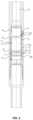
- FIG. 1shows a section view of a barrier plug having a split fingers locking device in accordance with the disclosure in a closed and locked state.
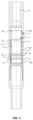
- FIG. 2shows a section view of the barrier plug of FIG. 1 in a closed but unlocked state.
- FIG. 3shows a section view of the barrier plug of FIG. 1 in an open state.
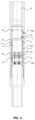
- FIG. 4shows a section view of the barrier plug of FIG. 1 after the frangible barrier element has been shattered, allowing fluid flow through the barrier plug.
- FIG. 5shows a detailed view of a split finger locking device in accordance with the disclosure.
- FIG. 6shows a section view of an embodiment in accordance with the disclosure in a closed and locked state.
- FIG. 7shows a section view of an embodiment in accordance with the disclosure in an opened state.
- FIG. 1illustrates a barrier plug assembly 100 in accordance with an embodiment.
- Barrier plug assembly 100can be arranged inside a housing 10 in a tubing 2 .
- the barrier plug assembly 100can comprise at least one barrier element 1 that may be stacked onto a moveable carrier ring 3 .
- barrier element 1can comprise glass.
- barrier element 1can comprise other frangible materials, such as ceramic, hard polymer, or other material that can break (e.g., fracture or shatter) when a concentrated force is applied.
- the moveable carrier ring 3can be locked in place by means of a retaining device 101 and a locking sleeve 5 .
- the locking sleeve 5can comprise a first cavity 9 .
- the retaining device 101may be arranged inside a second cavity 11 located on the housing 10 .
- the barrier plug assembly 100can further comprise a fluid chamber 6 and a valve 7 configured for allowing or preventing pressure communication in between the housing 10 and the fluid chamber 6 .
- the valve 7can be located on the outside of tubing 2 and in fluid communication with fluid in the annulus between the tubing 2 and the wellbore wall, and configured for allowing or preventing pressure communication between the annulus and the fluid chamber 6 .
- the carrier ring 3 and/or locking sleeve 5can be secured to each other or the tubing 2 using a shear rings, balls, spheres, locking dogs, shear pins, and/or c-clips.
- the barrier plug assembly 100can comprise a breaking, crushing, or shattering element 8 configured for crushing the at least one frangible barrier element 1 .
- the crushing element 8can be any element configured to apply a force to the frangible barrier element 1 sufficient to initiate a fracture in the frangible barrier element 1 .
- the crushing element 8can be a device similar in configuration to the carrier ring 3 , but with a slightly different geometry to induce a load in the frangible barrier element to initiate a fracture.
- the crushing element 8can be located in the downhole direction from the frangible barrier element 1 , where the carrier ring is configured to move in a downhole direction when the locking sleeve 5 is released.
- the crushing element 8can be located in a topside direction from the frangible barrier element 1 , when the carrier ring 3 is configured to move in a topside direction when the locking sleeve 5 is released.
- Embodiments of the present inventionalso include embodiments having multiple crushing elements, located in a topside direction, downhole direction, or both, from the frangible barrier element 1 .
- the barrier plug assembly 100can comprise one or more first sealing elements 12 arranged on the outer surface of the barrier plug assembly 100 for sealing an annulus defined between the barrier plug assembly 100 and the tubing 2 .
- the barrier plug assembly 100can comprise one or more second sealing elements 15 that can define the fluid chamber 6 .
- the one or more second sealing elements 15can be configured to prevent pressure/fluid leakage between the fluid chamber 6 and the rest of the barrier plug assembly 100 .
- FIG. 1shows that the barrier plug assembly 100 that is subject to a pressure region P 1 13 at the top the barrier plug assembly 100 and a pressure region P 2 14 below the barrier plug assembly 100 .
- Pressure region P 1 13applied from an uphole side of the barrier plug assembly 100
- the pressure region P 2 14applied from a downhole side of the barrier plug assembly 100 can be referred to as “formation side pressure.”
- the barrier plug assembly 100can be pre-installed in the tubing 2 before the tubing 2 in lowered in a subsurface wellbore (not shown) or may be installed in the tubing 2 after the tubing 2 is installed in the subsurface wellbore.
- the subsurface wellboreis sealed after the barrier plug assembly 100 is installed in the tubing 2 .
- Theis no fluid communication in the wellbore between the region P 1 13 above the barrier plug assembly 100 and the region P 2 14 below the barrier plug assembly 100 .
- the operatormust break the at least one frangible barrier element 1 of the barrier plug assembly 100 .
- the topside pressure region P 1 13 in the tubing 2may be increased to a value higher than a predetermined opening pressure of the valve 7 .
- the valve 7may be a burst disc, acoustic or magnetic operated valve systems, or similar. After the predetermined opening pressure of the valve 7 is exceeded, or the conditions for opening valve 7 are met, the valve 7 opens to allow fluid/pressure communication from region P 1 13 into the fluid chamber 6 . Pressure in the fluid chamber 6 increases and causes the locking sleeve 5 to move.
- the locking sleeve 5may be a piston arranged inside the fluid chamber 6 and may be configured to move as a result of pressure change in the fluid chamber 6 , either in an uphole direction, or a downhole direction.
- the fluid chamber 6may be an empty chamber or may be filled with a low pressure fluid. In some embodiments, the locking sleeve 5 can be moved or unlocked using a mechanical wireline connection attached to the locking sleeve 5 .
- the locking sleeve 5can comprise a first recess or a first cavity 9 .
- first cavity 9can have a volume equal to or larger than the second recess or second cavity 11 of the tubular housing 10 .
- the locking sleeve 5does not have a first recess or first cavity 9 , such as, for example, in embodiments where the locking sleeve 5 moves in an uphole direction in response to a pressure change in fluid chamber 6 . In such embodiments, the movement of the locking sleeve 5 in an uphole direction can allow the retaining device 101 to disengage from the second cavity 11 when the locking sleeve 5 moves past the second cavity 11 .
- the pressure region P 1 13can be increased until the first cavity 9 of the locking sleeve 5 aligns with the second cavity 11 of the tubular housing 10 .
- the retaining device 101is released from the second cavity 11 and into the first cavity 9 of the locking sleeve 5 .
- the frangible barrier element 1can move in a downhole direction toward a crushing element 8 located downhole from the frangible barrier element 1 .
- the frangible barrier element 1can move in a topside direction towards a crushing element 8 located in a topside direction from the frangible barrier element 1 .
- the movement of the carrier ring 3 towards the crushing element 8can be caused by the release of the retaining device 101 and the pressure difference between the topside pressure region P 1 13 and the formation side pressure region P 2 14 .
- the topside pressure region P 1 13should be increased higher than the formation side pressure region P 2 14 to allow the movement of the carrier ring 3 towards the crushing element 8 .
- the crushing element 8can be studs, spikes, knives or surfaces that are capable of penetrating through the at least one frangible barrier element or causing the frangible barrier element 1 to shatter into small pieces.
- FIG. 4depicts a barrier plug assembly 100 after the frangible barrier element 1 has been shattered, depicting a barrier plug assembly 100 that allows fluid to flow through the carrier ring 3 .
- the barrier plug assembly 100can comprise more than more one retaining device 101 and the locking sleeve 5 and the tubular housing 10 may comprise more than one recess that fit more than one retaining device.
- the retaining device 101can be one or more split fingers attached to, or cut into to carrier ring 3 .
- FIG. 1depicts an embodiment where retaining device 101 is a “finger” connected to carrier ring 3 .
- the finger 101has an upper portion 103 that is shaped such that, when the barrier plug assembly 100 is in a closed and locked position, a part of the upper portion 103 fits in second cavity 11 , securing the carrier ring 3 in place (see FIG. 1 .
- FIG. 2when the first cavity 9 of the locking ring 5 is moved to align with the second cavity 11 , the finger 101 can flex around its connection to carrier ring 5 , and move into the first cavity 9 , unlocking carrier ring 3 .
- FIG. 3once the finger is disposed in first cavity 9 of locking ring 5 , the carrier ring 3 is free to slide in a downhole direction, moving the frangible barrier element 1 to crushing element 8 .
- the retaining devicecan be a ball 4 or a similar object.
- FIG. 6 and FIG. 7depict another embodiment of a barrier plug assembly 100 using a ball 4 as a retaining device. The details not shown of the embodiment depicted in FIG. 7 are substantially the same as those shown in FIGS. 1 - 4 .
- the ball 4In the locked position in FIG. 6 , the ball 4 is disposed in second cavity 11 , securing the carrier ring 3 in place.
- the locking sleeve 5is moved to align first cavity 9 with second cavity 11 , the ball moves into first cavity 9 , unlocking the carrier ring 3 .
- the ball 4can be sheared apart to unlock the carrier ring due to a shear force applied by locking sleeve 5 .
- the carrier ring 3is free to move in a downhole direction.
- the carrier ring 3moves the frangible barrier element 1 in a downhole direction until it contacts crushing element 8 , shattering the frangible barrier element 1 , and allowing fluid to pass through the barrier plug assembly 100 .
- the locking sleeve 5 , the retaining device 101 , 4 and carrier ring 3can all located above the at least one frangible barrier element 1 . Having a releasable sleeve that is arranged below the barrier element 1 means that a passage that extends between the topside of the barrier plug assembly 100 (surface side) and the bottom side of the barrier plug assembly 100 (formation side) is needed.
Landscapes
- Life Sciences & Earth Sciences (AREA)
- Engineering & Computer Science (AREA)
- Geology (AREA)
- Mining & Mineral Resources (AREA)
- Physics & Mathematics (AREA)
- Environmental & Geological Engineering (AREA)
- Fluid Mechanics (AREA)
- General Life Sciences & Earth Sciences (AREA)
- Geochemistry & Mineralogy (AREA)
- Safety Valves (AREA)
- Pressure Vessels And Lids Thereof (AREA)
Abstract
Description
Claims (20)
Priority Applications (1)
| Application Number | Priority Date | Filing Date | Title |
|---|---|---|---|
| US17/504,294US11713649B2 (en) | 2020-02-20 | 2021-10-18 | Plugging device |
Applications Claiming Priority (2)
| Application Number | Priority Date | Filing Date | Title |
|---|---|---|---|
| US16/796,769US11149522B2 (en) | 2020-02-20 | 2020-02-20 | Plugging device |
| US17/504,294US11713649B2 (en) | 2020-02-20 | 2021-10-18 | Plugging device |
Related Parent Applications (1)
| Application Number | Title | Priority Date | Filing Date |
|---|---|---|---|
| US16/796,769ContinuationUS11149522B2 (en) | 2020-02-20 | 2020-02-20 | Plugging device |
Publications (2)
| Publication Number | Publication Date |
|---|---|
| US20220034194A1 US20220034194A1 (en) | 2022-02-03 |
| US11713649B2true US11713649B2 (en) | 2023-08-01 |
Family
ID=77367194
Family Applications (2)
| Application Number | Title | Priority Date | Filing Date |
|---|---|---|---|
| US16/796,769ActiveUS11149522B2 (en) | 2020-02-20 | 2020-02-20 | Plugging device |
| US17/504,294ActiveUS11713649B2 (en) | 2020-02-20 | 2021-10-18 | Plugging device |
Family Applications Before (1)
| Application Number | Title | Priority Date | Filing Date |
|---|---|---|---|
| US16/796,769ActiveUS11149522B2 (en) | 2020-02-20 | 2020-02-20 | Plugging device |
Country Status (2)
| Country | Link |
|---|---|
| US (2) | US11149522B2 (en) |
| CA (1) | CA3108164C (en) |
Cited By (1)
| Publication number | Priority date | Publication date | Assignee | Title |
|---|---|---|---|---|
| WO2025163137A1 (en)* | 2024-02-02 | 2025-08-07 | Interwell Norway As | Well tool device and shatter valve device with actuation system |
Families Citing this family (13)
| Publication number | Priority date | Publication date | Assignee | Title |
|---|---|---|---|---|
| US11639641B2 (en)* | 2019-12-17 | 2023-05-02 | Klx Energy Services, Llc | Degradable in-line buoyant system for running casing in a wellbore |
| US11149522B2 (en)* | 2020-02-20 | 2021-10-19 | Nine Downhole Technologies, Llc | Plugging device |
| US12091936B2 (en)* | 2020-03-30 | 2024-09-17 | Ncs Multistage Inc. | Rupture disc assembly |
| US20220082178A1 (en)* | 2020-09-11 | 2022-03-17 | Patriot Research Center, LLC (DBA Atlas Pressure Control) | Sensing gate valve position |
| US11441382B1 (en)* | 2021-09-21 | 2022-09-13 | Tco As | Plug assembly |
| US11851968B2 (en)* | 2021-09-21 | 2023-12-26 | Tco As | Plug assembly |
| US11332999B1 (en)* | 2021-09-21 | 2022-05-17 | Tco As | Plug assembly |
| NO347391B1 (en)* | 2021-12-20 | 2023-10-09 | Tco As | Breaking Object for a Frangible Plug |
| CA3153162A1 (en) | 2022-03-18 | 2023-08-11 | Torsch Inc. | Barrier member |
| US11808109B1 (en)* | 2022-12-08 | 2023-11-07 | Baker Hughes Oilfield Operations Llc | Frangible disk configuration, method and system |
| US12078027B2 (en)* | 2023-01-26 | 2024-09-03 | Baker Hughes Oilfield Operations Llc | Frangible disk arrangement, method, and system |
| US11988067B1 (en)* | 2023-01-27 | 2024-05-21 | Baker Hughes Oilfield Operations Llc | Frangible disk sub, method and system |
| US12134945B2 (en)* | 2023-02-21 | 2024-11-05 | Baker Hughes Oilfield Operations Llc | Frangible disk sub, method and system |
Citations (52)
| Publication number | Priority date | Publication date | Assignee | Title |
|---|---|---|---|---|
| US1884165A (en) | 1929-09-26 | 1932-10-25 | Herbert C Otis | Temporary seal for well tubing |
| US2565731A (en) | 1946-04-13 | 1951-08-28 | Edgar C Johnston | Disk perforator for pipes in wells |
| US2756828A (en) | 1954-12-14 | 1956-07-31 | Exxon Research Engineering Co | Completing oil wells |
| US3599713A (en) | 1969-09-08 | 1971-08-17 | Fishing Tools Inc | Method and apparatus for controlling the filling of drill pipe or the like with mud during lowering thereof |
| US3831680A (en) | 1972-02-09 | 1974-08-27 | Halliburton Co | Pressure responsive auxiliary disc valve and the like for well cleaning, testing and other operations |
| US4512491A (en) | 1984-01-16 | 1985-04-23 | Fike Metal Products Corporation | Dual range rupture disc assembly |
| US4553559A (en) | 1983-04-29 | 1985-11-19 | Bs&B Safety Systems, Inc. | Rupturable pressure relief assembly |
| US4658902A (en) | 1985-07-08 | 1987-04-21 | Halliburton Company | Surging fluids downhole in an earth borehole |
| US4664184A (en) | 1986-03-31 | 1987-05-12 | Halliburton Company | Balanced isolation tool enabling clean fluid in tubing perforated operations |
| US4691775A (en) | 1986-03-25 | 1987-09-08 | Dresser Industries, Inc. | Isolation valve with frangible flapper element |
| US4813481A (en) | 1987-08-27 | 1989-03-21 | Otis Engineering Corporation | Expendable flapper valve |
| WO1991012451A1 (en) | 1990-02-12 | 1991-08-22 | Chicago Bridge & Iron Technical Services Company | Full flow mechanically activated rupture valve |
| US5050630A (en) | 1990-12-03 | 1991-09-24 | Bs&B Safety Systems, Inc. | Self-positioning rupture disk assembly |
| US5117915A (en) | 1989-08-31 | 1992-06-02 | Union Oil Company Of California | Well casing flotation device and method |
| US5188182A (en) | 1990-07-13 | 1993-02-23 | Otis Engineering Corporation | System containing expendible isolation valve with frangible sealing member, seat arrangement and method for use |
| US5479986A (en) | 1994-05-02 | 1996-01-02 | Halliburton Company | Temporary plug system |
| US5511617A (en) | 1994-08-04 | 1996-04-30 | Snider; Philip M. | Apparatus and method for temporarily plugging a tubular |
| US5829526A (en) | 1996-11-12 | 1998-11-03 | Halliburton Energy Services, Inc. | Method and apparatus for placing and cementing casing in horizontal wells |
| US5924696A (en) | 1997-02-03 | 1999-07-20 | Frazier; Lynn | Frangible pressure seal |
| US5996696A (en) | 1997-06-27 | 1999-12-07 | Fike Corporation | Method and apparatus for testing the integrity of oil delivery tubing within an oil well casing |
| US6334488B1 (en) | 2000-01-11 | 2002-01-01 | Weatherford/Lamb, Inc. | Tubing plug |
| US6397950B1 (en) | 1997-11-21 | 2002-06-04 | Halliburton Energy Services, Inc. | Apparatus and method for removing a frangible rupture disc or other frangible device from a wellbore casing |
| US6472068B1 (en) | 2000-10-26 | 2002-10-29 | Sandia Corporation | Glass rupture disk |
| WO2003052239A1 (en) | 2001-12-17 | 2003-06-26 | Fike Corporation | Hinged rupture disc with circular score line |
| CA2469251A1 (en) | 2002-01-17 | 2003-07-24 | Marioff Corporation Oy | Valve element |
| US20030168214A1 (en) | 2000-04-07 | 2003-09-11 | Odd Sollesnes | Method and device for testing a well |
| US6634430B2 (en) | 2001-12-20 | 2003-10-21 | Exxonmobil Upstream Research Company | Method for installation of evacuated tubular conduits |
| US6672389B1 (en) | 2002-07-31 | 2004-01-06 | Fike Corporation | Bulged single-hinged scored rupture having a non-circular varying depth score line |
| US7117946B2 (en) | 2001-08-03 | 2006-10-10 | Wolfgang Herr | In-situ evaporation |
| US20070012438A1 (en) | 2003-02-14 | 2007-01-18 | Tc Plug Technology As | Arrangement of test plug |
| US7287596B2 (en) | 2004-12-09 | 2007-10-30 | Frazier W Lynn | Method and apparatus for stimulating hydrocarbon wells |
| US7455116B2 (en) | 2005-10-31 | 2008-11-25 | Weatherford/Lamb, Inc. | Injection valve and method |
| US20090020290A1 (en) | 2007-07-16 | 2009-01-22 | Bj Services Company | Frangible flapper valve with hydraulic impact sleeve |
| US20090056955A1 (en) | 2005-10-06 | 2009-03-05 | Resco Corporation | Burst Plug for a Downhole Fluid Passage |
| US7513311B2 (en) | 2006-04-28 | 2009-04-07 | Weatherford/Lamb, Inc. | Temporary well zone isolation |
| WO2009116871A1 (en) | 2008-03-07 | 2009-09-24 | Tco As | Device of a plug for well testing |
| US7661480B2 (en) | 2008-04-02 | 2010-02-16 | Saudi Arabian Oil Company | Method for hydraulic rupturing of downhole glass disc |
| US7673689B2 (en) | 2006-06-12 | 2010-03-09 | Weatherford/Lamb, Inc. | Dual flapper barrier valve |
| US7708066B2 (en) | 2007-12-21 | 2010-05-04 | Frazier W Lynn | Full bore valve for downhole use |
| US7789162B2 (en) | 2005-03-22 | 2010-09-07 | Exxonmobil Upstream Research Company | Method for running tubulars in wellbores |
| CA2670218A1 (en) | 2009-06-22 | 2010-12-22 | Trican Well Service Ltd. | Method for providing stimulation treatments using burst disks |
| US7950409B2 (en) | 2007-01-30 | 2011-05-31 | Fike Corporation | Rupture disc assembly that withstands much higher back pressures than actuation pressure |
| US7963342B2 (en) | 2006-08-31 | 2011-06-21 | Marathon Oil Company | Downhole isolation valve and methods for use |
| US20140008085A1 (en)* | 2011-02-14 | 2014-01-09 | Wtw Solutions As | Well Barrier |
| US8813848B2 (en) | 2010-05-19 | 2014-08-26 | W. Lynn Frazier | Isolation tool actuated by gas generation |
| US8820437B2 (en) | 2010-04-16 | 2014-09-02 | Smith International, Inc. | Cementing whipstock apparatus and methods |
| US9194209B2 (en) | 2007-12-03 | 2015-11-24 | W. Lynn Frazier | Hydraulicaly fracturable downhole valve assembly and method for using same |
| US20160060998A1 (en)* | 2013-03-25 | 2016-03-03 | Vosstech As | Plug apparatus |
| US20170022783A1 (en)* | 2015-07-24 | 2017-01-26 | Magnum Oil Tools International, Ltd. | Interventionless frangible disk isolation tool |
| US9624750B2 (en) | 2009-04-17 | 2017-04-18 | Exxonmobil Upstream Research Company | Systems and methods of diverting fluids in a wellbore using destructible plugs |
| US20180245421A1 (en) | 2015-08-27 | 2018-08-30 | Tco As | Holding and crushing device for barrier plug |
| US11149522B2 (en)* | 2020-02-20 | 2021-10-19 | Nine Downhole Technologies, Llc | Plugging device |
- 2020
- 2020-02-20USUS16/796,769patent/US11149522B2/enactiveActive
- 2021
- 2021-02-04CACA3108164Apatent/CA3108164C/enactiveActive
- 2021-10-18USUS17/504,294patent/US11713649B2/enactiveActive
Patent Citations (56)
| Publication number | Priority date | Publication date | Assignee | Title |
|---|---|---|---|---|
| US1884165A (en) | 1929-09-26 | 1932-10-25 | Herbert C Otis | Temporary seal for well tubing |
| US2565731A (en) | 1946-04-13 | 1951-08-28 | Edgar C Johnston | Disk perforator for pipes in wells |
| US2756828A (en) | 1954-12-14 | 1956-07-31 | Exxon Research Engineering Co | Completing oil wells |
| US3599713A (en) | 1969-09-08 | 1971-08-17 | Fishing Tools Inc | Method and apparatus for controlling the filling of drill pipe or the like with mud during lowering thereof |
| US3831680A (en) | 1972-02-09 | 1974-08-27 | Halliburton Co | Pressure responsive auxiliary disc valve and the like for well cleaning, testing and other operations |
| US4553559A (en) | 1983-04-29 | 1985-11-19 | Bs&B Safety Systems, Inc. | Rupturable pressure relief assembly |
| US4512491A (en) | 1984-01-16 | 1985-04-23 | Fike Metal Products Corporation | Dual range rupture disc assembly |
| US4658902A (en) | 1985-07-08 | 1987-04-21 | Halliburton Company | Surging fluids downhole in an earth borehole |
| US4691775A (en) | 1986-03-25 | 1987-09-08 | Dresser Industries, Inc. | Isolation valve with frangible flapper element |
| US4664184A (en) | 1986-03-31 | 1987-05-12 | Halliburton Company | Balanced isolation tool enabling clean fluid in tubing perforated operations |
| US4813481A (en) | 1987-08-27 | 1989-03-21 | Otis Engineering Corporation | Expendable flapper valve |
| US5117915A (en) | 1989-08-31 | 1992-06-02 | Union Oil Company Of California | Well casing flotation device and method |
| WO1991012451A1 (en) | 1990-02-12 | 1991-08-22 | Chicago Bridge & Iron Technical Services Company | Full flow mechanically activated rupture valve |
| US5188182A (en) | 1990-07-13 | 1993-02-23 | Otis Engineering Corporation | System containing expendible isolation valve with frangible sealing member, seat arrangement and method for use |
| US5050630A (en) | 1990-12-03 | 1991-09-24 | Bs&B Safety Systems, Inc. | Self-positioning rupture disk assembly |
| US5479986A (en) | 1994-05-02 | 1996-01-02 | Halliburton Company | Temporary plug system |
| US5685372A (en) | 1994-05-02 | 1997-11-11 | Halliburton Energy Services, Inc. | Temporary plug system |
| US5511617A (en) | 1994-08-04 | 1996-04-30 | Snider; Philip M. | Apparatus and method for temporarily plugging a tubular |
| US5829526A (en) | 1996-11-12 | 1998-11-03 | Halliburton Energy Services, Inc. | Method and apparatus for placing and cementing casing in horizontal wells |
| US5924696A (en) | 1997-02-03 | 1999-07-20 | Frazier; Lynn | Frangible pressure seal |
| US5996696A (en) | 1997-06-27 | 1999-12-07 | Fike Corporation | Method and apparatus for testing the integrity of oil delivery tubing within an oil well casing |
| US6397950B1 (en) | 1997-11-21 | 2002-06-04 | Halliburton Energy Services, Inc. | Apparatus and method for removing a frangible rupture disc or other frangible device from a wellbore casing |
| US6334488B1 (en) | 2000-01-11 | 2002-01-01 | Weatherford/Lamb, Inc. | Tubing plug |
| US20030168214A1 (en) | 2000-04-07 | 2003-09-11 | Odd Sollesnes | Method and device for testing a well |
| US6472068B1 (en) | 2000-10-26 | 2002-10-29 | Sandia Corporation | Glass rupture disk |
| US6561275B2 (en) | 2000-10-26 | 2003-05-13 | Sandia Corporation | Apparatus for controlling fluid flow in a conduit wall |
| US7117946B2 (en) | 2001-08-03 | 2006-10-10 | Wolfgang Herr | In-situ evaporation |
| WO2003052239A1 (en) | 2001-12-17 | 2003-06-26 | Fike Corporation | Hinged rupture disc with circular score line |
| US6634430B2 (en) | 2001-12-20 | 2003-10-21 | Exxonmobil Upstream Research Company | Method for installation of evacuated tubular conduits |
| CA2469251A1 (en) | 2002-01-17 | 2003-07-24 | Marioff Corporation Oy | Valve element |
| US6672389B1 (en) | 2002-07-31 | 2004-01-06 | Fike Corporation | Bulged single-hinged scored rupture having a non-circular varying depth score line |
| US7624796B2 (en) | 2003-02-14 | 2009-12-01 | Tc Plug Technology As | Arrangement of test plug |
| US20070012438A1 (en) | 2003-02-14 | 2007-01-18 | Tc Plug Technology As | Arrangement of test plug |
| US7287596B2 (en) | 2004-12-09 | 2007-10-30 | Frazier W Lynn | Method and apparatus for stimulating hydrocarbon wells |
| US7789162B2 (en) | 2005-03-22 | 2010-09-07 | Exxonmobil Upstream Research Company | Method for running tubulars in wellbores |
| US20090056955A1 (en) | 2005-10-06 | 2009-03-05 | Resco Corporation | Burst Plug for a Downhole Fluid Passage |
| US7455116B2 (en) | 2005-10-31 | 2008-11-25 | Weatherford/Lamb, Inc. | Injection valve and method |
| US7513311B2 (en) | 2006-04-28 | 2009-04-07 | Weatherford/Lamb, Inc. | Temporary well zone isolation |
| US7963340B2 (en) | 2006-04-28 | 2011-06-21 | Weatherford/Lamb, Inc. | Method for disintegrating a barrier in a well isolation device |
| US7673689B2 (en) | 2006-06-12 | 2010-03-09 | Weatherford/Lamb, Inc. | Dual flapper barrier valve |
| US7963342B2 (en) | 2006-08-31 | 2011-06-21 | Marathon Oil Company | Downhole isolation valve and methods for use |
| US7950409B2 (en) | 2007-01-30 | 2011-05-31 | Fike Corporation | Rupture disc assembly that withstands much higher back pressures than actuation pressure |
| US20090020290A1 (en) | 2007-07-16 | 2009-01-22 | Bj Services Company | Frangible flapper valve with hydraulic impact sleeve |
| US9194209B2 (en) | 2007-12-03 | 2015-11-24 | W. Lynn Frazier | Hydraulicaly fracturable downhole valve assembly and method for using same |
| US7708066B2 (en) | 2007-12-21 | 2010-05-04 | Frazier W Lynn | Full bore valve for downhole use |
| WO2009116871A1 (en) | 2008-03-07 | 2009-09-24 | Tco As | Device of a plug for well testing |
| US7661480B2 (en) | 2008-04-02 | 2010-02-16 | Saudi Arabian Oil Company | Method for hydraulic rupturing of downhole glass disc |
| US9624750B2 (en) | 2009-04-17 | 2017-04-18 | Exxonmobil Upstream Research Company | Systems and methods of diverting fluids in a wellbore using destructible plugs |
| CA2670218A1 (en) | 2009-06-22 | 2010-12-22 | Trican Well Service Ltd. | Method for providing stimulation treatments using burst disks |
| US8820437B2 (en) | 2010-04-16 | 2014-09-02 | Smith International, Inc. | Cementing whipstock apparatus and methods |
| US8813848B2 (en) | 2010-05-19 | 2014-08-26 | W. Lynn Frazier | Isolation tool actuated by gas generation |
| US20140008085A1 (en)* | 2011-02-14 | 2014-01-09 | Wtw Solutions As | Well Barrier |
| US20160060998A1 (en)* | 2013-03-25 | 2016-03-03 | Vosstech As | Plug apparatus |
| US20170022783A1 (en)* | 2015-07-24 | 2017-01-26 | Magnum Oil Tools International, Ltd. | Interventionless frangible disk isolation tool |
| US20180245421A1 (en) | 2015-08-27 | 2018-08-30 | Tco As | Holding and crushing device for barrier plug |
| US11149522B2 (en)* | 2020-02-20 | 2021-10-19 | Nine Downhole Technologies, Llc | Plugging device |
Non-Patent Citations (7)
| Title |
|---|
| Farrar, Chilien M., U.S. Pat. No. 244,042 entitled "Check for Oil Well Tubes," dated Jul. 12, 1881. |
| Frank Allen et al., Extended-Reach Drilling: Breaking the 10-km Barrier (BP Exploration Operation Co. Ltd. 1997) at 46-47. |
| Oil and Gas Online, Single MagnumDisk™ (Jun. 21, 2011). |
| Owen Oil Tools, Magnum Ported Underbalance Sub (Core Lab Sep. 2012), at 1-2. |
| Owen Oil Tools, Surge Tool, Underbalance Sub (Core Lab Jun. 2002), at 1-3. |
| Rogers et al., Buoyancy Technology Used Effectively in Casing Running Operations to Extend Lateral Stepout, SPE/IADC 148541 (Oct. 24, 2011), at 2-3, 11; Fig 13. |
| Shaker et al., Implementation of New Technologies for Oil and Gas Industry, SPE 88738 (Oct. 2004), at 1, 3, 5-6. |
Cited By (1)
| Publication number | Priority date | Publication date | Assignee | Title |
|---|---|---|---|---|
| WO2025163137A1 (en)* | 2024-02-02 | 2025-08-07 | Interwell Norway As | Well tool device and shatter valve device with actuation system |
Also Published As
| Publication number | Publication date |
|---|---|
| US11149522B2 (en) | 2021-10-19 |
| CA3108164A1 (en) | 2021-08-20 |
| US20210262316A1 (en) | 2021-08-26 |
| US20220034194A1 (en) | 2022-02-03 |
| CA3108164C (en) | 2024-06-18 |
Similar Documents
| Publication | Publication Date | Title |
|---|---|---|
| US11713649B2 (en) | Plugging device | |
| US6079496A (en) | Reduced-shock landing collar | |
| US7673689B2 (en) | Dual flapper barrier valve | |
| US6484804B2 (en) | Pumpdown valve plug assembly for liner cementing system | |
| US7114574B2 (en) | By-pass valve mechanism and method of use hereof | |
| US11293262B2 (en) | Well tool device for opening and closing a fluid bore in a well | |
| US4432417A (en) | Control pressure actuated downhole hanger apparatus | |
| US4842062A (en) | Hydraulic lock alleviation device, well cementing stage tool, and related methods | |
| US7905292B2 (en) | Pressure equalization device for downhole tools | |
| US11499394B2 (en) | Well tool device with a breakable ball seat | |
| US20020185276A1 (en) | Apparatus and method for inserting and retrieving a tool string through well surface equipment | |
| US20080210431A1 (en) | Flapper latch | |
| US10605047B2 (en) | Multi-stage valve actuator | |
| AU2003234673A1 (en) | Method and apparatus to reduce downhole surge pressure using hydrostatic valve | |
| US10151169B2 (en) | Dual barrier pump-out plug | |
| US4423782A (en) | Annulus safety apparatus | |
| US20200080397A1 (en) | Valve assembly | |
| US4339001A (en) | Safety valve | |
| US20220136360A1 (en) | Wellbore plug | |
| US8443897B2 (en) | Subsea safety system having a protective frangible liner and method of operating same | |
| US20140069654A1 (en) | Downhole Tool Incorporating Flapper Assembly | |
| GB2530168A (en) | Interventionless method of setting a casing to casing annular packer | |
| US7255174B2 (en) | Cement control ring | |
| EP4256171B1 (en) | Dual ball seat system |
Legal Events
| Date | Code | Title | Description |
|---|---|---|---|
| FEPP | Fee payment procedure | Free format text:ENTITY STATUS SET TO UNDISCOUNTED (ORIGINAL EVENT CODE: BIG.); ENTITY STATUS OF PATENT OWNER: LARGE ENTITY | |
| STPP | Information on status: patent application and granting procedure in general | Free format text:DOCKETED NEW CASE - READY FOR EXAMINATION | |
| STPP | Information on status: patent application and granting procedure in general | Free format text:NON FINAL ACTION MAILED | |
| STPP | Information on status: patent application and granting procedure in general | Free format text:RESPONSE TO NON-FINAL OFFICE ACTION ENTERED AND FORWARDED TO EXAMINER | |
| AS | Assignment | Owner name:NINE DOWNHOLE TECHNOLOGIES, LLC, TEXAS Free format text:ASSIGNMENT OF ASSIGNORS INTEREST;ASSIGNORS:BRANDSDAL, VIGGO;AASHEIM, GEIR VALESTRAND;REEL/FRAME:062395/0916 Effective date:20230113 | |
| AS | Assignment | Owner name:U.S. BANK TRUST COMPANY, NATIONAL ASSOCIATION, AS COLLATERAL AGENT, TENNESSEE Free format text:PATENT SECURITY AGREEMENT (NOTES);ASSIGNORS:NINE ENERGY SERVICE, INC.;NINE DOWNHOLE TECHNOLOGIES, LLC;MAGNUM OIL TOOLS INTERNATIONAL, LTD.;REEL/FRAME:062545/0970 Effective date:20230130 Owner name:JPMORGAN CHASE BANK, N.A., AS ADMINISTRATIVE AGENT, ILLINOIS Free format text:PATENT SECURITY AGREEMENT (ABL);ASSIGNORS:NINE ENERGY SERVICE, INC.;NINE DOWNHOLE TECHNOLOGIES, LLC;MAGNUM OIL TOOLS INTERNATIONAL, LTD.;REEL/FRAME:062546/0076 Effective date:20230130 | |
| STPP | Information on status: patent application and granting procedure in general | Free format text:PUBLICATIONS -- ISSUE FEE PAYMENT VERIFIED | |
| STCF | Information on status: patent grant | Free format text:PATENTED CASE | |
| CC | Certificate of correction | ||
| AS | Assignment | Owner name:WHITE OAK COMMERCIAL FINANCE, LLC, NEW YORK Free format text:SECURITY INTEREST;ASSIGNORS:NINE ENERGY SERVICE, INC.;NINE DOWNHOLE TECHNOLOGIES, LLC;NINE ENERGY CANADA INC.;REEL/FRAME:071147/0203 Effective date:20250501 | |
| AS | Assignment | Owner name:MAGNUM OIL TOOLS INTERNATIONAL LTD., TEXAS Free format text:RELEASE BY SECURED PARTY;ASSIGNOR:JPMORGAN CHASE BANK, N.A.;REEL/FRAME:071155/0559 Effective date:20250501 Owner name:NINE DOWNHOLE TECHNOLOGIES, LLC, TEXAS Free format text:RELEASE BY SECURED PARTY;ASSIGNOR:JPMORGAN CHASE BANK, N.A.;REEL/FRAME:071155/0559 Effective date:20250501 Owner name:NINE ENERGY SERVICE, INC., TEXAS Free format text:RELEASE BY SECURED PARTY;ASSIGNOR:JPMORGAN CHASE BANK, N.A.;REEL/FRAME:071155/0559 Effective date:20250501 |