US11713645B2 - Downhole setting system for use in a wellbore - Google Patents
Downhole setting system for use in a wellboreDownload PDFInfo
- Publication number
- US11713645B2 US11713645B2US17/072,121US202017072121AUS11713645B2US 11713645 B2US11713645 B2US 11713645B2US 202017072121 AUS202017072121 AUS 202017072121AUS 11713645 B2US11713645 B2US 11713645B2
- Authority
- US
- United States
- Prior art keywords
- slip
- tool
- downhole
- downhole tool
- mandrel
- Prior art date
- Legal status (The legal status is an assumption and is not a legal conclusion. Google has not performed a legal analysis and makes no representation as to the accuracy of the status listed.)
- Active, expires
Links
Images


Classifications
- E—FIXED CONSTRUCTIONS
- E21—EARTH OR ROCK DRILLING; MINING
- E21B—EARTH OR ROCK DRILLING; OBTAINING OIL, GAS, WATER, SOLUBLE OR MELTABLE MATERIALS OR A SLURRY OF MINERALS FROM WELLS
- E21B23/00—Apparatus for displacing, setting, locking, releasing or removing tools, packers or the like in boreholes or wells
- E21B23/01—Apparatus for displacing, setting, locking, releasing or removing tools, packers or the like in boreholes or wells for anchoring the tools or the like
- E—FIXED CONSTRUCTIONS
- E21—EARTH OR ROCK DRILLING; MINING
- E21B—EARTH OR ROCK DRILLING; OBTAINING OIL, GAS, WATER, SOLUBLE OR MELTABLE MATERIALS OR A SLURRY OF MINERALS FROM WELLS
- E21B33/00—Sealing or packing boreholes or wells
- E21B33/10—Sealing or packing boreholes or wells in the borehole
- E21B33/12—Packers; Plugs
- E21B33/129—Packers; Plugs with mechanical slips for hooking into the casing
- E21B33/1293—Packers; Plugs with mechanical slips for hooking into the casing with means for anchoring against downward and upward movement
- E—FIXED CONSTRUCTIONS
- E21—EARTH OR ROCK DRILLING; MINING
- E21B—EARTH OR ROCK DRILLING; OBTAINING OIL, GAS, WATER, SOLUBLE OR MELTABLE MATERIALS OR A SLURRY OF MINERALS FROM WELLS
- E21B23/00—Apparatus for displacing, setting, locking, releasing or removing tools, packers or the like in boreholes or wells
- E—FIXED CONSTRUCTIONS
- E21—EARTH OR ROCK DRILLING; MINING
- E21B—EARTH OR ROCK DRILLING; OBTAINING OIL, GAS, WATER, SOLUBLE OR MELTABLE MATERIALS OR A SLURRY OF MINERALS FROM WELLS
- E21B33/00—Sealing or packing boreholes or wells
- E21B33/10—Sealing or packing boreholes or wells in the borehole
- E21B33/12—Packers; Plugs
- E21B33/1208—Packers; Plugs characterised by the construction of the sealing or packing means
- E—FIXED CONSTRUCTIONS
- E21—EARTH OR ROCK DRILLING; MINING
- E21B—EARTH OR ROCK DRILLING; OBTAINING OIL, GAS, WATER, SOLUBLE OR MELTABLE MATERIALS OR A SLURRY OF MINERALS FROM WELLS
- E21B33/00—Sealing or packing boreholes or wells
- E21B33/10—Sealing or packing boreholes or wells in the borehole
- E21B33/12—Packers; Plugs
- E21B33/129—Packers; Plugs with mechanical slips for hooking into the casing
- E21B33/1291—Packers; Plugs with mechanical slips for hooking into the casing anchor set by wedge or cam in combination with frictional effect, using so-called drag-blocks
- E—FIXED CONSTRUCTIONS
- E21—EARTH OR ROCK DRILLING; MINING
- E21B—EARTH OR ROCK DRILLING; OBTAINING OIL, GAS, WATER, SOLUBLE OR MELTABLE MATERIALS OR A SLURRY OF MINERALS FROM WELLS
- E21B2200/00—Special features related to earth drilling for obtaining oil, gas or water
- E21B2200/08—Down-hole devices using materials which decompose under well-bore conditions
Definitions
- This disclosuregenerally relates to downhole tools and related systems and methods used in oil and gas wellbores. More specifically, the disclosure relates to a downhole system and tool that may be run into a wellbore and useable for wellbore isolation, and methods pertaining to the same.
- the downhole toolmay be a plug made of drillable materials.
- one or more componentsmay be made of a dissolvable material, any of which may be composite- or metal-based.
- An oil or gas wellincludes a wellbore extending into a subterranean formation at some depth below a surface (e.g., Earth's surface), and is usually lined with a tubular, such as casing, to add strength to the well.
- a surfacee.g., Earth's surface
- a tubularsuch as casing
- Many commercially viable hydrocarbon sourcesare found in “tight” reservoirs, which means the target hydrocarbon product may not be easily extracted.
- the surrounding formation (e.g., shale) to these reservoirstypically has low permeability, and it is uneconomical to produce the hydrocarbons (i.e., gas, oil, etc.) in commercial quantities from this formation without the use of drilling accompanied with fracing operations.
- Fracingnow has a significant presence in the industry, and is commonly understood to include the use of some type of plug set in the wellbore below or beyond the respective target zone, followed by pumping or injecting high pressure frac fluid into the zone.
- fracingand any associated or peripheral operation
- a frac plug and accompanying operationmay be such as described or otherwise disclosed in U.S. Pat. No. 8,955,605, incorporated by reference herein in its entirety for all purposes.
- FIG. 1illustrates a conventional plugging system 100 that includes use of a downhole tool 102 used for plugging a section of the wellbore 106 drilled into formation 110 .
- the tool or plug 102may be lowered into the wellbore 106 by way of workstring 112 (e.g., e-line, wireline, coiled tubing, etc.) and/or with setting tool 117 , as applicable.
- the tool 102generally includes a body 103 with a compressible seal member 122 to seal the tool 102 against an inner surface 107 of a surrounding tubular, such as casing 108 .
- the tool 102may include the seal member 122 disposed between one or more slips 109 , 111 that are used to help retain the tool 102 in place.
- the tool 102provides a seal expected to prevent transfer of fluids from one section 113 of the wellbore across or through the tool 102 to another section 115 (or vice versa, etc.), or to the surface.
- Tool 102may also include an interior passage (not shown) that allows fluid communication between section 113 and section 115 when desired by the user. Oftentimes multiple sections are isolated by way of one or more additional plugs (e.g., 102 A).
- the setting tool 117is incorporated into the workstring 112 along with the downhole tool 102 .
- Examples of commercial setting toolsinclude the Baker #10 and #20, and the ‘Owens Go’.
- the plugmay be subjected to high or extreme pressure and temperature conditions, which means the plug must be capable of withstanding these conditions without destruction of the plug or the seal formed by the seal element.
- High temperaturesare generally defined as downhole temperatures above 200° F.
- high pressuresare generally defined as downhole pressures above 7,500 psi, and even in excess of 15,000 psi.
- Extreme wellbore conditionsmay also include high and low pH environments. In these conditions, conventional tools, including those with compressible seal elements, may become ineffective from degradation. For example, the sealing element may melt, solidify, or otherwise lose elasticity, resulting in a loss the ability to form a seal barrier.
- plugsBefore production operations may commence, conventional plugs typically require some kind of removal process, such as milling or drilling. Drilling typically entails drilling through the set plug, but in some instances the plug can be removed from the wellbore essentially intact (i.e., retrieval).
- a common problem with retrievable plugsis the accumulation of debris on the top of the plug, which may make it difficult or impossible to engage and remove the plug. Such debris accumulation may also adversely affect the relative movement of various parts within the plug.
- jarring motions or friction against the well casingmay cause accidental unlatching of the retrieving tool (resulting in the tools slipping further into the wellbore), or re-locking of the plug (due to activation of the plug anchor elements). Problems such as these often make it necessary to drill out a plug that was intended to be retrievable.
- plugsare required to withstand extreme downhole conditions, they are built for durability and toughness, which often makes the drill-through process difficult, time-consuming, and/or require considerable expertise.
- drillable plugsare typically constructed of a metal such as cast iron that may be drilled out with a drill bit at the end of a drill string. Steel may also be used in the structural body of the plug to provide structural strength to set the tool. The more metal parts used in the tool, the longer the drilling operation takes. Because metallic components are harder to drill through, this process may require additional trips into and out of the wellbore to replace worn out drill bits.
- Composite materialssuch as filament wound materials, have enjoyed success in the frac industry because of easy-to-drill tendencies.
- the process of making filament wound materialsis known in the art, and although subject to differences, typically entails a known process. However, even composite plugs require drilling, or often have one or more pieces of metal (sometimes hardened metal).
- plugs in a wellboreare not without other problems, as these tools are subject to known failure modes.
- the slipsWhen the plug is run into position, the slips have a tendency to pre-set before the plug reaches its destination, resulting in damage to the casing and operational delays. Pre-set may result, for example, because of residue or debris (e.g., sand) left from a previous frac.
- conventional plugsare known to provide poor sealing, not only with the casing, but also between the plug's components. For example, when the sealing element is placed under compression, its surfaces do not always seal properly with surrounding components (e.g., cones, etc.).
- Downhole toolsare often activated with a drop ball that is flowed from the surface down to the tool, whereby the pressure of the fluid must be enough to overcome the static pressure and buoyant forces of the wellbore fluid(s) in order for the ball to reach the tool.
- Frac fluidis also highly pressurized in order to not only transport the fluid into and through the wellbore, but also extend into the formation in order to cause fracture. Accordingly, a downhole tool must be able to withstand these additional higher pressures.
- Such a materialessentially self-actuated by changes in its surrounding (e.g., the presence a specific fluid, a change in temperature, and/or a change in pressure, etc.) may potentially replace costly and complicated designs and may be most advantageous in situations where accessibility is limited or even considered to be impossible, which is the case in a downhole (subterranean) environment.
- these materialstend to be exotic, rendering related tools made of such materials undesirable as a result of high cost.
- Embodiments of the disclosurepertain to a downhole tool for use in a wellbore that may include any of the following: a cone mandrel comprising: a distal end; a proximate end; and an outer surface. There may be a carrier ring slidingly engaged with the distal end. The carrier ring may include an outer seal element groove. There may be a seal element disposed in the outer seal element groove. There may be a slip engaged with the proximate end. There may be a lower sleeve coupled with the slip.
- the cone mandrelmay be dual-frustoconical in shape.
- the outer surfacemay include a first angled surface and a second angled surface.
- the first angled surfacemay include a first plane that in cross section bisects a longitudinal axis a first angle range of 5 degrees to 40 degrees.
- the second angled surfacemay be negative to the first angled surface.
- the second angled surfacemay include a second plane that in cross section bisects the longitudinal angle negative to that of the first angle.
- the second anglemay be in a second angle range of 5 degrees to 40 degrees.
- the slipmay include an at least one slip groove that forms a lateral opening in the slip.
- the slip groovemay be defined by a first portion of slip material at a first slip end, a second portion of slip material at a second slip end.
- the slip groovemay have a depth that extends from a slip outer surface to a slip inner surface.
- the slipmay have an at least one pin window adjacent the at least one slip groove.
- the lower sleevemay have a pin groove proximate to the at least one pin window. There may be a pin disposed within either or both of the at least one pin window and the at least one pin window.
- Any component of the downhole toolmay be made of a composite material. Any component of the downhole tool is made of a dissolvable material.
- the dissolvable materialmay be composite- or metal-based.
- the slipmay include an at least one primary fracture.
- the carrier ringmay be configured to elongate by about 10% to 20% with respect to its original shape.
- the carrier ringmay elongate without fracturing.
- the downhole tool(or cone mandrel) may have an inner flowbore.
- the inner flowboremay have an inner diameter in a bore range of about 1 inch to 5 inches.
- the lower sleevemay have a shear tab.
- the seal elementis not engaged or otherwise directly in contact with a cone.
- a longitudinal length of the downhole tool after settingmay be in a set length range of about 5 inches to about 15 inches.
- the cone mandrelmay include a ball seat formed within an inner flowbore.
- a downhole setting systemfor use in a wellbore that may include a workstring; a setting tool assembly coupled to the workstring; and a downhole tool coupled with the setting tool assembly.
- the setting toolmay include a tension mandrel having a first tension mandrel end and a second tension mandrel end.
- the setting tool assemblymay include a setting sleeve.
- the downhole toolmay include: a cone mandrel comprising: a distal end; a proximate end; and an outer surface.
- the downhole toolmay have a carrier ring slidingly engaged with the distal end.
- the carrier ringmay include an outer seal element groove.
- the tension mandrelmay be disposed through the downhole tool. There may be a nose nut is engaged with each of the second tension mandrel end and the lower sleeve.
- the outer surface of the cone mandrelmay be dual frustoconical.
- the first angled surfacemay include a first plane that in cross section bisects a longitudinal axis a first angle range of 5 degrees to 40 degrees.
- the second angled surfacemay include a second plane that in cross section bisects the longitudinal angle negative to that of the first angle.
- the second anglemay be in a second angle range of (negative) 5 degrees to 40 degrees.
- the cone mandrelmay include a ball seat formed within an inner flowbore.
- Any component of the downhole toolmay be made of a polymer-based material. Any component of the downhole tool may be made of a metallic-based material.
- Embodiments of the disclosurepertain to a downhole tool suitable for use in a wellbore.
- the downhole toolmay include a mandrel made of a reactive material, which may be metallic-based.
- the mandrelmay include a distal end; a proximate end; and an outer surface.
- the unset downhole toolmay be about 4 inches to about 20 inches in longitudinal length.
- the downhole tool in its fully set positionmay be less than 15 inches in longitudinal length.
- FIG. 1is a side view of a process diagram of a conventional plugging system
- FIG. 2 Ashows an isometric view of a system having a downhole tool, according to embodiments of the disclosure
- FIG. 2 Bshows an isometric breakout view of a system having a downhole tool, according to embodiments of the disclosure
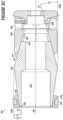
- FIG. 2 Cshows a longitudinal side cross-sectional view of an unset downhole tool according to embodiments of the disclosure
- FIG. 2 Dshows a longitudinal side cross-sectional view of the downhole tool of FIG. 2 C in a set position according to embodiments of the disclosure
- FIG. 2 Eshows a longitudinal side cross-sectional view of the downhole tool of FIG. 2 C in a set position and disconnected from a workstring according to embodiments of the disclosure
- FIG. 3 Ashows an isometric component breakout view of a downhole tool according to embodiments of the disclosure
- FIG. 3 Bshows an isometric assembled view of the downhole tool of FIG. 3 A according to embodiments of the disclosure
- FIG. 3 Cshows a longitudinal side cross-sectional view of the downhole tool of FIG. 3 B according to embodiments of the disclosure
- FIG. 4 Ashows a longitudinal side cross-sectional view of a downhole tool having a flapper according to embodiments of the disclosure.
- FIG. 4 Bshows a longitudinal side cross-sectional view of the downhole tool of FIG. 4 A with the flapper open according to embodiments of the disclosure.
- Connection(s), couplings, or other forms of contact between parts, components, and so forthmay include conventional items, such as lubricant, additional sealing materials, such as a gasket between flanges, PTFE between threads, and the like.
- additional sealing materialssuch as a gasket between flanges, PTFE between threads, and the like.
- the make and manufacture of any particular component, subcomponent, etc.may be as would be apparent to one of skill in the art, such as molding, forming, press extrusion, machining, or additive manufacturing.
- Embodiments of the disclosureprovide for one or more components that may be new, used, and/or retrofitted.
- Fluid communicationmay occur via one or more transfer lines and respective connectors, couplings, valving, and so forth.
- Fluid moverssuch as pumps, may be utilized as would be apparent to one of skill in the art.
- Numerical ranges in this disclosuremay be approximate, and thus may include values outside of the range unless otherwise indicated. Numerical ranges include all values from and including the expressed lower and the upper values, in increments of smaller units. As an example, if a compositional, physical or other property, such as, for example, molecular weight, viscosity, temperature, pressure, distance, melt index, etc., is from 100 to 1,000, it is intended that all individual values, such as 100, 101, 102, etc., and sub ranges, such as 100 to 144, 155 to 170, 197 to 200, etc., are expressly enumerated. It is intended that decimals or fractions thereof be included.
- a compositional, physical or other propertysuch as, for example, molecular weight, viscosity, temperature, pressure, distance, melt index, etc.
- Embodiments hereinmay be described at the macro level, especially from an ornamental or visual appearance.
- a dimension, such as lengthmay be described as having a certain numerical unit, albeit with or without attribution of a particular significant figure.
- the dimension of “2 centimeters”may not be exactly 2 centimeters, and that at the micro-level may deviate.
- reference to a “uniform” dimension, such as thicknessneed not refer to completely, exactly uniform.
- a uniform or equal thickness of “1 millimeter”may have discernable variation at the micro-level within a certain tolerance (e.g., 0.001 millimeter) related to imprecision in measuring and fabrication.
- connectionmay refer to a connection between a respective component (or subcomponent) and another component (or another subcomponent), which can be fixed, movable, direct, indirect, and analogous to engaged, coupled, disposed, etc., and can be by screw, nut/bolt, weld, and so forth. Any use of any form of the terms “connect”, “engage”, “couple”, “attach”, “mount”, etc. or any other term describing an interaction between elements is not meant to limit the interaction to direct interaction between the elements and may also include indirect interaction between the elements described.
- fluidmay refer to a liquid, gas, slurry, multi-phase, etc. and is not limited to any particular type of fluid such as hydrocarbons.
- fluid connectionmay refer to two or more components, systems, etc. being coupled whereby fluid from one may flow or otherwise be transferrable to the other.
- the couplingmay be direct or indirect.
- valves, flow meters, pumps, mixing tanks, holding tanks, tubulars, separation systems, and the likemay be disposed between two or more components that are in fluid communication.
- pipemay refer to any fluid transmission means, and may be tubular in nature.
- compositionor “composition of matter” as used herein may refer to one or more ingredients, components, constituents, etc. that make up a material (or material of construction).
- Compositionmay refer to a flow stream, or the material of construction of a component of a downhole tool, of one or more chemical components.
- chemicalas used herein may analogously mean or be interchangeable to material, chemical material, ingredient, component, chemical component, element, substance, compound, chemical compound, molecule(s), constituent, and so forth and vice versa. Any ‘chemical’ discussed in the present disclosure need not refer to a 100% pure chemical.
- watermay be thought of as H2O, one of skill would appreciate various ions, salts, minerals, impurities, and other substances (including at the ppb level) may be present in ‘water’.
- a chemicalmay include all isomeric forms and vice versa (for example, “hexane”, includes all isomers of hexane individually or collectively).
- pumpmay refer to a mechanical device suitable to use an action such as suction or pressure to raise or move liquids, compress gases, and so forth.
- ‘Pump’can further refer to or include all necessary subcomponents operable together, such as impeller (or vanes, etc.), housing, drive shaft, bearings, etc.
- ‘pump’can further include reference to a driver, such as an engine and drive shaft.
- Types of pumpsinclude gas powered, hydraulic, pneumatic, and electrical.
- frac operationmay refer to fractionation of a downhole well that has already been drilled. ‘Frac operation’ can also be referred to and interchangeable with the terms fractionation, hydrofracturing, hydrofracking, fracking, fracing, frac, and the like. A frac operation can be land or water based.
- mountedmay refer to a connection between a respective component (or subcomponent) and another component (or another subcomponent), which can be fixed, movable, direct, indirect, and analogous to engaged, coupled, disposed, etc., and can be by screw, nut/bolt, weld, and so forth.
- reactive materialmay refer a material with a composition of matter having properties and/or characteristics that result in the material responding to a change over time and/or under certain conditions.
- reactive materialmay encompass degradable, dissolvable, disassociatable, dissociable, and so on.
- degradable materialmay refer to a composition of matter having properties and/or characteristics that, while subject to change over time and/or under certain conditions, lead to a change in the integrity of the material.
- the materialmay initially be hard, rigid, and strong at ambient or surface conditions, but over time (such as within about 12-36 hours) and under certain conditions (such as wellbore conditions), the material softens.
- the term “dissolvable material”may be analogous to degradable material.
- the term as used hereinmay refer to a composition of matter having properties and/or characteristics that, while subject to change over time and/or under certain conditions, lead to a change in the integrity of the material, including to the point of degrading, or partial or complete dissolution.
- the materialmay initially be hard, rigid, and strong at ambient or surface conditions, but over time (such as within about 12-36 hours) and under certain conditions (such as wellbore conditions), the material softens.
- the materialmay initially be hard, rigid, and strong at ambient or surface conditions, but over time (such as within about 12-36 hours) and under certain conditions (such as wellbore conditions), the material dissolves at least partially, and may dissolve completely.
- the materialmay dissolve via one or more mechanisms, such as oxidation, reduction, deterioration, go into solution, or otherwise lose sufficient mass and structural integrity.
- breakable materialmay refer to a composition of matter having properties and/or characteristics that, while subject to change over time and/or under certain conditions, lead to brittleness.
- the materialmay be hard, rigid, and strong at ambient or surface conditions, but over time and under certain conditions, becomes brittle.
- the breakable materialmay experience breakage into multiple pieces, but not necessarily dissolution.
- a material of constructionmay include a composition of matter designed or otherwise having the inherent characteristic to react or change integrity or other physical attribute when exposed to certain wellbore conditions, such as a change in time, temperature, water, heat, pressure, solution, combinations thereof, etc.
- Heatmay be present due to the temperature increase attributed to the natural temperature gradient of the earth, and water may already be present in existing wellbore fluids.
- the change in integritymay occur in a predetermined time period, which may vary from several minutes to several weeks. In aspects, the time period may be about 12 to about 36 hours.
- machinedcan refer to a computer numerical control (CNC) process whereby a robot or machinist runs computer-operated equipment to create machine parts, tools and the like.
- CNCcomputer numerical control
- planeor “planar” as used herein may refer to any surface or shape that is flat, at least in cross-section.
- a frusto-conical surfacemay appear to be planar in 2D cross-section. It should be understood that plane or planar need not refer to exact mathematical precision, but instead be contemplated as visual appearance to the naked eye.
- a plane or planarmay be illustrated in 2D by way of a line.
- parallelmay refer to any surface or shape that may have a reference plane lying in the same direction or vector as that of another. It should be understood that parallel need not refer to exact mathematical precision, but instead be contemplated as visual appearance to the naked eye.
- cone mandrelmay refer to a tubular component having an at least one generally frustoconical surface.
- the cone mandrelmay have an external surface that in cross section has a reference line/plane bisecting a reference axis at an angle.
- the cone mandrelmay be a dual (also “dual faced”, “double faced, and the like) cone, meaning there may be a second external surface having a second reference line/plane bisecting the reference axis (in cross-section) at a second angle.
- the second anglemay be negative to the first angle (e.g., +10 degrees for the first, ⁇ 10 degrees for the second).
- FIGS. 2 A and 2 Bisometric views of a system 200 having a downhole tool 202 illustrative of embodiments disclosed herein, are shown.
- FIG. 2 Bdepicts a wellbore 206 formed in a subterranean formation 210 with a tubular 208 disposed therein.
- the tubular 208may be casing (e.g., casing, hung casing, casing string, etc.) (which may be cemented), and the like.
- a workstring 212(which may include a setting tool [or a part 217 of a setting tool] configured with an adapter 252 ) may be used to position or run the downhole tool 202 into and through the wellbore 206 to a desired location.
- the setting toolmay be like that provided by Baker or Owen.
- the setting tool assembly 217may include or be associated with a setting sleeve 254 .
- the setting sleeve 254may be engaged with the downhole tool (or a component thereof) 202 .
- the setting toolmay include a tension mandrel 216 associated (e.g., coupled) with an adapter 252 .
- the adapter 252may be coupled with the setting tool (or part thereof) 217
- the tension mandrel 216may be coupled with the adapter 252 .
- the couplingmay be a threaded connection (such as via threads on the adapter 252 and corresponding threads of the tension mandrel 216 —not shown here).
- the tension mandrel 216may extend, at least partially, out of the (bottom/downhole/distal end) tool 202 .
- An end or extension 216 a of the tension mandrel 216may be coupled with a nose sleeve or nut 224 .
- the nut 224may have a threaded connection 225 with the end 216 a (and thus corresponding mating threads), although other forms of coupling may be possible.
- one or more set screws 226may be disposed through set screw holes 227 and screwed into or tightened against the end 216 a .
- the nut 224may engage or abut against a shear tab of a lower sleeve 260 .
- the downhole tool 202may be annular in nature, and thus centrally disposed or arranged with respect to a longitudinal axis 258 .
- the tool 202may be configured as a plugging tool, which may be set within the tubular 208 in such a manner that the tool 202 forms a fluid-tight seal against the inner surface 207 of the tubular 208 .
- the sealmay be facilitated by a seal element 222 expanded into a sealing position against the inner surface 207 .
- the seal element 222may be supported by a carrier ring 223 .
- the carrier ring 223may be disposed around a cone mandrel 214 .
- the downhole tool 202may be configured as a bridge plug, whereby flow from one section of the wellbore to another (e.g., above and below the tool 202 ) is controlled.
- the downhole tool 202may be configured as a frac plug, where flow into one section 213 of the wellbore 206 may be blocked and otherwise diverted into the surrounding formation or reservoir 210 .
- the downhole tool 202may also be configured as a ball drop tool.
- a balle.g., 285 , FIG. 2 E
- the seating of the ballmay provide a seal within the tool 202 resulting in a plugged condition, whereby a pressure differential across the tool 202 may result.
- the ball seatmay include a radius or curvature. The radius or curvature may be convex or concave in nature.
- the downhole tool 202may be a ball check plug, whereby the tool 202 is configured with a ball already in place when the tool 202 runs into the wellbore.
- the tool 202may then act as a check valve, and provide one-way flow capability. Fluid may be directed from the wellbore 206 to the formation 210 with any of these configurations.
- the setting mechanism or workstring 212may be detached from the tool 202 by various methods, resulting in the tool 202 left in the surrounding tubular 208 and one or more sections (e.g., 213 ) of the wellbore 206 isolated.
- tensionmay be applied to the setting tool ( 217 ) until a shearable connection between the tool 202 and the workstring 212 is broken.
- the downhole tool 202may have other forms of disconnect.
- the amount of load applied to the setting tool and the shearable connectionmay be in the range of about, for example, 20,000 to 55,000 pounds force.
- the tension mandrel 216may separate or detach from a lower sleeve 260 (directly or indirectly)), resulting in the workstring 212 being able to separate from the tool 202 , which may be at a predetermined moment.
- the loads provided hereinare non-limiting and are merely exemplary.
- the setting forcemay be determined by specifically designing the interacting surfaces of the tool 202 and the respective tool surface angles.
- the tool 202may also be configured with a predetermined failure point (not shown) configured to fail, break, or otherwise induce fracture.
- the lower sleeve 260may be configured with a groove having an association with the shearable connection or tab, the groove being suitable to induce proximate fracture.
- Operation of the downhole tool 202may allow for fast run in of the tool 202 to isolate one or more sections of the wellbore 206 , as well as quick and simple drill-through or dissolution to destroy or remove the tool 202 .
- drill-throughmay be completely unnecessary.
- the downhole tool 202may have one or more components made of a reactive material, such as a metal or metal alloys.
- the downhole tool 202may have one or more components made of a reactive material (e.g., dissolvable, degradable, etc.), which may be composite- or metal-based.
- one or more components of a tool of embodiments disclosed hereinmay be made of reactive materials (e.g., materials suitable for and are known to dissolve, degrade, etc. in downhole environments [including extreme pressure, temperature, fluid properties, etc.] after a brief or limited period of time (predetermined or otherwise) as may be desired).
- a component made of a reactive materialmay begin to react within about 3 to about 48 hours after setting of the downhole tool 202 .
- one or more componentsmay be made of a metallic material, such as an aluminum-based or magnesium-based material.
- the metallic materialmay be reactive, such as dissolvable, which is to say under certain conditions the respective component(s) may begin to dissolve, and thus alleviating the need for drill thru. These conditions may be anticipated and thus predetermined.
- the components of the tool 202may be made of dissolvable aluminum-, magnesium-, or aluminum-magnesium-based (or alloy, complex, etc.) material, such as that provided by Nanjing Highsur Composite Materials Technology Co. LTD or Terves, Inc.
- One or more components of tool 202may be made of non-dissolvable materials (e.g., materials suitable for and are known to withstand downhole environments [including extreme pressure, temperature, fluid properties, etc.] for an extended period of time (predetermined or otherwise) as may be desired).
- non-dissolvable materialse.g., materials suitable for and are known to withstand downhole environments [including extreme pressure, temperature, fluid properties, etc.] for an extended period of time (predetermined or otherwise) as may be desired).
- the downhole tool 202(and other tool embodiments disclosed herein) and/or one or more of its components may be 3D-printed or made with other forms of additive manufacturing.
- FIGS. 2 C- 2 Ea longitudinal side cross-sectional view of a system having an unset downhole tool, a set downhole tool, and a set downhole tool disconnected from a workstring, respectively, according to embodiments of the disclosure, are shown.
- the setting device(s) and components of the downhole tool 202may be coupled with, and axially and/or longitudinally movable, at least partially, with respect to each other.
- the downhole tool 202may include a cone mandrel 214 that extends through the tool 202 (or tool body).
- the cone mandrel 214may be a solid body.
- the cone mandrel 214may include a flowpath or bore 250 formed therein (e.g., an axial bore, inner flowbore, etc.).
- the bore 250may extend partially or for a short distance through the cone mandrel 214 .
- the bore 250may extend through the entire mandrel 214 , with an opening at its proximate end 248 and oppositely at its distal end 246 (near downhole end of the tool 202 ), as illustrated by FIG. 2 E .
- the presence of the bore 250 or other flowpath through the cone mandrel 214may indirectly be dictated by operating conditions. That is, in most instances the tool 202 may be large enough in diameter (e.g., 43 ⁇ 4 inches) that the bore 250 may be correspondingly large enough (e.g., 11 ⁇ 4 inches) so that debris and junk may pass or flow through the bore 250 without plugging concerns.
- the cone mandrel 214may have an inner bore surface 247 , which may be smooth and annular in nature.
- the bore surface 247may be planar.
- the bore surface 247 (in cross-section)may be parallel to a (central) tool axis 258 .
- An outer mandrel surface 230may have one or more surfaces (in cross-section) offset or angled to the tool axis 258 .
- the bore 250(and thus the tool 202 ) may be configured for part of a setting tool assembly 217 to fit therein, such as a tension mandrel 216 .
- the tension mandrel 216which may be contemplated as being part of the setting tool assembly 217 , may be configured for the downhole tool 202 (or components thereof) to be disposed therearound (such as during run-in).
- the downhole tool 202may be coupled with the setting tool assembly 217 (and around the tension mandrel 216 ), but not in a threaded manner.
- the downhole tool 202(by itself, and not including setting tool components) may be completely devoid of threaded connections.
- an adapter 252may include threads 256 thereon. Such threads 256 may correspond to mate with threads of the setting sleeve 254 .
- a lower sleeve 260may be configured with a shear point, such as the shear tab 261 .
- the shear tab 261may be engaged with the setting tool assembly 217 .
- the shear tab 261may be engaged or proximate to each of the tension mandrel 216 and the nose nut 224 .
- the lower sleeve 260(or the shear point) may be configured to facilitate or promote deforming, and ultimately shearing/breaking, during setting.
- the shear tab 261may have at least one recess region or fracture groove 262 (tantamount to a predetermined and purposeful failure point of the lower sleeve 260 ).
- the groove 262may be circumferential around the tab 261 .
- the recess region 262may be in the form of a v-notch or other shape or configuration suitable to allow the tab 261 to break free from the lower sleeve 260 .
- the shear tab 261may be configured to shear at a predetermined point.
- the shear tab 261may be disposed within an inner lower sleeve bore 264 , and protrude (or extend) radially inward in a circumferential manner There may be other recessed regions 263 .
- the shear tab 261may be configured to shear at a load greater than the load for setting the tool 206 .
- the downhole tool 202may be run into wellbore ( 206 ) to a desired depth or position by way of the workstring 212 that may be configured with the setting tool assembly 217 .
- the workstring 212 and setting sleeve 254may be part of the tool system 200 utilized to run the downhole tool 202 into the wellbore and activate the tool 202 to move from an unset to set position.
- the set position of the tool 202(see FIG. 2 E ) may include a seal element 222 and/or slip 234 engaged with the tubular 208 .
- the setting sleeve 254(that may be configured as part of the setting tool assembly) may be utilized to force or urge (directly or indirectly) expansion of the seal element 222 into sealing engagement with the surrounding tubular 208 .
- the set position shown in 2 Emay include the downhole tool 202 engaged with the surrounding surface 207 .
- the tension mandrel 216may be disconnected from the downhole tool 202 and removed from the inner flowbore 250 .
- an annulus 290 around the tool 202may small or narrow enough that an undesirable pressure (or resistance) builds in front of the tool 202 .
- the tool 202(in conjunction with the setting tool assembly 217 ) may provide a fluid (pressure) bypass flowpath 221 .
- wellbore fluid Fwmay enter a side (pin) window 245 of the slip 234 , and then through a bottom side port 249 a of the tension mandrel 216 .
- the fluid Fwmay exit from the tension mandrel 216 via upper side port 249 b , and then out a setting sleeve side port 257 back into the annulus 290 .
- the setting device(s) and components of the downhole tool 202may be coupled with, and axially and/or longitudinally movable along or in a working relationship with the cone mandrel 214 .
- the lower sleeve 260may be pulled via tension mandrel 216 while the setting sleeve 254 remains stationary.
- one or more the components disposed about mandrel 214 between the distal end 246 and the proximate end 248may begin to compress against one another as a result of the setting sleeve 254 (or end 255 ) held in place against carrier ring end surface 215 .
- This force and resultant movementmay urge the carrier ring 223 to compressively slide against an upper cone surface 230 of the cone mandrel 214 , and ultimately expand (along with the seal element 222 ).
- the carrier ring 223may be slidingly engaged with the cone mandrel 214 . As shown here by way of comparison in FIGS.
- an underside surface 223 b of the carrier ring 223may be entirely engaged with the outer surface 230 .
- the carrier ring 223may be only in contact with the cone 214 , and no other component of the downhole tool 202 (not including the optional seal element 222 ).
- the carrier ringmay be slidingly, sealingly engaged with the cone mandrel, such as via the use of one or more o-rings (which may be disposed in an o-ring groove on the underside of the cone mandrel).
- the carrier ring 223may be made of material suitable to achieve an amount of elongation necessary so that the seal element 222 disposed within the ring 223 may sealingly engage against the tubular 208 .
- the amount of elongationmay be in an elongation range of about 5% to about 25%—without fracture—as compared to an original size of the ring 223 .
- the lower sleeve 260may urge the slip 234 to compressively slide against a bottom cone surface 231 of the cone mandrel 214 .
- the slip 234need not have any elongation of significance.
- the slip (or segments thereof) 234may also move radially outward into engagement with the surrounding tubular 208 .
- the slip 234may have gripping elements, such as wickers, buttons, inserts or the like.
- the gripping elementsmay be serrated outer surfaces or teeth of the slip(s) may be configured such that the surfaces prevent the respective slip (or tool) from moving (e.g., axially or longitudinally) within the surrounding tubular 208 , whereas otherwise the tool 202 may inadvertently release or move from its position.
- the seal element 222(or carrier ring 223 ) need not be in contact with the slip 234 .
- the crest 229may be an outermost, central point of the cone mandrel 214 .
- the crest 229may have a crest wall thickness Tw corresponding to the widest (thickest) point of the mandrel 214 .
- the wall thickness Twd and/or Twpmay be at its least point of thickness at the respective distal and proximate ends 246 , 248 .
- the crest wall thickness Tw at the crest 229may be greater than either or both of the wall thickness Twd, Twp at the ends 246 , 248 .
- the crest 229may beneficially limit any chance of undesirable extrusion, and may further prevent such contact between the slip 234 and the seal element 222 .
- the Figuresfurther illustrate that the slip 234 may be proximate to the first or distal end 246 of the cone mandrel 214 , whereas the seal element 222 may be proximate to the second or proximate end 248 of the cone mandrel 214 .
- the sleeve 254may engage against load bearing end 215 of the carrier ring 223 that may result in at least partial transfer of load through the rest of the tool 202 .
- the setting sleeve 254may have a sleeve end 255 that abuts against the end 215 .
- ring 223will be urged against the cone mandrel 214 as the mandrel 214 is pulled.
- the slip 234may urge outward and into engagement with the surrounding tubular 208 .
- insertse.g., 378 , FIG. 3 A
- one or moremay have an edge or corner suitable to provide additional bite into the tubular surface.
- any of the insertsmay be mild steel, such as 1018 heat treated steel, or other materials such as ceramic. Any insert may have a hole in it.
- slip 234may be a one-piece slip, whereby the slip 234 has at least partial connectivity across its entire circumference. Meaning, while the slip 234 itself may have one or more grooves (or undulation, notch, etc.) configured therein, the slip 234 itself has no initial circumferential separation point. In an embodiment, the grooves of the slip may be equidistantly spaced or disposed therein.
- the tool 202may be configured with ball plug check valve assembly that includes a ball seat 286 .
- the seat 286may be removable or integrally formed therein.
- the bore 250 of the cone mandrel 214may be configured with the ball seat 286 formed or removably disposed therein.
- the ball seat 286may be integrally formed within the bore 250 of the cone mandrel 214 .
- the ball seat 286may be separately or optionally installed within the cone mandrel 214 , as may be desired.
- the ball seat 286may be defined by inner bore 250 having a first inner diameter D 1 smaller than a second inner diameter D 2 , as shown in FIG. 2 C .
- first portion 214 a of the cone mandrel 214having a first inner surface 247 with the first inner diameter D 1
- second portion 214 b of the cone mandrel 214having a second inner surface 247 a with the second inner diameter D 2
- the first inner surface 247may have a constant inner diameter D 1 from the ball seat 286 to the distal end 246
- the second inner surface 247 amay have a constant inner diameter D 2 from the proximate end 248 to the ball seat.
- a relative position of the ball seat 286is disposed between the carrier ring 215 and the slip 234 , as illustrated by a lateral axis reference LA 1 perpendicular to the longitudinal axis 258 .
- the ball seat 286may be configured in a manner so that a ball 285 may seat or rest therein, whereby the flowpath through the cone mandrel 214 may be closed off (e.g., flow through the bore 250 is restricted or controlled by the presence of the ball). For example, fluid flow from one direction may urge and hold the ball against the seat 286 , whereas fluid flow from the opposite direction may urge the ball off or away from the seat 286 . As such, the ball may be used to prevent or otherwise control fluid flow through the tool 202 .
- the ballmay be conventionally made of a composite material, phenolic resin, etc., whereby the ball may be capable of holding maximum pressures experienced during downhole operations (e.g., fracing).
- a diameter of the ball 285may be in in a ball diameter range of about 1 inch to about 5 inches.
- the bore 250may have an inner bore diameter in a bore diameter range of about 1 inch to about 5 inches.
- the cone mandrel 214may have suitable wall thickness to handle load and prevent collapse.
- the tool 202may be configured as a drop ball plug, such that a drop ball may be flowed to the ball seat.
- the drop ballmay be much larger diameter than the ball seat.
- end 248may be configured with the seat 286 such that the drop ball may come to rest and seat at in the seat 286 at the proximate end 248 .
- the drop ball 285may be lowered into the wellbore and flowed toward the seat 286 formed within the tool 202 .
- the drop ballmay be any type of ball apparent to one of skill in the art and suitable for use with embodiments disclosed herein. Although nomenclature of ‘drop’ or ‘frac’ ball is used, any such ball may be a ball held in place or otherwise positioned within a downhole tool. The ball may be tethered to the tool 202 (or any component thereof). The tethered ball may be as provided for in U.S. Non-Provisional patent application Ser. No. 16/387,985, filed Apr. 18, 2019, and incorporated herein by reference in its entirety for all purposes, including as it pertains to a tethered ball.
- the ballmay be a “smart” ball (not shown here) configured to monitor or measure downhole conditions, and otherwise convey information back to the surface or an operator, such as the ball(s) provided by Aquanetus Technology, Inc. or OpenField Technology
- the ball 285may be made from a composite material.
- the composite materialmay be wound filament.
- Other materialsare possible, such as glass or carbon fibers, phenolic material, plastics, fiberglass composite (sheets), plastic, etc.
- the drop ball 285may be made from a dissolvable material, such as that as disclosed in U.S. patent application Ser. No. 15/784,020, and incorporated herein by reference as it pertains to dissolvable materials.
- the ballmay be configured or otherwise designed to dissolve under certain conditions or various parameters, including those related to temperature, pressure, and composition.
- the downhole tool 202may have a pumpdown ring or other suitable structure to facilitate or enhance run-in.
- the downhole tool 202may have a ‘composite member’ like that described in U.S. Pat. No. 8,955,605, incorporated by reference herein in its entirety for all purposes, particularly as it pertains to the composite member.
- the tool 202may be configured as a bridge plug, which once set in the wellbore, may prevent or allow flow in either direction (e.g., upwardly/downwardly, etc.) through tool 202 .
- the tool 202 of the present disclosuremay be configurable as a frac plug, a drop ball plug, bridge plug, etc. simply by utilizing one of a plurality of adapters or other optional components.
- fluid pressuremay be increased in the wellbore, such that further downhole operations, such as fracture in a target zone, may commence.
- the tool 202may include an anti-rotation assembly that includes an anti-rotation device or mechanism, which may be a spring, a mechanically spring-energized composite tubular member, and so forth.
- the devicemay be configured and usable for the prevention of undesired or inadvertent movement or unwinding of the tool 202 components.
- the anti-rotation mechanismmay provide additional safety for the tool and operators in the sense it may help prevent inoperability of tool in situations where the tool is inadvertently used in the wrong application. For example, if the tool is used in the wrong temperature application, components of the tool may be prone to melt, whereby the device and lock ring may aid in keeping the rest of the tool together. As such, the device may prevent tool components from loosening and/or unscrewing, as well as prevent tool 202 unscrewing or falling off the workstring 212 .
- the downhole tool 202may have an assembled, unset length L 1 of less than about 6 inches.
- the downhole tool 202may have a length L 1 in a range of about 3.5 inches to about 15 inches.
- the set downhole tool 202may have a set length L 2 that is less than the length L 1 .
- FIGS. 3 A, 3 B, and 3 Can isometric component breakout view, an isometric assembled view, and a longitudinal side cross-sectional view, respectively, of a downhole tool, in accordance with embodiments disclosed herein, are shown.
- Downhole tool 302may be run, set, and operated as described herein and in other embodiments (such as in System 200 , and so forth), and as otherwise understood to one of skill in the art.
- Components of the downhole tool 302may be arranged and disposed about a cone mandrel 314 , as described herein and in other embodiments, and as otherwise understood to one of skill in the art.
- downhole tool 302may be comparable or identical in aspects, function, operation, components, etc. as that of other tool embodiments disclosed herein. Similarities may not be discussed for the sake of brevity.
- Operation of the downhole tool 302may allow for fast run in of the tool 302 to isolate one or more sections of a wellbore as provided for herein. Drill-through of the tool 302 may be facilitated by one or more components and sub-components of tool 302 made of drillable material that may be measurably quicker to drill through than those found in conventional plugs, and/or made of reactive materials that may make drilling easier, or even outright alleviate any need.
- the downhole tool 302may have one or more components, such as a slip 334 and carrier ring 323 , which may be made of a material as described herein and in accordance with embodiments of the disclosure.
- Such materialsmay include composite material, such as filament wound material, reactive material (metals or composites), and so forth. Filament wound material may provide advantages to that of other composite-type materials, and thus be desired over that of injection molded materials and the like.
- Other materials for the tool 302 (or any of its components)may include dissolving thermoplastics, such as PGA, PLL, and PLA.
- one or more components of the tool 302may be susceptible to falling free from the tool.
- one or more componentsmay be bonded (such as with a glue) to another in order to give the tool 302 an ability to hold together without the presence of the setting tool. Any such bond need not be of any great strength.
- the components of the tool 302may be snugly press fit together.
- the cone mandrel 314may extend through the tool (or tool body) 302 in the sense that components may be disposed therearound.
- the mandrel 314may include a flowpath or bore 350 formed therein (e.g., an axial bore), which may correspond a bore of the tool 302 .
- the bore 350may extend partially or for a short distance through the mandrel 314 .
- the bore 350may extend through the entire mandrel 314 , with an opening at its proximate end 348 and oppositely at its distal end 346 .
- the bore 350may be configured to accommodate a setting tool (or component thereof, e.g., 216 , FIG. 2 D ) fitting therein.
- FIG. 3 Cillustrates in longitudinal cross-section how the cone mandrel 314 may have a first outer cone surface 330 and a second outer cone surface 331 that may be generally planar.
- the first outer cone surface 330 and the second outer cone surface 331may have respective reference planes P 1 , P 2 .
- the planes P 1 , P 2 (and the outer surfaces 330 , 331 )may be offset from a long axis 358 of the tool 302 (or respective longitudinal axis or reference planes 358 a,b by an angle a 1 and a 2 respectively.
- the plane P 1may bisect the long axis 358 (or axis 358 a ) at the angle a 1
- the plane P 2may bisect the long axis 358 (or axis 358 b ).
- the angles a 1 and a 2may be equal and opposite to another.
- the second angle a 2may be negative to the first angle a 1 (e.g., +10 degrees for the first, ⁇ 10 degrees for the second), and thus providing the ‘dual’ cone shape of the mandrel 314 .
- a perpendicular bisect of 358would correspondingly be a perpendicular bisect to 358 a,b .
- FIG. 3 Aillustrates the cone mandrel 314 may have outer surfaces 330 , 331 that are void of threads or threading.
- the angle of a 1 and/or a 2may be in an angle range of about 5 degrees to about 10 degrees. Angles of the cone mandrel surface(s) described herein may be negative to that of others, with one of skill understanding a positive or negative angle is not of consequence, and instead is only based on a reference point. An angle may be an ‘absolute’ angle is meant refer to angles in the same magnitude of degree, and not necessarily of direction or orientation.
- angles a 1 and a 2may be substantially equal (albeit opposite) to each other in the assembled or run-in configuration.
- each of the angles a 1 and a 2may be in the range of about 5 degrees to about 10 degrees with respect to a reference axis.
- a 1 and a 2may be equal to each other in magnitude (within a tolerance of less than 0.5 degrees) at about 7.5 degrees.
- the angles a 1 and a 2may be in a range of 5 degrees to 40 degrees, and may differ from each other.
- a 1may be about 8 degrees
- a 2may be ⁇ 20 degrees.
- a crest 329may be an outermost, central point of the cone mandrel 314 .
- a wall thickness Twmay be at its widest (thickest) point at the crest 329 .
- the wall thicknessmay be at its least point at the respective ends 346 , 348 .
- the wall thickness Tw at the crest 329may be greater than either or both of the wall thickness Tw at the ends 346 , 348 .
- the crest 329may beneficially limit any chance of undesirable extrusion.
- the downhole tool 302may include a seal element 322 disposed within and/or around the carrier ring 323 .
- the seal element 322may be made of an elastomeric and/or poly material, such as rubber, dissolvable rubber, nitrile rubber, Viton or polyurethane.
- the seal element 622may be made from 75 to 80 Duro A elastomer material.
- the seal element 322may be configured to expand and elongate a radial manner, into sealing engagement with the surrounding tubular ( 208 ) upon compression of the tool components. Accordingly, the seal element 322 may provide a fluid-tight seal of the seal surface against the tubular.
- the seal element 322may be disposed within a circular carrier ring groove 323 a .
- the seal element 322may be molded or bonded into the groove 323 a .
- the seal element 322may not only provide a sealing function for the tool 302 (against a tubular) and/or against the cone mandrel 314 , but may also act as a pseudo-piston surface. Meaning, as pressure from above the tool increases, the pressure may further act on the seal element 322 and urge the carrier ring 323 further up the cone mandrel 314 , and thus may boost or enhance the sealing performance of the tool 302 .
- the downhole tool 302may have the slip 334 disposed around (at least an end 346 of) the cone mandrel 314 .
- the slip 334may be a one-piece slip, whereby the slip 334 has at least partial connectivity across its entire circumference. Meaning, while the slip 334 itself may have one or more grooves 344 configured therein, the slip 334 need not be multi-segment with an at least one separation point in the pre-set configuration.
- a rigid single- or one-piece slip configurationmay reduce the chance of presetting that is associated with conventional slip rings, as conventional slips are known for pivoting and/or expanding during run in. As the chance for pre-set is reduced, faster run-in times are possible.
- embodiments hereinmay utilize a multi-segmented slip.
- the slip 334may include a feature for gripping the inner wall of a tubular, casing, and/or well bore, such as a plurality of gripping elements, including serrations or teeth, inserts 375 , etc.
- the gripping elementsmay be arranged or configured whereby the slip 334 may engage the tubular (not shown) in such a manner that movement (e.g., longitudinally axially) of the slips or the tool once set is prevented.
- the inserts 375may be epoxied or press fit into corresponding insert bores or grooves 378 formed in the slip 334 .
- the slip 334may include one or more grooves 344 .
- the grooves 344may be longitudinal in length spanning from a first slip end 341 to another slip end 343 .
- the grooves 344may be equidistantly spaced or cut in the slip 334 .
- the grooves 344may have an alternatingly arranged configuration (not shown here). That is, one groove may be more proximate to slip end 341 and an adjacent groove may be more proximate to the opposite slip end 343 .
- One or more grooves 344may extend all the way through the slip end 341 (not shown here), such that slip end 341 (alternatively, end 343 ) may be devoid of material at point.
- the slip 334may have an outer slip surface 388 and an inner slip surface 389 .
- the arrangement or position of the grooves 344 of the slip 334may be designed as desired.
- the slip 334may be designed with grooves 344 resulting in equal distribution of radial load along the slip 334 .
- One or more grooves 344may extend proximate or substantially close to the slip end(s) 341 , 343 but leaving a small amount material 342 therein. The presence of the small amount of material between segment ends may give slight rigidity to hold off the tendency to flare.
- first or primary fracture pointwhich may be a groove, chip, or some other form of removal of slip material.
- the first fracture pointmay be configured to induce fracture of the slip 334 at this point before fracture occurs at any other point in the slip 334 .
- a first groove 344may be associated with the first induced fracture point, and a second (or adjacent) groove may be associated with the second induced fracture point.
- the first fracture pointmay be configured to fracture upon the tool 302 being subjected to a setting load of about 1,000 lbf to about 4,000 lbf.
- the secondary fracture pointmay be configured to fracture upon the tool 302 being subjected to the setting load being in the range of about 5,000 lbf to about 10,000 lbf.
- the slip 334may be used to lock the tool 302 in place during the setting process by holding potential energy of compressed components in place.
- the slip 334may also prevent the tool from moving as a result of fluid pressure against the tool.
- the slip 334may have an alternating groove/window configuration around its body. For example, there may be a groove 344 , then a window 345 , follow by subsequent adjacent grooves 344 and windows 345 , respectively. In longitudinal length, the window 345 may be about less than or equal to the groove 344 .
- the slip 334may be coupled or engaged with a lower sleeve 360 . Coupling may be via one or more pins 359 disposed within pin window 345 (of the slip 334 ) and corresponding pin grooves 366 of the lower sleeve 360 . While not limited to any particular shape, the pin windows 345 may be elongated oval, cylindrical, or elliptical in nature. The oversize of the pin window 345 may provide for a degree of movement of the respective pin 359 .
- FIGS. 2 C and 2 Dillustrate the degree of movement for the pin ( 259 ) with respect to the window ( 245 ) between unset/run-in and set position of the tool ( 202 / 302 ).
- the pin 359may need a lateral length suitable to hold the sleeve 360 with the tool 302 during assembly/run-in, and also the set position. While press-fit of the pin 359 into the pin groove 366 may suffice, to ensure the pin 359 may be maintained in place, the pin 359 may be bonded or adhered to the lower sleeve 360 . In embodiments, the pin 359 may be threaded to the lower sleeve 360 .
- FIGS. 4 A and 4 Btogether, a longitudinal side cross-sectional view of a downhole tool having a flapper, and a longitudinal side cross-sectional view of the downhole tool of FIG. 4 A with the flapper open, respectively, in accordance with embodiments disclosed herein, are shown.
- Downhole tool 402may be run, set, and operated as described herein and in other embodiments (such as in System 200 , and so forth), and as otherwise understood to one of skill in the art.
- Components of the downhole tool 402may be arranged and disposed about a cone mandrel 414 , as described herein and in other embodiments, and as otherwise understood to one of skill in the art.
- downhole tool 402may be comparable or identical in aspects, function, operation, components, etc. as that of other tool embodiments disclosed herein. Similarities may not be discussed for the sake of brevity.
- setting tool assembly 317may be useable with the tool 402 , as would be apparent to one of skill in the art.
- the downhole tool 402may have a flapper (or flapper valve) 470 .
- the flapper 470may be configured to move between an open position 473 and a closed position 472 .
- the flapper 470may be movingly (such as pivotably) coupled with the cone mandrel 414 .
- the tool 402may include a bias member/pin 471 for coupling the flapper 470 with the cone mandrel 414 .
- the bias member 471may be configured to bias the flapper 470 in the closed position 472 .
- the flapper 470may be held in the open position 473 as a result of part of the setting tool assembly being positioned therein (e.g., such as [part of] a tension mandrel).
- the flapper 470may be configured to rest against a seat 486 formed in the cone mandrel 414 .
- Embodiments of the downhole toolare smaller in size, which allows the tool to be used in slimmer bore diameters. Smaller in size also means there is a lower material cost per tool. Because isolation tools, such as plugs, are used in vast numbers, and are generally not reusable, a small cost savings per tool results in enormous annual capital cost savings.
- a synergistic effectis realized because a smaller tool means faster drilling time is easily achieved. Again, even a small savings in drill-through time per single tool results in an enormous savings on an annual basis.
- the toolmay navigate shorter radius bends in well tubulars without hanging up and presetting. Passage through shorter tool has lower hydraulic resistance and can therefore accommodate higher fluid flow rates at lower pressure drop.
- the toolmay accommodate a larger pressure spike (ball spike) when the ball seats.
Landscapes
- Life Sciences & Earth Sciences (AREA)
- Engineering & Computer Science (AREA)
- Geology (AREA)
- Mining & Mineral Resources (AREA)
- Physics & Mathematics (AREA)
- Environmental & Geological Engineering (AREA)
- Fluid Mechanics (AREA)
- General Life Sciences & Earth Sciences (AREA)
- Geochemistry & Mineralogy (AREA)
- Earth Drilling (AREA)
Abstract
Description
Claims (20)
Priority Applications (3)
| Application Number | Priority Date | Filing Date | Title |
|---|---|---|---|
| US17/072,121US11713645B2 (en) | 2019-10-16 | 2020-10-16 | Downhole setting system for use in a wellbore |
| US18/132,875US20230243233A1 (en) | 2019-10-16 | 2023-04-10 | Downhole tool and method of use |
| US18/999,405US20250129687A1 (en) | 2019-10-16 | 2024-12-23 | Downhole setting system for use in a wellbore |
Applications Claiming Priority (2)
| Application Number | Priority Date | Filing Date | Title |
|---|---|---|---|
| US201962916034P | 2019-10-16 | 2019-10-16 | |
| US17/072,121US11713645B2 (en) | 2019-10-16 | 2020-10-16 | Downhole setting system for use in a wellbore |
Related Child Applications (1)
| Application Number | Title | Priority Date | Filing Date |
|---|---|---|---|
| US18/132,875ContinuationUS20230243233A1 (en) | 2019-10-16 | 2023-04-10 | Downhole tool and method of use |
Publications (2)
| Publication Number | Publication Date |
|---|---|
| US20210115752A1 US20210115752A1 (en) | 2021-04-22 |
| US11713645B2true US11713645B2 (en) | 2023-08-01 |
Family
ID=75490943
Family Applications (3)
| Application Number | Title | Priority Date | Filing Date |
|---|---|---|---|
| US17/072,121Active2040-12-26US11713645B2 (en) | 2019-10-16 | 2020-10-16 | Downhole setting system for use in a wellbore |
| US18/132,875AbandonedUS20230243233A1 (en) | 2019-10-16 | 2023-04-10 | Downhole tool and method of use |
| US18/999,405PendingUS20250129687A1 (en) | 2019-10-16 | 2024-12-23 | Downhole setting system for use in a wellbore |
Family Applications After (2)
| Application Number | Title | Priority Date | Filing Date |
|---|---|---|---|
| US18/132,875AbandonedUS20230243233A1 (en) | 2019-10-16 | 2023-04-10 | Downhole tool and method of use |
| US18/999,405PendingUS20250129687A1 (en) | 2019-10-16 | 2024-12-23 | Downhole setting system for use in a wellbore |
Country Status (5)
| Country | Link |
|---|---|
| US (3) | US11713645B2 (en) |
| AU (1) | AU2020366213B2 (en) |
| CA (1) | CA3154895A1 (en) |
| SA (1) | SA522432246B1 (en) |
| WO (1) | WO2021076842A1 (en) |
Families Citing this family (5)
| Publication number | Priority date | Publication date | Assignee | Title |
|---|---|---|---|---|
| US12312907B2 (en)* | 2021-03-11 | 2025-05-27 | Robert Jacob | Method and apparatus for a plug with a retractable pivoting mechanism for untethered object |
| US20240117702A1 (en)* | 2022-10-07 | 2024-04-11 | Halliburton Energy Services, Inc. | Sealing element of isolation device with inner core and outer shell |
| US20250059849A1 (en)* | 2023-08-18 | 2025-02-20 | The Wellboss Company, Llc | Downhole tool and method of use |
| US12421825B2 (en)* | 2023-11-21 | 2025-09-23 | Parker-Hannifin Corporation | Fracking plug with a support ring |
| US12421826B1 (en)* | 2024-08-30 | 2025-09-23 | Schlumberger Technology Corporation | Sealing device |
Citations (185)
| Publication number | Priority date | Publication date | Assignee | Title |
|---|---|---|---|---|
| US2225143A (en)* | 1939-06-13 | 1940-12-17 | Baker Oil Tools Inc | Well packer mechanism |
| US2230712A (en) | 1940-04-11 | 1941-02-04 | Bendeler William | Well bridging plug |
| US2683492A (en) | 1950-07-10 | 1954-07-13 | Baker Oil Tools Inc | Subsurface well tool |
| US2797758A (en) | 1954-08-17 | 1957-07-02 | Clayton W Showalter | Packer unit and packing ring for pipe testing apparatus |
| US3163225A (en) | 1961-02-15 | 1964-12-29 | Halliburton Co | Well packers |
| US3343607A (en) | 1965-10-11 | 1967-09-26 | Schlumberger Technology Corp | Non-retrievable bridge plug |
| US3422898A (en) | 1967-08-17 | 1969-01-21 | Schlumberger Technology Corp | Setting apparatus for well tools |
| US3687196A (en) | 1969-12-12 | 1972-08-29 | Schlumberger Technology Corp | Drillable slip |
| US3769127A (en) | 1968-04-23 | 1973-10-30 | Goldsworthy Eng Inc | Method and apparatus for producing filament reinforced tubular products on a continuous basis |
| US3776561A (en) | 1970-10-16 | 1973-12-04 | R Haney | Formation of well packers |
| US4359090A (en) | 1981-08-31 | 1982-11-16 | Baker International Corporation | Anchoring mechanism for well packer |
| US4388971A (en) | 1981-10-02 | 1983-06-21 | Baker International Corporation | Hanger and running tool apparatus and method |
| US4436150A (en) | 1981-09-28 | 1984-03-13 | Otis Engineering Corporation | Bridge plug |
| US4437516A (en) | 1981-06-03 | 1984-03-20 | Baker International Corporation | Combination release mechanism for downhole well apparatus |
| US4440223A (en) | 1981-02-17 | 1984-04-03 | Ava International Corporation | Well slip assemblies |
| US4469172A (en) | 1983-01-31 | 1984-09-04 | Hughes Tool Company | Self-energizing locking mechanism |
| EP0136659A2 (en) | 1983-09-30 | 1985-04-10 | Teijin Limited | Wet-degradable fibers |
| US4630690A (en) | 1985-07-12 | 1986-12-23 | Dailey Petroleum Services Corp. | Spiralling tapered slip-on drill string stabilizer |
| US4711300A (en) | 1986-05-14 | 1987-12-08 | Wardlaw Iii Louis J | Downhole cementing tool assembly |
| US4784226A (en) | 1987-05-22 | 1988-11-15 | Arrow Oil Tools, Inc. | Drillable bridge plug |
| US5025858A (en) | 1990-05-02 | 1991-06-25 | Weatherford U.S., Inc. | Well apparatuses and anti-rotation device for well apparatuses |
| US5048606A (en) | 1990-09-10 | 1991-09-17 | Lindsey Completion Systems, Inc. | Setting tool for a liner hanger assembly |
| US5113940A (en) | 1990-05-02 | 1992-05-19 | Weatherford U.S., Inc. | Well apparatuses and anti-rotation device for well apparatuses |
| US5147857A (en) | 1990-03-16 | 1992-09-15 | Merck Patent Gesellschaft Mit Beschraenkter Haftung | Glycolic acid derivatives |
| EP0504848A1 (en) | 1991-03-19 | 1992-09-23 | Weatherford U.S. Inc. | Method and apparatus to cut and remove casing |
| US5224540A (en) | 1990-04-26 | 1993-07-06 | Halliburton Company | Downhole tool apparatus with non-metallic components and methods of drilling thereof |
| US5246069A (en) | 1990-05-02 | 1993-09-21 | Weatherford-Petco, Inc. | Self-aligning well apparatuses and anti-rotation device for well apparatuses |
| US5253714A (en) | 1992-08-17 | 1993-10-19 | Baker Hughes Incorporated | Well service tool |
| US5333685A (en) | 1993-05-14 | 1994-08-02 | Bruce Gilbert | Wireline set and tubing retrievable packer |
| US5376200A (en) | 1993-08-30 | 1994-12-27 | General Dynamics Corporation | Method for manufacturing an integral threaded connection for a composite tank |
| US5449040A (en) | 1994-10-04 | 1995-09-12 | Milner; John E. | Wireline-set tubing-release packer apparatus |
| US5484040A (en) | 1992-12-22 | 1996-01-16 | Penisson; Dennis J. | Slip-type gripping assembly |
| US5819846A (en) | 1996-10-01 | 1998-10-13 | Bolt, Jr.; Donald B. | Bridge plug |
| US5839515A (en) | 1997-07-07 | 1998-11-24 | Halliburton Energy Services, Inc. | Slip retaining system for downhole tools |
| US5842517A (en) | 1997-05-02 | 1998-12-01 | Davis-Lynch, Inc. | Anti-rotational cementing apparatus |
| US5927403A (en) | 1997-04-21 | 1999-07-27 | Dallas; L. Murray | Apparatus for increasing the flow of production stimulation fluids through a wellhead |
| US5967352A (en) | 1997-03-28 | 1999-10-19 | Portola Packaging, Inc. | Interrupted thread cap structure |
| US5984007A (en) | 1998-01-09 | 1999-11-16 | Halliburton Energy Services, Inc. | Chip resistant buttons for downhole tools having slip elements |
| US6167963B1 (en) | 1998-05-08 | 2001-01-02 | Baker Hughes Incorporated | Removable non-metallic bridge plug or packer |
| US6241018B1 (en) | 1999-07-07 | 2001-06-05 | Weatherford/Lamb, Inc. | Hydraulic running tool |
| US6353771B1 (en) | 1996-07-22 | 2002-03-05 | Smith International, Inc. | Rapid manufacturing of molds for forming drill bits |
| US6354372B1 (en)* | 2000-01-13 | 2002-03-12 | Carisella & Cook Ventures | Subterranean well tool and slip assembly |
| US6425442B1 (en) | 1999-08-03 | 2002-07-30 | Frank's International, Inc. | Anti-rotation device for use with well tools |
| US6491116B2 (en) | 2000-07-12 | 2002-12-10 | Halliburton Energy Services, Inc. | Frac plug with caged ball |
| US6578638B2 (en) | 2001-08-27 | 2003-06-17 | Weatherford/Lamb, Inc. | Drillable inflatable packer & methods of use |
| US20030188876A1 (en) | 2002-04-04 | 2003-10-09 | Vick Michael Lee | Spring wire composite corrosion resistant anchoring device |
| US20030221833A1 (en)* | 2002-05-31 | 2003-12-04 | Gentry Mark C. | Apparatus and methods for preventing axial movement of downhole tool assemblies |
| US20030226660A1 (en) | 2002-06-10 | 2003-12-11 | Winslow Donald W. | Expandable retaining shoe |
| US20030236173A1 (en) | 2002-06-19 | 2003-12-25 | Dobson James W. | Hydrophilic polymer concentrates |
| US20040003928A1 (en) | 2002-07-02 | 2004-01-08 | Frazier Warren L | Composite bridge plug system |
| US20040045723A1 (en) | 2000-06-30 | 2004-03-11 | Bj Services Company | Drillable bridge plug |
| US6708768B2 (en) | 2000-06-30 | 2004-03-23 | Bj Services Company | Drillable bridge plug |
| US6712153B2 (en) | 2001-06-27 | 2004-03-30 | Weatherford/Lamb, Inc. | Resin impregnated continuous fiber plug with non-metallic element system |
| US20040216868A1 (en) | 2003-05-02 | 2004-11-04 | Owen Harrold D | Self-set bridge plug |
| US20050109502A1 (en) | 2003-11-20 | 2005-05-26 | Jeremy Buc Slay | Downhole seal element formed from a nanocomposite material |
| US6899181B2 (en) | 1999-12-22 | 2005-05-31 | Weatherford/Lamb, Inc. | Methods and apparatus for expanding a tubular within another tubular |
| US20050183864A1 (en) | 2003-06-28 | 2005-08-25 | Trinder Duncan J. | Centraliser |
| US20050194141A1 (en) | 2004-03-04 | 2005-09-08 | Fairmount Minerals, Ltd. | Soluble fibers for use in resin coated proppant |
| EP1643602A1 (en) | 2004-09-28 | 2006-04-05 | Halliburton Energy Services, Inc. | Energized slip ring assembly |
| US7044230B2 (en) | 2004-01-27 | 2006-05-16 | Halliburton Energy Services, Inc. | Method for removing a tool from a well |
| US7087109B2 (en) | 2002-09-25 | 2006-08-08 | Z Corporation | Three dimensional printing material system and method |
| US7093664B2 (en) | 2004-03-18 | 2006-08-22 | Halliburton Energy Services, Inc. | One-time use composite tool formed of fibers and a biodegradable resin |
| US20060243455A1 (en) | 2003-04-01 | 2006-11-02 | George Telfer | Downhole tool |
| US20070003449A1 (en) | 2005-06-10 | 2007-01-04 | Mehdi Hatamian | Valve for facilitating and maintaining fluid separation |
| WO2007014339A2 (en) | 2005-07-27 | 2007-02-01 | Enventure Global Technology, L.L.C. | Method and apparatus for coupling expandable tubular members |
| US20070119600A1 (en) | 2000-06-30 | 2007-05-31 | Gabriel Slup | Drillable bridge plug |
| US7350582B2 (en) | 2004-12-21 | 2008-04-01 | Weatherford/Lamb, Inc. | Wellbore tool with disintegratable components and method of controlling flow |
| US7350569B2 (en) | 2004-06-14 | 2008-04-01 | Weatherford/Lamb, Inc. | Separable plug for use in a wellbore |
| US20080128133A1 (en) | 2006-12-05 | 2008-06-05 | Turley Rocky A | Wellbore plug adapter kit |
| WO2008100644A1 (en) | 2007-02-15 | 2008-08-21 | Baker Hughes Incorporated | Mechanically coupled screen and method |
| US20080264627A1 (en) | 2007-04-30 | 2008-10-30 | Smith International, Inc. | Permanent anchoring device |
| US20080277162A1 (en) | 2007-05-08 | 2008-11-13 | Baker Hughes Incorporated | System and method for controlling heat flow in a downhole tool |
| US7475736B2 (en) | 2005-11-10 | 2009-01-13 | Bj Services Company | Self centralizing non-rotational slip and cone system for downhole tools |
| US7484940B2 (en) | 2004-04-28 | 2009-02-03 | Kinetic Ceramics, Inc. | Piezoelectric fluid pump |
| US20090038790A1 (en) | 2007-08-09 | 2009-02-12 | Halliburton Energy Services, Inc. | Downhole tool with slip elements having a friction surface |
| US20090090516A1 (en) | 2007-03-30 | 2009-04-09 | Enventure Global Technology, L.L.C. | Tubular liner |
| WO2009112853A2 (en) | 2008-03-13 | 2009-09-17 | National Oilwell Varco, L.P. | Gripping element for gripping a tubular in the construction and maintenance of oil and gas wells |
| US20090236091A1 (en) | 2009-04-28 | 2009-09-24 | Ahmed Hammami | Fiber reinforced polymer oilfield tubulars and method of constructing same |
| US7735549B1 (en) | 2007-05-03 | 2010-06-15 | Itt Manufacturing Enterprises, Inc. | Drillable down hole tool |
| US7740079B2 (en) | 2007-08-16 | 2010-06-22 | Halliburton Energy Services, Inc. | Fracturing plug convertible to a bridge plug |
| US20100155050A1 (en) | 2008-12-23 | 2010-06-24 | Frazier W Lynn | Down hole tool |
| US7753416B2 (en) | 2007-06-05 | 2010-07-13 | Tenaris Connections Limited | High-strength threaded joints, particularly for lined tubes |
| US7762323B2 (en) | 2006-09-25 | 2010-07-27 | W. Lynn Frazier | Composite cement retainer |
| US20100263876A1 (en) | 2009-04-21 | 2010-10-21 | Frazier W Lynn | Combination down hole tool |
| US20100276159A1 (en)* | 2010-07-14 | 2010-11-04 | Tejas Completion Solutions | Non-Damaging Slips and Drillable Bridge Plug |
| US20100326660A1 (en) | 2007-05-23 | 2010-12-30 | M-I Llc | Use of direct epoxy emulsions for wellbore stabilization |
| US20110024134A1 (en) | 2009-08-03 | 2011-02-03 | Halliburton Energy Services, Inc. | Expansion Device |
| US20110048740A1 (en) | 2009-08-31 | 2011-03-03 | Weatherford/Lamb, Inc. | Securing a composite bridge plug |
| US20110048743A1 (en) | 2004-05-28 | 2011-03-03 | Schlumberger Technology Corporation | Dissolvable bridge plug |
| US20110088891A1 (en) | 2009-10-15 | 2011-04-21 | Stout Gregg W | Ultra-short slip and packing element system |
| US20110094802A1 (en) | 2008-01-17 | 2011-04-28 | Vatne Per A | Slip device for suspending a drill or casing string in a drill floor |
| US7980300B2 (en) | 2004-02-27 | 2011-07-19 | Smith International, Inc. | Drillable bridge plug |
| US20110186306A1 (en) | 2010-02-01 | 2011-08-04 | Schlumberger Technology Corporation | Oilfield isolation element and method |
| WO2011097091A2 (en) | 2010-02-08 | 2011-08-11 | Smith International, Inc. | Drillable bridge plug for high pressure and high temperature environments |
| US8002030B2 (en) | 2003-07-14 | 2011-08-23 | Weatherford/Lamb, Inc. | Retrievable bridge plug |
| US8016295B2 (en) | 2007-06-05 | 2011-09-13 | Baker Hughes Incorporated | Helical backup element |
| US20110232899A1 (en) | 2010-03-24 | 2011-09-29 | Porter Jesse C | Composite reconfigurable tool |
| US20110259610A1 (en) | 2010-04-23 | 2011-10-27 | Smith International, Inc. | High pressure and high temperature ball seat |
| US20110277989A1 (en) | 2009-04-21 | 2011-11-17 | Frazier W Lynn | Configurable bridge plugs and methods for using same |
| US20110290473A1 (en) | 2009-04-21 | 2011-12-01 | Frazier W Lynn | Configurable inserts for downhole plugs |
| US8079413B2 (en) | 2008-12-23 | 2011-12-20 | W. Lynn Frazier | Bottom set downhole plug |
| WO2011160183A1 (en) | 2010-06-24 | 2011-12-29 | Acheron Product Pty Ltd | Epoxy composite |
| US8113276B2 (en) | 2008-10-27 | 2012-02-14 | Donald Roy Greenlee | Downhole apparatus with packer cup and slip |
| US8127851B2 (en) | 2007-01-18 | 2012-03-06 | Baker Hughes Incorporated | Mill and method for drilling composite bridge plugs |
| US20120061105A1 (en) | 2010-09-14 | 2012-03-15 | Halliburton Energy Services, Inc. | Single piece packer extrusion limiter ring |
| US8167033B2 (en) | 2009-09-14 | 2012-05-01 | Max White | Packer with non-extrusion ring |
| US20120125642A1 (en) | 2010-11-23 | 2012-05-24 | Chenault Louis W | Convertible multi-function downhole isolation tool and related methods |
| US8205671B1 (en) | 2009-12-04 | 2012-06-26 | Branton Tools L.L.C. | Downhole bridge plug or packer assemblies |
| US8211248B2 (en) | 2009-02-16 | 2012-07-03 | Schlumberger Technology Corporation | Aged-hardenable aluminum alloy with environmental degradability, methods of use and making |
| US20120181032A1 (en) | 2011-01-14 | 2012-07-19 | Utex Industries, Inc. | Disintegrating ball for sealing frac plug seat |
| US8231947B2 (en) | 2005-11-16 | 2012-07-31 | Schlumberger Technology Corporation | Oilfield elements having controlled solubility and methods of use |
| US8267177B1 (en) | 2008-08-15 | 2012-09-18 | Exelis Inc. | Means for creating field configurable bridge, fracture or soluble insert plugs |
| US20120234538A1 (en) | 2011-03-14 | 2012-09-20 | General Plastics & Composites, Lp | Composite frac ball |
| US20120279700A1 (en) | 2009-04-21 | 2012-11-08 | Frazier W Lynn | Configurable downhole tools and methods for using same |
| US8336616B1 (en) | 2010-05-19 | 2012-12-25 | McClinton Energy Group, LLC | Frac plug |
| USD673182S1 (en) | 2011-07-29 | 2012-12-25 | Magnum Oil Tools International, Ltd. | Long range composite downhole plug |
| US20130032357A1 (en) | 2011-08-05 | 2013-02-07 | Baker Hughes Incorporated | Method of controlling corrosion rate in downhole article, and downhole article having controlled corrosion rate |
| US20130098600A1 (en) | 2011-10-25 | 2013-04-25 | Team Oil Tools Lp | Manufacturing Technique for a Composite Ball for Use Downhole in a Hydrocarbon Wellbore |
| US20130186647A1 (en) | 2012-01-25 | 2013-07-25 | Baker Hughes Incorporated | Tubular anchoring system and method |
| US20130240201A1 (en) | 2009-04-21 | 2013-09-19 | W. Lynn Frazier | Decomposable impediments for downhole plugs |
| US20130264056A1 (en) | 2012-03-21 | 2013-10-10 | Oiltool Engineering Services, Inc. | Multizone Frac System |
| US8567492B2 (en)* | 2009-09-14 | 2013-10-29 | Max White | Modified packer with non-extrusion ring |
| US20130306331A1 (en) | 2012-05-15 | 2013-11-21 | David S. Bishop | Packing element backup system |
| US8596347B2 (en) | 2010-10-21 | 2013-12-03 | Halliburton Energy Services, Inc. | Drillable slip with buttons and cast iron wickers |
| US20140020911A1 (en) | 2012-07-19 | 2014-01-23 | General Plastics & Composites, Lp | Downhole tool system and method related thereto |
| US20140027127A1 (en) | 2008-12-23 | 2014-01-30 | Frazier Ball Invention, LLC | Downhole tools having non-toxic degradable elements |
| US20140045731A1 (en) | 2009-10-02 | 2014-02-13 | Schlumberger Technology Corporation | Equipment and Methods for Preparing Curved Fibers |
| US20140090831A1 (en) | 2012-10-01 | 2014-04-03 | Weatherford/Lamb, Inc. | Non-metallic Slips having Inserts Oriented Normal to Cone Face |
| US20140116677A1 (en) | 2012-10-29 | 2014-05-01 | Ccdi Composites, Inc. | Optimized composite downhole tool for well completion |
| US20140120346A1 (en) | 2012-10-26 | 2014-05-01 | James Rochen | Filament Wound Composite Ball |
| US8770280B2 (en) | 2007-05-16 | 2014-07-08 | Antelope Oil Tool & Mfg. Co., Llc | Expandable centralizer for expandable pipe string |
| US8770276B1 (en) | 2011-04-28 | 2014-07-08 | Exelis, Inc. | Downhole tool with cones and slips |
| US20140190685A1 (en) | 2008-12-23 | 2014-07-10 | Frazier Technologies, L.L.C. | Downhole tools having non-toxic degradable elements and methods of using the same |
| US20140224476A1 (en) | 2013-02-14 | 2014-08-14 | W. Lynn Frazier | Down hole tool having improved segmented back up ring |
| US20140251641A1 (en) | 2006-02-09 | 2014-09-11 | Schlumberger Technology Corporation | Expandable and degradable downhole hydraulic regulating assembly |
| US8839855B1 (en) | 2012-02-22 | 2014-09-23 | McClinton Energy Group, LLC | Modular changeable fractionation plug |
| US8887818B1 (en) | 2011-11-02 | 2014-11-18 | Diamondback Industries, Inc. | Composite frac plug |
| US8893780B2 (en) | 2008-10-27 | 2014-11-25 | Donald Roy Greenlee | Downhole apparatus with packer cup and slip |
| US20140345878A1 (en) | 2013-05-21 | 2014-11-27 | Halliburton Energy Services, Inc. | Syntactic Foam Frac Ball and Methods of Using Same |
| WO2014197827A1 (en) | 2013-06-06 | 2014-12-11 | Halliburton Energy Services, Inc. | Changeable well seal tool |
| US20140374163A1 (en) | 2013-06-19 | 2014-12-25 | Smith International, Inc. | Actuating a downhole tool |
| US20150013996A1 (en) | 2013-07-15 | 2015-01-15 | National Boss Hog Energy Services, Llc | Downhole tool and method of use |
| US20150027737A1 (en) | 2012-10-01 | 2015-01-29 | Weatherford/Lamb, Inc. | Insert Units for Non-metallic Slips Oriented Normal to Cone Face |
| US20150068728A1 (en) | 2013-09-12 | 2015-03-12 | Weatherford/Lamb, Inc. | Downhole Tool Having Slip Composed of Composite Ring |
| US20150083394A1 (en) | 2012-10-29 | 2015-03-26 | Jarrett Lane SKARSEN | Production string activated wellbore sealing apparatus and method for sealing a wellbore using a production string |
| US20150144348A1 (en) | 2012-08-08 | 2015-05-28 | Kureha Corporation | Ball sealer for hydrocarbon resource collection as well as production method therefor and downhole treatment method using same |
| US9080403B2 (en)* | 2012-01-25 | 2015-07-14 | Baker Hughes Incorporated | Tubular anchoring system and method |
| US20150239795A1 (en) | 2014-02-21 | 2015-08-27 | Terves, Inc. | Fluid Activated Disintegrating Metal System |
| US20150275070A1 (en) | 2014-03-28 | 2015-10-01 | Ncs Multistage Inc. | Frac ball and hydraulic fracturing system |
| US20150354313A1 (en) | 2014-06-04 | 2015-12-10 | McClinton Energy Group, LLC | Decomposable extended-reach frac plug, decomposable slip, and methods of using same |
| US20150368994A1 (en) | 2014-06-18 | 2015-12-24 | Weatherford Technology Holdings, Llc | Inserts Having Geometrically Separate Materials for Slips on Downhole Tool |
| WO2016032761A1 (en) | 2014-08-28 | 2016-03-03 | Halliburton Energy Services, Inc. | Subterranean formation operations using degradable wellbore isolation devices |
| US20160122617A1 (en) | 2009-02-11 | 2016-05-05 | Halliburton Energy Services, Inc. | Degradable balls for use in subterranean applications |
| US20160123104A1 (en) | 2014-10-31 | 2016-05-05 | Team Oil Tools, Lp | Downhole tool with anti-extrusion device |
| US20160130906A1 (en) | 2014-11-07 | 2016-05-12 | Ensign-Bickford Aerospace & Defense Company | Destructible frac-ball and device and method for use therewith |
| US20160160591A1 (en) | 2014-12-05 | 2016-06-09 | Baker Hughes Incorporated | Degradable anchor device with inserts |
| US9416617B2 (en) | 2013-02-12 | 2016-08-16 | Weatherford Technology Holdings, Llc | Downhole tool having slip inserts composed of different materials |
| US20160265305A1 (en) | 2011-08-22 | 2016-09-15 | Downhole Technology, Llc | Downhole system for use in a wellbore and method for the same |
| US20160281458A1 (en) | 2015-03-24 | 2016-09-29 | Donald R. Greenlee | Retrievable Downhole Tool |
| US20160305215A1 (en) | 2015-04-18 | 2016-10-20 | Michael J. Harris | Frac Plug |
| WO2016182545A1 (en) | 2015-05-08 | 2016-11-17 | Halliburton Energy Services, Inc. | Degradable downhole tools comprising cellulosic derivatives |
| US20160376869A1 (en) | 2015-06-23 | 2016-12-29 | Weatherford Technology Holdings, Llc | Self-Removing Plug for Pressure Isolation in Tubing of Well |
| US20170044859A1 (en) | 2015-08-10 | 2017-02-16 | Tyler W. Blair | Slip Element and Assembly for Oilfield Tubular Plug |
| US20170101836A1 (en) | 2015-10-09 | 2017-04-13 | General Plastics & Composites, L.P. | Slip assembly for downhole tools |
| US20170130553A1 (en)* | 2015-04-18 | 2017-05-11 | Choice Completion Systems, Llc | Frac Plug |
| US20170175488A1 (en) | 2015-12-21 | 2017-06-22 | Packers Plus Energy Services Inc. | Indexing dart system and method for wellbore fluid treatment |
| US20170183950A1 (en) | 2015-11-10 | 2017-06-29 | Ncs Multistage Inc. | Apparatuses and methods for enabling multistage hydraulic fracturing |
| US9708878B2 (en) | 2003-05-15 | 2017-07-18 | Kureha Corporation | Applications of degradable polymer for delayed mechanical changes in wells |
| US9714551B2 (en) | 2013-05-31 | 2017-07-25 | Kureha Corporation | Plug for well drilling process provided with mandrel formed from degradable material |
| US9745847B2 (en) | 2014-08-27 | 2017-08-29 | Baker Hughes Incorporated | Conditional occlusion release device |
| US20170260824A1 (en) | 2016-03-08 | 2017-09-14 | Team Oil Tools, Lp | Slip segment for a downhole tool |
| US20170260825A1 (en) | 2015-09-22 | 2017-09-14 | Halliburton Energy Services, Inc. | Wellbore isolation device with slip assembly |
| US20170284167A1 (en) | 2014-09-22 | 2017-10-05 | Kureha Corporation | Downhole tool containing downhole-tool member containing reactive metal and downhole-tool member containing degradable resin composition, and well-drilling method |
| US9790763B2 (en) | 2014-07-07 | 2017-10-17 | Halliburton Energy Services, Inc. | Downhole tools comprising cast degradable sealing elements |
| US20170321514A1 (en) | 2016-05-06 | 2017-11-09 | Stephen L. Crow | Wellbore Isolation Method for Sequential Treatment of Zone Sections With and Without Milling |
| US9845658B1 (en) | 2015-04-17 | 2017-12-19 | Albany International Corp. | Lightweight, easily drillable or millable slip for composite frac, bridge and drop ball plugs |
| USD806136S1 (en) | 2016-11-15 | 2017-12-26 | Maverick Downhole Technologies Inc. | Frac plug slip |
| US9982506B2 (en) | 2014-08-28 | 2018-05-29 | Halliburton Energy Services, Inc. | Degradable wellbore isolation devices with large flow areas |
| US20180171745A1 (en) | 2016-12-16 | 2018-06-21 | MicroPlug, LLC | Micro Frac Plug |
| US20190162044A1 (en) | 2017-11-27 | 2019-05-30 | Forum Us, Inc. | Frac plug having reduced length and reduced setting force |
| US20190169951A1 (en)* | 2011-11-08 | 2019-06-06 | Magnum Oil Tools International, Ltd. | Extended reach plug having degradable elements |
| US20190242209A1 (en)* | 2018-02-06 | 2019-08-08 | GR Energy Services LLC | Apparatus and Methods for Plugging a Tubular |
| US10808491B1 (en)* | 2019-05-31 | 2020-10-20 | Forum Us, Inc. | Plug apparatus and methods for oil and gas wellbores |
| US20210054719A1 (en)* | 2019-08-23 | 2021-02-25 | Halliburton Energy Services, Inc. | Flapper on Frac Plug |
| US20220034192A1 (en)* | 2020-08-01 | 2022-02-03 | Lonestar Completion Tools, LLC | Frac Plug with Collapsible Plug Body Having Integral Wedge and Slip Elements |
Family Cites Families (3)
| Publication number | Priority date | Publication date | Assignee | Title |
|---|---|---|---|---|
| US8950504B2 (en)* | 2012-05-08 | 2015-02-10 | Baker Hughes Incorporated | Disintegrable tubular anchoring system and method of using the same |
| AR112578A1 (en)* | 2017-07-26 | 2019-11-13 | Schlumberger Technology Bv | FRACTURING DEVIATOR |
| WO2019168502A1 (en)* | 2018-02-27 | 2019-09-06 | Halliburton Energy Services, Inc. | Zonal isolation device with expansion ring |
- 2020
- 2020-10-16CACA3154895Apatent/CA3154895A1/enactivePending
- 2020-10-16USUS17/072,121patent/US11713645B2/enactiveActive
- 2020-10-16AUAU2020366213Apatent/AU2020366213B2/enactiveActive
- 2020-10-16WOPCT/US2020/055907patent/WO2021076842A1/ennot_activeCeased
- 2022
- 2022-04-13SASA522432246Apatent/SA522432246B1/enunknown
- 2023
- 2023-04-10USUS18/132,875patent/US20230243233A1/ennot_activeAbandoned
- 2024
- 2024-12-23USUS18/999,405patent/US20250129687A1/enactivePending
Patent Citations (198)
| Publication number | Priority date | Publication date | Assignee | Title |
|---|---|---|---|---|
| US2225143A (en)* | 1939-06-13 | 1940-12-17 | Baker Oil Tools Inc | Well packer mechanism |
| US2230712A (en) | 1940-04-11 | 1941-02-04 | Bendeler William | Well bridging plug |
| US2683492A (en) | 1950-07-10 | 1954-07-13 | Baker Oil Tools Inc | Subsurface well tool |
| US2797758A (en) | 1954-08-17 | 1957-07-02 | Clayton W Showalter | Packer unit and packing ring for pipe testing apparatus |
| US3163225A (en) | 1961-02-15 | 1964-12-29 | Halliburton Co | Well packers |
| US3343607A (en) | 1965-10-11 | 1967-09-26 | Schlumberger Technology Corp | Non-retrievable bridge plug |
| US3422898A (en) | 1967-08-17 | 1969-01-21 | Schlumberger Technology Corp | Setting apparatus for well tools |
| US3769127A (en) | 1968-04-23 | 1973-10-30 | Goldsworthy Eng Inc | Method and apparatus for producing filament reinforced tubular products on a continuous basis |
| US3687196A (en) | 1969-12-12 | 1972-08-29 | Schlumberger Technology Corp | Drillable slip |
| US3776561A (en) | 1970-10-16 | 1973-12-04 | R Haney | Formation of well packers |
| US4440223A (en) | 1981-02-17 | 1984-04-03 | Ava International Corporation | Well slip assemblies |
| US4437516A (en) | 1981-06-03 | 1984-03-20 | Baker International Corporation | Combination release mechanism for downhole well apparatus |
| US4359090A (en) | 1981-08-31 | 1982-11-16 | Baker International Corporation | Anchoring mechanism for well packer |
| US4436150A (en) | 1981-09-28 | 1984-03-13 | Otis Engineering Corporation | Bridge plug |
| US4388971A (en) | 1981-10-02 | 1983-06-21 | Baker International Corporation | Hanger and running tool apparatus and method |
| US4469172A (en) | 1983-01-31 | 1984-09-04 | Hughes Tool Company | Self-energizing locking mechanism |
| EP0136659A2 (en) | 1983-09-30 | 1985-04-10 | Teijin Limited | Wet-degradable fibers |
| US4630690A (en) | 1985-07-12 | 1986-12-23 | Dailey Petroleum Services Corp. | Spiralling tapered slip-on drill string stabilizer |
| US4711300A (en) | 1986-05-14 | 1987-12-08 | Wardlaw Iii Louis J | Downhole cementing tool assembly |
| US4784226A (en) | 1987-05-22 | 1988-11-15 | Arrow Oil Tools, Inc. | Drillable bridge plug |
| US5147857A (en) | 1990-03-16 | 1992-09-15 | Merck Patent Gesellschaft Mit Beschraenkter Haftung | Glycolic acid derivatives |
| US5224540A (en) | 1990-04-26 | 1993-07-06 | Halliburton Company | Downhole tool apparatus with non-metallic components and methods of drilling thereof |
| US5025858A (en) | 1990-05-02 | 1991-06-25 | Weatherford U.S., Inc. | Well apparatuses and anti-rotation device for well apparatuses |
| US5113940A (en) | 1990-05-02 | 1992-05-19 | Weatherford U.S., Inc. | Well apparatuses and anti-rotation device for well apparatuses |
| US5246069A (en) | 1990-05-02 | 1993-09-21 | Weatherford-Petco, Inc. | Self-aligning well apparatuses and anti-rotation device for well apparatuses |
| US5048606A (en) | 1990-09-10 | 1991-09-17 | Lindsey Completion Systems, Inc. | Setting tool for a liner hanger assembly |
| EP0504848A1 (en) | 1991-03-19 | 1992-09-23 | Weatherford U.S. Inc. | Method and apparatus to cut and remove casing |
| US5253714A (en) | 1992-08-17 | 1993-10-19 | Baker Hughes Incorporated | Well service tool |
| US5484040A (en) | 1992-12-22 | 1996-01-16 | Penisson; Dennis J. | Slip-type gripping assembly |
| US5333685A (en) | 1993-05-14 | 1994-08-02 | Bruce Gilbert | Wireline set and tubing retrievable packer |
| US5376200A (en) | 1993-08-30 | 1994-12-27 | General Dynamics Corporation | Method for manufacturing an integral threaded connection for a composite tank |
| US5449040A (en) | 1994-10-04 | 1995-09-12 | Milner; John E. | Wireline-set tubing-release packer apparatus |
| US6353771B1 (en) | 1996-07-22 | 2002-03-05 | Smith International, Inc. | Rapid manufacturing of molds for forming drill bits |
| US5819846A (en) | 1996-10-01 | 1998-10-13 | Bolt, Jr.; Donald B. | Bridge plug |
| US5967352A (en) | 1997-03-28 | 1999-10-19 | Portola Packaging, Inc. | Interrupted thread cap structure |
| US5927403A (en) | 1997-04-21 | 1999-07-27 | Dallas; L. Murray | Apparatus for increasing the flow of production stimulation fluids through a wellhead |
| US5842517A (en) | 1997-05-02 | 1998-12-01 | Davis-Lynch, Inc. | Anti-rotational cementing apparatus |
| EP0890706A2 (en) | 1997-07-07 | 1999-01-13 | Halliburton Energy Services, Inc. | Slip retaining system for downhole tools |
| US5839515A (en) | 1997-07-07 | 1998-11-24 | Halliburton Energy Services, Inc. | Slip retaining system for downhole tools |
| US5984007A (en) | 1998-01-09 | 1999-11-16 | Halliburton Energy Services, Inc. | Chip resistant buttons for downhole tools having slip elements |
| US6167963B1 (en) | 1998-05-08 | 2001-01-02 | Baker Hughes Incorporated | Removable non-metallic bridge plug or packer |
| US6241018B1 (en) | 1999-07-07 | 2001-06-05 | Weatherford/Lamb, Inc. | Hydraulic running tool |
| US6425442B1 (en) | 1999-08-03 | 2002-07-30 | Frank's International, Inc. | Anti-rotation device for use with well tools |
| US6899181B2 (en) | 1999-12-22 | 2005-05-31 | Weatherford/Lamb, Inc. | Methods and apparatus for expanding a tubular within another tubular |
| US6354372B1 (en)* | 2000-01-13 | 2002-03-12 | Carisella & Cook Ventures | Subterranean well tool and slip assembly |
| US7255178B2 (en) | 2000-06-30 | 2007-08-14 | Bj Services Company | Drillable bridge plug |
| US20070119600A1 (en) | 2000-06-30 | 2007-05-31 | Gabriel Slup | Drillable bridge plug |
| US20040045723A1 (en) | 2000-06-30 | 2004-03-11 | Bj Services Company | Drillable bridge plug |
| US6708768B2 (en) | 2000-06-30 | 2004-03-23 | Bj Services Company | Drillable bridge plug |
| US6491116B2 (en) | 2000-07-12 | 2002-12-10 | Halliburton Energy Services, Inc. | Frac plug with caged ball |
| US6712153B2 (en) | 2001-06-27 | 2004-03-30 | Weatherford/Lamb, Inc. | Resin impregnated continuous fiber plug with non-metallic element system |
| US6578638B2 (en) | 2001-08-27 | 2003-06-17 | Weatherford/Lamb, Inc. | Drillable inflatable packer & methods of use |
| US20030188876A1 (en) | 2002-04-04 | 2003-10-09 | Vick Michael Lee | Spring wire composite corrosion resistant anchoring device |
| US20030221833A1 (en)* | 2002-05-31 | 2003-12-04 | Gentry Mark C. | Apparatus and methods for preventing axial movement of downhole tool assemblies |
| US20030226660A1 (en) | 2002-06-10 | 2003-12-11 | Winslow Donald W. | Expandable retaining shoe |
| US20030236173A1 (en) | 2002-06-19 | 2003-12-25 | Dobson James W. | Hydrophilic polymer concentrates |
| US20040003928A1 (en) | 2002-07-02 | 2004-01-08 | Frazier Warren L | Composite bridge plug system |
| US7087109B2 (en) | 2002-09-25 | 2006-08-08 | Z Corporation | Three dimensional printing material system and method |
| US20060243455A1 (en) | 2003-04-01 | 2006-11-02 | George Telfer | Downhole tool |
| US20040216868A1 (en) | 2003-05-02 | 2004-11-04 | Owen Harrold D | Self-set bridge plug |
| US9708878B2 (en) | 2003-05-15 | 2017-07-18 | Kureha Corporation | Applications of degradable polymer for delayed mechanical changes in wells |
| US20050183864A1 (en) | 2003-06-28 | 2005-08-25 | Trinder Duncan J. | Centraliser |
| US8002030B2 (en) | 2003-07-14 | 2011-08-23 | Weatherford/Lamb, Inc. | Retrievable bridge plug |
| US20050109502A1 (en) | 2003-11-20 | 2005-05-26 | Jeremy Buc Slay | Downhole seal element formed from a nanocomposite material |
| US7044230B2 (en) | 2004-01-27 | 2006-05-16 | Halliburton Energy Services, Inc. | Method for removing a tool from a well |
| US20070039742A1 (en) | 2004-02-17 | 2007-02-22 | Enventure Global Technology, Llc | Method and apparatus for coupling expandable tubular members |
| US7980300B2 (en) | 2004-02-27 | 2011-07-19 | Smith International, Inc. | Drillable bridge plug |
| US8469088B2 (en) | 2004-02-27 | 2013-06-25 | Smith International, Inc. | Drillable bridge plug for high pressure and high temperature environments |
| US20050194141A1 (en) | 2004-03-04 | 2005-09-08 | Fairmount Minerals, Ltd. | Soluble fibers for use in resin coated proppant |
| US7093664B2 (en) | 2004-03-18 | 2006-08-22 | Halliburton Energy Services, Inc. | One-time use composite tool formed of fibers and a biodegradable resin |
| US7484940B2 (en) | 2004-04-28 | 2009-02-03 | Kinetic Ceramics, Inc. | Piezoelectric fluid pump |
| US20110048743A1 (en) | 2004-05-28 | 2011-03-03 | Schlumberger Technology Corporation | Dissolvable bridge plug |
| US7350569B2 (en) | 2004-06-14 | 2008-04-01 | Weatherford/Lamb, Inc. | Separable plug for use in a wellbore |
| EP1643602A1 (en) | 2004-09-28 | 2006-04-05 | Halliburton Energy Services, Inc. | Energized slip ring assembly |
| US7350582B2 (en) | 2004-12-21 | 2008-04-01 | Weatherford/Lamb, Inc. | Wellbore tool with disintegratable components and method of controlling flow |
| US20070003449A1 (en) | 2005-06-10 | 2007-01-04 | Mehdi Hatamian | Valve for facilitating and maintaining fluid separation |
| WO2007014339A2 (en) | 2005-07-27 | 2007-02-01 | Enventure Global Technology, L.L.C. | Method and apparatus for coupling expandable tubular members |
| US7475736B2 (en) | 2005-11-10 | 2009-01-13 | Bj Services Company | Self centralizing non-rotational slip and cone system for downhole tools |
| US8231947B2 (en) | 2005-11-16 | 2012-07-31 | Schlumberger Technology Corporation | Oilfield elements having controlled solubility and methods of use |
| US20140251641A1 (en) | 2006-02-09 | 2014-09-11 | Schlumberger Technology Corporation | Expandable and degradable downhole hydraulic regulating assembly |
| US7762323B2 (en) | 2006-09-25 | 2010-07-27 | W. Lynn Frazier | Composite cement retainer |
| US20080128133A1 (en) | 2006-12-05 | 2008-06-05 | Turley Rocky A | Wellbore plug adapter kit |
| US8127851B2 (en) | 2007-01-18 | 2012-03-06 | Baker Hughes Incorporated | Mill and method for drilling composite bridge plugs |
| US20080196879A1 (en) | 2007-02-15 | 2008-08-21 | Broome John T | Mechanically coupled screen and method |
| WO2008100644A1 (en) | 2007-02-15 | 2008-08-21 | Baker Hughes Incorporated | Mechanically coupled screen and method |
| US20090090516A1 (en) | 2007-03-30 | 2009-04-09 | Enventure Global Technology, L.L.C. | Tubular liner |
| US20080264627A1 (en) | 2007-04-30 | 2008-10-30 | Smith International, Inc. | Permanent anchoring device |
| US7735549B1 (en) | 2007-05-03 | 2010-06-15 | Itt Manufacturing Enterprises, Inc. | Drillable down hole tool |
| US20080277162A1 (en) | 2007-05-08 | 2008-11-13 | Baker Hughes Incorporated | System and method for controlling heat flow in a downhole tool |
| US8770280B2 (en) | 2007-05-16 | 2014-07-08 | Antelope Oil Tool & Mfg. Co., Llc | Expandable centralizer for expandable pipe string |
| US20100326660A1 (en) | 2007-05-23 | 2010-12-30 | M-I Llc | Use of direct epoxy emulsions for wellbore stabilization |
| US7753416B2 (en) | 2007-06-05 | 2010-07-13 | Tenaris Connections Limited | High-strength threaded joints, particularly for lined tubes |
| US8016295B2 (en) | 2007-06-05 | 2011-09-13 | Baker Hughes Incorporated | Helical backup element |
| US20090038790A1 (en) | 2007-08-09 | 2009-02-12 | Halliburton Energy Services, Inc. | Downhole tool with slip elements having a friction surface |
| US7740079B2 (en) | 2007-08-16 | 2010-06-22 | Halliburton Energy Services, Inc. | Fracturing plug convertible to a bridge plug |
| US20110094802A1 (en) | 2008-01-17 | 2011-04-28 | Vatne Per A | Slip device for suspending a drill or casing string in a drill floor |
| US20090229424A1 (en) | 2008-03-13 | 2009-09-17 | Montgomery Timothy I | Curvature conformable gripping dies |
| WO2009112853A2 (en) | 2008-03-13 | 2009-09-17 | National Oilwell Varco, L.P. | Gripping element for gripping a tubular in the construction and maintenance of oil and gas wells |
| US8267177B1 (en) | 2008-08-15 | 2012-09-18 | Exelis Inc. | Means for creating field configurable bridge, fracture or soluble insert plugs |
| US8113276B2 (en) | 2008-10-27 | 2012-02-14 | Donald Roy Greenlee | Downhole apparatus with packer cup and slip |
| US8893780B2 (en) | 2008-10-27 | 2014-11-25 | Donald Roy Greenlee | Downhole apparatus with packer cup and slip |
| US8459346B2 (en) | 2008-12-23 | 2013-06-11 | Magnum Oil Tools International Ltd | Bottom set downhole plug |
| US20100155050A1 (en) | 2008-12-23 | 2010-06-24 | Frazier W Lynn | Down hole tool |
| US8079413B2 (en) | 2008-12-23 | 2011-12-20 | W. Lynn Frazier | Bottom set downhole plug |
| US20140190685A1 (en) | 2008-12-23 | 2014-07-10 | Frazier Technologies, L.L.C. | Downhole tools having non-toxic degradable elements and methods of using the same |
| US20140027127A1 (en) | 2008-12-23 | 2014-01-30 | Frazier Ball Invention, LLC | Downhole tools having non-toxic degradable elements |
| US20160122617A1 (en) | 2009-02-11 | 2016-05-05 | Halliburton Energy Services, Inc. | Degradable balls for use in subterranean applications |
| US8211248B2 (en) | 2009-02-16 | 2012-07-03 | Schlumberger Technology Corporation | Aged-hardenable aluminum alloy with environmental degradability, methods of use and making |
| US20100263876A1 (en) | 2009-04-21 | 2010-10-21 | Frazier W Lynn | Combination down hole tool |
| US20120279700A1 (en) | 2009-04-21 | 2012-11-08 | Frazier W Lynn | Configurable downhole tools and methods for using same |
| US20130240201A1 (en) | 2009-04-21 | 2013-09-19 | W. Lynn Frazier | Decomposable impediments for downhole plugs |
| US20110277989A1 (en) | 2009-04-21 | 2011-11-17 | Frazier W Lynn | Configurable bridge plugs and methods for using same |
| US20110290473A1 (en) | 2009-04-21 | 2011-12-01 | Frazier W Lynn | Configurable inserts for downhole plugs |
| US20090236091A1 (en) | 2009-04-28 | 2009-09-24 | Ahmed Hammami | Fiber reinforced polymer oilfield tubulars and method of constructing same |
| US20110024134A1 (en) | 2009-08-03 | 2011-02-03 | Halliburton Energy Services, Inc. | Expansion Device |
| US20110048740A1 (en) | 2009-08-31 | 2011-03-03 | Weatherford/Lamb, Inc. | Securing a composite bridge plug |
| US8567492B2 (en)* | 2009-09-14 | 2013-10-29 | Max White | Modified packer with non-extrusion ring |
| US8381809B2 (en) | 2009-09-14 | 2013-02-26 | Max White | Packer with non-extrusion ring |
| US8167033B2 (en) | 2009-09-14 | 2012-05-01 | Max White | Packer with non-extrusion ring |
| US20140045731A1 (en) | 2009-10-02 | 2014-02-13 | Schlumberger Technology Corporation | Equipment and Methods for Preparing Curved Fibers |
| US20110088891A1 (en) | 2009-10-15 | 2011-04-21 | Stout Gregg W | Ultra-short slip and packing element system |
| US8205671B1 (en) | 2009-12-04 | 2012-06-26 | Branton Tools L.L.C. | Downhole bridge plug or packer assemblies |
| US20110186306A1 (en) | 2010-02-01 | 2011-08-04 | Schlumberger Technology Corporation | Oilfield isolation element and method |
| WO2011097091A2 (en) | 2010-02-08 | 2011-08-11 | Smith International, Inc. | Drillable bridge plug for high pressure and high temperature environments |
| US20110232899A1 (en) | 2010-03-24 | 2011-09-29 | Porter Jesse C | Composite reconfigurable tool |
| US8839869B2 (en) | 2010-03-24 | 2014-09-23 | Halliburton Energy Services, Inc. | Composite reconfigurable tool |
| US20110259610A1 (en) | 2010-04-23 | 2011-10-27 | Smith International, Inc. | High pressure and high temperature ball seat |
| US8336616B1 (en) | 2010-05-19 | 2012-12-25 | McClinton Energy Group, LLC | Frac plug |
| WO2011160183A1 (en) | 2010-06-24 | 2011-12-29 | Acheron Product Pty Ltd | Epoxy composite |
| US20100276159A1 (en)* | 2010-07-14 | 2010-11-04 | Tejas Completion Solutions | Non-Damaging Slips and Drillable Bridge Plug |
| US20120061105A1 (en) | 2010-09-14 | 2012-03-15 | Halliburton Energy Services, Inc. | Single piece packer extrusion limiter ring |
| US8596347B2 (en) | 2010-10-21 | 2013-12-03 | Halliburton Energy Services, Inc. | Drillable slip with buttons and cast iron wickers |
| US20120125642A1 (en) | 2010-11-23 | 2012-05-24 | Chenault Louis W | Convertible multi-function downhole isolation tool and related methods |
| US20120181032A1 (en) | 2011-01-14 | 2012-07-19 | Utex Industries, Inc. | Disintegrating ball for sealing frac plug seat |
| US20120234538A1 (en) | 2011-03-14 | 2012-09-20 | General Plastics & Composites, Lp | Composite frac ball |
| US8770276B1 (en) | 2011-04-28 | 2014-07-08 | Exelis, Inc. | Downhole tool with cones and slips |
| USD673182S1 (en) | 2011-07-29 | 2012-12-25 | Magnum Oil Tools International, Ltd. | Long range composite downhole plug |
| US20130032357A1 (en) | 2011-08-05 | 2013-02-07 | Baker Hughes Incorporated | Method of controlling corrosion rate in downhole article, and downhole article having controlled corrosion rate |
| US20160265305A1 (en) | 2011-08-22 | 2016-09-15 | Downhole Technology, Llc | Downhole system for use in a wellbore and method for the same |
| US20130098600A1 (en) | 2011-10-25 | 2013-04-25 | Team Oil Tools Lp | Manufacturing Technique for a Composite Ball for Use Downhole in a Hydrocarbon Wellbore |
| US8887818B1 (en) | 2011-11-02 | 2014-11-18 | Diamondback Industries, Inc. | Composite frac plug |
| US20190169951A1 (en)* | 2011-11-08 | 2019-06-06 | Magnum Oil Tools International, Ltd. | Extended reach plug having degradable elements |
| US20130186647A1 (en) | 2012-01-25 | 2013-07-25 | Baker Hughes Incorporated | Tubular anchoring system and method |
| US9080403B2 (en)* | 2012-01-25 | 2015-07-14 | Baker Hughes Incorporated | Tubular anchoring system and method |
| US8839855B1 (en) | 2012-02-22 | 2014-09-23 | McClinton Energy Group, LLC | Modular changeable fractionation plug |
| US20130264056A1 (en) | 2012-03-21 | 2013-10-10 | Oiltool Engineering Services, Inc. | Multizone Frac System |
| US20130306331A1 (en) | 2012-05-15 | 2013-11-21 | David S. Bishop | Packing element backup system |
| US20140020911A1 (en) | 2012-07-19 | 2014-01-23 | General Plastics & Composites, Lp | Downhole tool system and method related thereto |
| US20150144348A1 (en) | 2012-08-08 | 2015-05-28 | Kureha Corporation | Ball sealer for hydrocarbon resource collection as well as production method therefor and downhole treatment method using same |
| US20150027737A1 (en) | 2012-10-01 | 2015-01-29 | Weatherford/Lamb, Inc. | Insert Units for Non-metallic Slips Oriented Normal to Cone Face |
| US20140090831A1 (en) | 2012-10-01 | 2014-04-03 | Weatherford/Lamb, Inc. | Non-metallic Slips having Inserts Oriented Normal to Cone Face |
| US20140120346A1 (en) | 2012-10-26 | 2014-05-01 | James Rochen | Filament Wound Composite Ball |
| US20150083394A1 (en) | 2012-10-29 | 2015-03-26 | Jarrett Lane SKARSEN | Production string activated wellbore sealing apparatus and method for sealing a wellbore using a production string |
| US20140116677A1 (en) | 2012-10-29 | 2014-05-01 | Ccdi Composites, Inc. | Optimized composite downhole tool for well completion |
| US9416617B2 (en) | 2013-02-12 | 2016-08-16 | Weatherford Technology Holdings, Llc | Downhole tool having slip inserts composed of different materials |
| US20140224476A1 (en) | 2013-02-14 | 2014-08-14 | W. Lynn Frazier | Down hole tool having improved segmented back up ring |
| US20140345878A1 (en) | 2013-05-21 | 2014-11-27 | Halliburton Energy Services, Inc. | Syntactic Foam Frac Ball and Methods of Using Same |
| US20140345875A1 (en) | 2013-05-21 | 2014-11-27 | Halliburton Energy Services, Inc. | Syntactic Foam Frac Ball and Methods of Using Same |
| US9714551B2 (en) | 2013-05-31 | 2017-07-25 | Kureha Corporation | Plug for well drilling process provided with mandrel formed from degradable material |
| US20150252638A1 (en) | 2013-06-06 | 2015-09-10 | Halliburton Energy Services, Inc. | Fluid Loss Well Treatment |
| US20160115759A1 (en) | 2013-06-06 | 2016-04-28 | Halliburton Energgy Services, Inc. | Changeable Well Seal Tool |
| WO2014197827A1 (en) | 2013-06-06 | 2014-12-11 | Halliburton Energy Services, Inc. | Changeable well seal tool |
| US20140374163A1 (en) | 2013-06-19 | 2014-12-25 | Smith International, Inc. | Actuating a downhole tool |
| US20150013996A1 (en) | 2013-07-15 | 2015-01-15 | National Boss Hog Energy Services, Llc | Downhole tool and method of use |
| US20150068728A1 (en) | 2013-09-12 | 2015-03-12 | Weatherford/Lamb, Inc. | Downhole Tool Having Slip Composed of Composite Ring |
| US20150239795A1 (en) | 2014-02-21 | 2015-08-27 | Terves, Inc. | Fluid Activated Disintegrating Metal System |
| US20150275070A1 (en) | 2014-03-28 | 2015-10-01 | Ncs Multistage Inc. | Frac ball and hydraulic fracturing system |
| US20150354313A1 (en) | 2014-06-04 | 2015-12-10 | McClinton Energy Group, LLC | Decomposable extended-reach frac plug, decomposable slip, and methods of using same |
| US20150368994A1 (en) | 2014-06-18 | 2015-12-24 | Weatherford Technology Holdings, Llc | Inserts Having Geometrically Separate Materials for Slips on Downhole Tool |
| US9790763B2 (en) | 2014-07-07 | 2017-10-17 | Halliburton Energy Services, Inc. | Downhole tools comprising cast degradable sealing elements |
| US9745847B2 (en) | 2014-08-27 | 2017-08-29 | Baker Hughes Incorporated | Conditional occlusion release device |
| WO2016032761A1 (en) | 2014-08-28 | 2016-03-03 | Halliburton Energy Services, Inc. | Subterranean formation operations using degradable wellbore isolation devices |
| US20160201427A1 (en) | 2014-08-28 | 2016-07-14 | Halliburton Energy Services, Inc. | Subterranean formation operations using degradable wellbore isolation devices |
| US9982506B2 (en) | 2014-08-28 | 2018-05-29 | Halliburton Energy Services, Inc. | Degradable wellbore isolation devices with large flow areas |
| US20170284167A1 (en) | 2014-09-22 | 2017-10-05 | Kureha Corporation | Downhole tool containing downhole-tool member containing reactive metal and downhole-tool member containing degradable resin composition, and well-drilling method |
| US20160123104A1 (en) | 2014-10-31 | 2016-05-05 | Team Oil Tools, Lp | Downhole tool with anti-extrusion device |
| US20160130906A1 (en) | 2014-11-07 | 2016-05-12 | Ensign-Bickford Aerospace & Defense Company | Destructible frac-ball and device and method for use therewith |
| US20160160591A1 (en) | 2014-12-05 | 2016-06-09 | Baker Hughes Incorporated | Degradable anchor device with inserts |
| US20160281458A1 (en) | 2015-03-24 | 2016-09-29 | Donald R. Greenlee | Retrievable Downhole Tool |
| US9845658B1 (en) | 2015-04-17 | 2017-12-19 | Albany International Corp. | Lightweight, easily drillable or millable slip for composite frac, bridge and drop ball plugs |
| US20160305215A1 (en) | 2015-04-18 | 2016-10-20 | Michael J. Harris | Frac Plug |
| US20170130553A1 (en)* | 2015-04-18 | 2017-05-11 | Choice Completion Systems, Llc | Frac Plug |
| WO2016182545A1 (en) | 2015-05-08 | 2016-11-17 | Halliburton Energy Services, Inc. | Degradable downhole tools comprising cellulosic derivatives |
| US20160376869A1 (en) | 2015-06-23 | 2016-12-29 | Weatherford Technology Holdings, Llc | Self-Removing Plug for Pressure Isolation in Tubing of Well |
| US20170044859A1 (en) | 2015-08-10 | 2017-02-16 | Tyler W. Blair | Slip Element and Assembly for Oilfield Tubular Plug |
| US20170260825A1 (en) | 2015-09-22 | 2017-09-14 | Halliburton Energy Services, Inc. | Wellbore isolation device with slip assembly |
| US20170101836A1 (en) | 2015-10-09 | 2017-04-13 | General Plastics & Composites, L.P. | Slip assembly for downhole tools |
| US20170183950A1 (en) | 2015-11-10 | 2017-06-29 | Ncs Multistage Inc. | Apparatuses and methods for enabling multistage hydraulic fracturing |
| US20170175488A1 (en) | 2015-12-21 | 2017-06-22 | Packers Plus Energy Services Inc. | Indexing dart system and method for wellbore fluid treatment |
| US20170260824A1 (en) | 2016-03-08 | 2017-09-14 | Team Oil Tools, Lp | Slip segment for a downhole tool |
| US20170321514A1 (en) | 2016-05-06 | 2017-11-09 | Stephen L. Crow | Wellbore Isolation Method for Sequential Treatment of Zone Sections With and Without Milling |
| USD806136S1 (en) | 2016-11-15 | 2017-12-26 | Maverick Downhole Technologies Inc. | Frac plug slip |
| US20180171745A1 (en) | 2016-12-16 | 2018-06-21 | MicroPlug, LLC | Micro Frac Plug |
| US20190162044A1 (en) | 2017-11-27 | 2019-05-30 | Forum Us, Inc. | Frac plug having reduced length and reduced setting force |
| US20190242209A1 (en)* | 2018-02-06 | 2019-08-08 | GR Energy Services LLC | Apparatus and Methods for Plugging a Tubular |
| US10808491B1 (en)* | 2019-05-31 | 2020-10-20 | Forum Us, Inc. | Plug apparatus and methods for oil and gas wellbores |
| US20210054719A1 (en)* | 2019-08-23 | 2021-02-25 | Halliburton Energy Services, Inc. | Flapper on Frac Plug |
| US20220034192A1 (en)* | 2020-08-01 | 2022-02-03 | Lonestar Completion Tools, LLC | Frac Plug with Collapsible Plug Body Having Integral Wedge and Slip Elements |
Also Published As
| Publication number | Publication date |
|---|---|
| SA522432246B1 (en) | 2024-04-25 |
| US20230243233A1 (en) | 2023-08-03 |
| AU2020366213B2 (en) | 2023-05-25 |
| WO2021076842A1 (en) | 2021-04-22 |
| AU2020366213A1 (en) | 2022-03-31 |
| US20210115752A1 (en) | 2021-04-22 |
| CA3154895A1 (en) | 2021-04-22 |
| US20250129687A1 (en) | 2025-04-24 |
Similar Documents
| Publication | Publication Date | Title |
|---|---|---|
| US11713645B2 (en) | Downhole setting system for use in a wellbore | |
| US10907441B2 (en) | Downhole tool and method of use | |
| US11634958B2 (en) | Downhole tool with bottom composite slip | |
| US11982150B2 (en) | Downhole tool and method of use | |
| US10801298B2 (en) | Downhole tool with tethered ball | |
| US20250059849A1 (en) | Downhole tool and method of use | |
| US11634965B2 (en) | Downhole tool and method of use | |
| US20250237118A1 (en) | Downhole tool and method of use | |
| RU2788698C1 (en) | Downhole tool and method of its use | |
| US20250043655A1 (en) | Systems and methods for multistage fracturing | |
| US20250129699A1 (en) | Systems and methods for multistage fracturing | |
| US20210054720A1 (en) | Flow control tool and method of use |
Legal Events
| Date | Code | Title | Description |
|---|---|---|---|
| FEPP | Fee payment procedure | Free format text:ENTITY STATUS SET TO UNDISCOUNTED (ORIGINAL EVENT CODE: BIG.); ENTITY STATUS OF PATENT OWNER: LARGE ENTITY | |
| STPP | Information on status: patent application and granting procedure in general | Free format text:APPLICATION DISPATCHED FROM PREEXAM, NOT YET DOCKETED | |
| STPP | Information on status: patent application and granting procedure in general | Free format text:DOCKETED NEW CASE - READY FOR EXAMINATION | |
| AS | Assignment | Owner name:THE WELLBOSS COMPANY, LLC, TEXAS Free format text:ASSIGNMENT OF ASSIGNORS INTEREST;ASSIGNORS:SLUP, GABRIEL ANTONIU;DAVIES, EVAN LLOYD;CORONADO, MARTIN PAUL;REEL/FRAME:058936/0818 Effective date:20191023 | |
| STPP | Information on status: patent application and granting procedure in general | Free format text:NON FINAL ACTION MAILED | |
| STPP | Information on status: patent application and granting procedure in general | Free format text:RESPONSE TO NON-FINAL OFFICE ACTION ENTERED AND FORWARDED TO EXAMINER | |
| STPP | Information on status: patent application and granting procedure in general | Free format text:FINAL REJECTION MAILED | |
| STPP | Information on status: patent application and granting procedure in general | Free format text:RESPONSE AFTER FINAL ACTION FORWARDED TO EXAMINER | |
| STPP | Information on status: patent application and granting procedure in general | Free format text:ADVISORY ACTION MAILED | |
| STPP | Information on status: patent application and granting procedure in general | Free format text:DOCKETED NEW CASE - READY FOR EXAMINATION | |
| STPP | Information on status: patent application and granting procedure in general | Free format text:PUBLICATIONS -- ISSUE FEE PAYMENT VERIFIED | |
| STCF | Information on status: patent grant | Free format text:PATENTED CASE |