US11708848B2 - Upholstered furniture component connection system - Google Patents
Upholstered furniture component connection systemDownload PDFInfo
- Publication number
- US11708848B2 US11708848B2US17/374,824US202117374824AUS11708848B2US 11708848 B2US11708848 B2US 11708848B2US 202117374824 AUS202117374824 AUS 202117374824AUS 11708848 B2US11708848 B2US 11708848B2
- Authority
- US
- United States
- Prior art keywords
- spacer
- furniture
- nut
- upholstered
- barrel
- Prior art date
- Legal status (The legal status is an assumption and is not a legal conclusion. Google has not performed a legal analysis and makes no representation as to the accuracy of the status listed.)
- Active
Links
Images


Classifications
- A—HUMAN NECESSITIES
- A47—FURNITURE; DOMESTIC ARTICLES OR APPLIANCES; COFFEE MILLS; SPICE MILLS; SUCTION CLEANERS IN GENERAL
- A47C—CHAIRS; SOFAS; BEDS
- A47C31/00—Details or accessories for chairs, beds, or the like, not provided for in other groups of this subclass, e.g. upholstery fasteners, mattress protectors, stretching devices for mattress nets
- A47C31/02—Upholstery attaching means
- A47C31/023—Upholstery attaching means connecting upholstery to frames, e.g. by hooks, clips, snap fasteners, clamping means or the like
- F—MECHANICAL ENGINEERING; LIGHTING; HEATING; WEAPONS; BLASTING
- F16—ENGINEERING ELEMENTS AND UNITS; GENERAL MEASURES FOR PRODUCING AND MAINTAINING EFFECTIVE FUNCTIONING OF MACHINES OR INSTALLATIONS; THERMAL INSULATION IN GENERAL
- F16B—DEVICES FOR FASTENING OR SECURING CONSTRUCTIONAL ELEMENTS OR MACHINE PARTS TOGETHER, e.g. NAILS, BOLTS, CIRCLIPS, CLAMPS, CLIPS OR WEDGES; JOINTS OR JOINTING
- F16B37/00—Nuts or like thread-engaging members
- F16B37/04—Devices for fastening nuts to surfaces, e.g. sheets, plates
- F16B37/045—Devices for fastening nuts to surfaces, e.g. sheets, plates specially adapted for fastening in channels, e.g. sliding bolts, channel nuts
- F—MECHANICAL ENGINEERING; LIGHTING; HEATING; WEAPONS; BLASTING
- F16—ENGINEERING ELEMENTS AND UNITS; GENERAL MEASURES FOR PRODUCING AND MAINTAINING EFFECTIVE FUNCTIONING OF MACHINES OR INSTALLATIONS; THERMAL INSULATION IN GENERAL
- F16B—DEVICES FOR FASTENING OR SECURING CONSTRUCTIONAL ELEMENTS OR MACHINE PARTS TOGETHER, e.g. NAILS, BOLTS, CIRCLIPS, CLAMPS, CLIPS OR WEDGES; JOINTS OR JOINTING
- F16B37/00—Nuts or like thread-engaging members
- F16B37/04—Devices for fastening nuts to surfaces, e.g. sheets, plates
- F16B37/048—Non-releasable devices
- A—HUMAN NECESSITIES
- A47—FURNITURE; DOMESTIC ARTICLES OR APPLIANCES; COFFEE MILLS; SPICE MILLS; SUCTION CLEANERS IN GENERAL
- A47C—CHAIRS; SOFAS; BEDS
- A47C1/00—Chairs adapted for special purposes
- A47C1/02—Reclining or easy chairs
Definitions
- This inventionrelates to upholstered furniture. More specifically, this invention relates to upholstered components attached to a chair or sofa frame. Even more specifically, this invention relates to attaching upholstered panels to frames or other mechanisms.
- Upholstered furnituretypically has upholstered components, such as panels, that are attached to chair or sofa frames or chair mechanisms.
- the upholstered componentsinclude a substrate or wood form such as a wood board cut to a specific shape or two or more cut wood boards secured together.
- Woodherein includes wood products such as particle board, chip board, and plywood.
- Wood formincludes a single wood piece or several wood pieces secured together such as by glue and fasteners. The wood pieces or forms are covered with layers of material, for example a layer of padding and an outer exposed upholstery fabric or other upholstery material.
- the layers of padding and outer exposed upholstery materialhave edge portions that are secured, such as by stapling, onto an inside facing surface of the wood piece or wood form with the outside facing surface of the wood form covered without any exposed free edges of the layers of material.
- the upholstered wood piece or formneeds to be securely attached to the frames or mechanisms after being covered with the layers of material.
- Reclinershave mechanisms that allow users to transition from a seated to a reclined position while being supported by the recliner. For the comfort of the user, the end of the mechanism is connected to an ottoman, which is an upholstered component, supporting the feet and/or legs in the reclined positions.
- an ottomanwhich is an upholstered component, supporting the feet and/or legs in the reclined positions.
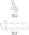
- holes 9are provided to the wood piece or wood form 10 before the layers of upholstery material are applied and T-nuts 11 are secured to outside facing surface 12 of the wood form.
- An oblong spacer 13 with an oblong apertures 14 and a stapling tab 15is attached to the inside facing surface 16 of the wood form, with the holes positioned inside the elongate aperture, by stapling the tab.
- the upholstered layers of materialmay then be applied to the wood piece or form.
- the bulky oblong spacermust be avoided when applying the upholstery.
- the upholstered panel or formis then secured to the frame or mechanism with a bolt extending though a bracket or portion of the frame or mechanism, through the attached elongate spacer and into the T-nut that is secured to the outside surface of the wood form that is part of the upholstered panel or upholstered form.
- the inside surfaceis not generally exposed on the upholstered furniture.
- the oblong spaceris not conducive to automated assembly and uses more material than is necessary to effectively create space between the ottoman wood piece and the bracket. Also, it provides bulk that must be accommodated during the upholstery application.
- connectioncomprises a T-nut and a spacer configured as a bushing with a central bore and with two adjacent axial portions, a first portion of the spacer having a first lesser outside diameter and a second portion of the spacer having a second greater outside diameter.
- the T-nut and spacerattach on opposites sides of a wood form to be upholstered, the threaded barrel of the T-nut inserted in a hole through the wood form and with T-nut prongs embedding into a surface of the side of the wood form that will be facing outwardly on the furniture, the spacer is inserted into the hole at the opposite side of the wood form and is retained therein by an interference fit.
- the wood formis upholstered and is then attached to the furniture frame or mechanism with a bolt connecting to the furniture frame or mechanism and then extending through the spacer, into the hole and into the threaded barrel of the T-nut. The bolt is tightened compressing the wood form and spacer and the connection portion of the furniture frame of mechanism between the bolt head and the T-nut.
- the spacers described hereinmay be cylindrical or prismatic portions that receive a single bolt and are secured using an interference fit between the spacer and the wall of a hole a wood form and/or the barrel of a T-nut placed in the hole.
- the interference fitprevents the spacer from shifting or falling out of position while moved around during assembly.
- Using individual spacers that utilize an interference fit for each holedecreases the total amount of polymer material used for spacers compared to the conventional oblong spacer, uses less components, is less expensive, and is more conducive to automated assembly processes.
- connection systemin embodiments having a spacer, a T-nut, and a bolt.
- the spaceris polymeric and has two sections, an anchor portion and a separator portion.
- the anchor portionis cylindrical with a bore extending through the center.
- the outside diameter of the anchor portionis sized to create an interference fit with the ottoman wood form at the hole having an inside diameter less that the outside diameter of the anchor portion.
- the interior diameteris sized to create an interference fit with the outer diameter of the T-nut. In embodiments, only one of the two interference fits are required.
- the end of the anchor portionmay be chamfered on the inner or outer diameter or both.
- the height of the anchor portionis less than the thickness of the ottoman wood form.
- the separator portionis cylindrical or prismatic with an outer diameter larger than the outer diameter of the anchor portion and the diameter of the hole in the ottoman wood form. The difference in diameter provides a flat shoulder at the juncture that lies flush against the ottoman wood form when assembled. In embodiments a flange may be added at the juncture for more surface area engagement with the wood form.
- the length of the separator portionis determined by the desired space between the ottoman wood form and the bracket as the separator portion defines that distance.
- the anchor portion of the spaceris inserted into the hole in the ottoman wood form with the T-nut inside the bore of the anchor portion and the exterior diameter of the anchor portion is in contact with the inner diameter of the hole in the base.
- the shoulder of the separator portionis flush to the ottoman wood form.
- Upholsteryis applied over the ottoman wood form with the upholstery portion covering the side of the ottoman wood form with the flange of the T-nut.
- the boltis inserted through the hole in the bracket, the spacer, and the T-nut.
- the systemmay be assembled manually, by automation, or a combination of both.
- a recliner mechanism for a chair having a retractable ottomanhas a robust connection system as described herein for attaching an upholstered ottoman component, to the mechanism.
- the recliner mechanismextends the recliner from an upright seating position to a reclined position.
- the recliner mechanismhaving an ottoman bracket movable from a retracted tucked-in position below a seat, to an elevated outward position.
- the ottoman brackethaving a pair of spaced holes for attachment of the upholstered ottoman component.
- the upholstered ottoman componentcomprising an ottoman wood form, which may be a wood panel, with an upholstered side that is positioned on the outside of the recliner mechanism when the recliner is in the upright seating position and that faces upward when the recliner is in the reclined position so that the feet and/or legs of the user rest on the upholstered side.
- the ottoman wood formcovered with upholstery material and having a hole with the T-nut on an outside facing surface of the wood form, a spacer with cylindrical portions having an interference fit in the hole, and a bolt extending through the ottoman bracket, through the spacer, through the hole, and threadingly engaged with the T-nut.
- a feature and advantage of embodimentsis that the upholstered component is separated from the metal bracket, polymer spacers are sandwiched between the wood form and the metal bracket, the polymer providing a resilient contact surface, softer than metal, for making a secure engagement with the metal bracket and the wood form.
- a feature and advantage of embodimentsis that the surface area of the polymer spacers as described herein that contacts the wood form and metal bracket is minimized allowing facilitating direct contact between the spacer and the wood form. That is the spacer may extend through a relatively inconspicuous slit or hole in the upholstery without creating a significant visual anomaly. Additionally, where the upholstery is sandwiched between the spacer and the wood form, the minimal surface area of engagement allows compression of the minimal amount of upholstery, compared to the prior art spacers, and a more secure and uniform connection.
- FIG. 1is a side elevation view of a recliner in accord with embodiments.
- FIG. 2is a perspective view of an upholstered ottoman component suitable for the recliner of FIG. 1 .
- FIG. 3is a bottom view of the upholstered ottoman component of FIG. 2 .
- FIG. 4is a side elevational view of the ottoman component of FIGS. 2 and 3 .
- FIG. 5is a perspective view of a spacer from one end.
- FIG. 6is a perspective view of the spacer of FIG. 5 from an opposite end.
- FIG. 7is a cross sectional view of the spacer of FIGS. 5 and 6 .
- FIG. 8is a perspective view of a T-nut in accord with embodiments.
- FIG. 9 Ais a perspective view of a wood form before drilling holes in accord with embodiments.
- FIG. 9 Bis a perspective view of the wood form of FIG. 9 with holes therein.
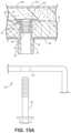
- FIG. 10is a cross sectional view of a T-nut and spacer engaged with a wood form in accord with embodiments.
- FIG. 11is a view of a wood form with spacers secured therein.
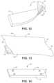
- FIG. 12is a view of a zippered upholstery case for securing to a wood form in accord with embodiments.
- FIG. 13is a view of upholstery layers comprising an outer upholstery layer and a foam layer.
- FIG. 14is the wood form of FIG. 11 which is suitably ready for application of one of the upholstery case of FIG. 12 or the upholstery layers of FIG. 13 .
- FIG. 15 Ais an exploded cross sectional view of a connection in accord with embodiments.
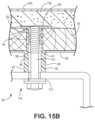
- FIG. 15 Bis the components of FIG. 15 A in an assembled state.
- FIG. 16is a schematic view of an automated assembly system in accord with embodiments.
- FIG. 17is a prior art view of a spacer.
- FIG. 18is a prior art view of a wood form with a spacer and T-nuts.
- an upholstered chair 20specifically a recliner, with a recliner mechanism 22 , is shown in an extended reclined position.
- the recliner mechanismhas an ottoman bracket 26 with an upholstered ottoman component 28 secured thereto by a connection system 30 .
- the upholstered component 28is further illustrated in FIGS. 2 - 4 separated from the recliner mechanism and has an upholstery case 34 .
- the casehas an outer upholstery layer 35 , a backing fabric 36 stitched to the upholstery layer 35 , and a zipper 38 .
- Spacers 40part of the connection system 30 , are illustrated extending through the case at apertures or slits 42 .
- the spacerhas a body 43 including two cylindrical portions, an anchor portion 44 , and a separator portion 46 , the separator portion 46 having an outside diameter D 1 that is greater than the outside diameter D 2 of the anchor portion 44 .
- a shoulder 47 with a stop surface 48extends between the anchor portion outer surface 50 and the separator portion outer surface 52 .
- a flange 53may be placed at the juncture 54 of the anchor portion 44 and separator portion 46 . See FIG. 7 .
- a bore 56 defined by an interior surface 57extends axially through the spacer body 43 .
- the end 58 of the spacermay have tapered surfaces 59 , 60 for facilitating installation as described below. See FIG. 6 .
- the spacer 40may be formed of a polymer material, for example, polyethylenes, polyurethanes, nylons, or the like, and may be injection molded.
- a T-nut 62part of the connection system 30 , has a flange portion 64 with a plurality of prongs 66 unitary with and extending therefrom and a unitary barrel portion 68 having an enlarged portion 70 with a diameter D 3 and a reduced diameter portion 72 with a diameter D 4 .
- the enlarged portion 70 and reduced diameter portion 72maybe generally cylindrical or may have a taper. In such a case, the average diameter D 3 of the enlarged portion is greater than the average diameter D 4 of the reduced diameter portion.
- Opposing prongshaving an inside dimension of D 5 .
- the barrel 68has a threaded inside wall 74 .
- T-nutsare commonly used in furniture construction and are stamped from metal.
- the T-nut barrelmay have nubs 75 or teeth projecting from the enlarged portion 70 to grab into the anchor portion.
- the prongs 66may have teeth or ridges to facilitate engagement with a surface.
- a wood form 78is cut to size for the particular upholstery application.
- Holes 80are drilled at the specific locations for attachment to the furniture frame including ottoman brackets on recliner mechanisms.
- the holesmay be constant diameter and, in embodiments, are sized for providing an interference fit with the anchor portions 44 of the spacers 40 and are oversized with respect to the barrel of the T-nuts and are undersized with respect to the inside dimension D 5 between opposing prongs.
- the wood formhas an inwardly facing surface 82 and an outwardly facing surface 84 .
- Hole 80has a length extending from inwardly facing surface 82 to outwardly facing surface 84 . In that the wood form portrayed is symmetrical about a plane through the form, there is no difference at this point which side is inwardly facing and which side is outwardly facing.
- FIGS. 10 and 11illustrate the connection system 30 components of the spacer 40 , T-nut 62 , and wood form 78 .
- the anchor portion 44having an interference fit with wood form 78 in the hole and also the enlarged portion 70 of the barrel 68 of the T-nut 62 .
- the anchor portion 44may have the interference fit with one of the wood form 78 and T-nut 62 but not the other.
- the anchor portion 44has a length less than the length of the hole.
- the anchor portion 44has a length more than one half of the length of the hole.
- the anchor portion 44has a length between 85 and 98 percent of the length of the hole.
- the end 58 of the anchor portion 44may have a taper or tapers 59 , 60 to act as guide-in surfaces for engagement with the T-nut 62 , as best shown in FIG. 6 .
- the spacer 40may be inserted into the hole 80 at the side of the wood form 78 that will face inwardly with respect to the furniture frame or mechanism to which it is attached before the T-nut 62 is installed to act as a guide for placement of the T-nut 62 .
- the spacer 40is inserted until the stop surface 48 of the shoulder 47 abuts up against the inside facing surface 82 of the wood form 78 .
- the T-nut 62is hammered to drive the prongs 66 into the wood form 78 guided by the spacer 40 .
- the spacer 40should be held in place allowing the barrel 68 to be driven into the anchor portion 44 .
- the spacers 40then extend from the holes as shown in FIG. 11 at the side 88 of the wood form 78 that will face inwardly when assembled with the furniture frame or mechanism.
- the inwardly facing side 88having the inwardly facing surface 82 .
- the side 90 and surface 84 that will face outwardlyis illustrated in FIG. 14 with the T-nut flanges 64 exposed on the outwardly facing surface 84 .
- the upholsterymay be pinched between the spacer shoulder 47 and the surface 82 .
- the upholstery case 34 of FIG. 12is assembled to the dimensions of the wood form and has an outer exposed upholstery material 35 , a backing fabric 36 stitched to the upholstery outer material, and a zipper 38 defining an opening 96 into which the wood form may be inserted.
- the casemay have additional upholstery layer or layers inside such as a foam layer.
- FIG. 13illustrates a piece of outwardly exposed upholstery material 100 that may be wrapped around the wood form with a layer of cushioning foam 102 between the wood form 78 and the upholstery material 100 .
- the edge portions 104may be attached to the inwardly facing surface 82 of the wood form 78 by staples.
- connection system 30such as also shown in FIG. 1 for attaching an upholstered component 28 , assembled as described above.
- the connection systemincludes a bolt 110 that extends through a hole 112 in a bracket, then is inserted into the spacer 40 that has previously been installed in the wood form 78 and is then threadably engaged with the threaded barrel 68 of the T-nut 62 .
- a lock nut 113may facilitate the integrity of the connection 114 .
- the separator portion 46may have a cylindrical outer surface 52 or may have a plurality of flats with a polygonal cross section.
- FIG. 16a schematic of an exemplary automated manufacturing system 150 is illustrated.
- the generally cylindrical spacers 40may be loaded into a hopper 156 and arranged through equipment 158 to be put into a line of the spacers to be conveyed by a conveyor 160 .
- a supply 166 or stack of wood forms 78are serially fed to a first work station 168 where the holes are drilled in the proper location.
- the wood forms 78 with holes 80are then serially conveyed to a second work station 172 where the spacers are installed at the to-be inwardly facing surface 82 and the T-nuts 62 are installed on the to-be outwardly facing surface 84 by pneumatics or the like.
- the anchor portion 44 of the spacer 40is inserted in the holes 80 and may be used as a guide for the precise alignment of the T-nut barrels 68 , or the equipment may be precise enough to center the T-nut barrel 68 in the hole 80 providing the proper annulus between the T-nut barrel 68 and wood form 78 , without the spacer 40 therein, to interferingly receive the anchor portion 44 of the spacer 40 .
- the T-nuts 62 and spacers 40may be forced in with a hammer action by the equipment. Tapered surfaces 59 , 60 may assist in the smooth entry of spacer 40 into hole 80 and further act as installation guides, such that barrel 68 slides within anchor portion as barrel 68 is forced within spacer 40 .
Landscapes
- Engineering & Computer Science (AREA)
- General Engineering & Computer Science (AREA)
- Mechanical Engineering (AREA)
- Connection Of Plates (AREA)
- Furniture Connections (AREA)
Abstract
Description
Claims (13)
Priority Applications (1)
| Application Number | Priority Date | Filing Date | Title |
|---|---|---|---|
| US17/374,824US11708848B2 (en) | 2018-04-30 | 2021-07-13 | Upholstered furniture component connection system |
Applications Claiming Priority (3)
| Application Number | Priority Date | Filing Date | Title |
|---|---|---|---|
| US201862664715P | 2018-04-30 | 2018-04-30 | |
| US16/399,444US11060547B2 (en) | 2018-04-30 | 2019-04-30 | Upholstered furniture component connection system |
| US17/374,824US11708848B2 (en) | 2018-04-30 | 2021-07-13 | Upholstered furniture component connection system |
Related Parent Applications (1)
| Application Number | Title | Priority Date | Filing Date |
|---|---|---|---|
| US16/399,444ContinuationUS11060547B2 (en) | 2018-04-30 | 2019-04-30 | Upholstered furniture component connection system |
Publications (2)
| Publication Number | Publication Date |
|---|---|
| US20220003260A1 US20220003260A1 (en) | 2022-01-06 |
| US11708848B2true US11708848B2 (en) | 2023-07-25 |
Family
ID=68292230
Family Applications (2)
| Application Number | Title | Priority Date | Filing Date |
|---|---|---|---|
| US16/399,444ActiveUS11060547B2 (en) | 2018-04-30 | 2019-04-30 | Upholstered furniture component connection system |
| US17/374,824ActiveUS11708848B2 (en) | 2018-04-30 | 2021-07-13 | Upholstered furniture component connection system |
Family Applications Before (1)
| Application Number | Title | Priority Date | Filing Date |
|---|---|---|---|
| US16/399,444ActiveUS11060547B2 (en) | 2018-04-30 | 2019-04-30 | Upholstered furniture component connection system |
Country Status (6)
| Country | Link |
|---|---|
| US (2) | US11060547B2 (en) |
| CN (1) | CN112040810B (en) |
| CA (1) | CA3093519A1 (en) |
| MX (1) | MX2020011346A (en) |
| MY (1) | MY207448A (en) |
| WO (1) | WO2019213121A1 (en) |
Families Citing this family (2)
| Publication number | Priority date | Publication date | Assignee | Title |
|---|---|---|---|---|
| US11060547B2 (en) | 2018-04-30 | 2021-07-13 | Ashley Furniture Industries, Llc | Upholstered furniture component connection system |
| IT201900021822A1 (en)* | 2019-11-21 | 2021-05-21 | Giuliano Rosini | COMPONENT FOR THE REALIZATION OF FRAMES OF BEDS, SOFAS, AND SIMILAR |
Citations (24)
| Publication number | Priority date | Publication date | Assignee | Title |
|---|---|---|---|---|
| US2528950A (en) | 1945-09-13 | 1950-11-07 | Royal Metal Mfg Company | Seat cushion cover construction |
| US3516633A (en) | 1968-04-15 | 1970-06-23 | Kansas City Plywood Co | Furniture leg mount |
| US3525549A (en) | 1968-07-19 | 1970-08-25 | La Z Boy Chair Co | Detachable chair back |
| US3700282A (en) | 1969-12-30 | 1972-10-24 | David L Rowland | Seating unit |
| US3799611A (en) | 1972-02-10 | 1974-03-26 | Shelby Williams Ind | Knock-down upholstered furniture |
| US4385783A (en) | 1979-05-11 | 1983-05-31 | Knoll International, Inc. | Upholstered furniture element |
| US4828324A (en) | 1983-11-21 | 1989-05-09 | Putnam Monroe P | Knockdown upholstered furniture construction |
| US5184871A (en) | 1990-11-30 | 1993-02-09 | La-Z-Boy Chair Co. | Detachable chair back |
| US5277476A (en) | 1992-06-16 | 1994-01-11 | John Caldwell | Knockdown article of furniture |
| US5478133A (en) | 1993-02-03 | 1995-12-26 | L&P Property Management Company | Motion furniture construction |
| US5678897A (en) | 1995-07-24 | 1997-10-21 | Ira S. Meyers | Ready-to-assemble upholstered furniture |
| US5820089A (en) | 1997-08-11 | 1998-10-13 | S.V. International Corporation | Furniture leg and method |
| US5904461A (en)* | 1998-05-07 | 1999-05-18 | Mckarge, Jr.; Gerald G. | Locking T-nut |
| US6241317B1 (en)* | 1999-11-30 | 2001-06-05 | Jimmy Wu | Modular chair construction |
| US6367880B1 (en)* | 1999-11-05 | 2002-04-09 | Alfred G. Niederman | Modular upholstered furniture construction |
| US6543828B1 (en) | 1997-11-17 | 2003-04-08 | Magna International Inc. | Projection welded panel spacer and method for making the same |
| US6854943B2 (en) | 2002-06-27 | 2005-02-15 | Nagayama Electronic Industry Co., Ltd. | T-nut |
| US20060182513A1 (en) | 2005-02-15 | 2006-08-17 | Dortch John P | Fastener and method for using same |
| US7189163B2 (en)* | 2003-06-09 | 2007-03-13 | Nagayama Electronic Industry Co., Ltd. | T-nut for hopper feeding having a projection |
| US20090016807A1 (en) | 2007-07-13 | 2009-01-15 | Jon Russell Koch | Assembly apparatus for modular components especially for upholstered furniture |
| US8061643B2 (en) | 2007-12-06 | 2011-11-22 | Andritz Inc. | Refiner plate fixtures for quick replacement, and methods and assemblies therefor |
| US8777319B2 (en) | 2011-03-30 | 2014-07-15 | Ashley Furniture Industries, Inc. | Furniture assembly system |
| US20140239698A1 (en) | 2013-01-29 | 2014-08-28 | Billy Joe Griggs, Jr. | Novel cam assembly utilizing 2 or more interconnected and locking parts for furniture |
| CN112040810A (en) | 2018-04-30 | 2020-12-04 | 阿希礼家具工业公司 | Connection system for upholstered furniture parts |
Family Cites Families (14)
| Publication number | Priority date | Publication date | Assignee | Title |
|---|---|---|---|---|
| BE475604A (en)* | 1946-08-28 | |||
| US3868079A (en)* | 1973-07-09 | 1975-02-25 | Westinghouse Electric Corp | Leveling foot assembly for a laundry appliance |
| US4549711A (en)* | 1983-12-07 | 1985-10-29 | Plastics Industries, Inc. | Non-cylindrical leg system particularly useful for upholstered furniture |
| US4681365A (en)* | 1986-04-30 | 1987-07-21 | Action Industries, Inc. | Multidirectionally resiliently releasing ottoman for motion chair |
| US4745867A (en)* | 1987-12-01 | 1988-05-24 | Lawnware Products, Inc. | Leg attachment bracket for pressboard tables |
| US5199117A (en)* | 1992-01-22 | 1993-04-06 | Kohler Co. | Seat attachment system |
| JP3233062B2 (en)* | 1997-02-04 | 2001-11-26 | コクヨ株式会社 | Chair mounting structure |
| US20060093457A1 (en)* | 2004-10-29 | 2006-05-04 | Tian-Fu Cao | T nut |
| US7674081B2 (en)* | 2006-09-19 | 2010-03-09 | Stafast Products, Inc. | Hopper fed tee-nut having counterbore with nylon lock |
| US9027178B2 (en)* | 2010-06-25 | 2015-05-12 | Sauder Manufacturing Co. | Sleep system |
| CN201723559U (en)* | 2010-08-12 | 2011-01-26 | 贵州航天精工制造有限公司 | Barrel-shaped floating self-locking nut connecting component |
| CN202338538U (en)* | 2011-11-21 | 2012-07-18 | 宝鸡石油机械有限责任公司 | Pressing device capable of limiting horizontal movement |
| CN103565136B (en)* | 2012-07-25 | 2016-06-15 | 姚本海 | A kind of assembly type plate wooden furniture and assemble method thereof |
| US10092106B2 (en)* | 2015-07-14 | 2018-10-09 | La-Z-Boy Incorporated | Recliner and legrest mechanism for a furniture member |
- 2019
- 2019-04-30USUS16/399,444patent/US11060547B2/enactiveActive
- 2019-04-30MYMYPI2020005282Apatent/MY207448A/enunknown
- 2019-04-30CNCN201980029001.XApatent/CN112040810B/enactiveActive
- 2019-04-30MXMX2020011346Apatent/MX2020011346A/enunknown
- 2019-04-30WOPCT/US2019/029977patent/WO2019213121A1/ennot_activeCeased
- 2019-04-30CACA3093519Apatent/CA3093519A1/enactivePending
- 2021
- 2021-07-13USUS17/374,824patent/US11708848B2/enactiveActive
Patent Citations (26)
| Publication number | Priority date | Publication date | Assignee | Title |
|---|---|---|---|---|
| US2528950A (en) | 1945-09-13 | 1950-11-07 | Royal Metal Mfg Company | Seat cushion cover construction |
| US3516633A (en) | 1968-04-15 | 1970-06-23 | Kansas City Plywood Co | Furniture leg mount |
| US3525549A (en) | 1968-07-19 | 1970-08-25 | La Z Boy Chair Co | Detachable chair back |
| US3700282A (en) | 1969-12-30 | 1972-10-24 | David L Rowland | Seating unit |
| US3799611A (en) | 1972-02-10 | 1974-03-26 | Shelby Williams Ind | Knock-down upholstered furniture |
| US4385783A (en) | 1979-05-11 | 1983-05-31 | Knoll International, Inc. | Upholstered furniture element |
| US4828324A (en) | 1983-11-21 | 1989-05-09 | Putnam Monroe P | Knockdown upholstered furniture construction |
| US5184871A (en) | 1990-11-30 | 1993-02-09 | La-Z-Boy Chair Co. | Detachable chair back |
| US5277476A (en) | 1992-06-16 | 1994-01-11 | John Caldwell | Knockdown article of furniture |
| US5478133A (en) | 1993-02-03 | 1995-12-26 | L&P Property Management Company | Motion furniture construction |
| US5678897A (en) | 1995-07-24 | 1997-10-21 | Ira S. Meyers | Ready-to-assemble upholstered furniture |
| US5820089A (en) | 1997-08-11 | 1998-10-13 | S.V. International Corporation | Furniture leg and method |
| US6543828B1 (en) | 1997-11-17 | 2003-04-08 | Magna International Inc. | Projection welded panel spacer and method for making the same |
| US5904461A (en)* | 1998-05-07 | 1999-05-18 | Mckarge, Jr.; Gerald G. | Locking T-nut |
| US6367880B1 (en)* | 1999-11-05 | 2002-04-09 | Alfred G. Niederman | Modular upholstered furniture construction |
| US6241317B1 (en)* | 1999-11-30 | 2001-06-05 | Jimmy Wu | Modular chair construction |
| US6854943B2 (en) | 2002-06-27 | 2005-02-15 | Nagayama Electronic Industry Co., Ltd. | T-nut |
| US7189163B2 (en)* | 2003-06-09 | 2007-03-13 | Nagayama Electronic Industry Co., Ltd. | T-nut for hopper feeding having a projection |
| US20060182513A1 (en) | 2005-02-15 | 2006-08-17 | Dortch John P | Fastener and method for using same |
| US20090016807A1 (en) | 2007-07-13 | 2009-01-15 | Jon Russell Koch | Assembly apparatus for modular components especially for upholstered furniture |
| US8356954B2 (en)* | 2007-07-13 | 2013-01-22 | Jon Russell Koch | Assembly apparatus for modular components especially for upholstered furniture |
| US8061643B2 (en) | 2007-12-06 | 2011-11-22 | Andritz Inc. | Refiner plate fixtures for quick replacement, and methods and assemblies therefor |
| US8777319B2 (en) | 2011-03-30 | 2014-07-15 | Ashley Furniture Industries, Inc. | Furniture assembly system |
| US20140239698A1 (en) | 2013-01-29 | 2014-08-28 | Billy Joe Griggs, Jr. | Novel cam assembly utilizing 2 or more interconnected and locking parts for furniture |
| CN112040810A (en) | 2018-04-30 | 2020-12-04 | 阿希礼家具工业公司 | Connection system for upholstered furniture parts |
| US11060547B2 (en)* | 2018-04-30 | 2021-07-13 | Ashley Furniture Industries, Llc | Upholstered furniture component connection system |
Non-Patent Citations (2)
| Title |
|---|
| Admitted Prior Art Spacer, prior to Apr. 30, 2018. |
| International Search Report for Application No. PCT/US2019/29977, dated Jul. 19, 2019 for (2 pages). |
Also Published As
| Publication number | Publication date |
|---|---|
| CA3093519A1 (en) | 2019-11-07 |
| CN112040810B (en) | 2024-06-18 |
| MY207448A (en) | 2025-02-27 |
| MX2020011346A (en) | 2020-11-24 |
| CN112040810A (en) | 2020-12-04 |
| US20190331159A1 (en) | 2019-10-31 |
| US11060547B2 (en) | 2021-07-13 |
| US20220003260A1 (en) | 2022-01-06 |
| WO2019213121A1 (en) | 2019-11-07 |
Similar Documents
| Publication | Publication Date | Title |
|---|---|---|
| US11708848B2 (en) | Upholstered furniture component connection system | |
| US8646843B2 (en) | Assembly apparatus for modular components especially for upholstered furniture | |
| AU2019309540B9 (en) | Upholstered furniture including molded furniture components | |
| US4893958A (en) | Joint for demountable furniture | |
| US10512338B1 (en) | Furniture assembly with metal seat stretcher | |
| US8505186B2 (en) | Method of fabricating a chair | |
| CN102726978A (en) | Furniture assembly system | |
| US6776380B1 (en) | Method and apparatus for adjustably mounting a furniture leg on an article of furniture | |
| WO2013078459A1 (en) | Ready to assembly furniture system | |
| AU2008202622A1 (en) | Furniture with decorative fasteners | |
| US4261667A (en) | Cove joints, furniture therefrom, and furniture manufacturing method | |
| US20050067876A1 (en) | Knockdown furniture assembly and method for making same | |
| US9125494B2 (en) | Ready to assemble modular upholstery | |
| US20040084951A1 (en) | Fastening system for chair | |
| DE10120621A1 (en) | Appliance for attaching covering fabric to upholstery comprises anchor piece, attachment element, with clips, catches or clamps | |
| US20200069068A1 (en) | Bed Platform | |
| US6349435B1 (en) | Bedrail attachments for engineered wood bedrail | |
| US11306760B2 (en) | Non-rotating T-nut and screw catch for use in a chair panel and method for using the same | |
| US7314251B1 (en) | Chair backrest attachment structure | |
| HK40040298A (en) | Upholstered furniture component connecton system | |
| US20070199272A1 (en) | No tool locking key-hole plug | |
| US6679645B2 (en) | Furniture support system | |
| US6173460B1 (en) | Bed rail hook and fastener assembly | |
| US7431249B2 (en) | Pound-in glide for an article of furniture | |
| WO2008107165A1 (en) | Connection mechanism for the connection of armrests to cosmetic tables or cosmetic chairs |
Legal Events
| Date | Code | Title | Description |
|---|---|---|---|
| FEPP | Fee payment procedure | Free format text:ENTITY STATUS SET TO UNDISCOUNTED (ORIGINAL EVENT CODE: BIG.); ENTITY STATUS OF PATENT OWNER: LARGE ENTITY | |
| STPP | Information on status: patent application and granting procedure in general | Free format text:DOCKETED NEW CASE - READY FOR EXAMINATION | |
| AS | Assignment | Owner name:ASHLEY FURNITURE INDUSTRIES, INC., WISCONSIN Free format text:ASSIGNMENT OF ASSIGNORS INTEREST;ASSIGNORS:WEBB, WILLIAM ROBERT;ANDERSON, ROGER JEFFREY;REEL/FRAME:058928/0048 Effective date:20190620 | |
| AS | Assignment | Owner name:ASHLEY FURNITURE INDUSTRIES, LLC, WISCONSIN Free format text:CORPORATE ENTITY CONVERSION;ASSIGNOR:ASHLEY FURNITURE INDUSTRIES, INC.;REEL/FRAME:058981/0295 Effective date:20201218 | |
| AS | Assignment | Owner name:ASHLEY FURNITURE INDUSTRIES, LLC, WISCONSIN Free format text:ENTITY CONVERSION;ASSIGNOR:ASHLEY FURNITURE INDUSTRIES, INC.;REEL/FRAME:059126/0422 Effective date:20201218 | |
| STPP | Information on status: patent application and granting procedure in general | Free format text:NON FINAL ACTION MAILED | |
| STPP | Information on status: patent application and granting procedure in general | Free format text:RESPONSE TO NON-FINAL OFFICE ACTION ENTERED AND FORWARDED TO EXAMINER | |
| STPP | Information on status: patent application and granting procedure in general | Free format text:NON FINAL ACTION MAILED | |
| STPP | Information on status: patent application and granting procedure in general | Free format text:PUBLICATIONS -- ISSUE FEE PAYMENT VERIFIED | |
| STCF | Information on status: patent grant | Free format text:PATENTED CASE |