US11707306B2 - Fixing bone plate - Google Patents
Fixing bone plateDownload PDFInfo
- Publication number
- US11707306B2 US11707306B2US15/580,714US201515580714AUS11707306B2US 11707306 B2US11707306 B2US 11707306B2US 201515580714 AUS201515580714 AUS 201515580714AUS 11707306 B2US11707306 B2US 11707306B2
- Authority
- US
- United States
- Prior art keywords
- plate
- bone
- fixing
- bone plate
- recited
- Prior art date
- Legal status (The legal status is an assumption and is not a legal conclusion. Google has not performed a legal analysis and makes no representation as to the accuracy of the status listed.)
- Active
Links
- 210000000988bone and boneAnatomy0.000titleclaimsabstractdescription145
- 229910052751metalInorganic materials0.000claimsabstractdescription13
- 239000002184metalSubstances0.000claimsabstractdescription13
- 238000000034methodMethods0.000claimsabstractdescription13
- 239000000654additiveSubstances0.000claimsabstractdescription7
- 230000000996additive effectEffects0.000claimsabstractdescription7
- 229910001069Ti alloyInorganic materials0.000claimsdescription10
- 239000000463materialSubstances0.000claimsdescription8
- 241000254032AcrididaeSpecies0.000claimsdescription5
- 238000005304joiningMethods0.000claimsdescription3
- 230000003319supportive effectEffects0.000claimsdescription3
- 229910000883Ti6Al4VInorganic materials0.000claims2
- 238000004519manufacturing processMethods0.000abstractdescription4
- 230000000877morphologic effectEffects0.000abstractdescription4
- 238000001356surgical procedureMethods0.000description20
- 238000010586diagramMethods0.000description9
- 206010061274MalocclusionDiseases0.000description4
- 210000003054facial boneAnatomy0.000description3
- 210000002050maxillaAnatomy0.000description3
- 208000006650OverbiteDiseases0.000description2
- 208000028911Temporomandibular Joint diseaseDiseases0.000description2
- 230000001815facial effectEffects0.000description2
- 210000001983hard palateAnatomy0.000description2
- 238000012986modificationMethods0.000description2
- 230000004048modificationEffects0.000description2
- 230000002035prolonged effectEffects0.000description2
- 210000003625skullAnatomy0.000description2
- 206010009269Cleft palateDiseases0.000description1
- 206010010356Congenital anomalyDiseases0.000description1
- 208000029578Muscle diseaseDiseases0.000description1
- 208000021642Muscular diseaseDiseases0.000description1
- 206010043220Temporomandibular joint syndromeDiseases0.000description1
- 238000004873anchoringMethods0.000description1
- 206010009259cleft lipDiseases0.000description1
- 239000013065commercial productSubstances0.000description1
- 238000005520cutting processMethods0.000description1
- 238000005553drillingMethods0.000description1
- 230000000694effectsEffects0.000description1
- 210000005128keratinized epitheliumAnatomy0.000description1
- 239000012567medical materialSubstances0.000description1
- 230000002093peripheral effectEffects0.000description1
- 230000008569processEffects0.000description1
- 230000004044responseEffects0.000description1
- 238000007493shaping processMethods0.000description1
- 238000004088simulationMethods0.000description1
- 201000002859sleep apneaDiseases0.000description1
- 230000000638stimulationEffects0.000description1
- 210000001738temporomandibular jointAnatomy0.000description1
- 210000000216zygomaAnatomy0.000description1
Images


Classifications
- A—HUMAN NECESSITIES
- A61—MEDICAL OR VETERINARY SCIENCE; HYGIENE
- A61B—DIAGNOSIS; SURGERY; IDENTIFICATION
- A61B17/00—Surgical instruments, devices or methods
- A61B17/56—Surgical instruments or methods for treatment of bones or joints; Devices specially adapted therefor
- A61B17/58—Surgical instruments or methods for treatment of bones or joints; Devices specially adapted therefor for osteosynthesis, e.g. bone plates, screws or setting implements
- A61B17/68—Internal fixation devices, including fasteners and spinal fixators, even if a part thereof projects from the skin
- A61B17/80—Cortical plates, i.e. bone plates; Instruments for holding or positioning cortical plates, or for compressing bones attached to cortical plates
- A61B17/8061—Cortical plates, i.e. bone plates; Instruments for holding or positioning cortical plates, or for compressing bones attached to cortical plates specially adapted for particular bones
- A61B17/8071—Cortical plates, i.e. bone plates; Instruments for holding or positioning cortical plates, or for compressing bones attached to cortical plates specially adapted for particular bones for the jaw
- A—HUMAN NECESSITIES
- A61—MEDICAL OR VETERINARY SCIENCE; HYGIENE
- A61B—DIAGNOSIS; SURGERY; IDENTIFICATION
- A61B17/00—Surgical instruments, devices or methods
- A—HUMAN NECESSITIES
- A61—MEDICAL OR VETERINARY SCIENCE; HYGIENE
- A61B—DIAGNOSIS; SURGERY; IDENTIFICATION
- A61B17/00—Surgical instruments, devices or methods
- A61B17/56—Surgical instruments or methods for treatment of bones or joints; Devices specially adapted therefor
- A61B17/58—Surgical instruments or methods for treatment of bones or joints; Devices specially adapted therefor for osteosynthesis, e.g. bone plates, screws or setting implements
- A61B17/68—Internal fixation devices, including fasteners and spinal fixators, even if a part thereof projects from the skin
- A61B17/80—Cortical plates, i.e. bone plates; Instruments for holding or positioning cortical plates, or for compressing bones attached to cortical plates
- A61B17/8028—Cushions, i.e. elements forming interface between bone plate and bone
- A—HUMAN NECESSITIES
- A61—MEDICAL OR VETERINARY SCIENCE; HYGIENE
- A61B—DIAGNOSIS; SURGERY; IDENTIFICATION
- A61B17/00—Surgical instruments, devices or methods
- A61B17/56—Surgical instruments or methods for treatment of bones or joints; Devices specially adapted therefor
- A61B17/58—Surgical instruments or methods for treatment of bones or joints; Devices specially adapted therefor for osteosynthesis, e.g. bone plates, screws or setting implements
- A61B17/68—Internal fixation devices, including fasteners and spinal fixators, even if a part thereof projects from the skin
- A61B17/80—Cortical plates, i.e. bone plates; Instruments for holding or positioning cortical plates, or for compressing bones attached to cortical plates
- A61B17/8052—Cortical plates, i.e. bone plates; Instruments for holding or positioning cortical plates, or for compressing bones attached to cortical plates immobilised relative to screws by interlocking form of the heads and plate holes, e.g. conical or threaded
- A—HUMAN NECESSITIES
- A61—MEDICAL OR VETERINARY SCIENCE; HYGIENE
- A61B—DIAGNOSIS; SURGERY; IDENTIFICATION
- A61B17/00—Surgical instruments, devices or methods
- A61B17/56—Surgical instruments or methods for treatment of bones or joints; Devices specially adapted therefor
- A61B17/58—Surgical instruments or methods for treatment of bones or joints; Devices specially adapted therefor for osteosynthesis, e.g. bone plates, screws or setting implements
- A61B17/68—Internal fixation devices, including fasteners and spinal fixators, even if a part thereof projects from the skin
- A61B17/84—Fasteners therefor or fasteners being internal fixation devices
- A61B17/86—Pins or screws or threaded wires; nuts therefor
- A—HUMAN NECESSITIES
- A61—MEDICAL OR VETERINARY SCIENCE; HYGIENE
- A61B—DIAGNOSIS; SURGERY; IDENTIFICATION
- A61B17/00—Surgical instruments, devices or methods
- A61B2017/00004—(bio)absorbable, (bio)resorbable or resorptive
- A—HUMAN NECESSITIES
- A61—MEDICAL OR VETERINARY SCIENCE; HYGIENE
- A61B—DIAGNOSIS; SURGERY; IDENTIFICATION
- A61B17/00—Surgical instruments, devices or methods
- A61B2017/00526—Methods of manufacturing
- A—HUMAN NECESSITIES
- A61—MEDICAL OR VETERINARY SCIENCE; HYGIENE
- A61B—DIAGNOSIS; SURGERY; IDENTIFICATION
- A61B17/00—Surgical instruments, devices or methods
- A61B17/56—Surgical instruments or methods for treatment of bones or joints; Devices specially adapted therefor
- A61B2017/568—Surgical instruments or methods for treatment of bones or joints; Devices specially adapted therefor produced with shape and dimensions specific for an individual patient
- A—HUMAN NECESSITIES
- A61—MEDICAL OR VETERINARY SCIENCE; HYGIENE
- A61C—DENTISTRY; APPARATUS OR METHODS FOR ORAL OR DENTAL HYGIENE
- A61C7/00—Orthodontics, i.e. obtaining or maintaining the desired position of teeth, e.g. by straightening, evening, regulating, separating, or by correcting malocclusions
- A—HUMAN NECESSITIES
- A61—MEDICAL OR VETERINARY SCIENCE; HYGIENE
- A61L—METHODS OR APPARATUS FOR STERILISING MATERIALS OR OBJECTS IN GENERAL; DISINFECTION, STERILISATION OR DEODORISATION OF AIR; CHEMICAL ASPECTS OF BANDAGES, DRESSINGS, ABSORBENT PADS OR SURGICAL ARTICLES; MATERIALS FOR BANDAGES, DRESSINGS, ABSORBENT PADS OR SURGICAL ARTICLES
- A61L2430/00—Materials or treatment for tissue regeneration
- A61L2430/02—Materials or treatment for tissue regeneration for reconstruction of bones; weight-bearing implants
- A—HUMAN NECESSITIES
- A61—MEDICAL OR VETERINARY SCIENCE; HYGIENE
- A61L—METHODS OR APPARATUS FOR STERILISING MATERIALS OR OBJECTS IN GENERAL; DISINFECTION, STERILISATION OR DEODORISATION OF AIR; CHEMICAL ASPECTS OF BANDAGES, DRESSINGS, ABSORBENT PADS OR SURGICAL ARTICLES; MATERIALS FOR BANDAGES, DRESSINGS, ABSORBENT PADS OR SURGICAL ARTICLES
- A61L31/00—Materials for other surgical articles, e.g. stents, stent-grafts, shunts, surgical drapes, guide wires, materials for adhesion prevention, occluding devices, surgical gloves, tissue fixation devices
- A61L31/02—Inorganic materials
- A61L31/022—Metals or alloys
- A—HUMAN NECESSITIES
- A61—MEDICAL OR VETERINARY SCIENCE; HYGIENE
- A61L—METHODS OR APPARATUS FOR STERILISING MATERIALS OR OBJECTS IN GENERAL; DISINFECTION, STERILISATION OR DEODORISATION OF AIR; CHEMICAL ASPECTS OF BANDAGES, DRESSINGS, ABSORBENT PADS OR SURGICAL ARTICLES; MATERIALS FOR BANDAGES, DRESSINGS, ABSORBENT PADS OR SURGICAL ARTICLES
- A61L31/00—Materials for other surgical articles, e.g. stents, stent-grafts, shunts, surgical drapes, guide wires, materials for adhesion prevention, occluding devices, surgical gloves, tissue fixation devices
- A61L31/14—Materials characterised by their function or physical properties, e.g. injectable or lubricating compositions, shape-memory materials, surface modified materials
- A61L31/148—Materials at least partially resorbable by the body
- B—PERFORMING OPERATIONS; TRANSPORTING
- B22—CASTING; POWDER METALLURGY
- B22F—WORKING METALLIC POWDER; MANUFACTURE OF ARTICLES FROM METALLIC POWDER; MAKING METALLIC POWDER; APPARATUS OR DEVICES SPECIALLY ADAPTED FOR METALLIC POWDER
- B22F10/00—Additive manufacturing of workpieces or articles from metallic powder
- B22F10/20—Direct sintering or melting
- B—PERFORMING OPERATIONS; TRANSPORTING
- B33—ADDITIVE MANUFACTURING TECHNOLOGY
- B33Y—ADDITIVE MANUFACTURING, i.e. MANUFACTURING OF THREE-DIMENSIONAL [3-D] OBJECTS BY ADDITIVE DEPOSITION, ADDITIVE AGGLOMERATION OR ADDITIVE LAYERING, e.g. BY 3-D PRINTING, STEREOLITHOGRAPHY OR SELECTIVE LASER SINTERING
- B33Y10/00—Processes of additive manufacturing
- B—PERFORMING OPERATIONS; TRANSPORTING
- B33—ADDITIVE MANUFACTURING TECHNOLOGY
- B33Y—ADDITIVE MANUFACTURING, i.e. MANUFACTURING OF THREE-DIMENSIONAL [3-D] OBJECTS BY ADDITIVE DEPOSITION, ADDITIVE AGGLOMERATION OR ADDITIVE LAYERING, e.g. BY 3-D PRINTING, STEREOLITHOGRAPHY OR SELECTIVE LASER SINTERING
- B33Y80/00—Products made by additive manufacturing
- Y—GENERAL TAGGING OF NEW TECHNOLOGICAL DEVELOPMENTS; GENERAL TAGGING OF CROSS-SECTIONAL TECHNOLOGIES SPANNING OVER SEVERAL SECTIONS OF THE IPC; TECHNICAL SUBJECTS COVERED BY FORMER USPC CROSS-REFERENCE ART COLLECTIONS [XRACs] AND DIGESTS
- Y02—TECHNOLOGIES OR APPLICATIONS FOR MITIGATION OR ADAPTATION AGAINST CLIMATE CHANGE
- Y02P—CLIMATE CHANGE MITIGATION TECHNOLOGIES IN THE PRODUCTION OR PROCESSING OF GOODS
- Y02P10/00—Technologies related to metal processing
- Y02P10/25—Process efficiency
Definitions
- the present inventionrelates to a fixing bone plate, particularly to a fixing bone plate device used in dental surgery, orthognathic surgery and facial bone contouring surgery.
- Orthognathic surgeryis well-known for amending orthognathic and facial configuration and fixing problems in growth and development, improving sleep apnea, easing temporomandibular joint and muscle disorders (TMJ disorders), adjusting malocclusion led by bone problems, or performing surgeries when an orthodontic treatment is not able to rectify easily by dental braces; in addition, orthognathic surgery is also performed to treat congenital conditions such as cleft lip and cleft palate. Orthognathic surgery is performed by an oral and maxillofacial surgeon in collaboration with an orthodontist.
- the original palatine boneis cut open, adjusted, and then re-joined by using bone plates and bone nails for shaping, during which medical materials such as metal bone plates, screws, bone nails, or stainless wires are often required, so that the orthognathic and facial areas can be fixed and shaped.
- medical materialssuch as metal bone plates, screws, bone nails, or stainless wires are often required, so that the orthognathic and facial areas can be fixed and shaped.
- there is no standard metal bone plate existing currently that features a complete attachment to boneshence, the surgeon and the orthodontist will need to lock the bone plate based on experiences by hand to adjust the angle for locking the bone plate, which results in a prolonged operation and increases the degree of difficulty for surgery.
- TW201313207As disclosed in TW201313207, the joined angle between the plate and the bone is adjusted by rotating the hinge, which cannot precisely make sure of the location for cutting and the drilling position for the fixing bone plate as well. Therefore, TW201313207 is not able to align precisely the bone plate with the bone for a secured fixation as it cannot align precisely based on morphological characteristics of bones.
- Each bone screwhas an exposed section and an implanted section which communicate with each other.
- the exposed section of the bone screwhas a first pivot-locking portion, a closing portion and a second pivot-locking portion, with the first pivot-locking portion is adjacent to the implanted section of the bone screw, with the closing portion is set between the first pivot-locking portion and the second pivot-locking portion.
- the peripheral surface of the first pivot-locking portionis non-circle.
- the correcting boardhas a bridge-connecting section, a positioning section and a slew-closing section, with the bridge-connecting section is set between the positioning section and the slew-closing section, with the bridge-connecting section has at least one hooking portion, with the positioning section and the slew-closing section receives with the closing portion of the two bone screws.
- the two bone screwsare guided and screwed into appropriate position of the jawbone by operating with a surgical navigating device, to make the correcting board couple with the two bone screws.
- the correcting board and the bone screwsare not able to adjust the angle of bone plate to have the bone plate precisely attached to the bone, therefore, it is possibly that the patient may suffer from incorrect biting, overbite, poor bite and etc. after the surgery.
- a published patent TW I398241titled as “Dental maxillary microimplant, is made of a plate and a correction accessory.
- the plateis installed into a keratinized epithelium of a maxilla in a correction patient's mouth, and then first and second locking elements are passed through first and second locking holes formed at both ends of the plate respectively to secure the plate to the maxilla, and finally a third locking element is passed through a fourth locking hole formed on the correction accessory and a third locking hole formed on the plate to secure the correction accessory to the maxilla.
- the plate disclosed in TWI398241cannot solve the existing problem, that is, to align precisely the bone plate with the bone for a secured fixation as it cannot align precisely based on morphological characteristics of bones.
- the inventionaims at providing a fixing bone plate capable of being used in dental surgery, orthognathic surgery and facial bone contouring surgery, moreover, the fixing bone plate provided in the present invention is able to align precisely based on features of bones and attach securely thereon, thereby solving aforementioned problems in orthognathic surgery, that is, the oral and maxillofacial surgeon and the orthodontist need to manually adjust and lock the fixing bone plate.
- One purpose of the inventionis to provide a fixing bone plate, which can be used in dental surgery, orthognathic surgery and facial bone contouring surgery, and can attach to human bones based on bone features so as to achieve an effect of precisely positioning and securely attachment.
- Another purpose of the inventionis to provide a fixing bone plate, which includes an attachment portion having a bone attachment surface, and the bone attachment surface can be calculated by a computer process, so that the fixing bone plate can be designed to precisely align with and securely attach to human bones.
- the inventionprovides a fixing bone plate, which includes a plate body having a plate main part and a locking portion passing through the plate body, wherein the plate main part is connected to the locking portion at the corresponding two ends of the plate body.
- the plate bodyfurther includes an attachment portion disposed on the other side of the locking portion.
- the plate main partmay be a plane plate or a cured plate.
- the locking portionmay be an opening or a screw hole.
- the attachment portionmay be a guide pin or a pad.
- the bone attachment surfacemay be a plane surface or a curved surface.
- the plate bodymay be made of medical titanium alloys or bioabsorbable materials.
- the attachment portionmay be made of medical titanium alloys or bioabsorbable materials.
- the fixing bone platefurther includes an engagement device for securing the fixing bone plate onto bones.
- the engagement devicemay be a bone nail, a rivet or a screw.
- the plate body and the attachment portionare made by using laser additive manufacturing technique or 3D metal printing technique.
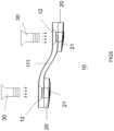
- FIG. 1is a plan schematic diagram of the fixing bone plate
- FIG. 2is a side viewed schematic diagram of the fixing bone plate
- FIG. 3is a parameter inputting diagram on simulation computer graphic software for the fixing bone plate
- FIG. 4is a 3D schematic diagram of the fixing bone plate
- FIG. 5is a combined schematic diagram combining the fixing bone plate with the engagement device
- FIG. 6is a combined schematic diagram of the fixing bone plate attached onto human bones.
- FIG. 1which is a plan schematic diagram
- FIG. 2which is a side viewed schematic diagram
- the fixing bone plate 10includes a plate body 11 with a plate main part 111 and a locking portion 12 passing through the plate body 11 .
- the plate main part 111is connected to the locking portion 12 at the corresponding two ends of the plate body 11 .
- the fixing bone plate 10also comprises an attachment portion 20 .
- the attachment portion 20is provided with a bone attachment surface 21 .
- the attachment portion 20is disposed on the other side of the locking portion 12 .
- the plate main part 111is a curved plate main part, which the degree of curvature and gradient of the curve can be calculated by using a computing software of a custom graphic user interface (GUI), such as GRASSHOPPER.
- GUIcustom graphic user interface
- the commercial product like GRASSHOPPERis used to calculate axial positions of X, Y, Z and angles.
- the stimulation computer software GRASSHOPPERcalculates parameters for manufacturing the plate main part 111 , and the metal laser additive manufacturing technique produces the plate main part 111 , thereby forming an outlook of a bridged-shaped supportive frame for the plate main part 111 .
- the locking portion 12 that is corresponding to the two ends of the plate body 11can be a screw hole, which is used to lock the fixing bone plate 10 .
- the attachment portion 20can be a guide pin, and the bone attachment surface 21 can be a curved surface.
- GUIcustom graphic user interface
- the fixing bone plate 10includes a plate body 11 with a plate main part 111 and a locking portion 12 passing through the plate body 11 .
- the plate main part 111is connected to the locking portion 12 at the corresponding two ends of the plate body 11 .
- the fixing bone plate 10also comprises an attachment portion 20 .
- the plate body 11is made of medical titanium alloys (Ti-6AI-4V)
- the attachment portion 20is made of medical titanium alloys (Ti-6AI-4V) as well.
- the plate main part 111may be replaced by a plane plate main part; the locking portion 12 may be replaced by an opening; the attachment portion 20 may be replaced by a pad; the bone attachment surface 21 may be replaced by a plane surface; the plate body 11 may be replaced by one kind of bioabsorbable materials; the attachment portion 20 may be replaced by one kind of bioabsorbable materials; and the plate body 11 and the attachment portion 20 may be manufactured using 3D metal printing technique.
- the fixing bone plate 10 in the present invention and an engagement device 30are combined as illustrated in FIG. 5 .
- the fixing bone plate 10includes a plate body 11 with a plate main part 111 and a locking portion 12 passing through the plate body 11 .
- the locking portion 12is arranged at two ends of the plate body 11 , and the plate main part 111 is used for connecting the locking portion 12 at the corresponding two ends of the plate body 11 .
- the fixing bone plate 10also comprises an attachment portion 20 , which is provided with a bone attachment surface 21 .
- the attachment portion 21is disposed on the other side of the locking portion 12 .
- the fixing bone plate 10further includes an engagement device 30 by which the fixing bone plate 10 is connected securely to human bones.
- the plate main part 111may be a curved plate main part, which the X, Y, and Z axial positions and angles can be calculated by a computer graphic interface software, and then manufactured by metal laser additive technique, thereby forming a bridged-shaped supportive appearance of the plate main part 111 .
- the locking portion 12 that corresponds to the two ends of the plate body 11may be a screw hole, which is able to lock the fixing bone plate 10 .
- the attachment portion 20may be a guide pin and has a bone attachment surface 21 , which may be a curved surface.
- the fixing bone plate 10further includes an engagement device 30 , by which the fixing bone plate 10 is fixed to human bones.
- the engagement device 30may be a bone nail
- the plate body 11may be made of medial titanium alloys (Ti-6AI-4V)
- the attachment portion 20may also be made of medial titanium alloys (Ti-6AI-4V).
- the plate main part 111may be replaced by a plane plate main part; the locking portion 12 may be replaced by an opening; the attachment portion 20 may be replaced by a pad; the bone attachment surface 21 may be replaced by a plane surface; the plate body 11 may be replaced by one kind of bioabsorbable materials; the attachment portion 20 may be replaced by one kind of bioabsorbable materials; the engagement device 30 may be replaced by a rivet or a screw; and the plate body 11 and the attachment portion 20 may be manufactured using 3D metal printing technique.
- the fixing bone plate 10is attached onto a human bone.
- boneneeds to be cut and adjusted and then re-joined by using a bone plate and bone nails to model the face.
- the fixing bone plate 10is fixed onto the skull 40 based on the features of upper/lower jaw and cheek bones by using bone nails, thereby precisely aligning the fixing bone plate 10 according to the morphological characteristics of the bone on the skull 40 in a secured manner.
Landscapes
- Health & Medical Sciences (AREA)
- Orthopedic Medicine & Surgery (AREA)
- Life Sciences & Earth Sciences (AREA)
- Surgery (AREA)
- Animal Behavior & Ethology (AREA)
- Veterinary Medicine (AREA)
- Public Health (AREA)
- General Health & Medical Sciences (AREA)
- Heart & Thoracic Surgery (AREA)
- Engineering & Computer Science (AREA)
- Medical Informatics (AREA)
- Biomedical Technology (AREA)
- Nuclear Medicine, Radiotherapy & Molecular Imaging (AREA)
- Molecular Biology (AREA)
- Neurology (AREA)
- Surgical Instruments (AREA)
- Epidemiology (AREA)
- Chemical & Material Sciences (AREA)
- Vascular Medicine (AREA)
- Materials Engineering (AREA)
- Inorganic Chemistry (AREA)
- Manufacturing & Machinery (AREA)
- Oral & Maxillofacial Surgery (AREA)
- Dentistry (AREA)
Abstract
Description
Claims (16)
Applications Claiming Priority (1)
| Application Number | Priority Date | Filing Date | Title |
|---|---|---|---|
| PCT/CN2015/081085WO2016197328A1 (en) | 2015-06-09 | 2015-06-09 | Fixing bone plate |
Publications (2)
| Publication Number | Publication Date |
|---|---|
| US20180185075A1 US20180185075A1 (en) | 2018-07-05 |
| US11707306B2true US11707306B2 (en) | 2023-07-25 |
Family
ID=57502883
Family Applications (1)
| Application Number | Title | Priority Date | Filing Date |
|---|---|---|---|
| US15/580,714ActiveUS11707306B2 (en) | 2015-06-09 | 2015-06-09 | Fixing bone plate |
Country Status (3)
| Country | Link |
|---|---|
| US (1) | US11707306B2 (en) |
| EP (1) | EP3308736B1 (en) |
| WO (1) | WO2016197328A1 (en) |
Families Citing this family (19)
| Publication number | Priority date | Publication date | Assignee | Title |
|---|---|---|---|---|
| US11166764B2 (en) | 2017-07-27 | 2021-11-09 | Carlsmed, Inc. | Systems and methods for assisting and augmenting surgical procedures |
| US11112770B2 (en) | 2017-11-09 | 2021-09-07 | Carlsmed, Inc. | Systems and methods for assisting a surgeon and producing patient-specific medical devices |
| US11083586B2 (en) | 2017-12-04 | 2021-08-10 | Carlsmed, Inc. | Systems and methods for multi-planar orthopedic alignment |
| US11432943B2 (en) | 2018-03-14 | 2022-09-06 | Carlsmed, Inc. | Systems and methods for orthopedic implant fixation |
| US11439514B2 (en) | 2018-04-16 | 2022-09-13 | Carlsmed, Inc. | Systems and methods for orthopedic implant fixation |
| USD958151S1 (en) | 2018-07-30 | 2022-07-19 | Carlsmed, Inc. | Display screen with a graphical user interface for surgical planning |
| WO2020056186A1 (en) | 2018-09-12 | 2020-03-19 | Carlsmed, Inc. | Systems and methods for orthopedic implants |
| EP3888095A4 (en) | 2018-11-29 | 2022-08-31 | Carlsmed, Inc. | SYSTEMS AND PROCEDURES FOR ORTHOPEDIC IMPLANTS |
| US11389209B2 (en)* | 2019-07-19 | 2022-07-19 | Medos International Sarl | Surgical plating systems, devices, and related methods |
| US10902944B1 (en) | 2020-01-06 | 2021-01-26 | Carlsmed, Inc. | Patient-specific medical procedures and devices, and associated systems and methods |
| US11376076B2 (en) | 2020-01-06 | 2022-07-05 | Carlsmed, Inc. | Patient-specific medical systems, devices, and methods |
| US12226315B2 (en) | 2020-08-06 | 2025-02-18 | Carlsmed, Inc. | Kinematic data-based patient-specific artificial discs, implants and associated systems and methods |
| WO2022109259A1 (en) | 2020-11-20 | 2022-05-27 | Carlsmed, Inc. | Patient-specific jig for personalized surgery |
| US12232980B2 (en) | 2021-06-08 | 2025-02-25 | Carlsmed, Inc. | Patient-specific expandable spinal implants and associated systems and methods |
| JP2024542048A (en) | 2021-11-01 | 2024-11-13 | カールスメッド インコーポレイテッド | Reduced Subsidence Spinal Implants and Surgical Procedures, and Related Systems and Methods - Patent application |
| US11443838B1 (en) | 2022-02-23 | 2022-09-13 | Carlsmed, Inc. | Non-fungible token systems and methods for storing and accessing healthcare data |
| US11806241B1 (en) | 2022-09-22 | 2023-11-07 | Carlsmed, Inc. | System for manufacturing and pre-operative inspecting of patient-specific implants |
| CN115568929B (en)* | 2022-09-28 | 2024-02-09 | 北京科技大学 | A customized degradable metal bone plate and its additive manufacturing method |
| US11793577B1 (en) | 2023-01-27 | 2023-10-24 | Carlsmed, Inc. | Techniques to map three-dimensional human anatomy data to two-dimensional human anatomy data |
Citations (32)
| Publication number | Priority date | Publication date | Assignee | Title |
|---|---|---|---|---|
| US4338926A (en)* | 1980-11-21 | 1982-07-13 | Howmedica, Inc. | Bone fracture prosthesis with controlled stiffness |
| US4403607A (en)* | 1980-05-09 | 1983-09-13 | The Regents Of The University Of California | Compatible internal bone fixation plate |
| US5013315A (en)* | 1985-07-12 | 1991-05-07 | Minnesota Mining And Manufacturing Company | Semiabsorbable bone plate spacer |
| US5108399A (en)* | 1988-09-17 | 1992-04-28 | Boehringer Ingelheim Gmbh | Device for osteosynthesis and process for producing it |
| US5474553A (en)* | 1989-04-18 | 1995-12-12 | Rainer Baumgart | System for setting tubular bone fractures |
| US5702396A (en)* | 1995-03-27 | 1997-12-30 | Hoenig; Johannes Franz | Osteosynthesis plate |
| US20020004660A1 (en)* | 2000-02-24 | 2002-01-10 | Stryker Instruments | Bioabsorbable plates. fasteners, tools and method of using same |
| US6344042B1 (en)* | 1998-05-12 | 2002-02-05 | Synthes (Usa) | Bone augmentation device |
| US20020128654A1 (en)* | 1998-02-18 | 2002-09-12 | Steger Shon D. | Method and apparatus for bone fracture fixation |
| US20030004515A1 (en)* | 1999-12-06 | 2003-01-02 | Raymond Curtis | Resorbable bone plate |
| US6533454B1 (en)* | 1999-09-30 | 2003-03-18 | Bionx Implants Oy | Surgical system for tissue fixation |
| US6738657B1 (en)* | 1998-07-06 | 2004-05-18 | Neutar L.L.C. | Customized surgical fixture |
| US20050177162A1 (en)* | 2002-07-23 | 2005-08-11 | Fondel Finance B.V. | Supporting element for attachment to bone |
| US20070162019A1 (en)* | 2005-12-21 | 2007-07-12 | Paul Burns | Resorbable anterior cervical plating system with screw retention mechanism |
| US20080114370A1 (en)* | 2006-06-09 | 2008-05-15 | Biomet Manufacturing Corp. | Patient-Specific Alignment Guide For Multiple Incisions |
| US20100004691A1 (en)* | 2008-07-02 | 2010-01-07 | Amato Matthew F | Growth control device |
| US20100130959A1 (en)* | 2008-10-15 | 2010-05-27 | Palmetto Biomedical, Inc. | Device and method for delivery of therapeutic agents via artificial internal implants |
| US20110178465A1 (en)* | 2008-10-15 | 2011-07-21 | Bioshape Solutions Inc | Device and method for delivery of therapeutic agents via internal implants |
| US20110269100A1 (en)* | 2010-04-29 | 2011-11-03 | Andre Furrer | Orthognathic implant and methods of use |
| US8241297B2 (en)* | 2007-04-10 | 2012-08-14 | Intelifuse, Inc. | Surgical drill guide for shape memory clamps |
| US20120285002A1 (en)* | 2011-05-13 | 2012-11-15 | Lin Ting-Sheng | Bone Plate Manufacturing Method |
| US20150051876A1 (en)* | 2011-12-14 | 2015-02-19 | Stryker Leibinger Gmbh & Co. Kg | Technique for generating a bone plate design |
| US20150051650A1 (en)* | 2012-04-18 | 2015-02-19 | Materialise N.V. | Orthopedic bone fixation systems and methods |
| US20150216571A1 (en)* | 2012-08-13 | 2015-08-06 | Biotech Ortho | Device for coaptation of bone fragments and methods for producing such a device |
| US20150327899A1 (en)* | 2014-05-15 | 2015-11-19 | Osteomed Llc | Ankle Tibia Plates |
| US20160192970A1 (en)* | 2015-01-07 | 2016-07-07 | Treace Medical Concepts, Inc. | Bone plating system and method |
| US20160287335A1 (en)* | 2013-11-12 | 2016-10-06 | Makoto Goto | Manufacturing method of bone cutting assist device, manufacturing program of bone cutting assist device, and bone cutting assist device |
| US20170143392A1 (en)* | 2014-08-21 | 2017-05-25 | Jeffrey Weinzweig | Bone fixation methods and devices including adhesive bioactive resorbable bone plates |
| US9675400B2 (en)* | 2011-04-19 | 2017-06-13 | Biomet Manufacturing, Llc | Patient-specific fracture fixation instrumentation and method |
| US20170231673A1 (en)* | 2014-07-09 | 2017-08-17 | National University Corporation Nagoya University | Locking Plate System for Treatment of Fracture of Distal Radius |
| US20180036050A1 (en)* | 2015-03-05 | 2018-02-08 | Kaushal Kant Mishra | Bone plate |
| US20180168811A1 (en)* | 2015-06-15 | 2018-06-21 | Rowan University | Novel biodegradable and non-biodegradable 3d printed implants as a drug delivery system |
Family Cites Families (9)
| Publication number | Priority date | Publication date | Assignee | Title |
|---|---|---|---|---|
| US5810823A (en)* | 1994-09-12 | 1998-09-22 | Synthes (U.S.A.) | Osteosynthetic bone plate and lock washer |
| US6989012B2 (en)* | 2002-07-16 | 2006-01-24 | Sdgi Holdings, Inc. | Plating system for stabilizing a bony segment |
| US9107712B2 (en)* | 2008-09-15 | 2015-08-18 | Biomet C.V. | Bone plate system for hand fractures and other small bones |
| US8435270B2 (en)* | 2010-04-29 | 2013-05-07 | Synthes Usa, Llc | Orthognathic implant and methods of use |
| EP2701620A1 (en)* | 2011-04-26 | 2014-03-05 | Synthes GmbH | Hinged fixation devices for combined upper jaw correction |
| TWI487508B (en)* | 2012-07-17 | 2015-06-11 | 義守大學 | Orthodontic treatment anchoring module and correcting board and surgical navigating device thereof |
| CN203619659U (en)* | 2013-09-29 | 2014-06-04 | 天津捷森特医疗器械制造有限公司 | Metal anatomical type bone fracture fixing plate |
| TWI584776B (en)* | 2014-06-13 | 2017-06-01 | Cheng-Xin She | A fixed bone plate |
| CN104382660B (en)* | 2014-11-10 | 2016-01-20 | 广州瑞通生物科技有限公司 | Customized tongue side orthodontic bracket and manufacturing method thereof |
- 2015
- 2015-06-09WOPCT/CN2015/081085patent/WO2016197328A1/ennot_activeCeased
- 2015-06-09USUS15/580,714patent/US11707306B2/enactiveActive
- 2015-06-09EPEP15894598.0Apatent/EP3308736B1/enactiveActive
Patent Citations (32)
| Publication number | Priority date | Publication date | Assignee | Title |
|---|---|---|---|---|
| US4403607A (en)* | 1980-05-09 | 1983-09-13 | The Regents Of The University Of California | Compatible internal bone fixation plate |
| US4338926A (en)* | 1980-11-21 | 1982-07-13 | Howmedica, Inc. | Bone fracture prosthesis with controlled stiffness |
| US5013315A (en)* | 1985-07-12 | 1991-05-07 | Minnesota Mining And Manufacturing Company | Semiabsorbable bone plate spacer |
| US5108399A (en)* | 1988-09-17 | 1992-04-28 | Boehringer Ingelheim Gmbh | Device for osteosynthesis and process for producing it |
| US5474553A (en)* | 1989-04-18 | 1995-12-12 | Rainer Baumgart | System for setting tubular bone fractures |
| US5702396A (en)* | 1995-03-27 | 1997-12-30 | Hoenig; Johannes Franz | Osteosynthesis plate |
| US20020128654A1 (en)* | 1998-02-18 | 2002-09-12 | Steger Shon D. | Method and apparatus for bone fracture fixation |
| US6344042B1 (en)* | 1998-05-12 | 2002-02-05 | Synthes (Usa) | Bone augmentation device |
| US6738657B1 (en)* | 1998-07-06 | 2004-05-18 | Neutar L.L.C. | Customized surgical fixture |
| US6533454B1 (en)* | 1999-09-30 | 2003-03-18 | Bionx Implants Oy | Surgical system for tissue fixation |
| US20030004515A1 (en)* | 1999-12-06 | 2003-01-02 | Raymond Curtis | Resorbable bone plate |
| US20020004660A1 (en)* | 2000-02-24 | 2002-01-10 | Stryker Instruments | Bioabsorbable plates. fasteners, tools and method of using same |
| US20050177162A1 (en)* | 2002-07-23 | 2005-08-11 | Fondel Finance B.V. | Supporting element for attachment to bone |
| US20070162019A1 (en)* | 2005-12-21 | 2007-07-12 | Paul Burns | Resorbable anterior cervical plating system with screw retention mechanism |
| US20080114370A1 (en)* | 2006-06-09 | 2008-05-15 | Biomet Manufacturing Corp. | Patient-Specific Alignment Guide For Multiple Incisions |
| US8241297B2 (en)* | 2007-04-10 | 2012-08-14 | Intelifuse, Inc. | Surgical drill guide for shape memory clamps |
| US20100004691A1 (en)* | 2008-07-02 | 2010-01-07 | Amato Matthew F | Growth control device |
| US20100130959A1 (en)* | 2008-10-15 | 2010-05-27 | Palmetto Biomedical, Inc. | Device and method for delivery of therapeutic agents via artificial internal implants |
| US20110178465A1 (en)* | 2008-10-15 | 2011-07-21 | Bioshape Solutions Inc | Device and method for delivery of therapeutic agents via internal implants |
| US20110269100A1 (en)* | 2010-04-29 | 2011-11-03 | Andre Furrer | Orthognathic implant and methods of use |
| US9675400B2 (en)* | 2011-04-19 | 2017-06-13 | Biomet Manufacturing, Llc | Patient-specific fracture fixation instrumentation and method |
| US20120285002A1 (en)* | 2011-05-13 | 2012-11-15 | Lin Ting-Sheng | Bone Plate Manufacturing Method |
| US20150051876A1 (en)* | 2011-12-14 | 2015-02-19 | Stryker Leibinger Gmbh & Co. Kg | Technique for generating a bone plate design |
| US20150051650A1 (en)* | 2012-04-18 | 2015-02-19 | Materialise N.V. | Orthopedic bone fixation systems and methods |
| US20150216571A1 (en)* | 2012-08-13 | 2015-08-06 | Biotech Ortho | Device for coaptation of bone fragments and methods for producing such a device |
| US20160287335A1 (en)* | 2013-11-12 | 2016-10-06 | Makoto Goto | Manufacturing method of bone cutting assist device, manufacturing program of bone cutting assist device, and bone cutting assist device |
| US20150327899A1 (en)* | 2014-05-15 | 2015-11-19 | Osteomed Llc | Ankle Tibia Plates |
| US20170231673A1 (en)* | 2014-07-09 | 2017-08-17 | National University Corporation Nagoya University | Locking Plate System for Treatment of Fracture of Distal Radius |
| US20170143392A1 (en)* | 2014-08-21 | 2017-05-25 | Jeffrey Weinzweig | Bone fixation methods and devices including adhesive bioactive resorbable bone plates |
| US20160192970A1 (en)* | 2015-01-07 | 2016-07-07 | Treace Medical Concepts, Inc. | Bone plating system and method |
| US20180036050A1 (en)* | 2015-03-05 | 2018-02-08 | Kaushal Kant Mishra | Bone plate |
| US20180168811A1 (en)* | 2015-06-15 | 2018-06-21 | Rowan University | Novel biodegradable and non-biodegradable 3d printed implants as a drug delivery system |
Also Published As
| Publication number | Publication date |
|---|---|
| US20180185075A1 (en) | 2018-07-05 |
| WO2016197328A1 (en) | 2016-12-15 |
| EP3308736A1 (en) | 2018-04-18 |
| EP3308736A4 (en) | 2019-02-20 |
| EP3308736B1 (en) | 2022-04-06 |
Similar Documents
| Publication | Publication Date | Title |
|---|---|---|
| US11707306B2 (en) | Fixing bone plate | |
| US5201736A (en) | Maxillofacial bone clamp | |
| Ko et al. | Characteristics and corrective outcome of face asymmetry by orthognathic surgery | |
| US11654000B2 (en) | Anteroposterior correction devices | |
| US11090160B2 (en) | Orthognathic implant assembly and method of use | |
| MXPA04010743A (en) | Compact maxillary distractor. | |
| US11213304B2 (en) | Surgery guiding bone plate | |
| KR102800060B1 (en) | Maxillary expander and protractor | |
| CN114760939B (en) | Surgical guide and implant with registration member | |
| WO2019178008A1 (en) | System and method for treating maxillary deficiencies | |
| CN105266878B (en) | Bone fixing plate | |
| JP7450846B2 (en) | Orthognathic surgical implant assembly with pre- and post-osteotomy alignment elements | |
| WO2023034160A1 (en) | Orthodontic appliances, system and method of producing and using the same | |
| Naini et al. | Principles of orthognathic surgical correction of skeletal anterior open bite | |
| Jin et al. | Le Fort I osteotomy as treatment for traumatic class III malocclusion caused by Le Fort III fracture: A case report | |
| CN105310791B (en) | Operation guide bone plate | |
| KR20210062154A (en) | Methods for patient-specific implants manufactured TMJ Replacement | |
| Kent et al. | Surgical Orthodontic Correction of Dentofacial Deformity | |
| Ferri et al. | Total Maxillary Set‐Back Osteotomy | |
| Piral | The gummy smile |
Legal Events
| Date | Code | Title | Description |
|---|---|---|---|
| FEPP | Fee payment procedure | Free format text:ENTITY STATUS SET TO UNDISCOUNTED (ORIGINAL EVENT CODE: BIG.); ENTITY STATUS OF PATENT OWNER: MICROENTITY | |
| FEPP | Fee payment procedure | Free format text:ENTITY STATUS SET TO SMALL (ORIGINAL EVENT CODE: SMAL); ENTITY STATUS OF PATENT OWNER: MICROENTITY Free format text:ENTITY STATUS SET TO MICRO (ORIGINAL EVENT CODE: MICR); ENTITY STATUS OF PATENT OWNER: MICROENTITY | |
| STPP | Information on status: patent application and granting procedure in general | Free format text:RESPONSE TO NON-FINAL OFFICE ACTION ENTERED AND FORWARDED TO EXAMINER | |
| STPP | Information on status: patent application and granting procedure in general | Free format text:FINAL REJECTION MAILED | |
| STPP | Information on status: patent application and granting procedure in general | Free format text:DOCKETED NEW CASE - READY FOR EXAMINATION | |
| STPP | Information on status: patent application and granting procedure in general | Free format text:NON FINAL ACTION MAILED | |
| STPP | Information on status: patent application and granting procedure in general | Free format text:RESPONSE TO NON-FINAL OFFICE ACTION ENTERED AND FORWARDED TO EXAMINER | |
| STPP | Information on status: patent application and granting procedure in general | Free format text:FINAL REJECTION MAILED | |
| STPP | Information on status: patent application and granting procedure in general | Free format text:DOCKETED NEW CASE - READY FOR EXAMINATION | |
| STPP | Information on status: patent application and granting procedure in general | Free format text:NON FINAL ACTION MAILED | |
| STPP | Information on status: patent application and granting procedure in general | Free format text:RESPONSE TO NON-FINAL OFFICE ACTION ENTERED AND FORWARDED TO EXAMINER | |
| STPP | Information on status: patent application and granting procedure in general | Free format text:EX PARTE QUAYLE ACTION MAILED | |
| STPP | Information on status: patent application and granting procedure in general | Free format text:PUBLICATIONS -- ISSUE FEE PAYMENT VERIFIED | |
| STCF | Information on status: patent grant | Free format text:PATENTED CASE |