US11705440B2 - Micro LED display panel - Google Patents
Micro LED display panelDownload PDFInfo
- Publication number
- US11705440B2 US11705440B2US17/224,053US202117224053AUS11705440B2US 11705440 B2US11705440 B2US 11705440B2US 202117224053 AUS202117224053 AUS 202117224053AUS 11705440 B2US11705440 B2US 11705440B2
- Authority
- US
- United States
- Prior art keywords
- sub
- pixel region
- micro
- micro led
- pixel
- Prior art date
- Legal status (The legal status is an assumption and is not a legal conclusion. Google has not performed a legal analysis and makes no representation as to the accuracy of the status listed.)
- Active, expires
Links
Images


Classifications
- H—ELECTRICITY
- H01—ELECTRIC ELEMENTS
- H01L—SEMICONDUCTOR DEVICES NOT COVERED BY CLASS H10
- H01L25/00—Assemblies consisting of a plurality of semiconductor or other solid state devices
- H01L25/03—Assemblies consisting of a plurality of semiconductor or other solid state devices all the devices being of a type provided for in a single subclass of subclasses H10B, H10D, H10F, H10H, H10K or H10N, e.g. assemblies of rectifier diodes
- H01L25/04—Assemblies consisting of a plurality of semiconductor or other solid state devices all the devices being of a type provided for in a single subclass of subclasses H10B, H10D, H10F, H10H, H10K or H10N, e.g. assemblies of rectifier diodes the devices not having separate containers
- H01L25/075—Assemblies consisting of a plurality of semiconductor or other solid state devices all the devices being of a type provided for in a single subclass of subclasses H10B, H10D, H10F, H10H, H10K or H10N, e.g. assemblies of rectifier diodes the devices not having separate containers the devices being of a type provided for in group H10H20/00
- H01L25/0753—Assemblies consisting of a plurality of semiconductor or other solid state devices all the devices being of a type provided for in a single subclass of subclasses H10B, H10D, H10F, H10H, H10K or H10N, e.g. assemblies of rectifier diodes the devices not having separate containers the devices being of a type provided for in group H10H20/00 the devices being arranged next to each other
- H—ELECTRICITY
- H01—ELECTRIC ELEMENTS
- H01L—SEMICONDUCTOR DEVICES NOT COVERED BY CLASS H10
- H01L25/00—Assemblies consisting of a plurality of semiconductor or other solid state devices
- H01L25/16—Assemblies consisting of a plurality of semiconductor or other solid state devices the devices being of types provided for in two or more different subclasses of H10B, H10D, H10F, H10H, H10K or H10N, e.g. forming hybrid circuits
- H01L25/167—Assemblies consisting of a plurality of semiconductor or other solid state devices the devices being of types provided for in two or more different subclasses of H10B, H10D, H10F, H10H, H10K or H10N, e.g. forming hybrid circuits comprising optoelectronic devices, e.g. LED, photodiodes
- H01L33/62—
- H—ELECTRICITY
- H10—SEMICONDUCTOR DEVICES; ELECTRIC SOLID-STATE DEVICES NOT OTHERWISE PROVIDED FOR
- H10H—INORGANIC LIGHT-EMITTING SEMICONDUCTOR DEVICES HAVING POTENTIAL BARRIERS
- H10H20/00—Individual inorganic light-emitting semiconductor devices having potential barriers, e.g. light-emitting diodes [LED]
- H10H20/80—Constructional details
- H10H20/85—Packages
- H10H20/857—Interconnections, e.g. lead-frames, bond wires or solder balls
Definitions
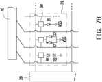
- both of the two red micro LEDsemit light
- in the second sub-pixel regiononly the another green micro LED emits light
- the blue micro LEDemits light
- the third sub-pixel regionis further provide another blue micro LED of the micro LEDs located on the second redundancy position and electrically connected in parallel with the blue micro LED of the micro LEDs.
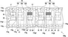
- the driving substratefurther includes a plurality of first-type electrode layers, a plurality of second-type electrode layers and a plurality of connecting layers.
- the first-type electrode layersincludes a plurality of first portions and a plurality of second portions. A first length of each of the first portions is smaller than a second length of each of the second portions.
- a portion of the second-type electrode layersincludes a plurality of protrusions.
- the first sub-pixel regionis provided with one of the first portions, one of the protrusions, and one of the connecting layers.
- the second sub-pixel region and the third sub-pixel regionare respectively provided with one of the second portions and one of the second-type electrode layers without the protrusions.
- the pixel regions P 2includes a first sub-pixel region S 21 , a second sub-pixel region S 22 and a third sub-pixel region S 23 , and sizes of the first sub-pixel region S 21 , the second sub-pixel region S 22 and the third sub-pixel region S 23 are the same.
- At least one of the sub-pixel regionsis provided with two micro LEDs of the plurality of micro LEDs electrically connected in series.
- the first sub-pixel region S 11 , S 21are respectively provided with two micro LEDs electrically connected in series, and a dominant wavelength of the two micro LEDs is within a wavelength range of a specific color light.
Landscapes
- Engineering & Computer Science (AREA)
- Microelectronics & Electronic Packaging (AREA)
- Power Engineering (AREA)
- Physics & Mathematics (AREA)
- Condensed Matter Physics & Semiconductors (AREA)
- General Physics & Mathematics (AREA)
- Computer Hardware Design (AREA)
- Devices For Indicating Variable Information By Combining Individual Elements (AREA)
Abstract
Description
Claims (9)
Priority Applications (1)
| Application Number | Priority Date | Filing Date | Title |
|---|---|---|---|
| US17/224,053US11705440B2 (en) | 2017-06-26 | 2021-04-06 | Micro LED display panel |
Applications Claiming Priority (4)
| Application Number | Priority Date | Filing Date | Title |
|---|---|---|---|
| TW106121222 | 2017-06-26 | ||
| TW106121222ATWI631694B (en) | 2017-06-26 | 2017-06-26 | Display panel |
| US16/018,080US20180374828A1 (en) | 2017-06-26 | 2018-06-26 | Micro led display panel |
| US17/224,053US11705440B2 (en) | 2017-06-26 | 2021-04-06 | Micro LED display panel |
Related Parent Applications (1)
| Application Number | Title | Priority Date | Filing Date |
|---|---|---|---|
| US16/018,080Continuation-In-PartUS20180374828A1 (en) | 2017-06-26 | 2018-06-26 | Micro led display panel |
Publications (2)
| Publication Number | Publication Date |
|---|---|
| US20210225817A1 US20210225817A1 (en) | 2021-07-22 |
| US11705440B2true US11705440B2 (en) | 2023-07-18 |
Family
ID=76857286
Family Applications (1)
| Application Number | Title | Priority Date | Filing Date |
|---|---|---|---|
| US17/224,053Active2038-10-08US11705440B2 (en) | 2017-06-26 | 2021-04-06 | Micro LED display panel |
Country Status (1)
| Country | Link |
|---|---|
| US (1) | US11705440B2 (en) |
Families Citing this family (5)
| Publication number | Priority date | Publication date | Assignee | Title |
|---|---|---|---|---|
| CN110098240B (en)* | 2019-05-21 | 2021-05-25 | 京东方科技集团股份有限公司 | Pixel structure, display device, pixel driving circuit and display control method |
| TWI742522B (en)* | 2020-01-30 | 2021-10-11 | 友達光電股份有限公司 | Display panel and manufacturing method thereof |
| KR102810559B1 (en)* | 2020-02-25 | 2025-05-22 | 엘지전자 주식회사 | Display device using semiconductor light emitting device and method for manufacturing the same |
| CN116314239A (en)* | 2023-03-30 | 2023-06-23 | 天马新型显示技术研究院(厦门)有限公司 | Display panel and display device |
| TWI889274B (en)* | 2024-04-03 | 2025-07-01 | 錼創顯示科技股份有限公司 | Micro light-emitting diode display device |
Citations (48)
| Publication number | Priority date | Publication date | Assignee | Title |
|---|---|---|---|---|
| US20080094006A1 (en)* | 2006-10-19 | 2008-04-24 | Samsung Electronics Co., Ltd. | Backlight assembly and display device having the same |
| US20090121652A1 (en)* | 2007-11-08 | 2009-05-14 | Eui-Jeong Kang | Light source module, backlight assembly having the same, display device having the same and method for reducing number of wires used in interconnect cable of the same |
| US20090267085A1 (en)* | 2005-03-11 | 2009-10-29 | Seoul Semiconductor Co., Ltd. | Led package having an array of light emitting cells coupled in series |
| US20110089810A1 (en)* | 2009-10-15 | 2011-04-21 | Intematix Technology Center Corp. | Light Emitting Diode Apparatus and Manufacturing Method Thereof |
| US20110299044A1 (en)* | 2009-06-22 | 2011-12-08 | Industrial Technology Research Institute | Projection apparatus |
| US20110309378A1 (en)* | 2009-12-09 | 2011-12-22 | Nano And Advanced Materials Institute Limited | Method for manufacturing a monolithic led micro-display on an active matrix panel using flip-chip technology and display apparatus having the monolithic led micro-display |
| US20120305949A1 (en)* | 2011-01-31 | 2012-12-06 | Matthew Donofrio | Light Emitting Diode (LED) Arrays Including Direct Die Attach And Related Assemblies |
| US20130002730A1 (en)* | 2011-06-30 | 2013-01-03 | Oki Data Corporation | Display module, manufacturing method thereof, and display device |
| US20130193453A1 (en)* | 2011-01-31 | 2013-08-01 | Matthew Donofrio | Light Emitting Diode (LED) Arrays Including Direct Die Attach And Related Assemblies |
| US20130208026A1 (en)* | 2012-02-10 | 2013-08-15 | Oki Data Corporation | Semiconductor light emitting apparatus, image displaying apparatus, mobile terminal, head-up display apparatus, image projector, head-mounted display apparatus, and image forming apparatus |
| US20130258663A1 (en)* | 2010-10-21 | 2013-10-03 | Optovate Limited | Illumination apparatus |
| US20140186979A1 (en)* | 2005-02-03 | 2014-07-03 | Epistar Corporation | Light emitting device and manufacture method thereof |
| CN104009187A (en) | 2014-05-29 | 2014-08-27 | 四川虹视显示技术有限公司 | Multicolor organic light emitting diode lighting (OLED) device |
| US9048368B2 (en)* | 2012-09-06 | 2015-06-02 | Lg Innotek Co., Ltd. | Light emitting device |
| US9159700B2 (en)* | 2012-12-10 | 2015-10-13 | LuxVue Technology Corporation | Active matrix emissive micro LED display |
| US20150295154A1 (en)* | 2005-02-03 | 2015-10-15 | Epistar Corporation | Light emitting device and manufacturing method thereof |
| US20150312461A1 (en)* | 2014-04-28 | 2015-10-29 | Tae Chan Kim | Image sensor including a pixel having photoelectric conversion elements and image processing device having the image sensor |
| US20150333230A1 (en)* | 2014-05-15 | 2015-11-19 | Lg Innotek Co., Ltd. | Light emitting device and light emitting device package including the same |
| US20150364443A1 (en)* | 2012-10-22 | 2015-12-17 | Sensor Electronic Technology, Inc. | Two Terminal Packaging |
| US20150371585A1 (en)* | 2014-06-18 | 2015-12-24 | X-Celeprint Limited | Micro assembled led displays and lighting elements |
| US20160128143A1 (en)* | 2013-05-22 | 2016-05-05 | Sharp Kabushiki Kaisha | Light source substrate, display apparatus, and light source substrate inspection method |
| US20160124269A1 (en)* | 2014-10-30 | 2016-05-05 | Samsung Display Co., Ltd. | Backlight unit having uniform brightness |
| US9337175B2 (en)* | 2008-09-30 | 2016-05-10 | Seoul Viosys Co., Ltd. | Light emitting device and method of fabricating the same |
| US20160181477A1 (en)* | 2014-08-27 | 2016-06-23 | Seoul Viosys Co., Ltd. | Light emitting diode and method of fabricating the same |
| US20160276326A1 (en)* | 2015-03-18 | 2016-09-22 | Kumaran Natarajan | Micro Solar Cell Powered Micro LED Display |
| US20160293811A1 (en)* | 2015-03-31 | 2016-10-06 | Cree, Inc. | Light emitting diodes and methods with encapsulation |
| US20160295144A1 (en)* | 2015-03-31 | 2016-10-06 | Renesas Electronics Corporation | Semiconductor device |
| US20160329376A1 (en)* | 2015-05-04 | 2016-11-10 | Samsung Electronics Co., Ltd. | Light emitting diode package |
| US20160358533A1 (en)* | 2014-09-25 | 2016-12-08 | X-Celeprint Limited | Self-compensating circuit for faulty display pixels |
| US20170025075A1 (en)* | 2015-07-23 | 2017-01-26 | X-Celeprint Limited | Parallel redundant chiplet system |
| US20170141155A1 (en)* | 2015-11-17 | 2017-05-18 | Oculus Vr, Llc | Redundancy in inorganic light emitting diode displays |
| CN106782128A (en) | 2017-01-24 | 2017-05-31 | 深圳市华星光电技术有限公司 | Micro- LED display panel and its manufacture method |
| US20170186740A1 (en)* | 2015-12-23 | 2017-06-29 | X-Celeprint Limited | Matrix-addressed device repair |
| US20170227169A1 (en)* | 2015-08-17 | 2017-08-10 | Zhejiang Super Lighting Electric Appliance Co., Ltd. | Led filament |
| US20170279020A1 (en)* | 2014-09-26 | 2017-09-28 | Seoul Viosys Co., Ltd. | Light emitting device and method of fabricating the same |
| US20170294418A1 (en)* | 2016-04-12 | 2017-10-12 | Cree, Inc. | High density pixelated led and devices and methods thereof |
| US20170365755A1 (en)* | 2016-05-25 | 2017-12-21 | Chen-Fu Chu | Methods of filling an organic or inorganic liquid in an assembly module |
| US20180159088A1 (en)* | 2016-12-02 | 2018-06-07 | PlayNitride Inc. | Display and repair method thereof |
| US20180198020A1 (en)* | 2017-01-10 | 2018-07-12 | PlayNitride Inc. | Micro light emitting diode chip and display panel |
| US20180226386A1 (en)* | 2017-02-08 | 2018-08-09 | X-Celeprint Limited | Inorganic light-emitting-diode displays with multi-iled pixels |
| US20180295683A1 (en)* | 2017-04-05 | 2018-10-11 | Epistar Corporation | Led driver and illumination system related to the same |
| US20180323180A1 (en)* | 2017-05-05 | 2018-11-08 | X-Celeprint Limited | Matrix-addressed tiles and arrays |
| US10153257B2 (en)* | 2016-03-03 | 2018-12-11 | X-Celeprint Limited | Micro-printed display |
| US20190006559A1 (en)* | 2017-06-30 | 2019-01-03 | PlayNitride Inc. | Micro light emitting diode and display panel |
| US20190006564A1 (en)* | 2014-10-31 | 2019-01-03 | eLux Inc. | Encapsulated Fluid Assembly Emissive Elements |
| US20190386185A1 (en)* | 2017-12-26 | 2019-12-19 | Jiaxing Super Lighting Electric Appliance Co., Ltd | Led filament and led light bulb |
| US20190394879A1 (en)* | 2018-06-25 | 2019-12-26 | Epistar Corporation | Light emitting device with extendable and flexible carrier |
| US10644195B2 (en)* | 2017-03-15 | 2020-05-05 | Boe Technology Group Co., Ltd. | Manufacturing method of light emitting diode device and light emitting diode device having light emitting units with each light emitting unit including second sub light emitting unit in tandem with first sub light emitting unit |
- 2021
- 2021-04-06USUS17/224,053patent/US11705440B2/enactiveActive
Patent Citations (51)
| Publication number | Priority date | Publication date | Assignee | Title |
|---|---|---|---|---|
| US20140186979A1 (en)* | 2005-02-03 | 2014-07-03 | Epistar Corporation | Light emitting device and manufacture method thereof |
| US20150295154A1 (en)* | 2005-02-03 | 2015-10-15 | Epistar Corporation | Light emitting device and manufacturing method thereof |
| US20090267085A1 (en)* | 2005-03-11 | 2009-10-29 | Seoul Semiconductor Co., Ltd. | Led package having an array of light emitting cells coupled in series |
| US20080094006A1 (en)* | 2006-10-19 | 2008-04-24 | Samsung Electronics Co., Ltd. | Backlight assembly and display device having the same |
| US20090121652A1 (en)* | 2007-11-08 | 2009-05-14 | Eui-Jeong Kang | Light source module, backlight assembly having the same, display device having the same and method for reducing number of wires used in interconnect cable of the same |
| US9337175B2 (en)* | 2008-09-30 | 2016-05-10 | Seoul Viosys Co., Ltd. | Light emitting device and method of fabricating the same |
| US20110299044A1 (en)* | 2009-06-22 | 2011-12-08 | Industrial Technology Research Institute | Projection apparatus |
| US20110089810A1 (en)* | 2009-10-15 | 2011-04-21 | Intematix Technology Center Corp. | Light Emitting Diode Apparatus and Manufacturing Method Thereof |
| US20110309378A1 (en)* | 2009-12-09 | 2011-12-22 | Nano And Advanced Materials Institute Limited | Method for manufacturing a monolithic led micro-display on an active matrix panel using flip-chip technology and display apparatus having the monolithic led micro-display |
| US20130258663A1 (en)* | 2010-10-21 | 2013-10-03 | Optovate Limited | Illumination apparatus |
| US20130193453A1 (en)* | 2011-01-31 | 2013-08-01 | Matthew Donofrio | Light Emitting Diode (LED) Arrays Including Direct Die Attach And Related Assemblies |
| US20120305949A1 (en)* | 2011-01-31 | 2012-12-06 | Matthew Donofrio | Light Emitting Diode (LED) Arrays Including Direct Die Attach And Related Assemblies |
| US9831220B2 (en)* | 2011-01-31 | 2017-11-28 | Cree, Inc. | Light emitting diode (LED) arrays including direct die attach and related assemblies |
| US20130002730A1 (en)* | 2011-06-30 | 2013-01-03 | Oki Data Corporation | Display module, manufacturing method thereof, and display device |
| US20130208026A1 (en)* | 2012-02-10 | 2013-08-15 | Oki Data Corporation | Semiconductor light emitting apparatus, image displaying apparatus, mobile terminal, head-up display apparatus, image projector, head-mounted display apparatus, and image forming apparatus |
| US9048368B2 (en)* | 2012-09-06 | 2015-06-02 | Lg Innotek Co., Ltd. | Light emitting device |
| US20150364443A1 (en)* | 2012-10-22 | 2015-12-17 | Sensor Electronic Technology, Inc. | Two Terminal Packaging |
| US9159700B2 (en)* | 2012-12-10 | 2015-10-13 | LuxVue Technology Corporation | Active matrix emissive micro LED display |
| US20160128143A1 (en)* | 2013-05-22 | 2016-05-05 | Sharp Kabushiki Kaisha | Light source substrate, display apparatus, and light source substrate inspection method |
| US20150312461A1 (en)* | 2014-04-28 | 2015-10-29 | Tae Chan Kim | Image sensor including a pixel having photoelectric conversion elements and image processing device having the image sensor |
| US20150333230A1 (en)* | 2014-05-15 | 2015-11-19 | Lg Innotek Co., Ltd. | Light emitting device and light emitting device package including the same |
| CN104009187A (en) | 2014-05-29 | 2014-08-27 | 四川虹视显示技术有限公司 | Multicolor organic light emitting diode lighting (OLED) device |
| US20150371585A1 (en)* | 2014-06-18 | 2015-12-24 | X-Celeprint Limited | Micro assembled led displays and lighting elements |
| US20150373793A1 (en)* | 2014-06-18 | 2015-12-24 | X-Celeprint Limited | Micro assembled led displays and lighting elements |
| US20160181477A1 (en)* | 2014-08-27 | 2016-06-23 | Seoul Viosys Co., Ltd. | Light emitting diode and method of fabricating the same |
| US20160358533A1 (en)* | 2014-09-25 | 2016-12-08 | X-Celeprint Limited | Self-compensating circuit for faulty display pixels |
| US20170279020A1 (en)* | 2014-09-26 | 2017-09-28 | Seoul Viosys Co., Ltd. | Light emitting device and method of fabricating the same |
| US20160124269A1 (en)* | 2014-10-30 | 2016-05-05 | Samsung Display Co., Ltd. | Backlight unit having uniform brightness |
| US20190006564A1 (en)* | 2014-10-31 | 2019-01-03 | eLux Inc. | Encapsulated Fluid Assembly Emissive Elements |
| US20160276326A1 (en)* | 2015-03-18 | 2016-09-22 | Kumaran Natarajan | Micro Solar Cell Powered Micro LED Display |
| US20160293811A1 (en)* | 2015-03-31 | 2016-10-06 | Cree, Inc. | Light emitting diodes and methods with encapsulation |
| US20160295144A1 (en)* | 2015-03-31 | 2016-10-06 | Renesas Electronics Corporation | Semiconductor device |
| US20160329376A1 (en)* | 2015-05-04 | 2016-11-10 | Samsung Electronics Co., Ltd. | Light emitting diode package |
| US20170025075A1 (en)* | 2015-07-23 | 2017-01-26 | X-Celeprint Limited | Parallel redundant chiplet system |
| US20170227169A1 (en)* | 2015-08-17 | 2017-08-10 | Zhejiang Super Lighting Electric Appliance Co., Ltd. | Led filament |
| US20170141155A1 (en)* | 2015-11-17 | 2017-05-18 | Oculus Vr, Llc | Redundancy in inorganic light emitting diode displays |
| US20170186740A1 (en)* | 2015-12-23 | 2017-06-29 | X-Celeprint Limited | Matrix-addressed device repair |
| US10153257B2 (en)* | 2016-03-03 | 2018-12-11 | X-Celeprint Limited | Micro-printed display |
| US20170294418A1 (en)* | 2016-04-12 | 2017-10-12 | Cree, Inc. | High density pixelated led and devices and methods thereof |
| US10312224B2 (en)* | 2016-04-12 | 2019-06-04 | Cree, Inc. | High density pixelated LED and devices and methods thereof |
| US20170365755A1 (en)* | 2016-05-25 | 2017-12-21 | Chen-Fu Chu | Methods of filling an organic or inorganic liquid in an assembly module |
| US20180159088A1 (en)* | 2016-12-02 | 2018-06-07 | PlayNitride Inc. | Display and repair method thereof |
| US20180198020A1 (en)* | 2017-01-10 | 2018-07-12 | PlayNitride Inc. | Micro light emitting diode chip and display panel |
| CN106782128A (en) | 2017-01-24 | 2017-05-31 | 深圳市华星光电技术有限公司 | Micro- LED display panel and its manufacture method |
| US20180226386A1 (en)* | 2017-02-08 | 2018-08-09 | X-Celeprint Limited | Inorganic light-emitting-diode displays with multi-iled pixels |
| US10644195B2 (en)* | 2017-03-15 | 2020-05-05 | Boe Technology Group Co., Ltd. | Manufacturing method of light emitting diode device and light emitting diode device having light emitting units with each light emitting unit including second sub light emitting unit in tandem with first sub light emitting unit |
| US20180295683A1 (en)* | 2017-04-05 | 2018-10-11 | Epistar Corporation | Led driver and illumination system related to the same |
| US20180323180A1 (en)* | 2017-05-05 | 2018-11-08 | X-Celeprint Limited | Matrix-addressed tiles and arrays |
| US20190006559A1 (en)* | 2017-06-30 | 2019-01-03 | PlayNitride Inc. | Micro light emitting diode and display panel |
| US20190386185A1 (en)* | 2017-12-26 | 2019-12-19 | Jiaxing Super Lighting Electric Appliance Co., Ltd | Led filament and led light bulb |
| US20190394879A1 (en)* | 2018-06-25 | 2019-12-26 | Epistar Corporation | Light emitting device with extendable and flexible carrier |
Non-Patent Citations (1)
| Title |
|---|
| "Office Action of China Counterpart Application", dated Nov. 4, 2022, p. 1-p. 6. |
Also Published As
| Publication number | Publication date |
|---|---|
| US20210225817A1 (en) | 2021-07-22 |
Similar Documents
| Publication | Publication Date | Title |
|---|---|---|
| US20180374828A1 (en) | Micro led display panel | |
| US11705440B2 (en) | Micro LED display panel | |
| US12155024B2 (en) | Display apparatus and manufacturing method thereof | |
| KR102411775B1 (en) | Led display apparatus having tft substrate where led driving units formed | |
| US11239122B2 (en) | Display module with improved electrical test and manufacturing method of the display module | |
| US10451257B2 (en) | Micro-light-emitting diode backlight system | |
| US10380930B2 (en) | Heterogeneous light emitter display system | |
| TWI616116B (en) | Display and its repair method | |
| US11978823B2 (en) | Display device, substrate for display device and method for repairing display device | |
| JP2017538959A (en) | Display, its LED chip, its pixel, its control method, and its computer program | |
| US20190013307A1 (en) | Microled display panel | |
| US20110157114A1 (en) | Electroluminescence device | |
| US10991301B2 (en) | Organic light-emitting display device | |
| TW202011629A (en) | MicroLED display panel | |
| US12159882B2 (en) | Display device | |
| US20230317704A1 (en) | Display panel and display device | |
| US20230307597A1 (en) | Display device using micro led | |
| US20240258482A1 (en) | Display device | |
| GB2627364A (en) | Display device | |
| US20230275200A1 (en) | Display device using semiconductor light-emitting element, and method for manufacturing same |
Legal Events
| Date | Code | Title | Description |
|---|---|---|---|
| FEPP | Fee payment procedure | Free format text:ENTITY STATUS SET TO UNDISCOUNTED (ORIGINAL EVENT CODE: BIG.); ENTITY STATUS OF PATENT OWNER: SMALL ENTITY | |
| AS | Assignment | Owner name:PLAYNITRIDE INC., TAIWAN Free format text:ASSIGNMENT OF ASSIGNORS INTEREST;ASSIGNORS:LIAO, KUAN-YUNG;LIN, CHING-LIANG;LI, YUN-LI;AND OTHERS;REEL/FRAME:055896/0694 Effective date:20210401 | |
| FEPP | Fee payment procedure | Free format text:ENTITY STATUS SET TO SMALL (ORIGINAL EVENT CODE: SMAL); ENTITY STATUS OF PATENT OWNER: SMALL ENTITY | |
| STPP | Information on status: patent application and granting procedure in general | Free format text:APPLICATION DISPATCHED FROM PREEXAM, NOT YET DOCKETED | |
| STPP | Information on status: patent application and granting procedure in general | Free format text:DOCKETED NEW CASE - READY FOR EXAMINATION | |
| STPP | Information on status: patent application and granting procedure in general | Free format text:NON FINAL ACTION MAILED | |
| STPP | Information on status: patent application and granting procedure in general | Free format text:RESPONSE TO NON-FINAL OFFICE ACTION ENTERED AND FORWARDED TO EXAMINER | |
| STPP | Information on status: patent application and granting procedure in general | Free format text:NON FINAL ACTION MAILED | |
| STCF | Information on status: patent grant | Free format text:PATENTED CASE | |
| STCF | Information on status: patent grant | Free format text:PATENTED CASE | |
| AS | Assignment | Owner name:PLAYNITRIDE DISPLAY CO., LTD., TAIWAN Free format text:ASSIGNMENT OF ASSIGNORS INTEREST;ASSIGNOR:PLAYNITRIDE INC.;REEL/FRAME:066912/0298 Effective date:20240319 |