US11704590B2 - Methods and systems for predicting failure of a power control unit of a vehicle - Google Patents
Methods and systems for predicting failure of a power control unit of a vehicleDownload PDFInfo
- Publication number
- US11704590B2 US11704590B2US15/468,618US201715468618AUS11704590B2US 11704590 B2US11704590 B2US 11704590B2US 201715468618 AUS201715468618 AUS 201715468618AUS 11704590 B2US11704590 B2US 11704590B2
- Authority
- US
- United States
- Prior art keywords
- control unit
- power control
- data
- machine learning
- simulated
- Prior art date
- Legal status (The legal status is an assumption and is not a legal conclusion. Google has not performed a legal analysis and makes no representation as to the accuracy of the status listed.)
- Active, expires
Links
Images


Classifications
- G—PHYSICS
- G06—COMPUTING OR CALCULATING; COUNTING
- G06N—COMPUTING ARRANGEMENTS BASED ON SPECIFIC COMPUTATIONAL MODELS
- G06N20/00—Machine learning
- B—PERFORMING OPERATIONS; TRANSPORTING
- B60—VEHICLES IN GENERAL
- B60W—CONJOINT CONTROL OF VEHICLE SUB-UNITS OF DIFFERENT TYPE OR DIFFERENT FUNCTION; CONTROL SYSTEMS SPECIALLY ADAPTED FOR HYBRID VEHICLES; ROAD VEHICLE DRIVE CONTROL SYSTEMS FOR PURPOSES NOT RELATED TO THE CONTROL OF A PARTICULAR SUB-UNIT
- B60W40/00—Estimation or calculation of non-directly measurable driving parameters for road vehicle drive control systems not related to the control of a particular sub unit, e.g. by using mathematical models
- B—PERFORMING OPERATIONS; TRANSPORTING
- B60—VEHICLES IN GENERAL
- B60W—CONJOINT CONTROL OF VEHICLE SUB-UNITS OF DIFFERENT TYPE OR DIFFERENT FUNCTION; CONTROL SYSTEMS SPECIALLY ADAPTED FOR HYBRID VEHICLES; ROAD VEHICLE DRIVE CONTROL SYSTEMS FOR PURPOSES NOT RELATED TO THE CONTROL OF A PARTICULAR SUB-UNIT
- B60W50/00—Details of control systems for road vehicle drive control not related to the control of a particular sub-unit, e.g. process diagnostic or vehicle driver interfaces
- B60W50/0097—Predicting future conditions
- B—PERFORMING OPERATIONS; TRANSPORTING
- B60—VEHICLES IN GENERAL
- B60W—CONJOINT CONTROL OF VEHICLE SUB-UNITS OF DIFFERENT TYPE OR DIFFERENT FUNCTION; CONTROL SYSTEMS SPECIALLY ADAPTED FOR HYBRID VEHICLES; ROAD VEHICLE DRIVE CONTROL SYSTEMS FOR PURPOSES NOT RELATED TO THE CONTROL OF A PARTICULAR SUB-UNIT
- B60W50/00—Details of control systems for road vehicle drive control not related to the control of a particular sub-unit, e.g. process diagnostic or vehicle driver interfaces
- B60W50/04—Monitoring the functioning of the control system
- B60W50/045—Monitoring control system parameters
- G—PHYSICS
- G05—CONTROLLING; REGULATING
- G05B—CONTROL OR REGULATING SYSTEMS IN GENERAL; FUNCTIONAL ELEMENTS OF SUCH SYSTEMS; MONITORING OR TESTING ARRANGEMENTS FOR SUCH SYSTEMS OR ELEMENTS
- G05B13/00—Adaptive control systems, i.e. systems automatically adjusting themselves to have a performance which is optimum according to some preassigned criterion
- G05B13/02—Adaptive control systems, i.e. systems automatically adjusting themselves to have a performance which is optimum according to some preassigned criterion electric
- G05B13/0205—Adaptive control systems, i.e. systems automatically adjusting themselves to have a performance which is optimum according to some preassigned criterion electric not using a model or a simulator of the controlled system
- G05B13/026—Adaptive control systems, i.e. systems automatically adjusting themselves to have a performance which is optimum according to some preassigned criterion electric not using a model or a simulator of the controlled system using a predictor
- G—PHYSICS
- G05—CONTROLLING; REGULATING
- G05B—CONTROL OR REGULATING SYSTEMS IN GENERAL; FUNCTIONAL ELEMENTS OF SUCH SYSTEMS; MONITORING OR TESTING ARRANGEMENTS FOR SUCH SYSTEMS OR ELEMENTS
- G05B13/00—Adaptive control systems, i.e. systems automatically adjusting themselves to have a performance which is optimum according to some preassigned criterion
- G05B13/02—Adaptive control systems, i.e. systems automatically adjusting themselves to have a performance which is optimum according to some preassigned criterion electric
- G05B13/0265—Adaptive control systems, i.e. systems automatically adjusting themselves to have a performance which is optimum according to some preassigned criterion electric the criterion being a learning criterion
- B—PERFORMING OPERATIONS; TRANSPORTING
- B60—VEHICLES IN GENERAL
- B60Y—INDEXING SCHEME RELATING TO ASPECTS CROSS-CUTTING VEHICLE TECHNOLOGY
- B60Y2200/00—Type of vehicle
- B60Y2200/90—Vehicles comprising electric prime movers
- B60Y2200/91—Electric vehicles
- B—PERFORMING OPERATIONS; TRANSPORTING
- B60—VEHICLES IN GENERAL
- B60Y—INDEXING SCHEME RELATING TO ASPECTS CROSS-CUTTING VEHICLE TECHNOLOGY
- B60Y2200/00—Type of vehicle
- B60Y2200/90—Vehicles comprising electric prime movers
- B60Y2200/92—Hybrid vehicles
- B—PERFORMING OPERATIONS; TRANSPORTING
- B60—VEHICLES IN GENERAL
- B60Y—INDEXING SCHEME RELATING TO ASPECTS CROSS-CUTTING VEHICLE TECHNOLOGY
- B60Y2306/00—Other features of vehicle sub-units
- B60Y2306/13—Failsafe arrangements
- Y—GENERAL TAGGING OF NEW TECHNOLOGICAL DEVELOPMENTS; GENERAL TAGGING OF CROSS-SECTIONAL TECHNOLOGIES SPANNING OVER SEVERAL SECTIONS OF THE IPC; TECHNICAL SUBJECTS COVERED BY FORMER USPC CROSS-REFERENCE ART COLLECTIONS [XRACs] AND DIGESTS
- Y10—TECHNICAL SUBJECTS COVERED BY FORMER USPC
- Y10S—TECHNICAL SUBJECTS COVERED BY FORMER USPC CROSS-REFERENCE ART COLLECTIONS [XRACs] AND DIGESTS
- Y10S903/00—Hybrid electric vehicles, HEVS
- Y10S903/902—Prime movers comprising electrical and internal combustion motors
- Y10S903/903—Prime movers comprising electrical and internal combustion motors having energy storing means, e.g. battery, capacitor
Definitions
- the present specificationgenerally relates to methods and systems for predicting a failure of a power control unit of a vehicle and, more specifically, to predicting a failure of a power control unit of a vehicle being subject to multi-load conditions by implementing machine learning algorithm, such as a K-Nearest Neighbors algorithm.
- machine learning algorithmsuch as a K-Nearest Neighbors algorithm.
- a power control unit of a hybrid or electric vehiclecontrols the operation of a motor-generator of the hybrid or electric vehicle.
- the power control unitmay require more reliable function in complicated systems involving, for example, autonomous driving in case of a failure. Thus, predicting a failure of the power control unit may be important in order to prevent any significant vehicle failures.
- a method for predicting a failure of a power control unit of a vehicleincludes obtaining data from a plurality of sensors of the power control unit of a vehicle subject to simulated multi-load conditions, implementing a machine learning algorithm on the data to obtain machine learning data, obtaining new data from the plurality of sensors of power control unit of the vehicle subject to real multi-load conditions, implementing the machine learning algorithm on the new data to obtain test data, predicting a failure of the power control unit based on a comparison between the test data and the machine learning data.
- a vehicle system for predicting a failure of a power control unit of a vehicleincludes a plurality of sensors configured to obtain data from the power control unit, and a machine learning electronic control unit.
- the machine learning electronic control unitincludes a processor and a non-transitory electronic memory storing computer readable and executable instructions.
- the computer readable and executable instructionswhen executed by the processor, cause the machine learning electronic control unit to: receive the data from the plurality of sensors of the vehicle being subject to simulated multi-load conditions; implement a machine learning algorithm on the data to obtain machine learning data; receive new data from the plurality of sensors of the vehicle being subject to real multi-load conditions; implement the machine learning algorithm on the new data to obtain test data; and predict a failure of the power control unit based on a comparison between the test data and the machine learning data.
- FIG. 1schematically depicts a vehicle system in accordance with one or more embodiments shown and described herein;
- FIG. 2schematically depicts collecting machine learning data from the power control unit being subject to simulated multi-load conditions in accordance with one or more embodiments shown and described herein;
- FIG. 3schematically depicts collecting machine learning data from the power control unit being subject to real multi-load conditions in accordance with one or more embodiments shown and described herein;
- FIG. 4depicts data clusters that are obtained from the power control unit subject to real multi-load conditions in accordance with another embodiment shown and described herein;
- FIG. 5depicts combination data clusters including data clusters obtained based on simulated multi-load conditions and data clusters obtained based on real multi-load conditions according to another embodiment shown and described herein;
- FIG. 6depicts a flowchart of a method for predicting a failure of a power control unit of a vehicle.
- FIG. 7schematically depicts a vehicle system including the ML ECU 130 that serves failure prediction as well as energy management/optimization in accordance with one or more embodiments shown herein.
- Embodiments described hereinrelate to methods and systems for predicting a failure of a power control unit of a vehicle being subject to multi-load conditions.
- the machine learning electronic control unitobtains data from a plurality of sensors of the power control unit of a vehicle being subject to simulated multi-load conditions, and implements machine learning algorithm on the data to obtain machine-learning data. Then, the machine learning electronic control unit obtains new data from the plurality of sensors of power control unit of the vehicle being subject to real multi-load conditions and implements machine learning algorithm on the new data to obtain test data. The machine learning electronic control unit predicts a failure of the power control unit based on a comparison between the test data and the machine learning data.
- Various embodiments of methods and systems for predicting a failure of a power control unit of a vehiclewill be described in further detail herein with specific reference to the appended drawings.
- the vehicle system 100may be a hybrid vehicle system or an electric vehicle system.
- the vehicle system 100includes a plurality of drive wheels 102 , a power train 110 , a power control unit (PCU) 120 , a machine learning (ML) electronic control unit (ECU) 130 , a motor electronic control unit 140 , a system control electronic control unit 150 , a user interface 160 , and a battery 170 .
- PCUpower control unit
- MLmachine learning
- ECUmachine learning
- motor electronic control unit 140a motor electronic control unit 140
- system control electronic control unit 150a user interface 160
- a battery 170a battery 170 .
- the power train 110includes a motor 112 .
- the power train 110includes a motor and a generator.
- the power train 110may include the motor 112 and an engine.
- the vehicle system 100may be driven by a drive force from the motor 112 .
- the PCU 120controls a power supplied to the motor 112 .
- the PCU 120includes a power module 122 and a plurality of sensors 124 , 126 , and 128 .
- the PCU 120may also include various other electronic components such as a gate drive hoard, inductors, a DC-DC converter, capacitors, a cooler, etc.
- the PCU 120may include one or more silicon carbide (SiC) power devices. The use of SiC power devices allows the size of the PCU 120 to be significantly reduced compared a PCU made based on Si devices.
- the power module 122may include an inverter that converts the DC from the battery 170 into an AC for driving the motor 112 and a DC-DC converter for conversion to 12V.
- the plurality of sensors 124 , 126 , and 128may include, without limitation, a temperature sensor for sensing the temperature of the power module 122 , a current sensor for sensing an electric current of the power module 122 , and a voltage sensor for sensing a voltage of the power module 122 .
- Data including the temperature, current, and voltage obtained by the plurality of sensor 124 , 126 , and 128is provided to the machine learning electronic control unit (ML ECU) 130 .
- ML ECUmachine learning electronic control unit
- the ML ECU 130includes a processor 132 and a non-transitory electronic memory 134 ,
- the processor 132may be any device capable of executing machine readable instructions. Accordingly, the processor 132 may be a controller, an integrated circuit, a microchip, a computer, or any other computing device.
- the processor 132is communicatively coupled to the other components of the vehicle system 100 . For example, the processor 132 receives data from the PCU 120 and transmits signal to the motor ECU 140 and the system control ECU 150 .
- the non-transitory electronic memory 134may comprise RAM, ROM, flash memories, hard drives, or any device capable of storing machine readable instructions such that the machine readable instructions can be accessed and executed by the processor 132 .
- the machine readable instructionsmay comprise logic or algorithm(s) written in any programming language of any generation (e.g., 1GL, 2GL, 3GL, 4GL, or 5GL) such as, for example, machine language that may be directly executed by the processor 132 , or assembly language, object-oriented programming (OOP), scripting languages, microcode, etc., that may be compiled or assembled into machine readable instructions and stored in the non-transitory electronic memory 134 .
- any programming language of any generatione.g., 1GL, 2GL, 3GL, 4GL, or 5GL
- OOPobject-oriented programming
- the machine readable instructionsmay be written in a hardware description language (HDL), such as logic implemented via either a field-programmable gate array (FPGA) configuration or an application-specific integrated circuit (ASIC), or their equivalents.
- HDLhardware description language
- FPGAfield-programmable gate array
- ASICapplication-specific integrated circuit
- the non-transitory electronic memory 134may store computer readable and executable instructions that, when executed by the processor 132 , causes the ML ECU 130 to implement various operations.
- the ML ECU 130receives the data from the plurality of sensors, and implements machine learning algorithm on the data to obtain machine learning data.
- the ML ECU 130stores the machine learning data in the non-transitory electronic memory 134 and continues to update the machine learning data by implementing machine learning algorithm to data obtained from the plurality of sensors subsequently.
- the machine learning algorithmmay be a K-Nearest Neighbors (KNN) algorithm.
- the ML ECU 130predicts the failure of the PCU 120 , which will be described in detail with reference to FIGS. 3 - 5 below.
- the ML ECU 130provides the failure prediction of the PCU 120 to the ECU 140 .
- the motor ECU 140controls the motor 112 by sending a control signal to the PCU 120 .
- the motor ECU 140may receive data including the temperature, current, and voltage obtained by the plurality of sensors 124 , 126 , and 128 , and provide the data to the ML ECU 130 .
- the motor ECU 140may include a processor and a non-transitory memory comparable to the processor 132 and the non-transitory electronic memory 134 of the ML ECU 130 .
- the system control ECU 150controls the overall system of the vehicle system 100 based on input signals from various components of the vehicle system 100 .
- the system control ECU 150collects input signals from various components of the vehicle system 100 , such as the motor 112 , the battery 170 , etc. and controls the components based on the collected signals.
- the system control ECU 150may include a processor and a non-transitory memory comparable to the processor 132 and the non-transitory electronic memory 134 of the ML ECU 130 .
- the user interface 160provides information on failure prediction of the PCU 120 to a user of the vehicle system 100 by displaying an image on a display, outputting a sound, or providing a tactile feedback. For example, when the user interface 160 receives a signal from the system control ECU 150 that the failure of the PCU 120 is predicted, the user interface 160 may alert the user of the vehicle system 100 by displaying an alert light on a dashboard of the vehicle, or making an alert sound.
- the battery 170is a battery pack constituted of a plurality of cells.
- the battery 170may be constituted of a plurality of battery modules connected in series, where the battery modules are each made up of a plurality of cells integrated into the battery module.
- the battery 170may be a lithium ion battery.
- the ML ECU 130may be communicatively coupled to a remote server 190 via the network 180 .
- the network 180is a personal area network that utilizes Bluetooth technology to communicatively couple the vehicle system 100 and the remote server 190 .
- the network 180may include one or more computer networks (e.g., a personal area network, a local area network, or a wide area network), cellular networks, satellite networks and/or a global positioning system and combinations thereof.
- the vehicle system 100can be communicatively coupled to the network 180 via a wide area network, via a local area network, via a personal area network, via a cellular network, via a satellite network, or the like.
- Suitable local area networksmay include wireless technologies such as, for example, wireless fidelity (Wi-Fi).
- Suitable personal area networksmay include wireless technologies such as, for example, IrDA, Bluetooth, Wireless USB, Z-Wave, ZigBee, and/or other near field communication protocols.
- Suitable cellular networksinclude, but are not limited to, technologies such as LTE, WiMAX, UMTS, CDMA, and GSM.
- the remote server 190may include a processor 192 , and a non-transitory electronic memory 194 .
- the processor 192may be processors similar to the processor 132 described above.
- the non-transitory electronic memory 194may be memory components similar to the non-transitory electronic memory 134 described above.
- the remote server 190may receive data include the temperature, current, and voltage of the PCU 120 , and implement the machine learning algorithm to determine whether a failure of the PCU 120 would occur.
- the PCU 120 in the vehicle system 100is subject to real multi-load conditions 104 .
- the real multi-load conditionsare a combination of various load conditions that affect the operation and life time of the PCU 120 .
- the real multi-load conditions 121may include a combination of a thermal condition, a power cycle, a shock, a vibration, etc.
- the PCU 120may be subject to a power cycle due to repetitive power on and off of the PCU 120 .
- the PCU 120may be subject to a varying temperature due to heat from elements of the vehicle system 100 , cooling operations by a cooler of the vehicle system 100 , or a varying external temperature.
- the PCU 120may be subject to a vibration condition due to various vibrations of the vehicle system 100 while driving, such as a vibration due to rough road conditions, a vibration due to wind, etc. These multi-load conditions significantly affect the likelihood of a failure of the PCU 120 .
- FIG. 2schematically depicts collecting machine learning data from the PCU 120 subject to simulated multi-load conditions.
- simulated multi-load conditionsmay be a combination of a simulated power cycle, a simulated thermal cycle, a simulated shock, a simulated vibration, etc.
- simulated multi-load conditions including a simulated power cycling 310 and a simulated thermal cycling 320are applied to the PCU 120 .
- the simulated power cycling 310is applied to the PCU 120 by repeatedly powering on and off the PCU 120 .
- the simulated thermal cycling 320is applied to the PCU 120 by repeatedly changing the temperature of a cooler of the PCU 120 .
- the plurality of sensors 124 , 126 and 128 of the PCU 120detect the temperature (T), voltage (V), and current (I) of the PCU 120 and send the data including the temperature, voltage and the current to the ML ECU 130 .
- the ML ECU 130then implements a machine learning algorithm, such as a K-Nearest Neighbors algorithm, on the data to obtain machine learning data, such as data clusters 330 , 340 , and 350 as shown in FIG. 2 .
- the ML ECU 130continues to collect data from the PCU 120 and updates the data clusters 330 , 340 and 350 as new data becomes available and removes erroneous and outlier data.
- the data cluster 330may be a cluster of machine learning data for temperature (T).
- the data cluster 340may be a cluster of machine learning data for voltage (V).
- the data cluster 350may be a cluster of machine learning data for current (I).
- the PCU 120is shown to be subject to the simulated power cycling 310 and the thermal cycling 320 in FIG. 2 , it can be subject to various other multi-load conditions and the data clusters 330 , 340 , and 350 are continuously updated.
- the PCU 120may be subject to simulated vibrations and shocks, and the plurality of sensors 124 , 126 and 128 detect the temperature (T), voltage (V), and current (I) of the PCU 120 being subjected to the simulated vibrations and shocks.
- the ML ECU 130receives the data including the temperature, voltage and the current and implements machine learning algorithm to update the data clusters 330 , 340 , and 350 in another example, the PCU 120 may be subject to a simulated power cycle, simulated vibrations, and simulated shocks, and the plurality of sensors 124 , 126 and 128 detect the temperature (T), voltage (V), and current (I) of the PCU 120 being subjected to the simulated power cycle, vibrations, and shocks.
- the ML ECU 130receives the data including the temperature, voltage and current and implements machine learning algorithm to update the data clusters 330 , 340 , and 350 .
- the PCU 120may be subject to a simulated power cycle, a simulated thermal cycle, simulated vibrations and simulated shocks, and the plurality of sensors 124 , 126 and 128 detects the temperature (T), voltage (V), and current (I) of the PCU 120 being subjected to the simulated power cycle, thermal cycle, vibrations and shocks.
- the ML ECU 130receives the data including the temperature, voltage, and current and implements machine learning algorithm to update the data clusters 330 , 340 , and 350 .
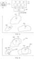
- FIG. 3schematically depicts collecting machine learning data from the PCU subject to real multi-load conditions.
- real multi-load conditionsmay be a combination of a real power cycle, a real thermal cycle, a real shock, a real vibration, etc.
- the vehicle system 100when the vehicle system 100 is on driving, it may be subject to a real shock and a real vibration due to external stresses such as air, road conditions, rains, etc.
- the vehicle system 100may be subject to a real power cycle due to ignition on/off, and a real thermal cycle due to changes of ambience temperature, and/or cooler temperature.
- real multi-load conditions 410are applied to the PCU 120 .
- the plurality of sensors 124 , 126 and 128 of the PCU 120detect the temperature (T), voltage (V), and current (I) of the PCU 120 and send the data including the temperature, voltage and the current to the ML ECU 130 .
- the ML ECU 130then implements machine learning algorithm, such as K-Nearest Neighbors algorithm to obtain machine learning data, such as data clusters 430 , 440 , and 450 as shown in FIG. 3 .
- the ML ECU 130continues to collect data from the PCU 120 and updates the data clusters 430 , 440 , and 450 as new data becomes available and removes erroneous and outlier data.
- the data cluster 430may be a cluster of machine learning data for temperature (T).
- the data cluster 440may be a cluster of machine learning data for voltage (V).
- the data cluster 450may be a cluster of machine learning data for current (I).
- the data clusters 430 , 440 , and 450are compared with the data clusters 330 , 340 , and 350 to determine whether a failure of the PCU 120 would occur.
- the data cluster 430is determined to be located outside of the boundaries of the data clusters 330 , 340 , and 350 , and the PCU 120 predicts the failure of the PCU 120 because the data cluster 430 is located outside the boundaries of the data clusters 330 , 340 , and 350 which are obtained during a normal operation of the PCU 120 being subject to various multi-load conditions.
- the data cluster 450is determined to be located outside the boundaries of the data clusters 330 , 340 , and 350 , and the PCU 120 predicts the failure of the PCU 120 .
- the data cluster 440is determined to be located within the boundary of the data cluster 340 , and the PCU 120 predicts no failure of the PCU 120 .
- the average value of each of the data clusters 430 , 440 , and 450is calculated. If the average value is within any of the boundaries of the data clusters 330 , 340 , and 350 , then the PCU may predict no failure of the PCU 120 .
- FIG. 4depicts data clusters 510 , 520 , and 530 that are obtained from the PCU 120 subject to real multi-load conditions in accordance with another embodiment shown and described herein.
- the plurality of sensors 124 , 126 and 128 of the PCU 120detect the temperature (T), voltage (V), and current (I) of the PCU 120 and send the data including the temperature, voltage and the current to the ML ECU 130 .
- the ML ECU 130then implements machine leanings algorithm, such as K-Nearest Neighbors algorithm to obtain machine learning data, such as data clusters 530 , 540 , and 550 as shown in FIG. 4 .
- the ML ECU 130calculates the average values 512 , 522 , and 532 of the data clusters 510 , 520 , and 530 , respectively.
- Each of the average values 512 , 522 , and 532may be a mean, median, or mode of the data clusters 510 , 520 , and 530 .
- the ML ECU 130calculates the standard deviation of each of the data clusters 510 , 520 , and 530 based on the average values 512 , 522 , and 532 . The greater the standard deviation is, the stronger the likelihood of abnormal operations of the PCU 120 is. If the standard deviation is greater than a certain threshold value, then the ML ECU 130 may determine that a failure of the PCU 120 would occur.
- FIG. 5depicts combination data clusters according to another embodiment shown and described herein.
- Combination data clusters 540 , 550 and 560include both the data clusters 330 , 340 , and 350 obtained based on simulated multi-load conditions and the data clusters 510 , 520 , and 530 obtained based on real multi-load conditions, respectively.
- the ML ECU 130calculates the average values 514 , 524 , and 534 of the combination data clusters 540 , 550 , and 560 , respectively.
- Each of the average values 514 , 524 , and 534 of the combination data clusters 540 , 550 , and 560may be a mean, median, or mode of the combination data clusters.
- the ML ECU 130calculates the standard deviation of each of the combination data clusters 540 , 550 , and 560 based on the average values 514 , 524 , and 534 . If the standard deviation is greater than a certain threshold value, then the ML ECU 130 may determine that a failure of the PCU 120 would occur.
- FIG. 6depicts a flowchart of a method for predicting a failure of a power control unit of a vehicle.
- the ML ECU 130 of the vehicle system 100obtains data from the plurality of sensors 124 , 126 , and 128 of the PCU 120 of the vehicle system 100 being subject to simulated multi-load conditions.
- Simulated multi-load conditionsmay be a combination of a simulated power cycle, a simulated thermal cycle, a simulated shock, a simulated vibration, etc.
- the ML ECU 130implements a machine learning algorithm on the data to obtain machine learning data.
- the machine learning dataincludes a plurality of data clusters.
- the ML ECU 130implements machine learning algorithm on the data including the temperature, voltage, and current of the PCU 120 to obtain the data clusters 330 , 340 , and 350 in FIG. 3 .
- the ML ECU 130may continue to collect data from the PCU 120 , update the data clusters 330 , 340 and 350 as new data becomes available, and remove erroneous and outlier data.
- the ML ECU 130obtains new data from the plurality of sensors 124 , 126 , and 128 of the PCU 120 of the vehicle system 100 being subject to real multi-load conditions.
- Real multi-load conditionsmay be a combination of a real power cycle, a real thermal cycle, a real shock, a real vibration, etc. applied to the vehicle system 100 while the vehicle system 100 is in operation.
- step 640the ML ECU 130 implements a machine learning algorithm on the new data to obtain test data.
- the machine learning algorithm used in step 640is the same as the machine learning algorithm used in step 620 .
- the ML ECU 130implements machine learning algorithm on the new data including the temperature, voltage, and current of the PCU 120 being subject to real multi-load conditions, and obtains test data, such as the data clusters 430 , 440 , and 450 shown in FIG. 4 .
- the ML ECU 130compares the test data obtained in step 640 with the machine learning data obtained in step 620 . In one embodiment, the ML ECU 130 determines whether each of the data clusters 430 , 440 , and 450 is within any of the boundaries of the data clusters 330 , 340 , and 350 obtained in step 620 . In another embodiment, the ML ECU 130 calculates an average value of the test data, and determines whether the average value is within any of the boundaries of the data clusters 330 , 340 , and 350 . In another embodiment, the ML ECU 130 calculates a standard deviation of the test data as shown in FIG. 5 .
- the ML ECU 130predicts a failure of the PCU 120 based on the comparison between the new data and the machine learning data. For example, if the test data (e.g., the data clusters 430 , 440 , and 450 ) is not within any of the boundaries of the data clusters 330 , 340 , and 350 , then the ML ECU 130 determines that a failure of the PCU 120 would occur. In another embodiment, if the standard deviation of the test data calculated in step 650 is greater than a certain threshold value, then the ML ECU 130 determines that a failure of the PCU 120 would occur. The ML ECU 130 may send an instruction to the user interface 160 for alerting a failure of the PCU 120 to a user.
- the test datae.g., the data clusters 430 , 440 , and 450
- FIG. 7schematically depicts a vehicle system including the ML ECU 130 that serves failure prediction as well as energy management/optimization in accordance with one or more embodiments shown herein.
- the ML ECU 130communicates with the system control ECU 150 with respect to the failure prediction of the PCU 120 . For example, if the ML ECU 130 determines that the PCU 120 would fail, then the ML ECU 130 sends a notification to the system control ECU 150 , which in turn sends a signal to the user interface 160 for notifying a user of the failure prediction.
- the system control ECU 150may adjust operations of components of the vehicle system 100 by sending instructions to, without limitation, the motor ECU 140 , a battery ECU 720 , and a brake ECU 730 .
- the system control ECU 150may send a command for adjusting a motor torque to the motor ECU 140 in response to the failure prediction from the ML ECU 130 .
- the system control ECU 150may send a command for adjusting a battery power to the battery ECU 720 in response to the failure prediction from the ML ECU 130 .
- the system control ECU 150may send a command for adjusting a regeneration required torque to the brake ECU 730 in response to the failure prediction from the ML ECU 130 .
- the ML ECU 130may provide energy optimization for the vehicle system 100 .
- the system control ECU 150collects data from the motor ECU 140 , the battery ECU 720 , and the brake ECU 730 , For example, the system control ECU 150 collects motor rotation data from the motor ECU 140 , the status of charge (SoC) from the battery ECU 720 , and a regeneration actual torque from the brake ECU 730 . Then, the system control ECU 150 transmits the collected data to the ML ECU 130 .
- the ML ECU 130implements machine learning algorithm for energy optimization and obtains optimized values for the motor torque, the battery power, and the regeneration required torque.
- the ML ECU 130transmits the optimized values for the motor torque, the battery power, and the regeneration required torque to the system control ECU 150 which instructs the motor ECU 140 , the battery ECU 720 , and the brake ECU 730 based on the motor torque, the battery power, and the regeneration required torque.
- a method for predicting a failure of a power control unit of a vehicleincludes obtaining data from a plurality of sensors of the power control unit of a vehicle subject to simulated multi-load conditions, implementing machine learning algorithm on the data to obtain machine learning data, obtaining new data from the plurality of sensors of power control unit of the vehicle subject to real multi-load conditions, implementing machine learning algorithm on the new data to obtain test data, predicting a failure of the power control unit based on a comparison between the test data and the machine learning data.
Landscapes
- Engineering & Computer Science (AREA)
- Automation & Control Theory (AREA)
- Software Systems (AREA)
- Artificial Intelligence (AREA)
- Physics & Mathematics (AREA)
- General Physics & Mathematics (AREA)
- Evolutionary Computation (AREA)
- Medical Informatics (AREA)
- Computer Vision & Pattern Recognition (AREA)
- Theoretical Computer Science (AREA)
- Mathematical Physics (AREA)
- Health & Medical Sciences (AREA)
- Transportation (AREA)
- Mechanical Engineering (AREA)
- Computing Systems (AREA)
- Data Mining & Analysis (AREA)
- General Engineering & Computer Science (AREA)
- Human Computer Interaction (AREA)
- Electric Propulsion And Braking For Vehicles (AREA)
- Computational Linguistics (AREA)
- Hybrid Electric Vehicles (AREA)
Abstract
Description
Claims (19)
Priority Applications (1)
| Application Number | Priority Date | Filing Date | Title |
|---|---|---|---|
| US15/468,618US11704590B2 (en) | 2017-03-24 | 2017-03-24 | Methods and systems for predicting failure of a power control unit of a vehicle |
Applications Claiming Priority (1)
| Application Number | Priority Date | Filing Date | Title |
|---|---|---|---|
| US15/468,618US11704590B2 (en) | 2017-03-24 | 2017-03-24 | Methods and systems for predicting failure of a power control unit of a vehicle |
Publications (2)
| Publication Number | Publication Date |
|---|---|
| US20180276546A1 US20180276546A1 (en) | 2018-09-27 |
| US11704590B2true US11704590B2 (en) | 2023-07-18 |
Family
ID=63583527
Family Applications (1)
| Application Number | Title | Priority Date | Filing Date |
|---|---|---|---|
| US15/468,618Active2040-08-13US11704590B2 (en) | 2017-03-24 | 2017-03-24 | Methods and systems for predicting failure of a power control unit of a vehicle |
Country Status (1)
| Country | Link |
|---|---|
| US (1) | US11704590B2 (en) |
Families Citing this family (6)
| Publication number | Priority date | Publication date | Assignee | Title |
|---|---|---|---|---|
| CN111891134B (en)* | 2019-05-06 | 2022-09-30 | 北京百度网讯科技有限公司 | Automatic driving processing system, system on chip and method for monitoring processing module |
| US20210216876A1 (en)* | 2020-01-15 | 2021-07-15 | Toyota Motor Engineering & Manufacturing North America, Inc. | Systems and methods for auto-encoder behavior modelling of vehicle components |
| US11353861B2 (en) | 2020-05-04 | 2022-06-07 | Toyota Motor Engineering & Manufacturing North America, Inc. | Autoencoder utilizing vehicle contextual information |
| EP4060576B1 (en)* | 2021-03-15 | 2024-12-25 | Volvo Truck Corporation | A method for identifying vehicle performance |
| US12379984B2 (en) | 2022-12-08 | 2025-08-05 | Toyota Motor Engineering & Manufacturing North America, Inc. | Remaining useful life determination for power electronic devices |
| US12073668B1 (en) | 2023-06-08 | 2024-08-27 | Mercedes-Benz Group AG | Machine-learned models for electric vehicle component health monitoring |
Citations (28)
| Publication number | Priority date | Publication date | Assignee | Title |
|---|---|---|---|---|
| US6907416B2 (en) | 2001-06-04 | 2005-06-14 | Honeywell International Inc. | Adaptive knowledge management system for vehicle trend monitoring, health management and preventive maintenance |
| US20060058932A1 (en)* | 2004-09-10 | 2006-03-16 | Ford Global Technologies, Llc | Prognostic method and system for hybrid and eletric vehicle components |
| US20060149519A1 (en) | 2004-11-15 | 2006-07-06 | Keller Jesse P | Hybrid vehicle parameters data collection and analysis for failure prediction and pre-emptive maintenance |
| US7260501B2 (en) | 2004-04-21 | 2007-08-21 | University Of Connecticut | Intelligent model-based diagnostics for system monitoring, diagnosis and maintenance |
| US20110130905A1 (en) | 2009-12-01 | 2011-06-02 | Ise Corporation | Remote Vehicle Monitoring and Diagnostic System and Method |
| US20120116696A1 (en) | 2009-03-24 | 2012-05-10 | Infinirel Corporation | Systems, devices and methods for predicting power electronics failure |
| US20120296512A1 (en)* | 2011-04-26 | 2012-11-22 | University Of Cincinnati | Method and system for electric vehicle battery prognostics and health management |
| US20130049454A1 (en)* | 2011-08-30 | 2013-02-28 | GM Global Technology Operations LLC | Prediction of transistor temperature in an inverter power module of a vehicle, and related operating methods |
| US20130090900A1 (en)* | 2011-10-10 | 2013-04-11 | Battelle Energy Alliance, Llc | Method, system, and computer-readable medium for determining performance characteristics of an object undergoing one or more arbitrary aging conditions |
| WO2013156791A1 (en) | 2012-04-19 | 2013-10-24 | Project Vanguard Limited | Machine analytic system and components thereof |
| US20130297141A1 (en)* | 2012-05-04 | 2013-11-07 | Chungbuk National University Industry-Academic Cooperation Foundation | Apparatus and method for monitoring abnormal state of vehicle using clustering technique |
| US8676432B2 (en) | 2010-01-13 | 2014-03-18 | GM Global Technology Operations LLC | Fault prediction framework using temporal data mining |
| US9050894B2 (en) | 2011-07-06 | 2015-06-09 | General Electric Company | System and method for predicting mechanical failure of a motor |
| US20150175010A1 (en)* | 2013-07-23 | 2015-06-25 | Atieva, Inc. | All-wheel drive electric vehicle motor torque safety monitor |
| US20150178997A1 (en)* | 2013-12-25 | 2015-06-25 | Denso Corporation | Vehicle diagnosis system and method |
| US20160116367A1 (en)* | 2013-06-03 | 2016-04-28 | Avl List Gmbh | Method for Reducing Vibrations in a Test Bed |
| US9384603B2 (en) | 2014-03-25 | 2016-07-05 | Hitachi High-Technologies Corporation | Failure cause classification apparatus |
| US9430882B2 (en) | 2013-10-11 | 2016-08-30 | Kenton Ho | Computerized vehicle maintenance management system with embedded stochastic modelling |
| US20160291114A1 (en)* | 2013-11-21 | 2016-10-06 | Commissariat à l'énergie atomique et aux énergies alternatives | Method for detecting a malfunction of a battery control system |
| US9495814B2 (en) | 2014-06-19 | 2016-11-15 | Atieva, Inc. | Vehicle fault early warning system |
| US20160349330A1 (en)* | 2015-06-01 | 2016-12-01 | Verizon Patent And Licensing Inc. | Systems and methods for determining vehicle battery health |
| US20170117725A1 (en)* | 2015-10-23 | 2017-04-27 | Oxfordian, Llc | Thermal Monitoring of Battery Packs |
| US20170131363A1 (en)* | 2014-06-18 | 2017-05-11 | Custom And Contract Power Solutions (Ccps) Limited | Improved Battery Testing Device |
| US20170146611A1 (en)* | 2015-11-23 | 2017-05-25 | GM Global Technology Operations LLC | Method and system for diagnosing battery system problems |
| US20180045771A1 (en)* | 2016-08-11 | 2018-02-15 | Hyundai Motor Company | Apparatus and method for predicting fault state of inverter |
| US20180204393A1 (en)* | 2017-01-18 | 2018-07-19 | Ford Global Technologies, Llc | Method for monitoring component life |
| US20180205121A1 (en)* | 2017-01-17 | 2018-07-19 | Ablerex Electronics Co., Ltd. | Battery State Detection Method and System Thereof |
| US20180257683A1 (en)* | 2017-03-09 | 2018-09-13 | General Electric Company | System for vehicle subsystem control |
- 2017
- 2017-03-24USUS15/468,618patent/US11704590B2/enactiveActive
Patent Citations (28)
| Publication number | Priority date | Publication date | Assignee | Title |
|---|---|---|---|---|
| US6907416B2 (en) | 2001-06-04 | 2005-06-14 | Honeywell International Inc. | Adaptive knowledge management system for vehicle trend monitoring, health management and preventive maintenance |
| US7260501B2 (en) | 2004-04-21 | 2007-08-21 | University Of Connecticut | Intelligent model-based diagnostics for system monitoring, diagnosis and maintenance |
| US20060058932A1 (en)* | 2004-09-10 | 2006-03-16 | Ford Global Technologies, Llc | Prognostic method and system for hybrid and eletric vehicle components |
| US20060149519A1 (en) | 2004-11-15 | 2006-07-06 | Keller Jesse P | Hybrid vehicle parameters data collection and analysis for failure prediction and pre-emptive maintenance |
| US20120116696A1 (en) | 2009-03-24 | 2012-05-10 | Infinirel Corporation | Systems, devices and methods for predicting power electronics failure |
| US20110130905A1 (en) | 2009-12-01 | 2011-06-02 | Ise Corporation | Remote Vehicle Monitoring and Diagnostic System and Method |
| US8676432B2 (en) | 2010-01-13 | 2014-03-18 | GM Global Technology Operations LLC | Fault prediction framework using temporal data mining |
| US20120296512A1 (en)* | 2011-04-26 | 2012-11-22 | University Of Cincinnati | Method and system for electric vehicle battery prognostics and health management |
| US9050894B2 (en) | 2011-07-06 | 2015-06-09 | General Electric Company | System and method for predicting mechanical failure of a motor |
| US20130049454A1 (en)* | 2011-08-30 | 2013-02-28 | GM Global Technology Operations LLC | Prediction of transistor temperature in an inverter power module of a vehicle, and related operating methods |
| US20130090900A1 (en)* | 2011-10-10 | 2013-04-11 | Battelle Energy Alliance, Llc | Method, system, and computer-readable medium for determining performance characteristics of an object undergoing one or more arbitrary aging conditions |
| WO2013156791A1 (en) | 2012-04-19 | 2013-10-24 | Project Vanguard Limited | Machine analytic system and components thereof |
| US20130297141A1 (en)* | 2012-05-04 | 2013-11-07 | Chungbuk National University Industry-Academic Cooperation Foundation | Apparatus and method for monitoring abnormal state of vehicle using clustering technique |
| US20160116367A1 (en)* | 2013-06-03 | 2016-04-28 | Avl List Gmbh | Method for Reducing Vibrations in a Test Bed |
| US20150175010A1 (en)* | 2013-07-23 | 2015-06-25 | Atieva, Inc. | All-wheel drive electric vehicle motor torque safety monitor |
| US9430882B2 (en) | 2013-10-11 | 2016-08-30 | Kenton Ho | Computerized vehicle maintenance management system with embedded stochastic modelling |
| US20160291114A1 (en)* | 2013-11-21 | 2016-10-06 | Commissariat à l'énergie atomique et aux énergies alternatives | Method for detecting a malfunction of a battery control system |
| US20150178997A1 (en)* | 2013-12-25 | 2015-06-25 | Denso Corporation | Vehicle diagnosis system and method |
| US9384603B2 (en) | 2014-03-25 | 2016-07-05 | Hitachi High-Technologies Corporation | Failure cause classification apparatus |
| US20170131363A1 (en)* | 2014-06-18 | 2017-05-11 | Custom And Contract Power Solutions (Ccps) Limited | Improved Battery Testing Device |
| US9495814B2 (en) | 2014-06-19 | 2016-11-15 | Atieva, Inc. | Vehicle fault early warning system |
| US20160349330A1 (en)* | 2015-06-01 | 2016-12-01 | Verizon Patent And Licensing Inc. | Systems and methods for determining vehicle battery health |
| US20170117725A1 (en)* | 2015-10-23 | 2017-04-27 | Oxfordian, Llc | Thermal Monitoring of Battery Packs |
| US20170146611A1 (en)* | 2015-11-23 | 2017-05-25 | GM Global Technology Operations LLC | Method and system for diagnosing battery system problems |
| US20180045771A1 (en)* | 2016-08-11 | 2018-02-15 | Hyundai Motor Company | Apparatus and method for predicting fault state of inverter |
| US20180205121A1 (en)* | 2017-01-17 | 2018-07-19 | Ablerex Electronics Co., Ltd. | Battery State Detection Method and System Thereof |
| US20180204393A1 (en)* | 2017-01-18 | 2018-07-19 | Ford Global Technologies, Llc | Method for monitoring component life |
| US20180257683A1 (en)* | 2017-03-09 | 2018-09-13 | General Electric Company | System for vehicle subsystem control |
Non-Patent Citations (16)
| Title |
|---|
| Antonopoulos et al. "Introducing a Silicon Carbide Inverter for Hybrid Electric Vehicles", 2008, 2008 IEEE Power Electronics Specialists Conference.* |
| Drobnik et al. "Electric and Hybrid Vehicle Power Electronics Efficiency, Testing and Reliability", 2013, World Electric Vehicle Journal, vol. 6.* |
| Gadalla et al. "A Survey on the Reliability of Power Electronics in Electro-Mobility Applications" 2015, 2015 Intl Aegean Conference on Electrical Machines & Power Electronics (ACEMP).* |
| Hooper et al. "Characterising the in-vehicle vibration inputs to the high voltage battery of an electric vehicle", 2014, Journal of Power Sources.* |
| Masrur et al. "Intelligent diagnosis of open and short circuit faults in electric drive inverters for real-time applications", 2010, IET Power Electron, vol. 3, Issue 2.* |
| N. Patil, D. Das, M. Pecht, Anomaly detection for IGBTs using Mahalanobis distance, Microelectronics Reliability 55, pp. 1054-1059, Apr. 2015. |
| Otto et al. "Reliability of New SiC BJT Power Modules for Fully Electric Vehicles", 2014, Advanced Microsystems for Automotive Applications.* |
| Peter Andrew James "Health Monitoring of IGBTs in Automotive Power Converter Systems", 2012, Thesis, University of Manchester, School of Electrical and Electronic Engineering.* |
| Sakka et al. "DC/DC converters for Electric Vehicles", 2011, Electric Vehicles, Open Access Peer Reviewed Edited Volume, retrihttps://www.intechopen.com/chapters/19583.* |
| Sankavaram et al. "Fault Diagnosis in Hybrid Electric Vehicle Regenerative Braking System", 2014, IEEE Access, vol. 2.* |
| Sheng et al. "Electric vehicle state of charge estimation: Nonlinear correlation and fuzzy support vector machine", 2015, Journal of Power Sources.* |
| Silva et al., "Fault Diagnosis in Electric Drives using Machine Learning Approaches", 2013, 2013 International Electric Machines & Drives Conference.* |
| Tabbache et al. "An improved fault-tolerant control scheme for PWM inverter-fed induction motor-based EVs", 2013, ISA Transactions.* |
| TechTarget Contributor, "duty cycle" Sep. 21, 2005, retrieved from https://www.techtarget.com/whatis/definition/duty-cycle?vgnextfmt=print.* |
| Ulatowski et al. "A Combinational-Logic Method for Electric Vehicle Drivetrain Fault Diagnosis", Mar./Apr. 2016, IEEE Transactions on Industry Applications, vol. 52, No. 2.* |
| You et al. "Real-time state-of-health estimation for electric vehicle batteries: A data-driven approach", 2016, Applied Energy.* |
Also Published As
| Publication number | Publication date |
|---|---|
| US20180276546A1 (en) | 2018-09-27 |
Similar Documents
| Publication | Publication Date | Title |
|---|---|---|
| US11704590B2 (en) | Methods and systems for predicting failure of a power control unit of a vehicle | |
| KR102180138B1 (en) | Wireless battery manamement system and method for protecting a battery back using the same | |
| CN108432030B (en) | Temperature monitoring device and method for battery pack | |
| JP4947934B2 (en) | Power conversion from a piezoelectric power supply with a multistage storage device | |
| CN111610459A (en) | System, method and storage medium for predicting the discharge curve of a battery pack | |
| US20150326038A1 (en) | System and method for battery power management | |
| KR20150137677A (en) | Method and apparatus for detecting condition of relay | |
| US20230182621A1 (en) | System and method for analyzing temperature changes in supercapacitor battery storage for electric vehicle | |
| US20140188304A1 (en) | Optimal electric vehicle battery recommendation system | |
| US20230223784A1 (en) | Supercapacitor system with temperature control | |
| US12151587B2 (en) | Power integrated circuit for electric vehicle applications | |
| KR20130093665A (en) | Electric vehicle battery system | |
| JP7389217B2 (en) | Battery condition prediction device and battery condition prediction method | |
| US11271418B2 (en) | Charging method that reduces aging of electrical energy store of a vehicle | |
| US20220266717A1 (en) | Controller integrated circuit for electric vehicle applications | |
| KR20180065741A (en) | System and method for calculating torch by vehicle control unit for high effectiveness network vehicle | |
| CN107636480B (en) | Parallel monitoring device for battery pack state | |
| KR20190073066A (en) | Apparatus and method for diagnosing current sensor error | |
| CN112706781A (en) | Method for monitoring and controlling a vehicle-mounted system and monitoring and control system | |
| US10218039B2 (en) | Method and apparatus for detecting state of safety plug | |
| US20160097821A1 (en) | Method for monitoring the state of a battery in a motor vehicle | |
| CN115020829B (en) | Thermal control method, device, equipment and storage medium for vehicle thermal management system | |
| EP4108508A1 (en) | Controller integrated circuit for electric vehicle applications | |
| JP2017117532A (en) | Battery abnormality detection device | |
| KR102107181B1 (en) | System for Monitoring ESC Driver for Drones |
Legal Events
| Date | Code | Title | Description |
|---|---|---|---|
| AS | Assignment | Owner name:TOYOTA MOTOR ENGINEERING & MANUFACTURING NORTH AMERICA, INC., KENTUCKY Free format text:ASSIGNMENT OF ASSIGNORS INTEREST;ASSIGNORS:JOSHI, SHAILESH;UKEGAWA, HIROSHI;DEDE, ERCAN M.;AND OTHERS;REEL/FRAME:041730/0097 Effective date:20170321 Owner name:TOYOTA MOTOR ENGINEERING & MANUFACTURING NORTH AME Free format text:ASSIGNMENT OF ASSIGNORS INTEREST;ASSIGNORS:JOSHI, SHAILESH;UKEGAWA, HIROSHI;DEDE, ERCAN M.;AND OTHERS;REEL/FRAME:041730/0097 Effective date:20170321 | |
| STPP | Information on status: patent application and granting procedure in general | Free format text:DOCKETED NEW CASE - READY FOR EXAMINATION | |
| STPP | Information on status: patent application and granting procedure in general | Free format text:FINAL REJECTION MAILED | |
| STPP | Information on status: patent application and granting procedure in general | Free format text:ADVISORY ACTION MAILED | |
| STPP | Information on status: patent application and granting procedure in general | Free format text:DOCKETED NEW CASE - READY FOR EXAMINATION | |
| STPP | Information on status: patent application and granting procedure in general | Free format text:NON FINAL ACTION MAILED | |
| STPP | Information on status: patent application and granting procedure in general | Free format text:RESPONSE TO NON-FINAL OFFICE ACTION ENTERED AND FORWARDED TO EXAMINER | |
| STPP | Information on status: patent application and granting procedure in general | Free format text:FINAL REJECTION MAILED | |
| STPP | Information on status: patent application and granting procedure in general | Free format text:ADVISORY ACTION MAILED | |
| STPP | Information on status: patent application and granting procedure in general | Free format text:NON FINAL ACTION MAILED | |
| STPP | Information on status: patent application and granting procedure in general | Free format text:RESPONSE TO NON-FINAL OFFICE ACTION ENTERED AND FORWARDED TO EXAMINER | |
| STCF | Information on status: patent grant | Free format text:PATENTED CASE | |
| STCF | Information on status: patent grant | Free format text:PATENTED CASE | |
| AS | Assignment | Owner name:TOYOTA JIDOSHA KABUSHIKI KAISHA, JAPAN Free format text:ASSIGNMENT OF ASSIGNORS INTEREST;ASSIGNOR:TOYOTA MOTOR ENGINEERING & MANUFACTURING NORTH AMERICA, INC.;REEL/FRAME:065144/0317 Effective date:20230808 | |
| AS | Assignment | Owner name:DENSO CORPORATION, JAPAN Free format text:ASSIGNMENT OF ASSIGNORS INTEREST;ASSIGNOR:TOYOTA JIDOSHA KABUSHIKI KAISHA;REEL/FRAME:065944/0778 Effective date:20231106 Owner name:DENSO CORPORATION, JAPAN Free format text:ASSIGNMENT OF ASSIGNORS INTEREST;ASSIGNOR:TOYOTA JIDOSHA KABUSHIKI KAISHA;REEL/FRAME:065942/0432 Effective date:20231106 |