US11703393B2 - System and method for monitoring cooling system - Google Patents
System and method for monitoring cooling systemDownload PDFInfo
- Publication number
- US11703393B2 US11703393B2US16/428,825US201916428825AUS11703393B2US 11703393 B2US11703393 B2US 11703393B2US 201916428825 AUS201916428825 AUS 201916428825AUS 11703393 B2US11703393 B2US 11703393B2
- Authority
- US
- United States
- Prior art keywords
- temperature
- coolant
- temperature sensor
- chiller
- heat exchange
- Prior art date
- Legal status (The legal status is an assumption and is not a legal conclusion. Google has not performed a legal analysis and makes no representation as to the accuracy of the status listed.)
- Active, expires
Links
- 238000000034methodMethods0.000titleclaimsabstractdescription40
- 238000001816coolingMethods0.000titleclaimsabstractdescription30
- 238000012544monitoring processMethods0.000titleclaimsabstractdescription17
- 239000002826coolantSubstances0.000claimsabstractdescription119
- 230000008569processEffects0.000claimsabstractdescription34
- 239000001307heliumSubstances0.000claimsdescription35
- 229910052734heliumInorganic materials0.000claimsdescription35
- SWQJXJOGLNCZEY-UHFFFAOYSA-Nhelium atomChemical compound[He]SWQJXJOGLNCZEY-UHFFFAOYSA-N0.000claimsdescription35
- 238000012545processingMethods0.000claimsdescription31
- 238000002595magnetic resonance imagingMethods0.000claimsdescription9
- 239000002184metalSubstances0.000claimsdescription8
- 230000001413cellular effectEffects0.000claimsdescription5
- LYCAIKOWRPUZTN-UHFFFAOYSA-NEthylene glycolChemical compoundOCCOLYCAIKOWRPUZTN-UHFFFAOYSA-N0.000description6
- 239000012530fluidSubstances0.000description5
- 238000009529body temperature measurementMethods0.000description4
- 238000009413insulationMethods0.000description4
- 239000000203mixtureSubstances0.000description4
- 230000009467reductionEffects0.000description3
- 239000003570airSubstances0.000description2
- 238000013459approachMethods0.000description2
- 230000008901benefitEffects0.000description2
- 150000001875compoundsChemical class0.000description2
- 230000001351cycling effectEffects0.000description2
- 238000010586diagramMethods0.000description2
- 230000000694effectsEffects0.000description2
- 238000012886linear functionMethods0.000description2
- 230000000737periodic effectEffects0.000description2
- 208000024891symptomDiseases0.000description2
- 239000002390adhesive tapeSubstances0.000description1
- 238000004378air conditioningMethods0.000description1
- 239000012080ambient airSubstances0.000description1
- 238000004458analytical methodMethods0.000description1
- 238000003491arrayMethods0.000description1
- 230000000712assemblyEffects0.000description1
- 238000000429assemblyMethods0.000description1
- 230000002238attenuated effectEffects0.000description1
- 230000001580bacterial effectEffects0.000description1
- 230000008859changeEffects0.000description1
- 238000004891communicationMethods0.000description1
- 238000002591computed tomographyMethods0.000description1
- 239000004020conductorSubstances0.000description1
- 238000010276constructionMethods0.000description1
- 230000003247decreasing effectEffects0.000description1
- 239000008367deionised waterSubstances0.000description1
- 229910021641deionized waterInorganic materials0.000description1
- 229920001971elastomerPolymers0.000description1
- 239000000806elastomerSubstances0.000description1
- 239000000835fiberSubstances0.000description1
- 238000001914filtrationMethods0.000description1
- 239000006260foamSubstances0.000description1
- 239000007789gasSubstances0.000description1
- 238000009499grossingMethods0.000description1
- 238000009434installationMethods0.000description1
- 239000007788liquidSubstances0.000description1
- 238000012986modificationMethods0.000description1
- 230000004048modificationEffects0.000description1
- 150000003071polychlorinated biphenylsChemical class0.000description1
- 229920000642polymerPolymers0.000description1
- 238000005057refrigerationMethods0.000description1
- 230000004044responseEffects0.000description1
- 239000000523sampleSubstances0.000description1
- 239000004065semiconductorSubstances0.000description1
- 229910001220stainless steelInorganic materials0.000description1
- 239000010935stainless steelSubstances0.000description1
- XLYOFNOQVPJJNP-UHFFFAOYSA-NwaterChemical compoundOXLYOFNOQVPJJNP-UHFFFAOYSA-N0.000description1
Images


Classifications
- G—PHYSICS
- G01—MEASURING; TESTING
- G01K—MEASURING TEMPERATURE; MEASURING QUANTITY OF HEAT; THERMALLY-SENSITIVE ELEMENTS NOT OTHERWISE PROVIDED FOR
- G01K3/00—Thermometers giving results other than momentary value of temperature
- G01K3/08—Thermometers giving results other than momentary value of temperature giving differences of values; giving differentiated values
- G01K3/14—Thermometers giving results other than momentary value of temperature giving differences of values; giving differentiated values in respect of space
- A—HUMAN NECESSITIES
- A61—MEDICAL OR VETERINARY SCIENCE; HYGIENE
- A61B—DIAGNOSIS; SURGERY; IDENTIFICATION
- A61B5/00—Measuring for diagnostic purposes; Identification of persons
- A61B5/05—Detecting, measuring or recording for diagnosis by means of electric currents or magnetic fields; Measuring using microwaves or radio waves
- A61B5/055—Detecting, measuring or recording for diagnosis by means of electric currents or magnetic fields; Measuring using microwaves or radio waves involving electronic [EMR] or nuclear [NMR] magnetic resonance, e.g. magnetic resonance imaging
- G—PHYSICS
- G01—MEASURING; TESTING
- G01K—MEASURING TEMPERATURE; MEASURING QUANTITY OF HEAT; THERMALLY-SENSITIVE ELEMENTS NOT OTHERWISE PROVIDED FOR
- G01K1/00—Details of thermometers not specially adapted for particular types of thermometer
- G01K1/02—Means for indicating or recording specially adapted for thermometers
- G01K1/026—Means for indicating or recording specially adapted for thermometers arrangements for monitoring a plurality of temperatures, e.g. by multiplexing
- G—PHYSICS
- G01—MEASURING; TESTING
- G01K—MEASURING TEMPERATURE; MEASURING QUANTITY OF HEAT; THERMALLY-SENSITIVE ELEMENTS NOT OTHERWISE PROVIDED FOR
- G01K13/00—Thermometers specially adapted for specific purposes
- G01K13/02—Thermometers specially adapted for specific purposes for measuring temperature of moving fluids or granular materials capable of flow
- G—PHYSICS
- G01—MEASURING; TESTING
- G01K—MEASURING TEMPERATURE; MEASURING QUANTITY OF HEAT; THERMALLY-SENSITIVE ELEMENTS NOT OTHERWISE PROVIDED FOR
- G01K17/00—Measuring quantity of heat
- G01K17/06—Measuring quantity of heat conveyed by flowing media, e.g. in heating systems e.g. the quantity of heat in a transporting medium, delivered to or consumed in an expenditure device
- G01K17/08—Measuring quantity of heat conveyed by flowing media, e.g. in heating systems e.g. the quantity of heat in a transporting medium, delivered to or consumed in an expenditure device based upon measurement of temperature difference or of a temperature
- G01K17/10—Measuring quantity of heat conveyed by flowing media, e.g. in heating systems e.g. the quantity of heat in a transporting medium, delivered to or consumed in an expenditure device based upon measurement of temperature difference or of a temperature between an inlet and an outlet point, combined with measurement of rate of flow of the medium if such, by integration during a certain time-interval
- G01K17/12—Indicating product of flow and temperature difference directly or temperature
- G—PHYSICS
- G01—MEASURING; TESTING
- G01R—MEASURING ELECTRIC VARIABLES; MEASURING MAGNETIC VARIABLES
- G01R33/00—Arrangements or instruments for measuring magnetic variables
- G01R33/20—Arrangements or instruments for measuring magnetic variables involving magnetic resonance
- G01R33/28—Details of apparatus provided for in groups G01R33/44 - G01R33/64
- G01R33/38—Systems for generation, homogenisation or stabilisation of the main or gradient magnetic field
- G01R33/3804—Additional hardware for cooling or heating of the magnet assembly, for housing a cooled or heated part of the magnet assembly or for temperature control of the magnet assembly
- G—PHYSICS
- G01—MEASURING; TESTING
- G01R—MEASURING ELECTRIC VARIABLES; MEASURING MAGNETIC VARIABLES
- G01R33/00—Arrangements or instruments for measuring magnetic variables
- G01R33/20—Arrangements or instruments for measuring magnetic variables involving magnetic resonance
- G01R33/28—Details of apparatus provided for in groups G01R33/44 - G01R33/64
- G01R33/38—Systems for generation, homogenisation or stabilisation of the main or gradient magnetic field
- G01R33/381—Systems for generation, homogenisation or stabilisation of the main or gradient magnetic field using electromagnets
- G01R33/3815—Systems for generation, homogenisation or stabilisation of the main or gradient magnetic field using electromagnets with superconducting coils, e.g. power supply therefor
Definitions
- One or more aspects of embodiments according to the present disclosurerelate to cooling systems, and more particularly to a system and method for monitoring a cooling system.
- Temperature-sensitive systemssuch as magnetic resonance imaging systems, may have stringent cooling requirements to maintain proper operation or to avoid damage.
- a magnetic resonance imaging systemmay include a multi-stage cryogenic cooling system employed to keep a superconducting magnet at sufficiently low temperature to maintain superconductivity.
- Various faultsmay occur in such a cooling system; such faults may, in some instances, gradually become more severe, eventually causing the system to shut down.
- an apparatus for monitoring a cooling systemincluding a chiller and a heat exchange process connected to the chiller by a coolant supply line and by a coolant return line, the apparatus including: a first temperature sensor, for measuring a coolant temperature in the coolant supply line; a second temperature sensor, for measuring a coolant temperature in the coolant return line; and a readout circuit, for monitoring respective temperatures sensed by first temperature sensor and the second temperature sensor.
- the first temperature sensoris secured to the coolant supply line
- the second temperature sensoris secured to the coolant return line
- the first temperature sensoris secured to the coolant supply line within 60 inches of the heat exchange process, or the second temperature sensor is secured to the coolant return line within 60 inches of the heat exchange process.
- a thermal time constant for coolant temperature fluctuations, at the first temperature sensoris less than 5 minutes
- a thermal time constant for coolant temperature fluctuations, at the second temperature sensoris less than 5 minutes
- the first temperature sensoris secured to a metal portion of the coolant supply line, or the second temperature sensor is secured to a metal portion of the coolant return line.
- the readout circuitincludes a processing circuit configured to: perform a first temperature sensing operation with the first temperature sensor, during an interval of time; and perform a second temperature sensing operation with the second temperature sensor, during the interval of time.
- the processing circuitis further configured to display, on a display, a first temperature value and a second temperature value.
- the first temperature valueis a difference between a temperature measured in the first temperature sensing operation, and a temperature measured in the second temperature sensing operation.
- the second temperature valueis the temperature measured in the first temperature sensing operation.
- the apparatusfurther includes a battery-based power supply for providing power to the processing circuit.
- the apparatusfurther includes a cellular modem connected to the processing circuit.
- the readout circuitincludes a processing circuit configured to: perform a plurality of temperature sensing operations with the first temperature sensor, during an interval of time; and perform a plurality of temperature sensing operations with the second temperature sensor, during the interval of time.
- the processing circuitis further configured to display, on a display, a first temperature history and a second temperature history.
- the heat exchange processis a compressor of a helium refrigerator for a superconducting magnet of a magnetic resonance imaging machine.
- the apparatusfurther includes a flow meter for measuring fluid flow in the coolant supply line or the coolant return line.
- an apparatus for monitoring a cooling systemincluding a chiller and a heat exchange process connected to the chiller by a coolant supply line and a coolant return line, the apparatus including: a first temperature sensor, secured to the coolant supply line; and a second temperature sensor, secured to the coolant return line.
- the first temperature sensoris secured to the coolant supply line within 60 inches of the heat exchange process, or the second temperature sensor is secured to the coolant return line within 60 inches of the heat exchange process.
- a thermal time constant for coolant temperature fluctuations, at the first temperature sensoris less than 5 minutes
- a thermal time constant for coolant temperature fluctuations, at the second temperature sensoris less than 5 minutes
- the apparatusfurther includes: a processing circuit; a battery-based power supply, connected to the processing circuit; and a cellular modem connected to the processing circuit, the processing circuit being configured to: perform a first temperature sensing operation with the first temperature sensor, during an interval of time; perform a second temperature sensing operation with the second temperature sensor, during the interval of time; and to display, on a display: a difference between a temperature measured in the first temperature sensing operation and a temperature measured in the second temperature sensing operation, and the temperature measured in the first temperature sensing operation.
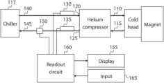
- FIG. 1is a block diagram of system for monitoring a cooling system, according to an embodiment of the present disclosure
- FIG. 2 Ais a graph of temperatures, according to an embodiment of the present disclosure.
- FIG. 2 Bis a graph of temperatures, according to an embodiment of the present disclosure.
- FIG. 2 Cis a graph of temperatures, according to an embodiment of the present disclosure.
- FIG. 2 Dis a graph of temperatures, according to an embodiment of the present disclosure.
- FIG. 3is a block diagram of system for monitoring a cooling system, according to an embodiment of the present disclosure.
- a cooling system for a magnetin an MRI system includes a helium compressor that compresses and cools a mixture of helium gas and oil, and feeds it, through an outlet, or “helium outlet” 110 , to a cold head.
- the compressed heliumis caused to do work as it expands within a set of displacers; as a result of doing this work the helium cools further, and is used to cool the magnet to cryogenic temperatures sufficiently low to keep the conductors of the magnet superconducting.
- the helium and oil mixturereturns, through an inlet, or “helium inlet” 115 , of the helium compressor, to the helium compressor.
- the helium compressoris in turn cooled by coolant that it receives from a coolant source, such as a chiller 117 , through an inlet coolant line 140 , at a coolant inlet 120 , and which after passing through the helium compressor leaves the helium compressor through an outlet coolant line 145 , at a coolant outlet 125 .
- An inlet temperature sensor 130may be secured to the inlet coolant line, and an outlet temperature sensor 135 may be secured to the outlet coolant line, the two sensors being part of a monitoring system for the cooling system, as discussed in further detail below.
- the inlet coolant line 140may be insulated, and carries chilled coolant from the chiller 117 to the helium compressor.
- the outlet coolant line 145may also be insulated, and carries return coolant from the helium compressor to the chiller 117 .
- the subsystem being cooled by the coolantmay be referred to as the “heat exchange process”.
- a “heat exchange process”is any heat source that may be connected to, and cooled by, a coolant source. Some embodiments may be used with other types of heat exchange processes, e.g., linear accelerators or CAT scan machines.
- the coolant sourceis not a dedicated chiller 117 as shown in FIG. 1 but is instead, for example, a large scale refrigeration system also supplying coolant to other heat exchange processes, such as other MRI systems, or an air conditioning system for a building housing an MRI machine.
- the heat exchange processmay require that the coolant temperature be within a certain range, and that the flow rate be in a certain range (which may depend on the temperature); the permissible combinations of flow rate and temperature may be called the “admissible range”.
- the inlet coolant temperaturemay be required to be between 4 degrees C. and 28 degrees C. and the coolant flow rate may be required to be less than 10 liters per minute, and greater than a linear function of temperature, the linear function having a value of 4 liters per minute at a temperature of 4 degrees C. and value of 7 liters per minute at a temperature of 28 degrees C.
- the chillermay include a reservoir of coolant (which may be a mixture of, e.g., 30% ethylene glycol and 70% deionized water), a refrigerator, and a pump that circulates coolant from a coolant inlet of the chiller, through the reservoir (which may also act as a heat exchanger of the refrigerator), through a coolant filter, through the helium compressor, and back to the chiller.
- a reservoir of coolantwhich may be a mixture of, e.g., 30% ethylene glycol and 70% deionized water
- a refrigeratorwhich may also act as a heat exchanger of the refrigerator
- a pumpthat circulates coolant from a coolant inlet of the chiller, through the reservoir (which may also act as a heat exchanger of the refrigerator), through a coolant filter, through the helium compressor, and back to the chiller.
- a temperature sensor(e.g., on the reservoir) may be used to control the refrigerator of the chiller, so that the chiller cycles on (e.g., the refrigerator of the chiller cycles on) when the temperature of the reservoir exceeds an upper threshold, and the chiller cycles off (e.g., the refrigerator of the chiller cycles off) when the temperature of the reservoir falls below a lower threshold.
- the chiller cycles one.g., the refrigerator of the chiller cycles on
- the chiller cycles offe.g., the refrigerator of the chiller cycles off
- the inlet coolant line 140may include a fluid-carrying line surrounded by a layer of insulation.
- the fluid carrying linemay be a hose, tube, or pipe (e.g., composed of metal or of reinforced (or unreinforced) polymer (e.g., plastic or an elastomer)).
- the insulationmay be flexible or rigid foam or fiber insulation.
- the inlet temperature sensor 130may be secured, inside the layer of insulation, e.g., with adhesive tape, to the fluid carrying line. A thermal compound or thermal pad may be used between the inlet temperature sensor 130 and the fluid carrying line to establish good thermal contact between them.
- the outlet coolant line 145may be of a similar construction, and the outlet temperature sensor 135 may be installed within it in an analogous fashion.
- the inlet temperature sensor 130 and the outlet temperature sensor 135are installed near the heat exchange process, e.g., within 10 inches or within 60 inches of the heat exchange process, for a poorly insulated line, or at a greater distance, e.g., up to 500 feet, for a well-insulated line, and they are installed such that the thermal conductivity of the thermally conductive path between the coolant and each temperature sensor is relatively high (e.g., greater than 0.01 W/K).
- the thermal conductivitymay be increased by securing the inlet temperature sensor 130 and the outlet temperature sensor 135 to a metal portion of the inlet coolant line 140 and the outlet coolant line 145 , respectively.
- This installation approachmay improve the quality of the temperature measurements, e.g., it may improve the signal to noise ratio for sensing, e.g., temperature fluctuations at the outlet of the heat exchange process.
- the outlet temperature sensor 135were instead installed at a location on the outlet coolant line 145 that is distant from the heat exchange process, and the outlet coolant line were poorly insulated, then the effect of temperature fluctuations at the outlet of the heat exchange process would be attenuated as a result of heat being conducted out of the outlet coolant line 145 into the air in the room, and it is possible that significant noise would be introduced as a result of fluctuations in room temperature.
- the combination of the thermal resistance of the conductive path and the heat capacity of the temperature sensormay act as a low-pass filter, suppressing relatively high-frequency signals such as those caused by the chiller cycling on and off.
- each of the inlet temperature sensor 130 and the outlet temperature sensor 135may be installed (e.g., on a metal portion of the respective coolant line, using a thermal compound, and without other thermally massive parts (such as a metal clamp) in contact with the temperature sensor) such that the thermal time constant, at the temperature sensor, for coolant temperature fluctuations, is less than e.g., 1 minute or 5 minutes (e.g., such that the thermal time constant is between 0.1 minutes and 100.0 minutes).
- Each temperature sensormay be, for example, a Dallas Semiconductor DS18B20 temperature sensor packaged in a waterproof (e.g., a substantially cylindrical stainless steel) housing.
- the analog signals from the temperature sensorsmay be amplified and filtered and periodically sampled and converted to digital form with an analog to digital converter.
- the interval between successive samplesmay be as short as the response time of the sensors, or considerably longer, corresponding for example to the shortest time scale on which significant temperature changes are expected to take place.
- the interval between successive samplesmay be between 0.1 second and 1000.0 seconds, and it may be, for example, 0.1 seconds, 1 second, 10 seconds, or 100 seconds.
- sensor assembliesincluding sensors and analog to digital converters, and producing digital (e.g., 1-wire) output signals (e.g., model OW-TEMP-S3-12 temperature probes, available from embeddeddatasystems.com) may be used.
- one or more flow meters 150may be included in the system, e.g., on the outlet coolant line 145 (as shown in FIG. 1 ) or on the inlet coolant line 140 , or in the heat exchange process, or in the cooler. Such a flow meter may be used to calculate (as the product of the temperature difference and the flow rate) the total rate at which heat is removed from the heat exchange process by the coolant.
- the flow meter 150may have a paddle-wheel sensor, an infrared sensor, a Doppler sensor, or a magnetic sensor, and it may be selected to be capable of measuring a flow rate of up to five gallons per minute, in a pipe with an inside diameter of about 3 ⁇ 8 inch.
- the digital datawhich may include two sequences (one for each of the two temperature sensors) of periodic temperature measurements, may then be stored for later analysis or sent in a stream to a user device such as a display.
- the datamay be displayed to the user as a graph with two traces, each trace showing the history of a respective one of the two temperatures. From such a graph a user may observe changes in the temperatures and, from them, assess the status of the magnet cooling system and diagnose potential problems.
- the temperature datamay be displayed in a “dashboard view” showing only, e.g., the numerical values of the most recent readings from the inlet temperature sensor 130 and the outlet temperature sensor 135 , or (i) the most recent reading from the inlet temperature sensor 130 and (ii) the difference between the most recent reading from the outlet temperature sensor 135 and the inlet temperature sensor 130 .
- Each value displayedin a graph, or as a numerical value, may be a linear combination of a temperature reading from the inlet temperature sensor 130 and a temperature reading from the outlet temperature sensor 135 .
- one such linear combinationmay be (as mentioned above) the difference between the most recent reading from the outlet temperature sensor 135 and the inlet temperature sensor 130 .
- linear combinationsinclude (i) the temperature reading from the inlet temperature sensor 130 and (ii) the temperature reading from the outlet temperature sensor 135 . If a flow meter 150 is present, the system may also display (as a numerical value or as a graph) the flow rate, or a quantity derived from the flow rate and the measured temperatures, such as the total rate at which heat is removed from the heat exchange process by the coolant.
- FIG. 2 Ais a graph of the temperature at the helium compressor coolant inlet (“Comp 1 _in”; the lower temperature history shown) and at the helium compressor coolant outlet (“Comp 1 _out”; the upper temperature history shown) during normal operation, in some embodiments.
- the two temperaturesmay, on average, each be relatively constant, and may decrease together when the refrigerator in the chiller 117 cycles on, and increase together when the refrigerator in the chiller 117 cycles off.
- the normal inlet temperaturemay be in the range of 40 degrees (Fahrenheit) to 82 degrees, and the normal temperature difference may be between 10 and 25 degrees.
- Each temperaturemay, in normal operation, fluctuate (as shown) by about 5 degrees (e.g., +/ ⁇ 2.5 degrees) as the refrigerator in the chiller 117 cycles on and off.
- a graph such as that of FIG. 2 Amay be displayed on a display 155 ( FIG. 1 ) by a suitable readout circuit 160 .
- the duty cyclein the graph of FIG. 2 A , is about 50% (the upward-sloping portions and downward-sloping portions being about equally steep), implying that about one half of the cooling capacity of the refrigerator of the chiller is being utilized. If the duty cycle increases, it may be an indication that the reserve cooling capacity of the refrigerator is decreasing. For example, if the temperature of the ambient air that the chiller uses for cooling increases, an increase in the duty cycle may be observed, as the rate at which the refrigerator is able to extract heat from the coolant is reduced, and the time required to cool the reservoir from the upper threshold to the lower threshold increases. As such, an observed increase in duty cycle may be used to infer a loss of cooling capacity reserve.
- a trend in the duty cyclemay be used to predict when the duty cycle will reach 100% and the chiller outlet temperature will continue to increase even when the chiller refrigerator cycles on.
- the ability to determine the chiller duty cycle in the coolant temperaturemay require a relatively good thermal contact between the temperature sensors and the coolant (so that the upward-sloping portions may be distinguishable from the downward-sloping portions in at least one of the temperature histories), because (as mentioned above) a relatively poor thermal contact may cause low-pass filtering of the temperature measurement, which may have the effect of smoothing the temperature traces (as may be seen in FIGS. 2 B- 2 D , discussed in further detail below).
- FIG. 2 Bshows the temperature history that may be observed if a power outage causes the helium compressor and the chiller to be shut off simultaneously (at about 14:30 in the graph of FIG. 2 B ).
- the coolant return line from the heat exchange processmay begin to cool, because the heat exchange process is no longer generating, heat, and the coolant inlet to the heat exchange process may begin to warm, because the chiller is no longer supplying chilled coolant.
- ambient temperaturee.g., room temperature
- FIG. 2 Cshows the temperature history that may be observed if the refrigerator of the chiller shuts down (while the pump continues to operate) and the helium compressor shuts down at nearly the same time (e.g., at about 8:10) when the compressor detects that the temperature at the coolant inlet has fallen outside of the admissible range.
- normal operationis then restored at about 9:00.
- FIG. 2 Dshows the temperature history that may be observed if the helium compressor shuts down, e.g., as a result of a reduction in coolant flow, and a resultant increase in the outlet coolant temperature of the helium compressor (e.g., at about 11:25, in the graph shown).
- the coolant inlet temperatureis substantially unchanged, being controlled by the internal temperature controller of the chiller, while the temperature difference drops to nearly zero, as the helium compressor ceases to heat the coolant flowing through it.
- the periodic temperature fluctuations caused by the chiller cycling on and offare not visible in FIGS. 2 B- 2 D , possibly because the thermal resistance between the coolant and each temperature sensor, combined with the thermal inertia of the temperature sensor and its surroundings, act as a thermal low-pass filter.
- a reduction in the coolant flow ratemay cause the temperature difference to increase, as the substantially constant heat load from the helium compressor is carried away by a reduced flow of fluid.
- the reduction in coolant flow ratemay in turn be a symptom of several potential causes, including a clogged filter or heat exchanger in the chiller, a clogged heat exchanger in the helium compressor, a pinched hose between the chiller and the helium compressor, the chiller being low on coolant (which may cause the chiller to shut down, if it is configured to shut down when the level in the reservoir drops below a threshold level, or which may cause the chiller pump to lose efficiency as it pumps a mixture of coolant and air), or a chiller pump failure.
- An improper coolant solutionmay fail to adequately inhibit bacterial growth and may result in clogging of the filter or heat exchanger in the chiller, or clogging of any other element having one or more small passages carrying coolant. As such, an increasing temperature difference may be an indication of reduced coolant flow, caused, for example, by clogging.
- Excessive coolant flowmay cause the temperature difference to decrease.
- Excessive coolant flowmay be a symptom of a flow regulator failure in a system using an oversized chiller (e.g., using a facility-scale cooling plant, as mentioned above).
- Excess coolant flowmay reduce the efficiency of the helium compressor.
- a failure of the refrigerator in the chillermay cause both temperatures to increase together, initially, until the helium compressor inlet temperature increases sufficiently to cause the helium compressor to shut down.
- the flow meterwhich may be used, as mentioned above, to calculate the total rate at which heat is removed from the heat load by the coolant, may be helpful in detecting such a condition.
- a temperature measuring system as described hereinmay be used to diagnose potential problems in a cooling system, and to derive information about the operating conditions of such a cooling system.
- the system and method for monitoring a cooling systemmay include a battery-based power supply (or “uninterruptible power supply” (UPS)) 305 for the readout circuit 160 (or “remote diagnostic unit” (RDU)), as shown in FIG. 3 .
- UPSuninterruptible power supply
- RDUremote diagnostic unit
- a mobile MRI systemis installed on a trailer with a 480 V generator for powering the helium compressor and the chiller.
- the trailerWhen the MRI system is operating, the trailer may be connected to shore power, which may include 480 V power for the helium compressor and the chiller, and 110 V power for powering the readout circuit 160 .
- the 480 V generatormay run when the trailer is in transit, so that the liquid helium bath may be maintained. Power at 110 V, for use by the readout circuit 160 , may not be available from the 480 V generator on the trailer.
- the battery-based power supplymay be charged while the system is connected to shore power, and battery power may then be used to power the readout circuit 160 during transit.
- Communications to a monitoring centermay be maintained by a via cellular modem in (or connected to) the readout circuit 160 , and via the Internet, to which the cellular modem may provide a connection.
- the readout circuit 160may include a processing circuit configured to receive temperature readings from the temperature sensors (and, in some embodiments, from other sensors such as the monitor 315 ) and display the results (as mentioned above) on a display.
- the displaymay be, for example, a display on a web client computer connected through the internet to the processing circuit receiving the temperature readings.
- One or more user input devices 165e.g., a keyboard and a mouse
- the readout circuit 160may be a motherboard, or a desktop or laptop computer with suitable interface cards for connecting to the temperature sensors, for example.
- processing circuitis used herein to mean any combination of hardware, firmware, and software, employed to process data or digital signals.
- Processing circuit hardwaremay include, for example, application specific integrated circuits (ASICs), general purpose or special purpose central processing units (CPUs), digital signal processors (DSPs), graphics processing units (GPUs), and programmable logic devices such as field programmable gate arrays (FPGAs).
- ASICsapplication specific integrated circuits
- CPUsgeneral purpose or special purpose central processing units
- DSPsdigital signal processors
- GPUsgraphics processing units
- FPGAsprogrammable logic devices
- each functionis performed either by hardware configured, i.e., hard-wired, to perform that function, or by more general purpose hardware, such as a CPU, configured to execute instructions stored in a non-transitory storage medium.
- a processing circuitmay be fabricated on a single printed circuit board (PCB) or distributed over several interconnected PCBs.
- a processing circuitmay contain other processing circuits; for example a processing circuit may include two processing circuits, an FPGA and a CPU, interconnected on a PCB.
- any numerical range recited hereinis intended to include all sub-ranges of the same numerical precision subsumed within the recited range.
- a range of “between 1.0 and 10.0”is intended to include all subranges between (and including) the recited minimum value of 1.0 and the recited maximum value of 10.0, that is, having a minimum value equal to or greater than 1.0 and a maximum value equal to or less than 10.0, such as, for example, 2.4 to 7.6.
- Any maximum numerical limitation recited hereinis intended to include all lower numerical limitations subsumed therein and any minimum numerical limitation recited in this specification is intended to include all higher numerical limitations subsumed therein.
Landscapes
- Physics & Mathematics (AREA)
- General Physics & Mathematics (AREA)
- Health & Medical Sciences (AREA)
- Condensed Matter Physics & Semiconductors (AREA)
- Life Sciences & Earth Sciences (AREA)
- Engineering & Computer Science (AREA)
- Nuclear Medicine, Radiotherapy & Molecular Imaging (AREA)
- Combustion & Propulsion (AREA)
- Chemical & Material Sciences (AREA)
- Electromagnetism (AREA)
- Biomedical Technology (AREA)
- Heart & Thoracic Surgery (AREA)
- Medical Informatics (AREA)
- Molecular Biology (AREA)
- Surgery (AREA)
- Animal Behavior & Ethology (AREA)
- General Health & Medical Sciences (AREA)
- Public Health (AREA)
- Veterinary Medicine (AREA)
- Pathology (AREA)
- Biophysics (AREA)
- Radiology & Medical Imaging (AREA)
- High Energy & Nuclear Physics (AREA)
Abstract
Description
Claims (15)
Priority Applications (1)
| Application Number | Priority Date | Filing Date | Title |
|---|---|---|---|
| US16/428,825US11703393B2 (en) | 2018-06-01 | 2019-05-31 | System and method for monitoring cooling system |
Applications Claiming Priority (2)
| Application Number | Priority Date | Filing Date | Title |
|---|---|---|---|
| US201862679701P | 2018-06-01 | 2018-06-01 | |
| US16/428,825US11703393B2 (en) | 2018-06-01 | 2019-05-31 | System and method for monitoring cooling system |
Publications (2)
| Publication Number | Publication Date |
|---|---|
| US20190368945A1 US20190368945A1 (en) | 2019-12-05 |
| US11703393B2true US11703393B2 (en) | 2023-07-18 |
Family
ID=68694609
Family Applications (1)
| Application Number | Title | Priority Date | Filing Date |
|---|---|---|---|
| US16/428,825Active2041-09-04US11703393B2 (en) | 2018-06-01 | 2019-05-31 | System and method for monitoring cooling system |
Country Status (1)
| Country | Link |
|---|---|
| US (1) | US11703393B2 (en) |
Cited By (1)
| Publication number | Priority date | Publication date | Assignee | Title |
|---|---|---|---|---|
| US20220404445A1 (en)* | 2021-06-22 | 2022-12-22 | Bruker Biospin Gmbh | Autonomous cooling of a superconductive dry-cooled mr magnetic coil system |
Families Citing this family (1)
| Publication number | Priority date | Publication date | Assignee | Title |
|---|---|---|---|---|
| RU206341U1 (en)* | 2021-04-22 | 2021-09-06 | федеральное государственное бюджетное образовательное учреждение высшего образования "Нижегородский государственный технический университет им. Р.Е. Алексеева" (НГТУ) | Test bench for pumping and static heeling of hydraulic circuits with natural circulation |
Citations (50)
| Publication number | Priority date | Publication date | Assignee | Title |
|---|---|---|---|---|
| US5960636A (en)* | 1997-11-14 | 1999-10-05 | Air Products And Chemicals, Inc. | Method and apparatus for precooling a mass prior to immersion in a cryogenic liquid |
| US6252405B1 (en)* | 1999-11-15 | 2001-06-26 | General Electric Company | Temperature compensated NMR magnet and method of operation therefor |
| US6354087B1 (en)* | 1998-05-22 | 2002-03-12 | Sumitomo Electric Industries, Ltd | Method and apparatus for cooling superconductor |
| US6516282B2 (en)* | 2001-04-19 | 2003-02-04 | Ge Medical Systems Global Technology Company | Predictive thermal control used with a vacuum enclosed coil assembly of a magnetic resonance imaging device |
| US6525537B2 (en)* | 1999-12-22 | 2003-02-25 | Siemens Aktiengesellschaft | Magnetic resonance apparatus having a single-circuit cooling circulation system |
| US20030052681A1 (en)* | 2001-09-14 | 2003-03-20 | Kazuhiro Kono | Failure prediction apparatus for superconductive magnet and magnetic resonance imaging system |
| US20030140638A1 (en)* | 2001-08-22 | 2003-07-31 | Delaware Capital Formation, Inc. | Refrigeration system |
| US6655835B2 (en)* | 1999-12-21 | 2003-12-02 | Schweitzer Engineering Laboratories Inc. | Setting-free resistive temperature device (RTD) measuring module |
| US20040017195A1 (en)* | 2002-05-07 | 2004-01-29 | Kabushiki Kaisha Toshiba | MRI apparatus and method for calculating predicted and/or actual net accumulated gradient coil heat and/or temperature |
| US20050035764A1 (en)* | 2003-08-14 | 2005-02-17 | Anthony Mantone | Method and apparatus for directly cooling hollow conductor wound transverse gradient coil boards |
| US20050126276A1 (en)* | 2003-12-16 | 2005-06-16 | International Business Machines Corporation | Method, system and program product for monitoring rate of volume change of coolant within a cooling system |
| US6909283B2 (en)* | 2001-04-12 | 2005-06-21 | General Electric Company | Method and system to regulate cooling of a medical imaging device |
| US20070125102A1 (en)* | 2005-12-05 | 2007-06-07 | Carrier Corporation | Detection of refrigerant charge adequacy based on multiple temperature measurements |
| US7297907B2 (en) | 2005-12-08 | 2007-11-20 | Uri Rapoport | Means and method of maintaining a constant temperature in the magnetic assembly of a magnetic resonance device |
| US7301343B1 (en)* | 2006-12-18 | 2007-11-27 | General Electric Co. | System, method and apparatus for controlling the temperature of a MRI magnet warm bore |
| US7304477B2 (en)* | 2003-11-24 | 2007-12-04 | Koninklijke Philips Electronics N.V. | MRI apparatus with means for noise reduction |
| US20090015258A1 (en)* | 2007-07-12 | 2009-01-15 | Seiji Nozaki | Magnetic resonance imaging apparatus and magnetic resonance imaging method |
| US7511501B2 (en)* | 2007-05-11 | 2009-03-31 | General Electric Company | Systems and apparatus for monitoring internal temperature of a gradient coil |
| US20090123139A1 (en)* | 2007-11-09 | 2009-05-14 | General Electric Company | System, method and apparatus for controlling drift of a main magnetic field in an mri system |
| US20090128269A1 (en)* | 2007-11-15 | 2009-05-21 | General Electric Company | Cooling system and apparatus for controlling drift of a main magnetic field in an mri system |
| US7538551B2 (en)* | 2005-09-16 | 2009-05-26 | Siemens Aktiengesellschaft | Magnetic resonance gradient coil system having a liquid electrical conductor |
| US20100016168A1 (en)* | 2005-11-01 | 2010-01-21 | Andrew Farquhar Atkins | Apparatus and method for transporting cryogenically cooled goods or equipment |
| US20100188083A1 (en)* | 2009-01-24 | 2010-07-29 | Kai Cao | Magnetic resonance imaging system and method for stabilizing the temperature of the main magnet therein |
| US20100315086A1 (en)* | 2008-03-13 | 2010-12-16 | Yoshitomo Sakakura | Magnetic resonance imaging apparatus and chiller |
| US7994787B2 (en)* | 2006-07-12 | 2011-08-09 | Hitachi Medical Corporation | Superconducting magnet, magnetic resonance imaging apparatus, and method of calculating coolability of cryo-cooler |
| US8102178B2 (en)* | 2008-08-04 | 2012-01-24 | Siemens Aktiengesellschaft | Detector arrangement |
| US8305079B2 (en)* | 2008-10-03 | 2012-11-06 | Kabushiki Kaisha Toshiba | Magnetic resonance imaging apparatus and gradient coil cooling control method |
| US20130287063A1 (en)* | 2004-08-11 | 2013-10-31 | Emerson Climate Technologies, Inc. | Method and Apparatus for Monitoring A Refrigeration-Cycle System |
| US8593145B2 (en)* | 2007-12-11 | 2013-11-26 | Koninklijke Philips N.V. | Magnetic resonance system with cooling system and monitoring of helium pressure |
| US8602049B2 (en)* | 2010-06-16 | 2013-12-10 | Linde Aktiengesellschaft | Methods and apparatus for filling superconductive magnets |
| US20140009151A1 (en)* | 2011-03-24 | 2014-01-09 | Koninklijke Philips N.V. | Reduction of peak electrical power consumption in magnetic resonance imaging systems |
| US8643370B2 (en)* | 2010-01-14 | 2014-02-04 | Siemens Aktiengellschaft | Flow sensor for cooling water in a gradient coil |
| US8680862B2 (en)* | 2009-05-29 | 2014-03-25 | Kabushiki Kaisha Toshiba | Magnetic resonance imaging apparatus |
| US20150042339A1 (en)* | 2013-08-12 | 2015-02-12 | Razvan Lazar | Thermostabilization of antenna array for magnetic resonance tomography |
| US20150047377A1 (en)* | 2013-08-19 | 2015-02-19 | Sumitomo Heavy Industries, Ltd. | Monitoring method and cooling system |
| US20150153428A1 (en)* | 2013-11-29 | 2015-06-04 | Ping Chen | Cooling Device and Method for Magnetic Resonance Imaging System |
| US20160291104A1 (en)* | 2013-11-29 | 2016-10-06 | Hitachi, Ltd. | Magnetic resonance imaging apparatus |
| US20170045590A1 (en)* | 2015-08-10 | 2017-02-16 | Toshiba Medical Systems Corporation | Magnetic resonance imaging apparatus and magnetic resonance imaging method |
| US20170082708A1 (en)* | 2014-11-04 | 2017-03-23 | Shanghai United Imaging Healthcare Co., Ltd. | Displacer in magnetic resonance imaging system |
| US20170139023A1 (en)* | 2015-11-13 | 2017-05-18 | Toshiba Medical Systems Corporation | Magnetic-resonance imaging apparatus |
| US9810754B2 (en)* | 2012-06-01 | 2017-11-07 | Toshiba Medical Systems Corporation | Cooling device for sub-MRI units and MRI apparatus |
| US20180035957A1 (en)* | 2016-01-29 | 2018-02-08 | Shanghai United Imaging Healthcare Co., Ltd. | Method and apparatus for temperature control in a pet detector |
| US20180045796A1 (en)* | 2016-08-09 | 2018-02-15 | Bruker Biospin Ag | Introducing an nmr apparatus comprising cooled probe components via a vacuum lock |
| US20180321344A1 (en)* | 2017-05-04 | 2018-11-08 | Siemens Healthcare Gmbh | Method, device and magnetic resonance apparatus for temperature regulation of a magnetizable environment of a gradient coil |
| US20190011511A1 (en)* | 2015-10-16 | 2019-01-10 | Synaptive Medical (Barbados) Inc. | Magnetic Resonance Imaging System Capable of Rapid Field Ramping |
| US20190072624A1 (en)* | 2017-09-06 | 2019-03-07 | Siemens Healthcare Gmbh | Method and magnetic resonance apparatus for monitoring a cooling system of the magnetic resonance apparatus |
| US20190086276A1 (en)* | 2017-09-19 | 2019-03-21 | Lennox Industries Inc. | Method and apparatus for identifying erroneous discharge air temperature (dat) sensor installation |
| US10267876B2 (en)* | 2014-09-30 | 2019-04-23 | Siemens Aktiengesellschaft | Magnetic resonance apparatus with a cooling apparatus |
| US20190310333A1 (en)* | 2016-06-28 | 2019-10-10 | Koninklijke Philips N.V. | Magnetic resonance imaging with improved thermal performance |
| US20190311332A1 (en)* | 2017-05-25 | 2019-10-10 | Johnson Controls Technology Company | Model predictive maintenance system with incentive incorporation |
- 2019
- 2019-05-31USUS16/428,825patent/US11703393B2/enactiveActive
Patent Citations (57)
| Publication number | Priority date | Publication date | Assignee | Title |
|---|---|---|---|---|
| US5960636A (en)* | 1997-11-14 | 1999-10-05 | Air Products And Chemicals, Inc. | Method and apparatus for precooling a mass prior to immersion in a cryogenic liquid |
| US6354087B1 (en)* | 1998-05-22 | 2002-03-12 | Sumitomo Electric Industries, Ltd | Method and apparatus for cooling superconductor |
| US6252405B1 (en)* | 1999-11-15 | 2001-06-26 | General Electric Company | Temperature compensated NMR magnet and method of operation therefor |
| US6655835B2 (en)* | 1999-12-21 | 2003-12-02 | Schweitzer Engineering Laboratories Inc. | Setting-free resistive temperature device (RTD) measuring module |
| US6525537B2 (en)* | 1999-12-22 | 2003-02-25 | Siemens Aktiengesellschaft | Magnetic resonance apparatus having a single-circuit cooling circulation system |
| US6909283B2 (en)* | 2001-04-12 | 2005-06-21 | General Electric Company | Method and system to regulate cooling of a medical imaging device |
| US6992483B1 (en)* | 2001-04-12 | 2006-01-31 | General Electric Company | Method and system to regulate cooling of a medical imaging device |
| US6516282B2 (en)* | 2001-04-19 | 2003-02-04 | Ge Medical Systems Global Technology Company | Predictive thermal control used with a vacuum enclosed coil assembly of a magnetic resonance imaging device |
| US20030140638A1 (en)* | 2001-08-22 | 2003-07-31 | Delaware Capital Formation, Inc. | Refrigeration system |
| US20030052681A1 (en)* | 2001-09-14 | 2003-03-20 | Kazuhiro Kono | Failure prediction apparatus for superconductive magnet and magnetic resonance imaging system |
| US20040017195A1 (en)* | 2002-05-07 | 2004-01-29 | Kabushiki Kaisha Toshiba | MRI apparatus and method for calculating predicted and/or actual net accumulated gradient coil heat and/or temperature |
| US20050035764A1 (en)* | 2003-08-14 | 2005-02-17 | Anthony Mantone | Method and apparatus for directly cooling hollow conductor wound transverse gradient coil boards |
| US7304477B2 (en)* | 2003-11-24 | 2007-12-04 | Koninklijke Philips Electronics N.V. | MRI apparatus with means for noise reduction |
| US20050126276A1 (en)* | 2003-12-16 | 2005-06-16 | International Business Machines Corporation | Method, system and program product for monitoring rate of volume change of coolant within a cooling system |
| US20130287063A1 (en)* | 2004-08-11 | 2013-10-31 | Emerson Climate Technologies, Inc. | Method and Apparatus for Monitoring A Refrigeration-Cycle System |
| US7538551B2 (en)* | 2005-09-16 | 2009-05-26 | Siemens Aktiengesellschaft | Magnetic resonance gradient coil system having a liquid electrical conductor |
| US20100016168A1 (en)* | 2005-11-01 | 2010-01-21 | Andrew Farquhar Atkins | Apparatus and method for transporting cryogenically cooled goods or equipment |
| US20070125102A1 (en)* | 2005-12-05 | 2007-06-07 | Carrier Corporation | Detection of refrigerant charge adequacy based on multiple temperature measurements |
| US7297907B2 (en) | 2005-12-08 | 2007-11-20 | Uri Rapoport | Means and method of maintaining a constant temperature in the magnetic assembly of a magnetic resonance device |
| US7994787B2 (en)* | 2006-07-12 | 2011-08-09 | Hitachi Medical Corporation | Superconducting magnet, magnetic resonance imaging apparatus, and method of calculating coolability of cryo-cooler |
| US7301343B1 (en)* | 2006-12-18 | 2007-11-27 | General Electric Co. | System, method and apparatus for controlling the temperature of a MRI magnet warm bore |
| US7511501B2 (en)* | 2007-05-11 | 2009-03-31 | General Electric Company | Systems and apparatus for monitoring internal temperature of a gradient coil |
| US20090015258A1 (en)* | 2007-07-12 | 2009-01-15 | Seiji Nozaki | Magnetic resonance imaging apparatus and magnetic resonance imaging method |
| US7602185B2 (en)* | 2007-07-12 | 2009-10-13 | Kabushiki Kaisha Toshiba | Magnetic resonance imaging apparatus and magnetic resonance imaging method |
| US20090123139A1 (en)* | 2007-11-09 | 2009-05-14 | General Electric Company | System, method and apparatus for controlling drift of a main magnetic field in an mri system |
| US20090128269A1 (en)* | 2007-11-15 | 2009-05-21 | General Electric Company | Cooling system and apparatus for controlling drift of a main magnetic field in an mri system |
| US7868617B2 (en)* | 2007-11-15 | 2011-01-11 | General Electric Co. | Cooling system and apparatus for controlling drift of a main magnetic field in an MRI system |
| US8593145B2 (en)* | 2007-12-11 | 2013-11-26 | Koninklijke Philips N.V. | Magnetic resonance system with cooling system and monitoring of helium pressure |
| US8188741B2 (en)* | 2008-03-13 | 2012-05-29 | Kabushiki Kaisha Toshiba | Magnetic resonance imaging apparatus and chiller |
| US20100315086A1 (en)* | 2008-03-13 | 2010-12-16 | Yoshitomo Sakakura | Magnetic resonance imaging apparatus and chiller |
| US8102178B2 (en)* | 2008-08-04 | 2012-01-24 | Siemens Aktiengesellschaft | Detector arrangement |
| US8305079B2 (en)* | 2008-10-03 | 2012-11-06 | Kabushiki Kaisha Toshiba | Magnetic resonance imaging apparatus and gradient coil cooling control method |
| US8564292B2 (en)* | 2008-10-03 | 2013-10-22 | Kabushiki Kaisha Toshiba | Magnetic resonance imaging apparatus and gradient coil cooling control method |
| US20100188083A1 (en)* | 2009-01-24 | 2010-07-29 | Kai Cao | Magnetic resonance imaging system and method for stabilizing the temperature of the main magnet therein |
| US8680862B2 (en)* | 2009-05-29 | 2014-03-25 | Kabushiki Kaisha Toshiba | Magnetic resonance imaging apparatus |
| US8643370B2 (en)* | 2010-01-14 | 2014-02-04 | Siemens Aktiengellschaft | Flow sensor for cooling water in a gradient coil |
| US20140053576A1 (en)* | 2010-06-16 | 2014-02-27 | Niels LOSE | Methods and apparatus for filling superconductive magnets |
| US8602049B2 (en)* | 2010-06-16 | 2013-12-10 | Linde Aktiengesellschaft | Methods and apparatus for filling superconductive magnets |
| US20140009151A1 (en)* | 2011-03-24 | 2014-01-09 | Koninklijke Philips N.V. | Reduction of peak electrical power consumption in magnetic resonance imaging systems |
| US9810754B2 (en)* | 2012-06-01 | 2017-11-07 | Toshiba Medical Systems Corporation | Cooling device for sub-MRI units and MRI apparatus |
| US20150042339A1 (en)* | 2013-08-12 | 2015-02-12 | Razvan Lazar | Thermostabilization of antenna array for magnetic resonance tomography |
| US10047977B2 (en)* | 2013-08-19 | 2018-08-14 | Sumitomo Heavy Industries, Ltd. | Monitoring method and cooling system |
| US20150047377A1 (en)* | 2013-08-19 | 2015-02-19 | Sumitomo Heavy Industries, Ltd. | Monitoring method and cooling system |
| US20150153428A1 (en)* | 2013-11-29 | 2015-06-04 | Ping Chen | Cooling Device and Method for Magnetic Resonance Imaging System |
| US20160291104A1 (en)* | 2013-11-29 | 2016-10-06 | Hitachi, Ltd. | Magnetic resonance imaging apparatus |
| US10267876B2 (en)* | 2014-09-30 | 2019-04-23 | Siemens Aktiengesellschaft | Magnetic resonance apparatus with a cooling apparatus |
| US20170082708A1 (en)* | 2014-11-04 | 2017-03-23 | Shanghai United Imaging Healthcare Co., Ltd. | Displacer in magnetic resonance imaging system |
| US20170045590A1 (en)* | 2015-08-10 | 2017-02-16 | Toshiba Medical Systems Corporation | Magnetic resonance imaging apparatus and magnetic resonance imaging method |
| US20190011511A1 (en)* | 2015-10-16 | 2019-01-10 | Synaptive Medical (Barbados) Inc. | Magnetic Resonance Imaging System Capable of Rapid Field Ramping |
| US20170139023A1 (en)* | 2015-11-13 | 2017-05-18 | Toshiba Medical Systems Corporation | Magnetic-resonance imaging apparatus |
| US20180035957A1 (en)* | 2016-01-29 | 2018-02-08 | Shanghai United Imaging Healthcare Co., Ltd. | Method and apparatus for temperature control in a pet detector |
| US20190310333A1 (en)* | 2016-06-28 | 2019-10-10 | Koninklijke Philips N.V. | Magnetic resonance imaging with improved thermal performance |
| US20180045796A1 (en)* | 2016-08-09 | 2018-02-15 | Bruker Biospin Ag | Introducing an nmr apparatus comprising cooled probe components via a vacuum lock |
| US20180321344A1 (en)* | 2017-05-04 | 2018-11-08 | Siemens Healthcare Gmbh | Method, device and magnetic resonance apparatus for temperature regulation of a magnetizable environment of a gradient coil |
| US20190311332A1 (en)* | 2017-05-25 | 2019-10-10 | Johnson Controls Technology Company | Model predictive maintenance system with incentive incorporation |
| US20190072624A1 (en)* | 2017-09-06 | 2019-03-07 | Siemens Healthcare Gmbh | Method and magnetic resonance apparatus for monitoring a cooling system of the magnetic resonance apparatus |
| US20190086276A1 (en)* | 2017-09-19 | 2019-03-21 | Lennox Industries Inc. | Method and apparatus for identifying erroneous discharge air temperature (dat) sensor installation |
Cited By (2)
| Publication number | Priority date | Publication date | Assignee | Title |
|---|---|---|---|---|
| US20220404445A1 (en)* | 2021-06-22 | 2022-12-22 | Bruker Biospin Gmbh | Autonomous cooling of a superconductive dry-cooled mr magnetic coil system |
| US12055608B2 (en)* | 2021-06-22 | 2024-08-06 | Bruker Biospin Gmbh | Autonomous cooling of a superconductive dry-cooled MR magnetic coil system |
Also Published As
| Publication number | Publication date |
|---|---|
| US20190368945A1 (en) | 2019-12-05 |
Similar Documents
| Publication | Publication Date | Title |
|---|---|---|
| US7000467B2 (en) | Method, system and program product for monitoring rate of volume change of coolant within a cooling system | |
| TWI601923B (en) | Monitoring methods and cooling system | |
| US11703393B2 (en) | System and method for monitoring cooling system | |
| US20050126747A1 (en) | Method, system and program product for automatically checking coolant loops of a cooling system for a computing environment | |
| US20090210199A1 (en) | Superconducting magnet, magnetic resonance imaging apparatus, and method of calculating coolability of cryo-cooler | |
| TW201716761A (en) | Refrigerant leakage sensing system in refrigerating cycle | |
| CN216819866U (en) | Freezer monitored control system | |
| CN108758979A (en) | Air-conditioning system and its energy efficiency analysis method for air, device and storage medium | |
| CN1942979B (en) | Circulation cooling system for cryogenic cable | |
| Wang et al. | Universal Direct-to-Chip Cold Plates for Single-and Two-Phase Cooling | |
| CN105004399A (en) | Specific heat liquid level meter | |
| CN115355449B (en) | A pipeline flow monitoring method, electromagnetic flowmeter and system | |
| CN217276921U (en) | Refrigeration performance test system suitable for semiconductor water-cooling type refrigeration module | |
| CN206724535U (en) | A kind of monitoring system of large-scale refrigeration plant | |
| US11415156B2 (en) | Method for monitoring the condition of a hydraulic system of a metal forming plant and condition-monitoring device | |
| JP2006222417A (en) | Superconducting magnet device monitoring system, superconducting magnet device monitoring method, and MRI apparatus | |
| JP3083930B2 (en) | Failure diagnosis system for absorption refrigerator | |
| CN221666361U (en) | Ice water machine and cooling system | |
| CN120804766A (en) | Monitoring system and method for immersed liquid cooling server system | |
| CN204854882U (en) | Specific heat level gauge | |
| CN215176347U (en) | Nuclear magnetic resonance system cooling device | |
| JPH07234048A (en) | Trouble diagnostic system for absorption type water cooling and heating machine | |
| CN105278577A (en) | Superheat degree detection method in two-phase flow cooling system | |
| CN218469909U (en) | Locomotive converter test system | |
| CN113971101B (en) | Method, device, storage medium and system for diagnosing temperature faults of server |
Legal Events
| Date | Code | Title | Description |
|---|---|---|---|
| FEPP | Fee payment procedure | Free format text:ENTITY STATUS SET TO UNDISCOUNTED (ORIGINAL EVENT CODE: BIG.); ENTITY STATUS OF PATENT OWNER: SMALL ENTITY | |
| FEPP | Fee payment procedure | Free format text:ENTITY STATUS SET TO SMALL (ORIGINAL EVENT CODE: SMAL); ENTITY STATUS OF PATENT OWNER: SMALL ENTITY | |
| STPP | Information on status: patent application and granting procedure in general | Free format text:DOCKETED NEW CASE - READY FOR EXAMINATION | |
| STPP | Information on status: patent application and granting procedure in general | Free format text:NON FINAL ACTION MAILED | |
| STPP | Information on status: patent application and granting procedure in general | Free format text:RESPONSE TO NON-FINAL OFFICE ACTION ENTERED AND FORWARDED TO EXAMINER | |
| STPP | Information on status: patent application and granting procedure in general | Free format text:FINAL REJECTION MAILED | |
| STPP | Information on status: patent application and granting procedure in general | Free format text:RESPONSE AFTER FINAL ACTION FORWARDED TO EXAMINER | |
| STPP | Information on status: patent application and granting procedure in general | Free format text:NOTICE OF ALLOWANCE MAILED -- APPLICATION RECEIVED IN OFFICE OF PUBLICATIONS | |
| AS | Assignment | Owner name:SOUTHWEST MEDICAL RESOURCES, INC., CALIFORNIA Free format text:ASSIGNMENT OF ASSIGNORS INTEREST;ASSIGNOR:MCCORMACK, MICHAEL SHANE;REEL/FRAME:063678/0668 Effective date:20230516 | |
| STPP | Information on status: patent application and granting procedure in general | Free format text:PUBLICATIONS -- ISSUE FEE PAYMENT VERIFIED | |
| STCF | Information on status: patent grant | Free format text:PATENTED CASE | |
| STCF | Information on status: patent grant | Free format text:PATENTED CASE |