US11701556B2 - Golf club head with external and internal ribs - Google Patents
Golf club head with external and internal ribsDownload PDFInfo
- Publication number
- US11701556B2 US11701556B2US16/460,114US201916460114AUS11701556B2US 11701556 B2US11701556 B2US 11701556B2US 201916460114 AUS201916460114 AUS 201916460114AUS 11701556 B2US11701556 B2US 11701556B2
- Authority
- US
- United States
- Prior art keywords
- club head
- external
- golf club
- rib
- top portion
- Prior art date
- Legal status (The legal status is an assumption and is not a legal conclusion. Google has not performed a legal analysis and makes no representation as to the accuracy of the status listed.)
- Active
Links
Images


Classifications
- A—HUMAN NECESSITIES
- A63—SPORTS; GAMES; AMUSEMENTS
- A63B—APPARATUS FOR PHYSICAL TRAINING, GYMNASTICS, SWIMMING, CLIMBING, OR FENCING; BALL GAMES; TRAINING EQUIPMENT
- A63B53/00—Golf clubs
- A63B53/04—Heads
- A—HUMAN NECESSITIES
- A63—SPORTS; GAMES; AMUSEMENTS
- A63B—APPARATUS FOR PHYSICAL TRAINING, GYMNASTICS, SWIMMING, CLIMBING, OR FENCING; BALL GAMES; TRAINING EQUIPMENT
- A63B53/00—Golf clubs
- A63B53/04—Heads
- A63B53/0466—Heads wood-type
- A—HUMAN NECESSITIES
- A63—SPORTS; GAMES; AMUSEMENTS
- A63B—APPARATUS FOR PHYSICAL TRAINING, GYMNASTICS, SWIMMING, CLIMBING, OR FENCING; BALL GAMES; TRAINING EQUIPMENT
- A63B53/00—Golf clubs
- A63B53/04—Heads
- A63B53/0408—Heads characterised by specific dimensions, e.g. thickness
- A—HUMAN NECESSITIES
- A63—SPORTS; GAMES; AMUSEMENTS
- A63B—APPARATUS FOR PHYSICAL TRAINING, GYMNASTICS, SWIMMING, CLIMBING, OR FENCING; BALL GAMES; TRAINING EQUIPMENT
- A63B53/00—Golf clubs
- A63B53/04—Heads
- A63B53/0408—Heads characterised by specific dimensions, e.g. thickness
- A63B53/0412—Volume
- A—HUMAN NECESSITIES
- A63—SPORTS; GAMES; AMUSEMENTS
- A63B—APPARATUS FOR PHYSICAL TRAINING, GYMNASTICS, SWIMMING, CLIMBING, OR FENCING; BALL GAMES; TRAINING EQUIPMENT
- A63B53/00—Golf clubs
- A63B53/04—Heads
- A63B53/0437—Heads with special crown configurations
- A—HUMAN NECESSITIES
- A63—SPORTS; GAMES; AMUSEMENTS
- A63B—APPARATUS FOR PHYSICAL TRAINING, GYMNASTICS, SWIMMING, CLIMBING, OR FENCING; BALL GAMES; TRAINING EQUIPMENT
- A63B53/00—Golf clubs
- A63B53/04—Heads
- A63B53/045—Strengthening ribs
- A—HUMAN NECESSITIES
- A63—SPORTS; GAMES; AMUSEMENTS
- A63B—APPARATUS FOR PHYSICAL TRAINING, GYMNASTICS, SWIMMING, CLIMBING, OR FENCING; BALL GAMES; TRAINING EQUIPMENT
- A63B60/00—Details or accessories of golf clubs, bats, rackets or the like
- A63B60/002—Resonance frequency related characteristics
- A—HUMAN NECESSITIES
- A63—SPORTS; GAMES; AMUSEMENTS
- A63B—APPARATUS FOR PHYSICAL TRAINING, GYMNASTICS, SWIMMING, CLIMBING, OR FENCING; BALL GAMES; TRAINING EQUIPMENT
- A63B60/00—Details or accessories of golf clubs, bats, rackets or the like
- A63B60/52—Details or accessories of golf clubs, bats, rackets or the like with slits
Definitions
- This disclosurerelates generally to the field of golf clubs. More particularly, it relates to a hollow-type golf club head with external and internal ribs.
- Drivingis often considered to be one of the most difficult aspects of golf. Because of the length associated with a drive, relatively minor deviations in striking face orientation at impact can have a substantial impact on the effectiveness of the shot, e.g., whether it is in the fairway, rough, or even out of bounds.
- the driveris intended to be the longest club in a golfer's bag, it is also often another goal of manufacturers to increase the distance at which a ball struck by the driver will travel.
- One manner by which to do sois to lower the club head's center of gravity. This may increase dynamic loft, i.e., the loft of the club head delivered at impact, as well reduce spin, thereby potentially resulting in greater ball flight for certain golfers.
- a hollow-type golf club headmay thus, when oriented in a reference position, comprise: a striking wall; a sole portion; a top portion having an exterior surface and an interior surface; a hosel extending from the top portion and defining a hosel axis; a plurality of external ribs located on the exterior surface of the top portion, the plurality of external ribs each being generally elongate in a front-to-rear direction; and at least one internal rib located on the interior surface of the top portion and being generally elongate in the front-to-rear direction.
- the at least one internal ribmay be spaced from the plurality of external ribs by a distance D 1 no less than 2 mm as considered in top view of the club head.
- a hollow-type golf club head in accordance with one or more aspects of the present disclosuremay also, when oriented in a reference position, comprise: a striking wall; a sole portion; a top portion having an exterior surface and an interior surface; a hosel extending from the top portion and defining a hosel axis; a plurality of external ribs located on the exterior surface of the top portion, the plurality of external ribs each being generally elongate in a front-to-rear direction and spaced apart from each other by a distance D 2 that is no less than 8 mm; and at least one internal rib located on the interior surface of the top portion and being generally elongate in the front-to-rear direction.
- any disclosed rangeencompasses a disclosure of each and every sub-range thereof.
- the range of 1-5encompasses a disclosure of at least 1-2, 1-3, 1-4, 1-5, 2-3, 2-4, 2-5, 3-4, 3-5, and 4-5.
- the end points of any disclosed rangeencompass a disclosure of those exact end points as well as of values at approximately or at about those endpoints.
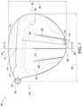
- FIG. 1shows a top plan view of a golf club head in accordance with one or more exemplary embodiments.
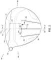
- FIG. 2shows another top plan view of the golf club head of FIG. 1 .
- FIG. 3shows a heel-side view of the golf club head of FIG. 1 .
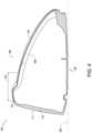
- FIG. 4shows a cross-section view of the golf club head of FIG. 1 .
- the club head 100may be a hollow-type club head.
- the club head 100may be a wood-type club head, and even more specifically, it may be a driver.
- the club head 100may generally be formed from metallic and/or nonmetallic materials, such as any one or a combination of aluminum, stainless steel, titanium, composites, polymeric materials, and any other suitable material.
- reference positiondenotes a club head position wherein a hosel has a hosel axis that is oriented at a lie angle ⁇ of 60° with respect to a horizontal virtual ground plane and lies in an imaginary vertical virtual hosel plane, which contains a virtual horizontal line parallel to the striking face.
- the club head 100may include a front portion 110 , which has a striking wall 111 including a striking face 112 for contacting a golf ball, and a rear portion 120 .
- the striking face 112may include a face center 114 , which is the point on the striking face 112 that is equidistant from the striking face periphery in both the horizontal direction and in the vertical direction, as set out in the United States Golf Association's Procedure for Measuring the Flexibility of a Golf Club Head (Revision 2.0, Mar. 25, 2005), in which “face center” is described as identifiable using a designated template for such purpose.
- the striking face 112may also include a central apex 116 .
- the club head 100may further include a toe portion 130 , a heel portion 140 , a sole portion 150 , and a top portion, or crown, 160 .
- the heel portion 140may include a hosel 142 configured to receive and secure a shaft (not shown) of the golf club.
- the hosel 142may have a hosel axis 144 .
- the club head 100may also include a center of gravity at a location 170 , which will be discussed in greater detail in the following.
- the top portion 160may also include a step-down portion 162 , in which the crown moves closer to the sole portion 150 .
- This step-down portion 162moves mass toward the sole portion 150 and increases structural integrity of the top portion 160 without significantly adding mass.
- the contour of the top portion 160may generally match that of the sole portion 150 .
- the contours of both the top portion and the sole portionpreferably have a high degree of visual symmetry and, as a result, mass symmetry.
- this matching contourhas various benefits. For example, similar air flow characteristics above and below the club head 100 may result in greater stability and rigidity of the club head through impact with the golf ball.
- x-, y-, and z-directionscorrespond to a virtual Cartesian coordinate system having its origin coincident with the center of gravity of the club head such that: an x-axis extends in the front-to-rear direction, a y-axis extends in the heel-to-toe direction, and a z-axis extends vertically.
- the club headmay be considered to have moments of inertia Ixx, Iyy, and Izz, corresponding to moments of inertia about respective axes x, y, and z.
- the club headmay also be considered to exhibit a conventional Inertia matrix which further includes products of inertia Ixy, Iyx, Ixz, Izx, Iyz, and Izy. These products of inertia are to a degree indicative of the mass symmetry about the plane to which they correspond.
- Ixymay be no greater than 540 g*cm 2 and more preferably no greater than 500 g*cm 2 .
- the top portion 160may also include at least one decal to add texture. Decals are often easier to apply than paint, where a reveal or recess in the club head exterior would be required for the paint.
- the top portion 160may yet also include at least one external rib 200 on its exterior surface. For example, it may include a central external rib 210 , a toe-side external rib 220 , and a heel-side external rib 230 .
- the top portion 160also may include at least one internal rib on its interior surface.
- One such internal rib 250is shown by way of phantom in FIG. 1 and in the cross-section of FIG. 4 , which is taken along a virtual vertical plane IV that extends in the front-to-rear direction and intersects the face center 114 and the central external rib 210 . There may be more internal ribs, however. As shown in FIGS.
- the central external rib 210may extend in a direction parallel to the front-to-rear direction of the club head, but the ribs 220 and 230 may converge in that front-to-rear direction, preferably at a point rearward of the club head 100 .
- the angles 222 and 232 at which the ribs 220 and 230 may respectively converge relative to the front-to-rear directionmay each be 15°, for example. Moving mass of the club head 100 rearward in this manner beneficially raises Izz, though it may also result in a decrease in Ixx, as mass is primarily relocated more centrally.
- the ribs 210 , 220 , and 230may be spaced from each other by a distance 212 , or “D 2 .”
- This distance 212may be no less than 8 mm, more preferably no less than 10 mm, even more preferably between 10 mm and 20 mm, and most preferably between 12 mm and 18 mm. This distance 212 is preferred so as to help prevent “ghosting” issues arising from formation of the internal rib 250 . This “ghosting” is slight deformation in the wall of the top portion 160 that is visible due to curing of the internal rib 250 during manufacture of the club head.
- a reduced-width polishing beltis fit between the ribs 210 , 220 , and 230 to polish away the deformation in the wall caused by the curing of the internal rib 250 . Because the width of the polishing belt cannot be less than 5 mm to 6 mm as a practical matter, the above values of the distance 212 ensure that the belt width is commensurate with the minimum spacing between the exterior ribs 210 , 220 , and 230 .
- the exterior ribs 200may be spaced from the central apex 116 of the striking face 112 by a distance 216 , or “D 3 .”
- This distance 216may preferably be no less than 10 mm, more preferably no less than 20 mm, and even more preferably, it may be between 25 mm and 45 mm.
- This distance 216 between the exterior ribs 200 and the central apex 116moves the exterior ribs rearward, thereby adding structural rigidity primarily to the rear portion 120 . Moving the exterior ribs 200 rearward by the distance 216 also moves the mass of the club head 100 rearward, thereby increasing Izz.
- the internal rib 250which is primarily included to alter the sound of the club head at impact with the golf ball, may preferably be spaced from the external ribs 210 , 220 , and 230 in the heel-to-toe direction by a distance 214 , or “D 1 .” This offset allows the aforementioned polishing to remove the “ghosting” caused during formation of the internal rib 250 .
- the distance 214may preferably be no less than 2 mm, more preferably between 2 mm and 8 mm, and even more preferably between 4 mm and 6 mm. Although it is possible to manufacture the club head 100 so that the internal and external ribs are not offset, this is not preferred.
- the internal rib 250may also be longer in length that the external ribs 200 . As shown in FIG. 4 , this rib 250 may extend from the top portion 160 to the sole portion 150 . And it may extend in the front-to-rear direction almost to the interface of the top portion 160 and the striking wall 111 .
- the volume of the club head 100may thus be greater than 360 cc, more preferably between 375 cc and 470 cc, and more preferably under 460 cc. Even more preferably, the club head 100 may be relatively compact, say between 400 cc and 445 cc, and most preferably between 430 cc and 445 cc.
- Its massmay preferably be between 175 g and 210 g, more preferably between 185 g and 205 g, even more preferably between 190 g and 200 g, and most preferably under 200 g.
- the depth 180 of the club head 100spanning from a forward-most extent to a rearward-most extent of the club head, may be less than 5.0 in., more preferably between 4.5 in. and 4.75 in., and even more preferably between 4.5 in. and 4.65 in.
- the width 182 of the club head 100spanning from the heel-most extent to the toe-most extent of the club head, may likewise be less than 5.0 in., more preferably between 4.75 in. and 5.0 in., and even more preferably between 4.9 in.
- the width 182 of the club head 100may be greater than its depth 180 so that a ratio of the depth 180 to the width 182 is no greater than 0.94, more preferably between 0.90 and 0.94, and even more preferably between 0.93 and 0.94.
- the golf club head 100may nonetheless achieve a relatively high MOI, especially Izz. It may do so in part by moving mass from the side of the heel portion 140 to shift, as shown in FIG. 2 , the center of gravity 170 of the club head 100 toe-ward of the face center 114 by a distance 172 , or “D 5 .”
- This distance 172may be at least 0.5 mm, more preferably at least 1 mm, and even more preferably at least 1.25 mm.
- the increased discretionary weight allowed by virtue of the relatively compact size of the club head 100may also allow the center of gravity 170 to be located deeper into the club head and closer to the sole portion 150 than otherwise possible.
- the depth 174 , or “D 4 ,” of the center of gravity 170 in a direction rearward of and perpendicular to the striking wall 111may be less than 30 mm, more preferably no less than 35 mm, even more preferably between 35 mm and 50 mm, and even more preferably between 40 mm and 50 mm.
- the depth 174may be at least 30% of the depth 180 , more preferably at least 35% of the depth 180 , and even more preferably between 35% and 40% of the depth 180 .
- the height 176 of the center of gravity 170 relative to the lowermost point of the sole portion 150 in contact with a virtual ground plane 300may be less than 30 mm, more preferably less than 28 mm, even more preferably between 22 mm and 28 mm, and most preferably equal to or about 26 mm. While Izz of the club head 100 may not in and of itself approach new heights, this placement of the center of gravity 170 ensures that it is greater than it would be otherwise, especially for the compact size of the club head 100 . Izz may thus be no less than 4600 g*cm 2 and more preferably no less than 4800 g*cm 2 .
Landscapes
- Health & Medical Sciences (AREA)
- General Health & Medical Sciences (AREA)
- Physical Education & Sports Medicine (AREA)
- Life Sciences & Earth Sciences (AREA)
- Engineering & Computer Science (AREA)
- Wood Science & Technology (AREA)
- Golf Clubs (AREA)
Abstract
Description
Claims (9)
Priority Applications (3)
| Application Number | Priority Date | Filing Date | Title |
|---|---|---|---|
| US16/460,114US11701556B2 (en) | 2019-07-02 | 2019-07-02 | Golf club head with external and internal ribs |
| JP2020111764AJP7618969B2 (en) | 2019-07-02 | 2020-06-29 | Golf club head with external and internal ribs |
| US18/208,557US20230321502A1 (en) | 2019-07-02 | 2023-06-12 | Golf club head with external and internal ribs |
Applications Claiming Priority (1)
| Application Number | Priority Date | Filing Date | Title |
|---|---|---|---|
| US16/460,114US11701556B2 (en) | 2019-07-02 | 2019-07-02 | Golf club head with external and internal ribs |
Related Child Applications (1)
| Application Number | Title | Priority Date | Filing Date |
|---|---|---|---|
| US18/208,557ContinuationUS20230321502A1 (en) | 2019-07-02 | 2023-06-12 | Golf club head with external and internal ribs |
Publications (2)
| Publication Number | Publication Date |
|---|---|
| US20210001187A1 US20210001187A1 (en) | 2021-01-07 |
| US11701556B2true US11701556B2 (en) | 2023-07-18 |
Family
ID=74066223
Family Applications (2)
| Application Number | Title | Priority Date | Filing Date |
|---|---|---|---|
| US16/460,114ActiveUS11701556B2 (en) | 2019-07-02 | 2019-07-02 | Golf club head with external and internal ribs |
| US18/208,557PendingUS20230321502A1 (en) | 2019-07-02 | 2023-06-12 | Golf club head with external and internal ribs |
Family Applications After (1)
| Application Number | Title | Priority Date | Filing Date |
|---|---|---|---|
| US18/208,557PendingUS20230321502A1 (en) | 2019-07-02 | 2023-06-12 | Golf club head with external and internal ribs |
Country Status (2)
| Country | Link |
|---|---|
| US (2) | US11701556B2 (en) |
| JP (1) | JP7618969B2 (en) |
Families Citing this family (1)
| Publication number | Priority date | Publication date | Assignee | Title |
|---|---|---|---|---|
| JP2023046154A (en)* | 2021-09-22 | 2023-04-03 | 住友ゴム工業株式会社 | golf club head |
Citations (32)
| Publication number | Priority date | Publication date | Assignee | Title |
|---|---|---|---|---|
| US5989134A (en)* | 1998-05-21 | 1999-11-23 | Antonious; Anthony J. | Metalwood type club head with reinforced outer support system |
| US6146287A (en) | 1998-12-01 | 2000-11-14 | Taylor Made Golf Company, Inc. | Golf club head with weighted sole in stiffened region |
| US6319148B1 (en)* | 1998-09-15 | 2001-11-20 | Leung Tom | Self-aligning, minimal self-torque golf clubs |
| US20030104878A1 (en)* | 2001-11-28 | 2003-06-05 | Masanori Yabu | Golf club head and method of making the same |
| US6645087B2 (en) | 2000-10-20 | 2003-11-11 | Sumitomo Rubber Industries, Ltd. | Golf club head |
| US6773359B1 (en) | 2003-04-23 | 2004-08-10 | O-Ta Precision Casting Co., Ltd. | Wood type golf club head |
| US20050221913A1 (en)* | 2004-03-30 | 2005-10-06 | Daiwa Seiko, Inc. | Golf club head |
| US20080051219A1 (en)* | 2005-03-18 | 2008-02-28 | Callaway Golf Company | Multiple material golf club head |
| US20080248895A1 (en)* | 2007-04-05 | 2008-10-09 | Nike, Inc. | Rotational molded golf club heads |
| US7563177B2 (en) | 2006-07-31 | 2009-07-21 | Karsten Manufacturing Corporation | Golf club head with reinforced crown |
| US20090286611A1 (en)* | 2008-05-16 | 2009-11-19 | Taylor Made Golf Company, Inc. | Golf club |
| US20090305814A1 (en)* | 2006-07-31 | 2009-12-10 | Karsten Manufacturing Corporation | Golf club head with reinforced crown |
| US7670234B1 (en) | 2006-03-17 | 2010-03-02 | James Kellerman | Golf club system |
| US20100304888A1 (en)* | 2009-05-27 | 2010-12-02 | Tomoya Hirano | Golf club head |
| US7854666B2 (en)* | 2004-10-13 | 2010-12-21 | Sri Sports Limited | Structural response modifying features for a golf club head |
| US8360900B2 (en) | 2010-04-06 | 2013-01-29 | Nike, Inc. | Golf club assembly and golf club with aerodynamic features |
| US20130109503A1 (en)* | 2011-10-31 | 2013-05-02 | Dunlop Sports Co. Ltd. | Golf club head and golf club |
| US20130130833A1 (en)* | 2011-11-21 | 2013-05-23 | Bridgestone Sports Co., Ltd | Golf club head |
| US8608587B2 (en) | 2011-10-31 | 2013-12-17 | Karsten Manufacturing Corporation | Golf club heads with turbulators and methods to manufacture golf club heads with turbulators |
| US20140031139A1 (en)* | 2010-10-25 | 2014-01-30 | Acushnet Company | Golf club with improved performance |
| US8753224B1 (en) | 2013-02-08 | 2014-06-17 | Callaway Golf Company | Golf club head with improved aerodynamic characteristics |
| US8777773B2 (en) | 2008-07-15 | 2014-07-15 | Taylor Made Golf Company, Inc. | Golf club head having trip step feature |
| US9168432B2 (en) | 2011-10-31 | 2015-10-27 | Karsten Manufacturing Corporation | Golf club heads with turbulators and methods to manufacture golf club heads with turbulators |
| US20160213985A1 (en)* | 2015-01-23 | 2016-07-28 | Karsten Manufacturing Corporation | Golf club head with chamfer and related methods |
| US20160332042A1 (en)* | 2015-05-15 | 2016-11-17 | Bridgestone Sports Co., Ltd. | Golf club head |
| US20170021239A1 (en)* | 2015-05-05 | 2017-01-26 | Karsten Manufacturing Corporation | Low and back crown mass for a golf club head |
| US9649543B2 (en) | 2011-04-01 | 2017-05-16 | Karsten Manufacturing Corporation | Golf club head and method of manufacturing golf club head |
| US9694254B2 (en) | 2012-10-17 | 2017-07-04 | Dunlop Sports Co. Ltd. | Golf club head |
| US9724573B2 (en) | 2004-09-08 | 2017-08-08 | Karsten Manufacturing Corporation | Golf clubs and golf club heads |
| US20170333767A1 (en)* | 2006-07-31 | 2017-11-23 | Karsten Manufacturing Corporation | Golf club heads with ribs and related methods |
| US9925430B2 (en) | 2013-05-02 | 2018-03-27 | Karsten Manufacturing Corporation | Golf club heads with ribs and related methods |
| US10188914B2 (en) | 2015-11-06 | 2019-01-29 | Bridgestone Sports Co., Ltd. | Golf club head |
Family Cites Families (21)
| Publication number | Priority date | Publication date | Assignee | Title |
|---|---|---|---|---|
| US6425832B2 (en)* | 1997-10-23 | 2002-07-30 | Callaway Golf Company | Golf club head that optimizes products of inertia |
| US6089994A (en)* | 1998-09-11 | 2000-07-18 | Sun; Donald J. C. | Golf club head with selective weighting device |
| JP2002113134A (en) | 2000-10-11 | 2002-04-16 | Sumitomo Rubber Ind Ltd | Golf club head |
| JP2003093559A (en)* | 2001-09-21 | 2003-04-02 | Ryobi Ltd | Golf club head |
| US7004852B2 (en)* | 2002-01-10 | 2006-02-28 | Dogleg Right Corporation | Customizable center-of-gravity golf club head |
| JP2004351054A (en) | 2003-05-30 | 2004-12-16 | Daiwa Seiko Inc | Metal hollow golf club head |
| JP2005287528A (en) | 2004-03-31 | 2005-10-20 | Daiwa Seiko Inc | Golf club head |
| JP4549713B2 (en) | 2004-03-30 | 2010-09-22 | グローブライド株式会社 | Golf club head |
| JP2005287529A (en) | 2004-03-31 | 2005-10-20 | Daiwa Seiko Inc | Golf club head |
| JP2008035963A (en)* | 2006-08-02 | 2008-02-21 | Sri Sports Ltd | Golf club head |
| JP2009106650A (en) | 2007-10-31 | 2009-05-21 | Daiwa Seiko Inc | Golf club |
| JP5183156B2 (en) | 2007-11-07 | 2013-04-17 | ダンロップスポーツ株式会社 | Wood type golf club head |
| JP5260110B2 (en) | 2008-03-28 | 2013-08-14 | ブリヂストンスポーツ株式会社 | Golf club head |
| US20100331102A1 (en)* | 2009-06-24 | 2010-12-30 | Golden Charles E | Golf club head with non-threaded internal cavity chamber |
| US8226501B2 (en)* | 2009-08-25 | 2012-07-24 | Nike, Inc. | Golf clubs and golf club heads having a configured shape |
| JP5746503B2 (en)* | 2010-12-24 | 2015-07-08 | ダンロップスポーツ株式会社 | Golf club head |
| JP5886009B2 (en) | 2011-11-21 | 2016-03-16 | ブリヂストンスポーツ株式会社 | Golf club head |
| WO2017027572A1 (en) | 2015-08-12 | 2017-02-16 | Karsten Manufacturing Corporation | Golf club heads with ribs and related methods |
| US9868036B1 (en)* | 2015-08-14 | 2018-01-16 | Taylormade Golf Company, Inc. | Golf club head |
| US9914027B1 (en)* | 2015-08-14 | 2018-03-13 | Taylor Made Golf Company, Inc. | Golf club head |
| KR102582610B1 (en) | 2016-07-26 | 2023-09-22 | 카스턴 매뉴팩츄어링 코오포레이숀 | Golf club heads with ribs and related methods |
- 2019
- 2019-07-02USUS16/460,114patent/US11701556B2/enactiveActive
- 2020
- 2020-06-29JPJP2020111764Apatent/JP7618969B2/enactiveActive
- 2023
- 2023-06-12USUS18/208,557patent/US20230321502A1/enactivePending
Patent Citations (35)
| Publication number | Priority date | Publication date | Assignee | Title |
|---|---|---|---|---|
| US5989134A (en)* | 1998-05-21 | 1999-11-23 | Antonious; Anthony J. | Metalwood type club head with reinforced outer support system |
| US6319148B1 (en)* | 1998-09-15 | 2001-11-20 | Leung Tom | Self-aligning, minimal self-torque golf clubs |
| US6146287A (en) | 1998-12-01 | 2000-11-14 | Taylor Made Golf Company, Inc. | Golf club head with weighted sole in stiffened region |
| US6645087B2 (en) | 2000-10-20 | 2003-11-11 | Sumitomo Rubber Industries, Ltd. | Golf club head |
| US20030104878A1 (en)* | 2001-11-28 | 2003-06-05 | Masanori Yabu | Golf club head and method of making the same |
| US6773359B1 (en) | 2003-04-23 | 2004-08-10 | O-Ta Precision Casting Co., Ltd. | Wood type golf club head |
| US20050221913A1 (en)* | 2004-03-30 | 2005-10-06 | Daiwa Seiko, Inc. | Golf club head |
| US9724573B2 (en) | 2004-09-08 | 2017-08-08 | Karsten Manufacturing Corporation | Golf clubs and golf club heads |
| US7854666B2 (en)* | 2004-10-13 | 2010-12-21 | Sri Sports Limited | Structural response modifying features for a golf club head |
| US20080051219A1 (en)* | 2005-03-18 | 2008-02-28 | Callaway Golf Company | Multiple material golf club head |
| US7670234B1 (en) | 2006-03-17 | 2010-03-02 | James Kellerman | Golf club system |
| US8206242B2 (en) | 2006-07-31 | 2012-06-26 | Karsten Manufacturing Corporation | Golf club head with reinforced crown |
| US20090305814A1 (en)* | 2006-07-31 | 2009-12-10 | Karsten Manufacturing Corporation | Golf club head with reinforced crown |
| US7563177B2 (en) | 2006-07-31 | 2009-07-21 | Karsten Manufacturing Corporation | Golf club head with reinforced crown |
| US20170333767A1 (en)* | 2006-07-31 | 2017-11-23 | Karsten Manufacturing Corporation | Golf club heads with ribs and related methods |
| US20080248895A1 (en)* | 2007-04-05 | 2008-10-09 | Nike, Inc. | Rotational molded golf club heads |
| US20090286611A1 (en)* | 2008-05-16 | 2009-11-19 | Taylor Made Golf Company, Inc. | Golf club |
| US8777773B2 (en) | 2008-07-15 | 2014-07-15 | Taylor Made Golf Company, Inc. | Golf club head having trip step feature |
| US9776053B2 (en) | 2008-07-15 | 2017-10-03 | Taylor Made Golf Company, Inc. | Golf club head having trip step feature |
| US20100304888A1 (en)* | 2009-05-27 | 2010-12-02 | Tomoya Hirano | Golf club head |
| US8360900B2 (en) | 2010-04-06 | 2013-01-29 | Nike, Inc. | Golf club assembly and golf club with aerodynamic features |
| US20140031139A1 (en)* | 2010-10-25 | 2014-01-30 | Acushnet Company | Golf club with improved performance |
| US9649543B2 (en) | 2011-04-01 | 2017-05-16 | Karsten Manufacturing Corporation | Golf club head and method of manufacturing golf club head |
| US8608587B2 (en) | 2011-10-31 | 2013-12-17 | Karsten Manufacturing Corporation | Golf club heads with turbulators and methods to manufacture golf club heads with turbulators |
| US9555294B2 (en) | 2011-10-31 | 2017-01-31 | Karsten Manufacturing Corporation | Golf club heads with turbulators and methods to manufacture golf club heads with turbulators |
| US9168432B2 (en) | 2011-10-31 | 2015-10-27 | Karsten Manufacturing Corporation | Golf club heads with turbulators and methods to manufacture golf club heads with turbulators |
| US20130109503A1 (en)* | 2011-10-31 | 2013-05-02 | Dunlop Sports Co. Ltd. | Golf club head and golf club |
| US20130130833A1 (en)* | 2011-11-21 | 2013-05-23 | Bridgestone Sports Co., Ltd | Golf club head |
| US9694254B2 (en) | 2012-10-17 | 2017-07-04 | Dunlop Sports Co. Ltd. | Golf club head |
| US8753224B1 (en) | 2013-02-08 | 2014-06-17 | Callaway Golf Company | Golf club head with improved aerodynamic characteristics |
| US9925430B2 (en) | 2013-05-02 | 2018-03-27 | Karsten Manufacturing Corporation | Golf club heads with ribs and related methods |
| US20160213985A1 (en)* | 2015-01-23 | 2016-07-28 | Karsten Manufacturing Corporation | Golf club head with chamfer and related methods |
| US20170021239A1 (en)* | 2015-05-05 | 2017-01-26 | Karsten Manufacturing Corporation | Low and back crown mass for a golf club head |
| US20160332042A1 (en)* | 2015-05-15 | 2016-11-17 | Bridgestone Sports Co., Ltd. | Golf club head |
| US10188914B2 (en) | 2015-11-06 | 2019-01-29 | Bridgestone Sports Co., Ltd. | Golf club head |
Also Published As
| Publication number | Publication date |
|---|---|
| JP2021007743A (en) | 2021-01-28 |
| JP7618969B2 (en) | 2025-01-22 |
| US20210001187A1 (en) | 2021-01-07 |
| US20230321502A1 (en) | 2023-10-12 |
Similar Documents
| Publication | Publication Date | Title |
|---|---|---|
| US11819745B2 (en) | High loft, low center-of-gravity golf club heads | |
| US11724163B2 (en) | Golf club head | |
| US9220956B2 (en) | Golf club | |
| JP5467717B2 (en) | Metal wood club with improved moment of inertia | |
| US8419569B2 (en) | Metal wood club with improved moment of inertia | |
| US12343605B2 (en) | Golf club set having similar properties | |
| US20230321502A1 (en) | Golf club head with external and internal ribs |
Legal Events
| Date | Code | Title | Description |
|---|---|---|---|
| FEPP | Fee payment procedure | Free format text:ENTITY STATUS SET TO UNDISCOUNTED (ORIGINAL EVENT CODE: BIG.); ENTITY STATUS OF PATENT OWNER: LARGE ENTITY | |
| STPP | Information on status: patent application and granting procedure in general | Free format text:DOCKETED NEW CASE - READY FOR EXAMINATION | |
| STPP | Information on status: patent application and granting procedure in general | Free format text:NON FINAL ACTION MAILED | |
| AS | Assignment | Owner name:SUMITOMO RUBBER INDUSTRIES, LTD., JAPAN Free format text:ASSIGNMENT OF ASSIGNORS INTEREST;ASSIGNORS:MUNSON, ANTHONY;CHEN, JOSEPH;AGRELLA, ALEXANDRA;SIGNING DATES FROM 20210311 TO 20210426;REEL/FRAME:056301/0315 | |
| STPP | Information on status: patent application and granting procedure in general | Free format text:FINAL REJECTION MAILED | |
| STPP | Information on status: patent application and granting procedure in general | Free format text:RESPONSE TO NON-FINAL OFFICE ACTION ENTERED AND FORWARDED TO EXAMINER | |
| STPP | Information on status: patent application and granting procedure in general | Free format text:NON FINAL ACTION MAILED | |
| STPP | Information on status: patent application and granting procedure in general | Free format text:FINAL REJECTION MAILED | |
| STPP | Information on status: patent application and granting procedure in general | Free format text:RESPONSE AFTER FINAL ACTION FORWARDED TO EXAMINER | |
| STPP | Information on status: patent application and granting procedure in general | Free format text:ADVISORY ACTION MAILED | |
| STPP | Information on status: patent application and granting procedure in general | Free format text:NON FINAL ACTION MAILED | |
| STPP | Information on status: patent application and granting procedure in general | Free format text:PUBLICATIONS -- ISSUE FEE PAYMENT VERIFIED | |
| STCF | Information on status: patent grant | Free format text:PATENTED CASE | |
| STCF | Information on status: patent grant | Free format text:PATENTED CASE |