US11701202B2 - Apparatus and methods for filling teeth and root canals - Google Patents
Apparatus and methods for filling teeth and root canalsDownload PDFInfo
- Publication number
- US11701202B2 US11701202B2US15/881,570US201815881570AUS11701202B2US 11701202 B2US11701202 B2US 11701202B2US 201815881570 AUS201815881570 AUS 201815881570AUS 11701202 B2US11701202 B2US 11701202B2
- Authority
- US
- United States
- Prior art keywords
- tooth
- handpiece
- pressure wave
- wave generator
- treatment region
- Prior art date
- Legal status (The legal status is an assumption and is not a legal conclusion. Google has not performed a legal analysis and makes no representation as to the accuracy of the status listed.)
- Active, expires
Links
Images


Classifications
- A—HUMAN NECESSITIES
- A61—MEDICAL OR VETERINARY SCIENCE; HYGIENE
- A61C—DENTISTRY; APPARATUS OR METHODS FOR ORAL OR DENTAL HYGIENE
- A61C5/00—Filling or capping teeth
- A61C5/40—Implements for surgical treatment of the roots or nerves of the teeth; Nerve needles; Methods or instruments for medication of the roots
- A—HUMAN NECESSITIES
- A61—MEDICAL OR VETERINARY SCIENCE; HYGIENE
- A61C—DENTISTRY; APPARATUS OR METHODS FOR ORAL OR DENTAL HYGIENE
- A61C1/00—Dental machines for boring or cutting ; General features of dental machines or apparatus, e.g. hand-piece design
- A61C1/08—Machine parts specially adapted for dentistry
- A61C1/087—Supplying powder or medicines
- A—HUMAN NECESSITIES
- A61—MEDICAL OR VETERINARY SCIENCE; HYGIENE
- A61C—DENTISTRY; APPARATUS OR METHODS FOR ORAL OR DENTAL HYGIENE
- A61C17/00—Devices for cleaning, polishing, rinsing or drying teeth, teeth cavities or prostheses; Saliva removers; Dental appliances for receiving spittle
- A61C17/02—Rinsing or air-blowing devices, e.g. using fluid jets or comprising liquid medication
- A61C17/0202—Hand-pieces
- A—HUMAN NECESSITIES
- A61—MEDICAL OR VETERINARY SCIENCE; HYGIENE
- A61C—DENTISTRY; APPARATUS OR METHODS FOR ORAL OR DENTAL HYGIENE
- A61C17/00—Devices for cleaning, polishing, rinsing or drying teeth, teeth cavities or prostheses; Saliva removers; Dental appliances for receiving spittle
- A61C17/02—Rinsing or air-blowing devices, e.g. using fluid jets or comprising liquid medication
- A61C17/024—Rinsing or air-blowing devices, e.g. using fluid jets or comprising liquid medication with constant liquid flow
- A—HUMAN NECESSITIES
- A61—MEDICAL OR VETERINARY SCIENCE; HYGIENE
- A61C—DENTISTRY; APPARATUS OR METHODS FOR ORAL OR DENTAL HYGIENE
- A61C17/00—Devices for cleaning, polishing, rinsing or drying teeth, teeth cavities or prostheses; Saliva removers; Dental appliances for receiving spittle
- A61C17/16—Power-driven cleaning or polishing devices
- A61C17/20—Power-driven cleaning or polishing devices using ultrasonics
- A—HUMAN NECESSITIES
- A61—MEDICAL OR VETERINARY SCIENCE; HYGIENE
- A61C—DENTISTRY; APPARATUS OR METHODS FOR ORAL OR DENTAL HYGIENE
- A61C5/00—Filling or capping teeth
- A61C5/50—Implements for filling root canals; Methods or instruments for medication of tooth nerve channels
- A—HUMAN NECESSITIES
- A61—MEDICAL OR VETERINARY SCIENCE; HYGIENE
- A61C—DENTISTRY; APPARATUS OR METHODS FOR ORAL OR DENTAL HYGIENE
- A61C5/00—Filling or capping teeth
- A61C5/60—Devices specially adapted for pressing or mixing capping or filling materials, e.g. amalgam presses
- A61C5/62—Applicators, e.g. syringes or guns
- A—HUMAN NECESSITIES
- A61—MEDICAL OR VETERINARY SCIENCE; HYGIENE
- A61C—DENTISTRY; APPARATUS OR METHODS FOR ORAL OR DENTAL HYGIENE
- A61C17/00—Devices for cleaning, polishing, rinsing or drying teeth, teeth cavities or prostheses; Saliva removers; Dental appliances for receiving spittle
- A61C17/02—Rinsing or air-blowing devices, e.g. using fluid jets or comprising liquid medication
- A61C17/028—Rinsing or air-blowing devices, e.g. using fluid jets or comprising liquid medication with intermittent liquid flow
Definitions
- the present disclosurerelates generally to dentistry and endodontics, and to apparatus, methods, and compositions for filling teeth and root canals.
- a dental apparatuscan comprise a pressure wave generator to be disposed at a treatment region of a tooth.
- the pressure wave generatorcan include an opening to deliver a flowable filling material to the treatment region.
- the apparatuscan include a reservoir for supplying the filling material to the pressure wave generator.
- the pressure wave generatorcan be configured to generate pressure waves through the treatment region to cause the filling material to substantially fill the treatment region.
- a method of filling a treatment region of a toothcan comprise supplying a flowable filling material to the treatment region.
- the methodcan include generating pressure waves through the filling material to cause the filling material to substantially fill the treatment region.
- a dental apparatusin yet another embodiment, can include a handpiece having a distal portion to be positioned at a treatment region of a tooth and a fluid supply line extending proximally from the distal portion.
- the distal portioncan comprise an opening for supplying fluid to the treatment region from the fluid supply line.
- the apparatuscan be configured to operate in a cleaning mode in which cleaning fluid passes through the opening to clean the treatment region.
- the apparatuscan be configured to operate in a filling mode in which a flowable filling material passes through the opening to fill the treatment region.
- a dental apparatusin another embodiment, can include a handpiece having a distal portion to be positioned at a treatment region of a tooth.
- the handpiececan further comprise a first fluid supply line and a second fluid supply line to deliver fluid to the treatment region.
- the apparatuscan be configured to deliver a first composition through the first fluid supply line and a second composition through the second fluid supply line to the treatment region.
- the apparatuscan be further configured to combine the first composition with the second composition at a location in the handpiece or at the treatment region of the tooth to form a filling material to substantially fill the treatment region.
- a method of obturating a treatment region of a toothcan include supplying a first composition to a handpiece.
- the methodcan include supplying a second composition to the handpiece.
- the methodcan comprise forming a filling material by combining the first composition with the second composition at a location in the handpiece or at the treatment region of the tooth.
- the methodcan comprise causing the filling material to flow throughout substantially the entire treatment region.
- a method of filling a treatment region of a toothcan comprise supplying a flowable filling material to the treatment region.
- the methodcan further include activating a pressure wave generator to cause the flowable filling material to harden or to enhance the hardening of the flowable filling material.
- a dental apparatusin another embodiment, can include a handpiece and a fluid supply line.
- the dental apparatuscan include a supply device for supplying a filling material to the handpiece through the fluid supply line.
- the supply devicecan comprise a coiled portion of the fluid supply line.
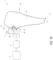
- FIG. 1 Ais a schematic diagram of a system for cleaning a root canal of a tooth, in accordance with the embodiments disclosed herein.
- FIG. 1 Bis a schematic diagram of the system of FIG. 1 A , in which the system is configured to obturate the root canal, in accordance with the embodiments disclosed herein.
- FIG. 1 Cis a schematic diagram of a system that includes components configured to clean unhealthy or undesirable material from a treatment region on an exterior surface of the tooth.
- FIG. 1 Dis a schematic diagram of the system of FIG. 1 C , in which the system is configured to fill the cleaned treatment region, in accordance with the embodiments disclosed herein.
- FIGS. 2 A and 2 Bare graphs that schematically illustrate possible examples of power that can be generated by different embodiments of a pressure wave generator.
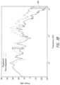
- FIG. 2 Cis a graph of an acoustic power spectrum generated at multiple frequencies by pressure wave generators disclosed herein.
- FIG. 3 Aillustrates images of root canals that compare the use of non-degassed liquid and degassed liquid in the disclosed pressure wave generators.
- FIG. 3 Bis a plot comparing the power output for techniques using non-degassed and degassed liquids.
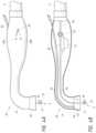
- FIG. 4 Ais a schematic side view of a tooth coupler comprising a handpiece having a cleaning mode and an obturation or filling mode.
- FIG. 4 Bis a schematic side cross-sectional view of the handpiece shown in FIG. 4 A .
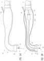
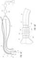
- FIG. 5 Ais a schematic side view of a treatment handpiece configured to deliver a flowable obturation or filler material to a treatment region of a tooth.
- FIG. 5 Bis a schematic side cross-sectional view of the handpiece shown in FIG. 5 A .
- FIG. 6 Ais a schematic side view of a handpiece having a cleaning mode and an obturation or filling mode.
- FIG. 6 Bis a schematic side cross-sectional view of the handpiece shown in FIG. 6 A .
- FIG. 6 Cis a side cross-sectional view of a handpiece configured to couple to a console by way of an interface member and a cartridge configured to be disposed between the interface member and the console.
- FIG. 6 Dis a schematic, cross-sectional magnified view of a cartridge disposed proximal a handpiece.
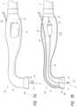
- FIG. 7 Ais a schematic side view of a handpiece having a removable obturation reservoir.
- FIG. 7 Bis a schematic side cross-sectional view of the handpiece shown in FIG. 7 A .
- FIG. 8 Ais a schematic side cross-sectional view of a handpiece configured to deliver a first composition and a second composition to a treatment region of a tooth to obturate or fill the treatment region, according to one embodiment.
- FIG. 8 Bis a schematic side cross-sectional view of a handpiece configured to deliver a first composition and a second composition to fill a treatment region of a tooth, according to another embodiment.
- FIG. 8 Cis a schematic side cross-sectional view of a handpiece configured to deliver multiple components of an obturation material to the treatment region, according to one embodiment.
- FIG. 8 Dis a schematic side cross-sectional view of a handpiece configured to deliver multiple components of an obturation material to the treatment region, according to another embodiment.
- FIG. 9 Ais a photograph illustrating a cross-sectional view of an obturated root canal that was filled in a procedure in accordance with various embodiments disclosed herein.
- FIG. 9 Bis a scanning electron micrograph of a split, obturated root that was filled in the procedure of FIG. 9 A .
- FIG. 1 Ais a schematic diagram of a system 1 , in accordance with the embodiments disclosed herein.
- the system 1 shown in FIG. 1 Amay be configured to perform various types of treatment procedures, including, e.g., cleaning treatments, obturation treatments, restoration treatments, etc.
- the system 1is illustrated as being coupled to (e.g., positioned against in some arrangements) a tooth 10 that is a molar tooth of a mammal, such as a human.
- the tooth 10may be any other suitable type of tooth, such as a pre-molar, bicuspid, incisor, canine, etc.
- the system 1 shown in FIG. 1 Acan include components configured to remove unhealthy or undesirable materials from a tooth or surrounding gum tissue, for example, a root canal 13 of the tooth 10 .
- the system 10is configured to clean the tooth 10 .
- the tooth 10includes hard structural and protective layers, including a hard layer of dentin 16 and a very hard outer layer of enamel 17 .
- a pulp cavity 11is defined within the dentin 16 .
- the pulp cavity 11comprises one or more root canals 13 extending toward an apex 14 of each root 12 .
- the pulp cavity 11 and root canal 13contain dental pulp, which is a soft, vascular tissue comprising nerves, blood vessels, connective tissue, odontoblasts, and other tissue and cellular components. Blood vessels and nerves enter/exit the root canal 13 through a tiny opening, the apical foramen or apical opening 15 , near a tip of the apex 14 of the root 12 .
- the tooth 10 illustrated hereinis a molar
- the embodiments disclosed hereincan advantageously be used to treat any suitable type of tooth, including pre-molars, canines, incisors, etc.
- the system 1can be used to remove unhealthy materials (such as organic and inorganic matter) from an interior of the tooth 10 , e.g., from the root canal 13 of the tooth 10 .
- unhealthy materialssuch as organic and inorganic matter
- an endodontic access opening 18can be formed in the tooth 10 , e.g., on an occlusal surface, a buccal surface, or a lingual surface.
- the access opening 18provides access to a portion of a pulp cavity 11 of the tooth 10 .
- the system 1can include a console 2 , a pressure wave generator 5 , and a tooth coupler 3 (such as a handpiece) adapted to couple to the tooth 10 .
- the tooth coupler 3can couple to the tooth 10 in any suitable way.
- the tooth coupler 3can be positioned against and/or attach to the tooth 10 by way of a tooth seal 75 .
- the cliniciancan hold the tooth coupler 3 against the tooth 10 during treatment.
- the tooth coupler 3can define a chamber 6 configured to retain fluid therein.
- the pulp cavity 11can define a tooth chamber configured to retain fluid therein.
- the tooth coupler 3may not define a chamber, and the tooth chamber defined at least in part by the pulp cavity 11 can retain fluid.
- the tooth coupler 3 disclosed hereincan be any suitable structure or housing configured to couple to the tooth 10 for a treatment procedure.
- “couple”is meant to include arrangements in which there is a connection with the tooth 10 , as well as arrangements in which the coupler 3 is placed against or in the tooth and is held by the clinician in that position.
- the pressure wave generator 5can be coupled to and/or disposed in or on the tooth coupler 3 in various embodiments.
- a system interface member 4can electrically, mechanically, and/or fluidly connect the console 2 with the tooth coupler 3 and pressure wave generator 5 .
- the system interface member 4can removably couple the tooth coupler 3 to the console 2 .
- the clinicianmay use the tooth coupler 3 one time (or a few times), and may dispose the tooth coupler 3 after each procedure (or after a set number of procedures).
- the console 2 and interface member 4may be reused multiple times to removably couple (e.g., to connect and/or disconnect) to multiple tooth couplers 3 using suitable engagement features, as discussed herein.
- the interface member 4can include various electrical and/or fluidic pathways to provide electrical, electronic, and/or fluidic communication between the console 2 and the tooth coupler 3 .
- the console 2can include a control system and various fluid and/or electrical systems configured to operate the pressure wave generator 5 during a treatment procedure.
- the console 2can also include a management module configured to manage data regarding the treatment procedure.
- the console 2can include a communications module configured to communicate with external entities about the treatment procedures.
- the system 1can be used in cleaning procedures to clean substantially the entire root canal system.
- the system 1can be used to fill substantially the entire root canal system with an obturation or filler material.
- the system 1can be used to restore a tooth 10 .
- the chamber 6 of the tooth coupler 3 and/or the pulp cavity 11 of the tooth 10can be at least partially (or substantially) filled with a fluid 22 .
- the pressure wave generator 5can generate pressure waves 23 that propagate through the fluid 22 .
- the generated pressure waves 23may be of sufficient power and relatively low frequencies to produce fluid motion 24 in the pulp cavity 11 of the tooth 10 , the root canal 13 , and/or in the chamber 6 of the tooth coupler 3 .
- the pressure wave generator 5can also generate pressure waves of sufficient power and relatively higher frequencies to produce surface effect cavitation and/or microscale fluid motion created by the impact of the waves on a surface, either inside or outside the tooth 10 . That is, for example, the pressure wave generators 5 disclosed herein can clean the tooth by generating large-scale or bulk fluid motion 24 in or near the tooth 10 , and by generating smaller-scale fluid motion at higher frequencies.
- the fluid motion 24 in the chamber 6can generate induced fluid motion such as vortices 74 , swirl, etc.
- a high velocity stream of liquidcan pass over an orifice (such as the canals), which can create a high speed stream of liquid transverse to the canals.
- the transverse streammay induce vortices 74 that traverse down the canals 13 .
- the high-pressure streamcan create a low pressure stream that cleans the root canals.
- the pressure waves 23can generate normal stress or shear stress or a combination of both onto the surfaces within the treatment region.
- the pressure wave generator 5 shown in FIG. 1 Ais shown as extending into the tooth, in other arrangements, the pressure wave generator 5 may be disposed outside the tooth, such as within the chamber 6 .
- console 2can include a control system comprising a processor and non-transitory memory.
- Computer-implemented instructionscan be stored on the memory and can be executed by the processor to assist in controlling cleaning and/or filling procedures. Additional details of the console 2 may be found in U.S. patent application Ser. No. 14/172,809, filed on Feb. 4, 2014, entitled “DENTAL TREATMENT SYSTEM,” and in U.S. Patent Publication No. US 2012/0237893, each of which is incorporated by reference herein in its entirety and for all purposes.
- FIG. 1 Bis a schematic diagram of the system 1 , in which the system is configured to obturate or fill the root canals 13 of the tooth 10 .
- the systemcan include a pressure wave generator 5 , a tooth coupler 3 , an interface member 4 , and a console 2 .
- the system 1is used to fill or obturate the root canal 13 with an obturation material 45 .
- the cliniciancan clean the root canal 13 in any suitable way, such as by using drills or files, or by using a pressure wave generator (which may be the same as or different from the pressure wave generator 5 shown in FIG. 1 B ).
- the cliniciancan supply an obturation material 45 in its flowable state to the pulp cavity 11 , canals 13 , or other internal chambers of the tooth 10 .
- the cliniciancan supply the obturation material 45 to the treatment region (e.g., the root canal) in any suitable manner.
- the pressure wave generator 5(which may be coupled to or formed with a handpiece) may have one or more openings (see, e.g., FIGS. 4 A- 4 B , et seq.) configured to deliver the flowable obturation material 45 to the tooth 10 .
- the cliniciancan supply the obturation material 45 to the tooth by manually placing it in the tooth 10 , e.g., by hand, by syringe, or by a mechanical tool.
- a dental handpiececan include one or more supply lines that are configured to route the flowable obturation material 45 to the tooth 10 .
- the obturation material 45can be any suitable obturation material disclosed herein.
- the obturation material 45can have a flowable state in which the obturation material 45 flows through the treatment region to fill the root canals 13 and/or pulp cavity 11 .
- the obturation material 45can have a hardened state in which the obturation material 45 solidifies after filling the treatment region.
- the pressure wave generator 5can be activated to enhance the obturation procedure.
- the pressure wave generator 5can be activated to assist in flowing the obturation material 45 throughout the treatment region to be filled.
- the pressure wave generator 45can thereby assist in substantially filling the tooth 10 .
- the pressure wave generator 5when activated, can cause the obturation material 45 to flow into major canal spaces 51 of the tooth 10 , as well as into small spaces 53 of the tooth 10 .
- the system 1 shown in FIG. 1 Bcan assist in filling even small cracks, tubules, and other tiny spaces (e.g., the small spaces 53 ) of the tooth 10 .
- the system 1can ensure a more robust obturation procedure which results in long-term health benefits for the patient.
- the pressure waves 23 and/or fluid motion 24(which may include vortices 74 ) generated by the pressure wave generator 5 may interact with the obturation material 45 to assist in filling the small spaces 53 and the major spaces 51 of the tooth 10 .
- the pressure wave generator 5can be activated to assist in curing or hardening the obturation material 45 .
- some types of obturation materialsmay cure or harden (or the curing or hardening may be enhanced) when agitated by pressure waves 23 generated by the pressure wave generator 5 .
- the obturation or filling materialcan be degassed, which can help deliver the obturation material to small spaces of the tooth. Accordingly, the pressure wave generator 5 can enhance the obturation procedure in a variety of ways.
- the obturation material 45is supplied to the tooth 10 , and the pressure wave generator 5 is subsequently activated to enhance the obturation procedure (e.g., to improve the filling process and/or to enhance or activate the curing process).
- the cliniciancan supply the obturation material 45 to the tooth 10 using a syringe or other device, and the pressure wave generator 5 can subsequently (or concurrently) be activated to fill the treatment region.
- the pressure wave generator 5can supply the obturation material 45 and generate pressure waves through the obturation material (or other fluids at the treatment region).
- supplying the obturation material and generating pressure wavescan occur substantially simultaneously, or can overlap by some amount over time.
- the pressure wave generator 5can be activated to supply the obturation material 45 to the treatment region.
- a jet of obturation material 45can interact with fluids in the tooth 10 (e.g., other portions of the obturation material or other treatment fluid) to generate pressure waves that propagates through the fluids.
- the resulting pressure wavescan enhance the obturation procedure.
- different types of fluidse.g., water or other treatment fluids
- the jetcan pass through obturation materials in the treatment region. Interaction of the fluid jet and the obturation material can enhance the obturation procedure.
- the pressure wave generator 5can comprise any suitable type of pressure wave generator, e.g., a liquid jet device, a laser, a mechanical stirrer, an ultrasonic transducer, etc.
- the pressure wave generator 5can be sized such that the pressure wave generator 5 is disposed outside the region of the tooth 10 that is to be obturated.
- the pressure wave generator 5can be disposed in the chamber 6 such that it is disposed outside the tooth 10 .
- the pressure wave generator 5can extend partially into the tooth 10 .
- the pressure wave generator 5can extend to a depth that does not interfere with the filling.
- the system 1can include a cleaning mode for cleaning the treatment region and a filling mode to fill or obturate the treatment region.
- the console 2can include a control system comprising a processor and memory. The control system can be programmed or configured to switch the system 1 from the cleaning mode to the filling mode and vice versa. The control system of the console 2 can also control the operation of cleaning and/or filling procedures.
- FIG. 1 Cis a schematic diagram of a system 1 that includes components configured to clean unhealthy or undesirable material from a treatment region 20 on an exterior surface of the tooth 10 .
- the system 1can include a tooth coupler 3 and a pressure wave generator 5 .
- the tooth coupler 3can communicate with a console 2 by way a system interface member 4 .
- the tooth coupler 3is coupled to (e.g., positioned against by a clinician) a treatment region 20 on an exterior surface of the tooth 10 .
- the tooth coupler 3can be stably positioned against the treatment region and can be sealed to the tooth 10 , e.g., by way of an adhesive or other seal.
- the system 1 of FIG. 1 Ccan be activated to clean an exterior surface of the tooth 10 , e.g., a carious region of the tooth 10 and/or remove undesirable dental deposits, such as plaque, calculus biofilms, bacteria, etc, from the tooth 10 and/or surround gum tissue.
- the system 1can be activated to fill a treated region on the exterior surface of the tooth 10 with a filling or restoration material.
- pressure waves 23 and/or fluid motion 24can be generated in the tooth coupler 3 and chamber 6 , which can act to clean the treatment region 20 of the tooth 10 , forming a cleaned treatment region 20 A in which the carious (or other unhealthy material) is removed.
- Patent Publication No. US 2014/0099597filed Apr. 11, 2013, entitled “APPARATUS AND METHODS FOR CLEANING TEETH AND GINGIVAL POCKETS,” each of which is incorporated by reference herein in its entirety and for all purposes.
- FIG. 1 Dis a schematic diagram of the system 1 of FIG. 1 C , in which the system 1 is configured to fill the treated carious region 20 A of the tooth 10 .
- the systemcan include a pressure wave generator 5 , a tooth coupler 3 , an interface member 4 , and a console 2 .
- the cliniciancan fill the cleaned treatment region 20 A with a suitable filler or obturation material 45 .
- the obturation material 45can be supplied to the cleaned treatment region 20 A.
- the pressure wave generator 5can act to substantially fill the treatment region 20 A and/or to enhance or activate the hardening of the filler obturation material 45 .
- the filler or obturation material 45is supplied to the tooth 10 , and the pressure wave generator 5 is subsequently activated to enhance the filling procedure (e.g., to improve the filling process and/or to enhance or activate the curing process).
- the cliniciancan supply the filler or obturation material 45 to the treatment region 20 A using a syringe, and the pressure wave generator 5 can subsequently be activated to fill the treatment region.
- the pressure wave generator 5is activated to supply the filler or obturation material 45 to the treatment region 20 A and to generate pressure waves through the material.
- the pressure wave generator 5comprises a liquid jet
- a jet of obturation or filler material 45can interact with fluids at the treatment region 20 A (e.g., other portions of the filler or obturation material or other treatment fluid) to generate pressure waves that propagates through the fluids.
- the resulting pressure wavescan enhance the obturation procedure.
- the system 1 disclosed hereincan be used with various types of treatment procedures.
- some embodiments disclosed hereincan advantageously remove undesirable or unhealthy materials from a tooth such that substantially all the unhealthy material is removed while inducing minimal or no discomfort and/or pain in the patient.
- the pressure wave generator 5when activated by the clinician, can induce various fluidic effects that interact with the unhealthy material to be removed, even when the pressure wave generator 5 is disposed at a position remote from the treatment region of the tooth, e.g., the region of the tooth that includes the unhealthy or undesirable material to be removed.
- the pressure wave generator 5can impart energy to a fluid 22 that induces the relatively large-scale or bulk circulation or movement 24 of liquid in the chamber 6 and/or tooth 10 , and that also generates pressure waves 23 that propagate through the fluid 22 and tooth 10 .
- the generated fluid motion 24 and pressure waves 23can magnify or enhance the properties of the fluid 22 to enhance cleaning of the tooth 10 .
- the pressure wave generator 5can be used to obturate or fill the root canals and/or other treated regions of the tooth, and can also be used to restore or build up a damaged or diseased tooth.
- the system 1 disclosed hereincan be used to clean teeth.
- the system 1can be configured to clean organic and inorganic material, including diseased pulp, bacteria, etc., from root canals of the tooth 10 .
- the system 1can be configured to remove carious regions of the tooth 10 , e.g., regions of the tooth 10 that are decayed. The carious regions can be formed on an exterior surface of the tooth 10 in some arrangements.
- the system 1can be configured to clean undesirable dental deposits from exterior surfaces of the tooth 10 , including plaque, calculus, biofilms, bacteria, and other unhealthy deposits.
- the system 1can utilize, alone or in combination, the chemistry of various treatment fluids, pressure waves generated by the pressure wave generator 5 , and fluid motion 24 created in the chamber 6 of the tooth coupler 3 and/or in a chamber within the tooth 10 .
- the fluid 22 supplied to the chamber 6 and/or to the pulp cavity 11 of the tooth 10can comprise a treatment fluid that can be introduced into the tooth 10 and the chamber 6 to assist in removing unhealthy or undesirable materials from the tooth 10 .
- the treatment fluidscan be selected based on the chemical properties of the fluids when reacting with the undesirable or unhealthy material to be removed from the tooth 10 .
- the treatment fluids disclosed hereincan include any suitable fluid, including, e.g., water, saline, etc.
- tissue dissolving agentse.g., NaOCl or bleach
- disinfectantse.g., chlorhexidine
- fluoride therapy agentse.g., fluoride therapy agents
- EDTAethylenediaminetetraacetic acid
- citric acide.g., citric acid
- any other antibacterial, decalcifying, disinfecting, mineralizing, or whitening solutionsmay be used as well.
- the cliniciancan supply the various fluids to the tooth in one or more treatment cycles, and can supply different fluids sequentially or simultaneously.
- bleach-based solutionse.g., solutions including NaOCl
- can be used to dissociate diseased tissuee.g., diseased organic matter in the root canal 13
- bacteria, biofilm or endotoxinsLipopolysaccharide or LPS
- a treatment solutioncomprises water or saline with 0.3% to 6% bleach (NaOCl).
- tissue dissolution and dental deposit removal in the presence of bleachmay not occur when the bleach concentration is less than 1%.
- tissue dissolution and dental deposit removalcan occur at smaller (or much smaller) concentrations.
- the cliniciancan supply an EDTA-based solution to remove undesirable or unhealthy calcified material from the tooth 10 .
- a smear layermay form on the walls of the canal 13 .
- the smear layercan include a semi-crystalline layer of debris, which may include remnants of pulp, bacteria, dentin, and other materials.
- Treatment fluids that include EDTAmay be used to remove part or all of the smear layer, and/or calcified deposits on the tooth 10 .
- EDTAmay also be used to remove dentin packed into isthmuses and lateral canals during the instrumentation process.
- EDTAmay also be used to remove a microscopic layer off enamel and cleaning and staining purposes. Other chemicals such as citric acid may also be used for similar purposes.
- the clinicianmay supply a treatment fluid that comprises substantially water.
- the watercan be used to assist in irrigating the tooth before, during, and/or after the treatment.
- the watercan be supplied to remove remnants of other treatment fluids (e.g., bleach or EDTA) between treatment cycles.
- bleachhas a pH that tends to be a base and because EDTA is an acid, it can be important to purge the tooth 10 and chamber 6 between bleach and EDTA treatments to avoid potentially damaging chemical reactions.
- the watercan be supplied with a sufficient momentum to help remove detached materials that are disrupted during the treatment.
- the watercan be used to convey waste material from the tooth 10 .
- chemicals and the concentrations of the chemicalscan be varied throughout the procedure by the clinician and/or by the system to improve patient outcomes.
- the cliniciancan alternate between the use of water, bleach, and EDTA, in order to achieve the advantages associated with each of these chemicals.
- the clinicianmay begin with a water cycle to clean out any initial debris, then proceed with a bleach cycle to dissociate diseased tissue and bacteria from the tooth.
- a water cyclemay then be used to remove the bleach and any remaining detached materials from the tooth 10 .
- the clinicianmay then supply EDTA to the tooth to remove calcified deposits and/or portions of a smear layer from the tooth 10 .
- Watercan then be supplied to remove the EDTA and any remaining detached material from the tooth 10 before a subsequent bleach cycle.
- the cliniciancan continually shift between cycles of treatment fluid throughout the procedure.
- the above exampleis for illustrative purposes only. It should be appreciated that the order of the cycling of treatment liquids may vary in any suitable manner and order.
- the treatment fluids used in the embodiments disclosed hereincan react chemically with the undesirable or unhealthy materials to dissociate the unhealthy materials from the healthy portions of the tooth 10 .
- the treatment fluidscan also be used to irrigate waste fluid and/or detached or delaminated materials out of the tooth 10 .
- the treatment solution(including any suitable composition) can be degassed, which may improve cavitation and/or reduce the presence of gas bubbles in some treatments.
- the dissolved gas contentcan be less than about 1% by volume.
- a pressure wave generator 5can remove unhealthy materials from a tooth by propagating pressure waves 23 through a propagation medium such as the fluid 22 (e.g., the treatment fluid) to the treatment region, which can include one or more teeth and/or gums.
- a propagation mediumsuch as the fluid 22 (e.g., the treatment fluid)
- the treatment regionwhich can include one or more teeth and/or gums.
- the pressure wave generators disclosed hereinmay also be used to effectively obturate or fill treatment regions of the tooth. Note that these principles, and the principles described above, may be generally applicable for each embodiment disclosed herein.
- cavitationmay be induced by the generated pressure waves 23 .
- a liquide.g., water or other treatment fluid
- acoustic cavitationmay occur.
- the oscillation or the implosive collapse of small cavitation bubblescan produce localized effects, which may further enhance the cleaning process, e.g., by creating intense, small-scale localized heat, shock waves, and/or microjets and shear flows. Therefore, in some treatment methods, acoustic cavitation may be responsible for or involved in enhancing the chemical reactions, sonochemistry, sonoporation, soft tissue/cell/bacteria dissociation, delamination and breakup of biofilms.
- the pressure waves 23may enhance the chemical reaction via convection, turbulence, agitation and/or sonochemistry.
- the pressure waves 23can enhance the chemical effects that each composition has on the unhealthy material to be removed from the tooth.
- the generated pressure waves 23can propagate so as to dissociate tissue throughout the entire tooth 10 , including in the dentinal tubules and throughout tiny cracks and crevices of the tooth 10 .
- the generated pressure waves 23can propagate so as to remove the smear layer and/or calcified deposits from the tooth 10 , including in the tubules and/or in tiny cracks and crevices formed in the tooth 10 .
- the generated pressure waves 23can propagate so as to flush and/or irrigate undesirable materials from the tooth, including in tubules and tiny cracks and crevices. Accordingly, the generated pressure waves 23 can enhance the removal of undesirable or unhealthy materials from the tooth 10 by magnifying the chemical effects of whatever treatment fluid composition is used during a particular treatment cycle.
- sonoporationwhich is the process of using pressure waves and/or the subsequent acoustic cavitation to modify the permeability of the bacterial cell plasma membrane, may also expedite the chemical reaction that removes the microorganisms from the tooth.
- generated pressure waves, and/or the subsequent acoustic cavitation of certain frequenciesmay result in cellular and bacterial rupture and death (e.g., lysis) as well as removal of decayed and weakened dentin and enamel.
- the cellular and bacterial rupture phenomenonmay kill bacteria which might otherwise reinfect the gingival pockets and/or the oral cavity.
- Generated pressure waves and/or the subsequent acoustic cavitationmay also loosen the bond of the structure of the unhealthy material (e.g., diseased tissue, calculus, biofilm, caries, etc.), and/or the pressure waves may dissociate the unhealthy material from the tooth 10 .
- pressure waves and/or acoustic cavitationmay loosen the bond between the cells and the dentin and/or delaminate the tissue from the tooth.
- the pressure waves and/or the subsequent acoustic cavitationmay act on decayed hard tissue (which may be relatively weak and loosely connected) through vibrations and/or shock waves, and/or the microjets created as a result of cavitation bubble implosion, to remove decayed hard tissue from other healthy portions of the tooth.
- a pressure wave generator 5can be used in various disclosed embodiments to clean a tooth 10 , e.g., from interior or exterior portions of the tooth 10 and/or gums. In other embodiments, the pressure wave generator 5 can be used to fill or obturate a cleaned root canal or other treatment region of the tooth 10 . In some embodiments, the pressure wave generator 5 can comprise an elongated member having an active distal end portion. The active distal end portion can be activated by a user to apply energy to the treatment tooth 10 to remove unhealthy or undesirable material from the tooth 10 .
- the disclosed pressure wave generators 5can be configured to generate pressure waves 23 and fluid motion 24 with energy sufficient to clean undesirable material from a tooth 10 .
- the pressure wave generator 5can be a device that converts one form of energy into acoustic waves and bulk fluid motion (e.g., rotational motion) within the fluid 22 .
- the pressure wave generator 5can induce, among other phenomena, both pressure waves and bulk fluid dynamic motion in the fluid 22 (e.g., in the chamber 6 ), fluid circulation, turbulence, vortices and other conditions that can enable the cleaning of the tooth.
- the pressure wave generator 5 disclosed in each of the figures described hereinmay be any suitable type of pressure wave generator.
- the pressure wave generator 5can be used to clean the tooth 10 by creating pressure waves that propagate through the fluid 22 , e.g., through treatment fluid at least partially retained in the chamber 6 .
- the pressure wave generator 5may also create cavitation, acoustic streaming, turbulence, etc.
- the pressure wave generator 5e.g., high-speed liquid jet, ultrasonic transducer, a laser fiber, etc.
- the pressure wave generator 5can be placed at the desired treatment location in or on the tooth 10 .
- the pressure wave generator 5can create pressure waves 23 and fluid motion 24 within the fluid 22 inside a substantially-enclosed chamber 6 and/or in a tooth chamber of the tooth (e.g., the pulp cavity 11 and/or the root canal 13 ).
- the pressure wave generator 5can be sufficiently strong to remove unhealthy materials such as organic and/or inorganic tissue from teeth 10 .
- the pressure wave generator 5can be configured to avoid substantially breaking down or harming natural dentin and/or enamel.
- the pressure wave generator 5can comprise a liquid jet device.
- the liquid jetcan be created by passing high pressure liquid through an orifice.
- the liquid jetcan create pressure waves within the treatment liquid.
- the pressure wave generator 5comprises a coherent, collimated jet of liquid.
- the jet of liquidcan interact with liquid in a substantially-enclosed volume (e.g., the chamber 6 , the tooth chamber (e.g., pulp cavity 11 and/or root canals 13 ), and/or the mouth of the user) and/or an impingement member to create the acoustic waves.
- the interaction of the jet and the treatment fluid, as well as the interaction of the spray which results from hitting the impingement member and the treatment fluid,may assist in creating cavitation and/or other acoustic and fluid motion effects to clean the tooth.
- the liquid jet apparatuscan be configured to clean and/or fill or obturate a treatment region of the tooth.
- the liquid jet devicecan comprise a positioning member (e.g., a guide tube) having a channel or lumen along which or through which a liquid jet can propagate.
- the distal end portion of the positioning membercan include one or more openings that permit the deflected liquid to exit the positioning member and interact with the surrounding environment in the chamber 6 and/or tooth 10 .
- the openings disposed at or near the distal end portion of the positioning membercan be submerged in liquid that can be at least partially enclosed in the tooth coupler 3 attached to or enclosing a portion of the tooth 10 .
- the liquid jetcan pass through the guide tube and can impact an impingement surface.
- the passage of the jet through the surrounding treatment fluid and impact of the jet on the impingement surfacecan generate the acoustic waves in some implementations.
- the flow of the submerged portion of the liquid jetmay generate a cavitation cloud within the treatment fluid.
- the creation and collapse of the cavitation cloudmay, in some cases, generate a substantial hydroacoustic field in or near the tooth. Further cavitation effects may be possible, including growth, oscillation, and collapse of cavitation bubbles.
- bulk fluid motionsuch as rotational flow, may be induced.
- the induced rotational flowcan enhance the cleaning process by removing detached material and replenishing reactants for the cleaning reactions. These (and/or other) effects may lead to efficient cleaning of the tooth.
- the rotational flowmay also create sufficient shear stress onto surface which then leads to dissociation, detachment, and delamination of unhealthy materials.
- the rotational flowmay include turbulent regions working on small scale regions or small scale unhealthy materials.
- a pressure wave generator and/or pressure wave generator that includes a liquid jet devicemay be found at least in ⁇ [0045]-[0050], [0054]-[0077] and various other portions of U.S. Patent Publication No. US 2011/0117517, published May 19, 2011, and in ⁇ [0136]-[0142] and various other portions of U.S. Patent Publication No. US 2012/0237893, published Sep. 20, 2012, each of which is incorporated by reference herein in its entirety and for all purposes.
- a pressure wave generatorcan be any physical device or phenomenon that converts one form of energy into acoustic waves within the treatment fluid and that induces normal and shear stresses as well as small scale flows near a treatment region in the chamber 6 and/or tooth 10 .
- the pressure wave generator 5may also convert the energy into rotational fluid motion of various length scales in the chamber 6 and/or tooth 10 .
- Many different types of pressure wave generators(or combinations of pressure wave generators) are usable with embodiments of the systems and methods disclosed herein.
- Mechanical energy pressure wave generatorscan also include rotating objects, e.g. miniature propellers, eccentrically-confined rotating cylinders, a perforated rotating disk, etc. These types of pressure wave generators can also include vibrating, oscillating, or pulsating objects such as sonication devices that create pressure waves via piezoelectricity, magnetostriction, etc. In some pressure wave generators, electric energy transferred to a piezoelectric transducer can produce acoustic waves in the treatment fluid. In some cases, the piezoelectric transducer can be used to create acoustic waves having a broad band of frequencies. Mechanical pressure wave generators can be configured to clean and/or fill or obturate a treatment region of the tooth.
- Electromagnetic pressure wave generatorscan also be configured to clean and/or fill or obturate a treatment region of the tooth.
- An electromagnetic beam of radiatione.g., a laser beam
- the electromagnetic beam energycan be transformed into acoustic waves as it enters the treatment fluid.
- the laser beamcan be directed into the chamber 6 and/or tooth coupler 3 as a collimated and coherent beam of light.
- the collimated laser beamcan be sufficient to generate pressure waves as the laser beam delivers energy to the fluid.
- the laser beamcan be focused using one or more lenses or other focusing devices to concentrate the optical energy at a location in the treatment fluid. The concentrated energy can be transformed into pressure waves sufficient to clean the undesirable materials.
- the wavelength of the laser beam or electromagnetic sourcecan be selected to be highly absorbable by the treatment fluid in the chamber, tooth, and/or mouth (e.g., water) and/or by the additives in the treatment fluid (e.g., nanoparticles, etc.).
- the electromagnetic energycan be absorbed by at least one component and can turn the electromagnetic energy into either heat, vibration, or pressure waves, for example, through cavitation.
- at least some of the electromagnetic energymay be absorbed by the fluid (e.g., water) in the chamber, which can generate localized heating and pressure waves that propagate in the fluid.
- the pressure waves generated by the electromagnetic beamcan generate light-induced cavitation effects in the fluid.
- the localized heatingcan induce rotational fluid flow in the chamber 6 and/or tooth 10 that further enhances cleaning of the tooth 10 .
- the electromagnetic radiation from a radiation sourcee.g., a laser
- an optical waveguidee.g., an optical fiber
- dispersed into the fluid at a distal end of the waveguidee.g., a shaped tip of the fiber, e.g., a conically-shaped tip.
- the radiationcan be directed to the chamber by a beam scanning system.
- the wavelength of the electromagnetic energymay be in a range that is strongly absorbed by water molecules.
- the wavelengthmay in a range from about 300 nm to about 3000 nm.
- the wavelengthis in a range from about 400 nm to about 700 nm, about 700 nm to about 1000 nm (e.g., 790 nm, 810 nm, 940 nm, or 980 nm), in a range from about 1 micron to about 3 microns (e.g., about 2.7 microns or 2.9 microns), or in a range from about 3 microns to about 30 microns (e.g., 9.4 microns or 10.6 microns).
- the electromagnetic energycan be in the ultraviolet, visible, near-infrared, mid-infrared, microwave, or longer wavelengths.
- the electromagnetic energycan be pulsed or modulated (e.g., via a pulsed laser), for example with a repetition rate in a range from about 1 Hz to about 500 kHz.
- the pulse energycan be in a range from about 1 mJ to about 1000 mJ.
- the pulse widthcan be in a range from about 1 ⁇ s to about 500 ⁇ s, about 1 ms to about 500 ms, or some other range.
- nanosecond pulsed laserscan be used with pulse rates in a range from about 100 ns to about 500 ns.
- the foregoingare non-limiting examples of radiation parameters, and other repetition rates, pulse widths, pulse energies, etc. can be used in other embodiments.
- the lasercan include one or more of a diode laser, a solid state laser, a fiber laser, an Er:YAG laser, an Er:YSGG laser, an Er,Cr:YAG laser, an Er,Cr:YSGG laser, a Ho:YAG laser, a Nd:YAG laser, a CTE:YAG laser, a CO 2 laser, or a Ti:Sapphire laser.
- the source of electromagnetic radiationcan include one or more light emitting diodes (LEDs).
- the electromagnetic radiationcan be used to excite nanoparticles (e.g., light-absorbing gold nanorods or nanoshells) inside the treatment fluid, which may increase the efficiency of photo-induced cavitation in the fluid.
- the treatment fluidcan include excitable functional groups (e.g., hydroxyl functional groups) that may be susceptible to excitation by the electromagnetic radiation and which may increase the efficiency of pressure wave generation (e.g., due to increased absorption of radiation).
- excitable functional groupse.g., hydroxyl functional groups
- radiation having a first wavelengthcan be used (e.g., a wavelength strongly absorbed by the liquid, for instance water) followed by radiation having a second wavelength not equal to the first wavelength (e.g., a wavelength less strongly absorbed by water) but strongly absorbed by another element, e.g. dentin, dyes, or nanoparticles added to solution.
- the first wavelengthmay help create bubbles in the fluid
- the second wavelengthmay help disrupt the tissue.
- the electromagnetic energycan be applied to the chamber 6 for a treatment time that can be in a range from about one to a few seconds up to about one minute or longer.
- a treatment procedurecan include one to ten (or more) cycles of applying electromagnetic energy to the tooth.
- a fluidcan circulate or otherwise move in the chamber during the treatment process, which advantageously may inhibit heating of the tooth 10 (which may cause discomfort to the patient).
- the movement or circulation of treatment fluide.g., water with a tissue dissolving agent
- movement of the treatment fluidfor example small- or large scale rotational flows or turbulent flow
- can increase the effectiveness of the cleaningas compared to a treatment with little or no fluid circulation).
- electromagnetic energycan be added to other fluid motion generation modalities.
- electromagnetic energycan be delivered to a chamber in which another pressure wave generator (e.g., a liquid jet) is used to generate the acoustic waves.
- another pressure wave generatore.g., a liquid jet
- Acoustic energycan be generated from electric energy transferred to, e.g., an ultrasound or other transducer or an ultrasonic tip (or file or needle) that creates acoustic waves in the treatment fluid.
- the ultrasonic or other type of acoustic transducercan comprise a piezoelectric crystal that physically oscillates in response to an electrical signal or a magnetostrictive element that converts electromagnetic energy into mechanical energy.
- the transducercan be disposed in the treatment fluid, for example, in the fluid inside the chamber.
- ultrasonic or other acoustic devices used with the embodiments disclosed hereinare preferably broadband and/or multi-frequency devices.
- a pressure wave generator 5can be placed at a desired location with respect to the tooth 10 .
- the pressure wave generator 5creates pressure waves within the fluid 22 inside the chamber 6 and/or tooth 10 (the generation of acoustic waves may or may not create or cause cavitation).
- the acoustic or pressure waves 23propagate throughout the fluid 22 inside the chamber 6 of the tooth coupler 3 and/or in a tooth chamber of the tooth 10 , with the fluid 22 in the chamber 6 or tooth 10 serving as a propagation medium for the pressure waves 23 .
- the pressure waves 23can also propagate through tooth material (e.g., dentin).
- acoustic cavitationmay occur.
- the collapse of cavitation bubblesmay induce, cause, or be involved in a number of processes described herein such as, e.g., sonochemistry, tissue dissociation, tissue delamination, sonoporation, and/or removal of calcified structures.
- the pressure wave generatorcan be configured such that the acoustic waves (and/or cavitation) do not substantially break down natural dentin in the tooth 110 .
- the acoustic wave field by itself or in addition to cavitationmay be involved in one or more of the abovementioned processes.
- the pressure wave generator 5generates primary cavitation, which creates acoustic waves, which may in turn lead to secondary cavitation.
- the secondary cavitationmay be weaker than the primary cavitation and may be non-inertial cavitation.
- the pressure wave generator 5generates acoustic waves directly, which may lead to secondary cavitation.
- pressure wave generatorse.g., which may comprise a pressure wave generator
- pressure wave generatorsmay be suitable for use with the embodiments disclosed herein may be found, e.g., in ⁇ [0191]-[0217], and various other portions of U.S. Patent Publication No. US 2012/0237893, published Sep. 20, 2012, which is incorporated by reference herein for all purposes.
- bulk fluid motion 24can enhance the cleaning of unhealthy material from a diseased tooth.
- the fluid motion 24 generated in the chamber 6 and/or tooth 10can impart relatively large momentum to the tooth, which can help dissociate and irrigate unhealthy materials from the tooth.
- the fluid motion 24can induce vortices and/or swirl in the tooth 10 that can result in negative pressures (or low positive pressures) near the apical opening 15 of the tooth 10 .
- the resulting negative pressures at the apical opening 15can prevent or reduce an amount of material extruded through the apical opening 15 and into the jaw of the patient.
- liquid circulation with a time scale comparable to (and preferably faster than) that of chemical reactionmay help replenish the reactants at the chemical reaction front and/or may help to remove the reaction byproducts from the reaction site.
- the relatively large convective time scalewhich may relate to effectiveness of the convection process, can be adjusted and/or optimized depending on, e.g., the location and characteristics of the source of circulation.
- liquid circulation or other fluid motion 24generally does not eliminate the diffusion process, which may still remain effective within a thin microscopic layer at the chemical reaction front.
- Liquid circulationcan also cause a strong irrigation effect at the treatment site (e.g. removing diseased tissue deep in the canal 13 and/or tubules and small spaces and cracks of the tooth 10 ) and may therefore result in loosening and/or removing large and small pieces of debris from the treatment site.
- various propertiescan be adjusted to enhance bulk fluid motion and/or fluid circulation, e.g., fluid motion in the chamber 6 of the tooth coupler 3 .
- the position of the pressure wave generator 5 relative to the location of the treatment sitecan be adjusted.
- the pressure wave generator 5can be disposed adjacent the access opening 18 formed in the tooth and/or adjacent an access port of the tooth coupler 3 .
- the geometry of the space surrounding the pressure wave generator 5 and treatment sitee.g., the geometry of the tooth coupler 3
- circulationmay be affected by the viscosity of the fluid 22 and/or the mechanism of action of the pressure wave generator 5 .
- the pressure wave generator 5such as a jet of liquid ejected through an inlet opening, a stirrer such as a propeller or a vibrating object, etc., can be selected to enhance fluid motion of the treatment fluid.
- the input power of the source of liquid circulationcan also be adjusted, such as the source of a pump that drives a liquid jet in some embodiments.
- the pressure wave generators 5 disclosed hereincan enhance other dental and endodontic procedures. For example, after cleaning a tooth (e.g., a root canal inside the tooth, a carious region on or near an exterior surface of the tooth, etc.), the treatment region can be filled with an obturation or filler material. The clinician can also restore damaged or diseased tooth material by building up the tooth using a suitable restoration material.
- a filler materialcan be supplied to the treatment region as a flowable material and can be hardened to fill the treatment region (e.g., the cleaned root canal or carious region, etc.).
- a pressure wave generator 5can be activated to supply the obturation material throughout the treatment region.
- the pressure wave generatorcan supply the flowable obturation material into the tooth and root canal.
- the large-scale fluid movement generated by the pressure wave generator 5can assist in propagating the obturation material throughout relatively large spaces, such as the main root canal or canals.
- the pressure wave generator 5may introduce sufficient momentum such that the flowable obturation material propagates throughout the canal space without introducing additional instrumentation into the tooth.
- the bulk fluid motion of the obturation material into the canalmay be such that the clinician may not need to or desire to enlarge the canals. By reducing or eliminating canal enlargement, patient outcomes and pain levels can be improved.
- the bulk fluid motion of the flowable obturation materialcan be generated at relatively low frequencies produced by the pressure wave generator.
- the pressure wave generators 5 disclosed hereincan generate higher frequency perturbations to propagate the obturation material into smaller cracks, spaces, and crevices in the tooth.
- higher-frequency effectssuch as acoustic cavitation, can assist in propagating the filler material throughout the tooth.
- the pressure wave generators disclosed hereincan enhance the filling and/or restoration of a treatment region such as a root canal, carious region of the tooth, etc.
- the obturation materialcan be propagated at a distance such that it flows into the treatment region from a remote pressure wave generator 5 (which may be disposed outside the tooth).
- Large-scale or bulk fluid motion of the obturation materialcan fill larger canal spaces or other treatment regions without further enlargening the treatment region.
- Smaller-scale and/or higher frequency agitation by the pressure wave generator 5can propagate the obturation material into smaller cracks and spaces of the tooth.
- FIGS. 2 A and 2 Bare graphs that schematically illustrate possible examples of power that can be generated by different embodiments of the pressure wave generator 5 . These graphs schematically show acoustic power (in arbitrary units) on the vertical axis as a function of acoustic frequency (in kHz) on the horizontal axis.
- the acoustic power in the toothmay influence, cause, or increase the strength of effects including, e.g., acoustic cavitation (e.g., cavitation bubble formation and collapse, normal and shear stress formation, as well as microscale flow and microjet formation), acoustic streaming, microerosion, fluid agitation, turbulence, fluid circulation and/or rotational motion, sonoporation, sonochemistry, and so forth, which may act to dissociate organic material in or on the tooth and effectively clean the undesirable materials, e.g., undesirable organic and/or inorganic materials and deposits.
- these effectscan enhance or enable the obturation or filling of treated root canals or other treatment regions of the tooth.
- the embodiments disclosed hereincan advantageously obturate or fill substantially the entire canal(s) and/or branch structures therefrom, as explained in greater detail above.
- the pressure wave generatorcan produce a pressure wave including acoustic power (at least) at frequencies above: about 1 Hz, about 0.5 kHz, about 1 kHz, about 10 kHz, about 20 kHz, about 50 kHz, about 100 kHz, or greater.
- the pressure wavecan have acoustic power at other frequencies as well (e.g., at frequencies below the aforelisted frequencies).
- the graph in FIG. 2 Arepresents a schematic example of acoustic power generated by a liquid jet impacting a surface disposed within a chamber on or around the tooth that is substantially filled with liquid and by the interaction of the liquid jet with fluid in the chamber.
- This schematic exampleshows a broadband spectrum 190 of acoustic power with significant power extending from about 1 Hz to about 1000 kHz, including, e.g., significant power in a range of about 1 kHz to about 1000 kHz (e.g., the bandwidth can be about 1000 kHz).
- the bandwidth of the acoustic energy spectrummay, in some cases, be measured in terms of the 3-decibel (3-dB) bandwidth (e.g., the full-width at half-maximum or FWHM of the acoustic power spectrum).
- a broadband acoustic power spectrumcan include significant power in a bandwidth in a range from about 1 Hz to about 500 kHz, in a range from about 1 kHz to about 500 kHz, in a range from about 10 kHz to about 100 kHz, or some other range of frequencies.
- a broadband spectrumcan include acoustic power above about 1 MHz.
- the pressure wave generatorcan produce broadband acoustic power with peak power at about 10 kHz and a bandwidth of about 100 kHz.
- the bandwidth of a broadband acoustic power spectrumis greater than about 10 kHz, greater than about 50 kHz, greater than about 100 kHz, greater than about 250 kHz, greater than about 500 kHz, greater than about 1 MHz, or some other value.
- acoustic power between about 1 Hz and about 200 kHz, e.g., in a range of about 20 kHz to about 200 kHzmay be particularly effective at cleaning teeth.
- the acoustic powercan have substantial power at frequencies greater than about 1 kHz, greater than about 10 kHz, greater than about 100 kHz, or greater than about 500 kHz.
- Substantial powercan include, for example, an amount of power that is greater than 10%, greater than 25%, greater than 35%, or greater than 50% of the total acoustic power (e.g., the acoustic power integrated over all frequencies).
- the broadband spectrum 190can include one or more peaks, e.g., peaks in the audible, ultrasonic, and/or megasonic frequency ranges.
- the graph in FIG. 2 Brepresents a schematic example of acoustic power generated by an ultrasonic transducer disposed in a chamber on or around the tooth that is substantially filled with liquid.
- This schematic exampleshows a relatively narrowband spectrum 192 of acoustic power with a highest peak 192 a near the fundamental frequency of about 30 kHz and also shows peaks 192 b near the first few harmonic frequencies.
- the bandwidth of the acoustic power near the peakmay be about 5 to 10 kHz, and can be seen to be much narrower than the bandwidth of the acoustic power schematically illustrated in FIG. 2 A .
- the bandwidth of the acoustic powercan be about 1 kHz, about 5 kHz, about 10 kHz, about 20 kHz, about 50 kHz, about 100 kHz, or some other value.
- the acoustic power of the example spectrum 192has most of its power at the fundamental frequency and first few harmonics, and therefore the ultrasonic transducer of this example may provide acoustic power at a relatively narrow range of frequencies (e.g., near the fundamental and harmonic frequencies).
- the acoustic power of the example spectrum 190exhibits relatively broadband power (with a relatively high bandwidth compared to the spectrum 192 ), and the example liquid jet can provide acoustic power at significantly more frequencies than the example ultrasonic transducer.
- the relatively broadband power of the example spectrum 190illustrates that the example jet device provides acoustic power at these multiple frequencies with energy sufficient to break the bonds between the decayed and healthy material so as to substantially remove the decayed material from the carious region.
- pressure waves having broadband acoustic powercan generate acoustic cavitation or other means of cleaning and disinfection that is more effective at cleaning teeth (including cleaning, e.g., unhealthy materials in or on the tooth) than cavitation generated by pressure waves having a narrowband acoustic power spectrum (see, e.g., the example shown in FIG. 2 B ).
- acoustic cavitation or other means of cleaning and disinfectionthat is more effective at cleaning teeth (including cleaning, e.g., unhealthy materials in or on the tooth) than cavitation generated by pressure waves having a narrowband acoustic power spectrum (see, e.g., the example shown in FIG. 2 B ).
- a broadband spectrumthe energy is delivered as substantially all length scales covered in the range and therefore targeting substantially all structures whose dimensions fall within that range of length scales.
- broadband acoustic powercan also generate sufficient energy at frequencies capable of obturating or filling a root canal or other treatment region (such as a treated carious region on an exterior surface of the tooth).
- a broadband spectrum of acoustic powercan produce a relatively broad range of bubble sizes in the cavitation cloud and on the surfaces on the tooth, and the implosion of these bubbles may be more effective at disrupting tissue than bubbles having a narrow size range.
- Relatively broadband acoustic powermay also allow acoustic energy to work on a range of length scales, e.g., from the cellular scale up to the tissue scale.
- pressure wave generators that produce a broadband acoustic power spectrumcan be more effective at tooth cleaning for some treatments than pressure wave generators that produce a narrowband acoustic power spectrum.
- multiple narrowband pressure wave generatorscan be used to produce a relatively broad range of acoustic power.
- multiple ultrasonic tipseach tuned to produce acoustic power at a different peak frequency, can be used.
- broadband frequencies and broadband frequency spectrumis defined regardless of secondary effects such as harmonics of the main frequencies and regardless of any noise introduced by measurement or data processing (e.g., FFT); that is, these terms should be understood when only considering all main frequencies activated by the pressure wave generator.
- FIG. 2 Cis a graph of an acoustic power spectrum 1445 generated at multiple frequencies by the pressure wave generators disclosed herein.
- the spectrum 1445 in FIG. 2 Cis an example of acoustic power generated by a liquid jet impacting a surface disposed within a chamber on, in, or around the tooth that is substantially filled with liquid and by the interaction of the liquid jet with fluid in the chamber.
- the spectrum 1445 of FIG. 2 Crepresents acoustic power detected by a sensor spaced apart from the source of the acoustic energy, e.g., the pressure wave generator. The data was acquired inside an insulated water tank when the distance between the power wave generator and the hydrophone (e.g., sensor) being about 8 inches.
- the vertical axis of the plotrepresents a measure of acoustic power: Log (P acoustic 2 ), referred to herein as “power units”.
- the units of P acoustic in the measurementwere ⁇ Pa (micro Pascal).
- the actual power at the sourcemay be of a different magnitude because the sensor is spaced from the acoustic power generator.
- the general profile of the power spectrum at the sourceshould be the same as the spectrum 1445 detected at the sensor and plotted in FIG. 2 C . It should also be understood that, although the plot shows frequencies only up to 100 KHz, the power above 100 KHz was greater than zero (although not plotted in the figures shown herein).
- the plot and the valueswould also depend on other parameters, such as, for example, the size and shape of the tank in which data was acquired, the insulation of the inner surface of the tank, the relative distance between the source (e.g., power wave generator), and the free water surface of the tank.
- the sourcee.g., power wave generator
- the spectrum 1445can include acoustic power at multiple frequencies 1447 , e.g., multiple discrete frequencies.
- the spectrum 1445 illustrated in FIG. 2 Cincludes acoustic power at frequencies in a range of about 1 Hz to about 100 KHz.
- the acoustic powercan be in a range of about 10 power units to about 80 power units at these frequencies.
- the acoustic powercan be in a range of about 30 power units to about 75 power units at frequencies in a range of about 1 Hz to about 10 kHz.
- the acoustic powercan be in a range of about 10 power units to about 30 power units at frequencies in a range of about 1 KHz to about 100 kHz.
- the broadband frequency range of the pressure waves generated by the pressure wave generators disclosed hereincan comprise a substantially white noise distribution of frequencies.
- Pressure wave generators that generate acoustic power associated with the spectrum 1445 of FIG. 2 Ccan advantageously and surprisingly clean undesirable materials from teeth.
- the generation of power at multiple frequenciescan help to remove various types of organic and/or inorganic materials that have different material or physical characteristics, and/or different bonding strengths at various frequencies.
- some undesirable materialsmay be removed from the teeth and/or gums at relatively low acoustic frequencies, while other materials may be removed from the teeth at relatively high acoustic frequencies, while still other materials may be removed at intermediate frequencies between the relatively low and relatively high frequencies.
- lower frequency cleaning phasescan be activated at higher powers, and higher frequency cleaning phases can be activated at lower powers.
- low frequency cleaning phasesmay be activated at relatively low powers
- high frequency cleaning phasesmay be activated at relatively high powers.
- Pressure wave generators that generate acoustic power at multiple frequenciesare capable of cleaning undesirable materials and decayed matter from interior and/or exterior portions of teeth.
- treatment procedurescan be activated to generate acoustic power at various frequency ranges for cleaning procedures and/or for obturation procedures.
- some treatment phasesmay be activated at lower frequencies, and other treatment phases may be activated at higher frequencies.
- the pressure wave generators disclosed hereincan be adapted to controllably generate acoustic power at any suitable frequencies 1447 of the spectrum 1445 .
- the pressure wave generators disclosed hereincan be adapted to generate power at multiple frequencies 1447 simultaneously, e.g., such that the delivered acoustic power in a particular treatment procedure can include a desired combination of individual frequencies.
- powermay be generated across the entire frequency spectrum 1445 .
- the pressure wave generatorcan deliver acoustic power at only relatively low frequencies, and in other treatment phases, the pressure wave generator can deliver power at only relatively high frequencies, as explained herein. Further, depending on the desired treatment procedure, the pressure wave generator can automatically or manually transition between frequencies 1447 according to a desired pattern, or can transition between frequencies 1447 randomly. In some arrangements, relatively low frequencies can be associated with large-scale bulk fluid movement, and relatively high frequencies can be associated with small-scale, high-energy oscillations.
- the treatment proceduremay include one or more treatment phases.
- energycan be applied at a different frequency or band of frequencies.
- energye.g., pressure or acoustic waves
- the low frequency pressure wavescan interact with the treatment fluid in the chamber and can induce removal of large-scale dental deposits or materials.
- the low frequency pressure wavescan remove a substantial portion of the unhealthy materials in the tooth.
- the low frequency wavesmay have a sufficiently high energy at suitably low frequencies to remove large deposits or materials from the tooth.
- the acoustic power at the relatively low frequenciescan include acoustic power at any suitable low-frequency band of the power spectrum of the pressure wave generator (see, e.g., FIG. 2 A ).
- the acoustic power in the first, low-frequency rangecan include one or more frequencies in a range of about 0.1 Hz to about 100 Hz, for example in a range of about 1 Hz to about 50 Hz in some arrangements.
- low frequency wavesmay be suitable for conveying obturation material through large spaces and canals of the tooth.
- acoustic energymay be generated at relatively high frequencies.
- the pressure wave generatorcan be configured to remove smaller deposits and debris in cleaning procedures.
- the pressure wavescan propagate through the treatment fluid.
- the higher frequency wavescan remove smaller portions from relatively small locations, such as crevices, cracks, spaces, and irregular surfaces of the tooth.
- degassed liquidcan be used to enhance the removal of matter from these small spaces.
- the high frequency waves (and/or intermediate frequency waves)can clean the remainder of the unhealthy material left behind from the low frequency cleaning.
- acoustic energycan be generated in a range of about 10 kHz to about 1000 kHz, e.g., in a range of about 100 kHz to about 500 kHz.
- higher frequency pressure wavesmay assist in filling small spaces of the tooth and canals.
- the treatment procedurecan progress from the relatively low frequencies (or bands of frequencies) toward higher frequencies (or bands of frequencies). For example, the procedure can move from the relatively low frequency phase(s), through intermediate frequency phase(s), until the high frequency phase(s) are reached.
- the treatment procedurecan provide a gradual and/or substantially continuous transition between relatively low and relatively high frequencies. As the treatment progresses through the frequencies, unhealthy dental deposits or materials of varying size and type can be removed by the pressure wave generator. In other embodiments, however, the treatment procedure can transition or switch between frequencies (or bands of frequencies) or phases (e.g., between high, low and/or intermediate frequencies or bands of frequencies) at discrete levels.
- acoustic energycan be generated in a range of about 100 Hz to about 10 kHz.
- the various phases of the treatment procedures described abovemay be activated by the user or clinician, or the pressure wave generator can be configured to automatically transition between the phases.
- the pressure wave generatorcan randomly switch between high, low, and intermediate frequencies.
- Various treatment proceduresmay include any suitable number of treatment phases at various different frequencies.
- various low- and high-frequency phasesmay be described above as occurring in a particular order, in other embodiments, the order of activating the low- and high-frequency phases, and/or any intermediate frequency phases, may be any suitable order.
- the treatment procedures and phases described hereincan also be used to fill or obturate treatment regions of a tooth after cleaning. In obturation procedures, the embodiments disclosed herein can advantageously obturate or fill substantially the entire canal(s) and/or branch structures therefrom, as explained in greater detail herein.
- the treatment fluid(and/or any of solutions added to the treatment fluid) can be degassed compared to normal liquids used in dental offices.
- degassed distilled watercan be used with or without the addition of chemical agents or solutes.
- the obturation or filling material(and components thereof) may be substantially degassed. Degassed obturation or filling materials can prevent bubbles from being or forming in the filling material, which can assist in filling small spaces of the canal system.
- the treatment fluidcan include dissolved gases (e.g., air).
- the fluids used in dental officesgenerally have a normal dissolved gas content (e.g., determined from the temperature and pressure of the fluid based on Henry's law).
- the acoustic field of the pressure wave generator and/or the flow or circulation of fluids in the chambercan cause some of the dissolved gas to come out of solution and form bubbles.
- the bubblescan block small passageways or cracks or surface irregularities in the tooth, and such blockages can act as if there were a “vapor lock” in the small passageways.
- the presence of bubblesmay at least partially block, impede, or redirect propagation of acoustic waves past the bubbles and may at least partially inhibit or prevent cleaning action from reaching, for example, unhealthy dental materials in tubules and small spaces of the tooth 10 .
- the bubblesmay block fluid flow or circulation from reaching these difficult-to-reach, or otherwise small, regions, which may prevent or inhibit a treatment solution from reaching these areas of the tooth.
- cavitationis believed to play a role in cleaning the tooth.
- the physical process of cavitation inceptionmay be, in some ways, similar to boiling.
- One possible difference between cavitation and boilingis the thermodynamic paths that precede the formation of the vapor in the fluid. Boiling can occur when the local vapor pressure of the liquid rises above the local ambient pressure in the liquid, and sufficient energy is present to cause the phase change from liquid to a gas. It is believed that cavitation inception can occur when the local ambient pressure in the liquid decreases sufficiently below the saturated vapor pressure, which has a value given in part by the tensile strength of the liquid at the local temperature.
- cavitation inceptionis not determined by the vapor pressure, but instead by the pressure of the largest nuclei, or by the difference between the vapor pressure and the pressure of the largest nuclei.
- subjecting a fluid to a pressure slightly lower than the vapor pressuregenerally does not cause cavitation inception.
- solubility of a gas in a liquidis proportional to pressure; therefore lowering the pressure may tend to cause some of the dissolved gas inside the fluid to be released in the form of gas bubbles that are relatively large compared to the size of bubbles formed at cavitation inception.
- These relatively large gas bubblesmay be misinterpreted as being vapor cavitation bubbles, and their presence in a fluid may have been mistakenly described in certain reports in the literature as being caused by cavitation, when cavitation may not have been present.
- the velocity of the bubble wallmay even exceed the speed of sound and create strong shock waves inside the fluid.
- the vapor cavitation bubblemay also contain some amount of gas, which may act as a buffer and slow down the rate of collapse and reduce the intensity of the shockwaves. Therefore, in certain procedures that utilize cavitation bubbles for tooth cleaning, it may be advantageous to reduce the amount of the dissolved air in the fluid to prevent such losses.
- the presence of bubbles that have come out of solution from the treatment fluidmay lead to other disadvantages during certain procedures.
- the pressure wave generatorproduces cavitation
- the agitatione.g. pressure drop
- the already-formed gas bubblemay act as a nucleation site for the water molecules during the phase change (which was intended to form a cavitation bubble).
- the cavitation bubbleis expected to collapse and create pressure waves.
- cavitation bubble collapsemight happen with reduced efficiency, because the gas-filled bubble may not collapse and may instead remain as a bubble.
- the presence of gas in the treatment fluidmay reduce the effectiveness of the cavitation process as many of the cavitation bubbles may be wasted by merging with gas-filled bubbles.
- bubbles in the fluidmay act as a cushion to damp pressure waves propagating in the region of the fluid comprising the bubbles, which may disrupt effective propagation of the pressure waves past the bubbles.
- Some bubblesmay either form on or between tooth surfaces, or be transferred there by the flow or circulation of fluid in the tooth.
- the bubblesmay be hard to remove due to relatively high surface tension forces. This may result in blocking the transfer of chemicals and/or pressure waves into the irregular surfaces and small spaces in and between teeth, and therefore may disrupt or reduce the efficacy of the treatment.
- a degassed fluidwhich can inhibit, reduce, or prevent bubbles from coming out of solution during treatments as compared to systems and methods that use normal (e.g., non-degassed) fluids.
- normal (e.g., non-degassed) fluidsIn dental procedures in which the treatment fluid has a reduced gas content (compared with the normal fluids) tooth surfaces or tiny spaces in the tooth may be free of bubbles that have come out of solution. Acoustic waves generated by the pressure wave generator can propagate through the degassed fluid to reach and clean the surfaces, cracks, and tooth spaces and cavities.
- the degassed fluidcan be able to penetrate spaces as small as about 500 microns, 200 microns, 100 microns, 10 microns, 5 microns, 1 micron, or smaller, because the degassed fluid is sufficiently gas-free that bubbles are inhibited from coming out of solution and blocking these spaces (as compared to use of fluids with normal dissolved gas content).
- the degassed fluidcan have a dissolved gas content that is reduced when compared to the “normal” gas content of water.
- the “normal” amount of dissolved air in wateris about 23 mg/L, which includes about 9 mg/L of dissolved oxygen and about 14 mg/L of dissolved nitrogen.
- the degassed fluidhas a dissolved gas content that is reduced to approximately 10%-40% of its “normal” amount as delivered from a source of fluid (e.g., before degassing).
- the dissolved gas content of the degassed fluidcan be reduced to approximately 5%-50% or 1%-70% of the normal gas content of the fluid.
- the dissolved gas contentcan be less than about 70%, less than about 50%, less than about 40%, less than about 30%, less than about 20%, less than about 10%, less than about 5%, or less than about 1% of the normal gas amount.
- the amount of dissolved gas in the degassed fluidcan be measured in terms of the amount of dissolved oxygen (rather than the amount of dissolved air), because the amount of dissolved oxygen can be more readily measured (e.g., via titration or optical or electrochemical sensors) than the amount of dissolved air in the fluid.
- a measurement of dissolved oxygen in the fluidcan serve as a proxy for the amount of dissolved air in the fluid.
- the amount of dissolved oxygen in the degassed fluidcan be in a range from about 1 mg/L to about 3 mg/L, in a range from about 0.5 mg/L to about 7 mg/L, or some other range.
- the amount of dissolved oxygen in the degassed fluidcan be less than about 7 mg/L, less than about 6 mg/L, less than about 5 mg/L, less than about 4 mg/L, less than about 3 mg/L, less than about 2 mg/L, or less than about 1 mg/L.
- the amount of dissolved gas in the degassed fluidcan be in a range from about 2 mg/L to about 20 mg/L, in a range from about 1 mg/L to about 12 mg/L, or some other range.
- the amount of dissolved gas in the degassed fluidcan be less than about 20 mg/L, less than about 18 mg/L, less than about 15 mg/L, less than about 12 mg/L, less than about 10 mg/L, less than about 8 mg/L, less than about 6 mg/L, less than about 4 mg/L, or less than about 2 mg/L.
- the amount of dissolved gascan be measured in terms of air or oxygen percentage per unit volume.
- the amount of dissolved oxygen (or dissolved air)can be less than about 5% by volume, less than about 1% by volume, less than about 0.5% by volume, or less than about 0.1% by volume.
- the amount of dissolved gas in a liquidcan be measured in terms of a physical property such as, e.g., fluid viscosity or surface tension.
- a physical propertysuch as, e.g., fluid viscosity or surface tension.
- degassing watertends to increase its surface tension.
- the surface tension of non-degassed wateris about 72 mN/m at 20° C. In some embodiments, the surface tension of degassed water can be about 1%, 5%, or 10% greater than non-degassed water.
- one or more secondary fluidscan be added to a primary degassed fluid (e.g., an antiseptic solution can be added to degassed distilled water).
- a primary degassed fluide.g., an antiseptic solution can be added to degassed distilled water.
- the secondary solution(s)can be degassed before being added to the primary degassed fluid.
- the primary degassed fluidcan be sufficiently degassed such that inclusion of the secondary fluids (which can have normal dissolved gas content) does not increase the gas content of the combined fluids above what is desired for a particular dental treatment.
- the treatment fluidcan be provided as degassed liquid inside sealed bags or containers.
- the fluidcan be degassed in a separate setup in the operatory before being added to a fluid reservoir.
- the fluidcan be degassed as it flows through the system, for example, by passing the fluid through a degassing unit attached along a fluid line (e.g., the fluid inlet).
- degassing unitsexamples include: a Liqui-Cel® MiniModule® Membrane Contactor (e.g., models 1.7 ⁇ 5.5 or 1.7 ⁇ 8.75) available from Membrana—Charlotte (Charlotte, N.C.); a PermSelect® silicone membrane module (e.g., model PDMSXA-2500) available from MedArray, Inc. (Ann Arbor, Mich.); and a FiberFlo® hollow fiber cartridge filter (0.03 micron absolute) available from Mar Cor Purification (Skippack, Pa.).
- the degassingcan be done using any of the following degassing techniques or combinations of thereof: heating, helium sparging, vacuum degassing, filtering, freeze-pump-thawing, and sonication.
- degassing the fluidcan include de-bubbling the fluid to remove any small gas bubbles that form or may be present in the fluid.
- De-bubblingcan be provided by filtering the fluid.
- the fluidmay not be degassed (e.g., removing gas dissolved at the molecular level), but can be passed through a de-bubbler to remove the small gas bubbles from the fluid.
- a degassing systemcan include a dissolved gas sensor to determine whether the treatment fluid is sufficiently degassed for a particular treatment.
- a dissolved gas sensorcan be disposed downstream of a mixing system and used to determine whether mixing of solutes has increased the dissolved gas content of the treatment fluid after addition of solutes, if any.
- a solute sourcecan include a dissolved gas sensor.
- a dissolved gas sensorcan measure the amount of dissolved oxygen in the fluid as a proxy for the total amount of dissolved gas in the fluid, since dissolved oxygen can be measured more readily than dissolved gas (e.g., nitrogen or helium).
- Dissolved gas contentcan be inferred from dissolved oxygen content based at least partly on the ratio of oxygen to total gas in air (e.g., oxygen is about 21% of air by volume).
- Dissolved gas sensorscan include electrochemical sensors, optical sensors, or sensors that perform a dissolved gas analysis. Examples of dissolved gas sensors that can be used with embodiments of various systems disclosed herein include a Pro-Oceanus GTD-Pro or HGTD dissolved gas sensor available from Pro-Oceanus Systems Inc. (Nova Scotia, Canada) and a D-Opto dissolved oxygen sensor available from Zebra-Tech Ltd. (Nelson, New Zealand).
- a sample of the treatmentcan be obtained and gases in the sample can be extracted using a vacuum unit. The extracted gases can be analyzed using a gas chromatograph to determine dissolved gas content of the fluid (and composition of the gases in some cases).
- fluid delivered to the tooth from a fluid inlet and/or the fluid used to generate the jet in a liquid jet devicecan comprise a degassed fluid that has a dissolved gas content less than normal fluid.
- the degassed fluidcan be used, for example, to generate the high-velocity liquid beam for generating acoustic waves, to substantially fill or irrigate a chamber, to provide a propagation medium for acoustic waves, to inhibit formation of air (or gas) bubbles in the chamber, and/or to provide flow of the degassed fluid into small spaces in the tooth (e.g., cracks, irregular surfaces, tubules, etc.).
- use of a degassed fluidcan inhibit bubbles from forming in the jet due to the pressure drop at a nozzle orifice where the liquid jet is formed.
- examples of methods for dental and/or endodontic treatmentcomprise flowing a degassed fluid onto a tooth or tooth surface or into a chamber.
- the degassed fluidcan comprise a tissue dissolving agent and/or a decalcifying agent.
- the degassed fluidcan have a dissolved oxygen content less than about 9 mg/L, less than about 7 mg/L, less than about 5 mg/L, less than about 3 mg/L, less than about 1 mg/L, or some other value.
- a fluid for treatmentcan comprise a degassed fluid with a dissolved oxygen content less than about 9 mg/L, less than about 7 mg/L, less than about 5 mg/L, less than about 3 mg/L, less than about 1 mg/L, or some other value.
- the fluidcan comprise a tissue dissolving agent and/or a decalcifying agent.
- the degassed fluidcan comprise an aqueous solution of less than about 6% by volume of a tissue dissolving agent and/or less than about 20% by volume of a decalcifying agent.
- FIG. 3 Aillustrates images of root canals that compare the use of non-degassed liquid and degassed liquid in the disclosed pressure wave generators for a cleaning procedure.
- the use of non-degassed liquidmay cause bubbles to form in the canals, which may inhibit the propagation of energy in some arrangements.
- the use of degassed liquidmay substantially prevent the formation of bubbles in the root canals when exposed to broadband acoustic or pressure waves.
- FIG. 3 Bis a plot comparing the power output for techniques using non-degassed and degassed liquids. The power outputs plotted in FIG. 3 B are measured based on the liquid jet device described herein.
- the use of degassed liquid in the disclosed systemscan generate significantly more power than in techniques using non-degassed liquid.
- the difference between power generated by degassed and non-degassed liquidscan be given by ⁇ P, which can be in a range of about 5 dB to about 25 dB for frequencies in a range of about 20 kHz to about 200 kHz.
- ⁇ Pcan be in a range of about 10 dB to about 25 dB.
- FIG. 4 Ais a schematic side view of a tooth coupler comprising a handpiece 3 A having a cleaning mode and an obturation or filling mode.
- FIG. 4 Bis a schematic side cross-sectional view of the handpiece 3 A shown in FIG. 4 A .
- the dental handpiece 3 Acan include a body or housing shaped to be gripped by the clinician.
- the pressure wave generator 5can be coupled to or formed with a distal portion of the handpiece 3 A.
- the cliniciancan connect the handpiece 3 A to an interface member 4 of the system 1 .
- the interface member 4can be in fluid and/or electrical communication with the console 2 (see FIGS. 1 A- 1 D ), which can be configured to control the treatment procedures.
- the interface member 4may be similar to or the same as the interface members disclosed in U.S. patent application Ser. No. 14/172,809, filed on Feb. 4, 2014, entitled “DENTAL TREATMENT SYSTEM,” and in U.S. Patent Publication No. US 2012/0237893, each of which is incorporated by reference herein in its entirety and for all purposes.
- the handpiece 3 Acan comprise a wireless chip (such as a radio frequency identification, or RFID, chip) configured to wirelessly communicate with the console 2 or with a reader that is in communication with the console 2 .
- a wireless chipsuch as a radio frequency identification, or RFID, chip
- the RFID chipcan be used to confirm what type of handpiece 3 A is being used with the system 1 .
- the RFID chipcan store information regarding the handpiece 3 A, such as whether the handpiece 3 A is a cleaning handpiece, and obturation handpiece, or both. This information can be used to track information regarding the treatment procedure and/or to ensure that the proper procedure is being performed with the particular handpiece 3 A. Additional details of such a wireless chip system for the handpiece are disclosed in U.S. patent application Ser. No. 14/172,809, filed on Feb. 4, 2014, entitled “DENTAL TREATMENT SYSTEM,” which is incorporated by reference herein in its entirety and for all purposes.
- the cliniciancan manipulate the handpiece 3 A such that the pressure wave generator 5 is positioned near the treatment region on or in the tooth.
- the cliniciancan activate the pressure wave generator 5 using controls on the console 2 and/or the handpiece 3 A, and can perform the desired treatment procedure.
- the cliniciancan disconnect the handpiece 3 A from the interface member 4 and can remove the handpiece 3 A from the system 1 .
- the handpiece 3 A shown in FIGS. 4 A- 4 Bcan advantageously be configured to clean a tooth when the handpiece 3 A is in the cleaning mode and to obturate or fill the tooth when the handpiece is in the obturation mode.
- the handpiece 3 Amay only be configured to clean the tooth or may only be configured to obturate the treatment region.
- the cliniciancan position the handpiece 3 A against the treatment region during a treatment procedure.
- the handpiece 3 A in FIGS. 4 A- 4 Bcan include a sealing cap 40 at a distal portion 19 of the handpiece 3 A.
- the sealing cap 40can be sized and shaped to be positioned against a portion of a tooth to be treated. In some arrangements, the cap 40 can be held against the treatment tooth by the clinician during the procedure. In other arrangements, the cap 40 can be attached to the tooth.
- a pressure wave generator 5can be disposed near the distal portion 19 of the handpiece 19 .
- the sealing cap 40can be disposed about the pressure wave generator 5 .
- the sealing cap 40can at least partially define a chamber 6 configured to retain fluid during a treatment procedure.
- the pressure wave generator 5can be any suitable apparatus configured to generate pressure waves sufficient to clean and/or obturate or fill a tooth, as explained in more detail herein.
- the pressure wave generator 5comprises a fluid jet device.
- the pressure wave generator 5can comprise a guide tube 21 having one or more openings 42 near a distal portion of the guide tube 21 .
- other types of pressure wave generatorsmay be suitable.
- a high pressure supply line 26 and a waste line 44can pass through the handpiece 3 A and to the console 2 by way of an interface member 4 that couples the handpiece 3 A to various conduits coupled to the console 2 .
- the high pressure supply line 26can extend from the console 2 (see FIG. 1 A ) to the handpiece 3 A and can be configured to convey pressurized fluid to the guide tube 21 .
- the high pressure supply line 26can be in fluid communication with a high pressure pump and other components in the console 2 .
- the pumpcan pressurize the fluid (e.g., treatment fluid) such that the fluid passes through the handpiece 3 A along the supply line 26 at relatively high pressures.
- FIGS. 4 - 5 HAdditional examples of systems including high pressure pumps, fluid supply lines, and other system components that can be used in the embodiments disclosed herein may be found in FIGS. 4 - 5 H and the associated disclosure of U.S. patent application Ser. No. 14/172,809, filed on Feb. 4, 2014, entitled “DENTAL TREATMENT SYSTEM,” and in U.S. Patent Publication No. US 2012/0237,893, each of which is incorporated by reference herein in its entirety and for all purposes.
- high pressure cleaning fluidse.g., water, EDTA, bleach, etc.
- high pressure cleaning fluidse.g., water, EDTA, bleach, etc.
- a nozzle orifice (not shown) at the distal portion 19 of the handpiece 3 Acan be configured to form a liquid jet that passes along the guide tube 21 .
- the liquid jetcan pass through treatment fluid contained in the chamber 6 formed at least in part by the sealing cap 40 . Interaction of the jet with the fluid in the chamber 6 (e.g., by way of the opening(s) 42 ) can generate pressure waves that propagate through the treatment region to substantially clean the tooth, including small spaces and cracks in the tooth.
- An impingement surface 33can be disposed at the distal end of the guide tube 21 and can be shaped to prevent the jet from damaging the anatomy.
- the jetcan impact the impingement surface 33 , and the cleaning fluids can pass through the opening(s) 42 and into the treatment region to assist in cleaning the treatment region.
- a flowable obturation materialcan be conveyed along the high pressure supply line 26 and can also form a jet that passes through the guide tube 21 .
- Interaction of the jet with the surrounding fluid (such as flowable obturation material that fills the chamber 6 ) by way of the opening 42can generate pressure waves, which may cause the flowable obturation material to fill small spaces and cracks in the tooth.
- the flowable obturation materialcan thus pass through the same opening(s) 42 as the cleaning fluid.
- the obturation materialcan substantially fill the treatment region to prevent bacteria or other undesirable materials from reforming in the cleaned treatment region.
- the console 2may comprise pumps and degassers.
- the consolecan include high pressure pumps for pressurizing the obturation material and a degassing apparatus for degassing the obturation material.
- the obturation or filling material in the reservoir 27may be degassed before being disposed in the handpiece 3 A.
- One or more suction ports 43can also be formed near the distal portion 19 of the handpiece 3 A.
- the suction port 43can fluidly communicate with the waste line 44 , which can be driven by a vacuum pump (or other suitable suction system). Waste fluids can be drawn into the waste line 44 by way of the suction port 43 . The waste fluids can be passed to a suitable waste collection system for disposal.
- the handpiece 3 Acan include a switch 25 configured to change between treatment modes.
- the switch 25can comprise a rotatable member that switches between a cleaning branch lumen 28 and an obturation or filling material reservoir 27 .
- the rotatable member of the switch 25can comprise a tubular member through which suitable flowable materials can pass.
- the switch 25can be moved to a cleaning mode 25 A, in which cleaning fluids can pass through the cleaning branch 28 of the high pressure supply line 26 to the guide tube 21 at the distal portion 19 of the handpiece 3 A.
- the clinicianmay also interact with the console 2 to activate the cleaning procedure.
- the pressurized cleaning fluidse.g., water, EDTA, bleach, etc.
- the interface member 4may pass through the interface member 4 , through the switch 25 , and into the cleaning branch lumen 28 .
- the cleaning branch lumen 28can rejoin the primary supply line 26 distal the switch 25 , and the cleaning fluid can be conveyed to the guide tube 21 .
- pressure wavescan propagate through the treatment region. The generated pressure waves can cause the cleaning fluids to pass through tiny spaces and cracks of the treatment region to substantially clean the tooth.
- the reservoir 27may comprise walls that have weakened portions that communicate with the supply line 26 .
- fluide.g., the obturation or filling material
- the fluidcan break through the weakened portions of the wall to create an opening between the supply line 26 and the reservoir 27 .
- the pressurized fluidcan flow through the opening in some arrangements.
- Still other connections between the reservoirs and fluid supply linesmay be suitable, including, e.g., valves, etc.
- the volume of the reservoir 27may be sufficiently large so as to retain sufficient filing material for the filling procedure.
- the volume of the reservoirshould be sized to hold a volume at least as large as the volume of the treatment region (e.g., the volume of the tooth interior for root canal treatments) plus the volume of the supply line 26 between the reservoir 27 and the treatment region.
- the additional volume of materialmay be useful in ensuring that the pressure wave generator 5 is supplied with sufficient materials so as to be able to generate sufficient pressure waves to fill the treatment region.
- the cliniciancan move the switch from the cleaning mode 25 A to an obturation or filling mode 25 B.
- the cliniciancan interact with the console 2 to activate an obturation procedure in some embodiments.
- the obturation reservoir 27can be at least partially filled with an obturation or filler material.
- the obturation material in the reservoir 27is in a flowable state, and high pressure fluid can pass through the supply line 26 and can drive the flowable obturation material from the reservoir 27 , through the supply line 26 , and out into the treatment region by way of the guide tube 21 and opening(s) 42 .
- the pressurized fluidcan drive a plunger (see FIGS.
- the obturation materialcan be hardened or cured in any suitable manner.
- any suitable obturation material in its flowable statemay be used to fill or obturate the treatment region of the tooth, including any of the obturation materials described herein.
- the obturation material in its flowable statemay have a viscosity and various other fluid properties that are selected to form a fluid jet when passing through an orifice near a proximal end of the guide tube 21 .
- the obturation materialcan comprise a powder, solid, or semi-solid material that can be dissolved in a suitable liquid (e.g., the pressurized liquid that is passed through the supply line 26 to drive the obturation material to the guide tube 21 and tooth), resulting in a flowable obturation material.
- a suitable liquide.g., the pressurized liquid that is passed through the supply line 26 to drive the obturation material to the guide tube 21 and tooth
- a suitable liquide.g., the pressurized liquid that is passed through the supply line 26 to drive the obturation material to the guide tube 21 and tooth
- a suitable liquide.g., the pressurized liquid that is passed through the supply line 26 to drive the obturation material to the guide tube 21 and tooth
- a flowable obturation materiale.g., water can be driven through the high pressure supply line 26 .
- the switch 25is switched to the obturation mode 25 B, the water
- the handpiece 3 Acan be used in any suitable dental cleaning treatment.
- the handpiece 3 Acan be used to clean a root canal of the tooth.
- the sealing cap 40can be sized and shaped to be positioned against an occlusal surface of the tooth, and the pressure wave generator 5 can be disposed inside or outside the tooth chamber.
- Cleaning fluidscan be used to form a liquid jet to clean the root canal spaces, tubules, and tiny cracks and spaces of the interior of the tooth.
- the cliniciancan switch from the cleaning mode 25 A on the handpiece 3 A to the obturation mode 25 B. Additional details of dental platforms for root canal treatments may be found throughout U.S. Patent Publication No. US 2012/0237893, filed on Oct. 21, 2011, which is incorporated by reference herein in its entirety and for all purposes.
- the handpiece 3 Acan be used to clean a carious region of a tooth and to fill the cleaned region.
- Suitable sealing caps 40 and/or handpieces 3 A that may be used to clean a carious region of the toothmay be found at least in FIGS. 1 A- 9 B and the associated disclosure of International Application Publication No. WO 2013/142385, which is incorporated by reference herein in its entirety and for all purposes.
- the handpiece 3 Acan be used to clean undesirable dental deposits (such as plaque, calculus, biofilms, etc.) and fill or repair the cleaned regions if desired or needed.
- suitable arrangements for cleaning undesirable dental depositsare disclosed in U.S. Patent Publication No.
- the cliniciancan use a single instrument (e.g., the handpiece 3 ) to clean and fill the treatment tooth, which may reduce expenses, simplify the treatment procedure, and reduce treatment times.
- the pressure wave generator 5can surprisingly generate pressure waves at the treatment site using cleaning fluids when in the cleaning mode 25 A and using a flowable obturation material when in the obturation or filling mode 25 B.
- the cliniciancan prepare the tooth for a cleaning procedure and can switch the handpiece 3 A to the cleaning mode.
- the cliniciancan use the handpiece 3 A to clean the tooth, e.g., with the pressure wave generator 5 .
- the pressure wave generator 5can generate pressure waves such that the cleaning fluid and associated fluid dynamics interact with diseased materials throughout the treatment region (e.g., a root canal system, a carious region, undesirable dental deposits on an outer surface of the tooth, etc.), even in tiny spaces and cracks, to substantially clean the entire treatment region.
- a root canal systeme.g., a root canal system, a carious region, undesirable dental deposits on an outer surface of the tooth, etc.
- the cliniciancan switch the handpiece 3 A from the cleaning mode 25 A to the obturation mode 25 B.
- the cliniciancan activate the handpiece 3 A and/or console 2 to obturate the tooth.
- the pressure wave generator 5can generate pressure waves such that the flowable obturation material is flowed into even tiny spaces and cracks in the treatment region to substantially fill or obturate the treatment region.
- the embodiments disclosed hereincan advantageously clean and fill a treatment region using a pressure wave generator 5 , which may be disposed in or coupled with a single treatment handpiece 3 A.
- the cleaning fluids and obturation materialcan flow through the same opening(s) 42 in the guide tube 21 .
- providing the obturation reservoir 27 in the handpiece 3 Amay facilitate more effective purging or cleaning of the console 2 .
- the obturation materialsince the obturation material is stored in the handpiece 3 A in the embodiment of FIGS. 4 A- 4 B , the obturation material does not contaminate or clog the console 2 or other components between the handpiece 3 A and console 2 .
- FIG. 5 Ais a schematic side view of a treatment handpiece 3 A configured to deliver a flowable obturation or filling material to a treatment region of a tooth.
- FIG. 5 Bis a schematic side cross-sectional view of the handpiece 3 A shown in FIG. 5 A .
- reference numerals used in FIGS. 5 A- 5 Bmay correspond to components similar to or the same as similarly-numbered components in FIGS. 4 A- 4 B .
- the handpiece 3 A of FIGS. 5 A- 5 Bincludes a pressure wave generator 5 and a sealing cap 40 at a distal portion 19 of the handpiece 3 A.
- the pressure wave generator 5can comprise a fluid jet device including a nozzle (not shown), a guide tube 21 , one or more openings 42 in the guide tube 21 , and an impingement surface 33 at a distal end of the guide tube 21 .
- a suction port 43can fluidly communicate with a waste line 44 configured to convey waste fluids to a waste collection system.
- An interface member 4can connect the handpiece 3 A to one or more conduits coupled with the console 2 .
- the handpiece 3 A illustrated in FIGS. 5 A- 5 Bcan include a fluid supply line 26 extending from the console 2 to an obturation reservoir 27 A.
- the obturation reservoir 27 Amay be at least partially filled with an obturation material (or a base material that, when mixed with a liquid, forms a flowable obturation material).
- a plunger 29 or pistoncan be disposed in the reservoir 27 A. Pressurized fluid (e.g., air, water, etc.) can pass through the supply line 26 and can drive the plunger 29 distally. The plunger can drive the obturation material distally through the supply line 26 to the guide tube 21 .
- the obturation materialcan interact with fluids in the chamber 6 , and pressure waves may be generated.
- the flowable obturation materialcan flow out of the guide tube 21 through the opening(s) 42 and can fill the treatment region, including tiny cracks and spaces in the tooth.
- the obturation materialcan be hardened or cured to prevent bacteria or other undesirable materials from forming in the treatment region.
- the handpiece 3 A illustrated in FIGS. 5 A- 5 Bdoes not include a switch that changes the handpiece to a cleaning mode.
- the plunger 29 shown in FIG. 5 Bcan be used with the reservoir 27 of FIGS. 4 A- 4 B in a multi-mode handpiece 3 A that includes both a cleaning mode and a filling or obturation mode.
- the pressurized fluid that drives the piston or plunger 29can be pressurized using the pressurization system described above with respect to U.S. application Ser. No. 14/172,809 and U.S. Patent Publication No. US 2012/0237893, each of which is incorporated by reference herein.
- FIG. 6 Ais a schematic side view of a handpiece 3 A having a cleaning mode and an obturation or filling mode.
- FIG. 6 Bis a schematic side cross-sectional view of the handpiece 3 A shown in FIG. 6 A .
- the handpiece 3 A shown in FIGS. 6 A- 6 Bcan advantageously be configured to clean a tooth when the handpiece 3 A is in the cleaning mode and to obturate or fill the tooth when the handpiece is in the obturation mode.
- reference numerals used in FIGS. 6 A- 6 Bmay correspond to components similar to or the same as similarly-numbered components in FIGS. 4 A- 5 B .
- the pressure wave generator 5can comprise a fluid jet device including a nozzle (not shown), a guide tube 21 , one or more openings 42 in the guide tube 21 , and an impingement surface 33 at a distal end of the guide tube 21 .
- a suction port 43can fluidly communicate with a waste line 44 configured to convey waste fluids to a waste collection system.
- An interface member 4can connect the handpiece 3 A to one or more conduits coupled with the console 2 .
- the consolecan include high pressure pumps for pressurizing the obturation material and a degassing apparatus for degassing the obturation material. Additional details of such a console may be found in U.S.
- the handpiece 3 Acan also include a high pressure supply line 26 extending from the console 2 to the interface member 4 and into the handpiece 3 A.
- a pressurization systeme.g., high pressure pump
- the console 2can pressurize suitable fluids, which are driven distally to the handpiece 3 A and guide tube 21 by way of the supply line 26 .
- the systemcan have a cleaning mode, in which the handpiece 3 A is configured to clean the treatment region, and an obturation or filling mode, in which the handpiece is configured to deliver a flowable obturation or filling material to the treatment region.
- the modescan be switched upstream or proximal the handpiece 3 A.
- the console 2can include a switch (which may be similar to the switch 25 shown in FIG. 4 B ) that switches between the cleaning mode and the obturation mode.
- the console 2can include a controller (e.g., including a processor) and non-transitory memory that includes software instructions stored thereon that, when executed by the controller, switches between the cleaning and filling or obturation mode.
- cleaning fluidscan be passed along the supply line 26 to the guide tube 21 to clean the treatment region of the tooth, as explained above with respect to FIGS. 4 A- 4 B .
- the cliniciancan switch to the obturation or filling mode, e.g., using the console 2 .
- an obturation reservoir 27 B or 27 Ccan be disposed at any suitable portion of the fluid pathway.
- the obturation reservoir 27 Bcan be disposed at or in the console 2 .
- the obturation reservoir 27 Cmay be disposed along a conduit 34 , or along any other portion of the fluid pathway, that extends between the handpiece 3 A and the console 2 .
- flowable obturation materialWhen in the obturation or filling mode, flowable obturation material can flow from the reservoir 27 B or 27 C and through the supply line 26 to the guide tube 21 .
- the flowable obturation materialcan flow outwardly to the treatment region through the opening(s) 42 to fill the treatment region.
- the obturation materialcan be driven distally in any suitable manner.
- fluidsuch as air, water, etc.
- the pressurized fluidcan carry the obturation material to the treatment region by way of the supply line 26 .
- the pressurized fluidcan drive a plunger (such as the plunger 29 or piston shown in FIG. 5 B ) to drive the obturation material to the treatment region.
- the obturation or filler reservoire.g., the component that contains the obturation or filler material
- the obturation or filler reservoirmay be provided upstream of and/or proximal the handpiece 3 A in some embodiments, and can be flowed downstream or distally by way of the pressurized fluid, whether directly or indirectly using a plunger.
- the handpiece 3 Acan be used in both cleaning procedures and obturation or restoration procedures, which can simplify treatment procedures and/or reduce costs.
- FIG. 6 Cis a side cross-sectional view of a handpiece 3 A configured to couple to a console 2 by way of an interface member 4 and a cartridge 601 configured to be disposed between the interface member 4 and the console 2 .
- the handpiece 3 A shown in FIGS. 6 A- 6 Bcan advantageously be configured to clean a tooth when the handpiece 3 A is in the cleaning mode and to obturate or fill the tooth when the handpiece is in the obturation or filling mode.
- reference numerals used in FIG. 6 Cmay correspond to components similar to or the same as similarly-numbered components in FIGS. 6 A- 6 B .
- the 6 Cincludes a pressure wave generator 5 and a sealing cap 40 at a distal portion 19 of the handpiece 3 A.
- the pressure wave generator 5can comprise a fluid jet device including a nozzle (not shown), a guide tube 21 , one or more openings 42 in the guide tube 21 , and an impingement surface 33 at a distal end of the guide tube 21 .
- a suction port 43can fluidly communicate with a waste line 44 configured to convey waste fluids to a waste collection system.
- An interface member 4can connect the handpiece 3 A to one or more conduits 34 coupled with the console 2 .
- the handpiece 3 Acan also include a high pressure supply line 26 extending from the console 2 through the conduits 34 (which may comprise a hose) to the interface member 4 and into the handpiece 3 A.
- a pressurization systeme.g., high pressure pump
- a pressurization systemin the console 2 can pressurize suitable fluids, which are driven distally to the handpiece 3 A and guide tube 21 by way of the supply line 26 .
- the systemcan have a cleaning mode, in which the handpiece 3 A is configured to clean the treatment region, and an obturation or filling mode, in which the handpiece is configured to deliver a flowable obturation or filling material to the treatment region.
- a reservoir 27 Gcan also be provided to store and/or supply filling or obturation material to the handpiece 3 A and treatment region.
- the reservoir 27 Gcan be disposed in or on a cartridge 601 that is disposed proximal the handpiece 3 A.
- the cartridge 601can connect to a distal portion of the interface member 4 , which couples with the console 2 by way of conduit 34 (e.g., a high-pressure hose).
- the handpiece 3 Acan connect to a distal portion of the cartridge 601 .
- the cartridge 601which can include or be coupled with the reservoir 27 G of filling or obturation material, can be disposed between the handpiece 3 A and the interface member 4 .
- the cartridge 601can be removably engaged with the interface member 4 .
- the cliniciancan connect the handpiece 3 A to the interface member 4 (e.g., using a suitable connecting mechanism) to enable fluid communication between the console 2 and the handpiece 3 A.
- the cliniciancan activate the cleaning procedure (e.g., at the console 2 ), and cleaning fluids can pass through the supply line 26 from the console 2 , through the conduit 34 and interface member 4 , and into the handpiece 3 .
- the cleaning fluidscan clean the treatment region of the tooth as explained herein.
- the cliniciancan begin a filling or obturation procedure by inserting the cartridge 601 between the handpiece 3 A and interface member 4 .
- the cliniciancan connect the cartridge 601 to the interface member 4 , and can connect the handpiece 3 A to the distal portion of the cartridge 601 .
- the handpiece 3 A and cartridge 601can have the same connecting configuration.
- the proximal portion of the handpiece 3 Acan include connectors similar to those on the proximal portion of the cartridge 601 , such that both the cartridge 601 and the handpiece 3 A can connect to the interface member 4 .
- distal portion of the interface member 4 and the distal portion of the cartridge 601can include similar connectors such that the handpiece 3 A can connect to the cartridge 601 .
- the same handpiece 3 Acan be used to both clean and fill the treatment region.
- different handpieces 3 Acan be used to clean and fill the tooth.
- the cartridge 601may be secured or fixed relative to the interface member 4 such that the cartridge 601 remains coupled with the interface member 4 .
- the cliniciancan connect the handpiece 3 A to the cartridge 601 (which is already connected to the interface member 4 ), and can conduct a cleaning procedure. After cleaning, the clinician can activate a switch on the cartridge 601 to switch from a cleaning mode to a filling or obturation mode.
- the switch on the cartridge 601may be the same as or similar to the switch 25 shown in FIG. 4 B . In such embodiments, the clinician may not remove the handpiece 3 A between cleaning and filling the treatment region.
- the interface member 4 and cartridge 601are shown as separate components, it should be appreciated that, in some embodiments, the cartridge 601 and interface member 4 can be combined into a single unit.
- FIG. 6 Dis a schematic, cross-sectional magnified view of a cartridge 601 disposed proximal a handpiece 3 A.
- the cartridge 601 , handpiece 3 A, conduit 34 , and supply line 26may be similar to or the same as similarly-numbered components described above with respect to FIGS. 4 A- 6 C .
- the interface member 4is not illustrated in FIG. 6 D , as explained above with respect to FIG. 6 C , the interface member 4 may also be disposed between the cartridge 601 and the conduit 34 .
- the cartridge 601is removable from the conduit 34 and/or the interface member 4 .
- the cartridge 601may be secured or fixed to the conduit 34 and/or interface member 4 .
- FIG. 6 Dis a schematic, cross-sectional magnified view of a cartridge 601 disposed proximal a handpiece 3 A.
- the cartridge 601 , handpiece 3 A, conduit 34 , and supply line 26may be similar to or the same as similarly-numbered components described above with respect to FIGS. 4
- the cartridge 601can couple to conduit 34 by way of a first connector 603 .
- the first connector 603may be the same as or similar to the interface member 4 described herein, or the first connector 603 may include different connections for coupling with the conduit 34 .
- a second connector 602can connect the cartridge 601 with the handpiece 3 A.
- the connector 602can be separate from the handpiece 3 A and cartridge 601 , or the connector 602 can be coupled to or formed with either the handpiece 3 A or the cartridge 601 .
- the cartridge 601can comprise a reservoir 27 G for storing and/or supplying the obturation or filling material to the handpiece 3 A and treatment region.
- the reservoir 27 Gcan comprise a volume or container that stores the filling material.
- the containermay be subject to high pressures. If a relatively large amount of filling material is pressurized (e.g., by way of the high pressure supply line 26 ) and stored in the container, then the resulting high pressures may damage the container or cause the container to fail or rupture. Thicker walls or improved container designs may be suitable, however, such solutions may increase the cost or complexity of the cartridge 601 and reservoir 27 G.
- the cartridge 601can comprise a reservoir 27 G in which the supply line 26 is coiled within or on the cartridge 601 or other type of storage or supply device.
- the high pressure supply line 26can pass from the console 2 , through the conduit 34 , and into the cartridge 601 .
- the portion of the supply line 26 passing in the conduit 34may be uncoiled.
- the supply line 26can be formed into a coiled portion 626 at the cartridge 601 .
- the supply line 26can be deformed to form multiple coils.
- the use of multiple coils at the cartridge 601can enable the storing or supply of a relatively high volume of filling material, as compared with an uncoiled supply line.
- coiling the supply line 26can effectively increase the length of supply line within the cartridge 601 , enabling the coiled portion 626 of the supply line 26 to store or supply a higher volume of filling material.
- the high pressure imparted on the supply line 26is distributed across the relatively large internal surface area provided by the coiled portion 626 , which can reduce the load on the supply line 26 and reduce or prevent damage or failure to the cartridge 601 or supply line 26 .
- the supply line 26may be straightened or uncoiled distal the cartridge 601 when the supply line 26 passes through the handpiece 3 A.
- the cartridge 601 and/or reservoir 27 G shown in FIG. 6 D with the coiled portion 626 of the supply line 26may be used in any of the embodiments disclosed herein.
- the reservoir 27 of FIG. 4 Bmay similarly comprise a coiled portion of the supply line 26 .
- reservoirs 27 B and 27 C of FIG. 6 Bmay also comprise a coiled portion of the supply line 26 .
- FIG. 7 Ais a schematic side view of a handpiece 3 A having a removable obturation reservoir 27 D.
- FIG. 7 Bis a schematic side cross-sectional view of the handpiece 3 A shown in FIG. 7 A .
- the handpiece 3 A shown in FIGS. 7 A- 7 Bcan advantageously be configured to be reused in multiple obturation treatments.
- reference numerals used in FIGS. 7 A- 7 Bmay correspond to components similar to or the same as similarly-numbered components in FIGS. 4 A- 6 D .
- the handpiece 3 A of FIGS. 7 A- 7 Bincludes a pressure wave generator 5 and a sealing cap 40 at a distal portion 19 of the handpiece 3 A.
- the pressure wave generator 5can comprise a fluid jet device including a nozzle (not shown), a guide tube 21 , one or more openings 42 in the guide tube 21 , and an impingement surface 33 at a distal end of the guide tube 21 .
- a suction port 43can fluidly communicate with a waste line 44 configured to convey waste fluids to a waste collection system.
- An interface member 4can connect the handpiece 3 A to one or more conduits coupled with the console 2 .
- the handpiece 3 Acan also include a high pressure supply line 26 extending from the console 2 to the interface member 4 and into the handpiece 3 A.
- a pressurization systeme.g., high pressure pump
- the console 2can pressurize suitable fluids, which are driven distally to the handpiece 3 A and guide tube 21 by way of the supply line 26 .
- the handpiece 3 Acan include a compartment 31 sized and shaped to receive a removable obturation reservoir 27 D.
- the obturation reservoir 27 Dmay be provided separately from the handpiece 3 A.
- the cliniciancan insert the reservoir 27 D into the compartment 31 prior to an obturation or filling procedure.
- One or more connectors 35can be provided in the handpiece 3 A to secure the reservoir 27 D to the compartment 31 and to provide fluid communication between the reservoir 27 D and the supply line 26 .
- the cliniciancan activate the handpiece 3 A (e.g., using the console 2 ) to drive a pressurized fluid along the supply line 26 to the reservoir 27 D.
- the pressurized fluidcan press against a plunger 29 or piston, which can drive the obturation or filling material along the supply line 26 to the guide tube 21 and the treatment region.
- the pressurized fluidcan directly drive the obturation material and/or can mix or dissolve the obturation material to cause the obturation material to be flowable.
- the handpiece 3 A illustrated in FIGS. 7 A- 7 Bdoes not show a switch that changes the handpiece to a cleaning mode.
- the reservoir 27 shown in the multi-mode handpiece 3 A of FIG. 4 Bcan instead be configured to be removable, similar to the embodiment shown in FIG. 7 B .
- a multi-mode handpiece 3 Amay be reused for both cleaning and obturation procedures, provided that adequate cleaning and/or sanitation safeguards are maintained.
- the pressurized fluid that drives the piston or plunger 29can be pressurized using the pressurization system described above with respect to U.S. application Ser. No. 14/172,809 and U.S. Patent Publication No.
- the reservoir 27 D shown in FIG. 7 Bcan include a coiled portion 626 of the supply line 26 , as shown and described with relation to FIG. 6 D .
- FIG. 8 Ais a schematic side cross-sectional view of a handpiece 3 A configured to deliver a first composition (e.g., a gelifying material) and a second composition (e.g., a gelifying initiator) to a treatment region of a tooth to obturate or fill the treatment region of the tooth, according to one embodiment.
- a first compositione.g., a gelifying material
- a second compositione.g., a gelifying initiator
- FIG. 8 Amay correspond to components similar to or the same as similarly-numbered components in FIGS. 4 A- 7 B .
- the handpiece 3 A of FIG. 8 Aincludes a sealing cap 40 at a distal portion 19 of the handpiece 3 A and a suction port 23 in fluid communication with a waste line 44 configured to convey waste fluids to a waste collection system.
- An interface member 4can connect the handpiece 3 A to one or more conduits coupled with the console 2 .
- the embodiment of FIG. 8 Aincludes a first high pressure fluid supply line 26 A and a second high pressure fluid supply line 26 B extending from the console 2 to the distal portion 29 of the handpiece 3 A.
- the first and second supply lines 26 A, 26 Bcan be configured to deliver two materials that, when mixed in the tooth or just prior to entering the tooth, form a gel that is suitable for filling the treatment region of the tooth.
- a gelifying initiatorcan be conveyed along the first supply line 26 A to the distal portion 19 of the handpiece 3
- a gelifying obturation materialcan be delivered along the second supply line 26 B to the distal portion 19 of the handpiece 3 A.
- the gelifying initiator and obturation materialcan be stored in reservoirs located at the console 2 (or anywhere along the pathway between the console 2 and the handpiece 3 A, and suitable pressurization systems (such as the pumps disclosed herein) can drive the initiator and obturation material to the handpiece 3 A.
- the reservoirscan comprise a coiled portion of the supply lines 26 A, 26 B.
- the gelifying materialcan comprise any suitable obturation material that turns into a gel when it interacts with a gelifying initiator.
- a sodium Alginate solutioncan gelify upon exposure to calcium or calcium containing compounds (e.g., CaCl 2 )).
- the sodium Alginatemay act as the gelifying material
- the calcium-containing materialmay act as the gelifying initiator.
- sodium Alginate and calcium-containing materialsare just a few illustrative examples. Any other suitable gelifying materials and initiators may be used in the embodiments disclosed herein, including additional gel arrangements disclosed herein.
- the materialsare described as gelifying initiators and materials, it should be appreciated that any other combination of materials can be mixed at the treatment region of the tooth.
- two supply linesare illustrated for mixing two materials in FIG. 8 A , it should be appreciated that additional supply lines may be provided to mix or cause more than two materials (e.g., three, four, five, or more) to interact at the treatment region.
- any suitable combination of materials other than gelifying materialsmay be used in the embodiments of FIGS. 8 A- 8 D .
- the gel initiatorcan be conveyed into the treatment region of the tooth by way of a first inlet 21 A in fluid communication with the first supply line 26 A.
- the gelifying obturation materialcan be conveyed into the treatment region of the tooth by way of a second inlet 21 B in fluid communication with the second supply line 26 B.
- the gelifying initiatorcan interact with the gelifying obturation material at the treatment region (e.g., within the tooth chamber or near a carious region of the tooth), and the resulting obturation gel can fill the treatment region (e.g., a root canal or a cleaned carious region), including small spaces and cracks in the tooth.
- a pressure wave generatoris not illustrated in FIG.
- any suitable pressure wave generator 5(such as a fluid jet) can also be used to assist in filling the treatment region.
- the components of the obturation materialcan be supplied to the tooth by inlets 21 A, 21 B, and the pressure wave generator can be activated to enhance the filling.
- the embodiment of FIG. 8 Ahas been disclosed with reference to a gelifying base material and a gelifying initiator, it should be appreciated that the handpiece 3 A of FIG. 8 A can be used with any suitable combination of components for an obturation material.
- FIG. 8 Bis a schematic side cross-sectional view of a handpiece 3 A configured to deliver a first composition (e.g., a gelifying material) and a second composition (e.g., a gelifying initiator) to fill a treatment region of a tooth, according to another embodiment.
- a first compositione.g., a gelifying material
- a second compositione.g., a gelifying initiator
- FIG. 8 Bmay correspond to components similar to or the same as similarly-numbered components in FIG. 8 A .
- the handpiece 3 A of FIG. 8 Bincludes a sealing cap 40 at a distal portion 19 of the handpiece 3 A and a suction port 43 in fluid communication with a waste line 44 configured to convey waste fluids to a waste collection system.
- An interface member 4can connect the handpiece 3 A to one or more conduits coupled with the console 2 .
- the handpiece 3 Acan also include a first supply line 26 A that conveys a gelifying initiator and a second supply line 26 B that conveys a gelifying obturation material.
- a first inlet 21 Acan supply the gelifying initiator to the treatment region and a second inlet 21 A can supply the gelifying obturation material to the treatment region.
- the gelifying initiatorcan interact with the base gelifying obturation material to form a gel sufficient to fill the treatment region of the tooth, including small spaces and cracks of the tooth.
- the handpiece 3 A shown in FIG. 8 Bcan include a gelifying initiator reservoir 27 E and a gelifying obturation material reservoir 27 F that are loaded on or coupled with the handpiece 3 A.
- Plungers 29can be driven by pressurized fluid to drive the gelifying initiator from the reservoir 27 E and the gelifying obturation material from the reservoir 27 F.
- the reservoirs 27 E, 27 Fmay be permanently formed with or coupled to the handpiece 3 A in some arrangements. In other arrangements, the reservoirs 27 E, 27 F may be removably coupled with the handpiece 3 , similar to the arrangement described above with respect to FIGS. 7 A- 7 B .
- a pressure wave generatorcan be activated during or after the supply lines 26 A, 26 B deliver the materials to the tooth to enhance filling.
- reservoir 8 Bcan be used with any suitable combination of components for an obturation material.
- reservoirs 27 E, 27 Fare illustrated as including plungers 29 , it should be appreciated that any suitable reservoir can be used, including a reservoir that comprises a coiled portion of the supply lines 26 A, 26 B.
- FIG. 8 Cis a schematic side cross-sectional view of a handpiece 3 A configured to deliver multiple components of an obturation material to the treatment region.
- reference numerals used in FIG. 8 Cmay correspond to components similar to or the same as similarly-numbered components in FIGS. 8 A- 8 B .
- the handpiece 3 A of FIG. 8 Cincludes a sealing cap 40 at a distal portion 19 of the handpiece 3 A and a suction port 43 in fluid communication with a waste line 44 configured to convey waste fluids to a waste collection system.
- An interface member 4can connect the handpiece 3 A to one or more conduits coupled with the console 2 .
- the handpiece 3 Acan also include a first supply line 26 A that conveys a gelifying initiator and a second supply line 26 B that conveys a gelifying obturation material.
- the first and second supply lines 26 A, 26 Bcan extend from the console 2 to the handpiece 3 A, as explained above with respect to FIG. 8 A .
- a reservoirmay store the filling material and can be disposed in the console 2 , in the handpiece 3 A, or between the handpiece 3 A and console 2 .
- the reservoircan comprise a coiled portion of the supply lines 26 A, 26 B, as described above with respect to FIG. 6 D . Unlike the embodiment of FIGS.
- the first and second supply lines 26 A, 26 Bcan join at a junction 26 ′.
- the respective materials that pass through the supply lines 26 A, 26 Bcan be mixed at the junction 26 ′ and can pass along a common supply line 26 to a guide tube 21 of a pressure wave generator 5 .
- the gelifying initiatorcan interact with the base gelifying obturation material to form a gel sufficient to fill the treatment region of the tooth, including small spaces and cracks of the tooth.
- the mixed materialcan pass along the guide tube 21 and can form a jet after passing through an orifice.
- the jet of obturation materialcan enter the treatment region through the openings 42 .
- An impingement surface 33can deflect the jet to prevent damage to the anatomy.
- the pressure wave generator 5can therefore deliver a combination of materials to the treatment region. Because the two components (e.g., the gelifying initiator and the base material) are mixed in the handpiece 3 A just prior to entering the treatment region, the hardening or gelification process may not have been completed, and the obturation material may be sufficiently flowable to fill the treatment region. As explained herein, the pressure wave generator 5 can be activated to substantially fill the treatment region, including small spaces of the tooth. Further, although the embodiment of FIG. 8 C has been disclosed with reference to a gelifying base material and a gelifying initiator, it should be appreciated that the handpiece 3 A of FIG. 8 C can be used with any suitable combination of components for an obturation material.
- the two componentse.g., the gelifying initiator and the base material
- FIG. 8 Dis a schematic side cross-sectional view of a handpiece 3 A configured to deliver multiple components of an obturation material to the treatment region.
- reference numerals used in FIG. 8 Dmay correspond to components similar to or the same as similarly-numbered components in FIGS. 8 A- 8 C .
- the handpiece 3 A of FIG. 8 Dincludes a sealing cap 40 at a distal portion 19 of the handpiece 3 A and a suction port 43 in fluid communication with a waste line 44 configured to convey waste fluids to a waste collection system.
- An interface member 4can connect the handpiece 3 A to one or more conduits coupled with the console 2 .
- a reservoirmay store the filling material and can be disposed in the console 2 , in the handpiece 3 A, or between the handpiece 3 A and console 2 .
- the handpiece 3 Acan also include a first supply line 26 A that conveys a gelifying initiator and a second supply line 26 B that conveys a gelifying obturation material.
- the first and second supply lines 26 A, 26 Bcan extend from the console 2 to the handpiece 3 A, as explained above with respect to FIG. 8 A .
- a first pressure wave generator 5 A and a second pressure wave generator 5 Bcan be disposed near the distal portion 19 of the handpiece 3 A.
- the first pressure wave generator 5 Acan comprise a first guide tube 21 A in fluid communication with the first supply line 26 A
- the second pressure wave generator 5 Bcan comprise a second guide tube 21 B in fluid communication with the second supply line 26 B.
- Components of the obturation materialcan pass along the supply lines 26 A, 26 B to the respective guide tubes 21 A, 21 B. Upon passing through an orifice (not shown), two jets can be formed that are conveyed along the guide tubes 21 A, 21 B.
- the components of the obturation materiale.g., the gelifying initiator and the gelifying obturation material
- the components of the obturation materialcan enter the treatment region by way of first and second openings 42 A, 42 B, respectively. Impingement surfaces 33 A, 33 B can prevent the jet from impacting the anatomy directly.
- the pressure wave generators 5 A, 5 Bcan generate pressure waves that cause the two component materials to mix at the treatment region and to substantially fill the treatment region.
- FIG. 8 Dhas been disclosed with reference to a gelifying base material and a gelifying initiator, it should be appreciated that the handpiece 3 A of FIG. 8 D can be used with any suitable combination of components for an obturation material.
- a pressure wave generator 5can be used to clean diseased materials, bacteria, and other undesirable materials from the root canal of the tooth.
- the pressure wave generator 5can clean a carious region from an outer surface of the tooth.
- the clinicianmay fill the canals with the obturation material in order to prevent bacteria or other undesirable materials from growing (or otherwise forming) in the canal spaces after treatment. Accordingly, to protect the long-term health of the tooth, it can be advantageous to substantially fill the canal spaces of the tooth, including the major canal spaces as well as minor cracks and spaces in the tooth.
- the filling or obturation materialcan be cured or hardened to form the final material. Indeed, it should be appreciated that setting, curing, hardening, etc. may all refer to processes by which initial components are transformed into the final material.
- each of the obturation materials (and also the handpieces) disclosed hereinmay be used in conjunction with filling root canals after root canal treatments and/or with filling treated carious regions after treatment.
- the use of the term “obturation material”should be understood to mean a material that is configured to fill root canals and/or treated carious regions of the tooth.
- obturating or filling a treatment regionshould be understood to mean a procedure in which a treatment region is filled or restored, e.g., filling a root canal or a treated carious region of a tooth.
- a pressure wave generator 5is used to assist in obturating the treatment region.
- the obturation materialcan be delivered using a needle and pressure driven mechanism, such as a syringe.
- the pressure wave generator 5can be provided separate from the syringe, and can be activated to assist in causing the obturation material to flow into small spaces and cracks of the treatment region.
- the cliniciancan use another type of mechanical device or the clinician's hand to place the material inside the tooth chamber, and the pressure wave generator 5 can be activated to help cause the obturation material to fill the treatment region.
- a suction-based delivery systemcan apply a negative pressure to the root canal space, causing the obturation material to be drawn into the root canal spaces.
- the pressure wave generator 5can be activated to assist in filling the treatment region.
- the pressure wave generator 5can deliver one component of the filler material at a high pressure, and another device (such as a syringe or other mechanical delivery device) can deliver a second component of the filler material at any suitable pressure.
- the pressure wave generator 5can act as the delivery device to supply the obturation material to the treatment region and to cause the obturation material to substantially fill the treatment area, e.g., the canal spaces of a root canal.
- the pressure wave generatorcan comprise a liquid jet device.
- the obturation material(which may include one, two, or more compositions) may be flowed through a handpiece (see FIGS. 4 A- 8 D ) under pressure.
- a liquid jet device at a distal portion of the handpiececan include a jet-forming nozzle or orifice and a guide tube along which the jet propagates.
- the obturation material(s)may form a liquid jet upon passing through the liquid jet device.
- the driving pressure and orifice/nozzle diametercan be selected such that the obturation or filling material forms a fluid jet.
- One or more openings in the guide tubecan allow the obturation material(s) to flow into the treatment region (e.g., root canal) to supply the obturation material(s) to the treatment region.
- the jet of obturation materialcan pass through fluid in the treatment region (e.g., other flowable obturation material, other treatment fluids, etc.), which may generate pressure waves in the fluid.
- the generated pressure wavescan assist in propagating the obturation material throughout the treatment region, including, e.g., small spaces and cracks in the tooth.
- the handpiece 3can be used to deliver multiple materials, or a mixture of multiple materials, to the treatment region (e.g., root canal).
- multiple materialscan be mixed at the handpiece or upstream of the handpiece.
- the resulting mixturecan be supplied to the treatment region by the handpiece (e.g., by the pressure wave generator).
- multiple materialscan be delivered to the treatment region and can be mixed at the treatment region, such as within the tooth.
- the pressure wave generatorcan be activated to assist in causing obturation material to flow throughout the treatment region, including into small spaces, cracks, and tubules of the tooth.
- the pressure wave generator 5can be activated to assist in curing or hardening the obturation material.
- mechanical agitation by the pressure wavescan assist in hardening the obturation material.
- agitation by the pressure wavescan break apart an encapsulating material that covers a particular type of material (such as ionic particles or compounds, or a polymerization initiator), which, when released, can react with another material (such as a monomer, oligomer, polymer, etc.).
- the energy delivered by the pressure wave generatorcan be controlled to control the rate of hardening of the obturation material in the tooth or treatment region.
- a pressure wave generator 5can assist in ensuring that the entire treatment region is filled with obturation material, and can also assist in the hardening of the obturation material.
- the filling material and procedural parameters for the pressure wave generator 5may be selected such that the filling material is flowable as it fills the canal or treatment region, and then once it fills the canals or treatment region, it can be hardened.
- the reaction rate between the components, the mixing rate of the components, and the fill rate of the filling materialcan at least in part determine whether the obturation is effective. For example, if the fill rate is less than the reaction rate, then the composition may harden before filling the treatment region. If the fill rate is faster than the mixing rate of the two components, then an inhomogeneous mixture may result in the canals or treatment region.
- compositionssuch that the material is able to flow fully into the treatment region before it hardens and such that the compositions mix well before it fills the treatment region and hardens.
- the material and curing methodcan be selected such that the filling material does not harden before it fills the treatment region.
- the obturation or filling materialcan comprise two or more components that react with one another to form a hardened obturation material.
- the obturation or filling materialcan comprise a composition that is curable from a flowable state to a hardened state by way of an external trigger (e.g., light, heat, etc.).
- an external triggere.g., light, heat, etc.
- Still other types of obturation materialsmay be hardened by precipitation, by the addition of moisture, by drying or evaporation, or by combination with a catalyst or initiator.
- obturation materials used with the embodiments disclosed hereinmay include two components that are mixed prior to entering the tooth, or that are mixed inside the tooth or at the treatment region.
- the componentsmay comprise one or more chemical compounds.
- a first, flowable carrier component, Xmay act as a flowable carrier material and may act to flow through the treatment region to fill the treatment region (e.g., the root canal system).
- a second filler component, Ymay comprise a material that is a solid, a semisolid, a powder, a paste, a granular material, a liquid-containing granular material, a solution containing particles (such as nanoparticles), a liquid containing gas, a gas, or any other physical form.
- the first flowable component Xmay have physical properties (such as viscosity) closer to water than the second component Y.
- the second flowable component Xis configured to be delivered by way of the pressure wave generator 5 of the handpiece 3 , e.g., by way of a high pressure fluid supply line in the handpiece 3 .
- the second filler component Ymay be delivered via a separate high-pressure line, or by a low pressure line, in the handpiece 3 .
- the second filler component Ymay be delivered with active pressure or may be driven via suction, for example, by way of the suction created by the jet in a jet apparatus.
- the second filler component Ymay be delivered by a separate pump or delivery mechanism that may or may not be synchronized with and/or coupled to the handpiece 3 .
- the second filler component Ymay comprise a material that is placed into the treatment region by hand, needle, or any other delivery mechanism before, during, or after the introduction of the first flowable component X.
- the filler component Ymay be mixed with the flowable component X in the console 2 , somewhere along the high pressure flow path between the handpiece 3 and the console 2 , in the handpiece 3 (e.g., in a reservoir or cartridge within the handpiece 3 ), or at the treatment region (e.g., in the tooth chamber or root canals).
- the flowable component Xmay dissolve or carry filler material Y with itself into the treatment region of the tooth.
- the filler component Ymay be applied directly into the tooth, and flowable component X may be supplied and flowed through the treatment region with the pressure wave generator 5 .
- the hydroacoustic and hydrodynamic effects created by the pressure wave generator 5may dissolve or activate filler material Y.
- Other triggersmay also be used, e.g., light, heat, etc.
- the flowable component Xmay be sufficiently degassed such that the resulting mixture of flowable component X and filler component Y is also adequately degassed.
- the physical properties of the obturation materialmay be controlled such that the obturation material can be delivered into the treatment region of the tooth by way of the pressure wave generator 5 to provide adequate filling and sealing before the properties of the obturation material changes and/or before the obturation material sets or is cured.
- the setting/curing timemay be controlled such that adequate mixing is obtained and adequate filling and sealing is obtained before the obturation material sets. In one embodiment, the entire filling process is completed in about 5 seconds or less. In other embodiments it may take up to about 30 s, 60 s, or 5 minutes for proper and adequate filling and sealing to occur.
- the second fillable component Ymay be provided inside a cartridge or reservoir that is disposed in or near the handpiece 3 .
- the cartridgecan be provided at the handpiece 3 or upstream from the handpiece 3 .
- the cartridge or reservoirmay contain the filler component Y, which may or may not be degassed.
- the cartridgemay provide features that allow for sufficient mixing with adequate uniformity of components X and Y before entering the handpiece.
- the components X and Ycan be suitably mixed in the handpiece 3 just prior to being supplied to the treatment region of the tooth.
- the components X and Yare maintained separate from one another in the handpiece 3 and are mixed together at or near the treatment region of the tooth.
- the cartridge or reservoirmay be disposable.
- the handpiececan also be disposable.
- the filling or obturation materialmay be hardened by utilizing a multi-component (e.g., two component) chemically curable system.
- Hardening of such systemsmay comprise mixing of stoichiometric or approximately stoichiometric relative amounts of initially separate components, herein termed component A and component B, which can then undergo chemical reactions to form a hardened material.
- the mixing of componentsmay be done by volume or other suitable measure. Mixing may occur immediately prior to delivering the material into the root canal system (or other treatment region), or mixing may occur within the root canal system or treatment region after simultaneous, consecutive, or alternating delivery of both parts into the tooth through diffusion.
- component A and component Bcan be mixed in the handpiece 3 or along the fluid pathway between the handpiece 3 and console 2 .
- the components A and Bcan therefore be delivered as a mixture to the tooth.
- component A and component Bcan be delivered to the tooth along separate fluid pathways and can be mixed in the tooth.
- component A and Bcan be introduced to the treatment region concurrently.
- component Acan be introduced to the treatment region, then component B can be introduced to the treatment region.
- component Acan be delivered to the tooth, then component B can be delivered to the tooth, then component A can be delivered to the tooth, component B can be delivered to the tooth, and so on, until the treatment region is filled. Any suitable order or permutation of material delivery may be suitable.
- Mixingmay also be assisted by agitation provided by the pressure wave generators disclosed herein.
- the hardening reactionmay comprise the addition of suitably reactive functional groups of the first component A to strained cyclic functional groups present in the second component B.
- suitably reactive functional groups of the first component Ainclude, without limitation, reactions between oxirane or oxetane groups and nucleophilic functional groups, including the known epoxy-amine and epoxy-thiol systems.
- component Amay comprise diepoxy functionalized prepolymers.
- the prepolymerscan advantageously be hydrophilic, which may facilitate penetration of the uncured liquid deep into small spaces within the root canal system, such as side canals and dentinal tubules. However, hydrophobic prepolymers may also be suitable.
- the prepolymersmay include without limitation poly(alkylene glycol) diglycidyl ether, and may further comprise poly(glycidyl ether) crosslinking prepolymers including without limitation trimethylolpropane tri(glycidyl ether), ethoxylated trimethylolpropane tri(glycidyl ether), pentaerythritol tetra(glycidyl ether), ethoxylated pentaerythritol tetra(glycidyl ether), and the like.
- Component Bmay comprise hydrophobic and, advantageously, hydrophilic polyamine compounds including without limitation poly(alkylene oxide) diamines such as poly(ethylene glycol) di(3-aminopropyl ether).
- the obturation materialmay further contain radio contrast agents in the form of fine powders dispersed in part A or part B, or both. Suitable radio contrast agents include without limitation barium sulfate, bismuth oxychloride, bismuth carbonate, calcium tungstate, zirconium dioxide, ytterbium fluoride, and other suitable agents.
- the hardening reactionmay comprise ionic crosslinking of anionically functionalized polysaccharides with multivalent cations.
- Component Amay comprise a solution of an anionic polysaccharide and component B may comprise a solution of salts and polyvalent metal cations.
- the solvents in components A and Bmay be identical or they may be mutually miscible.
- One example solvent for components A and Bmay be water; however, other solvents may also be suitable.
- the anionic polysaccharidemay be selected from alginic acid and its salts with monovalent cations.
- alginic acid and its salts with monovalent cationsis sodium alginate, as explained in more detail below.
- the multivalent cationmay be selected from earth alkaline metal salts or other cations that form stable chelates with the anionic polysaccharide.
- the multivalent cationcan be divalent calcium.
- Multivalent cations of metals with high atomic numbersmay be added to impart radiopacity.
- Non-limiting examples of high atomic number cationsinclude divalent strontium and barium salts.
- the hardening reactionmay comprise a reaction between acid-dissolvable metal oxide solids and polyacids in the presence of water.
- Component Amay comprise a metal oxide solid as a powder, dispersed in water, or other, water miscible, liquid.
- metal oxideis to be understood as broadly defined to include other basic acid-dissolvable inorganic salts, minerals, compounds, and glasses that may contain anions other than oxide anions such as phosphate, sulfate, fluoride, chloride, hydroxide, and others.
- Component Bmay comprise a solution of a polyacid in water or other, advantageously water miscible, liquid.
- An amount of water sufficient to at least partially support the setting reactioncan be present in part A or part B, or both.
- the polyacidcan undergo an acid-base reaction with the generally basic metal oxide, which may lead to the release of multivalent metal cations that form ionic crosslinks with the at least partially dissociated anionic polyacid to form a stable hardened matrix.
- suitable polyacidsinclude without limitation polycarboxylic acids such as poly(acrylic acid), poly(itaconic acid), poly(maleic acid) and copolymers thereof, and may also be selected from polymers functionalized with other acidic functional groups such as sulfonic, sulfinic, phosphoric, phosphonic, phosphinic, boric, boronic acid groups, and combinations thereof.
- suitable basic metal oxidesinclude without limitation zinc oxide, calcium oxide, hydroxyapatite, and reactive glasses such as aluminofluorosilicate glasses which may further contain calcium, strontium, barium, sodium, and other metal cations.
- radio contrast agents as defined abovemay further be present in component A or component B, or both.
- the materialmay further contain a hardenable resin composition that is curable by exposure to actinic radiation such as ultraviolet or visible light. The presence of a radiation curable resin may allow the practitioner to command cure at least part of the composition following the filling procedure to advantageously provide an immediate coronal seal.
- the radiation curable resinmay be present in component A or component B, or both.
- the hardening reactionmay comprise addition polymerization of silicone prepolymers that proceed with or without addition of catalysts.
- a non-limiting example of this reactionis a hydrosilylation addition to vinyl groups.
- Suitable silicone prepolymersmay be selected from poly(diorgano siloxane) additionally substituted with reactive functional groups.
- Poly(diorgano siloxane) prepolymers of the general formula Z1-[R1R2SiO2]n-Z2include without limitation poly(dialkyl siloxane) wherein R1 and R2 comprise identical or different alkyl radicals, poly(diaryl siloxane) wherein R1 and R2 comprise identical or different aryl radicals, and poly(alkyl aryl siloxane) wherein R1 and R2 comprise alkyl and aryl radicals.
- a suitable, non-limiting example for a poly(dialkyl siloxane)is poly(dimethyl siloxane); however other linear or branched alkyl substituents may be suitable.
- component Amay comprise vinyl functionalized silicone prepolymers including without limitation poly(diorgano siloxane) prepolymers carrying at least one vinyl group.
- vinyl functionalized silicone prepolymersincluding without limitation poly(diorgano siloxane) prepolymers carrying at least one vinyl group.
- Non-limiting examplesare vinyl terminated poly(dimethyl siloxane) where Z1 and Z2 are vinyl groups, and copolymers of dialkyl siloxane and vinyl alkyl or vinyl aryl siloxane where R1 or R2 is a vinyl group in at least one repeat unit.
- Component Bmay comprise hydrosilane functionalized silicone prepolymers including without limitation vinyl hydride terminated poly(dimethyl siloxane) wherein Z1 and Z2 are hydrogen, and copolymers of dialkyl siloxane and hydro alkyl or hydro aryl siloxane wherein R1 or R2 is hydrogen in at least one repeat unit.
- the hydrosilane prepolymercan be functionalized with at least two, three or more hydrosilane groups.
- a polymerization catalystmay be added to either part A or part B. Examples of suitable catalysts include platinum catalysts such as hexachloroplatinic acid or Karstedt's catalyst (platinum(0)-1,3-divinyl-1,1,3,3-tetramethyldisiloxane complex).
- additivessuch as polymerization mediators and retarders may further be present in component A or component B, or both.
- the compositionmay further contain surfactants to facilitate penetration of the uncured liquid into small spaces within the root canal system.
- radio contrast agentsas defined above may further be present in component A or component B, or both.
- component A and component Bmay be non-reactive in the absence of a suitable catalyst.
- components A and Bmay be combined prior to delivery.
- components A and Bmay be stored in combined form for extended periods of time.
- the setting reactionmay be induced by adding a suitable catalyst to the composition immediately prior to or following delivery of the composition into the root canal system, which advantageously obviates the mixing of the two components A and B in pre-defined ratios during delivery.
- the filling material used to fill the treatment region of a toothcan include a gel-based material such as polymer molecules dissolved in water or hydrogel.
- the polymer moleculescan form a gel as soon as the molecules are in contact with water molecules.
- other types of polymer moleculesmay form a gel following a trigger when the molecules are already in an aqueous solution.
- the triggercan comprise heat, the addition of a composition having a predetermined pH, and/or chemical reactions between the polymer molecules and a different compound (such as a gelifying initiator).
- the gel-based obturation materialsmay also comprise a multi-component obturation material, e.g., a polymer-ionic compound reaction, a polymer-polymer reaction, etc.
- the gelificatione.g., solidification
- a polymer solutione.g., sodium alginate
- ionic compoundse.g., calcium
- a liquid solution of polymerse.g., sodium alginate
- gelificationcan be achieved by, for example, providing ionic compounds to the solution.
- An ion-based (e.g., calcium-based) liquidmay be delivered, or a calcium-based material (for example calcium hydroxide) may be applied, somewhere inside the tooth (or just prior to being delivered to the tooth) to contact the polymer.
- a calcium-based materialfor example calcium hydroxide
- the calcium in this materialcan diffuse into solution and initiate the gelification of the material inside the tooth.
- the gelification processcan occur at different rates as a function of the availability of ions to the polymer compound.
- Gelification time scalescan range from a fraction of a second to minutes, hours, etc.
- itcan be important to precisely control the rate of gelification. For example, if gelification occurs too rapidly, then the obturation material may harden before it has fully filled the treatment region. Furthermore, rapid gelification may result in a non-homogenous mixture of materials, which may result in a poor obturation. On the other hand, if gelification occurs too slowly, then the obturation procedure may take too much time, creating discomfort for the patient and reducing efficiency of the treatment procedure. Accordingly, it can be desirable to control the rate of gelification such that the obturation procedure is relatively fast, while also ensuring that the obturation material is substantially homogenous and that the obturation material substantially fills the treatment region.
- a pressure wave generatorcan be used to help control the gelification process.
- the pressure wave generatorcan cause pressure waves to propagate through the obturation material, which can assist in causing the obturation material to flow through substantially the entire treatment region.
- the pressure wave generatorcan cause obturation material to flow through the major canal spaces, as well as the tiny cracks and spaces of the tooth.
- the gelifying initiatore.g., calcium particles or a calcium compound
- the pressure wave generatorcan be activated to break up the encapsulant to cause the release of the gelifying initiator.
- the pressure wave generatorcan be controlled to cause the release of the gelifying initiator at the desired rate. For example, if the gelification rate is to be increased, the energy supplied by the pressure wave generator may be increased to increase the rate at which the gelifying initiator is released. If the gelification rate is to be decreased, then the energy supplied by the pressure wave generator may be decreased to decrease the rate at which the gelifying initiator is released.
- another control mechanismmay be the rate of ions released into the solution.
- the ionscan be supplied directly by means of concentrated solutions of triggering ions. If the concentrated solutions are supplied at a higher flow rate, then the gelification may occur at a faster rate. If the concentrated solutions are supplied at a lower flow rate, then the gelification may occur at a slower rate.
- a multi-composition obturation materialmay be formed by a trigger comprising an ionic reaction between two or more materials.
- an obturation base materialcan be reacted or mixed with a gelifying initiator or agent.
- sodium alginatea flowable base material
- a gelifying initiatore.g., calcium ions, potassium ions, etc.
- the sodium alginateWhen in a flowable state, the sodium alginate can be delivered into the treatment region of the tooth (e.g., the tooth chamber, root canal spaces, carious region, etc.) by way of the disclosed handpieces ( FIG. 4 A- 8 B ), or by any other suitable delivery devices.
- the sodium alginate solutioncan gelify upon exposure to calcium or calcium containing compounds.
- the sodium alginate and calcium-containing compoundcan be delivered separately and can be mixed in the treatment region of the tooth.
- one outlet of the handpiececan deliver the sodium alginate to the tooth, and another outlet can deliver the calcium-containing compound to the tooth.
- the sodium alginate and calcium ionscan react in the treatment region of the tooth.
- the sodium alginate and calcium-containing compoundcan be mixed and reacted in the handpiece just prior to being delivered to the tooth.
- the calcium-containing ionsmay be combined with the sodium alginate in a reservoir just prior to exiting the handpiece, such that the composition remains flowable.
- coated calcium particlescan be provided within the flowable sodium alginate solution.
- An encapsulant that coats the calcium particlescan be broken or dissolved to release calcium when agitated, for example, by acoustic or shear forces that can be imparted on the particles by a pressure wave generator or other source.
- sodium alginateis one example of a base obturation material
- any other suitable base materialcan be used, such as agar, collagen, hyaluronic acid, chondroitin sulfate, ulvan, chitosan, collagen/chitosan, chitin/hydroxyapatite, dextran-hydroxyethyl methacrylate, and/or pluronic.
- a radiopaque materialmay also be mixed with the obturation material to assist with radiographic visualization of obturation or filling for reimbursement (insurance) and assessment purposes.
- the ionic solution or gelifying initiatormay be dispensed by way of a syringe and needle. In other embodiments, the ionic solution may be dispensed by a handpiece including a pressure wave generator, such as that disclosed herein. In one embodiment, the ionic solution or gelifying initiator may be dispensed by saturated cotton positioned in the pulp chamber of the tooth. As disclosed herein, in some arrangements, calcium compounds may be introduced into the polymer solution and trigger gelification. The solubility of the particular calcium compound may be used to control the time required for the gel to form.
- calcium chloridecan initiate immediate gel formation due to its high water solubility, whereas the use of calcium sulfate or calcium carbonate can delay gel formation because of their lower solubility in water.
- gelificationmay be achieved by ions that may be naturally provided by the surrounding dentin. Ions can diffuse from the dentin into the polymer solution (e.g., sodium alginate) and trigger gelification.
- ionse.g., calcium
- dental sealerssuch as dental sealers, calcium hydroxide or mineral trioxide aggregate (MTA).
- MTAmineral trioxide aggregate
- the dental compoundmay be applied anywhere in the proximity of the solution, for example, at the top of the canal and can initiate gelification by diffusion.
- Calcium rich compoundsmay also be introduced into the canals as points (e.g., calcium hydroxide points).
- the gelifying initiatore.g., ions
- the gelifying initiatormay be encapsulated in nano/microspheres that are dispersed in the polymer solution.
- the encapsulating shellWhen subjected to high shear or oscillation, or any other chemical or physical phenomena, the encapsulating shell may be torn and ions can be released into the polymer solution within the root canal system or other treatment region. Such release can induce gelification of the polymer solution within the root canal.
- activation of the pressure wave generatorcan cause the encapsulating shell or encapsulant to break apart, which can control the gelification of the polymer solution.
- ion-enriched microspheres or particles that are not subject to shear or that are shear resistantmay be dispersed into solution within the root canal system. Once full obturation is achieved (e.g., assisted by the pressure wave generator in some embodiments), the particles or microspheres can slowly dissolve into solution, thereby initiating gelification. In some embodiments, light or heat can be applied to the encapsulated initiator to cause the release of the initiator.
- ionse.g. calcium
- ionsmay be introduced into solution by flowing the polymer solution (e.g. sodium alginate) through an ion (e.g. calcium) enriched capillary tube (e.g. guide tube or needle). By flowing through the tube, ions are introduced into solution and thereby can initiate gelification.
- polymer solutione.g. sodium alginate
- ione.g. calcium
- capillary tubee.g. guide tube or needle
- ionswhen using sodium alginate as a base material for gel formation, various types of ions may be used.
- divalent ions that may be used as a gelifying initiatormay include Ca 2+ , Ba 2+ , Sr 2+ , Mg 2+ , and/or Fe 2+ .
- barium (Ba 2+ )may be used under its barium sulfate form as a gelifying agent or initiator.
- barium sulfateis also a radiopaque compound, such that barium sulfate may serve as a dual purpose compound, allowing for full gelification as well as radiopaque control of the proper extent of obturation.
- the polymer base materialmay be a poly(carboxylate) polymer.
- the polymer base materialmay include poly(acrylic acid), poly(methacrylic acid), copolymers of acrylic and itaconic acid, copolymers of acrylic and maleic acid, or combinations thereof. These polymers can be cross-linked through reaction with di- or trivalent cations, such as Ca 2+ , Zn 2+ , and/or Al 2+ .
- crosslinkingmay be achieved through a glass-ionomer reaction, e.g., an acid-base reaction between a poly(carboxylic acid) and a reactive, ion-leachable glass in the presence of water.
- the reactive, ion-leachable glassesmay comprise a fluoroaluminosilcate glass.
- the reactive fluoroaluminosilcate glassmay further comprise calcium, barium, or strontium ions, and may further comprise phosphates and/or borates.
- the polymercan be gelified via a reduction-oxidation reaction (redox) when in the presence of ions.
- redoxreduction-oxidation reaction
- the gelcan comprise a polymer matrix that traps fluid within its structure.
- this trapped fluidis water.
- the physical mechanical properties of the matrixmay be controlled based on, for example, concentration of polymer or molecular properties (e.g. High M or High G grade in the case of sodium alginate).
- the matrix formed after gel formatione.g. cross-linking
- the physical properties of the gel matrixmay be tailored by way of the gel formation process.
- the physical properties of the obturation materialmay be controlled by generation of a gel using cross-linking.
- the physical propertiesmay be controlled by generation of a gel using thermally sensitive polymer molecules.
- the physical propertiesmay be controlled by generation of a gel using polymer molecules with free radicals, e.g., free radical polymerization.
- the physical properties of the obturation materialmay be controlled by combining more than one polymer (e.g. two polymers A & B).
- the molecules of polymer Amay be linked to molecules of polymer B.
- each polymer B moleculemay be linked to polymer A molecules such that a matrix A-B-A-B . . . is formed.
- the linkmay be covalent or ionic in various embodiments. Click chemistry may be used to control this process in some arrangements.
- polymer Amay be selected from epoxy prepolymers, while polymer B may selected from amine prepolymers.
- the epoxy prepolymercan comprise at least two reactive epoxy (oxirane) functional groups and may be selected from bis(glycidyl ether) of bisphenol-type oligomers, bis(glycidyl ether) of poly(alkylene glycol) oligomers, triglycidyl ether of trimethylolpropane, triglycidyl ether of ethoxylated trimethylolpropoane, poly(glycidyl ether) of pentaerythritol, and the like.
- the amine prepolymermay comprise bis(aminoalkyl) poly(alkylene glycol), ethylenediamine, diethylenetriamine, triethylenetetramine, poly(ethylene imine), and the like.
- polymer Amay comprise a poly(isocyanate) and polymer B may comprise a polyol.
- different types of polymersmay be formed.
- the compoundmay include copolymers that are randomly distributed.
- block copolymersmay be used.
- polymerization and cross-linkingcan happen at the same time.
- the polymer matrixmay also be formed because of thermo-sensitivity of the molecule, in various arrangements.
- the physical mechanical properties of a gelmay be adjusted to control the resistance of a gel to different chemical components, compounds or organisms.
- the physical mechanical properties of a gele.g. “mesh” size
- the physical mechanical properties of a gelmay be adjusted by controlling the concentration of the gel.
- the physical mechanical properties of a gelmay be adjusted by controlling the molecular weight of the gel.
- the physical mechanical properties of a gele.g. “mesh” size
- the obturation materialmay also comprise a gel that possesses various degradation properties that may be tailored to the application and expected life-time required of the obturation material. For example, in some cases, degradation of the obturation material may occur by surface erosion or bulk erosion. The rate of degradation may be controlled by adjusting the degree of oxidation of the polymer, by changing the purity of the polymer, and/or by adjusting the chain length or density of the polymer. In some embodiments, the degradation properties of the obturation material may be adjusted by changing the fluid used in the formation of the gel (e.g. fluid trapped in the structure).
- lightmay trigger, or assist in triggering, the gelification reactions described herein.
- photo-induced gelificationmay be used.
- Photo-induced gelificationmay be achieved using ultraviolet (UV) light or visible light in various arrangements, typically in the presence of a photoinitiator.
- gelssuch as pluronic based hydrogels (e.g. DA Pluronic F-127) may be formed when exposed with UV and/or visible light.
- polymer solutionsmay be introduced in the root canal system or other suitable treatment regions. Once introduced into the root canals or treatment region, a UV and/or visible light source may be introduced on the coronal portion of the tooth or into the pulp chamber to initiate gelification.
- the UV and/or visible light sourcemay be provided by a dental curing light.
- the sourcemay also be located on the treatment handpiece 3 (e.g., near the proximal end of the guide tube) and may be activated after delivering the light-curable polymer solution.
- gelssuch as Dex-HEMA (Dextran-hydroxyethyl methacrylate) based gels may be initiated by visible light.
- Light triggerscan be achieved by delivering visible light to the coronal portion of the tooth or in the pulp chamber.
- the visible light sourcemay be a regular light source or a visible dental curing light (e.g. blue).
- the visible light sourcemay be located on the treatment handpiece 3 (e.g., near the proximal end of the guide tube) and activated after delivery of the polymer solution.
- photo-inducible gelsmay include systems based on poly(alkylene glycol) diacrylate, poly(alkylene glycol) dimethacrylate, trimethylolpropane tri(meth)acrylate, ethoxylated trimethylolpropane tri(meth)acrylate, pentaerythritol poly(meth)acrylate, and the like, as well as combinations thereof, preferably in the presence of a photoinitiator.
- Another gelification trigger that may be used in accordance with various embodimentsis heat.
- Some hydrogelse.g., agar
- Such a thermally-activated gelcan be heated to a melting temperature T1 to reach a liquid state. After reaching the liquid state, the solution can cool down and transition back to a gel structure at a temperature T2.
- the gelification temperature T2can be much lower than the melting temperature T1.
- agar gelsmay exhibit this hysteresis property. For example, a 1.5% w/w agar gel melts at about 85° C.
- agarin liquid form
- Heatmay be delivered to the obturation material directly by conduction or radiation, or indirectly by, for example, heat absorbing elements inside the material, such as nanoparticles that absorb a specific wavelength of light and produce heat inside the material.
- the gelcools down (e.g., if the body temperature is below T2), the solution may gelify within the root canal system or treatment region. Heat may also catalyze a polymerization or curing process in various embodiments.
- the obturation materialmay be selected from curable (e.g., hardenable) resin-based materials.
- the resin-based materialmay be delivered into the tooth in its uncured, flowable state and may be cured following delivery using a trigger.
- the triggermay be an external stimulus and may include radiation, e.g. actinic radiation.
- the triggermay also be thermal energy or mechanical energy, e.g. sonic and/or ultrasonic energy (which may be provided by the pressure wave generator).
- the triggermay further comprise a chemical reaction, including, but not limited to, a redox reaction to initiate polymerization, e.g., free radical polymerization of ethylenically unsaturated monomers (e.g. acrylate, methacrylate).
- Chemical triggersmay further comprise nucleophiles to initiate anionic polymerization (e.g. cyanoacrylate) and further may comprise acids to initiate cationic (ring-opening) polymerization. Curing may also be achieved through addition polymerization of complementary resin monomers having at least two reactive functional groups. Examples for complementary resin monomers include epoxy-amine systems, epoxy-thiol systems, isocyanate-alcohol (urethane) and isocyanate-amine (polyurea) systems.
- the resin-based obturation materialmay be delivered by way of a syringe, or any dental or non-dental material delivery device.
- the resin-based obturation materialmay be delivered using the pressure wave generator 5 disclosed herein.
- the resin-based materialmay be unfilled or may include a particulate filler. Fillers may be used to adjust viscosity and rheological properties of the obturation material. In some arrangements, the filler may also impart radiopacity for verification during or after the obturation procedure.
- radiopaque fillersexamples include without limitation barium sulfate, bismuth oxychloride, bismuth subcarbonate, ytterbium fluoride, yttrium fluoride, and the like. Particulate fillers may also be used to advantageously reduce polymerization shrinkage during curing.
- the resin-based materialincludes monomers having at least one ethylenically unsaturated group.
- ethylenically unsaturated groupsinclude vinyl groups, acrylate and/or methacrylate groups.
- Some resin monomersmay comprise at least two ethylenically unsaturated groups.
- monomers containing two ethylenically unsaturated groupsmay include without limitation di(meth)acrylate monomers selected from bisphenol-A diglycidyl dimethacrylate (BisGMA), ethoxylated bisphenol-A dimethacrylate (EBPADMA), triethyleneglycol dimethacrylate (TEGDMA), urethane dimethacrylate (UDMA), and other suitable monomers.
- the resin-based materialmay further include adhesion promoters to increase adhesion of the material to the tooth structure to provide a more efficient seal with the tooth.
- Adhesion promotersmay contain acidic groups including without limitation carboxylic, phosphoric, phosphonic, sulfonic, and sulfinic groups.
- the adhesion promotermay further be capable of copolymerizing with the other resin components.
- the resin-based obturation materialmay include a photoinitiator system that may be cured after being delivered into the tooth using actinic radiation, e.g. UV and/or visible light.
- the light sourcemay be a standard dental curing light unit.
- the resin-based materialmay comprise two components, termed a base material and catalyst, respectively.
- the resin-based obturation materialmay be cured chemically through a redox reaction.
- the catalyst partmay include oxidizing species including without limitation peroxides, e.g. organic peroxides.
- the organic peroxidemay be selected from benzoyl peroxide, tert.-butyl hydroperoxide, cumene hydroperoxide, and the like.
- the base materialmay also comprise reducing co-initiators. Reducing co-initiators may include amines, e.g. teriary alkyl and/or aryl amines, thiourea, and the like.
- the two-part resin-based materialmay further contain a photoinitiator, as explained above.
- the obturation materialmay be hardened by reacting with water or other residual moisture inside the root canal system or treatment region.
- the watermay act as catalyst to initiate the hardening reaction, or the water may be a reactant in stoichiometric or near stoichiometric relative amounts.
- the moisture curable materialmay comprise cyanoacrylate esters of the general formula CH2 ⁇ C(CN)COOR, where R is a linear or branched alkyl radical, aryl radical, or combinations thereof.
- the ester group Rmay further comprise heteroatoms such as oxygen, nitrogen, phosphorus, and sulfur atoms, and combinations thereof.
- Non-limiting examples of suitable alkyl cyanoacrylatesinclude methyl cyanoacrylate, ethyl cyanoacrylate, butyl cyanoacrylate, branched or linear octyl cyanoacrylate, and the like.
- additivessuch as plasticizers, inert fillers, and stabilizers may be added.
- a radio contrast agentmay further be present.
- the chemical structure of the ester group Rmay be utilized to adjust the rate of the hardening reaction. It is believed that bulkier R groups provide lower reaction rates, which may increase the setting time. It is further believed that more hydrophilic R groups may facilitate penetration of the uncured liquid into small spaces within the root canal system.
- the moisture curable materialmay comprise condensation cure silicone.
- Suitable examplesinclude one-part condensation cure systems, commonly referred to as one-part room temperature vulcanizeable (RTV) silicones.
- Suitable silicone materialsmay be selected from silicone prepolymers functionalized with readily hydrolysable groups including without limitation acetoxy (O(CO)CH3), enoxy (O(C ⁇ CH2)CH3), alkoxy (OR; R is an alkyl radical), and oxime (ON ⁇ CR1R2; R1, R2 are identical or different alkyl radicals).
- silanol functionalized silicone prepolymersmay further be present. Without being bound by theory, exposure to moisture may lead to hydrolysis of these hydrolysable groups followed by rapid crosslinking.
- the materialmay further contain radio contrast agents.
- the moisture curable materialmay be selected from mineral cements.
- mineral cementincludes siliceous, aluminous, aluminosiliceous materials in the presence of calcium species such as calcium oxide, calcium hydroxide, calcium phosphate, and others. These cements may harden through hydration and crystallization of the hydrated species.
- Non-limiting examplesinclude Portland cement, mineral trioxide aggregate (MTA), calcium aluminate, calcium silicate, and calcium aluminosilicate.
- the mineral cementmay be provided as a dispersion of the solid cement particles in a non-reactive, water miscible liquid.
- additives including radio contrast agentsmay be present.
- organic modifiers including polymeric modifiersmay further be present.
- the obturation materialmay harden through precipitation.
- the obturation materialcan comprise a polymer dissolved in a first solvent.
- the first solventcan be any suitable material, such as a solvent in which the polymer is substantially soluble or miscible. Hardening of the material can be caused by combining the polymer solution with a second solvent or liquid that is miscible with the first solvent but that does not display appreciable solubility for the polymer, which causes the polymer to precipitate out of solution.
- the second solventcan comprise water and the first solvent can comprise a water miscible solvent for the polymer.
- water miscible solventsinclude, without limitation, alcohols such as ethanol, iso-propanol, and the like, acetone, dimethyl sulfoxide, and dimethyl formamide.
- suitable water-insoluble polymersinclude without limitation partially hydrolyzed poly(vinyl acetate) and copolymers of vinyl alcohol, vinyl pyrrolidone, or acrylic acid copolymerized with hydrophobic vinyl monomers such as ethylene, propylene, styrene, and the like.
- the obturation materialmay harden through evaporation.
- the obturation materialmay comprise a solution of a polymer in a volatile solvent. After delivery of the material into the tooth, the volatile solvent can be evaporated, leaving behind a solid polymer. Evaporation of the solvent may proceed spontaneously or it may be assisted by any suitable mechanism, such as heating or reduced pressure (e.g., vacuum).
- the setting or curing reactionmay be induced by adding a suitable catalyst to a catalytically curable composition immediately prior to, during, or immediately following delivery of said composition into the root canal system or treatment region.
- a suitable catalystto be added to a catalytically curable composition immediately prior to, during, or immediately following delivery of said composition into the root canal system or treatment region.
- Appropriate distribution of the catalyst throughout the curable compositionmay be provided through diffusion or it may be provided through agitation.
- agitationmay advantageously be provided by the pressure wave generator 5 and systems disclosed herein.
- the catalytically curable materialcan comprise a curable resin mixture.
- the curable resin mixturemay be selected from ethylenically unsaturated monomers.
- the ethylenically uinsaturated monomersmay be selected from (meth)acrylate monomers including acrylate, methacrylate, diacrylate, dimethacrylate, monomers with three or more acrylate or methacrylate functional groups, and combinations thereof.
- the (meth)acrylate monomersmay advantageously be hydrophilic to facilitate penetration of the filling material into small spaces within the root canal system; however, the (meth)acrylate monomers may also be hydrophobic in other arrangements.
- Examples for particularly suitable (meth)acrylate monomersinclude without limitation, methyl methacrylate, hydroxyethyl methacrylate, hydroxypropyl methacrylate, hydroxyethoxyethyl methacrylate, poly(ethylene glycol) methacrylate, ethylene glycol dimethacrylate, diethylene glycol dimethacrylate, triethylene glycol dimethacrylate, poly(ethylene glycol) dimethacrylate, hexanediiol dimethacrylate, urethane dimethacrylate, bisphenol-A diglycidyl dimethacrylate (BisGMA), ethoxylated bisphenol-A dimethacrylate, trimethylolpropane trimethacrylate, pentaerythritol tetramethacrylate, ethoxylated trimetgylolpropane trimethacrylate, and their acrylate analogues.
- BisGMAbisphenol-A diglycidyl dime
- the (meth)acrylate monomersmay be radically polymerizable.
- Free radical polymerizationmay be caused by any suitable catalyst system or combination, including without limitation thermal and redox free radical initiator systems.
- thermal free radical initiatorsinclude peroxide salts, hydrogen peroxide, and organically substituted peroxides and hydroperoxides, as well as azo compounds.
- Non-limiting examples for redox free radical initiator systemsinclude peroxide-amine combinations, peroxide-thiourea combinations, peroxide-sulfinic acid combinations, peroxide-ferrous salt combinations, peroxide-cuprous salt combinations, and combinations thereof.
- One component of the redox initiator systemmay be part of the liquid catalytically curable composition, and the second component may be added immediately prior to, during, or immediately following delivery.
- radio contrast agentsmay further be added to the material.
- the radio contrast agentcan advantageously comprises nanoparticles having a mean particle size of less than about 200 nm.
- the nanoparticlescan be substantially non-agglomerated.
- Suitable nanoparticlesmay be selected from heavy metal, heavy metal salt, and heavy metal oxide nanoparticles. Examples include without limitation colloidal, silver, gold, platinum, palladium, and tantalum particles, zirconia, yttria, ytterbia, yttrium fluoride, ytterbium fluoride, tungstate, and bismuth oxide particles.
- the compositionmay further contain polymerization mediators including chain-transfer agents, stabilizers, accelerators, and the like.
- the compositionmay further comprise rheology modifiers and colorants.
- the compositionmay further comprise a photoinitiator system to provide additional light-cure capabilities, thus allowing the practitioner to rapidly seal the coronal aspect of the root canal system.
- the setting or curing reaction for the obturation materialmay be induced by exposing a photo-curable composition to actinic radiation, such as ultraviolet and/or visible light.
- actinic radiationsuch as ultraviolet and/or visible light.
- the obturation materialmay be delivered into the root canal system through the pressure wave generators and systems disclosed herein, and at least part of the material can be exposed to a source of actinic radiation. Exposure may be direct or indirect by irradiating the material through at least part of the tooth structure.
- the obturation materialmay be substantially translucent and may further display a refractive index higher than the refractive index of the tooth structure.
- the high refractive index materialmay act as a waveguide material transmitting actinic radiation through internal reflection throughout at least part of the tooth's internal volume.
- the photo-curable compositionmay be selected from ethylenically unsaturated monomers with or without the presence of a separate photoinitiator. Examples of suitable ethylenically unsaturated monomers include without limitation (meth)acrylate monomers as described herein.
- at least part of the monomer compositionmay comprise high refractive index monomers or additives.
- the refractive indexcan be greater than about 1.5, preferably greater than about 1.6.
- suitable (meth)acrylic high index monomerinclude halogen-substituted (meth)acrylates, zirconium (meth)acrylates, hafnium (meth)acrylates, thio-substituted (meth)acrylates such as phenylthiolethyl acrylate and bis(methacryloylthiophenyl)sulfide, and combinations thereof.
- high refractive index nanoparticles having a mean particle size of less than about 200 nmmay further be added.
- the high refractive index nanoparticlescan be substantially non-agglomerated.
- Non-limiting examples of suitable nanoparticlesinclude zirconia and titania colloidal particles; other high refractive index materials may also be suitable.
- the photoinitiator systemmay be selected from type I or type II photoinitiator systems or a combination thereof.
- Non-limiting examples of type I initiatorsmay include benzoin ethers, benzyl ketals, ⁇ -dialkoxy acetophenones, ⁇ -hydroxy alkylphenones, ⁇ -amino alkylphenones, and acyl phosphine oxides; examples of type II initiators include benzophenone-amine combinations, thioxanthone-amine combinations, ⁇ -diketone-amine combinations such as phenyl propanedione-amine and camphorquinone-amine systems, and combinations thereof.
- Epoxy-amine Component Agood long term component hydrophilic stability chemical diepoxy hydrophilic nature cure prepolymer (e.g. may facilitate PEG-diglycidyl tubule ether) + penetration poly(glycidyl) slight expansion by crosslinker) water absorption
- Component Bpossible to hydrophilic improve seal polyamine (e.g.
- Component Bprovide calcium salt remineralization solution properties
- Component Bcan also include Ba or Sr salt for radiopacity
- Two metal oxide - Component Agood component polyacid acid-dissolvable biocompatibility chemical (polyalkenoate metal oxide (e.g. remineralizing cure or glass HAp, CaO, ZnO, may be ionomer reactive glass) possible cement)
- Component Bhydrophilic polyacid, e.g. for tubule poly(acrylic penetration acid)
- Light curable resincan be added for rapid coronal seal.
- Precipitation Dissolved Contact with Non-reactive or polymers in water inside the systems evaporation water root canal or Solventmay hardening miscible or evaporation of facilitate highly volatile volatile solvent tubule solvents causes polymer penetration to precipitate Catalytic VPS addition Single part vinyl excellent cure silicone siloxane + long term hydrosilane, stability dispersed radio good contrast agent; biocompatibility Pt catalyst delivered into tooth; solvent may be used to control viscosity Catalytic Acrylic/ PEG excellent cure methacrylic (meth)acrylates, long term resin PEG stability di(meth)acrylates, good dispersed biocompatibility radio contrast tunable agent hydrophilicity peroxide catalyst to facilitate delivered by tubule syringe; penetration additional light slight expansion cure possible to possible through provide rapid water sorption to coronal seal compensate for shrinkage Light cure Acrylic/ (meth)acrylate - excellent methacrylic PEG system with long term resin high refractive stability index (RI) good additives (e.g.
- RIref
- biocompatibility zirconia tunable nanoparticles hydrophilicity high RI additive to facilitatemay be sufficient tubule to provide penetration radiopacity; slight expansion RI higher than possible through that of dentin water ( ⁇ 1.6) may allow sorption to the material to compensate act as wave for shrinkage guide to ensure complete cure B.
- the clinicianmay desire to remove the obturation material in order to re-treat the treatment region if the treatment region becomes infected or if the obturation or restoration material is damaged.
- the hardened obturation materialmay be removed using the pressure wave generator 5 disclosed herein.
- a fully gelified hydrogele.g., a calcium-alginate gel
- a suitable treatment fluidcan be supplied to the obturated region of the tooth (e.g., an obturated root canal).
- the pressure wave generator 5(which may comprise a liquid jet device) can be activated to propagate pressure waves through the treatment fluid to dissolve the obturation material. As explained herein, the pressure wave generator may also be used to supply the treatment fluid to the obturated region.
- the pressure waves propagating through the obturation materialcan assist in agitating, breaking apart, and/or dissolving the obturation material.
- the obturation materialcan be removed via heat, mechanical contact, light, electromagnetic energy, rinsing, suction, etc.
- any suitable treatment fluidmay be employed to remove the gelified obturation material.
- the treatment fluid used to remove the obturation materialmay comprise a solvent specific to the obturation material of interest.
- ionically cross-linked hydrogelssuch as calcium-alginate gels, may be broken down using a solution of sodium hypochlorite or chelating agents (e.g., EDTA, citric acid, stearic acid).
- chelating agentsmay help to break down gels (e.g. ionically cross-linked hydrogels) by breaking the ionic links between molecules, which may be formed using divalent ions.
- EDTAmay be used based on its calcium binding properties.
- EDTA or other treatment fluidmay be supplied to the obturated region, and the pressure wave generator 5 can be activated to assist with removing the calcium-based gel.
- two different treatment fluidsmay be used when removing the obturation material.
- One treatment fluidmay be configured to quickly diffuse within the obturation medium, and the other treatment fluid can be configured to break down the structure of the obturation material matrix.
- sodium hypochloritecan be used in combination with EDTA.
- the obturation materials disclosed hereincan include a flowable state and a cured or hardened state.
- the obturation materialcan be delivered to the treatment region (e.g., root canal).
- the materialcan be flowable such that it can be delivered into root canals, including into all of the isthmuses and ramifications.
- the flowability or viscosity of the materialmay depend at least in part on the method of delivery and agitation that would assist in filling complex and small spaces inside the tooth and root canal system.
- the obturation materialmay be less viscous (e.g., more flowable) so that it can penetrate into small spaces (e.g., micron size spaces) without using excessive force that could potentially cause extrusion of materials into the periapical space and potentially harm the patient.
- a flowable obturation materialcan advantageously fill small spaces while protecting the patient from injury.
- the viscosity of the obturation materialcan be selected such that the obturation material can form a liquid jet when it passes through a nozzle or orifice.
- an obturation material used to form a liquid jetmay have a viscosity similar to that of water or other treatment fluids (such as EDTA, bleach, etc.).
- the flowable obturation materialcan be hardened or cured after it fills the treatment region in order to provide a long-term solution for the patient.
- an obturation gel in its flowable statecan be efficiently delivered into the root canal system based at least in part on its relatively low viscosity.
- the gelmay be degassed in some arrangements, e.g., substantially free of dissolved gases.
- the viscosity of the obturation materialmay be controlled by adjusting the polymer concentration or the molecular weight of the molecule. In other embodiments, the viscosity of the gel-based obturation material may be controlled by exposing the polymer molecules to specific shear/strain rates.
- the moleculesmay be designed and formed in such a way that when the molecules are subjected to high deformation rates, the molecules or chemical links may break and therefore induce a lower apparent viscosity. In some embodiments, the molecules may go back to their original state (repair) when the source of deformation is removed, therefore regaining the higher viscosity.
- the obturation materialmay be delivered by way of a syringe or any dental or non-dental material delivery device.
- the obturation materialcan be delivered by the handpiece 3 disclosed herein.
- the pressure wave generator 5can be used to deliver the obturation material (or various components of the obturation material).
- the solutioncan be passed through a small orifice by way of the handpiece 3 .
- a stream of obturation materialcan be created, and the obturation material can be delivered within the root canal system (or other treatment region).
- a pressure wave generator 5(such as a liquid jet device) can be activated before or during obturation to enhance the obturation of the root canal system.
- the liquid stream of obturation materialmay be a high velocity stream, and may pass through fluid that is retained at the treatment region.
- the stream of obturation fluidmay be diverted to ensure efficient and safe delivery of material.
- the obturation materialmay or may not be degassed, e.g., substantially free of dissolved gases.
- the viscosity (flowability) of the materialmay remain substantially constant or it may vary during the procedure. For example, during the delivery of the material into the tooth, the viscosity may be low, but the viscosity may increase after the filling is completed. The viscosity can be increased during the procedure to stabilize the obturation material in place after completion of the filling procedure. At or near the beginning of the procedure, a flowable liquid obturation material can be used, which can be cured into a semi-solid or solid obturation material after filling is completed.
- the viscosity of the materialmay change automatically or by way of an external trigger or force.
- the viscosity of the obturation materialmay change by way of changes in chemical reaction in the material or molecular structure of the material.
- the external trigger or forcemay comprise an external stimulus including energy having one or more frequencies, or ranges of frequencies, e.g., in the electromagnetic wave spectrum.
- the external triggermay include energy having frequencies or ranges of frequencies at frequencies corresponding to microwaves, UV light, visible light, IR light, sound, audible or non-audible acoustics, RF waves, gamma rays, etc.
- the triggermay comprise an electrical current safe for a human or mammalian body, a magnetic field, or a mechanical shock.
- a clinician or usercan engage the external trigger to change the obturation material from a substantially flowable state (e.g., a liquid-like state in some arrangements) to a substantially solid or semi-solid state.
- a substantially flowable statee.g., a liquid-like state in some arrangements
- the clinician or usercan activate the trigger to convert or change the obturation material to a solid or semi-solid state.
- the obturation materialmay be configured to cure (set) automatically.
- the setting and curingmay be irreversible and permanent, or the setting and curing may be reversible such that the obturation material can be more easily removed.
- the obturation materialmay be seeded with another material which can preferentially absorb a specific type of electromagnetic wave or a plurality of electromagnetic waves (or frequencies thereof).
- a specific type of electromagnetic wave or a plurality of electromagnetic wavesor frequencies thereof.
- near-IR absorbing gold nanoparticlesmay be used to produce heat when excited by light at wavelengths from about 700 to about 800 nm.
- heatmay help in reducing the viscosity of the material, rendering it more flowable until the material is delivered and has filled substantially all the spaces inside the tooth and root canals. The material viscosity can then return to its original state as the heat is dissipate.
- the filling materialmay be seeded by particles of a magnetic material, such as stainless steel.
- the magnetic materialmay be driven into the root canals and small spaces remotely by way of an external magnet.
- the obturation materialmay be seeded with electrically conductive particles which can help in controlling the delivery of the material. For example, when the obturation material reaches the apex of the root canal, the circuit electrical circuit is completed and the console may signal the operator that the filling process is completed.
- the obturation materialcan be made electrically conductive and, through safe electrical currents that are absorbed by the energy absorbing material, heat can be generated.
- the heatcan act to reduce the viscosity of the filling material, rendering it more flowable until the source of energy is stopped and the heat is dissipated.
- the materialcan then become more viscous as it cools down until it hardens, for example, as a semi-solid or solid material.
- the obturation materialmay have a surface tension that is sufficiently low such that the material can flow into small complex (or irregular) spaces inside the tooth. Having a low surface tension can reduce or eliminate air bubbles trapped in the spaces of the canals or tooth.
- the obturation materialcan be radiopaque. Radiopaque obturation materials can allow the clinician to monitor the location and quality of obturation material inside the tooth. Radiopaque obturation materials may also be used to alert the doctor or clinician in the future about which teeth have received root canal treatment(s) in the past.
- the obturation materialmay comprise a biocompatible material configured to minimize or reduce any negative effects that the filling or obturation material may have on the body.
- the obturation materialcan be designed to prevent the growth of bacteria, biofilms, parasites, viruses, microbes, spores, pyrogens, fungi or any microorganisms that may trigger patient/body reactions or infections/diseases.
- the growth of bacteria or biofilmsmay be prevented or reduced by way of an antibacterial agent that is designed such that it kills bacteria while not inducing bacterial resistance to such agent.
- the antibacterial agentmay be suitable for in vivo use and can be configured such that it does not induce unwanted body/patient reactions.
- the antibacterial agentmay also be designed such that it does not react with the various components of the obturation material. In some embodiments, the antibacterial agent may be designed such that it is soluble or miscible in the obturation material.
- the antibacterial agentmay be combined with other agents (e.g. surfactants, polymers, etc.) to increase its potency and efficiency.
- the antibacterial agentcan be encapsulated in a coating. In some arrangements, the antibacterial agent may be replaced or supplemented by antiparasitic agents, antiviral agents, antimicrobial agents, antifungal agents or any agents that may prevent development of infections/diseases or patient/body reactions.
- the obturation materialmay be configured to be naturally absorbed by the body over time.
- the absorption of the obturation materialmay occur in combination with pulp tissue regeneration that helps the pulp tissue to grow and fill the root canal space as the filling material is absorbed.
- the obturation materialmay be absorbed without any pulp tissue regeneration.
- the obturation materialmay not be absorbed by the patient's body.
- the obturation materials disclosed hereincan also be configured to bond securely to dentin. Bonding to dentin can help provide a better seal, which can then reduce the rate and extent of penetration of contaminants and bacteria.
- Some obturation materials disclosed hereinmay have a certain molecular structure, or may be seeded by such a material, that causes a reduction of viscosity of the material (making them more flowable) when under the application of shear forces. This reduction in viscosity may be reversible or irreversible.
- the reversing mechanismcan be automatic or by way of an external trigger or chemical reaction. If the reduction of viscosity is reversible, the reversing time may be adjustable to allow for the time required for filling the teeth.
- shear-thinning behaviorcan usually be observed when in the presence of various configurations, such as a solution of long chain polymers or a cross-linked polymer (e.g. short chain) network.
- the molecular network of the obturation materialcan be subjected to a shear flow that can evolve from an entangled state to a more structured orientation that follows the main direction of the flow.
- the alignmentcan reduce the apparent resistance of the fluid to the driving force (e.g., can exhibit lower viscosity) due to the untangling of the polymer molecules.
- the fluidmay therefore exhibit shear thinning behavior.
- the amount of strain applied to the fluidis sufficient, the change in the fluid properties can be reversible.
- the relaxation time of the moleculesmay drive the time it takes for the fluid to go back to its original state.
- each polymer molecule of the obturation materialWhen in the presence of a cross-linked polymer network, each polymer molecule of the obturation material can be linked to its neighboring molecules (e.g., by cross-linking, typically covalent or ionic bonds). When subjected to a shear flow, the links between the molecules may be broken and the polymer molecules can move “freely” into solution, hence leading to a lower apparent viscosity. If the links can be reformed (e.g., via heat, pH, etc. . . . ), the process may be reversible. If the network cannot be reformed, the process may be irreversible.
- cross-linkingtypically covalent or ionic bonds
- polymer molecules of the obturation materialWhen subjected to a large enough deformation, polymer molecules of the obturation material may break. The breakage may lead to a drop in apparent viscosity (shear thinning). Such large-deformation processes may be irreversible.
- FIG. 9 Ais a photograph illustrating a top cross-sectional view of obturated root canals 913 of a tooth 910 that was filled in a procedure in accordance with various embodiments disclosed herein.
- a narrow isthmus 914e.g., which may be as narrow as about 10-20 microns
- FIG. 9 Bis a scanning electron micrograph of a split, obturated root that was filled in the procedure of FIG. 9 A .
- FIG. 9 A- 9 Bwas filled using a treatment handpiece similar to those disclosed in FIGS. 4 A- 8 D .
- the tooth 910e.g., walls of the canals 913
- the obturation material 901is shown at the top of the image.
- the obturation materialcomprised a catalytically curable resin-based material delivered using a handpiece comprising a liquid jet device.
- a filling material compositionreferred to as a base resin
- a base resinwas prepared by combining 49 parts by weight of 2-hydroxyethyl methacrylate, 43 parts by weight of poly(ethylene glycol) dimethacrylate, 5 parts by weight of triethyleneglycol dimethacrylate, and 5 parts by weight of N,N-di(hydroxyethyl)-p-toluidine. The mixture was degassed prior to being delivered to the root canal.
- a separate catalyst resin mixturewas prepared by combining 19 parts by weight of poly(ethylene glycol) dimethacrylate and 1 part by weight of dibenzoyl peroxide. Extracted human molars were prepared with an endodontic access opening and the root canal systems were cleaned using a handpiece with a liquid jet device.
- the base resinwas delivered into the root canal system by way of the jet device, e.g., the base resin was routed through a small orifice at a proximal portion of a guide tube.
- the stream of base resin materialwas delivered within the root canal system.
- a small volume (about the same or less than the volume of base resin within the root canal system) of the catalyst resinwas injected through the endodontic access opening into the pulp chamber by syringe, followed by additional delivery of base resin via the jet device.
- the combined compositionhardened within less than about 3 minutes throughout the entire root canal system.
- the root canals 913 and isthmuses 914were fully filled with obturation material 901 .
- the obturation material 901was uniformly hardened and void-free throughout the entire canal system.
- the sectioned, obturated rootswere further examined using scanning electron microscopy imaging, which reveals the obturation material filling several micrometers into dentinal tubules.
- the samplewas desiccated prior to imaging, which caused the material filling the tubules to be removed from the tubules.
- the imaged strings 903 shown in FIG. 9 Brepresent the filling material 901 that filled the tubules and small spaces of the tooth.
- the pressure wave generator 5 disclosed hereincan effectively and fully fill a root canal system of a tooth, including small spaces in the tooth such as dentinal tubules.
- the terms “comprising,” “including,” “having,” and the likeare synonymous and are used inclusively, in an open-ended fashion, and do not exclude additional elements, features, acts, operations, and so forth.
- the term “or”is used in its inclusive sense (and not in its exclusive sense) so that when used, for example, to connect a list of elements, the term “or” means one, some, or all of the elements in the list.
Landscapes
- Health & Medical Sciences (AREA)
- Dentistry (AREA)
- Epidemiology (AREA)
- Life Sciences & Earth Sciences (AREA)
- Animal Behavior & Ethology (AREA)
- General Health & Medical Sciences (AREA)
- Public Health (AREA)
- Veterinary Medicine (AREA)
- Oral & Maxillofacial Surgery (AREA)
- Engineering & Computer Science (AREA)
- Medical Informatics (AREA)
- Biomedical Technology (AREA)
- Neurology (AREA)
- Neurosurgery (AREA)
- Nuclear Medicine, Radiotherapy & Molecular Imaging (AREA)
- Surgery (AREA)
- Dental Tools And Instruments Or Auxiliary Dental Instruments (AREA)
Abstract
Description
| TABLE 1 | |||
| Cure Type | Chemistry | Description | Example Benefits |
| Two | Epoxy-amine | Component A: | good long term |
| component | hydrophilic | stability | |
| chemical | diepoxy | hydrophilic nature | |
| cure | prepolymer (e.g. | may facilitate | |
| PEG-diglycidyl | tubule | ||
| ether) + | penetration | ||
| poly(glycidyl) | slight expansion by | ||
| crosslinker) | water absorption | ||
| Component B: | possible to | ||
| hydrophilic | improve seal | ||
| polyamine (e.g. | |||
| PEG diamine) | |||
| dispersed radio | |||
| contrast agent | |||
| Two | Alginate + | Component A: | good |
| component | Ca2+ | sodium alginate | biocompatibility |
| chemical | solution in water | excess Ca may | |
| cure | Component B: | provide | |
| calcium salt | remineralization | ||
| solution | properties | ||
| Component B | |||
| can also include | |||
| Ba or Sr salt for | |||
| radiopacity | |||
| Two | metal oxide - | Component A: | good |
| component | polyacid | acid-dissolvable | biocompatibility |
| chemical | (polyalkenoate | metal oxide (e.g. | remineralizing |
| cure | or glass | HAp, CaO, ZnO, | may be |
| ionomer | reactive glass) | possible | |
| cement) | Component B: | hydrophilic | |
| polyacid, e.g. | for tubule | ||
| poly(acrylic | penetration | ||
| acid) | |||
| Light curable | |||
| resin can be | |||
| added for rapid | |||
| coronal seal. | |||
| dispersed radio | |||
| contrast agent | |||
| Two | VPS addition | Component A: | excellent |
| component | silicone | vinyl | long term |
| chemical | poly(siloxane) + | stability | |
| cure | Pt catalyst | good | |
| Component B: | biocompatibility | ||
| Hydrosilane | |||
| crosslinker | |||
| dispersed radio | |||
| contrast agent | |||
| (similar to | |||
| “Gutta Flow” | |||
| matrix without | |||
| dispersed gutta | |||
| percha particles) | |||
| One | Cyanoacrylate | Water inside root | No additional |
| component | (CA) | canal catalyzes | catalyst |
| moisture cure | setting reaction; | needed | |
| hydrophobic/ | good tubule | ||
| hydrophilic | penetration may | ||
| balance can be | be possible | ||
| adjusted (within | |||
| limits) | |||
| One | Condensation | silanol- | No additional |
| component | cure silicone | terminated | catalyst |
| moisture cure | (one-part | siloxane | needed |
| RTV silicone) | prepolymer + | good | |
| hydrolysis- | biocompatibility | ||
| sensitive | good long term | ||
| crosslinker | stability | ||
| dispersed radio | |||
| contrast agent | |||
| One | Refractory | calcium silicates, | excellent |
| component | cement | aluminosilicates + | long term |
| moisture cure | radiopaque | stability | |
| metal oxide, | excellent | ||
| water miscible | biocompatibility | ||
| carrier liquid; | good dimensional | ||
| MTA and “bio- | stability | ||
| ceramics” are | bonds to dentin | ||
| similar. | |||
| Precipitation | Dissolved | Contact with | Non-reactive |
| or | polymers in | water inside the | systems |
| evaporation | water | root canal or | Solvent may |
| hardening | miscible or | evaporation of | facilitate |
| highly volatile | volatile solvent | tubule | |
| solvents | causes polymer | penetration | |
| to precipitate | |||
| Catalytic | VPS addition | Single part vinyl | excellent |
| cure | silicone | siloxane + | long term |
| hydrosilane, | stability | ||
| dispersed radio | good | ||
| contrast agent; | biocompatibility | ||
| Pt catalyst | |||
| delivered into | |||
| tooth; | |||
| solvent may be | |||
| used to control | |||
| viscosity | |||
| Catalytic | Acrylic/ | PEG | excellent |
| cure | methacrylic | (meth)acrylates, | long term |
| resin | PEG | stability | |
| di(meth)acrylates, | good | ||
| dispersed | biocompatibility | ||
| radio contrast | tunable | ||
| agent | hydrophilicity | ||
| peroxide catalyst | to facilitate | ||
| delivered by | tubule | ||
| syringe; | penetration | ||
| additional light | slight expansion | ||
| cure possible to | possible through | ||
| provide rapid | water sorption to | ||
| coronal seal | compensate | ||
| for shrinkage | |||
| Light cure | Acrylic/ | (meth)acrylate - | excellent |
| methacrylic | PEG system with | long term | |
| resin | high refractive | stability | |
| index (RI) | good | ||
| additives (e.g. | biocompatibility | ||
| zirconia | tunable | ||
| nanoparticles) | hydrophilicity | ||
| high RI additive | to facilitate | ||
| may be sufficient | tubule | ||
| to provide | penetration | ||
| radiopacity; | slight expansion | ||
| RI higher than | possible through | ||
| that of dentin | water | ||
| (~1.6) may allow | sorption to | ||
| the material to | compensate | ||
| act as wave | for shrinkage | ||
| guide to ensure | |||
| complete cure | |||
B. Obturation Material Removal
Claims (39)
Priority Applications (2)
| Application Number | Priority Date | Filing Date | Title |
|---|---|---|---|
| US15/881,570US11701202B2 (en) | 2013-06-26 | 2018-01-26 | Apparatus and methods for filling teeth and root canals |
| US18/209,868US20240207017A1 (en) | 2013-06-26 | 2023-06-14 | Apparatus and methods for filling teeth and root canals |
Applications Claiming Priority (7)
| Application Number | Priority Date | Filing Date | Title |
|---|---|---|---|
| US201361839855P | 2013-06-26 | 2013-06-26 | |
| US201361866420P | 2013-08-15 | 2013-08-15 | |
| US201361873789P | 2013-09-04 | 2013-09-04 | |
| US201461976699P | 2014-04-08 | 2014-04-08 | |
| US201461982223P | 2014-04-21 | 2014-04-21 | |
| US14/315,211US9877801B2 (en) | 2013-06-26 | 2014-06-25 | Apparatus and methods for filling teeth and root canals |
| US15/881,570US11701202B2 (en) | 2013-06-26 | 2018-01-26 | Apparatus and methods for filling teeth and root canals |
Related Parent Applications (1)
| Application Number | Title | Priority Date | Filing Date |
|---|---|---|---|
| US14/315,211DivisionUS9877801B2 (en) | 2013-06-26 | 2014-06-25 | Apparatus and methods for filling teeth and root canals |
Related Child Applications (1)
| Application Number | Title | Priority Date | Filing Date |
|---|---|---|---|
| US18/209,868ContinuationUS20240207017A1 (en) | 2013-06-26 | 2023-06-14 | Apparatus and methods for filling teeth and root canals |
Publications (2)
| Publication Number | Publication Date |
|---|---|
| US20180360563A1 US20180360563A1 (en) | 2018-12-20 |
| US11701202B2true US11701202B2 (en) | 2023-07-18 |
Family
ID=51220881
Family Applications (3)
| Application Number | Title | Priority Date | Filing Date |
|---|---|---|---|
| US14/315,211ActiveUS9877801B2 (en) | 2013-06-26 | 2014-06-25 | Apparatus and methods for filling teeth and root canals |
| US15/881,570Active2035-05-11US11701202B2 (en) | 2013-06-26 | 2018-01-26 | Apparatus and methods for filling teeth and root canals |
| US18/209,868PendingUS20240207017A1 (en) | 2013-06-26 | 2023-06-14 | Apparatus and methods for filling teeth and root canals |
Family Applications Before (1)
| Application Number | Title | Priority Date | Filing Date |
|---|---|---|---|
| US14/315,211ActiveUS9877801B2 (en) | 2013-06-26 | 2014-06-25 | Apparatus and methods for filling teeth and root canals |
Family Applications After (1)
| Application Number | Title | Priority Date | Filing Date |
|---|---|---|---|
| US18/209,868PendingUS20240207017A1 (en) | 2013-06-26 | 2023-06-14 | Apparatus and methods for filling teeth and root canals |
Country Status (4)
| Country | Link |
|---|---|
| US (3) | US9877801B2 (en) |
| EP (1) | EP3013277B1 (en) |
| CA (1) | CA2911415A1 (en) |
| WO (1) | WO2014210220A2 (en) |
Cited By (8)
| Publication number | Priority date | Publication date | Assignee | Title |
|---|---|---|---|---|
| US20210267715A1 (en)* | 2018-06-25 | 2021-09-02 | Angelus Industria De Produtos Odontologicos S/A | Injection systems in the radicular canal system and use thereof |
| US20220008301A1 (en)* | 2020-06-29 | 2022-01-13 | D-Stain, LLC | Compositions and methods for reducing silver staining on teeth |
| US20220233291A1 (en)* | 2020-10-07 | 2022-07-28 | Sonendo, Inc. | Apparatus and methods for treating teeth |
| US11918432B2 (en) | 2006-04-20 | 2024-03-05 | Sonendo, Inc. | Apparatus and methods for treating root canals of teeth |
| US12114924B2 (en) | 2006-08-24 | 2024-10-15 | Pipstek, Llc | Treatment system and method |
| US12186151B2 (en) | 2010-10-21 | 2025-01-07 | Sonendo, Inc. | Apparatus, methods, and compositions for endodontic treatments |
| US12213731B2 (en) | 2006-08-24 | 2025-02-04 | Pipstek, Llc | Dental and medical treatments and procedures |
| US12268565B2 (en) | 2009-11-13 | 2025-04-08 | Sonendo, Inc. | Liquid jet apparatus and methods for dental treatments |
Families Citing this family (44)
| Publication number | Priority date | Publication date | Assignee | Title |
|---|---|---|---|---|
| US10835355B2 (en) | 2006-04-20 | 2020-11-17 | Sonendo, Inc. | Apparatus and methods for treating root canals of teeth |
| US7833016B2 (en)* | 2006-05-23 | 2010-11-16 | Dentatek Corporation | Root canal filling materials and methods |
| EP2797549A1 (en)* | 2011-12-27 | 2014-11-05 | Koninklijke Philips N.V. | Oral care appliance with hydrodynamic cavitation action |
| CN110623765A (en) | 2012-03-22 | 2019-12-31 | 索南多股份有限公司 | Apparatus and method for cleaning teeth |
| US10631962B2 (en) | 2012-04-13 | 2020-04-28 | Sonendo, Inc. | Apparatus and methods for cleaning teeth and gingival pockets |
| US10226403B2 (en)* | 2012-10-24 | 2019-03-12 | Amy Dukoff | Composition and method for using medicament for endodontic irrigation, stem cell preparation and tissue regeneration |
| US10363120B2 (en) | 2012-12-20 | 2019-07-30 | Sonendo, Inc. | Apparatus and methods for cleaning teeth and root canals |
| EP3943042B1 (en) | 2012-12-20 | 2024-03-13 | Sonendo, Inc. | Apparatus for cleaning teeth and root canals |
| EP2948087A1 (en)* | 2013-01-22 | 2015-12-02 | Biolase, Inc. | Dual wavelength endodontic treatment |
| CA3132712A1 (en)* | 2013-02-04 | 2014-08-07 | Sonendo, Inc. | Dental treatment system |
| EP2991576B1 (en) | 2013-05-01 | 2022-12-28 | Sonendo, Inc. | Apparatus and system for treating teeth |
| US9877801B2 (en) | 2013-06-26 | 2018-01-30 | Sonendo, Inc. | Apparatus and methods for filling teeth and root canals |
| DE102014107518A1 (en)* | 2014-05-28 | 2015-12-03 | Heraeus Kulzer Gmbh | Reactive micro-applicator with metal-containing additives for use with dental adhesives |
| US10201398B2 (en) | 2015-03-20 | 2019-02-12 | Kaltenbach & Voigt Gmbh | Dispensing material from a dental handpiece |
| US10667862B2 (en)* | 2015-11-20 | 2020-06-02 | Boston Scientific Scimed, Inc. | Laser-based surgical systems and related methods |
| EP3222245B1 (en)* | 2016-03-22 | 2021-09-22 | Dentsply Sirona Inc. | Method and arrangement for cleaning of a canal |
| US10806544B2 (en) | 2016-04-04 | 2020-10-20 | Sonendo, Inc. | Systems and methods for removing foreign objects from root canals |
| US10350026B2 (en)* | 2016-08-26 | 2019-07-16 | James B. Wolf | Dental drill tool |
| WO2018075652A1 (en) | 2016-10-18 | 2018-04-26 | Sonendo, Inc. | Systems and methods for obturation of root canals |
| DE202016107193U1 (en)* | 2016-12-20 | 2018-03-21 | Christina Lippmann | Treatment station for root canal treatment |
| US11529214B2 (en) | 2017-05-12 | 2022-12-20 | Convergent Dental, Inc. | System and methods for preventative dental hard tissue treatment with a laser |
| WO2018222761A1 (en)* | 2017-05-30 | 2018-12-06 | Oregon Health & Science University | Dental pulp construct |
| US10881490B2 (en)* | 2017-06-08 | 2021-01-05 | Kavo Dental Technologies, Llc | Handpiece maintenance system and dental instruments for predictive maintenance |
| GB201802402D0 (en)* | 2018-02-14 | 2018-03-28 | Littlejohn Alexander | Apparatus and method for prosthodontics |
| WO2019236917A1 (en) | 2018-06-07 | 2019-12-12 | Sonendo, Inc. | Material to fill dental spaces |
| CA3114028A1 (en) | 2018-09-25 | 2020-04-02 | Sonendo, Inc. | Apparatus and method for treating teeth |
| WO2020223706A1 (en) | 2019-05-02 | 2020-11-05 | Sonendo, Inc. | Hydrogel materials for obturation |
| WO2020236601A1 (en) | 2019-05-17 | 2020-11-26 | Sonendo, Inc. | Calcium silicate based dental filling material |
| US20210106402A1 (en)* | 2019-05-20 | 2021-04-15 | Sonendo, Inc. | Apparatus for treating teeth |
| US20220226073A1 (en)* | 2019-05-30 | 2022-07-21 | Indian Institute Of Science | Controlling motion of magnetically-driven microscopic particles |
| US20210121275A1 (en) | 2019-06-07 | 2021-04-29 | Sonendo, Inc. | Dental treatment system |
| CN110368108A (en)* | 2019-07-16 | 2019-10-25 | 武汉大学 | Improve the device of root-canal filling effect |
| IT201900014556A1 (en) | 2019-08-09 | 2021-02-09 | Mectron S P A | ASSEMBLY INSERT WITH RADIOFREQUENCY IDENTIFIER FOR MEDICAL DEVICE |
| IT201900014565A1 (en) | 2019-08-09 | 2021-02-09 | Mectron S P A | ASSEMBLY HANDPIECE FOR MEDICAL DEVICE |
| IT201900014559A1 (en) | 2019-08-09 | 2021-02-09 | Mectron S P A | ASSEMBLY INSERT WITH RADIOFREQUENCY IDENTIFIER |
| CN110693725A (en)* | 2019-10-31 | 2020-01-17 | 厦门大学附属中山医院 | Calcium alginate gel tooth root canal filling material and preparation method thereof |
| US11918824B2 (en) | 2020-01-03 | 2024-03-05 | Convergent Dental, Inc. | Laser system for enhancing remineralization and strength of hard tissue |
| USD997355S1 (en) | 2020-10-07 | 2023-08-29 | Sonendo, Inc. | Dental treatment instrument |
| US20240016706A1 (en) | 2020-11-04 | 2024-01-18 | Sonendo, Inc. | Materials for obturation |
| EP4014918B1 (en)* | 2020-12-21 | 2023-04-26 | Ivoclar Vivadent AG | System for excavating dental material |
| CN113456260A (en)* | 2021-06-01 | 2021-10-01 | 南京医科大学附属口腔医院 | Resin filler for tooth restoration |
| US20230233299A1 (en)* | 2022-01-27 | 2023-07-27 | EdgeEndo, LLC | Dental, endodontic, and periodontic treatment methods and systems |
| CN115645089B (en)* | 2022-10-28 | 2025-08-01 | 北京航空航天大学 | Device and method for filling root canal fluid |
| US20240335252A1 (en) | 2023-04-06 | 2024-10-10 | Sonendo, Inc. | Apparatus and methods for treating teeth |
Citations (779)
| Publication number | Priority date | Publication date | Assignee | Title |
|---|---|---|---|---|
| US1500107A (en) | 1923-06-05 | 1924-07-08 | Chandler Jermain | Dental appliance |
| US2108558A (en) | 1936-05-06 | 1938-02-15 | William B Jackman | Dental instrument |
| GB513309A (en) | 1936-12-31 | 1940-03-13 | Rca Corp | Improvements in public address stabilizing systems |
| FR1225547A (en) | 1959-05-26 | 1960-07-01 | Device for drug treatment of teeth | |
| US3023306A (en) | 1959-02-16 | 1962-02-27 | Densco Inc | Illuminating attachment for dental handpieces |
| GB917633A (en) | 1959-06-03 | 1963-02-06 | Alois Lodige | Improvements in or relating to dental treatment apparatus |
| US3225759A (en) | 1963-05-31 | 1965-12-28 | Myron E Drapen | Dental cleaning and massaging device |
| US3401690A (en) | 1966-04-20 | 1968-09-17 | Leonard G. Martin | Ultrasonic dental cleaning and treatment device |
| US3460255A (en) | 1967-10-03 | 1969-08-12 | Clifford L Hutson | Oral evacuator |
| US3514328A (en) | 1967-09-27 | 1970-05-26 | Eugene F Malin | Method for cleaning teeth |
| US3521359A (en) | 1968-06-10 | 1970-07-21 | William H Harris | Dental drill |
| US3522801A (en) | 1968-08-06 | 1970-08-04 | Hydrosonic Corp | Ultrasonic dental hygiene device |
| US3547110A (en) | 1968-04-18 | 1970-12-15 | Ultrasonic Systems | Method and apparatus for maintaining tooth and gingival structures with ultrasonic energy |
| US3561433A (en) | 1968-07-22 | 1971-02-09 | Leslie J Kovach | Dental cleaning and massaging device |
| US3590813A (en) | 1969-04-15 | 1971-07-06 | Sunbeam Corp | Oral hygiene appliance |
| US3593423A (en) | 1969-04-18 | 1971-07-20 | Pelton & Crane Co | Multipurpose dental syringe apparatus |
| US3624907A (en) | 1968-06-06 | 1971-12-07 | Michele Brass | Devices for the rational washing of tooth root canals with simultaneous suction of the outflowing liquid and related improved devices |
| US3703170A (en) | 1971-03-04 | 1972-11-21 | Gen Electric | Oral hygiene apparatus |
| US3731675A (en) | 1971-05-03 | 1973-05-08 | J Kelly | Dental cleaning apparatus |
| US3739983A (en) | 1970-01-22 | 1973-06-19 | Woog Inst Rech | Multi-jet spray nozzle with a movable shutter member |
| US3745655A (en) | 1971-05-28 | 1973-07-17 | O Malmin | Endodontic irrigating instrument |
| US3747216A (en) | 1970-12-05 | 1973-07-24 | Cooperative Ind Romagnola | Andodontic instrument for concurrent programmed boring, spraying and cleansing of dental root channels |
| US3756225A (en) | 1972-03-09 | 1973-09-04 | Wood Inst For Ind Research & D | Method and apparatus for the practice of oral hygiene using a plurality of pulsated liquid jets |
| US3828770A (en) | 1971-02-26 | 1974-08-13 | Ultrasonic Systems | Ultrasonic method for cleaning teeth |
| US3871099A (en) | 1971-09-27 | 1975-03-18 | Kg Company | Method for cleaning cavities with a combined fluid delivering and aspirating instrument |
| US3921296A (en) | 1974-01-02 | 1975-11-25 | William H Harris | Dental drill swivel |
| US3930505A (en) | 1974-06-24 | 1976-01-06 | Hydro Pulse Corporation | Surgical apparatus for removal of tissue |
| JPS5164791A (en) | 1974-10-18 | 1976-06-04 | Detare Rui | |
| US3962790A (en) | 1973-06-27 | 1976-06-15 | S.R.L. C.I.R. (Cooperativa Industriale Romagnola) | Endodontic instrument |
| US4060600A (en) | 1972-10-26 | 1977-11-29 | National Patent Development Corporation | Treating teeth |
| US4071956A (en) | 1973-11-05 | 1978-02-07 | John Barney Andress | Method and means for removing dental plaque by ultrasonic vibrations |
| GB2011305A (en) | 1977-12-19 | 1979-07-11 | Bosch Siemens Hausgeraete | Tool assembly |
| US4215476A (en) | 1977-03-25 | 1980-08-05 | Armstrong Alexander S | Health services combination irrigator and aspirator |
| US4247288A (en) | 1976-06-18 | 1981-01-27 | Ricoh Watch Co., Ltd. | Method and apparatus for root canal irrigation |
| US4274555A (en) | 1978-12-07 | 1981-06-23 | Sneider Vincent R | Flexible syringe with nozzle closure |
| US4276880A (en) | 1978-09-14 | 1981-07-07 | Oscar Malmin | Cannula and process |
| US4293188A (en) | 1980-03-24 | 1981-10-06 | Sperry Corporation | Fiber optic small displacement sensor |
| US4330278A (en) | 1980-06-30 | 1982-05-18 | Howard Martin | Endodontic flow-through ultrasonic instrument holder device |
| US4376835A (en) | 1979-07-18 | 1983-03-15 | Espe Fabrik Pharmazeutischer Praparate Gmbh | Calcium depleted aluminum fluorosilicate glass powder for use in dental or bone cements |
| US4386911A (en) | 1980-05-22 | 1983-06-07 | Maloney Holly H | Pressurized irrigating oral scrubber |
| US4424036A (en) | 1982-03-18 | 1984-01-03 | Oddvin Lokken | Anti-splash cup for dental prophylaxis |
| JPS592096U (en) | 1982-06-29 | 1984-01-07 | 松下電工株式会社 | discharge lamp starting device |
| US4462803A (en) | 1981-08-14 | 1984-07-31 | Siemens Aktiengesellschaft | Device for cleaning teeth |
| US4474251A (en) | 1980-12-12 | 1984-10-02 | Hydronautics, Incorporated | Enhancing liquid jet erosion |
| US4492575A (en) | 1982-06-22 | 1985-01-08 | Electro Medical Systems, S.A. | Dental prophylactic apparatus |
| US4522597A (en) | 1980-10-17 | 1985-06-11 | Cooper Lasersonics, Inc. | Equipment and method for delivering an abrasive-laden gas stream |
| US4534542A (en) | 1983-12-05 | 1985-08-13 | Superior Plastic Products Corp. | Suction control device for aspirator system |
| US4539987A (en) | 1980-02-27 | 1985-09-10 | Nath Guenther | Apparatus for coagulation by heat radiation |
| US4554088A (en) | 1983-05-12 | 1985-11-19 | Advanced Magnetics Inc. | Magnetic particles for use in separations |
| US4595365A (en) | 1983-11-21 | 1986-06-17 | Alan Edel | Method of and apparatus for cleaning teeth |
| US4608017A (en) | 1983-05-20 | 1986-08-26 | Micron Co., Ltd. | Endodontic irrigating instrument |
| JPS6241997U (en) | 1985-09-03 | 1987-03-13 | ||
| US4659218A (en) | 1985-05-23 | 1987-04-21 | Canadian Patents & Development Corporation | Multi-probe system for measuring bubble characteristics gas hold-up, liquid hold-up and solid hold-up in a three-phase fluidized bed |
| US4661070A (en) | 1986-03-17 | 1987-04-28 | Joshua Friedman | Method for bleaching discolored teeth |
| US4671259A (en) | 1984-08-13 | 1987-06-09 | Braun Aktiengesellschaft | Jet tip for an oral hygiene appliance with a single or multiple stream |
| US4676749A (en) | 1984-03-08 | 1987-06-30 | Ems Electro Medical Systems, S.A. | Nozzle head for the hand piece of a dental prophylactic apparatus |
| US4676586A (en) | 1982-12-20 | 1987-06-30 | General Electric Company | Apparatus and method for performing laser material processing through a fiber optic |
| US4684781A (en) | 1985-01-29 | 1987-08-04 | Physical Sciences, Inc. | Method for bonding using laser induced heat and pressure |
| US4732193A (en)* | 1980-02-13 | 1988-03-22 | Gibbs Alan H | Fluid driven device connected into a fluid supply system |
| EP0261466A1 (en) | 1986-09-14 | 1988-03-30 | Wilhelm A. Keller | Double discharge cartridge for two-component compounds |
| DE3708801A1 (en) | 1987-03-18 | 1988-09-29 | Medtronic Medizinisch Elektron | Dental treatment instrument |
| US4789335A (en) | 1987-06-04 | 1988-12-06 | Paul Geller | Method and apparatus for use in endodontic treatment |
| US4818230A (en) | 1985-12-13 | 1989-04-04 | Myers William D | Method for removing decay from teeth |
| US4872837A (en) | 1987-02-06 | 1989-10-10 | Robert Issalene | Surgical or dental instrument and cannulae for aspirating, cleaning, drying and illuminating |
| JPH01313048A (en) | 1988-06-14 | 1989-12-18 | Sugino Mach Ltd | Surgical handpiece with variable injection pattern mechanism |
| US4917603A (en) | 1989-01-30 | 1990-04-17 | Haack August F | Dental isolation system |
| US4935635A (en) | 1988-12-09 | 1990-06-19 | Harra Dale G O | System for measuring objects in three dimensions |
| US4941459A (en) | 1989-06-07 | 1990-07-17 | Mathur Sandip K | Dental hygiene device |
| US4957436A (en) | 1986-03-28 | 1990-09-18 | National Patent Development Corporation | Dental pump system for chemical caries removal |
| US4973246A (en) | 1987-03-11 | 1990-11-27 | A-Dec, Inc. | Dental apparatus |
| US4985027A (en) | 1990-02-26 | 1991-01-15 | Dressel Thomas D | Soft tissue aspiration device and method |
| US4992048A (en) | 1985-04-15 | 1991-02-12 | Goof Sven Karl Lennart | Tool for cleansing tooth root canals |
| US4993947A (en) | 1987-07-16 | 1991-02-19 | Meditec S.A. | Equipment for the treatment of dental roots |
| US5013300A (en) | 1989-03-09 | 1991-05-07 | Williams James D | Apparatus for suction lipectomy surgery |
| US5020995A (en) | 1989-01-18 | 1991-06-04 | Guy Levy | Surgical treatment method and instrument |
| CA2031739A1 (en) | 1989-12-08 | 1991-06-09 | Milos Sovak | X-ray contrast material for the gastrointestinal tract |
| US5029576A (en) | 1988-06-13 | 1991-07-09 | Evans Sr Don A | Method and apparatus for cleaning teeth and gums |
| US5037431A (en) | 1989-11-03 | 1991-08-06 | The Curators Of The University Of Missouri | Surgical liquid lance apparatus |
| US5046950A (en) | 1989-10-04 | 1991-09-10 | Faro Fabbrica Apparecchiature Razionali Odontoiatriche S.P.A. | Apparatus and method for carrying out devitalizations and root canal treatments in teeth, and for sealing the treated teeth |
| US5055048A (en) | 1988-08-25 | 1991-10-08 | American Dental Laser, Inc. | Dental laser assembly |
| US5066232A (en) | 1989-10-04 | 1991-11-19 | Biomedic S.R.L. | Method of removing pulp with an alkaline product |
| US5094256A (en) | 1988-12-19 | 1992-03-10 | Frederic Barth | Dental cleansing device and interdental floss for such a device |
| WO1992004871A1 (en) | 1990-09-18 | 1992-04-02 | Erwin Steiger | Modular-construction, pulsed multi-wavelength solid laser for medical purposes |
| US5112224A (en) | 1990-07-13 | 1992-05-12 | Shirota Denki Rozai Kabushiki Kaisha | Dental detection apparatus for position of root apex |
| US5116227A (en) | 1991-03-01 | 1992-05-26 | Endo Technic Corporation | Process for cleaning and enlarging passages |
| US5118293A (en) | 1988-12-21 | 1992-06-02 | Endo Technic Corporation | Cutting mineralized physiologic tissue using laser radiation |
| US5122060A (en) | 1988-08-25 | 1992-06-16 | American Dental Laser, Inc. | Method for creating an etch in dentin |
| US5123845A (en) | 1988-08-25 | 1992-06-23 | American Dental Laser, Inc. | Dental laser assembly |
| WO1992012685A1 (en) | 1991-01-21 | 1992-08-06 | Meditec S.A. | Cavity cleaning apparatus |
| US5151029A (en) | 1988-12-21 | 1992-09-29 | Endo Technic Corporation | Removing physiologic tissue from a tooth canal |
| US5171150A (en) | 1988-12-21 | 1992-12-15 | Endo Technic Corporation | Method for filling an opening in tooth or bone material using laser radiation |
| US5173049A (en) | 1991-03-01 | 1992-12-22 | Endo Technic Corporation | Removing a post embedded in a tooth |
| US5173050A (en) | 1987-05-19 | 1992-12-22 | Dillon Frank J | Dental cortical plate perforator |
| US5180304A (en) | 1988-08-25 | 1993-01-19 | American Dental Laser, Inc. | Method for apical fusion of the foramina |
| US5188634A (en) | 1990-07-13 | 1993-02-23 | Trimedyne, Inc. | Rotatable laser probe with beveled tip |
| US5194005A (en) | 1988-12-21 | 1993-03-16 | Laser Medical Technology, Inc. | Surgical and dental procedures using laser radiation |
| US5194723A (en) | 1991-12-24 | 1993-03-16 | Maxwell Laboratories, Inc. | Photoacoustic control of a pulsed light material removal process |
| US5195952A (en) | 1992-02-25 | 1993-03-23 | Albert Solnit | Noise reducing aspirator |
| US5224942A (en) | 1992-01-27 | 1993-07-06 | Alcon Surgical, Inc. | Surgical method and apparatus utilizing laser energy for removing body tissue |
| JPH05169039A (en) | 1991-12-19 | 1993-07-09 | Chiyoda Manufacturing Co Ltd | Ultrasonic cleaning method |
| US5228852A (en) | 1992-03-31 | 1993-07-20 | American Dental Laser, Inc. | Handpiece assembly for a dental laser |
| US5232367A (en) | 1988-08-25 | 1993-08-03 | American Dental Laser, Inc. | Method for sterilizing and closing accessory canals of a tooth |
| US5232366A (en) | 1988-12-21 | 1993-08-03 | Laser Medical Technology, Inc. | Cutting physiologic tissues |
| US5236360A (en) | 1992-07-23 | 1993-08-17 | Laser Medical Technology, Inc. | Optical members for laser transmission |
| US5249964A (en) | 1988-12-21 | 1993-10-05 | Endo Technic Corporation International | Method for cutting metal bodies in the mouth |
| US5257935A (en) | 1988-03-14 | 1993-11-02 | American Dental Laser, Inc. | Dental laser |
| US5267856A (en) | 1991-09-20 | 1993-12-07 | Premier Laser Systems, Inc. | Laser surgical method |
| US5267995A (en) | 1992-09-01 | 1993-12-07 | Pdt Systems | Optical waveguide with flexible tip |
| US5269777A (en) | 1990-11-01 | 1993-12-14 | Pdt Systems, Inc. | Diffusion tip for optical fibers |
| US5273713A (en) | 1989-01-18 | 1993-12-28 | Laser Medical Technology, Inc. | Water purification and sterilization process |
| US5275564A (en) | 1988-08-25 | 1994-01-04 | American Dental Laser, Inc. | Dental laser assembly |
| US5281141A (en) | 1992-03-16 | 1994-01-25 | Medical Laser Technology, Inc. | Dental laser apparatus and method for treating tooth decay |
| US5290274A (en) | 1992-06-16 | 1994-03-01 | Laser Medical Technology, Inc. | Laser apparatus for medical and dental treatments |
| US5292253A (en) | 1992-06-22 | 1994-03-08 | Laser Medical Technology, Inc. | Method for repairing tooth and bone tissue |
| US5295828A (en) | 1991-10-18 | 1994-03-22 | Meditec S.A. | Apparatus for filling tooth root canals under vacuum |
| US5304167A (en) | 1988-11-10 | 1994-04-19 | Premier Laser Systems, Inc. | Multiwavelength medical laser method |
| US5306143A (en) | 1992-10-15 | 1994-04-26 | Laser Medical Technology, Inc. | Dental hygiene appliance |
| US5307839A (en) | 1992-09-01 | 1994-05-03 | Loebker Kenneth L | Bottled gas cart |
| US5310344A (en) | 1990-11-01 | 1994-05-10 | Arthur Vassiliadis | Dental laser system |
| US5318562A (en) | 1992-03-10 | 1994-06-07 | Laser Endo Technic Corporation | Handpiece for delivering laser radiation |
| US5322504A (en) | 1992-05-07 | 1994-06-21 | United States Surgical Corporation | Method and apparatus for tissue excision and removal by fluid jet |
| US5324200A (en) | 1988-08-25 | 1994-06-28 | American Dental Technologies, Inc. | Method for enlarging and shaping a root canal |
| US5326263A (en) | 1992-06-12 | 1994-07-05 | Bernard Weissman | Light-curable tooth reinforcement |
| US5326264A (en) | 1993-01-05 | 1994-07-05 | Raed Al Kasem | Method to reinforce endodontically treated teeth and passive post |
| US5334016A (en) | 1992-06-22 | 1994-08-02 | American Dental Technologies, Inc. | Combination air abrasive system and laser system for dental applications |
| US5334019A (en) | 1991-12-06 | 1994-08-02 | American Dental Technologies, Inc. | Dental air abrasive system |
| US5342198A (en) | 1988-03-14 | 1994-08-30 | American Dental Technologies, Inc. | Dental laser |
| US5342196A (en) | 1993-03-01 | 1994-08-30 | Hale Gregory L Van | Dental hand piece |
| DE4404983A1 (en) | 1994-02-17 | 1994-09-08 | Steiger Erwin | Device for the non-mechanical treatment and processing of root canals by means of laser radiation |
| US5374266A (en) | 1991-11-27 | 1994-12-20 | Kabushiki Kaisha Morita Seisakusho | Medical laser treatment device |
| US5380201A (en) | 1992-10-09 | 1995-01-10 | Nakanishi Dental Mfg. Co., Ltd. | Dental handpiece having cleaning unit |
| US5387376A (en) | 1991-01-17 | 1995-02-07 | Galipag | Process and apparatus for mass transfer between liquid and gaseous media |
| US5390204A (en) | 1992-09-25 | 1995-02-14 | Incisive Technologies, Inc. | Intracavity modulated pulsed laser with a variably controllable modulation frequency |
| CN2189448Y (en) | 1993-07-06 | 1995-02-15 | 张立 | Portable supersonic dental therapeutic instrument |
| US5399089A (en) | 1993-08-11 | 1995-03-21 | Teledyne Industries, Inc. | Oral hygiene appliance |
| USD356866S (en) | 1993-06-14 | 1995-03-28 | Eran Meller | Dental handpiece |
| US5409376A (en) | 1993-03-10 | 1995-04-25 | Murphy; Quentin M. | Apparatus and process for laser-assisted driling |
| US5415652A (en) | 1991-08-28 | 1995-05-16 | Siemens Aktiengesellschaft | Method and apparatus for the treatment of hard biological material, such as hard dental material using lasers |
| US5422899A (en) | 1994-05-10 | 1995-06-06 | Premier Laser Systems, Inc. | High repetition rate mid-infrared laser |
| JPH07155335A (en) | 1993-12-07 | 1995-06-20 | Hoya Corp | Laser therapy equipment |
| US5428699A (en) | 1993-07-02 | 1995-06-27 | Laserscope | Probe having optical fiber for laterally directing laser beam |
| US5435724A (en) | 1993-03-04 | 1995-07-25 | International Business Machines Corporation | Dental procedures and apparatus using ultraviolet radiation |
| EP0685454A1 (en) | 1994-05-30 | 1995-12-06 | Ivoclar Ag | X-ray opaque dental materials |
| US5474451A (en) | 1994-02-02 | 1995-12-12 | Regents Of The University Of Minnesota | Dental water and air purification equipment |
| WO1995035069A1 (en) | 1994-06-20 | 1995-12-28 | Biovision Gmbh, Entwicklung, Herstellung Und Vertrieb Von Biomaterialien | Device for cleaning cavities |
| JPH081118A (en) | 1994-06-17 | 1996-01-09 | Miura Co Ltd | Ultrasonic cleaning device |
| US5484283A (en) | 1992-08-11 | 1996-01-16 | Siemens Aktiengesellschaft | Method and apparatus for treating hard dental substances |
| US5490779A (en) | 1991-05-23 | 1996-02-13 | Malmin; Oscar | Dental irrigating and aspiration system |
| US5503559A (en) | 1993-09-30 | 1996-04-02 | Cedars-Sinai Medical Center | Fiber-optic endodontic apparatus and method |
| US5507739A (en) | 1992-06-15 | 1996-04-16 | American Dental Technologies, Inc. | Dental laser |
| WO1996012447A1 (en) | 1994-10-20 | 1996-05-02 | Harrel Stephen K | Method, apparatus for recovering abrasive powders |
| JPH08117335A (en) | 1994-10-24 | 1996-05-14 | Nobuaki Furuya | Syringe for dentistry |
| CN1127982A (en) | 1993-06-29 | 1996-07-31 | 萨特莱克公司 | Instruments for surgical operations, especially dental operations |
| US5545039A (en) | 1990-04-10 | 1996-08-13 | Mushabac; David R. | Method and apparatus for preparing tooth or modifying dental restoration |
| US5554896A (en) | 1994-10-28 | 1996-09-10 | Miyad | Portable power supply for handpieces |
| US5562692A (en) | 1993-07-26 | 1996-10-08 | Sentinel Medical, Inc. | Fluid jet surgical cutting tool |
| US5564929A (en) | 1994-08-17 | 1996-10-15 | Alpert; Edward L. | Flexible root canal prosthesis |
| US5570182A (en) | 1994-05-27 | 1996-10-29 | Regents Of The University Of California | Method for detection of dental caries and periodontal disease using optical imaging |
| US5591184A (en) | 1994-10-13 | 1997-01-07 | Sentinel Medical, Inc. | Fluid jet surgical cutting instrument |
| US5601430A (en) | 1995-09-15 | 1997-02-11 | Kreativ, Inc. | Process for the removal of soft tooth decay using a unique abrasive fluid stream |
| US5611797A (en) | 1995-07-26 | 1997-03-18 | Virginia C. George | Combination handpiece and surgical laser tool |
| JPH0984809A (en) | 1995-09-22 | 1997-03-31 | Earth Chem Corp Ltd | Oral cleaning method and device |
| US5620414A (en) | 1992-06-30 | 1997-04-15 | Campbell, Jr.; Robert M. | Apparatus and method for effecting surgical incision through use of a fluid jet |
| US5622501A (en) | 1988-12-21 | 1997-04-22 | Endo Technic Corporation | Destroying bacteria on physiologic tissue |
| US5639239A (en) | 1995-01-12 | 1997-06-17 | Earle; Jeffrey O. | Dental dentin bonding system |
| WO1997021420A1 (en) | 1995-12-12 | 1997-06-19 | Britesmile, Inc. | Method for whitening teeth |
| US5643299A (en) | 1996-01-16 | 1997-07-01 | Sentinel Medical, Inc. | Hydrojet apparatus for refractive surgery |
| US5642997A (en) | 1996-02-01 | 1997-07-01 | Gregg, Ii; Robert H. | Laser excisional new attachment procedure |
| US5660817A (en) | 1994-11-09 | 1997-08-26 | Gillette Canada, Inc. | Desensitizing teeth with degradable particles |
| US5662501A (en) | 1994-02-10 | 1997-09-02 | Yazaki Corporation | Double-retaining connector |
| US5674226A (en) | 1992-05-07 | 1997-10-07 | Sentinel Medical, Inc. | Method and apparatus for tissue excision and removal by fluid jet |
| JPH09276292A (en) | 1996-01-22 | 1997-10-28 | Shoji Horiguchi | Dental caries removing material |
| US5688486A (en) | 1992-02-11 | 1997-11-18 | Nycomed Salutar, Inc. | Use of fullerenes in diagnostic and/or therapeutic agents |
| JPH1033548A (en) | 1996-07-29 | 1998-02-10 | Matsushita Electric Ind Co Ltd | Laser surgery equipment |
| US5720894A (en) | 1996-01-11 | 1998-02-24 | The Regents Of The University Of California | Ultrashort pulse high repetition rate laser system for biological tissue processing |
| US5730727A (en) | 1995-06-12 | 1998-03-24 | Russo; Ronald D. | Thumb conformable suction control regulator |
| US5735815A (en) | 1993-07-26 | 1998-04-07 | Sentinel Medical, Inc. | Method of using fluid jet surgical cutting tool |
| US5740291A (en) | 1995-10-13 | 1998-04-14 | The University Of Western Ontario | Fiber optic sensor for sensing particle movement in a catalytic reactor |
| US5741247A (en) | 1995-08-31 | 1998-04-21 | Biolase Technology, Inc. | Atomized fluid particles for electromagnetically induced cutting |
| US5755752A (en) | 1992-04-24 | 1998-05-26 | Segal; Kim Robin | Diode laser irradiation system for biological tissue stimulation |
| US5759159A (en) | 1996-09-25 | 1998-06-02 | Ormco Corporation | Method and apparatus for apical detection with complex impedance measurement |
| WO1998023219A1 (en) | 1996-11-27 | 1998-06-04 | Sibner Jeffrey A | Dental bleaching composition and method |
| WO1998025536A1 (en) | 1996-12-13 | 1998-06-18 | San Diego Swiss Machining Inc. | Ultrasonic dental tool |
| US5785521A (en) | 1995-08-31 | 1998-07-28 | Biolase Technology, Inc. | Fluid conditioning system |
| US5795153A (en) | 1993-12-17 | 1998-08-18 | Rechmann; Peter | Device and method for removing deposits from teeth |
| US5797745A (en) | 1996-12-20 | 1998-08-25 | Ruddle; Clifford J. | Radiopaque solution for visualizing dental anatomy, pathological conditions, and iatrogenic events, and method of use |
| US5810037A (en) | 1994-07-22 | 1998-09-22 | Daido Metal Company Ltd. | Ultrasonic treatment apparatus |
| US5816807A (en) | 1995-02-02 | 1998-10-06 | Kabushiki Kaisha Matsutani Seisakusho | Rotary drilling instrument |
| US5820373A (en) | 1995-08-29 | 1998-10-13 | Koichi Okano | Cleaning device for periodontal pocket |
| US5825958A (en) | 1996-01-25 | 1998-10-20 | Pharos Optics, Inc. | Fiber optic delivery system for infrared lasers |
| US5839896A (en) | 1998-03-19 | 1998-11-24 | San Diego Swiss Machining, Inc. | Dental post extractor apparatus |
| US5842863A (en) | 1997-08-12 | 1998-12-01 | Bruns; Craig C. | Device for containing excess abrasive material |
| US5846080A (en) | 1995-12-20 | 1998-12-08 | W&H Dentalwerk Gmbh | Laser dental devices and methods |
| US5865790A (en) | 1993-07-26 | 1999-02-02 | Surgijet, Inc. | Method and apparatus for thermal phacoemulsification by fluid throttling |
| JPH1128219A (en) | 1997-07-10 | 1999-02-02 | Takeshi Eiho | Dental suction instrument |
| US5874677A (en) | 1996-11-26 | 1999-02-23 | Novadent Ltd. | Device and method for the ultrasonic detection of dental caries |
| US5879160A (en) | 1998-06-03 | 1999-03-09 | Ruddle; Clifford J. | Root canal obstruction removal system |
| US5885082A (en) | 1988-12-21 | 1999-03-23 | Endo Technic International Corporation | Dental and medical procedures employing laser radiation |
| EP0902654A1 (en) | 1996-04-24 | 1999-03-24 | The Regents Of The University Of California | Opto-acoustic transducer for medical applications |
| JPH11113927A (en) | 1997-10-17 | 1999-04-27 | Osada Res Inst Ltd | Scaling tip |
| US5897314A (en) | 1996-09-06 | 1999-04-27 | Kaltenbach & Voigt Gmbh & Co. | Medical or dental laser instrument, especially for dental root canal treatments |
| US5911711A (en) | 1998-06-29 | 1999-06-15 | Becton, Dickinson And Company | Lubricant system for hypodermic needles and method for its application |
| US5915965A (en) | 1994-01-28 | 1999-06-29 | Amdent Ab | Dental device and the working tool to be exchanged |
| US5921775A (en) | 1994-04-28 | 1999-07-13 | Buchanan; Leonard Stephen | Endodontic treatment system |
| JPH11244303A (en) | 1998-03-02 | 1999-09-14 | Morita Mfg Co Ltd | Tooth surface cleaning and polishing device and abrasive for tooth surface cleaning and polishing device |
| US5968039A (en) | 1991-10-03 | 1999-10-19 | Essential Dental Systems, Inc. | Laser device for performing canal surgery in narrow channels |
| US5971755A (en) | 1996-09-06 | 1999-10-26 | Kaltenbach & Voigt Gmbh & Co. | Laser instrument |
| US5975897A (en) | 1998-11-30 | 1999-11-02 | Tri-State Hospital Supply Corporation | Oral suctioning swab |
| US5989023A (en) | 1998-12-31 | 1999-11-23 | John D. Summer | Intraoral jaw tracking device |
| WO1999063904A2 (en) | 1998-06-05 | 1999-12-16 | Kaltenbach & Voigt Gmbh & Co. | Method, device and agents for removing caries in a cavity |
| US6004319A (en) | 1995-06-23 | 1999-12-21 | Gyrus Medical Limited | Electrosurgical instrument |
| US6019605A (en) | 1998-08-18 | 2000-02-01 | Myers; Terry D. | Method for treating periodontal disease |
| US6022309A (en) | 1996-04-24 | 2000-02-08 | The Regents Of The University Of California | Opto-acoustic thrombolysis |
| US6030221A (en) | 1998-02-11 | 2000-02-29 | Cavitat, Inc. | Ultrasonic apparatus and for precisely locating cavitations within jawbones and the like |
| US6045516A (en) | 1998-12-18 | 2000-04-04 | Phelan; James | Cleanable medical/surgical suction devices |
| US6053735A (en) | 1997-12-31 | 2000-04-25 | Buchanan; L. Stephen | Root canal preparation method |
| US6079979A (en) | 1998-01-28 | 2000-06-27 | Ultradent Products, Inc. | Endonontic irrigator tips and kits |
| US6096029A (en) | 1997-02-24 | 2000-08-01 | Laser Skin Toner, Inc. | Laser method for subsurface cutaneous treatment |
| WO2000045731A1 (en) | 1999-02-05 | 2000-08-10 | Surgijet, Inc. | Method and apparatus for dental treatment using high pressure liquid jet |
| US6104853A (en) | 1997-02-07 | 2000-08-15 | Hitachi Cable, Ltd. | Detachable laser probe having reduced attenuation |
| US6106514A (en) | 1996-08-12 | 2000-08-22 | O'donnell, Jr.; Francis E. | Laser method for subsurface cutaneous treatment |
| JP2000254153A (en) | 1999-03-05 | 2000-09-19 | Morita Mfg Co Ltd | Medical device with multi-joint tube, multi-joint medical device, multi-joint adapter |
| US6129721A (en) | 1997-06-04 | 2000-10-10 | J. Morita Manufacturing Corporation | Medical laser treatment device and laser probe for the same |
| US6139319A (en) | 1996-12-23 | 2000-10-31 | Braun Gmbh | Method and device for the cleansing and care of the teeth and gums |
| US6139320A (en) | 1994-02-27 | 2000-10-31 | Hahn; Rainer | Apparatus, method and expedient materials for ultrasonic preparation of human and animal hard or soft tissues and of dental or bone replacement materials as well as object obtained thereby |
| US6143011A (en) | 1998-04-13 | 2000-11-07 | Surgijet, Inc. | Hydrokeratome for refractive surgery |
| US6159006A (en) | 1999-01-06 | 2000-12-12 | Conair Corporation | Portable oral irrigator |
| WO2000074587A1 (en) | 1999-06-04 | 2000-12-14 | Denfotex Ltd. | Method and apparatus for filling a dental root canal |
| US6162052A (en) | 1997-01-31 | 2000-12-19 | J. Morita Manufacturing Corporation | Medical laser handpiece |
| US6162202A (en) | 1998-10-26 | 2000-12-19 | Sicurelli; Robert | Flexible syringe needle |
| USD435651S (en) | 1999-03-10 | 2000-12-26 | Braun Gmbh | Jet tip for a oral irrigator |
| US6164966A (en) | 1999-03-17 | 2000-12-26 | Medjet, Inc. | Removal of dental caries with high speed water jet |
| US6179617B1 (en) | 1998-11-12 | 2001-01-30 | Clifford J. Ruddle | Microbrush for endodontic use |
| WO2001026577A1 (en) | 1999-10-08 | 2001-04-19 | Wiesel Peter E | Methods and apparatus for treating teeth |
| WO2001026735A1 (en) | 1999-10-08 | 2001-04-19 | Ultra Cure Ltd. | A method and device for affecting an object by accoustic radiation |
| US6221031B1 (en) | 1997-02-25 | 2001-04-24 | Roger Heraud | Method and improved device for measuring and locating a tooth apex |
| US6224378B1 (en) | 1997-07-09 | 2001-05-01 | Surgijet, Inc. | Method and apparatus for dental treatment using high pressure liquid jet |
| US6227855B1 (en) | 2000-05-19 | 2001-05-08 | Teresa R. Hickok | Instrument removal system |
| US6231567B1 (en) | 1995-08-31 | 2001-05-15 | Biolase Technology Inc. | Material remover and method |
| US6245032B1 (en) | 1996-11-06 | 2001-06-12 | Braun Gmbh | Jet nozzle for an oral irrigator |
| US6254597B1 (en) | 1995-08-31 | 2001-07-03 | Biolase Technology, Inc. | Tissue remover and method |
| US6270342B1 (en) | 1999-07-28 | 2001-08-07 | Ceramoptec Industries, Inc. | Dental laser treatment hand-piece and system |
| US6282013B1 (en) | 1997-04-30 | 2001-08-28 | Lasermed, Inc. | System for curing polymeric materials, such as those used in dentistry, and for tailoring the post-cure properties of polymeric materials through the use of light source power modulation |
| US6288499B1 (en) | 1997-06-12 | 2001-09-11 | Biolase Technology, Inc. | Electromagnetic energy distributions for electromagnetically induced mechanical cutting |
| US6309340B1 (en) | 1998-07-28 | 2001-10-30 | Pulse Medical Co., Ltd. | Magnet type medical instrument and electromagnet and coil used in it |
| US6312440B1 (en) | 1998-04-13 | 2001-11-06 | Surgijet, Inc. | Fluid jet keratome apparatus and method for refractive surgery |
| US6315557B1 (en) | 2000-03-23 | 2001-11-13 | Ormco Corporation | Rotary dental instrument and methods of use |
| US6315565B1 (en) | 1996-09-27 | 2001-11-13 | Dentsply Research & Development Corp. | Method and apparatus for tooth cleaning using abrasive powders |
| US20010041324A1 (en) | 1995-06-06 | 2001-11-15 | Ultradent Products, Inc. | Endodontic systems and methods for preparing upper portions of root canals with increasingly rigid files |
| US6319002B1 (en) | 2000-08-24 | 2001-11-20 | Gary J. Pond | Handheld device for applying dental materials |
| WO2001093773A2 (en) | 2000-06-07 | 2001-12-13 | Robert Scott Nance | Flexible endodontic syringe |
| US20020012897A1 (en) | 2000-07-18 | 2002-01-31 | Tingley Daniel A. | Inspection of teeth using stress wave time non-destructive methods |
| US6343929B1 (en) | 2001-01-22 | 2002-02-05 | Ultradent Products, Inc. | Endodontic irrigator tips having fiber covered cannulas and related methods |
| US6350123B1 (en) | 1995-08-31 | 2002-02-26 | Biolase Technology, Inc. | Fluid conditioning system |
| US6354660B1 (en) | 1999-08-06 | 2002-03-12 | Carl Friedrich | Quick release locking mechanism for game machine chair |
| US6389193B1 (en) | 1998-12-22 | 2002-05-14 | Biolase Technology, Inc. | Rotating handpiece |
| US6386871B1 (en) | 1999-03-12 | 2002-05-14 | Jordi Rossell | Device for sealing the pulp cavity in a devitalized tooth |
| US6390815B1 (en) | 1999-12-21 | 2002-05-21 | Gary J. Pond | Multiple solution dental irrigator |
| US20020072032A1 (en) | 2000-12-12 | 2002-06-13 | Ivoclar Vivadent Ag | Cavity flushing apparatus |
| EP1214916A1 (en) | 2000-12-12 | 2002-06-19 | Ivoclar Vivadent AG | Dental flushing apparatus |
| US20020086264A1 (en) | 2000-11-09 | 2002-07-04 | Shinichi Okawa | Dental filling instrument and attachment therefor |
| US20020090594A1 (en) | 1995-06-06 | 2002-07-11 | Francesco Riitano | Methods for cleaning and shaping asymmetrical root canals in an anatomical fashion |
| JP2002209911A (en) | 2001-01-15 | 2002-07-30 | Sinto Brator Co Ltd | Hand piece for dental sand-blast and its using method |
| US6428319B1 (en) | 1999-05-12 | 2002-08-06 | Jeneric/Pentron, Inc. | Endodontic obturator system |
| US20020108614A1 (en) | 2000-01-18 | 2002-08-15 | Schultz Joseph P. | Medical component system |
| US6440103B1 (en) | 1999-03-17 | 2002-08-27 | Surgijet, Inc. | Method and apparatus for thermal emulsification |
| US6454566B1 (en) | 2000-11-13 | 2002-09-24 | Curozone Ireland Limited | Apparatus for the treatment of dental caries |
| US20020142260A1 (en) | 2001-03-27 | 2002-10-03 | Pond Gary J. | Irrigation and aspiration handpiece |
| WO2002078644A2 (en) | 2001-03-28 | 2002-10-10 | Curozone Ireland Limited | Use of ozone for the treatment of dental and oral conditions |
| US6485304B2 (en) | 2000-05-30 | 2002-11-26 | Ferton Holding S.A. | Dental abrasive blasting or jet apparatus |
| US20020183728A1 (en) | 2001-05-14 | 2002-12-05 | Yitzhak Rosenberg | Laser probe |
| US6497572B2 (en) | 1997-07-09 | 2002-12-24 | Surgijet, Inc. | Apparatus for dental treatment using high pressure liquid jet |
| US20030013063A1 (en) | 2001-07-12 | 2003-01-16 | Gillette Company | Oral care device |
| US20030013064A1 (en) | 2000-01-29 | 2003-01-16 | Christoph Zirkel | Rinsing cannula for rinsing a root canal of a tooth |
| US6511493B1 (en) | 2000-01-10 | 2003-01-28 | Hydrocision, Inc. | Liquid jet-powered surgical instruments |
| US20030023234A1 (en) | 2001-07-27 | 2003-01-30 | Norio Daikuzono | Laser light irradiation apparatus |
| US20030022126A1 (en) | 2001-04-16 | 2003-01-30 | Wolfgang Buchalla | Luminescence assisted caries excavation |
| US6514077B1 (en)* | 1999-11-08 | 2003-02-04 | Peter J. Wilk | Sonic dental plaque remover and associated method |
| US20030027100A1 (en) | 2001-08-01 | 2003-02-06 | Sidney Grant | Dental tool |
| US6527766B1 (en) | 1999-04-28 | 2003-03-04 | Georgia Tech Research Corporation | Instrument and method for phacoemulsification by direct thermal irradiation |
| US6533775B1 (en) | 1999-05-05 | 2003-03-18 | Ioana M. Rizoiu | Light-activated hair treatment and removal device |
| US6538739B1 (en) | 1997-09-30 | 2003-03-25 | The Regents Of The University Of California | Bubble diagnostics |
| US6544256B1 (en) | 1998-04-24 | 2003-04-08 | Biolase Technology, Inc. | Electromagnetically induced cutting with atomized fluid particles for dermatological applications |
| FR2831050A1 (en) | 2001-10-19 | 2003-04-25 | Anthogyr Sa | Dental hand piece with adjustable depth stop for drilling comprises several conduits leading fluid from external conduits to tool working zone, axial locking of stop comprising guillotine |
| US6562050B1 (en) | 1999-11-29 | 2003-05-13 | Vital Assist, Inc. | Equipment for microdermabrasion |
| US6567582B1 (en) | 1995-08-31 | 2003-05-20 | Biolase Tech Inc | Fiber tip fluid output device |
| US20030096213A1 (en) | 2001-11-20 | 2003-05-22 | Hickok Teresa R. | Universal ultrasonic finishing instrument |
| US6572709B1 (en) | 1999-05-10 | 2003-06-03 | Dominion Engineering, Inc. | Ultrasonic cleaning method |
| US20030124485A1 (en) | 2001-09-21 | 2003-07-03 | Yoshitsugu Teraushi | Device for removing a broken piece its supportive instrument and method for removing a broken piece |
| US20030121532A1 (en) | 2001-10-11 | 2003-07-03 | Coughlin Robert W. | Removal of biofilm from surfaces |
| US20030129560A1 (en) | 2001-10-31 | 2003-07-10 | Benjamin Atkin | Rotatable dental jet nozzle |
| US6592371B2 (en) | 2000-10-25 | 2003-07-15 | Duane Durbin | Method and system for imaging and modeling a three dimensional structure |
| US6602074B1 (en) | 1997-10-29 | 2003-08-05 | Bisco, Inc. | Dental composite light curing system |
| US20030158544A1 (en) | 2002-01-09 | 2003-08-21 | Inolase 2002 Ltd. | Isotopic laser for the oral cavity and use of the same |
| US6616451B1 (en) | 1997-06-20 | 2003-09-09 | Biolase Technology, Inc. | Electromagnetic radiation emitting toothbrush and dentifrice system |
| US6616447B1 (en) | 2000-11-15 | 2003-09-09 | Biolase Technology, Inc. | Device for dental care and whitening |
| US20030191429A1 (en) | 1995-02-06 | 2003-10-09 | Andrew Mark S. | Tissue liquefaction and aspiration for dental treatment |
| WO2003086223A1 (en) | 2002-04-12 | 2003-10-23 | San Diego Swiss Machining, Inc. | Ultrasonic microtube dental instruments and methods of using same |
| US6638219B1 (en) | 2001-01-11 | 2003-10-28 | Asch-Klaassen Sonics, Inc. | Method of mapping internal 3-D structure of dental formations |
| US6641394B2 (en) | 2001-08-13 | 2003-11-04 | Ormco Corporation | Fluid material delivery devices and methods |
| US20030207232A1 (en) | 2001-08-23 | 2003-11-06 | Todd Robert H | Method and apparatus for drilling teeth with a pressurized water stream |
| US6644972B1 (en) | 2000-01-12 | 2003-11-11 | Ralph C. Mays | Endodontic obturator with removable carrier and method of use thereof |
| US20030211083A1 (en) | 2001-03-15 | 2003-11-13 | Jean-Marie Vogel | Injectable microspheres for tissue construction |
| US20030215768A1 (en) | 2002-05-20 | 2003-11-20 | Aumuller Paul M. | Dental/medical handpiece |
| US6663386B1 (en) | 1998-02-06 | 2003-12-16 | Eigil Moelsgaard | Dental system for treatment of periodontal pockets laser light |
| US20030236517A1 (en) | 2002-06-19 | 2003-12-25 | Appling William M. | Endovascular treatment device with a protective sleeve |
| US6669685B1 (en) | 1997-11-06 | 2003-12-30 | Biolase Technology, Inc. | Tissue remover and method |
| US6679837B2 (en) | 2001-06-01 | 2004-01-20 | Intlas Ltd. | Laser light irradiation apparatus |
| US20040038170A1 (en) | 2002-03-12 | 2004-02-26 | Eran Hirszowicz | Laser instrument for endodontic treatment |
| US20040063073A1 (en) | 2002-09-27 | 2004-04-01 | Naoko Kajimoto | Ultrasonic therapy device for dental implant and therapy method therefor |
| US20040063074A1 (en) | 2002-09-30 | 2004-04-01 | Fisher Adarrel Omar | Ultrasonic method for cleaning teeth |
| US20040073374A1 (en) | 2002-01-17 | 2004-04-15 | Lockhart Peter B. | Erythema measuring device and method |
| US20040072122A1 (en) | 2002-06-03 | 2004-04-15 | Hegemann Kenneth J. | Oral irrigation and/or brushing devices and/or methods |
| WO2004032881A2 (en) | 2002-10-11 | 2004-04-22 | Novocell, Inc. | Implantation of encapsulated biological materials for treating diseases |
| WO2004034923A1 (en) | 2002-10-17 | 2004-04-29 | Braun Gmbh | Mouth rinse and spray nozzle for creating a liquid jet and teeth-cleaning system |
| DE10248336A1 (en) | 2002-10-17 | 2004-05-06 | Braun Gmbh | Spray can, to deliver a liquid jet spray as a mouth wash and clean the teeth, has an eddy chamber at the jet body to develop a cone spray of micro droplets to rinse the mouth and remove plaque |
| US20040101809A1 (en) | 2001-09-21 | 2004-05-27 | Weiss Ervin I | Device, method and materials for mobilizing substances into dentinal tubules in root canal treatment |
| US20040102782A1 (en) | 1999-12-21 | 2004-05-27 | Tomaso Vercellotti | Surgical device and method for bone surgery |
| US6744790B1 (en) | 1995-08-31 | 2004-06-01 | Biolase Technology, Inc. | Device for reduction of thermal lensing |
| US20040126732A1 (en) | 2002-12-30 | 2004-07-01 | Ohio State University | Ultrasonic dental device |
| US20040127892A1 (en) | 2002-01-31 | 2004-07-01 | Harris David M. | Periodontal laser and methods |
| DE10331583B3 (en) | 2003-07-11 | 2004-07-15 | Ferton Holding S.A. | Nozzle piece for a dental powder stream device has several nozzle openings formed in the casing surface of the front end of a tubular partial length of the nozzle piece |
| US20040166473A1 (en)* | 2003-02-20 | 2004-08-26 | Yechiel Cohen | Dental handpiece, torque applying tool for use therewith and dental kit including same |
| US6783364B1 (en) | 2002-09-17 | 2004-08-31 | Chung-Chun Juan | Fast connector of a water-spray tooth cleaner |
| JP2004261288A (en) | 2003-02-28 | 2004-09-24 | Japan Science & Technology Agency | High repetition pulse laser device with 6.1 μm wavelength for treatment of living tissue |
| WO2004082501A2 (en) | 2003-03-13 | 2004-09-30 | Browning Jerry W | Disposable dental instrument |
| US20040193236A1 (en) | 2001-11-29 | 2004-09-30 | Altshuler Gregory B. | Light emitting toothbrush for oral phototherapy |
| US20040224288A1 (en) | 2003-05-08 | 2004-11-11 | Eric Bornstein | Instrument for delivery of optical energy to the dental root canal system for hidden bacterial and live biofilm thermolysis |
| JP2004313659A (en) | 2003-04-21 | 2004-11-11 | Morita Mfg Co Ltd | Dental treatment equipment |
| US6817862B2 (en) | 1999-06-04 | 2004-11-16 | Dentsply International, Inc. | Ultrasonic dental tool having quick change connector and method of making same |
| US6829427B1 (en) | 2000-10-24 | 2004-12-07 | Biolase Technology, Inc. | Fiber detector apparatus and related methods |
| US6827766B2 (en) | 2002-10-08 | 2004-12-07 | United States Air Force | Decontaminating systems containing reactive nanoparticles and biocides |
| USD499486S1 (en) | 2003-03-14 | 2004-12-07 | Kaltenbach & Voigt Gmbh & Co. Kg | Dental handpiece |
| US20040259053A1 (en) | 2003-06-18 | 2004-12-23 | Bekov George I. | Method and apparatus for laser-assisted dental scaling |
| JP2005052754A (en) | 2003-08-05 | 2005-03-03 | Matsushita Electric Ind Co Ltd | Spray nozzle |
| US20050065497A1 (en) | 2003-09-24 | 2005-03-24 | Levatino Samuel R. | Microtubes for surgery and dentistry |
| US20050064371A1 (en) | 2003-07-21 | 2005-03-24 | Soukos Nikos S. | Method and device for improving oral health |
| JP2005080802A (en) | 2003-09-08 | 2005-03-31 | Honda Electronic Co Ltd | Ultrasonic oral cavity cleaner |
| WO2005032393A2 (en) | 2003-10-02 | 2005-04-14 | Prodex | Dental apparatus with ozone irrigation system |
| JP2005095374A (en) | 2003-09-25 | 2005-04-14 | Honda Electronic Co Ltd | Ultrasonic oral cavity cleaning implement |
| CN2693189Y (en) | 2004-04-06 | 2005-04-20 | 张永发 | Fluid Vibration Medical Device |
| WO2005034790A2 (en) | 2003-10-08 | 2005-04-21 | Eric Bornstein | Use of secondary optical emission as a novel biofilm targeting technology |
| US6886371B2 (en) | 1999-04-28 | 2005-05-03 | Sharp Kabushiki Kaisha | Washer having a partial washing apparatus, and washing apparatus |
| US20050096529A1 (en) | 1999-08-05 | 2005-05-05 | Broncus Technologies, Inc. | Methods for treating chronic obstructive pulmonary disease |
| US6893259B1 (en) | 2004-03-08 | 2005-05-17 | Igor Reizenson | Oral hygiene device and method of use therefor |
| US20050136375A1 (en) | 2003-12-20 | 2005-06-23 | Sicurelli Robert J.Jr. | Method and apparatus to remove macro and micro debris from a root canal |
| US6910887B2 (en) | 2000-02-24 | 2005-06-28 | Megadent Endo Products, B.V. | Device for performing an endodontic treatment |
| US20050142517A1 (en) | 2003-12-30 | 2005-06-30 | Howard Frysh | System for producing a dental implant and method |
| US20050155622A1 (en) | 2004-01-16 | 2005-07-21 | Leis Henry J. | Cleaning system and method using ultrasonic vibrations and a fluid stream |
| GB0513309D0 (en) | 2002-12-31 | 2005-08-03 | Water Pik Inc | Hand held oral irrigator |
| WO2005070320A1 (en) | 2004-01-26 | 2005-08-04 | Redent-Nova Ltd. | Self adjusting instrument |
| US20050170312A1 (en) | 2004-02-02 | 2005-08-04 | Pond Gary J. | Apparatus and methods for treating tooth root canals |
| US20050175960A1 (en) | 2002-04-05 | 2005-08-11 | Hans-Dieter Wiek | Medical, handpiece in particular for dentistry, with an outlet for an abrasive flowing medium and splashguard for the outlet |
| US20050186530A1 (en) | 2004-02-25 | 2005-08-25 | Aldo Eagle | Hollow needle for obturating dental cavities |
| US6942658B1 (en) | 2001-08-24 | 2005-09-13 | Boilase Technology, Inc. | Radiation emitting apparatus with spatially controllable output energy distributions |
| US20050199261A1 (en) | 1998-11-16 | 2005-09-15 | Vanhauwermeiren Tim M.J. | Cleaning process which uses ultrasonic waves |
| US20050256517A1 (en) | 2004-01-22 | 2005-11-17 | Dmitri Boutoussov | Electromagnetically induced treatment devices and methods |
| US20050271531A1 (en) | 2004-06-03 | 2005-12-08 | Brown William R Jr | Oral care device |
| US20050277898A1 (en) | 2004-06-14 | 2005-12-15 | Dimalanta Ramon C | Handpiece tip |
| WO2005120389A1 (en) | 2004-05-05 | 2005-12-22 | Societe Pour La Conception Des Applications Des Techniques Electroniques - Satelec | Ultrasonic dental tool |
| US20050281887A1 (en) | 1995-08-31 | 2005-12-22 | Rizoiu Ioana M | Fluid conditioning system |
| US20050281530A1 (en) | 1995-08-31 | 2005-12-22 | Rizoiu Ioana M | Modified-output fiber optic tips |
| WO2005122943A2 (en) | 2004-06-14 | 2005-12-29 | Discus Dental Impressions, Inc. | Apparatus for evacuation of root canal |
| US6981869B2 (en) | 2003-04-22 | 2006-01-03 | Ruddle Clifford J | Injection molded endodontic brush |
| US20060019220A1 (en) | 2004-07-22 | 2006-01-26 | Ondine International Ltd. | Sonophotodynamic therapy for dental applications |
| US20060021642A1 (en) | 2004-07-30 | 2006-02-02 | Sliwa John W Jr | Apparatus and method for delivering acoustic energy through a liquid stream to a target object for disruptive surface cleaning or treating effects |
| US6997714B1 (en) | 2003-03-13 | 2006-02-14 | Schoeffel G John | Method and apparatus for evacuation of root canal |
| US20060036172A1 (en) | 2004-07-16 | 2006-02-16 | Yasuhiko Abe | Ultrasound diagnostic apparatus and ultrasound image processing method |
| US7011644B1 (en) | 1995-02-06 | 2006-03-14 | Andrew Mark S | Tissue liquefaction and aspiration for dental treatment |
| US7011521B2 (en) | 2002-03-22 | 2006-03-14 | Ferton Holding S.A. | Dental handpiece |
| US7014465B1 (en) | 1997-12-30 | 2006-03-21 | Radical Waters Ip (Pty) Ltd. | Irrigating medium for root canals and method |
| US20060064037A1 (en) | 2004-09-22 | 2006-03-23 | Shalon Ventures Research, Llc | Systems and methods for monitoring and modifying behavior |
| US7029278B2 (en) | 2002-09-17 | 2006-04-18 | Pond Gary J | Handheld device for applying dental materials |
| US7044737B2 (en) | 2004-03-05 | 2006-05-16 | Liang Fu | Ultrasound oral hygiene and therapeutic device |
| US20060110710A1 (en) | 2001-03-28 | 2006-05-25 | Schemmer Jurgen H | Endodontic ozone therapy |
| US20060142745A1 (en) | 2004-08-13 | 2006-06-29 | Dmitri Boutoussov | Dual pulse-width medical laser with presets |
| US20060142743A1 (en) | 2004-07-27 | 2006-06-29 | Rizoiu Ioana M | Medical laser having controlled-temperature and sterilized fluid output |
| US20060142744A1 (en) | 2004-07-27 | 2006-06-29 | Dmitri Boutoussov | Identification connector for a medical laser handpiece |
| WO2006082101A2 (en) | 2005-02-04 | 2006-08-10 | Karl Behr | Root canal probe and method for cleaning a root canal |
| US7090497B1 (en) | 2001-02-21 | 2006-08-15 | Harris David M | Method of periodontal laser treatment |
| US20060184071A1 (en) | 1997-12-29 | 2006-08-17 | Julia Therapeutics, Llc | Treatment of skin with acoustic energy |
| US20060189965A1 (en) | 2003-04-01 | 2006-08-24 | Emil Litvak | System,apparatus and method for large area tissue ablation |
| JP2006247619A (en) | 2005-03-14 | 2006-09-21 | Sony Corp | Two fluid nozzle and cleaning apparatus |
| US7115100B2 (en) | 2002-11-15 | 2006-10-03 | Ethicon, Inc. | Tissue biopsy and processing device |
| US20060227653A1 (en) | 2003-08-21 | 2006-10-12 | Keller Wilhelm A | Device and method for the storage mixing and dispensing components |
| US20060234182A1 (en) | 2005-04-13 | 2006-10-19 | Ruddle Clifford J | Apparatus for cleaning a root canal system |
| US20060234183A1 (en) | 2005-04-13 | 2006-10-19 | Ruddle Clifford J | Apparatus for cleaning a root canal system |
| US20060240386A1 (en) | 2005-04-18 | 2006-10-26 | Nano-Proprietary, Inc. | Method and apparatus for oral care |
| US20060240381A1 (en) | 1995-08-31 | 2006-10-26 | Biolase Technology, Inc. | Fluid conditioning system |
| US20060241574A1 (en) | 1995-08-31 | 2006-10-26 | Rizoiu Ioana M | Electromagnetic energy distributions for electromagnetically induced disruptive cutting |
| US20060246395A1 (en) | 2002-09-17 | 2006-11-02 | Pond Gary J | Prophy angle and handheld device for applying dental materials |
| US20060257819A1 (en) | 2005-05-16 | 2006-11-16 | Johnson Douglas B | Endodontic procedure employing simultaneous liquefaction and acoustic debridgement |
| US20060264808A1 (en) | 2002-10-25 | 2006-11-23 | Hydrocision, Incorporated | Nozzle assemblies for liquid jet surgical instruments and surgical instruments employing the nozzle assemblies |
| DE102005028925A1 (en) | 2005-06-22 | 2007-01-04 | Kaltenbach & Voigt Gmbh | Hand-held device, in particular for dental purposes, for dispensing a pasty filling material |
| US20070003604A1 (en) | 2005-06-16 | 2007-01-04 | Biolase Technology, Inc | Tissue coverings bearing customized tissue images |
| US20070009449A1 (en) | 2005-02-25 | 2007-01-11 | Kanca John A Iii | Dental gel etchants |
| US7163400B2 (en) | 2002-03-06 | 2007-01-16 | Nocari, Llc | Method and laser apparatus for preventing tooth decay |
| US20070016178A1 (en) | 2005-07-14 | 2007-01-18 | Boris Vaynberg | Laser energy delivery device with swivel handpiece |
| US20070016177A1 (en) | 2005-07-14 | 2007-01-18 | Boris Vaynberg | Laser ablation apparatus useful for hard tissue removal |
| US20070016176A1 (en) | 2004-08-13 | 2007-01-18 | Dmitri Boutoussov | Laser handpiece architecture and methods |
| US20070014517A1 (en) | 2005-05-25 | 2007-01-18 | Biolase Technology, Inc. | Electromagnetic energy emitting device with increased spot size |
| US20070020576A1 (en) | 2005-07-20 | 2007-01-25 | Cargill, Incorporated | Animal cleaning system and method |
| US20070042315A1 (en) | 2005-06-24 | 2007-02-22 | Biolase Technology, Inc. | Visual feedback implements for electromagnetic energy output devices |
| US20070049911A1 (en) | 2005-08-26 | 2007-03-01 | Brown Joe D | Endovascular method and apparatus with feedback |
| US7187822B2 (en) | 1995-08-31 | 2007-03-06 | Biolase Technology, Inc. | Fiber tip fluid output device |
| US20070054233A1 (en) | 2003-07-22 | 2007-03-08 | Biolase Technology, Inc. | Device for dental care and whitening |
| US20070060917A1 (en) | 2002-06-21 | 2007-03-15 | Biolase Technology, Inc. | High-efficiency, side-pumped diode laser system |
| US20070072153A1 (en) | 2003-07-09 | 2007-03-29 | Yossi Gross | Photo-sterilization |
| US20070083120A1 (en) | 2005-09-22 | 2007-04-12 | Cain Charles A | Pulsed cavitational ultrasound therapy |
| US20070088295A1 (en) | 2005-08-23 | 2007-04-19 | Bankiewicz Krystof S | Reflux resistant cannula and system for chronic delivery of therapeutic agents using convection-enhanced delivery |
| US20070099149A1 (en) | 2005-11-01 | 2007-05-03 | Medic.Nrg Ltd. | Endodontic device and method of utilizing and manufacturing same |
| US20070128576A1 (en) | 2004-09-18 | 2007-06-07 | Dmitri Boutoussov | Output attachments coded for use with electromagnetic-energy procedural device |
| US20070135797A1 (en) | 2005-12-13 | 2007-06-14 | Searete Llc, A Limited Liability Corporation Of The State Of Delaware | Osmotic pump with remotely controlled osmotic flow rate |
| US7234937B2 (en) | 1999-11-30 | 2007-06-26 | Orametrix, Inc. | Unified workstation for virtual craniofacial diagnosis, treatment planning and therapeutics |
| US20070148615A1 (en) | 2005-12-28 | 2007-06-28 | Pond Gary J | Ultrasonic endodontic dental irrigator |
| US7238342B2 (en) | 2002-01-23 | 2007-07-03 | Dentsply International | Irrigation solution and methods for use |
| US20070175502A1 (en) | 2004-07-30 | 2007-08-02 | I.P. Foundry, Inc. | Apparatus and method for delivering acoustic energy through a liquid stream to a target object for disruptive surface cleaning or treating effects |
| US20070179486A1 (en) | 2004-06-29 | 2007-08-02 | Jeff Welch | Laser fiber for endovenous therapy having a shielded distal tip |
| US20070184402A1 (en) | 2006-01-03 | 2007-08-09 | Dmitri Boutoussov | Caries detection using real-time imaging and multiple excitation frequencies |
| US20070190482A1 (en) | 2003-05-09 | 2007-08-16 | Rizoiu Ioana M | Fluid conditioning system |
| CN2936192Y (en) | 2006-08-01 | 2007-08-22 | 张少华 | Automatic transfusion and flushing device for ultrasonic root canal therapy |
| US7261561B2 (en) | 2005-07-15 | 2007-08-28 | Ruddle Clifford J | Vibrational driver for endodontic activators |
| US20070208328A1 (en) | 1995-08-31 | 2007-09-06 | Dmitri Boutoussov | Contra-angel rotating handpiece having tactile-feedback tip ferrule |
| US7269306B1 (en) | 2006-06-28 | 2007-09-11 | Harris Corporation | Actuator arrangement for excitation of flexural waves on an optical fiber |
| CN200953143Y (en) | 2006-09-30 | 2007-09-26 | 北京深思洛克数据保护中心 | Virtual hardware system |
| US7288086B1 (en) | 2001-06-21 | 2007-10-30 | Biolase Technology, Inc. | High-efficiency, side-pumped diode laser system |
| WO2007124038A2 (en) | 2006-04-20 | 2007-11-01 | Dentatek Corporation | Apparatus and methods for treating root canals of teeth |
| US7292759B2 (en) | 2005-06-07 | 2007-11-06 | Biolase Technology, Inc. | Contra-angle rotating handpiece having tactile-feedback tip ferrule |
| US7290940B2 (en) | 2004-07-13 | 2007-11-06 | Biolase Technology, Inc. | Fiber tip detector apparatus and related methods |
| US20070265605A1 (en) | 2006-05-15 | 2007-11-15 | Light Instruments Ltd. | Apparatus and method for treating dental tissue |
| US7296318B2 (en) | 2003-11-04 | 2007-11-20 | University Of Washington | Toothbrush employing an acoustic waveguide |
| US7303397B2 (en) | 2004-08-13 | 2007-12-04 | Biolase Technology, Inc. | Caries detection using timing differentials between excitation and return pulses |
| US7306577B2 (en) | 2003-06-30 | 2007-12-11 | Lemoine Patrick D | Low-noise vacuum release suction device and controllable aspirator using same |
| US20070287125A1 (en) | 2004-06-11 | 2007-12-13 | David Weill | Simplified Cleaning And Filling Device |
| WO2008001337A2 (en) | 2006-06-30 | 2008-01-03 | Koninklijke Philips Electronics, N.V. | A locating/guidance tip assembly for a liquid droplet spray teeth cleaning system |
| US20080014545A1 (en) | 2006-05-31 | 2008-01-17 | Doug Schippers | Apical irrigation fluid delivery apparatus |
| US7320594B1 (en) | 1995-08-31 | 2008-01-22 | Biolase Technology, Inc. | Fluid and laser system |
| US20080033411A1 (en) | 2006-07-14 | 2008-02-07 | Biolase Technology, Inc. | High efficiency electromagnetic laser energy cutting device |
| US20080044789A1 (en) | 2005-05-16 | 2008-02-21 | Johnson Douglas B | System for irrigation of a tooth root canal |
| WO2008024442A2 (en) | 2006-08-24 | 2008-02-28 | Medical Dental Advanced Technologies Group Llc | Energetically activated biomedical nanotheurapeutics integrating dental and medical treatments and procedures |
| US20080070195A1 (en) | 2006-08-24 | 2008-03-20 | Divito Enrico E | Energetically activated biomedical nanotheurapeutics integrating dental and medical treatments and procedures |
| US7356225B2 (en) | 2004-07-22 | 2008-04-08 | Ondine International Ltd | Fiber optic probe tip |
| US7356208B2 (en) | 2006-05-03 | 2008-04-08 | Biolase Technology, Inc. | Fiber detector apparatus and related methods |
| US20080085490A1 (en) | 2006-10-04 | 2008-04-10 | Jabri S D D S | Truncated cone-shaped dental drill burr, measurement gauge and gingival cord applicator for dental crown preparation |
| JP2008093080A (en) | 2006-10-10 | 2008-04-24 | Shiyoufuu:Kk | Nozzle of powder spray device for dental care |
| US20080097417A1 (en) | 2005-04-26 | 2008-04-24 | Biolase Technology, Inc. | Methods for treating eye conditions |
| US20080102416A1 (en) | 2006-10-12 | 2008-05-01 | Dentsply Canada Ltd. | Adaptable device for detecting and treating dental pathologies |
| US20080125677A1 (en) | 2005-04-22 | 2008-05-29 | Biolase Technology, Inc. | Methods for treating hyperopia and presbyopia via laser tunneling |
| US7384419B2 (en) | 2002-08-26 | 2008-06-10 | Biolase Technology, Inc. | Tapered fused waveguide for delivering treatment electromagnetic radiation toward a target surfaced |
| CN201070397Y (en) | 2007-07-30 | 2008-06-11 | 桂林市啄木鸟医疗器械有限公司 | Ultrasonic cavity producing work tip |
| US20080138761A1 (en) | 2006-12-06 | 2008-06-12 | Pond Gary J | Apparatus and methods for treating tooth root canals |
| JP2008132099A (en) | 2006-11-28 | 2008-06-12 | Sunstar Inc | Mouthwash |
| RU2326611C1 (en) | 2007-01-09 | 2008-06-20 | Сергей Владимирович Сирак | Method of tooth extraction and dental reimplantation for chronic periodontitis treatment |
| US20080160479A1 (en) | 2006-12-29 | 2008-07-03 | Clifford J. Ruddle | Syringe for a Combined Dental Irrigator and Vacuum Device |
| US20080157690A1 (en) | 2001-05-02 | 2008-07-03 | Biolase Technology, Inc. | Electromagnetic energy distributions for electromagnetically induced mechanical cutting |
| US20080155770A1 (en) | 2004-12-17 | 2008-07-03 | Koninklijke Philips Electronics N.V. | Power Toothbrush Using Acoustic Wave Action For Cleansing of Teeth |
| US20080160480A1 (en) | 2006-12-29 | 2008-07-03 | Clifford J. Ruddle | Cannula For A Combined Dental Irrigator and Vacuum Device |
| US20080159345A1 (en) | 2002-08-28 | 2008-07-03 | Nomir Medical Technologies, Inc. | Near infrared microbial elimination laser system |
| TWM336027U (en) | 2007-12-21 | 2008-07-11 | Zhi-Yi Cai | Ultrasonic scaler |
| WO2008092125A2 (en) | 2007-01-25 | 2008-07-31 | Dentatek Corporation | Apparatus and methods for monitoring a tooth |
| US20080188848A1 (en) | 2005-03-17 | 2008-08-07 | Deutmeyer Kurt M | Surgical Tool Arrangement |
| US7415050B2 (en) | 2006-09-18 | 2008-08-19 | Biolase Technology, Inc. | Electromagnetic energy distributions for electromagnetically induced mechanical cutting |
| US20080199831A1 (en) | 2005-05-09 | 2008-08-21 | Klaus Teichert | Process and Device For Cleaning Teeth With Sonic Energy |
| US7421186B2 (en) | 2005-01-10 | 2008-09-02 | Biolase Technology, Inc. | Modified-output fiber optic tips |
| US20080209650A1 (en) | 2005-05-03 | 2008-09-04 | Ultreo, Inc. | Oral hygiene devices |
| US20080219629A1 (en) | 2004-01-08 | 2008-09-11 | Blolase Technology, Inc. | Modified-output fiber optic tips |
| WO2008120018A1 (en) | 2007-03-30 | 2008-10-09 | Alastair Macdonald | Method and apparatus for obturating the coronal aspect of a root canal |
| US20080255498A1 (en) | 2005-08-25 | 2008-10-16 | Houle Philip R | Sensitizer Solutions, Systems, and Methods of Use |
| US7445618B2 (en) | 1993-05-10 | 2008-11-04 | Arthrocare Corporation | Methods for tissue ablation using pulsed energy |
| US20080276192A1 (en) | 2007-05-03 | 2008-11-06 | Biolase Technology, Inc. | Method and apparatus for controlling an electromagnetic energy output system |
| US20080274438A1 (en) | 2000-11-13 | 2008-11-06 | Schemmer Jurgen H | Ozone tray |
| US7448867B2 (en) | 2004-09-17 | 2008-11-11 | Ormco Corporation | Medical treatment apparatus |
| US20080285600A1 (en) | 2007-05-19 | 2008-11-20 | Fotona D.D. | Laser System for Hard Body Tissue Ablation |
| KR20080105713A (en) | 2007-06-01 | 2008-12-04 | 박표준 | Washing water jet nozzle of the mouthwash |
| US7461982B2 (en) | 2004-07-20 | 2008-12-09 | Biolase Technology, Inc. | Contra-angle rotating handpiece having tactile-feedback tip ferrule |
| US20080311540A1 (en) | 2005-11-28 | 2008-12-18 | Koninklijke Philips Electronics, N.V. | Method and Device For Removing Biofilms By Microsteaming |
| US20080311045A1 (en) | 2007-06-06 | 2008-12-18 | Biovaluation & Analysis, Inc. | Polymersomes for Use in Acoustically Mediated Intracellular Drug Delivery in vivo |
| US7467946B2 (en) | 2005-05-18 | 2008-12-23 | Biolase Technology, Inc. | Electromagnetic radiation emitting toothbrush and dentifrice system |
| US20080314199A1 (en) | 2007-05-17 | 2008-12-25 | Leslie Wade Niemi | Enhanced Alloy Recovery In Molten Steel Baths Utilizing Cored Wires Doped With Deoxidants |
| WO2009003014A2 (en) | 2007-06-25 | 2008-12-31 | Laser Abrasive Technologies, Llc | A system and method for dental applications without optical connectors in console, and handpiece assembly therefor |
| US20090004621A1 (en) | 2007-06-27 | 2009-01-01 | Nancy Quan | Endodontic Irrigation System |
| US20090011380A1 (en) | 2007-07-02 | 2009-01-08 | I Roou Wang | Dental medical tool |
| US7485116B2 (en) | 2004-09-22 | 2009-02-03 | Densen Cao | Laser systems, with a fiber storage and dispensing unit, useful in medicine and dentistry |
| US20090042171A1 (en) | 2007-06-19 | 2009-02-12 | Rizoiu Ioana M | Fluid controllable laser endodontic cleaning and disinfecting system |
| US20090047624A1 (en) | 2007-08-13 | 2009-02-19 | Chih-I Tsai | Ultrasonic scaler |
| US20090047634A1 (en) | 2001-12-28 | 2009-02-19 | Randall Rex Calvert | Apparatus and method for root canal obturation |
| US20090054881A1 (en) | 2007-06-14 | 2009-02-26 | Yosef Krespi | Mammalian biofilm treatment processes and instruments |
| WO2009029049A1 (en) | 2007-08-30 | 2009-03-05 | National University Of Singapore | A bone and/or dental cement composition and uses thereof |
| US20090059994A1 (en) | 2007-09-01 | 2009-03-05 | Fotona D.D. | Laser System for Medical and Cosmetic Applications |
| US20090067189A1 (en) | 2005-06-07 | 2009-03-12 | Dmitri Boutoussov | Contra-angle rotating handpiece having tactile-feedback tip ferrule |
| WO2009036963A2 (en) | 2007-09-19 | 2009-03-26 | Kettenbach Gmbh & Co. Kg | Container |
| US20090092947A1 (en) | 2005-06-10 | 2009-04-09 | Densen Cao | Laser curettage |
| WO2009047670A2 (en) | 2007-10-08 | 2009-04-16 | Koninklijke Philips Electronics, N.V. | Apparatus for cleaning teeth using a variable frequency ultrasound |
| US20090105707A1 (en) | 1995-08-31 | 2009-04-23 | Rizoiu Ioana M | Drill and flavored fluid particles combination |
| US20090105597A1 (en) | 2006-10-12 | 2009-04-23 | Innoscion, Llc | Image guided catheter having remotely controlled surfaces-mounted and internal ultrasound transducers |
| US20090111069A1 (en) | 2007-09-27 | 2009-04-30 | Anneke Wagner | Tongue scraper and suction device |
| US20090111068A1 (en) | 2007-10-30 | 2009-04-30 | Martinez Daniel L | Irrigation and Aspiration Device |
| US20090130622A1 (en) | 2007-11-16 | 2009-05-21 | James Edwin Bollinger | Method and Apparatus for Disinfecting or Sterilizing a Root Canal System Using Lasers Targeting Water |
| JP2009114953A (en) | 2007-11-06 | 2009-05-28 | Nissan Motor Co Ltd | MICRONOZZLE FOR FUEL INJECTION DEVICE AND METHOD FOR MANUFACTURING MICRO NOZZLE FOR FUEL INJECTION DEVICE |
| US20090143775A1 (en) | 1995-08-31 | 2009-06-04 | Rizoiu Ioana M | Medical laser having controlled-temperature and sterilized fluid output |
| US20090170052A1 (en) | 2006-03-27 | 2009-07-02 | Roman Borczyk | Dental Apparatus for Irrigating Root Canals of Teeth and Method for Irrigating Root Canals of Teeth |
| US7563226B2 (en) | 2004-01-08 | 2009-07-21 | Biolase Technology, Inc. | Handpieces having illumination and laser outputs |
| US20090208898A1 (en) | 2008-02-15 | 2009-08-20 | Glen Kaplan | Fluid jet bristle aggitation toothbrush fixture |
| US20090211042A1 (en) | 2008-02-25 | 2009-08-27 | Bock Robert T | Extended reach ultrasonic toothbrush with improvements |
| US20090220908A1 (en) | 2006-08-24 | 2009-09-03 | Enrico Divito | Dental and Medical Treatments and Procedures |
| US20090227185A1 (en) | 2008-03-10 | 2009-09-10 | David Archibold Summers | Method and apparatus for jet-assisted drilling or cutting |
| US20090225060A1 (en) | 2007-05-03 | 2009-09-10 | Rizoiu Ioana M | Wrist-mounted laser with animated, page-based graphical user-interface |
| US20090263759A1 (en) | 2004-12-20 | 2009-10-22 | Koninklijke Philips Electronics N.V. | Method and apparatus for detecting abnormality in tooth structure |
| US20090275935A1 (en) | 2008-05-01 | 2009-11-05 | Mckee Ronald D | Cannula enclosing recessed waveguide output tip |
| US20090281531A1 (en) | 1995-08-31 | 2009-11-12 | Rizoiu Ioana M | Interventional and therapeutic electromagnetic energy systems |
| WO2009137815A1 (en) | 2008-05-09 | 2009-11-12 | Dentatek Corporation | Apparatus and methods for root canal treatments |
| US20090298004A1 (en) | 1997-11-06 | 2009-12-03 | Rizoiu Ioana M | Tunnelling probe |
| US7630420B2 (en) | 2004-07-27 | 2009-12-08 | Biolase Technology, Inc. | Dual pulse-width medical laser |
| CN201370644Y (en) | 2009-03-20 | 2009-12-30 | 郑华 | Ultrasonic toothbrush |
| US7641668B2 (en) | 2003-05-16 | 2010-01-05 | Scimed Life Systems, Inc. | Fluid delivery system and related methods of use |
| US20100015576A1 (en) | 2007-01-16 | 2010-01-21 | Rejuvedent Llc | Method and apparatus for diagnostic and treatment using hard tissue or material microperforation |
| WO2010007257A1 (en) | 2008-07-17 | 2010-01-21 | Koubi, Gabriella | Device for injecting a filling material in the fluid phase into a canal space. |
| CN101632849A (en) | 2009-07-14 | 2010-01-27 | 张毓笠 | Ultrasonic debridement surgical system |
| US20100042040A1 (en) | 2006-10-16 | 2010-02-18 | Jochen Arentz | System, device and method for the antibacterial and fungicide treatment of a human or animal body |
| US20100047734A1 (en) | 2008-08-20 | 2010-02-25 | PathoLase, Inc. | Periodontal laser treatment and laser applicator |
| US7670141B2 (en) | 2006-07-07 | 2010-03-02 | Water Pik, Inc. | Oral irrigator |
| US20100068679A1 (en) | 2008-09-15 | 2010-03-18 | Gianluca Zappini | Dental materials with a high flexural modulus |
| US20100086892A1 (en) | 1995-08-31 | 2010-04-08 | Rizoiu Ioana M | Modified-output fiber optic tips |
| US7695469B2 (en) | 2007-01-25 | 2010-04-13 | Biolase Technology, Inc. | Electromagnetic energy output system |
| US20100092922A1 (en) | 2005-04-13 | 2010-04-15 | Ruddle Clifford J | Method for cleaning a root canal system |
| US20100125291A1 (en) | 1995-08-31 | 2010-05-20 | Rizoiu Ioana M | Drill and flavored fluid particles combination |
| US20100151407A1 (en) | 2000-11-15 | 2010-06-17 | Rizoiu Ioana M | Device having activated textured surfaces for treating oral tissue |
| US20100152634A1 (en) | 2008-12-17 | 2010-06-17 | Norman Dove | Rotating Stream Oral Hygiene System |
| US20100151406A1 (en) | 2004-01-08 | 2010-06-17 | Dmitri Boutoussov | Fluid conditioning system |
| US20100160838A1 (en) | 2008-12-22 | 2010-06-24 | Yosef Krespi | Two step mammalian biofilm treatment processes and systems |
| US20100160904A1 (en) | 2008-11-24 | 2010-06-24 | Gradiant Research, Llc | Photothermal treatment of soft tissues |
| US20100167228A1 (en) | 1997-06-20 | 2010-07-01 | Rizoiu Ioana M | Electromagnetic radiation emitting toothbrush and dentifrice system |
| US7748979B2 (en) | 2005-07-12 | 2010-07-06 | Sialo-Lite Ltd. | Device, system and method for dental treatment |
| US7751895B2 (en) | 2005-06-03 | 2010-07-06 | Biolase Technology, Inc. | Tissue treatment device and method |
| US20100190133A1 (en) | 2007-10-30 | 2010-07-29 | Martinez Daniel L | Irrigation and aspiration device |
| US7766656B1 (en) | 2004-08-27 | 2010-08-03 | Hu-Friedy Mfg. Co., Inc. | Dental delivery device |
| US7778306B2 (en) | 2007-04-26 | 2010-08-17 | Fotona D.D. | Laser system |
| US20100206324A1 (en) | 2007-07-30 | 2010-08-19 | Paschke Richard H | Ultrasonic flossing device |
| US20100209867A1 (en)* | 2008-11-05 | 2010-08-19 | Medicn.R.G. Ltd. | Device and method for dental cavity treatment |
| WO2010099538A1 (en) | 2009-02-28 | 2010-09-02 | Medical Dental Advanced Technologies Group Llc | Dental and medical treatments and procedures |
| US20100233649A1 (en) | 2009-03-11 | 2010-09-16 | Mcpeek John W | Device for sonic irrigation and aspiration of a root canal and method of use thereof |
| US20100229316A1 (en) | 2001-07-03 | 2010-09-16 | Colgate-Palmolive Company | Oral care implement |
| US20100261136A1 (en) | 2007-12-10 | 2010-10-14 | 3M Innovative Properties Company | Dental retraction composition, production thereof and use of a powder jet device for dental retraction |
| US7815630B2 (en) | 2007-01-25 | 2010-10-19 | Biolase Technology, Inc. | Target-close electromagnetic energy emitting device |
| US20100272764A1 (en) | 2009-04-27 | 2010-10-28 | Latta Mark A | Microencapsulated compositions and methods for tissue mineralization |
| US20100273125A1 (en) | 2007-12-18 | 2010-10-28 | Koninklijke Philips Electronics N.V. | Multi-function switch for an oral care appliance |
| JP2010247133A (en) | 2009-04-14 | 2010-11-04 | Sunny Kogyo:Kk | Two-fluid nozzle |
| US20100279251A1 (en) | 2009-04-29 | 2010-11-04 | Inter-Med, Inc. | Flexible needle housing |
| US20100279250A1 (en) | 2009-04-29 | 2010-11-04 | Inter-Med, Inc. | Programmable dental device |
| US7833016B2 (en) | 2006-05-23 | 2010-11-16 | Dentatek Corporation | Root canal filling materials and methods |
| US7845944B2 (en) | 2006-05-03 | 2010-12-07 | Trademark Medical, Llc | Oral suction swab |
| US20100330539A1 (en) | 2006-08-24 | 2010-12-30 | Medical Dental Advance Technologies Group | Periodontal treatment system and method |
| US7867224B2 (en) | 2007-07-28 | 2011-01-11 | Fotona D.D. | Laser system for medical removal of body tissue |
| US20110020765A1 (en) | 2009-04-30 | 2011-01-27 | Randall Maxwell | Ultrasonic tip for dental device |
| US20110027747A1 (en) | 2009-07-30 | 2011-02-03 | Fougere Richard J | Oral care device |
| US7891977B2 (en) | 2005-10-31 | 2011-02-22 | Helvodont Limited | Apparatus for endodontic treatment by circulation of enzymatic solutions in the pulp cavity and in the root canals |
| CA2771397A1 (en) | 2009-08-17 | 2011-02-24 | Sunstar Suisse Sa | Vibrational frequency adjustment device and water flow type oral cavity cleaning device using same |
| US7901373B2 (en) | 2004-01-08 | 2011-03-08 | Tavtech Ltd. | High velocity liquid-gas mist tissue abrasion device |
| US7909817B2 (en) | 2005-06-08 | 2011-03-22 | Innovaquartz, Inc. (AMS Research Corporation) | Lateral laser fiber for high average power and peak pulse energy |
| US7916282B2 (en) | 2006-06-29 | 2011-03-29 | Koninklijke Philips Electronics N.V. | Surface detection system for use with a droplet spray oral cleaning device |
| US20110072605A1 (en) | 2008-06-10 | 2011-03-31 | Koninklijke Philips Electronics N.V. | Mouthpiece for brushing teeth |
| US20110087605A1 (en) | 2009-04-30 | 2011-04-14 | Pond Gary J | Ultrasonic device having memory capabilities |
| US20110096549A1 (en) | 2009-10-26 | 2011-04-28 | Dmitri Boutoussov | High power radiation source with active-media housing |
| US20110117517A1 (en) | 2009-11-13 | 2011-05-19 | Dentatek Corporation | Liquid jet apparatus and methods for dental treatments |
| US20110143310A1 (en) | 2009-12-15 | 2011-06-16 | Hunter Ian W | Lorentz-Force Actuated Cleaning Device |
| US20110151394A1 (en) | 2009-12-17 | 2011-06-23 | Rizoiu Ioana M | Plaque toothtool and dentifrice system |
| US7970030B2 (en) | 2004-07-27 | 2011-06-28 | Biolase Technology, Inc. | Dual pulse-width medical laser with presets |
| WO2011077291A1 (en) | 2009-12-23 | 2011-06-30 | Koninklijke Philips Electronics N.V. | A guidance assembly tip for a liquid droplet spray teeth cleaning appliance |
| US7980923B2 (en) | 2007-03-19 | 2011-07-19 | Ferton Holding S.A. | Powder blast tool, powder reservoir, insert for powder reservoir and method of dental treatment |
| US20110183284A1 (en) | 2008-07-18 | 2011-07-28 | Michizo Yamanaka | Dental clinical apparatus and plasma jet applying device for dentistry |
| US20110198370A1 (en) | 2010-02-12 | 2011-08-18 | Phillip Phung-I Ho | Device for mixing and discharging plural materials |
| US8011923B2 (en) | 2007-09-01 | 2011-09-06 | Fotona D.D. | Method for operating a laser system for bleaching teeth |
| US20110217665A1 (en) | 2008-11-04 | 2011-09-08 | The University Of Queensland | Surface structure modification |
| US20110229845A1 (en) | 2010-03-17 | 2011-09-22 | Chun-Leon Chen | Ultrasonic dental implant tool set |
| WO2011114718A1 (en) | 2010-03-16 | 2011-09-22 | 財団法人ヒューマンサイエンス振興財団 | Dental oct device |
| US20110256503A1 (en) | 2008-12-30 | 2011-10-20 | Koninklijke Philips Electronics N.V. | Ultrasonic teeth cleaning appliance having spatial, temporal and/or frequency variations |
| US8047841B2 (en) | 2003-02-13 | 2011-11-01 | Dentsply International, Inc. | Application dental materials to the oral cavity |
| WO2011136798A1 (en) | 2010-04-30 | 2011-11-03 | Levin, Leana | Ultrasonic tip for dental device |
| US8062673B2 (en) | 2006-04-11 | 2011-11-22 | E I Du Pont De Nemours And Company | Process for embolization using swellable and deformable microspheres |
| US8100482B2 (en) | 2006-06-20 | 2012-01-24 | Advics Co., Ltd. | Brake hydraulic pressure control apparatus for vehicle |
| US20120021375A1 (en) | 2010-07-26 | 2012-01-26 | Curt Binner | Devices and methods for collecting and analyzing fluid samples from the oral cavity |
| US20120065711A1 (en) | 2010-09-15 | 2012-03-15 | Netchitailo Vladimir S | High power source of electromagnetic radiation |
| US20120077144A1 (en) | 2009-07-30 | 2012-03-29 | Fougere Richard J | Oral care cleaning and treating device |
| WO2012054905A2 (en) | 2010-10-21 | 2012-04-26 | Sonendo, Inc. | Apparatus, methods, and compositions for endodontic treatments |
| US20120099815A1 (en) | 2010-10-26 | 2012-04-26 | Dmitri Boutoussov | Collimating coupler for laser treatment devices |
| US20120135373A1 (en) | 2010-11-26 | 2012-05-31 | Po-Kun Cheng | Dental positioning stent, and manufacturing method, using method and components for the same |
| US20120135368A1 (en) | 2007-01-26 | 2012-05-31 | Rizoiu Ioana M | Modified-ouput fiber optic tips |
| WO2012074918A2 (en) | 2010-11-29 | 2012-06-07 | Dentsply International Inc. | Dental laser-emitting device and methods |
| US20120141953A1 (en) | 2010-11-12 | 2012-06-07 | Daniel Mueller | System for Dental Cleaning |
| US8204612B2 (en) | 2006-11-16 | 2012-06-19 | James Feine | Tip-based computer controlled system for a hand-held dental delivery device |
| US8221117B2 (en) | 2007-09-19 | 2012-07-17 | Biolase, Inc. | Probes and biofluids for treating and removing deposits from tissue surfaces |
| KR20120084897A (en) | 2011-01-21 | 2012-07-31 | 이영훈 | Oral irrigator with vortex discharge |
| US8256431B2 (en) | 2006-04-24 | 2012-09-04 | Biolase, Inc. | Methods for treating hyperopia and presbyopia via laser tunneling |
| US20120240647A1 (en) | 2009-09-28 | 2012-09-27 | Newlisi S.P.A. | Process for the disposal of wastes, particularly of sludges deriving from waste water depuration |
| USD669180S1 (en) | 2010-03-19 | 2012-10-16 | Kabushiki Kaisha Morita Seisakusho | Dental handpiece |
| US8295025B2 (en) | 2005-02-23 | 2012-10-23 | Alan Edel | Apparatus and method for controlling excitation frequency of magnetostrictive ultrasonic device |
| US8298215B2 (en) | 2007-09-25 | 2012-10-30 | Vascular Solutions, Inc. | Guidewire tipped laser fiber |
| US8297540B1 (en) | 2011-05-31 | 2012-10-30 | Vln Advanced Technologies Inc. | Reverse-flow nozzle for generating cavitating or pulsed jets |
| US20120282570A1 (en) | 2009-12-08 | 2012-11-08 | Daniel Mueller | Toothcleaning Device |
| US8322910B2 (en) | 2008-07-25 | 2012-12-04 | The Procter & Gamble Company | Apparatus and method for mixing by producing shear and/or cavitation, and components for apparatus |
| WO2013015700A1 (en) | 2011-07-26 | 2013-01-31 | Mladenovic Stanisa | Shelf for bottles |
| US8371848B2 (en) | 2003-12-08 | 2013-02-12 | J. Morita Manufacturing Corporation | Dental diagnostic and treatment apparatus |
| US20130040267A1 (en) | 2010-10-21 | 2013-02-14 | Sonendo, Inc. | Apparatus, methods, and compositions for endodontic treatments |
| KR20130022553A (en) | 2011-08-25 | 2013-03-07 | 이영훈 | Oral cleaner system |
| AU2012202315A1 (en) | 2011-04-19 | 2013-03-14 | Sonendo, Inc. | Apparatus, methods, and compositions for endodontic treatments |
| US20130066324A1 (en) | 2011-09-09 | 2013-03-14 | Håkan Engqvist | Hydraulic cements, methods and products |
| US8403922B2 (en) | 2008-11-29 | 2013-03-26 | Biolase, Inc. | Non-contact handpiece for laser tissue cutting |
| US20130085485A1 (en) | 2011-10-03 | 2013-04-04 | Biolase, Inc. | Systems and Methods for Treating Pathological Skin Conditions Using a Laser Diode |
| US20130084545A1 (en) | 2011-09-30 | 2013-04-04 | Biolase, Inc. | Pressure Wave Root Canal Cleaning System |
| US20130084544A1 (en) | 2011-09-29 | 2013-04-04 | Biolase, Inc. | Cavitation Medication Delivery System |
| US20130085486A1 (en) | 2011-10-03 | 2013-04-04 | Biolase, Inc. | Surgical Laser Cutting Device |
| CN103027762A (en) | 2011-10-07 | 2013-04-10 | 建造金属工业股份有限公司 | Tooth flushing device |
| US20130086758A1 (en) | 2011-10-07 | 2013-04-11 | Biolase, Inc. | Safe-Mode Toothbrush Controller |
| US20130089829A1 (en) | 2011-10-07 | 2013-04-11 | Biolase, Inc. | Light Diluting Toothbrush Bristles |
| WO2013057519A1 (en) | 2011-10-20 | 2013-04-25 | King's College London | Dental adhesive systems |
| US20130110101A1 (en) | 2011-09-08 | 2013-05-02 | Marcia Van Valen | Methods for treating eye conditions |
| WO2013061251A1 (en) | 2011-10-24 | 2013-05-02 | Koninklijke Philips Electronics N.V. | Torroidal vortex fluid flow from a nozzle appliance for removing plaque from teeth |
| US20130115568A1 (en) | 2010-07-16 | 2013-05-09 | 3M Innovative Properties Company | Device for dispensing a dental material |
| US8439676B2 (en) | 2009-07-23 | 2013-05-14 | Michael Florman | Periodontal interdental delivery tray and periodontal medicament tray syringe |
| US8470035B2 (en) | 2007-12-21 | 2013-06-25 | Microvention, Inc. | Hydrogel filaments for biomedical uses |
| US8474635B2 (en) | 2005-05-16 | 2013-07-02 | Douglas B. Johnson | Endodontic procedure employing simultaneous liquefaction and acoustic debridement |
| US8479745B2 (en) | 2006-04-26 | 2013-07-09 | Biolase, Inc. | Methods and devices for treating presbyopia |
| US20130177865A1 (en) | 2012-01-06 | 2013-07-11 | Dentsply International Inc. | System and Method for Performing Endodontic Procedures with Lasers |
| US20130190738A1 (en) | 2010-09-24 | 2013-07-25 | Fotona D.D. | Laser system for the treatment of body tissue |
| US20130216980A1 (en) | 2012-02-21 | 2013-08-22 | Allen R. Boronkay | Dental models and related methods |
| US8525059B2 (en) | 2010-01-06 | 2013-09-03 | Biolase, Inc. | Handpiece finger switch for actuation of handheld medical instrumentation |
| WO2013142385A1 (en) | 2012-03-22 | 2013-09-26 | Sonendo, Inc. | Apparatus and methods for cleanting teeth |
| US8544473B2 (en) | 2006-04-26 | 2013-10-01 | Biolase, Inc. | Methods for treating eye conditions with low-level light therapy |
| WO2013155492A1 (en) | 2012-04-13 | 2013-10-17 | Sonendo, Inc. | Apparatus and methods for cleaning teeth and gingival pockets |
| WO2013160888A2 (en) | 2012-04-24 | 2013-10-31 | Light Instruments Ltd. | An electromagnetic shield for a dental laser hand piece |
| US20130288195A1 (en) | 2010-11-12 | 2013-10-31 | Daniel Mueller | Nozzle for Blasting Liquid Detergents with Dispersed Abrasive Particles |
| US20130296910A1 (en) | 2002-08-08 | 2013-11-07 | Wenjie Deng | Surgical tool system with quick release coupling assembly |
| US8588268B2 (en) | 2009-10-26 | 2013-11-19 | Biolase, Inc. | High power radiation source with active-media housing |
| WO2013179842A1 (en) | 2012-05-31 | 2013-12-05 | 学校法人昭和大学 | Dental ultrasonic cleaning device and method for cleaning teeth or denture using ultrasound |
| US20130330684A1 (en) | 2012-06-06 | 2013-12-12 | Ormco Corporation | Multifunction wand for an intra-oral imaging system |
| US20130337404A1 (en) | 2012-06-13 | 2013-12-19 | James Feine | Ablation Method and Device |
| KR20130141103A (en) | 2012-06-15 | 2013-12-26 | 현영근 | Apparatus for sinus membrane elevation for operating dental implant |
| US20140032183A1 (en) | 2011-02-23 | 2014-01-30 | 3Shape A/S | Method of modifying the gingival part of a virtual model of a set of teeth |
| US8672678B2 (en) | 2008-06-06 | 2014-03-18 | 3M Innovative Properties Company | Powder jet device for applying dental material |
| US20140080090A1 (en) | 2012-09-17 | 2014-03-20 | Zohar Laufer | Dental micro-tornado tissue cutting and removal method and apparatus |
| US20140087333A1 (en) | 2007-02-09 | 2014-03-27 | Medical Dental Advanced Technologies Group Llc | Periodontal treatment system and method |
| USD701971S1 (en) | 2012-04-16 | 2014-04-01 | Biolase, Inc. | Disposable laser handpiece |
| US20140113243A1 (en) | 2012-10-24 | 2014-04-24 | Biolase, Inc. | Handpiece Assembly for Laser Treatment Device |
| HK1188108A (en) | 2010-10-21 | 2014-04-25 | Sonendo, Inc. | Apparatus for endodontic treatments |
| US8709057B2 (en) | 2011-01-12 | 2014-04-29 | Fotona D.D. | Laser system for non ablative treatment of mucosa tissue |
| KR200472508Y1 (en) | 2013-02-04 | 2014-05-02 | 주식회사 아쿠아픽 | Removable And Attached Double Cover Structure Of A Water Pick |
| US20140127641A1 (en) | 2012-11-02 | 2014-05-08 | Braun Gmbh | Oral Irrigator |
| US20140124969A1 (en) | 2012-10-02 | 2014-05-08 | Mark H. Blaisdell | Casting jig for chair-side manufacture of customizable sculptable anatomical healing caps |
| USRE44917E1 (en) | 2005-09-21 | 2014-05-27 | Ultradent Products, Inc. | Compositions, kits and methods for initiating or accelerating curing of endodontic filler or sealer compositions placed on a root canal |
| US20140147804A1 (en) | 2011-07-19 | 2014-05-29 | Showa University | Flow-type ultrasonic oral cavity washing device and flow-type ultrasonic oral cavity washing method |
| US8740957B2 (en) | 2003-12-10 | 2014-06-03 | El.En. S.P.A. | Device and equipment for treating tumors by laser thermotherapy |
| US8747005B2 (en) | 2008-06-04 | 2014-06-10 | Colgate-Palmolive Company | Oral care implement with cavitation system |
| US20140170588A1 (en) | 2012-12-13 | 2014-06-19 | Dentsply International Inc. | Dental laser-emitting device and methods |
| WO2014100751A1 (en) | 2012-12-20 | 2014-06-26 | Sonendo, Inc. | Apparatus and methods for cleaning teeth and root canals |
| US8764739B2 (en) | 2007-01-25 | 2014-07-01 | Biolase, Inc. | Satellite-platformed electromagnetic energy treatment device |
| US20140205965A1 (en) | 2013-01-22 | 2014-07-24 | Biolase, Inc. | Dual Wavelength Endodontic Treatment |
| US8792251B2 (en) | 2011-06-22 | 2014-07-29 | Hon Hai Precision Industry Co., Ltd. | Electronic device with locking assembly |
| WO2014121293A1 (en) | 2013-02-04 | 2014-08-07 | Sonendo, Inc. | Dental treatment system |
| US8801316B1 (en) | 2013-03-15 | 2014-08-12 | Reza Abedini | Water jet toothbrush assembly |
| EP2764859A2 (en) | 2013-02-11 | 2014-08-13 | Kerr Corporation | Dental resin modified glass-ionomer composition |
| US20140242551A1 (en) | 2013-02-28 | 2014-08-28 | Richard D. Downs | Oral Care System and Method |
| US8821483B2 (en) | 2010-11-04 | 2014-09-02 | Biolase, Inc. | Initiation sequences for ramping-up pulse power in a medical laser having high-intensity leading subpulses |
| US8827990B2 (en) | 2011-09-29 | 2014-09-09 | Biolase, Inc. | Methods for treating eye conditions |
| US20140257254A1 (en) | 2013-03-11 | 2014-09-11 | Biolase, Inc. | Fractional Handpiece for Dermatological Treatments |
| US8834457B2 (en) | 2004-09-22 | 2014-09-16 | Cao Group, Inc. | Modular surgical laser systems |
| US8834450B1 (en) | 2008-07-08 | 2014-09-16 | Neotech Products, Inc. | Antimicrobial fluid suctioning device |
| US20140261534A1 (en) | 2013-03-15 | 2014-09-18 | Jason F. Schepis | Hydro Pulse Water Flosser With Reservoir |
| US20140272782A1 (en) | 2013-03-14 | 2014-09-18 | Water Pik, Inc. | Oral Irrigator with Massage Mode |
| US20140303692A1 (en) | 2013-04-05 | 2014-10-09 | Biolase, Inc. | Therapeutic Laser Treatment Device |
| US20140342303A1 (en) | 2013-05-14 | 2014-11-20 | Laser Abrasive Technologies, Llc | Method and apparatus for laser induced thermo-acoustical streaming of liquid |
| US20140349246A1 (en) | 2011-12-27 | 2014-11-27 | Koninklijke Philips N.V. | Oral care appliance with hydrodynamic cavitation action |
| US20150010878A1 (en) | 2012-01-20 | 2015-01-08 | University Of Washington Through Its Center For Commercialization | Dental demineralization detection, methods and systems |
| US20150017607A1 (en) | 2013-07-10 | 2015-01-15 | H2O Tech, Inc. | Stabilized, water-jet slurry apparatus and method |
| US20150017599A1 (en) | 2013-07-10 | 2015-01-15 | Fotona D.D. | Handheld laser device for medical purposes |
| US20150030991A1 (en) | 2013-07-25 | 2015-01-29 | B&L Biotech, Inc. | Nano bubble generator for cleaning root canal of tooth and dental apparatus comprising the same |
| US20150044631A1 (en) | 2012-04-15 | 2015-02-12 | Fluidfile Ltd. | Apparatus and method for endodontic treatment |
| US20150056567A1 (en) | 2012-04-05 | 2015-02-26 | American Eagle Instruments, Inc. | Photon induced acoustic streaming device and method |
| US20150056570A1 (en) | 2011-03-10 | 2015-02-26 | Sudhanshu Kansal | Dental water jet |
| USD726324S1 (en) | 2013-04-15 | 2015-04-07 | Sonendo, Inc. | Console for dental apparatus |
| US9025625B2 (en) | 2013-05-03 | 2015-05-05 | Fotona D.D. | Method for operating a laser system |
| US20150147715A1 (en) | 2013-11-25 | 2015-05-28 | Biotech Dental | Dental tool with penetration indicating bands |
| US20150147717A1 (en) | 2013-11-27 | 2015-05-28 | Water Pik, Inc. | Oral irrigator with slide pause switch |
| US9050157B2 (en) | 2006-02-24 | 2015-06-09 | Water Pik, Inc. | Dental water jet with storage container reservoir cover |
| US9052805B2 (en) | 2011-10-19 | 2015-06-09 | Biolase, Inc. | System and method for controlling multiple lasers using a graphical user interface |
| US9060845B2 (en) | 2011-10-03 | 2015-06-23 | Biolase, Inc. | Systems and methods for disruption of an eye lens |
| US20150173852A1 (en) | 2013-05-01 | 2015-06-25 | Sonendo, Inc. | Apparatus and methods for treating teeth |
| US20150173850A1 (en) | 2013-12-20 | 2015-06-25 | Water Pik, Inc. | Dental water jet |
| US20150182283A1 (en) | 2013-12-31 | 2015-07-02 | Biolase, Inc. | Dual wavelength laser treatment device |
| US20150190597A1 (en) | 2012-03-11 | 2015-07-09 | Airway Medix Spolka Z.O.O. | Oral care system method and kit |
| US20150216597A1 (en) | 2014-01-31 | 2015-08-06 | Biolase, Inc. | Multiple beam laser treatment device |
| US20150216398A1 (en) | 2014-01-31 | 2015-08-06 | University Of Washington | Multispectral wide-field endoscopic imaging of fluorescence |
| US20150216622A1 (en)* | 2014-02-05 | 2015-08-06 | Albert Vartanian | Ergonomically optimized, in-line water valve assembly for use with a dental handpiece |
| US9101377B2 (en) | 2007-01-25 | 2015-08-11 | Biolase, Inc. | Electromagnetic energy output system |
| US20150230865A1 (en) | 2014-02-20 | 2015-08-20 | Biolase, Inc. | Pre-Initiated Optical Fibers for Medical Applications |
| US20150268803A1 (en) | 2014-03-21 | 2015-09-24 | Biolase, Inc. | Dental laser interface system and method |
| US20150283277A1 (en) | 2014-04-04 | 2015-10-08 | Photosonix Medical, Inc. | Methods, Devices, and Systems for Treating Bacteria with Mechanical Stress Energy and Electromagnetic Energy |
| WO2015168329A1 (en) | 2014-04-29 | 2015-11-05 | Sonendo, Inc. | Apparatus and methods for cleaning teeth and root canals |
| US9186222B2 (en) | 2008-09-03 | 2015-11-17 | Fotona D.D. | Manually guided articulated arm |
| US20150327964A1 (en) | 2014-05-16 | 2015-11-19 | Robert T. Bock | Spatially Improved Extended Reach Ultrasonic Toothbrush |
| US20150335410A1 (en) | 2014-05-20 | 2015-11-26 | Kun Zhao | Full arch ultrasonic cleaner apparatus and method of use |
| USD745966S1 (en) | 2013-04-15 | 2015-12-22 | Sonendo, Inc. | Dental handpiece |
| US20150367142A1 (en) | 2014-06-18 | 2015-12-24 | Fotona D.D. | Laser system and laser treatment head therefor |
| EP2959861A1 (en) | 2014-06-23 | 2015-12-30 | Sulzer Mixpac AG | Syringe for multi-component materials |
| US20150374471A1 (en) | 2013-02-01 | 2015-12-31 | Biomat Sciences | Method and device for treating caries using locally delivered microwave energy |
| WO2016005221A1 (en) | 2014-07-11 | 2016-01-14 | Koninklijke Philips N.V. | System for the administration of an oral care composition |
| US20160022392A1 (en) | 2013-03-15 | 2016-01-28 | Koninklijke Philips N.V. | Oral care appliance using pulsed fluid flow |
| US20160067149A1 (en) | 2014-09-04 | 2016-03-10 | Anil Kishen | Photo-chemically activated micro-bubble based root canal disinfection |
| US20160095679A1 (en) | 2012-12-20 | 2016-04-07 | Sonendo, Inc. | Apparatus and methods for cleaning teeth and root canals |
| US9308326B2 (en) | 2005-02-11 | 2016-04-12 | Massachusetts Institute Of Technology | Controlled needle-free transport |
| US20160100921A1 (en) | 2014-10-14 | 2016-04-14 | Dale Ungar | Dental cleaning apparatus |
| US20160113733A1 (en) | 2008-02-20 | 2016-04-28 | Inter-Med, Inc. | Fluid Bypass Device for Handheld Dental Devices |
| US20160113745A1 (en) | 2014-10-27 | 2016-04-28 | TCD Consulting LLC | Ultrasonic tooth cleaning apparatus and method |
| EP3013277A2 (en) | 2013-06-26 | 2016-05-04 | Sonendo, Inc. | Apparatus and methods for filling teeth and root canals |
| US20160128815A1 (en) | 2014-11-11 | 2016-05-12 | Rabinder K. Birdee | Oral irrigation system |
| US9341184B2 (en) | 2009-12-22 | 2016-05-17 | Smith & Nephew, Inc. | Disposable pumping system and coupler |
| US20160135581A1 (en) | 2014-11-11 | 2016-05-19 | ZeroBrush Inc. | Methods and devices for personalized dental care |
| US20160149370A1 (en) | 2014-11-24 | 2016-05-26 | Fotona D.D. | Laser system and method for controlling the laser pulse shape |
| US20160149372A1 (en) | 2014-11-24 | 2016-05-26 | Fotona D.D. | Laser system for tissue ablation |
| US20160220200A1 (en) | 2015-01-30 | 2016-08-04 | Dental Imaging Technologies Corporation | Dental variation tracking and prediction |
| US20160270889A1 (en) | 2013-10-15 | 2016-09-22 | Societe Pour La Conception Des Applications Des Techniques Electroniques | A polisher nozzle |
| US20160334283A1 (en) | 2014-01-08 | 2016-11-17 | Smilesonica Inc. | Apparatuses and methods for measuring and characterizing ultrasound |
| US20170027647A1 (en) | 2006-08-24 | 2017-02-02 | Medical Dental Advanced Technologies Group Llc | Periodontal treatment system and method |
| US20170036253A1 (en) | 2015-08-03 | 2017-02-09 | Fotona d.o.o | Cleaning system and method for operating the cleaning system |
| US9572632B2 (en) | 2014-02-13 | 2017-02-21 | Fotona d.o.o | Laser system and method for operating the laser system |
| US20170056143A1 (en) | 2014-02-21 | 2017-03-02 | Ki Bong HYUN | Apparatus for cleaning oral cavity |
| US9603676B1 (en) | 2013-03-13 | 2017-03-28 | Antoine Bochi | Instrument with laser proximity sensor |
| US9610125B2 (en) | 2013-06-27 | 2017-04-04 | Fotona D.O.O. | Laser system and method for the treatment of body tissue |
| EP3184038A1 (en) | 2012-12-31 | 2017-06-28 | Omni MedSci, Inc. | Short-wave infrared super-continuum lasers for early detection of dental caries |
| US20170189149A1 (en) | 2014-10-27 | 2017-07-06 | TCD Consulting LLC | Ultrasonic tooth cleaning apparatus and method |
| US9700384B2 (en) | 2007-03-14 | 2017-07-11 | Orthoaccel Technologies, Inc. | Pulsatile orthodontic device and methods |
| US9700382B2 (en) | 2013-12-27 | 2017-07-11 | Inter-Med, Inc. | Piezoelectric device and circuitry |
| US9730773B2 (en) | 2015-04-22 | 2017-08-15 | Maxillent Ltd. | Bone graft injection methods |
| CN107080697A (en) | 2017-03-31 | 2017-08-22 | 烟台正海生物科技股份有限公司 | A kind of suspending stabilized premixing calcium silicates base canal filling material and preparation method and application |
| US9743999B2 (en) | 2014-08-29 | 2017-08-29 | Piero A. Policicchio | Dental prophylaxis device and air appliance |
| US20170265965A1 (en) | 2005-10-21 | 2017-09-21 | Ada Foundation | Dental and endodontic filing materials and methods |
| WO2017162706A1 (en) | 2016-03-22 | 2017-09-28 | Degudent Gmbh | Method for sealing of a root canal |
| US9820834B2 (en) | 2013-01-24 | 2017-11-21 | Dentsply International Inc. | Ultrasonic tip assembly |
| US20170340523A1 (en) | 2016-05-26 | 2017-11-30 | Essential Dental Systems, Inc. | Biomimetic mineral based endodontic cement composition and uses thereof |
| US20180021104A1 (en) | 2016-07-20 | 2018-01-25 | Biolase, Inc. | Dental laser system and method |
| USD812231S1 (en) | 2016-07-20 | 2018-03-06 | Biolase, Inc. | Dental cart system |
| USD813391S1 (en) | 2016-07-20 | 2018-03-20 | Biolase, Inc. | Dental cart system |
| US20180104020A1 (en) | 2016-10-05 | 2018-04-19 | Biolase, Inc. | Dental system and method |
| WO2018075652A1 (en) | 2016-10-18 | 2018-04-26 | Sonendo, Inc. | Systems and methods for obturation of root canals |
| US20180125608A1 (en) | 2015-04-06 | 2018-05-10 | Koninklijke Philips N.V. | Nozzle for powder delivery with a personal care appliance and method |
| US10039932B2 (en) | 2012-11-20 | 2018-08-07 | Biolase, Inc. | Eyelid treatment device |
| USD824935S1 (en) | 2016-07-20 | 2018-08-07 | Biolase, Inc. | Display screen including a dental laser graphical user interface |
| US20180228582A1 (en) | 2014-08-29 | 2018-08-16 | Chun-Woo SHIN | Oral cavity washer using compressed air |
| US20180228581A1 (en) | 2015-09-01 | 2018-08-16 | Yifei OUYANG | Tooth cleaner |
| US20190059996A1 (en) | 2017-08-25 | 2019-02-28 | Biolase, Inc. | Fractional handpiece system |
| WO2019055569A1 (en) | 2017-09-12 | 2019-03-21 | Sonendo, Inc. | Optical systems and methods for examining a tooth |
| US10420629B2 (en) | 2002-10-18 | 2019-09-24 | Ormco Corporation | Endodontic instruments with pilot tips and parabolic cutting flutes |
| WO2019236917A1 (en) | 2018-06-07 | 2019-12-12 | Sonendo, Inc. | Material to fill dental spaces |
| US10561560B2 (en) | 2013-03-12 | 2020-02-18 | Biolase, Inc. | Dental laser unit with communication link to assistance center |
| US20200069402A1 (en) | 2006-04-20 | 2020-03-05 | Sonendo, Inc. | Apparatus and methods for treating root canals of teeth |
| US20200085534A1 (en) | 2017-05-24 | 2020-03-19 | Seoul National University R&Db Foundation | Root canal treatment apparatus |
| WO2020069004A1 (en) | 2018-09-25 | 2020-04-02 | Sonendo, Inc. | Apparatus and method for treating teeth |
| US20200205934A1 (en) | 2017-05-12 | 2020-07-02 | Convergent Dental, Inc. | System and methods for preventative dental hard tissue treatment with a laser |
| US10729514B2 (en) | 2015-12-03 | 2020-08-04 | Dental Education Laboratories, Inc. | Self-heating electric plugger/syringe needle for use in a root canal |
| US20200254586A1 (en) | 2019-02-13 | 2020-08-13 | The Boeing Company | System and method for fluid cavitation processing a part |
| US20200253369A1 (en) | 2019-02-07 | 2020-08-13 | Willo 32 Sas | Oral care appliance and a method for controlling pressure therein |
| US20200253702A1 (en) | 2019-02-07 | 2020-08-13 | Willo 32 Sas | Portable oral care appliance and a method of utilizing the same |
| US20200268491A1 (en) | 2019-02-25 | 2020-08-27 | Dentsply Sirona Inc. | Device for continuous irrigation with activation in endodontics application |
| US20200281688A1 (en) | 2017-09-13 | 2020-09-10 | Lares Research | Dental handpiece, motor and coupler with multi-wavelength light outputs |
| US10779920B2 (en) | 2015-12-03 | 2020-09-22 | L. Stephen Buchanan | Multi-cannula negative pressure irrigation system |
| US10779908B2 (en) | 2013-11-27 | 2020-09-22 | Convergent Dental, Inc. | Systems and method for protection of optical system of laser-based apparatus |
| US10806544B2 (en) | 2016-04-04 | 2020-10-20 | Sonendo, Inc. | Systems and methods for removing foreign objects from root canals |
| WO2020214697A1 (en) | 2019-04-15 | 2020-10-22 | Fresh Health Inc. | Systems and methods for personalized oral care |
| US20200347191A1 (en) | 2019-05-02 | 2020-11-05 | Sonendo, Inc. | Hydrogel materials for obturation |
| US20200360108A1 (en) | 2019-05-17 | 2020-11-19 | Sonendo, Inc. | Calcium silicate based dental filling material |
| WO2020236953A1 (en) | 2019-05-20 | 2020-11-26 | Sonendo, Inc. | Apparatus for treating teeth |
| WO2020247869A1 (en) | 2019-06-07 | 2020-12-10 | Sonendo, Inc. | Dental treatment system |
| US20210069756A1 (en) | 2019-09-10 | 2021-03-11 | Fotona D.O.O. | Laser system and method for operating the laser system |
| US11160455B2 (en) | 2012-12-31 | 2021-11-02 | Omni Medsci, Inc. | Multi-wavelength wearable device for non-invasive blood measurements in tissue |
| US11173010B2 (en) | 2016-09-28 | 2021-11-16 | Biolase, Inc. | Laser control GUI system and method |
| US11202687B2 (en) | 2016-12-23 | 2021-12-21 | Biolase, Inc. | Dental system and method |
| US20220031548A1 (en) | 2013-03-12 | 2022-02-03 | Biolase, Inc. | Dental laser unit with communication link to assistance center |
| US20220054230A1 (en) | 2012-04-15 | 2022-02-24 | Sonendo, Inc. | Apparatus and method for endodontic treatment |
| WO2022099258A1 (en) | 2020-11-04 | 2022-05-12 | Sonendo, Inc. | Materials for obturation |
| US20220233291A1 (en) | 2020-10-07 | 2022-07-28 | Sonendo, Inc. | Apparatus and methods for treating teeth |
Family Cites Families (1)
| Publication number | Priority date | Publication date | Assignee | Title |
|---|---|---|---|---|
| USD699180S1 (en) | 2013-06-28 | 2014-02-11 | The Toro Company | Battery housing |
- 2014
- 2014-06-25USUS14/315,211patent/US9877801B2/enactiveActive
- 2014-06-25WOPCT/US2014/044186patent/WO2014210220A2/enactiveApplication Filing
- 2014-06-25EPEP14742409.7Apatent/EP3013277B1/enactiveActive
- 2014-06-25CACA2911415Apatent/CA2911415A1/ennot_activeAbandoned
- 2018
- 2018-01-26USUS15/881,570patent/US11701202B2/enactiveActive
- 2023
- 2023-06-14USUS18/209,868patent/US20240207017A1/enactivePending
Patent Citations (1094)
| Publication number | Priority date | Publication date | Assignee | Title |
|---|---|---|---|---|
| US1500107A (en) | 1923-06-05 | 1924-07-08 | Chandler Jermain | Dental appliance |
| US2108558A (en) | 1936-05-06 | 1938-02-15 | William B Jackman | Dental instrument |
| GB513309A (en) | 1936-12-31 | 1940-03-13 | Rca Corp | Improvements in public address stabilizing systems |
| US3023306A (en) | 1959-02-16 | 1962-02-27 | Densco Inc | Illuminating attachment for dental handpieces |
| FR1225547A (en) | 1959-05-26 | 1960-07-01 | Device for drug treatment of teeth | |
| GB917633A (en) | 1959-06-03 | 1963-02-06 | Alois Lodige | Improvements in or relating to dental treatment apparatus |
| US3225759A (en) | 1963-05-31 | 1965-12-28 | Myron E Drapen | Dental cleaning and massaging device |
| US3401690A (en) | 1966-04-20 | 1968-09-17 | Leonard G. Martin | Ultrasonic dental cleaning and treatment device |
| US3514328A (en) | 1967-09-27 | 1970-05-26 | Eugene F Malin | Method for cleaning teeth |
| US3460255A (en) | 1967-10-03 | 1969-08-12 | Clifford L Hutson | Oral evacuator |
| US3547110A (en) | 1968-04-18 | 1970-12-15 | Ultrasonic Systems | Method and apparatus for maintaining tooth and gingival structures with ultrasonic energy |
| US3624907A (en) | 1968-06-06 | 1971-12-07 | Michele Brass | Devices for the rational washing of tooth root canals with simultaneous suction of the outflowing liquid and related improved devices |
| US3521359A (en) | 1968-06-10 | 1970-07-21 | William H Harris | Dental drill |
| US3561433A (en) | 1968-07-22 | 1971-02-09 | Leslie J Kovach | Dental cleaning and massaging device |
| US3522801A (en) | 1968-08-06 | 1970-08-04 | Hydrosonic Corp | Ultrasonic dental hygiene device |
| US3590813A (en) | 1969-04-15 | 1971-07-06 | Sunbeam Corp | Oral hygiene appliance |
| US3593423A (en) | 1969-04-18 | 1971-07-20 | Pelton & Crane Co | Multipurpose dental syringe apparatus |
| US3739983A (en) | 1970-01-22 | 1973-06-19 | Woog Inst Rech | Multi-jet spray nozzle with a movable shutter member |
| US3747216A (en) | 1970-12-05 | 1973-07-24 | Cooperative Ind Romagnola | Andodontic instrument for concurrent programmed boring, spraying and cleansing of dental root channels |
| US3828770A (en) | 1971-02-26 | 1974-08-13 | Ultrasonic Systems | Ultrasonic method for cleaning teeth |
| US3703170A (en) | 1971-03-04 | 1972-11-21 | Gen Electric | Oral hygiene apparatus |
| US3731675A (en) | 1971-05-03 | 1973-05-08 | J Kelly | Dental cleaning apparatus |
| US3745655A (en) | 1971-05-28 | 1973-07-17 | O Malmin | Endodontic irrigating instrument |
| US3871099A (en) | 1971-09-27 | 1975-03-18 | Kg Company | Method for cleaning cavities with a combined fluid delivering and aspirating instrument |
| US3756225A (en) | 1972-03-09 | 1973-09-04 | Wood Inst For Ind Research & D | Method and apparatus for the practice of oral hygiene using a plurality of pulsated liquid jets |
| US4060600A (en) | 1972-10-26 | 1977-11-29 | National Patent Development Corporation | Treating teeth |
| US3962790A (en) | 1973-06-27 | 1976-06-15 | S.R.L. C.I.R. (Cooperativa Industriale Romagnola) | Endodontic instrument |
| US4071956A (en) | 1973-11-05 | 1978-02-07 | John Barney Andress | Method and means for removing dental plaque by ultrasonic vibrations |
| US3921296A (en) | 1974-01-02 | 1975-11-25 | William H Harris | Dental drill swivel |
| US3930505A (en) | 1974-06-24 | 1976-01-06 | Hydro Pulse Corporation | Surgical apparatus for removal of tissue |
| JPS5164791A (en) | 1974-10-18 | 1976-06-04 | Detare Rui | |
| US4021921A (en) | 1974-10-18 | 1977-05-10 | Detaille Louis J | Device for treating the pulp-canals of a tooth |
| US4247288A (en) | 1976-06-18 | 1981-01-27 | Ricoh Watch Co., Ltd. | Method and apparatus for root canal irrigation |
| US4215476A (en) | 1977-03-25 | 1980-08-05 | Armstrong Alexander S | Health services combination irrigator and aspirator |
| GB2011305A (en) | 1977-12-19 | 1979-07-11 | Bosch Siemens Hausgeraete | Tool assembly |
| US4276880A (en) | 1978-09-14 | 1981-07-07 | Oscar Malmin | Cannula and process |
| US4274555A (en) | 1978-12-07 | 1981-06-23 | Sneider Vincent R | Flexible syringe with nozzle closure |
| US4376835A (en) | 1979-07-18 | 1983-03-15 | Espe Fabrik Pharmazeutischer Praparate Gmbh | Calcium depleted aluminum fluorosilicate glass powder for use in dental or bone cements |
| US4732193A (en)* | 1980-02-13 | 1988-03-22 | Gibbs Alan H | Fluid driven device connected into a fluid supply system |
| US4539987A (en) | 1980-02-27 | 1985-09-10 | Nath Guenther | Apparatus for coagulation by heat radiation |
| US4293188A (en) | 1980-03-24 | 1981-10-06 | Sperry Corporation | Fiber optic small displacement sensor |
| US4386911A (en) | 1980-05-22 | 1983-06-07 | Maloney Holly H | Pressurized irrigating oral scrubber |
| US4330278A (en) | 1980-06-30 | 1982-05-18 | Howard Martin | Endodontic flow-through ultrasonic instrument holder device |
| US4522597A (en) | 1980-10-17 | 1985-06-11 | Cooper Lasersonics, Inc. | Equipment and method for delivering an abrasive-laden gas stream |
| US4474251A (en) | 1980-12-12 | 1984-10-02 | Hydronautics, Incorporated | Enhancing liquid jet erosion |
| US4462803A (en) | 1981-08-14 | 1984-07-31 | Siemens Aktiengesellschaft | Device for cleaning teeth |
| US4424036A (en) | 1982-03-18 | 1984-01-03 | Oddvin Lokken | Anti-splash cup for dental prophylaxis |
| US4492575A (en) | 1982-06-22 | 1985-01-08 | Electro Medical Systems, S.A. | Dental prophylactic apparatus |
| JPS592096U (en) | 1982-06-29 | 1984-01-07 | 松下電工株式会社 | discharge lamp starting device |
| US4676586A (en) | 1982-12-20 | 1987-06-30 | General Electric Company | Apparatus and method for performing laser material processing through a fiber optic |
| US4554088A (en) | 1983-05-12 | 1985-11-19 | Advanced Magnetics Inc. | Magnetic particles for use in separations |
| US4608017A (en) | 1983-05-20 | 1986-08-26 | Micron Co., Ltd. | Endodontic irrigating instrument |
| US4595365A (en) | 1983-11-21 | 1986-06-17 | Alan Edel | Method of and apparatus for cleaning teeth |
| US4534542A (en) | 1983-12-05 | 1985-08-13 | Superior Plastic Products Corp. | Suction control device for aspirator system |
| US4676749A (en) | 1984-03-08 | 1987-06-30 | Ems Electro Medical Systems, S.A. | Nozzle head for the hand piece of a dental prophylactic apparatus |
| US4671259A (en) | 1984-08-13 | 1987-06-09 | Braun Aktiengesellschaft | Jet tip for an oral hygiene appliance with a single or multiple stream |
| US4684781A (en) | 1985-01-29 | 1987-08-04 | Physical Sciences, Inc. | Method for bonding using laser induced heat and pressure |
| US4992048A (en) | 1985-04-15 | 1991-02-12 | Goof Sven Karl Lennart | Tool for cleansing tooth root canals |
| US4659218A (en) | 1985-05-23 | 1987-04-21 | Canadian Patents & Development Corporation | Multi-probe system for measuring bubble characteristics gas hold-up, liquid hold-up and solid hold-up in a three-phase fluidized bed |
| JPS6241997U (en) | 1985-09-03 | 1987-03-13 | ||
| US4818230A (en) | 1985-12-13 | 1989-04-04 | Myers William D | Method for removing decay from teeth |
| US4661070A (en) | 1986-03-17 | 1987-04-28 | Joshua Friedman | Method for bleaching discolored teeth |
| US4957436A (en) | 1986-03-28 | 1990-09-18 | National Patent Development Corporation | Dental pump system for chemical caries removal |
| EP0261466A1 (en) | 1986-09-14 | 1988-03-30 | Wilhelm A. Keller | Double discharge cartridge for two-component compounds |
| US4872837A (en) | 1987-02-06 | 1989-10-10 | Robert Issalene | Surgical or dental instrument and cannulae for aspirating, cleaning, drying and illuminating |
| US4973246A (en) | 1987-03-11 | 1990-11-27 | A-Dec, Inc. | Dental apparatus |
| DE3708801A1 (en) | 1987-03-18 | 1988-09-29 | Medtronic Medizinisch Elektron | Dental treatment instrument |
| US5173050A (en) | 1987-05-19 | 1992-12-22 | Dillon Frank J | Dental cortical plate perforator |
| US4789335A (en) | 1987-06-04 | 1988-12-06 | Paul Geller | Method and apparatus for use in endodontic treatment |
| US4993947A (en) | 1987-07-16 | 1991-02-19 | Meditec S.A. | Equipment for the treatment of dental roots |
| US5342198A (en) | 1988-03-14 | 1994-08-30 | American Dental Technologies, Inc. | Dental laser |
| US5257935A (en) | 1988-03-14 | 1993-11-02 | American Dental Laser, Inc. | Dental laser |
| US5029576A (en) | 1988-06-13 | 1991-07-09 | Evans Sr Don A | Method and apparatus for cleaning teeth and gums |
| JPH01313048A (en) | 1988-06-14 | 1989-12-18 | Sugino Mach Ltd | Surgical handpiece with variable injection pattern mechanism |
| US5324200A (en) | 1988-08-25 | 1994-06-28 | American Dental Technologies, Inc. | Method for enlarging and shaping a root canal |
| US5180304A (en) | 1988-08-25 | 1993-01-19 | American Dental Laser, Inc. | Method for apical fusion of the foramina |
| US5123845A (en) | 1988-08-25 | 1992-06-23 | American Dental Laser, Inc. | Dental laser assembly |
| US5275564A (en) | 1988-08-25 | 1994-01-04 | American Dental Laser, Inc. | Dental laser assembly |
| US5055048A (en) | 1988-08-25 | 1991-10-08 | American Dental Laser, Inc. | Dental laser assembly |
| US5122060A (en) | 1988-08-25 | 1992-06-16 | American Dental Laser, Inc. | Method for creating an etch in dentin |
| US5232367A (en) | 1988-08-25 | 1993-08-03 | American Dental Laser, Inc. | Method for sterilizing and closing accessory canals of a tooth |
| US5304167A (en) | 1988-11-10 | 1994-04-19 | Premier Laser Systems, Inc. | Multiwavelength medical laser method |
| US4935635A (en) | 1988-12-09 | 1990-06-19 | Harra Dale G O | System for measuring objects in three dimensions |
| US6086367A (en) | 1988-12-12 | 2000-07-11 | Biolase Technology, Inc. | Dental and medical procedures employing laser radiation |
| US5094256A (en) | 1988-12-19 | 1992-03-10 | Frederic Barth | Dental cleansing device and interdental floss for such a device |
| US5232366A (en) | 1988-12-21 | 1993-08-03 | Laser Medical Technology, Inc. | Cutting physiologic tissues |
| US5249964A (en) | 1988-12-21 | 1993-10-05 | Endo Technic Corporation International | Method for cutting metal bodies in the mouth |
| US5118293A (en) | 1988-12-21 | 1992-06-02 | Endo Technic Corporation | Cutting mineralized physiologic tissue using laser radiation |
| US5885082A (en) | 1988-12-21 | 1999-03-23 | Endo Technic International Corporation | Dental and medical procedures employing laser radiation |
| US5622501A (en) | 1988-12-21 | 1997-04-22 | Endo Technic Corporation | Destroying bacteria on physiologic tissue |
| US5194005A (en) | 1988-12-21 | 1993-03-16 | Laser Medical Technology, Inc. | Surgical and dental procedures using laser radiation |
| US5151029A (en) | 1988-12-21 | 1992-09-29 | Endo Technic Corporation | Removing physiologic tissue from a tooth canal |
| US5151031A (en) | 1988-12-21 | 1992-09-29 | Endo Technic Corporation | Filling or coating mineralized physiologic tissue |
| US5169318A (en) | 1988-12-21 | 1992-12-08 | Endo Technic Corporation | Optical fiber for use with dental laser |
| US5171150A (en) | 1988-12-21 | 1992-12-15 | Endo Technic Corporation | Method for filling an opening in tooth or bone material using laser radiation |
| US5188532A (en) | 1988-12-21 | 1993-02-23 | Endo Technic Corporation | Vaporizing tartar and calculus around a tooth root |
| US5762501A (en) | 1988-12-21 | 1998-06-09 | Laser Medical Technology, Inc. | Surgical and dental procedures using laser radiation |
| US5020995A (en) | 1989-01-18 | 1991-06-04 | Guy Levy | Surgical treatment method and instrument |
| US5273713A (en) | 1989-01-18 | 1993-12-28 | Laser Medical Technology, Inc. | Water purification and sterilization process |
| US4917603A (en) | 1989-01-30 | 1990-04-17 | Haack August F | Dental isolation system |
| US5013300A (en) | 1989-03-09 | 1991-05-07 | Williams James D | Apparatus for suction lipectomy surgery |
| US4941459A (en) | 1989-06-07 | 1990-07-17 | Mathur Sandip K | Dental hygiene device |
| US5046950A (en) | 1989-10-04 | 1991-09-10 | Faro Fabbrica Apparecchiature Razionali Odontoiatriche S.P.A. | Apparatus and method for carrying out devitalizations and root canal treatments in teeth, and for sealing the treated teeth |
| US5066232A (en) | 1989-10-04 | 1991-11-19 | Biomedic S.R.L. | Method of removing pulp with an alkaline product |
| US5037431A (en) | 1989-11-03 | 1991-08-06 | The Curators Of The University Of Missouri | Surgical liquid lance apparatus |
| CA2031739A1 (en) | 1989-12-08 | 1991-06-09 | Milos Sovak | X-ray contrast material for the gastrointestinal tract |
| EP0436316A1 (en) | 1989-12-08 | 1991-07-10 | Milos Sovak | X-ray contrast media for prolonged opacification |
| US4985027A (en) | 1990-02-26 | 1991-01-15 | Dressel Thomas D | Soft tissue aspiration device and method |
| US5545039A (en) | 1990-04-10 | 1996-08-13 | Mushabac; David R. | Method and apparatus for preparing tooth or modifying dental restoration |
| US5112224A (en) | 1990-07-13 | 1992-05-12 | Shirota Denki Rozai Kabushiki Kaisha | Dental detection apparatus for position of root apex |
| US5188634A (en) | 1990-07-13 | 1993-02-23 | Trimedyne, Inc. | Rotatable laser probe with beveled tip |
| WO1992004871A1 (en) | 1990-09-18 | 1992-04-02 | Erwin Steiger | Modular-construction, pulsed multi-wavelength solid laser for medical purposes |
| US5269777A (en) | 1990-11-01 | 1993-12-14 | Pdt Systems, Inc. | Diffusion tip for optical fibers |
| US5310344A (en) | 1990-11-01 | 1994-05-10 | Arthur Vassiliadis | Dental laser system |
| US5387376A (en) | 1991-01-17 | 1995-02-07 | Galipag | Process and apparatus for mass transfer between liquid and gaseous media |
| WO1992012685A1 (en) | 1991-01-21 | 1992-08-06 | Meditec S.A. | Cavity cleaning apparatus |
| US5173049A (en) | 1991-03-01 | 1992-12-22 | Endo Technic Corporation | Removing a post embedded in a tooth |
| US5116227A (en) | 1991-03-01 | 1992-05-26 | Endo Technic Corporation | Process for cleaning and enlarging passages |
| US5540587A (en) | 1991-05-23 | 1996-07-30 | Hills Family Preservation Trust | Dental irrigating and aspiration system |
| US5490779A (en) | 1991-05-23 | 1996-02-13 | Malmin; Oscar | Dental irrigating and aspiration system |
| US5415652A (en) | 1991-08-28 | 1995-05-16 | Siemens Aktiengesellschaft | Method and apparatus for the treatment of hard biological material, such as hard dental material using lasers |
| US5267856A (en) | 1991-09-20 | 1993-12-07 | Premier Laser Systems, Inc. | Laser surgical method |
| US5968039A (en) | 1991-10-03 | 1999-10-19 | Essential Dental Systems, Inc. | Laser device for performing canal surgery in narrow channels |
| US5295828A (en) | 1991-10-18 | 1994-03-22 | Meditec S.A. | Apparatus for filling tooth root canals under vacuum |
| US5374266A (en) | 1991-11-27 | 1994-12-20 | Kabushiki Kaisha Morita Seisakusho | Medical laser treatment device |
| US5334019A (en) | 1991-12-06 | 1994-08-02 | American Dental Technologies, Inc. | Dental air abrasive system |
| US5759031A (en) | 1991-12-06 | 1998-06-02 | American Dental Technologies, Inc. | Dental air abrasive and laser system |
| JPH05169039A (en) | 1991-12-19 | 1993-07-09 | Chiyoda Manufacturing Co Ltd | Ultrasonic cleaning method |
| US5194723A (en) | 1991-12-24 | 1993-03-16 | Maxwell Laboratories, Inc. | Photoacoustic control of a pulsed light material removal process |
| US5224942A (en) | 1992-01-27 | 1993-07-06 | Alcon Surgical, Inc. | Surgical method and apparatus utilizing laser energy for removing body tissue |
| US5688486A (en) | 1992-02-11 | 1997-11-18 | Nycomed Salutar, Inc. | Use of fullerenes in diagnostic and/or therapeutic agents |
| US5195952A (en) | 1992-02-25 | 1993-03-23 | Albert Solnit | Noise reducing aspirator |
| US5318562A (en) | 1992-03-10 | 1994-06-07 | Laser Endo Technic Corporation | Handpiece for delivering laser radiation |
| US5281141A (en) | 1992-03-16 | 1994-01-25 | Medical Laser Technology, Inc. | Dental laser apparatus and method for treating tooth decay |
| US5228852A (en) | 1992-03-31 | 1993-07-20 | American Dental Laser, Inc. | Handpiece assembly for a dental laser |
| US6033431A (en) | 1992-04-24 | 2000-03-07 | Segal; Kim Robin | Diode laser irradiation system for biological tissue stimulation |
| US5755752A (en) | 1992-04-24 | 1998-05-26 | Segal; Kim Robin | Diode laser irradiation system for biological tissue stimulation |
| US5322504A (en) | 1992-05-07 | 1994-06-21 | United States Surgical Corporation | Method and apparatus for tissue excision and removal by fluid jet |
| US5674226A (en) | 1992-05-07 | 1997-10-07 | Sentinel Medical, Inc. | Method and apparatus for tissue excision and removal by fluid jet |
| US5326263A (en) | 1992-06-12 | 1994-07-05 | Bernard Weissman | Light-curable tooth reinforcement |
| US5507739A (en) | 1992-06-15 | 1996-04-16 | American Dental Technologies, Inc. | Dental laser |
| US5290274A (en) | 1992-06-16 | 1994-03-01 | Laser Medical Technology, Inc. | Laser apparatus for medical and dental treatments |
| US5547376A (en) | 1992-06-18 | 1996-08-20 | Harrel; Stephen K. | Methods and apparatus for containing and recovering abrasive powders from an abrasive polisher |
| US5334016A (en) | 1992-06-22 | 1994-08-02 | American Dental Technologies, Inc. | Combination air abrasive system and laser system for dental applications |
| US5292253A (en) | 1992-06-22 | 1994-03-08 | Laser Medical Technology, Inc. | Method for repairing tooth and bone tissue |
| US5620414A (en) | 1992-06-30 | 1997-04-15 | Campbell, Jr.; Robert M. | Apparatus and method for effecting surgical incision through use of a fluid jet |
| US5236360A (en) | 1992-07-23 | 1993-08-17 | Laser Medical Technology, Inc. | Optical members for laser transmission |
| US5484283A (en) | 1992-08-11 | 1996-01-16 | Siemens Aktiengesellschaft | Method and apparatus for treating hard dental substances |
| US5267995A (en) | 1992-09-01 | 1993-12-07 | Pdt Systems | Optical waveguide with flexible tip |
| US5307839A (en) | 1992-09-01 | 1994-05-03 | Loebker Kenneth L | Bottled gas cart |
| US5748655A (en) | 1992-09-25 | 1998-05-05 | American Dental Technologies | Intracavity modulated pulsed laser and methods of using the same |
| US5621745A (en) | 1992-09-25 | 1997-04-15 | American Dental Technologies, Inc. | Intracavity modulated pulsed laser and methods of using the same |
| US5832013A (en) | 1992-09-25 | 1998-11-03 | American Dental Technologies, Inc. | Intracavity modulated pulsed laser and methods of using the same |
| US5390204A (en) | 1992-09-25 | 1995-02-14 | Incisive Technologies, Inc. | Intracavity modulated pulsed laser with a variably controllable modulation frequency |
| US5380201A (en) | 1992-10-09 | 1995-01-10 | Nakanishi Dental Mfg. Co., Ltd. | Dental handpiece having cleaning unit |
| US5306143A (en) | 1992-10-15 | 1994-04-26 | Laser Medical Technology, Inc. | Dental hygiene appliance |
| US5326264A (en) | 1993-01-05 | 1994-07-05 | Raed Al Kasem | Method to reinforce endodontically treated teeth and passive post |
| US5342196A (en) | 1993-03-01 | 1994-08-30 | Hale Gregory L Van | Dental hand piece |
| US5435724A (en) | 1993-03-04 | 1995-07-25 | International Business Machines Corporation | Dental procedures and apparatus using ultraviolet radiation |
| US5409376A (en) | 1993-03-10 | 1995-04-25 | Murphy; Quentin M. | Apparatus and process for laser-assisted driling |
| US7445618B2 (en) | 1993-05-10 | 2008-11-04 | Arthrocare Corporation | Methods for tissue ablation using pulsed energy |
| USD356866S (en) | 1993-06-14 | 1995-03-28 | Eran Meller | Dental handpiece |
| CN1127982A (en) | 1993-06-29 | 1996-07-31 | 萨特莱克公司 | Instruments for surgical operations, especially dental operations |
| US5428699A (en) | 1993-07-02 | 1995-06-27 | Laserscope | Probe having optical fiber for laterally directing laser beam |
| CN2189448Y (en) | 1993-07-06 | 1995-02-15 | 张立 | Portable supersonic dental therapeutic instrument |
| US5735815A (en) | 1993-07-26 | 1998-04-07 | Sentinel Medical, Inc. | Method of using fluid jet surgical cutting tool |
| US5853384A (en) | 1993-07-26 | 1998-12-29 | Surgijet, Inc. | Fluid jet surgical cutting tool and aspiration device |
| US5562692A (en) | 1993-07-26 | 1996-10-08 | Sentinel Medical, Inc. | Fluid jet surgical cutting tool |
| US5865790A (en) | 1993-07-26 | 1999-02-02 | Surgijet, Inc. | Method and apparatus for thermal phacoemulsification by fluid throttling |
| US5399089A (en) | 1993-08-11 | 1995-03-21 | Teledyne Industries, Inc. | Oral hygiene appliance |
| US5503559A (en) | 1993-09-30 | 1996-04-02 | Cedars-Sinai Medical Center | Fiber-optic endodontic apparatus and method |
| EP0830852A1 (en) | 1993-09-30 | 1998-03-25 | Cedars-Sinai Medical Center | Fiber-optic endodontic apparatus and method |
| JPH07155335A (en) | 1993-12-07 | 1995-06-20 | Hoya Corp | Laser therapy equipment |
| US5795153A (en) | 1993-12-17 | 1998-08-18 | Rechmann; Peter | Device and method for removing deposits from teeth |
| US5915965A (en) | 1994-01-28 | 1999-06-29 | Amdent Ab | Dental device and the working tool to be exchanged |
| US5474451A (en) | 1994-02-02 | 1995-12-12 | Regents Of The University Of Minnesota | Dental water and air purification equipment |
| US5662501A (en) | 1994-02-10 | 1997-09-02 | Yazaki Corporation | Double-retaining connector |
| DE4404983A1 (en) | 1994-02-17 | 1994-09-08 | Steiger Erwin | Device for the non-mechanical treatment and processing of root canals by means of laser radiation |
| US6139320A (en) | 1994-02-27 | 2000-10-31 | Hahn; Rainer | Apparatus, method and expedient materials for ultrasonic preparation of human and animal hard or soft tissues and of dental or bone replacement materials as well as object obtained thereby |
| US5921775A (en) | 1994-04-28 | 1999-07-13 | Buchanan; Leonard Stephen | Endodontic treatment system |
| US6122300A (en) | 1994-05-10 | 2000-09-19 | Premier Laser Systems, Inc. | High repetition rate mid-infrared laser |
| US5422899A (en) | 1994-05-10 | 1995-06-06 | Premier Laser Systems, Inc. | High repetition rate mid-infrared laser |
| US5570182A (en) | 1994-05-27 | 1996-10-29 | Regents Of The University Of California | Method for detection of dental caries and periodontal disease using optical imaging |
| EP0685454A1 (en) | 1994-05-30 | 1995-12-06 | Ivoclar Ag | X-ray opaque dental materials |
| JPH081118A (en) | 1994-06-17 | 1996-01-09 | Miura Co Ltd | Ultrasonic cleaning device |
| WO1995035069A1 (en) | 1994-06-20 | 1995-12-28 | Biovision Gmbh, Entwicklung, Herstellung Und Vertrieb Von Biomaterialien | Device for cleaning cavities |
| US5810037A (en) | 1994-07-22 | 1998-09-22 | Daido Metal Company Ltd. | Ultrasonic treatment apparatus |
| US5564929A (en) | 1994-08-17 | 1996-10-15 | Alpert; Edward L. | Flexible root canal prosthesis |
| US5591184A (en) | 1994-10-13 | 1997-01-07 | Sentinel Medical, Inc. | Fluid jet surgical cutting instrument |
| WO1996012447A1 (en) | 1994-10-20 | 1996-05-02 | Harrel Stephen K | Method, apparatus for recovering abrasive powders |
| JPH08117335A (en) | 1994-10-24 | 1996-05-14 | Nobuaki Furuya | Syringe for dentistry |
| US5554896A (en) | 1994-10-28 | 1996-09-10 | Miyad | Portable power supply for handpieces |
| US5660817A (en) | 1994-11-09 | 1997-08-26 | Gillette Canada, Inc. | Desensitizing teeth with degradable particles |
| US5639239A (en) | 1995-01-12 | 1997-06-17 | Earle; Jeffrey O. | Dental dentin bonding system |
| US5816807A (en) | 1995-02-02 | 1998-10-06 | Kabushiki Kaisha Matsutani Seisakusho | Rotary drilling instrument |
| US20030191429A1 (en) | 1995-02-06 | 2003-10-09 | Andrew Mark S. | Tissue liquefaction and aspiration for dental treatment |
| US7011644B1 (en) | 1995-02-06 | 2006-03-14 | Andrew Mark S | Tissue liquefaction and aspiration for dental treatment |
| US20010041324A1 (en) | 1995-06-06 | 2001-11-15 | Ultradent Products, Inc. | Endodontic systems and methods for preparing upper portions of root canals with increasingly rigid files |
| US20020090594A1 (en) | 1995-06-06 | 2002-07-11 | Francesco Riitano | Methods for cleaning and shaping asymmetrical root canals in an anatomical fashion |
| US5730727A (en) | 1995-06-12 | 1998-03-24 | Russo; Ronald D. | Thumb conformable suction control regulator |
| US6004319A (en) | 1995-06-23 | 1999-12-21 | Gyrus Medical Limited | Electrosurgical instrument |
| US5611797A (en) | 1995-07-26 | 1997-03-18 | Virginia C. George | Combination handpiece and surgical laser tool |
| US5820373A (en) | 1995-08-29 | 1998-10-13 | Koichi Okano | Cleaning device for periodontal pocket |
| US20060240381A1 (en) | 1995-08-31 | 2006-10-26 | Biolase Technology, Inc. | Fluid conditioning system |
| US5968037A (en) | 1995-08-31 | 1999-10-19 | Biolase Technology, Inc. | User programmable combination of atomized particles for electromagnetically induced cutting |
| US20100125291A1 (en) | 1995-08-31 | 2010-05-20 | Rizoiu Ioana M | Drill and flavored fluid particles combination |
| US6231567B1 (en) | 1995-08-31 | 2001-05-15 | Biolase Technology Inc. | Material remover and method |
| US6567582B1 (en) | 1995-08-31 | 2003-05-20 | Biolase Tech Inc | Fiber tip fluid output device |
| US7187822B2 (en) | 1995-08-31 | 2007-03-06 | Biolase Technology, Inc. | Fiber tip fluid output device |
| US20070104419A1 (en) | 1995-08-31 | 2007-05-10 | Biolase Technology, Inc. | Fiber tip fluid output device |
| US6744790B1 (en) | 1995-08-31 | 2004-06-01 | Biolase Technology, Inc. | Device for reduction of thermal lensing |
| US20070208328A1 (en) | 1995-08-31 | 2007-09-06 | Dmitri Boutoussov | Contra-angel rotating handpiece having tactile-feedback tip ferrule |
| US5785521A (en) | 1995-08-31 | 1998-07-28 | Biolase Technology, Inc. | Fluid conditioning system |
| US6254597B1 (en) | 1995-08-31 | 2001-07-03 | Biolase Technology, Inc. | Tissue remover and method |
| US20040092925A1 (en) | 1995-08-31 | 2004-05-13 | Rizoiu Ioana M. | Methods of using atomized particles for electromagnetically induced cutting |
| US20090143775A1 (en) | 1995-08-31 | 2009-06-04 | Rizoiu Ioana M | Medical laser having controlled-temperature and sterilized fluid output |
| US20060241574A1 (en) | 1995-08-31 | 2006-10-26 | Rizoiu Ioana M | Electromagnetic energy distributions for electromagnetically induced disruptive cutting |
| US7320594B1 (en) | 1995-08-31 | 2008-01-22 | Biolase Technology, Inc. | Fluid and laser system |
| US20050281530A1 (en) | 1995-08-31 | 2005-12-22 | Rizoiu Ioana M | Modified-output fiber optic tips |
| US20050281887A1 (en) | 1995-08-31 | 2005-12-22 | Rizoiu Ioana M | Fluid conditioning system |
| US20080151953A1 (en) | 1995-08-31 | 2008-06-26 | Biolase Technology, Inc. | Electromagnet energy distributions for electromagnetically induced mechanical cutting |
| US6350123B1 (en) | 1995-08-31 | 2002-02-26 | Biolase Technology, Inc. | Fluid conditioning system |
| US6561803B1 (en) | 1995-08-31 | 2003-05-13 | Bioluse Technology | Fluid conditioning system |
| US6610053B1 (en) | 1995-08-31 | 2003-08-26 | Biolase Technology, Inc. | Methods of using atomized particles for electromagnetically induced cutting |
| US7424199B2 (en) | 1995-08-31 | 2008-09-09 | Biolase Technology, Inc. | Fiber tip fluid output device |
| US20050283143A1 (en) | 1995-08-31 | 2005-12-22 | Rizoiu Ioana M | Tissue remover and method |
| US5741247A (en) | 1995-08-31 | 1998-04-21 | Biolase Technology, Inc. | Atomized fluid particles for electromagnetically induced cutting |
| US20090281531A1 (en) | 1995-08-31 | 2009-11-12 | Rizoiu Ioana M | Interventional and therapeutic electromagnetic energy systems |
| US8033825B2 (en) | 1995-08-31 | 2011-10-11 | Biolase Technology, Inc. | Fluid and pulsed energy output system |
| US20100086892A1 (en) | 1995-08-31 | 2010-04-08 | Rizoiu Ioana M | Modified-output fiber optic tips |
| US8023795B2 (en) | 1995-08-31 | 2011-09-20 | Biolase Technology, Inc. | Fiber tip fluid output device |
| US7620290B2 (en) | 1995-08-31 | 2009-11-17 | Biolase Technology, Inc. | Modified-output fiber optic tips |
| US20110129789A1 (en) | 1995-08-31 | 2011-06-02 | Biolase Technology, Inc. | Drill and flavored fluid particles combination |
| US20090105707A1 (en) | 1995-08-31 | 2009-04-23 | Rizoiu Ioana M | Drill and flavored fluid particles combination |
| US7696466B2 (en) | 1995-08-31 | 2010-04-13 | Biolase Technology, Inc. | Electromagnetic energy distributions for electromagnetically induced mechanical cutting |
| US5601430A (en) | 1995-09-15 | 1997-02-11 | Kreativ, Inc. | Process for the removal of soft tooth decay using a unique abrasive fluid stream |
| JPH0984809A (en) | 1995-09-22 | 1997-03-31 | Earth Chem Corp Ltd | Oral cleaning method and device |
| US5740291A (en) | 1995-10-13 | 1998-04-14 | The University Of Western Ontario | Fiber optic sensor for sensing particle movement in a catalytic reactor |
| WO1997021420A1 (en) | 1995-12-12 | 1997-06-19 | Britesmile, Inc. | Method for whitening teeth |
| US5846080A (en) | 1995-12-20 | 1998-12-08 | W&H Dentalwerk Gmbh | Laser dental devices and methods |
| JPH11504843A (en) | 1996-01-11 | 1999-05-11 | ザ リージェンツ オブ ザ ユニバーシティ オブ カリフォルニア | Laser system for processing ultra-short pulse high repetition rate biological tissue |
| US5720894A (en) | 1996-01-11 | 1998-02-24 | The Regents Of The University Of California | Ultrashort pulse high repetition rate laser system for biological tissue processing |
| US5643299A (en) | 1996-01-16 | 1997-07-01 | Sentinel Medical, Inc. | Hydrojet apparatus for refractive surgery |
| JPH09276292A (en) | 1996-01-22 | 1997-10-28 | Shoji Horiguchi | Dental caries removing material |
| US5825958A (en) | 1996-01-25 | 1998-10-20 | Pharos Optics, Inc. | Fiber optic delivery system for infrared lasers |
| US5642997A (en) | 1996-02-01 | 1997-07-01 | Gregg, Ii; Robert H. | Laser excisional new attachment procedure |
| US6022309A (en) | 1996-04-24 | 2000-02-08 | The Regents Of The University Of California | Opto-acoustic thrombolysis |
| EP0902654A1 (en) | 1996-04-24 | 1999-03-24 | The Regents Of The University Of California | Opto-acoustic transducer for medical applications |
| JPH1033548A (en) | 1996-07-29 | 1998-02-10 | Matsushita Electric Ind Co Ltd | Laser surgery equipment |
| US6106514A (en) | 1996-08-12 | 2000-08-22 | O'donnell, Jr.; Francis E. | Laser method for subsurface cutaneous treatment |
| US6197020B1 (en) | 1996-08-12 | 2001-03-06 | Sublase, Inc. | Laser apparatus for subsurface cutaneous treatment |
| US5971755A (en) | 1996-09-06 | 1999-10-26 | Kaltenbach & Voigt Gmbh & Co. | Laser instrument |
| US5897314A (en) | 1996-09-06 | 1999-04-27 | Kaltenbach & Voigt Gmbh & Co. | Medical or dental laser instrument, especially for dental root canal treatments |
| US5759159A (en) | 1996-09-25 | 1998-06-02 | Ormco Corporation | Method and apparatus for apical detection with complex impedance measurement |
| US6315565B1 (en) | 1996-09-27 | 2001-11-13 | Dentsply Research & Development Corp. | Method and apparatus for tooth cleaning using abrasive powders |
| US6245032B1 (en) | 1996-11-06 | 2001-06-12 | Braun Gmbh | Jet nozzle for an oral irrigator |
| US5874677A (en) | 1996-11-26 | 1999-02-23 | Novadent Ltd. | Device and method for the ultrasonic detection of dental caries |
| US6162177A (en) | 1996-11-26 | 2000-12-19 | Novadent Ltd. | Device and method for the ultrasonic detection of smooth surface lesions on tooth crown surfaces |
| US6190318B1 (en) | 1996-11-26 | 2001-02-20 | Novadent Ltd. | Device and method for the ultrasonic detection of smooth surface lesions on tooth crown surfaces |
| WO1998023219A1 (en) | 1996-11-27 | 1998-06-04 | Sibner Jeffrey A | Dental bleaching composition and method |
| US5868570A (en) | 1996-12-13 | 1999-02-09 | San Diego Swiss Machining, Inc. | Ultrasonic dental tool |
| WO1998025536A1 (en) | 1996-12-13 | 1998-06-18 | San Diego Swiss Machining Inc. | Ultrasonic dental tool |
| US5797745A (en) | 1996-12-20 | 1998-08-25 | Ruddle; Clifford J. | Radiopaque solution for visualizing dental anatomy, pathological conditions, and iatrogenic events, and method of use |
| US6139319A (en) | 1996-12-23 | 2000-10-31 | Braun Gmbh | Method and device for the cleansing and care of the teeth and gums |
| US6162052A (en) | 1997-01-31 | 2000-12-19 | J. Morita Manufacturing Corporation | Medical laser handpiece |
| US6104853A (en) | 1997-02-07 | 2000-08-15 | Hitachi Cable, Ltd. | Detachable laser probe having reduced attenuation |
| JP3535685B2 (en) | 1997-02-07 | 2004-06-07 | 光信 宮城 | Medical laser probe |
| US6096029A (en) | 1997-02-24 | 2000-08-01 | Laser Skin Toner, Inc. | Laser method for subsurface cutaneous treatment |
| US6221031B1 (en) | 1997-02-25 | 2001-04-24 | Roger Heraud | Method and improved device for measuring and locating a tooth apex |
| US6282013B1 (en) | 1997-04-30 | 2001-08-28 | Lasermed, Inc. | System for curing polymeric materials, such as those used in dentistry, and for tailoring the post-cure properties of polymeric materials through the use of light source power modulation |
| US6129721A (en) | 1997-06-04 | 2000-10-10 | J. Morita Manufacturing Corporation | Medical laser treatment device and laser probe for the same |
| US7108693B2 (en) | 1997-06-12 | 2006-09-19 | Biolase Technology, Inc. | Electromagnetic energy distributions for electromagnetically induced mechanical cutting |
| US20100185188A1 (en) | 1997-06-12 | 2010-07-22 | Dmitri Boutoussov | Electromagnetically induced treatment devices and methods |
| US6288499B1 (en) | 1997-06-12 | 2001-09-11 | Biolase Technology, Inc. | Electromagnetic energy distributions for electromagnetically induced mechanical cutting |
| US20020014855A1 (en) | 1997-06-12 | 2002-02-07 | Bilolase Technology, Inc. | Electromagnetic energy distributions for electromagnetically induced mechanical cutting |
| US6821272B2 (en) | 1997-06-12 | 2004-11-23 | Biolase Technology, Inc | Electromagnetic energy distributions for electromagnetically induced cutting |
| US20090035717A1 (en) | 1997-06-20 | 2009-02-05 | Biolase Technology, Inc. | Electromagnetic radiation emitting toothbrush and transparent dentifrice system |
| US20110281230A1 (en) | 1997-06-20 | 2011-11-17 | Biolase Technology, Inc. | Transparent dentifrice for use with electromagnetic radiation emitting toothbrush system |
| US7261558B2 (en) | 1997-06-20 | 2007-08-28 | Biolase Technology, Inc. | Electromagnetic radiation emitting toothbrush and dentifrice system |
| US20100167228A1 (en) | 1997-06-20 | 2010-07-01 | Rizoiu Ioana M | Electromagnetic radiation emitting toothbrush and dentifrice system |
| US20090031515A1 (en) | 1997-06-20 | 2009-02-05 | Biolase Technology, Inc. | Transparent dentifrice for use with electromagnetic radiation emitting toothbrush system |
| US6616451B1 (en) | 1997-06-20 | 2003-09-09 | Biolase Technology, Inc. | Electromagnetic radiation emitting toothbrush and dentifrice system |
| US20070298369A1 (en) | 1997-06-20 | 2007-12-27 | Biolase Technology, Inc. | Electromagnetic radiation emitting toothbrush and dentifrice system |
| US6497572B2 (en) | 1997-07-09 | 2002-12-24 | Surgijet, Inc. | Apparatus for dental treatment using high pressure liquid jet |
| US6224378B1 (en) | 1997-07-09 | 2001-05-01 | Surgijet, Inc. | Method and apparatus for dental treatment using high pressure liquid jet |
| JPH1128219A (en) | 1997-07-10 | 1999-02-02 | Takeshi Eiho | Dental suction instrument |
| US5842863A (en) | 1997-08-12 | 1998-12-01 | Bruns; Craig C. | Device for containing excess abrasive material |
| US6538739B1 (en) | 1997-09-30 | 2003-03-25 | The Regents Of The University Of California | Bubble diagnostics |
| JPH11113927A (en) | 1997-10-17 | 1999-04-27 | Osada Res Inst Ltd | Scaling tip |
| US6602074B1 (en) | 1997-10-29 | 2003-08-05 | Bisco, Inc. | Dental composite light curing system |
| US6669685B1 (en) | 1997-11-06 | 2003-12-30 | Biolase Technology, Inc. | Tissue remover and method |
| US20090298004A1 (en) | 1997-11-06 | 2009-12-03 | Rizoiu Ioana M | Tunnelling probe |
| US20040068256A1 (en) | 1997-11-06 | 2004-04-08 | Biolase Technology, Inc. | Tissue remover and method |
| US20100233645A1 (en) | 1997-12-05 | 2010-09-16 | Biolase Technology, Inc. | Efficient laser and fluid conditioning and cutting system |
| US20060184071A1 (en) | 1997-12-29 | 2006-08-17 | Julia Therapeutics, Llc | Treatment of skin with acoustic energy |
| US7014465B1 (en) | 1997-12-30 | 2006-03-21 | Radical Waters Ip (Pty) Ltd. | Irrigating medium for root canals and method |
| US6053735A (en) | 1997-12-31 | 2000-04-25 | Buchanan; L. Stephen | Root canal preparation method |
| US6079979A (en) | 1998-01-28 | 2000-06-27 | Ultradent Products, Inc. | Endonontic irrigator tips and kits |
| US6663386B1 (en) | 1998-02-06 | 2003-12-16 | Eigil Moelsgaard | Dental system for treatment of periodontal pockets laser light |
| US6030221A (en) | 1998-02-11 | 2000-02-29 | Cavitat, Inc. | Ultrasonic apparatus and for precisely locating cavitations within jawbones and the like |
| JPH11244303A (en) | 1998-03-02 | 1999-09-14 | Morita Mfg Co Ltd | Tooth surface cleaning and polishing device and abrasive for tooth surface cleaning and polishing device |
| US5839896A (en) | 1998-03-19 | 1998-11-24 | San Diego Swiss Machining, Inc. | Dental post extractor apparatus |
| US6312440B1 (en) | 1998-04-13 | 2001-11-06 | Surgijet, Inc. | Fluid jet keratome apparatus and method for refractive surgery |
| US6143011A (en) | 1998-04-13 | 2000-11-07 | Surgijet, Inc. | Hydrokeratome for refractive surgery |
| US6544256B1 (en) | 1998-04-24 | 2003-04-08 | Biolase Technology, Inc. | Electromagnetically induced cutting with atomized fluid particles for dermatological applications |
| US5879160A (en) | 1998-06-03 | 1999-03-09 | Ruddle; Clifford J. | Root canal obstruction removal system |
| WO1999063904A2 (en) | 1998-06-05 | 1999-12-16 | Kaltenbach & Voigt Gmbh & Co. | Method, device and agents for removing caries in a cavity |
| US6290502B1 (en) | 1998-06-05 | 2001-09-18 | Kaltenbach & Voigt Gmbh & Co. | Method, device and medium for the removal of caries in a cavity |
| US5911711A (en) | 1998-06-29 | 1999-06-15 | Becton, Dickinson And Company | Lubricant system for hypodermic needles and method for its application |
| US6309340B1 (en) | 1998-07-28 | 2001-10-30 | Pulse Medical Co., Ltd. | Magnet type medical instrument and electromagnet and coil used in it |
| US6019605A (en) | 1998-08-18 | 2000-02-01 | Myers; Terry D. | Method for treating periodontal disease |
| US6162202A (en) | 1998-10-26 | 2000-12-19 | Sicurelli; Robert | Flexible syringe needle |
| US6179617B1 (en) | 1998-11-12 | 2001-01-30 | Clifford J. Ruddle | Microbrush for endodontic use |
| US20050199261A1 (en) | 1998-11-16 | 2005-09-15 | Vanhauwermeiren Tim M.J. | Cleaning process which uses ultrasonic waves |
| US5975897A (en) | 1998-11-30 | 1999-11-02 | Tri-State Hospital Supply Corporation | Oral suctioning swab |
| US6045516A (en) | 1998-12-18 | 2000-04-04 | Phelan; James | Cleanable medical/surgical suction devices |
| US6389193B1 (en) | 1998-12-22 | 2002-05-14 | Biolase Technology, Inc. | Rotating handpiece |
| US5989023A (en) | 1998-12-31 | 1999-11-23 | John D. Summer | Intraoral jaw tracking device |
| US6159006A (en) | 1999-01-06 | 2000-12-12 | Conair Corporation | Portable oral irrigator |
| WO2000045731A1 (en) | 1999-02-05 | 2000-08-10 | Surgijet, Inc. | Method and apparatus for dental treatment using high pressure liquid jet |
| JP2000254153A (en) | 1999-03-05 | 2000-09-19 | Morita Mfg Co Ltd | Medical device with multi-joint tube, multi-joint medical device, multi-joint adapter |
| USD435651S (en) | 1999-03-10 | 2000-12-26 | Braun Gmbh | Jet tip for a oral irrigator |
| US6386871B1 (en) | 1999-03-12 | 2002-05-14 | Jordi Rossell | Device for sealing the pulp cavity in a devitalized tooth |
| US6440103B1 (en) | 1999-03-17 | 2002-08-27 | Surgijet, Inc. | Method and apparatus for thermal emulsification |
| US6164966A (en) | 1999-03-17 | 2000-12-26 | Medjet, Inc. | Removal of dental caries with high speed water jet |
| US6527766B1 (en) | 1999-04-28 | 2003-03-04 | Georgia Tech Research Corporation | Instrument and method for phacoemulsification by direct thermal irradiation |
| US6886371B2 (en) | 1999-04-28 | 2005-05-03 | Sharp Kabushiki Kaisha | Washer having a partial washing apparatus, and washing apparatus |
| US6533775B1 (en) | 1999-05-05 | 2003-03-18 | Ioana M. Rizoiu | Light-activated hair treatment and removal device |
| US6572709B1 (en) | 1999-05-10 | 2003-06-03 | Dominion Engineering, Inc. | Ultrasonic cleaning method |
| US6428319B1 (en) | 1999-05-12 | 2002-08-06 | Jeneric/Pentron, Inc. | Endodontic obturator system |
| WO2000074587A1 (en) | 1999-06-04 | 2000-12-14 | Denfotex Ltd. | Method and apparatus for filling a dental root canal |
| US7306459B1 (en) | 1999-06-04 | 2007-12-11 | Denfotex Ltd. | Method and apparatus for filling a dental root canal |
| US6817862B2 (en) | 1999-06-04 | 2004-11-16 | Dentsply International, Inc. | Ultrasonic dental tool having quick change connector and method of making same |
| US6270342B1 (en) | 1999-07-28 | 2001-08-07 | Ceramoptec Industries, Inc. | Dental laser treatment hand-piece and system |
| US20050096529A1 (en) | 1999-08-05 | 2005-05-05 | Broncus Technologies, Inc. | Methods for treating chronic obstructive pulmonary disease |
| US6354660B1 (en) | 1999-08-06 | 2002-03-12 | Carl Friedrich | Quick release locking mechanism for game machine chair |
| WO2001026735A1 (en) | 1999-10-08 | 2001-04-19 | Ultra Cure Ltd. | A method and device for affecting an object by accoustic radiation |
| WO2001026577A1 (en) | 1999-10-08 | 2001-04-19 | Wiesel Peter E | Methods and apparatus for treating teeth |
| US6514077B1 (en)* | 1999-11-08 | 2003-02-04 | Peter J. Wilk | Sonic dental plaque remover and associated method |
| US6562050B1 (en) | 1999-11-29 | 2003-05-13 | Vital Assist, Inc. | Equipment for microdermabrasion |
| US7234937B2 (en) | 1999-11-30 | 2007-06-26 | Orametrix, Inc. | Unified workstation for virtual craniofacial diagnosis, treatment planning and therapeutics |
| US20040102782A1 (en) | 1999-12-21 | 2004-05-27 | Tomaso Vercellotti | Surgical device and method for bone surgery |
| US6390815B1 (en) | 1999-12-21 | 2002-05-21 | Gary J. Pond | Multiple solution dental irrigator |
| US6511493B1 (en) | 2000-01-10 | 2003-01-28 | Hydrocision, Inc. | Liquid jet-powered surgical instruments |
| US6644972B1 (en) | 2000-01-12 | 2003-11-11 | Ralph C. Mays | Endodontic obturator with removable carrier and method of use thereof |
| US20020108614A1 (en) | 2000-01-18 | 2002-08-15 | Schultz Joseph P. | Medical component system |
| US20030013064A1 (en) | 2000-01-29 | 2003-01-16 | Christoph Zirkel | Rinsing cannula for rinsing a root canal of a tooth |
| US6910887B2 (en) | 2000-02-24 | 2005-06-28 | Megadent Endo Products, B.V. | Device for performing an endodontic treatment |
| US6315557B1 (en) | 2000-03-23 | 2001-11-13 | Ormco Corporation | Rotary dental instrument and methods of use |
| US6227855B1 (en) | 2000-05-19 | 2001-05-08 | Teresa R. Hickok | Instrument removal system |
| US6485304B2 (en) | 2000-05-30 | 2002-11-26 | Ferton Holding S.A. | Dental abrasive blasting or jet apparatus |
| US20030207231A1 (en) | 2000-06-07 | 2003-11-06 | Nance Robert Scott | Flexible endodontic syringe |
| WO2001093773A2 (en) | 2000-06-07 | 2001-12-13 | Robert Scott Nance | Flexible endodontic syringe |
| US20020012897A1 (en) | 2000-07-18 | 2002-01-31 | Tingley Daniel A. | Inspection of teeth using stress wave time non-destructive methods |
| US6319002B1 (en) | 2000-08-24 | 2001-11-20 | Gary J. Pond | Handheld device for applying dental materials |
| US7068912B1 (en) | 2000-10-24 | 2006-06-27 | Biolase Technology, Inc. | Fiber detector apparatus and related methods |
| US6829427B1 (en) | 2000-10-24 | 2004-12-07 | Biolase Technology, Inc. | Fiber detector apparatus and related methods |
| US7194180B2 (en) | 2000-10-24 | 2007-03-20 | Biolase Technology, Inc. | Fiber detector apparatus and related methods |
| US6592371B2 (en) | 2000-10-25 | 2003-07-15 | Duane Durbin | Method and system for imaging and modeling a three dimensional structure |
| US20020086264A1 (en) | 2000-11-09 | 2002-07-04 | Shinichi Okawa | Dental filling instrument and attachment therefor |
| US20080274438A1 (en) | 2000-11-13 | 2008-11-06 | Schemmer Jurgen H | Ozone tray |
| US6454566B1 (en) | 2000-11-13 | 2002-09-24 | Curozone Ireland Limited | Apparatus for the treatment of dental caries |
| US7144249B2 (en) | 2000-11-15 | 2006-12-05 | Biolase Technology, Inc. | Device for dental care and whitening |
| US6616447B1 (en) | 2000-11-15 | 2003-09-09 | Biolase Technology, Inc. | Device for dental care and whitening |
| US20100151407A1 (en) | 2000-11-15 | 2010-06-17 | Rizoiu Ioana M | Device having activated textured surfaces for treating oral tissue |
| EP1214916A1 (en) | 2000-12-12 | 2002-06-19 | Ivoclar Vivadent AG | Dental flushing apparatus |
| US20020072032A1 (en) | 2000-12-12 | 2002-06-13 | Ivoclar Vivadent Ag | Cavity flushing apparatus |
| JP2002191619A (en) | 2000-12-12 | 2002-07-09 | Ivoclar Vivadent Ag | Washing apparatus |
| US6638219B1 (en) | 2001-01-11 | 2003-10-28 | Asch-Klaassen Sonics, Inc. | Method of mapping internal 3-D structure of dental formations |
| JP2002209911A (en) | 2001-01-15 | 2002-07-30 | Sinto Brator Co Ltd | Hand piece for dental sand-blast and its using method |
| US6343929B1 (en) | 2001-01-22 | 2002-02-05 | Ultradent Products, Inc. | Endodontic irrigator tips having fiber covered cannulas and related methods |
| US7090497B1 (en) | 2001-02-21 | 2006-08-15 | Harris David M | Method of periodontal laser treatment |
| US20030211083A1 (en) | 2001-03-15 | 2003-11-13 | Jean-Marie Vogel | Injectable microspheres for tissue construction |
| US20020142260A1 (en) | 2001-03-27 | 2002-10-03 | Pond Gary J. | Irrigation and aspiration handpiece |
| US6464498B2 (en) | 2001-03-27 | 2002-10-15 | Gary J. Pond | Irrigation and aspiration handpiece |
| US7270544B2 (en) | 2001-03-28 | 2007-09-18 | Curozone Ireland Limited | Endodontic ozone therapy |
| US20060110710A1 (en) | 2001-03-28 | 2006-05-25 | Schemmer Jurgen H | Endodontic ozone therapy |
| WO2002078644A2 (en) | 2001-03-28 | 2002-10-10 | Curozone Ireland Limited | Use of ozone for the treatment of dental and oral conditions |
| US20030022126A1 (en) | 2001-04-16 | 2003-01-30 | Wolfgang Buchalla | Luminescence assisted caries excavation |
| US20080157690A1 (en) | 2001-05-02 | 2008-07-03 | Biolase Technology, Inc. | Electromagnetic energy distributions for electromagnetically induced mechanical cutting |
| US20020183728A1 (en) | 2001-05-14 | 2002-12-05 | Yitzhak Rosenberg | Laser probe |
| US6679837B2 (en) | 2001-06-01 | 2004-01-20 | Intlas Ltd. | Laser light irradiation apparatus |
| US20080065057A1 (en) | 2001-06-21 | 2008-03-13 | Biolase Technology, Inc. | High-efficiency, side-pumped diode laser system |
| US7288086B1 (en) | 2001-06-21 | 2007-10-30 | Biolase Technology, Inc. | High-efficiency, side-pumped diode laser system |
| US20100229316A1 (en) | 2001-07-03 | 2010-09-16 | Colgate-Palmolive Company | Oral care implement |
| US20030013063A1 (en) | 2001-07-12 | 2003-01-16 | Gillette Company | Oral care device |
| US20030023234A1 (en) | 2001-07-27 | 2003-01-30 | Norio Daikuzono | Laser light irradiation apparatus |
| US6676409B2 (en) | 2001-08-01 | 2004-01-13 | Medivance Instruments Limited | Dental tool |
| US20030027100A1 (en) | 2001-08-01 | 2003-02-06 | Sidney Grant | Dental tool |
| US6641394B2 (en) | 2001-08-13 | 2003-11-04 | Ormco Corporation | Fluid material delivery devices and methods |
| US20040048226A1 (en) | 2001-08-13 | 2004-03-11 | Ormco Corporation | Fluid material delivery devices and methods |
| US20030207232A1 (en) | 2001-08-23 | 2003-11-06 | Todd Robert H | Method and apparatus for drilling teeth with a pressurized water stream |
| US7326054B2 (en) | 2001-08-23 | 2008-02-05 | Brigham Young University | Method and apparatus for drilling teeth with a pressurized water stream |
| US8439904B2 (en) | 2001-08-24 | 2013-05-14 | Biolase, Inc. | Tapered fused waveguide for teeth whitening |
| US7270657B2 (en) | 2001-08-24 | 2007-09-18 | Biolase Technology, Inc. | Radiation emitting apparatus with spatially controllable output energy distributions |
| US6942658B1 (en) | 2001-08-24 | 2005-09-13 | Boilase Technology, Inc. | Radiation emitting apparatus with spatially controllable output energy distributions |
| US7697814B2 (en) | 2001-08-24 | 2010-04-13 | Biolase Technology, Inc. | Radiation emitting apparatus with spatially controllable output energy distributions |
| US20040101809A1 (en) | 2001-09-21 | 2004-05-27 | Weiss Ervin I | Device, method and materials for mobilizing substances into dentinal tubules in root canal treatment |
| US20030124485A1 (en) | 2001-09-21 | 2003-07-03 | Yoshitsugu Teraushi | Device for removing a broken piece its supportive instrument and method for removing a broken piece |
| US20030121532A1 (en) | 2001-10-11 | 2003-07-03 | Coughlin Robert W. | Removal of biofilm from surfaces |
| FR2831050A1 (en) | 2001-10-19 | 2003-04-25 | Anthogyr Sa | Dental hand piece with adjustable depth stop for drilling comprises several conduits leading fluid from external conduits to tool working zone, axial locking of stop comprising guillotine |
| US20030129560A1 (en) | 2001-10-31 | 2003-07-10 | Benjamin Atkin | Rotatable dental jet nozzle |
| US20030096213A1 (en) | 2001-11-20 | 2003-05-22 | Hickok Teresa R. | Universal ultrasonic finishing instrument |
| US20040210276A1 (en) | 2001-11-29 | 2004-10-21 | Altshuler Gregory B. | Multi-wavelength oral phototherapy applicator |
| US20040193236A1 (en) | 2001-11-29 | 2004-09-30 | Altshuler Gregory B. | Light emitting toothbrush for oral phototherapy |
| US20090047634A1 (en) | 2001-12-28 | 2009-02-19 | Randall Rex Calvert | Apparatus and method for root canal obturation |
| US20030158544A1 (en) | 2002-01-09 | 2003-08-21 | Inolase 2002 Ltd. | Isotopic laser for the oral cavity and use of the same |
| US20040073374A1 (en) | 2002-01-17 | 2004-04-15 | Lockhart Peter B. | Erythema measuring device and method |
| US7238342B2 (en) | 2002-01-23 | 2007-07-03 | Dentsply International | Irrigation solution and methods for use |
| US20040127892A1 (en) | 2002-01-31 | 2004-07-01 | Harris David M. | Periodontal laser and methods |
| US7163400B2 (en) | 2002-03-06 | 2007-01-16 | Nocari, Llc | Method and laser apparatus for preventing tooth decay |
| US20040038170A1 (en) | 2002-03-12 | 2004-02-26 | Eran Hirszowicz | Laser instrument for endodontic treatment |
| US7011521B2 (en) | 2002-03-22 | 2006-03-14 | Ferton Holding S.A. | Dental handpiece |
| US20050175960A1 (en) | 2002-04-05 | 2005-08-11 | Hans-Dieter Wiek | Medical, handpiece in particular for dentistry, with an outlet for an abrasive flowing medium and splashguard for the outlet |
| US6976844B2 (en) | 2002-04-12 | 2005-12-20 | San Diego Swiss Machining, Inc. | Ultrasonic microtube dental instruments and methods of using same |
| WO2003086223A1 (en) | 2002-04-12 | 2003-10-23 | San Diego Swiss Machining, Inc. | Ultrasonic microtube dental instruments and methods of using same |
| US20030215768A1 (en) | 2002-05-20 | 2003-11-20 | Aumuller Paul M. | Dental/medical handpiece |
| US20040072122A1 (en) | 2002-06-03 | 2004-04-15 | Hegemann Kenneth J. | Oral irrigation and/or brushing devices and/or methods |
| US20030236517A1 (en) | 2002-06-19 | 2003-12-25 | Appling William M. | Endovascular treatment device with a protective sleeve |
| US20070060917A1 (en) | 2002-06-21 | 2007-03-15 | Biolase Technology, Inc. | High-efficiency, side-pumped diode laser system |
| US20130296910A1 (en) | 2002-08-08 | 2013-11-07 | Wenjie Deng | Surgical tool system with quick release coupling assembly |
| US7384419B2 (en) | 2002-08-26 | 2008-06-10 | Biolase Technology, Inc. | Tapered fused waveguide for delivering treatment electromagnetic radiation toward a target surfaced |
| US20080159345A1 (en) | 2002-08-28 | 2008-07-03 | Nomir Medical Technologies, Inc. | Near infrared microbial elimination laser system |
| US6783364B1 (en) | 2002-09-17 | 2004-08-31 | Chung-Chun Juan | Fast connector of a water-spray tooth cleaner |
| US20060246395A1 (en) | 2002-09-17 | 2006-11-02 | Pond Gary J | Prophy angle and handheld device for applying dental materials |
| US7029278B2 (en) | 2002-09-17 | 2006-04-18 | Pond Gary J | Handheld device for applying dental materials |
| US20040063073A1 (en) | 2002-09-27 | 2004-04-01 | Naoko Kajimoto | Ultrasonic therapy device for dental implant and therapy method therefor |
| US20040063074A1 (en) | 2002-09-30 | 2004-04-01 | Fisher Adarrel Omar | Ultrasonic method for cleaning teeth |
| JP2004267756A (en) | 2002-09-30 | 2004-09-30 | Mcneil Ppc Inc | How to brush your teeth |
| US6881061B2 (en) | 2002-09-30 | 2005-04-19 | Mcneil-Ppc, Inc. | Ultrasonic method for cleaning teeth |
| US6827766B2 (en) | 2002-10-08 | 2004-12-07 | United States Air Force | Decontaminating systems containing reactive nanoparticles and biocides |
| WO2004032881A2 (en) | 2002-10-11 | 2004-04-22 | Novocell, Inc. | Implantation of encapsulated biological materials for treating diseases |
| DE10248336A1 (en) | 2002-10-17 | 2004-05-06 | Braun Gmbh | Spray can, to deliver a liquid jet spray as a mouth wash and clean the teeth, has an eddy chamber at the jet body to develop a cone spray of micro droplets to rinse the mouth and remove plaque |
| WO2004034923A1 (en) | 2002-10-17 | 2004-04-29 | Braun Gmbh | Mouth rinse and spray nozzle for creating a liquid jet and teeth-cleaning system |
| US8052627B2 (en) | 2002-10-17 | 2011-11-08 | The Procter & Gamble Company | Spray nozzle and dental cleaning system |
| US10420629B2 (en) | 2002-10-18 | 2019-09-24 | Ormco Corporation | Endodontic instruments with pilot tips and parabolic cutting flutes |
| US20060264808A1 (en) | 2002-10-25 | 2006-11-23 | Hydrocision, Incorporated | Nozzle assemblies for liquid jet surgical instruments and surgical instruments employing the nozzle assemblies |
| US7115100B2 (en) | 2002-11-15 | 2006-10-03 | Ethicon, Inc. | Tissue biopsy and processing device |
| US20040126732A1 (en) | 2002-12-30 | 2004-07-01 | Ohio State University | Ultrasonic dental device |
| US6948935B2 (en) | 2002-12-30 | 2005-09-27 | The Ohio State University | Ultrasonic dental device |
| US20200197143A1 (en) | 2002-12-31 | 2020-06-25 | Water Pik, Inc. | Oral irrigator |
| GB0513309D0 (en) | 2002-12-31 | 2005-08-03 | Water Pik Inc | Hand held oral irrigator |
| US7147468B2 (en) | 2002-12-31 | 2006-12-12 | Water Pik, Inc. | Hand held oral irrigator |
| US8047841B2 (en) | 2003-02-13 | 2011-11-01 | Dentsply International, Inc. | Application dental materials to the oral cavity |
| US20040166473A1 (en)* | 2003-02-20 | 2004-08-26 | Yechiel Cohen | Dental handpiece, torque applying tool for use therewith and dental kit including same |
| JP2004261288A (en) | 2003-02-28 | 2004-09-24 | Japan Science & Technology Agency | High repetition pulse laser device with 6.1 μm wavelength for treatment of living tissue |
| US7008224B1 (en) | 2003-03-13 | 2006-03-07 | Jerry W. Browning | Disposable dental instrument |
| US6997714B1 (en) | 2003-03-13 | 2006-02-14 | Schoeffel G John | Method and apparatus for evacuation of root canal |
| US9872748B2 (en) | 2003-03-13 | 2018-01-23 | Ormco Corporation | Apparatus for evacuation of root canal |
| US20170196658A1 (en) | 2003-03-13 | 2017-07-13 | Ormco Corporation | Apparatus for evacuation of root canal |
| WO2004082501A2 (en) | 2003-03-13 | 2004-09-30 | Browning Jerry W | Disposable dental instrument |
| US7226288B2 (en) | 2003-03-13 | 2007-06-05 | Discus Dental Impressions, Inc. | Apparatus for evacuation of root canal |
| USD499486S1 (en) | 2003-03-14 | 2004-12-07 | Kaltenbach & Voigt Gmbh & Co. Kg | Dental handpiece |
| US20060189965A1 (en) | 2003-04-01 | 2006-08-24 | Emil Litvak | System,apparatus and method for large area tissue ablation |
| JP2004313659A (en) | 2003-04-21 | 2004-11-11 | Morita Mfg Co Ltd | Dental treatment equipment |
| US6981869B2 (en) | 2003-04-22 | 2006-01-03 | Ruddle Clifford J | Injection molded endodontic brush |
| US20080138772A1 (en) | 2003-05-08 | 2008-06-12 | Eric Bornstein | Instrument for Delivery of Optical Energy to the Dental Root Canal System for Hidden Bacterial and Live Biofilm Thermolysis |
| US20040224288A1 (en) | 2003-05-08 | 2004-11-11 | Eric Bornstein | Instrument for delivery of optical energy to the dental root canal system for hidden bacterial and live biofilm thermolysis |
| US7470124B2 (en) | 2003-05-08 | 2008-12-30 | Nomir Medical Technologies, Inc. | Instrument for delivery of optical energy to the dental root canal system for hidden bacterial and live biofilm thermolysis |
| US20070190482A1 (en) | 2003-05-09 | 2007-08-16 | Rizoiu Ioana M | Fluid conditioning system |
| US20080138764A1 (en) | 2003-05-09 | 2008-06-12 | Rizoiu Ioana M | Fluid and laser system |
| US7641668B2 (en) | 2003-05-16 | 2010-01-05 | Scimed Life Systems, Inc. | Fluid delivery system and related methods of use |
| US20040259053A1 (en) | 2003-06-18 | 2004-12-23 | Bekov George I. | Method and apparatus for laser-assisted dental scaling |
| US7306577B2 (en) | 2003-06-30 | 2007-12-11 | Lemoine Patrick D | Low-noise vacuum release suction device and controllable aspirator using same |
| US20070072153A1 (en) | 2003-07-09 | 2007-03-29 | Yossi Gross | Photo-sterilization |
| DE10331583B3 (en) | 2003-07-11 | 2004-07-15 | Ferton Holding S.A. | Nozzle piece for a dental powder stream device has several nozzle openings formed in the casing surface of the front end of a tubular partial length of the nozzle piece |
| JP2007533333A (en) | 2003-07-11 | 2007-11-22 | フェルトン ホールディング ソシエテ アノニム | Nozzle parts for dental powder injection equipment |
| US20070042316A1 (en) | 2003-07-11 | 2007-02-22 | Patrick Pichat | Nozzle piece for a dental powder jet apparatus |
| WO2005007008A1 (en) | 2003-07-11 | 2005-01-27 | Ferton Holding S.A. | Nozzle piece for a dental powder jet device |
| US20050064371A1 (en) | 2003-07-21 | 2005-03-24 | Soukos Nikos S. | Method and device for improving oral health |
| US20070054235A1 (en) | 2003-07-22 | 2007-03-08 | Biolase Technology, Inc. | Device for dental care and whitening |
| US20070054236A1 (en) | 2003-07-22 | 2007-03-08 | Biolase Technology, Inc. | Device for dental care and whitening |
| US20070054233A1 (en) | 2003-07-22 | 2007-03-08 | Biolase Technology, Inc. | Device for dental care and whitening |
| US20070059660A1 (en) | 2003-07-22 | 2007-03-15 | Biolase Technology, Inc. | Device for dental care and whitening |
| JP2005052754A (en) | 2003-08-05 | 2005-03-03 | Matsushita Electric Ind Co Ltd | Spray nozzle |
| US20060227653A1 (en) | 2003-08-21 | 2006-10-12 | Keller Wilhelm A | Device and method for the storage mixing and dispensing components |
| JP2005080802A (en) | 2003-09-08 | 2005-03-31 | Honda Electronic Co Ltd | Ultrasonic oral cavity cleaner |
| US20050065497A1 (en) | 2003-09-24 | 2005-03-24 | Levatino Samuel R. | Microtubes for surgery and dentistry |
| JP2005095374A (en) | 2003-09-25 | 2005-04-14 | Honda Electronic Co Ltd | Ultrasonic oral cavity cleaning implement |
| WO2005032393A2 (en) | 2003-10-02 | 2005-04-14 | Prodex | Dental apparatus with ozone irrigation system |
| US20050112525A1 (en) | 2003-10-02 | 2005-05-26 | Mcpherson Roger | Dental apparatus with ozone irrigation system |
| US7621745B2 (en) | 2003-10-08 | 2009-11-24 | Nomir Medical Technologies Inc. | Use of secondary optical emission as a novel biofilm targeting technology |
| WO2005034790A2 (en) | 2003-10-08 | 2005-04-21 | Eric Bornstein | Use of secondary optical emission as a novel biofilm targeting technology |
| US20110070552A1 (en) | 2003-10-08 | 2011-03-24 | Nomir Medical Technologies Inc | Use of secondary optical emission as a novel biofilm targeting technology |
| US7296318B2 (en) | 2003-11-04 | 2007-11-20 | University Of Washington | Toothbrush employing an acoustic waveguide |
| US7998136B2 (en) | 2003-11-10 | 2011-08-16 | Biolase Technology, Inc. | Medical radiation device with a tapered fused waveguide |
| US8371848B2 (en) | 2003-12-08 | 2013-02-12 | J. Morita Manufacturing Corporation | Dental diagnostic and treatment apparatus |
| US8740957B2 (en) | 2003-12-10 | 2014-06-03 | El.En. S.P.A. | Device and equipment for treating tumors by laser thermotherapy |
| US20050136375A1 (en) | 2003-12-20 | 2005-06-23 | Sicurelli Robert J.Jr. | Method and apparatus to remove macro and micro debris from a root canal |
| US20050142517A1 (en) | 2003-12-30 | 2005-06-30 | Howard Frysh | System for producing a dental implant and method |
| US20080219629A1 (en) | 2004-01-08 | 2008-09-11 | Blolase Technology, Inc. | Modified-output fiber optic tips |
| US20100151406A1 (en) | 2004-01-08 | 2010-06-17 | Dmitri Boutoussov | Fluid conditioning system |
| US7901373B2 (en) | 2004-01-08 | 2011-03-08 | Tavtech Ltd. | High velocity liquid-gas mist tissue abrasion device |
| US7563226B2 (en) | 2004-01-08 | 2009-07-21 | Biolase Technology, Inc. | Handpieces having illumination and laser outputs |
| US20050155622A1 (en) | 2004-01-16 | 2005-07-21 | Leis Henry J. | Cleaning system and method using ultrasonic vibrations and a fluid stream |
| US20050256517A1 (en) | 2004-01-22 | 2005-11-17 | Dmitri Boutoussov | Electromagnetically induced treatment devices and methods |
| WO2005070320A1 (en) | 2004-01-26 | 2005-08-04 | Redent-Nova Ltd. | Self adjusting instrument |
| US7833017B2 (en) | 2004-01-26 | 2010-11-16 | Redent-Nova Ltd. | Self adjusting instrument |
| US6971878B2 (en) | 2004-02-02 | 2005-12-06 | Pond Gary J | Apparatus and methods for treating tooth root canals |
| US20050170312A1 (en) | 2004-02-02 | 2005-08-04 | Pond Gary J. | Apparatus and methods for treating tooth root canals |
| US20050186530A1 (en) | 2004-02-25 | 2005-08-25 | Aldo Eagle | Hollow needle for obturating dental cavities |
| US7044737B2 (en) | 2004-03-05 | 2006-05-16 | Liang Fu | Ultrasound oral hygiene and therapeutic device |
| US6893259B1 (en) | 2004-03-08 | 2005-05-17 | Igor Reizenson | Oral hygiene device and method of use therefor |
| CN2693189Y (en) | 2004-04-06 | 2005-04-20 | 张永发 | Fluid Vibration Medical Device |
| WO2005102033A2 (en) | 2004-04-09 | 2005-11-03 | Eric Bornstein | Instrument for delivery of optical energy to the dental root canal system for hidden bacterial and live biofilm thermolysis |
| US20070224575A1 (en) | 2004-05-05 | 2007-09-27 | Francis Dieras | Ultrasonic Dental Tool |
| WO2005120389A1 (en) | 2004-05-05 | 2005-12-22 | Societe Pour La Conception Des Applications Des Techniques Electroniques - Satelec | Ultrasonic dental tool |
| US20050271531A1 (en) | 2004-06-03 | 2005-12-08 | Brown William R Jr | Oral care device |
| US20070287125A1 (en) | 2004-06-11 | 2007-12-13 | David Weill | Simplified Cleaning And Filling Device |
| US8317514B2 (en) | 2004-06-11 | 2012-11-27 | David Weill | Simplified cleaning and filling device |
| US20050277898A1 (en) | 2004-06-14 | 2005-12-15 | Dimalanta Ramon C | Handpiece tip |
| WO2005122943A2 (en) | 2004-06-14 | 2005-12-29 | Discus Dental Impressions, Inc. | Apparatus for evacuation of root canal |
| US20080160481A1 (en) | 2004-06-14 | 2008-07-03 | Discus Dental, Llc | Apparatus for Evacuation of Root Canal |
| US20080032259A1 (en) | 2004-06-14 | 2008-02-07 | Schoeffel G J | Apparatus for Evacuation of Root Canal |
| US20070179486A1 (en) | 2004-06-29 | 2007-08-02 | Jeff Welch | Laser fiber for endovenous therapy having a shielded distal tip |
| US7290940B2 (en) | 2004-07-13 | 2007-11-06 | Biolase Technology, Inc. | Fiber tip detector apparatus and related methods |
| US7575381B2 (en) | 2004-07-13 | 2009-08-18 | Biolase Technology, Inc. | Fiber tip detector apparatus and related methods |
| US20060036172A1 (en) | 2004-07-16 | 2006-02-16 | Yasuhiko Abe | Ultrasound diagnostic apparatus and ultrasound image processing method |
| US7461982B2 (en) | 2004-07-20 | 2008-12-09 | Biolase Technology, Inc. | Contra-angle rotating handpiece having tactile-feedback tip ferrule |
| US20060019220A1 (en) | 2004-07-22 | 2006-01-26 | Ondine International Ltd. | Sonophotodynamic therapy for dental applications |
| US7356225B2 (en) | 2004-07-22 | 2008-04-08 | Ondine International Ltd | Fiber optic probe tip |
| US20060142743A1 (en) | 2004-07-27 | 2006-06-29 | Rizoiu Ioana M | Medical laser having controlled-temperature and sterilized fluid output |
| US7630420B2 (en) | 2004-07-27 | 2009-12-08 | Biolase Technology, Inc. | Dual pulse-width medical laser |
| US20060142744A1 (en) | 2004-07-27 | 2006-06-29 | Dmitri Boutoussov | Identification connector for a medical laser handpiece |
| US7957440B2 (en) | 2004-07-27 | 2011-06-07 | Biolase Technology, Inc. | Dual pulse-width medical laser |
| US7970030B2 (en) | 2004-07-27 | 2011-06-28 | Biolase Technology, Inc. | Dual pulse-width medical laser with presets |
| US20060021642A1 (en) | 2004-07-30 | 2006-02-02 | Sliwa John W Jr | Apparatus and method for delivering acoustic energy through a liquid stream to a target object for disruptive surface cleaning or treating effects |
| US20070175502A1 (en) | 2004-07-30 | 2007-08-02 | I.P. Foundry, Inc. | Apparatus and method for delivering acoustic energy through a liquid stream to a target object for disruptive surface cleaning or treating effects |
| US20070016176A1 (en) | 2004-08-13 | 2007-01-18 | Dmitri Boutoussov | Laser handpiece architecture and methods |
| US20060142745A1 (en) | 2004-08-13 | 2006-06-29 | Dmitri Boutoussov | Dual pulse-width medical laser with presets |
| US7303397B2 (en) | 2004-08-13 | 2007-12-04 | Biolase Technology, Inc. | Caries detection using timing differentials between excitation and return pulses |
| US20080070185A1 (en) | 2004-08-13 | 2008-03-20 | Biolase Technology, Inc. | Caries detection using timing differentials between excitation and return pulses |
| US7766656B1 (en) | 2004-08-27 | 2010-08-03 | Hu-Friedy Mfg. Co., Inc. | Dental delivery device |
| US7448867B2 (en) | 2004-09-17 | 2008-11-11 | Ormco Corporation | Medical treatment apparatus |
| US20070128576A1 (en) | 2004-09-18 | 2007-06-07 | Dmitri Boutoussov | Output attachments coded for use with electromagnetic-energy procedural device |
| US8834457B2 (en) | 2004-09-22 | 2014-09-16 | Cao Group, Inc. | Modular surgical laser systems |
| US20060064037A1 (en) | 2004-09-22 | 2006-03-23 | Shalon Ventures Research, Llc | Systems and methods for monitoring and modifying behavior |
| US7485116B2 (en) | 2004-09-22 | 2009-02-03 | Densen Cao | Laser systems, with a fiber storage and dispensing unit, useful in medicine and dentistry |
| US20080155770A1 (en) | 2004-12-17 | 2008-07-03 | Koninklijke Philips Electronics N.V. | Power Toothbrush Using Acoustic Wave Action For Cleansing of Teeth |
| US20090263759A1 (en) | 2004-12-20 | 2009-10-22 | Koninklijke Philips Electronics N.V. | Method and apparatus for detecting abnormality in tooth structure |
| US8037566B2 (en) | 2004-12-27 | 2011-10-18 | Koninklijke Philips Electronics N.V. | Power toothbrush using acoustic wave action for cleansing of teeth |
| US7421186B2 (en) | 2005-01-10 | 2008-09-02 | Biolase Technology, Inc. | Modified-output fiber optic tips |
| WO2006082101A2 (en) | 2005-02-04 | 2006-08-10 | Karl Behr | Root canal probe and method for cleaning a root canal |
| US9308326B2 (en) | 2005-02-11 | 2016-04-12 | Massachusetts Institute Of Technology | Controlled needle-free transport |
| US8295025B2 (en) | 2005-02-23 | 2012-10-23 | Alan Edel | Apparatus and method for controlling excitation frequency of magnetostrictive ultrasonic device |
| US20070009449A1 (en) | 2005-02-25 | 2007-01-11 | Kanca John A Iii | Dental gel etchants |
| JP2006247619A (en) | 2005-03-14 | 2006-09-21 | Sony Corp | Two fluid nozzle and cleaning apparatus |
| US20080188848A1 (en) | 2005-03-17 | 2008-08-07 | Deutmeyer Kurt M | Surgical Tool Arrangement |
| US20060234183A1 (en) | 2005-04-13 | 2006-10-19 | Ruddle Clifford J | Apparatus for cleaning a root canal system |
| US20060234182A1 (en) | 2005-04-13 | 2006-10-19 | Ruddle Clifford J | Apparatus for cleaning a root canal system |
| US20100092922A1 (en) | 2005-04-13 | 2010-04-15 | Ruddle Clifford J | Method for cleaning a root canal system |
| US8388345B2 (en) | 2005-04-13 | 2013-03-05 | Clifford J. Ruddle | Method for cleaning a root canal system |
| US20120148979A1 (en) | 2005-04-13 | 2012-06-14 | Endo Inventions, Llc | Apparatus For Cleaning A Root Canal System |
| US8328552B2 (en) | 2005-04-13 | 2012-12-11 | Endo Inventions LLC | Apparatus for cleaning a root canal system |
| US8235719B2 (en) | 2005-04-13 | 2012-08-07 | Endo Inventions, Llc | Apparatus for cleaning a root canal system |
| US20060240386A1 (en) | 2005-04-18 | 2006-10-26 | Nano-Proprietary, Inc. | Method and apparatus for oral care |
| US20080125677A1 (en) | 2005-04-22 | 2008-05-29 | Biolase Technology, Inc. | Methods for treating hyperopia and presbyopia via laser tunneling |
| US8603079B2 (en) | 2005-04-22 | 2013-12-10 | Biolase, Inc. | Appratus for treating hyperopia and presbyopia via laser tunneling |
| US7867223B2 (en) | 2005-04-22 | 2011-01-11 | Biolase Technology, Inc. | Methods for treating hyperopia and presbyopia via laser tunneling |
| US7878204B2 (en) | 2005-04-22 | 2011-02-01 | Biolase Technology, Inc. | Methods for treating hyperopia and presbyopia via laser tunneling |
| US8366702B2 (en) | 2005-04-22 | 2013-02-05 | Biolase, Inc. | Methods for treating hyperopia and presbyopia via laser tunneling |
| US7891363B2 (en) | 2005-04-26 | 2011-02-22 | Biolase Technology, Inc. | Methods for treating eye conditions |
| US8568392B2 (en) | 2005-04-26 | 2013-10-29 | Biolase, Inc. | Methods for treating eye conditions |
| US8276593B2 (en) | 2005-04-26 | 2012-10-02 | Biolase, Inc. | Methods for treating eye conditions |
| US7967017B2 (en) | 2005-04-26 | 2011-06-28 | Biolase Technology, Inc. | Methods for treating eye conditions |
| US20080097417A1 (en) | 2005-04-26 | 2008-04-24 | Biolase Technology, Inc. | Methods for treating eye conditions |
| US7997279B2 (en) | 2005-04-26 | 2011-08-16 | Biolase Technology, Inc. | Methods for treating eye conditions |
| US7665467B2 (en) | 2005-04-26 | 2010-02-23 | Biolase Technology, Inc. | Methods for treating eye conditions |
| US7458380B2 (en) | 2005-04-26 | 2008-12-02 | Biolase Technology, Inc. | Methods for treating eye conditions |
| US8056564B2 (en) | 2005-04-26 | 2011-11-15 | Biolase Technology, Inc. | Methods for treating eye conditions |
| US8448645B2 (en) | 2005-04-26 | 2013-05-28 | Biolase, Inc. | Methods for treating eye conditions |
| US7909040B2 (en) | 2005-04-26 | 2011-03-22 | Biolase Technology, Inc. | Methods for treating eye conditions |
| US8602033B2 (en) | 2005-04-26 | 2013-12-10 | Biolase, Inc. | Methods for treating eye conditions |
| US7461658B2 (en) | 2005-04-26 | 2008-12-09 | Biolase Technology, Inc. | Methods for treating eye conditions |
| US20080209650A1 (en) | 2005-05-03 | 2008-09-04 | Ultreo, Inc. | Oral hygiene devices |
| US20080199831A1 (en) | 2005-05-09 | 2008-08-21 | Klaus Teichert | Process and Device For Cleaning Teeth With Sonic Energy |
| US20080044789A1 (en) | 2005-05-16 | 2008-02-21 | Johnson Douglas B | System for irrigation of a tooth root canal |
| US8474635B2 (en) | 2005-05-16 | 2013-07-02 | Douglas B. Johnson | Endodontic procedure employing simultaneous liquefaction and acoustic debridement |
| EP1723924A1 (en) | 2005-05-16 | 2006-11-22 | Douglas B. Johnson | Endodontic procedure employing simultaneous liquefaction and acoustic debridement |
| US20060257819A1 (en) | 2005-05-16 | 2006-11-16 | Johnson Douglas B | Endodontic procedure employing simultaneous liquefaction and acoustic debridgement |
| US7467946B2 (en) | 2005-05-18 | 2008-12-23 | Biolase Technology, Inc. | Electromagnetic radiation emitting toothbrush and dentifrice system |
| US7942667B2 (en) | 2005-05-18 | 2011-05-17 | Biolase Technology, Inc. | Electromagnetic radiation emitting toothbrush and dentifrice system |
| US20110200959A1 (en) | 2005-05-18 | 2011-08-18 | Biolase Technology, Inc. | Electromagnetic radiation emitting toothbrush and dentifrice system |
| US8241035B2 (en) | 2005-05-25 | 2012-08-14 | Biolase, Inc. | Device having activated textured surfaces for treating oral tissue |
| US20070014517A1 (en) | 2005-05-25 | 2007-01-18 | Biolase Technology, Inc. | Electromagnetic energy emitting device with increased spot size |
| US7751895B2 (en) | 2005-06-03 | 2010-07-06 | Biolase Technology, Inc. | Tissue treatment device and method |
| US7292759B2 (en) | 2005-06-07 | 2007-11-06 | Biolase Technology, Inc. | Contra-angle rotating handpiece having tactile-feedback tip ferrule |
| US20090067189A1 (en) | 2005-06-07 | 2009-03-12 | Dmitri Boutoussov | Contra-angle rotating handpiece having tactile-feedback tip ferrule |
| US7578622B2 (en) | 2005-06-07 | 2009-08-25 | Biolase Technology, Inc. | Contra-angle rotating handpiece having tactile-feedback tip ferrule |
| US7909817B2 (en) | 2005-06-08 | 2011-03-22 | Innovaquartz, Inc. (AMS Research Corporation) | Lateral laser fiber for high average power and peak pulse energy |
| US20090092947A1 (en) | 2005-06-10 | 2009-04-09 | Densen Cao | Laser curettage |
| US20070003604A1 (en) | 2005-06-16 | 2007-01-04 | Biolase Technology, Inc | Tissue coverings bearing customized tissue images |
| US20120094251A1 (en) | 2005-06-22 | 2012-04-19 | Moessle Walter | Hand Apparatus, In Particular For Dental Purposes, For Dispensing a Pasty Filler Mass |
| US8926323B2 (en) | 2005-06-22 | 2015-01-06 | Kaltenbach & Voigt Gmbh | Hand apparatus for dispensing a pasty filler mass and container for receiving a curable medical filler mass |
| DE102005028925A1 (en) | 2005-06-22 | 2007-01-04 | Kaltenbach & Voigt Gmbh | Hand-held device, in particular for dental purposes, for dispensing a pasty filling material |
| US8944814B2 (en) | 2005-06-22 | 2015-02-03 | Kaltenbach & Voigt Gmbh | Hand apparatus, in particular for dental purposes, for dispensing a pasty filler mass |
| US20070042315A1 (en) | 2005-06-24 | 2007-02-22 | Biolase Technology, Inc. | Visual feedback implements for electromagnetic energy output devices |
| US20110270241A1 (en) | 2005-06-24 | 2011-11-03 | Biolase Technology, Inc. | Visual feedback implements for electromagnetic energy output devices |
| US7748979B2 (en) | 2005-07-12 | 2010-07-06 | Sialo-Lite Ltd. | Device, system and method for dental treatment |
| US20070016177A1 (en) | 2005-07-14 | 2007-01-18 | Boris Vaynberg | Laser ablation apparatus useful for hard tissue removal |
| US20070016178A1 (en) | 2005-07-14 | 2007-01-18 | Boris Vaynberg | Laser energy delivery device with swivel handpiece |
| WO2007007335A1 (en) | 2005-07-14 | 2007-01-18 | Light Instruments Ltd. | Laser energy delivery device with swivel handpiece |
| WO2007007336A1 (en) | 2005-07-14 | 2007-01-18 | Light Instruments Ltd. | Laser ablation apparatus useful for hard tissue removal |
| US7261561B2 (en) | 2005-07-15 | 2007-08-28 | Ruddle Clifford J | Vibrational driver for endodontic activators |
| US20070020576A1 (en) | 2005-07-20 | 2007-01-25 | Cargill, Incorporated | Animal cleaning system and method |
| US20070088295A1 (en) | 2005-08-23 | 2007-04-19 | Bankiewicz Krystof S | Reflux resistant cannula and system for chronic delivery of therapeutic agents using convection-enhanced delivery |
| US20080255498A1 (en) | 2005-08-25 | 2008-10-16 | Houle Philip R | Sensitizer Solutions, Systems, and Methods of Use |
| US20070049911A1 (en) | 2005-08-26 | 2007-03-01 | Brown Joe D | Endovascular method and apparatus with feedback |
| USRE44917E1 (en) | 2005-09-21 | 2014-05-27 | Ultradent Products, Inc. | Compositions, kits and methods for initiating or accelerating curing of endodontic filler or sealer compositions placed on a root canal |
| US20070083120A1 (en) | 2005-09-22 | 2007-04-12 | Cain Charles A | Pulsed cavitational ultrasound therapy |
| US20170265965A1 (en) | 2005-10-21 | 2017-09-21 | Ada Foundation | Dental and endodontic filing materials and methods |
| US7891977B2 (en) | 2005-10-31 | 2011-02-22 | Helvodont Limited | Apparatus for endodontic treatment by circulation of enzymatic solutions in the pulp cavity and in the root canals |
| US20070099149A1 (en) | 2005-11-01 | 2007-05-03 | Medic.Nrg Ltd. | Endodontic device and method of utilizing and manufacturing same |
| US20080311540A1 (en) | 2005-11-28 | 2008-12-18 | Koninklijke Philips Electronics, N.V. | Method and Device For Removing Biofilms By Microsteaming |
| US20070135797A1 (en) | 2005-12-13 | 2007-06-14 | Searete Llc, A Limited Liability Corporation Of The State Of Delaware | Osmotic pump with remotely controlled osmotic flow rate |
| US20070148615A1 (en) | 2005-12-28 | 2007-06-28 | Pond Gary J | Ultrasonic endodontic dental irrigator |
| US8506293B2 (en) | 2005-12-28 | 2013-08-13 | Gary J. Pond | Ultrasonic endodontic dental irrigator |
| US20070184402A1 (en) | 2006-01-03 | 2007-08-09 | Dmitri Boutoussov | Caries detection using real-time imaging and multiple excitation frequencies |
| US9050157B2 (en) | 2006-02-24 | 2015-06-09 | Water Pik, Inc. | Dental water jet with storage container reservoir cover |
| US20090170052A1 (en) | 2006-03-27 | 2009-07-02 | Roman Borczyk | Dental Apparatus for Irrigating Root Canals of Teeth and Method for Irrigating Root Canals of Teeth |
| US8062673B2 (en) | 2006-04-11 | 2011-11-22 | E I Du Pont De Nemours And Company | Process for embolization using swellable and deformable microspheres |
| US20190282347A1 (en) | 2006-04-20 | 2019-09-19 | Sonendo, Inc. | Apparatus and methods for treating root canals of teeth |
| US20160367346A1 (en) | 2006-04-20 | 2016-12-22 | Sonendo, Inc. | Apparatus and methods for treating root canals of teeth |
| US10016263B2 (en) | 2006-04-20 | 2018-07-10 | Sonendo, Inc. | Apparatus and methods for treating root canals of teeth |
| US8753121B2 (en) | 2006-04-20 | 2014-06-17 | Sonendo, Inc. | Apparatus and methods for treating root canals of teeth |
| US10010388B2 (en) | 2006-04-20 | 2018-07-03 | Sonendo, Inc. | Apparatus and methods for treating root canals of teeth |
| US20210077234A1 (en) | 2006-04-20 | 2021-03-18 | Sonendo, Inc. | Apparatus and methods for treating root canals of teeth |
| US10039625B2 (en) | 2006-04-20 | 2018-08-07 | Sonendo, Inc. | Apparatus and methods for treating root canals of teeth |
| US10835355B2 (en) | 2006-04-20 | 2020-11-17 | Sonendo, Inc. | Apparatus and methods for treating root canals of teeth |
| US20200069402A1 (en) | 2006-04-20 | 2020-03-05 | Sonendo, Inc. | Apparatus and methods for treating root canals of teeth |
| US10617498B2 (en) | 2006-04-20 | 2020-04-14 | Sonendo, Inc. | Apparatus and methods for treating root canals of teeth |
| US20150366634A1 (en) | 2006-04-20 | 2015-12-24 | Sonendo, Inc. | Apparatus and methods for treating root canals of teeth |
| WO2007124038A2 (en) | 2006-04-20 | 2007-11-01 | Dentatek Corporation | Apparatus and methods for treating root canals of teeth |
| US20150132712A1 (en) | 2006-04-20 | 2015-05-14 | Sonendo, Inc. | Apparatus and methods for treating root canals of teeth |
| US20160324600A1 (en) | 2006-04-20 | 2016-11-10 | Sonendo, Inc. | Apparatus and methods for treating root canals of teeth |
| US8256431B2 (en) | 2006-04-24 | 2012-09-04 | Biolase, Inc. | Methods for treating hyperopia and presbyopia via laser tunneling |
| US8544473B2 (en) | 2006-04-26 | 2013-10-01 | Biolase, Inc. | Methods for treating eye conditions with low-level light therapy |
| US8479745B2 (en) | 2006-04-26 | 2013-07-09 | Biolase, Inc. | Methods and devices for treating presbyopia |
| US20130274724A1 (en) | 2006-04-26 | 2013-10-17 | Biolase, Inc. | Methods and Devices for Treating Presbyopia |
| US7845944B2 (en) | 2006-05-03 | 2010-12-07 | Trademark Medical, Llc | Oral suction swab |
| US7356208B2 (en) | 2006-05-03 | 2008-04-08 | Biolase Technology, Inc. | Fiber detector apparatus and related methods |
| US20070265605A1 (en) | 2006-05-15 | 2007-11-15 | Light Instruments Ltd. | Apparatus and method for treating dental tissue |
| US20150044630A1 (en) | 2006-05-23 | 2015-02-12 | Sonendo, Inc. | Root canal filling materials and methods |
| US7833016B2 (en) | 2006-05-23 | 2010-11-16 | Dentatek Corporation | Root canal filling materials and methods |
| US20110189627A1 (en) | 2006-05-23 | 2011-08-04 | Dentatek Corporation | Root canal filling materials and methods |
| US20080014545A1 (en) | 2006-05-31 | 2008-01-17 | Doug Schippers | Apical irrigation fluid delivery apparatus |
| US8100482B2 (en) | 2006-06-20 | 2012-01-24 | Advics Co., Ltd. | Brake hydraulic pressure control apparatus for vehicle |
| US7269306B1 (en) | 2006-06-28 | 2007-09-11 | Harris Corporation | Actuator arrangement for excitation of flexural waves on an optical fiber |
| US7916282B2 (en) | 2006-06-29 | 2011-03-29 | Koninklijke Philips Electronics N.V. | Surface detection system for use with a droplet spray oral cleaning device |
| WO2008001337A2 (en) | 2006-06-30 | 2008-01-03 | Koninklijke Philips Electronics, N.V. | A locating/guidance tip assembly for a liquid droplet spray teeth cleaning system |
| US7670141B2 (en) | 2006-07-07 | 2010-03-02 | Water Pik, Inc. | Oral irrigator |
| US20080033411A1 (en) | 2006-07-14 | 2008-02-07 | Biolase Technology, Inc. | High efficiency electromagnetic laser energy cutting device |
| CN2936192Y (en) | 2006-08-01 | 2007-08-22 | 张少华 | Automatic transfusion and flushing device for ultrasonic root canal therapy |
| US20080050702A1 (en) | 2006-08-24 | 2008-02-28 | Glover Douglas L | Laser based enhaned generation of photoacoustic pressure waves in dental and medical treatments and procedures |
| US20180008347A9 (en) | 2006-08-24 | 2018-01-11 | Medical Dental Advance Technologies Group, LLC | Dental and medical treatments and procedures |
| US11426239B2 (en) | 2006-08-24 | 2022-08-30 | Pipstek, Llc | Dental and medical treatments and procedures |
| US20100330539A1 (en) | 2006-08-24 | 2010-12-30 | Medical Dental Advance Technologies Group | Periodontal treatment system and method |
| US20170027646A1 (en) | 2006-08-24 | 2017-02-02 | Medical Dental Advance Technologies Group, LLC | Dental and medical treatments and procedures |
| US7959441B2 (en) | 2006-08-24 | 2011-06-14 | Medical Dental Advanced Technologies Group, L.L.C. | Laser based enhanced generation of photoacoustic pressure waves in dental and medical treatments and procedures |
| US20130143180A1 (en) | 2006-08-24 | 2013-06-06 | Medical Dental Advanced Technologies Group Llc | Periodontal treatment system and method |
| WO2008024442A2 (en) | 2006-08-24 | 2008-02-28 | Medical Dental Advanced Technologies Group Llc | Energetically activated biomedical nanotheurapeutics integrating dental and medical treatments and procedures |
| US20140220511A1 (en) | 2006-08-24 | 2014-08-07 | Medical Dental Advanced Technologies Group Llc | Periodontal treatment system and method |
| US20080070195A1 (en) | 2006-08-24 | 2008-03-20 | Divito Enrico E | Energetically activated biomedical nanotheurapeutics integrating dental and medical treatments and procedures |
| US20170325889A1 (en) | 2006-08-24 | 2017-11-16 | Pipstek, Llc | Treatment system and method |
| US20170027647A1 (en) | 2006-08-24 | 2017-02-02 | Medical Dental Advanced Technologies Group Llc | Periodontal treatment system and method |
| US20190336219A9 (en) | 2006-08-24 | 2019-11-07 | Pipstek, Llc | Periodontal treatment system and method |
| US7980854B2 (en) | 2006-08-24 | 2011-07-19 | Medical Dental Advanced Technologies Group, L.L.C. | Dental and medical treatments and procedures |
| US11350993B2 (en) | 2006-08-24 | 2022-06-07 | Pipstek, Llc | Dental and medical treatments and procedures |
| US20110269099A1 (en) | 2006-08-24 | 2011-11-03 | Medical Dental Advanced Technologies Group, Llc | Dental and medical treatments and procedures |
| US20090220908A1 (en) | 2006-08-24 | 2009-09-03 | Enrico Divito | Dental and Medical Treatments and Procedures |
| US7415050B2 (en) | 2006-09-18 | 2008-08-19 | Biolase Technology, Inc. | Electromagnetic energy distributions for electromagnetically induced mechanical cutting |
| US7970027B2 (en) | 2006-09-18 | 2011-06-28 | Biolase Technology, Inc. | Electromagnetic energy distributions for electromagnetically induced mechanical cutting |
| US7817687B2 (en) | 2006-09-18 | 2010-10-19 | Biolase Technology, Inc. | Electromagnetic energy distributions for electromagnetically induced mechanical cutting |
| CN200953143Y (en) | 2006-09-30 | 2007-09-26 | 北京深思洛克数据保护中心 | Virtual hardware system |
| US20080085490A1 (en) | 2006-10-04 | 2008-04-10 | Jabri S D D S | Truncated cone-shaped dental drill burr, measurement gauge and gingival cord applicator for dental crown preparation |
| JP2008093080A (en) | 2006-10-10 | 2008-04-24 | Shiyoufuu:Kk | Nozzle of powder spray device for dental care |
| US20080102416A1 (en) | 2006-10-12 | 2008-05-01 | Dentsply Canada Ltd. | Adaptable device for detecting and treating dental pathologies |
| US20090105597A1 (en) | 2006-10-12 | 2009-04-23 | Innoscion, Llc | Image guided catheter having remotely controlled surfaces-mounted and internal ultrasound transducers |
| US20100042040A1 (en) | 2006-10-16 | 2010-02-18 | Jochen Arentz | System, device and method for the antibacterial and fungicide treatment of a human or animal body |
| US8204612B2 (en) | 2006-11-16 | 2012-06-19 | James Feine | Tip-based computer controlled system for a hand-held dental delivery device |
| JP2008132099A (en) | 2006-11-28 | 2008-06-12 | Sunstar Inc | Mouthwash |
| US20080138761A1 (en) | 2006-12-06 | 2008-06-12 | Pond Gary J | Apparatus and methods for treating tooth root canals |
| US20080160480A1 (en) | 2006-12-29 | 2008-07-03 | Clifford J. Ruddle | Cannula For A Combined Dental Irrigator and Vacuum Device |
| US8128401B2 (en) | 2006-12-29 | 2012-03-06 | Clifford J. Ruddle | Cannula for a combined dental irrigator and vacuum device |
| US20080160479A1 (en) | 2006-12-29 | 2008-07-03 | Clifford J. Ruddle | Syringe for a Combined Dental Irrigator and Vacuum Device |
| US7549861B2 (en) | 2006-12-29 | 2009-06-23 | Clifford J. Ruddle | Syringe for a combined dental irrigator and vacuum device |
| RU2326611C1 (en) | 2007-01-09 | 2008-06-20 | Сергей Владимирович Сирак | Method of tooth extraction and dental reimplantation for chronic periodontitis treatment |
| US20100015576A1 (en) | 2007-01-16 | 2010-01-21 | Rejuvedent Llc | Method and apparatus for diagnostic and treatment using hard tissue or material microperforation |
| US20120276497A1 (en) | 2007-01-25 | 2012-11-01 | Sonendo, Inc. | Apparatus and methods for root canal treatments |
| US8152797B2 (en) | 2007-01-25 | 2012-04-10 | Biolase Technology, Inc. | Electromagnetic energy output system |
| US7695469B2 (en) | 2007-01-25 | 2010-04-13 | Biolase Technology, Inc. | Electromagnetic energy output system |
| US7815630B2 (en) | 2007-01-25 | 2010-10-19 | Biolase Technology, Inc. | Target-close electromagnetic energy emitting device |
| US8764739B2 (en) | 2007-01-25 | 2014-07-01 | Biolase, Inc. | Satellite-platformed electromagnetic energy treatment device |
| WO2008092125A2 (en) | 2007-01-25 | 2008-07-31 | Dentatek Corporation | Apparatus and methods for monitoring a tooth |
| EP2821027A2 (en) | 2007-01-25 | 2015-01-07 | Sonendo, Inc. | Apparatus for removing organic material from a root canal of a tooth |
| US20130178847A1 (en) | 2007-01-25 | 2013-07-11 | Biolase, Inc. | Target-Close Electromagnetic Energy Emitting Device |
| US8419719B2 (en) | 2007-01-25 | 2013-04-16 | Biolase, Inc. | Target-close electromagnetic energy emitting device |
| US20150342679A1 (en) | 2007-01-25 | 2015-12-03 | Biolase, Inc. | Electromagnetic energy output system |
| US9101377B2 (en) | 2007-01-25 | 2015-08-11 | Biolase, Inc. | Electromagnetic energy output system |
| US20100143861A1 (en) | 2007-01-25 | 2010-06-10 | Dentatek Corporation | Apparatus and methods for monitoring a tooth |
| US7702196B2 (en) | 2007-01-26 | 2010-04-20 | Biolase Technology, Inc. | Modified-output fiber optic tips |
| US20120135368A1 (en) | 2007-01-26 | 2012-05-31 | Rizoiu Ioana M | Modified-ouput fiber optic tips |
| US20140087333A1 (en) | 2007-02-09 | 2014-03-27 | Medical Dental Advanced Technologies Group Llc | Periodontal treatment system and method |
| US20080221558A1 (en) | 2007-03-06 | 2008-09-11 | Biolase Technology, Inc. | Multiple fiber-type tissue treatment device and related method |
| US9700384B2 (en) | 2007-03-14 | 2017-07-11 | Orthoaccel Technologies, Inc. | Pulsatile orthodontic device and methods |
| US7980923B2 (en) | 2007-03-19 | 2011-07-19 | Ferton Holding S.A. | Powder blast tool, powder reservoir, insert for powder reservoir and method of dental treatment |
| WO2008120018A1 (en) | 2007-03-30 | 2008-10-09 | Alastair Macdonald | Method and apparatus for obturating the coronal aspect of a root canal |
| US7778306B2 (en) | 2007-04-26 | 2010-08-17 | Fotona D.D. | Laser system |
| US20090225060A1 (en) | 2007-05-03 | 2009-09-10 | Rizoiu Ioana M | Wrist-mounted laser with animated, page-based graphical user-interface |
| US20080276192A1 (en) | 2007-05-03 | 2008-11-06 | Biolase Technology, Inc. | Method and apparatus for controlling an electromagnetic energy output system |
| US20080314199A1 (en) | 2007-05-17 | 2008-12-25 | Leslie Wade Niemi | Enhanced Alloy Recovery In Molten Steel Baths Utilizing Cored Wires Doped With Deoxidants |
| US20080285600A1 (en) | 2007-05-19 | 2008-11-20 | Fotona D.D. | Laser System for Hard Body Tissue Ablation |
| US20130131656A1 (en) | 2007-05-19 | 2013-05-23 | Fotona D.D. | Laser System for Hard Body Tissue Ablation |
| KR20080105713A (en) | 2007-06-01 | 2008-12-04 | 박표준 | Washing water jet nozzle of the mouthwash |
| US20080311045A1 (en) | 2007-06-06 | 2008-12-18 | Biovaluation & Analysis, Inc. | Polymersomes for Use in Acoustically Mediated Intracellular Drug Delivery in vivo |
| US20090054881A1 (en) | 2007-06-14 | 2009-02-26 | Yosef Krespi | Mammalian biofilm treatment processes and instruments |
| US8002544B2 (en) | 2007-06-19 | 2011-08-23 | Biolase Technology, Inc. | Fluid controllable laser endodontic cleaning and disinfecting system |
| US20090042171A1 (en) | 2007-06-19 | 2009-02-12 | Rizoiu Ioana M | Fluid controllable laser endodontic cleaning and disinfecting system |
| US20110281231A1 (en) | 2007-06-19 | 2011-11-17 | Biolase Technology, Inc. | Fluid controllable laser endodontic cleaning and disinfecting system |
| US20100167226A1 (en) | 2007-06-25 | 2010-07-01 | Laser Abrasive Technologies, Llc | System and method for dental applications without optical connectors in console, and handpiece assembly therefor |
| WO2009003014A2 (en) | 2007-06-25 | 2008-12-31 | Laser Abrasive Technologies, Llc | A system and method for dental applications without optical connectors in console, and handpiece assembly therefor |
| US20090004621A1 (en) | 2007-06-27 | 2009-01-01 | Nancy Quan | Endodontic Irrigation System |
| US20090011380A1 (en) | 2007-07-02 | 2009-01-08 | I Roou Wang | Dental medical tool |
| US7867224B2 (en) | 2007-07-28 | 2011-01-11 | Fotona D.D. | Laser system for medical removal of body tissue |
| US20100206324A1 (en) | 2007-07-30 | 2010-08-19 | Paschke Richard H | Ultrasonic flossing device |
| CN201070397Y (en) | 2007-07-30 | 2008-06-11 | 桂林市啄木鸟医疗器械有限公司 | Ultrasonic cavity producing work tip |
| US20090047624A1 (en) | 2007-08-13 | 2009-02-19 | Chih-I Tsai | Ultrasonic scaler |
| US9204946B2 (en) | 2007-08-24 | 2015-12-08 | Koninklijke Philips N.V. | Locating/guidance tip assembly for a liquid droplet spray teeth cleaning system |
| US20110136935A1 (en) | 2007-08-30 | 2011-06-09 | National University Of Singapore | Bone and/or dental cement composition and uses thereof |
| WO2009029049A1 (en) | 2007-08-30 | 2009-03-05 | National University Of Singapore | A bone and/or dental cement composition and uses thereof |
| US20090059994A1 (en) | 2007-09-01 | 2009-03-05 | Fotona D.D. | Laser System for Medical and Cosmetic Applications |
| US8011923B2 (en) | 2007-09-01 | 2011-09-06 | Fotona D.D. | Method for operating a laser system for bleaching teeth |
| US8221117B2 (en) | 2007-09-19 | 2012-07-17 | Biolase, Inc. | Probes and biofluids for treating and removing deposits from tissue surfaces |
| WO2009036963A2 (en) | 2007-09-19 | 2009-03-26 | Kettenbach Gmbh & Co. Kg | Container |
| US8978930B2 (en) | 2007-09-19 | 2015-03-17 | Kettenbach Gmbh & Co. Kg | Container |
| US20120282566A1 (en) | 2007-09-19 | 2012-11-08 | Rizoiu Ioana M | Probes and biofluids for treating and removing deposits from tissue surfaces |
| US8298215B2 (en) | 2007-09-25 | 2012-10-30 | Vascular Solutions, Inc. | Guidewire tipped laser fiber |
| US20090111069A1 (en) | 2007-09-27 | 2009-04-30 | Anneke Wagner | Tongue scraper and suction device |
| WO2009047670A2 (en) | 2007-10-08 | 2009-04-16 | Koninklijke Philips Electronics, N.V. | Apparatus for cleaning teeth using a variable frequency ultrasound |
| US20110076638A1 (en) | 2007-10-08 | 2011-03-31 | Koninklijke Philips Electronics N.V. | Apparatus for cleaning teeth using a variable frequency ultrasound |
| US20090111068A1 (en) | 2007-10-30 | 2009-04-30 | Martinez Daniel L | Irrigation and Aspiration Device |
| US20100190133A1 (en) | 2007-10-30 | 2010-07-29 | Martinez Daniel L | Irrigation and aspiration device |
| JP2009114953A (en) | 2007-11-06 | 2009-05-28 | Nissan Motor Co Ltd | MICRONOZZLE FOR FUEL INJECTION DEVICE AND METHOD FOR MANUFACTURING MICRO NOZZLE FOR FUEL INJECTION DEVICE |
| US20090130622A1 (en) | 2007-11-16 | 2009-05-21 | James Edwin Bollinger | Method and Apparatus for Disinfecting or Sterilizing a Root Canal System Using Lasers Targeting Water |
| WO2009064947A1 (en) | 2007-11-16 | 2009-05-22 | James Edwin Bollinger | Method and apparatus for disinfecting or sterilizing a root canal system using lasers targeting water |
| US20100261136A1 (en) | 2007-12-10 | 2010-10-14 | 3M Innovative Properties Company | Dental retraction composition, production thereof and use of a powder jet device for dental retraction |
| US20100273125A1 (en) | 2007-12-18 | 2010-10-28 | Koninklijke Philips Electronics N.V. | Multi-function switch for an oral care appliance |
| US8470035B2 (en) | 2007-12-21 | 2013-06-25 | Microvention, Inc. | Hydrogel filaments for biomedical uses |
| TWM336027U (en) | 2007-12-21 | 2008-07-11 | Zhi-Yi Cai | Ultrasonic scaler |
| US20090208898A1 (en) | 2008-02-15 | 2009-08-20 | Glen Kaplan | Fluid jet bristle aggitation toothbrush fixture |
| US20160113733A1 (en) | 2008-02-20 | 2016-04-28 | Inter-Med, Inc. | Fluid Bypass Device for Handheld Dental Devices |
| US20090211042A1 (en) | 2008-02-25 | 2009-08-27 | Bock Robert T | Extended reach ultrasonic toothbrush with improvements |
| US20090227185A1 (en) | 2008-03-10 | 2009-09-10 | David Archibold Summers | Method and apparatus for jet-assisted drilling or cutting |
| US20090275935A1 (en) | 2008-05-01 | 2009-11-05 | Mckee Ronald D | Cannula enclosing recessed waveguide output tip |
| WO2009137815A1 (en) | 2008-05-09 | 2009-11-12 | Dentatek Corporation | Apparatus and methods for root canal treatments |
| US20110111365A1 (en) | 2008-05-09 | 2011-05-12 | Dentatek Corporation | Apparatus and methods for root canal treatments |
| US8747005B2 (en) | 2008-06-04 | 2014-06-10 | Colgate-Palmolive Company | Oral care implement with cavitation system |
| US8672678B2 (en) | 2008-06-06 | 2014-03-18 | 3M Innovative Properties Company | Powder jet device for applying dental material |
| US20110072605A1 (en) | 2008-06-10 | 2011-03-31 | Koninklijke Philips Electronics N.V. | Mouthpiece for brushing teeth |
| US8834450B1 (en) | 2008-07-08 | 2014-09-16 | Neotech Products, Inc. | Antimicrobial fluid suctioning device |
| WO2010007257A1 (en) | 2008-07-17 | 2010-01-21 | Koubi, Gabriella | Device for injecting a filling material in the fluid phase into a canal space. |
| US20110189630A1 (en) | 2008-07-17 | 2011-08-04 | Koubi Stephen | Device for injecting a filling material in the fluid phase into a canal space |
| US8758010B2 (en) | 2008-07-18 | 2014-06-24 | Yoshida Creation Inc. | Dental clinical apparatus and plasma jet applying device for dentistry |
| US20110183284A1 (en) | 2008-07-18 | 2011-07-28 | Michizo Yamanaka | Dental clinical apparatus and plasma jet applying device for dentistry |
| US8322910B2 (en) | 2008-07-25 | 2012-12-04 | The Procter & Gamble Company | Apparatus and method for mixing by producing shear and/or cavitation, and components for apparatus |
| US20100047734A1 (en) | 2008-08-20 | 2010-02-25 | PathoLase, Inc. | Periodontal laser treatment and laser applicator |
| US9186222B2 (en) | 2008-09-03 | 2015-11-17 | Fotona D.D. | Manually guided articulated arm |
| US20100068679A1 (en) | 2008-09-15 | 2010-03-18 | Gianluca Zappini | Dental materials with a high flexural modulus |
| US8977085B2 (en) | 2008-11-04 | 2015-03-10 | The University Of Queensland | Surface structure modification |
| US20110217665A1 (en) | 2008-11-04 | 2011-09-08 | The University Of Queensland | Surface structure modification |
| US20170216579A1 (en) | 2008-11-05 | 2017-08-03 | Medicn.R.G. Ltd. | Root canal treatment |
| US20100209867A1 (en)* | 2008-11-05 | 2010-08-19 | Medicn.R.G. Ltd. | Device and method for dental cavity treatment |
| US20100160904A1 (en) | 2008-11-24 | 2010-06-24 | Gradiant Research, Llc | Photothermal treatment of soft tissues |
| US20150126984A1 (en) | 2008-11-29 | 2015-05-07 | Biolase, Inc. | Non-contact handpiece for laser tissue cutting |
| EP3231385A1 (en) | 2008-11-29 | 2017-10-18 | Biolase, Inc. | Laser cutting device with an emission tip for contactless use |
| US8403922B2 (en) | 2008-11-29 | 2013-03-26 | Biolase, Inc. | Non-contact handpiece for laser tissue cutting |
| US20130190743A1 (en) | 2008-11-29 | 2013-07-25 | Biolase, Inc. | Non-Contact Handpiece for Laser Tissue Cutting |
| US20100152634A1 (en) | 2008-12-17 | 2010-06-17 | Norman Dove | Rotating Stream Oral Hygiene System |
| US20100160838A1 (en) | 2008-12-22 | 2010-06-24 | Yosef Krespi | Two step mammalian biofilm treatment processes and systems |
| US20110256503A1 (en) | 2008-12-30 | 2011-10-20 | Koninklijke Philips Electronics N.V. | Ultrasonic teeth cleaning appliance having spatial, temporal and/or frequency variations |
| WO2010099538A1 (en) | 2009-02-28 | 2010-09-02 | Medical Dental Advanced Technologies Group Llc | Dental and medical treatments and procedures |
| US20100233649A1 (en) | 2009-03-11 | 2010-09-16 | Mcpeek John W | Device for sonic irrigation and aspiration of a root canal and method of use thereof |
| CN201370644Y (en) | 2009-03-20 | 2009-12-30 | 郑华 | Ultrasonic toothbrush |
| JP2010247133A (en) | 2009-04-14 | 2010-11-04 | Sunny Kogyo:Kk | Two-fluid nozzle |
| US20100272764A1 (en) | 2009-04-27 | 2010-10-28 | Latta Mark A | Microencapsulated compositions and methods for tissue mineralization |
| US20100279250A1 (en) | 2009-04-29 | 2010-11-04 | Inter-Med, Inc. | Programmable dental device |
| US20100279251A1 (en) | 2009-04-29 | 2010-11-04 | Inter-Med, Inc. | Flexible needle housing |
| US10098708B2 (en) | 2009-04-30 | 2018-10-16 | Inter-Med, Inc. | Ultrasonic device having memory capabilities |
| US20110087605A1 (en) | 2009-04-30 | 2011-04-14 | Pond Gary J | Ultrasonic device having memory capabilities |
| US20110020765A1 (en) | 2009-04-30 | 2011-01-27 | Randall Maxwell | Ultrasonic tip for dental device |
| CN101632849A (en) | 2009-07-14 | 2010-01-27 | 张毓笠 | Ultrasonic debridement surgical system |
| US8439676B2 (en) | 2009-07-23 | 2013-05-14 | Michael Florman | Periodontal interdental delivery tray and periodontal medicament tray syringe |
| US20110027747A1 (en) | 2009-07-30 | 2011-02-03 | Fougere Richard J | Oral care device |
| US9216073B2 (en) | 2009-07-30 | 2015-12-22 | Johnson & Johnson Consumer Inc. | Oral care device |
| US20120077144A1 (en) | 2009-07-30 | 2012-03-29 | Fougere Richard J | Oral care cleaning and treating device |
| US9022961B2 (en) | 2009-07-30 | 2015-05-05 | Mcneil-Ppc., Inc. | Oral care cleaning and treating device |
| US9022959B2 (en) | 2009-07-30 | 2015-05-05 | Mcneil-Ppc, Inc. | Oral care systems |
| US20140072931A1 (en) | 2009-07-30 | 2014-03-13 | Mcneil-Ppc, Inc. | Oral care device |
| US20110027746A1 (en) | 2009-07-30 | 2011-02-03 | Mcdonough Justin | Oral care device |
| US8684956B2 (en) | 2009-07-30 | 2014-04-01 | Mcneil-Ppc, Inc. | Oral care device |
| US8617090B2 (en) | 2009-07-30 | 2013-12-31 | Mcneil-Ppc, Inc. | Oral care device |
| CA2771397A1 (en) | 2009-08-17 | 2011-02-24 | Sunstar Suisse Sa | Vibrational frequency adjustment device and water flow type oral cavity cleaning device using same |
| US20120240647A1 (en) | 2009-09-28 | 2012-09-27 | Newlisi S.P.A. | Process for the disposal of wastes, particularly of sludges deriving from waste water depuration |
| US20180257962A1 (en) | 2009-09-28 | 2018-09-13 | Newlisi S.P.A. | Process for the disposal of wastes, particularly of sludges deriving from waste water depuration |
| US20110096549A1 (en) | 2009-10-26 | 2011-04-28 | Dmitri Boutoussov | High power radiation source with active-media housing |
| US8588268B2 (en) | 2009-10-26 | 2013-11-19 | Biolase, Inc. | High power radiation source with active-media housing |
| US20170273758A1 (en) | 2009-11-13 | 2017-09-28 | Sonendo, Inc. | Liquid jet apparatus and methods for dental treatments |
| US20200146774A1 (en) | 2009-11-13 | 2020-05-14 | Sonendo, Inc. | Liquid jet apparatus and methods for dental treatments |
| US20110117517A1 (en) | 2009-11-13 | 2011-05-19 | Dentatek Corporation | Liquid jet apparatus and methods for dental treatments |
| WO2011060327A1 (en) | 2009-11-13 | 2011-05-19 | Dentatek Corporation | Liquid jet apparatus and methods for dental treatments |
| JP5902096B2 (en) | 2009-11-13 | 2016-04-13 | ソネンド インコーポレイテッド | Liquid jetting apparatus and method for dental treatment |
| US10420630B2 (en) | 2009-11-13 | 2019-09-24 | Sonendo, Inc. | Liquid jet apparatus and methods for dental treatments |
| EP2498713A1 (en) | 2009-11-13 | 2012-09-19 | Sonendo, Inc. | Liquid jet apparatus and methods for dental treatments |
| US9492244B2 (en) | 2009-11-13 | 2016-11-15 | Sonendo, Inc. | Liquid jet apparatus and methods for dental treatments |
| CN102724929A (en) | 2009-11-13 | 2012-10-10 | 索南多股份有限公司 | Liquid jet apparatus and methods for dental treatments |
| US20220296346A1 (en) | 2009-11-13 | 2022-09-22 | Sonendo, Inc. | Liquid jet apparatus and methods for dental treatments |
| US11160645B2 (en) | 2009-11-13 | 2021-11-02 | Sonendo, Inc. | Liquid jet apparatus and methods for dental treatments |
| US20130273494A1 (en) | 2009-12-04 | 2013-10-17 | Biolase, Inc. | Fluid Controller |
| US8485818B2 (en) | 2009-12-04 | 2013-07-16 | Biolase, Inc. | Fluid controller |
| US20120282570A1 (en) | 2009-12-08 | 2012-11-08 | Daniel Mueller | Toothcleaning Device |
| US20110143310A1 (en) | 2009-12-15 | 2011-06-16 | Hunter Ian W | Lorentz-Force Actuated Cleaning Device |
| US9333060B2 (en) | 2009-12-15 | 2016-05-10 | Massachusetts Institute Of Technology | Plaque removal and differentiation of tooth and gum |
| US20110151394A1 (en) | 2009-12-17 | 2011-06-23 | Rizoiu Ioana M | Plaque toothtool and dentifrice system |
| US9341184B2 (en) | 2009-12-22 | 2016-05-17 | Smith & Nephew, Inc. | Disposable pumping system and coupler |
| WO2011077291A1 (en) | 2009-12-23 | 2011-06-30 | Koninklijke Philips Electronics N.V. | A guidance assembly tip for a liquid droplet spray teeth cleaning appliance |
| US9597168B2 (en) | 2009-12-23 | 2017-03-21 | Koninklijke Philips N.V. | Guidance assembly tip for a liquid droplet spray teeth cleaning appliance |
| US8525059B2 (en) | 2010-01-06 | 2013-09-03 | Biolase, Inc. | Handpiece finger switch for actuation of handheld medical instrumentation |
| US8653392B2 (en) | 2010-01-06 | 2014-02-18 | Biolase, Inc. | Handpiece finger switch for actuation of handheld medical instrumentation |
| US20110198370A1 (en) | 2010-02-12 | 2011-08-18 | Phillip Phung-I Ho | Device for mixing and discharging plural materials |
| WO2011114718A1 (en) | 2010-03-16 | 2011-09-22 | 財団法人ヒューマンサイエンス振興財団 | Dental oct device |
| US20110229845A1 (en) | 2010-03-17 | 2011-09-22 | Chun-Leon Chen | Ultrasonic dental implant tool set |
| USD669180S1 (en) | 2010-03-19 | 2012-10-16 | Kabushiki Kaisha Morita Seisakusho | Dental handpiece |
| WO2011136798A1 (en) | 2010-04-30 | 2011-11-03 | Levin, Leana | Ultrasonic tip for dental device |
| US20130115568A1 (en) | 2010-07-16 | 2013-05-09 | 3M Innovative Properties Company | Device for dispensing a dental material |
| US20120021375A1 (en) | 2010-07-26 | 2012-01-26 | Curt Binner | Devices and methods for collecting and analyzing fluid samples from the oral cavity |
| US20120065711A1 (en) | 2010-09-15 | 2012-03-15 | Netchitailo Vladimir S | High power source of electromagnetic radiation |
| US20130190738A1 (en) | 2010-09-24 | 2013-07-25 | Fotona D.D. | Laser system for the treatment of body tissue |
| JP6241997B2 (en) | 2010-10-21 | 2017-12-06 | ソネンド インコーポレイテッド | Devices, methods and compositions for endodontic treatment |
| AU2011316839A1 (en) | 2010-10-21 | 2013-05-02 | Sonendo, Inc. | Apparatus, methods, and compositions for endodontic treatments |
| US20180116761A1 (en) | 2010-10-21 | 2018-05-03 | Sonendo, Inc. | Apparatus, methods, and compositions for endodontic treatments |
| WO2012054905A2 (en) | 2010-10-21 | 2012-04-26 | Sonendo, Inc. | Apparatus, methods, and compositions for endodontic treatments |
| US20120237893A1 (en) | 2010-10-21 | 2012-09-20 | Sonendo, Inc. | Apparatus, methods, and compositions for endodontic treatments |
| US20130040267A1 (en) | 2010-10-21 | 2013-02-14 | Sonendo, Inc. | Apparatus, methods, and compositions for endodontic treatments |
| US10702355B2 (en) | 2010-10-21 | 2020-07-07 | Sonendo, Inc. | Apparatus, methods, and compositions for endodontic treatments |
| US9675426B2 (en) | 2010-10-21 | 2017-06-13 | Sonendo, Inc. | Apparatus, methods, and compositions for endodontic treatments |
| US10806543B2 (en) | 2010-10-21 | 2020-10-20 | Sonendo, Inc. | Apparatus, methods, and compositions for endodontic treatments |
| HK1188108A (en) | 2010-10-21 | 2014-04-25 | Sonendo, Inc. | Apparatus for endodontic treatments |
| US20210068921A1 (en) | 2010-10-21 | 2021-03-11 | Sonendo, Inc. | Apparatus, methods, and compositions for endodontic treatments |
| US20120099815A1 (en) | 2010-10-26 | 2012-04-26 | Dmitri Boutoussov | Collimating coupler for laser treatment devices |
| US8821483B2 (en) | 2010-11-04 | 2014-09-02 | Biolase, Inc. | Initiation sequences for ramping-up pulse power in a medical laser having high-intensity leading subpulses |
| US20130288195A1 (en) | 2010-11-12 | 2013-10-31 | Daniel Mueller | Nozzle for Blasting Liquid Detergents with Dispersed Abrasive Particles |
| US20120141953A1 (en) | 2010-11-12 | 2012-06-07 | Daniel Mueller | System for Dental Cleaning |
| US20120135373A1 (en) | 2010-11-26 | 2012-05-31 | Po-Kun Cheng | Dental positioning stent, and manufacturing method, using method and components for the same |
| WO2012074918A2 (en) | 2010-11-29 | 2012-06-07 | Dentsply International Inc. | Dental laser-emitting device and methods |
| US8709057B2 (en) | 2011-01-12 | 2014-04-29 | Fotona D.D. | Laser system for non ablative treatment of mucosa tissue |
| KR20120084897A (en) | 2011-01-21 | 2012-07-31 | 이영훈 | Oral irrigator with vortex discharge |
| US20140032183A1 (en) | 2011-02-23 | 2014-01-30 | 3Shape A/S | Method of modifying the gingival part of a virtual model of a set of teeth |
| US20150056570A1 (en) | 2011-03-10 | 2015-02-26 | Sudhanshu Kansal | Dental water jet |
| AU2012202315A1 (en) | 2011-04-19 | 2013-03-14 | Sonendo, Inc. | Apparatus, methods, and compositions for endodontic treatments |
| US8297540B1 (en) | 2011-05-31 | 2012-10-30 | Vln Advanced Technologies Inc. | Reverse-flow nozzle for generating cavitating or pulsed jets |
| US8792251B2 (en) | 2011-06-22 | 2014-07-29 | Hon Hai Precision Industry Co., Ltd. | Electronic device with locking assembly |
| US20140147804A1 (en) | 2011-07-19 | 2014-05-29 | Showa University | Flow-type ultrasonic oral cavity washing device and flow-type ultrasonic oral cavity washing method |
| US9579174B2 (en) | 2011-07-19 | 2017-02-28 | Showa University | Flow-type ultrasonic oral cavity washing device |
| WO2013015700A1 (en) | 2011-07-26 | 2013-01-31 | Mladenovic Stanisa | Shelf for bottles |
| KR20130022553A (en) | 2011-08-25 | 2013-03-07 | 이영훈 | Oral cleaner system |
| US20130110101A1 (en) | 2011-09-08 | 2013-05-02 | Marcia Van Valen | Methods for treating eye conditions |
| US20190175401A1 (en) | 2011-09-08 | 2019-06-13 | Biolase, Inc. | Methods for treating eye conditions |
| US20130066324A1 (en) | 2011-09-09 | 2013-03-14 | Håkan Engqvist | Hydraulic cements, methods and products |
| US20130084544A1 (en) | 2011-09-29 | 2013-04-04 | Biolase, Inc. | Cavitation Medication Delivery System |
| US8827990B2 (en) | 2011-09-29 | 2014-09-09 | Biolase, Inc. | Methods for treating eye conditions |
| US20130236857A1 (en) | 2011-09-29 | 2013-09-12 | Biolase, Inc. | Cavitation Medication Delivery System |
| US20150150650A1 (en) | 2011-09-30 | 2015-06-04 | Biolase, Inc. | Pressure Wave Root Canal Cleaning System |
| US20130084545A1 (en) | 2011-09-30 | 2013-04-04 | Biolase, Inc. | Pressure Wave Root Canal Cleaning System |
| US20130085486A1 (en) | 2011-10-03 | 2013-04-04 | Biolase, Inc. | Surgical Laser Cutting Device |
| US9956039B2 (en) | 2011-10-03 | 2018-05-01 | Biolase, Inc. | Surgical laser cutting device |
| US20150359672A1 (en) | 2011-10-03 | 2015-12-17 | Biolase, Inc. | Systems and Methods for Disruption of an Eye Lens |
| US10321957B2 (en) | 2011-10-03 | 2019-06-18 | Biolase, Inc. | Surgical laser cutting device |
| US20130085485A1 (en) | 2011-10-03 | 2013-04-04 | Biolase, Inc. | Systems and Methods for Treating Pathological Skin Conditions Using a Laser Diode |
| US9060845B2 (en) | 2011-10-03 | 2015-06-23 | Biolase, Inc. | Systems and methods for disruption of an eye lens |
| US20130086758A1 (en) | 2011-10-07 | 2013-04-11 | Biolase, Inc. | Safe-Mode Toothbrush Controller |
| CN103027762A (en) | 2011-10-07 | 2013-04-10 | 建造金属工业股份有限公司 | Tooth flushing device |
| US20130089829A1 (en) | 2011-10-07 | 2013-04-11 | Biolase, Inc. | Light Diluting Toothbrush Bristles |
| US9052805B2 (en) | 2011-10-19 | 2015-06-09 | Biolase, Inc. | System and method for controlling multiple lasers using a graphical user interface |
| US9696893B2 (en) | 2011-10-19 | 2017-07-04 | Biolase, Inc. | System and method for controlling multiple lasers using a graphical user interface |
| US10430061B2 (en) | 2011-10-19 | 2019-10-01 | Biolase, Inc. | System and method for controlling multiple lasers using a graphical user interface |
| US20170300220A1 (en) | 2011-10-19 | 2017-10-19 | Biolase, Inc. | System and method for controlling multiple lasers using a graphical user interface |
| US20150277738A1 (en) | 2011-10-19 | 2015-10-01 | Biolase, Inc. | System and Method for Controlling Multiple Lasers Using a Graphical User Interface |
| WO2013057519A1 (en) | 2011-10-20 | 2013-04-25 | King's College London | Dental adhesive systems |
| WO2013061251A1 (en) | 2011-10-24 | 2013-05-02 | Koninklijke Philips Electronics N.V. | Torroidal vortex fluid flow from a nozzle appliance for removing plaque from teeth |
| US20140349246A1 (en) | 2011-12-27 | 2014-11-27 | Koninklijke Philips N.V. | Oral care appliance with hydrodynamic cavitation action |
| US20130177865A1 (en) | 2012-01-06 | 2013-07-11 | Dentsply International Inc. | System and Method for Performing Endodontic Procedures with Lasers |
| US20150010878A1 (en) | 2012-01-20 | 2015-01-08 | University Of Washington Through Its Center For Commercialization | Dental demineralization detection, methods and systems |
| US20130216980A1 (en) | 2012-02-21 | 2013-08-22 | Allen R. Boronkay | Dental models and related methods |
| US20150190597A1 (en) | 2012-03-11 | 2015-07-09 | Airway Medix Spolka Z.O.O. | Oral care system method and kit |
| WO2013142385A1 (en) | 2012-03-22 | 2013-09-26 | Sonendo, Inc. | Apparatus and methods for cleanting teeth |
| US11173019B2 (en) | 2012-03-22 | 2021-11-16 | Sonendo, Inc. | Apparatus and methods for cleaning teeth |
| CN104470464A (en) | 2012-03-22 | 2015-03-25 | 索南多股份有限公司 | Device and method for cleaning teeth |
| EP2836156A1 (en) | 2012-03-22 | 2015-02-18 | Sonendo, Inc. | Apparatus and methods for cleaning teeth |
| JP2015510829A (en) | 2012-03-22 | 2015-04-13 | ソネンド インコーポレイテッド | Apparatus and method for cleaning teeth |
| US20150044632A1 (en) | 2012-03-22 | 2015-02-12 | Sonendo, Inc. | Apparatus and methods for cleaning teeth |
| US20220313405A1 (en) | 2012-03-22 | 2022-10-06 | Sonendo, Inc. | Apparatus and methods for cleaning teeth |
| US9931187B2 (en) | 2012-04-05 | 2018-04-03 | Brad HECKERMAN | Photon induced acoustic streaming device and method |
| US20150056567A1 (en) | 2012-04-05 | 2015-02-26 | American Eagle Instruments, Inc. | Photon induced acoustic streaming device and method |
| US10098717B2 (en) | 2012-04-13 | 2018-10-16 | Sonendo, Inc. | Apparatus and methods for cleaning teeth and gingival pockets |
| US20140099597A1 (en) | 2012-04-13 | 2014-04-10 | Sonendo Inc. | Apparatus and methods for cleaning teeth and gingival pockets |
| EP2836157A1 (en) | 2012-04-13 | 2015-02-18 | Sonendo, Inc. | Apparatus and methods for cleaning teeth and gingival pockets |
| US11284978B2 (en) | 2012-04-13 | 2022-03-29 | Sonendo, Inc. | Apparatus and methods for cleaning teeth and gingival pockets |
| US10631962B2 (en) | 2012-04-13 | 2020-04-28 | Sonendo, Inc. | Apparatus and methods for cleaning teeth and gingival pockets |
| WO2013155492A1 (en) | 2012-04-13 | 2013-10-17 | Sonendo, Inc. | Apparatus and methods for cleaning teeth and gingival pockets |
| US20150140503A1 (en) | 2012-04-13 | 2015-05-21 | Sonendo, Inc. | Apparatus and methods for cleaning teeth and gingival pockets |
| US20210085435A1 (en) | 2012-04-13 | 2021-03-25 | Sonendo, Inc. | Apparatus and methods for cleaning teeth and gingival pockets |
| JP2015512761A (en) | 2012-04-13 | 2015-04-30 | ソネンド インコーポレイテッド | Apparatus and method for cleaning teeth and gingival pockets |
| US20190183618A1 (en) | 2012-04-13 | 2019-06-20 | Sonendo, Inc. | Apparatus and methods for cleaning teeth and gingival pockets |
| US10314671B2 (en) | 2012-04-15 | 2019-06-11 | Fluidfile Ltd. | Apparatus and method for endodontic treatment |
| US10327866B2 (en) | 2012-04-15 | 2019-06-25 | Fluidfile Ltd. | Apparatus and method for endodontic treatment |
| US9713511B2 (en) | 2012-04-15 | 2017-07-25 | Fluidfile Ltd. | Apparatus and method for endodontic treatment |
| US20150044631A1 (en) | 2012-04-15 | 2015-02-12 | Fluidfile Ltd. | Apparatus and method for endodontic treatment |
| US20170319292A1 (en) | 2012-04-15 | 2017-11-09 | Fluidfile Ltd. | Apparatus and method for endodontic treatment |
| US20220054230A1 (en) | 2012-04-15 | 2022-02-24 | Sonendo, Inc. | Apparatus and method for endodontic treatment |
| US20150125811A1 (en) | 2012-04-15 | 2015-05-07 | Fluidfile Ltd. | Apparatus and method for endodontic treatment |
| US20190282332A1 (en) | 2012-04-15 | 2019-09-19 | Fluidfile Ltd. | Apparatus and method for endodontic treatment |
| USD701971S1 (en) | 2012-04-16 | 2014-04-01 | Biolase, Inc. | Disposable laser handpiece |
| USD713538S1 (en) | 2012-04-16 | 2014-09-16 | Biolase, Inc. | Disposable laser handpiece |
| WO2013160888A2 (en) | 2012-04-24 | 2013-10-31 | Light Instruments Ltd. | An electromagnetic shield for a dental laser hand piece |
| US9700394B2 (en) | 2012-05-31 | 2017-07-11 | Showa University | Dental ultrasonic cleaning device and method for cleaning teeth or dentures by using ultrasonic waves |
| WO2013179842A1 (en) | 2012-05-31 | 2013-12-05 | 学校法人昭和大学 | Dental ultrasonic cleaning device and method for cleaning teeth or denture using ultrasound |
| US20130330684A1 (en) | 2012-06-06 | 2013-12-12 | Ormco Corporation | Multifunction wand for an intra-oral imaging system |
| US9820827B2 (en) | 2012-06-13 | 2017-11-21 | James Feine | Ablation method and device |
| US20130337404A1 (en) | 2012-06-13 | 2013-12-19 | James Feine | Ablation Method and Device |
| KR20130141103A (en) | 2012-06-15 | 2013-12-26 | 현영근 | Apparatus for sinus membrane elevation for operating dental implant |
| US9084651B2 (en) | 2012-09-17 | 2015-07-21 | Zohar Laufer | Dental micro-tornado tissue cutting and removal method and apparatus |
| US20140080090A1 (en) | 2012-09-17 | 2014-03-20 | Zohar Laufer | Dental micro-tornado tissue cutting and removal method and apparatus |
| US20140124969A1 (en) | 2012-10-02 | 2014-05-08 | Mark H. Blaisdell | Casting jig for chair-side manufacture of customizable sculptable anatomical healing caps |
| US20140113243A1 (en) | 2012-10-24 | 2014-04-24 | Biolase, Inc. | Handpiece Assembly for Laser Treatment Device |
| US20200330184A1 (en) | 2012-10-24 | 2020-10-22 | Biolase, Inc. | Handpiece assembly for laser treatment device |
| US9867997B2 (en) | 2012-10-24 | 2018-01-16 | Biolase, Inc. | Handpiece assembly for laser treatment device |
| US20180140865A1 (en) | 2012-10-24 | 2018-05-24 | Biolase, Inc. | Handpiece assembly for laser treatment device |
| US20140127641A1 (en) | 2012-11-02 | 2014-05-08 | Braun Gmbh | Oral Irrigator |
| US10039932B2 (en) | 2012-11-20 | 2018-08-07 | Biolase, Inc. | Eyelid treatment device |
| US20140170588A1 (en) | 2012-12-13 | 2014-06-19 | Dentsply International Inc. | Dental laser-emitting device and methods |
| US11103333B2 (en) | 2012-12-20 | 2021-08-31 | Sonendo, Inc. | Apparatus and methods for cleaning teeth and root canals |
| WO2014100751A1 (en) | 2012-12-20 | 2014-06-26 | Sonendo, Inc. | Apparatus and methods for cleaning teeth and root canals |
| US10363120B2 (en) | 2012-12-20 | 2019-07-30 | Sonendo, Inc. | Apparatus and methods for cleaning teeth and root canals |
| US20200030067A1 (en) | 2012-12-20 | 2020-01-30 | Sonendo, Inc. | Apparatus and methods for cleaning teeth and root canals |
| EP2934364A1 (en) | 2012-12-20 | 2015-10-28 | Sonendo, Inc. | Apparatus and methods for cleaning teeth and root canals |
| US20140220505A1 (en) | 2012-12-20 | 2014-08-07 | Sonendo, Inc. | Apparatus and methods for cleaning teeth and root canals |
| US11213375B2 (en) | 2012-12-20 | 2022-01-04 | Sonendo, Inc. | Apparatus and methods for cleaning teeth and root canals |
| US20160095679A1 (en) | 2012-12-20 | 2016-04-07 | Sonendo, Inc. | Apparatus and methods for cleaning teeth and root canals |
| US20220370177A1 (en) | 2012-12-20 | 2022-11-24 | Sonendo, Inc. | Apparatus and methods for cleaning teeth and root canals |
| US20210386532A1 (en) | 2012-12-20 | 2021-12-16 | Sonendo, Inc. | Apparatus and methods for cleaning teeth and root canals |
| US11160455B2 (en) | 2012-12-31 | 2021-11-02 | Omni Medsci, Inc. | Multi-wavelength wearable device for non-invasive blood measurements in tissue |
| EP3184038A1 (en) | 2012-12-31 | 2017-06-28 | Omni MedSci, Inc. | Short-wave infrared super-continuum lasers for early detection of dental caries |
| US20140205965A1 (en) | 2013-01-22 | 2014-07-24 | Biolase, Inc. | Dual Wavelength Endodontic Treatment |
| US9820834B2 (en) | 2013-01-24 | 2017-11-21 | Dentsply International Inc. | Ultrasonic tip assembly |
| US20150374471A1 (en) | 2013-02-01 | 2015-12-31 | Biomat Sciences | Method and device for treating caries using locally delivered microwave energy |
| US20150010882A1 (en) | 2013-02-04 | 2015-01-08 | Sonendo, Inc. | Dental treatment system |
| KR200472508Y1 (en) | 2013-02-04 | 2014-05-02 | 주식회사 아쿠아픽 | Removable And Attached Double Cover Structure Of A Water Pick |
| US9504536B2 (en) | 2013-02-04 | 2016-11-29 | Sonendo, Inc. | Dental treatment system |
| US20170281305A1 (en) | 2013-02-04 | 2017-10-05 | Sonendo, Inc. | Dental treatment system |
| US20200297455A1 (en) | 2013-02-04 | 2020-09-24 | Sonendo, Inc. | Dental treatment system |
| WO2014121293A1 (en) | 2013-02-04 | 2014-08-07 | Sonendo, Inc. | Dental treatment system |
| EP2951019A1 (en) | 2013-02-04 | 2015-12-09 | Sonendo, Inc. | Dental treatment system |
| EP2764859A2 (en) | 2013-02-11 | 2014-08-13 | Kerr Corporation | Dental resin modified glass-ionomer composition |
| US9408781B2 (en) | 2013-02-11 | 2016-08-09 | Kerr Corporation | Dental resin modified glass-ionomer composition |
| US20140242551A1 (en) | 2013-02-28 | 2014-08-28 | Richard D. Downs | Oral Care System and Method |
| US20140257254A1 (en) | 2013-03-11 | 2014-09-11 | Biolase, Inc. | Fractional Handpiece for Dermatological Treatments |
| US20200179209A1 (en) | 2013-03-12 | 2020-06-11 | Biolase, Inc. | Dental laser unit with communication link to assistance center |
| US10561560B2 (en) | 2013-03-12 | 2020-02-18 | Biolase, Inc. | Dental laser unit with communication link to assistance center |
| US20220031548A1 (en) | 2013-03-12 | 2022-02-03 | Biolase, Inc. | Dental laser unit with communication link to assistance center |
| US9603676B1 (en) | 2013-03-13 | 2017-03-28 | Antoine Bochi | Instrument with laser proximity sensor |
| US20140272782A1 (en) | 2013-03-14 | 2014-09-18 | Water Pik, Inc. | Oral Irrigator with Massage Mode |
| US8801316B1 (en) | 2013-03-15 | 2014-08-12 | Reza Abedini | Water jet toothbrush assembly |
| US20140261534A1 (en) | 2013-03-15 | 2014-09-18 | Jason F. Schepis | Hydro Pulse Water Flosser With Reservoir |
| US20160022392A1 (en) | 2013-03-15 | 2016-01-28 | Koninklijke Philips N.V. | Oral care appliance using pulsed fluid flow |
| US20140303692A1 (en) | 2013-04-05 | 2014-10-09 | Biolase, Inc. | Therapeutic Laser Treatment Device |
| USD745966S1 (en) | 2013-04-15 | 2015-12-22 | Sonendo, Inc. | Dental handpiece |
| USD726324S1 (en) | 2013-04-15 | 2015-04-07 | Sonendo, Inc. | Console for dental apparatus |
| US20210038344A1 (en) | 2013-05-01 | 2021-02-11 | Sonendo, Inc. | Apparatus and methods for treating teeth |
| US20150173852A1 (en) | 2013-05-01 | 2015-06-25 | Sonendo, Inc. | Apparatus and methods for treating teeth |
| US10722325B2 (en) | 2013-05-01 | 2020-07-28 | Sonendo, Inc. | Apparatus and methods for treating teeth |
| US9025625B2 (en) | 2013-05-03 | 2015-05-05 | Fotona D.D. | Method for operating a laser system |
| US20140342303A1 (en) | 2013-05-14 | 2014-11-20 | Laser Abrasive Technologies, Llc | Method and apparatus for laser induced thermo-acoustical streaming of liquid |
| EP3013277A2 (en) | 2013-06-26 | 2016-05-04 | Sonendo, Inc. | Apparatus and methods for filling teeth and root canals |
| US9877801B2 (en) | 2013-06-26 | 2018-01-30 | Sonendo, Inc. | Apparatus and methods for filling teeth and root canals |
| US9610125B2 (en) | 2013-06-27 | 2017-04-04 | Fotona D.O.O. | Laser system and method for the treatment of body tissue |
| US20150017607A1 (en) | 2013-07-10 | 2015-01-15 | H2O Tech, Inc. | Stabilized, water-jet slurry apparatus and method |
| US20150017599A1 (en) | 2013-07-10 | 2015-01-15 | Fotona D.D. | Handheld laser device for medical purposes |
| US20150030991A1 (en) | 2013-07-25 | 2015-01-29 | B&L Biotech, Inc. | Nano bubble generator for cleaning root canal of tooth and dental apparatus comprising the same |
| US9545295B2 (en) | 2013-07-25 | 2017-01-17 | B&L Biotech, Inc. | Nano bubble generator for cleaning root canal of tooth and dental apparatus comprising the same |
| US20160270889A1 (en) | 2013-10-15 | 2016-09-22 | Societe Pour La Conception Des Applications Des Techniques Electroniques | A polisher nozzle |
| US20150147715A1 (en) | 2013-11-25 | 2015-05-28 | Biotech Dental | Dental tool with penetration indicating bands |
| US10779908B2 (en) | 2013-11-27 | 2020-09-22 | Convergent Dental, Inc. | Systems and method for protection of optical system of laser-based apparatus |
| US20150147717A1 (en) | 2013-11-27 | 2015-05-28 | Water Pik, Inc. | Oral irrigator with slide pause switch |
| US20150173850A1 (en) | 2013-12-20 | 2015-06-25 | Water Pik, Inc. | Dental water jet |
| US9700382B2 (en) | 2013-12-27 | 2017-07-11 | Inter-Med, Inc. | Piezoelectric device and circuitry |
| US20150182283A1 (en) | 2013-12-31 | 2015-07-02 | Biolase, Inc. | Dual wavelength laser treatment device |
| US20190142516A1 (en) | 2013-12-31 | 2019-05-16 | Biolase, Inc. | Dual wavelength laser treatment device |
| US20220022961A1 (en) | 2013-12-31 | 2022-01-27 | Biolase, Inc. | Dual wavelength laser treatment device |
| US20160334283A1 (en) | 2014-01-08 | 2016-11-17 | Smilesonica Inc. | Apparatuses and methods for measuring and characterizing ultrasound |
| US11103309B2 (en) | 2014-01-31 | 2021-08-31 | Biolase, Inc. | Multiple beam laser treatment device |
| US10130424B2 (en) | 2014-01-31 | 2018-11-20 | Biolase, Inc. | Multiple beam laser treatment device |
| US20150216597A1 (en) | 2014-01-31 | 2015-08-06 | Biolase, Inc. | Multiple beam laser treatment device |
| US20220015829A1 (en) | 2014-01-31 | 2022-01-20 | Biolase, Inc. | Multiple beam laser treatment device |
| US20150216398A1 (en) | 2014-01-31 | 2015-08-06 | University Of Washington | Multispectral wide-field endoscopic imaging of fluorescence |
| US20150216622A1 (en)* | 2014-02-05 | 2015-08-06 | Albert Vartanian | Ergonomically optimized, in-line water valve assembly for use with a dental handpiece |
| US9572632B2 (en) | 2014-02-13 | 2017-02-21 | Fotona d.o.o | Laser system and method for operating the laser system |
| US20150230865A1 (en) | 2014-02-20 | 2015-08-20 | Biolase, Inc. | Pre-Initiated Optical Fibers for Medical Applications |
| US11193209B2 (en) | 2014-02-20 | 2021-12-07 | Biolase, Inc. | Pre-initiated optical fibers and methods of making thereof |
| US9788899B2 (en) | 2014-02-20 | 2017-10-17 | Biolase, Inc. | Pre-initiated optical fibers for medical applications |
| US20220186376A1 (en) | 2014-02-20 | 2022-06-16 | Biolase, Inc. | Pre-initiated optical fibers and methods of making thereof |
| US10450656B2 (en) | 2014-02-20 | 2019-10-22 | Biolase, Inc. | Pre-initiated optical fibers and methods of making thereof |
| US20170056143A1 (en) | 2014-02-21 | 2017-03-02 | Ki Bong HYUN | Apparatus for cleaning oral cavity |
| US10877630B2 (en) | 2014-03-21 | 2020-12-29 | Biolase, Inc. | Dental laser interface system and method |
| US20150268803A1 (en) | 2014-03-21 | 2015-09-24 | Biolase, Inc. | Dental laser interface system and method |
| US11250941B2 (en) | 2014-03-21 | 2022-02-15 | Biolase, Inc. | Dental laser interface system and method |
| US20210082562A1 (en) | 2014-03-21 | 2021-03-18 | Biolase, Inc. | Dental laser interface system and method |
| US20220208334A1 (en) | 2014-03-21 | 2022-06-30 | Biolase, Inc. | Dental laser interface system and method |
| US9864485B2 (en) | 2014-03-21 | 2018-01-09 | Biolase, Inc. | Dental laser interface system and method |
| US20150283277A1 (en) | 2014-04-04 | 2015-10-08 | Photosonix Medical, Inc. | Methods, Devices, and Systems for Treating Bacteria with Mechanical Stress Energy and Electromagnetic Energy |
| WO2015168329A1 (en) | 2014-04-29 | 2015-11-05 | Sonendo, Inc. | Apparatus and methods for cleaning teeth and root canals |
| US20150327964A1 (en) | 2014-05-16 | 2015-11-19 | Robert T. Bock | Spatially Improved Extended Reach Ultrasonic Toothbrush |
| US20150335410A1 (en) | 2014-05-20 | 2015-11-26 | Kun Zhao | Full arch ultrasonic cleaner apparatus and method of use |
| US20150367142A1 (en) | 2014-06-18 | 2015-12-24 | Fotona D.D. | Laser system and laser treatment head therefor |
| EP2959861A1 (en) | 2014-06-23 | 2015-12-30 | Sulzer Mixpac AG | Syringe for multi-component materials |
| US10335249B2 (en) | 2014-06-23 | 2019-07-02 | Sulzer Mixpac Ag | Syringe for multi-component materials, method of activating a syringe, mixing and dispensing apparatus and multi-component cartridge |
| WO2016005221A1 (en) | 2014-07-11 | 2016-01-14 | Koninklijke Philips N.V. | System for the administration of an oral care composition |
| US20170197071A1 (en) | 2014-07-11 | 2017-07-13 | Koninklijke Philips N.V. | System for the administration of an oral care composition |
| US20180228582A1 (en) | 2014-08-29 | 2018-08-16 | Chun-Woo SHIN | Oral cavity washer using compressed air |
| US9743999B2 (en) | 2014-08-29 | 2017-08-29 | Piero A. Policicchio | Dental prophylaxis device and air appliance |
| US20160067149A1 (en) | 2014-09-04 | 2016-03-10 | Anil Kishen | Photo-chemically activated micro-bubble based root canal disinfection |
| US9987200B2 (en) | 2014-09-04 | 2018-06-05 | Syact, Llp | Activated micro-bubble based root canal disinfection |
| US20160100921A1 (en) | 2014-10-14 | 2016-04-14 | Dale Ungar | Dental cleaning apparatus |
| US20160113745A1 (en) | 2014-10-27 | 2016-04-28 | TCD Consulting LLC | Ultrasonic tooth cleaning apparatus and method |
| US20170189149A1 (en) | 2014-10-27 | 2017-07-06 | TCD Consulting LLC | Ultrasonic tooth cleaning apparatus and method |
| US20160128815A1 (en) | 2014-11-11 | 2016-05-12 | Rabinder K. Birdee | Oral irrigation system |
| US20160135581A1 (en) | 2014-11-11 | 2016-05-19 | ZeroBrush Inc. | Methods and devices for personalized dental care |
| US20160149370A1 (en) | 2014-11-24 | 2016-05-26 | Fotona D.D. | Laser system and method for controlling the laser pulse shape |
| US20160149372A1 (en) | 2014-11-24 | 2016-05-26 | Fotona D.D. | Laser system for tissue ablation |
| US20160220200A1 (en) | 2015-01-30 | 2016-08-04 | Dental Imaging Technologies Corporation | Dental variation tracking and prediction |
| US20180125608A1 (en) | 2015-04-06 | 2018-05-10 | Koninklijke Philips N.V. | Nozzle for powder delivery with a personal care appliance and method |
| US9730773B2 (en) | 2015-04-22 | 2017-08-15 | Maxillent Ltd. | Bone graft injection methods |
| US10518299B2 (en) | 2015-08-03 | 2019-12-31 | Fotona D.O.O. | Cleaning system and method for operating the cleaning system |
| US20170036253A1 (en) | 2015-08-03 | 2017-02-09 | Fotona d.o.o | Cleaning system and method for operating the cleaning system |
| US20180228581A1 (en) | 2015-09-01 | 2018-08-16 | Yifei OUYANG | Tooth cleaner |
| US10729514B2 (en) | 2015-12-03 | 2020-08-04 | Dental Education Laboratories, Inc. | Self-heating electric plugger/syringe needle for use in a root canal |
| US10779920B2 (en) | 2015-12-03 | 2020-09-22 | L. Stephen Buchanan | Multi-cannula negative pressure irrigation system |
| WO2017162706A1 (en) | 2016-03-22 | 2017-09-28 | Degudent Gmbh | Method for sealing of a root canal |
| WO2017162705A2 (en) | 2016-03-22 | 2017-09-28 | Degudent Gmbh | Method and arrangement for cleaning of a canal |
| US20170274220A1 (en) | 2016-03-22 | 2017-09-28 | Dentsply Sirona Inc. | Method and arrangement for cleaning of a canal |
| US10806544B2 (en) | 2016-04-04 | 2020-10-20 | Sonendo, Inc. | Systems and methods for removing foreign objects from root canals |
| US20170340523A1 (en) | 2016-05-26 | 2017-11-30 | Essential Dental Systems, Inc. | Biomimetic mineral based endodontic cement composition and uses thereof |
| USD824935S1 (en) | 2016-07-20 | 2018-08-07 | Biolase, Inc. | Display screen including a dental laser graphical user interface |
| USD896827S1 (en) | 2016-07-20 | 2020-09-22 | Biolase, Inc. | Display screen including a dental laser graphical user interface |
| US20180021104A1 (en) | 2016-07-20 | 2018-01-25 | Biolase, Inc. | Dental laser system and method |
| USD813391S1 (en) | 2016-07-20 | 2018-03-20 | Biolase, Inc. | Dental cart system |
| USD812231S1 (en) | 2016-07-20 | 2018-03-06 | Biolase, Inc. | Dental cart system |
| USD923038S1 (en) | 2016-07-20 | 2021-06-22 | Biolase, Inc. | Display screen including a dental laser graphical user interface |
| US11173010B2 (en) | 2016-09-28 | 2021-11-16 | Biolase, Inc. | Laser control GUI system and method |
| US20220071735A1 (en) | 2016-09-28 | 2022-03-10 | Biolase, Inc. | Dental system control gui system and method |
| US20180104020A1 (en) | 2016-10-05 | 2018-04-19 | Biolase, Inc. | Dental system and method |
| US20210145538A1 (en) | 2016-10-05 | 2021-05-20 | Biolase, Inc. | Dental system and method |
| US20180214247A1 (en) | 2016-10-18 | 2018-08-02 | Sonendo, Inc. | Systems and methods for obturation of root canals |
| WO2018075652A1 (en) | 2016-10-18 | 2018-04-26 | Sonendo, Inc. | Systems and methods for obturation of root canals |
| US20220202525A1 (en) | 2016-12-23 | 2022-06-30 | Biolase, Inc. | Dental system and method |
| US11202687B2 (en) | 2016-12-23 | 2021-12-21 | Biolase, Inc. | Dental system and method |
| CN107080697A (en) | 2017-03-31 | 2017-08-22 | 烟台正海生物科技股份有限公司 | A kind of suspending stabilized premixing calcium silicates base canal filling material and preparation method and application |
| US20200205934A1 (en) | 2017-05-12 | 2020-07-02 | Convergent Dental, Inc. | System and methods for preventative dental hard tissue treatment with a laser |
| US20200085534A1 (en) | 2017-05-24 | 2020-03-19 | Seoul National University R&Db Foundation | Root canal treatment apparatus |
| US20210153937A1 (en) | 2017-08-25 | 2021-05-27 | Biolase, Inc. | Fractional handpiece system |
| US20190059996A1 (en) | 2017-08-25 | 2019-02-28 | Biolase, Inc. | Fractional handpiece system |
| WO2019055569A1 (en) | 2017-09-12 | 2019-03-21 | Sonendo, Inc. | Optical systems and methods for examining a tooth |
| US20190117078A1 (en) | 2017-09-12 | 2019-04-25 | Sonendo, Inc. | Optical systems and methods for examining a tooth |
| US20200281688A1 (en) | 2017-09-13 | 2020-09-10 | Lares Research | Dental handpiece, motor and coupler with multi-wavelength light outputs |
| US20210186824A1 (en) | 2018-06-07 | 2021-06-24 | Sonendo, Inc. | Material to fill dental spaces |
| WO2019236917A1 (en) | 2018-06-07 | 2019-12-12 | Sonendo, Inc. | Material to fill dental spaces |
| WO2020069004A1 (en) | 2018-09-25 | 2020-04-02 | Sonendo, Inc. | Apparatus and method for treating teeth |
| US20200139146A1 (en) | 2018-09-25 | 2020-05-07 | Sonendo, Inc. | Apparatus and method for treating teeth |
| US20200253369A1 (en) | 2019-02-07 | 2020-08-13 | Willo 32 Sas | Oral care appliance and a method for controlling pressure therein |
| US20200253702A1 (en) | 2019-02-07 | 2020-08-13 | Willo 32 Sas | Portable oral care appliance and a method of utilizing the same |
| US20200254586A1 (en) | 2019-02-13 | 2020-08-13 | The Boeing Company | System and method for fluid cavitation processing a part |
| US20200268491A1 (en) | 2019-02-25 | 2020-08-27 | Dentsply Sirona Inc. | Device for continuous irrigation with activation in endodontics application |
| WO2020214697A1 (en) | 2019-04-15 | 2020-10-22 | Fresh Health Inc. | Systems and methods for personalized oral care |
| US11141249B2 (en) | 2019-04-15 | 2021-10-12 | Fresh Health Inc. | Systems and methods for personalized oral care |
| US20200347191A1 (en) | 2019-05-02 | 2020-11-05 | Sonendo, Inc. | Hydrogel materials for obturation |
| WO2020223706A1 (en) | 2019-05-02 | 2020-11-05 | Sonendo, Inc. | Hydrogel materials for obturation |
| US20200360108A1 (en) | 2019-05-17 | 2020-11-19 | Sonendo, Inc. | Calcium silicate based dental filling material |
| WO2020236601A1 (en) | 2019-05-17 | 2020-11-26 | Sonendo, Inc. | Calcium silicate based dental filling material |
| US20210106402A1 (en) | 2019-05-20 | 2021-04-15 | Sonendo, Inc. | Apparatus for treating teeth |
| WO2020236953A1 (en) | 2019-05-20 | 2020-11-26 | Sonendo, Inc. | Apparatus for treating teeth |
| WO2020247869A1 (en) | 2019-06-07 | 2020-12-10 | Sonendo, Inc. | Dental treatment system |
| US20210121275A1 (en) | 2019-06-07 | 2021-04-29 | Sonendo, Inc. | Dental treatment system |
| US20210069756A1 (en) | 2019-09-10 | 2021-03-11 | Fotona D.O.O. | Laser system and method for operating the laser system |
| US20220233291A1 (en) | 2020-10-07 | 2022-07-28 | Sonendo, Inc. | Apparatus and methods for treating teeth |
| WO2022099258A1 (en) | 2020-11-04 | 2022-05-12 | Sonendo, Inc. | Materials for obturation |
Non-Patent Citations (282)
| Title |
|---|
| Abad-Gallegos et al., "In vitro evaluation of the temperature increment at the external root surface after Er,Cr:YSGG laser irradiation of the root canal", Med Oral Patol Oral Cir Bucal, vol. 14(12):658-662 (2009). |
| Abdelkarim-Elafifi et al., "Aerosols generation using Er,Cr:YSGG laser compared to rotary instruments in conservative dentistry: A preliminary study", J Clin Exp Dent, vol. 13(1):e30-6 (2021). |
| ADA American Dental Association, "Glossary of Dental Clinical and Administrative Terms," http://www.ada.org/en/publications/cdt/glossary-of-dental-clinical-and-administrative-ter, downloaded May 4, 2017, in 46 pages. |
| Adachi et al; Jet Structure Analyses on High-Speed Submerged Water Jets through Cavitation 110 Noises; pp. 568-574; The Japan Society of Mechanical Engineers International Journal—Series B, vol. 39, No. 3; Nov. 1996. |
| Ahmad et al., "Ultrasonic Debridement of Root Canals: Acoustic Cavitation and Its Relevance," Journal of Endontics, vol. 14, No. 10, pp. 486-493, Oct. 1988. |
| Al-Jadaa et al; Acoustic Hypochlorite Activation in Simulated Curved Canals; pp. 1408-1411; Journal of Endodontics, vol. 35, No. 10; Oct. 2009. |
| Alomairy, Evaluating two techniques on removal of fractured rotary nickel-titanium endodontic instruments from root canals: an in vitro study. J Endod 2009;35:559-62. |
| Altundasar et al., "Ultramorphological and histochemical changes after ER,CR:YSGG laser irradiation and two different irrigation regimes", Basic Research-Technology, vol. 32(5):465-468 (2006). |
| Anand et al; Prevention of Nozzle Wear in High-Speed Slurry Jets Using Porous Lubricated Nozzles; pp. 1-13; Department of Mechanical Engineering, The Johns Hopkins University, Oct. 2000. |
| Anantharamaiah et al; A simple expression for predicting the inlet roundness of micro-nozzles; pp. N31-N39; Journal of Micromechanics and Microengineering, vol. 17; Mar. 21, 2007. |
| Anantharamaiah et al; A study on flow through hydroentangling nozzles and their degradation; pp. 4582-4594; Chemical Engineering Science, vol. 61; May 2006. |
| Anantharamaiah et al; Numerical Simulation of the Formation of Constricted Waterjets in Hydroentangling Nozzles Effects of Nozzle Geometry; pp. 31-238; Chemical Engineering Research and Design, vol. 84; Mar. 2006. |
| Arnabat et al., "Bactericidal activity of erbium, chromium: yttrium-scandium-gallium-garnet laser in root canals", Lasers Med Sci vol. 25:805-810 (2010). |
| Attin et al; Clinical evaluation of the cleansing properties of the nonistrumental technique for cleaning root canals; pp. 929-933; International Endodontic Journal, vol. 35, Issue 11; Nov 2002. |
| Australian Office Action (Examination Report No. 2), re Application No. 2007240780, dated May 3, 2013. |
| Australian Office Action, re Application No. 2007240780, dated Mar. 29, 2012. |
| Aydin et al., "Efficacy of erbium, chromium-doped yttrium, scandium, gallium and garnet laser-activated irrigation compared with passive ultrasonic irrigation, conventional irrigation, and photodynamic therapy against Enterococcus faecalis", ResearchGate, https://www.researchgate.net/publication/338906248, Article in The Journal of Contemporary Dental Practice, Jan. 2020. |
| Aydin, et al., "Fracture resistance of root-filled teeth after cavity preparation with conventional burs, Er:YAG and Er,Cr:YSGG Lasers," Eur Oral Res 2018; 52: 59-63. |
| Bader et al., "Indications and limitations of Er:YAG laser applications in dentistry," archive ouverte UNIGE, http://archive-ouverte.unige.ch. American Journal of Denistry, 2006, vol. 19, No. 3, p. 178-186. |
| Bahia, et al.: Physical and mechanical characterization and the influence of cyclic loading on the behaviour of nickel-titanium wires employed in the manufacture of rotary endodontic instruments. Int Endod. J. 2005;38:795-801. |
| Batchelor et al; Analysis of the stability of axisymmetric jets; pp. 529-551; Journal of Fluid Mechanics, vol. 14; Dec. 1962. |
| Beader et al., "Efficacy of three different lasers on eradication of enterococcus faecalis and candida albicans biofilms in root canal system", ResearchGate, https://www.researchgate.net/publication/316287465, Article in Photomedicine and Laser Surgery, Apr. 2017. |
| Begenir et al; Effect of Nozzle Geometry on Hydroentangling Water Jets: Experimental Observations; pp. 178-184; Textile Research Journal, vol. 74; Feb. 2004. |
| Begenir, Asli; The Role of Orifice Design in Hydroentanglement; Thesis submitted to North Carolina State University; dated Dec. 2002, in 107 pages. |
| Betancourt et al., "Er,Cr:YSGG laser-activated irrigation and passive ultrasonic irrigation: comparison of two strategies for root canal disinfection", Photobiomodulation, Photomedicine, and Laser Surgery, vol. 383(2):91-97 (2020). |
| Betancourt et al., "ER/Cr:YSGG laser-activation enhances antimicrobial and antibiofilm action of low concentrations of sodium hypochlorite in root canals", Antibiotics, vol. 8(232):1-10 (2019). |
| Biolase Study, Efficacy of the Er,Cr:YSGG laser in the Laser Assisted Endodontic Treatment, Blind Randomized Clinical Trial, in 332 pages, Apr. 11, 2014. URL: https://repositorio-aberto.up.pt/handle/10216/82757. |
| Bolhari et al., "Efficacy of Er,Cr:YSGG laser in removing smear layer and debris with two different output powers", Photomedicine and Laser Surgery, vol. 32(10):527-532 (2014). |
| Borkent et al; Is there gas entrapped on submerged silicon wafers? Visualizing nano-scale bubbles with cavitation; pp. 225-228; Solid State Phenomena, vol. 134 (2008); available online Nov. 2007. |
| Bornstein, Eric. "Proper use of Er: YAG lasers and contact sapphire tips when cutting teeth and bone: scientific principles and clinical application." Dentistry today 23.8 (2004): 84-89. |
| Bremond et al; Cavitation on surfaces; pp. S3603-S3608; Journal of Physics: Condensed Matter, vol. 17; Oct. 28, 2005. |
| Brennen, Christopher E.; Fission of collapsing cavitation bubbles; pp. 153-166; Journal of Fluid Mechanics, vol. 472; Dec. 2002. |
| Buchanan, "Closed-System Negative Pressure Irrigation: A Serious Inflection Point inRoot Canal Cleaning," Apr. 1, 2020. https://www.dentistrytoday.com/articles/10666. |
| Chang et al; Effects of Inlet Surface Roughness, Texture, and Nozzle Material on Cavitation; pp. 299-317; Atomization and Sprays, vol. 16 (2006). |
| Charara, et al.: "Assessment of apical extrusion during root canal procedure with the novel GentleWave system in a simulated apical environment," J Endod 2015. In Press. |
| Cheng et al., "Evaluation of the bactericidal effect of Nd:YAG, Er:YAG, Er,Cr:YSGG laser radiation, and antimicrobial photodynamic therapy (aPDT) in experimentally infected root canals", Lasers in Surgery and Medicine, vol. 44:824-831 (2012). |
| Christo et al., "Efficacy of low concentrations of sodium hypochlorite and low-powered Er,Cr:YSGG laser activated irrigation against an Enterococcus faecalis biofilm", International Endodontic Journal, vol. 49:279-286 (2016). |
| Christo, Jonathan Dr., "Efficacy of Sodium Hypochlorite and Er,Cr:YSGG Laser Energised Irrigation Against an Enterococcus faecalis Biofilm", Sep. 2012. |
| Crump et al., "Relationship of broken root canal instruments to endodontic case prognosis: a clinical investigation," J Am Dent Assoc 1970;80:1341-7. |
| Culjat et al., "B-Scan Imaging of Human Teeth Using Ultrasound," Apr. 2003, in 4 pages. |
| D'Arcangelo, et al.: "Broken instrument removal—two cases," J Endod 2000;26:368-70. |
| de GROOT, et al., "Laser-activated irrigation within root canals: cleaning efficacy and flow visualization," IntEndod J. 2009;42:1077-83. |
| De Moor et al., "Efficacy of ultrasonic versus laser-activated irrigation to remove artificially placed dentin debris plugs", Basic Research Technology, JOE vol. 36(9):1580-1583 (2010). |
| De Moor et al., "Laser induced explosive vapor and cavitation resulting in effective irrigation of the root canal. Part 2: Evaluation of the efficacy", Lasers in Surgery and Medicine, vol. 41:520-523 (2009). |
| Dewsnup et al., "Comparison of bacterial reduction in straight and curved canals using erbium, chromium:Yttrium-Scandium-Gallium-Garnet laser treatment versus a traditional irrigation technique with sodium hypochlorite", Basich Research-Technology, JOE, vol. 36(4)725-728 (2010). |
| Didenkulov et al; Nonlinear Acoustic Diagnostics of Scatterer Spatial Distribution in a Cavitation Jet; Nov. 19-23, 2001, pp. 276-278, XI Session of the Russion Acoustical Society. |
| Divito et al., "The Photoacoustic Efficacy of an Er:YAG Laser with Radial and Stripped Tips on Root Canal Dentin Walls: An SEM Evaluation," J Laser Dent 2011;19(1):156-161. |
| DiVito et al.: "Cleaning and debriding efficacy of new radial and stripped tips using an Erbium laser on human root canal dentin walls—an in vitro study: SEM observations," undated. |
| Dumouchel, Christophe; On the experimental investigation on primary atomization of liquid streams; pp. 371-422; Experimental Fluids, vol. 45; Jun. 22, 2008. |
| Ebihara et al.: "Er:YAG laser modification of root canal dentine: Influence of pulse duration, repetitive irradiation and water spray," Lasers in Medical Science, 17(3), 198-207, Aug. 2002. |
| Eddingfield et al; Mathematical Modeling of High Velocity Water Jets; pp. 25-39; Proceedings of 1st U.S. Water Jet Conference; 1981. |
| El-Din, et al., "Antibacterial Effect of Er,Cr:YSGG Laser Under Various Irradiation Conditions in Root Canals Contaminated With Enterococcus Faecalis," Alexandria Dental Journal. (2017) vol. 42 pp. 108-112. |
| EMS Electro Medical Systems, "Cleaning", in 2 pages, dated 2005, downloaded from http://www.ems-dent.com/en/endodontics cleaning. htm. |
| Erken, "Evaluation of apically extruded debris using two niti systems associated with two irrigation techniques in primary teeth", ResearchGate, https://www.researchgate.net/publication/310465261, The Journal of Clinical Pediatric Dentistry, Nov. 2016. |
| Esen, et al.: "Apical microleakage of root-end cavities prepared by CO2 laser," J Endod 2004; 30:662-4. |
| ESI Endo Soft Instruments, EMS Electro Medical Systems, Brochure in 2 pages, downloaded from www.emsdent.com, dated Jan. 2004. |
| European Exam Report, re EP Application No. 14733409.8, dated May 3, 2018. |
| European Exam Report, re EP Application No. 14742409.7, dated Aug. 21,2018. |
| European Extended Search Report re EP Application No. 09743801.4, dated Jun. 4, 2012. |
| European Extended Search Report re EP Application No. 14187012.1, dated Mar. 3, 2015, in 10 pages. |
| European Extended Search Report, dated Mar. 8, 2018, for EP Application No. 17201637.0. |
| European Extended Search Report, dated Sep. 22, 2011, for EP Application No. 07755777.5, in 7 pages. |
| European Extended Search Report, EP Application No. 20176387.7, dated Oct. 29, 2020. |
| European Extended Search Report, re EP Application No. 08728345.3, dated Mar. 3, 2014. |
| European Extended Search Report, re EP Application No. 10830829.7, dated Oct. 21, 2015. |
| European Extended Search Report, re EP Application No. 11835265.7, dated Mar. 30, 2016, in 9 pages. |
| European Extended Search Report, re EP Application No. 13763534.8, dated Jan. 15, 2016. |
| European Extended Search Report, re EP Application No. 13775073.3, dated Nov. 3, 2015. |
| European Extended Search Report, re EP Application No. 14765398.4, dated May 31, 2017. |
| European Extended Search Report, re EP Application No. 18159618.0, dated Jul. 2, 2018. |
| European Extended Search Report, re EP Application No. 18195055.1, dated Mar. 13, 2019. |
| European Search Report in application No. EP 21160099.4, dated Sep. 26, 2022. |
| European Search Report, re EP Application No. 13763534.8, dated Jun. 20, 2022. |
| European Supplemental Search Report, re EP Application No. 07837261.2, dated May 3, 2012. |
| European Supplemental Search Report, re EP Application No. 10746978.5, dated Dec. 10, 2015. |
| Extended European Search Report and Written Opinion for European Application No. 21175783.6, dated Dec. 13, 2013, in 8 pages. |
| Extended European Search Report for European Application No. 22167511.9, dated Aug. 11, 2022, in 8 pages. |
| Feldman, et al.: "Retrieving broken endodontic instruments," J Am Dent Assoc. 1974:88:588-91. |
| Feng et al; Enhancement of ultrasonic cavitation yield by multi-frequency sonication; pp. 231-236; Ultrasonics Sonochemistry, vol. 9; Oct 2002. |
| Flint, E. B., et al., "The Temperature of Cavitation", Science, vol. 253, Sep. 20, 1991, pp. 1397-1399. |
| Foldyna et al; Acoustic wave propagation in high-pressure system; pp. e1457-e1460; Ultrasonics vol. 44 (Supplement 1); Jun. 8, 2006. |
| Fors, et al.: "A method for the removal of broken endodontic instruments from root canals," J Endod 1983; 9:156-9. |
| Fuchs, "Ultrasonic Cleaning: Fundamental Theory and Application," Blackstone-Ney Ultrasonics, Jamestown, NY, May 2002. |
| G.E. Reisman and C.E. Brennen, "Pressure Pulses Generated by Cloud Cavitation", FED—vol. 236, 1996 Fluids Engineering Division Conference, vol. 1, pp. 319-328, ASME 1996. |
| G.E. Reisman, Y.-C. Wang and C.E. Brennen, "Observations of shock waves in cloud cavitation", J. Fluid Mech. (1998), vol. 355, pp. 255-283. |
| Gencoglu, et al.: Comparison of the different techniques to remove fractured endodontic instruments from root canal systems. Eur J Dent 2009; 3:90-5. |
| George et al., "Laser activation of endodontic irrigants with improved conical laser fiber tips for removing smear layer in the apical third of the root canal", Basic Research-Technology, JOE, vol. 34(12): 1524-1521 (2008). |
| George et al., Apical extrusion of root canal irrigants when using Er:YAG and ER,Cr:YSGG lasers with optical fibers: An in vitro dye study, Basic Research-Technology, JOE, vol. 34(6):706-708 (2008). |
| George, M.D.Sc., Ph.D, et al., "Thermal Effects from Modified Endodontic Laser Tips Used in the Apical Third of Root Canals with Erbium-Doped Yttrium Aluminium Garnet and Erbium, Chromium-Doped Yttrium Scandium Gallium Garnet Lasers," Photomedicine and Laser Surgery vol. 28, No. 2, 2010, a Mary Ann Liebert, Inc., pp. 161-165. |
| Ghassemieh et al; Effect of Nozzle Geometry on the Flow Characteristics of Hydroentangling Jets; pp. 444-450; Textile Research Journal, vol. 73; May 2003. |
| Ghassemieh et al; the effect of nozzle geometry on the flow characteristics of small water jets; pp. 1739-1753; Proceedings of the Institute of Mechanical Engineers, Part C: Mechanical Engineering Science, vol. 12, Sep. 2006. |
| Gordon, DMD, et al., "The antimicrobial efficacy of the erbium, chromium:yttrium-scandium-gallium-garnet laser with radial emitting tips on root canal dentin walls infected with Enterococcus faecalis," Research—Advances in Dental Products, JADA, vol. 138, Jul. 2007. RFT endolase, Root Calan Therapy System for the Waterlase Md Ysgg Laser, Peer-Reviewed Clincal Articles. |
| Gregorcic et al., "Optodynamic energy-conversion efficiency during an Er: YAG-laser-pulse delivery into a liquid through different fiber-tip geometries." Journal of biomedical optics 17.7 (2012): 075006. |
| Guidotti R, et al., "Er:YAG 2,940-nm laser fiber in endodontic treatment: a help in removing smear layer," Lasers Med Sci. 2014;29:69-75. |
| Haapasalo, et al.: "Tissue dissolution by a novel multisonic ultra-cleaning system and sodium hypochlorite," J Endod 2014; 40:1178-81. |
| Hahn et al; Acoustic resonances in the bubble plume formed by a plunging water jet; pp. 1751-1782; Proceedings of the Royal Society of London A, vol. 459; May 16, 2003. |
| Haikel, et al.: Dynamic and cyclic fatigue of engine-driven rotary nickel-titanium endodontic instruments. J Endod 1999; 25:434-40. |
| Haikel, et al.: Dynamic fracture of hybrid endodontic hand instruments compared with traditional files. J Endod 1991; 17:217-20. |
| Hashish, Mohamed; Experimental Studies of Cutting with Abrasive Waterjets; pp. 402-416; Proceedings of 2nd American Water Jet Conference; 1983. |
| Herbert et al; Cavitation pressure in water; pp. 041603-1 to 041603-22; Physical Review E, vol. 74; Oct. 2006. |
| Hiroyasu, Hiro; Spray Breakup Mechanism from the Hole-Type Nozzle and its Applications; pp. 511-527; Atomization and Sprays, vol. 10 (2000). |
| Hmud R. et al. "Cavitational Effects in Aqueous Endodontic Irrigants Generated by Near-Infrared Lasers", Journal of Endodontics, vol. 36, Issue 2, Feb. 2010, available online Dec. 4, 2009, in 4 pages. |
| Hulsmann, et al.: Influence of several factors on the success or failure of removal of fractured instruments from the root canal. Endod Dent Traumatol 199; 15:252-8. |
| Hulsmann: "Methods for removing metal obstructions from the root canal," Endod Dent Traumatol 1993; 9:223-37. |
| Hungarian Written Opinion and Search Report via/re Singapore Application No. 189554, dated Oct. 13, 2013. |
| Hydrocision Products: SpineJet Hydrosurgery; system webpage in 2 pages, copyright 2010, downloaded from http://www.hydrocision.com on Apr. 22, 2010. |
| Hydrocision SpineJet XL HydroSurgery System; Brochure in 2 pages, copyright 2004-2006, downloaded from http://www.hydrocision.com on Apr. 22, 2010. |
| International Invitation to Pay Additional Fees, re PCT Application No. PCT/US2019/052990, dated Dec. 5, 2019. |
| International Invitation to Pay Additional Fees, re PCT Application No. PCT/US2020/033837, dated Sep. 3, 2020. |
| International Invitation to Pay Additional Fees, re PCT Application No. PCT/US2020/036491, dated Sep. 18, 2020. |
| International Preliminary Report and Written Opinion dated Nov. 9, 2010 for International Appl. No. PCT/US09/43386, in 6 pages. |
| International Preliminary Report on Patentability and Written Opinion, dated Oct. 14, 2014, re PCT Application No. PCT/US2013/036493, in 14 pages. |
| International Preliminary Report on Patentability dated Aug. 6, 2009, for International Appl. No. PCT/US08/52122, in 13 pages. |
| International Preliminary Report on Patentability dated Oct. 30, 2008, for International Appl. No. PCT/US07/09633, in 5 pages. |
| International Preliminary Report on Patentability re App. No. PCT/US2010/056620, dated May 15, 2012, in 10 pages. |
| International Preliminary Report on Patentability re PCT Application No. PCT/US2014/014732, dated Aug. 4, 2015. |
| International Preliminary Report on Patentability, re PCT Application No. PCT/IL2013/050330, dated Oct. 30, 2014. |
| International Preliminary Report on Patentability, re PCT Application No. PCT/IL2014/050924, dated May 6, 2016. |
| International Preliminary Report on Patentability, re PCT Application No. PCT/US07/18664, dated Feb. 24, 2009. |
| International Preliminary Report on Patentability, re PCT Application No. PCT/US11/57401, dated Jan. 25, 2013 in 13 pages. |
| International Preliminary Report on Patentability, re PCT Application No. PCT/US2010/025775, dated Sep. 6, 2011. |
| International Preliminary Report on Patentability, re PCT Application No. PCT/US2013/077286, dated Jun. 23, 2015, in 8 pages. |
| International Preliminary Report on Patentability, re PCT Application No. PCT/US2014/030435, dated Sep. 15, 2015. |
| International Preliminary Report on Patentability, re PCT Application No. PCT/US2014/036451, dated Nov. 3, 2015, 2015, in 11 pages. |
| International Preliminary Report on Patentability, re PCT Application No. PCT/US2014/044186, dated Dec. 29, 2015, in 19 pages. |
| International Preliminary Report on Patentability, re PCT Application No. PCT/US2015/028360, dated Nov. 10, 2016, in 14 pages. |
| International Preliminary Report on Patentability, re PCT Application No. PCT/US2017/057206, dated Apr. 23, 2019, in 8 pages. |
| International Preliminary Report on Patentability, re PCT Application No. PCT/US2018/050753, dated Mar. 17, 2020, in 10 pages. |
| International Preliminary Report on Patentability, re PCT Application No. PCT/US2019/035884, dated Dec. 8, 2020, in 1 pages. |
| International Preliminary Report on Patentability, re PCT Application No. PCT/US2019/052990, dated Mar. 23, 2021. |
| International Search Report and Written Opinion dated Apr. 11, 2008, for International Appl. No. PCT/US07/09633, in 8 pages. |
| International Search Report and Written Opinion dated Aug. 8, 2008, for International Appl. No. PCT/US08/52122, in 18 pages. |
| International Search Report and Written Opinion dated Jul. 29, 2009, for International Appl. No. PCT/US09/43386, in 8 pages. |
| International Search Report and Written Opinion dated Jun. 28, 2013, re PCT Application No. PCT/US2013/036493, in 21 pages. |
| International Search Report and Written Opinion for PCT/US2021/053844, dated Mar. 11, 2022, in 22 pages. |
| International Search Report and Written Opinion for PCT/US2021/072194, dated Jan. 27, 2022, in 15 pages. |
| International Search Report and Written Opinion from International Application No. PCT/US2011/057401, dated Jan. 30, 2012, in 20 pages. |
| International Search Report and Written Opinion re App. No. PCT/US2010/056620, dated Jan. 12, 2011, in 17 pages. |
| International Search Report and Written Opinion re App. No. PCT/US2014/014732, dated Jul. 18, 2014. |
| International Search Report and Written Opinion, re PCT Application No. PCT/IL2013/050330, dated Jul. 30, 2013. |
| International Search Report and Written Opinion, re PCT Application No. PCT/IL2014/050924, dated Mar. 19, 2015. |
| International Search Report and Written Opinion, re PCT Application No. PCT/US 13/32635, dated Jun. 17, 2013 in 14 pages. |
| International Search Report and Written Opinion, re PCT Application No. PCT/US07/18664, dated Sep. 23, 2008. |
| International Search Report and Written Opinion, re PCT Application No. PCT/US2010/025775, dated Apr. 23, 2010. |
| International Search Report and Written Opinion, re PCT Application No. PCT/US2013/077286, dated May 27, 2014. |
| International Search Report and Written Opinion, re PCT Application No. PCT/US2014/030435, dated Aug. 28, 2014. |
| International Search Report and Written Opinion, re PCT Application No. PCT/US2014/036451, dated Jan. 21, 2015, in 20 pages. |
| International Search Report and Written Opinion, re PCT Application No. PCT/US2014/044186, dated Jan. 21, 2015, in 19 pages. |
| International Search Report and Written Opinion, re PCT Application No. PCT/US2015/028360, dated Sep. 28, 2015, in 25 pages. |
| International Search Report and Written Opinion, re PCT Application No. PCT/US2017/057206, dated Jan. 25,2018, in 18 pages. |
| International Search Report and Written Opinion, re PCT Application No. PCT/US2018/050753, dated Dec. 5, 2018, in 35 pages. |
| International Search Report and Written Opinion, re PCT Application No. PCT/US2019/035884, dated Sep. 12, 2019, in 18 pages. |
| International Search Report and Written Opinion, re PCT Application No. PCT/US2019/052990, dated Feb. 6, 2020. |
| International Search Report and Written Opinion, re PCT Application No. PCT/US2020/031189, dated Jul. 31, 2020, in 17 pages. |
| International Search Report and Written Opinion, re PCT Application No. PCT/US2020/033157, dated Aug. 26, 2020, in 17 pages. |
| International Search Report and Written Opinion, re PCT Application No. PCT/US2020/033837, dated Oct. 28, 2020. |
| International Search Report and Written Opinion, re PCT Application No. PCT/US2020/036491, dated Nov. 9, 2020. |
| Iqbal, et al.: "A comparison of three methods for preparing centered platforms around separated instruments in curved canals," J Endod 2006; 32:48-51. |
| Ishizaki et al., "Thermographical and morphological studies of Er,Cr:YSFF laser irradiation on root canal walls", Photomedicine and Laser Surgery, vol. 22(4):291-297 (2004). |
| Jackson et al; Nozzle Design for Coherent Water Jet Production; pp. 53-89; Proceeding of the 2nd US Water Jet Conference; May 1983. |
| Jiang, et al., "Evaluation of A Sonic Device Designed to Activate Irrigant in the Root Canal," Journal of endodontics, 36(1): 143-146, Jan. 2010. |
| JLAD, Fall 2015, Issue 3. |
| Jonathan, et al., "Comparative Evaluation of the Antibacterial Efficacy of Four Different Disinfection Techniques in Minimally Instrumented Experimentally Infected Root Canals: An in vitro Study," International Journal of Laser Densitry, May-Aug. 2013; 3(2): 49-54. |
| Junge et al; Cell Detachment Method Using Shock-Wave-Induced Cavitation; pp. 1769-1776; Ultrasound in Medicine & Biology, vol. 29, No. 12; Dec. 2003. |
| Kalumuck et al; Development of High Erosivity Well Scale Cleaning Tools; pp. 1-36; Dynaflow, Inc.; Report 98012 conducted under Contract No. DE-FG07-981013684 for the US Dept. of Energy; Jul. 1999, in 36 pages. |
| Karasawa et al; Effect of Nozzle Configuration on the Atomization of a Steady Spray; pp. 411-426; Atomization and Sprays, vol. 2 (1992). |
| Kato, Hiroharu; Utilization of Cavitation for Environmental Protection—Killing Planktons and Dispersing Spilled Oil; pp. 1-8; In CAV2001: Fourth International Symposium on Caviation; California Institute of Technology, Pasadena, CA; dated Jun. 2001. |
| Kimura et al., "Lasers in endodontics: a review," International Endodontic Journal, 33, 173-185, 2000. |
| Koch et al., "Irrigant flow during photon-induced photoacoustic streaming (PIPS) using Particle Image Velocimetry (PIV)", Clin. Oral Invest. vol. 20:381-386 (2016). |
| Kolnick, Justin. "Managing Refractory Endodontic Disease With Radial Apical Cleansing (Report Of Two Clinical Cases)." (Sep. 2018). |
| Kourti, E et al., "Smear Layer Removal By Means of Erbium, Chromium: Yttrium Scandium Gallium Garnet (er,Cr:YSGG) Laser Irradiatin From Apical Third of Mesial Root Canals," International Journal of Recent Scientific Research, vol. 12, Issue, 05, pp. 41804-41808, May 2021. |
| Kustarci et al., "Efficacy of laser activated irrigation on apically extruded debris with different preparation systems", Photomedicine and Laser Surgery, vol. 33(7):384-389 (2015). |
| Lee et al; The efficacy of ultrasonic irrigation to remove artificially placed dentine debris from different-sized simulated plastic root canals; pp. 607-612; International Endodontic Journal, vol. 37; May 2004. |
| Li et al; Cavitation Resonance; pp. 031302-1 to 031302-7; Journal of Fluids Engineering, vol. 130; Mar. 2008. |
| Licata et al., "Effectiveness of a new method of disinfecting the root canal, using Er,Cr:YSGG laser to kill Enterococcus faecaslis in an infected tooth model", ResearchGate, https://www.researchgate.net/publication/255688995, Article in Lasers in Medical Science, Aug. 2013. |
| Lienhard V et al; Velocity Coefficients for Free Jets From Sharp-Edged Orifices; pp. 13-17; Reprinted from Mar. 1984, vol. 106, Journal of Fluids Engineering. |
| Lin et al; Drop and Spray Formation from a Liquid Jet; pp. 85-105; Jan 1998: vol. 30; Annual Review of Fluid Mechanics. |
| Linfield, Kevin William; A Study of the Discharge Coefficient of Jets From Angled Slots and Conical Orifices; Thesis submitted to Dept. of Aerospace Science and Engineering; University of Toronto; dated 2000; in 148 pages. |
| Lopes et al., "Evaluation of chemical and morphological changes in radicular dentin after different final surface treatments", Micros. Res. Tech. Vol. 81:973-979 (2018). |
| Lukac et al.: "Photoacoustic Endodontics Using the Novel Sweeps Er:YAG Laser Modality," Journal of the Laser and Health Academy, vol. 2017, No. 1; www.laserlaserandhealth.com. |
| Lukac, et al., "Modeling Photoacoustic Efficiency during Erbium Laser Endodontics," Journal of the Laser and Health Academy, vol. 2013, No. 2. |
| Lukac, et al., "Wavelength dependence of photoninduced photoacoustic streaming technique for root canal irrigation," Journal of Biomedical Optics 21 (7), 075007 (Jul. 2016). |
| Lumkes, Jr., Control Strategies for Dynamic Systems: Design and Implementation, 2002, pp. 117-118. |
| Lussi et al; A new non-instrumental technique for cleaning and filling root canals; pp. 1-6; International Endodontic Journal, vol. 28; Jan. 1995. |
| Lussi et al; A Novel Noninstrumented Technique for Cleansing the Root Canal System; pp. 549-553; Journal of Endodontics, vol. 19, No. 11; Nov. 1993. |
| Lussi et al; In vivo performance of the new non-instrumentation technology (NIT) for root canal obturation; pp. 352-358; International Endodontic Journal, vol. 35; Apr. 2002. |
| Ma, et al.: "In vitro study of calcium hydroxide removal from mandibular molar root canals," J Endod 2015; 41:553-8. |
| Madarati, et al.: "Efficiency of a newly designed ultrasonic unit and tips in reducing temperature rise on root surface during the removal of fractured files," J Endod 2009; 35:896-9. |
| Madarati, et al.: "Management of intracanal separated instruments," J Endod 2013; 39:569-81. |
| Madarati, et al.: "Qualtrough AJ. Factors contributing to the separation of endodontic files," Br Dent J 2008; 204:241-5. |
| Martins et al., "Efficacy of Er,Cr:YSGG laser with endodontical radial firing tips on the outcome of endodontic treatment: blind randomized controlled clinical trial with six-month evaluation", Lasers Med Sci vol. 28:1049-1055 (2013). |
| Martins et al., "Outcome of Er,Cr:YSGG laser-assisted treatment of teeth with apical periodontitis: A blind randomized clinical trial", Photomedicine and Laser Surgery, vol. 32(1):3-9, (2014). |
| Matsumoto, et al. "Visualization of irrigant flow and cavitation induced by Er: YAG laser within a root canal model." Journal of endodontics 37.6 (2011): 839-843. |
| Matsuoka et al., "Morphological study of the Er,Cr:YSGG laser for root canal preparation in mandibular incisors with curved root canals", Photomedicine and Laser Surgery, vol. 23(5):480-484 (2005). |
| Maximum Dental Inc ., "Canal Clean Max", "Intra Canal Irrigation and Aspiration Device", and "SonicMax, Endo-Perio Sonic Handpiece", in 3 pages, downloaded from www.dentalmaximum.com on May 8, 2008. |
| Merigo, et al., "Bactericidal effect of Er,Cr:YSGG laser irradiation on endodontic biofilm: An ex vivo study," Journal of Photochemistry & Photobiology, B: Biology 218 (2021) 112185. |
| Minas et al., "In vitro investigation of intra-canal dentine-laser beam interaction aspects: II. Evaluation of ablation zone extent and morphology", Lasers Med Sci vol. 25:867-872 (2010). |
| Molina, et al.: "Histological evaluation of root canal debridement of human molars using the GentleWaveTM system," J Endod 2015; 41:1702-5. |
| Montero-Miralles, et al., "Comparative study of debris and smear layer removal with EDTA and Er,Cr:YSGG laser," J Clin Exp Dent. 2018;10(6):e598-602. |
| Mrochen, et al. "Erbium: yttrium-aluminum-garnet laser induced vapor bubbles as a function of the quartz fiber tip geometry Erbium: yttrium-aluminum-garnet laser induced vapor bubbles as a function of the quartz fiber tip geometry." Journal of biomedical optics 6.3 (2001): 344-350. |
| Nagahashi et al., "Er:YAG laser-induced cavitation can activate irrigation for the removal of intraradicular biofilm", Scientific Reports, https://doi.org/10.1038/s41598-022-08963-x, pp. 1-11 (2022). |
| Nammour et al.: "External temperature during KTP-nd:YAG laser irradiation in root canals: An in vitro study," Lasers in Medical Science, 19(1), 27-32, Jul. 2004. |
| Nasher et al., "Debris and smear layer removal in curved root canals using the dual wavelength Er,Cr:YSGG/Diode 940 nm laser and the XP_Endoshaper and finisher technique", ResearchGate, https://www.researchgate.net/publication/338755431, Article in Photobiomodulation Photomedicine and Laser Surgery, Jan. 2020. |
| Nevares, et al.: "Success rates for removing or bypassing fractured instruments: a prospective clinical study," J Endod 2012; 38:442-4. |
| Nowazesh et al., "Efficacy of root canal preparation by Er,Cr:YSGG laser irradiation with crown-down technique in Vitro", Photomedicine and Laser Surgery, vol. 23(2):196-201 (2005). |
| Ohrn et al; Geometric Effects on Spray Cone Angle for Plain-Orifice Atomizers; pp. 253-268; Atomization and Sprays, vol. 1 (1991). |
| Ohrn et al; Geometrical Effects on Discharge Coefficients for Plain-Orifice Atomizers; pp. 137-153; Atomization and Sprays, vol. 1, No. 2 (1991). |
| Olivi, et al., "Lasers in Endodontics," Scientific Background and Clinical Applications, 2016. |
| Oral Health, Special Issue, Laser Dentistry, Photo-Acoustic, Root Canal, Decontamination, in 52 pages. |
| Peeters et al., "Efficacy of smear layer removal at the root tip by using ethylenediaminetetraacetic acid and erbium, chromium: Yttrium, candium, and gallium garnet laser", Basic Research-Technology, JOE, vol. 37(11):1585-1589 (2011). |
| Peeters et al., "Extrusion of irrigant in open apex teeth with periapical lesions following laser-activated irrigation and passive ultrasonic irrigation", Iranian Endodontic Journal, vol. 13(2):169-175 (2018). |
| Peeters et al., "Measurement of pressure changes during laser-activated irrigant by an erbium, chronium: yttrium, scandium, gallium, garnet laser", Lasers in Medical Science, DOI 10.1007/10103-014-1605-5, Received Jan. 23, 2014, Springer-Verlag London. |
| Peeters et al., "Radiographic examination of apical extrusion of root canal irrigants during cavitation induced by Er,Cr:YSGG laser irradiation: an in vivo study", Clin Oral Invest vol. 17:2105-2112 (2013). |
| Peeters, et al., "Measurement of temperature changes during cavitation generated by an erbium, chromium: Yttrium, scandium, gallium garnet laser," OJST. 2012;2:286-91. |
| Phinney, Ralph E.; The breakup of a turbulent liquid jet in a gaseous atmosphere; pp. 689-701; J. Fluid Mechanics, vol. 60, Part 4; Oct. 1973. |
| Piezon Master 600 Ultrasound ala carte, EMS Electro Medical Systems, EMS SA FA-319.EN ed. Mar. 2009; Brochure dated Mar. 2009, in 2 pages. |
| Prasad, et al., Introduction to biophotonics. John Wiley & Sons, 2003. |
| Quinn, W. R.; Experimental study of the near field and transition region of a free jet issuing from a sharp-edged elliptic orifice plate; pp. 583-614; European Journal of Mechanics—B/Fluids, vol. 26; Jul.-Aug. 2007; available online Dec. 2006. |
| Race et al., "Efficacy of laser and ultrasonic-activated irrigation on eradicating a mixed-species biofilm in human mesial roots", Australian Endodontic Journal, vol. 45:317-324 (2019). |
| Rahimi et al., "Comparison of the effect of Er,Cr-YSGG laser ultrasonic retrograde root-end cavity preparation on the integrity of root apices", Journal of Oral Science, vol. 52(1):77-81 (2010). |
| Ramamurthi et al; Disintegration of Liquid Jets from Sharp-Edged Nozzles; pp. 551-564; Atomization and Sprays, vol. 4 (1994). |
| Reitz et al; Mechanism of atomization of a liquid jet; pp. 1730-1742; Physics Fluids, vol. 25, No. 10; Oct. 1982. |
| Roots—international magazine of endodontics, Issn 2193-4673, vol. 15, Issue Apr. 2019. |
| Roque et al; Air entrainment and associated energy dissipation in steady and unsteady plunging jets at free surface; pp. 37-45; Applied Ocean Research, vol. 30; May 2008. |
| Roth, et al.: "A study of the strength of endodonitc files: potential for torsional breakage and relative flexibility," J Endod 1983; 9:228-32. |
| Ruddle, "Nonsurgical retreatment," J Endod 2004; 30:827-45. |
| Sabeti, "Healing of apical periodontitis after endodontic treatment with and without obturation in dogs," Journal of Endodontics, Jul. 2006, pp. 628-633. |
| Sallam et al; Liquid breakup at the surface of turbulent round liquid jets in still gases; pp. 427-449; International Journal of Multiphase Flow, vol. 28; Mar. 2002. |
| Sawant et al; Effect of hydrodynamic cavitation on zooplankton: A tool for disinfection; pp. 320-328; Biochemical Engineering Journal, vol. 42, Issue 3; Dec. 2008. |
| Schneider, et al.: "A comparison of canal preparations in straight and curved root canals," Oral Surg Oral Med Oral Pathol 1971; 32:271-5. |
| Schneider, et al.: "NIH Image to ImageJ: 25 years of image analysis," Nat Methods 2012;9:671-5. |
| Schoop et al., "The Impact of an Erbium, Chromium: yttrium-scandium-gallium-garnet laser with radial-firing tips on endonic treatment," Lasers in Medical Science, Springer-Verlag, Lo. vol. 24, No. 1 Nov. 20, 2007. |
| Schoop et al., "The use of the erbium, chromium:yttrium-scandium-gallium-garnet laser in endodontic treatment", JADA, vol. 138:949-955 (2007). |
| Seet, et al., An in-vitro Evaluation of the Effectiveness of Endodontic Irrigants, with and without Sonic and Laser Activation, in the Eradication of Enterococcus faecalis Biofilm,. |
| Sen et al., "Comparative safety of needle, EndoActivator, and laser-activated irrigation in overinstrumented root canals", Photomedicine and Laser Surgery, vol. 36(4):198-202 (2018). |
| Shaheed, et al., "Healing of Apical Periodontitis after Minimally Invasive Endodontics therapy using Er, Dr:YSGG laser: A Prospective Clinical Study," Sys Rev Pharm 2020; 11 (2): 135-140. |
| Shen, et al.: "Factors associated with the removal of fractured NiTi instruments from root canal systems," Oral Surg Oral Med Oral Pathol Oral Radiol Endod 2004; 98:605-10. |
| Shi et al; Comparison-speed liquid jets; Experiments in Fluids, vol. 35; pp. 486-492; Oct. 7 2003. |
| Sigma-Aldrich, Product Specification, 2-propanol SDS, Product No. 190764. |
| Silva, et al., "Analysis of Permeability and Morphology of Root Canal Dentin After ER,Cr:YSGG Laser Irradiation," Photomedicine and Laser Surgery vol. 28, No. 1, pp. 103-108, 2010. |
| Skyttner, "Endodontic instrument separations: evaluation of a patient cases series with separated endodontic instruments and factors related to the treatment regarding separated instruments [thesis]," Stockholm: Karolinska Institutet; 2007. |
| Soares et al., "Impact of Er,Cr:YSGG laser therapy on the cleanliness of the root canal walls of primary teeth", Basic Research-Technology, JOE, vol. 34(4):474-477 (2008). |
| Sou et al; Effects of cavitation in a nozzle on liquid jet atomization; pp. 3575-3582; International Journal of Heat and Mass Transfer, vol. 50; Mar. 2007. |
| Souter, et al.: "Complications associated with fractured file removal using an ultrasonic technique," J Endod 2005; 31:450-2. |
| Soyama et al; High-Speed Observation of Ultrahigh-Speed Submerged Water Jets; pp. 411-416; Experimental Thermal and Fluid Science, vol. 12 1996). |
| Soyama, Hitoshi; High-Speed Observation of a Cavitating Jet in Air; Journal of Fluids Engineering, vol. 127; pp. 1095-1101; Nov. 2005. |
| Stamos et al., "Retreatodontics and ultrasonics", Journal of Endodontics, vol. 14., No. 1, pp. 39-42, Jan. 1, 1988. |
| Stamos et al., "Use of ultrasonics in single-visit endodontic therapy," Journal of Endodontics, vol. 13, No. 5, pp. 246-249, May 1, 1987. |
| Summers, David A; Considerations in the Comparison of Cavitating and Plain Water Jets; pp. 178-184; Rock Mechanics and Explosive Research Center, Rolla, Missouri, 1983. |
| Summers, David A; The Volume Factor in Cavitation Erosion; Proceedings of 6th International Conference on Erosion by Liquid and Solid Impact; University of Missouri—Rolla; Rolla, Missouri, 1983, in 12 pages. |
| Suslick, K. S., et al., "Heterogeneous Sonocatalysis with Nickel Powder", Journal of the American Chemical Society, vol. 109, No. 11, May 27, 1987, pp. 3459-3461. |
| Suslick, K. S., et al., "The Sonochemical Hot Spot", Journal of the American Chemical Society, vol. 108, No. 18, Sep. 3, 1986, pp. 5641-5642. |
| Suter, et al.: "Probability of removing fractured instruments from root canals," Int Endod J 2005; 38:112-23. |
| Tafreshi et al; Simulating Cavitation and Hydraulic Flip Inside Hydroentangling Nozzles; pp. 359-364; Textile Research Journal, vol. 74, Apr. 2004. |
| Tafreshi et al; Simulating the Flow Dynamics in Hydroentangling Nozzles: Effect of Cone Angle and Nozzle Aspect Ratio; pp. 700-704; Textile Research Journal, vol. 73; Aug. 2003. |
| Tafreshi et al; The effects of nozzle geometry on waterjet breakup at high Reynolds numbers; pp. 364-371; Experiments in Fluids, vol. 35; Sep. 2, 2003. |
| Takeda et al., "A comparative study of the removal smear layer by three endodontic irrigants and two types of laser," International Endodontic Journal, 32, 32 39, 1999. |
| Takeda et al., "Comparative Study about the Removal of Smear Layer by Three Types of Laser Devices," Journal of Clinical Laser Medicine & Surgery, vol. 16, No. 2, 1998 Mary Ann Liebert, Inc. pp 117-122. |
| Terauchi, et al.: "Evaluation of the efficiency of a new file removal system in comparison with two conventional systems," J. Endod 2007; 33:585-8. |
| Tokuc et al., "The bactericidal effect of 2780 nm Er,Cr:YSGG laser combined with 940 nm diode laser in enterococcus faecalis elimination: A comparative study", Photobiomodulation, hotomedicine, and Laser Surgery, vol. XX(XX):1-6 (2019). |
| U.S. Appl. No. 15/478,039, filed Apr. 3, 2017, Khakpour et al. |
| U.S. Appl. No. 15/499,757, filed Apr. 27, 2017, DiVito et al. |
| U.S. Appl. No. 16/858,401, filed Apr. 24, 2020, Bergheim et al. |
| U.S. Appl. No. 16/865,208, filed May 1, 2020, Gomurashvili et al.. |
| U.S. Appl. No. 16/879,093, filed May 20, 2020, N/A. |
| U.S. Appl. No. 16/894,667, filed Jun. 5, 2020, N/A. |
| U.S. Appl. No. 16/938,713, filed Jul. 24, 2020, Khakpour et al. |
| U.S. Appl. No. 16/951,968, filed Nov. 18, 2020, Gharib et al. |
| U.S. Appl. No. 17/025,481, filed Sep. 18, 2020, Bergheim et al. |
| U.S. Appl. No. 17/112,809, filed Dec. 4, 2020, Gomurashvili et al. |
| U.S. Appl. No. 61/701,947, filed Sep. 17, 2012, Laufer. |
| U.S. Appl. No. 61/894,762, filed Oct. 23, 2013, Lifshitz et al. |
| U.S. Appl. No. 61/895,316, filed Oct. 24, 2013, Lifshitz et al. |
| Ulrich Schoop et al.: "The use of the erbium, chromium:yttrium-scandium-gallium-garnet laser in endodontic treatment: The results of an in vitro study," The Journal of the American Dental Association: vol. 138, Issue 7, Jul. 2007, pp. 949-955. |
| Wang et al., "Evaluation of the bactericidal effect of Er,Cr:YSGG, and Nd:YAG lasers in experimentallyl infected root canals", Basic Research-Biology, JOE, vol. 33(7):830-832 (2007). |
| Ward Jr.: "The use of an ultrasonic technique to remove a fractured rotary nickel-titanium instrument from the apical third of a curved root canal," Aust Endod J 2003; 29:25-30. |
| Wohlemuth et al.: "Effectiveness of GentleWave System in Removing Separated Instruments," Joe, vol. 41, No. 11, Nov. 2015. |
| Yamazaki et al., "Effects of erbium,chromium:YSGG laser irradiation on root canal walls: A scanning electron microscopic and thermographic study", Journal of Endodontics, vol. 27(1):9-12 (2001). |
| Yoldas, et al.: "Perforation risks associated with the use of Masserann endodontic kit drills in mandibular molars," Oral Surg Oral Med Oral Pathol Oral Radiol Endod 2004; 97:513-7. |
| Yu et al.: "Study on removal effects of filling materials and broken files from root canals using pulsed Nd:YAG laser," J Clin Laser Med Surg 2000;18:23-8. |
| Zehnder, "Root Canal lrrigants", Journal of Endodontics, vol. 32, No. 5, pp. 389-398, May 2006. |
| Zuo et al; An Attribution of Cavitation Resonance: Volumetric Oscillations of Cloud; pp. 152-158; Journal of Hydrodynamics, vol. 21; Apr. 2009. |
Cited By (8)
| Publication number | Priority date | Publication date | Assignee | Title |
|---|---|---|---|---|
| US11918432B2 (en) | 2006-04-20 | 2024-03-05 | Sonendo, Inc. | Apparatus and methods for treating root canals of teeth |
| US12114924B2 (en) | 2006-08-24 | 2024-10-15 | Pipstek, Llc | Treatment system and method |
| US12213731B2 (en) | 2006-08-24 | 2025-02-04 | Pipstek, Llc | Dental and medical treatments and procedures |
| US12268565B2 (en) | 2009-11-13 | 2025-04-08 | Sonendo, Inc. | Liquid jet apparatus and methods for dental treatments |
| US12186151B2 (en) | 2010-10-21 | 2025-01-07 | Sonendo, Inc. | Apparatus, methods, and compositions for endodontic treatments |
| US20210267715A1 (en)* | 2018-06-25 | 2021-09-02 | Angelus Industria De Produtos Odontologicos S/A | Injection systems in the radicular canal system and use thereof |
| US20220008301A1 (en)* | 2020-06-29 | 2022-01-13 | D-Stain, LLC | Compositions and methods for reducing silver staining on teeth |
| US20220233291A1 (en)* | 2020-10-07 | 2022-07-28 | Sonendo, Inc. | Apparatus and methods for treating teeth |
Also Published As
| Publication number | Publication date |
|---|---|
| US20180360563A1 (en) | 2018-12-20 |
| EP3013277A2 (en) | 2016-05-04 |
| US20150147718A1 (en) | 2015-05-28 |
| US9877801B2 (en) | 2018-01-30 |
| CA2911415A1 (en) | 2014-12-31 |
| WO2014210220A2 (en) | 2014-12-31 |
| US20240207017A1 (en) | 2024-06-27 |
| WO2014210220A3 (en) | 2015-03-05 |
| EP3013277B1 (en) | 2023-07-19 |
Similar Documents
| Publication | Publication Date | Title |
|---|---|---|
| US20240207017A1 (en) | Apparatus and methods for filling teeth and root canals | |
| US20220370177A1 (en) | Apparatus and methods for cleaning teeth and root canals | |
| US11284978B2 (en) | Apparatus and methods for cleaning teeth and gingival pockets | |
| US11103333B2 (en) | Apparatus and methods for cleaning teeth and root canals | |
| US20200139146A1 (en) | Apparatus and method for treating teeth | |
| US20180214247A1 (en) | Systems and methods for obturation of root canals | |
| AU2013235347B2 (en) | Apparatus and methods for cleaning teeth | |
| JP2017514601A (en) | Apparatus and method for cleaning teeth and root canal |
Legal Events
| Date | Code | Title | Description |
|---|---|---|---|
| FEPP | Fee payment procedure | Free format text:ENTITY STATUS SET TO UNDISCOUNTED (ORIGINAL EVENT CODE: BIG.); ENTITY STATUS OF PATENT OWNER: SMALL ENTITY | |
| FEPP | Fee payment procedure | Free format text:ENTITY STATUS SET TO SMALL (ORIGINAL EVENT CODE: SMAL); ENTITY STATUS OF PATENT OWNER: SMALL ENTITY | |
| STPP | Information on status: patent application and granting procedure in general | Free format text:DOCKETED NEW CASE - READY FOR EXAMINATION | |
| AS | Assignment | Owner name:PERCEPTIVE CREDIT HOLDINGS, LP, NEW YORK Free format text:AMENDMENT TO PATENT SECURITY AGREEMENT;ASSIGNOR:SONENDO, INC.;REEL/FRAME:047721/0009 Effective date:20181205 | |
| STPP | Information on status: patent application and granting procedure in general | Free format text:RESPONSE TO NON-FINAL OFFICE ACTION ENTERED AND FORWARDED TO EXAMINER | |
| STPP | Information on status: patent application and granting procedure in general | Free format text:NOTICE OF ALLOWANCE MAILED -- APPLICATION RECEIVED IN OFFICE OF PUBLICATIONS | |
| STPP | Information on status: patent application and granting procedure in general | Free format text:DOCKETED NEW CASE - READY FOR EXAMINATION | |
| STPP | Information on status: patent application and granting procedure in general | Free format text:NON FINAL ACTION MAILED | |
| AS | Assignment | Owner name:PERCEPTIVE CREDIT HOLDINGS III, LP, NEW YORK Free format text:ASSIGNMENT OF PATENT SECURITY AGREEMENT;ASSIGNOR:PERCEPTIVE CREDIT HOLDINGS, LP;REEL/FRAME:057279/0436 Effective date:20210823 | |
| AS | Assignment | Owner name:SONENDO, INC., CALIFORNIA Free format text:ASSIGNMENT OF ASSIGNORS INTEREST;ASSIGNORS:KHAKPOUR, MEHRZAD;BERGHEIM, BJARNE;SIGNING DATES FROM 20150223 TO 20150224;REEL/FRAME:057938/0837 | |
| STPP | Information on status: patent application and granting procedure in general | Free format text:FINAL REJECTION MAILED | |
| STPP | Information on status: patent application and granting procedure in general | Free format text:DOCKETED NEW CASE - READY FOR EXAMINATION | |
| STPP | Information on status: patent application and granting procedure in general | Free format text:NOTICE OF ALLOWANCE MAILED -- APPLICATION RECEIVED IN OFFICE OF PUBLICATIONS | |
| STCF | Information on status: patent grant | Free format text:PATENTED CASE | |
| STCF | Information on status: patent grant | Free format text:PATENTED CASE |