US11696777B2 - Compact system used to determine tissue or artifact characteristics - Google Patents
Compact system used to determine tissue or artifact characteristicsDownload PDFInfo
- Publication number
- US11696777B2 US11696777B2US16/955,675US201816955675AUS11696777B2US 11696777 B2US11696777 B2US 11696777B2US 201816955675 AUS201816955675 AUS 201816955675AUS 11696777 B2US11696777 B2US 11696777B2
- Authority
- US
- United States
- Prior art keywords
- disposed
- jaws
- jaw
- light
- shaft
- Prior art date
- Legal status (The legal status is an assumption and is not a legal conclusion. Google has not performed a legal analysis and makes no representation as to the accuracy of the status listed.)
- Active
Links
Images


Classifications
- A—HUMAN NECESSITIES
- A61—MEDICAL OR VETERINARY SCIENCE; HYGIENE
- A61B—DIAGNOSIS; SURGERY; IDENTIFICATION
- A61B5/00—Measuring for diagnostic purposes; Identification of persons
- A61B5/48—Other medical applications
- A61B5/4887—Locating particular structures in or on the body
- A61B5/489—Blood vessels
- A—HUMAN NECESSITIES
- A61—MEDICAL OR VETERINARY SCIENCE; HYGIENE
- A61B—DIAGNOSIS; SURGERY; IDENTIFICATION
- A61B17/00—Surgical instruments, devices or methods
- A61B17/28—Surgical forceps
- A61B17/29—Forceps for use in minimally invasive surgery
- A—HUMAN NECESSITIES
- A61—MEDICAL OR VETERINARY SCIENCE; HYGIENE
- A61B—DIAGNOSIS; SURGERY; IDENTIFICATION
- A61B5/00—Measuring for diagnostic purposes; Identification of persons
- A61B5/0059—Measuring for diagnostic purposes; Identification of persons using light, e.g. diagnosis by transillumination, diascopy, fluorescence
- A61B5/0082—Measuring for diagnostic purposes; Identification of persons using light, e.g. diagnosis by transillumination, diascopy, fluorescence adapted for particular medical purposes
- A61B5/0084—Measuring for diagnostic purposes; Identification of persons using light, e.g. diagnosis by transillumination, diascopy, fluorescence adapted for particular medical purposes for introduction into the body, e.g. by catheters
- A—HUMAN NECESSITIES
- A61—MEDICAL OR VETERINARY SCIENCE; HYGIENE
- A61B—DIAGNOSIS; SURGERY; IDENTIFICATION
- A61B5/00—Measuring for diagnostic purposes; Identification of persons
- A61B5/145—Measuring characteristics of blood in vivo, e.g. gas concentration or pH-value ; Measuring characteristics of body fluids or tissues, e.g. interstitial fluid or cerebral tissue
- A61B5/1455—Measuring characteristics of blood in vivo, e.g. gas concentration or pH-value ; Measuring characteristics of body fluids or tissues, e.g. interstitial fluid or cerebral tissue using optical sensors, e.g. spectral photometrical oximeters
- A61B5/1459—Measuring characteristics of blood in vivo, e.g. gas concentration or pH-value ; Measuring characteristics of body fluids or tissues, e.g. interstitial fluid or cerebral tissue using optical sensors, e.g. spectral photometrical oximeters invasive, e.g. introduced into the body by a catheter
- A—HUMAN NECESSITIES
- A61—MEDICAL OR VETERINARY SCIENCE; HYGIENE
- A61B—DIAGNOSIS; SURGERY; IDENTIFICATION
- A61B5/00—Measuring for diagnostic purposes; Identification of persons
- A61B5/68—Arrangements of detecting, measuring or recording means, e.g. sensors, in relation to patient
- A61B5/6846—Arrangements of detecting, measuring or recording means, e.g. sensors, in relation to patient specially adapted to be brought in contact with an internal body part, i.e. invasive
- A61B5/6847—Arrangements of detecting, measuring or recording means, e.g. sensors, in relation to patient specially adapted to be brought in contact with an internal body part, i.e. invasive mounted on an invasive device
- A—HUMAN NECESSITIES
- A61—MEDICAL OR VETERINARY SCIENCE; HYGIENE
- A61B—DIAGNOSIS; SURGERY; IDENTIFICATION
- A61B17/00—Surgical instruments, devices or methods
- A61B2017/00526—Methods of manufacturing
- A—HUMAN NECESSITIES
- A61—MEDICAL OR VETERINARY SCIENCE; HYGIENE
- A61B—DIAGNOSIS; SURGERY; IDENTIFICATION
- A61B17/00—Surgical instruments, devices or methods
- A61B17/28—Surgical forceps
- A61B17/29—Forceps for use in minimally invasive surgery
- A61B2017/2926—Details of heads or jaws
Definitions
- This patentis directed to a system used to determine characteristics of tissue or an artifact, such as a vessel, and in particular to a system used to determine characteristics of tissue or an artifact where the system utilizes a flexible substrate to carry certain components.
- the present disclosuredescribes a user interface embodying advantageous alternatives to the existing systems and methods, which may provide for improved identification for avoidance or isolation of artifacts, such as vessels, without undue complication of the surgical instrument or surgical procedure.
- a surgical systemincludes a tubular shaft having a proximal end and a distal end, a first jaw and a second jaw pivotally attached at the distal end of the tubular shaft, and at least one light emitter and at least one light sensor.
- the at least one light emitteris attached to the first jaw and the at least one light sensor is attached to the second jaw, each of the at least one light emitter and at least one light sensor coupled to at least one lead.
- the first and second jawshave inwardly facing surfaces that define at least in part one or more clearances in which the at least one lead coupled to the at least one light emitter and the at least one lead coupled to the at least one light sensor are disposed.
- a surgical systemincludes a tubular shaft having a wall defining an outer surface and an inner surface disposed about an inner space, the tubular shaft having a proximal end and a distal end.
- the surgical systemalso includes at least one light emitter and at least one light sensor disposed at the distal end of the tubular shaft, and one or more conductors electrically coupled to the at least one light emitter or the at least one light sensor.
- the one or more conductorsare formed on a flexible substrate, and the flexible substrate has a deformed state in which the substrate is disposed in the inner space.
- a method of manufacturing a surgical systemincludes forming a plurality of conductors on a flexible substrate, and coupling the plurality of conductors to at least one light emitter and at least one light sensor. The method also includes deforming the flexible substrate and disposing the deformed flexible substrate into an inner space of a tubular shaft, the tubular shaft having a proximal end and a distal end and the deformed flexible substrate disposed within the inner space such that the at least one light emitter and the at least one light sensor are disposed at the distal end of the tubular shaft.
- a surgical systemincludes a shaft having a proximal end and a distal end, and a pair of jaws disposed at the distal end of the tubular shaft.
- the systemfurther includes a flexible substrate on which one or more conductors are disposed, the flexible substrate having a deformed state in which the substrate is attached to the pair of jaws, and at least one light emitter and at least one light sensor electrically coupled to the one or more conductors, such that the at least one light emitter is attached to a first jaw of the pair of jaws and the at least one light sensor is attached to a second jaw of the pair of jaws.
- a method of manufacturing a surgical systemincluding forming one or more conductors on a flexible substrate, coupling the one or more conductors to at least one light emitter and at least one light sensor, and deforming the flexible substrate.
- the methodfurther includes attaching the deformed flexible substrate to a pair of jaws, such that the light emitter is attached to a first jaw of the pair of jaws and the light sensor is attached to a second jaw of the pair of jaws.
- FIG. 1is a schematic diagram of a surgical system according to an embodiment of the present disclosure
- FIG. 2is a schematic diagram of a surgical system according to another embodiment of the present disclosure.
- FIG. 3is an enlarged, fragmentary view of a reflectance-based embodiment of the surgical instrument of FIG. 1 with light emitter and light sensor with fixed spacing, and a section of a vessel illustrated as proximate the light emitter and light sensor;
- FIG. 4is an enlarged, fragmentary view of a reflectance-based embodiment of the surgical instrument of FIG. 2 with light emitter and light sensor with fixed spacing, and a section of an vessel illustrated as proximate the light emitter and light sensors;
- FIG. 5is an enlarged, fragmentary view of another reflectance-based embodiment of the surgical instrument of FIG. 2 with light emitter and light sensor having an adjustable spacing relative to each other, and a section of a vessel illustrated as proximate the light emitter and light sensor;
- FIG. 6is an enlarged, fragmentary view of a transmittance-based embodiment of the surgical instrument of FIG. 2 with light emitters and light sensors, and a section of a vessel illustrated as disposed between the light emitters and light sensors;
- FIG. 7is an enlarged, perspective view of a flexible substrate with a plurality of conductors formed thereon;
- FIG. 8is an enlarged, perspective view of the substrate of FIG. 7 folded into a curved shape in a deformed state
- FIG. 9is an enlarged, perspective view of the folded substrate of FIG. 7 being disposed in an inner space of a hollow shaft;
- FIG. 10is an enlarged, perspective view of the substrate of FIG. 7 folded into a bent or angled shape in a deformed state;
- FIG. 11is an enlarged, plan view of a flexible substrate with at least one light emitter and at least one light sensor formed thereon;
- FIG. 12is an enlarged, side view illustrating how the flexible substrate of FIG. 11 may be assembled with a two-jaw surgical instrument
- FIG. 13is an enlarged, plan view of a flexible substrate with at least one light emitter and at least one light sensor formed thereon;
- FIG. 14is an enlarged, side view of the flexible substrate of FIG. 13 folded for assembly with a two-jaw surgical instrument;
- FIG. 15is an enlarged, side view illustrating how the flexible substrate of FIG. 13 may be assembled with a two-jaw surgical instrument
- FIG. 16is an enlarged frontal view of an embodiment of a two jaw surgical instrument with at least one light emitter and at least one light sensor attached thereto;
- FIG. 17is an enlarged, partial frontal view of the two-jaw surgical instrument of FIG. 16 ;
- FIG. 18is a partial cross-sectional view of the two jaw surgical instrument of FIG. 16 , with a portion of the jaws removed to expose leads coupled to the at least one light emitter and the at least one light sensor interior to the jaws;
- FIG. 19is a partial cross-sectional view of the two jaw surgical instrument of FIG. 16 , with a portion of the shaft wall removed to illustrate an embodiment of a mechanism for moving the jaws;
- FIG. 20is a schematic diagram of a surgical system according to an embodiment of the present disclosure, in combination with an embodiment of a video system, illustrating the surgical system in use with the video system;
- FIG. 21is a schematic diagram of a surgical system according to an embodiment of the present disclosure, in combination with another embodiment of a video system, illustrating the surgical system in use with the video system.
- the surgical systemmay include a shaft having a distal end and a proximal end, the proximal end including a grip or handle.
- the systemalso includes at least one light emitter and one light sensor attached to the distal end of the shaft.
- the light emitter and the light sensoreach may be attached one of a pair of jaws.
- a controllermay be coupled to at least the at least one light sensor. The surgeon may use the afore-mentioned surgical instrument as part of the procedure, or the surgeon may use the surgical instrument to inspect or survey the surgical field.
- such an instrument with an elongated shaftmay be of the type that is used in minimally invasive and robotic surgeries.
- Minimization of the openingleads to minimization of the external dimensions of the shaft.
- the external dimensions of the shafthave an effect on the space available inside the shaft.
- a structure that simplifies the coupling of the light emitter/light sensor and the controller without requiring redesign or repackaging of the operating mechanisms, such as the actuation mechanism, of the surgical instrumentwould be preferable.
- the creation of an elongated member, such as a tubular shaft or a rod, with lumens that extend from the distal end to a proximal end with sufficient precision to permit a wire or other conductor to be disposed along the lumenmay present a difficult, if not impossible, manufacturing problem.
- the surgical instrumentincludes a pair of jaws, with the light emitter disposed on one of the jaws and the light sensor disposed on the other of the jaws, it would be desirable to provide a system that minimized the effect on the arrangement and operation of the jaws.
- the systemlimited the complexity of the connections required for the light emitter and/or light sensor relative to the structure and operation of the jaws.
- the systemlimited the overall number of components required, thereby simplifying the method of assembly for the instrument.
- a number of embodiments for electrically coupling the light emitter and/or the light sensor and the remainder of the electrical componentsare proposed that may enhance the adoptability of such technology by maintaining the simplicity of the structure, operation and/or use of the instrument.
- FIGS. 7 - 15embodiments are illustrated in FIGS. 7 - 15 wherein a flexible substrate is utilized to simplify the connections between the light emitter/light sensor and the controller.
- certain of the embodiments illustrated in FIGS. 7 - 15utilize a flexible substrate to simplify the integration of the technology into a two jawed surgical instrument, and in particular a two jawed surgical instrument where at least one of the jaws is moveable relative to a shaft to which the pair of jaws is connected or attached.
- This technologymay be used with a configuration where the light emitter and light sensor are disposed opposite each other in a transmittance-based configuration, or the light emitter and light sensor may be disposed generally in the same direction in a reflectance-based configuration. Therefore, before discussing the structure, operation and assembly of the embodiments incorporating the flexible substrate, the general structure and operation of the system it described with respect to FIGS. 1 - 6 . These embodiments described below are for purposes of explanation, and not by way of limitation.
- a surgical system 100is illustrated, which system 100 may be used to determine, for example, a characteristic (e.g., presence, diameter, etc.) of a vessel, V, within a region 102 of tissue, T, proximate to a working end 104 of a surgical instrument 106 .
- a characteristice.g., presence, diameter, etc.
- the vessel Vmay be connected to other vessels with the region 102 of tissue T, and in addition, the vessel V may extend beyond the region 102 so as to be in fluid communication with other organs (e.g., the heart) also found in the body of the patient.
- the tissue Tappears in FIGS. 1 - 6 to surround fully the vessel V (in terms of both circumference and length) to a particular depth, this need not be the case in all instances where the system 100 is used.
- the tissue Tmay only partially surround the circumference of and/or only surround a section of the length of the vessel V, or the tissue T may overlie the vessel V in a very thin layer.
- the vessel Vmay be a blood vessel
- the tissue Tmay be connective tissue, adipose tissue and/or liver tissue.
- the working end 104 of the surgical instrument 106is also a distal end of a shaft 108 . Consequently, the working end and the distal end will be referred to as working end 104 or distal end 104 .
- the shaft 108also has a proximal end 110 , and a grip or handle 112 (referred to herein interchangeably as grip 112 ) is disposed at the proximal end 110 of the shaft 108 .
- the grip 112is designed in accordance with the nature of the instrument 106 ; as to the dissector illustrated in FIG. 1 , the grip 112 may be defined along a length of the shaft 108 , while as to the thermal ligation device illustrated in FIG. 2 , the grip 112 may be a pistol-type grip including a trigger 114 . As a further alternative, finger rings arranged in a generally scissors-type grip may be used.
- distal end 104 and the proximal end 110 with grip 112are illustrated as disposed at opposite-most ends of the shaft 108 , it will be recognized that certain surgical instruments have working ends (where a tool tip is attached, for example) disposed on the opposite-most ends of the shaft and a gripping region disposed intermediate to the opposite working ends.
- distal and proximalas used herein, the working ends of such an instrument are referred to herein as the distal ends and the gripping region as the proximal end.
- the distal and proximal endsare located at opposite-most (or simply opposite) ends of the shaft 108 .
- the surgical system 100includes a sensor with at least one light emitter 120 (or simply the light emitter 120 ) and at least one light sensor or detector 122 (or simply the light sensor 122 ). See FIGS. 3 - 6 .
- a controller 124is coupled to the light emitter 120 and the light sensor 122 , which controller 124 may include a splitter 126 and an analyzer 128 as explained below. See FIGS. 1 and 2 .
- the light emitter 120is disposed at the working end 104 of the surgical instrument 106 .
- the light sensor 122is also disposed at the working end 104 of the surgical instrument 106 .
- the system 100may operate according to a reflectance-based approach, such that the light emitter 120 and the light sensor 122 may face in a common direction and with fixed spacing therebetween, for example on a blunt end of a laparoscopic dissection tool or dissector ( FIG. 3 ) or on a single jaw of a two-jaw device, such as a thermal ligation device ( FIG. 4 ), although the relative angle between the light emitter 120 and light sensor 122 may be fixed or variable.
- the light emitter 120 and the light sensor 122 of a reflectance-based systemmay be constructed such that the spacing between the light emitter 120 and the light sensor 122 may be adjusted, for example by positioning the light emitter 120 at the end or tip of one of the jaws of a two-jaw device and the light sensor 122 at the end or tip of the other the jaws of the two jaw device, as illustrated in FIG. 5 .
- the system 100may operate according to a transmittance-based approach, such that the light sensor(s) 122 is/are disposed opposite and facing the light emitter(s) 120 , for example on opposite jaws of a surgical instrument 106 as illustrated in FIG. 6 .
- the light emitter 120may be adapted to emit light of at least one wavelength.
- the light emitter 120may emit light having a wavelength of 660 nm. This may be achieved with a single element, or a plurality of elements (which elements may be arranged or configured into an array, for example, as explained in detail below).
- the light sensor 122is adapted to detect light at the at least one wavelength (e.g., 660 nm).
- the light sensor 122includes a plurality of elements, which elements are arranged or configured into an array.
- the light emitter 120may be configured to emit light of at least two different wavelengths, and the light sensor 122 may be configured to detect light at the at least two different wavelengths.
- the light emitter 120may emit and the light sensor 122 may detect light in the visible range and light in the near-infrared or infrared range.
- the light emitter 120may emit and the light sensor 122 may detect light at 660 nm and at 910 nm.
- Such an embodimentmay be used, for example, to ensure optimal penetration of blood vessel V and the surrounding tissue T under in vivo conditions.
- light of a third wavelengthmay also be emitted and sensed. That is, if the method of detection is found to be sensitive to varying rates of blood flow in the vessel of interest, light at 810 nm (i.e., at the isobestic point) may be emitted and sensed to permit normalization of the results to limit or eliminate the effects of changes in blood flow rate.
- the individual light sensor 122is adapted to generate a signal comprising a first pulsatile component and a second non-pulsatile component.
- the first pulsatile componentmay be an alternating current (AC) component of the signal
- the second non-pulsatile componentmay be a direct current (DC) component.
- the pulsatile and non-pulsatile informationmay be generated for each element of the array, or at least for each element of the array that defines the at least one row of the array.
- a blood vesselmay be described as having a characteristic pulsation of approximately 60 pulses (or beats) per minute. While this may vary with the patient's age and condition, the range of pulsation is typically between 60 and 100 pulses (or beats) per minute.
- the light sensor 122will produce a signal (that is passed to the controller 124 ) with a particular AC waveform that corresponds to the movement of the blood through the vessel.
- the AC waveformcorresponds to the light absorbed or reflected by the pulsatile blood flow within the vessel.
- the DC componentcorresponds principally to light absorbed, reflected and/or scattered by the superficial tissues.
- the controller 124is coupled to the light sensor 122 , and may include a splitter 126 to separate the first pulsatile component from the second non-pulsatile component for each element of the light sensor array 122 .
- the controller 124may also include an analyzer 128 to determine the presence of and/or characteristic(s) of the vessel V within the region 102 proximate to the working end 104 of the surgical instrument 106 based (at least in part) on the pulsatile component.
- the embodiments described hereinmay include a structure to connect the emitter 120 /sensor 122 with the controller 124 .
- FIGS. 7 - 10illustrate embodiments that provide such a structure that may simplify the manufacture of the connections, as well as the assembly of the instrument 106 . Further, the embodiment may reduce or simplify the spatial requirements of the conductors that form the connections.
- a flexible substrate 140is provided.
- the substrate 140may have an initially planar state, as illustrated in FIG. 7 .
- the flexible substrate 140has a deformed state, as illustrated in FIG. 8 or 10 .
- the substrate 140may have a curved shape in cross-section, such as illustrated in FIG. 8 .
- the curved shapemay be open, in the form of an arc for example, or closed, in the form of a circle or ellipse.
- the substrate 140may have a deformed state that is bent, angled or angular in cross-section, such as illustrated in FIG. 10 .
- Other shapesare also possible.
- the shape of the substrate 140 in the deformed statemay be a shape that the substrate 140 assumes after the substrate 140 is subjected to a deforming process, such as folding or rolling.
- the substrate 140may maintain the deformed state once the deforming process has been applied, or the deforming process may be used to form the substrate 140 into a particular shape prior to insertion into a support or supporting structure.
- a support or supporting structureis illustrated in FIG. 9 , in the form of a hollow or tubular shaft. Such a support could assist in maintaining the substrate in a curved shape.
- the substrate 140need not be formed into a shape that conforms to the general shape of the support, however.
- the substratemay be formed into a shape that is convenient for insertion, and then may assume a shape in the deformed state as a consequence of the structure of the support.
- the substrate 140may be rolled in a spiral cross-section of smaller external dimension of an internal diameter of a hollow or tubular shaft for insertion, and the substrate 140 may be permitted to expand from this intermediate state into its deformed state wherein it abuts the inner surface of the shaft (e.g., as illustrated in FIG. 9 ).
- the substrate 140may closely approximate or conform to the inner surface of the support. If the inner surface of the support (e.g., hollow shaft) is circular in cross-section, then the cross-section of the substrate may be curved (or even circular) as well.
- the substratemay have a planar state and a deformed state. This is advantageous from the standpoint of manufacturing structures on the substrate.
- the structuressuch as one or more conductors 142 , may be formed on the planar substrate using traditional processes wherein conductive traces, pads, etc. are etched from a layer of material applied to a first surface 144 of the substrate (which may be referred to as the upper side for convenience sake considering the orientation of the substrate 140 in FIG. 7 , but not by way of limitation).
- one or more conductorscould be formed on the second, or opposite, surface 146 (which may be referred to as the lower side for convenience sake considering the orientation of the substrate 140 in FIG. 7 , but not by way of limitation) instead or as well.
- Other methods of forming the conductive traces, pads, etc.may also be used, for example additive processes where the conductive traces, pads, etc. are formed by applying a layer of conductive material as is necessary, instead of removing unwanted or unnecessary material.
- the substratemay be comprised of DuPont Pyralux AP.
- This materialis made of a copper-covered steel and polyimide composite (polyimide and copper foil). The material offers acceptable resistance to high temperatures (with an operating temperature up to 180° C.).
- Thickness of a substrate made of DuPont Pyralux APmay range for certain embodiments from approximately 34.4 ⁇ m to approximately 222.4 ⁇ m, depending on the thickness of the dielectric (1 mil to 6 mil—25.4 um to 152.4 um) and the copper traces (0.25 oz./ft2 to 2 oz./ft2—9 um to 70 um).
- FR4 stiffenermay be added to the substrate under the components to prevent the flex from bending, and potentially breaking, the components' connections (e.g., solder joints).
- the emitter 120 or sensor 122may be mounted on the flexible substrate.
- the substrate 140may have one or more pads formed thereon, and the emitter 120 and/or sensor 122 may be attached to those pads such that the emitter 120 and/or sensor 122 are supported on the substrate 140 .
- the emitter 102 and/or sensor 122may be attached to the conductors formed on the substrate 140 , but not supported on the substrate 140 (e.g., the emitter 102 and/or sensor 122 may be cantilevered from the substrate 140 ). Either option is possible, as are other alternatives.
- FIGS. 11 - 15wherein the emitter 120 and/or sensor 122 are attached to the substrate.
- This arrangement of emitter 120 , sensor 122 and substratemay simplify the fabrication of the system, in that the formation of the conductive traces on the substrate may permit the elimination of a significant number of wires that would otherwise be required to connect the emitter 120 and/or sensor 122 to the controller 124 .
- the attachment of the emitter 120 and/or sensor 122 to the flexible substratemay permit the fabrication of a subassembly that can move with one or both of a pair of jaws, thereby simplifying the assembly of the system as well.
- a subassembly 160includes a flexible substrate 162 having a first section 164 and a second section 166 .
- the first section 164 and the second section 166are joined at a living hinge 168 , which is also defined by the substrate 162 .
- the substrate 162may have one or more conductors 170 formed thereon, with one or more conductive pads 172 coupled to the one or more conductors.
- One or more wiresmay be attached to the conductors 170 , while the emitters 120 are attached to a first set of pads 172 and the sensor 122 (in the form of a sensor array, such as a linear sensor array) is attached to a second set of pads.
- the first and second sections 164 , 166are approximately equal in length, because the jaws 180 , 182 to which the sections 164 , 166 are attached are also approximately equal in length. According to other embodiments, the first and second sections 164 , 166 may be of unequal length. The first and second sections 164 , 166 are also of equal width, again because of the dimensions of the jaws 180 , 182 to which the sections 164 , 166 are attached. Again, according to other embodiments, the first and second sections 164 , 166 may be of unequal width.
- first and second sections 164 , 166are approximately rectangular in shape, with the one or the shorter ends of each of the first and second sections 164 , 166 attached at the living hinge 168 .
- other shapes for the sections 164 , 166may be possible.
- the living hinge 168is formed by a bridge 174 of substrate 160 that connects the first and second sections 162 , 164 .
- the width of the bridge 174may be smaller than the width of the first and second sections to permit greater flexibility in the region of the living hinge 168 . To this end, portions of the ends (e.g., notches) of the first and second sections 162 , 164 may be removed. Alternatively, the bridge 174 may be formed with a smaller (or narrower) width than the first and second sections 162 , 164 .
- the living hinge 168permits the subassembly including the emitter 120 and sensors 122 to move with the jaws 180 , 182 .
- the conductors 170 and pads 172may be formed on the substrate 160 with the substrate 160 in its planar state in FIG. 11 .
- the emitter 120 and sensors 122also may be attached to the pads 172 with the substrate 160 in its planar state.
- the substrate 160may then be deformed about the living hinge 168 for assembly with the remainder of the instrument 106 .
- the deformed substrate 160is then attached to the jaws 180 , 182 of the instrument 106 (e.g., surfaces 184 , 186 ), whereupon the flexible nature of the substrate 160 , and in particular the bridge 174 , permits the subassembly to move in accordance with the motion of the jaws 180 , 182 .
- FIGS. 11 and 12utilizes the flexible substrate to mount the emitter 120 and sensor 122 while connecting the subassembly to the controller 124 via one or more wires, it is possible to use the flexible substrate to connect the subassembly to the controller 124 as well.
- the embodiments of FIGS. 13 - 15illustrate such an embodiment.
- the substrate 190includes three sections 192 , 194 , 196 that are connected by two living hinges 198 , 200 .
- the living hinges 198 , 200permit the sections 192 , 194 , 196 to be deformed or bent relative to each other for assembly with the remainder of the instrument 106 , and for at least sections 194 , 196 to move relative to each other in accordance with the motion of one or both of the jaws 180 , 182 .
- the hinges 198 , 200are defined by bridges 202 , 204 of the substrate 190 that connect ends of the three sections 192 , 194 , 196 .
- the emitter 120is attached to first section 192
- the sensor 122is attached to the second section 194 .
- a plurality of conductors 206 and pads 208are formed on at least one surface 210 of the substrate 190 .
- the emitter 120 and sensor 122are attached to first and second sets of pads 208 .
- the conductors 206are attached to the pads 208 , and ultimately attach the pads 208 to the controller 124 .
- the substrate 190is bent so that the first and second sections 192 , 194 may be attached to the jaws 180 , 182 , while the third section 196 may be disposed into the shaft.
- the first and second sections 192 , 194may be bent about living hinge 198 so that the first surfaces 210 of the first and second sections 192 , 194 face each other.
- the second and third sections 194 , 196are bent about living hinge 200 so that a second surface 212 of the second and third sections 194 , 196 face each other.
- the third section 196would be inserted into the inner space of the shaft with the first surface 210 of the substrate 190 facing the inner surface of the shaft.
- the folded structure of the second and third sections 194 , 196would then be attached to the jaw 182 (e.g., surface 186 ), while the first section 192 would be attached to jaw 180 (e.g., surface 184 ). In this fashion, the first section 192 would move with the jaw 180 relative to the second section 194 and jaw 182 .
- the substratealso includes three sections that are connected by two living hinges.
- the living hingespermit the three sections to be bent relative to each other for assembly with the remainder of the instrument 106 , and for at least two sections to move relative to each other in accordance with the motion of one or both of the jaws 180 , 182 .
- the hingesare defined by bridges of the substrate that connect ends of the three sections.
- the emitter 120is attached to first section, while the sensor 122 is attached to the second section.
- the substrateis folded in a fashion similar to that of the embodiment of FIGS. 13 - 15 : the first and second sections may be bent about the first living hinge so that first surfaces of the first and second sections face each other, while the second and third sections are bent about the second living hinge so that second surfaces of the second and third sections face each other.
- the second and third sectionsare attached to opposite surfaces of the jaw 182 , while the first section is attached to the opposed jaw 180 .
- the first sectioncan move relative to the second section, while the second section is not folded with such a sharp bend at the hinge as is in the embodiment of FIGS. 13 - 15 . This may reduce the stresses caused by bending the substrate to have the second surfaces of the second and third sections facing each other.
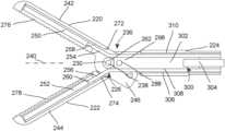
- FIGS. 16 - 19a further embodiment of a two-jaw surgical instrument having at least one light emitter and at least one light sensor is illustrated in FIGS. 16 - 19 . While the embodiment utilizes conductors in the form of leads or wires to connect the at least one light emitter and at least one light sensor to the remainder of the equipment, the shape and arrangement of the jaws according to the embodiment of FIGS. 16 - 18 may be utilized to permit the passage of flexible substrates into and out of the shaft of the surgical instrument as well.
- FIGS. 16 - 19illustrate a two-jaw surgical instrument including a first jaw 220 and a second jaw 222 .
- the first and second jaws 220 , 222are attached to a shaft 224 at a pivot or hinge 226 .
- each of the jaws 220 , 222has an opening or passage 228 , 230 that is aligned with openings or passages 232 , 234 in a distal end 236 of the shaft 224 .
- a pin or rod-shaped fastener 238is disposed through the openings or passages 228 , 230 , 232 , 234 to join the jaws 220 , 222 to the shaft 224 . While the ends of the fastener 238 are illustrated as extending past an outer surface of the shaft 224 in FIGS. 16 and 17 , the ends may terminate close to the outer surface according to other embodiments.
- the shaft 224has a longitudinal axis 240 that extends generally from the distal end 236 to a proximal end, where the handle or grip may be disposed.
- each jaw 220 , 222has a first, distal arm or end 242 , 244 that depends from the hinge 226 in a distal direction along the longitudinal axis 240 and a second, proximal arm or end 246 , 248 that depends from the hinge in a proximal direction along the longitudinal axis 240 .
- at least one light emitter 250is attached to the distal end 242 of the jaw 220
- at least one light sensor 252is attached to the distal end 244 of the jaw 222 .
- the surgical instrumentmay include one or more leads 254 , 256 to couple the at least one light emitter 250 and the at least one light sensor 252 to the remainder of the equipment, which may be located at the proximal end of the shaft 224 or may be even further removed from the distal end 236 of the shaft 224 .
- the lead 254 and the lead 256may actually include a plurality of leads or wires (e.g., six wires for the at least one light emitter 250 and six wires for the at least one light sensor 252 , which wires may be, for example, an insulated stranded wire or insulated solid core wire having a gauge of AWG 32 or 36 , preferably in ribbon cable form) that may or may not be assembled as a single unit, for ease of discussion, the leads 254 , 256 will be each be referred to in the singular.
- leads or wirese.g., six wires for the at least one light emitter 250 and six wires for the at least one light sensor 252 , which wires may be, for example, an insulated stranded wire or insulated solid core wire having a gauge of AWG 32 or 36 , preferably in ribbon cable form
- the lead 254is coupled at a distal end 258 to the at least one light emitter 250 , and the lead 256 is coupled to a distal end 260 of the at least one light sensor 252 , while the proximal ends of both leads 254 , 256 may be coupled to the remainder of the equipment.
- a spacer 262is introduced between inwardly facing or inner surfaces 264 , 266 of the jaws 220 , 222 .
- the spacer 262may have a first end 268 that abuts the surface 264 , and a second end 270 that abuts the surface 266 .
- the spacer 262is formed integrally (i.e., as one piece) with the jaw 222 , although this need not be the case according to other embodiments.
- the spacer 262defines clearances 272 , 274 for the leads 254 , 256 , as seen in FIGS. 16 and 17 .
- the clearances 272 , 274are volumes through which the leads 254 , 256 may exit/enter the shaft 224 without the other structures of the jaws 220 , 222 impinging on the leads 254 , 256 so as to crimp, pinch or crush the leads 254 , 256 .
- the clearances 272 , 274may be defined by the inner surfaces 264 , 266 of the jaws 220 , 222 and the spacer 262 .
- the clearances 272 , 274may have a cross-sectional area of 1.75 mm wide and 1.25 mm tall, for example.
- the surgical instrumentalso includes a mechanism for opening and closing the jaws 220 , 222 (i.e., moving surfaces 276 , 278 further apart and closer together). While an embodiment of such a mechanism is illustrated in FIGS. 18 and 19 , other mechanisms may be used to open and close the jaws 220 , 222 . For example, while the illustrated mechanism is positioned closer to the proximal end of the shaft 224 than the distal end 236 (relative to the hinge 226 ) in FIGS. 18 and 19 , other mechanisms operate the jaws 220 , 222 from the other side of the hinge 226 .
- the proximal ends 246 , 248 of the jaws 220 , 222each have a race or slot 280 , 282 that is formed through the ends 246 , 248 .
- the slots 280 , 282are arranged generally along a longitudinal axis 284 , 286 of the respective jaw 220 , 222 . As illustrated, the slots 280 , 282 may be disposed at a slight angle to the respective longitudinal axis 284 , 286 .
- a pin, rod or cam 288is received within the slots 280 , 282 , and may move along the slots 280 , 282 between a first end 290 , 292 of the slots 280 , 282 and a second end 294 , 296 of the slots 280 , 282 .
- the pin 288is attached to a distal end 298 of an actuator 300 , which may include a yoke 302 and a push rod 304 as illustrated.
- the proximal end of the actuator 300may be attached to a mechanism such as a scissors grip or a trigger grip, which may be disposed at the proximal end of the shaft 224 .
- the movement of the actuator 300 in a generally longitudinal direction to the right, with reference to the orientation illustrated in FIG. 19will cause the pin 288 to move from the first ends 290 , 292 to the second ends 294 , 296 of the slots 280 , 282 , which will cause the surfaces 276 , 278 to move toward each other (i.e., to close the jaws 220 , 222 ).
- the actuator 300may be biased (e.g., through the use of a spring or other resilient member) toward the left so that the jaws 220 , 222 are open by default.
- an inner surface 306 of the shaft 224 and an outer surface 308 of the actuator 300define a passage 310 between the distal end 236 and the proximal end of the shaft 224 .
- the passage 310may be annular, or may be some other shape.
- the passage 310may be discontinuous in certain embodiments, such that there is a discrete section aligned with clearance 272 and a discrete section aligned with clearance 274 .
- the passage 310permits the leads 254 , 256 to extend or depend between the distal end 236 and proximal end of the shaft 224 .
- the light emitter 120may include one or more elements, as referenced above.
- the light sensor 122may include a first light emitter 120 - 1 , a second light emitter 120 - 2 , and a third light emitter 120 - 3 . All of the light emitters may be adapted to emit light at a particular wavelength (e.g., 660 nm), or certain emitters may emit light at different wavelengths than other emitters. Each light emitter may be a light emitting diode, for example.
- the diodesmay be arranged in the form of a one-dimensional, two-dimensional or three-dimensional array.
- An example of a one-dimensional arraymay include disposing the diodes along a line in a single plane, while an example of a two-dimensional array may include disposing the diodes in a plurality of rows and columns in a single plane. Further example of a two-dimensional array may include disposing the diodes along a line on or in a curved surface.
- a three-dimensional arraymay include diodes disposed in more than one plane, such as in a plurality of rows and columns on or in a curved surface.
- the light sensor 122also may include one or more elements. Again, according to the embodiment illustrated in FIG. 6 , the light sensor 122 may include a first light sensor 122 - 1 , a second light sensor 122 - 2 , an n-th light sensor 122 - n , and so on. As was the case with the light emitters 120 - 1 , 120 - 2 , 120 - 3 , the light sensors 122 - 1 , 122 - 2 , 122 - 3 may be arranged in an array, and the discussion about the arrays above applied with equal force here.
- the array of light sensors 122may be referred to in the alternative as a linear array.
- the individual light sensors of the array 122may be disposed adjacent each other, or the light sensors may be spaced from each other. It may even be possible for the individual light sensors that define a row of light sensors to be separated from each other by light sensors that define a different row or column of the array.
- the arraymay comprise a charge coupled device (CCD), and in particular linear CCD imaging device comprising a plurality of pixels.
- a CMOS sensor arraymay be used.
- the arrangement of the light emitter 120 and the light sensor 122may vary relative to the reflectance-based embodiments of FIGS. 3 - 5 , it is equally true that the light emitter 120 and the light sensor 122 may involve a plurality of elements.
- the light emitter 120 and light sensor 122are disposed generally facing in a common direction (i.e., the direction of the tissue sample of interest). This does not require the emitter 120 and the sensor 122 to be generally disposed in a common plane, although this is preferred.
- the emitter 120 and sensor 122may be formed integrally (i.e., as one piece) with a surgical instrument 106 (see FIGS. 3 - 5 ), although other options are possible, as discussed below. In this manner, light emitted by the emitter 120 and scattered by the tissue of interest may be captured by the light sensor 122 .
- the spacing between the emitter 120 and the sensor 122may influence the light received by the sensor 122 .
- an ensemble of independent photonsreturn to the surface and reach the sensor 122 .
- Some of the detected photonstravel a short distance from the plane of the emitter and detector and exit at the site of the sensor 122 , while some photons travel farther into the tissue before exiting at the surface without being absorbed (photons that are absorbed cannot contribute to the photocurrent).
- Path length distributions and the penetration depth of photons that reach the sensor 122vary as a function of emitter-sensor separation, with maximum effective photon depth penetration values several times greater than the physical emitter-sensor separation. For example, it has been determined that a spacing between the emitter 120 and the sensor 122 of 5 mm may permit detection of vessels from 0 mm to 12 mm from the surface of the tissue.
- ACpulsatile
- detected photons traversing the shorter distancesare less exposed to the cycling blood of an artery at a greater depth below the tissue surface, and therefore survive with a more uniform likelihood between systolic and diastolic conditions.
- adjusting the angle of the emitter 120 and/or sensor 122may provide a similar effect. That is, similar to the way in which a change in the linear distance between the emitter 120 and the sensor 122 allows for the sampling of a different proportion of long-traveling photons at the surface sensor 122 , a variation in angle of the emitter 120 and/or sensor 122 can change the depth and the distance to which the photons travel before being sampled by the sensor 122 . Consequently, changes in the angle of the emitter and/or sensor are believed to permit the depth at which vessels can be detected by the instrument 106 to be varied.
- the emitter 120 and sensor 122may be disposed to be mounted in a fixed relationship to each other, or a moveable or adjustable relationship.
- FIGS. 3 and 4illustrate embodiments wherein emitter 120 and sensor 122 are at a fixed spacing relative to each other, and also have a fixed angular relationship between the emitter 120 and the sensor 122 .
- Such an embodimentwould permit the user to be confident that the vessels detected are within, for example, 12 mm from the working end 104 of the instrument 106 .
- the embodiment of FIG. 5has the sensor 122 mounted in a first jaw 180 of the instrument 106 and the emitter 120 mounted in a second jaw 182 of the instrument 106 .
- Such an embodimentwould permit the user to vary the depth of detection simply by varying the distance between the jaws 180 , 182 of the instrument 106 : with the jaws 180 , 182 closed, the user may probe for shallow vessels (i.e., vessels disposed within 12 mm of the tissue surface), while with the jaws 180 , 182 open, the user may probe for deeper vessels (i.e., vessels disposed greater than 12 mm below the tissue surface).
- shallow vesselsi.e., vessels disposed within 12 mm of the tissue surface
- the jaws 180 , 182 openthe user may probe for deeper vessels (i.e., vessels disposed greater than 12 mm below the tissue surface).
- the control structure for operating the jaws 180 , 182may include a mechanism for modifying the distance between the jaws 180 , 182 in a controlled fashion (e.g., in discrete increments) so that the user can determine the jaw spacing (and thus the detection depth) without visualization of the jaws 180 , 182 .
- the light emitter 120 of any of FIGS. 3 - 5may include one or more elements. According to such an embodiment, all of the elements may be adapted to emit light at a particular wavelength (e.g., 660 nm), or certain elements may emit light at different wavelengths than other elements. It is believed that a system with multiple light emitters 120 and/or multiple sensors 122 will increase the signal-to-noise ratio and the spatial resolution compared to a system containing a single emitter 120 and sensor 122 .
- the diodesmay be arranged in the form of a one-dimensional, two-dimensional or three-dimensional array.
- An example of a one-dimensional arraymay include disposing the diodes along a line in a single plane, while an example of a two-dimensional array may include disposing the diodes in a plurality of rows and columns in a single plane. Further example of a two-dimensional array may include disposing the diodes along a line on or in a curved surface.
- a three-dimensional arraymay include diodes disposed in more than one plane, such as in a plurality of rows and columns on or in a curved surface.
- the light sensor 122may include one or more individual elements. As was the case with the light emitter 120 , the elements of the light sensor 122 may be arranged in an array, and the discussion about the arrays above applied with equal force here.
- the light sensor 122may include a mechanism for physically excluding photons reaching the sensor 122 from a range of angles.
- This mechanismcan consist of a mask or grated layer to physically filter any photons that are not reaching the sensor 122 at a nearly perpendicular angle. It has been observed that the mean depth penetration of the photons leaving the emitter 120 is equal to just over half the distance of source-detector separation ( ⁇ 2.5 mm penetration for our 5 mm spacing). This mechanism will increase the proportion of long-traveling and deep penetrating photons that are received by the sensor 122 thus increasing the depth at which the vessels can be detected by the instrument.
- the system 100may include hardware and software in addition to the emitter 120 , sensor 122 , and controller 124 .
- a drive controllermay be provided to control the switching of the individual emitter elements.
- a multiplexermay be provided where more than one sensor 122 is included, which multiplexer may be coupled to the sensors 122 and to an amplifier.
- the controller 124may include filters and analog-to-digital conversion as may be required.
- the splitter 126 and the analyzer 128may be defined by one or more electrical circuit components.
- one or more processorsmay be programmed to perform the actions of the splitter 126 and the analyzer 128 .
- the splitter 126 and the analyzer 128may be defined in part by electrical circuit components and in part by a processor programmed to perform the actions of the splitter 126 and the analyzer 128 .
- the splitter 126may include or be defined by the processor programmed to separate the first pulsatile component from the second non-pulsatile component.
- the analyzer 128may include or be defined by the processor programmed to determine the presence of (or to quantify the size of, for example) the vessel V within the region 102 proximate to the working end 104 of the surgical instrument 106 based on the first pulsatile component.
- the instructions by which the processor is programmedmay be stored on a memory associated with the processor, which memory may include one or more tangible non-transitory computer readable memories, having computer executable instructions stored thereon, which when executed by the processor, may cause the one or more processors to carry out one or more actions.
- FIGS. 19 and 20illustrate embodiments of the surgical system 100 in combination with embodiments of a video system 320 , such as may be used conventionally during minimally invasive surgery or laparoscopic surgery, for example.
- the video system 320includes a video camera or other image capture device 322 , a video or other associated processor 324 , and a display 326 having a viewing screen 328 .
- the video camera 322is directed at the region 102 proximate the working ends 104 of two surgical instruments 106 .
- both of the surgical instruments 106are part of an embodiment of a surgical system 100 .
- the other elements of the surgical system 100are omitted for ease of illustration, although it will be noted that elements of the system 100 , such as the splitter 126 and the analyzer 128 , may be housed in the same physical housing as the video processor 324 .
- the signal from the video camera 322is passed to the display 326 via the video processor 324 , so that the surgeon or other member of the surgical team may view the region 102 as well as the working ends 104 of the surgical instruments 106 , which are typically inside the patient.
- FIG. 20illustrates another embodiment of a video system 320 that can be used in conjunction with an embodiment of the surgical system 100 .
- the video processor 324is not disposed in a housing separate from the video camera 322 ′, but is disposed in the same housing as the video camera 322 ′.
- the video processor 324may be disposed instead in the same housing as the remainder of the display 326 ′ as the display screen 328 ′. Otherwise, the discussion above relative to the embodiment of the video system 320 illustrated in FIG. 19 applies equally to the embodiment of the video system 320 illustrated in FIG. 20 .
- the system 100may include output devices such as illustrated in FIGS. 1 and 2 , which may incorporate elements of the system 320 .
- an alertmay be displayed on a video monitor 340 being used for the surgery (e.g., the display 326 , 326 ′ in FIGS. 19 and 20 ), or may cause an image on the monitor to change color or to flash, change size or otherwise change appearance.
- the auxiliary outputmay also be in the form of or include a speaker 342 that provides an auditory alarm.
- the auxiliary outputalso may be in the form of or may incorporate a safety lockout associated with the surgical instrument 106 that interrupts use of the instrument 106 .
- the lockoutcould prevent ligation or cauterization where the surgical instrument 106 is a thermal ligature device.
- the auxiliary outputalso may be in the form of a haptic feedback system, such as a vibrator 344 , which may be attached to or formed integral with a handle or handpiece of the surgical instrument 106 to provide a tactile indication or alarm.
- a haptic feedback systemsuch as a vibrator 344
- vibrator 344may be attached to or formed integral with a handle or handpiece of the surgical instrument 106 to provide a tactile indication or alarm.
- the surgical instrument 106may be a thermal ligature device in one embodiment.
- the surgical instrument 106may simply be a grasper or grasping forceps having opposing jaws.
- the surgical instrumentmay be other surgical instruments such as irrigators, surgical staplers, clip appliers, and robotic surgical systems, for example.
- the surgical instrumentmay have no other function that to carry the user interface and sensor and to place them within a surgical field. The illustration of a single embodiment is not intended to preclude the use of the system 100 with other surgical instruments or tools 106 .
Landscapes
- Health & Medical Sciences (AREA)
- Life Sciences & Earth Sciences (AREA)
- Surgery (AREA)
- Physics & Mathematics (AREA)
- Engineering & Computer Science (AREA)
- Veterinary Medicine (AREA)
- Biomedical Technology (AREA)
- Heart & Thoracic Surgery (AREA)
- Medical Informatics (AREA)
- Molecular Biology (AREA)
- Animal Behavior & Ethology (AREA)
- General Health & Medical Sciences (AREA)
- Public Health (AREA)
- Biophysics (AREA)
- Pathology (AREA)
- Nuclear Medicine, Radiotherapy & Molecular Imaging (AREA)
- Ophthalmology & Optometry (AREA)
- Vascular Medicine (AREA)
- Spectroscopy & Molecular Physics (AREA)
- Optics & Photonics (AREA)
- Surgical Instruments (AREA)
- Endoscopes (AREA)
Abstract
Description
Claims (9)
Priority Applications (1)
| Application Number | Priority Date | Filing Date | Title |
|---|---|---|---|
| US16/955,675US11696777B2 (en) | 2017-12-22 | 2018-12-21 | Compact system used to determine tissue or artifact characteristics |
Applications Claiming Priority (3)
| Application Number | Priority Date | Filing Date | Title |
|---|---|---|---|
| US201762609746P | 2017-12-22 | 2017-12-22 | |
| PCT/US2018/067069WO2019126633A1 (en) | 2017-12-22 | 2018-12-21 | A compact system used to determine tissue or artifact characteristics |
| US16/955,675US11696777B2 (en) | 2017-12-22 | 2018-12-21 | Compact system used to determine tissue or artifact characteristics |
Publications (2)
| Publication Number | Publication Date |
|---|---|
| US20210068856A1 US20210068856A1 (en) | 2021-03-11 |
| US11696777B2true US11696777B2 (en) | 2023-07-11 |
Family
ID=65324528
Family Applications (1)
| Application Number | Title | Priority Date | Filing Date |
|---|---|---|---|
| US16/955,675ActiveUS11696777B2 (en) | 2017-12-22 | 2018-12-21 | Compact system used to determine tissue or artifact characteristics |
Country Status (5)
| Country | Link |
|---|---|
| US (1) | US11696777B2 (en) |
| EP (1) | EP3727140B1 (en) |
| JP (1) | JP7313353B2 (en) |
| ES (1) | ES2965921T3 (en) |
| WO (1) | WO2019126633A1 (en) |
Families Citing this family (7)
| Publication number | Priority date | Publication date | Assignee | Title |
|---|---|---|---|---|
| US11399898B2 (en) | 2012-03-06 | 2022-08-02 | Briteseed, Llc | User interface for a system used to determine tissue or artifact characteristics |
| EP4026489B1 (en) | 2016-08-30 | 2025-07-30 | Briteseed, LLC | System for determining vessel size with angular distortion compensation |
| US11723600B2 (en) | 2017-09-05 | 2023-08-15 | Briteseed, Llc | System and method used to determine tissue and/or artifact characteristics |
| EP3902471B1 (en) | 2018-12-30 | 2024-09-18 | Briteseed, LLC | A system used to detect or differentiate tissue or an artifact |
| NL2025324B1 (en)* | 2020-04-09 | 2021-10-26 | Academisch Ziekenhuis Leiden | A Surgical Tool, System and Method for Tissue Characterisation |
| JP2025519340A (en) | 2022-05-11 | 2025-06-26 | ブライトシード・エルエルシー | Graphical interface for the system used to determine tissue properties |
| WO2025064423A1 (en) | 2023-09-21 | 2025-03-27 | Briteseed, Llc | System and method for excitation and detection of fluorescent indicators |
Citations (101)
| Publication number | Priority date | Publication date | Assignee | Title |
|---|---|---|---|---|
| GB1445678A (en) | 1972-06-30 | 1976-08-11 | Secr Social Service Brit | Clinical device comprising a catheter |
| US5129400A (en) | 1989-04-10 | 1992-07-14 | Kowa Company Ltd. | Ophthalmological measurement method and apparatus |
| US5259761A (en) | 1990-08-06 | 1993-11-09 | Jenifer M. Schnettler | Tooth vitality probe and process |
| JPH07255735A (en) | 1994-03-17 | 1995-10-09 | Terumo Corp | Surgical appliance |
| JPH105245A (en) | 1996-06-25 | 1998-01-13 | Shimadzu Corp | Surgical operation support device |
| US5762609A (en) | 1992-09-14 | 1998-06-09 | Sextant Medical Corporation | Device and method for analysis of surgical tissue interventions |
| US5769791A (en) | 1992-09-14 | 1998-06-23 | Sextant Medical Corporation | Tissue interrogating device and methods |
| WO1998027865A1 (en) | 1996-12-23 | 1998-07-02 | Benaron David A | Device and method for classification of tissue |
| US6178340B1 (en) | 1998-08-24 | 2001-01-23 | Eduardo Svetliza | Three-dimensional infrared imager for subcutaneous puncture and study of vascular network |
| WO2001060427A2 (en) | 2000-02-15 | 2001-08-23 | Transvascular, Inc. | Sterility barriers for insertion of non-sterile apparatus into catheters or other medical devices |
| US6374128B1 (en) | 1998-11-20 | 2002-04-16 | Fuji Photo Film Co., Ltd. | Blood vessel imaging system |
| US20020169381A1 (en) | 2000-04-18 | 2002-11-14 | Asada Haruhiko H. | Photoplethysmograph signal-to-noise line enhancement |
| JP2003019116A (en) | 2001-07-05 | 2003-01-21 | Canon Inc | Ophthalmic measurement device |
| US20030036685A1 (en) | 2000-04-27 | 2003-02-20 | Vitalsines International, Inc. | Physiological signal monitoring system |
| US20030036751A1 (en) | 2001-05-30 | 2003-02-20 | Anderson R. Rox | Apparatus and method for laser treatment with spectroscopic feedback |
| WO2003039326A2 (en) | 2001-11-07 | 2003-05-15 | Mills Alexander K | Method for noninvasive continuous determination of physiologic characteristics |
| US6569104B2 (en) | 1998-07-16 | 2003-05-27 | Canon Kabushiki Kaisha | Blood vessel detecting apparatus |
| US20030120306A1 (en) | 2000-04-21 | 2003-06-26 | Vascular Control System | Method and apparatus for the detection and occlusion of blood vessels |
| US20040044363A1 (en)* | 2002-08-27 | 2004-03-04 | Fowler David N. | Apparatus and method for removing a clip |
| WO2004030527A1 (en) | 2002-10-03 | 2004-04-15 | Etview Ltd. | Tube for inspecting internal organs of a body |
| US20040111085A1 (en) | 1999-07-20 | 2004-06-10 | Singh Ajoy Inder | Method and apparatus for arterial ablation |
| US20050021027A1 (en) | 2003-05-15 | 2005-01-27 | Chelsea Shields | Tissue sealer with non-conductive variable stop members and method of sealing tissue |
| JP2005058553A (en) | 2003-08-18 | 2005-03-10 | Olympus Corp | Instrument for medical treatment |
| US20050143662A1 (en) | 2000-05-03 | 2005-06-30 | Rocky Mountain Biosystems, Inc. | Optical imaging of subsurface anatomical structures and biomolecules |
| US6922577B2 (en) | 2002-02-15 | 2005-07-26 | Denso Corporation | Optical measuring device having d.c. component elimination |
| US20050180620A1 (en) | 2002-05-09 | 2005-08-18 | Kiyoaki Takiguchi | Method of detecting biological pattern, biological pattern detector, method of biological certificate and biological certificate apparatus |
| WO2005091978A2 (en) | 2004-03-22 | 2005-10-06 | Vanderbilt University | System and methods for surgical instrument disablement via image-guided position feedback |
| US20060020212A1 (en) | 2004-07-26 | 2006-01-26 | Tianning Xu | Portable vein locating device |
| US7006861B2 (en) | 1995-06-07 | 2006-02-28 | Board Of Trustees Of The University Of Arkansas | Method and apparatus for detecting electro-magnetic reflection from biological tissue |
| US20060052850A1 (en) | 2004-09-03 | 2006-03-09 | Darmos George P | Hybrid cannula/electrode medical device and method |
| US20060100523A1 (en) | 2004-11-08 | 2006-05-11 | Ogle John S | Noninvasive blood vessel location device and method |
| US20060155194A1 (en) | 2005-01-13 | 2006-07-13 | Ronald Marcotte | Method for detecting occlusions and leakages in subcutaneous blood vessels |
| US7112201B2 (en) | 2001-10-22 | 2006-09-26 | Surgrx Inc. | Electrosurgical instrument and method of use |
| US20070038118A1 (en) | 2005-08-10 | 2007-02-15 | Depue Marshall Thomas | Subcutaneous tissue imager |
| US7235072B2 (en) | 2003-02-20 | 2007-06-26 | Sherwood Services Ag | Motion detector for controlling electrosurgical output |
| EP1870034A1 (en) | 2006-06-22 | 2007-12-26 | Tyco Healthcare Group Lp | Tissue vitality comparator with light pipe with fiber optic imaging bundle |
| WO2008082992A1 (en) | 2007-01-04 | 2008-07-10 | Boston Scientific Limited | Locating and occluding vessels |
| US20090018414A1 (en) | 2007-03-23 | 2009-01-15 | Mehrdad Toofan | Subcutanous Blood Vessels Imaging System |
| US20090054908A1 (en) | 2005-04-15 | 2009-02-26 | Jason Matthew Zand | Surgical instruments with sensors for detecting tissue properties, and system using such instruments |
| US7515265B2 (en) | 2005-04-28 | 2009-04-07 | Research Foundation Of The City University Of New York | Imaging systems and methods to improve backscattering imaging using circular polarization memory |
| WO2009144653A2 (en) | 2008-05-30 | 2009-12-03 | Koninklijke Philips Electronics N.V. | Needle with integrated photon detector |
| JP2010081972A (en) | 2008-09-29 | 2010-04-15 | Olympus Corp | Surgical treatment system and surgical treatment instrument |
| US7740591B1 (en) | 2003-12-01 | 2010-06-22 | Ric Investments, Llc | Apparatus and method for monitoring pressure related changes in the extra-thoracic arterial circulatory system |
| US7749217B2 (en) | 2002-05-06 | 2010-07-06 | Covidien Ag | Method and system for optically detecting blood and controlling a generator during electrosurgery |
| US20100222786A1 (en) | 2003-02-21 | 2010-09-02 | Kassab Ghassan S | Devices, systems, and methods for removing targeted lesions from vessels |
| US20100249763A1 (en) | 2007-05-14 | 2010-09-30 | The Regents Of The University Of Colorado | Laser Tissue Fusion of Septal Membranes |
| US20110021925A1 (en) | 2006-06-29 | 2011-01-27 | Fred Wood | Mounted vein contrast enchancer |
| WO2011013132A1 (en) | 2009-07-30 | 2011-02-03 | Oxitone Medical Ltd. | Photoplethysmography device and method |
| US7904138B2 (en) | 2006-01-10 | 2011-03-08 | Accuvein Llc | Micro vein enhancer |
| US7983738B2 (en) | 2006-01-10 | 2011-07-19 | Accuvein, Llc | Three dimensional imaging of veins |
| EP2353534A1 (en) | 2010-01-29 | 2011-08-10 | Tyco Healthcare Group, LP | Surgical forceps capable of adjusting seal plate width based on vessel size |
| US20110245685A1 (en) | 2010-04-02 | 2011-10-06 | Seiko Epson Corporation | Blood vessel display device |
| US8058771B2 (en) | 2008-08-06 | 2011-11-15 | Ethicon Endo-Surgery, Inc. | Ultrasonic device for cutting and coagulating with stepped output |
| US20120016362A1 (en) | 2002-04-25 | 2012-01-19 | Tyco Healthcare Group Lp | Surgical Instrument Including MEMS Devices |
| US8118206B2 (en) | 2008-03-15 | 2012-02-21 | Surgisense Corporation | Sensing adjunct for surgical staplers |
| US20120046555A1 (en) | 2009-03-13 | 2012-02-23 | Tetsuro Takamatsu | Body tissue imaging using raman scattering light |
| US8123745B2 (en) | 2007-06-29 | 2012-02-28 | Biosense Webster, Inc. | Ablation catheter with optically transparent, electrically conductive tip |
| US20120143182A1 (en) | 2010-12-07 | 2012-06-07 | Immersion Corporation | Electrosurgical sealing tool having haptic feedback |
| US20120172842A1 (en) | 2010-12-30 | 2012-07-05 | Ran Sela | Method of assembling a positioning sensor and associated wiring on a medical tool |
| US8255040B2 (en) | 2006-06-29 | 2012-08-28 | Accuvein, Llc | Micro vein enhancer |
| WO2012158774A1 (en) | 2011-05-16 | 2012-11-22 | Tyco Healthcare Group Lp | Optical recognition of tissue and vessels |
| US8380291B2 (en) | 2006-06-29 | 2013-02-19 | Accuvein Inc. | Scanned laser vein contrast enhancer |
| US8417306B2 (en) | 2007-02-16 | 2013-04-09 | Mespere Lifesciences Inc. | Method and device for measuring parameters of cardiac function |
| US8463364B2 (en) | 2009-07-22 | 2013-06-11 | Accuvein Inc. | Vein scanner |
| US8467857B2 (en) | 2008-04-11 | 2013-06-18 | Seoul National University R & Db Foundation | Hypodermic vein detection imaging apparatus based on infrared optical system |
| US8483819B2 (en) | 2009-12-17 | 2013-07-09 | Korea Advanced Institute Of Science And Technology | Modulator of vascular permeability using pulsed laser and method for modulating vascular permeability using the same |
| US8483805B2 (en) | 2011-01-24 | 2013-07-09 | Act Medical Service Co., Ltd. | Vessel pulse wave measurement system conducting vessel pulse wave measurement by obtaining pulsation waveform of blood vessel |
| US8489178B2 (en) | 2006-06-29 | 2013-07-16 | Accuvein Inc. | Enhanced laser vein contrast enhancer with projection of analyzed vein data |
| US20130226013A1 (en) | 2007-11-09 | 2013-08-29 | Western Clinical Engineering, Ltd. | Method for Measuring Tourniquet Limb Occlusion Pressure |
| WO2013134411A1 (en) | 2012-03-06 | 2013-09-12 | Briteseed, Llc | Surgical tool with integrated sensor |
| US20130267874A1 (en) | 2012-04-09 | 2013-10-10 | Amy L. Marcotte | Surgical instrument with nerve detection feature |
| US8586924B2 (en) | 2010-09-13 | 2013-11-19 | Lawrence Livermore National Security, Llc | Enhancement of the visibility of objects located below the surface of a scattering medium |
| US8649848B2 (en) | 2006-03-28 | 2014-02-11 | The United States Of America, As Represented By The Secretary Of The Air Force | Synchronization of illumination source and sensor for improved visualization of subcutaneous structures |
| US8649568B2 (en) | 2007-07-20 | 2014-02-11 | Sony Corporation | Vein authentication apparatus, imaging apparatus for vein authentication, and vein illuminating method |
| US8682418B2 (en) | 2011-02-01 | 2014-03-25 | Olympus Medical Systems Corp. | Diagnosis supporting apparatus and control method of diagnosis supporting apparatus |
| US20140086459A1 (en) | 2012-09-27 | 2014-03-27 | Truelight Corporation | Biometric Authentication Device and Method |
| US20140100455A1 (en) | 2006-01-10 | 2014-04-10 | Ron Goldman | Scanned Laser Vein Contrast Enhancer |
| US20140155753A1 (en) | 2011-08-01 | 2014-06-05 | James E. McGuire, Jr. | Disposable light source for enhanced visualization of subcutaneous structures |
| US8792967B2 (en) | 2004-12-28 | 2014-07-29 | Sony Corporation | Bioimaging apparatus |
| US20140236019A1 (en) | 2011-08-14 | 2014-08-21 | Uzi Rahum | Device, system and method for blood vessel imaging and marking |
| US20140277106A1 (en) | 2013-03-18 | 2014-09-18 | Intuitive Surgical Operations, Inc. | Surgical instrument drive element, and related devices, systems, and methods |
| US20140276088A1 (en) | 2013-03-15 | 2014-09-18 | Steven H. Drucker | Illumination Optics for a Visible or Infrared Based Apparatus and Methods for Viewing or Imaging Blood Vessels |
| US20140313482A1 (en) | 2009-11-30 | 2014-10-23 | The Board Of Trustees Of The University Of Illinois | Assessment of microvascular circulation |
| WO2014194317A1 (en) | 2013-05-31 | 2014-12-04 | Covidien Lp | Surgical device with an end-effector assembly and system for monitoring of tissue during a surgical procedure |
| US20150011896A1 (en) | 2012-01-19 | 2015-01-08 | Technion Research & Development Foundation Limited | Vessel imaging system and method |
| US20150051460A1 (en) | 2012-04-04 | 2015-02-19 | Noopur Saxena | System and method for locating blood vessels and analysing blood |
| WO2015148504A1 (en) | 2014-03-25 | 2015-10-01 | Briteseed Llc | Vessel detector and method of detection |
| WO2016134330A1 (en) | 2015-02-19 | 2016-08-25 | Briteseed Llc | System and method for determining vessel size and/or edge |
| WO2016134327A1 (en) | 2015-02-19 | 2016-08-25 | Briteseed Llc | System for determining vessel size using light absorption |
| US9526921B2 (en) | 2010-11-05 | 2016-12-27 | Ethicon Endo-Surgery, Llc | User feedback through end effector of surgical instrument |
| US20170079740A1 (en) | 2014-02-21 | 2017-03-23 | Covidien Lp | Instrument for optically detecting tissue attributes |
| WO2017062720A1 (en) | 2015-10-08 | 2017-04-13 | Briteseed Llc | System and method for determining vessel size |
| EP3181040A1 (en) | 2015-12-18 | 2017-06-21 | Covidien LP | Surgical instruments including sensors |
| WO2017139642A1 (en) | 2016-02-13 | 2017-08-17 | Briteseed Llc | System and method for electrical coupling of a surgical system or part thereof |
| WO2017139624A1 (en) | 2016-02-12 | 2017-08-17 | Briteseed Llc | Determination of the presence of a vessel within a region proximate to a working end of a surgical instrument |
| US20170367772A1 (en) | 2012-03-06 | 2017-12-28 | Briteseed, Llc | User Interface for a System Used to Determine Tissue or Artifact Characteristics |
| WO2018044722A1 (en) | 2016-08-30 | 2018-03-08 | Briteseed Llc | System and method for determining vessel size with angular distortion compensation |
| WO2019050928A1 (en) | 2017-09-05 | 2019-03-14 | Briteseed, Llc | System and method used to determine tissue and/or artifact characteristics |
| WO2019143965A1 (en) | 2018-01-18 | 2019-07-25 | Briteseed, Llc | System and method for detecting and/or determining characteristics of tissue |
| WO2020041203A1 (en) | 2018-08-20 | 2020-02-27 | Briteseed, Llc | A system and method with applied stimulation used to detect or differentiate tissue or artifact |
| WO2020142394A1 (en) | 2018-12-30 | 2020-07-09 | Briteseed, Llc | A system and method used to detect or differentiate tissue or an artifact |
- 2018
- 2018-12-21USUS16/955,675patent/US11696777B2/enactiveActive
- 2018-12-21EPEP18845391.4Apatent/EP3727140B1/enactiveActive
- 2018-12-21ESES18845391Tpatent/ES2965921T3/enactiveActive
- 2018-12-21JPJP2020534481Apatent/JP7313353B2/enactiveActive
- 2018-12-21WOPCT/US2018/067069patent/WO2019126633A1/ennot_activeCeased
Patent Citations (135)
| Publication number | Priority date | Publication date | Assignee | Title |
|---|---|---|---|---|
| GB1445678A (en) | 1972-06-30 | 1976-08-11 | Secr Social Service Brit | Clinical device comprising a catheter |
| US5129400A (en) | 1989-04-10 | 1992-07-14 | Kowa Company Ltd. | Ophthalmological measurement method and apparatus |
| US5259761A (en) | 1990-08-06 | 1993-11-09 | Jenifer M. Schnettler | Tooth vitality probe and process |
| US5785658A (en) | 1992-09-14 | 1998-07-28 | Sexant Medical Corporation | In vivo tissue analysis methods and apparatus |
| US5762609A (en) | 1992-09-14 | 1998-06-09 | Sextant Medical Corporation | Device and method for analysis of surgical tissue interventions |
| US5769791A (en) | 1992-09-14 | 1998-06-23 | Sextant Medical Corporation | Tissue interrogating device and methods |
| US5772597A (en) | 1992-09-14 | 1998-06-30 | Sextant Medical Corporation | Surgical tool end effector |
| US5807261A (en) | 1992-09-14 | 1998-09-15 | Sextant Medical Corporation | Noninvasive system for characterizing tissue in vivo |
| US6594518B1 (en) | 1993-02-26 | 2003-07-15 | David A. Benaron | Device and method for classification of tissue |
| US5987346A (en) | 1993-02-26 | 1999-11-16 | Benaron; David A. | Device and method for classification of tissue |
| JPH07255735A (en) | 1994-03-17 | 1995-10-09 | Terumo Corp | Surgical appliance |
| US7006861B2 (en) | 1995-06-07 | 2006-02-28 | Board Of Trustees Of The University Of Arkansas | Method and apparatus for detecting electro-magnetic reflection from biological tissue |
| JPH105245A (en) | 1996-06-25 | 1998-01-13 | Shimadzu Corp | Surgical operation support device |
| WO1998027865A1 (en) | 1996-12-23 | 1998-07-02 | Benaron David A | Device and method for classification of tissue |
| US6569104B2 (en) | 1998-07-16 | 2003-05-27 | Canon Kabushiki Kaisha | Blood vessel detecting apparatus |
| US6178340B1 (en) | 1998-08-24 | 2001-01-23 | Eduardo Svetliza | Three-dimensional infrared imager for subcutaneous puncture and study of vascular network |
| US6374128B1 (en) | 1998-11-20 | 2002-04-16 | Fuji Photo Film Co., Ltd. | Blood vessel imaging system |
| US20040111085A1 (en) | 1999-07-20 | 2004-06-10 | Singh Ajoy Inder | Method and apparatus for arterial ablation |
| WO2001060427A2 (en) | 2000-02-15 | 2001-08-23 | Transvascular, Inc. | Sterility barriers for insertion of non-sterile apparatus into catheters or other medical devices |
| US20020169381A1 (en) | 2000-04-18 | 2002-11-14 | Asada Haruhiko H. | Photoplethysmograph signal-to-noise line enhancement |
| US20030120306A1 (en) | 2000-04-21 | 2003-06-26 | Vascular Control System | Method and apparatus for the detection and occlusion of blood vessels |
| US20030036685A1 (en) | 2000-04-27 | 2003-02-20 | Vitalsines International, Inc. | Physiological signal monitoring system |
| US20050143662A1 (en) | 2000-05-03 | 2005-06-30 | Rocky Mountain Biosystems, Inc. | Optical imaging of subsurface anatomical structures and biomolecules |
| US20030036751A1 (en) | 2001-05-30 | 2003-02-20 | Anderson R. Rox | Apparatus and method for laser treatment with spectroscopic feedback |
| JP2003019116A (en) | 2001-07-05 | 2003-01-21 | Canon Inc | Ophthalmic measurement device |
| US7112201B2 (en) | 2001-10-22 | 2006-09-26 | Surgrx Inc. | Electrosurgical instrument and method of use |
| WO2003039326A2 (en) | 2001-11-07 | 2003-05-15 | Mills Alexander K | Method for noninvasive continuous determination of physiologic characteristics |
| US6922577B2 (en) | 2002-02-15 | 2005-07-26 | Denso Corporation | Optical measuring device having d.c. component elimination |
| US20120016362A1 (en) | 2002-04-25 | 2012-01-19 | Tyco Healthcare Group Lp | Surgical Instrument Including MEMS Devices |
| US7749217B2 (en) | 2002-05-06 | 2010-07-06 | Covidien Ag | Method and system for optically detecting blood and controlling a generator during electrosurgery |
| US20050180620A1 (en) | 2002-05-09 | 2005-08-18 | Kiyoaki Takiguchi | Method of detecting biological pattern, biological pattern detector, method of biological certificate and biological certificate apparatus |
| US20040044363A1 (en)* | 2002-08-27 | 2004-03-04 | Fowler David N. | Apparatus and method for removing a clip |
| WO2004030527A1 (en) | 2002-10-03 | 2004-04-15 | Etview Ltd. | Tube for inspecting internal organs of a body |
| US7235072B2 (en) | 2003-02-20 | 2007-06-26 | Sherwood Services Ag | Motion detector for controlling electrosurgical output |
| US20100222786A1 (en) | 2003-02-21 | 2010-09-02 | Kassab Ghassan S | Devices, systems, and methods for removing targeted lesions from vessels |
| JP2010264260A (en) | 2003-05-15 | 2010-11-25 | Covidien Ag | Tissue sealer with non-conductive variable stop member and method for sealing tissue |
| US20050021027A1 (en) | 2003-05-15 | 2005-01-27 | Chelsea Shields | Tissue sealer with non-conductive variable stop members and method of sealing tissue |
| JP2005058553A (en) | 2003-08-18 | 2005-03-10 | Olympus Corp | Instrument for medical treatment |
| US7740591B1 (en) | 2003-12-01 | 2010-06-22 | Ric Investments, Llc | Apparatus and method for monitoring pressure related changes in the extra-thoracic arterial circulatory system |
| WO2005091978A2 (en) | 2004-03-22 | 2005-10-06 | Vanderbilt University | System and methods for surgical instrument disablement via image-guided position feedback |
| US20060020212A1 (en) | 2004-07-26 | 2006-01-26 | Tianning Xu | Portable vein locating device |
| US20060052850A1 (en) | 2004-09-03 | 2006-03-09 | Darmos George P | Hybrid cannula/electrode medical device and method |
| US20060100523A1 (en) | 2004-11-08 | 2006-05-11 | Ogle John S | Noninvasive blood vessel location device and method |
| US8792967B2 (en) | 2004-12-28 | 2014-07-29 | Sony Corporation | Bioimaging apparatus |
| US20060155194A1 (en) | 2005-01-13 | 2006-07-13 | Ronald Marcotte | Method for detecting occlusions and leakages in subcutaneous blood vessels |
| US20090054908A1 (en) | 2005-04-15 | 2009-02-26 | Jason Matthew Zand | Surgical instruments with sensors for detecting tissue properties, and system using such instruments |
| US7515265B2 (en) | 2005-04-28 | 2009-04-07 | Research Foundation Of The City University Of New York | Imaging systems and methods to improve backscattering imaging using circular polarization memory |
| US20070038118A1 (en) | 2005-08-10 | 2007-02-15 | Depue Marshall Thomas | Subcutaneous tissue imager |
| US7983738B2 (en) | 2006-01-10 | 2011-07-19 | Accuvein, Llc | Three dimensional imaging of veins |
| US7904138B2 (en) | 2006-01-10 | 2011-03-08 | Accuvein Llc | Micro vein enhancer |
| US8150500B2 (en) | 2006-01-10 | 2012-04-03 | Accuvein Inc. | Micro vein enhancer |
| US8712498B2 (en) | 2006-01-10 | 2014-04-29 | Accuvein Inc. | Micro vein enhancer |
| US8818493B2 (en) | 2006-01-10 | 2014-08-26 | Accuvein, Inc. | Three-dimensional imaging of veins |
| US20140100455A1 (en) | 2006-01-10 | 2014-04-10 | Ron Goldman | Scanned Laser Vein Contrast Enhancer |
| US8073531B2 (en) | 2006-01-10 | 2011-12-06 | Accuvein, Llc | Micro vein enhancer |
| US8295904B2 (en) | 2006-01-10 | 2012-10-23 | Accuvein, Llc | Micro vein enhancer |
| US8750970B2 (en) | 2006-01-10 | 2014-06-10 | Accu Vein, Inc. | Micro vein enhancer |
| US8478386B2 (en) | 2006-01-10 | 2013-07-02 | Accuvein Inc. | Practitioner-mounted micro vein enhancer |
| US20130102905A1 (en) | 2006-01-10 | 2013-04-25 | Ron Goldman | Micro Vein Enhancer |
| US8649848B2 (en) | 2006-03-28 | 2014-02-11 | The United States Of America, As Represented By The Secretary Of The Air Force | Synchronization of illumination source and sensor for improved visualization of subcutaneous structures |
| US20070299468A1 (en)* | 2006-06-22 | 2007-12-27 | Viola Frank J | Tissue vitality comparator with light pipe with fiber optic imaging bundle |
| EP1870034A1 (en) | 2006-06-22 | 2007-12-26 | Tyco Healthcare Group Lp | Tissue vitality comparator with light pipe with fiber optic imaging bundle |
| US8838210B2 (en) | 2006-06-29 | 2014-09-16 | AccuView, Inc. | Scanned laser vein contrast enhancer using a single laser |
| US8380291B2 (en) | 2006-06-29 | 2013-02-19 | Accuvein Inc. | Scanned laser vein contrast enhancer |
| US20110021925A1 (en) | 2006-06-29 | 2011-01-27 | Fred Wood | Mounted vein contrast enchancer |
| US8706200B2 (en) | 2006-06-29 | 2014-04-22 | Accuvein, Inc. | Scanned laser vein contrast enhancer |
| US8489178B2 (en) | 2006-06-29 | 2013-07-16 | Accuvein Inc. | Enhanced laser vein contrast enhancer with projection of analyzed vein data |
| US8244333B2 (en) | 2006-06-29 | 2012-08-14 | Accuvein, Llc | Scanned laser vein contrast enhancer |
| US8255040B2 (en) | 2006-06-29 | 2012-08-28 | Accuvein, Llc | Micro vein enhancer |
| US20140194751A1 (en) | 2006-06-29 | 2014-07-10 | Ron Goldman | Scanned Laser Vein Contrast Enhancer Using One Laser for a Detection Mode and a Display Mode |
| US8391960B2 (en) | 2006-06-29 | 2013-03-05 | Accuvein Inc. | Scanned laser vein contrast enhancer |
| WO2008082992A1 (en) | 2007-01-04 | 2008-07-10 | Boston Scientific Limited | Locating and occluding vessels |
| US8417306B2 (en) | 2007-02-16 | 2013-04-09 | Mespere Lifesciences Inc. | Method and device for measuring parameters of cardiac function |
| US20090018414A1 (en) | 2007-03-23 | 2009-01-15 | Mehrdad Toofan | Subcutanous Blood Vessels Imaging System |
| US20100249763A1 (en) | 2007-05-14 | 2010-09-30 | The Regents Of The University Of Colorado | Laser Tissue Fusion of Septal Membranes |
| US8123745B2 (en) | 2007-06-29 | 2012-02-28 | Biosense Webster, Inc. | Ablation catheter with optically transparent, electrically conductive tip |
| US8649568B2 (en) | 2007-07-20 | 2014-02-11 | Sony Corporation | Vein authentication apparatus, imaging apparatus for vein authentication, and vein illuminating method |
| US20130226013A1 (en) | 2007-11-09 | 2013-08-29 | Western Clinical Engineering, Ltd. | Method for Measuring Tourniquet Limb Occlusion Pressure |
| US8118206B2 (en) | 2008-03-15 | 2012-02-21 | Surgisense Corporation | Sensing adjunct for surgical staplers |
| US8467857B2 (en) | 2008-04-11 | 2013-06-18 | Seoul National University R & Db Foundation | Hypodermic vein detection imaging apparatus based on infrared optical system |
| WO2009144653A2 (en) | 2008-05-30 | 2009-12-03 | Koninklijke Philips Electronics N.V. | Needle with integrated photon detector |
| US8058771B2 (en) | 2008-08-06 | 2011-11-15 | Ethicon Endo-Surgery, Inc. | Ultrasonic device for cutting and coagulating with stepped output |
| JP2010081972A (en) | 2008-09-29 | 2010-04-15 | Olympus Corp | Surgical treatment system and surgical treatment instrument |
| US20120046555A1 (en) | 2009-03-13 | 2012-02-23 | Tetsuro Takamatsu | Body tissue imaging using raman scattering light |
| US8463364B2 (en) | 2009-07-22 | 2013-06-11 | Accuvein Inc. | Vein scanner |
| WO2011013132A1 (en) | 2009-07-30 | 2011-02-03 | Oxitone Medical Ltd. | Photoplethysmography device and method |
| US20140313482A1 (en) | 2009-11-30 | 2014-10-23 | The Board Of Trustees Of The University Of Illinois | Assessment of microvascular circulation |
| US8483819B2 (en) | 2009-12-17 | 2013-07-09 | Korea Advanced Institute Of Science And Technology | Modulator of vascular permeability using pulsed laser and method for modulating vascular permeability using the same |
| EP2353534A1 (en) | 2010-01-29 | 2011-08-10 | Tyco Healthcare Group, LP | Surgical forceps capable of adjusting seal plate width based on vessel size |
| US20110245685A1 (en) | 2010-04-02 | 2011-10-06 | Seiko Epson Corporation | Blood vessel display device |
| US8586924B2 (en) | 2010-09-13 | 2013-11-19 | Lawrence Livermore National Security, Llc | Enhancement of the visibility of objects located below the surface of a scattering medium |
| US9526921B2 (en) | 2010-11-05 | 2016-12-27 | Ethicon Endo-Surgery, Llc | User feedback through end effector of surgical instrument |
| US20120143182A1 (en) | 2010-12-07 | 2012-06-07 | Immersion Corporation | Electrosurgical sealing tool having haptic feedback |
| US20120172842A1 (en) | 2010-12-30 | 2012-07-05 | Ran Sela | Method of assembling a positioning sensor and associated wiring on a medical tool |
| US8483805B2 (en) | 2011-01-24 | 2013-07-09 | Act Medical Service Co., Ltd. | Vessel pulse wave measurement system conducting vessel pulse wave measurement by obtaining pulsation waveform of blood vessel |
| US8682418B2 (en) | 2011-02-01 | 2014-03-25 | Olympus Medical Systems Corp. | Diagnosis supporting apparatus and control method of diagnosis supporting apparatus |
| WO2012158774A1 (en) | 2011-05-16 | 2012-11-22 | Tyco Healthcare Group Lp | Optical recognition of tissue and vessels |
| US20120296205A1 (en) | 2011-05-16 | 2012-11-22 | Tyco Healthcare Group Lp | Optical Recognition of Tissue and Vessels |
| US20140155753A1 (en) | 2011-08-01 | 2014-06-05 | James E. McGuire, Jr. | Disposable light source for enhanced visualization of subcutaneous structures |
| US20140236019A1 (en) | 2011-08-14 | 2014-08-21 | Uzi Rahum | Device, system and method for blood vessel imaging and marking |
| US20150011896A1 (en) | 2012-01-19 | 2015-01-08 | Technion Research & Development Foundation Limited | Vessel imaging system and method |
| US20150066000A1 (en) | 2012-03-06 | 2015-03-05 | Briteseed Llc | Surgical Tool With Integrated Sensor |
| US20170367772A1 (en) | 2012-03-06 | 2017-12-28 | Briteseed, Llc | User Interface for a System Used to Determine Tissue or Artifact Characteristics |
| WO2013134411A1 (en) | 2012-03-06 | 2013-09-12 | Briteseed, Llc | Surgical tool with integrated sensor |
| US20150051460A1 (en) | 2012-04-04 | 2015-02-19 | Noopur Saxena | System and method for locating blood vessels and analysing blood |
| US20130267874A1 (en) | 2012-04-09 | 2013-10-10 | Amy L. Marcotte | Surgical instrument with nerve detection feature |
| US20140086459A1 (en) | 2012-09-27 | 2014-03-27 | Truelight Corporation | Biometric Authentication Device and Method |
| US20140276088A1 (en) | 2013-03-15 | 2014-09-18 | Steven H. Drucker | Illumination Optics for a Visible or Infrared Based Apparatus and Methods for Viewing or Imaging Blood Vessels |
| JP2016518171A (en) | 2013-03-18 | 2016-06-23 | インテュイティブ サージカル オペレーションズ, インコーポレイテッド | Surgical instrument drive elements and associated apparatus, systems, and methods |
| US20140277106A1 (en) | 2013-03-18 | 2014-09-18 | Intuitive Surgical Operations, Inc. | Surgical instrument drive element, and related devices, systems, and methods |
| WO2014194317A1 (en) | 2013-05-31 | 2014-12-04 | Covidien Lp | Surgical device with an end-effector assembly and system for monitoring of tissue during a surgical procedure |
| US20170079740A1 (en) | 2014-02-21 | 2017-03-23 | Covidien Lp | Instrument for optically detecting tissue attributes |
| WO2015148504A1 (en) | 2014-03-25 | 2015-10-01 | Briteseed Llc | Vessel detector and method of detection |
| US20170181701A1 (en) | 2014-03-25 | 2017-06-29 | Briteseed Llc | Vessel detector and method of detection |
| WO2016134330A1 (en) | 2015-02-19 | 2016-08-25 | Briteseed Llc | System and method for determining vessel size and/or edge |
| WO2016134327A1 (en) | 2015-02-19 | 2016-08-25 | Briteseed Llc | System for determining vessel size using light absorption |
| US20180042522A1 (en) | 2015-02-19 | 2018-02-15 | Briteseed Llc | System For Determining Vessel Size Using Light Absorption |
| US20180098705A1 (en) | 2015-02-19 | 2018-04-12 | Briteseed Llc | System and Method for Determining Vessel Size and/or Edge |
| WO2017062720A1 (en) | 2015-10-08 | 2017-04-13 | Briteseed Llc | System and method for determining vessel size |
| US20200345297A1 (en) | 2015-10-08 | 2020-11-05 | Briteseed Llc | System and method for determining vessel size |
| US20180289315A1 (en) | 2015-10-08 | 2018-10-11 | Briteseed Llc | System and method for determining vessel size |
| EP3181040A1 (en) | 2015-12-18 | 2017-06-21 | Covidien LP | Surgical instruments including sensors |
| US20170172550A1 (en)* | 2015-12-18 | 2017-06-22 | Covidien Lp | Surgical instruments including sensors |
| WO2017139624A1 (en) | 2016-02-12 | 2017-08-17 | Briteseed Llc | Determination of the presence of a vessel within a region proximate to a working end of a surgical instrument |
| US20190046220A1 (en) | 2016-02-12 | 2019-02-14 | Briteseed, Llc | Determination of the presence of a vessel within a region proximate to a working end of a surgical instrument |
| US20190038136A1 (en) | 2016-02-13 | 2019-02-07 | Briteseed, Llc | System and method for electrical coupling of a surgical system or part thereof |
| WO2017139642A1 (en) | 2016-02-13 | 2017-08-17 | Briteseed Llc | System and method for electrical coupling of a surgical system or part thereof |
| WO2018044722A1 (en) | 2016-08-30 | 2018-03-08 | Briteseed Llc | System and method for determining vessel size with angular distortion compensation |
| US20190175158A1 (en) | 2016-08-30 | 2019-06-13 | Briteseed Llc | System and method for determining vessel size with angular distortion compensation |
| WO2019050928A1 (en) | 2017-09-05 | 2019-03-14 | Briteseed, Llc | System and method used to determine tissue and/or artifact characteristics |
| US20200268311A1 (en) | 2017-09-05 | 2020-08-27 | Briteseed Llc | System and method used to determine tissue and/or artifact characteristics |
| WO2019143965A1 (en) | 2018-01-18 | 2019-07-25 | Briteseed, Llc | System and method for detecting and/or determining characteristics of tissue |
| US20200337633A1 (en) | 2018-01-18 | 2020-10-29 | Briteseed Llc | System and method for detecting and/or determining characteristics of tissue |
| WO2020041203A1 (en) | 2018-08-20 | 2020-02-27 | Briteseed, Llc | A system and method with applied stimulation used to detect or differentiate tissue or artifact |
| WO2020142394A1 (en) | 2018-12-30 | 2020-07-09 | Briteseed, Llc | A system and method used to detect or differentiate tissue or an artifact |
Non-Patent Citations (14)
| Title |
|---|
| Akl et al., Performance Assessment of an Opto-Fluidic Phantom Mimicking Porcine Liver Parenchyma, J. Bio. Optics, vol. 17(7) 077008-1 to 077008-9 (Jul. 2012). |
| Comtois et al., A Comparative Evaluation of Adaptive Noise Cancellation Algorithms for Minimizing Motion Artifacts in a Forehead-Mounted Wearable Pulse Oximeter, Conf. Proc. IEEE Eng. Med. Biol. Soc., 1528-31 (2007). |
| Figueiras et al., Self-Mixing Microprobe for Monitoring Microvascular Perfusion in Rat Brain, Med. Bio. Eng'r Computing 51:103-112 (Oct. 12, 2012). |
| Hammer et al., A Simple Algorithm for In Vivo Ocular Fundus Oximetry Compensating for Non-Haemoglobin Absorption and Scattering, Phys. Med. Bio. vol. 47, N233-N238 (Aug. 21, 2002). |
| Ibey et al., Processing of Pulse Oximeter Signals Using Adaptive Filtering and Autocorrelation to Isolate Perfusion and Oxygenation Components, Proc SPIE, vol. 5702, 54-60 (2005). |
| International Search Report and Written Opinion, counterpart PCT application PCT/US2018/067069, 17 pages (dated May 27, 2019). |
| Li et al., Pulsation-Resolved Deep Tissue Dynamics Measured with Diffusing-Wave Spectroscopy, Optics Express, vol. 14, No. 17, 7841-7851 (Aug. 21, 2006). |
| Mendelson et al., In-vitro Evaluation of a Dual Oxygen Saturation/Hematocrit Intravascular Fiberoptic Catheter, Biomed Instrum. Technol. 24(3):199-206 (May/Jun. 1990). |
| Notice of Reasons for Refusal and English-language machine translation, counterpart Japanese App. No. 2020-534481 (dated Dec. 20, 2022) (6 pages). |
| Phelps et al., Rapid Ratiometric Determination of Hemoglobin Concentration using UV-VIS Diffuse Reflectance at Isobestic Wavelengths, Optics Express, vol. 18, No. 18, 18779-18792 (Aug. 30, 2010). |
| Search Report and English-language machine translation, counterpart Japanese App. No. 2020-534481 (dated Dec. 16, 2022) (31 pages). |
| Subramanian, An Autocorrelation-Based Time Domain Analysis Technique for Monitoring Perfusion and Oxygenation in Transplanted Organs, IEEE Trans. Bio. Eng'g, vol. 52, No. 7, 1355-1358 (Jul. 2005). |
| Subramanian, Real Time Perfusion and Oxygenation Monitoring in an Implantable Optical Sensor, Thesis Texas A&M Univ. (Dec. 2004). |
| Subramanian, Real-Time Separation of Perfusion and Oxygenation Signals for an Implantable Sensor Using Adaptive Filtering, IEEE Trans. Bio. Eng'g, vol. 52, No. 12, 2016-2023 (Dec. 2005). |
Also Published As
| Publication number | Publication date |
|---|---|
| JP7313353B2 (en) | 2023-07-24 |
| EP3727140A1 (en) | 2020-10-28 |
| WO2019126633A1 (en) | 2019-06-27 |
| US20210068856A1 (en) | 2021-03-11 |
| JP2021506495A (en) | 2021-02-22 |
| EP3727140B1 (en) | 2023-11-01 |
| ES2965921T3 (en) | 2024-04-17 |
Similar Documents
| Publication | Publication Date | Title |
|---|---|---|
| US11696777B2 (en) | Compact system used to determine tissue or artifact characteristics | |
| US20250152014A1 (en) | System and method for electrical coupling of a surgical system or part thereof | |
| US12201385B2 (en) | User interface for a system used to determine tissue or artifact characteristics | |
| US11517183B2 (en) | Surgical system for detecting gradual changes in perfusion | |
| US20240307084A1 (en) | System and Method for Determining Tissue Characteristics | |
| ES3022083T3 (en) | A system with applied stimulation used to detect or differentiate tissue or artifact | |
| AU2012312066C1 (en) | Systems and methods for visualizing ablated tissue | |
| EP3258841A1 (en) | System and method for determining vessel size and/or edge | |
| US11992338B2 (en) | System and method used to detect or differentiate tissue or an artifact | |
| WO2016134327A1 (en) | System for determining vessel size using light absorption | |
| JP2022095823A (en) | Sensor film for endoscopic instruments | |
| WO2019143965A1 (en) | System and method for detecting and/or determining characteristics of tissue | |
| US20160367311A1 (en) | Instrumentation with Embedded Imaging Systems | |
| JP2009247550A (en) | Treatment tool for endoscope and endoscope | |
| EP4522015A1 (en) | A visual interface for a system used to determine tissue characteristics |
Legal Events
| Date | Code | Title | Description |
|---|---|---|---|
| AS | Assignment | Owner name:BRITESEED, LLC, ILLINOIS Free format text:ASSIGNMENT OF ASSIGNORS INTEREST;ASSIGNORS:GUNN, JONATHAN;SUBRAMANIAN, HARIHARAN;LE ROLLAND, PAUL;AND OTHERS;REEL/FRAME:052982/0551 Effective date:20180117 Owner name:INSIGHT PRODUCT DEVELOPMENT, LLC, ILLINOIS Free format text:ASSIGNMENT OF ASSIGNORS INTEREST;ASSIGNORS:MCPHILLIAMY, STEVE;GRIDER, KEITH A.;GREENE, DANIEL J.;AND OTHERS;SIGNING DATES FROM 20180129 TO 20180319;REEL/FRAME:052982/0206 Owner name:BRITESEED, LLC, ILLINOIS Free format text:ASSIGNMENT OF ASSIGNORS INTEREST;ASSIGNOR:INSIGHT PRODUCT DEVELOPMENT, LLC;REEL/FRAME:052982/0364 Effective date:20180403 | |
| FEPP | Fee payment procedure | Free format text:ENTITY STATUS SET TO UNDISCOUNTED (ORIGINAL EVENT CODE: BIG.); ENTITY STATUS OF PATENT OWNER: SMALL ENTITY | |
| FEPP | Fee payment procedure | Free format text:ENTITY STATUS SET TO SMALL (ORIGINAL EVENT CODE: SMAL); ENTITY STATUS OF PATENT OWNER: SMALL ENTITY | |
| STPP | Information on status: patent application and granting procedure in general | Free format text:APPLICATION DISPATCHED FROM PREEXAM, NOT YET DOCKETED | |
| STPP | Information on status: patent application and granting procedure in general | Free format text:DOCKETED NEW CASE - READY FOR EXAMINATION | |
| STPP | Information on status: patent application and granting procedure in general | Free format text:NON FINAL ACTION MAILED | |
| STPP | Information on status: patent application and granting procedure in general | Free format text:RESPONSE TO NON-FINAL OFFICE ACTION ENTERED AND FORWARDED TO EXAMINER | |
| STPP | Information on status: patent application and granting procedure in general | Free format text:FINAL REJECTION MAILED | |
| STPP | Information on status: patent application and granting procedure in general | Free format text:DOCKETED NEW CASE - READY FOR EXAMINATION | |
| STCF | Information on status: patent grant | Free format text:PATENTED CASE |