US11696678B2 - Applicator instruments with inverted handles and triggers, curved shafts, and visible orientation indicia - Google Patents
Applicator instruments with inverted handles and triggers, curved shafts, and visible orientation indiciaDownload PDFInfo
- Publication number
- US11696678B2 US11696678B2US16/268,084US201916268084AUS11696678B2US 11696678 B2US11696678 B2US 11696678B2US 201916268084 AUS201916268084 AUS 201916268084AUS 11696678 B2US11696678 B2US 11696678B2
- Authority
- US
- United States
- Prior art keywords
- applicator instrument
- trigger
- housing
- handle
- distal
- Prior art date
- Legal status (The legal status is an assumption and is not a legal conclusion. Google has not performed a legal analysis and makes no representation as to the accuracy of the status listed.)
- Active
Links
Images


Classifications
- A—HUMAN NECESSITIES
- A61—MEDICAL OR VETERINARY SCIENCE; HYGIENE
- A61B—DIAGNOSIS; SURGERY; IDENTIFICATION
- A61B1/00—Instruments for performing medical examinations of the interior of cavities or tubes of the body by visual or photographical inspection, e.g. endoscopes; Illuminating arrangements therefor
- A61B1/012—Instruments for performing medical examinations of the interior of cavities or tubes of the body by visual or photographical inspection, e.g. endoscopes; Illuminating arrangements therefor characterised by internal passages or accessories therefor
- A61B1/018—Instruments for performing medical examinations of the interior of cavities or tubes of the body by visual or photographical inspection, e.g. endoscopes; Illuminating arrangements therefor characterised by internal passages or accessories therefor for receiving instruments
- A—HUMAN NECESSITIES
- A61—MEDICAL OR VETERINARY SCIENCE; HYGIENE
- A61B—DIAGNOSIS; SURGERY; IDENTIFICATION
- A61B1/00—Instruments for performing medical examinations of the interior of cavities or tubes of the body by visual or photographical inspection, e.g. endoscopes; Illuminating arrangements therefor
- A61B1/06—Instruments for performing medical examinations of the interior of cavities or tubes of the body by visual or photographical inspection, e.g. endoscopes; Illuminating arrangements therefor with illuminating arrangements
- A—HUMAN NECESSITIES
- A61—MEDICAL OR VETERINARY SCIENCE; HYGIENE
- A61B—DIAGNOSIS; SURGERY; IDENTIFICATION
- A61B17/00—Surgical instruments, devices or methods
- A61B17/068—Surgical staplers, e.g. containing multiple staples or clamps
- A61B17/0682—Surgical staplers, e.g. containing multiple staples or clamps for applying U-shaped staples or clamps, e.g. without a forming anvil
- A—HUMAN NECESSITIES
- A61—MEDICAL OR VETERINARY SCIENCE; HYGIENE
- A61B—DIAGNOSIS; SURGERY; IDENTIFICATION
- A61B17/00—Surgical instruments, devices or methods
- A61B17/08—Wound clamps or clips, i.e. not or only partly penetrating the tissue ; Devices for bringing together the edges of a wound
- A—HUMAN NECESSITIES
- A61—MEDICAL OR VETERINARY SCIENCE; HYGIENE
- A61B—DIAGNOSIS; SURGERY; IDENTIFICATION
- A61B17/00—Surgical instruments, devices or methods
- A61B17/10—Surgical instruments, devices or methods for applying or removing wound clamps, e.g. containing only one clamp or staple; Wound clamp magazines
- A—HUMAN NECESSITIES
- A61—MEDICAL OR VETERINARY SCIENCE; HYGIENE
- A61B—DIAGNOSIS; SURGERY; IDENTIFICATION
- A61B17/00—Surgical instruments, devices or methods
- A61B17/064—Surgical staples, i.e. penetrating the tissue
- A—HUMAN NECESSITIES
- A61—MEDICAL OR VETERINARY SCIENCE; HYGIENE
- A61B—DIAGNOSIS; SURGERY; IDENTIFICATION
- A61B17/00—Surgical instruments, devices or methods
- A61B17/00234—Surgical instruments, devices or methods for minimally invasive surgery
- A61B2017/00292—Surgical instruments, devices or methods for minimally invasive surgery mounted on or guided by flexible, e.g. catheter-like, means
- A61B2017/003—Steerable
- A—HUMAN NECESSITIES
- A61—MEDICAL OR VETERINARY SCIENCE; HYGIENE
- A61B—DIAGNOSIS; SURGERY; IDENTIFICATION
- A61B17/00—Surgical instruments, devices or methods
- A61B2017/0042—Surgical instruments, devices or methods with special provisions for gripping
- A61B2017/00455—Orientation indicators, e.g. recess on the handle
- A—HUMAN NECESSITIES
- A61—MEDICAL OR VETERINARY SCIENCE; HYGIENE
- A61B—DIAGNOSIS; SURGERY; IDENTIFICATION
- A61B17/00—Surgical instruments, devices or methods
- A61B17/28—Surgical forceps
- A61B17/29—Forceps for use in minimally invasive surgery
- A61B2017/2901—Details of shaft
- A61B2017/2905—Details of shaft flexible
- A—HUMAN NECESSITIES
- A61—MEDICAL OR VETERINARY SCIENCE; HYGIENE
- A61B—DIAGNOSIS; SURGERY; IDENTIFICATION
- A61B17/00—Surgical instruments, devices or methods
- A61B17/28—Surgical forceps
- A61B17/29—Forceps for use in minimally invasive surgery
- A61B17/2909—Handles
- A61B2017/2912—Handles transmission of forces to actuating rod or piston
- A61B2017/2923—Toothed members, e.g. rack and pinion
- A—HUMAN NECESSITIES
- A61—MEDICAL OR VETERINARY SCIENCE; HYGIENE
- A61B—DIAGNOSIS; SURGERY; IDENTIFICATION
- A61B17/00—Surgical instruments, devices or methods
- A61B17/28—Surgical forceps
- A61B17/29—Forceps for use in minimally invasive surgery
- A61B2017/2946—Locking means
- A—HUMAN NECESSITIES
- A61—MEDICAL OR VETERINARY SCIENCE; HYGIENE
- A61B—DIAGNOSIS; SURGERY; IDENTIFICATION
- A61B90/00—Instruments, implements or accessories specially adapted for surgery or diagnosis and not covered by any of the groups A61B1/00 - A61B50/00, e.g. for luxation treatment or for protecting wound edges
- A61B90/08—Accessories or related features not otherwise provided for
- A61B2090/0801—Prevention of accidental cutting or pricking
- A61B2090/08021—Prevention of accidental cutting or pricking of the patient or his organs
- A—HUMAN NECESSITIES
- A61—MEDICAL OR VETERINARY SCIENCE; HYGIENE
- A61B—DIAGNOSIS; SURGERY; IDENTIFICATION
- A61B90/00—Instruments, implements or accessories specially adapted for surgery or diagnosis and not covered by any of the groups A61B1/00 - A61B50/00, e.g. for luxation treatment or for protecting wound edges
- A61B90/08—Accessories or related features not otherwise provided for
- A61B2090/0807—Indication means
- A—HUMAN NECESSITIES
- A61—MEDICAL OR VETERINARY SCIENCE; HYGIENE
- A61B—DIAGNOSIS; SURGERY; IDENTIFICATION
- A61B90/00—Instruments, implements or accessories specially adapted for surgery or diagnosis and not covered by any of the groups A61B1/00 - A61B50/00, e.g. for luxation treatment or for protecting wound edges
- A61B90/30—Devices for illuminating a surgical field, the devices having an interrelation with other surgical devices or with a surgical procedure
- A61B2090/309—Devices for illuminating a surgical field, the devices having an interrelation with other surgical devices or with a surgical procedure using white LEDs
- A—HUMAN NECESSITIES
- A61—MEDICAL OR VETERINARY SCIENCE; HYGIENE
- A61B—DIAGNOSIS; SURGERY; IDENTIFICATION
- A61B90/00—Instruments, implements or accessories specially adapted for surgery or diagnosis and not covered by any of the groups A61B1/00 - A61B50/00, e.g. for luxation treatment or for protecting wound edges
- A61B90/36—Image-producing devices or illumination devices not otherwise provided for
- A61B90/361—Image-producing devices, e.g. surgical cameras
- A61B2090/3614—Image-producing devices, e.g. surgical cameras using optical fibre
- A—HUMAN NECESSITIES
- A61—MEDICAL OR VETERINARY SCIENCE; HYGIENE
- A61B—DIAGNOSIS; SURGERY; IDENTIFICATION
- A61B90/00—Instruments, implements or accessories specially adapted for surgery or diagnosis and not covered by any of the groups A61B1/00 - A61B50/00, e.g. for luxation treatment or for protecting wound edges
- A61B90/36—Image-producing devices or illumination devices not otherwise provided for
- A61B90/37—Surgical systems with images on a monitor during operation
- A61B2090/373—Surgical systems with images on a monitor during operation using light, e.g. by using optical scanners
- A—HUMAN NECESSITIES
- A61—MEDICAL OR VETERINARY SCIENCE; HYGIENE
- A61F—FILTERS IMPLANTABLE INTO BLOOD VESSELS; PROSTHESES; DEVICES PROVIDING PATENCY TO, OR PREVENTING COLLAPSING OF, TUBULAR STRUCTURES OF THE BODY, e.g. STENTS; ORTHOPAEDIC, NURSING OR CONTRACEPTIVE DEVICES; FOMENTATION; TREATMENT OR PROTECTION OF EYES OR EARS; BANDAGES, DRESSINGS OR ABSORBENT PADS; FIRST-AID KITS
- A61F2/00—Filters implantable into blood vessels; Prostheses, i.e. artificial substitutes or replacements for parts of the body; Appliances for connecting them with the body; Devices providing patency to, or preventing collapsing of, tubular structures of the body, e.g. stents
- A61F2/0063—Implantable repair or support meshes, e.g. hernia meshes
Definitions
- the present inventiongenerally relates to medical devices and surgical procedures for correcting defects, and more specifically relates to applicator instruments having imaging systems that facilitate dispensing surgical fasteners during open hernia repair procedures, such as ventral hernias.
- Herniais a condition whereby a small loop of bowel or intestine protrudes through a weak place or defect within the abdominal muscle wall or groin of a patient. This condition commonly occurs in humans, particularly males. Hernias of this type may result from a congenital defect, or may be caused by straining or lifting heavy objects. Lifting heavy objects can generate a large amount of stress upon the abdominal wall, which may rupture or tear to create the defect or opening. In any case, the patient may be left with an unsightly bulge of abdominal contents protruding through the defect, which may result in pain, reduced lifting abilities, and in some cases, impaction of the bowel, or possibly other complications if the flow of blood is cut off to the protruding tissue.
- a common solution to the above-described problemmay be surgery.
- the defectis accessed and carefully examined through an open incision. Careful examination is required due to the network of vessels and nerves which exist in the area of a typical defect, which requires a surgeon to conduct a hernia repair with great skill and caution.
- vascular structuressuch as gastric vessels, the external iliac vessels, and the inferior epigastric vessels.
- repairing the defectcan involve closure of the defect with sutures or fasteners but generally involves placing a surgical prosthetic such as a mesh patch over the open defect, and attaching the mesh patch to the abdominal wall or inguinal floor with conventional suture or with surgical fasteners.
- the mesh patchacts as a barrier and prevents expulsion of bowel through the defect.
- a surgical staplerwhereby a stack of unformed staples are contained within a cartridge in a serial fashion sequentially advanced within the instrument by a spring mechanism.
- a secondary feeding mechanismseparates a distal-most staple from the stack, holds back the remainder of the stack, and feeds the distal-most staple into a staple forming mechanism. Feeding mechanisms of this type are found in U.S. Pat. No. 5,470,010 to Rothfuss et al., and in U.S. Pat. No. 5,582,616, also to Rothfuss et al.
- Another hernia mesh attachment instrumentuses a helical wire fastener that resembles a small section of spring. Multiple helical wire fasteners may be stored serially within a 5 mm shaft, and may be corkscrewed or rotated into tissue.
- a load springmay be used to bias or feed the plurality of helical fasteners distally within the shaft.
- a protrusionextends into the shaft to possibly prevent the ejection of the stack of fasteners by the load spring and may permit passage of a rotating fastener. Instruments and fasteners of these types are found in U.S. Pat. No. 5,582,616 to Bolduc et al., U.S. Pat. No. 5,810,882 to Bolduc et al., and in U.S. Pat. No. 5,830,221 to Stein et al.
- Spring mechanismstypically use a long soft coil spring to push a stack of fasteners through a guide or track within the shaft of the surgical instrument.
- These types of feeding mechanismsmay be generally simple and reliable, however, they require a supplemental valving mechanism to separate and feed the lead surgical fastener from the stack.
- a feeder shoemay operably engage with and move with the distally moving feed bar and may slidingly engage with the proximally moving feed bar.
- the feeder shoemay index or push the stack of clips distally with the distally moving feed bar and remains stationary relative to the proximally moving feed bar.
- a supplemental valving mechanismseparates the distal-most clip from the stack and holds the remainder of the stack stationary as the distal-most clip is applied onto a vessel.
- a fastener feeding mechanism that uses reciprocationis that disclosed in U.S. Pat. No. 4,325,376 to Klieman et al.
- a clip applierthat stores a plurality of clips in a serial fashion within a clip magazine is disclosed.
- the clipsare in a stack wherein the proximal most clip may be pushed or fed distally by a pawl that may be ratcheted or indexed distally by a reciprocating member or ratchet blade with each actuation of the instrument. As the pawl indexes distally, it can push the stack of clips distally.
- a secondary valving mechanismmay be also described.
- the feeding mechanism of Klieman et al.teaches the use of a single reciprocating member and pawl to push or feed the stack of clips distally, and may require a secondary valving mechanism to feed the distal most clip.
- U.S. Pat. No. 3,740,994 to DeCarlo Jr.describes a novel reciprocating feeding mechanism that may index a plurality of staples or clips, and may ready them for discharge by reciprocating one of a pair of opposing leaf spring assemblies.
- the staplesreside serially within a guide rail with a fixed leaf spring assembly extending into the plane of the guide rail.
- a reciprocating leaf spring assemblymay oppose and extend inwardly toward the fixed leaf spring assembly. As the reciprocating leaf spring assembly moves distally, each of individual leaf springs of the assembly may engage a staple and move it distally.
- the distally moving staplesdeflect the local individual leaf springs of the fixed leaf spring assembly, and the deflected leaf springs may return to the un-deflected position after passage of the staple.
- the leaf springs of the fixed leaf spring assemblyhold the staples stationary and prevent proximal movement thereof.
- a secondary guide rail and valving mechanismmay be provided to separate a single staple from the stack for forming and can hold the stack of staples stationary as the single clip is formed.
- the delivery deviceincludes a drive mechanism having distal and proximal ends.
- the drive mechanismhas a moving member and a fixed opposing member, whereby the moving member is moveable proximally and distally with respect to the delivery device.
- the moving memberhas a sharpened distal end for piercing tissue.
- the deviceincludes at least one surgical fastener located between the first and the second members. Each of the surgical fasteners has a proximal end and a distal end.
- the devicealso has an actuator having at least two sequential positions. A first position for advancing the moving member distally and piercing tissue, and a second position for retracting the moving member proximally, thereby deploying the distal end of the fastener.
- Tacks for mesh fixationhave generally been made of metal, such as stainless steel, nitinol, or titanium.
- the metal tackswere necessary to provide for sufficient holding strength, penetration of various prosthetic meshes, and for ease of manufacture.
- absorbable tacksavailable on the market, and surgeons could only use absorbable sutures in order to provide a fixation means that did not permanently stay in the body.
- suturesis exceedingly difficult for some repair procedures. With surgical trends leading to minimum foreign body accumulation, an absorbable tack with minimum profile is needed.
- Open IPOMIntra-peritoneal onlay mesh repairs
- Laparoscopic cameras and lightsare not typically used for an open procedure. Instead, direct visualization must be attained through the incision. The incision may be increased to improve visibility at the expense of the cosmesis, however, inside of the abdominal cavity, lighting is often insufficient.
- Improper visibilitycan lead to improper placement of fixation points within a skirted mesh implant. For example, fixation points can be spaced incorrectly or positioned incorrectly relative to the edge of the mesh. Improper visibility can also lead to accidental bowel perforation, particularly if a loop of bowel is above the skirted mesh but is not visible.
- an applicator instrumentis preferably a multi-fire device having a non-linear shaft (e.g., curved or angled) that delivers surgical fasteners for the fixation of mesh material to soft tissue, such as the applicator instrument disclosed in commonly assigned U.S. patent application Ser. No. 13/470,022, which is a parent of the present application, the disclosure of which in hereby incorporated by reference herein.
- the applicator instrumentmay be used for open surgical repair procedures that address ventral hernias.
- a series of surgical fastenersare housed within the shaft of the applicator instrument and the distal end of the shaft is non-linear to the proximal end of the shaft that is attached to a handle.
- the multi-fire applicator instrumenthas a series of strap implants or surgical fasteners stored along the length of the shaft.
- the applicatorhas a firing system including a pair of flat stampings with tabbed features. One stamping is stationary and the other stamping cycles in distal and proximal directions to facilitate incremental feeding of the surgical fasteners along the length of the shaft.
- the flat nature of the stampingsfacilitates assembly and flexibility as the stampings are guided through a curved path.
- a pair of long, molded guide componentscreates the non-linear path of travel with minimal friction and distortion.
- the molded componentsare desirably contained within the shaft, which may be a stainless steel cannula.
- a wire staging springapplies a downward force on the distal end of the stationary tabbed stamping.
- the force applied by the wire springpositions and aligns the surgical fasteners with the dispensing end of the device.
- the cycled stampingis retracted, and the wire spring moves the lead fastener downward from the advancing channel into the firing channel. From the firing channel, the fastener is dispensed via a firing system including a firing rod and a stored energy system in the handle.
- the wire springprovides a spring force mechanism that is more economical and easier to assemble within a system.
- a contoured tip or capis attached to the distal end of the shaft.
- the contours on the capmake the distal end of the applicator instrument atraumatic to a skirted mesh.
- the caphas a lower distal edge that may be pronounced and that may have a curved bottom surface.
- the lower distal edgeis preferably advanced into the seam of a skirted mesh, and fits into the pocket areas or corners of various brands and sizes of skirted meshes, which ensures that that the surgical fastener delivery window is a set distance above and away from the seam or hem of the skirted mesh.
- the caphas extensions or wing-like features that are in line with and lateral to the lower distal edge.
- the lower distal edge and the lateral extensionspreferably allow the applicator instrument to slide more freely within the seam of the mesh and distribute forces over a broader area of mesh when a physician is applying forward forces on the handle of the applicator instrument and counter pressure on opposing tissue.
- the extensionsalso stabilize and orient the tip of the device to ensure straps are delivered upward into the targeted upper layer or top mesh piece of a skirted mesh implant.
- the caphas a sloped distal face that slopes upwardly and proximally from the lower distal edge to ply the top mesh piece of an open skirt mesh away from the mesh seam area. In one embodiment, the cap has a bottom surface that is abutted against a bottom mesh piece of the open skirt mesh.
- the capis desirably affixed to the distal end of the shaft so that it does not rotate or translate relative to the shaft.
- the proximal end of the captransitions into a cylindrical shape that matches the outer diameter (e.g. 8 mm OD) of the shaft.
- the contoured, atraumatic caphas no sharp edges at the distal end of the shaft.
- a physicianmay slide the cap along the inside of the seam of an open skirt mesh when positioning or repositioning the device for initial and subsequent surgical fastener deployment, and the cap will not catch on meshes of varying pore size.
- the handle and the trigger or actuation portion of the applicator instrumentis re-positioned above the housing or main body of the device.
- This configurationplaces the trigger of the applicator instrument in a position that provides multiple advantages to the user.
- the handleis located in a position that is ergonomically acceptable and allows the user's elbow to be in a neutral position when ready to fire.
- the handleis angled forward toward the distal end of the applicator instrument to facilitate a neutral position for the user's wrist, as well. The position of the handle above the main body portion of the applicator instrument enables the device to clear the body of the patient, which is preferable in open abdominal procedures.
- the combination of a non-linear shaft (e.g., upwardly curved) and a forward angulation of the handlecomplement each other to facilitate the delivery of surgical fasteners upward in the intended direction of fixation.
- the applicator instrumenthas a counter/indicator that shows how many surgical fasteners have been fired or remain in the applicator instrument.
- the counter/indicatoris preferably positioned at the top of the handle to provide easy visibility when the handle is in the upright and ready to fire position. Coupled with a lockout mechanism, the counter/indicator also indicates when the straps are running out and when the instrument is empty.
- the triggerhas a linear motion that enables the actuation of the device to feel secure and stable in a surgeon's hand.
- the orientation of the trigger and the location of the counter/indicatorsuggests the proper orientation or intended use of the device.
- the triggerhas an index finger groove on the surface of the trigger that further suggests the proper orientation of the device.
- the linear motion of the triggerprovides consistency regarding the force and distance required to squeeze the trigger no matter where up or down the length of the trigger that the finger forces are concentrated.
- an upright handle orientationis required for correctly orienting the surgical fasteners with the position of the hernia mesh against the abdominal wall.
- the geometry of the tip's sloped facealso preferably ensures that when the device is oriented correctly, a surgical fastener may be delivered in the correct orientation relative to the mesh and the abdominal wall tissue, and positioned a preferred distance away from the seam of the skirted mesh.
- the triggermoves along a linear path, which facilitates a unique rack and pinion type linkage to translate motion to the firing system located in the housing of the applicator instrument.
- the firing systemincludes a stored energy system used to apply energy to dispense a surgical fastener.
- the firing systemhas a compression spring, also referred to herein as a firing spring, disposed within a box-like component, a linkage coupled with the trigger for compressing the firing spring for storing energy in the firing spring, and a firing spring release for releasing the compressed spring at a predetermined load and timed interval relative to the trigger position.
- the triggeris supported internally by a pair of rotating members.
- the triggerpreferably has only two rotation point contacts so that the potential risks of binding are eliminated.
- the rotating membersare coupled to each other with a gear system, which ensures that the two members will rotate at the same rate.
- a torsional return springmay be connected between the rotating members to ensure that after actuation of the trigger, the trigger and the firing system are returned to an initial stage of a firing cycle and the lowest energy state.
- the configuration of the trigger return spring and its position relative to the triggermay allow for a low, near-uniform trigger return force (pre-load and travel force of the trigger alone to the operator's hand), which is an improvement over the high trigger forces required in earlier applicator instruments.
- An alternative embodimentmay include a torsional spring that acts directly onto the trigger. The torsional spring provides a moment that effectively counteracts any moment applied by the user during device actuation.
- an applicator instrument for dispensing surgical fastenersincludes a housing defining a bottom of the applicator instrument, a firing system disposed in the housing and being moveable in distal and proximal directions along a first axis, and a handle extending upwardly from the housing along a second axis that defines an acute angle with the first axis, the handle having an upper end that defines a top of the applicator instrument.
- the handleis located at a proximal end of the applicator instrument and is angled to lean toward a distal end of the applicator instrument.
- the applicator instrumentpreferably includes a trigger mounted on the handle for actuating the firing system.
- the applicator instrumentpreferably has an elongated shaft extending from the housing.
- a plurality of surgical fastenersis loaded into the elongated shaft for being dispensed from the distal end of the elongated shaft when the trigger is pulled.
- the elongated shaftdesirably has a proximal section that extends along the first axis and a distal section that is oriented at an angle relative to the proximal section for extending upwardly toward the top of the applicator instrument.
- the shafthas a curve between the proximal shaft section and the distal shaft section.
- an imaging deviceis preferably coupled with or mounted on the applicator instrument for detecting images at a distal end of the elongated shaft.
- the imaging devicemay include cameras such as film, digital, or video cameras, photo sensors, and/or ultrasound sensors.
- At least one light sourcesuch as a light emitting diode, may be coupled with the applicator instrument for illuminating a field of view for the imaging device at the distal end of the elongated shaft.
- the at least one light sourcemay include one or more light emitting diodes, fiber optic cables, and/or surgical lights.
- a capis secured to the distal end of the elongated shaft and the imaging device and/or the light source is located on the cap.
- the caphas a distal end face that slopes upwardly and proximally from the lower distal edge and includes a surgical fastener delivery window formed in the distal end face for dispensing surgical fasteners.
- the imaging device and/or the light sourceare located on the distal end face. The imaging device and/or the light source may be located between the surgical fastener delivery window and an upper end of the distal end face of the cap.
- the capincludes a centrally located imaging device, a first light source located on a first lateral side of the imaging device, and a second light source located on a second lateral side of the imaging device.
- the imaging device and the light sourceare part of an imaging system that is coupled with the applicator instrument.
- the imaging systemincludes the imaging device, the light source, and a power source for providing power for the light source, a power conduit for transferring power from the power source to the light source, an image conduit for transmitting images detected by the imaging device, and a monitor for displaying the detected images.
- the power conduitincludes a conductive wire having a proximal end connected with the power source and a distal end connected with the light source.
- the power sourceis located on the handle and the conductive wire of the power conduit extends through the elongated shaft.
- the image conduitmay be a conductive wire, a fiber optic cable, or a wireless transmitter for transmitting the detected images to the monitor.
- an applicator instrument for dispensing surgical fastenersincludes a housing defining a bottom of the applicator instrument, a firing system disposed in the housing and being moveable in distal and proximal directions along a first axis, and a handle extending upwardly from the housing along a second axis that defines an acute angle with the first axis, the handle having an upper end that defines a top of the applicator instrument.
- the applicator instrumentpreferably includes a trigger mounted on the handle for actuating the firing system, and an elongated shaft extending from the housing.
- the elongated shaftis desirably non-linear and has a distal section that extends upwardly toward the top of the applicator instrument.
- an imaging deviceis preferably coupled with the applicator instrument for detecting images at a distal end of the elongated shaft.
- a light sourceis coupled with the applicator instrument for illuminating a field of view for the imaging device at the distal end of the elongated shaft.
- the light sourcemay be light emitting diodes, fiber optic cables, or surgical lights.
- the imaging device and the light sourceare integrated into an imaging system.
- the imaging systemmay be integrated into the applicator instrument or may be a stand-alone system that is attachable to the applicator instrument.
- the imaging systemincludes a power source for providing power for the light source, a power conduit for transferring power from the power source to the light source, an image conduit for transmitting images detected by the imaging device, and a monitor for displaying the detected images.
- the power conduitincludes a conductive wire having a proximal end connected with the power source and a distal end connected with the light source.
- the power sourcemay be disposed on the handle, whereby the conductive wire extends through the elongated shaft.
- the image conduitmay be a conductive wire, a fiber optic cable, and a wireless transmitter for transmitting the detected images to the monitor.
- the imaging devicemay be a camera, a photo sensor or an ultrasound sensor.
- the lower distal edge of the capincludes a center section that spans the outer diameter at the distal end of the elongated shaft and first and second extensions that extend laterally from the center section and beyond the outer diameter of the elongated shaft.
- the first and second lateral extensionsdesirably have convexly curved bottom surfaces that extend laterally from the bottom surface of the cap.
- the proximal end of the caphas an outer diameter that matches and conforms to the outer diameter of the distal end of the elongated shaft.
- the non-linear elongated shaftincludes a proximal section that extends along the first axis and the distal section that is oriented at an angle relative to the proximal section for extending upwardly toward the top of the applicator instrument. In one embodiment, the non-linear elongated shaft is curved so that the distal section of the elongated shaft slopes upwardly toward the top of the applicator instrument.
- the imaging device and the light sourceare incorporated into an endoscopic instrument that is releasably attached to the elongated shaft of the applicator instrument.
- the endoscopic instrumentmay be part of an imaging system.
- the endoscopic instrumentmay have a shaft that is flexible for conforming to the shape of the non-linear elongated shaft of the applicator instrument.
- the endoscopic instrumenthas a permanent non-linear configuration that matches the non-linear configuration of the elongated outer shaft of the applicator instrument.
- an applicator instrument for dispensing surgical fastenersincludes a housing defining a bottom of the applicator instrument, a firing system disposed in the housing and being moveable in distal and proximal directions along a first axis, a handle extending upwardly from the housing along a second axis that defines an acute angle with the first axis, the handle having an upper end that defines a top of the applicator instrument, and a trigger mounted on the handle for actuating the firing system.
- the applicator instrumentpreferably has an elongated shaft extending from the housing, the elongated shaft being non-linear and having a distal section that extends upwardly toward the top of the applicator instrument, a cap secured to a distal end of the elongated shaft, whereby the cap has a lower distal edge that extends laterally beyond an outer diameter of the elongated shaft, an imaging device attached to the applicator instrument for detecting images at a distal end of the applicator instrument, and a light source attached to the applicator instrument for illuminating a field of view for the imaging device at the distal end of the applicator instrument.
- the imaging device and the light sourcemay be mounted on the cap.
- an applicator instrument for dispensing surgical fastenersdesirably includes a housing, a shaft having an outer diameter extending distally from the housing, and a cap secured to the distal end of the shaft.
- the cappreferably has a lower distal edge that extends laterally beyond the outer diameter of the elongated shaft and has a length that is greater than the outer diameter of the elongated shaft.
- the capdesirably has a distal end face that slopes upwardly and proximally from the lower distal edge, whereby the cap preferably includes a surgical fastener delivery window formed in the distal end face for dispensing surgical fasteners.
- the applicator instrumentpreferably includes an imaging system with an imaging device for detecting images at a distal end of the shaft and a light source for illuminating a field of view for the imaging device at the distal end of the shaft.
- the imaging device and/or the light sourcemay be integrated into the cap.
- the applicator instrumentincludes a linkage coupling the trigger with the handle and the firing system.
- the linkagepreferably constrains movement of the trigger to a linear path that extends along a third axis that defines an acute angle with the first axis and that is perpendicular to the second axis of the handle.
- the triggeris moveable along a linear path that extends along the third axis for moving toward the proximal end of the applicator instrument for activating the linkage, which, in turn, moves the firing system along the first axis toward the distal end of the applicator instrument.
- the applicator instrumentdesirably includes a guide member disposed inside the elongated shaft and extending along the length of the elongated shaft.
- the guide membermay be angled or curved.
- the guide memberis curved and has a curved conduit that extends along the length of the guide member.
- the curved conduitmay include an advancing channel for advancing the surgical fasteners toward the distal end of the elongated shaft, and a firing channel for dispensing the surgical fasteners one at a time from the distal end of the elongated shaft.
- the applicator instrumentpreferably includes an advancer element disposed in the advancer element channel and being moveable in distal and proximal directions for advancing the surgical fasteners toward the distal end of the elongated shaft, and an anti-backup member disposed in the advancer element channel and opposing the advancer element for preventing the surgical fasteners from moving toward the proximal end of the elongated shaft.
- a firing rodis disposed in the firing channel and is moveable between a retracted position and an extended position for dispensing a lead surgical fastener from the distal end of the elongated shaft.
- a distal-most end of the anti-backup memberdesirably includes a staging leaf that receives a leading one of the surgical fasteners from the advancer element and transfers the leading one of the surgical fasteners from the advancer element channel to the firing channel for being aligned with the firing rod.
- the applicator instrumentdesirably has a wire staging spring attached to the guide member and having a distal end that contacts the staging leaf for applying a spring force for urging the staging leaf into alignment with the firing channel.
- the guide memberdesirably includes a window formed in an outer wall thereof that is in alignment with the staging leaf.
- the distal end of the wire staging springpreferably passes through the window for engaging the staging leaf.
- the advancer element and the anti-backup memberare flat, elongated metal stampings with tabs extending therefrom that project toward the distal end of the elongated shaft.
- the tabs on the anti-backup memberextend toward the advancer element, and the tabs on the advancer element extend toward the anti-backup member.
- the linkagemay also include a first rotating link having upper gear teeth and lower gear teeth, the first rotating link being disposed inside an upper portion of the trigger, and a first pivot pivotally securing the first rotating link to the upper portion of the trigger.
- the linkagemay also include a second rotating link having upper gear teeth and lower gear teeth, the second rotating link being disposed inside a lower portion of the trigger, and a second pivot pivotally securing the second rotating link to the lower portion of the trigger.
- the lower gear teeth of the first rotating linkpreferably mesh with the upper gear teeth of the second rotating link so that when the trigger is squeezed the first and second rotating links rotate at the same rate.
- the applicator instrumentdesirably includes a first rack located near the upper end of the handle for meshing with the upper gear teeth of the first rotating link and a second rack located near an upper end of the housing of the applicator instrument for meshing with the lower gear teeth of the second rotating link.
- a first elongated slotis formed in an upper section of the handle for receiving the first pivot.
- the first elongated slotdesirably extends along a fourth axis that is parallel to the third axis, and first pivot is moveable in proximal and distal directions within the first elongated slot.
- a second elongated slotis formed in a lower section of the handle for receiving the second pivot.
- the second elongated slotpreferably extends along a fifth axis that is parallel to both the third axis and the fourth axis, and the second pivot is moveable in proximal and distal directions within the second elongated slot.
- the first and second pivotsdesirably move simultaneously through the respective first and second elongated slots and toward the proximal end of the applicator instrument.
- the first and second elongated slotsensure that the two rotating links rotate at the same rate and may be used instead of the gear teeth and the racks described in the previous embodiment.
- the applicator instrumentdesirably includes a trigger rack connected with a lower end of the trigger for moving simultaneously with the trigger in distal and proximal directions along the third axis, and a drive gear having a first set of gear teeth that mesh with the trigger rack and a second set of gear teeth that mesh with teeth on a sliding yoke that slides in distal and proximal directions along the first axis.
- the trigger rackis separate from the trigger component, allowing for some amount of play and rotation between the two components. Further, as a separate component, the trigger rack can be made of a stronger material and in a more economical manner.
- the drive gearmoves the firing system distally. In one embodiment, when the trigger moves distally, the drive gear desirably moves the firing system proximally.
- the applicator instrumentpreferably includes a counter located at an upper end of the handle for indicating the number of surgical fasteners dispensed from and/or remaining in the applicator instrument.
- the counterdesirably includes a counter window formed at the upper end of the handle, a rotatable disc visible through the counter window, a rotatable gear connected with the rotatable disc and having teeth extending below the rotatable disc, and a lockout counter pivotally secured to the handle for toggling between a forward position and a rear position.
- the lockout counterpreferably has a first tooth that engages the rotatable gear teeth when in the forward position and a second tooth that engages the rotatable gear teeth when in the rear position.
- the counterpreferably includes a lockout counter spring in contact with the lockout counter for normally urging the lockout counter into the forward position.
- the first rotating linkcontacts the lockout counter for overcoming the force of the lockout counter spring for toggling the lockout counter into the rear position, whereby the first and second teeth of the lockout counter engage the teeth of the rotatable gear for rotating the rotatable disc.
- the spring member on the lockout counterallows for additional over travel of the rotating link after the counter completes its counting cycle.
- an applicator instrument for dispensing surgical fastenersdesirably includes a housing defining a bottom of the applicator instrument, a firing system disposed in the housing and being moveable in distal and proximal directions, and a handle extending upwardly from the housing and being angled toward a distal end of the applicator instrument, the handle having an upper end that defines a top of the applicator instrument.
- the applicator instrumentdesirably includes a shaft extending distally from the housing near the bottom of the applicator instrument, the shaft having a proximal section that extends along a longitudinal axis of the applicator instrument and a distal section that is oriented at an angle relative to the proximal section for extending upwardly toward the top of the applicator instrument.
- a plurality of surgical fastenersis preferably loaded in series into the shaft, and a cap is secured to the distal end of the shaft, the cap having a lower distal edge and a distal face that slopes upwardly and proximally from the lower distal edge.
- the cappreferably includes a delivery window formed in the distal face, the delivery window having a lower end that is spaced from the lower distal edge.
- a triggeris desirably mounted on the handle for actuating the firing system for dispensing the surgical fasteners through the delivery window.
- the applicator instrumentpreferably includes a guide member disposed inside the shaft and extending along the length of the shaft, the guide member having a curved conduit that extends along the length of the guide member.
- the curved conduitdesirably includes an advancing channel for advancing the surgical fasteners toward the distal end of the shaft, and a firing channel for dispensing the surgical fasteners through the dispensing window of the cap.
- An advancer elementis preferably disposed in the advancer element channel and is moveable in distal and proximal directions for advancing the surgical fasteners toward the distal end of the shaft, and a stationary anti-backup member is preferably disposed in the advancer element channel and opposes the advancer element for preventing the surgical fasteners from moving toward the proximal end of the shaft.
- a firing rodis disposed in the firing channel and is moveable between a retracted position and an extended position for dispensing the surgical fasteners from the distal end of the shaft.
- the stationary anti-backup memberpreferably has a staging leaf at a distal end thereof that receives a leading one of the surgical fasteners from the advancer element and transfers the leading one of the surgical fasteners from the advancer element channel to the firing channel for being aligned with the firing rod.
- a wire staging springis attached to the guide member and has a distal end that contacts the staging leaf for urging the staging leaf into alignment with the firing channel.
- an applicator instrument for dispensing surgical fastenersincludes a housing, a firing system disposed in the housing, an actuator coupled with the housing for actuating the firing system, an elongated shaft extending from the housing, the elongated shaft having an outer diameter, and a cap secured to the distal end of the elongated shaft, whereby the cap has a lower distal edge that extends laterally beyond the outer diameter of the elongated shaft.
- the housingdefines a bottom of the applicator instrument.
- the applicator instrumentpreferably has a handle extending upwardly from the housing and that is angled or leans toward the distal end of the elongated shaft.
- the handlehas an upper end that defines a top of the applicator instrument.
- the actuatormay be a trigger that is mounted onto the handle.
- the firing systemis desirably disposed in the housing and is moveable in distal and proximal directions along the first axis.
- the handlepreferably extends along a second axis that defines an acute angle with the first axis of about 70-80° and more preferably about 75°.
- the lower distal edge of the capdesirably has a length that is greater than the outer diameter of the elongated shaft. In one embodiment, the cap has a distal end face that slopes upwardly and proximally from the lower distal edge.
- the cappreferably has a surgical fastener delivery window formed in the distal end face for dispensing surgical fasteners.
- the delivery windowdesirably has a lower end that is spaced from the lower distal edge.
- the caphas a bottom surface, and the lower distal edge of the cap has a thickness extending between the bottom surface of the cap and the lower end of the delivery window.
- the proximal end of the caphas an outer diameter of about 6-12 mm and more preferably about 8 mm that matches and conforms to the outer diameter of the elongated shaft.
- the elongated shaftis mounted to the housing and extends distally from the housing.
- the elongated shafthas a proximal section that extends along a first axis and a distal section that is oriented at an angle relative to the proximal section for extending upwardly toward the top of the applicator instrument.
- the elongated shafthas a curve located between the proximal shaft section and the distal shaft section.
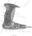
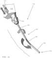
- FIG. 1shows a left side view of an applicator instrument for dispensing surgical fasteners, in accordance with one embodiment of the present invention.
- FIG. 2shows a perspective view of a right side of the applicator instrument of FIG. 1 during a surgical procedure, in accordance with one embodiment of the present invention.
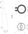
- FIG. 3shows a perspective view of a surgical fastener dispensed from the applicator instrument shown in FIGS. 1 and 2 , in accordance with one embodiment of the present invention.
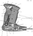
- FIG. 4 Ashows a right side elevation view of a proximal end of an applicator instrument used for dispensing surgical fasteners with a right half of a handle removed for showing internal components, in accordance with one embodiment of the present invention.
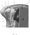
- FIG. 4 Bshows the proximal end of the applicator instrument of FIG. 4 A with a trigger and a two-step drive gear being transparent, in accordance with one embodiment of the present invention.
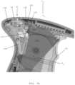
- FIG. 4 Cshows a perspective view of the proximal end of the applicator instrument shown in FIG. 4 A .
- FIGS. 5 A- 5 Cshow a counter for counting how many surgical fasteners have been dispensed from an applicator instrument for dispensing surgical fasteners, in accordance with one embodiment of the present invention.
- FIG. 6 Ashows an applicator instrument during a first stage of a firing cycle, in accordance with one embodiment of the present invention.
- FIG. 6 Bshows an applicator during a second stage of a firing cycle, in accordance with one embodiment of the present invention.
- FIG. 6 Cshows an applicator during a third stage of a firing cycle, in accordance with one embodiment of the present invention.
- FIG. 6 Dshows an applicator during a fourth stage of a firing cycle, in accordance with one embodiment of the present invention.
- FIG. 6 Eshows an applicator during a fifth stage of a firing cycle, in accordance with one embodiment of the present invention.
- FIG. 6 A- 1shows the counter of FIGS. 5 A- 5 C during the first stage of the firing cycle shown in FIG. 6 A .
- FIG. 6 B- 1shows the counter during the second stage of the firing cycle shown in FIG. 6 B during which a rotating link has begun to contact a counter.
- FIG. 6 C- 1shows the counter during the third stage of the firing cycle shown in FIG. 6 C during which the counter has begun to deflect a dwell beam of the counter.
- FIG. 6 D- 1shows the counter during the fourth stage of the firing cycle shown in FIG. 6 D during which the counter has pivoted to a rear position.
- FIG. 6 E- 1shows the counter during the fifth stage of the firing cycle shown in FIG. 6 E during which the dwell beam of the counter is deflected further by a rotating link.
- FIGS. 7 A- 7 Cshow the movement of the counter of FIGS. 5 A- 5 C during delivery of the last surgical fastener, in accordance with one embodiment of the present invention.
- FIG. 8shows a side elevation view of an advancer element that cycles back and forth for advancing surgical fasteners toward a distal end of an applicator instrument and an anti-backup member for preventing the surgical fasteners from moving proximally, in accordance with one embodiment of the present invention.
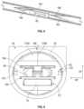
- FIG. 9shows a cross-sectional view of an elongated shaft of an applicator instrument including the advancer element and the anti-backup member shown in FIG. 8 , in accordance with one embodiment of the present invention.
- FIG. 10 Ashows a cross-sectional view of a distal end of a right guide member disposed inside a shaft of an applicator instrument including the advancer element and the anti-backup member shown in FIG. 8 , in accordance with one embodiment of the present invention.
- FIG. 10 Bshows the right guide member of FIG. 10 A with a wire staging spring secured to the guide member, in accordance with one embodiment of the present invention.
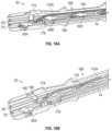
- FIG. 11 Ashows a distal end of an applicator instrument including a left guide member, a wire staging spring and a cap having a surgical fastener dispensing window, in accordance with one embodiment of the present invention.
- FIG. 11 Bshows a bottom view of FIG. 11 A .
- FIGS. 12 A- 12 Eshow a method of aligning a lead surgical fastener with an insertion fork at a distal end of a firing rod, in accordance with one embodiment of the present invention.
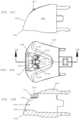
- FIG. 13 Ashows a perspective view of a cap secured to a distal end of an elongated shaft of an applicator instrument, in accordance with one embodiment of the present invention.
- FIG. 13 Bshows a bottom plan view of FIG. 13 A .
- FIG. 13 Cshows a cross-sectional view of the cap shown in FIG. 13 A .
- FIG. 14 Ashows a top view of an open skirt mesh having a distal end of an applicator instrument inserted into a central opening of the open skirt mesh, in accordance with one embodiment of the present invention.
- FIG. 14 Bshows a magnified cross-sectional view of FIG. 14 A .
- FIG. 14 Cshows a view of a stage of an open hernia repair procedure with an open skirt mesh inserted into a surgical opening and an applicator instrument used for mesh fixation, in accordance with one embodiment of the present invention.
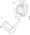
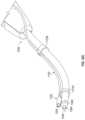
- FIG. 15 Ashows a left side view of an applicator instrument having an elongated shaft and a cap secured to a distal end of the elongated shaft, in accordance with one embodiment of the present invention.
- FIG. 15 Bshows a perspective view of the cap shown in FIG. 15 A .
- FIG. 15 Cshows a top perspective view of the cap shown in FIG. 15 B .
- FIG. 16shows the cap at the distal end of the applicator instrument of FIGS. 15 A- 15 C inserted between top and bottom mesh pieces of an open skirt mesh, in accordance with one embodiment of the present invention.
- FIG. 17shows an applicator instrument having an elongated shaft that is rotatable, in accordance with one embodiment of the present invention.
- FIGS. 18 A- 18 Cshow an edge adapter cap with a living hinge that is securable to a distal end of an elongated shaft of an applicator instrument, in accordance with one embodiment of the present invention.
- FIG. 19shows a side view of a distal end of an applicator instrument for dispensing surgical fasteners including a curved outer shaft and a shaft rotating element for changing the orientation of a distal end of the curved outer shaft relative to a proximal end of the curved outer shaft, in accordance with one embodiment of the present invention.
- FIG. 20shows a cross-sectional view of the distal end of the applicator instrument including the curved outer shaft shown in FIG. 19 .
- FIG. 21shows a perspective view of a distal end of an applicator instrument for dispensing surgical fasteners including an articulating element and an outer shaft rotating element for changing the orientation of the distal end of the outer shaft relative to a proximal end of the outer shaft, in accordance with one embodiment of the present invention.
- FIG. 22shows a cross-sectional view of the outer shaft shown in FIG. 21 .
- FIG. 23shows an applicator instrument for dispensing surgical fasteners, the applicator instrument having an object imaging system, in accordance with one embodiment of the present invention.
- FIG. 24shows an elongated shaft for the applicator instrument of FIG. 23 with an imaging device located at a distal end of the elongated shaft, in accordance with one embodiment of the present invention.
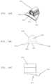
- FIG. 25 Ashows a front perspective view of a cap secured to a distal end of an elongated shaft of an applicator instrument, the cap including an imaging device and light sources, in accordance with one embodiment of the present invention.
- FIG. 25 Bshows a front view of the cap shown in FIG. 25 A .
- FIG. 25 Cshows a left side view of the cap shown in FIG. 25 A .
- FIG. 25 Dshows a top plan view of the cap shown in FIG. 25 A .
- FIG. 25 Eshows a cross-sectional view of the cap shown in FIG. 25 D taken along line 25 E- 25 E of FIG. 25 D .
- FIG. 26shows a schematic diagram of an imaging system for the applicator instrument, in accordance with one embodiment of the present invention.
- FIG. 27shows a side elevation view of an applicator instrument for dispensing surgical fasteners and an endoscopic instrument having an imaging device that is attachable to the applicator instrument, in accordance with one embodiment of the present invention.
- FIG. 28 Ashows a distal end of the endoscopic instrument shown in FIG. 27 , in accordance with one embodiment of the present invention.
- FIG. 28 Bshows a schematic view of a distal end of the endoscopic instrument shown in FIG. 28 A .
- FIG. 29shows a clip for attaching an endoscopic instrument having an imaging device to an applicator instrument, in accordance with one embodiment of the present invention.
- FIG. 30 Ashows a side elevation view of an applicator instrument having an endoscopic instrument with an imaging device attached to the applicator instrument, in accordance with one embodiment of the present invention.
- FIG. 30 Bshows a rear perspective view of the applicator instrument and the endoscopic instrument shown in FIG. 30 A .
- FIG. 30 Cshows a front perspective view of the applicator instrument and the endoscopic instrument shown in FIGS. 30 A and 30 B .
- an applicator instrument 30 for dispensing surgical fastenershas a proximal end 32 , a distal end 34 , and a longitudinal axis A 1 -A 1 that extends between the proximal and distal ends.
- the applicator instrument 30desirably includes a housing 35 , a handle 36 extending upwardly from the housing, a trigger 38 mounted on the handle, and an elongated shaft 40 that extends distally from the housing 35 .
- the elongated shaft 40includes a first section 42 that extends along the longitudinal axis A 1 -A 1 of the applicator instrument, and a second section 44 that is angled or curved relative to the first section 42 .
- a cap 46is secured to the distal end of the elongated shaft 40 .
- the cap 46preferably has a distal face 48 that slopes away from a lower distal edge of the cap and toward the proximal end 32 of the applicator instrument 30 .
- the handle 36includes an upper end 50 containing a counter 52 that indicates how many surgical fasteners have been dispensed and/or how many surgical fasteners remain loaded in the applicator instrument.
- the counter 52locks the applicator instrument from further use when the last surgical fastener has been dispensed.
- the counter 52is visible at the upper end 50 of the handle 36 to provide a visual indicator of how many of the surgical fasteners have been dispensed.
- the upper end of the handledefines the top of the applicator instrument 30 .
- the housing 35has a lower end 54 that defines the bottom of the applicator instrument 30 .
- the handle 36preferably leans toward the distal end 34 of the applicator instrument 30 to provide improved ergonomics for a surgeon so that the surgeon may maintain his/her elbow and wrist in a neutral position.
- the handle 36preferably extends along a longitudinal axis A 2 -A 2 that defines an acute angle ⁇ 1 with the longitudinal axis A 1 -A 1 of the applicator instrument.
- the angle ⁇ 1is about 70-80° and more preferably about 75°.
- the lower end 54 of the housing 35preferably faces toward a patient and the upper end 50 of the handle 36 preferably faces away from the patient.
- the applicator instrument 30 shown in FIG. 1may be used for dispensing surgical fasteners during a surgical procedure such as an open hernia repair procedure.
- the applicator instrument 30has a plurality of surgical fasteners that are pre-loaded in the shaft 40 for being dispensed when the trigger 38 is squeezed.
- a single surgical fasteneris dispensed each time the trigger 38 is squeezed.
- the applicator instrument 30is used for dispensing surgical fasteners for the fixation of a mesh, such as a surgical mesh, to the soft tissue of a patient.
- the angled second section 44 of the shaft 40has been inserted into a surgical opening.
- the lower end 54 of the housing 35faces toward the patient and the upper end 50 of the handle 36 faces away from the patient.
- a surgeonmay grasp the handle 36 and squeeze the trigger 38 for dispensing a surgical fastener from the distal end of the shaft 40 .
- the surgeonpulls the trigger 38 proximally (i.e. toward the proximal end 32 of the applicator instrument) for dispensing the surgical fasteners.
- the surgeonpreferably applies counter pressure on the patient's tissue that opposes the distal end of the applicator instrument.
- a single surgical fasteneris dispensed each time the surgeon pulls the trigger 38 proximally, and the system finishes the firing cycle when the trigger is released for allowing the trigger to return distally.
- the second section 44 of the shaft 40 that is curved and/or angled relative to the first section 42 of the shaftpreferably facilitates the accurate placement of surgical fasteners into soft tissue.
- the applicator instrument 30is used during an open surgical repair procedure for addressing ventral hernias.
- the distal-most end of the curved shaft 40is inserted into a pocket of an open skirt mesh having a top mesh piece and a bottom mesh piece that are joined together at a peripheral seam, whereupon surgical fasteners are dispensed from the distal end of the applicator instrument for fixing the top mesh piece to soft tissue.
- the handle 36 and the trigger 38are positioned above the housing 35 of the applicator instrument. This configuration places the trigger 38 in a position that provides multiple advantages to a surgeon.
- the handle 36is located in a position that allows a surgeon's elbow to be in a neutral position.
- the handle 36is also angled forward toward the distal end 34 of the applicator instrument 30 to facilitate a neutral position for the surgeon's wrist.
- the position of the handle 36 above the housing 35 of the applicator instrument 30allows the bottom end 52 of the housing 35 to clear the body of the patient, which is particularly preferable for open abdominal procedures.
- the combination of an upward curvature of the shaft 40 and the forward angulation or lean of the handle 36 toward the distal end 34 of the applicator instrumentcomplement each other to facilitate the delivery of surgical fasteners along an upward trajectory in the intended direction of fixation.
- the applicator instrument 30is a multi-fire device including a plurality of surgical fasteners stored therein as disclosed in commonly assigned U.S. Patent Application Publication Nos. US 2010/0292715; US 2010/0292712; US 2010/0292710; US 2010/0292713; and US 2011/079627, the disclosures of which are hereby incorporated by reference herein.
- the applicator instrumentincludes a plurality of surgical fasteners stored in series along the length of the shaft 40 .
- the shaft 40preferably includes a pair of flat stampings having tabbed features incorporated therein. One of the flat stampings is stationary for preventing the surgical fasteners from moving proximally within the shaft 40 .
- the other flat stampingcycles in distal and proximal directions each time the trigger 38 is squeezed and then released to facilitate incremental advancement of the surgical fasteners along the length of the shaft 40 .
- the flat nature of the stampingsprovides the stampings with flexibility so that the stampings may curve to conform to the curvature of the shaft while guiding the surgical fasteners along the curved path defined by the shaft 40 .
- the applicator instrumentincludes a molded guide component that defines the curved path of travel for the surgical fasteners.
- the flat stampingsare placed inside the molded guide component.
- the molded guide componentpreferably provides minimal friction and distortion upon the surgical fasteners, the advancer element and the anti-backup member as the surgical fasteners move distally through the shaft 40 .
- the guide componentis made of molded plastic and includes two halves that are assembled together for being contained within a conduit extending through the elongated shaft 40 .
- a plurality of surgical fastenersare pre-loaded into the shaft of the applicator instrument 30 shown in FIGS. 1 and 2 .
- a single surgical fastener 60includes a proximal end 62 and a distal end 64 having a pair of tapered ends 66 , 68 that are spaced from one another for capturing mesh fibers between the tapered ends.
- the surgical fastener 60has one or more of the features disclosed in commonly assigned U.S. Patent Application Publication Nos. US 2010/0292715, US 2010/0292712, US 2010/0292710, US 2010/0292713, and US 2011/079627, the disclosures of which are hereby incorporated by reference herein.
- the applicator instrument 30includes the housing 35 that contains a firing system, and a handle 36 projecting upwardly from the housing, whereby the handle has an upper end 50 that contains the counter 52 .
- the handleincludes the trigger 38 that is adapted to be pulled along a linear path toward the proximal end 32 of the applicator instrument 30 .
- the trigger 38is adapted to move along a linear path A 3 -A 3 that defines an angle ⁇ 2 of about 10-20° and more preferably about 15° with the longitudinal axis A 1 -A 1 of the applicator instrument 30 .
- the applicator instrument 30includes a firing system 70 having a spring block 72 , a firing rod 74 , and a firing spring that stores energy as the trigger 38 is squeezed.
- the firing system 70preferably includes one or more features similar to those disclosed in commonly assigned U.S. Patent Application Publication Nos. US 2010/0292715, US 2010/0292712, US 2010/0292710, US 2010/0292713, and US 2011/079627, the disclosures of which are hereby incorporated by reference herein.
- the firing system 70is desirably coupled with the trigger via a trigger rack 76 that slides proximally and distally with the trigger along the axis A 3 -A 3 .
- the trigger rackis coupled with a drive gear 78 that rotates in a counter-clockwise direction when the trigger 38 is squeezed toward the proximal end of the applicator instrument, and rotates in a clockwise direction when the trigger 38 is released and moves distally toward the distal end of the applicator instrument.
- the drive gear 78has external gear teeth 80 that mesh with teeth provided at an upper end of a sliding yoke 82 .
- the yoke 82slides in a distal direction along the axis A 1 -A 1 .
- the drive gear 78rotates in a clockwise direction
- the yoke 82slides in a proximal direction along the axis A 1 -A 1 , preferably with a gear ratio of 0.9 to 1.5.
- the applicator instrument 30includes a ratchet pawl 84 having a ratchet spring, which is similar to the subassembly disclosed in commonly assigned U.S. Patent Application Publication Nos. US 2010/0292715, US 2010/0292712, US 2010/0292710, US 2010/0292713, and US 2011/079627, the disclosures of which are hereby incorporated by reference herein.
- the ratchet pawl 84ensures that the sliding yoke 82 moves to its distal-most position before it is able to change direction and move proximally back into the original position shown in FIG. 4 A .
- the applicator instrument 30includes a trigger return spring 86 that normally urges the trigger 38 to move distally.
- the trigger return spring 86includes a first arm 88 that is secured within a molded portion of the handle 36 , and a second arm 90 that preferably engages the trigger 38 .
- a proximal end of the trigger 38has a tab 92 and the second arm 90 engages the tab for normally urging the trigger distally.
- the trigger return spring 86preferably stores energy therein as the trigger 38 is squeezed and transfers the stored energy back to the trigger when the trigger is released for moving the trigger distally.
- the trigger return spring 86acts directly on the rotating links 110 and 112 .
- the counter 52includes a rotatable disc 94 having gear teeth 96 .
- the counter 52includes a window 98 that is formed in the upper end 50 the handle 36 to provide visual access to a top surface of the rotatable disc 94 .
- the counterdesirably includes a lock-out pin 100 and a lock-out pin spring (not shown) in contact with the lock-out pin.
- the applicator instrumentdesirably includes a lock-out pin cover 102 that partially covers a portion of the lock-out pin 100 .
- the counter 52has a lock-out counter 104 that is pivotally secured to the handle 36 via a lock-out counter pivot 106 .
- the counter 52also includes a lock-out counter spring 108 that normally urges the lock-out counter 104 to pivot toward the distal end of the applicator instrument 30 .
- the lock-out counter 104is adapted to toggle back and forth about the pivot 106 during each firing cycle.
- FIG. 4 Bshows the applicator instrument 30 of FIG. 4 A with the trigger being transparent for clearly showing a first rotating link 110 and a second rotating link 112 coupled with the trigger 38 .
- the first rotating link 110is disposed inside the trigger 38 and is pivotally secured to the trigger 38 via a first pivot 114 .
- the first rotating link 110has an upper end 116 having upper gear teeth 118 that mesh with a rack 120 located inside the upper end of the handle 36 .
- the first rotating link 110has a lower end 122 having lower gear teeth 124 .
- the trigger 38includes a first internal slot 125 formed therein that is adapted to receive the first pivot 114 during assembly. Pivot 114 passes through a “snap fit” feature of the first internal slot 125 during assembly. This ensures that the two rotating links 110 , 112 are pivotally secured.
- the second rotating link 112is pivotally secured to the trigger 38 via a second pivot 126 .
- the second rotating link 112has an upper end 128 with upper gear teeth 130 that mesh with the lower gear teeth 124 of the first rotating link 110 .
- the first and second rotating links 110 , 112are coupled with one another via the opposing gear teeth 124 , 130 , which ensure that the first and second rotating links 110 , 112 rotate at the same rate.
- the second rotating link 112has a lower end 132 having bottom teeth 134 that mesh with opposing teeth molded into a second rack disposed above the housing 35 (not shown).
- the trigger 38includes a second molded slot 136 that receives the second pivot 126 during assembly.
- Pivot 114passes through a “snap fit” feature of internal slot 136 during assembly. This ensures that the two rotating links 110 , 112 are pivotally secured. Further, the rotating gear links 110 , 112 have paired offset teeth 124 , 130 to allow synchronized timing between two gears made from the same mold.
- the configuration of the first and second rotating links 110 , 112 within the handle 36 , and the pivotal connection of the first and second rotating links with the trigger 38enables the trigger 38 to move along a single linear path, namely axis A 3 -A 3 .
- the linear motion of the trigger 38allows the force and distance required to squeeze the trigger to remain consistent no matter where the squeezing forces are concentrated along the length of the trigger, which minimizes the likelihood of binding of the trigger.
- the trigger return spring 86normally urges the trigger 38 to move distally.
- the trigger return spring 86has the first arm 88 secured within a molded portion of the handle 36 and the second arm 90 that engages a tab 92 at a proximal face of the trigger 38 .
- the tab 92urges the second arm 90 of the trigger return spring 86 to move proximally for storing energy in the spring 86 .
- the trigger 38may be released, whereupon the second arm 90 of the spring 86 urges the trigger 38 to move distally for returning the trigger to the original position shown in FIG. 4 C .
- the housing 35 and the handle 36includes left and right halves that are assembled together.
- the handle halvesare assembled together with press fit pins.
- the trigger 38is captured between the left and right halves of the housing and the handle.
- the trigger 38travels in distal and proximal directions along a linear path having a total length of about 0.9 inches.
- the applicator instrumentpreferably has physical stops at the proximal and distal ends of the linear path of travel of the trigger rack 76 that halt the proximal and distal movement of the trigger along the linear path A 3 -A 3 .
- the left and right halvesare desirably made from a polymer such as glass reinforced polycarbonate.
- the triggeris made of a polymer material such as a glass reinforced polycarbonate.
- the housing 35contains a firing system having the firing spring, a spring block and a firing rod, as disclosed in commonly assigned U.S. Patent Applicant Publication Nos. US 2010/0292715, US 2010/0292712, US 2010/0292710, US 2010/0292713, and US 2011/079627, the disclosures of which are hereby incorporated by reference herein.
- the spring block 72 and the firing rod 74are adapted to move in distal and proximal directions along the longitudinal axis A 1 -A 1 .
- the trigger 38is connected with the trigger rack 76 by means of a tab extending from the trigger 38 that protrudes between two bosses on the trigger rack 76 .
- the tolerance of the fit between the trigger tab and the trigger rack bossesis precise and close to allow minimal free play between the trigger and the trigger rack.
- the existence of two separate trigger partsallows for a stronger material (e.g., metal such as stainless steel) to be used for the trigger rack 76 .
- the separation of the trigger tab from the trigger rackensures that any rotational forces exerted by the user on the trigger 38 are limited to the trigger and are not exerted upon the trigger rack 76 .
- the trigger rack 76is captured between the left and right handle halves and is in contact with the drive gear 78 .
- the trigger rack 76is adapted to slide along an axis that is parallel with the axis of movement A 3 -A 3 of the trigger 38 .
- the trigger rack travelis limited to about 0.9 inches, with both distal and proximal stopping features being located within the left handle half.
- the trigger rackhas trigger rack gear teeth provided at an underside thereof.
- the drive gear 78has two sets of gear teeth of differing radii to provide a two-step gear, and the trigger rack gear teeth engage the smaller of the gears of the drive gear 78 .
- the rotating links 110 , 112pivot about the respective first and second pivots 114 , 126 protruding into opposing through holes in the trigger 38 .
- the rotating links 110 , 112are preferably captured by and restricted in their rotational motion by features of the trigger.
- the rotating linksare coupled to each other via paired opposing gear teeth 124 , 130 positioned near the middle of the hand-squeezing area of the trigger 38 .
- these matching gear teeth 124 , 130have a face width of approximately 0.1 inch, and a pitch diameter of about 0.875 inches.
- the first and second rotating links 110 , 112also have outer gear teeth 118 , 134 , respectively, with a face of about 0.1 inch and a pitch diameter that is about 1.042 inches. These outer gear teeth 118 , 134 desirably mate with corresponding opposing rack gear features formed in the handle halves, one in the right handle half, and one in the left handle half.
- first and second rotating links 110 , 112enables the trigger 38 to move in a linear fashion along the axis A 3 -A 3 , and also prevents the trigger from rotating about a center point when squeezing forces are applied unevenly along the hand-squeezing area of the trigger.
- the ability of the trigger mechanism to convert linear motion of the trigger into rotary motion through the drive gear 78minimizes friction and any risk of binding.
- the first and second rotating links 110 , 112are preferably made from a polymer such as a glass reinforced polycarbonate.
- the drive gear 78desirably connects the trigger rack 76 to the yoke 82 of the firing system 70 .
- the yoke 82 and the firing system 70are preferably similar to that disclosed in the firing system of commonly assigned U.S. Patent Application Publication Nos. US 2010/0292715, US 2010/0292712, US 2010/0292710, US 2010/0292713, and US 2011/079627, the disclosures of which are hereby incorporated by reference herein.
- the drive gearpreferably transfers the motion of the trigger along axis A 3 -A 3 to the motion of the yoke along the axis A 1 -A 1 .
- these two axesdiffer by about 15° such that proximal movement of the trigger 38 along axis A 3 -A 3 results in distal movement of the yoke 82 along axis A 1 -A 1 .
- the drive gear 78has a gear ratio that results in 0.9 inches of trigger travel producing 1.5 inches of yoke travel.
- the two-step drive gear 78is preferably made of a metal such stainless steel. The gear may be mounted on a metal pin for rotating about the metal pin. In one embodiment, the pin about which the drive gear 78 rotates is located and constrained between the left and right handle halves.
- the trigger return spring 86is positioned inside the handle so that the coils of the spring 86 are captured over a post that extends between the left and right handle halves.
- a first arm of the trigger return springis fixed relative to the handle halves and is captured within a pocket, preferably formed within the left handle half.
- a second or moving arm of the trigger return springdesirably has an L bend at its distal end, and is biased against the trigger such that the trigger is urged toward a forward distal position.
- the trigger return spring 86desirably exerts a force upon the trigger that is about two pounds pre-loaded and nine pounds under final load. In one preferred embodiment, the trigger return spring 86 provides a force of about five pounds pre-loaded and seven pounds final load.
- the trigger return spring 86is desirably made of metal such as stainless steel.
- the applicator instrument 30includes the counter 52 having the rotatable disc 94 and the gear teeth 96 projecting below the rotatable disc 94 .
- a window 98is formed in the upper end 50 of the handle 36 to provide visual access to the top surface of the rotatable disc 94 .
- the counter 52includes a lock-out pin 100 that is adapted to drop along the axis V 1 -V 1 ( FIG. 5 A ) when a slot formed in the rotatable disc 94 has been rotated into alignment with an extension arm 101 of the lock-out pin 100 .
- the counter 52also includes a lock-out pin cover 102 that extends over a portion of the lock-out pin 100 .
- the counter 52has a lock-out counter 104 that is pivotally secured to the left handle half via a pivot point 106 .
- a lock-out counter spring 108normally urges the upper end of the lock-out counter 104 to pivot toward the distal end of the applicator instrument 30 .
- the lock-out counter 104toggles back and forth during a firing cycle for rotating the rotatable disc 94 one position to indicate that one surgical fastener has been fired.
- the rotatable disc 94is adapted to be rotated one additional position each time another surgical fastener is dispensed.
- the lock-out counter 104has a flexible cantilever beam 115 that is engaged by the first rotating link 110 for toggling the lock-out counter 104 from the forward position to the rear position.
- the lock-out counter 104has a proximal tooth 120 and a distal tooth 122 that are adapted to engage the gear teeth 96 projecting below the rotatable disc 94 .
- the proximal tooth 122engages the gear teeth 96 for rotating the disc 94 one half of a position in the direction indicated R 1 .
- the trigger 38contacts the lock-out counter 104 for pivoting the upper end of the lock-out counter in a proximal direction so that the distal tooth 122 engages the gear 96 .
- the lock-out counter spring 108pivots the upper end of the lock-out counter 104 in a distal direction so that the proximal tooth 120 engages the gear teeth 96 for rotating the disc 94 one half of a position in the direction R 1 .
- the rotatable disc 94is rotated one position (indicating that one surgical fastener has been fired) each time the upper end of the lock-out counter 104 pivots proximally and then distally to the initial position shown in FIG. 5 B .
- the lock-out pin 100drops for locking the trigger 38 in a proximal position.
- FIG. 5 Cshows the window 98 formed at the upper end 50 of the handle 36 .
- the window 98provides visual access to the top surface of the rotatable disc 94 to provide an indication of how many surgical fasteners have been fired and/or how many surgical fasteners remain in the applicator instrument 30 .
- the counter and lock-out assembly disclosed hereinis generally similar to the structure disclosed in commonly assigned U.S. Patent Application Publication Nos. US 2010/0292715, US 2010/0292712, US 2010/0292710, US 2010/0292713, and US 2011/079627, the disclosures of which are hereby incorporated by reference herein.
- the lock-out pin spring and the lock-out counter springare desirably made of a metal such as stainless steel.
- the components of the counter 52are preferably made of polymer materials such as acetal, ABS, glass reinforced acetal, or combinations thereof.
- FIGS. 6 A and 6 A- 1show the applicator instrument 30 including the position of the trigger 38 and the counter 52 at the beginning of a firing cycle, which is also referred to herein as the first stage of the firing cycle.
- the second arm 90 of the trigger return spring 86rests against the tab 92 of the trigger 38 to provide a pre-load force that biases the trigger distally.
- the trigger 38is constrained to move along the linear path of axis A 3 -A 3 by the pivots 114 , 126 and the trigger rack 76 .
- the trigger rack 76is constrained from distal movement by the distal stop 77 formed in the left handle half.
- the lock-out counter 104 of the counter 52is pivoted distally by the lock-out counter spring 108 .
- the lock-out pin 100is held up by the rotatable disc 94 .
- FIGS. 6 B and 6 B- 1show the applicator instrument 30 during a second stage of a firing cycle.
- the trigger 38has been partially squeezed so that the trigger 38 and the trigger rack 76 have moved proximally about 0.486 inches from the start position shown in FIGS. 6 A and 6 A- 1 .
- the first rotating link 110has made initial contact with the dwell beam 115 of the lock-out counter 104 .
- the second arm 90 of the trigger return spring 86has flexed proximally for increasing the spring force against the trigger 38 .
- FIGS. 6 C and 6 C- 1show the applicator instrument 30 during a third stage of the firing cycle.
- the trigger 38 and the trigger rack 76have moved proximally about 0.537 inches from the beginning the firing cycle (see FIG. 6 A ) due to continued squeezing of the trigger 38 .
- Further proximal movement of the trigger rack 76 along the axis A 3 -A 3results in further rotation of the drive gear 78 , which causes corresponding distal movement of the yoke 82 along the axis A 1 -A 1 .
- energymay be stored in a firing spring located inside the spring block 72 .
- the second arm 90 of the trigger return spring 86has been further flexed proximally for increasing the return force against the trigger 38 .
- the first rotating link 110deflects the dwell beam 115 of the lock-out counter 104 proximally by about 0.029 inches.
- the force applied to the dwell beam 115 by the first rotating link 110is in equilibrium with the counter force provided by the lock-out counter spring 108 , so that the lock-out counter 104 is “primed” for toggling from the forward position shown in FIG. 6 C- 1 to a rear position.
- FIGS. 6 D and 6 D- 1show the applicator instrument 30 during a fourth stage of the firing cycle.
- the trigger 38 and the trigger rack 76have moved proximally about 0.716 inches due to continued squeezing of the trigger 38 .
- the second arm 90 of the trigger return spring 86has further flexed proximally for increasing the return force against the trigger 38 .
- Linear movement of the trigger rack 76 in a proximal direction along the axis A 3 -A 3results in continued counter-clockwise rotation of the drive gear 78 , which causes corresponding distal sliding motion of the yoke 82 along the axis A 1 -A 1 toward the distal end of the applicator instrument 30 , and storing additional energy in the firing spring 75 inside the spring block 72 .
- the first rotating link 110has deflected the dwell beam 115 of the lock-out counter 104 by about 0.044 inches.
- FIGS. 6 E and 6 E- 1show the applicator instrument 30 during a fifth stage of the firing cycle.
- the trigger 38 and the trigger rack 76have moved proximally about 0.900 inches from the commencement of the firing cycle ( FIG. 6 A ) due to continued squeezing of the trigger.
- the proximal sliding movement of the trigger rack 76is halted by a proximal stop 85 molded into the handle 36 .
- the trigger rack 76has contacted the proximal stop 85 and the proximal movement of the trigger 38 and the trigger rack 76 is complete.
- the second arm 90 of the trigger return spring 86has flexed further for increasing the return force against the trigger 38 to a peak value.
- Proximal movement of the trigger rack 76 along axis A 3 -A 3has resulted in continued rotation of the drive gear 78 , which, in turn, causes distal movement of the yoke 82 along axis A 1 -A 1 as described in commonly assigned U.S. Patent Application Publication Nos. US 2010/0292715, US 2010/0292712, US 2010/0292710, US 2010/0292713, and US 2011/079627, the disclosures of which are hereby incorporated by reference herein.
- the firing rodis released and the energy in the firing spring is transferred to the firing rod to move the firing rod distally for dispensing a surgical fastener.
- the first rotating link 110has deflected the dwell beam 115 of the lock-out counter 104 by about 0.115 inches.
- the upper end of the lock-out counter 104remains toggled over to the rear position whereby the distal tooth 122 contacts the gear 96 .
- the trigger 38has been fully squeezed and the drive gear 78 has advanced the proximal end of the yoke 82 distally beyond the ratchet pawl 84 .
- the ratchet pawlmay re-set so that the yoke 82 is free to once more slide toward the proximal end 32 of the applicator instrument 30 for commencing another firing cycle.
- the energy stored in the trigger return spring 86is transferred to the trigger 38 for urging the trigger to move in a distal direction along the axis A 3 -A 3 for returning the trigger to the initial trigger position shown in FIG. 6 A .
- Corresponding resetting actions of the yoke 82 and the firing system 70are similar to the movements disclosed in commonly assigned U.S. Patent Application Publication Nos. US 2010/0292715, US 2010/0292712, US 2010/0292710, US 2010/0292713, and US 2011/079627, the disclosures of which are hereby incorporated by reference herein.
- the first rotating link 110moves distally for removing a compression force on the dwell beam 115 of the lock-out counter 104 .
- the lock-out return spring 108preferably toggles the upper end of the lock-out counter 104 in a distal direction and back to the forward position shown in FIG. 6 A- 1 . The back and forth toggling of the lock-out counter 104 will result in incremental rotation of the rotatable disc 94 of the counter 52 .
- the counter 52locks the trigger in a proximal position ( FIG. 6 E ) when the last surgical fastener has been fired.
- the trigger 38has a hook 140 projecting from a proximal end thereof. The hook 140 moves simultaneously with the trigger 38 as the trigger moves in proximal and distal directions along the axis A 3 -A 3 . In FIG. 7 A , the trigger hook 140 is proximal to the lock-out pin hook 142 .
- the lock-out pin 100has a lock-out pin hook 142 that is adapted to engage the trigger hook 140 when the last surgical fastener has been fired.
- a radial slot provided in the rotatable disc 94is aligned with the arm 101 of the lock-out pin 100 .
- the lock-out pin 100is free to fall toward the bottom of the applicator instrument along the axis V 1 -V 1 .
- the lock-out pin 100is urged downward by a lock-out pin spring 150 .
- the dwell beam 115 of the lock-out counter 104ensures that the lock-out pin 100 drops before the trigger hook 140 passes beyond the lock-out pin hook 142 .
- a ramp feature on the leading edge of the trigger hook 140deflects the lock-out pin 100 upward along the axis V 1 -V 1 .
- the lock-out pin 100eventually drops again so that the hook 142 of the lock-out pin 100 is distal to the hook 140 connected with the trigger 38 .
- the trigger return spring 86urges the trigger distally until the lock-out pin hook 142 engages the trigger hook 140 to halt the trigger 38 from moving further distally along the axis A 3 -A 3 .
- the trigger 38is locked in the position shown in FIG. 7 C and the applicator instrument 30 may no longer be used for dispensing surgical fasteners.
- the firing systempreferably includes an advancer element 160 having advancer element tabs 162 and an anti-backup member 164 having anti-backup tabs 166 .
- the advancer element 160cycles distally and proximally for advancing surgical fasteners 60 one segment toward the distal end of the applicator instrument.
- the trigger 38FIG. 1
- the advancer element 160moves distally (to the left in FIG. 8 ) whereupon the advancer element tab 162 abuts against a rear of the surgical fastener 60 for advancing the surgical fastener in a distal direction.
- the advancer element 160moves in a proximal direction toward the proximal end of the applicator instrument.
- the anti-backup tabs 166prevent the surgical fasteners from moving proximally as the advancer element moves proximally.
- the advancer element 160moves distally each time the trigger is squeezed and moves proximally when the trigger is released for returning to a start position at the beginning of a firing cycle.
- the anti-backup member 164remains stationary during the firing cycles.
- the anti-backup tabs 166preferably contact the surgical fasteners for preventing the surgical fasteners from moving proximally within the elongated shaft 40 ( FIG. 1 ) of the applicator instrument.
- the applicator instrument 30includes the elongated shaft 30 , which is preferably angled or curved, and a guide member 168 that extends through the shaft.
- the guide member 168may be a molded part including an advancer element channel AC and a firing channel FC.
- the guide member 168preferably has a first half 170 A and a second half 170 B that are assembled together.
- the anti-backup member 164 , the advancer element 160 , and the surgical fasteners 60are positioned within the advancer element channel AC of the first half 170 A of the guide member, and the firing rod 74 and an insertion fork are positioned within the firing channel FC of the first half 170 A of the guide member.
- the second half 170 B of the guide memberis assembled with the first half 170 A for forming the assembled guide channel 168 .
- the surgical fasteners 60advance through the advancer element channel AC while lying within a laterally extending horizontal plane HP that is perpendicular to a vertical plane VP extending through the top and bottom of the applicator instrument.
- the orientation of the surgical fasteners within the guide member 168enables the surgeon to control and/or be aware of the orientation of the surgical fasteners as they are dispensed from the shaft of the applicator instrument.
- the advancer element 160advances the surgical fastener 60 distally through the advancer element channel AC and toward the distal end of the shaft 40 .
- a staging leaf attached to the distal end of the anti-backup member 164transfers the lead surgical fastener 60 from the advancer element channel AC to the firing channel FC for being aligned with the insertion fork at the distal end of the firing rod 74 .
- FIG. 10 Ashows the distal end of the first half 170 A of the guide member 168 .
- the second half 170 B ( FIG. 9 ) of the guide memberhas been removed to more clearly show the advancer element channel AC and the firing channel FC of the guide member 168 .
- twenty surgical fasteners 60 A, 60 B, 60 C, . . . 60 Tare positioned between the advancer element 160 and the anti-backup member 164 .
- the advancer element 160cycles back and forth for advancing the surgical fasteners 60 A, 60 B, 60 C, . . . 60 T toward the distal end of the advancer element channel AC.
- the distal end of the anti-backup member 164includes a staging leaf 174 that moves the lead surgical fastener 60 A into the firing channel FC for alignment with the insertion fork 176 at the distal end of the firing rod 74 .
- the applicator instrument 30includes a staging spring 178 , such as a wire staging spring that is adapted to urge the staging leaf 174 to move into alignment with the insertion fork 176 .
- the wire staging spring 174is U-shape and has a closed distal end 180 that passes through a window 182 formed in the distal end of the guide member 168 .
- the closed distal end 180 of the wire staging spring 178preferably engages the staging leaf 174 for urging the staging leaf to move into alignment with the insertion fork 176 .
- the wire staging spring 178transfers the lead surgical fastener 60 A from the advancer element channel AC to the firing channel FC for being aligned with the insertion fork 176 at the distal end of the firing rod 74 .
- the firing rod and the insertion forkmay then be extended for guiding the tines of the insertion fork onto the lead surgical fastener 60 A.
- the wire staging spring 178has a proximal end 184 that is secured to the guide member 168 and a closed distal end 180 that passes through the window 182 formed through the guide member adjacent the distal end of the guide member.
- the wire staging spring 178includes a first arm 186 that is secured to the first half 170 A of the guide member 168 and a second arm 188 that is secured to the second half 170 B of the guide member 168 .
- the closed distal end 180 of the wire staging spring 178passes through the window 182 ( FIG. 11 A ) formed adjacent the distal end of the guide member 168 .
- FIGS. 12 A- 12 Eshow the operation of the wire staging spring 178 for urging the staging leaf into alignment with the insertion fork at the distal end of the firing rod.
- the insertion fork 176 and the firing rod 74are in a retracted position at the beginning of a firing cycle.
- a lead surgical fastener 60 Ahas been advanced toward a distal end 34 of the applicator instrument.
- the distal end 180 of the wire staging spring 178deflects the staging leaf 174 down into the firing channel FC of the guide member 168 .
- the triggeris pulled toward the proximal end of the device, which, in turn, moves the advancer element 160 toward the distal end 34 of the applicator instrument, whereby the advancer element tab 162 pushes the lead surgical fastener 60 A distally for loading the lead surgical fastener onto the staging leaf at the distal end of the anti-backup member 164 .
- the distal end of the extended advancer element 160flexes the staging leaf and the wire staging spring 178 upwardly and away from the firing channel FC.
- the advancer element 160is retracted whereupon the distal end 180 of the wire staging spring 178 urges the staging leaf 174 downwardly into the firing channel FC for aligning the lead surgical fastener 60 A with the insertion fork 176 .
- the staging leaf 174which has been deflected downwardly into the firing channel, holds the lead surgical fastener 60 A in position for being engaged by the insertion fork 176 .
- FIG. 12 Dshows a later stage of the firing cycle during which the insertion fork 176 and the firing rod 74 move distally whereupon the tines of the insertion fork 176 engage the lead surgical fastener 60 A.
- the insertion forkmoves distally, the insertion fork 176 deflects the staging leaf 174 and the wire staging spring 178 out of the firing channel FC and into the advancer element channel AC.
- FIG. 12 Eshows the firing rod 74 and the insertion fork 176 fully extended in a distal-most position for dispensing the lead surgical fastener 60 A from the distal end of the applicator instrument.
- the fully extended insertion fork 176 and firing rod 74continue to deflect the staging leaf 174 and the wire staging spring 178 into the advancer element channel AC.
- a cap 190is secured to the distal end of the outer shaft 40 .
- the cap 190is affixed to the distal end of the outer shaft so that the cap 190 does not rotate or translate relative to the shaft 40 .
- the shaft 40has an outer diameter OD 1 of about 6-12 mm and more preferably about 8 mm.
- the cap 190preferably has a smooth, curved and contoured outer surface that has no sharp edges so that the cap will not snare or damage the mesh fabric of a mesh implant.
- the cap 190has a lower distal edge 192 that extends along the bottom of the cap and a delivery window 194 for dispensing a surgical fastener.
- the cap 190is adapted for insertion into the pocket of an open skirt mesh having a top mesh piece and a bottom mesh piece joined at a peripheral seam, whereby the lower distal edge 192 is advanced into contact with the inside of the seam and the cap may be easily slid along the inside of the seam between the top and bottom layers without snagging or damaging the mesh material.
- the lower distal edge 192is adapted to sit atop the bottom mesh piece of an open skirt mesh to ensure that the delivery window 194 of the cap 190 is a set distance above the seam of the skirted mesh.
- the delivery window 194has an upper end 196 and a lower end 198 .
- the lower end 198 of the delivery window 194is preferably spaced from the lower distal edge 192 to ensure that surgical fasteners are dispensed above the seam of the open skirt mesh and into the top mesh piece of the implant.
- the lower distal edge 192includes a central section 200 having a length L 1 of about 6-10 mm that generally matches the outer diameter OD 1 of the shaft 40 and first and second extensions 202 , 204 that extend beyond the outer diameter OD 1 of the shaft 40 about 2-3 mm.
- the lower distal edge 192has a total length L 2 of about 10-20 mm that is greater than the outer diameter OD 1 of the shaft 40 .
- the first and second extensions 202 , 204have bottom surfaces that are convex and that extend laterally from the bottom surface of the lower distal edge, and first and second top surfaces 206 , 208 that are concave and that extend toward an upper end 210 of the cap 190 .
- the first and second extensions 202 , 204preferably distribute forces over a broader area of mesh, such as a bottom mesh piece of an open skirt mesh, such as when a physician applies forward forces on the applicator instrument handle and counter-pressure on opposing tissue.
- the caphas a proximal end 212 that that is secured to the distal end of the shaft 40 and that transitions into a cylindrical shape to match the outer diameter OD 1 of the shaft 40 .
- the proximal end 212 of the cap 190has an outer diameter OD 2 of about 6-12 mm and more preferably about 8 mm that generally matches and conforms to the outer diameter OD 1 of the shaft 40 .
- the cannula cap 190has a distal face 214 that slopes upwardly and proximally from the lower distal edge 192 to the upper end 210 of the cannula cap 190 .
- the lower distal edge 192is preferably abutted against a bottom mesh piece of the open skirt mesh and advanced toward an inside of a seam until the sloping distal face 214 engages the top mesh piece of the open skirt mesh to ply the top mesh piece of the skirt away from the bottom mesh adjacent the inside of the seam.
- the delivery window 194is desirably spaced from the lower distal edge 192 to insure that the surgical fasteners 60 dispensed through the delivery window pass through the top mesh piece and not the peripheral seam or the bottom mesh piece of the open skirt mesh.
- the first and second extensions 202 , 204further ensure that the cap orients the device relative to the seam of the mesh such that surgical fasteners are delivered into the top mesh piece.
- the cap 190is contoured to ensure there are no sharp edges at the distal end of an applicator instrument that may catch or damage the mesh fabric of an implant.
- the contoured capensures that a physician may slide a distal end of an applicator instrument along the inside of a seam of an open skirt mesh when positioning or re-positioning the distal end of the applicator instrument for initial and subsequent deployment of surgical fasteners.
- an applicator instrument 30 having the elongated shaft 40 and the cap 190is used to secure an open skirt mesh 216 to soft tissue.
- the open skirt mesh 216has a bottom mesh piece 218 , a top mesh piece 220 with a central opening 222 , and a peripheral seam 224 that joins the outer edges of the bottom mesh piece 218 and the top mesh piece 220 to define a pocket 226 that extends between the top and bottom mesh pieces.
- the cap 190 and the distal end of the shaft 40 of an applicator instrument 30are inserted through the central opening 222 of the top mesh piece 220 and advanced into the pocket 226 and toward the peripheral seam 224 of the open skirt mesh 216 .
- the lower distal edge 192 ( FIG. 14 B ) of the cap 190is abutted against the bottom mesh piece 218 and advanced toward the peripheral seam 224 , whereupon the lower distal edge 192 and the sloping distal face 214 ( FIG. 14 B ) of the cap 190 ply the top mesh piece 220 away from the bottom mesh piece 218 at the peripheral seam 216 .
- the lower distal edge 192 of the cap 190spaces the dispensing window 194 of the cap 190 above the seam 224 and in alignment with the top mesh piece 220 so that the surgical fastener 60 ( FIGS. 3 and 12 E ) passes through the top mesh piece 220 and does not pass through the seam 224 or the bottom mesh piece 218 .
- a patient with a ventral herniais prepared for an open hernia repair procedure.
- the skin area surrounding the herniais scrubbed with a conventional antimicrobial solution, such as betadine.
- the patientis administered conventional general anesthesia in a conventional manner by induction and inhalation.
- the surgeoninitiates the surgical procedure by making an incision in the skin and subcutaneous tissue overlying the hernia.
- the hernia sacis opened. The edges of the healthy fascia around the defect are examined and any attachments of the viscera to the abdominal wall are divided to create a free space for fixation of the mesh.
- the surgical meshmay be a shirted hernia mesh having a bottom repair layer and a top fixation layer, or any suitable mesh such as the mesh disclosed in commonly assigned U.S. patent application Ser. No. 13/443,347, filed Apr. 10, 2012, entitled “SINGLE PLANE TISSUE REPAIR PATCH,” the disclosure of which is hereby incorporated by reference herein.
- the bottom repair layer of a skirted hernia meshmay be referred to as a bottom mesh piece and the top fixation layer may be referred to as a top mesh piece.
- the outer peripheries of the respective bottom repair layer and the top fixation layerare preferably joined together at a peripheral seam that extends around the outer perimeter of the skirted hernia mesh.
- the top fixation layerdesirably has an opening in the center.
- four suturesmay be placed at the four compass points of the mesh (i.e., North, South, East, and West).
- the meshis inserted through the skin incision and through the fascia defect into the pre-peritoneal space.
- the surgeondesirably deploys the mesh into the abdominal cavity by hand.
- the meshis oriented such that the bottom repair layer is facing the patient's abdominal contents and the top fixation layer is facing the abdominal wall.
- the suturesmay be secured trans-abdominally using suture passers, as desired.
- an applicator instrumentis used for dispensing surgical fasteners for mesh fixation.
- the applicator instrumentis desirably oriented so that the handle and trigger are above the body of the applicator instrument for being clear of the patient's abdomen.
- the elongated outer shaft of the applicator instrumentis preferably inserted through the central opening formed in the top fixation layer so that the distal end of the shaft is disposed between the top fixation layer and the bottom repair layer.
- the outer shaft of the applicator instrumentis curved and the curvature of the outer shaft is pointed upward and away from the posterior end of the patient (i.e., toward the top fixation layer).
- the cap of the applicator instrumentWith the cap of the applicator instrument between the top fixation layer and the bottom repair layer, the cap is advanced toward the outer periphery of the mesh implant until the cap reaches the peripheral seam of the mesh.
- the second handmay be used to apply external counter pressure to the skin, opposing the cap at the distal end of the applicator instrument.
- the caphas a lower distal edge that contacts the bottom repair layer and the inside of the peripheral seam.
- the cappreferably has a distal face that slope upwardly and away from the lower distal edge. When the lower distal edge of the cap is advanced to the seam, the sloping distal face of the cap plies the top fixation layer away from the bottom repair layer.
- the lower distal edgedesirably functions as a spacer that ensures that the surgical fastener dispensing window in the cap is above the peripheral seam of the mesh implant and is aligned with the top fixation layer.
- the triggeris squeezed with a single stroke action to deploy a surgical fastener or strap through the cap dispensing window for securing the top fixation layer to the abdominal wall.
- the triggerreturns itself to an initial start position for a firing cycle.
- the applicator instrumentis preferably repositioned to another point along the seam of the mesh and another surgical fastener is delivered. The process is repeated until the entire perimeter of the mesh is secured, with the surgical fasteners desirably spaced about 1-2 mm apart around the periphery of the mesh implant.
- a second series of strapsmay optionally be applied closer to the center of the mesh in what is called a double crown technique.
- the applicator instrumentwill lock out with the trigger closed. If needed, a new applicator instrument may be used to complete the remainder of the repair procedure. After a desired number of surgical fasteners have been deployed, the applicator instrument is removed from the patient. The hernia defect may be primarily closed if desired. The skin incision may be closed using appropriate suturing or closure techniques, and the incision is appropriately bandaged. After the repair procedure is complete, the patient may be moved to a recovery room.
- an applicator instrument 330includes a handle 336 having a trigger 338 and a shaft 340 extending from a distal end of the handle 336 .
- a cap 390is desirably secured to a distal end of the shaft.
- the cap 390preferably includes a delivery window 394 for dispensing surgical fasteners from the distal end of the applicator instrument 330 .
- the cap 390has a lower distal edge 392 and first and second lateral extensions 402 , 404 that extend laterally from the lower distal edge 392 .
- the first and second lateral extensions 402 , 404preferably extend beyond the outer diameter of the outer shaft 340 to define a length that is greater than the outer diameter of the shaft.
- the distal end of the applicator instrument 330is adapted for being inserted into a pocket of an open skirt mesh 416 .
- the open skirt mesh 416preferably includes a bottom mesh piece 418 and a top mesh piece 420 that opposes the bottom mesh piece 418 .
- the outer edges of the bottom and top mesh pieces 418 , 420are joined together at a peripheral seam 422 .
- the lower distal edge 392 and the first and second lateral extensions 402 , 404preferably engage the inner surface of the bottom mesh piece 418 for flattening the bottom mesh piece in the vicinity of the cap 390 .
- the lower distal edge 392preferably has a thickness that spaces the delivery window 394 above the seam 422 to ensure that the surgical fasteners are dispensed through the top mesh piece 420 and not the seam 424 or the bottom mesh piece 418 .
- an applicator instrument 430includes a handle 436 and an elongated shaft 440 extending distally from the handle 436 .
- the applicator instrument 430includes a rotating element 445 secured to the outer shaft 440 .
- a cap 490is secured to a distal end of the outer shaft 440 .
- the cap 490may include one or more of the features disclosed in the embodiments shown in FIGS. 13 A- 130 or FIGS. 15 B- 15 C .
- the rotating element 445may be engaged for rotating the elongated shaft 440 about its longitudinal axis.
- the cap 490preferably rotates simultaneously with the shaft 440 .
- an applicator instrumentdesirably includes a cap 490 secured to a distal-most end of an outer shaft.
- the cap 490includes a distal-lower edge 492 having a concave bottom surface 495 .
- the cap 490includes first and second extensions 502 , 504 that extend laterally from the lower distal edge 492 .
- the cap 490preferably includes a delivery window 494 that is aligned with the firing chamber of the applicator instrument for dispensing surgical fasteners through the delivery window.
- the distal-lower end 492 of the cap 490has a thickness that spaces the delivery window 494 from the concave bottom surface 495 of the distal-lower edge. After the lower distal edge 492 is abutted against the inside of the peripheral seam of a mesh implant, the thickness of the lower distal edge ensures that the delivery window 494 of the cap 490 is spaced above and away from the peripheral seam so that the surgical fasteners are dispensed into the top mesh piece of a skirted mesh, and not into the seam or the bottom mesh piece.
- the lower distal edge 492when the cap 490 is inserted into the pocket of a skirted mesh, the lower distal edge 492 is advanced toward the peripheral seam of the skirted mesh with the concave bottom surface 495 facing the bottom mesh piece and the delivery window aligned with the top mesh piece.
- the concave bottom surface 495 of the lower distal edge 492desirably provides a living hinge that is flexible so that the lower distal edge may flatten out for stretching a mesh piece (e.g., a bottom mesh piece) of an implant during positioning of the cap 490 for dispensing a surgical fastener.
- an applicator instrument 630 for dispensing surgical fastenersincludes a curved outer shaft 640 , similar to the structure described above in FIG. 1 , having a proximal section 642 and a distal section 644 that is coupled with the proximal section via a curved section 645 .
- the applicator instrument 630preferably includes an outer shaft rotating element 655 rotatably mounted to a distal end of a device housing 635 .
- the outer shaft rotating element 635is connected with the proximal section 642 of the outer shaft 640 for selectively rotating the outer shaft 640 .
- the outer shaft rotating element 655enables an operator to selectively rotate the proximal section 642 of the curved outer shaft 640 along a longitudinal axis A 1 for changing the orientation of the distal end section 644 .
- FIG. 20shows a cross-section of the applicator instrument 630 in FIG. 19 .
- the curved outer shaft 640includes the proximal section 642 extending along the axis A 1 and the distal section 644 extending along the axis A 2 .
- the curved section 645defines the angle ⁇ 3 between the proximal section 642 and the distal section 644 .
- the curved outer shaft 640has an elongated internal conduit through which surgical fasteners 660 may advance distally.
- the applicator instrument 630preferably includes an advancer 760 having advancer tabs 762 for advancing the surgical fasteners 660 one position toward the distal end of the curved outer shaft 640 each time the trigger is pulled.
- the applicator instrumentalso desirably includes an anti-backup element 664 having anti-backup tabs 666 for preventing the surgical fasteners from moving proximally.
- the applicator instrument 630also includes a flexible firing element 674 , such as a flexible cable, that is able to transfer forces from the firing system, which operates as described herein, to the distal-most surgical fastener 660 in the outer shaft 640 .
- the flexible firing element 674is resistant to compression along its longitudinal axis. The flexible firing element 674 may also be twisted.
- the flexible firing element 674is able to flex, twist and bend to maintain a linkage between the firing system and a rigid insertion fork 676 having tines at a distal end thereof that are adapted to engage the sides of a surgical fastener 660 .
- the flexible firing element 674preferably transfers energy from the firing system to the rigid insertion fork 676 that engages the sides of a surgical fastener for driving the surgical fastener into soft tissue as described in more detail above.
- the firing systemis the same as that described above but acts along the central axis of the proximal section 642 of the shaft.
- the flexible element of the firing system 674extends through a rotary advancing system 665 .
- the rotary advancing system 665is preferably aligned with the proximal section 642 of the curved outer shaft 640 .
- the rotary advancing system 665is adapted to rotate with the curved outer shaft 640 around a central axis.
- the advancing systemis actuated from the above-described indexing system of the applicator instrument 640 that interfaces with the rotary firing system 665 .
- an applicator instrument 730 for dispensing surgical fastenerspreferably includes a flexible, articulatable outer shaft 740 having a proximal section 742 that extends along an axis A 1 , a distal section 744 that extends along an axis A 2 and a flexible, articulatable intermediate section 745 that enables the distal section 744 to articulate relative to the proximal section 742 for changing the angle therebetween.
- the proximal and distal sections 742 , 744 of the articulating outer shaft 740are less flexible and the intermediate section 745 is more flexible for enabling the articulating movement.
- the applicator instrument 730desirably includes an outer shaft rotating element 755 that is mounted at a distal end of the housing 735 and that is secured with the proximal section 742 of the outer shaft 740 .
- Rotation of the outer shaft rotating element 755results in simultaneous rotation of the proximal section 742 of the outer shaft 740 about the longitudinal axis A 1 , which, in turn, changes the orientation of the distal section 744 of the curved outer shaft 740 relative to the proximal section.
- the applicator instrument 730also desirably includes an articulation control element 775 that is mounted on the housing 735 .
- the articulation control element 775is preferably slideably mounted on the housing 735 for moving distally and proximally.
- the applicator instrumentincludes flexible linkages 785 A, 785 B having proximal ends coupled with the articulation control element 775 and distal ends coupled with the distal section 744 of the curved outer shaft 740 . As shown in FIG.
- the outer shaft 740includes the proximal section 742 , the distal section 744 , and the intermediate flexible section 745 that extends between the proximal section 742 and the distal section 744 .
- the first and second linkages 785 A, 785 Bextend through the proximal section 742 and the flexible section 745 , with the distal ends of the linkages coupled with the distal section 744 .
- the first and second linkages 785 A, 785 Bcooperate for changing the angle of the distal section 744 of the outer shaft relative to the proximal section 742 of the outer shaft.
- the distal section 744moves up.
- the first and second linkages 785 A, 785 Bcooperate to move the distal section 744 down.
- the angle of the distal section 744 of the flexible outer shaft 740may be changed relative to the proximal section 742 by moving the articulating control element 755 in proximal and distal directions until a desired angle is obtained.
- the articulation control elementenables an operator to toggle the outer shaft 740 between a straight configuration and a curved or angled configuration.
- the orientation of the distal section 744 relative to the proximal section 742 of the outer shaft 740may be changed by rotating the outer shaft rotating element 755 , which, in turn, changes the orientation of the distal section 744 .
- the applicator instrument 730 of FIGS. 21 and 22preferably includes a flexible firing element, a flexible advancer, and a flexible anti-backup element as described above in FIG. 20 to maintain an operating linkage with both the firing system and the surgical fastener advancing system as the outer shaft is rotated and/or articulated.
- an applicator instrument 830 for dispensing surgical fastenershas an imaging system 950 .
- the imaging systemmay be fully or partially integrated into the applicator instrument, or may be a separate, stand-alone system that is selectively coupled to the applicator instrument.
- the imaging system 950desirably enhances illumination and visibility at a working end of the applicator instrument, which facilitates the detection of objects at a surgical site for enabling proper alignment and placement of surgical fasteners relative to a surgical mesh that has been pre-positioned on a patient.
- the applicator instrument 830has a proximal end 832 , a distal end 834 , and a longitudinal axis A 1 -A 1 that extends between the proximal and distal ends thereof.
- the applicator instrument 830desirably includes a housing 835 , a handle 836 extending upwardly from the housing, a trigger 838 mounted on the handle 836 , and an elongated shaft 840 that extends distally from the housing 835 .
- the elongated shaft 840desirably includes a proximal section 842 that extends along the longitudinal axis A 1 -A 1 , and a distal section 844 that is angled or curved relative to the proximal section 842 .
- the distal section 844extends along a second axis A 2 -A 2 , which forms an angle ⁇ 3 with the axis A 1 -A 1 of the proximal section 842 .
- the angle ⁇ 3 defined by the proximal and distal sections of the elongated shaft 840is desirably an obtuse angle.
- the elongated shaft 840is non-linear.
- the elongated shaftis curved so that the distal section 844 slopes upwardly and away from the housing 835 of the applicator instrument.
- a cap 846such as a contoured end cap having no sharp edges, is secured to a distal end of the elongated shaft 840 .
- the cap 846is securely affixed to the distal end of the distal section 844 of the elongated shaft 840 so that the cap does not rotate or translate relative to the elongated shaft 840 .
- the cap 846preferably has a distal end face 848 that slopes away from a lower distal edge 892 of the cap and toward the proximal end 832 of the applicator instrument 830 .
- the imaging system 950preferably includes an imaging device 952 mounted on the cap 846 , a power source 954 disposed within the housing 835 , a power conduit 956 , such as a conductive wire, that extends through the elongated shaft 840 for transmitting power from the power source 954 to the distal end of the elongated shaft 840 , and a light source (not shown) connected with the power conduit 956 for receiving power from the power source.
- the light sourcepreferably illuminates a field of view for the imaging device 952 at the distal end 834 of the applicator instrument 830 .
- the imaging system 950desirably includes a transmitter conduit 958 , such as a transmitter conductive wire, for transmitting the images detected by the imaging device 952 from the distal end 834 of the applicator instrument to a transmitter 960 located in the housing 835 .
- the transmitter conduit and the power conduitmay be combined into the same conduit or conductive wire.
- the imaging system 950preferably includes a monitor 962 ( FIG. 23 ) that is in communication with the transmitter 960 .
- the monitor 962is adapted to receive the detected images and/or signals from the transmitter 960 and display the detected images on the monitor.
- the images displayed on the monitor 962are preferably magnified or enlarged for facilitating visibility of the surgical environment at the distal end of the applicator instrument.
- the cap 846 at the distal end of the elongated shaftpreferably has a smooth, curved and contoured outer surface that has no sharp edges so that the cap will not snare or damage tissue or the mesh fabric of a mesh implant.
- the cap 846has a lower distal edge 892 that extends along the bottom of the cap and a delivery window 894 for dispensing one or more surgical fasteners through the delivery window.
- the lower distal edge 892is adapted to sit atop a bottom mesh piece of an open skirt mesh.
- the delivery window 894has an upper end 896 and a lower end 898 . The lower end 898 of the delivery window 894 is preferably spaced from the lower distal edge 892 to ensure that surgical fasteners are dispensed above the seam of the open skirt mesh and into the top mesh piece of the open skirt mesh.
- the cap 846has the distal end face 848 that slopes upwardly and proximally from the lower distal edge 892 of the cap 846 .
- the distal end facepreferably includes a central opening 970 for receiving the imaging device 952 , and a pair of lateral openings 972 A, 972 B for receiving the first and second light sources 974 A, 974 B, respectively.
- the imaging device 952is adapted to detect images at the distal end 834 ( FIG. 23 ) of the instrument.
- the first and second light sources 974 A, 974 Bare adapted to generate light that illuminates a field of view for the imaging device 952 at the distal end of the instrument.
- the light sources 974 A, 974 Bpreferably illuminate a field of view for the imaging device 952 at the distal end of the instrument.
- the illuminated field of viewenables surgical personnel to use the imaging system to, inter alia, verify the following: 1) that the lower distal edge 892 of the cap 846 is abutted against a bottom mesh piece of an open skirt mesh, 2) that the lower distal edge 892 of the cap 846 is advanced toward an inside of a seam of the open skirt mesh until the sloping distal face 848 engages the top mesh piece of the open skirt mesh to ply the top mesh piece of the skirt away from the bottom mesh piece adjacent the inside of the seam, and 3) that the delivery window 894 of the cap 846 is aligned with the top mesh piece and is located above the peripheral seam and the bottom mesh piece of the open skirt mesh for ensuring that the surgical fasteners are passed through the top mesh piece and not the peripheral seam and/or the bottom
- an imaging system 950is used for detecting objects at the distal end of an applicator instrument for dispensing surgical fasteners.
- the imaging system 950may be fully integrated into the applicator instrument, may be partially integrated into the applicator instrument, or may be a separate, stand-alone system that is coupled with the applicator instrument prior to use.
- the imaging system 950includes an imaging device 952 for detecting objects, and at least one light source 974 for illuminating a field of view for the imaging device 952 .
- the imaging system 950preferably includes a power source 954 that provides power to the at least one light source 974 through a power conduit 956 A.
- the imaging system 950may have two or more light sources that illuminate the field of view for the imaging device 952 .
- the power source 954may also provide power for the imaging device 952 through a second power conduit 9566 .
- the imaging systempreferably includes a transmitter conduit 958 that transmits the images detected by the imaging device 952 to the transmitter 960 .
- the transmitter 960sends the detected signals to a controller 980 that preferably has a central processing unit 982 and a memory 984 .
- the controller 980desirably processes and/or saves the detected images and transmits the images to the monitor 962 for providing a visual display for surgical personnel.
- the visual display on the monitor 962preferably assists the surgical personnel in accurately positioning the distal end of the applicator instrument to ensure proper placement of the surgical fasteners into the surgical mesh.
- the imagesmay be transmitted wirelessly and/or over the internet during any stage of the process.
- an applicator instrument 1030 for dispensing surgical fastenersis adapted to have an endoscopic instrument 1150 attachable thereto.
- the endoscopic instrumentis attached to an elongated shaft 1040 of the applicator instrument 1030 .
- the endoscopic instrument 1150is desirably selectively attachable to the elongated shaft 1040 of an applicator instrument using clips 1175 A, 1175 B.
- the endoscopic instrument 1150may include one or more light sources and/or an imaging device for capturing images at the distal end of the elongated shaft of the applicator instrument.
- the endoscopic instrument 1150preferably includes a distal working end 1185 that is adapted to illuminate a field of view and capture images within the illuminated field of view.
- the attachable endoscopic instrument 1150desirably includes an elongated shaft 1195 that may be flexible for conforming to the shape of the elongated shaft 1040 of the applicator instrument 1030 .
- the shaft 1195 of the endoscopic imaging system 1150is curved or non-linear for conforming to the curve or non-linear shape of the elongated shaft 1040 of the applicator instrument 1030 .
- the distal working end 1185 of the endoscopic instrument 1150preferably includes an imaging device 1152 and light sources 1174 A, 1174 B for illuminating a field of view at the distal end of the endoscopic instrument.
- the endoscopic instrumentis preferably coupled with an imaging system as disclosed herein.
- FIG. 28 Bshows an embodiment with two light sources 1174 A, 1174 B, other embodiments may include only one light source, or may includes three or more light sources at the distal end 1185 of the endoscopic attachment 1150 .
- one or more clips 1175are utilized for securing the endoscopic instrument 1150 to an applicator instrument 1030 .
- the clip 1175includes a ring 1197 that has a central opening 1199 , which is adapted to slide over the outer surface of the elongated shaft 1040 of the applicator instrument 1030 shown in FIG. 27 .
- the clip 1175desirably includes a pair of flexible arms 1201 A, 1201 B that define a U-shaped opening 1203 at an outer edge of the ring 1197 .
- the endoscopic instrument 1150may be attached to the applicator instrument by inserting the shaft 1195 of the endoscopic instrument 1150 into the U-shaped opening 1203 of the clip 1175 .
- the flexible arms 1201 A, 1201 Bpreferably retain the shaft 1195 of the endoscopic instrument 1150 within the U-shaped opening 1203 of the clip 1175 .
- one or more attachment clipsmay be permanently secured to the applicator instrument. In one embodiment, one or more attachment clips may be removably attached to the applicator instrument.
- the present inventionis not limited by any particular theory of operation, it is believed that utilizing one or more clips 1175 , as shown in FIG. 29 , will enable an endoscopic instrument to be selectively attached to and selectively detached from the elongated shaft of an applicator instrument for sterilization, cleaning, maintenance, and/or repair of the endoscopic instrument.
- the endoscopic instrumentmay be a single use device that is discarded at the end of a medical procedure, whereby a new endoscopic instrument may be attached to the applicator instrument for the next medical procedure.
- the endoscopic instrumentis re-useable and the applicator instrument is a single use device that is disposable.
- the endoscopic instrumentis permanently attached to the applicator instrument.
- the endoscopic instrument 1150is attached to the elongated shaft 1040 of the applicator instrument 1030 utilizing clips 1175 A, 1175 B. Although two clips are shown in FIGS. 30 A- 30 C , in other embodiments, fewer or more clips may be utilized for securing the endoscopic instrument 1150 to the elongated shaft 1040 of the applicator instrument 1030 .
- the endoscopic instrument 1150is secured to the elongated shaft 1040 so that the distal working end 1185 is adjacent the contoured cap 1046 at a distal end of the elongated shaft 1040 .
- a distal most face 1205 of the working end 1185 of the endoscopic instrument 1150is proximal to the sloping distal face 1048 of the contoured end cap 1046 .
- the endoscopic instrument 1150cannot interfere with the dispensing of surgical fasteners through the delivery window 1094 provided in the sloping distal face 1048 of the cap 1046 .
- the endoscopic instrument 1150preferably includes both an imaging device and at least one light source provided at the distal working end 1185 .
- the endoscopic instrument 1150may include only one or more light sources for illuminating a field of view.
- the endoscopic instrumentprovides a source of light and does not have an imaging device for capturing images.
- the imaging devicemay be a camera, a photo sensor, or an ultrasound sensor. In one embodiment, the imaging device is a camera having a fish eye lens for providing a wide angle view.
- the imaging systemmay include a Naneye imaging device, a 1 mm optical fiber, and a battery designated ADG852.
- the Naneye imaging devicepreferably has a size of 1 mm ⁇ 1 mm ⁇ 1.5 mm that fits within the central opening 970 ( FIG. 25 A ) provided in the distal face 848 of the cap 846 .
- the light sources 974 A, 974 B that are disposed within the lateral openings 972 A, 972 B of the capdesirably include optical fibers with 1 mm diameters for producing light for the Naneye camera.
- the battery, designated ADG852has a size of 1.3 ⁇ 1.6. is located in the housing or the handle of the applicator instrument, and is wired to both the Naneye imaging device and the optical fibers.
- the imaging deviceis a photo sensor or similar electronic component that detects objects via the presence of light, infrared, or ultraviolet energy.
- the photo sensorpreferably includes a semiconductor having photoconductive properties, in which the electrical conductance varies depending on the intensity of radiation striking the material.
- a photo-sensing elementmay be positioned at the distal tip of the applicator instrument to detect changes in the level of light, which may be used to detect the edge of the mesh, pores of the mesh, etc.
- the imaging systemmay include a visual or audible element that provides feedback to the user to indicate when the distal end of the instrument is located at a desired position.
- the visual indicatormay be an external LED.
- the audible indicatormay be an element that emits sound, such as a speaker or buzzer.
- the power sourceis not located within the housing or the handle, but is a separate, stand alone component that is connected to the instrument by a cable or wire coupled to the instrument.
- the batteryis located at or adjacent the distal tip of the instrument, thereby eliminating the need for a power transmission conduit or conductive wire extending through the elongated shaft.
- the light sourcemay be a separately powered instrument that delivers light to the distal end of the applicator instrument through an optical fiber or optical fiber cable.
- the light sourcemay be a single LED or a series of LEDs. In one embodiment, the light source may have a diffuser or lens for diffusing the light that illuminates the end of the instrument. In one embodiment, the light source is preferably sufficiently strong so that it illuminates the exterior of the skin, which provides an indication to surgical personnel of where the distal end of the instrument is positioned
- an outline of a desired position for a surgical mesh implantmay be applied on the exterior of a patient's skin prior to mesh implantation, and the light source at the distal end of the instrument preferably indicates where the edges of the surgical mesh are actually located relative to the desired position outlined on the patient's skin.
- Devices and methods of performing the exterior marking of a patient's skin for mesh implant proceduresare disclosed in one or more embodiments of commonly assigned U.S. patent application Ser. No. 13/422,003, filed Mar.
- the transmitter conduitmay be an optical fiber or optical fiber cable that is capable of transmitting light and/or digital signals.
- the transmitterpreferably transmits the detected image as a digital signal to a wireless receiver, which, in turn, delivers the information to a remote monitor for visual and/or audible display.
- the transmitter conduitmay be replaced with a wireless transmitter that couples the imaging device with the transmitter or the monitor.
- the detected signalmay be transmitted through infrared and microwaves.
- the monitormay be a laparoscopic tower.
- the monitormay include a digital screen mounted directly onto the handle end of the device.
- the monitormay include a cathode ray tube (CRT), a liquid crystal display (LCD), a plasma display, etc.
- the imaging systemmay have a data storage device, such as a memory device, for storing detected images and/or video that is captured by the imaging device.
- the imaging systemmay be disposable.
- the imaging systempreferably includes a sensing device, such as a camera, photo sensor, or ultrasound sensor, which is adapted to detect a source of radiation, such as light, a tactile feature, radar, and ultrasound.
- a sensing devicesuch as a camera, photo sensor, or ultrasound sensor
- the imaging systemdesirably provides feedback for the user in the form of visual, audible, vibratory, and/or tactile signals, or combinations thereof, that alert a user when the distal end of the instrument is properly aligned relative to the surgical mesh implant.
Landscapes
- Health & Medical Sciences (AREA)
- Life Sciences & Earth Sciences (AREA)
- Surgery (AREA)
- General Health & Medical Sciences (AREA)
- Public Health (AREA)
- Animal Behavior & Ethology (AREA)
- Veterinary Medicine (AREA)
- Engineering & Computer Science (AREA)
- Biomedical Technology (AREA)
- Heart & Thoracic Surgery (AREA)
- Nuclear Medicine, Radiotherapy & Molecular Imaging (AREA)
- Molecular Biology (AREA)
- Medical Informatics (AREA)
- Pathology (AREA)
- Radiology & Medical Imaging (AREA)
- Physics & Mathematics (AREA)
- Optics & Photonics (AREA)
- Biophysics (AREA)
- Cardiology (AREA)
- Oral & Maxillofacial Surgery (AREA)
- Transplantation (AREA)
- Vascular Medicine (AREA)
- Surgical Instruments (AREA)
- Endoscopes (AREA)
- Instruments For Viewing The Inside Of Hollow Bodies (AREA)
- Ultra Sonic Daignosis Equipment (AREA)
Abstract
Description
Claims (12)
Priority Applications (2)
| Application Number | Priority Date | Filing Date | Title |
|---|---|---|---|
| US16/268,084US11696678B2 (en) | 2012-05-11 | 2019-02-05 | Applicator instruments with inverted handles and triggers, curved shafts, and visible orientation indicia |
| US18/147,105US20230134251A1 (en) | 2012-05-11 | 2022-12-28 | Applicator Instruments with Inverted Handles and Triggers, Curved Shafts, and Visible Orientation Indicia |
Applications Claiming Priority (3)
| Application Number | Priority Date | Filing Date | Title |
|---|---|---|---|
| US13/470,022US8518055B1 (en) | 2012-05-11 | 2012-05-11 | Applicator instruments for dispensing surgical fasteners during open repair procedures |
| US13/720,198US10575716B2 (en) | 2012-05-11 | 2012-12-19 | Applicator instruments with imaging systems for dispensing surgical fasteners during open repair procedures |
| US16/268,084US11696678B2 (en) | 2012-05-11 | 2019-02-05 | Applicator instruments with inverted handles and triggers, curved shafts, and visible orientation indicia |
Related Parent Applications (1)
| Application Number | Title | Priority Date | Filing Date |
|---|---|---|---|
| US13/720,198ContinuationUS10575716B2 (en) | 2012-05-11 | 2012-12-19 | Applicator instruments with imaging systems for dispensing surgical fasteners during open repair procedures |
Related Child Applications (1)
| Application Number | Title | Priority Date | Filing Date |
|---|---|---|---|
| US18/147,105ContinuationUS20230134251A1 (en) | 2012-05-11 | 2022-12-28 | Applicator Instruments with Inverted Handles and Triggers, Curved Shafts, and Visible Orientation Indicia |
Publications (2)
| Publication Number | Publication Date |
|---|---|
| US20190208996A1 US20190208996A1 (en) | 2019-07-11 |
| US11696678B2true US11696678B2 (en) | 2023-07-11 |
Family
ID=48700687
Family Applications (3)
| Application Number | Title | Priority Date | Filing Date |
|---|---|---|---|
| US13/720,198ActiveUS10575716B2 (en) | 2012-05-11 | 2012-12-19 | Applicator instruments with imaging systems for dispensing surgical fasteners during open repair procedures |
| US16/268,084ActiveUS11696678B2 (en) | 2012-05-11 | 2019-02-05 | Applicator instruments with inverted handles and triggers, curved shafts, and visible orientation indicia |
| US18/147,105PendingUS20230134251A1 (en) | 2012-05-11 | 2022-12-28 | Applicator Instruments with Inverted Handles and Triggers, Curved Shafts, and Visible Orientation Indicia |
Family Applications Before (1)
| Application Number | Title | Priority Date | Filing Date |
|---|---|---|---|
| US13/720,198ActiveUS10575716B2 (en) | 2012-05-11 | 2012-12-19 | Applicator instruments with imaging systems for dispensing surgical fasteners during open repair procedures |
Family Applications After (1)
| Application Number | Title | Priority Date | Filing Date |
|---|---|---|---|
| US18/147,105PendingUS20230134251A1 (en) | 2012-05-11 | 2022-12-28 | Applicator Instruments with Inverted Handles and Triggers, Curved Shafts, and Visible Orientation Indicia |
Country Status (13)
| Country | Link |
|---|---|
| US (3) | US10575716B2 (en) |
| EP (1) | EP2846730B1 (en) |
| JP (1) | JP6138923B2 (en) |
| KR (1) | KR20150008176A (en) |
| CN (1) | CN104284639B (en) |
| AU (1) | AU2013259035B2 (en) |
| BR (1) | BR112014028125A2 (en) |
| CA (1) | CA2872685A1 (en) |
| ES (1) | ES2732246T3 (en) |
| IL (1) | IL235289B (en) |
| MX (1) | MX348838B (en) |
| RU (1) | RU2608626C2 (en) |
| WO (1) | WO2013170245A2 (en) |
Families Citing this family (303)
| Publication number | Priority date | Publication date | Assignee | Title |
|---|---|---|---|---|
| US20070084897A1 (en) | 2003-05-20 | 2007-04-19 | Shelton Frederick E Iv | Articulating surgical stapling instrument incorporating a two-piece e-beam firing mechanism |
| US9060770B2 (en) | 2003-05-20 | 2015-06-23 | Ethicon Endo-Surgery, Inc. | Robotically-driven surgical instrument with E-beam driver |
| US9072535B2 (en) | 2011-05-27 | 2015-07-07 | Ethicon Endo-Surgery, Inc. | Surgical stapling instruments with rotatable staple deployment arrangements |
| US11890012B2 (en) | 2004-07-28 | 2024-02-06 | Cilag Gmbh International | Staple cartridge comprising cartridge body and attached support |
| US7934630B2 (en) | 2005-08-31 | 2011-05-03 | Ethicon Endo-Surgery, Inc. | Staple cartridges for forming staples having differing formed staple heights |
| US11246590B2 (en) | 2005-08-31 | 2022-02-15 | Cilag Gmbh International | Staple cartridge including staple drivers having different unfired heights |
| US7669746B2 (en) | 2005-08-31 | 2010-03-02 | Ethicon Endo-Surgery, Inc. | Staple cartridges for forming staples having differing formed staple heights |
| US11484312B2 (en) | 2005-08-31 | 2022-11-01 | Cilag Gmbh International | Staple cartridge comprising a staple driver arrangement |
| US10159482B2 (en) | 2005-08-31 | 2018-12-25 | Ethicon Llc | Fastener cartridge assembly comprising a fixed anvil and different staple heights |
| US20070106317A1 (en) | 2005-11-09 | 2007-05-10 | Shelton Frederick E Iv | Hydraulically and electrically actuated articulation joints for surgical instruments |
| US11793518B2 (en) | 2006-01-31 | 2023-10-24 | Cilag Gmbh International | Powered surgical instruments with firing system lockout arrangements |
| US8186555B2 (en) | 2006-01-31 | 2012-05-29 | Ethicon Endo-Surgery, Inc. | Motor-driven surgical cutting and fastening instrument with mechanical closure system |
| US7753904B2 (en) | 2006-01-31 | 2010-07-13 | Ethicon Endo-Surgery, Inc. | Endoscopic surgical instrument with a handle that can articulate with respect to the shaft |
| US20120292367A1 (en) | 2006-01-31 | 2012-11-22 | Ethicon Endo-Surgery, Inc. | Robotically-controlled end effector |
| US8708213B2 (en) | 2006-01-31 | 2014-04-29 | Ethicon Endo-Surgery, Inc. | Surgical instrument having a feedback system |
| US8820603B2 (en) | 2006-01-31 | 2014-09-02 | Ethicon Endo-Surgery, Inc. | Accessing data stored in a memory of a surgical instrument |
| US7845537B2 (en) | 2006-01-31 | 2010-12-07 | Ethicon Endo-Surgery, Inc. | Surgical instrument having recording capabilities |
| US20110295295A1 (en) | 2006-01-31 | 2011-12-01 | Ethicon Endo-Surgery, Inc. | Robotically-controlled surgical instrument having recording capabilities |
| US8992422B2 (en) | 2006-03-23 | 2015-03-31 | Ethicon Endo-Surgery, Inc. | Robotically-controlled endoscopic accessory channel |
| US10568652B2 (en) | 2006-09-29 | 2020-02-25 | Ethicon Llc | Surgical staples having attached drivers of different heights and stapling instruments for deploying the same |
| US11980366B2 (en) | 2006-10-03 | 2024-05-14 | Cilag Gmbh International | Surgical instrument |
| US8632535B2 (en) | 2007-01-10 | 2014-01-21 | Ethicon Endo-Surgery, Inc. | Interlock and surgical instrument including same |
| US11291441B2 (en) | 2007-01-10 | 2022-04-05 | Cilag Gmbh International | Surgical instrument with wireless communication between control unit and remote sensor |
| US8684253B2 (en) | 2007-01-10 | 2014-04-01 | Ethicon Endo-Surgery, Inc. | Surgical instrument with wireless communication between a control unit of a robotic system and remote sensor |
| US20080169333A1 (en) | 2007-01-11 | 2008-07-17 | Shelton Frederick E | Surgical stapler end effector with tapered distal end |
| US7673782B2 (en) | 2007-03-15 | 2010-03-09 | Ethicon Endo-Surgery, Inc. | Surgical stapling instrument having a releasable buttress material |
| US8931682B2 (en) | 2007-06-04 | 2015-01-13 | Ethicon Endo-Surgery, Inc. | Robotically-controlled shaft based rotary drive systems for surgical instruments |
| US11564682B2 (en) | 2007-06-04 | 2023-01-31 | Cilag Gmbh International | Surgical stapler device |
| US7753245B2 (en) | 2007-06-22 | 2010-07-13 | Ethicon Endo-Surgery, Inc. | Surgical stapling instruments |
| US11849941B2 (en) | 2007-06-29 | 2023-12-26 | Cilag Gmbh International | Staple cartridge having staple cavities extending at a transverse angle relative to a longitudinal cartridge axis |
| WO2009073577A2 (en)* | 2007-11-29 | 2009-06-11 | Surgiquest, Inc. | Surgical instruments with improved dexterity for use in minimally invasive surgical procedures |
| US11986183B2 (en) | 2008-02-14 | 2024-05-21 | Cilag Gmbh International | Surgical cutting and fastening instrument comprising a plurality of sensors to measure an electrical parameter |
| US7866527B2 (en) | 2008-02-14 | 2011-01-11 | Ethicon Endo-Surgery, Inc. | Surgical stapling apparatus with interlockable firing system |
| JP5410110B2 (en) | 2008-02-14 | 2014-02-05 | エシコン・エンド−サージェリィ・インコーポレイテッド | Surgical cutting / fixing instrument with RF electrode |
| US8573465B2 (en) | 2008-02-14 | 2013-11-05 | Ethicon Endo-Surgery, Inc. | Robotically-controlled surgical end effector system with rotary actuated closure systems |
| US7819298B2 (en) | 2008-02-14 | 2010-10-26 | Ethicon Endo-Surgery, Inc. | Surgical stapling apparatus with control features operable with one hand |
| US9179912B2 (en) | 2008-02-14 | 2015-11-10 | Ethicon Endo-Surgery, Inc. | Robotically-controlled motorized surgical cutting and fastening instrument |
| US8636736B2 (en) | 2008-02-14 | 2014-01-28 | Ethicon Endo-Surgery, Inc. | Motorized surgical cutting and fastening instrument |
| US9585657B2 (en) | 2008-02-15 | 2017-03-07 | Ethicon Endo-Surgery, Llc | Actuator for releasing a layer of material from a surgical end effector |
| US9005230B2 (en) | 2008-09-23 | 2015-04-14 | Ethicon Endo-Surgery, Inc. | Motorized surgical instrument |
| US9386983B2 (en) | 2008-09-23 | 2016-07-12 | Ethicon Endo-Surgery, Llc | Robotically-controlled motorized surgical instrument |
| US11648005B2 (en) | 2008-09-23 | 2023-05-16 | Cilag Gmbh International | Robotically-controlled motorized surgical instrument with an end effector |
| US8210411B2 (en) | 2008-09-23 | 2012-07-03 | Ethicon Endo-Surgery, Inc. | Motor-driven surgical cutting instrument |
| US8608045B2 (en) | 2008-10-10 | 2013-12-17 | Ethicon Endo-Sugery, Inc. | Powered surgical cutting and stapling apparatus with manually retractable firing system |
| US8894669B2 (en) | 2009-05-12 | 2014-11-25 | Ethicon, Inc. | Surgical fasteners, applicator instruments, and methods for deploying surgical fasteners |
| US8220688B2 (en) | 2009-12-24 | 2012-07-17 | Ethicon Endo-Surgery, Inc. | Motor-driven surgical cutting instrument with electric actuator directional control assembly |
| US9386988B2 (en) | 2010-09-30 | 2016-07-12 | Ethicon End-Surgery, LLC | Retainer assembly including a tissue thickness compensator |
| US9016542B2 (en) | 2010-09-30 | 2015-04-28 | Ethicon Endo-Surgery, Inc. | Staple cartridge comprising compressible distortion resistant components |
| US9629814B2 (en) | 2010-09-30 | 2017-04-25 | Ethicon Endo-Surgery, Llc | Tissue thickness compensator configured to redistribute compressive forces |
| US9351730B2 (en) | 2011-04-29 | 2016-05-31 | Ethicon Endo-Surgery, Llc | Tissue thickness compensator comprising channels |
| US11812965B2 (en) | 2010-09-30 | 2023-11-14 | Cilag Gmbh International | Layer of material for a surgical end effector |
| US10945731B2 (en) | 2010-09-30 | 2021-03-16 | Ethicon Llc | Tissue thickness compensator comprising controlled release and expansion |
| US12213666B2 (en) | 2010-09-30 | 2025-02-04 | Cilag Gmbh International | Tissue thickness compensator comprising layers |
| US9788834B2 (en) | 2010-09-30 | 2017-10-17 | Ethicon Llc | Layer comprising deployable attachment members |
| US11925354B2 (en) | 2010-09-30 | 2024-03-12 | Cilag Gmbh International | Staple cartridge comprising staples positioned within a compressible portion thereof |
| US11298125B2 (en) | 2010-09-30 | 2022-04-12 | Cilag Gmbh International | Tissue stapler having a thickness compensator |
| US8695866B2 (en) | 2010-10-01 | 2014-04-15 | Ethicon Endo-Surgery, Inc. | Surgical instrument having a power control circuit |
| AU2012250197B2 (en) | 2011-04-29 | 2017-08-10 | Ethicon Endo-Surgery, Inc. | Staple cartridge comprising staples positioned within a compressible portion thereof |
| US11207064B2 (en) | 2011-05-27 | 2021-12-28 | Cilag Gmbh International | Automated end effector component reloading system for use with a robotic system |
| MX358135B (en) | 2012-03-28 | 2018-08-06 | Ethicon Endo Surgery Inc | Tissue thickness compensator comprising a plurality of layers. |
| BR112014024098B1 (en) | 2012-03-28 | 2021-05-25 | Ethicon Endo-Surgery, Inc. | staple cartridge |
| US9186053B2 (en)* | 2012-05-03 | 2015-11-17 | Covidien Lp | Methods of using light to repair hernia defects |
| US10575716B2 (en) | 2012-05-11 | 2020-03-03 | Ethicon Llc | Applicator instruments with imaging systems for dispensing surgical fasteners during open repair procedures |
| US9101358B2 (en) | 2012-06-15 | 2015-08-11 | Ethicon Endo-Surgery, Inc. | Articulatable surgical instrument comprising a firing drive |
| US9282974B2 (en) | 2012-06-28 | 2016-03-15 | Ethicon Endo-Surgery, Llc | Empty clip cartridge lockout |
| US9408606B2 (en) | 2012-06-28 | 2016-08-09 | Ethicon Endo-Surgery, Llc | Robotically powered surgical device with manually-actuatable reversing system |
| US20140001231A1 (en) | 2012-06-28 | 2014-01-02 | Ethicon Endo-Surgery, Inc. | Firing system lockout arrangements for surgical instruments |
| BR112014032776B1 (en) | 2012-06-28 | 2021-09-08 | Ethicon Endo-Surgery, Inc | SURGICAL INSTRUMENT SYSTEM AND SURGICAL KIT FOR USE WITH A SURGICAL INSTRUMENT SYSTEM |
| US12383267B2 (en) | 2012-06-28 | 2025-08-12 | Cilag Gmbh International | Robotically powered surgical device with manually-actuatable reversing system |
| US9289256B2 (en) | 2012-06-28 | 2016-03-22 | Ethicon Endo-Surgery, Llc | Surgical end effectors having angled tissue-contacting surfaces |
| BR112015021082B1 (en) | 2013-03-01 | 2022-05-10 | Ethicon Endo-Surgery, Inc | surgical instrument |
| RU2672520C2 (en) | 2013-03-01 | 2018-11-15 | Этикон Эндо-Серджери, Инк. | Hingedly turnable surgical instruments with conducting ways for signal transfer |
| USD707820S1 (en)* | 2013-03-05 | 2014-06-24 | Ethicon, Inc. | Contoured tip |
| US9629629B2 (en) | 2013-03-14 | 2017-04-25 | Ethicon Endo-Surgey, LLC | Control systems for surgical instruments |
| US9826976B2 (en) | 2013-04-16 | 2017-11-28 | Ethicon Llc | Motor driven surgical instruments with lockable dual drive shafts |
| BR112015026109B1 (en) | 2013-04-16 | 2022-02-22 | Ethicon Endo-Surgery, Inc | surgical instrument |
| US9775609B2 (en) | 2013-08-23 | 2017-10-03 | Ethicon Llc | Tamper proof circuit for surgical instrument battery pack |
| MX369362B (en) | 2013-08-23 | 2019-11-06 | Ethicon Endo Surgery Llc | Firing member retraction devices for powered surgical instruments. |
| WO2015131362A1 (en)* | 2014-03-06 | 2015-09-11 | Covidien Lp | Surgical fastener applying instruments |
| US20150272580A1 (en) | 2014-03-26 | 2015-10-01 | Ethicon Endo-Surgery, Inc. | Verification of number of battery exchanges/procedure count |
| BR112016021943B1 (en) | 2014-03-26 | 2022-06-14 | Ethicon Endo-Surgery, Llc | SURGICAL INSTRUMENT FOR USE BY AN OPERATOR IN A SURGICAL PROCEDURE |
| US12232723B2 (en) | 2014-03-26 | 2025-02-25 | Cilag Gmbh International | Systems and methods for controlling a segmented circuit |
| US10013049B2 (en) | 2014-03-26 | 2018-07-03 | Ethicon Llc | Power management through sleep options of segmented circuit and wake up control |
| US20150297225A1 (en) | 2014-04-16 | 2015-10-22 | Ethicon Endo-Surgery, Inc. | Fastener cartridges including extensions having different configurations |
| CN106456159B (en) | 2014-04-16 | 2019-03-08 | 伊西康内外科有限责任公司 | Fastener Cartridge Assembly and Nail Retainer Cover Arrangement |
| US10327764B2 (en) | 2014-09-26 | 2019-06-25 | Ethicon Llc | Method for creating a flexible staple line |
| BR112016023825B1 (en) | 2014-04-16 | 2022-08-02 | Ethicon Endo-Surgery, Llc | STAPLE CARTRIDGE FOR USE WITH A SURGICAL STAPLER AND STAPLE CARTRIDGE FOR USE WITH A SURGICAL INSTRUMENT |
| CN106456176B (en) | 2014-04-16 | 2019-06-28 | 伊西康内外科有限责任公司 | Fastener Cartridge Including Extensions With Different Configurations |
| US10398465B2 (en)* | 2014-04-29 | 2019-09-03 | Misonix Incorporated | Ultrasonic surgical instrument assembly, related accessory, and associated surgical method |
| BR112017004361B1 (en) | 2014-09-05 | 2023-04-11 | Ethicon Llc | ELECTRONIC SYSTEM FOR A SURGICAL INSTRUMENT |
| US10135242B2 (en) | 2014-09-05 | 2018-11-20 | Ethicon Llc | Smart cartridge wake up operation and data retention |
| US11311294B2 (en) | 2014-09-05 | 2022-04-26 | Cilag Gmbh International | Powered medical device including measurement of closure state of jaws |
| US10105142B2 (en) | 2014-09-18 | 2018-10-23 | Ethicon Llc | Surgical stapler with plurality of cutting elements |
| US11523821B2 (en) | 2014-09-26 | 2022-12-13 | Cilag Gmbh International | Method for creating a flexible staple line |
| US9924944B2 (en) | 2014-10-16 | 2018-03-27 | Ethicon Llc | Staple cartridge comprising an adjunct material |
| US11141153B2 (en) | 2014-10-29 | 2021-10-12 | Cilag Gmbh International | Staple cartridges comprising driver arrangements |
| US10517594B2 (en) | 2014-10-29 | 2019-12-31 | Ethicon Llc | Cartridge assemblies for surgical staplers |
| US9844376B2 (en) | 2014-11-06 | 2017-12-19 | Ethicon Llc | Staple cartridge comprising a releasable adjunct material |
| US10736636B2 (en) | 2014-12-10 | 2020-08-11 | Ethicon Llc | Articulatable surgical instrument system |
| US20160183962A1 (en)* | 2014-12-17 | 2016-06-30 | Greg Spitz | Apparatus And Methods For Treating Undesired Viens |
| US9844375B2 (en) | 2014-12-18 | 2017-12-19 | Ethicon Llc | Drive arrangements for articulatable surgical instruments |
| US10085748B2 (en) | 2014-12-18 | 2018-10-02 | Ethicon Llc | Locking arrangements for detachable shaft assemblies with articulatable surgical end effectors |
| US9844374B2 (en) | 2014-12-18 | 2017-12-19 | Ethicon Llc | Surgical instrument systems comprising an articulatable end effector and means for adjusting the firing stroke of a firing member |
| MX389118B (en) | 2014-12-18 | 2025-03-20 | Ethicon Llc | SURGICAL INSTRUMENT WITH AN ANVIL THAT CAN BE SELECTIVELY MOVED ON A DISCRETE, NON-MOBILE AXIS RELATIVE TO A STAPLE CARTRIDGE. |
| US9943309B2 (en) | 2014-12-18 | 2018-04-17 | Ethicon Llc | Surgical instruments with articulatable end effectors and movable firing beam support arrangements |
| US9987000B2 (en) | 2014-12-18 | 2018-06-05 | Ethicon Llc | Surgical instrument assembly comprising a flexible articulation system |
| US11154301B2 (en) | 2015-02-27 | 2021-10-26 | Cilag Gmbh International | Modular stapling assembly |
| US10548504B2 (en) | 2015-03-06 | 2020-02-04 | Ethicon Llc | Overlaid multi sensor radio frequency (RF) electrode system to measure tissue compression |
| US9993248B2 (en) | 2015-03-06 | 2018-06-12 | Ethicon Endo-Surgery, Llc | Smart sensors with local signal processing |
| US10441279B2 (en) | 2015-03-06 | 2019-10-15 | Ethicon Llc | Multiple level thresholds to modify operation of powered surgical instruments |
| JP2020121162A (en) | 2015-03-06 | 2020-08-13 | エシコン エルエルシーEthicon LLC | Time dependent evaluation of sensor data to determine stability element, creep element and viscoelastic element of measurement |
| WO2016148751A1 (en)* | 2015-03-18 | 2016-09-22 | A.M. Surgical, Inc. | Video assisted surgery device |
| US10433844B2 (en) | 2015-03-31 | 2019-10-08 | Ethicon Llc | Surgical instrument with selectively disengageable threaded drive systems |
| US10004499B2 (en)* | 2015-05-19 | 2018-06-26 | Ethicon, Llc | Applicator instruments having end caps with gripping features |
| USD765246S1 (en) | 2015-05-19 | 2016-08-30 | Ethicon, Llc | Distal end cap having gripping features |
| MA44324A (en)* | 2015-06-29 | 2018-05-02 | Fundacio Inst Dinvestigacio En Ciencies De La Salut Germans Trias I Pujol | LIGHTING OR ASSISTANCE DEVICES IN A MEDICAL PROCEDURE |
| US10238386B2 (en) | 2015-09-23 | 2019-03-26 | Ethicon Llc | Surgical stapler having motor control based on an electrical parameter related to a motor current |
| US10105139B2 (en) | 2015-09-23 | 2018-10-23 | Ethicon Llc | Surgical stapler having downstream current-based motor control |
| US10299878B2 (en) | 2015-09-25 | 2019-05-28 | Ethicon Llc | Implantable adjunct systems for determining adjunct skew |
| US11890015B2 (en) | 2015-09-30 | 2024-02-06 | Cilag Gmbh International | Compressible adjunct with crossing spacer fibers |
| US10433846B2 (en) | 2015-09-30 | 2019-10-08 | Ethicon Llc | Compressible adjunct with crossing spacer fibers |
| US10478188B2 (en) | 2015-09-30 | 2019-11-19 | Ethicon Llc | Implantable layer comprising a constricted configuration |
| US10292702B2 (en) | 2015-11-17 | 2019-05-21 | Ethicon, Inc. | Applicator instruments for dispensing surgical fasteners having articulating shafts and articulation control elements |
| US10299905B2 (en) | 2015-12-28 | 2019-05-28 | Ethicon, Inc. | Applicator instruments having off-axis surgical fastener delivery |
| US10292704B2 (en) | 2015-12-30 | 2019-05-21 | Ethicon Llc | Mechanisms for compensating for battery pack failure in powered surgical instruments |
| US10265068B2 (en) | 2015-12-30 | 2019-04-23 | Ethicon Llc | Surgical instruments with separable motors and motor control circuits |
| US11213293B2 (en) | 2016-02-09 | 2022-01-04 | Cilag Gmbh International | Articulatable surgical instruments with single articulation link arrangements |
| BR112018016098B1 (en) | 2016-02-09 | 2023-02-23 | Ethicon Llc | SURGICAL INSTRUMENT |
| US11224426B2 (en) | 2016-02-12 | 2022-01-18 | Cilag Gmbh International | Mechanisms for compensating for drivetrain failure in powered surgical instruments |
| US10448948B2 (en) | 2016-02-12 | 2019-10-22 | Ethicon Llc | Mechanisms for compensating for drivetrain failure in powered surgical instruments |
| US10426467B2 (en) | 2016-04-15 | 2019-10-01 | Ethicon Llc | Surgical instrument with detection sensors |
| US10492783B2 (en) | 2016-04-15 | 2019-12-03 | Ethicon, Llc | Surgical instrument with improved stop/start control during a firing motion |
| US10828028B2 (en) | 2016-04-15 | 2020-11-10 | Ethicon Llc | Surgical instrument with multiple program responses during a firing motion |
| US11607239B2 (en) | 2016-04-15 | 2023-03-21 | Cilag Gmbh International | Systems and methods for controlling a surgical stapling and cutting instrument |
| US10357247B2 (en) | 2016-04-15 | 2019-07-23 | Ethicon Llc | Surgical instrument with multiple program responses during a firing motion |
| US20170296173A1 (en) | 2016-04-18 | 2017-10-19 | Ethicon Endo-Surgery, Llc | Method for operating a surgical instrument |
| US11317917B2 (en) | 2016-04-18 | 2022-05-03 | Cilag Gmbh International | Surgical stapling system comprising a lockable firing assembly |
| US10363037B2 (en) | 2016-04-18 | 2019-07-30 | Ethicon Llc | Surgical instrument system comprising a magnetic lockout |
| US10500000B2 (en) | 2016-08-16 | 2019-12-10 | Ethicon Llc | Surgical tool with manual control of end effector jaws |
| US20200237446A1 (en) | 2016-10-26 | 2020-07-30 | Prichard Medical, LLC | Surgical instrument with led lighting and absolute orientation |
| US10582928B2 (en) | 2016-12-21 | 2020-03-10 | Ethicon Llc | Articulation lock arrangements for locking an end effector in an articulated position in response to actuation of a jaw closure system |
| JP6983893B2 (en) | 2016-12-21 | 2021-12-17 | エシコン エルエルシーEthicon LLC | Lockout configuration for surgical end effectors and replaceable tool assemblies |
| US20180168625A1 (en) | 2016-12-21 | 2018-06-21 | Ethicon Endo-Surgery, Llc | Surgical stapling instruments with smart staple cartridges |
| US11419606B2 (en) | 2016-12-21 | 2022-08-23 | Cilag Gmbh International | Shaft assembly comprising a clutch configured to adapt the output of a rotary firing member to two different systems |
| JP7010956B2 (en) | 2016-12-21 | 2022-01-26 | エシコン エルエルシー | How to staple tissue |
| US10542982B2 (en) | 2016-12-21 | 2020-01-28 | Ethicon Llc | Shaft assembly comprising first and second articulation lockouts |
| US11090048B2 (en) | 2016-12-21 | 2021-08-17 | Cilag Gmbh International | Method for resetting a fuse of a surgical instrument shaft |
| US10973516B2 (en) | 2016-12-21 | 2021-04-13 | Ethicon Llc | Surgical end effectors and adaptable firing members therefor |
| JP7010957B2 (en) | 2016-12-21 | 2022-01-26 | エシコン エルエルシー | Shaft assembly with lockout |
| JP2020501815A (en) | 2016-12-21 | 2020-01-23 | エシコン エルエルシーEthicon LLC | Surgical stapling system |
| US10813638B2 (en) | 2016-12-21 | 2020-10-27 | Ethicon Llc | Surgical end effectors with expandable tissue stop arrangements |
| MX2019007295A (en) | 2016-12-21 | 2019-10-15 | Ethicon Llc | Surgical instrument system comprising an end effector lockout and a firing assembly lockout. |
| US20180168615A1 (en) | 2016-12-21 | 2018-06-21 | Ethicon Endo-Surgery, Llc | Method of deforming staples from two different types of staple cartridges with the same surgical stapling instrument |
| US10779820B2 (en) | 2017-06-20 | 2020-09-22 | Ethicon Llc | Systems and methods for controlling motor speed according to user input for a surgical instrument |
| US11517325B2 (en) | 2017-06-20 | 2022-12-06 | Cilag Gmbh International | Closed loop feedback control of motor velocity of a surgical stapling and cutting instrument based on measured displacement distance traveled over a specified time interval |
| US10307170B2 (en) | 2017-06-20 | 2019-06-04 | Ethicon Llc | Method for closed loop control of motor velocity of a surgical stapling and cutting instrument |
| US11653914B2 (en) | 2017-06-20 | 2023-05-23 | Cilag Gmbh International | Systems and methods for controlling motor velocity of a surgical stapling and cutting instrument according to articulation angle of end effector |
| US11382638B2 (en) | 2017-06-20 | 2022-07-12 | Cilag Gmbh International | Closed loop feedback control of motor velocity of a surgical stapling and cutting instrument based on measured time over a specified displacement distance |
| US10881399B2 (en) | 2017-06-20 | 2021-01-05 | Ethicon Llc | Techniques for adaptive control of motor velocity of a surgical stapling and cutting instrument |
| US11266405B2 (en) | 2017-06-27 | 2022-03-08 | Cilag Gmbh International | Surgical anvil manufacturing methods |
| US10993716B2 (en) | 2017-06-27 | 2021-05-04 | Ethicon Llc | Surgical anvil arrangements |
| US11324503B2 (en) | 2017-06-27 | 2022-05-10 | Cilag Gmbh International | Surgical firing member arrangements |
| US11564686B2 (en) | 2017-06-28 | 2023-01-31 | Cilag Gmbh International | Surgical shaft assemblies with flexible interfaces |
| USD906355S1 (en) | 2017-06-28 | 2020-12-29 | Ethicon Llc | Display screen or portion thereof with a graphical user interface for a surgical instrument |
| US10765427B2 (en) | 2017-06-28 | 2020-09-08 | Ethicon Llc | Method for articulating a surgical instrument |
| EP3420947B1 (en) | 2017-06-28 | 2022-05-25 | Cilag GmbH International | Surgical instrument comprising selectively actuatable rotatable couplers |
| US11484310B2 (en) | 2017-06-28 | 2022-11-01 | Cilag Gmbh International | Surgical instrument comprising a shaft including a closure tube profile |
| US10758232B2 (en) | 2017-06-28 | 2020-09-01 | Ethicon Llc | Surgical instrument with positive jaw opening features |
| US10932772B2 (en) | 2017-06-29 | 2021-03-02 | Ethicon Llc | Methods for closed loop velocity control for robotic surgical instrument |
| WO2019022271A1 (en)* | 2017-07-26 | 2019-01-31 | 한준모 | Release pin structure clip boom |
| US11974742B2 (en) | 2017-08-03 | 2024-05-07 | Cilag Gmbh International | Surgical system comprising an articulation bailout |
| US11304695B2 (en) | 2017-08-03 | 2022-04-19 | Cilag Gmbh International | Surgical system shaft interconnection |
| US11944300B2 (en) | 2017-08-03 | 2024-04-02 | Cilag Gmbh International | Method for operating a surgical system bailout |
| US11471155B2 (en) | 2017-08-03 | 2022-10-18 | Cilag Gmbh International | Surgical system bailout |
| US10743872B2 (en) | 2017-09-29 | 2020-08-18 | Ethicon Llc | System and methods for controlling a display of a surgical instrument |
| US11134944B2 (en) | 2017-10-30 | 2021-10-05 | Cilag Gmbh International | Surgical stapler knife motion controls |
| US10842490B2 (en) | 2017-10-31 | 2020-11-24 | Ethicon Llc | Cartridge body design with force reduction based on firing completion |
| US10779826B2 (en) | 2017-12-15 | 2020-09-22 | Ethicon Llc | Methods of operating surgical end effectors |
| US10835330B2 (en) | 2017-12-19 | 2020-11-17 | Ethicon Llc | Method for determining the position of a rotatable jaw of a surgical instrument attachment assembly |
| US11311290B2 (en) | 2017-12-21 | 2022-04-26 | Cilag Gmbh International | Surgical instrument comprising an end effector dampener |
| US11179151B2 (en) | 2017-12-21 | 2021-11-23 | Cilag Gmbh International | Surgical instrument comprising a display |
| US12336705B2 (en) | 2017-12-21 | 2025-06-24 | Cilag Gmbh International | Continuous use self-propelled stapling instrument |
| US11207065B2 (en) | 2018-08-20 | 2021-12-28 | Cilag Gmbh International | Method for fabricating surgical stapler anvils |
| US11324501B2 (en) | 2018-08-20 | 2022-05-10 | Cilag Gmbh International | Surgical stapling devices with improved closure members |
| US11291440B2 (en) | 2018-08-20 | 2022-04-05 | Cilag Gmbh International | Method for operating a powered articulatable surgical instrument |
| US20200054321A1 (en) | 2018-08-20 | 2020-02-20 | Ethicon Llc | Surgical instruments with progressive jaw closure arrangements |
| CN109199492A (en)* | 2018-09-19 | 2019-01-15 | 天津万和医疗器械有限公司 | A kind of electronic stapler with intelligent detecting |
| US11696761B2 (en) | 2019-03-25 | 2023-07-11 | Cilag Gmbh International | Firing drive arrangements for surgical systems |
| US11471157B2 (en) | 2019-04-30 | 2022-10-18 | Cilag Gmbh International | Articulation control mapping for a surgical instrument |
| US11903581B2 (en) | 2019-04-30 | 2024-02-20 | Cilag Gmbh International | Methods for stapling tissue using a surgical instrument |
| US11452528B2 (en) | 2019-04-30 | 2022-09-27 | Cilag Gmbh International | Articulation actuators for a surgical instrument |
| US11426251B2 (en) | 2019-04-30 | 2022-08-30 | Cilag Gmbh International | Articulation directional lights on a surgical instrument |
| US11648009B2 (en) | 2019-04-30 | 2023-05-16 | Cilag Gmbh International | Rotatable jaw tip for a surgical instrument |
| US11432816B2 (en) | 2019-04-30 | 2022-09-06 | Cilag Gmbh International | Articulation pin for a surgical instrument |
| US11361176B2 (en) | 2019-06-28 | 2022-06-14 | Cilag Gmbh International | Surgical RFID assemblies for compatibility detection |
| US11553971B2 (en) | 2019-06-28 | 2023-01-17 | Cilag Gmbh International | Surgical RFID assemblies for display and communication |
| US11684434B2 (en) | 2019-06-28 | 2023-06-27 | Cilag Gmbh International | Surgical RFID assemblies for instrument operational setting control |
| US11478241B2 (en) | 2019-06-28 | 2022-10-25 | Cilag Gmbh International | Staple cartridge including projections |
| US11298127B2 (en) | 2019-06-28 | 2022-04-12 | Cilag GmbH Interational | Surgical stapling system having a lockout mechanism for an incompatible cartridge |
| US11771419B2 (en) | 2019-06-28 | 2023-10-03 | Cilag Gmbh International | Packaging for a replaceable component of a surgical stapling system |
| US11241235B2 (en) | 2019-06-28 | 2022-02-08 | Cilag Gmbh International | Method of using multiple RFID chips with a surgical assembly |
| US11627959B2 (en) | 2019-06-28 | 2023-04-18 | Cilag Gmbh International | Surgical instruments including manual and powered system lockouts |
| US11376098B2 (en) | 2019-06-28 | 2022-07-05 | Cilag Gmbh International | Surgical instrument system comprising an RFID system |
| US11660163B2 (en) | 2019-06-28 | 2023-05-30 | Cilag Gmbh International | Surgical system with RFID tags for updating motor assembly parameters |
| US11298132B2 (en) | 2019-06-28 | 2022-04-12 | Cilag GmbH Inlernational | Staple cartridge including a honeycomb extension |
| US11523822B2 (en) | 2019-06-28 | 2022-12-13 | Cilag Gmbh International | Battery pack including a circuit interrupter |
| US11853835B2 (en) | 2019-06-28 | 2023-12-26 | Cilag Gmbh International | RFID identification systems for surgical instruments |
| US11426167B2 (en) | 2019-06-28 | 2022-08-30 | Cilag Gmbh International | Mechanisms for proper anvil attachment surgical stapling head assembly |
| US11291451B2 (en) | 2019-06-28 | 2022-04-05 | Cilag Gmbh International | Surgical instrument with battery compatibility verification functionality |
| US12004740B2 (en) | 2019-06-28 | 2024-06-11 | Cilag Gmbh International | Surgical stapling system having an information decryption protocol |
| US11399837B2 (en) | 2019-06-28 | 2022-08-02 | Cilag Gmbh International | Mechanisms for motor control adjustments of a motorized surgical instrument |
| US11497492B2 (en) | 2019-06-28 | 2022-11-15 | Cilag Gmbh International | Surgical instrument including an articulation lock |
| US11638587B2 (en) | 2019-06-28 | 2023-05-02 | Cilag Gmbh International | RFID identification systems for surgical instruments |
| US11464601B2 (en) | 2019-06-28 | 2022-10-11 | Cilag Gmbh International | Surgical instrument comprising an RFID system for tracking a movable component |
| US20210145535A1 (en)* | 2019-11-15 | 2021-05-20 | Torque Neutral Corporation | Method and apparatus for breathing circuit illumination |
| US11529139B2 (en) | 2019-12-19 | 2022-12-20 | Cilag Gmbh International | Motor driven surgical instrument |
| US11844520B2 (en) | 2019-12-19 | 2023-12-19 | Cilag Gmbh International | Staple cartridge comprising driver retention members |
| US11911032B2 (en) | 2019-12-19 | 2024-02-27 | Cilag Gmbh International | Staple cartridge comprising a seating cam |
| US11701111B2 (en) | 2019-12-19 | 2023-07-18 | Cilag Gmbh International | Method for operating a surgical stapling instrument |
| US11304696B2 (en) | 2019-12-19 | 2022-04-19 | Cilag Gmbh International | Surgical instrument comprising a powered articulation system |
| US11291447B2 (en) | 2019-12-19 | 2022-04-05 | Cilag Gmbh International | Stapling instrument comprising independent jaw closing and staple firing systems |
| US12035913B2 (en) | 2019-12-19 | 2024-07-16 | Cilag Gmbh International | Staple cartridge comprising a deployable knife |
| US11607219B2 (en) | 2019-12-19 | 2023-03-21 | Cilag Gmbh International | Staple cartridge comprising a detachable tissue cutting knife |
| US11504122B2 (en) | 2019-12-19 | 2022-11-22 | Cilag Gmbh International | Surgical instrument comprising a nested firing member |
| US11559304B2 (en) | 2019-12-19 | 2023-01-24 | Cilag Gmbh International | Surgical instrument comprising a rapid closure mechanism |
| US11464512B2 (en) | 2019-12-19 | 2022-10-11 | Cilag Gmbh International | Staple cartridge comprising a curved deck surface |
| US11576672B2 (en) | 2019-12-19 | 2023-02-14 | Cilag Gmbh International | Surgical instrument comprising a closure system including a closure member and an opening member driven by a drive screw |
| US11529137B2 (en) | 2019-12-19 | 2022-12-20 | Cilag Gmbh International | Staple cartridge comprising driver retention members |
| US11446029B2 (en) | 2019-12-19 | 2022-09-20 | Cilag Gmbh International | Staple cartridge comprising projections extending from a curved deck surface |
| US11986201B2 (en)* | 2019-12-30 | 2024-05-21 | Cilag Gmbh International | Method for operating a surgical instrument |
| USD976401S1 (en) | 2020-06-02 | 2023-01-24 | Cilag Gmbh International | Staple cartridge |
| USD975850S1 (en) | 2020-06-02 | 2023-01-17 | Cilag Gmbh International | Staple cartridge |
| USD975851S1 (en) | 2020-06-02 | 2023-01-17 | Cilag Gmbh International | Staple cartridge |
| USD975278S1 (en) | 2020-06-02 | 2023-01-10 | Cilag Gmbh International | Staple cartridge |
| USD966512S1 (en) | 2020-06-02 | 2022-10-11 | Cilag Gmbh International | Staple cartridge |
| USD974560S1 (en) | 2020-06-02 | 2023-01-03 | Cilag Gmbh International | Staple cartridge |
| USD967421S1 (en) | 2020-06-02 | 2022-10-18 | Cilag Gmbh International | Staple cartridge |
| US11871925B2 (en) | 2020-07-28 | 2024-01-16 | Cilag Gmbh International | Surgical instruments with dual spherical articulation joint arrangements |
| CN112006747B (en)* | 2020-09-10 | 2021-07-06 | 南昌大学第二附属医院 | Coaxial adjustment device for pneumatic ballistic lithotripsy system |
| US11517390B2 (en) | 2020-10-29 | 2022-12-06 | Cilag Gmbh International | Surgical instrument comprising a limited travel switch |
| US11534259B2 (en) | 2020-10-29 | 2022-12-27 | Cilag Gmbh International | Surgical instrument comprising an articulation indicator |
| USD980425S1 (en) | 2020-10-29 | 2023-03-07 | Cilag Gmbh International | Surgical instrument assembly |
| US11617577B2 (en) | 2020-10-29 | 2023-04-04 | Cilag Gmbh International | Surgical instrument comprising a sensor configured to sense whether an articulation drive of the surgical instrument is actuatable |
| US11931025B2 (en) | 2020-10-29 | 2024-03-19 | Cilag Gmbh International | Surgical instrument comprising a releasable closure drive lock |
| USD1013170S1 (en) | 2020-10-29 | 2024-01-30 | Cilag Gmbh International | Surgical instrument assembly |
| US11896217B2 (en) | 2020-10-29 | 2024-02-13 | Cilag Gmbh International | Surgical instrument comprising an articulation lock |
| US11717289B2 (en) | 2020-10-29 | 2023-08-08 | Cilag Gmbh International | Surgical instrument comprising an indicator which indicates that an articulation drive is actuatable |
| US11452526B2 (en) | 2020-10-29 | 2022-09-27 | Cilag Gmbh International | Surgical instrument comprising a staged voltage regulation start-up system |
| US11779330B2 (en) | 2020-10-29 | 2023-10-10 | Cilag Gmbh International | Surgical instrument comprising a jaw alignment system |
| US12053175B2 (en) | 2020-10-29 | 2024-08-06 | Cilag Gmbh International | Surgical instrument comprising a stowed closure actuator stop |
| US11844518B2 (en) | 2020-10-29 | 2023-12-19 | Cilag Gmbh International | Method for operating a surgical instrument |
| US11653915B2 (en) | 2020-12-02 | 2023-05-23 | Cilag Gmbh International | Surgical instruments with sled location detection and adjustment features |
| US11944296B2 (en) | 2020-12-02 | 2024-04-02 | Cilag Gmbh International | Powered surgical instruments with external connectors |
| US11849943B2 (en) | 2020-12-02 | 2023-12-26 | Cilag Gmbh International | Surgical instrument with cartridge release mechanisms |
| US11744581B2 (en) | 2020-12-02 | 2023-09-05 | Cilag Gmbh International | Powered surgical instruments with multi-phase tissue treatment |
| US11653920B2 (en) | 2020-12-02 | 2023-05-23 | Cilag Gmbh International | Powered surgical instruments with communication interfaces through sterile barrier |
| US11678882B2 (en) | 2020-12-02 | 2023-06-20 | Cilag Gmbh International | Surgical instruments with interactive features to remedy incidental sled movements |
| US11737751B2 (en) | 2020-12-02 | 2023-08-29 | Cilag Gmbh International | Devices and methods of managing energy dissipated within sterile barriers of surgical instrument housings |
| US11890010B2 (en) | 2020-12-02 | 2024-02-06 | Cllag GmbH International | Dual-sided reinforced reload for surgical instruments |
| US11627960B2 (en) | 2020-12-02 | 2023-04-18 | Cilag Gmbh International | Powered surgical instruments with smart reload with separately attachable exteriorly mounted wiring connections |
| US11980362B2 (en) | 2021-02-26 | 2024-05-14 | Cilag Gmbh International | Surgical instrument system comprising a power transfer coil |
| US11950779B2 (en) | 2021-02-26 | 2024-04-09 | Cilag Gmbh International | Method of powering and communicating with a staple cartridge |
| US11723657B2 (en) | 2021-02-26 | 2023-08-15 | Cilag Gmbh International | Adjustable communication based on available bandwidth and power capacity |
| US11749877B2 (en) | 2021-02-26 | 2023-09-05 | Cilag Gmbh International | Stapling instrument comprising a signal antenna |
| US11925349B2 (en) | 2021-02-26 | 2024-03-12 | Cilag Gmbh International | Adjustment to transfer parameters to improve available power |
| US11744583B2 (en) | 2021-02-26 | 2023-09-05 | Cilag Gmbh International | Distal communication array to tune frequency of RF systems |
| US11696757B2 (en) | 2021-02-26 | 2023-07-11 | Cilag Gmbh International | Monitoring of internal systems to detect and track cartridge motion status |
| US11751869B2 (en) | 2021-02-26 | 2023-09-12 | Cilag Gmbh International | Monitoring of multiple sensors over time to detect moving characteristics of tissue |
| US11812964B2 (en) | 2021-02-26 | 2023-11-14 | Cilag Gmbh International | Staple cartridge comprising a power management circuit |
| US11701113B2 (en) | 2021-02-26 | 2023-07-18 | Cilag Gmbh International | Stapling instrument comprising a separate power antenna and a data transfer antenna |
| US12108951B2 (en) | 2021-02-26 | 2024-10-08 | Cilag Gmbh International | Staple cartridge comprising a sensing array and a temperature control system |
| US11730473B2 (en) | 2021-02-26 | 2023-08-22 | Cilag Gmbh International | Monitoring of manufacturing life-cycle |
| US11793514B2 (en) | 2021-02-26 | 2023-10-24 | Cilag Gmbh International | Staple cartridge comprising sensor array which may be embedded in cartridge body |
| US11950777B2 (en) | 2021-02-26 | 2024-04-09 | Cilag Gmbh International | Staple cartridge comprising an information access control system |
| US12324580B2 (en) | 2021-02-26 | 2025-06-10 | Cilag Gmbh International | Method of powering and communicating with a staple cartridge |
| US11717291B2 (en) | 2021-03-22 | 2023-08-08 | Cilag Gmbh International | Staple cartridge comprising staples configured to apply different tissue compression |
| US11723658B2 (en) | 2021-03-22 | 2023-08-15 | Cilag Gmbh International | Staple cartridge comprising a firing lockout |
| US11737749B2 (en) | 2021-03-22 | 2023-08-29 | Cilag Gmbh International | Surgical stapling instrument comprising a retraction system |
| US11759202B2 (en) | 2021-03-22 | 2023-09-19 | Cilag Gmbh International | Staple cartridge comprising an implantable layer |
| US11826042B2 (en) | 2021-03-22 | 2023-11-28 | Cilag Gmbh International | Surgical instrument comprising a firing drive including a selectable leverage mechanism |
| US11806011B2 (en) | 2021-03-22 | 2023-11-07 | Cilag Gmbh International | Stapling instrument comprising tissue compression systems |
| US11826012B2 (en) | 2021-03-22 | 2023-11-28 | Cilag Gmbh International | Stapling instrument comprising a pulsed motor-driven firing rack |
| US12102323B2 (en) | 2021-03-24 | 2024-10-01 | Cilag Gmbh International | Rotary-driven surgical stapling assembly comprising a floatable component |
| US11857183B2 (en) | 2021-03-24 | 2024-01-02 | Cilag Gmbh International | Stapling assembly components having metal substrates and plastic bodies |
| US11832816B2 (en) | 2021-03-24 | 2023-12-05 | Cilag Gmbh International | Surgical stapling assembly comprising nonplanar staples and planar staples |
| US11849945B2 (en) | 2021-03-24 | 2023-12-26 | Cilag Gmbh International | Rotary-driven surgical stapling assembly comprising eccentrically driven firing member |
| US11744603B2 (en) | 2021-03-24 | 2023-09-05 | Cilag Gmbh International | Multi-axis pivot joints for surgical instruments and methods for manufacturing same |
| US11793516B2 (en) | 2021-03-24 | 2023-10-24 | Cilag Gmbh International | Surgical staple cartridge comprising longitudinal support beam |
| US11896219B2 (en) | 2021-03-24 | 2024-02-13 | Cilag Gmbh International | Mating features between drivers and underside of a cartridge deck |
| US11896218B2 (en) | 2021-03-24 | 2024-02-13 | Cilag Gmbh International | Method of using a powered stapling device |
| US11786243B2 (en) | 2021-03-24 | 2023-10-17 | Cilag Gmbh International | Firing members having flexible portions for adapting to a load during a surgical firing stroke |
| US11903582B2 (en) | 2021-03-24 | 2024-02-20 | Cilag Gmbh International | Leveraging surfaces for cartridge installation |
| US11849944B2 (en) | 2021-03-24 | 2023-12-26 | Cilag Gmbh International | Drivers for fastener cartridge assemblies having rotary drive screws |
| US11786239B2 (en) | 2021-03-24 | 2023-10-17 | Cilag Gmbh International | Surgical instrument articulation joint arrangements comprising multiple moving linkage features |
| US11944336B2 (en) | 2021-03-24 | 2024-04-02 | Cilag Gmbh International | Joint arrangements for multi-planar alignment and support of operational drive shafts in articulatable surgical instruments |
| US11826047B2 (en) | 2021-05-28 | 2023-11-28 | Cilag Gmbh International | Stapling instrument comprising jaw mounts |
| US11980363B2 (en) | 2021-10-18 | 2024-05-14 | Cilag Gmbh International | Row-to-row staple array variations |
| US11877745B2 (en) | 2021-10-18 | 2024-01-23 | Cilag Gmbh International | Surgical stapling assembly having longitudinally-repeating staple leg clusters |
| US11957337B2 (en) | 2021-10-18 | 2024-04-16 | Cilag Gmbh International | Surgical stapling assembly with offset ramped drive surfaces |
| US12239317B2 (en) | 2021-10-18 | 2025-03-04 | Cilag Gmbh International | Anvil comprising an arrangement of forming pockets proximal to tissue stop |
| US12432790B2 (en) | 2021-10-28 | 2025-09-30 | Cilag Gmbh International | Method and device for transmitting UART communications over a security short range wireless communication |
| US12089841B2 (en) | 2021-10-28 | 2024-09-17 | Cilag CmbH International | Staple cartridge identification systems |
| US11937816B2 (en) | 2021-10-28 | 2024-03-26 | Cilag Gmbh International | Electrical lead arrangements for surgical instruments |
Citations (108)
| Publication number | Priority date | Publication date | Assignee | Title |
|---|---|---|---|---|
| US3740994A (en) | 1970-10-13 | 1973-06-26 | Surgical Corp | Three stage medical instrument |
| US4196836A (en) | 1978-02-14 | 1980-04-08 | Senco Products Inc. | Surgical stapling instrument |
| US4325376A (en) | 1977-08-05 | 1982-04-20 | Charles H. Klieman | Hemostatic clip applicator |
| US4471780A (en) | 1982-02-05 | 1984-09-18 | Ethicon, Inc. | Multiple ligating clip applier instrument |
| US4478220A (en) | 1982-02-05 | 1984-10-23 | Ethicon, Inc. | Ligating clip cartridge |
| US4496090A (en) | 1982-03-10 | 1985-01-29 | Crevier Paul H | Surgical stapler |
| US4603693A (en) | 1977-05-26 | 1986-08-05 | United States Surgical Corporation | Instrument for circular surgical stapling of hollow body organs and disposable cartridge therefor |
| SU1457921A1 (en) | 1987-03-10 | 1989-02-15 | Харьковский научно-исследовательский институт общей и неотложной хирургии | Self-fixing prosthesis of blood vessel |
| US4921326A (en) | 1989-03-23 | 1990-05-01 | Victor F. Wild | Fiber optic probe |
| US5104025A (en) | 1990-09-28 | 1992-04-14 | Ethicon, Inc. | Intraluminal anastomotic surgical stapler with detached anvil |
| US5104394A (en) | 1990-11-05 | 1992-04-14 | Knoepfler Dennis J | Automatic stapler for laparoscopic procedure with selective cutter and suction irrigator |
| US5174487A (en) | 1991-04-04 | 1992-12-29 | Ethicon, Inc. | Endoscopic stapler and hernia repair mechanism |
| US5203864A (en) | 1991-04-05 | 1993-04-20 | Phillips Edward H | Surgical fastener system |
| US5395381A (en) | 1990-12-13 | 1995-03-07 | United States Surgical Corporation | Apparatus and method for applying latchless surgical clips |
| US5470010A (en) | 1991-04-04 | 1995-11-28 | Ethicon, Inc. | Multiple fire endoscopic stapling mechanism |
| US5484095A (en) | 1992-03-31 | 1996-01-16 | United States Surgical Corporation | Apparatus for endoscopically applying staples individually to body tissue |
| US5507797A (en) | 1993-08-20 | 1996-04-16 | Sumitomo Bakelite Company Limited | Slidable kit for endoscopic ligation |
| US5533496A (en) | 1994-02-15 | 1996-07-09 | Very Inventive Physicians, Inc. | Endoscopic technique particularly suited for exploratory surgery |
| US5582616A (en) | 1994-08-05 | 1996-12-10 | Origin Medsystems, Inc. | Surgical helical fastener with applicator |
| US5584795A (en) | 1991-12-13 | 1996-12-17 | Valenti; Elio | Pivoting laryngoscope having a power-driven curved spatula |
| US5588580A (en) | 1992-10-09 | 1996-12-31 | Ethicon Endo-Surgery, Inc. | Surgical instrument |
| US5601573A (en) | 1994-03-02 | 1997-02-11 | Ethicon Endo-Surgery, Inc. | Sterile occlusion fasteners and instruments and method for their placement |
| US5607436A (en) | 1993-10-08 | 1997-03-04 | United States Surgical Corporation | Apparatus for applying surgical clips |
| US5624453A (en) | 1993-02-23 | 1997-04-29 | Wilson-Cook Medical, Inc. | Endoscopic ligating instrument |
| US5626586A (en) | 1994-05-05 | 1997-05-06 | Wilo-Medizintechnik Lothar Wilberg Gmbh | Pistols for setting surgical clamps |
| US5626587A (en) | 1992-10-09 | 1997-05-06 | Ethicon Endo-Surgery, Inc. | Method for operating a surgical instrument |
| US5676674A (en) | 1994-10-02 | 1997-10-14 | Bolanos; Henry | Non-invasive treatment of gastroesophageal reflux disease |
| US5722934A (en) | 1995-10-20 | 1998-03-03 | Ethicon Endo-Surgery, Inc. | Method and devices for endoscopoic vessel harvesting |
| US5830221A (en) | 1996-09-20 | 1998-11-03 | United States Surgical Corporation | Coil fastener applier |
| US5829662A (en) | 1992-10-09 | 1998-11-03 | Ethicon, Inc. | Endoscopic surgical stapling instrument with pivotable and rotatable staple cartridge |
| US5833700A (en) | 1995-03-15 | 1998-11-10 | Ethicon Endo-Surgery, Inc. | Sterile occlusion fasteners and instrument and method for their placement |
| US5897487A (en) | 1997-04-15 | 1999-04-27 | Asahi Kogaku Kogyo Kabushiki Kaisha | Front end hood for endoscope |
| US5993464A (en) | 1998-01-23 | 1999-11-30 | Ethicon Endo-Surgery, Inc. | Surgical stapling instrument |
| US6059719A (en) | 1997-08-06 | 2000-05-09 | Olympus Optical Co., Ltd. | Endoscope system |
| US6066144A (en) | 1997-10-07 | 2000-05-23 | Ethicon Endo-Surgery, Inc. | Surgical anastomosis method |
| US6193653B1 (en) | 1998-02-06 | 2001-02-27 | Ethicon Endo-Surgery, Inc. | Methods and devices for visualizing, dissecting and harvesting vessels and the like |
| US6221007B1 (en) | 1996-05-03 | 2001-04-24 | Philip S. Green | System and method for endoscopic imaging and endosurgery |
| WO2001035835A1 (en) | 1999-11-18 | 2001-05-25 | Eva Corporation | Heat activated surgical fastener |
| US6258105B1 (en) | 1996-04-18 | 2001-07-10 | Charles C. Hart | Malleable clip applier and method |
| US6334446B1 (en) | 1992-11-13 | 2002-01-01 | American Medical Systems, Inc. | Medical sling procedures and anchor insertion methods and devices |
| US20020068947A1 (en) | 2000-10-19 | 2002-06-06 | Kuhns Jesse J. | Surgical instrument having a fastener delivery mechanism |
| US6425900B1 (en) | 2000-10-19 | 2002-07-30 | Ethicon Endo-Surgery | Method for attaching hernia mesh |
| US20020107530A1 (en) | 2001-02-02 | 2002-08-08 | Sauer Jude S. | System for endoscopic suturing |
| US20020183762A1 (en)* | 2001-06-01 | 2002-12-05 | Ams Research Corporation | Bone anchor inserters and methods |
| US6558400B2 (en) | 2001-05-30 | 2003-05-06 | Satiety, Inc. | Obesity treatment tools and methods |
| US20030131514A1 (en) | 2002-01-15 | 2003-07-17 | Rice John Ronald | Paintball marker |
| US6669714B2 (en) | 2000-09-08 | 2003-12-30 | James Coleman | Device for locating a puncture hole in a liquid-carrying vessel |
| US20040138682A1 (en) | 2002-07-11 | 2004-07-15 | Olympus Optical Co., Ltd. | Endoscopic suture apparatus |
| US20040158127A1 (en) | 2003-01-31 | 2004-08-12 | Olympus Corporation | Endoscopic mucous membrane resection instrument and endoscopic mucous membrane resection method |
| US6779701B2 (en) | 2002-03-08 | 2004-08-24 | Sofradim Production | Appliance for storing, distributing and placing couched I-shaped surgical fasteners |
| US20040176751A1 (en) | 2002-08-14 | 2004-09-09 | Endovia Medical, Inc. | Robotic medical instrument system |
| US20050139629A1 (en) | 2003-12-30 | 2005-06-30 | Schwemberger Richard F. | Retaining pin leaver advancement mechanism for a curved cutter stapler |
| US20050234297A1 (en) | 2004-04-15 | 2005-10-20 | Wilson-Cook Medical, Inc. | Endoscopic surgical access devices and methods of articulating an external accessory channel |
| US20050261555A1 (en) | 2001-06-27 | 2005-11-24 | Guzman Pamela C | Minimally invasive orthopaedic apparatus and methods |
| US7172605B2 (en) | 2001-06-15 | 2007-02-06 | Eric Berreklouw | Applicator for a prosthesis assembly comprising such an applicator and fixture system for loading such an applicator |
| US20070043384A1 (en) | 2005-08-18 | 2007-02-22 | Ortiz Mark S | Method and apparatus for endoscopically performing gastric reduction surgery in a single pass |
| US7210609B2 (en) | 2004-07-30 | 2007-05-01 | Tools For Surgery, Llc | Stapling apparatus having a curved anvil and driver |
| US7235089B1 (en) | 1994-12-07 | 2007-06-26 | Boston Scientific Corporation | Surgical apparatus and method |
| US20070191868A1 (en) | 2005-08-25 | 2007-08-16 | Microline Pentax Inc. | Indicating system for clip applying device |
| USRE40377E1 (en) | 1996-02-23 | 2008-06-10 | Cardiovascular Technologies Llc | Means and method of replacing a heart valve in a minimally invasive manner |
| US20080214895A1 (en) | 2007-03-01 | 2008-09-04 | Campos Jorge A | Face tip assembly for an endoscope |
| US7442167B2 (en) | 2002-03-22 | 2008-10-28 | Ethicon Endo-Surgery, Inc. | Integrated visualization system |
| US7455208B2 (en) | 2005-02-18 | 2008-11-25 | Ethicon Endo-Surgery, Inc. | Surgical instrument with articulating shaft with rigid firing bar supports |
| CN101310684A (en) | 2007-04-13 | 2008-11-26 | Tyco医疗健康集团 | Powered surgical instrument |
| CN101401736A (en) | 2007-10-05 | 2009-04-08 | Tyco医疗健康集团 | Powered surgical stapling device |
| US20090108048A1 (en)* | 2007-10-31 | 2009-04-30 | Tyco Healthcare Group Lp | Powered surgical instrument |
| CN101489491A (en) | 2006-07-07 | 2009-07-22 | 伊西康内外科公司 | A deployment system for introducing a surgical instrument in a patient's body |
| CN101507630A (en) | 2008-02-14 | 2009-08-19 | 伊西康内外科公司 | Surgical stapling apparatus with reprocessible handle assembly |
| US20090234374A1 (en) | 2008-03-17 | 2009-09-17 | Ethicon, Inc. | Applicator instruments for the delivery, deployment, and tamponade of hemostats and methods therefor |
| US20090281556A1 (en) | 2006-04-19 | 2009-11-12 | Newell Matthew B | Devices, tools and methods for performing minimally invasive abdominal surgical procedures |
| US20090299382A1 (en) | 2008-08-25 | 2009-12-03 | Tyco Healthcare Group Lp | Surgical clip applier and method of assembly |
| US7648514B1 (en) | 2006-03-08 | 2010-01-19 | Granit Medical Innovation, Llc | Deep endoscopic staple and stapler |
| US7666193B2 (en) | 2002-06-13 | 2010-02-23 | Guided Delivery Sytems, Inc. | Delivery devices and methods for heart valve repair |
| US20100057102A1 (en) | 2008-08-29 | 2010-03-04 | Tyco Healthcare Group Lp | Single stroke endoscopic surgical clip applier |
| US20100191282A1 (en) | 2009-01-26 | 2010-07-29 | Harris Jason L | Surgical Stapler For Applying A Large Staple Through A Small Delivery Port And A Method of Using The Stapler To Secure A Tissue Fold |
| US7766207B2 (en) | 2003-12-30 | 2010-08-03 | Ethicon Endo-Surgery, Inc. | Articulating curved cutter stapler |
| USD622380S1 (en) | 2006-03-10 | 2010-08-24 | Medical Device Innovations Limited | Surgical instrument |
| US20100234687A1 (en) | 2007-11-29 | 2010-09-16 | Surgiquest, Inc. | Surgical instruments with improved dexterity for use in minimally invasive surgical procedures |
| US20100292710A1 (en) | 2009-05-12 | 2010-11-18 | Ethicon, Inc. | Surgical fasteners, applicator instruments, and methods for deploying surgical fasteners |
| US20100292713A1 (en) | 2009-05-12 | 2010-11-18 | Ethicon, Inc. | Surgical fasteners, applicator instruments, and methods for deploying surgical fasteners |
| US20100292712A1 (en) | 2009-05-12 | 2010-11-18 | Ethicon, Inc. | Surgical fasteners, applicator instruments, and methods for deploying surgical fasteners |
| US20100292715A1 (en) | 2009-05-12 | 2010-11-18 | Ethicon, Inc. | Surgical fasteners, applicator instruments, and methods for deploying surgical fasteners |
| US20100312275A1 (en)* | 2009-06-04 | 2010-12-09 | Euteneuer Charles L | Methods and apparatus for fixing sheet-like materials to a target tissue |
| US20100327042A1 (en)* | 2008-03-14 | 2010-12-30 | Amid Parviz K | Hernia stapler with integrated mesh manipulator |
| US7886953B2 (en) | 2005-08-18 | 2011-02-15 | Ethicon Endo-Surgery, Inc. | Fired device lockout for a curved cutter stapler with a free moving trigger |
| US20110082350A1 (en) | 2009-10-05 | 2011-04-07 | Pacesetter, Inc. | Assessing a degree of vascular blockage or risk of ischemia |
| US20110079627A1 (en)* | 2009-05-12 | 2011-04-07 | Ethicon, Inc. | Applicator instruments having curved and articulating shafts for deploying surgical fasteners and methods therefor |
| WO2011082350A1 (en) | 2009-12-30 | 2011-07-07 | Ams Research Corporation | Systems, implants, tools, and methods for treatments of pelvic conditions |
| US20110295242A1 (en) | 2006-03-23 | 2011-12-01 | Ethicon Endo-Surgery, Inc. | Robotically-controlled endoscopic accessory channel |
| WO2012009431A2 (en) | 2010-07-14 | 2012-01-19 | Ethicon Endo-Surgery, Inc. | Surgical instruments with electrodes |
| US20120029547A1 (en) | 2010-07-30 | 2012-02-02 | Ethicon Endo-Surgery, Inc. | Surgical circular stapler with tissue retention arrangements |
| EP2417896A1 (en) | 2009-04-10 | 2012-02-15 | Sumitomo Bakelite Co., Ltd. | Endoscope hood and endoscope having same mounted thereon |
| CN102368961A (en) | 2009-02-05 | 2012-03-07 | 伊西康内外科公司 | Surgical stapling instrument |
| US20120067937A1 (en) | 2010-09-17 | 2012-03-22 | Menzel Thomas E | Internal gastric bander for obesity |
| US20120088965A1 (en) | 2010-10-12 | 2012-04-12 | Ethicon Endo-Surgery, Inc. | Magnetically manipulatable surgical camera with removable adhesion removal system |
| US20120116368A1 (en) | 2010-11-10 | 2012-05-10 | Viola Frank J | Surgical instrument with add-on power adapter for accessory |
| AU2012202287A1 (en) | 2008-05-28 | 2012-05-10 | Vibrynt, Inc. | Minimally-invasive methods for implanting obesity treatment devices |
| US20120116369A1 (en) | 2010-11-10 | 2012-05-10 | Viola Frank J | Surgical instrument including accessory powering feature |
| US20120143002A1 (en) | 2008-01-10 | 2012-06-07 | Ernest Aranyi | Apparatus for Endoscopic Procedures |
| US20120149982A1 (en) | 2010-12-14 | 2012-06-14 | Saint Joseph's Translational Research Institute | Access Device for Surgery |
| US20120175401A1 (en) | 2008-03-14 | 2012-07-12 | Alan Bachman | Hernia stapler |
| EP2499987A2 (en) | 2011-03-18 | 2012-09-19 | Tyco Healthcare Group LP | Shipping wedge with lockout |
| US8518055B1 (en) | 2012-05-11 | 2013-08-27 | Ethicon, Inc. | Applicator instruments for dispensing surgical fasteners during open repair procedures |
| US20130245681A1 (en) | 2012-03-16 | 2013-09-19 | Ethicon, Inc. | Devices for dispensing surgical fasteners into tissue while simultaneously generating external marks that mirror the number and location of the dispensed surgical fasteners |
| US20130267970A1 (en) | 2012-04-10 | 2013-10-10 | Michael Cardinale | Single plane tissue repair patch |
| US20130304091A1 (en) | 2012-05-11 | 2013-11-14 | Ethicon, Inc. | Applicator instruments having distal end caps for facilitating the accurate placement of surgical fasteners during open repair procedures |
| US20130303845A1 (en) | 2012-05-11 | 2013-11-14 | Ethicon, Inc. | Applicator instruments with imaging systems for dispensing surgical fasteners during open repair procedures |
| USD707820S1 (en) | 2013-03-05 | 2014-06-24 | Ethicon, Inc. | Contoured tip |
Family Cites Families (8)
| Publication number | Priority date | Publication date | Assignee | Title |
|---|---|---|---|---|
| US4396139A (en)* | 1980-02-15 | 1983-08-02 | Technalytics, Inc. | Surgical stapling system, apparatus and staple |
| US6129661A (en)* | 1998-04-09 | 2000-10-10 | Smith & Nephew, Inc. | Endoscopic instrumentation with working channel |
| US7487948B2 (en)* | 2003-08-01 | 2009-02-10 | Ken Gardner | Support for survey rod |
| US7276074B2 (en)* | 2004-01-21 | 2007-10-02 | Medtronic Xomed, Inc. | Angled tissue cutting instrument having variably positionable cutting window, indexing tool for use therewith and method of variably positioning a cutting window of an angled tissue cutting instrument |
| CN101309934B (en)* | 2005-08-31 | 2014-02-12 | 悉生物有限公司 | modified chaperonin 10 |
| US20110172767A1 (en)* | 2006-04-19 | 2011-07-14 | Pankaj Rathi | Minimally invasive, direct delivery methods for implanting obesity treatment devices |
| US8523040B2 (en)* | 2008-05-01 | 2013-09-03 | Ethicon Endo-Surgery, Inc. | Fastener and fastener applier having selective suture attachment |
| WO2009151970A2 (en)* | 2008-05-28 | 2009-12-17 | Vibrynt, Inc. | Devices, system and methods for minimally invasive abdominal surgical procedures |
- 2012
- 2012-12-19USUS13/720,198patent/US10575716B2/enactiveActive
- 2013
- 2013-05-13BRBR112014028125Apatent/BR112014028125A2/ennot_activeApplication Discontinuation
- 2013-05-13KRKR1020147034522Apatent/KR20150008176A/ennot_activeCeased
- 2013-05-13CACA2872685Apatent/CA2872685A1/ennot_activeAbandoned
- 2013-05-13ESES13732281Tpatent/ES2732246T3/enactiveActive
- 2013-05-13WOPCT/US2013/040696patent/WO2013170245A2/enactiveApplication Filing
- 2013-05-13JPJP2015511795Apatent/JP6138923B2/ennot_activeExpired - Fee Related
- 2013-05-13MXMX2014013736Apatent/MX348838B/enactiveIP Right Grant
- 2013-05-13RURU2014150048Apatent/RU2608626C2/ennot_activeIP Right Cessation
- 2013-05-13EPEP13732281.4Apatent/EP2846730B1/enactiveActive
- 2013-05-13CNCN201380024693.1Apatent/CN104284639B/ennot_activeExpired - Fee Related
- 2013-05-13AUAU2013259035Apatent/AU2013259035B2/ennot_activeCeased
- 2014
- 2014-10-23ILIL235289Apatent/IL235289B/enactiveIP Right Grant
- 2019
- 2019-02-05USUS16/268,084patent/US11696678B2/enactiveActive
- 2022
- 2022-12-28USUS18/147,105patent/US20230134251A1/enactivePending
Patent Citations (122)
| Publication number | Priority date | Publication date | Assignee | Title |
|---|---|---|---|---|
| US3740994A (en) | 1970-10-13 | 1973-06-26 | Surgical Corp | Three stage medical instrument |
| US4603693A (en) | 1977-05-26 | 1986-08-05 | United States Surgical Corporation | Instrument for circular surgical stapling of hollow body organs and disposable cartridge therefor |
| US4325376A (en) | 1977-08-05 | 1982-04-20 | Charles H. Klieman | Hemostatic clip applicator |
| US4196836A (en) | 1978-02-14 | 1980-04-08 | Senco Products Inc. | Surgical stapling instrument |
| US4471780A (en) | 1982-02-05 | 1984-09-18 | Ethicon, Inc. | Multiple ligating clip applier instrument |
| US4478220A (en) | 1982-02-05 | 1984-10-23 | Ethicon, Inc. | Ligating clip cartridge |
| US4496090A (en) | 1982-03-10 | 1985-01-29 | Crevier Paul H | Surgical stapler |
| SU1457921A1 (en) | 1987-03-10 | 1989-02-15 | Харьковский научно-исследовательский институт общей и неотложной хирургии | Self-fixing prosthesis of blood vessel |
| US4921326A (en) | 1989-03-23 | 1990-05-01 | Victor F. Wild | Fiber optic probe |
| US5104025A (en) | 1990-09-28 | 1992-04-14 | Ethicon, Inc. | Intraluminal anastomotic surgical stapler with detached anvil |
| US5104394A (en) | 1990-11-05 | 1992-04-14 | Knoepfler Dennis J | Automatic stapler for laparoscopic procedure with selective cutter and suction irrigator |
| US5395381A (en) | 1990-12-13 | 1995-03-07 | United States Surgical Corporation | Apparatus and method for applying latchless surgical clips |
| US5174487A (en) | 1991-04-04 | 1992-12-29 | Ethicon, Inc. | Endoscopic stapler and hernia repair mechanism |
| US5470010A (en) | 1991-04-04 | 1995-11-28 | Ethicon, Inc. | Multiple fire endoscopic stapling mechanism |
| US5290297A (en) | 1991-04-05 | 1994-03-01 | Phillips Edward H | Surgical fastener system |
| US5203864A (en) | 1991-04-05 | 1993-04-20 | Phillips Edward H | Surgical fastener system |
| US5584795A (en) | 1991-12-13 | 1996-12-17 | Valenti; Elio | Pivoting laryngoscope having a power-driven curved spatula |
| US5484095A (en) | 1992-03-31 | 1996-01-16 | United States Surgical Corporation | Apparatus for endoscopically applying staples individually to body tissue |
| US5588580A (en) | 1992-10-09 | 1996-12-31 | Ethicon Endo-Surgery, Inc. | Surgical instrument |
| US5829662A (en) | 1992-10-09 | 1998-11-03 | Ethicon, Inc. | Endoscopic surgical stapling instrument with pivotable and rotatable staple cartridge |
| US5626587A (en) | 1992-10-09 | 1997-05-06 | Ethicon Endo-Surgery, Inc. | Method for operating a surgical instrument |
| US20020095181A1 (en) | 1992-11-13 | 2002-07-18 | Mordechay Beyar | Medical sling procedures and anchor insertion methods and devices |
| US20020050277A1 (en) | 1992-11-13 | 2002-05-02 | Mordechay Beyar | Medical sling procedures and anchor insertion methods and devices |
| US6334446B1 (en) | 1992-11-13 | 2002-01-01 | American Medical Systems, Inc. | Medical sling procedures and anchor insertion methods and devices |
| US5624453A (en) | 1993-02-23 | 1997-04-29 | Wilson-Cook Medical, Inc. | Endoscopic ligating instrument |
| US5507797A (en) | 1993-08-20 | 1996-04-16 | Sumitomo Bakelite Company Limited | Slidable kit for endoscopic ligation |
| US5607436A (en) | 1993-10-08 | 1997-03-04 | United States Surgical Corporation | Apparatus for applying surgical clips |
| US5533496A (en) | 1994-02-15 | 1996-07-09 | Very Inventive Physicians, Inc. | Endoscopic technique particularly suited for exploratory surgery |
| US5601573A (en) | 1994-03-02 | 1997-02-11 | Ethicon Endo-Surgery, Inc. | Sterile occlusion fasteners and instruments and method for their placement |
| US5921997A (en) | 1994-03-02 | 1999-07-13 | Ethicon Endo-Surgery, Inc. | Sterile occlusion fasteners and instrument and method for their placement |
| US5626586A (en) | 1994-05-05 | 1997-05-06 | Wilo-Medizintechnik Lothar Wilberg Gmbh | Pistols for setting surgical clamps |
| US5810882A (en) | 1994-08-05 | 1998-09-22 | Origin Medsystems, Inc. | Surgical helical fastener with applicator and method of use |
| US5582616A (en) | 1994-08-05 | 1996-12-10 | Origin Medsystems, Inc. | Surgical helical fastener with applicator |
| US5676674A (en) | 1994-10-02 | 1997-10-14 | Bolanos; Henry | Non-invasive treatment of gastroesophageal reflux disease |
| US7235089B1 (en) | 1994-12-07 | 2007-06-26 | Boston Scientific Corporation | Surgical apparatus and method |
| US5833700A (en) | 1995-03-15 | 1998-11-10 | Ethicon Endo-Surgery, Inc. | Sterile occlusion fasteners and instrument and method for their placement |
| US5722934A (en) | 1995-10-20 | 1998-03-03 | Ethicon Endo-Surgery, Inc. | Method and devices for endoscopoic vessel harvesting |
| USRE40377E1 (en) | 1996-02-23 | 2008-06-10 | Cardiovascular Technologies Llc | Means and method of replacing a heart valve in a minimally invasive manner |
| US6258105B1 (en) | 1996-04-18 | 2001-07-10 | Charles C. Hart | Malleable clip applier and method |
| US6221007B1 (en) | 1996-05-03 | 2001-04-24 | Philip S. Green | System and method for endoscopic imaging and endosurgery |
| US5830221A (en) | 1996-09-20 | 1998-11-03 | United States Surgical Corporation | Coil fastener applier |
| US5897487A (en) | 1997-04-15 | 1999-04-27 | Asahi Kogaku Kogyo Kabushiki Kaisha | Front end hood for endoscope |
| US6059719A (en) | 1997-08-06 | 2000-05-09 | Olympus Optical Co., Ltd. | Endoscope system |
| US6066144A (en) | 1997-10-07 | 2000-05-23 | Ethicon Endo-Surgery, Inc. | Surgical anastomosis method |
| US5993464A (en) | 1998-01-23 | 1999-11-30 | Ethicon Endo-Surgery, Inc. | Surgical stapling instrument |
| US6193653B1 (en) | 1998-02-06 | 2001-02-27 | Ethicon Endo-Surgery, Inc. | Methods and devices for visualizing, dissecting and harvesting vessels and the like |
| WO2001035835A1 (en) | 1999-11-18 | 2001-05-25 | Eva Corporation | Heat activated surgical fastener |
| US6669714B2 (en) | 2000-09-08 | 2003-12-30 | James Coleman | Device for locating a puncture hole in a liquid-carrying vessel |
| US20020068947A1 (en) | 2000-10-19 | 2002-06-06 | Kuhns Jesse J. | Surgical instrument having a fastener delivery mechanism |
| US6425900B1 (en) | 2000-10-19 | 2002-07-30 | Ethicon Endo-Surgery | Method for attaching hernia mesh |
| US20020107530A1 (en) | 2001-02-02 | 2002-08-08 | Sauer Jude S. | System for endoscopic suturing |
| US6558400B2 (en) | 2001-05-30 | 2003-05-06 | Satiety, Inc. | Obesity treatment tools and methods |
| US20020183762A1 (en)* | 2001-06-01 | 2002-12-05 | Ams Research Corporation | Bone anchor inserters and methods |
| US7172605B2 (en) | 2001-06-15 | 2007-02-06 | Eric Berreklouw | Applicator for a prosthesis assembly comprising such an applicator and fixture system for loading such an applicator |
| US20050261555A1 (en) | 2001-06-27 | 2005-11-24 | Guzman Pamela C | Minimally invasive orthopaedic apparatus and methods |
| CN1513422A (en) | 2001-12-10 | 2004-07-21 | �Ƹ��� | Surgicl apparatus outshoot mechanism having fastener |
| US20030131514A1 (en) | 2002-01-15 | 2003-07-17 | Rice John Ronald | Paintball marker |
| US6779701B2 (en) | 2002-03-08 | 2004-08-24 | Sofradim Production | Appliance for storing, distributing and placing couched I-shaped surgical fasteners |
| US7442167B2 (en) | 2002-03-22 | 2008-10-28 | Ethicon Endo-Surgery, Inc. | Integrated visualization system |
| US7666193B2 (en) | 2002-06-13 | 2010-02-23 | Guided Delivery Sytems, Inc. | Delivery devices and methods for heart valve repair |
| US20040138682A1 (en) | 2002-07-11 | 2004-07-15 | Olympus Optical Co., Ltd. | Endoscopic suture apparatus |
| US20040176751A1 (en) | 2002-08-14 | 2004-09-09 | Endovia Medical, Inc. | Robotic medical instrument system |
| US20040158127A1 (en) | 2003-01-31 | 2004-08-12 | Olympus Corporation | Endoscopic mucous membrane resection instrument and endoscopic mucous membrane resection method |
| US20050139629A1 (en) | 2003-12-30 | 2005-06-30 | Schwemberger Richard F. | Retaining pin leaver advancement mechanism for a curved cutter stapler |
| US7766207B2 (en) | 2003-12-30 | 2010-08-03 | Ethicon Endo-Surgery, Inc. | Articulating curved cutter stapler |
| US20050234297A1 (en) | 2004-04-15 | 2005-10-20 | Wilson-Cook Medical, Inc. | Endoscopic surgical access devices and methods of articulating an external accessory channel |
| US7210609B2 (en) | 2004-07-30 | 2007-05-01 | Tools For Surgery, Llc | Stapling apparatus having a curved anvil and driver |
| US7455208B2 (en) | 2005-02-18 | 2008-11-25 | Ethicon Endo-Surgery, Inc. | Surgical instrument with articulating shaft with rigid firing bar supports |
| US7886953B2 (en) | 2005-08-18 | 2011-02-15 | Ethicon Endo-Surgery, Inc. | Fired device lockout for a curved cutter stapler with a free moving trigger |
| US20070043384A1 (en) | 2005-08-18 | 2007-02-22 | Ortiz Mark S | Method and apparatus for endoscopically performing gastric reduction surgery in a single pass |
| US20070191868A1 (en) | 2005-08-25 | 2007-08-16 | Microline Pentax Inc. | Indicating system for clip applying device |
| US7648514B1 (en) | 2006-03-08 | 2010-01-19 | Granit Medical Innovation, Llc | Deep endoscopic staple and stapler |
| USD622380S1 (en) | 2006-03-10 | 2010-08-24 | Medical Device Innovations Limited | Surgical instrument |
| US20110295242A1 (en) | 2006-03-23 | 2011-12-01 | Ethicon Endo-Surgery, Inc. | Robotically-controlled endoscopic accessory channel |
| US20090281556A1 (en) | 2006-04-19 | 2009-11-12 | Newell Matthew B | Devices, tools and methods for performing minimally invasive abdominal surgical procedures |
| US20100048988A1 (en) | 2006-07-07 | 2010-02-25 | Alessandro Pastorelli | A deployment system for introducing a surgical instrument in a patients body |
| CN101489491A (en) | 2006-07-07 | 2009-07-22 | 伊西康内外科公司 | A deployment system for introducing a surgical instrument in a patient's body |
| CN101489491B (en) | 2006-07-07 | 2011-09-14 | 伊西康内外科公司 | Deployment system for introducing surgical instruments into a patient |
| US20080214895A1 (en) | 2007-03-01 | 2008-09-04 | Campos Jorge A | Face tip assembly for an endoscope |
| WO2008106679A2 (en) | 2007-03-01 | 2008-09-04 | Campos Jorge A | Face tip assembly for an endoscope |
| CN101310684B (en) | 2007-04-13 | 2012-09-26 | Tyco医疗健康集团 | Powered surgical instrument |
| CN101310684A (en) | 2007-04-13 | 2008-11-26 | Tyco医疗健康集团 | Powered surgical instrument |
| CN101401736A (en) | 2007-10-05 | 2009-04-08 | Tyco医疗健康集团 | Powered surgical stapling device |
| US20090108048A1 (en)* | 2007-10-31 | 2009-04-30 | Tyco Healthcare Group Lp | Powered surgical instrument |
| US20100234687A1 (en) | 2007-11-29 | 2010-09-16 | Surgiquest, Inc. | Surgical instruments with improved dexterity for use in minimally invasive surgical procedures |
| US20120143002A1 (en) | 2008-01-10 | 2012-06-07 | Ernest Aranyi | Apparatus for Endoscopic Procedures |
| CN101507630A (en) | 2008-02-14 | 2009-08-19 | 伊西康内外科公司 | Surgical stapling apparatus with reprocessible handle assembly |
| US20120175401A1 (en) | 2008-03-14 | 2012-07-12 | Alan Bachman | Hernia stapler |
| US20100327042A1 (en)* | 2008-03-14 | 2010-12-30 | Amid Parviz K | Hernia stapler with integrated mesh manipulator |
| US20090234374A1 (en) | 2008-03-17 | 2009-09-17 | Ethicon, Inc. | Applicator instruments for the delivery, deployment, and tamponade of hemostats and methods therefor |
| AU2012202287A1 (en) | 2008-05-28 | 2012-05-10 | Vibrynt, Inc. | Minimally-invasive methods for implanting obesity treatment devices |
| US20090299382A1 (en) | 2008-08-25 | 2009-12-03 | Tyco Healthcare Group Lp | Surgical clip applier and method of assembly |
| US20100057102A1 (en) | 2008-08-29 | 2010-03-04 | Tyco Healthcare Group Lp | Single stroke endoscopic surgical clip applier |
| US20100191282A1 (en) | 2009-01-26 | 2010-07-29 | Harris Jason L | Surgical Stapler For Applying A Large Staple Through A Small Delivery Port And A Method of Using The Stapler To Secure A Tissue Fold |
| CN102368961A (en) | 2009-02-05 | 2012-03-07 | 伊西康内外科公司 | Surgical stapling instrument |
| EP2417896A1 (en) | 2009-04-10 | 2012-02-15 | Sumitomo Bakelite Co., Ltd. | Endoscope hood and endoscope having same mounted thereon |
| US20100292713A1 (en) | 2009-05-12 | 2010-11-18 | Ethicon, Inc. | Surgical fasteners, applicator instruments, and methods for deploying surgical fasteners |
| US20100292715A1 (en) | 2009-05-12 | 2010-11-18 | Ethicon, Inc. | Surgical fasteners, applicator instruments, and methods for deploying surgical fasteners |
| US20110079627A1 (en)* | 2009-05-12 | 2011-04-07 | Ethicon, Inc. | Applicator instruments having curved and articulating shafts for deploying surgical fasteners and methods therefor |
| US20100292710A1 (en) | 2009-05-12 | 2010-11-18 | Ethicon, Inc. | Surgical fasteners, applicator instruments, and methods for deploying surgical fasteners |
| US20100292712A1 (en) | 2009-05-12 | 2010-11-18 | Ethicon, Inc. | Surgical fasteners, applicator instruments, and methods for deploying surgical fasteners |
| US20100312275A1 (en)* | 2009-06-04 | 2010-12-09 | Euteneuer Charles L | Methods and apparatus for fixing sheet-like materials to a target tissue |
| US20110082350A1 (en) | 2009-10-05 | 2011-04-07 | Pacesetter, Inc. | Assessing a degree of vascular blockage or risk of ischemia |
| WO2011082350A1 (en) | 2009-12-30 | 2011-07-07 | Ams Research Corporation | Systems, implants, tools, and methods for treatments of pelvic conditions |
| WO2011082350A4 (en) | 2009-12-30 | 2011-09-01 | Ams Research Corporation | Systems, implants, tools, and methods for treatments of pelvic conditions |
| WO2011082350A9 (en) | 2009-12-30 | 2012-03-22 | Ams Research Corporation | Systems, implants, tools, and methods for treatments of pelvic conditions |
| WO2012009431A2 (en) | 2010-07-14 | 2012-01-19 | Ethicon Endo-Surgery, Inc. | Surgical instruments with electrodes |
| US20120029547A1 (en) | 2010-07-30 | 2012-02-02 | Ethicon Endo-Surgery, Inc. | Surgical circular stapler with tissue retention arrangements |
| US20120067937A1 (en) | 2010-09-17 | 2012-03-22 | Menzel Thomas E | Internal gastric bander for obesity |
| US20120088965A1 (en) | 2010-10-12 | 2012-04-12 | Ethicon Endo-Surgery, Inc. | Magnetically manipulatable surgical camera with removable adhesion removal system |
| US20120116369A1 (en) | 2010-11-10 | 2012-05-10 | Viola Frank J | Surgical instrument including accessory powering feature |
| US20120116368A1 (en) | 2010-11-10 | 2012-05-10 | Viola Frank J | Surgical instrument with add-on power adapter for accessory |
| US20120149982A1 (en) | 2010-12-14 | 2012-06-14 | Saint Joseph's Translational Research Institute | Access Device for Surgery |
| EP2499987A2 (en) | 2011-03-18 | 2012-09-19 | Tyco Healthcare Group LP | Shipping wedge with lockout |
| US20130245681A1 (en) | 2012-03-16 | 2013-09-19 | Ethicon, Inc. | Devices for dispensing surgical fasteners into tissue while simultaneously generating external marks that mirror the number and location of the dispensed surgical fasteners |
| US20130267970A1 (en) | 2012-04-10 | 2013-10-10 | Michael Cardinale | Single plane tissue repair patch |
| US8518055B1 (en) | 2012-05-11 | 2013-08-27 | Ethicon, Inc. | Applicator instruments for dispensing surgical fasteners during open repair procedures |
| US20130304091A1 (en) | 2012-05-11 | 2013-11-14 | Ethicon, Inc. | Applicator instruments having distal end caps for facilitating the accurate placement of surgical fasteners during open repair procedures |
| US20130303845A1 (en) | 2012-05-11 | 2013-11-14 | Ethicon, Inc. | Applicator instruments with imaging systems for dispensing surgical fasteners during open repair procedures |
| US9119629B2 (en) | 2012-05-11 | 2015-09-01 | Ethicon, Inc. | Applicator instruments for dispensing surgical fasteners during open repair procedures |
| US9364228B2 (en) | 2012-05-11 | 2016-06-14 | Ethicon, Llc | Applicator instruments having distal end caps for facilitating the accurate placement of surgical fasteners during open repair procedures |
| USD707820S1 (en) | 2013-03-05 | 2014-06-24 | Ethicon, Inc. | Contoured tip |
Non-Patent Citations (3)
| Title |
|---|
| "1mm Unjacketed Fiber," Fiber Optic Products, Inc., www.fiberopticproducts.com/store/product_info.php?cPath=8_46&products_id=1091, 2pp, 2013. |
| "Analog Devices—Data Sheet—ADG852," Analog Devices, Inc., 16pp., 2012. |
| "Medical Image Sensors," Awaiba, Inc., www.awaiba.com/en/products/medical-image-sensors, 7pp., 2011. |
Also Published As
| Publication number | Publication date |
|---|---|
| IL235289A0 (en) | 2014-12-31 |
| AU2013259035B2 (en) | 2017-01-19 |
| JP6138923B2 (en) | 2017-05-31 |
| WO2013170245A3 (en) | 2014-03-20 |
| EP2846730A2 (en) | 2015-03-18 |
| BR112014028125A2 (en) | 2017-06-27 |
| RU2608626C2 (en) | 2017-01-23 |
| CN104284639B (en) | 2017-11-21 |
| CA2872685A1 (en) | 2013-11-14 |
| US10575716B2 (en) | 2020-03-03 |
| MX2014013736A (en) | 2015-02-10 |
| US20190208996A1 (en) | 2019-07-11 |
| IL235289B (en) | 2020-02-27 |
| JP2015518740A (en) | 2015-07-06 |
| WO2013170245A2 (en) | 2013-11-14 |
| RU2014150048A (en) | 2016-07-10 |
| AU2013259035A1 (en) | 2015-01-22 |
| CN104284639A (en) | 2015-01-14 |
| MX348838B (en) | 2017-06-29 |
| ES2732246T3 (en) | 2019-11-21 |
| US20230134251A1 (en) | 2023-05-04 |
| EP2846730B1 (en) | 2019-05-01 |
| KR20150008176A (en) | 2015-01-21 |
| US20130303845A1 (en) | 2013-11-14 |
Similar Documents
| Publication | Publication Date | Title |
|---|---|---|
| US20230134251A1 (en) | Applicator Instruments with Inverted Handles and Triggers, Curved Shafts, and Visible Orientation Indicia | |
| US9364228B2 (en) | Applicator instruments having distal end caps for facilitating the accurate placement of surgical fasteners during open repair procedures | |
| US9119629B2 (en) | Applicator instruments for dispensing surgical fasteners during open repair procedures | |
| AU2013232269B2 (en) | Devices for dispensing surgical fasteners into tissue while simultaneously generating external marks that mirror the number and location of the dispensed surgical fasteners | |
| AU2016265935B2 (en) | Applicator instruments having end caps with gripping features |
Legal Events
| Date | Code | Title | Description |
|---|---|---|---|
| FEPP | Fee payment procedure | Free format text:ENTITY STATUS SET TO UNDISCOUNTED (ORIGINAL EVENT CODE: BIG.); ENTITY STATUS OF PATENT OWNER: LARGE ENTITY | |
| AS | Assignment | Owner name:ETHICON, INC., NEW JERSEY Free format text:ASSIGNMENT OF ASSIGNORS INTEREST;ASSIGNORS:CARDINALE, MICHAEL;SOULS, DOUG;COHN, SIMON;AND OTHERS;SIGNING DATES FROM 20190319 TO 20190327;REEL/FRAME:048765/0142 | |
| STPP | Information on status: patent application and granting procedure in general | Free format text:NON FINAL ACTION MAILED | |
| STPP | Information on status: patent application and granting procedure in general | Free format text:RESPONSE TO NON-FINAL OFFICE ACTION ENTERED AND FORWARDED TO EXAMINER | |
| STPP | Information on status: patent application and granting procedure in general | Free format text:FINAL REJECTION MAILED | |
| STPP | Information on status: patent application and granting procedure in general | Free format text:RESPONSE TO NON-FINAL OFFICE ACTION ENTERED AND FORWARDED TO EXAMINER | |
| STPP | Information on status: patent application and granting procedure in general | Free format text:NON FINAL ACTION MAILED | |
| AS | Assignment | Owner name:CILAG GMBH INTERNATIONAL, SWITZERLAND Free format text:ASSIGNMENT OF ASSIGNORS INTEREST;ASSIGNOR:ETHICON LLC;REEL/FRAME:056601/0339 Effective date:20210405 | |
| STPP | Information on status: patent application and granting procedure in general | Free format text:RESPONSE TO NON-FINAL OFFICE ACTION ENTERED AND FORWARDED TO EXAMINER | |
| STPP | Information on status: patent application and granting procedure in general | Free format text:FINAL REJECTION MAILED | |
| STPP | Information on status: patent application and granting procedure in general | Free format text:RESPONSE AFTER FINAL ACTION FORWARDED TO EXAMINER | |
| STPP | Information on status: patent application and granting procedure in general | Free format text:NOTICE OF ALLOWANCE MAILED -- APPLICATION RECEIVED IN OFFICE OF PUBLICATIONS | |
| STPP | Information on status: patent application and granting procedure in general | Free format text:NOTICE OF ALLOWANCE MAILED -- APPLICATION RECEIVED IN OFFICE OF PUBLICATIONS | |
| STPP | Information on status: patent application and granting procedure in general | Free format text:PUBLICATIONS -- ISSUE FEE PAYMENT VERIFIED | |
| STCF | Information on status: patent grant | Free format text:PATENTED CASE |