US11695874B2 - System and method for increased call quality and success rate - Google Patents
System and method for increased call quality and success rateDownload PDFInfo
- Publication number
- US11695874B2 US11695874B2US16/657,205US201916657205AUS11695874B2US 11695874 B2US11695874 B2US 11695874B2US 201916657205 AUS201916657205 AUS 201916657205AUS 11695874 B2US11695874 B2US 11695874B2
- Authority
- US
- United States
- Prior art keywords
- network
- client device
- server
- network connection
- data stream
- Prior art date
- Legal status (The legal status is an assumption and is not a legal conclusion. Google has not performed a legal analysis and makes no representation as to the accuracy of the status listed.)
- Active, expires
Links
- 238000000034methodMethods0.000titleclaimsabstractdescription47
- 238000004891communicationMethods0.000claimsabstractdescription125
- 230000015654memoryEffects0.000claimsdescription35
- 230000000977initiatory effectEffects0.000claimsdescription11
- 238000010586diagramMethods0.000description12
- 230000011664signalingEffects0.000description9
- 230000001413cellular effectEffects0.000description8
- 230000003287optical effectEffects0.000description4
- 230000001052transient effectEffects0.000description4
- 230000007774longtermEffects0.000description3
- 238000010295mobile communicationMethods0.000description3
- 230000015556catabolic processEffects0.000description2
- 230000010267cellular communicationEffects0.000description2
- 230000003247decreasing effectEffects0.000description2
- 238000006731degradation reactionMethods0.000description2
- 230000010354integrationEffects0.000description2
- 238000012544monitoring processMethods0.000description2
- 230000008569processEffects0.000description2
- 230000003068static effectEffects0.000description2
- HBBGRARXTFLTSG-UHFFFAOYSA-NLithium ionChemical compound[Li+]HBBGRARXTFLTSG-UHFFFAOYSA-N0.000description1
- 230000008901benefitEffects0.000description1
- OJIJEKBXJYRIBZ-UHFFFAOYSA-Ncadmium nickelChemical compound[Ni].[Cd]OJIJEKBXJYRIBZ-UHFFFAOYSA-N0.000description1
- 230000008859changeEffects0.000description1
- 239000000835fiberSubstances0.000description1
- 230000006870functionEffects0.000description1
- 230000003993interactionEffects0.000description1
- 239000004973liquid crystal related substanceSubstances0.000description1
- 229910001416lithium ionInorganic materials0.000description1
- 239000000463materialSubstances0.000description1
- 238000012986modificationMethods0.000description1
- 230000004048modificationEffects0.000description1
- 230000007704transitionEffects0.000description1
Images


Classifications
- H—ELECTRICITY
- H04—ELECTRIC COMMUNICATION TECHNIQUE
- H04M—TELEPHONIC COMMUNICATION
- H04M3/00—Automatic or semi-automatic exchanges
- H04M3/42—Systems providing special services or facilities to subscribers
- H04M3/56—Arrangements for connecting several subscribers to a common circuit, i.e. affording conference facilities
- H04M3/567—Multimedia conference systems
- H—ELECTRICITY
- H04—ELECTRIC COMMUNICATION TECHNIQUE
- H04L—TRANSMISSION OF DIGITAL INFORMATION, e.g. TELEGRAPHIC COMMUNICATION
- H04L65/00—Network arrangements, protocols or services for supporting real-time applications in data packet communication
- H04L65/1066—Session management
- H04L65/1069—Session establishment or de-establishment
- H—ELECTRICITY
- H04—ELECTRIC COMMUNICATION TECHNIQUE
- H04L—TRANSMISSION OF DIGITAL INFORMATION, e.g. TELEGRAPHIC COMMUNICATION
- H04L65/00—Network arrangements, protocols or services for supporting real-time applications in data packet communication
- H04L65/40—Support for services or applications
- H04L65/401—Support for services or applications wherein the services involve a main real-time session and one or more additional parallel real-time or time sensitive sessions, e.g. white board sharing or spawning of a subconference
- H04L65/4015—Support for services or applications wherein the services involve a main real-time session and one or more additional parallel real-time or time sensitive sessions, e.g. white board sharing or spawning of a subconference where at least one of the additional parallel sessions is real time or time sensitive, e.g. white board sharing, collaboration or spawning of a subconference
- H—ELECTRICITY
- H04—ELECTRIC COMMUNICATION TECHNIQUE
- H04L—TRANSMISSION OF DIGITAL INFORMATION, e.g. TELEGRAPHIC COMMUNICATION
- H04L65/00—Network arrangements, protocols or services for supporting real-time applications in data packet communication
- H04L65/60—Network streaming of media packets
- H04L65/61—Network streaming of media packets for supporting one-way streaming services, e.g. Internet radio
- H—ELECTRICITY
- H04—ELECTRIC COMMUNICATION TECHNIQUE
- H04L—TRANSMISSION OF DIGITAL INFORMATION, e.g. TELEGRAPHIC COMMUNICATION
- H04L65/00—Network arrangements, protocols or services for supporting real-time applications in data packet communication
- H04L65/80—Responding to QoS
Definitions
- the quality of a phone callsuch as a voice or video call is heavily affected by the signal reception associated with the network over which the communication is taking place. For example, often a signal from a cellular communications network will not propagate indoors and calls relying on the cellular signal will greatly degrade or even drop altogether.
- an already established phone callcannot be automatically changed to a video call even when a suitable data network for video calling is available. For example, a phone call taking place over a carrier network cannot be automatically moved to an available data network more suitable for a video call.
- One embodimentprovides a method of communicating a data signal between a client device and a recipient client device.
- the methodcomprises monitoring signal quality of a plurality of network connections at a network monitor of the client device; selecting at least one network connection of the plurality of network connections based on a signal quality of the at least one network connection; initiating a communication session from a dialer of the client device over the at least one network connection of the plurality of network connections; relaying a data signal associated with the communication session to a server configured to receive data from the plurality of network connections; and completing the communication session to the recipient device from the server.
- Another embodiment of the methodprovides initiating a second communication session from the dialer of the client device over a second network connection of the plurality of network connections; relaying both the data signal associated with the communication session and a data signal associated with the second communication session to the server; associating the data signal associated with the communication session and the data signal associated with the second communication session as both being based on a same input into the client device; organizing the data signal associated with the communication session and the data signal associated with the second communication session into a single data signal; and sending the single data signal from the server to the recipient device over a single communication session placed by the server to the recipient device.
- Another embodimentincludes a system for communication between a client device and a recipient device.
- the systemcomprises an input device; an output device; a network monitor configured to detect a signal strength of each of the plurality of communication networks; and a dialer configured to initiate or terminate at least one communication session based on the signal strength detected by the network monitor; and a server configured to receive a data signal related to the at least one communication session from the client device and initiate a communication session from the server to the recipient device based on data received from the client device.
- Yet another embodimentincludes a method of maintaining a phone call between a client device and a recipient device.
- the methodcomprises receiving an at least one voice stream at a server from a dialer application operating on a client device over an at least one network connection; determining, by the server, a destination of the at least one voice stream based on a phone number of the recipient device; and placing a phone call from the server to the recipient device based on the phone number.
- a serverconfigured as a central service conducting a communication session and configured to coordinate the signaling of the communication session.
- the servercomprises an at least one processor; a network interface configured to communicatively couple the server to a plurality of communication networks including at least one carrier network and at least one data network; a media mixing module running a media mixing service configured to coordinate a signaling path between a plurality of client devices, the coordination of the signaling path includes maintaining a phone call from each of the plurality of client devices to the media mixing service and joining the phone call from each of the plurality of client devices into a communication session sharing data between each of the plurality of client devices; a media session data joining module running a data joining service, the data joining service is configured to move an individual phone call from an individual client device of the plurality of client devices to the at least one data network; and a connection number module running a connection service, the connection service is configured to move the individual phone call of the individual client device of the plurality of client devices to the at least one carrier network.
- Yet another embodimentincludes a method of providing a communication session. Coordination of the signaling for the communication session is performed by a server running a central service. The method comprises receiving a first data signal from a first client device at a media mixing module of the server, the data signal contains media data from the first client device and an identifier of a second client device; conducting a first phone call between the first client device and the media mixing module of the server based on the first data signal received from the first client device; initiating a second phone call from the media mixing module of the server to the second client device based on the identifier contained in the data signal from the first client device; connecting the second client device to the media mixing module of the server over the second phone call receiving a second data signal from the second client device at the media mixing module of the server, the second data signal contains media data from the second client device; and joining the first data signal of the first client device and the second data signal of the second client device in a media mixing communication session.
- Another embodimentincludes a non-transitory computer readable storage device for providing a media mixing communication session between a plurality of client devices.
- the computer readable storage devicehaving computer executable instructions for performing the steps of receiving a first data signal from a first client device at a media mixing module of a server interposed between each of the plurality of client devices, the data signal contains media data from the first client device and an identifier of a second client device; conducting a first phone call between the first client device and the media mixing module of the server based on the first data signal received from the first client device; initiating a second phone call from the media mixing module of the server to the second client device based on the identifier contained in the data signal from the first client device; connecting the second client device to the media mixing module of the server over the second phone call receiving a second data signal from the second client device at the media mixing module of the server, the second data signal contains media data from the second client device; and joining the first data signal of the first client device and the second data signal of the second client device in a media
- FIG. 1is a block diagram illustrating a system for providing increased call quality, according to an example embodiment
- FIG. 2is a block diagram illustrating components of a client device of FIG. 1 , according to one embodiment
- FIG. 3is a block diagram illustrating a server of FIG. 1 , according to one embodiment
- FIG. 4is a flow diagram associated with a network monitor of the client device from FIG. 2 , according to one embodiment
- FIG. 5is a flow diagram associated with a dialer of the client device from FIG. 2 , according to one embodiment
- FIG. 6is a flow diagram associated with the server from FIG. 3 , according to one embodiment
- FIG. 7is a flow diagram associated with the server from FIG. 3 , according to one embodiment.
- FIG. 8is a flow diagram associated with moving a phone call coordinated by the server of FIG. 3 to either a carrier network or a data network;
- FIG. 9is a flow diagram associated with initiating a multimedia video call utilizing the server of FIG. 3 .
- a phone callsuch as a voice or video call
- WANWide Area Network
- a cellular communications carrier networkwill not propagate indoors and calls relying on the cellular signal will greatly degrade or even drop altogether.
- VoIPVoice of Internet Protocol
- WLANWireless Local Area Network
- Wi-FiWireless Fidelity
- a phone call originally initiated to share audio datamay at some point during the phone call decide to switch to a video call. Because of the increased data demand involved with a video call, it may be desirable to switch to another available network more suitable for transmitting a video call.
- a systemthat allows a caller to move between networks while maintaining both quality and the overall success rate of a phone call is desired.
- One such systemis one that makes use of signals from both a WAN and WLAN when available together in order to improve network quality.
- a callermay complete a phone call to a callee through a proxy service that tracks the phone call and will resume the call if it is dropped due to issues with the network or a switch to a video call is requested.
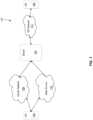
- FIG. 1illustrates a block diagram of a communication system 100 in which various embodiments of the present disclosure may be implemented.
- a client device 102is connected to a server 104 through a plurality of communication networks, which are depicted in FIG. 1 as carrier network 108 and data network 110 .
- the server 104communicates with a second client device 106 through another communication network in the form of a Session Initiation Protocol (SIP) network 112 .
- SIPSession Initiation Protocol
- communication networks 108 , 110 and 112are illustrated, in other embodiments, more are contemplated.
- client devices 102 and 106are illustrated, more are contemplated, as embodiments of the disclosure are capable of coordinating a communication session between a plurality of participants.
- SIP network 112could be replaced with more than one network similar to carrier network 108 and data network 110 .
- the dynamics between the client device 102 and carrier network 108 and data network 110will generally be described in relation to client device 102 ; however, similar functionality may be included with client device 106 .
- the client devices 102 and 106may be a mobile device such as a smart phone, a tablet computer, a laptop computer, a watch with a computer operating system, a personal digital assistant (PDA), a video game console, a wearable or embedded digital device(s), or any one of a number of additional devices with wireless communications capability.
- a mobile devicesuch as a smart phone, a tablet computer, a laptop computer, a watch with a computer operating system, a personal digital assistant (PDA), a video game console, a wearable or embedded digital device(s), or any one of a number of additional devices with wireless communications capability.
- PDApersonal digital assistant
- communication networks 108 and 110are generally wireless networks.
- Example networksinclude but are not limited to Wide Area Networks (WAN) such as a Long Term Evolution (LTE) network, a Global System for Mobile Communications (GSM) network, a Code Division Multiple Access (CDMA) network, a Wideband Code Division Multiple Access (WCDMA), Wireless Local Area Networks (WLAN) such as the various IEEE 802.11 standards, or any other kind of carrier and data networks.
- WANWide Area Networks
- LTELong Term Evolution
- GSMGlobal System for Mobile Communications
- CDMACode Division Multiple Access
- WCDMAWideband Code Division Multiple Access
- WLANWireless Local Area Networks
- the communication networks 108 and 110allow the client device 102 to communicate with the server 104 .
- client device 102may transmit information to the server 104 and receive information from the server 104 .
- communication networks 108 and 110may each separately include a set of cell towers, as well as a set of base stations and/or mobile switching centers (MSCs) communicating over a cellular carrier Public Switch Telephone Network (PSTN).
- the communication networks 108 and 110may include various cell tower/base station/MSC arrangements over a cellular data network.
- carrier network 108is a WAN such as a cellular carrier network providing network access over a 2G, 3G, or 4G network, such as GSM, WCDMA, or LTE, respectively, communicating over either a PSTN or data network.
- data network 110is a WLAN data network operating under one of the IEEE 802.11 standards.
- coverage for the carrier network 108may degrade as client device 102 enters a building. However, wireless coverage inside the building may be adequate over data network 110 . Therefore, client device 102 will have constant wireless access when transitioning between good and bad coverage for both carrier network 108 and data network 110 .
- server 104is configured to receive and transmit a voice data signal, such as that associated with a Voice over Internet Protocol (VoIP) call or a carrier network voice call, between client device 102 and client device 106 through the various networks 108 , 110 and 112 . Therefore, a caller using client device 102 may place a phone call to client device 106 through server 104 .
- client device 102connects to one of the carrier network 108 , the data network 110 , or both simultaneously to relay a data signal associated with the phone call to the server 104 .
- Server 104then places a phone call to client device 106 over SIP network 112 .
- Server 104knows to call the client device 106 by using information identifying client device 106 sent in the data signal associated with the phone call.
- server 104transmits and receives voice data
- server 104may be configured to handle any type of data such as multimedia data including audio, video, pictures, and text data and share that data among the participants in the communication session.
- FIG. 2a block diagram of basic functional components for the client device 102 of FIG. 1 , according to one aspect of the disclosure, is illustrated.
- the client device 102includes one or more processors 202 , memory 204 , a network interface(s) 206 , one or more storage devices 208 , power source 210 , one or more output devices 212 , one or more input devices 214 , a network monitor 218 , and a dialer module 220 .
- the client device 102also includes an operating system 216 .
- Each of the components including the processor 202 , memory 204 , network interface 206 , storage device 208 , power source 210 , output device 212 , input device 214 , network monitor 218 , dialer module 220 and the operating system 216are interconnected physically, communicatively, and/or operatively for inter-component communications.
- client device 106may be equipped with similar functionality.
- the functionalitywill be described in relation to client device 102 , but in certain embodiments client device 106 is equipped with similar functionality.
- processor 202is configured to implement functionality and/or process instructions for execution within client device 102 .
- processor 202executes instructions stored in memory 202 or instructions stored on a storage device 204 .
- Memory 202which may be a non-transient, computer-readable storage medium, is configured to store information within client device 102 during operation.
- memory 202includes a temporary memory, an area for information not to be maintained when the client device 102 is turned off. Examples of such temporary memory include volatile memories such as random access memories (RAM), dynamic random access memories (DRAM), and static random access memories (SRAM).
- RAMrandom access memories
- DRAMdynamic random access memories
- SRAMstatic random access memories
- Storage device 204also includes one or more non-transient computer-readable storage media.
- the storage device 204is generally configured to store larger amounts of information than memory 202 .
- the storage device 204may further be configured for long-term storage of information.
- the storage device 204includes non-volatile storage elements.
- Non-limiting examples of non-volatile storage elementsinclude magnetic hard discs, optical discs, floppy discs, flash memories, or forms of electrically programmable memories (EPROM) or electrically erasable and programmable (EEPROM) memories.
- the client device 102uses network interface(s) 206 to communicate with external devices via one or more networks, such as the communication networks 108 and 110 of FIG. 1 .
- Network interface(s) 206may be a network interface card, such as an Ethernet card, an optical transceiver, a radio frequency transceiver, or any other type of device that can send and receive information.
- Other non-limiting examples of network interfacesinclude Bluetooth®, 2G, 3G, 4G and Wi-Fi radios in client computing devices, and USB.
- the client device 102includes one or more input devices 214 .
- Input devices 214are configured to receive input from a user or a surrounding environment of the user through tactile, audio, and/or video feedback.
- Non-limiting examples of input device 214include a presence-sensitive screen, a mouse, a keyboard, a voice responsive system, video camera, microphone or any other type of input device.
- a presence-sensitive screenincludes a touch-sensitive screen.
- One or more output devices 212are also included in client device 102 .
- Output devices 212are configured to provide output to a user using tactile, audio, and/or video stimuli.
- Output device 212may include a display screen (part of the presence-sensitive screen), a sound card, a video graphics adapter card, or any other type of device for converting a signal into an appropriate form understandable to humans or machines.
- Additional examples of output device 212include a speaker such as headphones, a cathode ray tube (CRT) monitor, a liquid crystal display (LCD), or any other type of device that can generate intelligible output to a user.
- CTRcathode ray tube
- LCDliquid crystal display
- the client device 102includes one or more power sources 210 to provide power to the device.
- power source 210include single-use power sources, rechargeable power sources, and/or power sources developed from nickel-cadmium, lithium-ion, or other suitable material.
- the client device 102includes an operating system 216 .
- the operating system 216controls operations of the components of the client device 102 .
- the operating system 216facilitates the interaction of the processor(s) 202 , memory 204 , network interface 206 , storage device(s) 208 , input device 214 , output device 212 , power source 210 , network monitor 218 and dialer module 220 .
- the client device 102further includes a network monitor module 218 .
- the network monitor module 218keeps track of the signal quality of the various wireless communication networks connected to the client device 102 through the network interface(s) 206 .
- the network monitor module 218would monitor the available signal quality from the carrier network 108 and the data network 110 .
- the network monitor module 218would track whether the signal quality was decreasing or increasing for both networks 108 and 110 . Based on the detected signal quality, the network monitor module 218 informs the client device 102 whether a phone call should be initiated over carrier network 108 or data network 110 . For example, the network monitor module 218 may decide that only the carrier network 108 needs to be used for a phone call because its signal quality is adequate. However, if the signal quality of the carrier network 108 drops, which can be detected generally based on signal strength when a voice call is not active or by actually tracking the performance of the voice call, the network monitor module 218 may determine to use the data network 110 in addition to the carrier network 108 . If the phone call is then determined to be operating adequately over the data network 110 and the location of the client device 102 is relatively stable, then the network monitor module 218 may determine to only use the data network 110 and terminate the call over the carrier network 108 .
- the network monitor module 218may decide to use one of the carrier network 108 or data network 110 based on the increased signal strength of that network. For instance, if client device 102 is already connected over the data network 110 but the network monitor module 218 notices an increase in signal quality from carrier network 108 , the network monitor module 218 may instruct the client device 102 to connect over the carrier network 108 even though no degradation of the data network 110 has occurred.
- the network monitor module 218may have access to information regarding the historical performance of the carrier network 108 or data network 110 within the current geographic area in which the client device 102 may be located. In this embodiment, the network monitor module 218 may decide to connect to one of the carrier network 108 or data network 110 based on this expected signal quality of the respective networks.
- the network monitor module 218continues to track the signal quality of networks 108 and 110 . In this manner, the network monitor module 218 can determine whether the signal quality of the network currently in use is increasing or decreasing and whether a suitable or even preferable alternative network exists based on the actual signal quality or expected signal quality of the alternative networks and the current network.
- the network monitor module 218may collect further information pertaining to both the PSTN and a data network associated with the carrier network 108 . Based on the further information collected regarding the carrier network 108 , the network monitor module 218 will make a recommendation on whether a phone call should be placed over the cellular carrier PSTN or whether the phone call should be placed over the data network using an Internet Protocol (IP) based communication scheme such as the VoIP.
- IPInternet Protocol
- an additional function of the network monitor module 218is to determine whether the communication network(s) currently being used can support High Definition (HD) voice or video. Conducting a phone call using HD voice or video requires higher bandwidth than a typical voice call. Therefore, the network monitor module 218 provides an indication of whether a communication network(s) is capable of supporting HD voice or video such that a call can be either be initiated or upgraded to HD voice or a video call.
- HDHigh Definition
- the client device 102further includes a dialer module 220 .
- the dialer module 220uses the network recommendation from the network monitor module 218 to place a phone call over either network 108 or 110 .
- the network monitor module 218may have advised to use the carrier network 108 .
- the dialer module 220would place the phone call over the carrier network 108 and may further decide to use either the voice channel over the PSTN to make a regular phone call or it may use a cellular data channel to make a VoIP call, as determined by the network monitor module 218 .
- the dialer module 220places a second phone call over the data network 110 to the same recipient of the original phone call.
- the second phone callis a VoIP call based on the same input into the client device 102 as the original phone call.
- the dialer module 220may determine that the data network 110 is stable enough such that the second phone call may be maintained solely by the data network 110 and drop the original phone call over the carrier network 108 .
- the network monitor module 218may determine that the signal quality of the carrier network 108 has improved and therefore the second call over the data network 110 may be dropped.
- the dialer module 220will instruct the client device 102 to be in one of three calling conditions.
- the first conditionis a phone call over a single communication network such as carrier network 108 or data network 110 .
- the second conditionis two separate phone calls with one phone call over a first network such as the carrier network 108 and the other phone call over a second network such as the data network 110 .
- the third conditionis a transition from two active phone calls to a single phone call over whichever network (carrier network 108 or data network 110 ) the network monitor module 218 determines is most suitable for the phone call.
- Server 104runs a central service interposed in the signaling paths of inbound and outbound phone calls from and to client devices, such as client device 102 and client device 106 (see FIG. 1 ).
- the server 104includes one or more processors 302 , memory 304 , network interface(s) 306 , one or more storage devices 308 , a media mixing module 310 , a media session data joining module 312 , and a connection service module 314 .
- each of the componentsincluding the processor(s) 302 , memory 304 , network interface(s) 306 , storage device(s) 308 , media mixing module 310 , media session data joining module 312 , and connection service module 314 are interconnected physically, communicatively, and/or operatively for inter-component communications.
- processors 302are configured to implement functionality and/or process instructions for execution within the server 104 .
- processors 302execute instructions stored in memory 304 or instructions stored on storage devices 308 .
- Memory 304which may be a non-transient, computer-readable storage medium, is configured to store information within server 104 during operation.
- memory 304includes a temporary memory, i.e. an area for information not to be maintained when the server 104 is turned off. Examples of such temporary memory include volatile memories such as random access memories (RAM), dynamic random access memories (DRAM), and static random access memories (SRAM).
- RAMrandom access memories
- DRAMdynamic random access memories
- SRAMstatic random access memories
- Storage devices 308also include one or more non-transient computer-readable storage media. Storage devices 308 are generally configured to store larger amounts of information than memory 304 . Storage devices 308 may further be configured for long-term storage of information.
- storage devices 304include non-volatile storage elements. Non-limiting examples of non-volatile storage elements include magnetic hard discs, optical discs, floppy discs, flash memories, or forms of electrically programmable memories (EPROM) or electrically erasable and programmable (EEPROM) memories.
- the server 104uses network interface(s) 306 to communicate with external devices via one or more networks, such as the carrier network 108 or the data network 110 of FIG. 1 .
- networksmay also include one or more wireless networks, wired networks, fiber optics networks, and other types of networks through which communication between the server 104 and an external device may be established.
- Network interface(s) 306may be a network interface card, such as an Ethernet card, an optical transceiver, a radio frequency transceiver, or any other type of device that can send and receive information.
- the server 104includes the media mixing module 310 , which runs a media mixing service that coordinates the signaling from a plurality of client devices participating in a communication session via server 104 .
- the media mixing serviceis a central service receiving individual data signals from each of the plurality of client devices, such as client devices 102 and 106 (see FIG. 1 ), participating in a communication session through server 104 .
- the media mixing servicethen mixes the data signals received from each of the plurality of client devices such that the media transmitted over the data signals is shared among the plurality of client devices.
- client device 102 and client device 106each transmit a data signal containing media to be shared in the communication session.
- the media mixing module 310receives the data signals from each of client device 102 and client device 106 and relays the media contained in the data signals to the recipient device.
- the mediamay be audio, video, text, or images.
- the media mixing module 310is capable of operating with more than two client devices participating in a communication session.
- the media mixing module 310is capable of controlling system resources of the server 104 such that for low data rate communication sessions only a minimal amount of system resources are utilized. For example, if there are only two participants in a communication session, and the media transmitted in the data signals from each of the two participants is audio data, then the media mixing module 310 will instruct the server 104 to utilize a minimal amount of system resources. During the communication session between the two participants, if the media switches to video or several additional participants join the communication session, then the media mixing module 310 will instruct the server 104 to use more system resources to support the communication session.
- the server 104includes a media session data joining module 312 , which runs a data joining service.
- the data joining serviceoperates in conjunction with the media mixing service to allow a client device participating in a communication session (such as client devices 102 and 106 from FIG. 1 ) to locate and join the communication session over a data network, such as data network 110 .
- client device 102see FIG. 1
- the data joining servicefacilitates client device 102 placing a redundant phone call over the data network 110 .
- the same data signalis transmitted from client device 102 over both the carrier network 108 and the data network 110 .
- the data joining serviceutilizes a variety of techniques to facilitate placement of a redundant phone call over the data network 110 .
- One such techniqueis to send a message containing an identifier of the communication session to a client device, such as client device 102 , after receiving indication that the client device 102 is switching networks, as discussed above in relation to FIG. 2 .
- Client device 102then places the redundant phone call over the data network, such as data network 110 , to the server 104 , which then joins the phone call to the communication session.
- the client device 102may make the decision to terminate the original phone call, as discussed above.
- This messagemay be implemented using a mobile push notification service.
- a second technique used to facilitate placement of a redundant phone call from a client device, such as client device 102 , participating in a communication session through the server 104is a network Application Programming Interface (API) provided by the data joining service.
- the APIis configured to provide an identifier of the communication session to the client device 102 upon query from the client device 102 .
- the APIknows determines the identifier based on a query of the client device's 102 call currently in progress.
- the client device 102then utilizes the identifier to locate and join the communication session over a redundant phone call. Once the redundant phone call is joined to the communication session, the client device 102 may make the decision to terminate the original phone call.
- the server 104includes a connection module 314 , which runs a connection service.
- the connection serviceoperates in conjunction with the media mixing service of the media mixing module 310 to allow a client device participating in a communication session (such as client devices 102 and 106 from FIG. 1 ) to locate and join the communication session over a carrier network, such as carrier network 108 .
- a client device participating in a communication sessionsuch as client devices 102 and 106 from FIG. 1
- the connection servicefacilitates client device 102 placing a redundant phone call over the carrier network 108 .
- the same data signalis transmitted from client device 102 over both the carrier network 108 and the data network 110 .
- the connection serviceutilizes a variety of techniques to facilitate placement of a redundant phone call over the carrier network 108 .
- One such techniqueis to send a message containing a connection phone number for the communication session to a client device, such as client device 102 .
- the client device 102places the redundant phone call over the carrier network 108 to the server 104 using the connection phone number, which then joins the phone call to the communication session.
- the client device 102may make the decision to terminate the original phone call.
- This messagemay be implemented using a mobile push notification service.
- a second technique used to facilitate placement of a redundant phone call from a client device, such as client device 102 , participating in a communication session through the server 104is a number request via a phone call to a controlled phone number of the server 104 .
- the controlled phone numbercalls the media mixing service of the media mixing module 310 directly, and the media mixing service instructs the connection service to provide a phone number for the ongoing communication session.
- the client devicecalls the phone number provided by the connection service over the carrier network 108 in order to locate and join the communication session through a redundant phone call. Once the redundant phone call is joined to the communication session, the client device 102 may make the decision to terminate the original phone call.
- a client devicesuch as client device 102
- client device 102is able to place a redundant phone call over a carrier network, such as carrier network 108 , to the server 104 without utilizing the connection service.
- the client device 102is preprogrammed with at least one phone number that calls the media mixing module 310 of server 104 directly.
- the media mixing module 310receives a phone call over this preprogrammed number it reads the caller identification information to determine whether client device 102 is currently participating in a communication session. The media mixing module then connects the redundant phone call to the communication session. Once the redundant phone call is joined to the communication session, the client device 102 may make the decision to terminate the original phone call.
- the server 104 depicted in FIG. 3is representative of a physical embodiment of a server. However, the server 104 may be implemented as a virtual server such as a cloud server.
- Server 104is configured to receive a data signal associated with a phone call placed from client devices, such as client devices 102 and 106 (see FIG. 1 ) over a communication network via outbound call interception techniques.
- client devicessuch as client devices 102 and 106 (see FIG. 1 )
- the server 104is configured to receive the data signal from either a carrier network 108 or a data network 110 , but in other embodiments, more than two networks are contemplated.
- Shadow number callingrequires the dialer module 220 to call a reserved shadow phone number that connects directly to the media mixing module 310 of server 104 instead of the number entered by the user.
- the dialer module 220then provides the user entered number of the recipient client device, such as client device 106 and the client device's 102 own phone number to the media mixing module 310 .
- the media mixing module 310then places a separate phone call to the recipient client device 106 and then joins the two phone calls into a communication session.
- server 104Another technique used by server 104 for outbound call interception is network integration. Using this technique, both the carrier network 108 and the data network 110 know when it receives an initiation request for a phone call from the dialer module 220 of client device 102 to relay the data signal associated with the phone call to the media mixing module 310 of server 104 . The media mixing module 310 then places a phone call to the recipient client device 106 and joins the two phone calls into a communication session. The media mixing module 310 uses identification information in the data signal to place a phone call to the recipient client device 108 (see FIG. 1 ). In the embodiment illustrated in FIG. 1 , this phone call is a VoIP phone call over SIP network 112 . After placing the phone call, the media mixing module 310 then completes the communication session by sending the data signal associated with the phone call from client device 102 over the VoIP phone call to the recipient client device 106 .
- Server 104is further configured to receive a data signal associated with a phone call placed to the client device 102 (see FIG. 1 ) over a communication network via inbound call interception techniques.
- the server 104is configured to receive the data signal from either a carrier network 108 or a data network 110 , but in other embodiments, more than two networks are contemplated.
- Service number callingrequires a user provide a service number as a primary point of contact.
- the service numbercalls the media mixing module 310 of server 104 directly as opposed to the user's associated client device.
- the media mixing module 310knows the user associated with the service number and places a separate phone call to the user's associated client device, such as client device 102 .
- the media mixing module 310then joins the two phone calls into a communication session.
- the media mixing module 310can call more than one device associated with the user based on the service number. In this manner, the user can be reached via multiple points of contact.
- server 104Another technique used by server 104 for inbound call interception is network integration. Using this technique, both the carrier network 108 and the data network 110 know when it receives an initiation request for a phone call to client device 102 to relay the data signal associated with the phone call to the media mixing module 310 of server 104 rather than directly to client device 102 . The media mixing module 310 then places a phone call to client device 102 and joins the two phone calls into a communication session.
- the media mixing module 310 of server 104controls the signaling between a plurality of client devices involved in a communication session such as a multi-party video conference, which is not initiated by dialing a phone number. In this situation, the plurality of client devices join the conference directly through the server 104 and the media mixing module 310 controls the signaling therebetween. In this manner, there is no need for an outbound or inbound interception technique because no phone number is being dialed by the client device.
- both data signals (original and redundant) associated with the phone callswill be relayed to the media mixing module 310 of the server 104 .
- the media mixing module 310will realize that both data signals are from the same client device and should be directed to the same recipient device 106 based on identification information in the data signals such as a phone number associated with the recipient client device 106 .
- the media mixing module 310uses both data signals associated with the phone calls to synthesize a best quality data signal, which it then sends to the recipient client device 106 over the separate phone call established when the original phone call was first initiated.
- One technique the media mixing module 310 uses to synthesize a best quality data signalrelies on the two separate data signals carrying the same data because they are associated with the same input into the client device 102 . Specifically, to synthesize the best quality data signal the media mixing module 310 will merely send the data signal that is received at the server 104 first and discard the other.
- Another technique to produce a best quality data signalis for the dialer module 220 to split the data signal based on the singular input into the client device 102 and send part of the data over each communication network, such as the carrier network 108 and the data network 110 .
- Splitting the data signalis advantageous because it increases the bandwidth available for the data signal. This may be done in situations where the network monitor module 218 notices stable signal quality from both the carrier network 108 and the data network 110 .
- the media mixing module 310must know how the dialer module 220 is splitting the data among the two networks 108 and 110 such that it can reconstruct the data signal and send it to the recipient client device 106 .
- one methodis to use a scalable coding technique where the data signal is split into a base layer and a high quality incremental layer.
- the base layer of the data signalwould be sent over one network and the incremental layer would be sent over the other network.
- Another technique to split the data signalis to send alternate packets over each network connection. For example, a first packet of the data signal could be sent over the carrier network 108 and a second packet could be sent over the data network 110 .
- the media mixing module 310is configured to transmit this data signal back to the client device 102 over whichever network connection is active. Specifically, in the scenario where only a single communication network such as the carrier network 108 is active, the media mixing module 310 will send the data signal received from the recipient device 106 to the client device 102 over the carrier network 108 . In the situation where both the carrier network 108 and the data network 110 are active, the media mixing module 310 will reproduce the data signal received from the recipient client device 106 and send over both communication networks 108 and 110 . Client device 102 will then receive the same data signal over each of the carrier network 108 connection and the data network 110 connection. The client device 102 will reproduce the singular data signal from the recipient client device 106 by utilizing whichever packet is received first and discarding the redundant packet from the other network.
- connection between the client device 102 and the recipient client device 106can be maintained even when switching between the communications networks 108 and 110 . This is because no matter whether the connection to the client device 102 is over the carrier network 108 or the data network 110 , the media mixing module 310 will maintain the call to the recipient client device 106 and just complete the communication over whichever communication network 108 or 110 the client device 102 is currently communicating with.
- the server 104is an intermediary entity between the client device 102 and the recipient client device 106 , if the client device 102 is connected over the carrier network 108 and the call from the client device 102 to the server 104 drops, the media mixing module 310 of server 104 will be able to tell whether the recipient client device 106 hung up or whether the network inadvertently dropped the call.
- the media mixing module 310can make this determination because if it is a carrier network 108 failure that causes the call to end, then the connection from the server 104 to the recipient client device 106 would still be active. Otherwise, if the recipient client device 106 hung up, the connection to the server 104 would no longer be active. In the event that a network failure is detected, the dialer module 220 of the client device 102 will reestablish the connection to the server 104 , and the server 104 will just resume the connection as it was before the network failure.
- FIG. 4illustrates a flow chart 400 depicting steps performed by the network monitor module 218 (see FIG. 2 ) in conjunction with the dialer module 220 .
- the network monitor module 218will determine the signal quality of first and second network connections (such as communication networks 108 and 110 from FIG. 1 ).
- the network monitor module 218compares the signal quality of the first and second network connections and selects the network connection with the highest signal quality at step 408 .
- the dialer module 220initiates a communication session or in other words a phone call to the server 104 over the selected network connection.
- the network monitor module 218While the phone call is underway, the network monitor module 218 continues to monitor the signal quality of the network connections at step 412 .
- the network monitor module 218determines whether the signal quality of the selected network connection had degraded such that placing a call over the alternative network is advised or that the signal quality of the alternative network has increased such that the alternative network is advised. If the connection has not degraded or the signal quality of the alternative network has not increased, then the dialer module 220 will just maintain the phone call at step 416 . However, if the signal quality of the selected network has degraded or the alternative network signal quality has increased, then the network monitor module 218 will provide a signal quality of the unselected network connection to the dialer module 220 .
- Flow chart 500 illustrated in FIG. 5depicts the steps performed by the dialer module 220 (see FIG. 2 ) based on advice from the network monitor module 218 .
- the dialer module 220initiates a communication session or phone call over the selected network, similar to step 410 of FIG. 4 .
- the dialer module 220relays a data signal associated with the initiated phone call to the server 104 .
- the dialer module 220receives indication that the signal quality of the selected network connection has degraded or the signal quality of an alternative or unselected network has increased.
- the dialer module 220initiates a second communication session or in other words a second phone call over the previously unselected network.
- the dialer module 220relays a second data signal associated with the second phone call to the server 104 (see FIG. 1 ).
- the network monitor 218determines whether the signal quality of one of the network connections has changed such that it will advise to terminate one of the connections. For instance, the signal quality of one network has improved greatly and the signal quality of the other network has degraded significantly. Or the signal quality of just one network has degraded significantly. If the signal quality of both the networks is adequate, then both phone calls are maintained at step 514 . However, if the signal quality of at least one of the networks has changed such that termination is recommended, the dialer module 220 terminates the phone call associated with that network at step 516 .
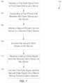
- Flow chart 600 illustrated in FIG. 6depicts the steps performed by the server 104 (see FIG. 1 ) based on receiving a data signal or data signals from the dialer module 220 (see FIG. 2 ) of the client device 102 .
- the server 104receives a first data signal from the dialer module 220 .
- the server 104uses identification information contained in the data signal, the server 104 determines a destination for the data signal, such as recipient client device 106 .
- the server 104places a phone call to the determined destination or in other words, the recipient client device 106 and joins the call from the client device 102 to the call to the recipient client device 106 .
- the server 104checks to see if a second data signal has been received from the dialer module 220 . If not, then the server 104 maintains the communication session between the client device 102 and the recipient client device 106 . If a second data signal has been received from the dialer module 220 , then, at step 612 , the server 104 associates the first data signal with the second data signal. At step 614 , the server 104 synthesizes a best quality voice stream based on the received first and second data signals. At step 616 , the server 104 transmits the best quality data signal over the phone call to the recipient client device 106 . At step 618 , the server 104 receives a return data signal from the recipient client device 106 .
- the server 104transmits a data signal from the recipient client device 106 over both the first and second networks to the client device 102 .
- the server 104checks if the dialer module 220 has terminated one of the phone calls associated with one of the data signals. If no such termination has occurred, then at step 624 the server 104 maintains the communication session between the client device 102 and the recipient client device 106 utilizing both the first and second data signals to synthesize a best quality data signal to send to the recipient client device 106 .
- the server 104maintains the communication session between the client device 102 and the recipient client device 106 using only the remaining data signal from the client device 102 .
- Flow chart 700 illustrated in FIG. 7depicts the steps performed by the server 104 (see FIG. 1 ) based on receiving a data signal from the dialer module 220 (see FIG. 2 ) of the client device 102 .
- Flow chart 700is similar to flow chart 600 (see FIG. 6 ) but contains more specificity regarding operation of the media mixing module 310 .
- the server 104receives a first data signal from client device 102 at a media mixing module 310 of the server.
- the data signalcontains media data from client device 102 and an identifier of a recipient client device, such as client device 106 .
- the server 104conducts a first phone call between client device 102 and the media mixing module 310 of the server 104 based on the first data signal received from the client device 102 .
- the media mixing module 310initiates a second phone call from the media mixing module 310 of the server 104 to the recipient client device 106 based on the identifier contained in the data signal from client device 102 .
- the media mixing module 310connects the recipient client device 106 to the media mixing module of the server over the second phone call.
- server 104receives a second data signal from the recipient client device 106 at the media mixing module 310 of the server 104 .
- the second data signalcontains media data from the second client device.
- the media mixing module 310joins the first data signal from client device 102 and the second data signal from the recipient client device 106 in a media mixing communication session. In this manner, the media mixing module 310 coordinates the media contained in the first and second data signals between client device 102 and client device 106 .
- Flow chart 800 illustrated in FIG. 8depicts the steps performed by the server 104 (see FIG. 1 ) based on receiving an indication of a request to move at least one of the first data signal or second data signal (see FIG. 7 ) to one of the carrier network 108 or the data network 110 (see FIG. 1 ).
- Flow chart 800is similar to flow chart 500 (see FIG. 5 ), but flow chart 800 illustrates the steps taken from the perspective of the modules running on server 104 .
- the media mixing module 310 of the server 104receives a request to move to either carrier network 108 or data network 110 from either or both of the client device 102 or the client device 106 .
- the media mixing module 310sends an identifier of the ongoing media mixing communication session (see FIG. 7 ) to the client device that sent the request to move.
- the media mixing module 310receives a third phone call transmitting a third data signal redundant to the data signal from the client device that sent the request to move over either the carrier network or the data network.
- the choice of whether to move to the carrier network or the data networkis performed by the client device, such as client device 102 .
- the client device 102will make this decision based on network quality and capacity for the desired data to be shared during the communication session. If client device 102 requests to move to the data network 110 , then the media session data joining module 312 (see FIG. 3 ) is utilized to assist in the move. And if the client device 102 requests to move to the carrier network 108 , then the connection service module 314 (see FIG. 3 ) is utilized to assist in the move.
- the media mixing module 310joins the third data signal to the media mixing communication session over either the carrier network or the data network, as requested by client device 102 .
- the third data signalis redundant to either the first or second data signals, depending on which client device (either client device 102 or 106 ) decided to move. As described in FIG. 5 above, the client device 102 or 106 then decides whether to maintain both transmitted data signals or to terminate one of the data signals.
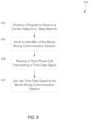
- Flow chart 900 illustrated in FIG. 9depicts the steps performed by the media mixing module 310 of the server 104 (see FIG. 1 ) based on receiving a request to change an ongoing communication session to a multimedia communication session, such as a video call.
- the media mixing module 310receives a request to switch from an audio data based communication session to a multimedia data based communication session, such as a video call.
- the media mixing module 310receives an indication of whether the network the client device is currently communicating over is capable of transmitting multimedia data such as video data.
- the media mixing module 310will receive the multimedia data from the client device, at step 906 , and then proceed to share the multimedia data with other client devices associated with the communication session at step 908 . If the current network is not capable of transmitting multimedia data, then the client device checks if a more suitable network is available. If a more suitable network is not available, then the request to transmit multimedia data is denied at step 912 . If a more suitable network is available, then a request to move to the more suitable network is performed at step 914 . Moving to a new network is performed as described in FIG. 8 .
- the media mixing module 310 of server 104shares the multimedia data over the media mixing communication session at step 908 . In this manner, the media mixing module 310 coordinates the signaling between each participating client device in the media mixing communication session.
Landscapes
- Engineering & Computer Science (AREA)
- Multimedia (AREA)
- Signal Processing (AREA)
- Computer Networks & Wireless Communication (AREA)
- Business, Economics & Management (AREA)
- General Business, Economics & Management (AREA)
- Telephonic Communication Services (AREA)
- Data Exchanges In Wide-Area Networks (AREA)
Abstract
Description
Claims (20)
Priority Applications (1)
| Application Number | Priority Date | Filing Date | Title |
|---|---|---|---|
| US16/657,205US11695874B2 (en) | 2013-09-27 | 2019-10-18 | System and method for increased call quality and success rate |
Applications Claiming Priority (3)
| Application Number | Priority Date | Filing Date | Title |
|---|---|---|---|
| US201361883644P | 2013-09-27 | 2013-09-27 | |
| US14/140,913US10491749B2 (en) | 2013-09-27 | 2013-12-26 | System and method for increased call quality and success rate |
| US16/657,205US11695874B2 (en) | 2013-09-27 | 2019-10-18 | System and method for increased call quality and success rate |
Related Parent Applications (1)
| Application Number | Title | Priority Date | Filing Date |
|---|---|---|---|
| US14/140,913ContinuationUS10491749B2 (en) | 2013-09-27 | 2013-12-26 | System and method for increased call quality and success rate |
Publications (2)
| Publication Number | Publication Date |
|---|---|
| US20200053222A1 US20200053222A1 (en) | 2020-02-13 |
| US11695874B2true US11695874B2 (en) | 2023-07-04 |
Family
ID=52741231
Family Applications (3)
| Application Number | Title | Priority Date | Filing Date |
|---|---|---|---|
| US14/140,953Active2034-05-14US10097694B1 (en) | 2013-09-27 | 2013-12-26 | Method and system for moving phone call participation between carrier and data networks |
| US14/140,913Active2035-04-21US10491749B2 (en) | 2013-09-27 | 2013-12-26 | System and method for increased call quality and success rate |
| US16/657,205Active2034-02-05US11695874B2 (en) | 2013-09-27 | 2019-10-18 | System and method for increased call quality and success rate |
Family Applications Before (2)
| Application Number | Title | Priority Date | Filing Date |
|---|---|---|---|
| US14/140,953Active2034-05-14US10097694B1 (en) | 2013-09-27 | 2013-12-26 | Method and system for moving phone call participation between carrier and data networks |
| US14/140,913Active2035-04-21US10491749B2 (en) | 2013-09-27 | 2013-12-26 | System and method for increased call quality and success rate |
Country Status (8)
| Country | Link |
|---|---|
| US (3) | US10097694B1 (en) |
| EP (1) | EP3050351B1 (en) |
| KR (2) | KR102170200B1 (en) |
| CN (2) | CN110996344B (en) |
| AU (1) | AU2014324809C1 (en) |
| BR (1) | BR112016006700B1 (en) |
| CA (1) | CA2925109C (en) |
| WO (1) | WO2015048439A1 (en) |
Families Citing this family (11)
| Publication number | Priority date | Publication date | Assignee | Title |
|---|---|---|---|---|
| US10496977B2 (en) | 2012-07-16 | 2019-12-03 | Square, Inc. | Storing and forwarding payment transactions |
| US10097694B1 (en)* | 2013-09-27 | 2018-10-09 | Google Llc | Method and system for moving phone call participation between carrier and data networks |
| US10037521B1 (en)* | 2014-09-24 | 2018-07-31 | Square, Inc. | Background communication failover for mobile payments |
| US11057285B2 (en)* | 2014-11-24 | 2021-07-06 | ZPE Systems, Inc. | Non-intrusive IT device monitoring and performing action based on IT device state |
| US9881302B1 (en) | 2014-12-11 | 2018-01-30 | Square, Inc. | Intelligent payment capture in failed authorization requests |
| US10298561B2 (en)* | 2015-06-30 | 2019-05-21 | Vmware, Inc. | Providing a single session experience across multiple applications |
| US10091264B2 (en) | 2015-12-26 | 2018-10-02 | Intel Corporation | Technologies for streaming device role reversal |
| US10366378B1 (en) | 2016-06-30 | 2019-07-30 | Square, Inc. | Processing transactions in offline mode |
| EP3488635B1 (en) | 2016-07-22 | 2020-09-02 | Google LLC | Mobility in a multi-network wireless system |
| CN110832950B (en) | 2017-07-05 | 2023-06-23 | 瑞典爱立信有限公司 | Method of operating a wireless communication device and associated device and apparatus |
| US11503526B2 (en)* | 2020-09-15 | 2022-11-15 | International Business Machines Corporation | Predictive communication compensation |
Citations (99)
| Publication number | Priority date | Publication date | Assignee | Title |
|---|---|---|---|---|
| EP0244501A1 (en) | 1985-02-14 | 1987-11-11 | Ranco Incorporated of Delaware | Temperature sensing circuit |
| US6128490A (en) | 1997-05-08 | 2000-10-03 | Nortel Networks Limited | Wireless communication system that supports selection of operation from multiple frequency bands and multiple protocols and method of operation therefor |
| US20010002192A1 (en)* | 1999-11-30 | 2001-05-31 | Nec Corporation | Communication connection merge method and node to be used therefor |
| US20020010866A1 (en)* | 1999-12-16 | 2002-01-24 | Mccullough David J. | Method and apparatus for improving peer-to-peer bandwidth between remote networks by combining multiple connections which use arbitrary data paths |
| US6381315B1 (en) | 1999-12-02 | 2002-04-30 | Eli Nhaissi | Universal exchange for making least-cost non-local telephone calls |
| WO2002041580A1 (en) | 2000-11-14 | 2002-05-23 | Siemens Aktiengesellschaft | Device and method for selecting network accesses |
| US20020169716A1 (en) | 2001-05-08 | 2002-11-14 | Johnson Jack J. | Bidding tor telecommunications traffic and billing for service |
| US6633761B1 (en) | 2000-08-11 | 2003-10-14 | Reefedge, Inc. | Enabling seamless user mobility in a short-range wireless networking environment |
| WO2004047476A1 (en) | 2002-11-20 | 2004-06-03 | International Business Machines Corporation | Managing network resources for wireless communication |
| US20040246920A1 (en) | 2003-06-03 | 2004-12-09 | Nokia Corporation | Transmission of pricing information in telecommunication system |
| US20050180338A1 (en) | 2004-02-17 | 2005-08-18 | Nokia Corporation | Swapping voice and video calls |
| US20050245269A1 (en) | 2004-04-30 | 2005-11-03 | Intel Corporation | Channel scanning in wireless networks |
| US20050276406A1 (en) | 2004-06-10 | 2005-12-15 | International Business Machines Corporation | System and method for conference call initialization |
| WO2006005947A1 (en) | 2004-07-12 | 2006-01-19 | Sensustech Limited | Testing device and method |
| US20060098625A1 (en) | 2004-11-10 | 2006-05-11 | Cisco Technology, Inc. | Method for managing the quality of encrypted voice over IP to teleagents |
| US20060193295A1 (en) | 2004-11-19 | 2006-08-31 | White Patrick E | Multi-access terminal with capability for simultaneous connectivity to multiple communication channels |
| US20060294244A1 (en)* | 2005-06-24 | 2006-12-28 | Naqvi Shamim A | Digital home networks having a control point located on a wide area network |
| US20060291487A1 (en)* | 2005-06-24 | 2006-12-28 | Aylus Networks, Inc. | IMS networks with AVS sessions with multiple access networks |
| US20070037550A1 (en) | 2005-04-29 | 2007-02-15 | Frederic Rassam | System and process for switching between cell phone and landline services |
| US7180898B2 (en) | 2000-11-20 | 2007-02-20 | Hitachi, Ltd. | Communication system |
| US20070064894A1 (en) | 2005-09-14 | 2007-03-22 | Armstrong Edward F | Method, system and device for relay call transfer service |
| US20070064684A1 (en) | 2005-08-24 | 2007-03-22 | Kottilingal Sudeep R | Interleaving VoIP/VIP transmission in multiple sessions to increase quality of service in mobile devices having multiple interfaces |
| US20070127391A1 (en) | 2001-05-14 | 2007-06-07 | Level 3 Communications, Inc. | Service Level Agreements Based on Objective Voice Quality Testing for Voice Over IP (VOIP) Networks |
| US20070147317A1 (en) | 2005-12-23 | 2007-06-28 | Motorola, Inc. | Method and system for providing differentiated network service in WLAN |
| CN101009650A (en) | 2006-01-03 | 2007-08-01 | 阿尔卡特朗讯公司 | Method for providing seamless session mobility |
| CN101018400A (en) | 2006-02-07 | 2007-08-15 | 华为技术有限公司 | A system and method for realizing call service based on voice service continuity |
| US20080002668A1 (en) | 2006-06-30 | 2008-01-03 | Sony Ericsson Mobile Communications Ab | Portable communication device and method for simultaneously |
| US20080009279A1 (en) | 2006-07-10 | 2008-01-10 | Kozo Sakawa | Radio Service Area Quality Information Acquisition System |
| EP1885144A2 (en) | 2006-07-31 | 2008-02-06 | Fujitsu Ltd. | Handover between a cellular network and a wireless LAN |
| US20080107051A1 (en) | 2006-11-07 | 2008-05-08 | Mediatek Inc. | System and method for operating a portable electronic device |
| US20080233977A1 (en) | 2007-03-21 | 2008-09-25 | General Instrument Corporation | Method, Device and System for Accessing Mobile Device User Information |
| US7433929B2 (en) | 2000-12-29 | 2008-10-07 | At&T Mobility Ii Llc | Intelligent network selection based on quality of service and applications over different wireless networks |
| US20090061862A1 (en) | 2007-08-30 | 2009-03-05 | Alberth Jr William P | Peer to peer service discovery sharing |
| US7509131B2 (en) | 2004-06-29 | 2009-03-24 | Microsoft Corporation | Proximity detection using wireless signal strengths |
| CN101420375A (en) | 2007-10-25 | 2009-04-29 | 阿尔卡特朗讯公司 | Distribution of shared content streams in communications networks |
| US20090116443A1 (en) | 2006-03-22 | 2009-05-07 | Matthew D Walker | Re-establishing wireless communication sessions |
| US20090157882A1 (en)* | 2007-12-18 | 2009-06-18 | International Business Machines Corporation | Network connection failover during application service interruption |
| US20090168757A1 (en) | 2007-12-31 | 2009-07-02 | Apple Inc. | Transparently routing a telephone call between mobile and voip services |
| US20090201879A1 (en) | 2007-10-29 | 2009-08-13 | Interdigital Technology Corporation | Integration of 802.21 media independent handover functionality to radio interface layer and telephony server |
| US20090298467A1 (en) | 2008-05-27 | 2009-12-03 | Tsaba Zohar | Enabling & charging non-sim devices for broadband (wimax, 3g, gprs) services thru nearby sim devices |
| US20100172323A1 (en) | 2006-12-29 | 2010-07-08 | Nokia Corporation | Method of handover of circuit-switched voice call to packet-switched voice call |
| US7809360B2 (en) | 2006-05-24 | 2010-10-05 | International Business Machines Corporation | Optimization of calendar, itinerary, route plan, and PIM efficiencies according to assimilated wireless service availability conditions |
| US20100287296A1 (en) | 2009-05-08 | 2010-11-11 | Canon Kabushiki Kaisha | Network streaming of a single data stream simultaneously over multiple physical interfaces |
| US20100304737A1 (en) | 2009-05-26 | 2010-12-02 | Jain Puneet K | Techniques for interworking between heterogeneous radios |
| US7848292B2 (en) | 2006-06-29 | 2010-12-07 | Alcatel-Lucent Usa Inc. | Method of dynamically populating a neighbor list in a wireless communication system |
| US20100310062A1 (en) | 2009-06-08 | 2010-12-09 | Microsoft Corporation | Conveying service invocation information within multimodal conversation systems |
| US20110096673A1 (en) | 2009-10-28 | 2011-04-28 | Liveops, Inc. | System and method for adaptive call management |
| CN102100112A (en) | 2008-07-17 | 2011-06-15 | 高通股份有限公司 | Apparatus and method for mobile virtual network operator (mvno) hosting, selecting and pricing |
| US20110216694A1 (en) | 2010-03-03 | 2011-09-08 | Jan Plasberg | Enhanced Circuit-Switched Calls |
| US20110250909A1 (en) | 2010-04-07 | 2011-10-13 | Arun Mathias | Registering client computing devices for online communication sessions |
| US20110269423A1 (en) | 2010-05-03 | 2011-11-03 | Schell Stephan V | Wireless network authentication apparatus and methods |
| US20110306318A1 (en) | 2010-06-14 | 2011-12-15 | Clive Edward Rodgers | Apparatus and methods for provisioning subscriber identity data in a wireless network |
| WO2011162688A1 (en) | 2010-06-21 | 2011-12-29 | Scania Cv Ab | Method and device pertaining to cooling of dosing units of scr systems |
| US20120014271A1 (en) | 2010-07-15 | 2012-01-19 | Damenti Nicholas | Efficient Use of a Communications Network |
| US8107932B1 (en)* | 2008-09-10 | 2012-01-31 | Rockstar Bidco Lp | Enabling mid-call services to be added to a communication session by a wireless device |
| US20120052914A1 (en) | 2002-06-24 | 2012-03-01 | Telcordia Technologies, Inc. | Authenticating Multiple Devices Simultaneously Over a Wireless Link Using a Single Subscriber Identity Module |
| US8131317B2 (en) | 2006-08-28 | 2012-03-06 | Samsung Electronics Co. Ltd | Apparatus and method for downloading SIM data in mobile communication system |
| US8155081B1 (en) | 2007-05-21 | 2012-04-10 | Marvell International Ltd. | Self learning roaming optimization |
| US20120094653A1 (en) | 2010-10-13 | 2012-04-19 | Fujitsu Limited | Mobile communication system, communication control apparatus, communication control method and wireless base station |
| US8165581B2 (en) | 2008-04-25 | 2012-04-24 | Microsoft Corporation | Selective channel scanning for networked devices |
| US20120108206A1 (en) | 2010-10-28 | 2012-05-03 | Haggerty David T | Methods and apparatus for access control client assisted roaming |
| US8200217B2 (en) | 2008-05-23 | 2012-06-12 | Qualcomm Incorporated | Method and apparatus for channel scanning that improves acquisition probability and power consumption |
| US20120178488A1 (en) | 2011-01-09 | 2012-07-12 | Boingo Wireless, Inc. | System, Method and Apparatus for Dynamic Wireless Network Discovery |
| US20120195223A1 (en) | 2009-01-28 | 2012-08-02 | Raleigh Gregory G | Verifiable and Accurate Service Usage Monitoring for Intermediate Networking Devices |
| US20120282915A1 (en) | 2011-05-06 | 2012-11-08 | Verizon Patent And Licensing Inc. | Connecting device via multiple carriers |
| US20130040693A1 (en) | 2011-08-10 | 2013-02-14 | Htc Corporation | Apparatuses and methods for handovers between heterogeneous networks |
| WO2013020598A1 (en) | 2011-08-11 | 2013-02-14 | Nokia Siemens Networks Oy | Optimizing a handover behavior of a mobile radio communication network based on an extended data record being associated with a user equipment |
| US8391192B2 (en) | 2007-05-14 | 2013-03-05 | Qualcomm Incorporated | Carrier switching in a multi-carrier wireless communication network |
| WO2013044359A1 (en) | 2011-09-30 | 2013-04-04 | Tutela Technologies Ltd. | A system for regulating wireless device operations in wireless networks |
| US20130148567A1 (en) | 2011-12-13 | 2013-06-13 | Tzahi Efrati | Systems and methods for handoff of a mobile telephone call in a voip environment |
| US20130155842A1 (en) | 2011-12-14 | 2013-06-20 | Verizon Corporate Services Group Inc. | Method and system for providing mobile wireless call failover |
| US20130165117A1 (en) | 2011-12-27 | 2013-06-27 | Infosys Limited | Method and apparatus for registering a computing device with a service provider |
| US8477645B2 (en) | 2009-07-20 | 2013-07-02 | Wefi, Inc. | System and methods of automatically connecting a mobile communication device to a network using a communications resource database |
| US8484568B2 (en) | 2010-08-25 | 2013-07-09 | Verizon Patent And Licensing Inc. | Data usage monitoring per application |
| US20130196706A1 (en) | 2012-02-01 | 2013-08-01 | Kodiak Networks, Inc. | WiFi INTERWORKING SOLUTIONS FOR PUSH-TO-TALK-OVER-CELLULAR (PoC) |
| US20130203438A1 (en) | 2012-02-02 | 2013-08-08 | Samsung Electronics Co., Ltd. | Method for searching the location of multi-sim mobile terminal and an apparatus thereof |
| US20130225169A1 (en) | 2012-02-24 | 2013-08-29 | Research In Motion Limited | Method in a Device, and a Wireless Device |
| US20130227647A1 (en) | 2012-02-28 | 2013-08-29 | Apple Inc. | Shared network access via a peer-to-peer link |
| US20130230023A1 (en) | 2008-02-07 | 2013-09-05 | Research In Motion Limited | Method and system for automatic seamless mobility |
| US20130242775A1 (en) | 2012-02-27 | 2013-09-19 | Metaswitch Networks Ltd. | Routing a Call |
| US8542637B2 (en) | 2011-01-18 | 2013-09-24 | Microsoft Corporation | Clustering crowd-sourced data for determining beacon positions |
| US8565766B2 (en) | 2007-02-05 | 2013-10-22 | Wefi Inc. | Dynamic network connection system and method |
| US20130303156A1 (en) | 2010-06-18 | 2013-11-14 | Microsoft Corporation | Determining Network Quality |
| US8590023B2 (en) | 2011-06-30 | 2013-11-19 | Intel Corporation | Mobile device and method for automatic connectivity, data offloading and roaming between networks |
| WO2014011094A1 (en) | 2012-07-13 | 2014-01-16 | Telefonaktiebolaget L M Ericsson (Publ) | Network-controlled ue switching between different types of radio networks |
| US20140071895A1 (en) | 2008-12-12 | 2014-03-13 | Ryan H. Bane | Network Selection Based On Customizing Crowdsourced Connection Quality Data |
| US20140127992A1 (en) | 2012-11-02 | 2014-05-08 | Google Inc. | Seamless tethering setup between phone and laptop using peer-to-peer mechanisms |
| US20140148100A1 (en) | 2011-07-20 | 2014-05-29 | Lg Electronics Inc. | Method for channel switching in wireless communication system and apparatus therefor |
| US20140148170A1 (en) | 2012-11-26 | 2014-05-29 | Apple Inc. | Reducing radio frequency band scan time by a wireless communication device |
| US20140213256A1 (en) | 2013-01-25 | 2014-07-31 | Qualcomm Incorporated | Apparatus and method of network selection based on available bandwidth |
| US20140211648A1 (en) | 2013-01-29 | 2014-07-31 | Broadcom Corporation | System and methods for anonymous crowdsourcing of network condition measurements |
| US8824327B1 (en) | 2009-04-15 | 2014-09-02 | Shoretel, Inc. | Phone URL exchange for improved call quality |
| US20150078332A1 (en)* | 2013-09-13 | 2015-03-19 | Microsoft Corporation | Voice call continuity in hybrid networks |
| WO2015048439A1 (en) | 2013-09-27 | 2015-04-02 | Google Inc. | System and method for increased call quality and success rate |
| US20150098393A1 (en) | 2013-10-09 | 2015-04-09 | At&T Intellectual Property I, L.P. | Network operating system client architecture for mobile user equipment |
| US20150127939A1 (en) | 2013-11-04 | 2015-05-07 | Darya Mazandarany | Sharing based on social network contacts |
| US20150141037A1 (en) | 2013-11-21 | 2015-05-21 | Microsoft Corporation | Improving scalability and reliability of hardware geo-fencing with failover support |
| US20150281198A1 (en) | 2012-11-06 | 2015-10-01 | Kt Corporation | Terminal device having subscriber identity device and method for selecting profile thereof |
| US20170111250A1 (en)* | 2015-04-24 | 2017-04-20 | Pismo Labs Technology Limited | Methods and systems for reducing network congestion |
Family Cites Families (5)
| Publication number | Priority date | Publication date | Assignee | Title |
|---|---|---|---|---|
| CN101278593A (en)* | 2005-10-07 | 2008-10-01 | 阿尔卡特朗讯公司 | Method and apparatus for assisting a radio communication transfer in a cellular radio comunication system |
| US8149785B2 (en) | 2006-11-09 | 2012-04-03 | Broadsoft M6, Llc | Methods, systems, and computer program products for jumping calls between different modes of the same device |
| WO2009101816A1 (en) | 2008-02-14 | 2009-08-20 | Panasonic Corporation | Radio communication base station device, radio communication relay station device, radio communication terminal device, radio communication system, and radio communication method |
| US8838106B2 (en) | 2010-02-23 | 2014-09-16 | Apple Inc. | Method and apparatus for cell reselection |
| US20110319089A1 (en)* | 2010-06-25 | 2011-12-29 | Alok Sharma | Universal mobile manager interworking to support global roaming |
- 2013
- 2013-12-26USUS14/140,953patent/US10097694B1/enactiveActive
- 2013-12-26USUS14/140,913patent/US10491749B2/enactiveActive
- 2014
- 2014-09-26EPEP14849102.0Apatent/EP3050351B1/enactiveActive
- 2014-09-26AUAU2014324809Apatent/AU2014324809C1/enactiveActive
- 2014-09-26BRBR112016006700-2Apatent/BR112016006700B1/enactiveIP Right Grant
- 2014-09-26WOPCT/US2014/057709patent/WO2015048439A1/enactiveApplication Filing
- 2014-09-26KRKR1020167008000Apatent/KR102170200B1/enactiveActive
- 2014-09-26CNCN201911086648.4Apatent/CN110996344B/enactiveActive
- 2014-09-26KRKR1020207030000Apatent/KR102269619B1/enactiveActive
- 2014-09-26CNCN201480053103.2Apatent/CN105580418B/enactiveActive
- 2014-09-26CACA2925109Apatent/CA2925109C/enactiveActive
- 2019
- 2019-10-18USUS16/657,205patent/US11695874B2/enactiveActive
Patent Citations (110)
| Publication number | Priority date | Publication date | Assignee | Title |
|---|---|---|---|---|
| EP0244501A1 (en) | 1985-02-14 | 1987-11-11 | Ranco Incorporated of Delaware | Temperature sensing circuit |
| US6128490A (en) | 1997-05-08 | 2000-10-03 | Nortel Networks Limited | Wireless communication system that supports selection of operation from multiple frequency bands and multiple protocols and method of operation therefor |
| US20010002192A1 (en)* | 1999-11-30 | 2001-05-31 | Nec Corporation | Communication connection merge method and node to be used therefor |
| US6381315B1 (en) | 1999-12-02 | 2002-04-30 | Eli Nhaissi | Universal exchange for making least-cost non-local telephone calls |
| US20020010866A1 (en)* | 1999-12-16 | 2002-01-24 | Mccullough David J. | Method and apparatus for improving peer-to-peer bandwidth between remote networks by combining multiple connections which use arbitrary data paths |
| US6633761B1 (en) | 2000-08-11 | 2003-10-14 | Reefedge, Inc. | Enabling seamless user mobility in a short-range wireless networking environment |
| WO2002041580A1 (en) | 2000-11-14 | 2002-05-23 | Siemens Aktiengesellschaft | Device and method for selecting network accesses |
| US7180898B2 (en) | 2000-11-20 | 2007-02-20 | Hitachi, Ltd. | Communication system |
| US7433929B2 (en) | 2000-12-29 | 2008-10-07 | At&T Mobility Ii Llc | Intelligent network selection based on quality of service and applications over different wireless networks |
| US20020169716A1 (en) | 2001-05-08 | 2002-11-14 | Johnson Jack J. | Bidding tor telecommunications traffic and billing for service |
| US20070127391A1 (en) | 2001-05-14 | 2007-06-07 | Level 3 Communications, Inc. | Service Level Agreements Based on Objective Voice Quality Testing for Voice Over IP (VOIP) Networks |
| US20120052914A1 (en) | 2002-06-24 | 2012-03-01 | Telcordia Technologies, Inc. | Authenticating Multiple Devices Simultaneously Over a Wireless Link Using a Single Subscriber Identity Module |
| WO2004047476A1 (en) | 2002-11-20 | 2004-06-03 | International Business Machines Corporation | Managing network resources for wireless communication |
| US20040246920A1 (en) | 2003-06-03 | 2004-12-09 | Nokia Corporation | Transmission of pricing information in telecommunication system |
| US20050180338A1 (en) | 2004-02-17 | 2005-08-18 | Nokia Corporation | Swapping voice and video calls |
| US20050245269A1 (en) | 2004-04-30 | 2005-11-03 | Intel Corporation | Channel scanning in wireless networks |
| US20050276406A1 (en) | 2004-06-10 | 2005-12-15 | International Business Machines Corporation | System and method for conference call initialization |
| US7509131B2 (en) | 2004-06-29 | 2009-03-24 | Microsoft Corporation | Proximity detection using wireless signal strengths |
| WO2006005947A1 (en) | 2004-07-12 | 2006-01-19 | Sensustech Limited | Testing device and method |
| US20060098625A1 (en) | 2004-11-10 | 2006-05-11 | Cisco Technology, Inc. | Method for managing the quality of encrypted voice over IP to teleagents |
| US20060193295A1 (en) | 2004-11-19 | 2006-08-31 | White Patrick E | Multi-access terminal with capability for simultaneous connectivity to multiple communication channels |
| US20070037550A1 (en) | 2005-04-29 | 2007-02-15 | Frederic Rassam | System and process for switching between cell phone and landline services |
| US20110151871A1 (en)* | 2005-06-24 | 2011-06-23 | Aylus Networks, Inc. | Ims networks with avs sessions with multiple access networks |
| US20060291487A1 (en)* | 2005-06-24 | 2006-12-28 | Aylus Networks, Inc. | IMS networks with AVS sessions with multiple access networks |
| US20060294244A1 (en)* | 2005-06-24 | 2006-12-28 | Naqvi Shamim A | Digital home networks having a control point located on a wide area network |
| US7724753B2 (en)* | 2005-06-24 | 2010-05-25 | Aylus Networks, Inc. | Digital home networks having a control point located on a wide area network |
| US20070064684A1 (en) | 2005-08-24 | 2007-03-22 | Kottilingal Sudeep R | Interleaving VoIP/VIP transmission in multiple sessions to increase quality of service in mobile devices having multiple interfaces |
| US20070064894A1 (en) | 2005-09-14 | 2007-03-22 | Armstrong Edward F | Method, system and device for relay call transfer service |
| US20070147317A1 (en) | 2005-12-23 | 2007-06-28 | Motorola, Inc. | Method and system for providing differentiated network service in WLAN |
| CN101009650A (en) | 2006-01-03 | 2007-08-01 | 阿尔卡特朗讯公司 | Method for providing seamless session mobility |
| CN101018400A (en) | 2006-02-07 | 2007-08-15 | 华为技术有限公司 | A system and method for realizing call service based on voice service continuity |
| US20090116443A1 (en) | 2006-03-22 | 2009-05-07 | Matthew D Walker | Re-establishing wireless communication sessions |
| US7809360B2 (en) | 2006-05-24 | 2010-10-05 | International Business Machines Corporation | Optimization of calendar, itinerary, route plan, and PIM efficiencies according to assimilated wireless service availability conditions |
| US7848292B2 (en) | 2006-06-29 | 2010-12-07 | Alcatel-Lucent Usa Inc. | Method of dynamically populating a neighbor list in a wireless communication system |
| US20080002668A1 (en) | 2006-06-30 | 2008-01-03 | Sony Ericsson Mobile Communications Ab | Portable communication device and method for simultaneously |
| US20080009279A1 (en) | 2006-07-10 | 2008-01-10 | Kozo Sakawa | Radio Service Area Quality Information Acquisition System |
| EP1885144A2 (en) | 2006-07-31 | 2008-02-06 | Fujitsu Ltd. | Handover between a cellular network and a wireless LAN |
| US8131317B2 (en) | 2006-08-28 | 2012-03-06 | Samsung Electronics Co. Ltd | Apparatus and method for downloading SIM data in mobile communication system |
| US20080107051A1 (en) | 2006-11-07 | 2008-05-08 | Mediatek Inc. | System and method for operating a portable electronic device |
| US20100172323A1 (en) | 2006-12-29 | 2010-07-08 | Nokia Corporation | Method of handover of circuit-switched voice call to packet-switched voice call |
| US20140080539A1 (en) | 2007-02-05 | 2014-03-20 | Wefi Inc. | Dynamic network connection system and method |
| US8565766B2 (en) | 2007-02-05 | 2013-10-22 | Wefi Inc. | Dynamic network connection system and method |
| US20080233977A1 (en) | 2007-03-21 | 2008-09-25 | General Instrument Corporation | Method, Device and System for Accessing Mobile Device User Information |
| US8391192B2 (en) | 2007-05-14 | 2013-03-05 | Qualcomm Incorporated | Carrier switching in a multi-carrier wireless communication network |
| US8155081B1 (en) | 2007-05-21 | 2012-04-10 | Marvell International Ltd. | Self learning roaming optimization |
| US20090061862A1 (en) | 2007-08-30 | 2009-03-05 | Alberth Jr William P | Peer to peer service discovery sharing |
| CN101420375A (en) | 2007-10-25 | 2009-04-29 | 阿尔卡特朗讯公司 | Distribution of shared content streams in communications networks |
| US20090201879A1 (en) | 2007-10-29 | 2009-08-13 | Interdigital Technology Corporation | Integration of 802.21 media independent handover functionality to radio interface layer and telephony server |
| US20090157882A1 (en)* | 2007-12-18 | 2009-06-18 | International Business Machines Corporation | Network connection failover during application service interruption |
| US9473598B2 (en)* | 2007-12-18 | 2016-10-18 | International Business Machines Corporation | Network connection failover during application service interruption |
| US20090168757A1 (en) | 2007-12-31 | 2009-07-02 | Apple Inc. | Transparently routing a telephone call between mobile and voip services |
| US20130230023A1 (en) | 2008-02-07 | 2013-09-05 | Research In Motion Limited | Method and system for automatic seamless mobility |
| US8165581B2 (en) | 2008-04-25 | 2012-04-24 | Microsoft Corporation | Selective channel scanning for networked devices |
| US8200217B2 (en) | 2008-05-23 | 2012-06-12 | Qualcomm Incorporated | Method and apparatus for channel scanning that improves acquisition probability and power consumption |
| US20090298467A1 (en) | 2008-05-27 | 2009-12-03 | Tsaba Zohar | Enabling & charging non-sim devices for broadband (wimax, 3g, gprs) services thru nearby sim devices |
| CN102100112A (en) | 2008-07-17 | 2011-06-15 | 高通股份有限公司 | Apparatus and method for mobile virtual network operator (mvno) hosting, selecting and pricing |
| US20120083257A1 (en)* | 2008-09-10 | 2012-04-05 | William Gentry | Enabling Mid-Call Services to be Added to a Communication Session by a Wireless Device |
| US8433298B2 (en)* | 2008-09-10 | 2013-04-30 | Apple Inc. | Enabling mid-call services to be added to a communication session by a wireless device |
| US8107932B1 (en)* | 2008-09-10 | 2012-01-31 | Rockstar Bidco Lp | Enabling mid-call services to be added to a communication session by a wireless device |
| US20140071895A1 (en) | 2008-12-12 | 2014-03-13 | Ryan H. Bane | Network Selection Based On Customizing Crowdsourced Connection Quality Data |
| US20120195223A1 (en) | 2009-01-28 | 2012-08-02 | Raleigh Gregory G | Verifiable and Accurate Service Usage Monitoring for Intermediate Networking Devices |
| US8824327B1 (en) | 2009-04-15 | 2014-09-02 | Shoretel, Inc. | Phone URL exchange for improved call quality |
| US20100287296A1 (en) | 2009-05-08 | 2010-11-11 | Canon Kabushiki Kaisha | Network streaming of a single data stream simultaneously over multiple physical interfaces |
| US20100304737A1 (en) | 2009-05-26 | 2010-12-02 | Jain Puneet K | Techniques for interworking between heterogeneous radios |
| US20100310062A1 (en) | 2009-06-08 | 2010-12-09 | Microsoft Corporation | Conveying service invocation information within multimodal conversation systems |
| US8477645B2 (en) | 2009-07-20 | 2013-07-02 | Wefi, Inc. | System and methods of automatically connecting a mobile communication device to a network using a communications resource database |
| US20110096673A1 (en) | 2009-10-28 | 2011-04-28 | Liveops, Inc. | System and method for adaptive call management |
| US20110216694A1 (en) | 2010-03-03 | 2011-09-08 | Jan Plasberg | Enhanced Circuit-Switched Calls |
| US20110250909A1 (en) | 2010-04-07 | 2011-10-13 | Arun Mathias | Registering client computing devices for online communication sessions |
| US20110269423A1 (en) | 2010-05-03 | 2011-11-03 | Schell Stephan V | Wireless network authentication apparatus and methods |
| US20110306318A1 (en) | 2010-06-14 | 2011-12-15 | Clive Edward Rodgers | Apparatus and methods for provisioning subscriber identity data in a wireless network |
| US20130303156A1 (en) | 2010-06-18 | 2013-11-14 | Microsoft Corporation | Determining Network Quality |
| WO2011162688A1 (en) | 2010-06-21 | 2011-12-29 | Scania Cv Ab | Method and device pertaining to cooling of dosing units of scr systems |
| US20120014271A1 (en) | 2010-07-15 | 2012-01-19 | Damenti Nicholas | Efficient Use of a Communications Network |
| US8484568B2 (en) | 2010-08-25 | 2013-07-09 | Verizon Patent And Licensing Inc. | Data usage monitoring per application |
| US20120094653A1 (en) | 2010-10-13 | 2012-04-19 | Fujitsu Limited | Mobile communication system, communication control apparatus, communication control method and wireless base station |
| US20120108206A1 (en) | 2010-10-28 | 2012-05-03 | Haggerty David T | Methods and apparatus for access control client assisted roaming |
| US20120178488A1 (en) | 2011-01-09 | 2012-07-12 | Boingo Wireless, Inc. | System, Method and Apparatus for Dynamic Wireless Network Discovery |
| US8542637B2 (en) | 2011-01-18 | 2013-09-24 | Microsoft Corporation | Clustering crowd-sourced data for determining beacon positions |
| US20120282915A1 (en) | 2011-05-06 | 2012-11-08 | Verizon Patent And Licensing Inc. | Connecting device via multiple carriers |
| US8590023B2 (en) | 2011-06-30 | 2013-11-19 | Intel Corporation | Mobile device and method for automatic connectivity, data offloading and roaming between networks |
| US20140148100A1 (en) | 2011-07-20 | 2014-05-29 | Lg Electronics Inc. | Method for channel switching in wireless communication system and apparatus therefor |
| US20130040693A1 (en) | 2011-08-10 | 2013-02-14 | Htc Corporation | Apparatuses and methods for handovers between heterogeneous networks |
| WO2013020598A1 (en) | 2011-08-11 | 2013-02-14 | Nokia Siemens Networks Oy | Optimizing a handover behavior of a mobile radio communication network based on an extended data record being associated with a user equipment |
| WO2013044359A1 (en) | 2011-09-30 | 2013-04-04 | Tutela Technologies Ltd. | A system for regulating wireless device operations in wireless networks |
| US20130148567A1 (en) | 2011-12-13 | 2013-06-13 | Tzahi Efrati | Systems and methods for handoff of a mobile telephone call in a voip environment |
| US20130155842A1 (en) | 2011-12-14 | 2013-06-20 | Verizon Corporate Services Group Inc. | Method and system for providing mobile wireless call failover |
| US20130165117A1 (en) | 2011-12-27 | 2013-06-27 | Infosys Limited | Method and apparatus for registering a computing device with a service provider |
| US20130196706A1 (en) | 2012-02-01 | 2013-08-01 | Kodiak Networks, Inc. | WiFi INTERWORKING SOLUTIONS FOR PUSH-TO-TALK-OVER-CELLULAR (PoC) |
| US20130203438A1 (en) | 2012-02-02 | 2013-08-08 | Samsung Electronics Co., Ltd. | Method for searching the location of multi-sim mobile terminal and an apparatus thereof |
| US20130225169A1 (en) | 2012-02-24 | 2013-08-29 | Research In Motion Limited | Method in a Device, and a Wireless Device |
| US20130242775A1 (en) | 2012-02-27 | 2013-09-19 | Metaswitch Networks Ltd. | Routing a Call |
| US20130227647A1 (en) | 2012-02-28 | 2013-08-29 | Apple Inc. | Shared network access via a peer-to-peer link |
| WO2014011094A1 (en) | 2012-07-13 | 2014-01-16 | Telefonaktiebolaget L M Ericsson (Publ) | Network-controlled ue switching between different types of radio networks |
| US20140127992A1 (en) | 2012-11-02 | 2014-05-08 | Google Inc. | Seamless tethering setup between phone and laptop using peer-to-peer mechanisms |
| US20150281198A1 (en) | 2012-11-06 | 2015-10-01 | Kt Corporation | Terminal device having subscriber identity device and method for selecting profile thereof |
| US20140148170A1 (en) | 2012-11-26 | 2014-05-29 | Apple Inc. | Reducing radio frequency band scan time by a wireless communication device |
| US20140213256A1 (en) | 2013-01-25 | 2014-07-31 | Qualcomm Incorporated | Apparatus and method of network selection based on available bandwidth |
| US20140211648A1 (en) | 2013-01-29 | 2014-07-31 | Broadcom Corporation | System and methods for anonymous crowdsourcing of network condition measurements |
| US20150078332A1 (en)* | 2013-09-13 | 2015-03-19 | Microsoft Corporation | Voice call continuity in hybrid networks |
| US9351203B2 (en)* | 2013-09-13 | 2016-05-24 | Microsoft Technology Licensing, Llc | Voice call continuity in hybrid networks |
| WO2015048439A1 (en) | 2013-09-27 | 2015-04-02 | Google Inc. | System and method for increased call quality and success rate |
| US10097694B1 (en) | 2013-09-27 | 2018-10-09 | Google Llc | Method and system for moving phone call participation between carrier and data networks |
| EP3050351B1 (en) | 2013-09-27 | 2019-08-14 | Google LLC | System and method for increased call quality and success rate |
| US10491749B2 (en)* | 2013-09-27 | 2019-11-26 | Google Llc | System and method for increased call quality and success rate |
| US20150098393A1 (en) | 2013-10-09 | 2015-04-09 | At&T Intellectual Property I, L.P. | Network operating system client architecture for mobile user equipment |
| US20150127939A1 (en) | 2013-11-04 | 2015-05-07 | Darya Mazandarany | Sharing based on social network contacts |
| US20150141037A1 (en) | 2013-11-21 | 2015-05-21 | Microsoft Corporation | Improving scalability and reliability of hardware geo-fencing with failover support |
| US20170111250A1 (en)* | 2015-04-24 | 2017-04-20 | Pismo Labs Technology Limited | Methods and systems for reducing network congestion |
| US9736047B2 (en)* | 2015-04-24 | 2017-08-15 | Pismo Labs Technology Limited | Methods and systems for reducing network congestion |
Non-Patent Citations (27)
| Title |
|---|
| "Circuit-switched fallback. The first phase of voice evolution for mobile LTE devices." Qualcomm Incorporated, 2012 (Applicant points out, in accordance with MPEP 609.04(a), that the year of publication, 2012, is sufficiently earlier than the effective U.S. filing date, so that the particular month of publication is not in issue.) 11 pages. |
| "Feature Requests—Republic Wireless Wiki," retrieved on May 2, 2014, http://republicwireless. wikia.com/wiki/Feature Requests 1 page. |
| "Republic Wireless," retrieved on Jan. 20, 2014, http://republicwireless.com 2 pages. |
| "T-Mobile's 4G Network—Check Your Coverage—T-Mobile Blazing Fast 4G Coverage," 2014 (Applicant points out, in accordance with MPEP 609.04(a), that the year of publication, 2014, is sufficiently earlier than the effective U.S. filing date, so that the particular month of publication is not in issue.) 9 pages. |
| "What is Vol TE 1 Voice Over L TE 1 Tutorial," Retrieved from Apr. 7, 2014, Radio-Electronics. com, http://www.radio-electronics.com/info/cellulartelecomms/lte-long-termevolution/voice-over-lte-volte.php 5 pages. |
| Bircher et al., "An Agent-Based Architecture for Service Discovery and Negotiation in Wireless Networks," University of Bern, Wired/Wireless Internet Comms. (INWIC), Jan. 21, 2004. |
| Canadian Patent Office, Office Action dated Nov. 6, 2020 (Nov. 6, 2020), Application No. 2,925,109, 4 pages. |
| CMCC, "Network Selection for WLAN/3GPP Radio Interworking," 3GPP TSG-RAN WG2 Meeting 81#bis, R2-130973, Apr. 15-19, 2013. |
| CMSG. "Reprogrammable SIMs: Technology, Evolution and Implications," Final Report (Sep. 25, 2012) (available at: http://stakeholders.ofcom.org.uk/binaries/research/telecomsresearch/reprogrammable-si ms. pdf). |
| DICODA.com. "Multi IMSI," Dicoda.com (Jun. 20, 2013) (available at: https://web.archive.org/web/20130620191315/http://www.dicoda.com/introduction/i msi). |
| Examination Report from counterpart European Application No. 14849102.0 dated Mar. 26, 2018, 6 pp. |
| Extended Search Report from counterpart European Application No. 14849102.0 dated Jul. 3, 2017, 12 pp. |
| First Office Action and Search Report, and translation thereof, from counterpart Chinese Application No. 201911086648.4 dated Jan. 5, 2023, 12 pp. |
| Ge et al., "A History-Based Handover Prediction for L TE Systems" Computer Network and Multimedia Technology. CNMT. International Symposium on, vol. No., pp. 1 ,4, 18-20 (Jan. 2009). |
| Gemalto N.V. "Card Admin," Document Reference D1225357A (Jun. 2, 2011 ). |
| Higginbotham, Stacey. "Is Apple About to Cut Out the Carriers?" Gigaom.com (Oct. 27, 2010) (available at: http://gigaom.com/201 0/1 0/27/is-apple-about-to-cut-out-the-carriers/). |
| International Preliminary Report on Patentability from International Application No. PCT/US2014/057709, dated Mar. 29, 2016, 9 pp. |
| International Search Report for the related Application No. PCT/uS2014/057709 dated Dec. 29, 2014. |
| Korean Intellectual Property Office, International Search Report and the Written Opinion in International Application No. PCT/US2014/057709 Dec. 29, 2014. |
| Office Action from counterpart Canadian Application No. 2,925,109 dated May 17, 2022, 5 pp. |
| Prosecution History from U.S. Appl. No. 14/140,913, dated Jan. 5, 2016 through Jul. 22, 2019, 135 pp. |
| Qualcomm Europe et al., "Text Proposal for UE Measurements for Minimizing Drive Tests," 3GPP TSG-RAN I/VG2 Meeting #66, R2-093175, May 4-8, 2009. |
| Qualcomm Europe, "Framework for UE Son Reports," 3GPP TSG RAN WG3 & SA WG5, 85-090017, Jan. 12-13, 2008. |
| Response to Office Action dated May 17, 2022, from counterpart Canadian Application No. 2,925,109 filed Aug. 12, 2022, 8 pp. |
| Silverman, Dwight, "Thinking of changing cellphone carriers? Check this app first," <http://blog.chron.com/techblog/2011/06/thinki ng--0f-changing-cellphone-carriers-check-this-app-firsl/, Houston Chronicle Techblog, Jun. 15, 2011. |
| Tobias, Marc Weber. "The Split Personality Cell Phone That Saves You Money On Overseas Calling," Forbes.com (Aug. 20, 2013) (available at: http://onforb.es/14Q MCe4 ). |
| VoLGA Forum, "VoLGA Stage 2 V1.7.0: Voice over LTE via Generic Access," Jun. 14, 2010. |
Also Published As
| Publication number | Publication date |
|---|---|
| BR112016006700A2 (en) | 2017-08-01 |
| AU2014324809C1 (en) | 2018-11-15 |
| WO2015048439A1 (en) | 2015-04-02 |
| EP3050351A1 (en) | 2016-08-03 |
| CN105580418B (en) | 2019-11-22 |
| CN105580418A (en) | 2016-05-11 |
| US20200053222A1 (en) | 2020-02-13 |
| US10097694B1 (en) | 2018-10-09 |
| BR112016006700A8 (en) | 2018-01-02 |
| EP3050351A4 (en) | 2017-08-02 |
| BR112016006700B1 (en) | 2023-03-28 |
| CN110996344B (en) | 2024-05-10 |
| AU2014324809B2 (en) | 2018-06-21 |
| KR20160062017A (en) | 2016-06-01 |
| KR102269619B1 (en) | 2021-06-28 |
| AU2014324809A1 (en) | 2016-03-24 |
| KR20200122421A (en) | 2020-10-27 |
| CA2925109C (en) | 2023-09-26 |
| CA2925109A1 (en) | 2015-04-02 |
| CN110996344A (en) | 2020-04-10 |
| US10491749B2 (en) | 2019-11-26 |
| US20150095453A1 (en) | 2015-04-02 |
| KR102170200B1 (en) | 2020-10-26 |
| EP3050351B1 (en) | 2019-08-14 |
Similar Documents
| Publication | Publication Date | Title |
|---|---|---|
| US11695874B2 (en) | System and method for increased call quality and success rate | |
| US12355830B2 (en) | Transferring a phone call into a video conferencing session | |
| KR102305163B1 (en) | Improved voice connectivity for push-to-talk clients | |
| US9344949B2 (en) | System and method for optimizing a media gateway selection in mobile switching center pool architecture | |
| US10462294B2 (en) | Method and apparatus for processing a communication request from a roaming voice over IP terminal | |
| EP3329652B1 (en) | Systems and methods for automatic reconnect of calls | |
| US8793389B2 (en) | Exchanging a compressed version of previously communicated session information in a communications system | |
| EP3482559B1 (en) | Packet-switched to pstn call fallback | |
| CA2650262A1 (en) | Method and apparatus for processing session initiation protocol messages associated with a voice over ip terminal | |
| CN113395785A (en) | System, device and chip for assisting link to compensate conversation | |
| JP2021501482A (en) | Service route switching methods, devices, storage media and systems | |
| US9537704B2 (en) | Method and apparatus for migrating active communication session between terminals | |
| EP2890120B1 (en) | Internet protocol video telephony with carrier grade voice | |
| CN101651585B (en) | Method for expanding capacity of mobile terminal | |
| TW201345258A (en) | Video communication system and video communication switching method thereof | |
| CN110086748B (en) | Fusion equipment media control method and device and communication terminal | |
| WO2024017238A1 (en) | Call negotiation method and apparatus, and communication device and readable storage medium |
Legal Events
| Date | Code | Title | Description |
|---|---|---|---|
| FEPP | Fee payment procedure | Free format text:ENTITY STATUS SET TO UNDISCOUNTED (ORIGINAL EVENT CODE: BIG.); ENTITY STATUS OF PATENT OWNER: LARGE ENTITY | |
| STPP | Information on status: patent application and granting procedure in general | Free format text:DOCKETED NEW CASE - READY FOR EXAMINATION | |
| STPP | Information on status: patent application and granting procedure in general | Free format text:NON FINAL ACTION MAILED | |
| STPP | Information on status: patent application and granting procedure in general | Free format text:RESPONSE TO NON-FINAL OFFICE ACTION ENTERED AND FORWARDED TO EXAMINER | |
| STPP | Information on status: patent application and granting procedure in general | Free format text:FINAL REJECTION MAILED | |
| STPP | Information on status: patent application and granting procedure in general | Free format text:DOCKETED NEW CASE - READY FOR EXAMINATION | |
| STPP | Information on status: patent application and granting procedure in general | Free format text:EX PARTE QUAYLE ACTION MAILED | |
| STPP | Information on status: patent application and granting procedure in general | Free format text:RESPONSE TO EX PARTE QUAYLE ACTION ENTERED AND FORWARDED TO EXAMINER | |
| STPP | Information on status: patent application and granting procedure in general | Free format text:EX PARTE QUAYLE ACTION MAILED | |
| AS | Assignment | Owner name:GOOGLE INC., CALIFORNIA Free format text:ASSIGNMENT OF ASSIGNORS INTEREST;ASSIGNORS:JAIN, ARVIND;SALISBURY, DYLAN;WIESEN, ALEX;AND OTHERS;SIGNING DATES FROM 20140117 TO 20140226;REEL/FRAME:062396/0043 Owner name:GOOGLE LLC, CALIFORNIA Free format text:CHANGE OF NAME;ASSIGNOR:GOOGLE INC.;REEL/FRAME:062401/0570 Effective date:20170930 | |
| STCF | Information on status: patent grant | Free format text:PATENTED CASE |