US11693387B2 - Generating optimized tool paths and machine commands for beam cutting tools - Google Patents
Generating optimized tool paths and machine commands for beam cutting toolsDownload PDFInfo
- Publication number
- US11693387B2 US11693387B2US17/207,515US202117207515AUS11693387B2US 11693387 B2US11693387 B2US 11693387B2US 202117207515 AUS202117207515 AUS 202117207515AUS 11693387 B2US11693387 B2US 11693387B2
- Authority
- US
- United States
- Prior art keywords
- cutting
- plasma
- streak
- facility
- models
- Prior art date
- Legal status (The legal status is an assumption and is not a legal conclusion. Google has not performed a legal analysis and makes no representation as to the accuracy of the status listed.)
- Active, expires
Links
Images


Classifications
- G—PHYSICS
- G05—CONTROLLING; REGULATING
- G05B—CONTROL OR REGULATING SYSTEMS IN GENERAL; FUNCTIONAL ELEMENTS OF SUCH SYSTEMS; MONITORING OR TESTING ARRANGEMENTS FOR SUCH SYSTEMS OR ELEMENTS
- G05B19/00—Programme-control systems
- G05B19/02—Programme-control systems electric
- G05B19/18—Numerical control [NC], i.e. automatically operating machines, in particular machine tools, e.g. in a manufacturing environment, so as to execute positioning, movement or co-ordinated operations by means of programme data in numerical form
- G05B19/4097—Numerical control [NC], i.e. automatically operating machines, in particular machine tools, e.g. in a manufacturing environment, so as to execute positioning, movement or co-ordinated operations by means of programme data in numerical form characterised by using design data to control NC machines, e.g. CAD/CAM
- B—PERFORMING OPERATIONS; TRANSPORTING
- B24—GRINDING; POLISHING
- B24C—ABRASIVE OR RELATED BLASTING WITH PARTICULATE MATERIAL
- B24C1/00—Methods for use of abrasive blasting for producing particular effects; Use of auxiliary equipment in connection with such methods
- B24C1/04—Methods for use of abrasive blasting for producing particular effects; Use of auxiliary equipment in connection with such methods for treating only selected parts of a surface, e.g. for carving stone or glass
- B24C1/045—Methods for use of abrasive blasting for producing particular effects; Use of auxiliary equipment in connection with such methods for treating only selected parts of a surface, e.g. for carving stone or glass for cutting
- B—PERFORMING OPERATIONS; TRANSPORTING
- B64—AIRCRAFT; AVIATION; COSMONAUTICS
- B64C—AEROPLANES; HELICOPTERS
- B64C39/00—Aircraft not otherwise provided for
- B64C39/02—Aircraft not otherwise provided for characterised by special use
- B64C39/024—Aircraft not otherwise provided for characterised by special use of the remote controlled vehicle type, i.e. RPV
- B—PERFORMING OPERATIONS; TRANSPORTING
- B64—AIRCRAFT; AVIATION; COSMONAUTICS
- B64D—EQUIPMENT FOR FITTING IN OR TO AIRCRAFT; FLIGHT SUITS; PARACHUTES; ARRANGEMENT OR MOUNTING OF POWER PLANTS OR PROPULSION TRANSMISSIONS IN AIRCRAFT
- B64D47/00—Equipment not otherwise provided for
- B64D47/08—Arrangements of cameras
- F—MECHANICAL ENGINEERING; LIGHTING; HEATING; WEAPONS; BLASTING
- F16—ENGINEERING ELEMENTS AND UNITS; GENERAL MEASURES FOR PRODUCING AND MAINTAINING EFFECTIVE FUNCTIONING OF MACHINES OR INSTALLATIONS; THERMAL INSULATION IN GENERAL
- F16M—FRAMES, CASINGS OR BEDS OF ENGINES, MACHINES OR APPARATUS, NOT SPECIFIC TO ENGINES, MACHINES OR APPARATUS PROVIDED FOR ELSEWHERE; STANDS; SUPPORTS
- F16M11/00—Stands or trestles as supports for apparatus or articles placed thereon ; Stands for scientific apparatus such as gravitational force meters
- F16M11/02—Heads
- F16M11/04—Means for attachment of apparatus; Means allowing adjustment of the apparatus relatively to the stand
- F16M11/06—Means for attachment of apparatus; Means allowing adjustment of the apparatus relatively to the stand allowing pivoting
- F16M11/08—Means for attachment of apparatus; Means allowing adjustment of the apparatus relatively to the stand allowing pivoting around a vertical axis, e.g. panoramic heads
- F—MECHANICAL ENGINEERING; LIGHTING; HEATING; WEAPONS; BLASTING
- F16—ENGINEERING ELEMENTS AND UNITS; GENERAL MEASURES FOR PRODUCING AND MAINTAINING EFFECTIVE FUNCTIONING OF MACHINES OR INSTALLATIONS; THERMAL INSULATION IN GENERAL
- F16M—FRAMES, CASINGS OR BEDS OF ENGINES, MACHINES OR APPARATUS, NOT SPECIFIC TO ENGINES, MACHINES OR APPARATUS PROVIDED FOR ELSEWHERE; STANDS; SUPPORTS
- F16M11/00—Stands or trestles as supports for apparatus or articles placed thereon ; Stands for scientific apparatus such as gravitational force meters
- F16M11/02—Heads
- F16M11/18—Heads with mechanism for moving the apparatus relatively to the stand
- F—MECHANICAL ENGINEERING; LIGHTING; HEATING; WEAPONS; BLASTING
- F16—ENGINEERING ELEMENTS AND UNITS; GENERAL MEASURES FOR PRODUCING AND MAINTAINING EFFECTIVE FUNCTIONING OF MACHINES OR INSTALLATIONS; THERMAL INSULATION IN GENERAL
- F16M—FRAMES, CASINGS OR BEDS OF ENGINES, MACHINES OR APPARATUS, NOT SPECIFIC TO ENGINES, MACHINES OR APPARATUS PROVIDED FOR ELSEWHERE; STANDS; SUPPORTS
- F16M11/00—Stands or trestles as supports for apparatus or articles placed thereon ; Stands for scientific apparatus such as gravitational force meters
- F16M11/20—Undercarriages with or without wheels
- F16M11/2007—Undercarriages with or without wheels comprising means allowing pivoting adjustment
- F16M11/2035—Undercarriages with or without wheels comprising means allowing pivoting adjustment in more than one direction
- F16M11/2057—Undercarriages with or without wheels comprising means allowing pivoting adjustment in more than one direction for tilting and rolling
- F—MECHANICAL ENGINEERING; LIGHTING; HEATING; WEAPONS; BLASTING
- F16—ENGINEERING ELEMENTS AND UNITS; GENERAL MEASURES FOR PRODUCING AND MAINTAINING EFFECTIVE FUNCTIONING OF MACHINES OR INSTALLATIONS; THERMAL INSULATION IN GENERAL
- F16M—FRAMES, CASINGS OR BEDS OF ENGINES, MACHINES OR APPARATUS, NOT SPECIFIC TO ENGINES, MACHINES OR APPARATUS PROVIDED FOR ELSEWHERE; STANDS; SUPPORTS
- F16M13/00—Other supports for positioning apparatus or articles; Means for steadying hand-held apparatus or articles
- F16M13/02—Other supports for positioning apparatus or articles; Means for steadying hand-held apparatus or articles for supporting on, or attaching to, an object, e.g. tree, gate, window-frame, cycle
- G—PHYSICS
- G03—PHOTOGRAPHY; CINEMATOGRAPHY; ANALOGOUS TECHNIQUES USING WAVES OTHER THAN OPTICAL WAVES; ELECTROGRAPHY; HOLOGRAPHY
- G03B—APPARATUS OR ARRANGEMENTS FOR TAKING PHOTOGRAPHS OR FOR PROJECTING OR VIEWING THEM; APPARATUS OR ARRANGEMENTS EMPLOYING ANALOGOUS TECHNIQUES USING WAVES OTHER THAN OPTICAL WAVES; ACCESSORIES THEREFOR
- G03B15/00—Special procedures for taking photographs; Apparatus therefor
- G03B15/006—Apparatus mounted on flying objects
- G—PHYSICS
- G05—CONTROLLING; REGULATING
- G05B—CONTROL OR REGULATING SYSTEMS IN GENERAL; FUNCTIONAL ELEMENTS OF SUCH SYSTEMS; MONITORING OR TESTING ARRANGEMENTS FOR SUCH SYSTEMS OR ELEMENTS
- G05B19/00—Programme-control systems
- G05B19/02—Programme-control systems electric
- G05B19/18—Numerical control [NC], i.e. automatically operating machines, in particular machine tools, e.g. in a manufacturing environment, so as to execute positioning, movement or co-ordinated operations by means of programme data in numerical form
- G05B19/414—Structure of the control system, e.g. common controller or multiprocessor systems, interface to servo, programmable interface controller
- G05B19/4145—Structure of the control system, e.g. common controller or multiprocessor systems, interface to servo, programmable interface controller characterised by using same processor to execute programmable controller and numerical controller function [CNC] and PC controlled NC [PCNC]
- G—PHYSICS
- G06—COMPUTING OR CALCULATING; COUNTING
- G06F—ELECTRIC DIGITAL DATA PROCESSING
- G06F30/00—Computer-aided design [CAD]
- G06F30/20—Design optimisation, verification or simulation
- B—PERFORMING OPERATIONS; TRANSPORTING
- B64—AIRCRAFT; AVIATION; COSMONAUTICS
- B64U—UNMANNED AERIAL VEHICLES [UAV]; EQUIPMENT THEREFOR
- B64U2101/00—UAVs specially adapted for particular uses or applications
- B64U2101/30—UAVs specially adapted for particular uses or applications for imaging, photography or videography
- G—PHYSICS
- G05—CONTROLLING; REGULATING
- G05B—CONTROL OR REGULATING SYSTEMS IN GENERAL; FUNCTIONAL ELEMENTS OF SUCH SYSTEMS; MONITORING OR TESTING ARRANGEMENTS FOR SUCH SYSTEMS OR ELEMENTS
- G05B2219/00—Program-control systems
- G05B2219/30—Nc systems
- G05B2219/45—Nc applications
- G05B2219/45036—Waterjet cutting
- Y—GENERAL TAGGING OF NEW TECHNOLOGICAL DEVELOPMENTS; GENERAL TAGGING OF CROSS-SECTIONAL TECHNOLOGIES SPANNING OVER SEVERAL SECTIONS OF THE IPC; TECHNICAL SUBJECTS COVERED BY FORMER USPC CROSS-REFERENCE ART COLLECTIONS [XRACs] AND DIGESTS
- Y02—TECHNOLOGIES OR APPLICATIONS FOR MITIGATION OR ADAPTATION AGAINST CLIMATE CHANGE
- Y02P—CLIMATE CHANGE MITIGATION TECHNOLOGIES IN THE PRODUCTION OR PROCESSING OF GOODS
- Y02P90/00—Enabling technologies with a potential contribution to greenhouse gas [GHG] emissions mitigation
- Y02P90/02—Total factory control, e.g. smart factories, flexible manufacturing systems [FMS] or integrated manufacturing systems [IMS]
Definitions
- the described technologyis directed to the field of controlling a beam cutter, such as an abrasive-jet machining system or other waterjet machining systems.
- CNCcomputer numerical control
- These traditional machine toolsemploy hard tooling, generally metal, which spins rapidly about one or more spindles to sculpt or chip away at a target workpiece, while moving forward along a target tool path, generally at a set speed, all as designated by a computer aided manufacturing (CAM) program and the operating parameters of the machine tool employed.
- CAMcomputer aided manufacturing
- Multiple tooling passestypically occur along the same tool path geometry, so that the workpiece gradually takes the intended or target shape, from the chiseling that occurs with each successive sculpting pass of the spinning rigid hard tooling.
- the rigid hard toolingmaintains its original shape throughout the machining process.
- a separate class of CNC cutting tools that do not employ rigid hard toolingare referred to as beam cutters.
- a beamemploying plasma, waterjet, torch (such as oxyacetylene), or laser, as examples, and operating along a defined tool path, either erodes (waterjet or abrasive-jet) or melts (laser, plasma, or torch) a workpiece, in some cases through the entire thickness of the workpiece. Etching, engraving, blind hole or pocket milling strategies may also be employed.
- Beam cutter machine toolsexhibit unique cutting characteristics, in that the cutting beam itself is not rigid (differing from hard rigid tooling) and may exhibit multiple changes in shape along a given tool path, as influenced by, among various factors, the energy of the beam cutter itself; the geometry; thickness and target workpiece material.
- Waterjet cutting systems and other fluid cutting systemsare examples of beam cutter machine tools.
- Waterjet cutting systemssuch as abrasive-jet cutting systems, are used in precision cutting, piercing, shaping, carving, reaming, etching, milling, eroding and other material-processing applications.
- waterjet cutting systemstypically direct a high-velocity jet of fluid (e.g., water) toward a workpiece to rapidly erode portions of the workpiece.
- abrasive materialcan be added to the fluid to enable and/or to increase the rate of erosion.
- waterjet cutting systemsWhen compared to other material-processing systems (e.g., grinding systems, plasma-cutting systems, etc.) waterjet cutting systems can have significant advantages. For example, waterjet cutting systems often produce relatively fine and clean cuts, typically without heat-affected zones around the cuts. Waterjet cutting systems also tend to be highly versatile with respect to the material type of the workpiece. The range of materials that can be processed using waterjet cutting systems includes very soft materials (e.g., rubber, foam, balsa wood, and paper) as well as very hard materials (e.g., stone, ceramic, and metal). Furthermore, in many cases, waterjet cutting systems are capable of executing demanding material-processing operations while generating little or no dust, smoke, and/or other potentially toxic byproducts.
- very soft materialse.g., rubber, foam, balsa wood, and paper
- very hard materialse.g., stone, ceramic, and metal
- machine commandsinclude turning the jet on, turning the jet off, moving the source of the jet in two-dimensional or three-dimensional space in a particular direction and speed, and rotating the source of the jet or the workpiece or both in one or more dimensions relative to its movement.
- machine commandsinclude turning the jet on, turning the jet off, moving the source of the jet in two-dimensional or three-dimensional space in a particular direction and speed, and rotating the source of the jet or the workpiece or both in one or more dimensions relative to its movement.
- a variety of approachesare used to generate such a stream of machine commands that will cause a waterjet cutter to process a workpiece in a manner consistent with a cutting design specifying the size, quality, and shape of elements of the post-processed workpiece.
- beam cutter machine tools of other typesare also controlled by providing stream of machine commands, including turning the beam on, turning the beam off, moving the source of the beam in two-dimensional or three-dimensional space in a particular direction and speed, rotating the source of the beam or the workpiece in one or more dimensions relative to its movement, modulating the energy, diameter, flow rate, cross-sectional shape, and/or other attributes of the beam.
- FIG. 1is a perspective view illustrating a waterjet system configured for use with the facility in some embodiments.
- FIGS. 2 A- 2 Eare processing diagrams that illustrate the effect of waterjet cutting tool on the shape of the resulting workpiece and the use of tilting to compensate for them.
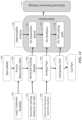
- FIG. 3is a block diagram showing some of the components typically incorporated in at least some of the clients, servers, and other devices on which the facility operates.
- FIG. 4is a network diagram showing an arrangement of computer systems on which the facility operates in some embodiments.
- FIG. 5is a data flow diagram showing data flows produced by the facility in some embodiments.
- FIG. 6is a flow diagram showing steps typically performed by the facility, in some embodiments, in order to manage a repository of observations for use in generating cutting models.
- step 601an action occurs with respect to the repository.
- FIG. 7is a table diagram showing example contents of an observation table used by the facility, in some embodiments, to store information about observations contained in the facility's observation repository.
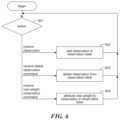
- FIG. 8is a flow diagram showing steps typically performed by the facility, in some embodiments, in order to generate a stream of machine commands and control signals for a cutting project.
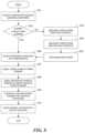
- FIG. 9is a flow diagram showing steps typically performed by the facility, in some embodiments, in order to generate a new cutting model.
- FIG. 10is a statistical graph diagram showing the derivation of curves from observations selected by the facility, in some embodiments, for each curve.
- FIG. 11is a table diagram showing sample contents of a cutting model table used by the facility in some embodiments to store cutting models generated by the facility for future reuse.
- FIG. 12is a flow diagram showing steps typically performed by the facility in some embodiments in order to take advantage of parallel processing resources.
- FIG. 13is a flow diagram showing steps typically performed by the facility in some embodiments in order to propose machine-operated parameters for project that are likely to improve on the result obtained.
- FIG. 14is a flow diagram showing steps typically performed by the facility in some embodiments in order to provide the advisory function.
- modelling of the expected workpiece geometryhas been a basis for more effectively generating tool machine commands control signals that allow a user to perform a cutting project.
- such modelingmay encompass determining the cutting speed that would allow the jet to separate the material or to generate a part according to specifications for the project.
- Conventional modeling techniquestypically use a predefined model, (such as one or more pre-set algorithms), of the beam's behavior or the result upon the workpiece, that is dependent on a fixed set of workpiece parameters: geometry, thickness, material type, and cutting results desired (one or more quality parameters, such as dimensional accuracy; absence or introduction of taper; surface finish, etc.).
- a unique static solution of motion control instructions specific to the active operating parameters that are being employed and workpiece machining objectivesis generated using the specific workpiece parameters that were all identified at the outset. If a workpiece parameter, such as its geometry or thickness, or an operating parameter, such as garnet flow rate, is subsequently changed, the modeling process starts again from the beginning in order to develop a unique solution for that specifically defined set of workpiece and/or operating parameters used to describe part created by the project.
- Conventional modelsoften make use of arbitrary “constants” or other correction factors, which can introduce subjective biases into the models.
- the inventorshave recognized that such conventional modeling techniques were typically narrow in focus (for example, modelling the effects of speed only), and might be for a limited and fixed set of parameters (such as material, pressure, etc.); and generally not well-disposed to rapid optimization.
- conventional modeling techniquesdo not perform a simultaneous review of differing possible operating parameters, but rather focus only upon the current active operating parameters.
- the models employedare not teachable to automate their improvement by the introduction of additional empirical data sets.
- the one-tool-path-at-a-time optimization methodrequires sequential compilations with vastly increased compiling times, and new operating parameters of the beam cutter technology must be changed either manually or within its own automated sequencing parameter ranges.
- a waterjet cutting toolmay perform waterjet cutting in a manner in which an abrasive substance is injected into the waterjet, and/or in a manner in which no abrasive substance is injected into the waterjet.
- the facilityis teachable, and encapsulates constantly adjusting and updated algorithms to model the cutting process and produce machine commands, as underlying cutting test data is added from an expanded group of potential sources.
- the facilityprocesses this tool path in order to generate a stream of machine commands usable to directly control a tool at a very fine level of resolution.
- the facilitystores some or all of the tool paths that it generates, and/or some or all of the machine command streams that it generates, in a data structure called a “project control data structure.” In some embodiments, this project control data structure further stores one or more cutting models used in generating tool paths stored in the project control data structure.
- facilitymay also be used to control a motion control system to perform other types of processing, including, in various embodiments, piercing, shaping, carving, milling, reaming, etching, and eroding.
- the facilityconstructs a statistical model, which is relied upon to generate a tool path.
- the facility's descriptive model of the resultant cut edge on the part formed by the beamuses results of cutting test made on a beam cutter, such as a waterjet machining system, typically with statistical confirmation to high certainty, permitting high confidence in the part program generated using the facility's model.
- the cutting tests and resulting observations used by the facility in model generationinclude measurements that provide information about the nature and performance of the cutting tool in connection with various processing operations, including such processing operations as cutting, piercing, shaping, carving, milling, reaming, etching, and eroding.
- the facilitymay automatically generate multiple possible models, which may, for example, suggest other possible operating parameters, for the user's consideration, such as to achieve fastest cutting, or (perhaps different) most economical cutting, or to meet other user objectives.
- the descriptive model constructed by the facilityis based only upon the operating parameters of the beam cutting technology employed (for abrasive-waterjet: pressure, fluid (such as water) flow rate, abrasive type, abrasive size, abrasive flow rate and others), and the material to be cut or otherwise machined.
- the models generated by the facilityare not dependent on any specific part geometry, material thickness, or selected operational parameters.
- empirical cutting datais used to determine, for each of a number of different aspects of the beam's effect on a workpiece is embedded within the modeling process, a function or other relation that predicts a value for the aspect—or “dependent variable”—based on the value(s) of one or more independent variables.
- these modeled aspectsinclude separation speed, jet lag, kerf width, taper error, surface finish, geometry, and position of the cutting front or other beam cutting effects such as maximum cutting depth.
- a descriptive mathematical function of the effect of the beam cutter, such as a waterjet machining system, on the workpieceis derived for separation speeds in regard to possible thicknesses and other jet parameters, as limited only by the implicit power of the beam cutter employed, given the possible operating parameters provided.
- determining one or more descriptive function(s), such as for the “separation speed”, then other descriptive functions, to describe other behaviors which are useful to the eventual workpiece tool path,can be derived, such as for the effect of jet lag, etc. All such first level functions can be derived independent of workpiece geometry, thickness, and possibly other operational parameters, which are not yet required.
- the facilityrelies on a cutting metric with respect to a particular material, thickness, and tool operating procedures called “separation speed.” This is, for a given cutting depth, the highest speed at which the jet can move and still completely penetrate the workpiece, such that the two sides of the workpiece are fully separated.
- the facilityrelies on a cutting metric with respect to a particular material, thickness, and tool operating procedures called “cutting depth at specified speed.” This is, for a given speed, the depth of material removed by the jet.
- the cutting processis forming a cut edge on either side of the cut, which will remain after completion of the process.
- the geometry of the remaining cut edgeis determined by the effect of the beam cutting process on the material at the cutting front. This cutting front constitutes the momentary effect of the process on the workpiece at the leading edge of the beam. Its geometric effect is constituted in the resultant cut edge of the workpiece, also referred to as the cut edge of the part or parts created by the processing project.
- Jetlagtypically the deviation of the cutting front from the jet vector in the cutting plane.
- the jetlagtypically varies with cutting depth
- Kerf widthtypically the width of the cutting kerf—the void created in the workpiece by the jet—at the top entrance of the jet into the material.
- the perfect kerfwould be formed by a parallel plane to the cutting plane with a distance of half of the kerf width (half the beam's diameter) to the cutting plane.
- Taper errortypically the deviation of the real cutting front from the perfect parallel kerf, perpendicular to the cutting plane.
- the taper errortypically varies with cutting depth.
- the facilitycollects and manages cutting test results, together with the material cut and cutting tool operating parameters used. These cutting test results and the associated information are referred to as “observations.”
- the facilityuses these observations as a basis for generating models that predict how the beam cutting machine, such as a waterjet machining tool, and its jet will affect the formation of a cutting front and thus the ultimate shape of the cut edge of a specific material. Those are, on one hand, dependent on such factors as material type and machine operating parameters, but on the other, independent of such factors as material thickness and an eventual objective workpiece geometric shape and possibly other selected parameters.
- This qualityallows such a model generated by the facility for a particular material type and particular operating parameters to be reused for any subsequent project using the same material type and the same or similar operating parameters, irrespective of differences in such factors as material thickness and geometric cutting shape and possibly other dependent operating parameters such as pressure, abrasive type and size, etc.
- the facilityto generate a model for a cutting project, the facility first selects from its full repository of observations those produced by cutting tests whose material type and operating parameters closely match those specified for the cutting project.
- the facilityenables development of one or more parametric functions based on existing observations and/or physical principles to the selected observations of the corresponding type, determining coefficients for the parametric function that causes it to best represent the behavior of the selectable observations.
- the modelling functions which are developed by the facilityare cutting speed as a function of material depth (given possible operating parameters for which the beam cutting tool employed is capable of achieving), jetlag as a function both of material depth and cutting speed, and taper as a function both of material depth and cutting speed.
- the facilitygenerates the modeling functions by determining coefficients in a manner based on additional factors beyond the selected observations.
- material type and/or operating parameterssuch as pressure, abrasive feedrate and others can be independent variables of the first level modelling functions.
- the first level functionsdescribe the effect of the jet on the workpiece for a straight line cut without tilting motion or direction change; or alternatively in another exemplary embodiment, including tilting motion or direction change.
- the facilityIn order to generate the second level functions, the facility then models the expected cutting front that generates the geometry of the cut edge for the whole range or a relevant part of non-constant conditions such as cutting depth, speed, direction, angle, parameter changes or other effects that change the expected cutting front and therefore the geometry of the cut edge such as corners, arcs, or bevels.
- the cutting modelcan still be independent of any specific or target workpiece geometry and could be applied to any cutting geometry with same or similar cutting parameters.
- the facilityreceives user input specifying the geometric characteristics of the specific anticipated workpiece, to reduce the possible outcomes calculated by the facility.
- the facilityreceives the geometry of a cutting project as a routed geometry, which consists of a possibly ordered list of cutting and traversing entities that contain but are not limited to information of the intended cutting geometries as value and changes of position, curvature, cutting depth, cutting angles, cutting quality etc.
- the cutting depthis included implicitly as workpiece thickness and cutting angle. From the specific geometry, specifications, and tool path of the cutting project, the facility uses the cutting model to derive speed profiles and tool path compensations.
- first- and/or second-level modeling functionsthat relate modeled dependent variables to corresponding independent variables
- the facilityconstructs relations of a variety of other types that it uses as a basis for predicting a value of the dependent variable based on a value of the independent variable.
- theseinclude probability distributions, lookup tables, fuzzy functions, etc.
- the facilitymanages the observations that it uses as a basis for generating cutting models, allowing a variety of actors to add, and in some cases rate, weight, and/or remove one or more observations in the repository of observations that it maintains and employs.
- the facilityassigns a rating and/or weight factors to a subject observation based on an analysis and comparison of that observation with pre-existing observations, experience data, physical laws, or other methods.
- the facilitybases the rating on an assertion of the expected quality of the subject observation from this specific source. In some embodiments, the facility applies this rating individually, or on the basis of a multi-user crowd rating system or other factors.
- the facilitypublishes and/or syndicates observations between different observation repositories, such as those associated with a central service and those associated with actors (for example “end users”) directly using the cutting machines.
- observation repositoriessuch as those associated with a central service and those associated with actors (for example “end users”) directly using the cutting machines.
- actorsfor example “end users”
- toolsWhatever financial arrangement permits such users of cutting machines to use the observations, and observation repositories (purchase, financed purchase, lease, loan, license, consignment, etc.) such users are referred to herein as “tool customers.”
- a particular tool customermay perform its own experimentation and (1) add the resulting observations to its own observation repository, and/or (2) add them to a central repository.
- the tool customermay be allowed to use the central observation repository in its entirety or a part thereof.
- This source tool customermay then generate models that gain the benefit of the expanding repository of observations, as may the operator of the central observation repository, and/or other tool customers that subscribe to the central observation repository.
- the tool customers who use particular observations to generate modelsmay be at an arbitrary distance from the geographic location where the cutting tests reflected in those observations were performed, and in some embodiments may not learn the identity of the actor performing the cutting tests and supplying the observations.
- the source of an observationis compensated for providing it to the central repository.
- observationsmay be provided by actors whose primary business lies with the performing cutting tests to generate observations and provide them for use by others, either via the central observation repository, or directly to the user or users.
- compensationis in a variety of forms, including government-issued currency, banking system credits, or proprietary credits.
- model construction and/or control signal generationis performed as a service by a central service provider, including a provider that operates in a cloud.
- users of this servicepay a marginal fee for its use.
- the serviceis free for tool customers who are authorized users of a tool provided by a particular tool manufacturer.
- the serviceis capable of providing modeling and/or control signal generation services at differing levels of efficacy (including resource efficiency, and/or result quality), and establishes differential pricing for such services.
- a manufacturerprovides a tool to a tool customer at a certain price with a limited set of cutting models, and/or a limited version of the facility for generating cutting models, and charges the tool customer more to use the facility, and/or use less-limited models generated by the facility.
- the tool customerpays based on the number and size of cutting projects performed, the number and/or quality of models used, amount of abrasive consumed, a fixed periodic amount for tiered or unlimited service, etc.
- the provider of the facilitycharges a tool customer for maintenance of and/or updates to the observation repository.
- the tool customerpays based on the number of cutting projects performed, the number and/or quality of models used, amount of abrasive consumed, a fixed periodic amount for tiered or unlimited service, etc.
- the facilitydecomposes control signal generation for a project into portions called “streaks” that each begin with a “beam on” command, contain one or more cutting entities (cutting lines and/or cutting arcs, for example), and end with a “beam off” command, and distributes these streaks to different processing entities for parallel processing.
- the facilitysuggests variations in tool operating parameters likely to achieve the end user's particular objectives such as for part accuracy, part production time, part cost, equipment usage, and other end user objectives.
- the facilitymay incorporate weighting of such objectives, which may otherwise compete.
- such variationscan include altering focus tube diameters, orifice sizes, garnet types, grades and flow rates, pressures, etc.
- the facilitytests the variation of varying orifice size by determining the effect of this variation on the model's descriptive functions and, consequently, its effect on estimated cutting accuracy and speed.
- the alternative descriptive functional setsare simultaneously retained into memory to compare for the optimum operating parameters, given the later introduction of specific workpiece parameters, including cutting objectives such as the quality requirements.
- a single instance of the facilitycan be used with respect to tools of a variety of models, and/or with respect to tools from a variety of manufactures.
- the facilityBy operating in some or all of these ways, the facility generates tool paths and machine commands at high levels of automation, resource efficiency, result quality and/or other tool customer objectives.
- tool pathscan be compiled quickly with relatively small amounts of computing resources because of the focus on functional relationships to describe the resultant cut edge; (2) the modeling process for any material is easily improvable, even by the user/operator, by the submission of new observations; (3) if the user is cutting only one material over and over again, to different geometries and/or thicknesses, the initial levels of functional modeling for that material are already done and may be repeatedly reused; and (4) where a customer uses a modeling and/or control signal generation service, it is relieved of the processing burden of itself conducting this work.
- FIG. 1is a perspective view illustrating one type of beam cutter tool, a waterjet machining system 100 , configured for use with the facility in some embodiments.
- the system 100can include a beam generating source 102 (shown schematically) (e.g., a fluid-pressurizing device, a laser source, or a plasma source) configured to generate a beam for processing through a beam inlet (not shown), with or without being subjected to a conditioning unit (not shown), and with or without being stored in a reservoir (not shown).
- the systemfurther includes a cutting head assembly 104 operably connected to the beam generating device 102 via a conduit 106 extending between the beam generating device 102 and the cutting head assembly 104 .
- the system 100can further include a base 114 , a user interface 116 supported by the base 114 , and a second actuator 118 configured to move the waterjet assembly 104 relative to the base 114 and other stationary components of the system 100 (e.g., the fluid-pressurizing device, a laser source, or a plasma source 102 ), or to move the base 114 relative to the cutting head assembly, (such as a stationary waterjet assembly) 104 , or to move both.
- the second actuator 118can be configured to move the cutting head assembly 104 along a processing path (e.g., cutting path) in two or three dimensions and to tilt cutting head assembly 104 relative to the base 114 , or to tilt the base relative to the cutting head assembly 104 , or to tilt both.
- the second actuatortilts the cutting head assembly 104 in each of two dimensions: a tilt-forward within the cutting plane that is perpendicular to the top surface of the work piece and contains the motion vector, and a lateral tilt rotation within a plane that is perpendicular both to the cutting plane and to the top surface of the workpiece.
- the conduit 106includes a joint 119 (e.g., a swivel joint or another suitable joint having two or more degrees of freedom) configured to facilitate movement of the cutting head assembly 104 relative to the base 114 .
- the cutting head assembly 104can be configured to direct a beam toward a workpiece (not shown) supported by the base 114 (e.g., held in a jig supported by the base 114 ) and to move relative to either the cutting head assembly 104 or the base 114 , or both, while directing the jet toward the workpiece.
- the systemcan also be configured to manipulate the workpiece in translatorical and/or rotatorical motion or a combination of both, manipulating the jet and the workpiece.
- the user interface 116can be configured to receive input from a user and to send data based on the input to a controller ( 124 ).
- the inputcan include, for example, one or more specifications (e.g., coordinates, geometry or dimensions) of the processing path and/or one or more specifications (e.g., material type or thickness) of the workpiece and operating parameters (e.g., for a waterjet tool, pressure, flow rate, abrasive federate; for a plasma tool, electric current; for a laser tool, beam intensity).
- the cutting head assembly 104can include a beam outlet 108 and a control device 110 upstream from the beam outlet 108 .
- the control device 110can be configured to receive fluid from the fluid-pressurizing device 102 via the conduit 106 at a pressure suitable for waterjet processing or gases and electric current for plasma cutting or a laser beam for laser cutting.
- the control devicecan be positioned at a different location between beam generating device 102 and the cutting head assembly 104 .
- the system 100can further include a consumable delivery apparatus 120 configured to feed consumables, such as particulate abrasive or process gases, from a consumables storage container 121 to the cutting head assembly 104 or to the beam generating device 102 .
- consumablessuch as particulate abrasive or process gases
- the processing beamis generated that in some embodiments can consist of a laser beam possibly surrounded by process gasses, a fluid jet with or without added and accelerated abrasive particles or a gas jet that is transformed into a plasma beam by applying electric current.
- the consumable delivery apparatus 120is configured to move with the cutting head 104 relative to the base 114 , or vice versa.
- the consumable-delivery apparatus 120can be configured to be stationary while the cutting head assembly 104 moves relative to the base 114 .
- the controllercan be configured to vary the demanded power at the beam device or within the system.
- the systemcan consist of one or more cutting heads that can be controlled individually and can be applying same or different parameters (orifice size, mixing tube size, abrasive size, abrasive type, abrasive feedrate, etc.).
- the base 114can include a diffusing tray 122 , such as, among others, one configured to hold a pool of fluid positioned relative to the jig so as to diffuse the remaining energy of the jet from the cutting head assembly 104 after the beam passes through the workpiece.
- the system 100can also include a controller 124 (shown schematically) operably connected to the user interface 116 , the first actuator 112 , and the second actuator 118 , in a variety of fashions or steps of hardware.
- the controller 124is also operably connected to a consumable metering device 126 (shown schematically) of the consumable delivery apparatus 120 .
- the consumable delivery apparatus 120can be without the metering device 126 or the metering device 126 can be configured for use without being operably associated with the controller 124 .
- the metered consumablescan be but are not limited to process gases, electric power, or abrasive garnet.
- the controller 124can include a processor 128 and memory 130 and can be programmed with instructions (e.g., non-transitory instructions contained on a computer-readable medium) that, when executed, control operation of the system 100 .
- instructionse.g., non-transitory instructions contained on a computer-readable medium
- the systemcan be configured to contain one or more independent or connected motion control units.
- the systemcan be configured in various ways that allow perpendicular, rotational and/or angular cutting of workpieces of different shape.
- Embodiments of the systemcan include but are not limited to gantry, bridge, multi-axis kinematics (similar in function to OMAX Tilt-A-Jet or A-Jet tools), 6-axis robot, rotary, and hexapod style machines.
- the systemis suited to cutting workpieces of a wide variety of thicknesses, including workpieces of negligible thicknesses.
- the system 100uses various fluids other than water and can also include gases.
- the system 100is adapted to cut workpieces of a variety of three-dimensional shapes.
- the jetcan cut at any angle relative to the workpiece.
- the facilityWhile some embodiments of the facility are adapted for use in connection with the beam cutters, such as a waterjet system 100 , in some embodiments the facility can be used with any motion system, including robots, hexapod, and other tilting mechanisms.
- FIGS. 2 A- 2 Eare processing diagrams that illustrate the effect of the beam tool, such as a waterjet cutting tool, on the shape of the resulting cutting front and the use of tilting to compensate for them.
- the cutting frontrepresents the effect of the beam tool on the workpiece at the leading edge of the beam.
- FIGS. 2 A- 2 Billustrate compensation for the effect of jetlag on the cutting front.
- FIG. 2 Ais a side view processing diagram illustrating the cutting front due to jetlag without tilt-forward compensation.
- the direction of motion of the cutting headis toward the right side of the diagram.
- the jet 202is projected along a jet vector 201 that is perpendicular to the top surface of the workpiece 203 . Due to the motion of the cutting head toward the right side of the diagram, the cutting front shape 202 extends toward the left side of the diagram, away from the jet vector. Accordingly, while it would be ideal to have removed all of the material from the workpiece in the cutting path except rectangular section 204 , the jet has also failed to remove roughly triangular section 205 .
- FIG. 2 Bis a side view processing diagram illustrating the cutting front tool shape behavior with tilt-forward compensation.
- the tilt-forward feature of the shown waterjet systemis used to rotate the jet access 211 toward the direction of travel of the cutting head.
- the leading edge of the cutting front 212is nearly vertical, leaving very little excess material other than rectangular section 214 .
- FIGS. 2 C- 2 Eillustrate the effect of the beam tool on the sides of the cutting front, which is inducing taper and its compensation method, for a straight or arced cut perpendicular into the drawing's plane.
- FIG. 2 Cis a front view processing diagram illustrating the cut edge behavior without lateral shift or lateral tilt compensation.
- the direction of motion of the cutting headis perpendicular to the plane of the diagram.
- the jet 222is projected along a jet vector 221 that is contained by the plane to be cut at the edge of the workpiece 223 , which is the left edge of trapezoidal region 225 .
- all of the workpiece material that is within the cross-section of the jet 222is removed, including trapezoidal region 225 , which is intended to remain intact as a portion of the cut part.
- FIG. 2 Dis a front view processing diagram illustrating the cut edge behavior with lateral shift compensation, as indicated by the kerf width of the cut edge. It can be seen by comparing FIG. 2 D to FIG. 2 C that the jet vector 231 has been shifted laterally, away from the part being cut, by an offset distance 237 relative to jet vector 221 shown in FIG. 2 C .
- This offset distance 237is half of the kerf width—the width of the channel circle cut into the top surface of the workpiece 223 by the jet.
- the triangular region 235 errantly removed in FIG. 2 D after this lateral shiftis smaller than the trapezoidal region 225 errantly removed in FIG. 2 C without the lateral shift.
- FIG. 2 Eis a front view processing diagram illustrating the cut edge behavior with lateral shift and lateral tilt compensation as indicated by the taper of the cut edge. It can be seen by comparing FIG. 2 E to FIG. 2 D that the jet vector 241 has been rotated in plane perpendicular to the cutting head's direction of travel, away from the part being cut, by an angle alpha 246 relative to jet vector 231 shown in FIG. 2 D . This angle alpha is derived from the modelled geometry of the remaining workpiece to generate the demanded shape of the edge of the workpiece. In FIG. 2 D it is established to be at least approximately equal to the angle at the top of triangular region 235 .
- the facilityapplies cutting optimization criteria to determine the optimal tilt compensation.
- cutting optimization criteriainclude but are not limited to: minimal maximum deviation, minimal average deviation, or minimal deviation at specific cutting depths.
- the facilitygenerates its cutting models from variable pools of cutting test observations; the cutting models derived automatically update, as the input observations are modified, including insertions and deletions.
- the facilityuses a pool of observations that was pre-populated by one entity like the manufacturer of the machine, but is also open to accepting additional observations from other sources to provide a basis for constructing better models.
- the additional data sourcescan be customers/service providers that need to cut a very specific material that has not been included in the original pool of observations, since it may be of limited value to other customers. It can include additional testing that a customer wants to perform to increase the precision of the cutting model in an area that is very sensitive for the customer.
- the generation of this data tablecan be performed by this customer, it can be performed as a service by the manufacturer, or by a third party, including groups operating in a cloud environment—and as distributed data sets.
- the facilityalso allows the manufacturer to provide data sets for specific configurations or materials to a customer as an optional product at additional cost.
- the extent of cutting modelcould be very limited and the customer can e.g. later obtain, for example, a “Ceramic Cutting Model Package,” or can obtain a package for a specific parameter (e.g. nozzle) combination.
- the facilityalso enables third parties to offer data sets as a service.
- a companymay generate a comprehensive data set for a special material.
- the facilityenables the company to sell the use of this dataset to other companies by providing an environment similar to an internet marketplace, or via other channels.
- the likelihoodincreases of being able to select observations as the basis for a model that closely mirrors the characteristics of the projects for which the model will be used. This, in turn, enables the facility to rely to a lesser degree on observations that more significantly diverge from the characteristics of the projects for which the model will be used.
- the facilitystores additional information about each observation that relates the observation to the tool on which the cutting test that produced the observation was performed, such as an identifier of the tool, and/or detailed characteristics of the tool (i.e., the nature of the tool, its operating parameters, etc.) that may have affected the results of the cutting tests.
- the facilitycreates a model tailored to a particular tool expected to be used for an associated project or projects (the “target tool”), which has its own detailed characteristics. In such cases, the facility selects observations for incorporation into the model based in part about how well the information about detailed characteristics of the tools that were the source of the observations matches the information about detailed characteristics of the target tool.
- the facilitywhile the model generated for a particular project is itself not customized for the detailed characteristics of the target tool, the facility generates additional machine commands or tool settings for transforming information produced by the general model into information tailored for the detailed characteristics of the target tool.
- the facilityuses its tracking of detailed tool characteristics as described above as a basis for generating models and compiling tool paths across tools that differ to varying degrees, including in some cases tools of the same model that are configured differently; different tool products from the same manufacturer; tools from different manufacturers; etc. That is, in such embodiments, tools that differ in these ways from a target tool may nonetheless be used to perform cutting tests that produce observations that are included in the observation repository used to generate a model for the target tool.
- Different sources of cutting test resultsmay have varying reliability or trustworthiness.
- a usermay trust his or her own cutting data more than the data from the manufacturer or from a third party.
- the facilityuses a weighting factor (e.g., one based on reliability), when merging data from different sources. That means, for example, the data from reliable sources may be preferred over data from less reliable sources if both data sets are available for the given condition. In some embodiments, if only one data set is available at this condition (e.g., for an uncommon material), the facility may use this data set because it is more reliable than extrapolating data from very different conditions.
- the reliability index for each datasetcan be assigned by the user who is using distributed data sets, including changes to the reliability index assigned, based upon later experience or other factors.
- the facilityderives the weighting factor from a rating system that incorporates experiences from different users, and therefore can change over time.
- the reliability indexis assigned by data provider or even differently per data provider.
- a part of the weighting factoris generated by self-assessment of the data provider.
- the facilitymaintains two or more different kinds of weighting factors for each observation.
- thesecan include one that the source of the observation applies, e.g., for the trustworthiness of the operator that performed the test; one that an operation of an observation service applies to quantify the trustworthiness of the source; and/or one that is based on a rating system by users of the data, similar to rating of vendors and/or products at consumer product retailing websites.
- the facilityautomatically rates the cutting test observations uploaded based on comparing with previous cutting test observations, and/or facilitates human review and rating, such as to prevent spamming or mistakes among the cutting test observations from corrupting models that would otherwise be based on them.
- the facilityassesses cutting test observations previously uploaded by the same user or company to establish trust. The facility then automatically assigns newly-uploaded cutting test observations a trust/reliability attribute based on the past rating for the entity providing the data.
- each cutting test observationhas an identifier identifying the entity that submitted it, so that, should future data turn out to be malicious, past data from that submitting entity can be removed or reduced in trust accordingly.
- the facilitytreats an encapsulated copy of a cutting model similarly.
- the facilitygenerates the functional model from the test data and physical and empirical constraints. Instead of sharing the test data, in some embodiments the facility shares the abstract model in some or all of the ways described in the paragraph above.
- the facilityencapsulates the cutting model and causes it to be provided to the computer to perform the compilation.
- FIG. 3is a block diagram showing some of the components typically incorporated in at least some of the clients, servers, and other devices on which the facility operates.
- these devices 300can include server computer systems, desktop computer systems, laptop computer systems, netbooks, mobile phones, personal digital assistants, televisions, cameras, automobile computers, electronic media players, computer cards, etc.
- the computer systems and devicesinclude zero or more of each of the following: a central processing unit (“CPU”) 301 for executing computer programs; a computer memory 302 for storing programs and data while they are being used, including the facility and associated data, an operating system including a kernel, and device drivers; a persistent storage device 303 , such as a hard drive or flash drive for persistently storing programs and data; a computer-readable media drive 304 , such as a floppy, CD-ROM, or DVD drive, for reading programs and data stored on a computer-readable medium; and a network connection 305 for connecting the computer system to other computer systems to send and/or receive data, such as via the Internet or another network and its networking hardware, such as switches, routers, repeaters, electrical cables and optical fibers, light emitters and receivers, radio transmitters and receivers, and the like. While computer systems configured as described above are typically used to support the operation of the facility, those skilled in the art will appreciate that the facility may be implemented using devices of various types and configurations, and
- FIG. 4is a network diagram showing an arrangement of computer systems on which the facility operates in some embodiments.
- the diagramshows a tool customer computer system 410 that is operated by, and in some cases owned, by the tool customer that operates a beam cutter, such as the example waterjet machining system 430 .
- the tool customer computer systemis located on the same premises as the tool.
- Executing on the tool customer computer systemis the facility 411 for collecting cutting test observations 412 , using them to construct cutting models 413 , and applying those cutting models to determine, for each cutting project, a tool path, and corresponding tool commands 420 .
- the tool customer computer systempasses the tool commands, via various possible configurations of hardware and/or software, to the tool for execution to perform the cutting project.
- various portions of the functionalityare completely offloaded to or assisted by a modeling and compilation service computer system 450 via the Internet 440 .
- the modeling and compilation service computer systemis operated by the manufacturer of the tool.
- the observations 412 used by the facility on the tool customer computer system to generate cutting models 413are managed by the modeling and compilation service computer system and published to the tool customer computer systems of one to multiple tool customers. In some such cases, observations managed by the modeling and compilation service computer system are contributed by a variety of different tool customers, and/or other third parties.
- the observations used by the facility on the tool customer computer system to construct a particular cutting modelare selected for the project and returned by the modeling and compilation service computer system.
- the modeling and compilation service computer systemitself constructs and/or caches models needed by the tool customer computer systems, and/or tool paths and/or machine commands that are based on such models.
- FIG. 5is a data flow diagram showing data flows produced by the facility in some embodiments.
- the diagramshows observations 501 . These contain the results of cutting tests performed with a beam cutting tool, such as the exemplary waterjet cutting machines. In some embodiments, the observations reflect the results of cutting tests to determine (for example): separation speed, jetlag, kerf width, and taper. Each of the cutting tests is performed based upon material of a particular type, and a number of machine operating parameter values, such as, for the example, orifice diameter, mixing tube diameter and length, pressure, abrasive type and feed rate, material type, class and thickness, cutting head design, etc.
- a separation speed cutting testmeasures the separation speed under those particular conditions.
- a separation speed cutting testis in some embodiments performed by conducting a number of different cuts in the workpiece at different speeds, and identifying, among the cuts achieving full separation, the one performed at the highest speed.
- a single separation speed cutting test with a single workpiecetypically produces a single separation speed.
- the recorded observationsalso may include the results of piercing tests, etching tests, milling tests or still others.
- a jetlag cutting testmeasures jetlag.
- a jetlag cutting testis in some embodiments performed by making cuts in a workpiece at different speeds; in each cut, the jet is switched off abruptly while the cutting head continues to move.
- the jetlagis determined by measuring the distance at one or more cutting depth.
- Another approachis to analyze the patterns at cut edge surface or derive the jetlag from measuring the geometry of an arced cut.
- various other approachesare used to perform a jetlag cutting test.
- a kerf width cutting testmeasures the kerf width at the entry point of the cut for a given cutting speed.
- a taper cutting testmeasures taper error. Taper is defined as deviation from the top measured kerf width.
- a taper cutting testis in some embodiments performed by making straight or arced cuts in a workpiece at different speeds. In each cut, the taper distance is measured at each of one or more depths by determining the distance perpendicular to the direction of travel from the extent of the cut on the top surface of the workpiece to the extent of the cut at the depth being measured. Thus, a single taper cutting test can produce a number of different taper errors, each corresponding to a different combination of speed and depth.
- the facilityreceives, adds to its observation repository, and incorporates into models cutting tests that vary in certain respects, such as cutting tests that involve cutting in shapes other than straight lines, and/or cutting tests that involve cutting at tilt-forward and/or lateral tilt angles other than vertical.
- the number of cutting tests of each of the different typesis performed with different materials and various values of different machine operating parameters. In some embodiments, all of the cutting tests are performed by the manufacturer of the tool. In some embodiments, the cutting tests are performed by a variety of parties in possession of tools, including the manufacturer, customers, other third parties, etc. In some embodiments, the observations 501 can be collected over time, as is discussed in greater detail below in connection with FIG. 6 .
- the facilitydetermines whether a cutting model appropriate for the project already exists based upon the material type and machine operating parameters specified for the project. If such a cutting model does not already exist, the facility constructs an appropriate model, as is discussed in greater detail below in connection with FIG. 9 .
- the facilityfurther generates a general model of different possible geometries 520 , that specifies the cut edge of the specific geometric element, (corners, radii, angles), up to the maximum thickness possible for the material specified and for the given or possible operating parameters.
- the outcomes calculated for the possible library of changes in geometric elements' shape and thicknessmay be reduced by providing the actual geometric shape and thickness of the target workpiece.
- the facilityobtains for the target workpiece the routed geometry that contains the specific geometric elements 511 , cutting depth and quality specifications 521 to generate/assemble a tool path 530 specifying a speed at which the cutting head is to travel during each segment of the routed geometry.
- the quality specificationspecifies, for each segment of the routed geometry, a level of quality to be imposed on the cut edge: that is, for example, the degree of roughness of the cut edge; edge taper desired; etc.
- the facilityuses this information in order to generate a tool path, as is discussed in greater detail below.
- the generated tool pathincludes compensation for the radius of the jet, such as by incorporating an offset equal to the jet radius in the kerf width measure used in the tool path.
- the facilityapplies a mechanical model 531 specifying the operational limits of the tool to obtain a machine-limited tool path 540 that specifies speeds for each segment of the geometry that are within the capabilities of the tool. Some of the operational limits include maximum machine speed, maximum machine acceleration, permissible machine limits for each axis, etc.
- the facilitythen transforms the machine-limited tool path into machine commands 550 suitable for execution by the tool in order to perform the project.
- FIG. 6is a flow diagram showing steps typically performed by the facility in order to update and organize an evolving repository of observations for use in generating cutting models.
- an actionoccurs with respect to the repository. If the action is to receive a new observation, then the facility continues in step 602 to add the observation to an observation table that embodies the observation repository in some embodiments. Additional details about the observation table are discussed in connection with FIG. 7 below.
- the facilitycontinues in step 601 to process the next action with respect to the repository. If the action is to receive a command to delete a particular observation from the repository, then the facility continues in step 603 to delete the specified observation from the observation table. After step 603 , the facility continues in step 601 to process the next action with respect to the repository.
- the facilitycontinues in step 604 to change a weight associated with the observation in the observation table that specifies the degree to which the observation to be incorporated into cutting models for which it is otherwise appropriate.
- the facilitysupports a variety of other actions for organizing and editing its observations repository.
- the facilitypermits a user to designate observations that will be available for use in generating a model.
- the facilitypermits such a user to control which observations are included in versus excluded from the observation repository.
- the facilitypermits such a user to set a flag or other indication maintained in the observation repository for each observation that specifies whether the observation will be available for use in generating models and on the basis of any designated weight or bias.
- FIG. 7is a table diagram showing example contents of an observation table used by the facility in some embodiments to store information about observations contained in the facility's observation repository.
- the observation table 700is made up of rows, such as rows 701 - 714 , each corresponding to a single observation contained by the observation repository.
- Each rowis divided into the following columns: an ID column 721 containing an identifier that can be used to refer to the observation, such as a unique identifier; a timestamp column 722 containing an indication of the time at which the observation was most recently added to or updated in the observation table; a source column 723 identifying the provider of the observation, such as the entity who performed the cutting test that yielded the observation, or an intermediary through which the information was obtained; a material or material type column 724 naming the material that was the subject of the cutting test; a material index column 725 containing a material index indicating the relative susceptibility of the material to beam tool cutting, such as cutting by a waterjet machining system; a group of operating parameters columns 726 (contents not shown for brevity) that identifies values for tool operating parameters used in the cutting test (such as pressure, abrasive flowrate, radius of cut, etc.); a test type column 727 indicating which type of cutting test was performed; a depth parameter column 728 indicating,
- row 703indicates that the observation having identifier 46798 was last added or updated on Jan. 11, 2015 at 6:22:01 PM; was received from customer A; involved cutting the material polycarbonate having a material index of 517; was performed using a tool having a variety of operating parameter values not shown for brevity; was a measurement obtained from a jetlag cutting test at a depth of 2.0 mm and a speed of 2.0 mm/s; and yielded a jetlag measurement of 0.41 mm.
- observation tablewill contain observations for a wide variety of materials having different material indices.
- the observation tablealso includes a material class such as metal, stone, or plastic used to characterize together groups of materials with similar cutting properties.
- the observation tablealso includes further details about the material that was the subject of the cutting test, such as (a) a particular alloy or other recipe or method used in making the material, and/or (b) manufacturing or treatment techniques used in the production of the material and/or (c) specific properties of the material such as for example hardness or yield strength.
- the facilitywhen constructing a model for a particular material, uses various combinations of this information about the material that was the subject of the cutting tests corresponding to the observations in the observation table to determine their level of similarity to the modeled materials as a basis for selecting observations for use in constructing the model.
- the diagramalso shows a last update time field 740 for the entire table, showing the last time at which any contents of the table were changed, such as by adding, changing, or deleting a row.
- a last update time field 740for the entire table, showing the last time at which any contents of the table were changed, such as by adding, changing, or deleting a row.
- the facilitynonetheless creates a new cutting model if the existing cutting model was created prior to the last update time for the observation table, to ensure that new and changed observations are reflected in any cutting model used.
- the creation of a new cutting model in such circumstancesis at the discretion and option of the operator.
- FIG. 7 and each of the table diagrams discussed belowshow a table whose contents and organization are designed to make them more comprehensible by a human reader
- actual data structures used by the facility to store this informationmay differ from the table shown, in that they, for example, may be organized in a different manner; may contain more or less information than shown; may be compressed and/or encrypted; may be distributed across several tables or data structures of other types, etc.
- FIG. 8is a flow diagram showing steps typically performed by the facility in some embodiments in order to generate a stream of machine commands and control signals for a cutting project.
- the facilityreceives material and machine operating parameters for the project.
- step 802if a suitable cutting model is available for use in the project—that is, a model exists that was generated for material and machine operating parameters that are similar enough to those received in step 801 —then the facility continues in step 806 to use an existing cutting model, else the facility continues in step 803 to generate the first level modeling functions for a new cutting model for the project.
- the first level functionscan describe the geometric properties, as outcomes from the machining operation on the workpiece (e.g., separation speed, jet lag, taper, kerf width), as resultant aspects.
- the facilityuses observation tables, either in their entirety or parts thereof, a separate observation table, or another mechanism, to verify the validity of the first level functions and/or to adjust the first level functions accordingly. Additional details about step 803 are discussed below in connection with FIGS. 9 and 10 .
- the second level function in step 804describe the expected geometrical shape of the cutting front and the resulting cut edge at any of a multiplicity of geometrically different cutting entities.
- the relevant parameters for the second level functioncan include but are not limited to curvature, direction, tilting angle as well as changes in those geometrical properties along the cutting entities. In some embodiments the full possible extent of relevant geometrical parameters is included in those second level functions. In other embodiments a subset of reasonable ranges based on the specifications of the current cutting project or other criteria can be selected. Additional details about step 804 are discussed below in connection with FIGS. 9 and 10 .
- step 805the facility stores the generated cutting model in a cutting model repository embodied by the cutting model table. Additional details about step 805 are discussed below in connection with FIG. 11 .
- step 806the specific geometry of the cutting project and its specifications are received.
- step 807the facility applies the cutting model generated in step 804 or the existing suitable cutting model identified in step 803 to the actual geometry and specification of the routed geometry for the cutting project in order to obtain a tool path. Additional details about that 807 are discussed below in FIG. 9 .
- step 808the facility applies a mechanical model specifying the mechanical limits of the tool to the tool path obtained in step 807 to obtain a machine-limited tool path. In some embodiments, the facility generates this machine-limited tool path in an earlier step.
- step 809the facility transforms the machine-limited tool path into machine commands executable by the tool.
- step 810the facility sends the machine commands to the tool for execution. After step 810 , these steps conclude.
- FIG. 9is a flow diagram showing steps typically performed by the facility in order to generate a new cutting model.
- the facilityloops through each dependent variable modeled by the facility, also called a “modeled aspect” of the beam tool's effect on the workpiece. In some embodiments, these include, for example, separation speed, jetlag, kerf width, and taper.
- the facilityidentifies observations in the observation table that are suitable for the model. In some embodiments, this involves selecting observations for tests of the corresponding test type. In some embodiments, this involves selecting observations from tests performed using a material that is either the same as or similar to the material specified for the model, and/or a material having a similar material index. In some embodiments, this involves selecting observations from tests performed using the same or similar values of tool operating parameters as those specified for the model.
- the facilitydetermines second level functional relationships of other modeled aspects for a library of possible radii, speeds, and cornering strategies, either stored as new second level derivative functions, or alternatively as look up tables/matrices of the resulting calculations.
- the facilityuses the utilized observation table in its entirety or a part thereof, a separate observation table, or another mechanism to verify the validity of the second level functions and/or to adjust the second level functions accordingly.
- the usercan develop a tool path for any geometry and any thickness and any other independent variable, for the material selected and the waterjet equipment operating parameters being employed.
- step 903the facility models a function of predetermined form to the observations identified in step 902 .
- the facilityhas modeled function 1014 to the selected separation speed observations for the aspect of separation speed.
- the facilityperforms this modeling starting with a parametric equation determined by the inventors to generally represent the relationship between the modeled quantities over a wide range of values.
- FIG. 10is a statistical graph diagram showing the modeling of predetermined parametric functions for modeled dependent variables (“modeled aspects” or “aspects”) to observations selected by the facility for each dependent variable.
- graph 1010corresponding to the speed function, in which the X axis 1011 is depth and the Y axis 1012 is separation speed, shows points corresponding to the observations selected for the separation speed function by the facility as points, such as point 1013 .
- the facilityproceeds in step 904 to determine values for the coefficients a, b, c, and d that cause the resulting function of the independent variables x and z, which could be cutting depth, cutting speed or others to most accurately represent the selected observations using least square of error, minimum deviation or other measures.
- the coefficients selected by the facilityresult in function 1014 .
- This curverepresented by the speed equation with the determined coefficients included, can be used to reliably predict, for a wide range of depths, including those for which no experimental data is available or for which the available experimental data is somewhat aberrant, what the cutting performance—and therefore the separation speed—will be for the material and operating parameters specified for the project.
- step 905if additional functions remain to be processed, then the facility continues in step 901 to process the next function, else these steps conclude.
- Graphs 1020 and 1030 in FIG. 10show derivation of functions for the jetlag and taper functions, respectively.
- graph 1020shows that the facility actually fits a different jetlag function for each of multiple cutting speeds, speeds 1-3. As shown here, speed 1 is the highest speed, speed 2 is the second high-speed, and speed 3 is the third highest speed.
- graph 1030shows that the facility fits a different taper function to each of multiple cutting speeds, speeds 1-4. Again, here, speed 1 is the highest speed, but one skilled in the art will understand that the scale highest to lowest can be reversed or otherwise altered.
- the modeling functionsare dependent on one or more of cutting depth, cutting speed, and tool operating parameters like pressure, abrasive feedrate, or others. In some embodiments, the selection of the modeling function is based at least in part on preexisting know-how.
- a functional model constructed by the facilitycan be represented simply by the coefficients selected by the facility for the modeling function for each aspect. Such a model can be quickly and inexpensively transmitted and stored. Such a functional model can also be efficiently evaluated for any geometry or material thickness. Further, such a functional model tends to be stable; that is, it tends not to experience any significant discontinuities.
- FIG. 11is a table diagram showing sample contents of a cutting model table used by the facility in some embodiments to store cutting models generated by the facility for future reuse.
- the cutting model table 1100is made up of rows, such as rows 1101 - 1112 , each corresponding to a single one of the three functions making up a cutting model stored in the facility's cutting model repository.
- Each rowis divided into the following columns: a model identifier column 1121 identifying the cutting model to which the row corresponds; a timestamp column 1122 containing an indication of the time at which the model was added to cutting model table; a material type column 1123 naming the material that was the subject of the cutting test; a material index column 1124 containing a material index indicating the relative susceptibility of the material to cutting, such as cutting by a waterjet tool; a group of operating parameters columns 1125 (contents not shown for brevity) that identifies values for tool operating parameters for which the model was created; a function column 1126 indicating which function of the model the row represents; a speed parameter column 1127 indicating, for jetlag and taper functions, the cutting speed parameter value to whose function the row corresponds; and coefficients columns 1128 - 1131 containing the coefficients determined by the facility to define the function.
- data from the utilized observation tablein its entirety or a part thereof, a separate observation table, or another mechanism to verify the validity of
- the cutting pathconsists of a sequence of segments, each of which can have constant or varying geometrical properties (e.g., angle, direction, cutting depth, and curvature) along its extent, which can range from magnitudes of single motor steps to long rule based entities.
- the facilitydetermines a maximum cutting speed that satisfies the segment's specific constraints regarding surface finish, tolerances, etc.
- the facilityuses the descriptive first and second level modeling functions (jetlag, taper, separation speed, etc.) and the geometry of the cutting path (curvature, cutting angles, cutting depth, etc.) for the modeled aspects to determine the expected cut edge geometry and optimize the operating parameters using geometrical mathematical approaches (known from calculus, vector algebra etc.) so that the specific requirements are met.
- the facilityconsiders the second derivative. If this is positive at this extreme point, it would be a minimum; negative would indicate a maximum. The minimum value of x at this condition is zero, and the maximum value of x is maximum possible or the actual cutting depth. If the absolute maximum is not within the actual cutting depth, the facility determines whether the local maximum occurs at the boundary conditions (zero cutting depth or maximum cutting depth).
- the facilitycan perform the optimization by varying the cutting speed alone, or by also modifying the tilting angles relative to the nominal jet vector.
- the facilityderives both of the tilting angles from the cutting model functions and/or the functional description of the expected non-tilting cut edge geometry.
- the facilityoptimizes operating parameters until the required constraints (tolerances, surface finish, etc.) are met, and also including other possible identified constraints, such as part production time, part cost, equipment utilization, etc.
- the facilityconstructs and applies models that vary in a variety of ways from those described above, including, in some cases: (a) those that vary in the degree to which they are targeted at a particular material type; (b) the degree to which they are targeted to particular tool operation parameters; (c) the degree to which they are targeted to particular physical configurations of the tool, such as particular nozzles, cutting heads, etc.; (d) the degree to which they are targeted to particular processing applications, such as, for waterjet cutting, waterjet piercing, waterjet etching, or other machining processes that can be performed by a waterjet machining system; and (e) the degree to which they are targeted to other economic or non-economic objectives, such as part cost and/or equipment utilization and/or beam tool maintenance objectives.
- the cutting model repositorycontains information about at least some of the projects each stored model was used on; in some embodiments, the cutting model repository is stored within a project control data structure.
- FIG. 12is a flow diagram showing steps typically performed by the facility in some embodiments in order to take advantage of parallel processing resources.
- the facilitycan divide the routed geometry for this project into two or more “streaks”. Those each contain a sensible portion of the routed geometry. Sensible streaks can contain portions of similar length. Typically the division between streaks occurs at a point where the tool is traversing and therefore the jet, for example in abrasive waterjet cutting, is turned off. The smallest typical ‘streak’ would therefore begin with a tool-on command; end with a tool-off command and machining/cutting operations in between.
- streakscan be defined to split a project on a cutting entity for example to be able to account for possible changes.
- step 1202the facility distributes the streaks determined in step 1201 across multiple processors for parallel processing. In a variety of embodiments, these could be multiple processors or processing cores all within a single computing device; processors or processing cores installed in multiple computing devices in the same location; processors or processing cores installed in multiple computing devices in multiple locations; virtual machines; cloud-based resources; etc.
- step 1203the facility assembles the results of the parallel processing performance the 1202 to obtain a monolithic result for the project. After step 1203 , these steps conclude.
- the facilityIn the compilation process, the facility generates the commands and signals that are necessary to perform the motion on the machine. Inputs to this process are the specific cutting model based on parameters and material properties, the geometry of the expected part, the tool path, the definition of quality and other constraints (e.g. tolerances), that are specified to achieve the desired outcome.
- the facilityparallelizes the compilation process on the same computer that is controlling the cutting tool
- the facilityperforms the compilation on different computers within a network or distributed at different locations in a setup similar to a computer cloud.
- the facilityapplies this decentralized compilation to a segmented cutting path or the cutting path as a whole.
- the decentralized computersegments the cutting path.
- the facilityoffers this compilation as a service to customers to offload their machine computers.
- the performance of the machine control computercan be geared towards only managing cutting files, and need not be able to itself compile.
- the compilation service providerguarantees that the compilation is always performed with the latest and best possible software. This eliminates the danger of the customer using outdated versions of the software for compilation.
- the compilation service providerperforms the compilation with a particular set of features that the customer had purchased.
- the cost of the compilation serviceis based on a cost per cutting length, per cost savings (less abrasive, less time), per compilation time or other methods.
- the machineis sold with a certain set of features that can be compiled locally.
- a serviceis consulted at additional cost (or not) to obtain better/faster cutting results.
- Thesecan contain but are not limited to features like corner passing, cornering strategies or advanced cutting models.
- the facilitycreates machine commands for any type of cutting machine from any manufacturer for which the necessary format and the specific kinematics can be determined.
- the servicemay be extended to serve any type/brand of machine and methodology or characteristics of various types of beam cutting.
- the facilitycompiles at least a portion of the tool path for a project at a time when the machine is already cutting. In some embodiments, the facility performs this just-in-time compilation on a streak-by-streak basis, where the first (few) cutting streaks are pre-computed so that the machine can start cutting. While the machine is cutting, the facility compiles subsequent cutting streaks of the tool path. This can save significant downtime of the machine where it would not be cutting.
- the compilation processcan be re-executed during cutting.
- the processing speed with which the cutting model can be appliedenables the facility to adjust speed, taper, and kerf width while cutting.
- the facilityworks ahead far enough to allow for acceleration/deceleration of the cutting head.
- the facilityperforms tool path compilation for the next phase of the project based on the intra-project cutting test results, such as by generating a new model reflecting such cutting test results, or by using an appropriate correction transformation on information produced by the original model.
- the facilitydirects the intra-project cutting tests to be performed in a secondary sacrificial workpiece mounted in the machine, such as one made of an inexpensive proxy material whose level of susceptibility to the cutting test being performed relative to that of the workpiece material is known.
- the facilityresponds to intra-project cutting test results or other sensed conditions (e.g., for beam cutting, such as with a waterjet machining system, flow rate, catcher tank water temperature, workpiece positioning) by causing the tool to be reconfigured mid-project, such as by increasing the pressure by 5%, instructing an operator to replace the tool's mixing tube, etc.
- intra-project cutting test results or other sensed conditionse.g., for beam cutting, such as with a waterjet machining system, flow rate, catcher tank water temperature, workpiece positioning
- the facilityuses predicted changes to operating conditions during the course of the project to adjust how modeling and/or compilation are performed for the project. For example, in such a scenario, in some embodiments the facility uses either the progressive model approach described above or the correction transformation approach described above to adapt to the predicted changes to operating conditions during the project.
- the success of a business running a beam cutting based toolstrongly depends on choosing the right operating conditions.
- the tool customercan reduce operating cost, increase reliability, reduce maintenance, and/or increase performance.
- the range of variablesextends to stacking material, using multiple nozzles, multiple machines, and other factors.
- a parameter advisory function of the facilityautomatically proposes or automatically selects parameters that optimize the operation with respect to the specified criteria.
- the tool customercan specify its business situation, as a part of the parameter settings.
- the business situationmay include (or not) accounting methods to determine fixed and variable costs of abrasive waterjet operation and methods to determine expected utilization and opportunity cost.
- the userprovides any available amount of such information, such as in the form of a 2D graphical input or in the form of numerical weights or graphical sliders.
- the business situationserves as input to the advisory function, which then optimizes the settings for the given situation.
- Examples for optimizing parametersare, when the beam cutting technology employed is a waterjet tool:
- the advisory functionworks in different phases. The more precise information used, the better the outcome will generally be. As the complexity of calculation increases, more time and/or processing the resources are spent to generate the necessary data. In some embodiments, the faster advisory functions are used for a first estimate, and to filter out certain settings that would not yield promising results.
- FIG. 13is a flow diagram showing steps typically performed by the facility in some embodiments in order to propose machine operating parameters for cutting or machining a target workpiece on a waterjet that are likely to improve on the result obtained given the workpiece and/or other operational objectives of the end user.
- the facilitydetermines a first machine-limited tool path for a project using customer-specified machine operating parameters.
- the facilitydetermines metrics for the first machine-limited tool path determined in step 1301 . In a variety of embodiments, these metrics can include such metrics as total processing time for the project; resources expended for the project such as water, abrasive, and electricity; cutting quality of some or all segments of the path; maximum or overall deviation of cut part shape from routed geometry; and other metrics.
- step 1303the facility then repeats step 1303 - 1307 until the test specified in step 1307 is satisfied.
- step 1304the facility proposes alteration of one or more of the machine operating parameters.
- step 1305the facility determines a second machine-limited tool path for the project using the machine operating parameters as altered in step 1304 .
- step 1306the facility determines metrics for the second machine-limited tool path determined most recently in step 1305 .
- step 1307if the metrics for the second machine-limited tool path are superior to the metrics for the first machine-limited tool path, then the facility continues in step 1308 , else the facility continues in step 1303 to propose further alteration to the machine operating parameters.
- the facilityrecommends the altered machine-operating parameters to the tool customer, such as by automatically adjusting one or more parameters on the machine, causing them to be displayed on a display device of the tool customer, sending an email or text message to a particular user associated with the tool customer, etc. or an accumulation or combination of the above.
- FIG. 14is a flow diagram showing steps typically performed by the facility in some embodiments in order to provide the advisory function.
- the diagramshows the beginning 1401 of a make process, for which the user provides criteria 1402 describing the factors for which the operating parameters should be optimized.
- the facilityaccesses the observation table, which includes observations provided by one or more customers in step 1403 .
- the facilityuses observations from the observation table, together with initial parameter settings 1405 , to generate a cutting model for these parameter settings.
- the facilitydetermines an optimization using only the speed function of the cutting model generated in step 1406 .
- the facilitycalculates cost and performance for each sensible parameter setting or combinations of parameter settings as may be reviewed. This provides a quick estimation of what ranges of parameters should be used in order to limit the scope of the later optimization. In some cases, the optimization produced by the facility in this way is adequate, and the facility skips additional phases of the advisory function.
- the facilitydefines the part in step 1408 , analyzes the geometry of the cutting path for the part in step 1409 , and performs optimization on the basis of this analysis in step 1410 from the length and curvature of the cutting path and the number and type of features, the facility derives an estimated relative cutting performance from nominal predicted cutting speeds and, in some embodiments, acceleration profiles.
- the nominal speed at an entityis the maximum speed that would be allowed in order to achieve the desired quality outcome (surface finish, tolerances etc.). This estimation facilitates comparison of various cutting parameters applied to the same cutting path.
- the second phasecan be performed at a fairly high speed even with large file sizes and complex geometries.
- the second phasegenerates a level of optimization sufficient to skip the third phase; otherwise, the facility uses the information obtained in this phase to further limit the range of evaluated parameter variations in phase three.
- the third phaseis compiling the full cutting path in step 1411 , potentially including generation of the full set of motion commands to operate the machine, and performing optimization on this basis in step 1412 .
- the facilityprimarily performs compilation of the cutting path with a reduced set of motion control parameters (e.g., only X, Y, Z motion), and then later with the full set of motion parameters (e.g., include angular tilting axes).
- a reduced set of motion control parameterse.g., only X, Y, Z motion
- the full set of motion parameterse.g., include angular tilting axes.
- One useful example hereis cutting very thin material with high power jets. At this point the nominal quality speed can be very high, but on small entities like small holes or complex geometries, the machine may not be capable of accelerating to this high speed due to the limited cutting length at each entity.
- the range of parameters under consideration for variationcan be limited to a certain range predetermined by the facility based on the previous phases of the advisory function and the physical limitations of the machine, e.g., for a beam cutting tool, such as a waterjet machining system, the horsepower of the pump, available number of carriages with potentially different operating parameters like orifice size, etc.
- the facilitysuggests or implements the resulting optimize parameter settings on the machine in step 1414 , and can also cut the part in step 1413 using the generated motion commands.
- the advisory functioncan be performed on the machine controller, a network or distributed on many different computers as in a cloud based system.
- the advisory functioncan be a service that is provided at cost (or otherwise, for example under license) to the operator.
- the above-described facilitymay be straightforwardly adapted or extended in various ways.
- the facilitycan be operated in connection with various types of beam cutter machine tools, including those identified elsewhere herein, as part of performing material-processing applications of various types, including those identified elsewhere herein. While the foregoing description makes reference to particular embodiments, the scope of the invention is defined solely by the claims that follow and the elements recited therein.
Landscapes
- Engineering & Computer Science (AREA)
- General Engineering & Computer Science (AREA)
- Physics & Mathematics (AREA)
- General Physics & Mathematics (AREA)
- Mechanical Engineering (AREA)
- Manufacturing & Machinery (AREA)
- Human Computer Interaction (AREA)
- Automation & Control Theory (AREA)
- Theoretical Computer Science (AREA)
- Geometry (AREA)
- Evolutionary Computation (AREA)
- Computer Hardware Design (AREA)
- Perforating, Stamping-Out Or Severing By Means Other Than Cutting (AREA)
- Laser Beam Processing (AREA)
- Aviation & Aerospace Engineering (AREA)
Abstract
Description
speed:y=ax+bx−1+c
jetlag:y=ax2+bx+c
taper:y=ax3+bx2+cx+d
kerf width:y=az2+bz+c
| TABLE 1 |
| Effect on cost per part |
| cost implication of low | cost implication of | |
| parameter | parameter value | high parameter value |
| Abrasive feedrate | Low operational cost | High operational cost |
| Pressure | Low maintenance cost | High maintenance cost |
| Multiple nozzles | Low setup cost as result | Setup expensive or |
| of easier | impossible | |
| setup/programming | ||
| TABLE 2 |
| Effect on cutting performance |
| performance | performance | |||
| implication of low | implication of high | |||
| parameter | parameter value | parameter value | ||
| Abrasive feedrate | Low performance | High performance | ||
| power | Low performance | High performance | ||
| Multiple nozzles | Low performance with | High performance | ||
| thin material due to | ||||
| machine speed limits | ||||
Claims (27)
Priority Applications (2)
| Application Number | Priority Date | Filing Date | Title |
|---|---|---|---|
| US17/207,515US11693387B2 (en) | 2014-01-22 | 2021-03-19 | Generating optimized tool paths and machine commands for beam cutting tools |
| US18/336,942US20240027992A1 (en) | 2014-01-22 | 2023-06-16 | Generating optimized tool paths and machine commands for beam cutting tools |
Applications Claiming Priority (5)
| Application Number | Priority Date | Filing Date | Title |
|---|---|---|---|
| US201461930447P | 2014-01-22 | 2014-01-22 | |
| US14/333,470US9891617B2 (en) | 2014-01-22 | 2014-07-16 | Generating optimized tool paths and machine commands for beam cutting tools |
| US15/894,634US10146209B2 (en) | 2014-01-22 | 2018-02-12 | Generating optimized tool paths and machine commands for beam cutting tools |
| US16/207,627US10990080B2 (en) | 2014-01-22 | 2018-12-03 | Generating optimized tool paths and machine commands for beam cutting tools |
| US17/207,515US11693387B2 (en) | 2014-01-22 | 2021-03-19 | Generating optimized tool paths and machine commands for beam cutting tools |
Related Parent Applications (1)
| Application Number | Title | Priority Date | Filing Date |
|---|---|---|---|
| US16/207,627ContinuationUS10990080B2 (en) | 2014-01-22 | 2018-12-03 | Generating optimized tool paths and machine commands for beam cutting tools |
Related Child Applications (1)
| Application Number | Title | Priority Date | Filing Date |
|---|---|---|---|
| US18/336,942ContinuationUS20240027992A1 (en) | 2014-01-22 | 2023-06-16 | Generating optimized tool paths and machine commands for beam cutting tools |
Publications (2)
| Publication Number | Publication Date |
|---|---|
| US20210221534A1 US20210221534A1 (en) | 2021-07-22 |
| US11693387B2true US11693387B2 (en) | 2023-07-04 |
Family
ID=53544712
Family Applications (16)
| Application Number | Title | Priority Date | Filing Date |
|---|---|---|---|
| US14/333,475Active2036-02-08US10048676B2 (en) | 2014-01-22 | 2014-07-16 | Generating optimized tool paths and machine commands for beam cutting tools |
| US14/333,470ActiveUS9891617B2 (en) | 2014-01-22 | 2014-07-16 | Generating optimized tool paths and machine commands for beam cutting tools |
| US14/333,468Active2035-02-08US9772620B2 (en) | 2014-01-22 | 2014-07-16 | Generating optimized tool paths and machine commands for beam cutting tools |
| US14/333,469Active2035-01-12US9720399B2 (en) | 2014-01-22 | 2014-07-16 | Generating optimized tool paths and machine commands for beam cutting tools |
| US14/333,466Active2035-04-06US9658613B2 (en) | 2014-01-22 | 2014-07-16 | Generating optimized tool paths and machine commands for beam cutting tools |
| US14/565,318Active2035-08-09US9989954B2 (en) | 2014-01-22 | 2014-12-09 | Generating optimized tool paths and machine commands for beam cutting tools |
| US14/602,227Active2035-11-25US9727051B2 (en) | 2014-01-22 | 2015-01-21 | Generating optimized tool paths and machine commands for beam cutting tools |
| US15/601,964ActiveUS10656622B2 (en) | 2014-01-22 | 2017-05-22 | Generating optimized tool paths and machine commands for beam cutting tools |
| US15/662,081Active2034-11-25US10564627B2 (en) | 2014-01-22 | 2017-07-27 | Generating optimized tool paths and machine commands for beam cutting tools |
| US15/669,728Active2035-05-08US10606240B2 (en) | 2014-01-22 | 2017-08-04 | Generating optimized tool paths and machine commands for beam cutting tools |
| US15/713,451ActiveUS10642252B2 (en) | 2014-01-22 | 2017-09-22 | Generating optimized tool paths and machine commands for beam cutting tools |
| US15/894,634ActiveUS10146209B2 (en) | 2014-01-22 | 2018-02-12 | Generating optimized tool paths and machine commands for beam cutting tools |
| US16/102,578Active2034-11-13US10983503B2 (en) | 2014-01-22 | 2018-08-13 | Generating optimized tool paths and machine commands for beam cutting tools |
| US16/207,627Active2035-05-29US10990080B2 (en) | 2014-01-22 | 2018-12-03 | Generating optimized tool paths and machine commands for beam cutting tools |
| US17/207,515Active2035-01-15US11693387B2 (en) | 2014-01-22 | 2021-03-19 | Generating optimized tool paths and machine commands for beam cutting tools |
| US18/336,942PendingUS20240027992A1 (en) | 2014-01-22 | 2023-06-16 | Generating optimized tool paths and machine commands for beam cutting tools |
Family Applications Before (14)
| Application Number | Title | Priority Date | Filing Date |
|---|---|---|---|
| US14/333,475Active2036-02-08US10048676B2 (en) | 2014-01-22 | 2014-07-16 | Generating optimized tool paths and machine commands for beam cutting tools |
| US14/333,470ActiveUS9891617B2 (en) | 2014-01-22 | 2014-07-16 | Generating optimized tool paths and machine commands for beam cutting tools |
| US14/333,468Active2035-02-08US9772620B2 (en) | 2014-01-22 | 2014-07-16 | Generating optimized tool paths and machine commands for beam cutting tools |
| US14/333,469Active2035-01-12US9720399B2 (en) | 2014-01-22 | 2014-07-16 | Generating optimized tool paths and machine commands for beam cutting tools |
| US14/333,466Active2035-04-06US9658613B2 (en) | 2014-01-22 | 2014-07-16 | Generating optimized tool paths and machine commands for beam cutting tools |
| US14/565,318Active2035-08-09US9989954B2 (en) | 2014-01-22 | 2014-12-09 | Generating optimized tool paths and machine commands for beam cutting tools |
| US14/602,227Active2035-11-25US9727051B2 (en) | 2014-01-22 | 2015-01-21 | Generating optimized tool paths and machine commands for beam cutting tools |
| US15/601,964ActiveUS10656622B2 (en) | 2014-01-22 | 2017-05-22 | Generating optimized tool paths and machine commands for beam cutting tools |
| US15/662,081Active2034-11-25US10564627B2 (en) | 2014-01-22 | 2017-07-27 | Generating optimized tool paths and machine commands for beam cutting tools |
| US15/669,728Active2035-05-08US10606240B2 (en) | 2014-01-22 | 2017-08-04 | Generating optimized tool paths and machine commands for beam cutting tools |
| US15/713,451ActiveUS10642252B2 (en) | 2014-01-22 | 2017-09-22 | Generating optimized tool paths and machine commands for beam cutting tools |
| US15/894,634ActiveUS10146209B2 (en) | 2014-01-22 | 2018-02-12 | Generating optimized tool paths and machine commands for beam cutting tools |
| US16/102,578Active2034-11-13US10983503B2 (en) | 2014-01-22 | 2018-08-13 | Generating optimized tool paths and machine commands for beam cutting tools |
| US16/207,627Active2035-05-29US10990080B2 (en) | 2014-01-22 | 2018-12-03 | Generating optimized tool paths and machine commands for beam cutting tools |
Family Applications After (1)
| Application Number | Title | Priority Date | Filing Date |
|---|---|---|---|
| US18/336,942PendingUS20240027992A1 (en) | 2014-01-22 | 2023-06-16 | Generating optimized tool paths and machine commands for beam cutting tools |
Country Status (3)
| Country | Link |
|---|---|
| US (16) | US10048676B2 (en) |
| EP (2) | EP3623124B1 (en) |
| WO (1) | WO2015112759A1 (en) |
Cited By (4)
| Publication number | Priority date | Publication date | Assignee | Title |
|---|---|---|---|---|
| US11872670B2 (en) | 2016-12-12 | 2024-01-16 | Omax Corporation | Recirculation of wet abrasive material in abrasive waterjet systems and related technology |
| US11904494B2 (en) | 2020-03-30 | 2024-02-20 | Hypertherm, Inc. | Cylinder for a liquid jet pump with multi-functional interfacing longitudinal ends |
| US12064893B2 (en) | 2020-03-24 | 2024-08-20 | Hypertherm, Inc. | High-pressure seal for a liquid jet cutting system |
| US12403621B2 (en) | 2019-12-20 | 2025-09-02 | Hypertherm, Inc. | Motorized systems and associated methods for controlling an adjustable dump orifice on a liquid jet cutting system |
Families Citing this family (45)
| Publication number | Priority date | Publication date | Assignee | Title |
|---|---|---|---|---|
| US8904912B2 (en) | 2012-08-16 | 2014-12-09 | Omax Corporation | Control valves for waterjet systems and related devices, systems, and methods |
| JP6011353B2 (en)* | 2013-01-17 | 2016-10-19 | 日立金属株式会社 | Machining condition prediction apparatus and machining condition prediction method |
| US10048676B2 (en) | 2014-01-22 | 2018-08-14 | Omax Corporation | Generating optimized tool paths and machine commands for beam cutting tools |
| EP3416009B1 (en) | 2014-06-16 | 2019-11-13 | Flow International Corporation | Beam tool pathing for 3d compound contours using machining path surfaces to maintain a single solid representation of objects |
| DE102014225904A1 (en)* | 2014-12-15 | 2016-06-16 | Robert Bosch Gmbh | Method for liquid jet cutting |
| US9638357B1 (en) | 2015-06-24 | 2017-05-02 | Omax Corporation | Mechanical processing of high aspect ratio metallic tubing and related technology |
| WO2017142470A1 (en)* | 2016-02-19 | 2017-08-24 | Tomologic Ab | Method and machine system for controlling an industrial operation |
| SE545056C2 (en)* | 2016-02-19 | 2023-03-14 | Tomologic Ab | Method and machine system for controlling an industrial operation |
| US20190196449A1 (en)* | 2016-05-06 | 2019-06-27 | Yunbo ZHANG | Determining manufacturable models |
| SE545051C2 (en)* | 2016-08-09 | 2023-03-14 | Tomologic Ab | Modification of input data |
| EP3497526B1 (en) | 2016-08-09 | 2024-03-13 | Tomologic AB | System for optimization of industrial machine operation through modification of standard process parameter input |
| PL3290158T3 (en)* | 2016-09-01 | 2023-01-30 | Water Jet Sweden Ab | A fluid jet cutting system and method for controlling the motion of a fluid jet cutting head |
| JP6386512B2 (en) | 2016-10-28 | 2018-09-05 | ファナック株式会社 | Information processing device |
| TWI607825B (en)* | 2016-11-29 | 2017-12-11 | 財團法人工業技術研究院 | System and method for optimizing machining process of nc program |
| TWI625615B (en)* | 2016-11-29 | 2018-06-01 | 財團法人工業技術研究院 | Prediction model building method and associated predicting method and computer software product |
| US10071525B2 (en)* | 2017-02-07 | 2018-09-11 | Thermwood Corporation | Apparatus and method for printing long composite thermoplastic parts on a dual gantry machine during additive manufacturing |
| US11724361B2 (en)* | 2017-06-23 | 2023-08-15 | Flow International Corporation | Autonomous modification of waterjet cutting systems |
| CN109213083B (en)* | 2017-07-05 | 2020-05-08 | 上海狮迈科技有限公司 | Ruled surface processing path generation method, device and equipment |
| CN111065500B (en) | 2017-07-28 | 2022-06-14 | 克里卡特股份有限公司 | Part of the cutting equipment for the manufacture of the device |
| US10859997B1 (en) | 2017-12-04 | 2020-12-08 | Omax Corporation | Numerically controlled machining |
| US20190196422A1 (en)* | 2017-12-22 | 2019-06-27 | Industrial Technology Research Institute | Tuning system, simulation unit and tuning and simulation method thereof |
| CN108170099B (en)* | 2017-12-27 | 2020-04-17 | 山东大学 | Digital description and generation method for machining tasks of intelligent numerical control machine tool |
| US11554461B1 (en) | 2018-02-13 | 2023-01-17 | Omax Corporation | Articulating apparatus of a waterjet system and related technology |
| US11224987B1 (en) | 2018-03-09 | 2022-01-18 | Omax Corporation | Abrasive-collecting container of a waterjet system and related technology |
| CN108446490A (en)* | 2018-03-19 | 2018-08-24 | 辽宁石油化工大学 | A kind of open cell formula road optimum design method |
| JP7041891B2 (en)* | 2018-04-11 | 2022-03-25 | 国立大学法人千葉大学 | Toolpath generation method, toolpath generation device, program to generate toolpath, and recording medium on which the program is recorded. |
| EP3803520A1 (en)* | 2018-06-08 | 2021-04-14 | Hexagon Technology Center GmbH | Methods and apparatus for manufacturing a plurality of parts with tool path correction |
| US11662707B2 (en) | 2019-02-07 | 2023-05-30 | Hypertherm, Inc. | Systems and methods for cloud-based expertise delivery via APIs |
| US11934173B2 (en)* | 2019-04-24 | 2024-03-19 | Sabanci Universitesi | Method for generating a tool path to manufacture a part using a computer numerical control machine system |
| JP7244367B2 (en)* | 2019-06-20 | 2023-03-22 | ファナック株式会社 | Machining instruction improvement system and machining instruction improvement method |
| US12350790B2 (en) | 2019-07-29 | 2025-07-08 | Hypertherm, Inc. | Measuring abrasive flow rates in a conduit |
| CN112859754B (en)* | 2019-11-28 | 2022-06-17 | 智能云科信息科技有限公司 | Machine tool processing control method, device, storage medium, edge device and server |
| WO2021127253A1 (en) | 2019-12-18 | 2021-06-24 | Hypertherm, Inc. | Liquid jet cutting head sensor systems and methods |
| DE102019220478A1 (en)* | 2019-12-20 | 2021-06-24 | Trumpf Werkzeugmaschinen Gmbh + Co. Kg | Method and device for determining cutting parameters for a laser cutting machine |
| DE102020102862B4 (en) | 2020-02-05 | 2025-08-07 | Festo Se & Co. Kg | Computer-implemented method, device, computer program and use of the method for providing graphical program instructions verified for functionality |
| CN111283555A (en)* | 2020-02-17 | 2020-06-16 | 光丰(肇庆)钢业有限公司 | Stainless steel plate cutting device |
| US11440210B2 (en) | 2020-10-19 | 2022-09-13 | Tilia Labs Inc. | Automating the planning, estimating, and impositioning of printer orders via multi-step cutting that involve die cutting |
| CN112327757A (en)* | 2020-11-19 | 2021-02-05 | 清华大学 | Intelligent optimization method and device for acceleration and deceleration of numerical control machine tool by using online measurement |
| US12269166B2 (en) | 2021-03-09 | 2025-04-08 | Hypertherm, Inc. | Integration of plasma processing and robotic path planning |
| CN113111546B (en)* | 2021-04-27 | 2021-11-16 | 陕西科技大学 | An optimal path planning method for multi-beam water cutting based on Petri nets |
| FR3123242B1 (en)* | 2021-05-31 | 2023-06-02 | Arianegroup Sas | NON-OUTLET CUTTING PROCESS BY HIGH PRESSURE JET FOR A LOADED THRUSTER BODY |
| CN114406500B (en)* | 2022-03-03 | 2024-06-18 | 广东华中科技大学工业技术研究院 | Laser cutting method for ferrite composite material |
| DE102022105135B4 (en) | 2022-03-04 | 2023-11-23 | AixPath GmbH | Method for reducing contour errors when cutting with a liquid or gas jet |
| US11618209B1 (en) | 2022-03-24 | 2023-04-04 | Thermwood Corporation | Apparatus and method for depositing material during additive manufacturing |
| WO2025109665A1 (en)* | 2023-11-21 | 2025-05-30 | ファナック株式会社 | Cut shape display device and computer-readable storage medium |
Citations (88)
| Publication number | Priority date | Publication date | Assignee | Title |
|---|---|---|---|---|
| US4162763A (en) | 1978-01-10 | 1979-07-31 | Camsco, Inc. | Water jet valve assembly |
| US4435902A (en)* | 1980-12-16 | 1984-03-13 | Flow Industries, Inc. | Articulated boom water jet cutting apparatus |
| FR2659264A1 (en) | 1990-03-06 | 1991-09-13 | Flandres Manufacture Broderies | Device for cutting cutout pieces from a sheet of flexible material |
| US5320289A (en) | 1992-08-14 | 1994-06-14 | National Center For Manufacturing Sciences | Abrasive-waterjet nozzle for intelligent control |
| US5508596A (en)* | 1993-10-07 | 1996-04-16 | Omax Corporation | Motion control with precomputation |
| US5564469A (en) | 1994-03-23 | 1996-10-15 | Flow International Corporation | Erosion resistant high pressure relief valve |
| US5854744A (en)* | 1996-06-25 | 1998-12-29 | Ingersoll-Rand Company | Adaptive process control system |
| US5924853A (en) | 1997-04-11 | 1999-07-20 | Butterworth Jetting Systems, Inc. | High pressure pump |
| US5986425A (en)* | 1996-06-17 | 1999-11-16 | Fanuc Ltd. | Numerical controller |
| US6120351A (en)* | 1998-08-31 | 2000-09-19 | Ingersoll-Rand Company | Automatic machinability measuring and machining methods and apparatus therefor |
| US6155245A (en)* | 1999-04-26 | 2000-12-05 | Zanzuri; Clement | Fluid jet cutting system and method |
| US6243625B1 (en)* | 1996-04-12 | 2001-06-05 | N E D Corp. | Automated quarry operation with communication interface |
| US20020056347A1 (en) | 2000-11-15 | 2002-05-16 | Signey Ferdinand S. | Method and system for cutting integrated circuit packages |
| US20020066345A1 (en)* | 2000-12-06 | 2002-06-06 | Shepherd John D. | Waterjet edge cut taper controlling method |
| US20020099835A1 (en)* | 2001-01-22 | 2002-07-25 | Chi-Chung Chen | Dynamic controlling method for field authority and system thereof |
| US20030065424A1 (en)* | 2001-08-27 | 2003-04-03 | Flow International Corporation | Method and system for automated software control of waterjet orientation parameters |
| US6616372B2 (en) | 2000-07-21 | 2003-09-09 | John M. Seroka | Process for making products using waterjet technology and computer software |
| WO2003089999A1 (en) | 2002-04-22 | 2003-10-30 | Aliko Automation Oy | Cutting device with synchronized calibration units |
| US6705921B1 (en) | 2002-09-09 | 2004-03-16 | John D. Shepherd | Method and apparatus for controlling cutting tool edge cut taper |
| US6819974B1 (en) | 2000-03-29 | 2004-11-16 | The Boeing Company | Process for qualifying accuracy of a numerically controlled machining system |
| US20050017091A1 (en) | 2003-07-22 | 2005-01-27 | Omax Corporation | Abrasive water-jet cutting nozzle having a vented water-jet pathway |
| US20050048873A1 (en) | 2003-08-26 | 2005-03-03 | Alberts Daniel G. | CNC abrasive fluid-jet milling |
| US20050098963A1 (en) | 2003-11-06 | 2005-05-12 | Omax Corporation | One-piece extrusion-resistant seal |
| US6922605B1 (en)* | 2003-10-10 | 2005-07-26 | Omax Corporation | Automated fluid-jet tilt compensation for lag and taper |
| US6932285B1 (en) | 2000-06-16 | 2005-08-23 | Omax Corporation | Orifice body with mixing chamber for abrasive water jet cutting |
| US7035708B1 (en) | 2003-10-10 | 2006-04-25 | Omax Corporation | Automated fluid-jet tilt compensation for lag and taper |
| US7074112B2 (en) | 2003-03-21 | 2006-07-11 | Omax Corporation | Apparatus that holds and tilts a tool |
| US20070037496A1 (en)* | 2005-08-04 | 2007-02-15 | Par Systems, Inc. | Compensation for a fluid cutting apparatus |
| US20070203858A1 (en) | 2006-01-30 | 2007-08-30 | Omax Corporation | Method and apparatus for enabling use of design software with a price based on design complexity |
| US20090071303A1 (en)* | 2007-09-18 | 2009-03-19 | Flow International Corporation | Apparatus and process for formation of laterally directed fluid jets |
| US20090272245A1 (en)* | 2008-05-02 | 2009-11-05 | Rolls-Royce Plc | Method of fluid jet machining |
| US20090325468A1 (en)* | 2008-06-30 | 2009-12-31 | Tahany Ibrahim El-Wardany | Abrasive waterjet machining and method to manufacture a curved rotor blade retention slot |
| US20100227305A1 (en)* | 2009-03-09 | 2010-09-09 | Bakir Huzefa Yusuf | Knowledge assessment tool |
| US7815490B2 (en)* | 2006-09-11 | 2010-10-19 | Omax Corporation | Flash vaporizing water jet and piercing with flash vaporization |
| US20100267314A1 (en)* | 2009-04-20 | 2010-10-21 | Mladen Cvjeticanin | Arrangement of devices and a method for empirically for determining efficiency index in abrasive waterjet cutting and application thereof in a device for simultaneous control of abrasive waterjet cutting |
| US20100326271A1 (en) | 2009-06-25 | 2010-12-30 | Omax Corporation | Reciprocating pump and method for making a system with enhanced dynamic seal reliability |
| US20110027032A1 (en) | 2008-09-18 | 2011-02-03 | David Keller | Systems And Methods For Machining Materials |
| US20110060439A1 (en)* | 2006-10-25 | 2011-03-10 | Proto Labs, Inc. | Automated Quoting Of CNC Machined Custom Molds And/Or Custom Parts |
| US8024068B2 (en)* | 2006-08-04 | 2011-09-20 | Hurco Companies, Inc. | Machine tool control system |
| US20110287692A1 (en)* | 2010-05-21 | 2011-11-24 | Flow International Corporation | Automated determination of jet orientation parameters in three-dimensional fluid jet cutting |
| US20120022839A1 (en)* | 2010-07-23 | 2012-01-26 | Jan Valicek | Method for the design of a technology for the abrasive waterjet cutting of materials |
| US20120021676A1 (en)* | 2010-06-21 | 2012-01-26 | Omax Corporation | Systems for abrasive jet piercing and associated methods |
| US8123591B2 (en) | 2008-03-28 | 2012-02-28 | Omax Corporation | Abrasive pump for an abrasive jet cutting machine |
| US20120065769A1 (en)* | 2010-09-09 | 2012-03-15 | Michael Knaupp | System and method for tool testing and alignment |
| US20130025422A1 (en)* | 2011-07-29 | 2013-01-31 | Chillman Alex M | Waterjet cutting system with standoff distance control |
| EP2584419A2 (en) | 2011-10-21 | 2013-04-24 | MicroStep spol. s r.o. | CNC machine for cutting with plasma, oxygen and water jet used as a cutting tool with automatic setting up a precise position of a cutting tool in a cutting head by autocalibration and method thereof |
| US8593086B2 (en) | 2009-05-27 | 2013-11-26 | Omax Corporation | System and method including feed-forward control of a brushless synchronous motor |
| US20130345853A1 (en)* | 2011-02-28 | 2013-12-26 | Solidcam Ltd. | Computerized tool path generation |
| CN103488127A (en)* | 2013-10-10 | 2014-01-01 | 昆山纯柏精密五金有限公司 | CNC (Computerized Numerical Control) method |
| US20140030963A1 (en)* | 2011-04-13 | 2014-01-30 | Hiroyuki Kanazawa | Abrasive water-jet machining device |
| US20140045409A1 (en)* | 2012-08-13 | 2014-02-13 | Omax Corporation | Method and Apparatus for Monitoring Particle Laden Pneumatic Abrasive Flow in an Abrasive Fluid Jet Cutting System |
| US8676372B1 (en)* | 2011-07-19 | 2014-03-18 | The Boeing Company | Tool path generation for machining operations |
| US8821213B2 (en) | 2010-10-07 | 2014-09-02 | Omax Corporation | Piercing and/or cutting devices for abrasive waterjet systems and associated systems and methods |
| US20140252684A1 (en) | 2013-03-08 | 2014-09-11 | Stratasys, Inc. | Additive manufacturing method for printing three-dimensional parts with purge towers |
| US20140273768A1 (en) | 2013-03-15 | 2014-09-18 | Omax Corporation | Waterjet systems having sectional catcher tanks and related devices, systems and methods |
| US8892236B2 (en)* | 2008-06-17 | 2014-11-18 | Omax Corporation | Method and apparatus for etching plural depths with a fluid jet |
| US8904912B2 (en) | 2012-08-16 | 2014-12-09 | Omax Corporation | Control valves for waterjet systems and related devices, systems, and methods |
| US8920213B2 (en) | 2010-03-04 | 2014-12-30 | Omax Corporation | Abrasive jet systems, including abrasive jet systems utilizing fluid repelling materials, and associated methods |
| US20150030088A1 (en) | 2013-07-26 | 2015-01-29 | Vixs Systems Inc. | Clock recovery for media stream in bursty network channel |
| US9003955B1 (en) | 2014-01-24 | 2015-04-14 | Omax Corporation | Pump systems and associated methods for use with waterjet systems and other high pressure fluid systems |
| US9011204B2 (en) | 2013-07-30 | 2015-04-21 | Omax Corporation | Reducing small colloidal particle concentrations in feed and/or byproduct fluids in the context of waterjet processing |
| US20150134093A1 (en)* | 2013-11-12 | 2015-05-14 | Embraer S.A. | Springback compensation in formed sheet metal parts |
| US9044873B2 (en)* | 2010-03-22 | 2015-06-02 | Omax Corporation | Fluid-jet systems including multiple independently-controllable bridges and fluid-jet cutting heads, and associated methods |
| US9050704B1 (en) | 2013-03-15 | 2015-06-09 | Omax Corporation | Abrasive-delivery apparatuses for use with abrasive materials in abrasive-jet systems and related apparatuses, systems, and methods |
| US9067331B2 (en) | 2011-04-01 | 2015-06-30 | Omax Corporation | Waterjet cutting system fluid conduits and associated methods |
| US20150205290A1 (en)* | 2014-01-22 | 2015-07-23 | Omax Corporation | Generating optimized tool paths and machine commands for beam cutting tools |
| US9090808B1 (en) | 2013-03-15 | 2015-07-28 | Omax Corporation | Abrasive materials for use in abrasive-jet systems and associated materials, apparatuses, systems, and methods |
| US9095955B2 (en) | 2012-08-16 | 2015-08-04 | Omax Corporation | Control valves for waterjet systems and related devices, systems and methods |
| US20150251267A1 (en)* | 2014-03-05 | 2015-09-10 | Lincoln Global, Inc. | System and method for integrated controller |
| US9138863B2 (en) | 2011-04-01 | 2015-09-22 | Omax Corporation | Particle-delivery in abrasive-jet systems |
| US20160037550A1 (en) | 2014-06-09 | 2016-02-04 | Airvana Lp | Radio access networks |
| US9492908B2 (en) | 2013-01-25 | 2016-11-15 | Omax Corporation | Particle delivery apparatuses including control junctions for use in abrasive-jet systems and related apparatuses, systems, and methods |
| US9573289B2 (en) | 2013-10-28 | 2017-02-21 | Flow International Corporation | Fluid jet cutting systems |
| US9638357B1 (en) | 2015-06-24 | 2017-05-02 | Omax Corporation | Mechanical processing of high aspect ratio metallic tubing and related technology |
| US9649744B2 (en) | 2013-07-30 | 2017-05-16 | Omax Corporation | Reducing small colloidal particle concentrations in feed and/or byproduct fluids in the context of waterjet processing |
| US20180150049A1 (en) | 2016-11-29 | 2018-05-31 | Mikron Agie Charmilles Ag | Kinematic calibration |
| US20180161958A1 (en) | 2016-12-12 | 2018-06-14 | Omax Corporation | Recirculation of wet abrasive material in abrasive waterjet systems and related technology |
| US10054118B2 (en) | 2012-01-19 | 2018-08-21 | Flow International Corporation | Relief valve assembly and components thereof |
| US20180315158A1 (en) | 2017-04-28 | 2018-11-01 | Intel Corporation | Programmable coarse grained and sparse matrix compute hardware with advanced scheduling |
| US20190015928A1 (en) | 2016-03-09 | 2019-01-17 | Trumpf Laser- Und Systemtechnik Gmbh | Axis calibration of beam processing machines |
| US10209107B2 (en)* | 2013-12-05 | 2019-02-19 | Okuma Corporation | Geometric error identification method of multi-axis machine tool and multi-axis machine tool |
| US20200007254A1 (en) | 2018-06-27 | 2020-01-02 | Omax Corporation | Networked motion control |
| US20200106424A1 (en) | 2018-09-27 | 2020-04-02 | Apple Inc. | Semi dynamic flop and single stage pulse flop with shadow latch and transparency on both input data edges |
| US10664357B1 (en) | 2016-12-20 | 2020-05-26 | EMC IP Holding Company LLC | Single agent backup for cloud networks |
| US10801651B2 (en) | 2018-02-15 | 2020-10-13 | Omax Corporation | Ultrahigh pressure fitting with recessed sealing surface and related technology |
| US10808688B1 (en) | 2017-07-03 | 2020-10-20 | Omax Corporation | High pressure pumps having a check valve keeper and associated systems and methods |
| US10859997B1 (en) | 2017-12-04 | 2020-12-08 | Omax Corporation | Numerically controlled machining |
| US20210046610A1 (en) | 2019-07-29 | 2021-02-18 | Omax Corporation | Measuring abrasive flow rates in a conduit |
Family Cites Families (1)
| Publication number | Priority date | Publication date | Assignee | Title |
|---|---|---|---|---|
| US6243624B1 (en) | 1999-03-19 | 2001-06-05 | Northwestern University | Non-Linear muscle-like compliant controller |
- 2014
- 2014-07-16USUS14/333,475patent/US10048676B2/enactiveActive
- 2014-07-16USUS14/333,470patent/US9891617B2/enactiveActive
- 2014-07-16USUS14/333,468patent/US9772620B2/enactiveActive
- 2014-07-16USUS14/333,469patent/US9720399B2/enactiveActive
- 2014-07-16USUS14/333,466patent/US9658613B2/enactiveActive
- 2014-12-09USUS14/565,318patent/US9989954B2/enactiveActive
- 2015
- 2015-01-21USUS14/602,227patent/US9727051B2/enactiveActive
- 2015-01-22WOPCT/US2015/012524patent/WO2015112759A1/enactiveApplication Filing
- 2015-01-22EPEP19207173.6Apatent/EP3623124B1/enactiveActive
- 2015-01-22EPEP15741052.3Apatent/EP3102377B1/enactiveActive
- 2017
- 2017-05-22USUS15/601,964patent/US10656622B2/enactiveActive
- 2017-07-27USUS15/662,081patent/US10564627B2/enactiveActive
- 2017-08-04USUS15/669,728patent/US10606240B2/enactiveActive
- 2017-09-22USUS15/713,451patent/US10642252B2/enactiveActive
- 2018
- 2018-02-12USUS15/894,634patent/US10146209B2/enactiveActive
- 2018-08-13USUS16/102,578patent/US10983503B2/enactiveActive
- 2018-12-03USUS16/207,627patent/US10990080B2/enactiveActive
- 2021
- 2021-03-19USUS17/207,515patent/US11693387B2/enactiveActive
- 2023
- 2023-06-16USUS18/336,942patent/US20240027992A1/enactivePending
Patent Citations (132)
| Publication number | Priority date | Publication date | Assignee | Title |
|---|---|---|---|---|
| US4162763A (en) | 1978-01-10 | 1979-07-31 | Camsco, Inc. | Water jet valve assembly |
| US4435902A (en)* | 1980-12-16 | 1984-03-13 | Flow Industries, Inc. | Articulated boom water jet cutting apparatus |
| FR2659264A1 (en) | 1990-03-06 | 1991-09-13 | Flandres Manufacture Broderies | Device for cutting cutout pieces from a sheet of flexible material |
| US5320289A (en) | 1992-08-14 | 1994-06-14 | National Center For Manufacturing Sciences | Abrasive-waterjet nozzle for intelligent control |
| US5892345A (en) | 1993-10-07 | 1999-04-06 | Omax Corporation | Motion control for quality in jet cutting |
| US5508596A (en)* | 1993-10-07 | 1996-04-16 | Omax Corporation | Motion control with precomputation |
| US5564469A (en) | 1994-03-23 | 1996-10-15 | Flow International Corporation | Erosion resistant high pressure relief valve |
| US6243625B1 (en)* | 1996-04-12 | 2001-06-05 | N E D Corp. | Automated quarry operation with communication interface |
| US5986425A (en)* | 1996-06-17 | 1999-11-16 | Fanuc Ltd. | Numerical controller |
| US5854744A (en)* | 1996-06-25 | 1998-12-29 | Ingersoll-Rand Company | Adaptive process control system |
| US5924853A (en) | 1997-04-11 | 1999-07-20 | Butterworth Jetting Systems, Inc. | High pressure pump |
| US6120351A (en)* | 1998-08-31 | 2000-09-19 | Ingersoll-Rand Company | Automatic machinability measuring and machining methods and apparatus therefor |
| US6155245A (en)* | 1999-04-26 | 2000-12-05 | Zanzuri; Clement | Fluid jet cutting system and method |
| US6819974B1 (en) | 2000-03-29 | 2004-11-16 | The Boeing Company | Process for qualifying accuracy of a numerically controlled machining system |
| US6932285B1 (en) | 2000-06-16 | 2005-08-23 | Omax Corporation | Orifice body with mixing chamber for abrasive water jet cutting |
| US6616372B2 (en) | 2000-07-21 | 2003-09-09 | John M. Seroka | Process for making products using waterjet technology and computer software |
| US20020056347A1 (en) | 2000-11-15 | 2002-05-16 | Signey Ferdinand S. | Method and system for cutting integrated circuit packages |
| US20020066345A1 (en)* | 2000-12-06 | 2002-06-06 | Shepherd John D. | Waterjet edge cut taper controlling method |
| US20020099835A1 (en)* | 2001-01-22 | 2002-07-25 | Chi-Chung Chen | Dynamic controlling method for field authority and system thereof |
| US20030065424A1 (en)* | 2001-08-27 | 2003-04-03 | Flow International Corporation | Method and system for automated software control of waterjet orientation parameters |
| US6766216B2 (en) | 2001-08-27 | 2004-07-20 | Flow International Corporation | Method and system for automated software control of waterjet orientation parameters |
| WO2003089999A1 (en) | 2002-04-22 | 2003-10-30 | Aliko Automation Oy | Cutting device with synchronized calibration units |
| US6705921B1 (en) | 2002-09-09 | 2004-03-16 | John D. Shepherd | Method and apparatus for controlling cutting tool edge cut taper |
| US7074112B2 (en) | 2003-03-21 | 2006-07-11 | Omax Corporation | Apparatus that holds and tilts a tool |
| US20050017091A1 (en) | 2003-07-22 | 2005-01-27 | Omax Corporation | Abrasive water-jet cutting nozzle having a vented water-jet pathway |
| US20050048873A1 (en) | 2003-08-26 | 2005-03-03 | Alberts Daniel G. | CNC abrasive fluid-jet milling |
| US6922605B1 (en)* | 2003-10-10 | 2005-07-26 | Omax Corporation | Automated fluid-jet tilt compensation for lag and taper |
| US7035708B1 (en) | 2003-10-10 | 2006-04-25 | Omax Corporation | Automated fluid-jet tilt compensation for lag and taper |
| US20050098963A1 (en) | 2003-11-06 | 2005-05-12 | Omax Corporation | One-piece extrusion-resistant seal |
| US20070037496A1 (en)* | 2005-08-04 | 2007-02-15 | Par Systems, Inc. | Compensation for a fluid cutting apparatus |
| US20110294401A1 (en)* | 2005-08-04 | 2011-12-01 | Par Systems, Inc. | Method of compensation for a fluid cutting apparatus |
| US20070203858A1 (en) | 2006-01-30 | 2007-08-30 | Omax Corporation | Method and apparatus for enabling use of design software with a price based on design complexity |
| US8024068B2 (en)* | 2006-08-04 | 2011-09-20 | Hurco Companies, Inc. | Machine tool control system |
| US7815490B2 (en)* | 2006-09-11 | 2010-10-19 | Omax Corporation | Flash vaporizing water jet and piercing with flash vaporization |
| US20110060439A1 (en)* | 2006-10-25 | 2011-03-10 | Proto Labs, Inc. | Automated Quoting Of CNC Machined Custom Molds And/Or Custom Parts |
| US20090071303A1 (en)* | 2007-09-18 | 2009-03-19 | Flow International Corporation | Apparatus and process for formation of laterally directed fluid jets |
| US8123591B2 (en) | 2008-03-28 | 2012-02-28 | Omax Corporation | Abrasive pump for an abrasive jet cutting machine |
| US20090272245A1 (en)* | 2008-05-02 | 2009-11-05 | Rolls-Royce Plc | Method of fluid jet machining |
| US8892236B2 (en)* | 2008-06-17 | 2014-11-18 | Omax Corporation | Method and apparatus for etching plural depths with a fluid jet |
| US20090325468A1 (en)* | 2008-06-30 | 2009-12-31 | Tahany Ibrahim El-Wardany | Abrasive waterjet machining and method to manufacture a curved rotor blade retention slot |
| US20110027032A1 (en) | 2008-09-18 | 2011-02-03 | David Keller | Systems And Methods For Machining Materials |
| US20100227305A1 (en)* | 2009-03-09 | 2010-09-09 | Bakir Huzefa Yusuf | Knowledge assessment tool |
| US20100267314A1 (en)* | 2009-04-20 | 2010-10-21 | Mladen Cvjeticanin | Arrangement of devices and a method for empirically for determining efficiency index in abrasive waterjet cutting and application thereof in a device for simultaneous control of abrasive waterjet cutting |
| US8593086B2 (en) | 2009-05-27 | 2013-11-26 | Omax Corporation | System and method including feed-forward control of a brushless synchronous motor |
| US9273682B2 (en) | 2009-06-25 | 2016-03-01 | Omax Corporation | Method for making a pump system with enhanced dynamic seal reliability |
| US20100326271A1 (en) | 2009-06-25 | 2010-12-30 | Omax Corporation | Reciprocating pump and method for making a system with enhanced dynamic seal reliability |
| US8920213B2 (en) | 2010-03-04 | 2014-12-30 | Omax Corporation | Abrasive jet systems, including abrasive jet systems utilizing fluid repelling materials, and associated methods |
| US9044873B2 (en)* | 2010-03-22 | 2015-06-02 | Omax Corporation | Fluid-jet systems including multiple independently-controllable bridges and fluid-jet cutting heads, and associated methods |
| US20110287692A1 (en)* | 2010-05-21 | 2011-11-24 | Flow International Corporation | Automated determination of jet orientation parameters in three-dimensional fluid jet cutting |
| US8423172B2 (en) | 2010-05-21 | 2013-04-16 | Flow International Corporation | Automated determination of jet orientation parameters in three-dimensional fluid jet cutting |
| US20120021676A1 (en)* | 2010-06-21 | 2012-01-26 | Omax Corporation | Systems for abrasive jet piercing and associated methods |
| US9827649B2 (en) | 2010-06-21 | 2017-11-28 | Omax Corporation | Systems for abrasive jet piercing and associated methods |
| US9108297B2 (en) | 2010-06-21 | 2015-08-18 | Omax Corporation | Systems for abrasive jet piercing and associated methods |
| US20120022839A1 (en)* | 2010-07-23 | 2012-01-26 | Jan Valicek | Method for the design of a technology for the abrasive waterjet cutting of materials |
| US8401692B2 (en) | 2010-09-09 | 2013-03-19 | Flow International Corporation | System and method for tool testing and alignment |
| US20120065769A1 (en)* | 2010-09-09 | 2012-03-15 | Michael Knaupp | System and method for tool testing and alignment |
| US8821213B2 (en) | 2010-10-07 | 2014-09-02 | Omax Corporation | Piercing and/or cutting devices for abrasive waterjet systems and associated systems and methods |
| US20130345853A1 (en)* | 2011-02-28 | 2013-12-26 | Solidcam Ltd. | Computerized tool path generation |
| US9138863B2 (en) | 2011-04-01 | 2015-09-22 | Omax Corporation | Particle-delivery in abrasive-jet systems |
| US9283656B2 (en) | 2011-04-01 | 2016-03-15 | Omax Corporation | Systems and methods for fluidizing an abrasive material |
| US9067331B2 (en) | 2011-04-01 | 2015-06-30 | Omax Corporation | Waterjet cutting system fluid conduits and associated methods |
| US20140030963A1 (en)* | 2011-04-13 | 2014-01-30 | Hiroyuki Kanazawa | Abrasive water-jet machining device |
| US8676372B1 (en)* | 2011-07-19 | 2014-03-18 | The Boeing Company | Tool path generation for machining operations |
| US20130025422A1 (en)* | 2011-07-29 | 2013-01-31 | Chillman Alex M | Waterjet cutting system with standoff distance control |
| EP2584419A2 (en) | 2011-10-21 | 2013-04-24 | MicroStep spol. s r.o. | CNC machine for cutting with plasma, oxygen and water jet used as a cutting tool with automatic setting up a precise position of a cutting tool in a cutting head by autocalibration and method thereof |
| US10054118B2 (en) | 2012-01-19 | 2018-08-21 | Flow International Corporation | Relief valve assembly and components thereof |
| US9586306B2 (en) | 2012-08-13 | 2017-03-07 | Omax Corporation | Method and apparatus for monitoring particle laden pneumatic abrasive flow in an abrasive fluid jet cutting system |
| US20140045409A1 (en)* | 2012-08-13 | 2014-02-13 | Omax Corporation | Method and Apparatus for Monitoring Particle Laden Pneumatic Abrasive Flow in an Abrasive Fluid Jet Cutting System |
| US10780551B2 (en) | 2012-08-13 | 2020-09-22 | Omax Corporation | Method and apparatus for monitoring particle laden pneumatic abrasive flow in an abrasive fluid jet cutting system |
| US10675733B2 (en) | 2012-08-13 | 2020-06-09 | Omax Corporation | Method and apparatus for monitoring particle laden pneumatic abrasive flow in an abrasive fluid jet cutting system |
| US8904912B2 (en) | 2012-08-16 | 2014-12-09 | Omax Corporation | Control valves for waterjet systems and related devices, systems, and methods |
| US10864613B2 (en) | 2012-08-16 | 2020-12-15 | Omax Corporation | Control valves for waterjet systems and related devices, systems, and methods |
| US10010999B2 (en) | 2012-08-16 | 2018-07-03 | Omax Corporation | Control valves for waterjet systems and related devices, systems, and methods |
| US9095955B2 (en) | 2012-08-16 | 2015-08-04 | Omax Corporation | Control valves for waterjet systems and related devices, systems and methods |
| US9610674B2 (en) | 2012-08-16 | 2017-04-04 | Omax Corporation | Control valves for waterjet systems and related devices, systems, and methods |
| US9492908B2 (en) | 2013-01-25 | 2016-11-15 | Omax Corporation | Particle delivery apparatuses including control junctions for use in abrasive-jet systems and related apparatuses, systems, and methods |
| US20140252684A1 (en) | 2013-03-08 | 2014-09-11 | Stratasys, Inc. | Additive manufacturing method for printing three-dimensional parts with purge towers |
| US9636799B2 (en) | 2013-03-15 | 2017-05-02 | Omax Corporation | Abrasive-delivery apparatuses for use with abrasive materials in abrasive-jet systems and related apparatuses, systems, and methods |
| US9090808B1 (en) | 2013-03-15 | 2015-07-28 | Omax Corporation | Abrasive materials for use in abrasive-jet systems and associated materials, apparatuses, systems, and methods |
| US9050704B1 (en) | 2013-03-15 | 2015-06-09 | Omax Corporation | Abrasive-delivery apparatuses for use with abrasive materials in abrasive-jet systems and related apparatuses, systems, and methods |
| US20140273768A1 (en) | 2013-03-15 | 2014-09-18 | Omax Corporation | Waterjet systems having sectional catcher tanks and related devices, systems and methods |
| US20150030088A1 (en) | 2013-07-26 | 2015-01-29 | Vixs Systems Inc. | Clock recovery for media stream in bursty network channel |
| US9011204B2 (en) | 2013-07-30 | 2015-04-21 | Omax Corporation | Reducing small colloidal particle concentrations in feed and/or byproduct fluids in the context of waterjet processing |
| US9649744B2 (en) | 2013-07-30 | 2017-05-16 | Omax Corporation | Reducing small colloidal particle concentrations in feed and/or byproduct fluids in the context of waterjet processing |
| CN103488127A (en)* | 2013-10-10 | 2014-01-01 | 昆山纯柏精密五金有限公司 | CNC (Computerized Numerical Control) method |
| US9573289B2 (en) | 2013-10-28 | 2017-02-21 | Flow International Corporation | Fluid jet cutting systems |
| US20150134093A1 (en)* | 2013-11-12 | 2015-05-14 | Embraer S.A. | Springback compensation in formed sheet metal parts |
| US10209107B2 (en)* | 2013-12-05 | 2019-02-19 | Okuma Corporation | Geometric error identification method of multi-axis machine tool and multi-axis machine tool |
| US10564627B2 (en) | 2014-01-22 | 2020-02-18 | Omax Corporation | Generating optimized tool paths and machine commands for beam cutting tools |
| US20150205293A1 (en)* | 2014-01-22 | 2015-07-23 | Omax Corporation | Generating optimized tool paths and machine commands for beam cutting tools |
| US20150205292A1 (en)* | 2014-01-22 | 2015-07-23 | Omax Corporation | Generating optimized tool paths and machine commands for beam cutting tools |
| US20150205291A1 (en)* | 2014-01-22 | 2015-07-23 | Omax Corporation | Generating optimized tool paths and machine commands for beam cutting tools |
| US9658613B2 (en) | 2014-01-22 | 2017-05-23 | Omax Corporation | Generating optimized tool paths and machine commands for beam cutting tools |
| US9720399B2 (en)* | 2014-01-22 | 2017-08-01 | Omax Corporation | Generating optimized tool paths and machine commands for beam cutting tools |
| US9727051B2 (en)* | 2014-01-22 | 2017-08-08 | Omax Corporation | Generating optimized tool paths and machine commands for beam cutting tools |
| US20170255184A1 (en) | 2014-01-22 | 2017-09-07 | Omax Corporation | Generating optimized tool paths and machine commands for beam cutting tools |
| US9772620B2 (en) | 2014-01-22 | 2017-09-26 | Omax Corporation | Generating optimized tool paths and machine commands for beam cutting tools |
| US10656622B2 (en) | 2014-01-22 | 2020-05-19 | Omax Corporation | Generating optimized tool paths and machine commands for beam cutting tools |
| US20170322543A1 (en) | 2014-01-22 | 2017-11-09 | Omax Corporation | Generating optimized tool paths and machine commands for beam cutting tools |
| US20150205295A1 (en)* | 2014-01-22 | 2015-07-23 | Omax Corporation | Generating optimized tool paths and machine commands for beam cutting tools |
| US9891617B2 (en) | 2014-01-22 | 2018-02-13 | Omax Corporation | Generating optimized tool paths and machine commands for beam cutting tools |
| US20180088558A1 (en) | 2014-01-22 | 2018-03-29 | Omax Corporation | Generating optimized tool paths and machine commands for beam cutting tools |
| US20180107193A1 (en) | 2014-01-22 | 2018-04-19 | Omax Corporation | Generating optimized tool paths and machine commands for beam cutting tools |
| US10642252B2 (en) | 2014-01-22 | 2020-05-05 | Omax Corporation | Generating optimized tool paths and machine commands for beam cutting tools |
| US10606240B2 (en) | 2014-01-22 | 2020-03-31 | Omax Corporation | Generating optimized tool paths and machine commands for beam cutting tools |
| US9989954B2 (en) | 2014-01-22 | 2018-06-05 | Omax Corporation | Generating optimized tool paths and machine commands for beam cutting tools |
| US20180164783A1 (en) | 2014-01-22 | 2018-06-14 | Omax Corporation | Generating optimized tool paths and machine commands for beam cutting tools |
| US20190101894A1 (en)* | 2014-01-22 | 2019-04-04 | Omax Corporation | Generating optimized tool paths and machine commands for beam cutting tools |
| US20150205290A1 (en)* | 2014-01-22 | 2015-07-23 | Omax Corporation | Generating optimized tool paths and machine commands for beam cutting tools |
| US20150205289A1 (en)* | 2014-01-22 | 2015-07-23 | Omax Corporation | Generating optimized tool paths and machine commands for beam cutting tools |
| US10048676B2 (en) | 2014-01-22 | 2018-08-14 | Omax Corporation | Generating optimized tool paths and machine commands for beam cutting tools |
| US20150205296A1 (en)* | 2014-01-22 | 2015-07-23 | Omax Corporation | Generating optimized tool paths and machine commands for beam cutting tools |
| US20180364679A1 (en) | 2014-01-22 | 2018-12-20 | Omax Corporation | Generating optimized tool paths and machine commands for beam cutting tools |
| US10146209B2 (en) | 2014-01-22 | 2018-12-04 | Omax Corporation | Generating optimized tool paths and machine commands for beam cutting tools |
| US9003955B1 (en) | 2014-01-24 | 2015-04-14 | Omax Corporation | Pump systems and associated methods for use with waterjet systems and other high pressure fluid systems |
| US9810205B2 (en) | 2014-01-24 | 2017-11-07 | Omax Corporation | Pump systems and associated methods for use with waterjet systems and other high pressure fluid systems |
| US20150251267A1 (en)* | 2014-03-05 | 2015-09-10 | Lincoln Global, Inc. | System and method for integrated controller |
| US20160037550A1 (en) | 2014-06-09 | 2016-02-04 | Airvana Lp | Radio access networks |
| US9638357B1 (en) | 2015-06-24 | 2017-05-02 | Omax Corporation | Mechanical processing of high aspect ratio metallic tubing and related technology |
| US9976675B1 (en) | 2015-06-24 | 2018-05-22 | Omax Corporation | Mechanical processing of high aspect ratio metallic tubing and related technology |
| US20180320802A1 (en) | 2015-06-24 | 2018-11-08 | Omax Corporation | Mechanical processing of high aspect ratio metallic tubing and related technology |
| US20190015928A1 (en) | 2016-03-09 | 2019-01-17 | Trumpf Laser- Und Systemtechnik Gmbh | Axis calibration of beam processing machines |
| US20180150049A1 (en) | 2016-11-29 | 2018-05-31 | Mikron Agie Charmilles Ag | Kinematic calibration |
| US20180161958A1 (en) | 2016-12-12 | 2018-06-14 | Omax Corporation | Recirculation of wet abrasive material in abrasive waterjet systems and related technology |
| US10664357B1 (en) | 2016-12-20 | 2020-05-26 | EMC IP Holding Company LLC | Single agent backup for cloud networks |
| US20180315158A1 (en) | 2017-04-28 | 2018-11-01 | Intel Corporation | Programmable coarse grained and sparse matrix compute hardware with advanced scheduling |
| US10808688B1 (en) | 2017-07-03 | 2020-10-20 | Omax Corporation | High pressure pumps having a check valve keeper and associated systems and methods |
| US10859997B1 (en) | 2017-12-04 | 2020-12-08 | Omax Corporation | Numerically controlled machining |
| US10801651B2 (en) | 2018-02-15 | 2020-10-13 | Omax Corporation | Ultrahigh pressure fitting with recessed sealing surface and related technology |
| US20200007254A1 (en) | 2018-06-27 | 2020-01-02 | Omax Corporation | Networked motion control |
| US20200106424A1 (en) | 2018-09-27 | 2020-04-02 | Apple Inc. | Semi dynamic flop and single stage pulse flop with shadow latch and transparency on both input data edges |
| US20210046610A1 (en) | 2019-07-29 | 2021-02-18 | Omax Corporation | Measuring abrasive flow rates in a conduit |
Non-Patent Citations (42)
| Title |
|---|
| Extended European Search Report dated Dec. 21, 2017 from the European Patent Office for European Application No. 15741052.3, Applicant: Omax Corporation, 6 pages. |
| Extended European Search Report dated Feb. 3, 2020 from the European Patent Office for European Application No. 19207173.6, Applicant: Omax Corporation, 6 pages. |
| Final Office Action dated Apr. 19, 2016 from the U.S. Patent Office for U.S. Appl. No. 14/333,470, filed Jul. 16, 2014, first named Inventor: Axel H. Henning, 25 pages. |
| Final Office Action dated Jul. 31, 2017 from the U.S. Patent Office for U.S. Appl. No. 14/565,318, filed Dec. 9, 2014, first named Inventor: Axel H. Henning, 13 pages. |
| Final Office Action dated Jul. 5, 2019 from the U.S. Patent Office for U.S. Appl. No. 15/662,081, filed Jul. 27, 2017; first named Inventor: Axel H. Henning, 18 pages. |
| Final Office Action dated Jun. 12, 2019 from the U.S. Patent Office for U.S. Appl. No. 15/601,964, filed May 22, 2017; first named Inventor: Axel H. Henning, 9 pages. |
| Final Office Action dated May 29, 2019 from the U.S. Patent Office for U.S. Appl. No. 15/713,451, filed Sep. 22, 2017; first named Inventor: Axel H. Henning, 6 pages. |
| Hashish, M., "Visualization of the Abrasive-Waterjet Cutting Process," from Experimental Mechanics Jun. 1988. |
| International Search Report and Written Opinion for PCT Application No. PCT/US2015/012524 filed Jan. 22, 2015, dated Apr. 30, 2015, 26 pages. |
| Non-Final Office Action dated Apr. 20, 2017 from the U.S. Patent Office for U.S. Appl. No. 14/333,475, first named Inventor: Axel H. Henning, 14 pages. |
| Non-Final Office Action dated Apr. 27, 2017 from the U.S. Patent Office for U.S. Appl. No. 14/565,318, filed Dec. 9, 2014, first named Inventor: Axel H. Henning, 29 pages. |
| Non-Final Office Action dated Apr. 4, 2019 from the U.S. Patent Office for U.S. Appl. No. 15/669,728, filed Aug. 4, 2017; first named Inventor: Axel H. Henning; 7 pages. |
| Non-Final Office Action dated Aug. 17, 2016 from the U.S Patent Office for U.S. Appl. No. 14/333,468, filed Jul. 16, 2014, first named Inventor: Axel H. Henning, 16 pages. |
| Non-Final Office Action dated Feb. 26, 2019 from the U.S. Patent Office for U.S. Appl. No. 15/662,081, filed Jul. 27, 2017; first named Inventor: Axel H. Henning, 25 pages. |
| Non-Final Office Action dated Feb. 27, 2017 from the U.S. Patent Office for U.S. Appl. No. 14/602,227, filed Jan. 21, 2015, first named Inventor: Axel H. Henning, 11 pages. |
| Non-Final Office Action dated Jan. 10, 2019 from the U.S. Patent Office for U.S. Appl. No. 15/713,451, filed Sep. 22, 2017; first named Inventor: Axel H. Henning, 17 pages. |
| Non-Final Office Action dated Jan. 13, 2017 from the U.S. Patent Office for U.S. Appl. No. 14/333,475, filed Jul. 16, 2014, first named Inventor: Axel H. Henning, 16 pages. |
| Non-Final Office Action dated Jul. 22, 2016 from the U.S. patent Office for U.S. Appl. No. 14/333,466, first named Inventor: Axel H. Henning, 14 pages. |
| Non-Final Office Action dated Jun. 16, 2017 from the U.S. Patent Office for U.S. Appl. No. 14/333,470, filed Jul. 16, 2014, first named Inventor: Axel H. Henning, 33 pages. |
| Non-Final Office Action dated Jun. 25, 2020 for U.S. Appl. No. 16/102,578, filed Aug. 13, 2018, first named Inventor: Axel H. Henning, 29 pages. |
| Non-Final Office Action dated Nov. 2, 2018 from the U.S. Patent Office for U.S. Appl. No. 15/601,964, filed May 22, 2017; first named Inventor: Axel H. Henning, 14 pages. |
| Non-Final Office Action dated Sep. 1, 2017 from the U.S. Patent Office for U.S. Patent No. U.S. Appl. No. 14/333,475, first named Inventor: Axel H. Henning, 9 pages. |
| Non-Final Office Action dated Sep. 10, 2015 from the U.S Patent Office for U.S. Appl. No. 14/333,470, filed Jul. 16, 2014, first named Inventor: Axel H. Henning, 23 pages. |
| Notice of Allowance dated Apr. 19, 2017 from the U.S. Patent Office for U.S. Appl. No. 14/602,227, filed Jan. 21, 2015, first named Inventor: Axel H. Henning, 12 pages. |
| Notice of Allowance dated Apr. 5, 2018 from the U.S. Patent Office for U.S. Appl. No. 14/333,475, filed Jul. 16, 2014; first named Inventor: Axel H. Henning, 9 pages. |
| Notice of Allowance dated Aug. 1, 2018 from the U.S. Patent Office for U.S. Appl. No. 15/894,634, filed Feb. 12, 2018; first named Inventor: Axel H. Henning, 20 pages. |
| Notice of Allowance dated Dec. 24, 2020 for U.S. Appl. No. 16/207,627, filed Dec. 3, 2018, first named Inventor: Axel H. Henning, 36 pages. |
| Notice of Allowance dated Dec. 4, 2020 for U.S. Appl. No. 16/102,578, filed Aug. 13, 2018, first named Inventor: Axel H. Henning, 10 pages. |
| Notice of Allowance dated Feb. 1, 2018 from the U.S. Patent Office for U.S. Patent No. U.S. Appl. No. 14/333,475, filed Jul. 16, 2014; first named Inventor: Axel H. Henning, 9 pages. |
| Notice of Allowance dated Feb. 15, 2017 from the U.S. Patent Office for U.S. Appl. No. 14/333,468, filed Jul. 16, 2014, first named Inventor: Axel H. Henning, 11 pages. |
| Notice of Allowance dated Feb. 3, 2020 from the U.S. Patent Office for U.S. Appl. No. 15/713,451, filed Sep. 22, 2017, first named Inventor: Axel H. Henning, 10 pages. |
| Notice of Allowance dated Feb. 7, 2017 from the U.S. Patent Office for U.S. Appl. No. 14/333,469, filed Jul. 16, 2014, first named Inventor: Axel H. Henning, 16 pages. |
| Notice of Allowance dated Jan. 10, 2020 from the U.S. Appl. No. 15/601,964, filed May 22, 2017; first named Inventor: Axel H. Henning, 11 pages. |
| Notice of Allowance dated Jan. 20, 2017 from the U.S Patent Office for U.S. Appl. No. 14/333,466, filed Jul. 16, 2014, first named Inventor: Axel H. Henning, 11 pages. |
| Notice of Allowance dated Jun. 12, 2017 from the U.S. Patent Office for U.S. Appl. No. 14/333,468, filed Jul. 16, 2014, first named Inventor: Axel H. Henning, 12 pages. |
| Notice of Allowance dated Nov. 20, 2019 from the U.S. Patent Office for U.S. Appl. No. 15/669,728, filed Aug. 4, 2017; first named Inventor: Axel H. Henning, 5 pages. |
| Notice of Allowance dated Oct. 16, 2017 from the U.S. Patent Office for U.S. Appl. No. 14/565,318, filed Dec. 9, 2014, first named Inventor: Axel H. Henning, 9 pages. |
| Notice of Allowance dated Oct. 17, 2019 from the U.S. Patent Office for U.S. Appl. No. 15/662,081, filed Jul. 27, 2017; first named Inventor: Axel H. Henning, 5 pages. |
| Notice of Allowance dated Sep. 13, 2017 from the U.S. Patent Office for U.S. Appl. No. 14/333,470, filed Jul. 16, 2014, first named Inventor: Axel H. Henning, 22 pages. |
| Notice of Allowance dated Sep. 27, 2019 for U.S. Appl. No. 15/713,451, filed Sep. 22, 2017; first named Inventor: Axel H. Henning, 7 pages. |
| Notice of Allowance dated Sep. 27, 2019 from the U.S. Appl. No. 15/601,964, filed May 22, 2017; first named Inventor: Axel H. Henning, 15 pages. |
| Restriction Requirement dated Mar. 27, 2020 for U.S. Appl. No. 16/102,578, filed Aug. 13, 2018, first named Inventor: Axel H. Henning, 7 pages. |
Cited By (5)
| Publication number | Priority date | Publication date | Assignee | Title |
|---|---|---|---|---|
| US11872670B2 (en) | 2016-12-12 | 2024-01-16 | Omax Corporation | Recirculation of wet abrasive material in abrasive waterjet systems and related technology |
| US12214471B2 (en) | 2016-12-12 | 2025-02-04 | Omax Corporation | Recirculation of wet abrasive material in abrasive waterjet systems and related technology |
| US12403621B2 (en) | 2019-12-20 | 2025-09-02 | Hypertherm, Inc. | Motorized systems and associated methods for controlling an adjustable dump orifice on a liquid jet cutting system |
| US12064893B2 (en) | 2020-03-24 | 2024-08-20 | Hypertherm, Inc. | High-pressure seal for a liquid jet cutting system |
| US11904494B2 (en) | 2020-03-30 | 2024-02-20 | Hypertherm, Inc. | Cylinder for a liquid jet pump with multi-functional interfacing longitudinal ends |
Also Published As
Similar Documents
| Publication | Publication Date | Title |
|---|---|---|
| US11693387B2 (en) | Generating optimized tool paths and machine commands for beam cutting tools | |
| JP7087204B2 (en) | Automatic parameterization of laser cutting method | |
| Ciurana et al. | Neural network modeling and particle swarm optimization (PSO) of process parameters in pulsed laser micromachining of hardened AISI H13 steel | |
| US10838399B2 (en) | Methods, systems, and devices for designing and manufacturing flank millable components | |
| CN114730172A (en) | Hybrid additive and subtractive manufacturing | |
| US20180120800A1 (en) | Tool-path planning method | |
| Mikó et al. | A geometric approach of working tool diameter in 3-axis ball-end milling | |
| Senatore et al. | 5-axis flank milling of sculptured surfaces | |
| Montoya-Zapata et al. | Experimental and computational assessment of minimizing overfill in trajectory corners by laser velocity control of laser cladding | |
| Singh et al. | A new approach to find gouge free tool positions for a toroidal cutter for Bézier surfaces in five-axis machining | |
| Sebok et al. | Slicing Solutions for Wire Arc Additive Manufacturing | |
| Vavruska et al. | Adaptive toolpath setup to reduce machining time when milling complex shape parts | |
| WO2025054200A1 (en) | Devices, systems, and methods, for skate blade profiling |
Legal Events
| Date | Code | Title | Description |
|---|---|---|---|
| FEPP | Fee payment procedure | Free format text:ENTITY STATUS SET TO UNDISCOUNTED (ORIGINAL EVENT CODE: BIG.); ENTITY STATUS OF PATENT OWNER: LARGE ENTITY | |
| AS | Assignment | Owner name:OMAX CORPORATION, WASHINGTON Free format text:ASSIGNMENT OF ASSIGNORS INTEREST;ASSIGNORS:HENNING, AXEL H.;O'CONNOR, JAMES M.;OLSEN, CARL;REEL/FRAME:055870/0615 Effective date:20150121 | |
| STPP | Information on status: patent application and granting procedure in general | Free format text:DOCKETED NEW CASE - READY FOR EXAMINATION | |
| AS | Assignment | Owner name:BANK OF AMERICA, N.A., NORTH CAROLINA Free format text:SECURITY INTEREST;ASSIGNOR:OMAX CORPORATION;REEL/FRAME:058510/0840 Effective date:20211230 | |
| AS | Assignment | Owner name:BANK OF AMERICA, N.A., NORTH CAROLINA Free format text:SECURITY INTEREST;ASSIGNOR:HYPERTHERM, INC.;REEL/FRAME:058982/0480 Effective date:20211230 Owner name:BANK OF AMERICA, N.A., NORTH CAROLINA Free format text:SECURITY INTEREST;ASSIGNOR:HYPERTHERM, INC.;REEL/FRAME:058982/0425 Effective date:20211230 Owner name:BANK OF AMERICA, N.A., NEW HAMPSHIRE Free format text:SECURITY INTEREST;ASSIGNOR:HYPERTHERM, INC.;REEL/FRAME:058573/0832 Effective date:20211230 | |
| AS | Assignment | Owner name:BANK OF AMERICA, N.A., NORTH CAROLINA Free format text:CORRECTIVE ASSIGNMENT TO CORRECT THE COLLATERAL AGENT/ASSIGNEE'S ADDRESS PREVIOUSLY RECORDED AT REEL: 058573 FRAME: 0832. ASSIGNOR(S) HEREBY CONFIRMS THE SECURITY INTEREST;ASSIGNOR:HYPERTHERM, INC.;REEL/FRAME:058983/0459 Effective date:20211230 | |
| STCF | Information on status: patent grant | Free format text:PATENTED CASE | |
| AS | Assignment | Owner name:HYPERTHERM, INC., NEW HAMPSHIRE Free format text:ASSIGNMENT OF ASSIGNORS INTEREST;ASSIGNOR:OMAX CORPORATION;REEL/FRAME:071018/0319 Effective date:20250422 |