US11691293B2 - Robot - Google Patents
RobotDownload PDFInfo
- Publication number
- US11691293B2 US11691293B2US16/540,682US201916540682AUS11691293B2US 11691293 B2US11691293 B2US 11691293B2US 201916540682 AUS201916540682 AUS 201916540682AUS 11691293 B2US11691293 B2US 11691293B2
- Authority
- US
- United States
- Prior art keywords
- torque
- axis line
- robot
- joint
- target joint
- Prior art date
- Legal status (The legal status is an assumption and is not a legal conclusion. Google has not performed a legal analysis and makes no representation as to the accuracy of the status listed.)
- Active, expires
Links
- 230000008859changeEffects0.000claimsabstractdescription38
- 230000001133accelerationEffects0.000claimsdescription9
- 238000001514detection methodMethods0.000abstractdescription31
- 230000036544postureEffects0.000description7
- 210000000707wristAnatomy0.000description5
- 238000004364calculation methodMethods0.000description2
- 238000004590computer programMethods0.000description2
- 230000000694effectsEffects0.000description2
- 230000008878couplingEffects0.000description1
- 238000010168coupling processMethods0.000description1
- 238000005859coupling reactionMethods0.000description1
- 238000010586diagramMethods0.000description1
- 238000009434installationMethods0.000description1
- 230000007246mechanismEffects0.000description1
- 230000002093peripheral effectEffects0.000description1
- 230000009467reductionEffects0.000description1
- 230000004044responseEffects0.000description1
- 238000004088simulationMethods0.000description1
Images


Classifications
- B—PERFORMING OPERATIONS; TRANSPORTING
- B25—HAND TOOLS; PORTABLE POWER-DRIVEN TOOLS; MANIPULATORS
- B25J—MANIPULATORS; CHAMBERS PROVIDED WITH MANIPULATION DEVICES
- B25J17/00—Joints
- B25J17/02—Wrist joints
- B25J17/0258—Two-dimensional joints
- B—PERFORMING OPERATIONS; TRANSPORTING
- B25—HAND TOOLS; PORTABLE POWER-DRIVEN TOOLS; MANIPULATORS
- B25J—MANIPULATORS; CHAMBERS PROVIDED WITH MANIPULATION DEVICES
- B25J13/00—Controls for manipulators
- B25J13/08—Controls for manipulators by means of sensing devices, e.g. viewing or touching devices
- B25J13/085—Force or torque sensors
- B—PERFORMING OPERATIONS; TRANSPORTING
- B25—HAND TOOLS; PORTABLE POWER-DRIVEN TOOLS; MANIPULATORS
- B25J—MANIPULATORS; CHAMBERS PROVIDED WITH MANIPULATION DEVICES
- B25J13/00—Controls for manipulators
- B25J13/08—Controls for manipulators by means of sensing devices, e.g. viewing or touching devices
- B—PERFORMING OPERATIONS; TRANSPORTING
- B25—HAND TOOLS; PORTABLE POWER-DRIVEN TOOLS; MANIPULATORS
- B25J—MANIPULATORS; CHAMBERS PROVIDED WITH MANIPULATION DEVICES
- B25J9/00—Programme-controlled manipulators
- B25J9/16—Programme controls
- B25J9/1602—Programme controls characterised by the control system, structure, architecture
- B—PERFORMING OPERATIONS; TRANSPORTING
- B25—HAND TOOLS; PORTABLE POWER-DRIVEN TOOLS; MANIPULATORS
- B25J—MANIPULATORS; CHAMBERS PROVIDED WITH MANIPULATION DEVICES
- B25J9/00—Programme-controlled manipulators
- B25J9/16—Programme controls
- B25J9/1628—Programme controls characterised by the control loop
- B25J9/1641—Programme controls characterised by the control loop compensation for backlash, friction, compliance, elasticity in the joints
- B—PERFORMING OPERATIONS; TRANSPORTING
- B25—HAND TOOLS; PORTABLE POWER-DRIVEN TOOLS; MANIPULATORS
- B25J—MANIPULATORS; CHAMBERS PROVIDED WITH MANIPULATION DEVICES
- B25J9/00—Programme-controlled manipulators
- B25J9/16—Programme controls
- B25J9/1694—Programme controls characterised by use of sensors other than normal servo-feedback from position, speed or acceleration sensors, perception control, multi-sensor controlled systems, sensor fusion
- B—PERFORMING OPERATIONS; TRANSPORTING
- B25—HAND TOOLS; PORTABLE POWER-DRIVEN TOOLS; MANIPULATORS
- B25J—MANIPULATORS; CHAMBERS PROVIDED WITH MANIPULATION DEVICES
- B25J9/00—Programme-controlled manipulators
- B25J9/16—Programme controls
- B25J9/1628—Programme controls characterised by the control loop
- B25J9/1638—Programme controls characterised by the control loop compensation for arm bending/inertia, pay load weight/inertia
- G—PHYSICS
- G05—CONTROLLING; REGULATING
- G05B—CONTROL OR REGULATING SYSTEMS IN GENERAL; FUNCTIONAL ELEMENTS OF SUCH SYSTEMS; MONITORING OR TESTING ARRANGEMENTS FOR SUCH SYSTEMS OR ELEMENTS
- G05B2219/00—Program-control systems
- G05B2219/30—Nc systems
- G05B2219/37—Measurements
- G05B2219/37581—Measuring errors
- G—PHYSICS
- G05—CONTROLLING; REGULATING
- G05B—CONTROL OR REGULATING SYSTEMS IN GENERAL; FUNCTIONAL ELEMENTS OF SUCH SYSTEMS; MONITORING OR TESTING ARRANGEMENTS FOR SUCH SYSTEMS OR ELEMENTS
- G05B2219/00—Program-control systems
- G05B2219/30—Nc systems
- G05B2219/40—Robotics, robotics mapping to robotics vision
- G05B2219/40599—Force, torque sensor integrated in joint
Definitions
- the present disclosurerelates to a robot.
- a known articulated type robotincludes a plurality of joints each provided with a torque sensor configured to detect torque about the axis line of the joint (refer to Japanese Unexamined Patent Application, Publication No. 2017-80841, for example).
- a robot according to Japanese Unexamined Patent Application, Publication No. 2017-80841corrects torque about the axis line of one joint by using the torque detected by the torque sensor of another joint positioned on the tip side of the one joint.
- An aspect of the present disclosureprovides a robot including: a plurality of joints each configured to rotate about an axis line; a torque sensor configured to detect torque about the axis line of a target joint as one of the plurality of joints; an angle information detection unit configured to detect information related to a rotation angle of each joint about the axis line; a torque change amount estimation unit configured to estimate a change amount of the torque detected by the torque sensor due to a load other than the torque about the axis line of the target joint based on the detected information; and a correction unit configured to correct the torque detected by the torque sensor by using the estimated change amount.
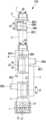
- FIG. 1is a schematic plan view a robot according to an embodiment of the present disclosure.
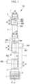
- FIG. 2is a schematic side view of a part at which a base and a rotational barrel are connected with each other in the robot in FIG. 1 .
- FIG. 3is a block diagram of torque control of a motor by a control unit of the robot in FIG. 1 .
- FIG. 4is a graph illustrating exemplary change of detection torque with the rotation angle of the rotational barrel about a shaft J 1 .
- FIG. 5is a graph illustrating exemplary correction torque calculated based on the detection torque illustrated in FIG. 4 .
- FIG. 6is a perspective view illustrating an exemplary first torque sensor included in the robot in FIG. 1 .
- the robot 100is a vertical articulated type robot including six joints rotated about respective axis lines.
- the robot 100includes a base 1 fixed to an installation surface, a rotational barrel (robot constitution component) 2 supported to the base 1 rotatably about a shaft (target joint) J 1 extending in the vertical direction, a first arm (robot constitution component) 3 supported to the rotational barrel 2 rotatably about a horizontal shaft (joint) J 2 orthogonal to the shaft J 1 , a second arm (robot constitution component) 4 supported to the first arm 3 rotatably about a shaft (joint) J 3 parallel to the shaft J 2 , a first wrist element (robot constitution component) 5 supported to the second arm 4 rotatably about a shaft (joint) J 4 twisted relative to the shaft J 3 , a second wrist element (robot constitution component) 6 supported to the first wrist element 5 rotatably about a shaft (joint) J 5 orthogonal to the shaft J 4 , and a third wrist element 7 supported to the second wrist element 6 rotatably about a shaft (joint)
- the robot 100also includes a first torque sensor (torque sensor) S 1 disposed between the base 1 and the rotational barrel 2 and configured to detect torque about the shaft J 1 , a second torque sensor S 2 disposed between the rotational barrel 2 and the first arm 3 and configured to detect torque about the shaft J 2 , and a third torque sensor S 3 disposed between the first arm 3 and the second arm 4 and configured to detect torque about the shaft J 3 .
- a first torque sensortorque sensor
- S 1torque sensor
- second torque sensor S 2disposed between the rotational barrel 2 and the first arm 3 and configured to detect torque about the shaft J 2
- a third torque sensor S 3disposed between the first arm 3 and the second arm 4 and configured to detect torque about the shaft J 3 .
- the robot 100also includes motors MT 1 to MT 6 configured to drive the components about the shafts J 1 to J 6 , encoders (angle information detection units) EN 1 to EN 6 included in the motors MT and configured to detect rotation angles about the shafts J 1 to J 6 , and a control unit 10 configured to control the drive of the components about the shafts J 1 to J 6 by using the detected rotation angles about the shafts.
- the motor MT 1which drives the rotational barrel 2 about the shaft J 1 relative to the base 1 , and the encoder EN 1 are illustrated in FIG. 2 but not in FIG. 1 .
- the control unit 10 illustrated in FIG. 1includes a CPU, a ROM, and a RAM (not illustrated).
- the control unit 10executes the function of a computer program stored in the ROM as the CPU loads the computer program onto the RAM.
- the control unit 10includes a change amount estimation unit (torque change amount estimation unit) 13 configured to calculate correction torque (change amount) Tf by estimating a change amount of torque detected by the first torque sensor S 1 in accordance with a posture change of the robot 100 , a correction unit 11 configured to correct detection torque T by using the correction torque Tf calculated by the change amount estimation unit 13 , and a drive unit 12 configured to drive the motor MT 1 based on a torque command value Ti input to drive the motor MT 1 , the detection torque T, and the correction torque Tf.
- a change amount estimation unittorque change amount estimation unit 13
- correction unit 11configured to correct detection torque T by using the correction torque Tf calculated by the change amount estimation unit 13
- a drive unit 12configured to drive the motor MT 1 based on a torque command value Ti input to drive the motor MT 1 , the detection torque T, and the correction torque Tf.
- the change amount estimation unit 13calculates and stores in advance (for example, at shipment), a rotation angle characteristic in the format of a table or approximate expression of the detection torque T detected by the torque sensor for the rotation angle when each joint is rotated about the shaft.
- FIG. 4illustrates torque TO detected by the first torque sensor S 1 when only the rotation angle about the shaft J 1 is changed and the other joints are fixed at such rotation angles that no load is applied on the shaft J 1 .
- Exemplary postures of the robot 100 in which no load is applied on the shaft J 1include a posture of the robot 100 in which the shafts J 4 and J 6 are aligned with an extended line of the shaft J 1 in effect, and a posture of the robot 100 in which the rotational barrel 2 and mechanisms on the tip side thereof are removed.
- the torque about the shaft J 1 detected by the first torque sensor S 1is ideally zero.
- two distortion gauges G 1 and G 2are bonded to the surface of a body BD of the first torque sensor S 1 as illustrated in FIG. 6 , and the detection torque T is determined based on a distortion amount detected by G 1 and G 2 . Error occurs to the detection torque T due to, for example, shift of the bonding positions of the distortion gauges G 1 and G 2 in some cases.
- the torque TOchanges in accordance with the rotation angle about the shaft J 1 detected by the first encoder EN 1 .
- the rotation angle characteristic of the torque TO detected by the first torque sensor S 1 as illustrated in FIG. 5is stored in the change amount estimation unit 13 in the format of a table or approximate expression.
- the rotation angle characteristics of torque for the rotation angles of all jointsare stored in the change amount estimation unit 13 in the format of a table or an approximate expression.
- the table or the approximate expressionis calculated by plotting data of the correlation between the rotation angle and torque by experiment. Coefficients of the table or the approximate expression are calculated from the plotted data.
- the rotation angle characteristics of torquemay be not only measured by actually operating the robot but also measured by simulation.
- the change amount estimation unitcan calculate the correction torque Tf by matching the rotation angles of the shafts detected by the encoders to the stored rotation angle characteristics or by performing interpolation.
- the correction unit 11calculates estimated actual torque Tr by subtracting the correction torque Tf estimated by the change amount estimation unit 13 from the detection torque T of the first torque sensor S 1 in the robot 100 in use as indicated in Expression (1) below.
- Estimated actual torque TrDetection torque T ⁇ Correction torque Tf (1)
- the estimated actual torque Trindicates actual torque applied to the shaft J 1 about the shaft J 1 , from which any load other than the torque about the shaft J 1 is removed.
- the correction unit 11may calculate the estimated actual torque Tr not only by subtracting the correction torque Tf from the detection torque T but also by using any calculation method of addition, multiplication, or division.
- the drive unit 12drives the motor MT 1 at a drive torque obtained by subtracting the estimated actual torque Tr from input torque Ti based on an input command for controlling the robot 100 .
- the detection torque T detected by the first torque sensor S 1includes torque caused by a load other than the torque about the shaft J 1 in some cases.
- the change amount estimation unit 13estimates the correction torque Tf as a change amount based on the rotation angle of each joint of the robot 100 and the stored rotation angle characteristics as illustrated in FIG. 3 .
- the correction unit 11corrects the detection torque T of the first torque sensor S 1 by using the correction torque Tf to obtain the estimated actual torque Tr as the detection torque T of the first torque sensor S 1 from which a load other than the torque about the shaft J 1 is removed. Accordingly, the torque about the shaft J 1 is accurately acquired as the estimated actual torque Tr, and thus the robot 100 can be accurately controlled.
- the correction unit 11does not need a value detected by a torque sensor other than the first torque sensor S 1 in calculation of the correction torque Tf for correcting the detection torque T about the shaft J 1 .
- the correction unit 11does not need a value detected by a torque sensor other than the first torque sensor S 1 in calculation of the correction torque Tf for correcting the detection torque T about the shaft J 1 .
- encodersare exemplarily described as angle information detection units, and the rotation angles about the shafts J 1 to J 6 are exemplarily described as information related to angles, but the present invention is not limited thereto.
- Angle speed or angle accelerationmay be detected.
- the angle speeds and/or angle accelerations about the shafts J 1 to J 6may be used in addition to the rotation angles about the shafts J 1 to J 6 when the correction torque Tf is calculated.
- information related to the angles of some joints, not all jointsmay be used when the correction torque Tf is calculated.
- the change amount estimation unit 13may store physical parameters (for example, sizes and weights) of the robot constitution components (such as the first arm 3 and the like) coupling the shafts J 1 to J 6 , and estimate the correction torque Tf based on the physical parameters and the rotation angles. In this case, the change amount estimation unit 13 can more accurately calculate the correction torque Tf by using inertia moment caused by an arm weight or the like and applied in a direction other than the direction about the shaft J 1 , and tensile force or compressive force applied in the direction along the shaft J 1 .
- the correction unit 11corrects the detection torque T of the first torque sensor S 1 , but similarly to the detection torque T of the first torque sensor S 1 , torque detected by the second torque sensor S 2 and torque detected by the third torque sensor S 3 may be each corrected by using the correction torque of the corresponding shaft.
- the robot 100may include a torque sensor configured to detect torque about the axis line of a joint (for example, the shaft J 4 ) different from that in the above-described embodiment.
- the correction unit 11 and the change amount estimation unit 13may be each provided to an optional component on the arms 3 and 4 of the robot 100 or provided inside a robot controller configured to control the robot 100 .
- the correction unit 11 and the change amount estimation unit 13may be each provided inside a peripheral device other than the arms 3 and 4 of the robot 100 and the robot controller, or installed as a separately provided control unit and connected with the robot controller.
- the correction unit 11 and the change amount estimation unit 13may be provided at places different from each other.
- An aspect of the present disclosureprovides a robot including: a plurality of joints each configured to rotate about an axis line; a torque sensor configured to detect torque about the axis line of a target joint as one of the plurality of joints; an angle information detection unit configured to detect information related to a rotation angle of each joint about the axis line; a torque change amount estimation unit configured to estimate a change amount of the torque detected by the torque sensor due to a load other than the torque about the axis line of the target joint based on the detected information; and a correction unit configured to correct the torque detected by the torque sensor by using the estimated change amount.
- torque about the axis lineis detected by the torque sensor.
- torque on which a load other than the torque about the axis line of the target joint is superimposedis detected by the torque sensor in some cases.
- the angle information detection unitdetects information related to the rotation angle of the joint about the axis line
- the torque change amount estimation unitestimates the change amount of torque due to a load other than torque about the axis line of the target joint based on the detected information. Then, the torque detected by the torque sensor is corrected by using the estimated change amount to remove the load other than the torque about the axis line of the target joint. Accordingly, the torque about the axis line of the target joint can be accurately acquired without providing a torque sensor to a joint other than the target joint, and the robot can be accurately controlled.
- the informationmay be the rotation angle of each joint about the axis line.
- the rotation angle of each jointis detected by the angle information detection unit, and torque can be corrected using the change amount of a load estimated in accordance with change in the posture of the robot.
- the informationmay be an angle speed or angle acceleration of each joint about the axis line.
- the angle speed or angle acceleration of each jointis detected by the angle information detection unit, and the change amount of a load is estimated in accordance with the detected angle speed or angle acceleration.
- the above-described aspectmay further include a robot constitution component configured to couple the joints, and the information may be information of a load on each joint, which is calculated from a rotation angle, angle speed, or angle acceleration of each joint about the axis line, and a physical parameter of the robot constitution component.
- the angle information detection unitcalculates, as information related to the rotation angle, load information such as inertia moment, tensile force, or compressive force based on the detected rotation angle, angle speed, or angle acceleration and the physical parameter of the robot constitution component.
- load informationsuch as inertia moment, tensile force, or compressive force based on the detected rotation angle, angle speed, or angle acceleration and the physical parameter of the robot constitution component.
- a load other than torque applied to the target joint about the axis lineis calculated based on the calculated load information, and accordingly, torque about the axis line of the target joint can be accurately acquired.
- the load other than the torque about the axis line of the target jointmay be torque about an orthogonal axis line disposed in a plane orthogonal to the axis line of the target joint.
- the load other than the torque about the axis line of the target jointmay be a tensile or compressive load acting in a direction along the axis line of the target joint.
- the correction unitmay correct the torque detected by the torque sensor based on a torque characteristic indicating a relation between the torque detected by the torque sensor and the information of the target joint detected by the angle information detection unit when the target joint is rotated about the axis line of the target joint while no load other than the torque about the axis line of the target joint is applied.
- the torque characteristicindicates a torque change amount in response to change in a value detected by the angle information detection unit while the torque about the axis line of the target joint is not applied to the target joint.
- the torque characteristicindicates a characteristic attributable to a detection error of the torque sensor, and thus the torque about the axis line of the target joint can be more accurately acquired by correcting a detection torque by using the torque characteristic.
Landscapes
- Engineering & Computer Science (AREA)
- Robotics (AREA)
- Mechanical Engineering (AREA)
- Human Computer Interaction (AREA)
- Automation & Control Theory (AREA)
- Manipulator (AREA)
Abstract
Description
Estimated actual torqueTr=Detection torqueT−Correction torqueTf (1)
Claims (7)
Applications Claiming Priority (4)
| Application Number | Priority Date | Filing Date | Title |
|---|---|---|---|
| JP2018-163182 | 2018-08-31 | ||
| JP2018163182 | 2018-08-31 | ||
| JP2019035508AJP6943906B2 (en) | 2018-08-31 | 2019-02-28 | robot |
| JP2019-035508 | 2019-02-28 |
Publications (2)
| Publication Number | Publication Date |
|---|---|
| US20200070357A1 US20200070357A1 (en) | 2020-03-05 |
| US11691293B2true US11691293B2 (en) | 2023-07-04 |
Family
ID=69526888
Family Applications (1)
| Application Number | Title | Priority Date | Filing Date |
|---|---|---|---|
| US16/540,682Active2040-05-15US11691293B2 (en) | 2018-08-31 | 2019-08-14 | Robot |
Country Status (3)
| Country | Link |
|---|---|
| US (1) | US11691293B2 (en) |
| CN (1) | CN110871456B (en) |
| DE (1) | DE102019122416B4 (en) |
Families Citing this family (6)
| Publication number | Priority date | Publication date | Assignee | Title |
|---|---|---|---|---|
| JP7451940B2 (en)* | 2019-10-31 | 2024-03-19 | セイコーエプソン株式会社 | Control method and calculation device |
| US11821781B2 (en)* | 2020-07-20 | 2023-11-21 | Progress Mfg. Llc | Apparatus and method for determining weight distribution |
| CN116685448A (en)* | 2020-11-27 | 2023-09-01 | 株式会社不二越 | Force detection device and robot system |
| US20240001548A1 (en)* | 2021-01-18 | 2024-01-04 | Fanuc Corporation | Robot system comprising robot including torque sensors |
| US20250033220A1 (en)* | 2021-12-20 | 2025-01-30 | Fanuc Corporation | Control device for robot performing mastering through torque or force control |
| CN115290249B (en)* | 2022-06-24 | 2025-04-29 | 遨博(北京)智能科技股份有限公司 | Method and system for calibrating torque sensor of robot joint |
Citations (19)
| Publication number | Priority date | Publication date | Assignee | Title |
|---|---|---|---|---|
| JPS6274594A (en) | 1985-09-30 | 1987-04-06 | 松下電器産業株式会社 | Force sensor calibration method for robotic equipment |
| JPH04148307A (en) | 1990-10-11 | 1992-05-21 | Hitachi Metals Ltd | Detecting method for working force for force control robot |
| EP1915963A1 (en) | 2006-10-25 | 2008-04-30 | The European Atomic Energy Community (EURATOM), represented by the European Commission | Force estimation for a minimally invasive robotic surgery system |
| US20110178639A1 (en)* | 2010-01-18 | 2011-07-21 | Samsung Electronics Co., Ltd. | Humanoid robot and walking control method thereof |
| US20120065781A1 (en)* | 2010-09-15 | 2012-03-15 | Kabushiki Kaisha Yaskawa Denki | Reducer abnormality determination method, abnormality determination device, and robot system |
| US20120316683A1 (en)* | 2011-06-10 | 2012-12-13 | Samsung Electronics Co., Ltd. | Balance control apparatus of robot and control method thereof |
| JP2013018075A (en) | 2011-07-11 | 2013-01-31 | Seiko Epson Corp | Robot, robot controller, robot control method, and program |
| US20150290809A1 (en) | 2014-04-09 | 2015-10-15 | Fanuc Corporation | Human-cooperative industrial robot with lead-through function |
| US20150367510A1 (en)* | 2014-06-20 | 2015-12-24 | Fanuc Corporation | Multi-joint robot having function for repositioning arm |
| US20160067865A1 (en) | 2014-09-09 | 2016-03-10 | Honda Motor Co., Ltd. | Control system for power unit |
| DE102016002933A1 (en) | 2016-03-10 | 2016-08-25 | Daimler Ag | Method for controlling a robot and robot |
| WO2016152046A1 (en) | 2015-03-23 | 2016-09-29 | Sony Corporation | Medical support arm device and method of controlling medical support arm device |
| JP2016179168A (en) | 2015-03-23 | 2016-10-13 | ソニー株式会社 | Medical support arm device, method for controlling medical support arm device, and medical observation device |
| DE102016108077A1 (en) | 2015-05-08 | 2016-11-10 | Fanuc Corporation | Method for setting load parameters and device for setting load parameters |
| DE112010004664B4 (en) | 2009-12-02 | 2016-11-10 | Honda Motor Co., Ltd. | Control device for a drive device |
| US20170113346A1 (en) | 2015-10-27 | 2017-04-27 | Canon Kabushiki Kaisha | Driving mechanism, robot apparatus measurement method, robot apparatus control method and component manufacturing method |
| US20170165834A1 (en) | 2015-12-10 | 2017-06-15 | Cambridge Medical Robotics Limited | Measuring robot performance |
| US20190275674A1 (en)* | 2016-12-16 | 2019-09-12 | Panasonic Intellectual Property Management Co., Ltd. | Method for controlling robot |
| US20210116315A1 (en)* | 2018-07-02 | 2021-04-22 | Nidec Copal Electronics Corporation | Torque sensor supporting device |
Family Cites Families (5)
| Publication number | Priority date | Publication date | Assignee | Title |
|---|---|---|---|---|
| JPH0683453A (en)* | 1992-09-03 | 1994-03-25 | Mitsubishi Heavy Ind Ltd | Load compensation control method for robot |
| CN105432015A (en)* | 2013-08-09 | 2016-03-23 | 株式会社安川电机 | Motor drive system and motor control device |
| KR20180067652A (en)* | 2015-10-30 | 2018-06-20 | 카와사키 주코교 카부시키 카이샤 | Monitoring system of robot system |
| CN107538494A (en)* | 2016-06-29 | 2018-01-05 | 沈阳新松机器人自动化股份有限公司 | A kind of robot control method and system based on torque sensor and encoder |
| CN108015799B (en)* | 2017-12-29 | 2024-02-09 | 重庆卓来科技有限责任公司 | Single encoder modularized joint and joint position determining method |
- 2019
- 2019-08-14USUS16/540,682patent/US11691293B2/enactiveActive
- 2019-08-21DEDE102019122416.0Apatent/DE102019122416B4/enactiveActive
- 2019-08-27CNCN201910795881.3Apatent/CN110871456B/enactiveActive
Patent Citations (29)
| Publication number | Priority date | Publication date | Assignee | Title |
|---|---|---|---|---|
| JPS6274594A (en) | 1985-09-30 | 1987-04-06 | 松下電器産業株式会社 | Force sensor calibration method for robotic equipment |
| JPH04148307A (en) | 1990-10-11 | 1992-05-21 | Hitachi Metals Ltd | Detecting method for working force for force control robot |
| US20130012930A1 (en) | 2006-10-25 | 2013-01-10 | The European Atomic Energy Community (Euratom), Represented By The European Commission | Force estimation for a minimally invasive robotic surgery system |
| EP1915963A1 (en) | 2006-10-25 | 2008-04-30 | The European Atomic Energy Community (EURATOM), represented by the European Commission | Force estimation for a minimally invasive robotic surgery system |
| US20100094312A1 (en) | 2006-10-25 | 2010-04-15 | The European Atomic Energy Community (Euratom), Represented By The European Commission | Force estimation for a minimally invasive robotic surgery system |
| US20180194013A1 (en) | 2006-10-25 | 2018-07-12 | The European Atomic Energy Community (Euratom), Represented By The European Commission | Force estimation for a minimally invasive robotic surgery system |
| EP2491884A1 (en) | 2006-10-25 | 2012-08-29 | The European Atomic Energy Community (EURATOM), represented by the European Commission | Force estimation for a minimally invasive robotic surgery system |
| JP2012254303A (en) | 2006-10-25 | 2012-12-27 | European Atomic Energy Community (Euratom) Represented By The European Commission | Force estimation for minimally invasive robotic surgery system |
| DE112010004664B4 (en) | 2009-12-02 | 2016-11-10 | Honda Motor Co., Ltd. | Control device for a drive device |
| US20110178639A1 (en)* | 2010-01-18 | 2011-07-21 | Samsung Electronics Co., Ltd. | Humanoid robot and walking control method thereof |
| US20120065781A1 (en)* | 2010-09-15 | 2012-03-15 | Kabushiki Kaisha Yaskawa Denki | Reducer abnormality determination method, abnormality determination device, and robot system |
| US20120316683A1 (en)* | 2011-06-10 | 2012-12-13 | Samsung Electronics Co., Ltd. | Balance control apparatus of robot and control method thereof |
| JP2013018075A (en) | 2011-07-11 | 2013-01-31 | Seiko Epson Corp | Robot, robot controller, robot control method, and program |
| US20150290809A1 (en) | 2014-04-09 | 2015-10-15 | Fanuc Corporation | Human-cooperative industrial robot with lead-through function |
| JP2015199174A (en) | 2014-04-09 | 2015-11-12 | ファナック株式会社 | Human-robot cooperative type industrial robot having lead-through function |
| US20150367510A1 (en)* | 2014-06-20 | 2015-12-24 | Fanuc Corporation | Multi-joint robot having function for repositioning arm |
| US20160067865A1 (en) | 2014-09-09 | 2016-03-10 | Honda Motor Co., Ltd. | Control system for power unit |
| JP2016057812A (en) | 2014-09-09 | 2016-04-21 | 本田技研工業株式会社 | Power system control system |
| WO2016152046A1 (en) | 2015-03-23 | 2016-09-29 | Sony Corporation | Medical support arm device and method of controlling medical support arm device |
| JP2016179168A (en) | 2015-03-23 | 2016-10-13 | ソニー株式会社 | Medical support arm device, method for controlling medical support arm device, and medical observation device |
| US20180021094A1 (en)* | 2015-03-23 | 2018-01-25 | Sony Production | Medical support arm device and method of controlling medical support arm device |
| DE102016108077A1 (en) | 2015-05-08 | 2016-11-10 | Fanuc Corporation | Method for setting load parameters and device for setting load parameters |
| US20170113346A1 (en) | 2015-10-27 | 2017-04-27 | Canon Kabushiki Kaisha | Driving mechanism, robot apparatus measurement method, robot apparatus control method and component manufacturing method |
| EP3162516A2 (en) | 2015-10-27 | 2017-05-03 | Canon Kabushiki Kaisha | Driving mechanism, robot apparatus measurement method, robot apparatus control method and component manufacturing method |
| JP2017080841A (en) | 2015-10-27 | 2017-05-18 | キヤノン株式会社 | Robot arm joint structure, robot apparatus measurement method, and robot apparatus control method |
| US20170165834A1 (en) | 2015-12-10 | 2017-06-15 | Cambridge Medical Robotics Limited | Measuring robot performance |
| DE102016002933A1 (en) | 2016-03-10 | 2016-08-25 | Daimler Ag | Method for controlling a robot and robot |
| US20190275674A1 (en)* | 2016-12-16 | 2019-09-12 | Panasonic Intellectual Property Management Co., Ltd. | Method for controlling robot |
| US20210116315A1 (en)* | 2018-07-02 | 2021-04-22 | Nidec Copal Electronics Corporation | Torque sensor supporting device |
Non-Patent Citations (3)
| Title |
|---|
| German Office Action dated Nov. 23, 2022, for German Patent Application No. 10 2019 122 416.0. |
| Japanese Notice of Reasons for Refusal dated Feb. 2, 2021, for Japanese Patent Application No. 2019035508. |
| Japanese Search Report by Registered Search Organization dated Jan. 26, 2021, for Japanese Patent Application No. 2019035508. |
Also Published As
| Publication number | Publication date |
|---|---|
| DE102019122416B4 (en) | 2023-05-17 |
| CN110871456A (en) | 2020-03-10 |
| US20200070357A1 (en) | 2020-03-05 |
| DE102019122416A1 (en) | 2020-03-05 |
| CN110871456B (en) | 2024-02-06 |
Similar Documents
| Publication | Publication Date | Title |
|---|---|---|
| US11691293B2 (en) | Robot | |
| JP7719155B2 (en) | Robot system, control method, article manufacturing method, control program, and recording medium | |
| JP2645004B2 (en) | Control device for multi-degree-of-freedom manipulator | |
| KR102469258B1 (en) | Robot adaptive placement system with end-effector position estimation | |
| TWI642523B (en) | Gravity compensation method for load estimation of mechanical arm and gravity compensation system for load estimation | |
| US9329092B2 (en) | Method for determining a torque and an industrial robot | |
| EP2492061B1 (en) | Robot System, Robot Control Apparatus, and Robot Control Method | |
| CN110340909B (en) | Robot system for learning control using motor encoder and sensor | |
| JP6044511B2 (en) | Robot control method and robot system | |
| JP5849451B2 (en) | Robot failure detection method, control device, and robot | |
| CN111376267A (en) | Industrial Robot System | |
| JP2016168650A (en) | Robot device, robot control method, program, and storage medium | |
| KR20110004788A (en) | Method and apparatus for operating the manipulator | |
| US11141855B2 (en) | Robot system, method of controlling robot arm, recording medium, and method of manufacturing an article | |
| JP2017124455A (en) | Robot apparatus, robot control method, program, and recording medium | |
| JP7015276B2 (en) | Industrial robot system | |
| JP5752565B2 (en) | Robot arm | |
| JP6943906B2 (en) | robot | |
| US20230101098A1 (en) | Robot control device | |
| JPH06332535A (en) | Robot controller | |
| JP5473889B2 (en) | Force control device | |
| CN115916488A (en) | robot controller | |
| JP7695565B2 (en) | Force detection device and robot system | |
| KR102826169B1 (en) | Spring constant compensation device and method thereof and recording medium | |
| JP2019111597A (en) | Robot arm and robot device |
Legal Events
| Date | Code | Title | Description |
|---|---|---|---|
| FEPP | Fee payment procedure | Free format text:ENTITY STATUS SET TO UNDISCOUNTED (ORIGINAL EVENT CODE: BIG.); ENTITY STATUS OF PATENT OWNER: LARGE ENTITY | |
| AS | Assignment | Owner name:FANUC CORPORATION, JAPAN Free format text:ASSIGNMENT OF ASSIGNORS INTEREST;ASSIGNORS:NAKAYAMA, KAZUTAKA;OGURI, KENICHIRO;REEL/FRAME:050103/0398 Effective date:20190524 | |
| STPP | Information on status: patent application and granting procedure in general | Free format text:DOCKETED NEW CASE - READY FOR EXAMINATION | |
| STPP | Information on status: patent application and granting procedure in general | Free format text:NON FINAL ACTION MAILED | |
| STPP | Information on status: patent application and granting procedure in general | Free format text:RESPONSE TO NON-FINAL OFFICE ACTION ENTERED AND FORWARDED TO EXAMINER | |
| STPP | Information on status: patent application and granting procedure in general | Free format text:FINAL REJECTION MAILED | |
| STPP | Information on status: patent application and granting procedure in general | Free format text:ADVISORY ACTION MAILED | |
| STPP | Information on status: patent application and granting procedure in general | Free format text:DOCKETED NEW CASE - READY FOR EXAMINATION | |
| STPP | Information on status: patent application and granting procedure in general | Free format text:NON FINAL ACTION MAILED | |
| STCF | Information on status: patent grant | Free format text:PATENTED CASE |