US11689045B2 - Near-held wireless power transmission techniques - Google Patents
Near-held wireless power transmission techniquesDownload PDFInfo
- Publication number
- US11689045B2 US11689045B2US17/210,398US202117210398AUS11689045B2US 11689045 B2US11689045 B2US 11689045B2US 202117210398 AUS202117210398 AUS 202117210398AUS 11689045 B2US11689045 B2US 11689045B2
- Authority
- US
- United States
- Prior art keywords
- wireless
- field
- power receiver
- energy
- power
- Prior art date
- Legal status (The legal status is an assumption and is not a legal conclusion. Google has not performed a legal analysis and makes no representation as to the accuracy of the status listed.)
- Active, expires
Links
- 230000005540biological transmissionEffects0.000titleclaimsabstractdescription34
- 238000000034methodMethods0.000titleclaimsdescription80
- 238000004891communicationMethods0.000claimsdescription136
- 238000003860storageMethods0.000claimsdescription10
- 230000007423decreaseEffects0.000claimsdescription8
- 229910052751metalInorganic materials0.000abstractdescription17
- 239000002184metalSubstances0.000abstractdescription17
- 238000012546transferMethods0.000description50
- 239000000758substrateSubstances0.000description46
- 239000010410layerSubstances0.000description40
- 238000010586diagramMethods0.000description30
- 230000004044responseEffects0.000description21
- 230000006870functionEffects0.000description20
- 230000008569processEffects0.000description14
- 230000008878couplingEffects0.000description10
- 238000010168coupling processMethods0.000description10
- 238000005859coupling reactionMethods0.000description10
- 239000000463materialSubstances0.000description10
- 238000006243chemical reactionMethods0.000description9
- 230000008859changeEffects0.000description6
- 230000003750conditioning effectEffects0.000description6
- 230000005611electricityEffects0.000description6
- 230000000737periodic effectEffects0.000description6
- 230000033228biological regulationEffects0.000description5
- 238000005516engineering processMethods0.000description5
- 230000001939inductive effectEffects0.000description5
- 239000004033plasticSubstances0.000description5
- 229920003023plasticPolymers0.000description5
- 239000000919ceramicSubstances0.000description4
- 230000005670electromagnetic radiationEffects0.000description4
- 239000011159matrix materialSubstances0.000description4
- 229920001690polydopaminePolymers0.000description4
- 230000000644propagated effectEffects0.000description4
- 230000003044adaptive effectEffects0.000description3
- 230000001413cellular effectEffects0.000description3
- 239000004020conductorSubstances0.000description3
- 238000013461designMethods0.000description3
- 239000002344surface layerSubstances0.000description3
- RYGMFSIKBFXOCR-UHFFFAOYSA-NCopperChemical compound[Cu]RYGMFSIKBFXOCR-UHFFFAOYSA-N0.000description2
- 229920001875EbonitePolymers0.000description2
- 230000003213activating effectEffects0.000description2
- 230000015572biosynthetic processEffects0.000description2
- 238000004590computer programMethods0.000description2
- 229910052802copperInorganic materials0.000description2
- 239000010949copperSubstances0.000description2
- 238000001514detection methodMethods0.000description2
- 230000000694effectsEffects0.000description2
- 239000011521glassSubstances0.000description2
- 230000033001locomotionEffects0.000description2
- 238000010295mobile communicationMethods0.000description2
- 230000003287optical effectEffects0.000description2
- 238000012545processingMethods0.000description2
- 230000000717retained effectEffects0.000description2
- 238000009825accumulationMethods0.000description1
- 238000003491arrayMethods0.000description1
- 239000012237artificial materialSubstances0.000description1
- 230000006399behaviorEffects0.000description1
- 230000008901benefitEffects0.000description1
- 239000003990capacitorSubstances0.000description1
- 230000001143conditioned effectEffects0.000description1
- 230000001276controlling effectEffects0.000description1
- PMHQVHHXPFUNSP-UHFFFAOYSA-Mcopper(1+);methylsulfanylmethane;bromideChemical compoundBr[Cu].CSCPMHQVHHXPFUNSP-UHFFFAOYSA-M0.000description1
- 230000001808coupling effectEffects0.000description1
- 238000011982device technologyMethods0.000description1
- 230000005672electromagnetic fieldEffects0.000description1
- -1filtersSubstances0.000description1
- 238000001914filtrationMethods0.000description1
- 238000003306harvestingMethods0.000description1
- 230000006698inductionEffects0.000description1
- 230000000977initiatory effectEffects0.000description1
- 238000004519manufacturing processMethods0.000description1
- 238000013507mappingMethods0.000description1
- 230000007246mechanismEffects0.000description1
- 238000012986modificationMethods0.000description1
- 230000004048modificationEffects0.000description1
- 230000010287polarizationEffects0.000description1
- 230000001902propagating effectEffects0.000description1
- 230000001681protective effectEffects0.000description1
- 230000005855radiationEffects0.000description1
- 230000001105regulatory effectEffects0.000description1
- 239000005060rubberSubstances0.000description1
- 239000007787solidSubstances0.000description1
- 230000000007visual effectEffects0.000description1
- XLYOFNOQVPJJNP-UHFFFAOYSA-NwaterSubstancesOXLYOFNOQVPJJNP-UHFFFAOYSA-N0.000description1
- 239000002023woodSubstances0.000description1
Images


Classifications
- H—ELECTRICITY
- H02—GENERATION; CONVERSION OR DISTRIBUTION OF ELECTRIC POWER
- H02J—CIRCUIT ARRANGEMENTS OR SYSTEMS FOR SUPPLYING OR DISTRIBUTING ELECTRIC POWER; SYSTEMS FOR STORING ELECTRIC ENERGY
- H02J7/00—Circuit arrangements for charging or depolarising batteries or for supplying loads from batteries
- H02J7/02—Circuit arrangements for charging or depolarising batteries or for supplying loads from batteries for charging batteries from AC mains by converters
- H02J7/04—Regulation of charging current or voltage
- H—ELECTRICITY
- H02—GENERATION; CONVERSION OR DISTRIBUTION OF ELECTRIC POWER
- H02J—CIRCUIT ARRANGEMENTS OR SYSTEMS FOR SUPPLYING OR DISTRIBUTING ELECTRIC POWER; SYSTEMS FOR STORING ELECTRIC ENERGY
- H02J50/00—Circuit arrangements or systems for wireless supply or distribution of electric power
- H02J50/10—Circuit arrangements or systems for wireless supply or distribution of electric power using inductive coupling
- H—ELECTRICITY
- H02—GENERATION; CONVERSION OR DISTRIBUTION OF ELECTRIC POWER
- H02J—CIRCUIT ARRANGEMENTS OR SYSTEMS FOR SUPPLYING OR DISTRIBUTING ELECTRIC POWER; SYSTEMS FOR STORING ELECTRIC ENERGY
- H02J50/00—Circuit arrangements or systems for wireless supply or distribution of electric power
- H02J50/20—Circuit arrangements or systems for wireless supply or distribution of electric power using microwaves or radio frequency waves
- H02J50/23—Circuit arrangements or systems for wireless supply or distribution of electric power using microwaves or radio frequency waves characterised by the type of transmitting antennas, e.g. directional array antennas or Yagi antennas
- H—ELECTRICITY
- H04—ELECTRIC COMMUNICATION TECHNIQUE
- H04B—TRANSMISSION
- H04B1/00—Details of transmission systems, not covered by a single one of groups H04B3/00 - H04B13/00; Details of transmission systems not characterised by the medium used for transmission
- H04B1/38—Transceivers, i.e. devices in which transmitter and receiver form a structural unit and in which at least one part is used for functions of transmitting and receiving
- H04B1/3827—Portable transceivers
- H04B1/3883—Arrangements for mounting batteries or battery chargers
- H—ELECTRICITY
- H04—ELECTRIC COMMUNICATION TECHNIQUE
- H04W—WIRELESS COMMUNICATION NETWORKS
- H04W8/00—Network data management
- H04W8/005—Discovery of network devices, e.g. terminals
- H—ELECTRICITY
- H02—GENERATION; CONVERSION OR DISTRIBUTION OF ELECTRIC POWER
- H02J—CIRCUIT ARRANGEMENTS OR SYSTEMS FOR SUPPLYING OR DISTRIBUTING ELECTRIC POWER; SYSTEMS FOR STORING ELECTRIC ENERGY
- H02J2310/00—The network for supplying or distributing electric power characterised by its spatial reach or by the load
- H02J2310/10—The network having a local or delimited stationary reach
- H02J2310/20—The network being internal to a load
- H02J2310/22—The load being a portable electronic device
- H—ELECTRICITY
- H02—GENERATION; CONVERSION OR DISTRIBUTION OF ELECTRIC POWER
- H02J—CIRCUIT ARRANGEMENTS OR SYSTEMS FOR SUPPLYING OR DISTRIBUTING ELECTRIC POWER; SYSTEMS FOR STORING ELECTRIC ENERGY
- H02J7/00—Circuit arrangements for charging or depolarising batteries or for supplying loads from batteries
- H02J7/0013—Circuit arrangements for charging or depolarising batteries or for supplying loads from batteries acting upon several batteries simultaneously or sequentially
- H—ELECTRICITY
- H02—GENERATION; CONVERSION OR DISTRIBUTION OF ELECTRIC POWER
- H02J—CIRCUIT ARRANGEMENTS OR SYSTEMS FOR SUPPLYING OR DISTRIBUTING ELECTRIC POWER; SYSTEMS FOR STORING ELECTRIC ENERGY
- H02J7/00—Circuit arrangements for charging or depolarising batteries or for supplying loads from batteries
- H02J7/0042—Circuit arrangements for charging or depolarising batteries or for supplying loads from batteries characterised by the mechanical construction
Definitions
- a method for wireless power transfercomprises transmitting, by an antenna of the first device, one or more RF signals to a second device in a proximity to the first device, wherein the second device comprises a first antenna configured to receive the one or more RF signals from the first device, and a battery configured to be charged in response to the second device receiving the one or more RF signals from the first device when the second device is within the proximity to the first device.
- FIG. 3 Bis a flow diagram illustrating operation of the illustrative electronic device in accordance with one or more embodiments of the present disclosure
- FIG. 6 Dillustrates an overhead view of the example embodiment of the unit cell illustrated in FIG. 6 C , in accordance with an embodiment of the present disclosure
- the unit cellsdo not leak or have minimal leakage of the RF energy signal.
- the unit cellsare adaptably configured to allow the RF energy signal to leak from the unit cells to an antenna of the electronic device 104 when the receive antenna is positioned within the near-field distance from the unit cell, and is tuned to the frequency of the RF energy signal (or is otherwise configured to receive the RF energy signal).
- one embodiment of an antennais considered “tuned” to a particular frequency when leakage of an RF energy signal from the charging surface 102 with metamaterial occurs.
- One or more surfaces of the unit cellmay be formed using metamaterial. For example, a ground plane, antenna patch, and/or both may be formed of metamaterial depending on design criteria.
- a power amplifier (not shown) and gain control circuitry (not shown)may be applied to each antenna 204 .
- the use of one or more power amplifiers to amplify an RF signalan RF signal that is supplied to or generated within the charging surface 102 ) in order to generate an RF energy signal (the signal that is applied to the antennas 204 ) to feed each of the multiple antennas 204 provides for reduced circuitry and lower cost.
- four RF input portsmay be used to feed the antennas 204 of the charging surface 102 .
- a single RF input port or RF generator internal to the charging surface 102may support a certain number or ratio of antennas 204 .
- the size of the aperture 606is determined in accordance with the periodic frequency of the RF energy signal generated by the patch antenna 610 such that the RF energy signal does not or has minimal leakage from the aperture 606 of the unit cells 602 unless an antenna tuned to the frequency of the RF energy signal is positioned in a near-field distance from at least one of the unit cells 602 .
- the aperture 606may be altered in dimension depending on frequency of the RF energy signal so as to be properly tuned for preventing leakage of the RF energy signal when no electronic device is positioned in the near-field. It should be understood that a number of layers of the unit cell may vary depending on the application, where different number of layers may provide different responses from the unit cells to provide different harmonic responses (e.g., higher or shifted harmonic frequencies for different wireless powering applications).
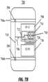
- the charging surface 700is shown to include a cover 802 within which a first cavity 804 a and a second cavity 804 b (collectively 804 ) are formed by a ground plane 806 that separates the two cavities 804 .
- the ground planemay be formed of metamaterial, as described herein.
- the charging surface 700may also include one or more touch points 810 from which an RF energy signal emanates.
- a first stagemay provide for an RF energy signal being fed through a feeding point (e.g., slot on a ground plane) into the first cavity 804 a and gets trapped in the structure of the first cavity 804 a .
- the communications component 310may, in some embodiments, transmit a signal to the charging surface 700 to request that the charging be suspended or discontinued. This may happen, for example, if the battery 312 of the electronic device 104 is completely charged or reaches a desired charge level, the electronic device 104 is being turned off, the communications component 310 is being turned off or moved out of communication range with the communications component 210 , or for other reasons. In another embodiment, in the event that the electronic device is no longer being sensed, electronically, physically or otherwise depending on the sensor being utilized, then the communications component 210 may be turned off.
- FIG. 11 A and FIG. 11 Billustrate perspective and cross-sectional views, respectively, of a representative unit cell 1102 comprising an embodiment of the charging surface 102 , where each unit cell 1102 has a harmonic filter element 1104 positioned on a top surface of the unit cell 1102 .
- the unit cell 1102 illustrated in FIGS. 11 A and 11 Bis similar to that described above and shown in FIGS. 6 A- 6 D , however, the harmonic filter element 1104 may be placed on a top surface of unit cells of a different embodiment, such as the embodiment described above and illustrated in FIGS. 5 A- 5 D .
- Non-limiting examples of the various types of information that may be included in communications signalsmay also include a beacon message, a device identifier (device ID) for first device 1302 , a user identifier (user ID) for the first device 1302 , the battery level for the second device 1304 , the second device 1304 location, and other such information.
- device IDdevice identifier
- user IDuser identifier
- the communications componentmay operate based on any number of communication protocols, such as Bluetooth®, Wireless Fidelity (Wi-Fi), Near-Field Communications (NFC), ZigBee, and others.
- Wi-FiWireless Fidelity
- NFCNear-Field Communications
- ZigBeeZigBee
- the communication componentis not limited to radio-frequency based technologies, but may include radar, infrared, and sound devices for sonic triangulation of other devices, like the second device 1404 .
Landscapes
- Engineering & Computer Science (AREA)
- Computer Networks & Wireless Communication (AREA)
- Power Engineering (AREA)
- Signal Processing (AREA)
- Databases & Information Systems (AREA)
- Charge And Discharge Circuits For Batteries Or The Like (AREA)
Abstract
Description
This is a continuation of U.S. Non-Provisional patent application Ser. No. 16/726,753, entitled “Near-Field Wireless Power Transmission Techniques For A Wireless-Power Receiver,” filed Dec. 24, 2019 which is a continuation of U.S. Non-Provisional patent application Ser. No. 16/051,336, entitled “Unit Cell Of A Wireless Power Transmitter For Wireless Power Charging,” filed Jul. 31, 2018 (now U.S. Pat. No. 10,516,289) which is a continuation of U.S. Non-Provisional patent application Ser. No. 15/047,831, entitled “Systems and Methods of Wireless Power Charging Through Multiple Receiver Devices, filed Feb. 19, 2016, (now U.S. Pat. No. 10,038,332), which claims the benefit of U.S. Provisional Patent Application Ser. No. 62/271,837, entitled “Systems and Methods of Wireless Power Charging through Multiple Receiving Devices,” filed Dec. 28, 2015, and U.S. Provisional Patent Application Ser. No. 62/387,465, entitled “Systems and Methods of Wireless Power Charging through Multiple Receiving Devices,” filed Dec. 24, 2015, each of which is incorporated by reference herein in its entirety.
Generally, the present disclosure relates to wireless charging. More particularly, the present disclosure relates to low-power near field charging surfaces.
Electronic devices, such as laptop computers, smartphones, portable gaming devices, tablets, or others, require power to operate. As generally understood, electronic equipment is often charged at least once a day, or in high-use or power-hungry electronic devices, more than once a day. Such activity may be tedious and may present a burden to some users. For example, a user may be required to carry chargers in case his electronic equipment is lacking power. In addition, some users have to find available power sources to connect to, which is time consuming. Lastly, some users must plug into a wall or some other power supply to be able to charge their electronic device. However, such activity may render electronic devices inoperable or not portable during charging.
Some conventional solutions include an inductive charging pad, which may employ magnetic induction or resonating coils. As understood in the art, such a solution still requires the electronic devices to: (i) be placed in a specific location on the inductive charging pad, and (ii) be particularly oriented for powering due to electromagnetic fields having a particular orientation. Furthermore, inductive charging units require large coils in both devices (i.e., the charger and the device being charged by the charger), which may not desirable due to size and cost, for example. Therefore, electronic devices may not sufficiently charge or may not receive a charge if not oriented properly on the inductive charging pad. And, users can be frustrated when an electronic device is not charged as expected after using a charging mat, thereby destroying the credibility of the charging mat.
Other conventional solutions use far field RF wave transmission to create pockets of energy at remote locations for charging a device. Such solutions, however, are better suited for particular uses and configurations as far field RF wave transmission solutions typically use numerous antenna arrays and circuitry for providing phase and amplitude control of the RF waves. Accordingly, there is a desire for an economical application of a charging surface that allows for low-power, wireless charging without requiring a particular orientation for providing a sufficient charge.
In one embodiment, the present disclosure provides a method for charging an electronic device, the method comprising applying an RF signal to a charging surface having a plurality of unit cells to cause an RF energy signal to be present within the unit cells of the charging surface for charging the electronic device in response to an antenna of the electronic device being positioned in a near-field distance from at least one of the unit cells. The unit cells may at least in part be a periodic structure, where the periodic structure may be locally periodic while being adaptive as function of location within the structure.
In one embodiment, the present disclosure provides a charging surface device comprising: circuitry configured to generate an RF signal; and a plurality of unit cells configured to receive the RF signal and cause an RF energy signal to be present for charging an electronic device in response to an antenna of the electronic device being positioned in a near-field distance measured from a surface of at least one of the unit cells.
In one embodiment, the present disclosure provides a method for charging an electronic device, the method comprising: applying an RF signal to a plurality of unit cells of a charging surface to cause an RF energy signal to be present within the unit cells of the charging surface; receiving the RF energy signal at an antenna of a wireless device when the antenna is positioned in a near-field distance from at least one of the unit cells; and charging a battery of the electronic device in response to the antenna receiving the RF energy signal.
In one embodiment, the present disclosure provides a system comprising: RF circuitry configured to generate an RF signal; an adaptive coupling surface (here, a charging surface) comprising a plurality of unit cells configured to receive the RF signal and to cause an RF energy signal to be trapped/stored within the unit cells when the receiver device is not present and to leak the energy when the receiver is within a near-field region of the surface. Receiver circuitry of an electronic device to be charged may be configured to charge the electronic device in response to an antenna of the electronic device receiving the RF energy signal when the antenna is positioned in a near-field distance from one or more of the unit cells (of the coupling surface).
In one embodiment, the present disclosure provides a method for charging an electronic device, the method comprising: generating an RF signal; applying the RF signal, by a conductive line extending through a via, to a patch antenna member of a unit cell (i.e., located within the coupling surface, where the patent antenna member or exciting element may be a part of the coupling surface design (e.g., one of the unit cells) or the exciting element may be an additional element placed within the other unit cells); generating, by the patch antenna, an RF energy signal in the unit cell; and leaking the RF energy signal from the unit cell to an antenna of the electronic device when the antenna is positioned in a near-field distance from the unit cell.
In one embodiment, the present disclosure provides a charging surface device comprising: a plurality of unit cells configured to receive one or more RF signals, each unit cell including: a patch antenna configured to: (i) receive one of the one or more RF signals, and (ii) generate an RF energy signal for charging an electronic device, and an aperture configured to leak the RF energy signal from the unit cell when an antenna of the electronic device is positioned in a near-field distance from the unit cell.
In one embodiment, the present disclosure provides a method for charging a device, the method comprising: applying an RF signal to a plurality of unit cells of a charging surface to cause an RF energy signal to be present within the unit cells of the charging surface; and filtering the RF energy signal using a harmonic screen filter element to produce the RF energy signal for charging the electronic device in response to an antenna of the electronic device being positioned in a near-field distance from at least one of the unit cells.
In one embodiment, the present disclosure provides a charging surface device comprising: circuitry configured to generate an RF signal; a plurality of unit cells configured to receive the RF signal and to cause an RF energy signal to be present within one or more of the unit cells; and a harmonic screen filter element configured to filter the RF energy signal for charging the electronic device in response to an antenna of the electronic device being positioned in a near-field distance from at least one of the unit cells.
In one embodiment, the present disclosure provides a method of manufacturing a charging surface device, the method comprising: coupling circuitry configured to generate an RF signal to a plurality of unit cells, the plurality of unit cells configured to receive the RF signal and to cause an RF energy signal to be present within one or more of the unit cells; and attaching a harmonic screen filter element configured to filter the RF energy signal for charging the electronic device in response to an antenna of the electronic device being positioned in a near-field distance from at least one of the unit cells.
In one embodiment, the present disclosure provides a method for charging an electronic device, the method comprising: receiving, by an antenna configured with a bandwidth that includes a center frequency and used to communicate wireless signals, a wireless charging signal operating at the center frequency, the wireless charging signal received from a charging surface positioned in a near-field distance from the antenna; and responsive to determining that the antenna is receiving a power above a threshold level, routing the received wireless charging signal to a rectifier to convert the wireless charging signal to a power signal.
In one embodiment, the present disclosure provides a system comprising: receiver circuitry configured to determine a power from a wireless charging signal received by an antenna used to communicate wireless signals, the wireless charging signal received by the antenna from a charging surface positioned in a near-field distance from the antenna; comparator circuitry configured to compare the power to a threshold level; rectifier circuitry configured to rectify the received wireless charging signal to produce a rectified signal; a voltage converter configured to convert the rectified signal to a voltage to charge a chargeable battery; and switching circuitry configured to route the received wireless charging signal to the rectifier when the power exceeds the threshold level.
In one embodiment, the present disclosure provides a method for charging an electronic device, the method comprising: receiving a signal indicative of a request for charging the electronic device; generating, in response to receiving the signal, an RF signal; applying the RF signal to a plurality of unit cells of a charging surface to cause an RF energy signal to be present in the unit cells of the charging surface for charging the electronic device; and leaking the RF energy signal from the unit cells of the charging surface to an antenna of the electronic device when the antenna is positioned in a near-field distance to at least one of the unit cells.
In one embodiment, the present disclosure provides a charging surface device comprising: control circuitry configured to receive a signal indicative of a request for charging an electronic device; a plurality of patch antennas each configured to generate an RF energy signal; and a plurality of unit cells configured to leak the RF energy signal from the unit cells when an antenna of the electronic device is tuned to the center frequency and positioned in a near-field distance from at least one of the unit cells.
In one embodiment, the present disclosure provides a method for charging an electronic device, the method comprising: producing a low-power RF energy signal in a unit cell of a charging surface; leaking the low-power RF energy signal from the unit cell of the charging surface to an antenna of the electronic device when the antenna is positioned in a near-field distance from the unit cell; sensing the low-power RF energy signal in the unit cell of the charging surface; comparing the low-power RF energy signal in the unit cell of the charging surface to a threshold level; and producing, if the low-power RF energy signal is below the threshold level, a subsequent low-power RF energy signal in the unit cell of the charging surface.
In one embodiment, the present disclosure provides a charging surface device comprising: a feeding element, such as a patch antenna, may be configured to produce a low-power RF energy signal; a unit cell inclusive of the feeding element, here the patch antenna, the unit cell configured to retain the low-power RF energy signal when an antenna of an electronic device is not positioned in a near-field distance from the unit cell, and configured to leak the low-power RF energy signal when the antenna of the electronic device is positioned in the near-field distance from the unit cell; and control circuitry configured to sense the low-power RF energy signal in the unit cell, compare the low-power RF energy signal to a threshold, and to cause, if the low-power RF energy signal is below the threshold, the patch antenna to produce a subsequent low-power RF energy signal stored in the unit cell.
In one embodiment, the present disclosure provides a method for charging an electronic device, the method comprising: leaking an RF energy signal from a charging surface in response to a metal structure being proximately positioned at a surface of the charging surface to cause the RF energy signal to enter a space formed between the surface of the charging surface and the metal structure so that an antenna of the electronic device can receive the leaked RF energy signal and route the received RF energy signal to a rectifier to convert the RF energy signal to charge a chargeable battery.
In one embodiment, the present disclosure provides a method for charging an electronic device, the method comprising: applying an RF signal to a plurality of unit cells of a charging surface to cause an RF energy signal to be present within the unit cells of the charging surface; and leaking the RF energy signal from one or more of the unit cells to a gap formed between a surface of the charging surface and a metal portion of the electronic device positioned in a near-field distance from the one or more of the unit cells to cause an antenna of the electronic device to receive the RF energy signal for charging the electronic device.
In one embodiment, the present disclosure provides a charging surface device comprising: circuitry configured to generate an RF signal; and a plurality of unit cells configured to receive the RF signal and to cause an RF energy signal to be present in the unit cells for charging an electronic device positioned in a near-field distance from one or more of the unit cells by leaking the RF energy signal from the one or more of the unit cells to a cavity/gap formed between a surface of the charging surface and a metal portion of the electronic device to cause an antenna of the electronic device to receive the RF energy signal for charging the electronic device.
In an embodiment, a system for wireless power transfer comprises a first device comprising a first antenna configured to receive one or more RF signals from a charging surface, and a second antenna configured to transmit and receive one or more RF signals to one or more devices in a proximity to the first device; and a second device comprising a first antenna configured to receive the one or more RF signals from the first device, and a battery configured to be charged in response to the second device receiving the one or more RF signals from the first device when the second device is within the proximity to the first device.
In an embodiment, a method for wireless power transfer comprises transmitting, by an antenna of the first device, one or more RF signals to a second device in a proximity to the first device, wherein the second device comprises a first antenna configured to receive the one or more RF signals from the first device, and a battery configured to be charged in response to the second device receiving the one or more RF signals from the first device when the second device is within the proximity to the first device.
In an embodiment, a wireless device comprises a first antenna configured to receive one or more RF signals from a charging surface, and a second antenna configured to transmit and receive one or more different RF signals to one or more wireless devices in a proximity to the wireless device. The wireless device is configured to convert the RF energy into electrical energy for charging a battery.
Embodiments of the present disclosure are described by way of example with reference to the accompanying figures, which are schematic and may not be drawn to scale. Unless indicated as representing prior art, the figures represent aspects of the present disclosure.
In the following detailed description, reference is made to the accompanying drawings, which form a part hereof. In the drawings, which may not be to scale or to proportion, similar symbols typically identify similar components, unless context dictates otherwise. The illustrative embodiments described in the detailed description, drawings and claims are not meant to be limiting. Other embodiments may be used and/or and other changes may be made without departing from the spirit or scope of the present disclosure.
Wireless Charging & High-Impedance Surfaces
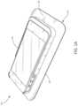
In some embodiments, theelectronic device 104 may include any electronic device including the RF power converter components described herein. For example, the electronic device may be any of a variety of portable technologies, such as a tablet, laptop, cell phone, PDA, wearable device, such as smart watches, fitness devices, headsets, or any other portable, mobile, or other electronic device technology that is capable of being recharged or operated utilizing the principles described herein.
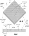
In some embodiments, a chargingsurface 102 may include a housing defined by a plurality ofsidewalls 106, atop surface 108, and a bottom surface (not shown). Thetop surface 108 extends over the bottom surface. Thesidewalls 106 span between thetop surface 108 and the bottom surface. In some embodiments, the housing is formed of plastic, but alternatively or additionally can be formed of other material(s), such as wood, metal, rubber, glass, or other material that is capable of providing for the functionality described herein. As illustrated in FIG.1A, the chargingsurface 102 has a shape of a cuboid, but other two-dimensional or three-dimensional shapes are possible, such as a cube, a sphere, a hemisphere, a dome, a cone, a pyramid, or any other polygonal or non-polygonal shape, whether having an open-shape or a closed-shape. In some embodiments, the housing is waterproof or water-resistant. The chargingsurface 102 may be stiff or flexible and optionally include a non-skid bottom surface to resist movement when placed on a desktop or tabletop. Similarly, thetop surface 108 may be or include non-skid region(s) (e.g., strips) (not shown) or be entirely non-skid to resist motion between thesurface 108 and an electronic device. Still yet, a bracket or other guide may be mounted to thetop surface 108 to assist a user with positioning of an electronic device. The housing may contain various components of the chargingsurface 102, which are described in greater detail herein. Note, the charging surface may be made of heat-conductive material (e.g., aluminum nitride) to absorb heat from the receiver device. Moreover, the entire coupling surface may be made of high-DK (i.e., with high dielectric permittivity) plastics/ceramics that may also be used to mold the unit cells to form the surface.
As described in greater detail below, the chargingsurface 102 may include a plurality of unit cell antennas formed, at least partially, from a substrate material. The substrate may include a metamaterial (i.e., an artificial material being made using small, compared to a wavelength of a signal being transmitted, elements such as patches, dipoles or slots), such as FR4, Rogers, ceramic, or any other material known in the art. The unit cells are designed to retain the RF energy signal used to charge theelectronic device 104 prior to theelectronic device 104 being placed on the chargingsurface 102. That is, when there is no antenna of theelectronic device 104 positioned within the near-field distance, or an antenna of theelectronic device 104 is not tuned or otherwise configured to receive the RF energy signal, the unit cells do not leak or have minimal leakage of the RF energy signal. However, the unit cells are adaptably configured to allow the RF energy signal to leak from the unit cells to an antenna of theelectronic device 104 when the receive antenna is positioned within the near-field distance from the unit cell, and is tuned to the frequency of the RF energy signal (or is otherwise configured to receive the RF energy signal). In the present disclosure, one embodiment of an antenna is considered “tuned” to a particular frequency when leakage of an RF energy signal from the chargingsurface 102 with metamaterial occurs. One or more surfaces of the unit cell may be formed using metamaterial. For example, a ground plane, antenna patch, and/or both may be formed of metamaterial depending on design criteria.
In configuring the unit cells of the chargingsurface 102, the unit cells may be periodically spaced and sized such that a frequency signal that is generated and propagating within a substrate of the unit cells may be substantially retained within the chargingsurface 102 prior to theelectronic device 104 being placed within the near-field of the chargingsurface 102. That is, when an antenna of theelectronic device 104 is place in the near-field of the chargingsurface 102, a change in the boundary conditions of the charging surface results due to capacitance and inductance electrical characteristics being introduced by the electronic device at the surface of the unit cells (seeFIGS.4A and4B ).
The surface may be designed so that electromagnetic tuning results to enable leakage at the particular unit cell(s) that are within the near-field distance of the antenna(s) of the chargingsurface 102. When “tuned” properly, an RF energy signal is retained within a substrate of the unit cells of the chargingsurface 102 and no or minimal leakage occurs. The RF energy signal, when no antenna is in the near-field of the chargingsurface 102, reflects from the surface of the chargingsurface 102, such that no or minimal leakage occurs. And, when “tuned” properly, as when an antenna of theelectronic device 104 is within the near-field of the chargingsurface 102, the surface characteristics of the chargingsurface 102 change and the signals may become aligned with slot dipoles or other feature of the unit cell(s) at the location of the antenna of theelectronic device 104 to cause leakage to occur at that location. In the event that a different frequency is to be used, a dimensional change may be made to the unit cells of the chargingsurface 102 to accommodate the different frequency to avoid leakage. As an example, if higher frequencies are used, smaller unit cells need to be included to provide similar performance.
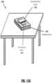
With regard toFIG.1B , an illustration of an illustrative table110 inclusive of asurface 112 on which anelectronic device 114 is positioned is shown. Thesurface 112 may fully or partially be configured to operate as a charging surface utilizing the same or similar principles and configuration as the chargingsurface 102. By providing a piece of furniture, for example, inclusive of a charging surface, theelectronic device 114 may be placed on the chargingsurface 112 and theelectronic device 114 will charge independent of a separate charging device or external pad, such as shown inFIG.1A . It should be understood that a wide variety of devices, furniture, and/or structures may be configured to include a charging surface on one or more surface regions of the devices, furniture, and/or structures. It should also be understood that while a horizontal surface is desirable, alternative angled surfaces may be provided, as well.
As shown, anantenna layer 116 provides for the same or similar structure as the chargingsurface 102 such that an RF energy signal may be leaked from the chargingsurface 102 in response to an antenna tuned to the frequency of the RF energy signal being positioned in a near-field distance of the chargingsurface 102. In one embodiment, rather than theentire charging surface 112 being configured to operatively charge an electronic device, a portion of the chargingsurface 112 may be configured to perform the charging functionality, as described herein.
In one embodiment, amicrocontroller 208 may include circuitry for generating and controlling RF transmission using antenna elements204. These RF signals may be produced using anexternal power supply 212 and RF circuitry (not shown) including a local oscillator chip (not shown) using a suitable piezoelectric material, filters, and other components. These RF signals are then connected to the antennas204 and cause an RF energy signal to be present in the unit cells of the chargingsurface 102.Microcontroller 208 may also process information sent by a receiver through its own antenna elements for determining times for generating the RF signals and for causing the appropriate power level to be produced by the resulting RF energy signals. In some embodiments, this may be achieved usingcommunications component 210 configured to cause the RF energy signals to be produced within a desired frequency range, as previously described and as understood in the art. In an alternative configuration, rather than using a local signal generator, a non-local signal generator (i.e., outside the charging surface102) may be utilized.
In some embodiments, a power amplifier (not shown) and gain control circuitry (not shown) may be applied to each antenna204. However, given the number of antennas that may be used in a chargingsurface 102, the use of one or more power amplifiers to amplify an RF signal (an RF signal that is supplied to or generated within the charging surface102) in order to generate an RF energy signal (the signal that is applied to the antennas204) to feed each of the multiple antennas204 provides for reduced circuitry and lower cost. In one specific embodiment, four RF input ports (not shown) may be used to feed the antennas204 of the chargingsurface 102. In designing the chargingsurface 102, a single RF input port or RF generator internal to the chargingsurface 102 may support a certain number or ratio of antennas204.
In one embodiment,communications component 210 may include a standard wireless communication protocol, such as Bluetooth® or ZigBee®. In addition,communications component 210 may be used to transfer other data, such as an identifier for theelectronic device 104 orsurface 102, battery level, location, charge data, or other such data. Other communications components may be possible, which may include radar, infrared cameras, or frequency-sensing devices for sonic triangulation to determine the position of theelectronic device 104.
In one embodiment, in response to the communications component receiving a wireless signal (e.g, Bluetooth® signal) from an electronic device to be charged by the chargingsurface 102, themicrocontroller 208 may be notified using a digital signal214 to responsively cause thecommunications component 210 to generate anRF energy signal 216 to be applied to antennas204. In an alternative embodiment, the communications component may have its own RF circuitry and antenna(s) for receiving wireless signals, and the microcontroller causes RF energy for charging to be applied to the antennas. With such a configuration, an RF port (seeFIGS.5B and6B ) may provide for an electrical conductor to provide for an RF signal to be communicated to thecommunications component 210 for processing and communication to the antennas204. In yet another embodiment, a separate device, such as battery pack, protection case of a mobile device, or any other device that may be used to charge or power an electronic device may include RF circuitry and antenna(s) for receiving wireless signals from the chargingsurface 102.
In one embodiment, a separate antenna (not shown) may be configured to receive RF signals and communicate the received RF signals to thecommunications component 210 for processing and/or directly routing to the antennas204. The use of a separate antenna may enable the chargingsurface 102 to be operated remotely from a far-field transmitter that transmits an RF charging signal to the chargingsurface 102 for charging or powering an electronic device in a near-field manner, as described herein.
Thepower supply 212 may be provided by way of a connection (e.g., a USB or microUSB connection) to a laptop, wall charger, internal battery, external battery, or other power source. Thepower supply 212 may be used to power circuitry on or at the chargingsurface 102.
Atstep 264, an RF antenna of an electronic device may enter a near-field of the charging surface. The near-field may be a range at which the charging surface is capable of leaking the RF energy signal from the surface in response to a capacitance and/or inductance change near the charging surface, as further described herein.
Atstep 266, the RF energy signal may be leaked from the charging surface in response to the RF antenna entering the near-field of the charging surface. As an example, if the amount of RF energy in the RF energy signal that is distributed and being propagated within the substrate of the charging surface is 5 W, then the RF energy signal may automatically be routed to a location (e.g., above one or more unit cells) of the antenna of the electronic device that is within the near-field of the charging surface and leaked therefrom to cause the 5 W to be applied to the antenna entering the near-field of the charging surface. As understood in the art, the amount of charge that results from being in the near-field of the charging surface is based on the amount of coupling between the two antennas. If, for example, a coupling ratio is 1, then there is 0 dB loss. If, for example, the coupling ratio is 0.5, then there is a 3 dB loss.
Atstep 268, when the RF antenna exits from the near-field of the charging surface, the RF energy signal stops being leaked from the charging surface atstep 270. At that time, the RF energy signal again is trapped/stored within the substrate of the charging surface. Alternatively, in one embodiment, the RF signal that is applied to the charging surface to create the RF energy signal is turned off to save power.
Thedevice antennas 304 may include suitable antenna types for operating in frequency bands similar to the bands described above with respect toFIG.2A . In some embodiments, thedevice antennas 304 may include an antenna designed for Wi-Fi data communication with theelectronic device 104, and an antenna designed for wireless data communication associated with telecommunications of theelectronic device 104. Theantennas 304 may be conventional and native to theelectronic device 104 as produced off-the-shelf for consumer usage. In some embodiments, thedevice antennas 304 that operate in the frequency bands as described above serve at least two purposes. One exemplary purpose is to facilitate the data communication with theelectronic device 104 over wireless standards such as Bluetooth or WLAN for communication of user data as well as for communication of data related to the wireless charging function. A second purpose is to receive the RF charging signal from a charging surface and provide this signal to thereceiver component 302. In such embodiments thedevice antennas 304 are serving two functions, and there is no separate dedicated antenna for reception of wireless charging signal.
However, in other embodiments, theelectronic device 104 may include two sets of antennas. One set of one or more antennas to facilitate wireless data communication such as over Bluetooth or WLAN for communication of user data as well as data related to wireless charging operation; a second set of one or more antennas to receive RF wireless charging signals and provide this signal to thereceiver component 302. In this embodiment, one set of antenna(s) is dedicated to the reception of RF charging signal. Note that in this embodiment, use of separate set of antenna(s) allows for the data communication and RF charging to operate on different frequencies if desired.
The charging surface has a certain operating frequency band. Depending on that operating frequency band of an antenna of anelectronic device 104, the antenna of theelectronic device 104 is to be within the operating frequency band of the charging surface so that power transfer within the near-field may be made. As an example, if the RF frequency of the RF energy signal operates within a Wi-Fi frequency band, then antennas for mobile communications will not cause leakage of the RF energy signal due to being outside the frequency band of the charging surface. In one embodiment, a separate device, such as a power pack with an antenna, power converter, and battery, may be configured to operate at a frequency outside the frequency band of conventional mobile communications (e.g., GSM, LTE, etc.). As an example, the charging surface may be configured to operate over an unlicensed frequency band, and a power pack may be configured to also operate over that frequency band so that communications are not impacted when being charged by the charging surface.
In some embodiments, thereceiver component 302 may incorporate antennas (not shown) that are used in lieu of, or in addition to, theelectronic device antennas 304. In such embodiments, suitable antenna types may include patch antennas with heights from about 1/24 inch to about 1 inch and widths from about 1/24 inch to about 1 inch, or any other antenna, such as a dipole antenna, capable of receiving RF energy signals generated by the chargingsurface 102. Alternative dimensions may be utilized, as well, depending on the frequencies being transmitted by the antenna. In any event, regardless of whether theoriginal device antennas 304 or additional antennas incorporated into thereceiver 302 are used, the antennas should be tuned or otherwise be configured to receive the RF energy signal generated by the chargingsurface 102 when placed within a near-field distance from the chargingsurface 102. In some embodiments, thereceiver component 302 may include circuitry for causing an alert signal to indicate that the RF energy signal is received. The alert signal may include, for example, a visual, audio, or physical indication. In an alternative embodiment, rather than using an antenna internal to an electronic device, a separate charging device, such as a “back pack” that may simultaneously operate as a protective case, as an example, for the electronic device (e.g., mobile phone), may include an antenna along with a power conversion electronic device that converts the RF energy signal into a DC power signal.
The switch element(s)305 may be capable of detecting the RF energy signals received at one or more of theantennas 304, and directing the signals to therectifier 306 when the detected signals correspond to a power level that exceeds a threshold. The switch element(s) may be formed from electronics, such as diode(s), transistor(s), or other electronic devices that may be used to determine a power level, absolute or average, that causes the switch element(s)305 to route the signal from a receiver to therectifier 306 for power conversion thereby. For example, in some embodiments, the switch may direct the received RF energy signals to therectifier 306 when the RF energy signal received at theantenna 304 is indicative of a wireless power transfer greater than 10 mW. In other embodiments, the switch may direct the received RF energy signals when they are indicative of a wireless power transfer greater than 25 mW. This switching acts to protect from damaging electronic components, such as a receiver circuit, of theelectronic device 104 by preventing a power surge from being applied thereto. If the threshold power is not reached, the electronic device operates in a conventional manner.
Therectifier 306 may include diodes, resistors, inductors, and/or capacitors to rectify alternating current (AC) voltage generated byantennas 304 to direct current (DC) voltage, as understood in the art. In some embodiments, therectifier 306 and switch305 may be placed as close as is technically possible to theantenna element 304 to minimize losses. After rectifying AC voltage, DC voltage may be regulated and/or conditioned usingpower converter 308.Power converter 308 can be a DC-DC converter, which may help provide a constant voltage output, regardless of input, to an electronic device or, as in this embodiment, to abattery 312. Typical voltage outputs can be from about 0.5 volts to about 10 volts. Other voltage output levels may be utilized, as well.
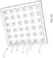
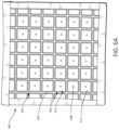
Referring now toFIGS.5A-5D , an example embodiment of anantenna portion 500 of a charging surface is provided, wherein theantenna portion 500 includes a plurality ofunit cells 502 arranged in a matrix formation. Each of theunit cells 502 includes twosubstrate layers top substrate layer 515aof each of theunit cells 502 includes a metal portion504 (e.g., copper) definingapertures 506 positioned at the top of theunit cells 502. Thebottom substrate layer 515bof eachunit cell 502 includes apatch antenna 510 comprising ametal patch 512 having an electrical connection through a via508 to aground plane 514. Theground plane 514 may be a metamaterial. Theground plane 514 is connected to anRF port 505 as shown inFIG.5B for conducting RF signals tounit cells 502.
In some embodiments, thepatch antenna 510 is configured to generate the RF energy signal that radiates within thetop substrate layer 515a. In accordance with the present disclosure, the RF energy signal remains in thetop substrate layer 515auntil the RF energy signal decays or is leaked to an antenna304 (FIG.3 ) of an electronic device positioned on a charging surface.
In some embodiments, the size of theaperture 506 is determined in accordance with the periodic frequency of the RF energy signal such that the RF energy signal does not leak from theaperture 506 in theunit cells 502 unless an antenna tuned to the frequency of the RF energy signal is positioned in a near-field distance (e.g., less than about 4 mm) from at least one of theunit cells 502.
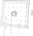
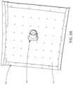
Referring now toFIGS.6A-6D , an example embodiment of anantenna portion 600 of a charging surface is provided, where theantenna portion 600 is composed of a plurality ofunit cells 602 arranged in a matrix formation. Each of theunit cells 602 includes onesubstrate layer 615 having a metal portion604 (e.g., copper) defining anaperture 606 positioned at the top of theunit cells 602. Theunit cells 602 also include apatch antenna 610 formed by ametal patch 612 having an electrical connection through a via608 to aground plane 614. Theground plane 614 may be physically and electrically connected to anRF port 605, as shown inFIG.6B . TheRF port 605 may be used to provide an RF energy signal from an RF energy signal generator to be applied to each of theunit cells 602, and theground plane 614 may be electrically connected to a ground portion of theRF port 605.
In the embodiment illustrated inFIGS.6A-6D , thepatch antenna 610 is positioned within theunit cell 602 such that theaperture 606 is formed around a perimeter of themetal patch 612. In some embodiments, thepatch antenna 610 is configured to propagate the RF energy signal from the top surface of thesubstrate layer 615. In accordance with the present disclosure, the RF energy signal remains at or near the top surface of thesubstrate layer 615 until the RF energy signal decays or is received by theelectronic device antenna 304.
In some embodiments, the size of theaperture 606 is determined in accordance with the periodic frequency of the RF energy signal generated by thepatch antenna 610 such that the RF energy signal does not or has minimal leakage from theaperture 606 of theunit cells 602 unless an antenna tuned to the frequency of the RF energy signal is positioned in a near-field distance from at least one of theunit cells 602. Theaperture 606 may be altered in dimension depending on frequency of the RF energy signal so as to be properly tuned for preventing leakage of the RF energy signal when no electronic device is positioned in the near-field. It should be understood that a number of layers of the unit cell may vary depending on the application, where different number of layers may provide different responses from the unit cells to provide different harmonic responses (e.g., higher or shifted harmonic frequencies for different wireless powering applications).
Resonance
A resonant coupler may be formed when a device to be charged itself enables transmission of power and operates as part of a charging system. For example, a mobile telephone having a metallic case may be utilized to complete a charging device, as further described inFIGS.7A and8A-8C . The charging system may work in two different stages. A first stage may provide for a field being fed through a feeding point (e.g., slot on a ground plane) into a first cavity and getting trapped in the structure of the first cavity. The first cavity may include a number of touch/leak points that are activated when being touched by or proximately close to an electronic device with a metal case. A second stage may operate when the electronic device is placed on the surface at a touch point so that energy leaks out of the second cavity formed in part by the electronic device on top of the charging surface.
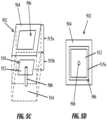
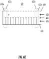
In the embodiment illustrated inFIGS.7A and8A-8C , theelectronic device 104 includes aback surface 701 that is generally formed ofmetallic surfaces gaps gaps antennas 304 such that theantennas 304 may receive signals entering through thegaps metallic surfaces FIG.8A , such that theRF energy signal 802 generated by the chargingsurface 700 traverses or resonates within acavity 706 formed between atop surface 708 of the chargingsurface 700 and one or more of themetallic surfaces gaps RF energy signal 802 traverses or resonates between themetal surface 702b, for example, and top surface of the chargingsurface 700 as a trapped wave in the cavity706 (seeFIG.8A ,RF energy signal 802 reflecting between the two surfaces). Thegaps surface 700, and more specifically, one or more unit cells of the chargingsurface 700, so that theRF energy signal 802 can traverse thecavity 706 to reach one of thegaps RF energy signal 802 reaches thegap 704a, theRF energy signal 802 enters through thegap 704aand is received by thedevice antenna 304.
More particularly, as shown inFIGS.8B and8C , the chargingsurface 700 is shown to include acover 802 within which afirst cavity 804aand asecond cavity 804b(collectively804) are formed by aground plane 806 that separates the two cavities804. The ground plane may be formed of metamaterial, as described herein. The chargingsurface 700 may also include one ormore touch points 810 from which an RF energy signal emanates. In operation, a first stage may provide for an RF energy signal being fed through a feeding point (e.g., slot on a ground plane) into thefirst cavity 804aand gets trapped in the structure of thefirst cavity 804a. Thefirst cavity 804amay include a number of touch/leak points 810 that are activated when being touched by or proximately close to an electronic device with a metal case. A second stage may operate when the electronic device is placed on thecover 802 at at least one of the touch points810 so that energy leaks out of thesecond cavity 804bformed in part by the electronic device on top of thecover 802 of the chargingsurface 700. Because only afew touch points 810 are utilized in this chargingsurface 700, fewer power amplifiers are needed to supply RF energy signals, thereby costing less than having many more touch points. In one embodiment, fourtouch points 810 may be utilized. However, it should be understood that the number of touch points may vary depending on the size of the area provided by the chargingsurface 700. If a large area (e.g., desk) is provided, thenmore touch points 810 are provided. If a smaller area (e.g., pad) is provided, then fewer touch points810 are provided.
In some embodiments, such as that shown inFIGS.7A and8A , themetallic surfaces top surface 708 of the chargingsurface 700. Although theRF energy signal 802 is represented inFIG.8A as having a triangle waveform reflection, it should be appreciated that theRF energy signal 802 may be reflected in other patterns, as understood in the art. As used herein, “traverses” refers to the RF energy signal travelling along or through a space or cavity by reflecting off of surfaces.
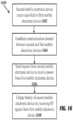
Referring now toFIG.9 , an example method is shown in flow diagram900 for charging theelectronic device 104 with the chargingsurface 700 in accordance with an embodiment of the present disclosure. In the embodiment illustrated inFIG.9 , the chargingsurface 102 communicates with theelectronic device 104 viarespective communication components step 902, the chargingsurface communication component 210 receives, from the electronicdevice communication component 310, a signal indicative of a request to charge theelectronic device 104. In some embodiments, this signal may include, for example, an identification of theelectronic device 104, a battery level, power requirements of theelectronic device 104, or other information. For example, in some instances, theelectronic device 104 may be a device having a lower power requirement, such as, for example, a smart-watch or other wearable technology. In order to avoid receiving a large power surge that would damage the smart-watch, the charge request could include a power limit, such as, 0.5 W. Alternative power levels may be utilized, as well. Similarly, theelectronic device 104 may have a larger power requirement. In such cases, the charge request could include the larger power requirement, such as 5 W, for charging theelectronic device 104.
Rather than receiving an active charge request, the charging surface may receive or sense any wireless or radiation signal from an electronic device that indicates that an electronic device is proximate to the charging surface, including but not limited to the presence or absence of reflection of an RF energy signal transmitted by the charging surface. Any receiver or sensor may be utilized to sense such a signal from an electronic device. In an alternative embodiment, a proximity switch or pressure switch may be utilized to detect that an electronic device is proximate to or positioned on the charging surface. Still yet, a magnetic switch or light switch may be utilized.
Atstep 904, themicrocontroller 208 initiates generation of an RF energy signal in accordance with the data provided in the charge request. For example, if the charge request indicates the power requirements of theelectronic device 104, then themicrocontroller 208 causes the RF energy signal to be generated such that the power transmitted to theelectronic device 104 complies with the power requirements communicated in the charge request. In accordance with the above example of a smart-watch, themicrocontroller 208 may cause the chargingsurface 700 to generate an RF energy signal capable of providing wireless power transfer of 0.5 W to the smart-watch. In one embodiment, if an electronic device is sensed, then an RF energy signal may be generated.
As discussed herein, the RF energy signal is generated in the unit cells of the chargingsurface 700, and substantially remains in the unit cells until the RF energy signal decays or is leaked. When anantenna 304 tuned to the frequency of the RF energy signal is placed within a near-field distance from one or more of the unit cells, those unit cell(s) allow the RF energy signal to leak to theantenna 304 atstep 906.
Asstep 908, the leaked RF energy signal is received at the antenna(s)304 tuned to the frequency of the RF energy signal and placed within the near-field distance from the unit cell(s).
At step910, the received RF energy signal is converted to a power signal to charge thebattery 312 of theelectronic device 104. This step may include detecting the RF energy signal received at theantenna 304, activating theswitch mechanism 305 when the RF energy signal is indicative of a power signal greater than the threshold value (e.g., 10 mW) rectifying the signal via therectifier 306, and converting the rectified signal to a DC power signal via theconverter 308. The power signal is then used to charge or operate theelectronic device battery 312 at step912.
Although it is not illustrated in the flow diagram900, thecommunications component 310 may, in some embodiments, transmit a signal to the chargingsurface 700 to request that the charging be suspended or discontinued. This may happen, for example, if thebattery 312 of theelectronic device 104 is completely charged or reaches a desired charge level, theelectronic device 104 is being turned off, thecommunications component 310 is being turned off or moved out of communication range with thecommunications component 210, or for other reasons. In another embodiment, in the event that the electronic device is no longer being sensed, electronically, physically or otherwise depending on the sensor being utilized, then thecommunications component 210 may be turned off.
Referring now toFIG.10 , an example method is shown in flow diagram1000 for sensing the presence of and charging theelectronic device 104 with the chargingsurface 700 in accordance with an embodiment of the present disclosure. In the embodiment illustrated inFIG.10 , theelectronic device 104 does not communicate with the chargingsurface 102 viarespective communication components electronic device 104 is turned off, has a drained battery, or is otherwise unable to communicate with the chargingsurface 700. Thus, in the present embodiment, the chargingsurface 700 operates in a manner so as to avoid flooding an undetectedelectronic device 104 with excessive power. This is the manner that a receiver with a dead battery, and hence no ability to communicate with the transmitter, may be charged.
Atstep 1002, the chargingsurface 700 generates a low-power RF energy signal, which is an RF energy signal capable of providing wireless, low-power transmission to anelectronic device 104. Specifically, themicrocontroller 208 initiates generation of the low-power RF energy signal such that the power capable of being transmitted via the low-power RF energy signal is “low-power.” For example, in some embodiments, low-power is 1 W. Alternative power levels may be utilized, as well. In some embodiments, detecting that an electronic device is positioned within a near-field distance of the charging surface may be accomplished by activating the unit cell patch antennas204 with a 1% duty cycle.
In accordance with the present disclosure, the low-power RF energy signal is generated in the unit cells of the chargingsurface 700, and remains in the unit cells until the low-power RF energy signal decays or is leaked. When an antenna304 (of a receiver) tuned to the frequency of the low-power RF energy signal is placed within a near-field distance from one or more of the unit cells, those unit cells allow the RF energy signal to leak to theantenna 304 atstep 1004.
Atstep 1006, themicrocontroller 208 may sense the low-power RF energy signal present in the unit cells. For example, in some embodiments, themicrocontroller 208 may include sensing circuitry, such as, an RF coupler capable of detecting a “reflection” of the low-power RF energy signal, where the reflection is representative of, for example, approximately 10% of the low-power RF energy signal present in the unit cells. Themicrocontroller 208 may, therefore, calculate the low-power RF energy signal present in the unit cells based on the reflected value sensed by themicrocontroller 208. Although the sensing performed atstep 1006 is illustrated in a sequential order inFIG.10 , it should be appreciated that this step may be performed in any order or repeated continuously in parallel with the processes performed in the flow diagram1000. The low-power RF energy signal may be generated periodically or aperiodically in a pulsed or other manner to determine if an electronic device is present, as indicated in the diagram1000.
Once themicrocontroller 208 senses the low-power RF energy signal present in the unit cells, the sensed low-power RF energy is compared to a threshold value atstep 1008 to determine whether to generate a subsequent low-power RF energy signal within the unit cells. Instances in which the sensed low-power RF energy signal is less than the threshold value are indicative of a situation in which the low-power RF energy signal has either decayed or leaked to an antenna tuned to the frequency of the low-power RF energy signal and positioned within a near-field distance from one or more of the unit cells. Thus, if the sensed low-power RF energy signal is less than the threshold, it is presumed the low-power RF energy signal has either leaked or decayed, so the process returns to step1002 and themicrocontroller 208 activates the antennas204 to generate a subsequent low-power RF energy signal. Otherwise, when the reflection is above the threshold, the low-power RF energy signal remains in the substrate and subsequent RF signals are not generated so that the unit cells of the chargingsurface 700 do not continue to build up energy. Accordingly, the process returns to step1006, and themicrocontroller 208 continues to sense the low-power RF energy signal present in the unit cells.
The method illustrated inFIG.10 is indicative of a situation in which nocommunication component 310 is communicating with the chargingsurface 700. For example, thebattery 312 of theelectronic device 104 may be too depleted to activate thecommunication component 310. However, once thebattery 312 has sufficient charge, theelectronic device 104 may, in some embodiments, activate thecommunication component 310. At that time, thecommunication component 310 may initiate communication with thecommunication component 210 of the chargingsurface 700, and the chargingsurface 700 may switch to the charging method illustrated inFIG.9 and described above.
Harmonic Filter
In conventional power-transmission systems, various electronic elements that form the system are often lumped together, and losses experienced by each lumped element are compounded such that the system, as a whole, experiences a larger loss than each of the elements individually. For example, if a system has an antenna that is 90% efficient lumped with an amplifier that is 90% efficient, then the combined efficiency of a system comprising these two elements is approximately 81%. As more elements are added, the overall efficiency of the system is further reduced. Accordingly, in order to increase the efficiency of the disclosed charging surface, some embodiments of the charging surface may include filter elements such as, a harmonic filter, to reduce the radiated energy in frequencies other than the intended wireless charging signal, and specifically to reduce the energy in the harmonics of the intended wireless charging signal. A harmonic filter may, for example, attenuate these frequency components by 40 dB to 70 dB
It should be appreciated that theharmonic filter element 1104 included in eachunit cell 1102 may be a discrete filter element, or it may be a portion of a larger, single harmonic filter element spanning the top surfaces ofmultiple unit cells 1102 forming the chargingsurface 102. Thus, the chargingsurface 102 includes, in such embodiments, aharmonic filter element 1104 placed over theunit cells 1102 such that the chargingsurface 102 includes a harmonic filter positioned over a matrix (or array) of transmit antennas (e.g., patch antennas610).
In the embodiment illustrated inFIGS.11A and11B , each of theunit cells 1102 includes asingle substrate layer 615, and theharmonic filter element 1104 present in each of theunit cells 1102 comprises a single harmonic filter element spanning the entire top surface area of theunit cells 1102. In other embodiments, however, theharmonic filter element 1104 may include multiple harmonic filter elements, where one of the multiple harmonic filter elements are disposed on a top surface of one of the elements forming theunit cells 1102. It should be understood that the unit cell with the harmonic rejection filter may be formed by a more complex unit cell, such as a unit cell that includes more layers and features within the unit cell. For example, this latter embodiment could be represented by aharmonic filter element 1104 placed on the top surface area of thepatch antenna 610, aharmonic filter element 1104 placed on the top surface area of themetal portion 604, and no harmonic filter element covering theaperture 606.
In some embodiments, theharmonic filter element 1104 is formed of two or more screen layers, wherein each layer includes a screen to filter out specific harmonics of the intended wireless charging signal. Theharmonic filter 1104 acts to filter the RF energy signal generated by thepatch antenna 610 such that the RF energy signal operates at a particular frequency (also referred to herein as a center frequency). As a result of theharmonic filter element 1104 being a passive mechanical device, loss in signal power is reduced as compared with an electronic filter.
In the embodiment illustrated inFIGS.12A and12B , theunit cells 1202 include atop substrate layer 515aand abottom substrate layer 515b, and theharmonic filter element 1204 present in thetop substrate layer 515aof each of theunit cells 1202 comprises a single harmonic filter element spanning the entire area of thetop substrate layer 515aof theunit cells 1202. In other embodiments, however, theharmonic filter element 1204 may span only a portion of thetop substrate layer 515asuch that theharmonic filter element 1204 is disposed above only thepatch antenna 510, which is located in thebottom substrate layer 515b.
In some embodiments, theharmonic filter element 1204 is formed of two or more screen layers, wherein each layer includes a screen to filter out specific harmonics of the intended wireless charging signal. Theharmonic filter 1204 acts to filter the RF energy signal generated by thepatch antenna 510 such that the RF energy signal operates at a particular frequency (also referred to herein as a center frequency). As a result of theharmonic filter element 1204 being a passive mechanical device, loss in signal power is reduced as compared with an electronic filter.
Receiver Device Stacking
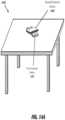
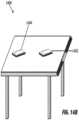
As shown inFIG.13A , in some embodiments, theelectronic devices surface 1306 to thefirst device 1302, and then from thefirst device 1302 to thesecond device 1304. As shown inFIG.13B , thefirst device 1302 may receive power from the chargingsurface 1306 using near-field power transfer techniques, and then thefirst device 1302 may transfer power to thesecond device 1304 using far-field power transfer techniques.
Near-field RF power transmission techniques may include a transmitter-side charging surface 1306 comprising a number of physical layers, such as a substrate or cavity for trapping RF energy and a top surface on which to place anelectronic device electronic device charging surface 1306 only when anelectronic device electronic device surface 1306 until some physical condition is satisfied by a receiver-sideelectronic device electronic device 1302 would need to be within one millimeter before the RF energy will be leaked from the substrate or cavity layer of thecharging surface 1306.
Far-field RF power transmission techniques may include circumstances where a transmit-side device comprises an array of one or more antennas (not shown) configured to transmit RF power waves over some distance, which may range from less than an inch to more than fifty feet. In proximity far-field power transmission, the transmit-side device may be configured to transmit the power waves within a limited distance, such as less than twelve inches. This may be limited in any number of ways, such as requiring a receiver-side device to enter a proximity threshold from the transmit-side device before the transmit-side device will transmit power waves, or limiting the effective range for the power waves to deliver power. In some implementations, a transmit-side device functioning as a proximity transmitter may transmit the power waves to converge at or near a particular location so that the power waves generate constructive interference patterns. A receiver-side device may comprise an antenna and circuitry capable of receiving the resulting energy at the constructive interference patterns, and may then convert the energy to useable alternating current (AC) or direct current (DC) power for an electronic device coupled to the receiver device or comprising the receiver device.
A chargingsurface 1306 may generate one or more RF energy signals for wireless power transmission that are trapped in a substrate or cavity beneath a top surface of thecharging surface 1306. The trapped RF energy may be leaked through the top surface and received by thefirst device 1302 when an appropriately tuned antenna of thefirst device 1302 is positioned within a near-field distance (e.g., less than approximately 10 mm) from the chargingsurface 1306. The appropriately tuned antenna of thefirst device 1302 may thus cause the RF signals trapped within the chargingsurface 1306 to be leaked or emitted through the chargingsurface 1306 to the antenna of thefirst device 1302. The received RF energy signals are then converted to a power signal by a power conversion circuit (e.g., rectifier circuit) for providing power to or charging a battery of thefirst device 1302. In the exemplary embodiments shown inFIGS.13A and13B, the chargingsurface 1306 may be shown as a box-shaped device, but it should be understood that the chargingsurface 1306 may have any form-factor, configuration, and/or shape. In some embodiments, the total power output by the chargingsurface 1306 is less than or equal to 1 Watt to conform to Federal Communications Commission (FCC) regulations part 15 (low-power, non-licensed transmitters).
Similar to the manner in which thecharging surface 1306 may function as a transmitter-side device in relation to the firstelectronic device 1302, the firstelectronic device 1302 may be configured to likewise function as a transmitter-side device in relation to a secondelectronic device 1304.
As shown inFIG.13A , in some embodiments, thefirst device 1302 may comprise components for a near field RF charging surface, similar to thecharging surface 1306, allowing RF energy signals to be trapped beneath a surface layer of thefirst device 1302 until an appropriately tuned antenna of asecond device 1304 causes the RF energy to be leaked into the antenna of thesecond device 1304.
Additionally or alternatively, as shown inFIG.13B , in some implementations, thefirst device 1302 may be configured to function as a far-field proximity transmitter comprising an array of one or more antennas configured to transmit one or more power waves to an antenna of the secondelectronic device 1304.
In some embodiments, thefirst device 1302 may include a communications component (not shown) to effectuate wireless and/or wired communications to and from other devices, such as thesecond device 1304. In some cases, a communications component may be an embedded component of thefirst device 1302; and, in some cases, the communications component may be attached to thefirst device 1302 through any wired or wireless communications medium. The communications component may comprise electromechanical components (e.g., processor, antenna) that allow the communications component to communicate communications signals containing various types of data and messages with other devices, such as thesecond device 1304. These communications signals may represent a distinct channel for hosting communications where data may be communicated using any number of wired or wireless protocols and associated hardware and software technology. The communications component may operate based on any number of communication protocols, such as Bluetooth®, Wireless Fidelity (Wi-Fi), Near-Field Communications (NFC), ZigBee, and others. However, it should be appreciated that the communication component is not limited to radio-frequency based technologies, but may include radar, infrared, and sound devices for sonic triangulation of other devices, like thesecond device 1304.
In operation, the communications component of thefirst device 1302 may receive communications signals from the secondmobile device 1304, where the communications signals contain data that includes a request to receive power from thefirst device 1302. Additionally or alternatively, the firstelectronic device 1302 may receive one or more wireless broadcasted messages from thesecond device 1304, thereby allowing the firstelectronic device 1302 to detect the presence of the secondelectronic device 1304 and begin sending power to the secondelectronic device 1304, or to begin flooding a substrate or cavity layer with RF energy. Such request messages may also include data related to the type of device, battery details of the device, such as battery type and present battery charge, and present location of the device. In some implementations, the firstelectronic device 1302 may use the data contained within the messages to determine various operational parameters for transmitting or otherwise transferring RF energy to thesecond device 1304, which thesecond device 1304 may capture and convert the RF energy into useable alternating current (AC) or direct current (DC) electricity.
For example, when thefirst device 1302 functions as a near-field charging surface, thefirst device 1302 may be configured to send power (e.g., engage, turn on, wake up) to a near-field charging surface within thefirst device 1302 when the communications component of the firstelectronic device 1302 receives a communications signal having a threshold signal strength indicating that thesecond device 1304 is within a threshold distance.
As another example, where thefirst device 1302 functions as a far-field proximity transmitter, thefirst device 1302 may use the communications signal receive data from thesecond device 1304 that may be used by thefirst device 1302 to identify the location ofsecond device 1304 and to determine whether the secondelectronic device 1304 is within a threshold distance from thefirst device 1304.
Similarly, a communications component of thesecond device 1304 may use a communications signal to communicate data that may be used to, for example, send or otherwise broadcast a message to thefirst device 1302 requesting thefirst device 1302 to transfer power; the messages may also include, for example, battery power information, data indicating present location, data information about the user of thesecond device 1304, information about thesecond device 1304 to be charged, indicate the effectiveness of the power being received, and a request to stop sending the power, as well as other types of useful data. Non-limiting examples of the various types of information that may be included in communications signals may also include a beacon message, a device identifier (device ID) forfirst device 1302, a user identifier (user ID) for thefirst device 1302, the battery level for thesecond device 1304, thesecond device 1304 location, and other such information.
In some cases, when thesecond device 1304 enters a near-field distance of thefirst device 1302 in which the RF energy can be leaked and emitted from thefirst device 1302 into thesecond device 1304, the devices may establish a communications channel according to the wireless or wired communications protocol (e.g. Bluetooth®) employed by the respective communications components of therespective devices second device 1304 may establish a communication channel with thefirst device 1302 upon entering the effective communications distance of thefirst device 1302 of the wired or wireless communications protocols employed by the communications components. A near-field distance may be defined as a minimum distance between a transmitter-side device (e.g., charging surface1306) and a receiver-side device (e.g., first electronic device1302) that would cause the transmitter-side device to leak and transfer trapped RF wave signals into the appropriately tuned receiver-side device. This near-field distance may range from direct contact to about 10 millimeters. In some cases, a proximate far-field distance may be the minimum distance between a transmitter-side device to transmit one or more power waves to a receiver-side device, which may range up to about 12 inches. In an alternative embodiment, any far-field distance can be used.
The antennas of thesecond device 1304 may capture energy from the RF signals leaked or emitted from thefirst device 1302 or from the power waves transmitted from thefirst device 1302. After RF signals are received from the power waves or from the leakage, from either thecharging surface 1306 or thefirst device 1302, circuitry and other components (e.g., integrated circuits, amplifiers, rectifiers, voltage conditioner) of both the first andsecond devices electronic device second device 1304 may convert the electrical energy from AC to DC form, usable by thesecond device 1304. Other types of conditioning may be applied as well, in addition or as an alternative to, conversion from AC to DC. For example, a voltage conditioning circuit, such as a voltage regulator, may increase or decrease the voltage of the electrical energy as required by thesecond device 1304.
In an alternate embodiment, thefirst device 1302 may also send a charging request to thesecond device 1304. The charging request may include data related to user of thefirst device 1302, details of thefirst device 1302, battery charge of thefirst device 1304, current location of thefirst device 1302. Upon receiving a charging request, thesecond device 1304 may accept or decline the request. Thesecond device 1304 may also request additional details related to but not limited to user of thefirst device 1302, details of thefirst device 1302, battery charge of thefirst device 1302, current location of thefirst device 1302, if such details were not present with the request. On accepting the request, thesecond device 1304 may determine the location of thefirst device 1302. Thesecond device 1304 may use one or more technologies such as sensor detection, heat-mapping detection, and others to determine the location of thefirst device 1302. Once the location of thefirst device 1302 is determined, then thesecond device 1304 may transmit RF signals to thefirst device 1302, which may be captured by antennas and/or circuitry of thefirst device 1302 to charge a battery of thefirst device 1302.
Referring again toFIG.13A , in some embodiments, thefirst device 1302 and thesecond device 1304 may be placed on top of each other to transfer power from one or another, with or without the presence of chargingsurface 1306. In another embodiment, thefirst device 1302 and thesecond device 1304 may be on same plane and proximate to each other to transfer power from one or another device as depicted inFIG.13B . It will be appreciated by a person with ordinarily skill in the art that the power transfer between thefirst device 1302 and thesecond device 1304 will occur when the devices are in near-field distances from each other irrespective of their placement with respect to each other.
In an embodiment, thefirst device 1302 may receive power from the chargingsurface 1306, and at the same time transfer the power to thesecond device 1304 in its near-field. In another embodiment, thefirst device 1302 may receive power from any suitable source of receiving power (for example, far-field antennas) and at the same time transfer the power to thesecond device 1304 within a near-field distance. In yet another embodiment, thefirst device 1302 and thesecond device 1304 may transfer power to a third device in their near-field. In yet another embodiment, each of thefirst device 1302 and thesecond device 1304 independently or collectively transfer power to two or more devices in their near-field.
As shown inFIG.14A , in some embodiments, theelectronic devices first device 1402 to thesecond device 1404. As shown inFIG.14B , thefirst device 1402 may transfer power to thesecond device 1304 using far-field power transfer techniques.
An antenna of a firstelectronic device 1402 may generate one or more RF energy signals for wireless power transmission. The one or more RF energy signals may be received by thesecond device 1404 when an appropriately tuned antenna of thesecond device 1404 is positioned within a near-field distance (e.g., less than approximately 10 mm) from antenna of the firstelectronic device 1402. The appropriately tuned antenna of thesecond device 1404 may thus cause the RF signals to be emitted through the firstelectronic device 1402 to the antenna of thesecond device 1404. The received RF energy signals are then converted to a power signal by a power conversion circuit (e.g., rectifier circuit) for providing power to or charging a battery of thesecond device 1404. In the exemplary embodiments, the total power output by the firstelectronic device 1402 is less than or equal to 1 Watt to conform to Federal Communications Commission (FCC) regulations part 15 (low-power, non-licensed transmitters).
As shown inFIG.14A , in some embodiments, thefirst device 1402 may comprise components for a near field RF charging surface allowing RF energy signals to be trapped beneath a metamaterial surface layer of thefirst device 1402 until an appropriately tuned antenna of asecond device 1404 causes the RF energy to be leaked into the antenna of thesecond device 1404.
Additionally or alternatively, as shown inFIG.14B , in some implementations, thefirst device 1402 may be configured to function as a far-field proximity transmitter comprising an array of one or more antennas configured to transmit one or more power waves to an antenna of the secondelectronic device 1404.
In some embodiments, thefirst device 1402 may include a communications component (not shown) to effectuate wireless and/or wired communications to and from other devices, such as thesecond device 1404. In some cases, a communications component may be an embedded component of thefirst device 1402; and, in some cases, the communications component may be attached to thefirst device 1402 through any wired or wireless communications medium. The communications component may comprise electromechanical components (e.g., processor, antenna) that allow the communications component to communicate communications signals containing various types of data and messages with other devices, such as thesecond device 1404. These communications signals may represent a distinct channel for hosting communications where data may be communicated using any number of wired or wireless protocols and associated hardware and software technology. The communications component may operate based on any number of communication protocols, such as Bluetooth®, Wireless Fidelity (Wi-Fi), Near-Field Communications (NFC), ZigBee, and others. However, it should be appreciated that the communication component is not limited to radio-frequency based technologies, but may include radar, infrared, and sound devices for sonic triangulation of other devices, like thesecond device 1404.
In operation, the communications component of thefirst device 1402 may receive communications signals from the secondmobile device 1404, where the communications signals contain data that includes a request to receive power from thefirst device 1402. Additionally or alternatively, the firstelectronic device 1402 may receive one or more wireless broadcasted messages from thesecond device 1404, thereby allowing the firstelectronic device 1302 to detect the presence of the secondelectronic device 1404 and begin sending power to the secondelectronic device 1404, or to begin flooding a substrate or cavity layer with RF energy. Such request messages may also include data related to the type of device, battery details of the device, such as battery type and present battery charge, and present location of the device. In some implementations, the firstelectronic device 1402 may use the data contained within the messages to determine various operational parameters for transmitting or otherwise transferring RF energy to thesecond device 1404, which thesecond device 1404 may capture and convert the RF energy into useable alternating current (AC) or direct current (DC) electricity.
For example, when thefirst device 1402 functions as a near-field charging surface, thefirst device 1402 may be configured to send power (e.g., engage, turn on, wake up) to a near-field charging surface within thefirst device 1402 when the communications component of the firstelectronic device 1402 receives a communications signal having a threshold signal strength indicating that thesecond device 1404 is within a threshold distance.
As another example, where thefirst device 1402 functions as a far-field proximity transmitter, thefirst device 1402 may use the communications signal receive data from thesecond device 1404 that may be used by thefirst device 1402 to identify the location ofsecond device 1404 and to determine whether the secondelectronic device 1404 is within a threshold distance from thefirst device 1404.
Similarly, a communications component of thesecond device 1404 may use a communications signal to communicate data that may be used to, for example, send or otherwise broadcast a message to thefirst device 1402 requesting thefirst device 1402 to transfer power; the messages may also include, for example, battery power information, data indicating present location, data information about the user of thesecond device 1404, information about thesecond device 1404 to be charged, indicate the effectiveness of the power being received, and a request to stop sending the power, as well as other types of useful data. Non-limiting examples of the various types of information that may be included in communications signals may also include a beacon message, a device identifier (device ID) forfirst device 1402, a user identifier (user ID) for thefirst device 1402, the battery level for thesecond device 1404, thesecond device 1404 location, and other such information.
In some cases, when thesecond device 1404 enters a near-field distance of thefirst device 1402 in which the RF energy can be leaked and emitted from thefirst device 1402 into thesecond device 1404, the devices may establish a communications channel according to the wireless or wired communications protocol (e.g. Bluetooth®) employed by the respective communications components of therespective devices second device 1404 may establish a communication channel with thefirst device 1402 upon entering the effective communications distance of thefirst device 1402 of the wired or wireless communications protocols employed by the communications components. A near-field distance may be defined as a minimum distance between a transmitter-side device (e.g., first electronic device1402) and a receiver-side device (e.g., second electronic device1404) that would cause the transmitter-side device to leak and transfer trapped RF wave signals into the appropriately tuned receiver-side device. This near-field distance may range from direct contact to about 10 millimeters. In some cases, a proximate far-field distance may be the minimum distance between a transmitter-side device to transmit one or more power waves to a receiver-side device, which may range up to about 12 inches. In an alternative embodiment, any far-field distance can be used.
The antennas of thesecond device 1404 may capture energy from the RF signals leaked or emitted from thefirst device 1402 or from the power waves transmitted from thefirst device 1402. After RF signals are received from the power waves or from the leakage, from thefirst device 1302, circuitry and other components (e.g., integrated circuits, amplifiers, rectifiers, voltage conditioner) of both the first andsecond devices electronic device second device 1404 may convert the electrical energy from AC to DC form, usable by thesecond device 1404. Other types of conditioning may be applied as well, in addition or as an alternative to, conversion from AC to DC. For example, a voltage conditioning circuit, such as a voltage regulator, may increase or decrease the voltage of the electrical energy as required by thesecond device 1404.
As shown inFIG.15 , in some embodiments, theelectronic devices case 1506 to thesecond device 1504. Thefirst device 1502 may receive power from the chargingcase 1506 using near-field power transfer techniques, and then thefirst device 1502 may transfer power to thesecond device 1504 using far-field power transfer techniques. Thefirst device 1502 doesn't transmit its own power to thesecond device 1504 but transmits the power received from the chargingcase 1506 to thesecond device 1504. Thesecond device 1504 may also be able to receive the power directly from the chargingcase 1506 using far-field power transfer techniques.
A chargingcase 1506 such as a battery may store RF energy signals for wireless power transmission. The stored RF energy may be leaked through the top surface and received by thefirst device 1502 when an appropriately tuned antenna of thefirst device 1502 is positioned within a near-field distance (e.g., less than approximately 10 mm) from the chargingcase 1502. The appropriately tuned antenna of thefirst device 1502 may thus cause the RF signals stored within the chargingcase 1506 to be leaked or emitted through thecharging case 1506 to the antenna of thefirst device 1502. Thefirst device 1502 is configured to function as a far-field proximity transmitter comprising an array of one or more antennas configured to transmit the received RF signals to an antenna of the secondelectronic device 1504. The RF energy signals received by the secondelectronic device 1504 are then converted to a power signal by a power conversion circuit (e.g., rectifier circuit) for providing power to or charging a battery of thesecond device 1504. In the exemplary embodiments shown inFIG.15 , the chargingcase 1502 may be shown as a box-shaped battery device, but it should be understood that thecharging case 1502 may have any size, form-factor, configuration, and/or shape. In some embodiments, the total power output by the chargingcase 1502 is less than or equal to 1 Watt to conform to Federal Communications Commission (FCC) regulations part 15 (low-power, non-licensed transmitters).
In some embodiments, thesecond device 1504 may include a communications component (not shown) to effectuate wireless and/or wired communications to and from other devices, such as thecharging case 1502 and/or thefirst device 1502. In some cases, a communications component may be an embedded component of thesecond device 1504; and, in some cases, the communications component may be attached to thefirst device 1504 through any wired or wireless communications medium.
The communications component of thesecond device 1504 may use a communications signal to communicate data that may be used to, for example, send or otherwise broadcast a message to thefirst device 1502 requesting thefirst device 1502 to transfer power; the messages may also include, for example, battery power information, data indicating present location, data information about the user of thesecond device 1504, information about thesecond device 1504 to be charged, indicate the effectiveness of the power being received, and a request to stop sending the power, as well as other types of useful data.
Thefirst device 1502 would then cause the charging case1502 (transmitter-side device) to leak and transfer RF wave signals into the appropriately tuned first device1502 (receiver-side device). The antennas of thesecond device 1504 may then capture energy from the RF signals leaked or emitted from thefirst device 1502 or from the power waves transmitted from thefirst device 1502. After RF signals are received from the power waves or from the leakage, from either thecharging case 1502 or thefirst device 1502, circuitry and other components (e.g., integrated circuits, amplifiers, rectifiers, voltage conditioner) of thesecond device 1504 may then convert the energy of the RF signals (e.g., radio frequency electromagnetic radiation) to electrical energy (i.e., electricity), which may be stored into a battery or may power theelectronic device 1504. Thefirst device 1502 is configured to not transmit its own power to thesecond device 1504 but to transfer the power received from the chargingcase 1506 to thesecond device 1504. In some cases, for example, a rectifier of asecond device 1504 may convert the electrical energy from AC to DC form, usable by thesecond device 1504. Other types of conditioning may be applied as well, in addition or as an alternative to, conversion from AC to DC. For example, a voltage conditioning circuit, such as a voltage regulator, may increase or decrease the voltage of the electrical energy as required by thesecond device 1504.
At step1602, a second device enters a near-field distance of a first device. In an embodiment, a user of second device may manually place the second device in a near-field distance from the first device. The near-field distance may be less than about 10 mm. The first device and the second device may include circuitry configured to generate, transmit and receive RF signals. The circuitry of the first device and the second device may include a plurality of unit cells, and the plurality of unit cells are configured to receive an RF signal.
At step1604, a communication channel is established between the second and the first devices. The first and the second device may include a communication component via which a communication channel may be established to transmit data among each other. The communications component may operate based on any number of communication protocols, such as Bluetooth®, Wireless Fidelity (Wi-Fi), Near-Field Communications (NFC), ZigBee, and others.
In one embodiment, the communication channel may be established between the first and the second devices prior to the second device entering the near-field of the first device. In another embodiment, the communication channel may be established between the first and the second devices after the second device enters the near-field of the first device.
Atstep 1606, the second device then sends a request to receive power to the first device via the communication channel for charging its battery. In another embodiment, a user of the second device via a user interface of the second device sends a request to receive power to the first device. Along with the request, the second device may include additional data including but not limited to user of the second device, details of the second device, battery charge of the second device, or current location of the second device. Upon receiving a charging request, the first device may accept or decline the request. In another embodiment, a user of the first device may accept or decline the request via the user interface of the first device. The response to the request may be received on the user interface of the second device.
Atstep 1608, the second device may charge a battery using received RF signals from the first device. After accepting the request of the second device, the first device may determine the location of the second device. Once the location of the second device is determined, then the first device may transmit RF signals to the second device, which may be captured by antennas and/or circuitry of the second device to charge the battery of the second device.
In some embodiments the initiation of the power transfer from the first device to the second device is done by a user of the devices on a user interface of the first and/or second devices. The user may select when to start, stop wireless charging from one device to the other, and the user may further select which device becomes the transmitter and which device becomes the receiver. Furthermore, the user may select termination of the power transfer by selecting a target time, target power level, etc.
The antennas of the second device may harvest energy from RF signals, which may be formed from the resulting accumulation of the RF signals at its location. After the RF signals are received and/or energy is gathered from a pocket of energy, circuitry (e.g., integrated circuits, amplifiers, rectifiers, voltage conditioner) of the second device may then convert the energy of the RF signals (e.g., radio frequency electromagnetic radiation) to electrical energy (i.e., electricity), which may be stored into a battery of the second device.
In one embodiment, the circuitry of the first device includes a plurality of unit cells configured to receive the RF signal and cause an RF energy signal to be present for charging the battery of the second device in response to antenna of the second device being positioned in the near-field distance of at least one of the unit cells. In another embodiment, the circuitry of the second device includes a plurality of unit cells configured to receive the RF signal and cause an RF energy signal to be present for charging a battery of the first device in response to an antenna of the first device being positioned in the near-field distance of at least one of the unit cells.
The foregoing method descriptions and flow diagrams are provided merely as illustrative examples and are not intended to require or imply that the steps of the various embodiments must be performed in the order presented. The steps in the foregoing embodiments may be performed in any order. Words such as “then,” “next,” etc., are not intended to limit the order of the steps; these words are simply used to guide the reader through the description of the methods. Although process flow diagrams may describe the operations as a sequential process, many of the operations can be performed in parallel or concurrently. In addition, the order of the operations may be rearranged. A process may correspond to a method, a function, a procedure, a subroutine, a subprogram, etc. When a process corresponds to a function, its termination may correspond to a return of the function to the calling function or the main function.
The various illustrative logical blocks, modules, circuits, and algorithm steps described in connection with the embodiments disclosed herein may be implemented as electronic hardware, computer software, or combinations of both. To clearly illustrate this interchangeability of hardware and software, various illustrative components, blocks, modules, circuits, and steps have been described above generally in terms of their functionality. Whether such functionality is implemented as hardware or software depends upon the particular application and design constraints imposed on the overall system. Skilled artisans may implement the described functionality in varying ways for each particular application, but such implementation decisions should not be interpreted as causing a departure from the scope of the present invention.
Embodiments implemented in computer software may be implemented in software, firmware, middleware, microcode, hardware description languages, or the like, or any combination thereof. A code segment or machine-executable instructions may represent a procedure, a function, a subprogram, a program, a routine, a subroutine, a module, a software package, a class, or any combination of instructions, data structures, or program statements. A code segment may be coupled to another code segment or a hardware circuit by passing and/or receiving information, data, arguments, parameters, or memory contents. Information, arguments, parameters, data, etc. may be passed, forwarded, or transmitted via any suitable means including memory sharing, message passing, token passing, network transmission, etc.
The actual software code or specialized control hardware used to implement these systems and methods is not limiting of the invention. Thus, the operation and behavior of the systems and methods were described without reference to the specific software code being understood that software and control hardware can be designed to implement the systems and methods based on the description herein.
When implemented in software, the functions may be stored as one or more instructions or code on a non-transitory computer-readable or processor-readable storage medium. The steps of a method or algorithm disclosed herein may be embodied in a processor-executable software module which may reside on a computer-readable or processor-readable storage medium. A non-transitory computer-readable or processor-readable media includes both computer storage media and tangible storage media that facilitate transfer of a computer program from one place to another. A non-transitory, processor-readable storage media may be any available media that may be accessed by a computer. By way of example, and not limitation, such non-transitory, processor-readable media may comprise RAM, ROM, EEPROM, CD-ROM or other optical disk storage, magnetic disk storage or other magnetic storage devices, or any other tangible storage medium that may be used to store desired program code in the form of instructions or data structures and that may be accessed by a computer or processor. Disk and disc, as used herein, include compact disc (CD), laser disc, optical disc, digital versatile disc (DVD), floppy disk, and Blu-ray disc where disks usually reproduce data magnetically, while discs reproduce data optically with lasers. Combinations of the above should also be included within the scope of computer-readable media. Additionally, the operations of a method or algorithm may reside as one or any combination or set of codes and/or instructions on a non-transitory, processor-readable medium and/or computer-readable medium, which may be incorporated into a computer program product.
The preceding description of the disclosed embodiments is provided to enable any person skilled in the art to make or use the present invention. Various modifications to these embodiments will be readily apparent to those skilled in the art, and the generic principles defined herein may be applied to other embodiments without departing from the spirit or scope of the invention. Thus, the present invention is not intended to be limited to the embodiments shown herein but is to be accorded the widest scope consistent with the following claims and the principles and novel features disclosed herein.
While various aspects and embodiments have been disclosed, other aspects and embodiments are contemplated. The various aspects and embodiments disclosed are for purposes of illustration and are not intended to be limiting, with the true scope and spirit being indicated by the following claims.
Claims (20)
1. A wireless-power receiver, comprising:
a near-field antenna configured to receive and/or transmit near-field radio frequency (RF) energy;
a far-field antenna configured to receive and/or transmit far-field RF energy; and
a communications component configured to receive and/or transmit a communication signal including a charging request;
wherein the wireless-power receiver is configured to:
upon receiving a first charging request from another wireless-power receiver, accept or decline the first charging request;
upon accepting the first charging request, transmit near-field RF energy or far-field RF energy to the other wireless-power receiver;
transmit a second charging request to the other wireless-power receiver or a wireless-power transmitter; and
responsive to the second charging request, receive near-field RF energy and/or far-field RF energy from the other wireless-power receiver and/or the wireless-power transmitter.
2. The wireless-power receiver ofclaim 1 , wherein the first charging request includes a location of the other wireless-power receiver, and the wireless-power receiver is further configured to:
determine whether the other wireless-power receiver is within a near-field transmission threshold distance;
in accordance with a determination that the other wireless-power receiver is within the near-field transmission threshold distance, transmit near-field RF energy to the other wireless-power receiver;
determine whether the other wireless-power receiver is within a far-field transmission threshold distance; and
in accordance with a determination that the other wireless-power receiver is within the far-field transmission threshold distance, transmit far-field RF energy to the other wireless-power receiver.
3. The wireless-power receiver ofclaim 2 , wherein the near-field transmission threshold distance is 10 mm and the far-field transmission threshold di stance is 12 in.
4. The wireless-power receiver ofclaim 1 , wherein the wireless-power receiver is a first wireless-power receiver and the other wireless-power receiver is a second wireless-power receiver, and the first wireless-power receiver is further configured to:
while receiving near-field RF energy and/or far-field RF energy from the second wireless-power receiver and/or the wireless-power transmitter, receive a third charging request from a third wireless-power receiver; and
responsive to receiving the third charging request, transmit near-field RF energy or far-field RF energy to the third wireless-power receiver.
5. The wireless-power receiver ofclaim 1 , wherein the wireless-power receiver is configured to convert the near-field RF energy and/or the far-field RF energy received from the other wireless-power receiver and/or the wireless-power transmitter into electrical energy for charging a battery of an electronic device coupled to the wireless-power receiver or for powering the electronic device.
6. The wireless-power receiver ofclaim 5 , wherein the wireless-power receiver is configured to simultaneously receive near-field RF energy and/or the far-field RF energy from the other wireless-power receiver and the wireless-power transmitter.
7. The wireless-power receiver ofclaim 1 , wherein the wireless-power receiver is further configured to while receiving near-field RF energy from the wireless-power transmitter, responsive to receiving the first charging request, transmit near-field RF energy to the other wireless-power receiver.
8. The wireless-power receiver ofclaim 1 , wherein the wireless-power receiver is further configured to while receiving near-field RF energy from the wireless-power transmitter, responsive to receiving the first charging request, transmit far-field RF energy to the other wireless-power receiver.
9. The wireless-power receiver ofclaim 1 , wherein the wireless-power receiver is further configured to while receiving far-field RF energy from the wireless-power transmitter, responsive to receiving the first charging request, transmit near-field RF energy to the other wireless-power receiver.
10. The wireless-power receiver ofclaim 1 , wherein the wireless-power receiver is further configured to while receiving far-field RF energy from the wireless-power transmitter, responsive to receiving the first charging request, transmit far-field RF energy to the other wireless-power receiver.
11. The wireless-power receiver ofclaim 1 , wherein each charging request includes one or more of location information, a battery level, effectiveness of the received power, and device information.
12. The wireless-power receiver ofclaim 1 , wherein the wireless-power receiver is configured to determine one or more parameters for the near-field RF energy or far-field RF energy based at least in part on the first charging request received from the other wireless-power receiver.
13. A method of wirelessly transferring power, the method comprising:
at a wireless-power receiver comprising a near-field antenna configured to receive and/or transmit near-field radio frequency (RF) energy, a far-field antenna configured to receive and/or transmit far-field RF energy, and a communications component configured to receive and/or transmit a communication signal including a charging request:
receiving a first charging request from another wireless-power receiver;
accepting or declining the first charging request;
upon accepting the first charging request, transmitting near-field RF energy or far-field RF energy to the other wireless-power receiver;
transmitting a second charging request to the other wireless-power receiver or a wireless-power transmitter; and
responsive to the second charging request, receiving near-field RF energy and/or far-field RF energy from the other wireless-power receiver and/or the wireless-power transmitter.
14. The method ofclaim 13 , wherein the first charging request includes a location of the other wireless-power receiver, and the method further comprises:
determining whether the other wireless-power receiver is within a near-field transmission threshold distance;
in accordance with a determination that the other wireless-power receiver is within the near-field transmission threshold distance, transmitting near-field RF energy to the other wireless-power receiver;
determining whether the other wireless-power receiver is within a far-field transmission threshold distance; and
in accordance with a determination that the other wireless-power receiver is within the far-field transmission threshold distance, transmitting far-field RF energy to the other wireless-power receiver.
15. The method ofclaim 14 , wherein the near-field transmission threshold distance is 10 mm and the far-field transmission threshold distance is 12 in.
16. The method ofclaim 13 , wherein the wireless-power receiver is a first wireless-power receiver and the other wireless-power receiver is a second wireless-power receiver, and the method further comprises:
while receiving near-field RF energy and/or far-field RF energy from the second wireless-power receiver and/or the wireless-power transmitter, receiving a third charging request from a third wireless-power receiver; and
responsive to receiving the third charging request, transmitting near-field RF energy or far-field RF energy to the third wireless-power receiver.
17. The method ofclaim 13 , wherein the wireless-power receiver is configured to simultaneously receive near-field RF energy and/or the far-field RF energy from the other wireless-power receiver and the wireless-power transmitter.
18. The method ofclaim 13 , wherein the wireless-power receiver is further configured to while receiving near-field RF energy from the wireless-power transmitter, responsive to receiving the first charging request, transmit near-field RF energy to the other wireless-power receiver.
19. The method ofclaim 13 , wherein the wireless-power receiver is further configured to while receiving near-field RF energy from the wireless-power transmitter, responsive to receiving the first charging request, transmit far-field RF energy to the other wireless-power receiver.
20. A non-transitory computer-readable storage medium storing executable instructions that, when executed by one or more processors that are in communication with a wireless-power receiver, cause the wireless-power receiver to:
receive, via a communications component, a first charging request from another wireless-power receiver;
accept or decline the first charging request;
upon accepting the first charging request, transmit near-field RF energy, via a near-field antenna, or far-field RF energy, via a far-field antenna, to the other wireless-power receiver;
transmit, via the communications component, a second charging request to the other wireless-power receiver or a wireless-power transmitter; and
responsive to the second charging request, receive near-field RF energy, via the near-field antenna, and/or far-field RF energy, via the far-field antenna, from the other wireless-power receiver and/or the wireless-power transmitter.
Priority Applications (2)
| Application Number | Priority Date | Filing Date | Title |
|---|---|---|---|
| US17/210,398US11689045B2 (en) | 2015-12-24 | 2021-03-23 | Near-held wireless power transmission techniques |
| US18/318,660US12272986B2 (en) | 2015-12-24 | 2023-05-16 | Near-field wireless power transmission techniques |
Applications Claiming Priority (6)
| Application Number | Priority Date | Filing Date | Title |
|---|---|---|---|
| US201562387465P | 2015-12-24 | 2015-12-24 | |
| US201562271837P | 2015-12-28 | 2015-12-28 | |
| US15/047,831US10038332B1 (en) | 2015-12-24 | 2016-02-19 | Systems and methods of wireless power charging through multiple receiving devices |
| US16/051,336US10516289B2 (en) | 2015-12-24 | 2018-07-31 | Unit cell of a wireless power transmitter for wireless power charging |
| US16/726,753US10958095B2 (en) | 2015-12-24 | 2019-12-24 | Near-field wireless power transmission techniques for a wireless-power receiver |
| US17/210,398US11689045B2 (en) | 2015-12-24 | 2021-03-23 | Near-held wireless power transmission techniques |
Related Parent Applications (1)
| Application Number | Title | Priority Date | Filing Date |
|---|---|---|---|
| US16/726,753ContinuationUS10958095B2 (en) | 2015-12-24 | 2019-12-24 | Near-field wireless power transmission techniques for a wireless-power receiver |
Related Child Applications (1)
| Application Number | Title | Priority Date | Filing Date |
|---|---|---|---|
| US18/318,660ContinuationUS12272986B2 (en) | 2015-12-24 | 2023-05-16 | Near-field wireless power transmission techniques |
Publications (2)
| Publication Number | Publication Date |
|---|---|
| US20210391750A1 US20210391750A1 (en) | 2021-12-16 |
| US11689045B2true US11689045B2 (en) | 2023-06-27 |
Family
ID=62949076
Family Applications (5)
| Application Number | Title | Priority Date | Filing Date |
|---|---|---|---|
| US15/047,831Active2036-02-21US10038332B1 (en) | 2015-12-24 | 2016-02-19 | Systems and methods of wireless power charging through multiple receiving devices |
| US16/051,336ActiveUS10516289B2 (en) | 2015-12-24 | 2018-07-31 | Unit cell of a wireless power transmitter for wireless power charging |
| US16/726,753ActiveUS10958095B2 (en) | 2015-12-24 | 2019-12-24 | Near-field wireless power transmission techniques for a wireless-power receiver |
| US17/210,398Active2036-03-28US11689045B2 (en) | 2015-12-24 | 2021-03-23 | Near-held wireless power transmission techniques |
| US18/318,660ActiveUS12272986B2 (en) | 2015-12-24 | 2023-05-16 | Near-field wireless power transmission techniques |
Family Applications Before (3)
| Application Number | Title | Priority Date | Filing Date |
|---|---|---|---|
| US15/047,831Active2036-02-21US10038332B1 (en) | 2015-12-24 | 2016-02-19 | Systems and methods of wireless power charging through multiple receiving devices |
| US16/051,336ActiveUS10516289B2 (en) | 2015-12-24 | 2018-07-31 | Unit cell of a wireless power transmitter for wireless power charging |
| US16/726,753ActiveUS10958095B2 (en) | 2015-12-24 | 2019-12-24 | Near-field wireless power transmission techniques for a wireless-power receiver |
Family Applications After (1)
| Application Number | Title | Priority Date | Filing Date |
|---|---|---|---|
| US18/318,660ActiveUS12272986B2 (en) | 2015-12-24 | 2023-05-16 | Near-field wireless power transmission techniques |
Country Status (1)
| Country | Link |
|---|---|
| US (5) | US10038332B1 (en) |
Cited By (3)
| Publication number | Priority date | Publication date | Assignee | Title |
|---|---|---|---|---|
| US20240030739A1 (en)* | 2015-12-24 | 2024-01-25 | Energous Corporation | Near-field wireless power transmission techniques |
| US11916398B2 (en) | 2021-12-29 | 2024-02-27 | Energous Corporation | Small form-factor devices with integrated and modular harvesting receivers, and shelving-mounted wireless-power transmitters for use therewith |
| US12142939B2 (en) | 2022-05-13 | 2024-11-12 | Energous Corporation | Integrated wireless-power-transmission platform designed to operate in multiple bands, and multi-band antennas for use therewith |
Families Citing this family (73)
| Publication number | Priority date | Publication date | Assignee | Title |
|---|---|---|---|---|
| US10381880B2 (en) | 2014-07-21 | 2019-08-13 | Energous Corporation | Integrated antenna structure arrays for wireless power transmission |
| US10256657B2 (en) | 2015-12-24 | 2019-04-09 | Energous Corporation | Antenna having coaxial structure for near field wireless power charging |
| US10063105B2 (en) | 2013-07-11 | 2018-08-28 | Energous Corporation | Proximity transmitters for wireless power charging systems |
| US9867062B1 (en) | 2014-07-21 | 2018-01-09 | Energous Corporation | System and methods for using a remote server to authorize a receiving device that has requested wireless power and to determine whether another receiving device should request wireless power in a wireless power transmission system |
| US9787103B1 (en) | 2013-08-06 | 2017-10-10 | Energous Corporation | Systems and methods for wirelessly delivering power to electronic devices that are unable to communicate with a transmitter |
| US11502551B2 (en) | 2012-07-06 | 2022-11-15 | Energous Corporation | Wirelessly charging multiple wireless-power receivers using different subsets of an antenna array to focus energy at different locations |
| US12057715B2 (en) | 2012-07-06 | 2024-08-06 | Energous Corporation | Systems and methods of wirelessly delivering power to a wireless-power receiver device in response to a change of orientation of the wireless-power receiver device |
| US10992187B2 (en) | 2012-07-06 | 2021-04-27 | Energous Corporation | System and methods of using electromagnetic waves to wirelessly deliver power to electronic devices |
| US9876394B1 (en) | 2014-05-07 | 2018-01-23 | Energous Corporation | Boost-charger-boost system for enhanced power delivery |
| US10439448B2 (en) | 2014-08-21 | 2019-10-08 | Energous Corporation | Systems and methods for automatically testing the communication between wireless power transmitter and wireless power receiver |
| US10992185B2 (en) | 2012-07-06 | 2021-04-27 | Energous Corporation | Systems and methods of using electromagnetic waves to wirelessly deliver power to game controllers |
| US10965164B2 (en) | 2012-07-06 | 2021-03-30 | Energous Corporation | Systems and methods of wirelessly delivering power to a receiver device |
| US10158257B2 (en) | 2014-05-01 | 2018-12-18 | Energous Corporation | System and methods for using sound waves to wirelessly deliver power to electronic devices |
| US10068703B1 (en) | 2014-07-21 | 2018-09-04 | Energous Corporation | Integrated miniature PIFA with artificial magnetic conductor metamaterials |
| US12283828B2 (en) | 2015-09-15 | 2025-04-22 | Energous Corporation | Receiver devices configured to determine location within a transmission field |
| US10523033B2 (en) | 2015-09-15 | 2019-12-31 | Energous Corporation | Receiver devices configured to determine location within a transmission field |
| US11710321B2 (en) | 2015-09-16 | 2023-07-25 | Energous Corporation | Systems and methods of object detection in wireless power charging systems |
| US10778041B2 (en) | 2015-09-16 | 2020-09-15 | Energous Corporation | Systems and methods for generating power waves in a wireless power transmission system |
| US10734717B2 (en) | 2015-10-13 | 2020-08-04 | Energous Corporation | 3D ceramic mold antenna |
| US10027180B1 (en) | 2015-11-02 | 2018-07-17 | Energous Corporation | 3D triple linear antenna that acts as heat sink |
| US10063108B1 (en) | 2015-11-02 | 2018-08-28 | Energous Corporation | Stamped three-dimensional antenna |
| US10079515B2 (en) | 2016-12-12 | 2018-09-18 | Energous Corporation | Near-field RF charging pad with multi-band antenna element with adaptive loading to efficiently charge an electronic device at any position on the pad |
| US11863001B2 (en) | 2015-12-24 | 2024-01-02 | Energous Corporation | Near-field antenna for wireless power transmission with antenna elements that follow meandering patterns |
| US10027159B2 (en) | 2015-12-24 | 2018-07-17 | Energous Corporation | Antenna for transmitting wireless power signals |
| CN105762946B (en)* | 2016-04-08 | 2018-10-16 | 电子科技大学 | A kind of wireless charging method and device forwarded based on radio frequency reception and phase compensation |
| KR102630934B1 (en)* | 2016-05-13 | 2024-01-30 | 삼성전자주식회사 | Wireless power transmitter and method for controlling thereof |
| US10180251B2 (en)* | 2016-07-21 | 2019-01-15 | Michael Duque | Power stand with switchable power and changeable utility models |
| US10523064B2 (en)* | 2016-08-19 | 2019-12-31 | Computime Ltd. | Integrated wireless power sensor system for sensing and control of equipment |
| US10923954B2 (en) | 2016-11-03 | 2021-02-16 | Energous Corporation | Wireless power receiver with a synchronous rectifier |
| KR102185600B1 (en) | 2016-12-12 | 2020-12-03 | 에너저스 코포레이션 | A method of selectively activating antenna zones of a near field charging pad to maximize transmitted wireless power |
| US10389161B2 (en) | 2017-03-15 | 2019-08-20 | Energous Corporation | Surface mount dielectric antennas for wireless power transmitters |
| US10439442B2 (en) | 2017-01-24 | 2019-10-08 | Energous Corporation | Microstrip antennas for wireless power transmitters |
| US10680319B2 (en) | 2017-01-06 | 2020-06-09 | Energous Corporation | Devices and methods for reducing mutual coupling effects in wireless power transmission systems |
| US11011942B2 (en) | 2017-03-30 | 2021-05-18 | Energous Corporation | Flat antennas having two or more resonant frequencies for use in wireless power transmission systems |
| US10511097B2 (en) | 2017-05-12 | 2019-12-17 | Energous Corporation | Near-field antennas for accumulating energy at a near-field distance with minimal far-field gain |
| US11462949B2 (en) | 2017-05-16 | 2022-10-04 | Wireless electrical Grid LAN, WiGL Inc | Wireless charging method and system |
| US12074460B2 (en) | 2017-05-16 | 2024-08-27 | Wireless Electrical Grid Lan, Wigl Inc. | Rechargeable wireless power bank and method of using |
| US12074452B2 (en) | 2017-05-16 | 2024-08-27 | Wireless Electrical Grid Lan, Wigl Inc. | Networked wireless charging system |
| US10848853B2 (en) | 2017-06-23 | 2020-11-24 | Energous Corporation | Systems, methods, and devices for utilizing a wire of a sound-producing device as an antenna for receipt of wirelessly delivered power |
| US10122219B1 (en) | 2017-10-10 | 2018-11-06 | Energous Corporation | Systems, methods, and devices for using a battery as a antenna for receiving wirelessly delivered power from radio frequency power waves |
| WO2019076366A1 (en)* | 2017-10-20 | 2019-04-25 | 南京启纬智芯微电子有限公司 | Nfc interface with energy management function |
| US11342798B2 (en) | 2017-10-30 | 2022-05-24 | Energous Corporation | Systems and methods for managing coexistence of wireless-power signals and data signals operating in a same frequency band |
| US20190148969A1 (en)* | 2017-11-15 | 2019-05-16 | Metawave Corporation | Method and apparatus for wireless charging of a mobile device |
| US20190181685A1 (en)* | 2017-12-08 | 2019-06-13 | Atmosic Technologies Inc. | Method and apparatus for wireless transmission and reception of power |
| US10615647B2 (en) | 2018-02-02 | 2020-04-07 | Energous Corporation | Systems and methods for detecting wireless power receivers and other objects at a near-field charging pad |
| JP7167452B2 (en)* | 2018-03-08 | 2022-11-09 | カシオ計算機株式会社 | Electronic device and reception control method |
| US10412680B1 (en) | 2018-03-09 | 2019-09-10 | Atmosic Technologies Inc. | Method and apparatus for controlling power dissipation in a wireless receiver |
| US11159057B2 (en) | 2018-03-14 | 2021-10-26 | Energous Corporation | Loop antennas with selectively-activated feeds to control propagation patterns of wireless power signals |
| US11515732B2 (en) | 2018-06-25 | 2022-11-29 | Energous Corporation | Power wave transmission techniques to focus wirelessly delivered power at a receiving device |
| USD901388S1 (en) | 2018-08-14 | 2020-11-10 | Parabit Systems, Inc. | Charging station |
| US11178616B2 (en) | 2018-09-04 | 2021-11-16 | Atmosic Technologies Inc. | Staged wireless device wake-up |
| US11437735B2 (en) | 2018-11-14 | 2022-09-06 | Energous Corporation | Systems for receiving electromagnetic energy using antennas that are minimally affected by the presence of the human body |
| US11539243B2 (en) | 2019-01-28 | 2022-12-27 | Energous Corporation | Systems and methods for miniaturized antenna for wireless power transmissions |
| EP3921945A1 (en) | 2019-02-06 | 2021-12-15 | Energous Corporation | Systems and methods of estimating optimal phases to use for individual antennas in an antenna array |
| US12155231B2 (en) | 2019-04-09 | 2024-11-26 | Energous Corporation | Asymmetric spiral antennas for wireless power transmission and reception |
| WO2020213980A1 (en)* | 2019-04-17 | 2020-10-22 | 엘지전자 주식회사 | Method for controlling communication connection in wireless power transmission system, and apparatus therefor |
| CN111835097B (en) | 2019-04-22 | 2022-02-11 | 北京小米移动软件有限公司 | Wireless charging system, wireless charging device and wireless power receiving device |
| WO2021055901A1 (en) | 2019-09-20 | 2021-03-25 | Energous Corporation | Asymmetric spiral antennas with parasitic elements for wireless power transmission |
| US11381118B2 (en) | 2019-09-20 | 2022-07-05 | Energous Corporation | Systems and methods for machine learning based foreign object detection for wireless power transmission |
| WO2021055899A1 (en) | 2019-09-20 | 2021-03-25 | Energous Corporation | Systems and methods of protecting wireless power receivers using multiple rectifiers and establishing in-band communications using multiple rectifiers |
| CN114731061A (en) | 2019-09-20 | 2022-07-08 | 艾诺格思公司 | Classifying and detecting foreign objects using a power amplifier controller integrated circuit in a wireless power transmission system |
| WO2021055898A1 (en) | 2019-09-20 | 2021-03-25 | Energous Corporation | Systems and methods for machine learning based foreign object detection for wireless power transmission |
| USD944726S1 (en) | 2019-12-07 | 2022-03-01 | Parabit Systems, Inc. | Charging station |
| US11355966B2 (en) | 2019-12-13 | 2022-06-07 | Energous Corporation | Charging pad with guiding contours to align an electronic device on the charging pad and efficiently transfer near-field radio-frequency energy to the electronic device |
| US10985617B1 (en) | 2019-12-31 | 2021-04-20 | Energous Corporation | System for wirelessly transmitting energy at a near-field distance without using beam-forming control |
| US20210218286A1 (en)* | 2020-01-09 | 2021-07-15 | Aira, Inc. | Wireless watch charging stand and standby circuit |
| US11799324B2 (en) | 2020-04-13 | 2023-10-24 | Energous Corporation | Wireless-power transmitting device for creating a uniform near-field charging area |
| US11469629B2 (en) | 2020-08-12 | 2022-10-11 | Energous Corporation | Systems and methods for secure wireless transmission of power using unidirectional communication signals from a wireless-power-receiving device |
| US11888336B1 (en) | 2020-08-28 | 2024-01-30 | Honda Motor Co., Ltd. | System and method for charging and stacking electric transport devices |
| US12306285B2 (en) | 2020-12-01 | 2025-05-20 | Energous Corporation | Systems and methods for using one or more sensors to detect and classify objects in a keep-out zone of a wireless-power transmission field, and antennas with integrated sensor arrangements |
| USD1018447S1 (en) | 2022-01-12 | 2024-03-19 | Parabit Systems, Inc | Charging stanchion |
| USD1017535S1 (en) | 2022-03-10 | 2024-03-12 | Parabit Systems, Inc | Charging stanchion |
| USD1038870S1 (en) | 2022-05-01 | 2024-08-13 | Parabit Systems, Inc | Charging station |
Citations (1149)
| Publication number | Priority date | Publication date | Assignee | Title |
|---|---|---|---|---|
| US787412A (en) | 1900-05-16 | 1905-04-18 | Nikola Tesla | Art of transmitting electrical energy through the natural mediums. |
| US2811624A (en) | 1954-01-07 | 1957-10-29 | Raytheon Mfg Co | Radiation systems |
| US2863148A (en) | 1954-06-17 | 1958-12-02 | Emi Ltd | Helical antenna enclosed in a dielectric |
| US3167775A (en) | 1959-10-07 | 1965-01-26 | Rudolf Guertler | Multi-band antenna formed of closely spaced folded dipoles of increasing length |
| US3434678A (en) | 1965-05-05 | 1969-03-25 | Raytheon Co | Microwave to dc converter |
| US3696384A (en) | 1971-07-08 | 1972-10-03 | Recognition Devices | Ultrasonic tracking and locating system |
| US3754269A (en) | 1972-03-07 | 1973-08-21 | Vorta Systems Inc | Omni-directional antenna mounted in circular radome |
| US4101895A (en) | 1977-02-14 | 1978-07-18 | The United States Of America As Represented By The Secretary Of The Army | Multifrequency antenna system integrated into a radome |
| US4360741A (en) | 1980-10-06 | 1982-11-23 | The Boeing Company | Combined antenna-rectifier arrays for power distribution systems |
| US4944036A (en) | 1970-12-28 | 1990-07-24 | Hyatt Gilbert P | Signature filter system |
| US4995010A (en) | 1989-07-21 | 1991-02-19 | Johnson Fishing, Inc. | Depth finding-trolling system |
| US5200759A (en) | 1991-06-03 | 1993-04-06 | Mcginnis Henry J | Telecommunications tower equipment housing |
| US5211471A (en) | 1990-12-28 | 1993-05-18 | The Brinkmann Corporation | Flashlight with tailcap switch boot |
| WO1995008125A1 (en) | 1993-09-17 | 1995-03-23 | Teradyne, Inc. | Printed circuit board tester |
| US5548292A (en) | 1993-05-07 | 1996-08-20 | Space Systems/Loral | Mobile communication satellite payload |
| US5556749A (en) | 1992-11-12 | 1996-09-17 | Hitachi Chemical Research Center, Inc. | Oligoprobe designstation: a computerized method for designing optimal DNA probes |
| US5568088A (en) | 1994-01-11 | 1996-10-22 | Ericsson Ge Mobile Communications Inc. | Waste energy control and management in power amplifier |
| US5646633A (en) | 1995-04-05 | 1997-07-08 | Mcdonnell Douglas Corporation | Microstrip antenna having a plurality of broken loops |
| US5697063A (en) | 1995-05-30 | 1997-12-09 | Matsushita Electric Industrial Co., Ltd. | Indoor radio communication system |
| US5712642A (en) | 1994-09-27 | 1998-01-27 | Hughes Missile Systems Company | Spatial power combiner using subharmonic beam position control |
| WO1998031070A1 (en) | 1997-01-14 | 1998-07-16 | Checkpoint Systems, Inc. | Multiple loop antenna |
| US5936527A (en) | 1998-02-10 | 1999-08-10 | E-Tag Systems, Inc. | Method and apparatus for locating and tracking documents and other objects |
| WO1999052173A2 (en) | 1998-03-16 | 1999-10-14 | Raytheon Company | Phased array antenna calibration system and method |
| US5982139A (en) | 1997-05-09 | 1999-11-09 | Parise; Ronald J. | Remote charging system for a vehicle |
| US6046708A (en) | 1998-02-03 | 2000-04-04 | Telefonaktiebolaget Lm Ericsson | Termination contact for an antenna with a nickel-titanium radiating element |
| EP1028482A2 (en) | 1999-02-11 | 2000-08-16 | Patria Vehicles Oy | Telescopic mast system |
| US6127799A (en) | 1999-05-14 | 2000-10-03 | Gte Internetworking Incorporated | Method and apparatus for wireless powering and recharging |
| US6127942A (en) | 1998-10-27 | 2000-10-03 | The Aerospace Corporation | Ultrasonic power sensory system |
| US6163296A (en) | 1999-07-12 | 2000-12-19 | Lockheed Martin Corp. | Calibration and integrated beam control/conditioning system for phased-array antennas |
| EP1081506A1 (en) | 1999-08-10 | 2001-03-07 | Armstrong World Industries, Inc. | Ceiling tile transmitter and receiver system |
| US6208115B1 (en) | 1997-06-16 | 2001-03-27 | Yehuda Binder | Battery substitute pack |
| US6271799B1 (en) | 2000-02-15 | 2001-08-07 | Harris Corporation | Antenna horn and associated methods |
| US6289237B1 (en) | 1998-12-22 | 2001-09-11 | University Of Pittsburgh Of The Commonwealth System Of Higher Education | Apparatus for energizing a remote station and related method |
| US20010027876A1 (en) | 2000-03-24 | 2001-10-11 | Matsushita Electric Industrial Co., Ltd. | Fixture, circuit board with fixture, and electronic-component mounted body and method of manufacturing the same |
| US6316915B1 (en) | 1999-11-02 | 2001-11-13 | Ricoh Company, Ltd. | Charge/discharge protection circuit and battery pack having the charge/discharge protection circuit |
| US6329908B1 (en) | 2000-06-23 | 2001-12-11 | Armstrong World Industries, Inc. | Addressable speaker system |
| US20020001307A1 (en) | 2000-05-20 | 2002-01-03 | Equipe Communications Corporation | VPI/VCI availability index |
| DE20016655U1 (en) | 2000-09-25 | 2002-02-14 | iC-Haus GmbH, 55294 Bodenheim | System for wireless energy and data transmission |
| US20020024471A1 (en) | 1999-02-12 | 2002-02-28 | Tdk Corporation | Lens antenna and lens antenna array |
| US20020028655A1 (en) | 2000-07-14 | 2002-03-07 | Rosener Douglas K. | Repeater system |
| US20020034958A1 (en) | 2000-06-05 | 2002-03-21 | Gerald Oberschmidt | Indoor wireless system using active reflector |
| US20020054330A1 (en) | 2000-07-11 | 2002-05-09 | Noriyuki Jinbo | Image forming system and image forming apparatus |
| US20020065052A1 (en) | 2000-02-01 | 2002-05-30 | Krishna Pande | Complete outdoor radio unit for LMDS |
| US6400586B2 (en) | 1993-03-29 | 2002-06-04 | Powerware Corporation | Power factor corrected UPS with improved connection of battery to neutral |
| US20020072784A1 (en) | 2000-10-10 | 2002-06-13 | Sheppard Norman F. | Microchip reservoir devices using wireless transmission of power and data |
| US20020080083A1 (en) | 2000-12-21 | 2002-06-27 | Lear Corporation | Remote access device having multiple inductive coil antenna |
| US6421235B2 (en) | 1997-04-04 | 2002-07-16 | Richarad J. Ditzik | Portable electronic units including notebook computers, PDAs and battery operated units |
| US20020095980A1 (en) | 2000-09-08 | 2002-07-25 | Breed David S. | Method and apparatus for monitoring tires |
| US20020103447A1 (en) | 2000-09-12 | 2002-08-01 | Koninklijke Philips Electronic N.V. | Data transmission system |
| US6437685B2 (en) | 2000-06-30 | 2002-08-20 | Mitsubishi Denki Kabushiki Kaisha | Cordless power transmission system, power transmission terminal and electrical appliance |
| US20020123776A1 (en) | 2001-03-02 | 2002-09-05 | Von Arx Jeffrey A. | Antenna for an implantable medical device |
| US20020133592A1 (en) | 1998-01-23 | 2002-09-19 | Sony Corporation | Information processing apparatus and method, information processing system and program providing medium |
| US6456253B1 (en) | 1999-11-02 | 2002-09-24 | RR Elektronische Geräte GmbH & Co. KG | Reflector antenna and method of producing a sub-reflector |
| JP2002319816A (en) | 2001-04-24 | 2002-10-31 | Ee C Ii Tec Kk | Antenna device |
| US6476795B1 (en) | 2000-01-20 | 2002-11-05 | Hewlett-Packard Company | Mouse recharging module |
| US20020171594A1 (en) | 2001-05-17 | 2002-11-21 | Wistron Neweb Corporation | Dual band slot antenna |
| US20020172223A1 (en) | 1999-01-08 | 2002-11-21 | Stilp Louis A. | Calibration for wireless location system |
| US6501414B2 (en) | 2001-04-02 | 2002-12-31 | The United States Of America As Represented By The United States National Aeronautics And Space Administration | Method for locating a concealed object |
| US20030005759A1 (en) | 2001-07-09 | 2003-01-09 | Breed David S. | Wireless sensing and communication system of roadways |
| US20030027036A1 (en) | 1997-12-26 | 2003-02-06 | Akihiko Emori | Protection apparatus for a storage battery |
| US20030038750A1 (en) | 2001-08-24 | 2003-02-27 | Gemtek Technology Co., Ltd. | Indented planar inverted F-type antenna |
| US20030058187A1 (en) | 2001-09-24 | 2003-03-27 | Billiet Romain Louis | Ceramic-embedded micro-electromagnetic device and method of fabrication thereof |
| US20030076274A1 (en) | 2001-07-23 | 2003-04-24 | Phelan Harry Richard | Antenna arrays formed of spiral sub-array lattices |
| US6583723B2 (en) | 2001-02-23 | 2003-06-24 | Fujitsu Limited | Human interface system using a plurality of sensors |
| US6597897B2 (en) | 1998-12-14 | 2003-07-22 | Lear Automotive Dearborn, Inc. | Low power radio frequency transmitter with controllable gain |
| US6615074B2 (en) | 1998-12-22 | 2003-09-02 | University Of Pittsburgh Of The Commonwealth System Of Higher Education | Apparatus for energizing a remote station and related method |
| US20030179152A1 (en) | 2002-03-14 | 2003-09-25 | Kyocera Corporation | Herical antenna and communication apparatus |
| US20030179573A1 (en) | 2002-03-22 | 2003-09-25 | Chun James K. | Watertight, low power L.E.D. flashlight |
| US20030192053A1 (en) | 1997-02-19 | 2003-10-09 | Next Level Communications, Inc. | Method and apparatus for transmitting wireless signals over media |
| WO2003091943A1 (en) | 2002-04-24 | 2003-11-06 | Marconi Intellectual Property (Us) Inc | Energy source recharging device and method |
| US6650376B1 (en) | 1998-02-17 | 2003-11-18 | Fujitsu Limited | Controller of tuner apparatus and method for controlling power supply to tuner of tuner apparatus |
| US6661197B2 (en) | 2001-02-22 | 2003-12-09 | Uwe Zink | Wireless battery charging system for existing hearing aids using a dynamic battery and a charging processor unit |
| US6664920B1 (en) | 1993-11-18 | 2003-12-16 | Raytheon Company | Near-range microwave detection for frequency-modulation continuous-wave and stepped frequency radar systems |
| US6680700B2 (en) | 2000-10-09 | 2004-01-20 | Koninklijke Philips Electronics N.V. | Miniaturized microwave antenna |
| US20040019624A1 (en) | 2002-07-23 | 2004-01-29 | Hitachi, Ltd. | Computing system and control method |
| US20040020100A1 (en) | 2002-08-05 | 2004-02-05 | O'brien Denis Michael | Apparatus for a wireless animal trap detection system |
| US20040036657A1 (en) | 2002-04-24 | 2004-02-26 | Forster Ian J. | Energy source communication employing slot antenna |
| US20040066251A1 (en) | 2002-05-31 | 2004-04-08 | Eleftheriades George V. | Planar metamaterials for control of electromagnetic wave guidance and radiation |
| US20040107641A1 (en) | 2002-12-04 | 2004-06-10 | The Ohio State University Ppg Industries Inc. | Sidelobe controlled radio transmission region in metallic panel |
| US20040113543A1 (en) | 2002-11-19 | 2004-06-17 | Daniels John James | Organic light active devices and methods for fabricating the same |
| US20040119675A1 (en) | 2002-12-13 | 2004-06-24 | Sharp Kabushiki Kaisha | Display device |
| US20040130425A1 (en) | 2002-08-12 | 2004-07-08 | Tal Dayan | Enhanced RF wireless adaptive power provisioning system for small devices |
| US20040130442A1 (en) | 1995-06-07 | 2004-07-08 | Breed David S. | Wireless and powerless sensor and interrogator |
| US20040142733A1 (en) | 1997-05-09 | 2004-07-22 | Parise Ronald J. | Remote power recharge for electronic equipment |
| US20040145342A1 (en) | 2003-01-28 | 2004-07-29 | Lyon Geoff M. | Adaptive charger system and method |
| US20040155832A1 (en) | 2002-12-16 | 2004-08-12 | Alps Electric Co., Ltd. | Compact and low-profile antenna device having wide range of resonance frequencies |
| WO2004077550A1 (en) | 2003-02-28 | 2004-09-10 | Innotron Co., Ltd. | Wireless battery charging system using rectenna |
| US6798716B1 (en) | 2003-06-19 | 2004-09-28 | Bc Systems, Inc. | System and method for wireless electrical power transmission |
| US20040196190A1 (en) | 2003-04-02 | 2004-10-07 | Mendolia Gregory S. | Method for fabrication of miniature lightweight antennas |
| US6803744B1 (en) | 1999-11-01 | 2004-10-12 | Anthony Sabo | Alignment independent and self aligning inductive power transfer system |
| US20040203979A1 (en) | 2002-04-01 | 2004-10-14 | Attar Rashid A. | Method and apparatus for transmit power modulation in a wireless communications system |
| US20040207559A1 (en) | 2003-04-15 | 2004-10-21 | Filtronic Lk Oy | Adjustable multi-band antenna |
| US20040218759A1 (en) | 1999-10-20 | 2004-11-04 | Microsoft Corporation | Methods and apparatus for protecting information content |
| US20040259604A1 (en) | 2003-05-20 | 2004-12-23 | Mickle Marlin H. | Recharging method and associated apparatus |
| US20040263124A1 (en) | 2003-06-30 | 2004-12-30 | Sony Electronics Inc. | System and method for reducing external battery capacity requirement for a wireless card |
| US20050007276A1 (en) | 2003-07-10 | 2005-01-13 | Barrick Donald E. | Circular superdirective receive antenna arrays |
| GB2404497A (en) | 2003-07-30 | 2005-02-02 | Peter Bryan Webster | PCB mounted antenna |
| US6853197B1 (en) | 2001-12-03 | 2005-02-08 | Atheros Communications, Inc. | Method and apparatus for insuring integrity of a connectorized antenna |
| US20050030118A1 (en) | 2001-11-30 | 2005-02-10 | Deging Wang | Broadband access transmission network integrating the functions of electric power network, telecommunication network, tv network and internet |
| US6856291B2 (en) | 2002-08-15 | 2005-02-15 | University Of Pittsburgh- Of The Commonwealth System Of Higher Education | Energy harvesting circuits and associated methods |
| US20050046584A1 (en) | 1992-05-05 | 2005-03-03 | Breed David S. | Asset system control arrangement and method |
| US20050055316A1 (en) | 2003-09-04 | 2005-03-10 | Sun Microsystems, Inc. | Method and apparatus having multiple identifiers for use in making transactions |
| US20050077872A1 (en) | 2003-10-13 | 2005-04-14 | Single Peter Scott | Battery life optimiser |
| US20050093766A1 (en) | 2003-10-30 | 2005-05-05 | Deere & Company, A Delaware Corporation | Controlling a telescopic antenna mast |
| US20050116683A1 (en) | 2002-05-13 | 2005-06-02 | Splashpower Limited | Contact-less power transfer |
| US20050117660A1 (en) | 2002-04-30 | 2005-06-02 | Sandrine Vialle | Wireless transmission using an adaptive transmit antenna array |
| US20050134517A1 (en) | 2003-12-18 | 2005-06-23 | Kathrein-Werke Kg | Antenna having at least one dipole or an antenna element arrangement similar to a dipole |
| US6911945B2 (en) | 2003-02-27 | 2005-06-28 | Filtronic Lk Oy | Multi-band planar antenna |
| US20050171411A1 (en) | 1999-06-03 | 2005-08-04 | Kenknight Bruce | System and method for transacting an automated patient communications session |
| US20050198673A1 (en) | 2003-11-03 | 2005-09-08 | John Kit | Satellite TV security system |
| US20050227619A1 (en) | 2002-02-21 | 2005-10-13 | Lee Jong H | Broadband wireless repeater for mobile communication system |
| US20050232469A1 (en) | 2004-04-15 | 2005-10-20 | Kenneth Schofield | Imaging system for vehicle |
| US20050237249A1 (en) | 2004-04-08 | 2005-10-27 | Hirschmann Electronics Gmbh & Co. Kg | Motor-vehicle antenna mount |
| US20050237258A1 (en) | 2002-03-27 | 2005-10-27 | Abramov Oleg Y | Switched multi-beam antenna |
| US6960968B2 (en) | 2002-06-26 | 2005-11-01 | Koninklijke Philips Electronics N.V. | Planar resonator for wireless power transfer |
| US6967462B1 (en) | 2003-06-05 | 2005-11-22 | Nasa Glenn Research Center | Charging of devices by microwave power beaming |
| US20050275983A1 (en) | 2004-05-26 | 2005-12-15 | Franklin Jerrold E | Protection circuits for hybrid power systems |
| US20050282591A1 (en) | 2004-06-22 | 2005-12-22 | Mari Shaff | Solar-Powered Mobile Telephone |
| US20060013335A1 (en) | 2004-07-19 | 2006-01-19 | Michael Leabman | Multi-connection, non-simultaneous frequency diversity in radio communication systems |
| US20060019712A1 (en) | 2001-11-14 | 2006-01-26 | Seung-Won Choi | Calibration apparatus for smart antenna and method thereof |
| US20060030279A1 (en) | 2004-07-19 | 2006-02-09 | Michael Leabman | Non-simultaneous frequency diversity in radio communication systems |
| US20060033674A1 (en) | 2002-05-30 | 2006-02-16 | Essig John R Jr | Multi-function field-deployable resource harnessing apparatus and methods of manufacture |
| US7003350B2 (en) | 2003-11-03 | 2006-02-21 | Kenergy, Inc. | Intravenous cardiac pacing system with wireless power supply |
| US20060071308A1 (en) | 2004-10-05 | 2006-04-06 | Chia-Lun Tang | Apparatus of antenna with heat slug and its fabricating process |
| US7027311B2 (en) | 2003-10-17 | 2006-04-11 | Firefly Power Technologies, Inc. | Method and apparatus for a wireless power supply |
| US20060094425A1 (en) | 2004-10-28 | 2006-05-04 | Mickle Marlin H | Recharging apparatus |
| US20060092079A1 (en) | 2004-10-01 | 2006-05-04 | De Rochemont L P | Ceramic antenna module and methods of manufacture thereof |
| US7042196B2 (en) | 2002-05-13 | 2006-05-09 | Splashpower Limited | Contact-less power transfer |
| US20060113955A1 (en) | 2004-11-29 | 2006-06-01 | Patrick Nunally | Remote power charging of electronic devices |
| KR20060061776A (en) | 2006-05-12 | 2006-06-08 | 순천대학교 산학협력단 | Receiver integrated antenna power supply IC chip for power energy wireless transmission using radio waves |
| US20060119532A1 (en) | 2004-12-07 | 2006-06-08 | Jae-Seung Yun | Circular polarized helical radiation element and its array antenna operable in TX/RX band |
| JP2006157586A (en) | 2004-11-30 | 2006-06-15 | Keakomu:Kk | Portable radio equipment |
| US20060136004A1 (en) | 2004-12-21 | 2006-06-22 | Ebr Systems, Inc. | Leadless tissue stimulation systems and methods |
| US7068234B2 (en) | 2003-05-12 | 2006-06-27 | Hrl Laboratories, Llc | Meta-element antenna and array |
| US7079079B2 (en) | 2004-06-30 | 2006-07-18 | Skycross, Inc. | Low profile compact multi-band meanderline loaded antenna |
| US20060160517A1 (en) | 2005-01-19 | 2006-07-20 | Samsung Electronics Co., Ltd. | Apparatus and method for using ambient RF power in a portable terminal |
| US20060183473A1 (en) | 2005-01-28 | 2006-08-17 | Brother Kogyo Kabushiki Kaisha | Cordless apparatus |
| US20060190063A1 (en) | 2004-05-07 | 2006-08-24 | John Kanzius | Enhanced systems and methods for RF-induced hyperthermia |
| US20060192913A1 (en) | 2003-02-03 | 2006-08-31 | Shunsuke Shutou | Phase difference film and production method therefor |
| US20060199620A1 (en) | 2005-02-24 | 2006-09-07 | Firefly Power Technologies, Inc. | Method, apparatus and system for power transmission |
| US20060238365A1 (en) | 2005-04-24 | 2006-10-26 | Elio Vecchione | Short-range wireless power transmission and reception |
| WO2006122783A2 (en) | 2005-05-18 | 2006-11-23 | Electrolux Home Products Corporation N.V. | Food temperature setting using rfid technology |
| US20060266917A1 (en) | 2005-05-23 | 2006-11-30 | Baldis Sisinio F | Wireless Power Transmission System |
| US20060266564A1 (en) | 2005-05-24 | 2006-11-30 | Perlman Stephen G | System and method for powering a vehicle using radio frequency generators |
| US20060278706A1 (en) | 2005-06-10 | 2006-12-14 | Nec Corporation | Radio communication system |
| US20060284593A1 (en) | 2005-06-21 | 2006-12-21 | Nagy Louis L | Wireless battery charging system and method |
| US20060287094A1 (en) | 2005-06-01 | 2006-12-21 | Clay Mahaffey | Methods and systems for betting with pari-mutuel payouts |
| US20070007821A1 (en) | 2005-07-06 | 2007-01-11 | Nazzareno Rossetti | Untethered power supply of electronic devices |
| US20070019693A1 (en) | 2005-03-07 | 2007-01-25 | Graham David S | Wireless power beaming to common electronic devices |
| US20070021140A1 (en) | 2005-07-22 | 2007-01-25 | Keyes Marion A Iv | Wireless power transmission systems and methods |
| JP2007043432A (en) | 2005-08-02 | 2007-02-15 | Mitsubishi Materials Corp | Surface-mounted antenna |
| US7183748B1 (en) | 2000-02-07 | 2007-02-27 | Fujitsu Limited | Electric charger and power supply device for portable terminal |
| US7191013B1 (en) | 2004-11-08 | 2007-03-13 | The United States Of America As Represented By The Administrator Of The National Aeronautics And Space Administration | Hand held device for wireless powering and interrogation of biomems sensors and actuators |
| US20070060185A1 (en) | 2003-09-25 | 2007-03-15 | Gwendal Simon | Method for adjusting a transmitting power in a wireless communications network |
| US7193644B2 (en) | 2002-10-15 | 2007-03-20 | Revolutionary Concepts, Inc. | Automated audio video messaging and answering system |
| US7196663B2 (en) | 2002-09-09 | 2007-03-27 | Thomson Licensing | Dielectric resonator type antennas |
| US20070070490A1 (en) | 2005-09-28 | 2007-03-29 | Fujitsu Limited | Optical communication device provided with a reflector and method for forming a reflector in an optical communication device |
| US7205749B2 (en) | 2005-02-28 | 2007-04-17 | Texas Instruments Incorporated | Power line communication using power factor correction circuits |
| US20070090997A1 (en) | 2005-10-20 | 2007-04-26 | Raytheon Company | Reflect array antennas having monolithic sub-arrays with improved DC bias current paths |
| US20070093269A1 (en) | 2005-08-03 | 2007-04-26 | Michael Leabman | Beamforming using subset of antenna array |
| KR20070044302A (en) | 2005-10-24 | 2007-04-27 | 삼성전자주식회사 | Apparatus and method for sharing power wirelessly by induction |
| US20070097653A1 (en) | 2005-11-03 | 2007-05-03 | International Business Machines Corporation | Method and apparatus for grounding a heat sink in thermal contact with an electronic component using a grounding spring having multiple-jointed spring fingers |
| US20070106894A1 (en) | 2004-04-15 | 2007-05-10 | Yibo Zhang | Communication device, communication system and authentication method |
| US20070109121A1 (en) | 2005-08-04 | 2007-05-17 | Cohen Marc H | Harvesting ambient radio frequency electromagnetic energy for powering wireless electronic devices, sensors and sensor networks and applications thereof |
| US7222356B1 (en) | 1999-01-14 | 2007-05-22 | Canon Kabushiki Kaisha | Communication apparatus, storage medium, camera and processing method |
| WO2007070571A2 (en) | 2005-12-14 | 2007-06-21 | The University Of Kansas | Microstrip antenna for rfid device |
| US20070139000A1 (en) | 2005-03-03 | 2007-06-21 | Yosuke Kozuma | System, apparatus and method for supplying electric power, apparatus and method for receiving electric power, storage medium and program |
| US20070149162A1 (en) | 2005-02-24 | 2007-06-28 | Powercast, Llc | Pulse transmission method |
| US20070173196A1 (en) | 2006-01-24 | 2007-07-26 | Daniel Gallic | Built-In Low Power FM/VHF Transmitter for use of transmitting stored or streamed voice, music of video signals to entertainment systems wirelessly |
| US20070173214A1 (en) | 2006-01-05 | 2007-07-26 | University Of Pittsburgh-Of The Commonwealth System Of Higher Education | Wireless autonomous device system |
| US20070178857A1 (en) | 2005-10-24 | 2007-08-02 | Firefly Power Technologies, Inc. | Method and apparatus for high efficiency rectification for various loads |
| US20070178945A1 (en) | 2006-01-18 | 2007-08-02 | Cook Nigel P | Method and system for powering an electronic device via a wireless link |
| US20070182367A1 (en) | 2006-01-31 | 2007-08-09 | Afshin Partovi | Inductive power source and charging system |
| US20070191074A1 (en) | 2005-05-24 | 2007-08-16 | Powercast, Llc | Power transmission network and method |
| US20070191075A1 (en) | 2006-02-13 | 2007-08-16 | Powercast, Llc | Implementation of an RF power transmitter and network |
| US20070197281A1 (en) | 2005-09-13 | 2007-08-23 | Frank Stronach | Methods And Systems For Conducting Pari-Mutuel Wagers |
| KR100755144B1 (en) | 2006-06-02 | 2007-09-04 | 엘지전자 주식회사 | Refrigerator to communicate data wirelessly with sensors for detecting food storage conditions |
| US20070210960A1 (en) | 2006-03-10 | 2007-09-13 | Ahmadreza Rofougaran | Beamforming RF circuit and applications thereof |
| US7274336B2 (en) | 2002-01-25 | 2007-09-25 | The Boeing Company | Aircraft phased array antenna structure including adjacently supported equipment |
| US7274334B2 (en) | 2005-03-24 | 2007-09-25 | Tdk Corporation | Stacked multi-resonator antenna |
| US20070222681A1 (en) | 2006-03-22 | 2007-09-27 | Firefly Power Technologies, Inc. | Method and apparatus for implementation of a wireless power supply |
| US20070228833A1 (en) | 2004-05-11 | 2007-10-04 | Stevens Michael C | Controlling Inductive Power Transfer Systems |
| US20070240297A1 (en) | 2003-11-19 | 2007-10-18 | Chang-Fa Yang | Chip Antenna |
| US20070257634A1 (en) | 2006-05-05 | 2007-11-08 | Leschin Stephen J | Self-powered portable electronic device |
| US20070273486A1 (en) | 2005-01-13 | 2007-11-29 | Fujitsu Limited | Information access system for accessing information in contactless information storage device, and method therefor |
| US20070291165A1 (en) | 2006-06-20 | 2007-12-20 | Ming-Yan Wang | Hands-free portable digital video camera device |
| US20070296639A1 (en) | 2004-08-18 | 2007-12-27 | Anders Hook | Wave-Guide-Notch Antenna |
| US20070298846A1 (en) | 2006-06-14 | 2007-12-27 | Powercast, Llc | Wireless power transmission |
| US20080014897A1 (en) | 2006-01-18 | 2008-01-17 | Cook Nigel P | Method and apparatus for delivering energy to an electrical or electronic device via a wireless link |
| US20080024376A1 (en) | 2006-07-28 | 2008-01-31 | Iti Scotland Limited | Antenna arrangement |
| WO2008024993A2 (en) | 2006-08-25 | 2008-02-28 | Rayspan Corporation | Antennas based on metamaterial structures |
| US20080062062A1 (en) | 2004-08-31 | 2008-03-13 | Borau Carmen M B | Slim Multi-Band Antenna Array For Cellular Base Stations |
| US20080062255A1 (en) | 2006-09-10 | 2008-03-13 | Wave Group Ltd. And O.D.F. Optronics Ltd. | Self contained compact & portable omni-directional monitoring and automatic alarm video device |
| US20080067874A1 (en) | 2006-09-14 | 2008-03-20 | Ryan Tseng | Method and apparatus for wireless power transmission |
| US20080074324A1 (en) | 2006-09-21 | 2008-03-27 | Puzella Angelo M | Tile sub-array and related circuits and techniques |
| US7351975B2 (en) | 2005-03-29 | 2008-04-01 | Duke University | Sensor system for identifying and tracking movements of multiple sources |
| US7359730B2 (en) | 2005-04-29 | 2008-04-15 | Telecordia Technologies, Inc. | Method and apparatus for reducing interference associated with wireless communication |
| US20080089277A1 (en) | 2006-10-16 | 2008-04-17 | Assa Abloy Hospitality, Inc. | Centralized wireless network for multi-room large properties |
| US7372408B2 (en) | 2006-01-13 | 2008-05-13 | International Business Machines Corporation | Apparatus and methods for packaging integrated circuit chips with antenna modules providing closed electromagnetic environment for integrated antennas |
| US20080113816A1 (en) | 2006-03-02 | 2008-05-15 | Mahaffey Clayton R | Methods and systems for betting with pari-mutuel payouts |
| US20080110263A1 (en) | 2006-11-10 | 2008-05-15 | Penrith Corporation | Transducer array imaging system |
| US20080122297A1 (en) | 2006-11-24 | 2008-05-29 | Semiconductor Energy Laboratory Co., Ltd. | Wireless Power Supply System and Wireless Power Supply Method |
| US20080123383A1 (en) | 2006-11-29 | 2008-05-29 | Semiconductor Energy Laboratory Co., Ltd. | Rectifier circuit, power supply circuit, and semiconductor device |
| US20080129536A1 (en) | 2006-11-03 | 2008-06-05 | Smartsynch, Inc. | Forward throw antenna utility meter |
| US20080140278A1 (en) | 1995-06-07 | 2008-06-12 | Automotive Technologies International, Inc. | Vehicle Software Upgrade Techniques |
| US7392068B2 (en) | 2002-03-01 | 2008-06-24 | Mobilewise | Alternative wirefree mobile device power supply method and system with free positioning |
| JP2008167017A (en) | 2006-12-27 | 2008-07-17 | Renesas Technology Corp | Power amplification and detection circuit, and transmitter and transceiver each using the same, |
| US20080169910A1 (en) | 2007-01-05 | 2008-07-17 | Powercast Corporation | Implementation of a wireless power transmitter and method |
| US20080197802A1 (en) | 2007-02-16 | 2008-08-21 | Seiko Epson Corporation | Power transmission control device, power reception control device, non-contact power transmission system, power transmission device, power reception device, and electronic instrument |
| US20080204350A1 (en) | 2007-02-23 | 2008-08-28 | Northrop Grumman Systems Corporation | Modular active phased array |
| US20080204342A1 (en) | 2005-03-18 | 2008-08-28 | The University Of British Columbia | Reflector Antenna |
| US20080211458A1 (en) | 2007-03-01 | 2008-09-04 | Lawther Joel S | Charging display system |
| US20080210762A1 (en) | 2006-08-31 | 2008-09-04 | Semiconductor Energy Laboratory Co., Ltd. | Semiconductor device and power receiving device |
| US20080233890A1 (en) | 2007-03-19 | 2008-09-25 | Thomas Baker | Method and system for auto detecting and auto switching antennas in a multi-antenna fm transmit/receive system |
| US20080248758A1 (en) | 2007-04-04 | 2008-10-09 | Infineon Technologies Ag | Data Transmission And Retransmission |
| US20080248846A1 (en) | 2007-04-06 | 2008-10-09 | Magna Entertainment Corporation | Method and system for conducting multi-race lottery or pari-mutuel wagers |
| US20080258993A1 (en) | 2007-03-16 | 2008-10-23 | Rayspan Corporation | Metamaterial Antenna Arrays with Radiation Pattern Shaping and Beam Switching |
| US20080266191A1 (en) | 2005-11-10 | 2008-10-30 | Nxp B.V. | Broadband Antenna For a Transponder of a Radio Frequency Identification System |
| US20080278378A1 (en) | 2007-05-07 | 2008-11-13 | National Taiwan University | Wideband dielectric resonator antenna |
| US7463201B2 (en) | 2002-02-01 | 2008-12-09 | Interdigital Corporation | Aperiodic array antenna |
| US20080309452A1 (en) | 2007-06-14 | 2008-12-18 | Hatem Zeine | Wireless power transmission system |
| US7471247B2 (en) | 2006-06-13 | 2008-12-30 | Nokia Siemens Networks, Oy | Antenna array and unit cell using an artificial magnetic layer |
| US20090002493A1 (en) | 2005-03-22 | 2009-01-01 | Lawrence Kates | System and method for pest detection |
| US20090010316A1 (en) | 2006-12-29 | 2009-01-08 | Broadcom Corporation | Reconfigurable mimo transceiver and method for use therewith |
| US20090019183A1 (en) | 2007-07-10 | 2009-01-15 | Qualcomm Incorporated | Methods and apparatus for data exchange in peer to peer communications |
| US20090036065A1 (en) | 2007-08-01 | 2009-02-05 | Crystalmedia Technology, Inc. | Transmit/receive switch |
| US20090039828A1 (en) | 2007-08-08 | 2009-02-12 | Daniel Benjamin Jakubowski | Wireless charging of electronic devices |
| US20090047998A1 (en) | 2007-08-16 | 2009-02-19 | Motorola, Inc. | Method and apparatus for controlling power transmission levels for a mobile station having transmit diversity |
| US20090051324A1 (en) | 2006-04-13 | 2009-02-26 | Toshiyuki Nakatsuji | Battery pack and method for detecting disconnection of same |
| US20090060012A1 (en) | 2007-09-02 | 2009-03-05 | Mitsubishi Electric Corporation | System for transmitting information data from a transmitter to a receiver over a nested block channel |
| US20090058361A1 (en) | 2007-06-01 | 2009-03-05 | Michael Sasha John | Systems and Methods for Wireless Power |
| US20090058731A1 (en) | 2007-08-30 | 2009-03-05 | Gm Global Technology Operations, Inc. | Dual Band Stacked Patch Antenna |
| US20090058354A1 (en) | 2007-09-04 | 2009-03-05 | Soren David Harrison | Solar-powered media system and apparatus |
| US20090067208A1 (en) | 2007-09-11 | 2009-03-12 | Donald Corey Martin | Method and apparatus for providing power |
| US20090067198A1 (en) | 2007-08-29 | 2009-03-12 | David Jeffrey Graham | Contactless power supply |
| US20090073066A1 (en) | 2007-09-14 | 2009-03-19 | M/A-Com, Inc. | Grid Antenna |
| US20090096412A1 (en) | 2007-10-10 | 2009-04-16 | Chuan-Pan Huang | Inductive charging device |
| US20090096413A1 (en) | 2006-01-31 | 2009-04-16 | Mojo Mobility, Inc. | System and method for inductive charging of portable devices |
| US20090102292A1 (en) | 2007-09-19 | 2009-04-23 | Nigel Power, Llc | Biological Effects of Magnetic Power Transfer |
| US20090102296A1 (en) | 2007-01-05 | 2009-04-23 | Powercast Corporation | Powering cell phones and similar devices using RF energy harvesting |
| US20090108679A1 (en) | 2007-10-30 | 2009-04-30 | Ati Technologies Ulc | Wireless energy transfer |
| US20090122847A1 (en) | 2007-09-04 | 2009-05-14 | Sierra Wireless, Inc. | Antenna Configurations for Compact Device Wireless Communication |
| US7535195B1 (en) | 2005-08-25 | 2009-05-19 | National Semiconductor Corporation | Battery charger that employs current sharing to simultaneously power an application and charge a battery |
| US20090128262A1 (en) | 2007-11-15 | 2009-05-21 | Samsung Electronics Co., Ltd. | Apparatus and system for transmitting power wirelessly |
| US20090157911A1 (en) | 2007-12-17 | 2009-06-18 | Takashi Aihara | Recording control apparatus, recording control method, and computer program product |
| JP2009525715A (en) | 2006-01-31 | 2009-07-09 | エルエス ケーブル リミテッド | Non-contact charging device provided with coil array, non-contact charging system and charging method |
| US20090174604A1 (en) | 2005-06-28 | 2009-07-09 | Pasi Keskitalo | Internal Multiband Antenna and Methods |
| US20090180653A1 (en) | 2008-01-11 | 2009-07-16 | Sjursen Walter P | Hearing Aid |
| US20090200985A1 (en) | 2005-10-21 | 2009-08-13 | Regan Zane | Systems and Methods for Receiving and Managing Power in Wireless Devices |
| US20090207090A1 (en) | 2007-06-22 | 2009-08-20 | Vubiq Incorporated | Integrated antenna and chip package and method of manufacturing thereof |
| US20090207092A1 (en) | 2008-02-15 | 2009-08-20 | Paul Nysen | Compact diversity antenna system |
| US20090206791A1 (en) | 2008-02-20 | 2009-08-20 | Chun-Kil Jung | Non-Contact Power Charging System and Control Method Thereof |
| US20090219903A1 (en) | 2006-05-23 | 2009-09-03 | Alamouti Siavash M | Millimeter-wave reflector antenna system and methods for communicating using millimeter-wave signals |
| US20090218891A1 (en) | 2008-02-29 | 2009-09-03 | Mccollough Jr Norman D | Method and apparatus for rfid based smart sensors |
| US20090218884A1 (en) | 2005-06-28 | 2009-09-03 | Soar Roger J | Contactless Battery Charging Apparel |
| US20090243397A1 (en) | 2008-03-05 | 2009-10-01 | Nigel Power, Llc | Packaging and Details of a Wireless Power device |
| US20090256752A1 (en) | 2008-04-14 | 2009-10-15 | International Business Machines Corporation | Radio frequency (rf) integrated circuit (ic) packages with integrated aperture-coupled patch antenna(s) in ring and/or offset cavities |
| US20090264069A1 (en) | 2008-04-17 | 2009-10-22 | Hiroyuki Yamasuge | Wireless communication apparatus, power supply method, program, and wireless communication system |
| US20090271048A1 (en) | 2008-04-28 | 2009-10-29 | Masataka Wakamatsu | Power Transmitting Apparatus, Power Transmission Method, Program, and Power Transmission System |
| US7614556B2 (en) | 2004-11-05 | 2009-11-10 | Goliath Solutions, Llc | Distributed RFID antenna array utilizing circular polarized helical antennas |
| US20090280866A1 (en) | 2005-11-14 | 2009-11-12 | Neocific, Inc. | Multiple-antenna system for cellular communication and broadcasting |
| US20090281678A1 (en) | 2008-05-12 | 2009-11-12 | Masataka Wakamatsu | Power Transmission Device, Power Transmission Method, Program, Power Receiving Device and Power Transfer System |
| US20090284083A1 (en) | 2008-05-14 | 2009-11-19 | Aristeidis Karalis | Wireless energy transfer, including interference enhancement |
| US20090284220A1 (en) | 2008-05-13 | 2009-11-19 | Qualcomm Incorporated | Method and apparatus for adaptive tuning of wireless power transfer |
| US20090284325A1 (en) | 2008-04-21 | 2009-11-19 | Spx Corporation | Phased-Array Antenna Filter and Diplexer for a Super Economical Broadcast System |
| US20090291634A1 (en) | 2006-04-24 | 2009-11-26 | Mikko Saarisalo | System and method for manage and control near field communication for a mobile multifunctional device when the device is uncharged or only partially charged |
| US20090299175A1 (en) | 2008-05-27 | 2009-12-03 | Kyma Medical Technologies | Location tracking of a metallic object in a living body |
| US20090308936A1 (en) | 2006-10-17 | 2009-12-17 | Powerid Ltd. | Method And Circuit For Providing RF Isolation Of A Power Source From An Antenna And An RFID Device Employing Such A Circuit |
| US20090312046A1 (en) | 2008-06-11 | 2009-12-17 | International Business Machines Corporation | Intelligent wireless power charging system |
| US20090315412A1 (en) | 2008-06-20 | 2009-12-24 | Mitsubishi Electric Corporation | Wireless power transfer system, power transmitter, and rectenna base station |
| US7639994B2 (en) | 2006-07-29 | 2009-12-29 | Powercast Corporation | RF power transmission network and method |
| US20090322281A1 (en) | 2008-06-25 | 2009-12-31 | Seiko Epson Corporation | Power transmission control device, power transmission device, power receiving control device, power receiving device, electronic apparatus, method for controlling power transmission, and method for controlling power receiving |
| US20100001683A1 (en) | 2008-07-03 | 2010-01-07 | Chi Mei Communication Systems, Inc. | Charging apparatus, portable electronic device using the apparatus, and charging method thereof |
| US20100007569A1 (en) | 2006-12-04 | 2010-01-14 | Dong-Uk Sim | Dipole tag antenna structure mountable on metallic objects using artificial magnetic conductor for wireless identification and wireless identification system using the dipole tag antenna structure |
| US20100007307A1 (en) | 2008-07-09 | 2010-01-14 | Access Business Group International Llc | Wireless charging system |
| US7652577B1 (en) | 2006-02-04 | 2010-01-26 | Checkpoint Systems, Inc. | Systems and methods of beamforming in radio frequency identification applications |
| US20100019686A1 (en) | 2008-02-13 | 2010-01-28 | Gutierrez Jr Enrique | Devices and methods for generating beam patterns with controllable intensity, color, or information content |
| US20100019908A1 (en) | 2008-07-24 | 2010-01-28 | International Business Machines Corporation | Circuit structure and method of fabrication for facilitating radio frequency identification (rfid) |
| US20100029383A1 (en) | 2008-07-31 | 2010-02-04 | Hon Hai Precision Industry Co., Ltd. | Remote control and television and method for playing a game |
| US20100026605A1 (en) | 2008-05-23 | 2010-02-04 | University Of Maryland | F-inverted compact antenna for wireless sensor networks and manufacturing method |
| US20100027379A1 (en) | 2006-10-02 | 2010-02-04 | Gary Saulnier | Ultrasonic Through-Wall Communication (UTWC) System |
| US20100034238A1 (en) | 2008-08-05 | 2010-02-11 | Broadcom Corporation | Spread spectrum wireless resonant power delivery |
| US20100033021A1 (en) | 2008-08-05 | 2010-02-11 | Broadcom Corporation | Phased array wireless resonant power delivery system |
| US20100033390A1 (en) | 2006-05-23 | 2010-02-11 | Alamouti Siavash M | Millimeter-wave communication system with directional antenna and one or more millimeter-wave reflectors |
| US20100041453A1 (en) | 2006-10-20 | 2010-02-18 | Grimm Jr Robert Dean | Method for playing casino-style games of chance with pari-mutuel race outcomes |
| US20100044123A1 (en) | 2005-05-24 | 2010-02-25 | Rearden, Llc | System and method for powering vehicle using radio frequency signals and feedback |
| WO2010022181A1 (en) | 2008-08-19 | 2010-02-25 | Qualcomm Incorporated | Wireless power transmission for portable wireless power charging |
| US20100054200A1 (en) | 2008-08-26 | 2010-03-04 | Samsung Electronics Co., Ltd. | Method and apparatus for beamforming in OFDM wireless system |
| US20100060534A1 (en) | 2008-09-09 | 2010-03-11 | Kabushiki Kaisha Toshiba | Antenna device |
| US7679576B2 (en) | 2006-08-10 | 2010-03-16 | Kathrein-Werke Kg | Antenna arrangement, in particular for a mobile radio base station |
| US20100066631A1 (en) | 2006-09-21 | 2010-03-18 | Raytheon Company | Panel Array |
| US20100075607A1 (en) | 2008-09-19 | 2010-03-25 | Kenichi Hosoya | Method of controlling wireless communication system and wireless communication system |
| US20100079005A1 (en) | 2008-09-30 | 2010-04-01 | Searete Llc, A Limited Liability Corporation Of The State Of Delaware | Beam power with multiple power zones |
| US20100079011A1 (en) | 2008-09-30 | 2010-04-01 | Searete Llc, A Limited Liability Corporation Of The State Of Delaware | Beam power with beam redirection |
| US20100082193A1 (en) | 2004-07-07 | 2010-04-01 | Mark Joseph Chiappetta | Celestial navigation system for an autonomous vehicle |
| WO2010039246A1 (en) | 2008-09-30 | 2010-04-08 | Searete, Llc | Beam power for local receivers |
| US20100087227A1 (en) | 2008-10-02 | 2010-04-08 | Alvarion Ltd. | Wireless base station design |
| US20100090656A1 (en) | 2005-06-08 | 2010-04-15 | Shearer John G | Powering devices using rf energy harvesting |
| US20100090524A1 (en) | 2007-05-17 | 2010-04-15 | Kazuyoshi Obayashi | Electric power supply system and vehicle |
| US7702771B2 (en) | 1996-07-23 | 2010-04-20 | Server Technology, Inc. | Electrical power distribution device having a current display |
| US20100109443A1 (en) | 2008-07-28 | 2010-05-06 | Qualcomm Incorporated | Wireless power transmission for electronic devices |
| US20100117926A1 (en) | 2008-11-13 | 2010-05-13 | Microsoft Corporation | Wireless antenna for emitting conical radiation |
| US20100117596A1 (en) | 2008-07-08 | 2010-05-13 | Qualcomm Incorporated | Wireless high power transfer under regulatory constraints |
| US20100119234A1 (en) | 2008-11-12 | 2010-05-13 | Eiji Suematsu | Millimeter wave transceiving system and reflecting plate |
| US20100123618A1 (en) | 2008-11-19 | 2010-05-20 | Harris Corporation | Closed loop phase control between distant points |
| US20100124040A1 (en) | 2008-11-17 | 2010-05-20 | Incase Designs Corp. | Portable electronic device case with battery |
| US20100123624A1 (en) | 2008-11-19 | 2010-05-20 | Harris Corporation | Systems and methods for determining element phase center locations for an array of antenna elements |
| US20100142418A1 (en) | 2008-06-02 | 2010-06-10 | Shinichiro Nishioka | Data communication system, data communication request device, and data communication response device |
| US20100141214A1 (en) | 2006-11-27 | 2010-06-10 | Lg Chem,.Ltd | Power switching module for battery module assembly |
| US20100142509A1 (en) | 2008-12-08 | 2010-06-10 | Samsung Electronics Co., Ltd. | Method and system for integrated wireless power and data communication |
| US20100148723A1 (en) | 2008-09-02 | 2010-06-17 | Qualcomm Incorporated | Bidirectional wireless power transmission |
| US20100151808A1 (en) | 2008-11-21 | 2010-06-17 | Qualcomm Incorporated | Reduced jamming between receivers and wireless power transmitters |
| US20100156741A1 (en) | 2008-12-19 | 2010-06-24 | Enrique Ayala Vazquez | Electronic device with isolated antennas |
| US20100167664A1 (en) | 2008-12-31 | 2010-07-01 | Motorola, Inc. | Apparatus and Method for Providing Antenna Beamforming |
| US20100164296A1 (en) | 2008-09-27 | 2010-07-01 | Kurs Andre B | Wireless energy transfer using variable size resonators and system monitoring |
| US20100164433A1 (en) | 2008-12-30 | 2010-07-01 | Motorola, Inc. | Wireless Battery Charging Systems, Battery Systems and Charging Apparatus |
| US20100174629A1 (en) | 2009-01-06 | 2010-07-08 | Taylor Joshua B | Metered Delivery of Wireless Power |
| US20100171461A1 (en) | 2009-01-06 | 2010-07-08 | Access Business Group International Llc | Wireless charging system with device power compliance |
| US20100176934A1 (en) | 2009-01-14 | 2010-07-15 | Mstar Semiconductor, Inc. | Radio frequency charging system |
| US20100181964A1 (en) | 2009-01-22 | 2010-07-22 | Mark Huggins | Wireless power distribution system and method for power tools |
| US20100181961A1 (en)* | 2009-01-22 | 2010-07-22 | Qualcomm Incorporated | Adaptive power control for wireless charging |
| US20100194206A1 (en) | 2009-02-05 | 2010-08-05 | Qualcomm Incorporated | Wireless power for charging devices |
| US20100201201A1 (en) | 2009-02-10 | 2010-08-12 | Qualcomm Incorporated | Wireless power transfer in public places |
| US20100201314A1 (en) | 2009-02-12 | 2010-08-12 | Qualcomm Incorporated | Wireless power transfer for low power devices |
| US20100201189A1 (en) | 2008-05-13 | 2010-08-12 | Qualcomm Incorporated | Wireless power transfer for vehicles |
| US20100210233A1 (en) | 2008-09-08 | 2010-08-19 | Qualcomm Incorporated | Receive antenna arrangement for wireless power |
| US20100207572A1 (en) | 2009-02-13 | 2010-08-19 | Qualcomm Incorporated | Wireless power from renewable energy |
| US20100213895A1 (en) | 2009-02-24 | 2010-08-26 | Qualcomm Incorporated | Wireless power charging timing and charging control |
| US20100214177A1 (en) | 2009-02-26 | 2010-08-26 | Harris Corporation, Corporation of the State of Delawre | Wireless communications including an antenna for wireless power transmission and data communication and associated methods |
| US20100222010A1 (en) | 2009-02-13 | 2010-09-02 | Qualcomm Incorporated | Antenna sharing for wirelessly powered devices |
| US20100227570A1 (en) | 2009-03-09 | 2010-09-09 | Palm, Inc. | Isolation techniques for multiple co-located radio modules |
| US20100225270A1 (en) | 2009-03-08 | 2010-09-09 | Qualcomm Incorporated | Wireless power transfer for chargeable devices |
| US20100225272A1 (en)* | 2009-02-13 | 2010-09-09 | Qualcomm Incorporated | Wireless power for chargeable and charging devices |
| US20100231470A1 (en) | 2009-03-12 | 2010-09-16 | Rayspan Corporation | Multiband composite right and left handed (crlh) slot antenna |
| US20100237709A1 (en) | 2008-09-27 | 2010-09-23 | Hall Katherine L | Resonator arrays for wireless energy transfer |
| US20100244576A1 (en) | 2009-03-25 | 2010-09-30 | Qualcomm Incorporated | Optimization of wireless power devices |
| US20100256831A1 (en) | 2009-04-03 | 2010-10-07 | Keith Abramo | Wireless power infrastructure |
| US20100253281A1 (en) | 2009-04-07 | 2010-10-07 | Qualcomm Incorporated | Wireless power transmission scheduling |
| US20100259401A1 (en) | 2007-10-09 | 2010-10-14 | Powermat Ltd. | System and method for inductive power provision over an extended surface |
| US20100259447A1 (en) | 2009-04-10 | 2010-10-14 | Raytheon Company | Wireless power transmission system and method |
| US20100259110A1 (en) | 2008-09-27 | 2010-10-14 | Kurs Andre B | Resonator optimizations for wireless energy transfer |
| US20100263540A1 (en)* | 2005-09-26 | 2010-10-21 | Panasonic Corporation | Gas adsorbing device, vacuum heat insulator making use of gas adsorbing device and process for producing vacuum heat insulator |
| US20100264747A1 (en) | 2008-09-27 | 2010-10-21 | Hall Katherine L | Wireless energy transfer converters |
| US20100279606A1 (en) | 2009-02-13 | 2010-11-04 | Qualcomm Incorporated | Wireless power and wireless communication for electronic devices |
| US20100277121A1 (en) | 2008-09-27 | 2010-11-04 | Hall Katherine L | Wireless energy transfer between a source and a vehicle |
| US20100277003A1 (en) | 2009-03-20 | 2010-11-04 | Qualcomm Incorporated | Adaptive impedance tuning in wireless power transmission |
| US7830312B2 (en) | 2008-03-11 | 2010-11-09 | Intel Corporation | Wireless antenna array system architecture and methods to achieve 3D beam coverage |
| US20100289341A1 (en) | 2009-02-10 | 2010-11-18 | Qualcomm Incorporated | Systems and methods relating to multi-dimensional wireless charging |
| US20100295372A1 (en) | 2008-09-15 | 2010-11-25 | Searete Llc | Methods, devices and systems for transmission between an implanted device and an external device |
| US7844306B2 (en) | 2005-05-24 | 2010-11-30 | Powercast Corporation | Power transmission network |
| US20100308767A1 (en) | 2009-06-09 | 2010-12-09 | Ahmadreza Rofougaran | Method and system for distributed battery charging utilizing leaky wave antennas |
| US20100309088A1 (en) | 2009-06-05 | 2010-12-09 | Nokia Corporation | Near Field Communication |
| WO2010138994A1 (en) | 2009-06-02 | 2010-12-09 | Commonwealth Scientific Industrial Research Organisation | Power transmission to mobile devices on animals |
| US20100316163A1 (en) | 2004-04-02 | 2010-12-16 | Antonio Forenza | System and method for DIDO precoding interpolation in multicarrier systems |
| US20100315045A1 (en) | 2007-06-14 | 2010-12-16 | Omnilectric, Inc. | Wireless power transmission system |
| US20100332401A1 (en) | 2009-06-30 | 2010-12-30 | Anand Prahlad | Performing data storage operations with a cloud storage environment, including automatically selecting among multiple cloud storage sites |
| US20100328044A1 (en) | 2006-10-26 | 2010-12-30 | Koninklijke Philips Electronics N.V. | Inductive power system and method of operation |
| US20100327766A1 (en) | 2006-03-28 | 2010-12-30 | Recker Michael V | Wireless emergency lighting system |
| US20110013198A1 (en) | 2008-03-22 | 2011-01-20 | Shirley Lyle G | Dimensional probe and methods of use |
| US20110018360A1 (en) | 2009-07-24 | 2011-01-27 | Access Business Group International Llc | Power supply |
| US20110028114A1 (en) | 2008-03-21 | 2011-02-03 | Nxp B.V. | Apparatus comprising a broadcast receiver circuit and provided with an antenna |
| US20110034191A1 (en) | 2009-08-06 | 2011-02-10 | Leabman Michael A | System and Methods for Wireless Broadband Delivery of Data |
| US20110031928A1 (en) | 2007-12-21 | 2011-02-10 | Soar Roger J | Soldier system wireless power and data transmission |
| US20110043047A1 (en) | 2008-09-27 | 2011-02-24 | Aristeidis Karalis | Wireless energy transfer using field shaping to reduce loss |
| US20110043327A1 (en) | 2009-08-24 | 2011-02-24 | Baarman David W | Physical and virtual identification in a wireless power network |
| US7898105B2 (en) | 2006-09-01 | 2011-03-01 | Powercast Corporation | RF powered specialty lighting, motion, sound |
| US20110055037A1 (en) | 2009-08-11 | 2011-03-03 | Larry Hayashigawa | Stored energy and charging appliance |
| US7904117B2 (en) | 2005-08-12 | 2011-03-08 | Sibeam | Wireless communication device using adaptive beamforming |
| US20110056215A1 (en) | 2009-09-10 | 2011-03-10 | Qualcomm Incorporated | Wireless power for heating or cooling |
| US20110057607A1 (en) | 2009-09-10 | 2011-03-10 | Qualcomm Incorporated | Variable wireless power transmission |
| US20110057853A1 (en) | 2009-09-08 | 2011-03-10 | Electronics And Telecommunications Research Institute | Patch antenna with wide bandwidth at millimeter wave band |
| US20110062788A1 (en) | 2009-09-17 | 2011-03-17 | Yung-Hsiang Chen | Wirless power supply device |
| US7911386B1 (en) | 2006-05-23 | 2011-03-22 | The Regents Of The University Of California | Multi-band radiating elements with composite right/left-handed meta-material transmission line |
| US20110074620A1 (en) | 2008-07-02 | 2011-03-31 | Adc Automotive Distance Control Systems Gmbh | Radar System With Elevation Measuring Capability |
| US20110074349A1 (en) | 2008-05-28 | 2011-03-31 | Georgia Tech Research Corporation | Systems and methods for providing wireless power to a portable unit |
| US20110078092A1 (en) | 2009-09-25 | 2011-03-31 | Lg Electronics Inc. | Apparatus and method for controlling a battery |
| US20110074342A1 (en) | 2009-09-30 | 2011-03-31 | Nellcor Puritan Bennett Llc | Wireless electricity for electronic devices |
| US7925308B2 (en) | 2005-11-21 | 2011-04-12 | Powercast Corporation | Radio-frequency (RF) power portal |
| US20110090126A1 (en) | 2009-10-21 | 2011-04-21 | Motorola, Inc. | Active reduction of electric field generated by a transmit antenna via an auxillary antenna structure |
| US20110109167A1 (en) | 2009-11-09 | 2011-05-12 | Samsung Electronics Co., Ltd. | Load impedance decision device, wireless power transmission device, and wireless power transmission method |
| US20110115303A1 (en) | 2009-11-19 | 2011-05-19 | Access Business Group International Llc | Multiple use wireless power systems |
| US20110114401A1 (en) | 2009-11-13 | 2011-05-19 | Hiroshi Kanno | Electric power supply system for vehicle |
| US20110115432A1 (en) | 2009-11-17 | 2011-05-19 | Qualcomm Incorporated | Power management for electronic devices |
| US20110115605A1 (en) | 2009-11-17 | 2011-05-19 | Strattec Security Corporation | Energy harvesting system |
| US7948208B2 (en) | 2006-06-01 | 2011-05-24 | Mojo Mobility, Inc. | Power source, charging system, and inductive receiver for mobile devices |
| US20110122026A1 (en) | 2009-11-24 | 2011-05-26 | Delaquil Matthew P | Scalable and/or reconfigurable beamformer systems |
| US20110122018A1 (en) | 2009-11-24 | 2011-05-26 | Industrial Technology Research Institute | Electromagnetic conductor reflecting plate and antenna array thereof and radar thereof and communication apparatus thereof |
| US20110121660A1 (en) | 2008-06-02 | 2011-05-26 | Powermat Ltd. | Appliance mounted power outlets |
| US20110127952A1 (en) | 2009-11-30 | 2011-06-02 | Broadcom Corporation | Ic controlled wireless power operation and applications thereof |
| US20110127845A1 (en) | 2009-11-30 | 2011-06-02 | Broadcom Corporation | Wireless power circuit board and assembly |
| US20110133691A1 (en) | 2007-11-20 | 2011-06-09 | Nokia Corporation | Wireless Galvanic Charging Device,Method of Operation Thereof and Mobile Electric Device to be Charged |
| US20110133655A1 (en) | 2006-03-28 | 2011-06-09 | Recker Michael V | Autonomous grid shifting lighting device |
| US20110154429A1 (en) | 2009-12-17 | 2011-06-23 | Winegard Company | Internal television antenna and method for a portable entertainment module |
| US20110148595A1 (en) | 2009-12-23 | 2011-06-23 | At&T Intellectual Property I, L.P. | Apparatus and Method for Integrating a Transmitting Device and a Battery Pack |
| US20110151789A1 (en) | 2009-12-23 | 2011-06-23 | Louis Viglione | Wireless power transmission using phased array antennae |
| US20110148578A1 (en) | 2009-12-09 | 2011-06-23 | Oakland University | Automotive direction finding system based on received power levels |
| US20110156494A1 (en) | 2008-08-25 | 2011-06-30 | Governing Dynamics Llc | Wireless Energy Transfer System |
| US20110156640A1 (en) | 2009-12-25 | 2011-06-30 | Mehran Moshfeghi | Method and apparatus for wirelessly transferring power and communicating with one or more slave devices |
| US20110163128A1 (en) | 2007-08-09 | 2011-07-07 | Asahi Breweries, Ltd. | Beverage container and cooling system for the same |
| EP2346136A1 (en) | 2010-01-13 | 2011-07-20 | Universität Duisburg-Essen | Apparatus for generating an alternating magnetic field and apparatus for providing an effective power from an alternating magnetic field |
| US20110175461A1 (en) | 2010-01-07 | 2011-07-21 | Audiovox Corporation | Method and apparatus for harvesting energy |
| US20110175455A1 (en) | 2010-01-15 | 2011-07-21 | Sony Corporation | Wireless power supplying system |
| US20110182245A1 (en) | 2008-03-20 | 2011-07-28 | Nokia Corporation | Data indicator for persistently allocated packets in a communications system |
| US20110181120A1 (en) | 2010-01-27 | 2011-07-28 | Honeywell International Inc. | Wireless energy transfer |
| US20110184842A1 (en) | 2010-01-28 | 2011-07-28 | Roger D Melen | Energy transfer systems and methods for mobile vehicles |
| US20110188207A1 (en) | 2010-01-29 | 2011-08-04 | Lg Electronics Inc. | Mobile terminal |
| US20110194543A1 (en) | 2010-02-11 | 2011-08-11 | Yang Zhao | Routing device and signal transmitting method for wireless local area network |
| US20110195722A1 (en) | 2010-02-09 | 2011-08-11 | Jerold Michael Walter | Method and system for tracking, monitoring and/or charging tracking devices including wireless energy transfer features |
| US20110193688A1 (en) | 2008-10-10 | 2011-08-11 | Milux Holdings S.A. | Charger for implant |
| US20110199046A1 (en) | 2010-02-12 | 2011-08-18 | Fu Da Tong Technology Co., Ltd. | Frequency modulation type wirelss power supply and charger system |
| US8010205B2 (en) | 2007-01-11 | 2011-08-30 | Boston Scientific Neuromodulation Corporation | Multiple telemetry and/or charging coil configurations for an implantable medical device system |
| US20110217923A1 (en) | 2010-03-05 | 2011-09-08 | Tyco Healthcare Group Lp | System and method for transferring power to intrabody instruments |
| US20110215086A1 (en) | 2010-03-02 | 2011-09-08 | Winharbor Technology Co., Ltd. | Wirelessly-chargeable stretch-resistant light-emitting or heat-emitting structure |
| WO2011112022A2 (en) | 2010-03-12 | 2011-09-15 | Samsung Electronics Co., Ltd. | Wireless power charging method and apparatus for electronic device |
| US20110220634A1 (en) | 2010-03-12 | 2011-09-15 | Winharbor Technology Co., Ltd. | Wirelessly-chargeable heating pad |
| US20110222272A1 (en) | 2010-03-09 | 2011-09-15 | Winharbor Technology Co., Ltd. | Removable wirelessly-chargeable light-emitting device |
| US20110228436A1 (en) | 2008-11-14 | 2011-09-22 | Jonathan Lee | Apparatus and method for protecting battery pack by detecting destruction of sense resistor in battery pack |
| US20110243050A1 (en) | 2004-10-14 | 2011-10-06 | Alvarion Ltd. | Method and apparatus for power saving in wireless systems |
| US20110243040A1 (en) | 2010-04-06 | 2011-10-06 | Samsung Electronics Co. Ltd. | Apparatus and method for spatial division duplex (sdd) for millimeter wave communication system |
| US20110244913A1 (en) | 2010-04-02 | 2011-10-06 | Samsung Electronics Co., Ltd. | Method and apparatus for controlling wireless power transmission |
| US20110249678A1 (en) | 2010-04-08 | 2011-10-13 | Hunt Technologies, Llc | Dynamic modulation selection |
| US20110248573A1 (en) | 2010-04-07 | 2011-10-13 | Panasonic Corporation | Wireless power transmission system |
| US20110248575A1 (en) | 2010-04-08 | 2011-10-13 | Samsung Electronics Co., Ltd. | Television system with wireless power transmission function, television set, and set-top box |
| US20110254503A1 (en) | 2010-04-08 | 2011-10-20 | Qualcomm Incorporated | Wireless power antenna alignment adjustment system for vehicles |
| US20110254377A1 (en) | 2010-04-08 | 2011-10-20 | Qualcomm Incorporated | Wireless power transmission in electric vehicles |
| US20110259953A1 (en) | 2010-04-08 | 2011-10-27 | Access Business Group International Llc | Point of sale inductive systems and methods |
| US8049676B2 (en) | 2006-06-12 | 2011-11-01 | Broadcom Corporation | Planer antenna structure |
| US8055003B2 (en) | 2008-04-01 | 2011-11-08 | Apple Inc. | Acoustic systems for electronic devices |
| US20110273977A1 (en) | 2010-05-04 | 2011-11-10 | Nir Shapira | System and method for channel state related feedback in multi-user multiple-input-multiple-output systems |
| US20110278941A1 (en) | 2010-05-12 | 2011-11-17 | General Electric Company | Dielectric materials for power transfer system |
| US20110279226A1 (en) | 2010-05-14 | 2011-11-17 | Topco Scientific Co.,Ltd. | Charging system and charging method thereof |
| US20110281535A1 (en) | 2010-05-14 | 2011-11-17 | Qualcomm Incorporated | Controlling field distribution of a wireless power transmitter |
| US20110282415A1 (en) | 2010-05-11 | 2011-11-17 | Searete Llc, A Limited Liability Corporation Of The State Of Delaware | Wearable wireless power transmitter |
| US20110285213A1 (en) | 2009-02-04 | 2011-11-24 | Intel Mobile Communications Technology GmbH | Determining device, method for determining of transmitting parameter, energy transmitting device and method for wirelessly transmitting energy |
| US20110286374A1 (en) | 2010-05-20 | 2011-11-24 | Samsung Electronics Co., Ltd. | Method and system for wireless charging using radio wave |
| US20110291489A1 (en) | 2010-05-31 | 2011-12-01 | Tsai Ming-Chiu | Power transmission method of high-power wireless induction power supply system |
| US8070595B2 (en) | 2009-02-10 | 2011-12-06 | Cfph, Llc | Amusement devices and games including means for processing electronic data where ultimate outcome of the game is dependent on relative odds of a card combination and/or where chance is a factor: the monty hall paradox |
| KR20110132059A (en) | 2010-06-01 | 2011-12-07 | 심현섭 | LED lighting using contactless power supply |
| US20110302078A1 (en) | 2010-06-02 | 2011-12-08 | Bryan Marc Failing | Managing an energy transfer between a vehicle and an energy transfer system |
| US20110304521A1 (en) | 2009-03-06 | 2011-12-15 | Nec Corporation | Resonator antenna and communication apparatus |
| US20110304437A1 (en) | 2010-06-09 | 2011-12-15 | Plus Location Systems USA LLC | Antenna and Sensor System for Sharply Defined Active Sensing Zones |
| US20110304216A1 (en) | 2010-06-10 | 2011-12-15 | Access Business Group International Llc | Coil configurations for inductive power transer |
| KR20110135540A (en) | 2010-06-11 | 2011-12-19 | 삼성전자주식회사 | Receiver for wireless power reception and method of receiving wireless power thereof |
| EP2397973A1 (en) | 2010-06-18 | 2011-12-21 | Research In Motion Limited | Shared coil for inductive charging and hearing-aid-compliance requirements in mobile phones |
| US20120001644A1 (en) | 2010-06-30 | 2012-01-05 | Access Business Group International Llc | Spatial tracking system and method |
| US8092301B2 (en) | 2008-07-14 | 2012-01-10 | Cfph, Llc | Information aggregation games |
| US20120013296A1 (en) | 2010-07-15 | 2012-01-19 | Soudeh Heydari | Method and system for harvesting rf signals and wirelessly charging a device |
| US20120013196A1 (en) | 2010-07-16 | 2012-01-19 | Young-Jae Kim | Fuel cell system and power managing method of the same |
| US20120013198A1 (en) | 2010-07-15 | 2012-01-19 | Sony Corporation | Power relaying apparatus, power transmission system and method for manufacturing power relaying apparatus |
| US20120019419A1 (en) | 2009-01-07 | 2012-01-26 | Christophe Prat | Flat Screen With Integrated Antenna |
| KR20120009843A (en) | 2010-07-21 | 2012-02-02 | 엘지전자 주식회사 | Mobile terminal and its application sharing method |
| US20120025622A1 (en) | 2010-07-29 | 2012-02-02 | Electronics And Telecommunication Research Institute | Wireless power transmitter, wireless power receiver, and method for wireless power transfer using them |
| US20120043887A1 (en) | 2010-08-18 | 2012-02-23 | Steven Mesibov | Wireless power transmission system and associated devices |
| US20120051294A1 (en) | 2007-12-21 | 2012-03-01 | Thomson Licensing | Method of transmission of at least a data packet by several antennas and corresponding reception method |
| US20120051109A1 (en) | 2010-08-27 | 2012-03-01 | Dong Zo Kim | Active rectifier with delay locked loop, wireless power receiving apparatus including active rectifier |
| US20120056486A1 (en) | 2010-09-02 | 2012-03-08 | Advantest Corporation | Wireless power receiving apparatus |
| US20120056741A1 (en) | 2010-09-07 | 2012-03-08 | Liping Julia Zhu | System to track one or more indoor persons, outdoor persons and vehicles |
| US20120068906A1 (en) | 2009-04-05 | 2012-03-22 | Elta Systems Ltd. | Phased array antenna and method for producing thereof |
| US20120074891A1 (en) | 2010-09-27 | 2012-03-29 | Noel Wayne Anderson | Robot power source charging station |
| US20120080957A1 (en) | 2008-08-20 | 2012-04-05 | Cooper Emily B | Wireless power transfer apparatus and method thereof |
| US20120080944A1 (en) | 2006-03-28 | 2012-04-05 | Wireless Environment, Llc. | Grid Shifting System for a Lighting Circuit |
| US20120086284A1 (en) | 2008-09-27 | 2012-04-12 | Capanella Andrew J | Wireless transmission of solar generated power |
| US20120086615A1 (en) | 2010-10-12 | 2012-04-12 | John Peter Norair | Method and Apparatus for an Integrated Antenna |
| US8159090B2 (en) | 2006-09-01 | 2012-04-17 | Powercast Corporation | Hybrid power harvesting and method |
| US20120095617A1 (en) | 2011-10-06 | 2012-04-19 | Ford Global Technologies, Llc | Vehicle guidance system |
| US20120099675A1 (en) | 2009-07-02 | 2012-04-26 | Panasonic Corporation | Transmission circuit and communication device |
| US20120098485A1 (en) | 2010-10-21 | 2012-04-26 | Samsung Electronics Co., Ltd. | Wireless charging method and apparatus |
| US20120098350A1 (en) | 2008-09-27 | 2012-04-26 | Campanella Andrew J | Wireless energy transfer for photovoltaic panels |
| US20120103562A1 (en) | 2010-11-02 | 2012-05-03 | Clayton Alexander | Heated or cooled dishwasher safe dishware and drinkware |
| US20120104849A1 (en) | 2010-02-17 | 2012-05-03 | Stewart John Robert Jackson | Electrical Supply Apparatus |
| US20120105252A1 (en) | 2010-10-28 | 2012-05-03 | Tongqing Wang | Wireless traffic sensor system |
| US20120112532A1 (en) | 2008-09-27 | 2012-05-10 | Kesler Morris P | Tunable wireless energy transfer for in-vehicle applications |
| US20120119914A1 (en) | 2009-07-23 | 2012-05-17 | Fujitsu Limited | Power transmission device, wireless power supply system, and wireless power supply device |
| US20120126743A1 (en) | 2011-10-21 | 2012-05-24 | Rivers Jr Cecil | System, charging device, and method of charging a power storage device |
| US20120132647A1 (en) | 2010-11-30 | 2012-05-31 | Bose Corporation | Induction Cooking |
| US20120133214A1 (en) | 2010-11-26 | 2012-05-31 | Electronics And Telecommunications Research Institute | Direct feeding apparatus for impedance matching of wireless power transmission device, and transmitter and receiver using the same |
| US20120142291A1 (en) | 2010-11-26 | 2012-06-07 | Broadcom Corporation | Distribution of Transmit Signal to Multiple Transmit Antennas for Reduction of Measured Specific Absorption Rate |
| US20120150670A1 (en) | 2009-01-06 | 2012-06-14 | Access Business Group International Llc | Wireless power delivery during payment |
| US20120146577A1 (en) | 2010-12-10 | 2012-06-14 | Canon Kabushiki Kaisha | Power supply apparatus, battery pack, method, and storage medium |
| US20120147802A1 (en) | 2010-06-18 | 2012-06-14 | Yosuke Ukita | Communication apparatus and communication method |
| US20120149307A1 (en) | 2010-12-10 | 2012-06-14 | Hitachi, Ltd | Wireless Power Transmission System, Transmitter, and Receiver |
| US20120146576A1 (en) | 2010-06-11 | 2012-06-14 | Mojo Mobility, Inc. | System for wireless power transfer that supports interoperability, and multi-pole magnets for use therewith |
| US20120146426A1 (en) | 1999-11-01 | 2012-06-14 | Anthony Sabo | Alignment independent and self-aligning inductive power transfer system |
| US20120157019A1 (en) | 2010-12-16 | 2012-06-21 | Pai-Chi Li | Wireless power transmission system, wireless power transmitting apparatus and wireless power receiving apparatus |
| US20120153740A1 (en) | 2010-09-03 | 2012-06-21 | Soar Roger J | Inductive body armor |
| US20120153894A1 (en) | 2010-12-16 | 2012-06-21 | Qualcomm Incorporated | Wireless energy transfer and continuous radio station signal coexistence |
| US20120161531A1 (en) | 2010-12-23 | 2012-06-28 | Sang Joon Kim | Wireless power and data transmission and reception system |
| US20120161544A1 (en) | 2009-12-25 | 2012-06-28 | Kabushiki Kaisha Toshiba | Wireless power transmission device and power receiving device |
| US20120173418A1 (en) | 2010-12-30 | 2012-07-05 | International Business Machines Corporation | Managing power distribution |
| US20120169276A1 (en) | 2011-01-04 | 2012-07-05 | Primax Electronics Ltd. | Wireless charging transmitter for portable electronic device |
| US20120169278A1 (en) | 2011-01-03 | 2012-07-05 | Samsung Electronics Co., Ltd. | Wireless power transmission apparatus and system for wireless power transmission thereof |
| US20120179004A1 (en) | 2009-01-14 | 2012-07-12 | Bernd Roesicke | Medical monitoring network |
| US20120181973A1 (en) | 2003-08-29 | 2012-07-19 | Robert Lyden | Solar array resembling natural foliage including means for wireless transmission of electric power |
| US20120182427A1 (en) | 2011-06-06 | 2012-07-19 | Aaron Marshall | System and method for providing thermal gender recognition |
| US20120187851A1 (en)* | 2009-01-22 | 2012-07-26 | Mark Huggins | Wireless power distribution system and method |
| US20120188142A1 (en) | 2009-08-06 | 2012-07-26 | Indian Space Research Organisation Of Isro | Printed quasi-tapered tape helical array antenna |
| US8234509B2 (en) | 2008-09-26 | 2012-07-31 | Hewlett-Packard Development Company, L.P. | Portable power supply device for mobile computing devices |
| US20120201153A1 (en) | 2011-02-03 | 2012-08-09 | Dinesh Bharadia | Adaptive techniques for full duplex communications |
| US20120200399A1 (en) | 2009-09-02 | 2012-08-09 | Kwang Muk Chae | Transmission apparatus for remotely indicating position and reception apparatus |
| US20120206299A1 (en) | 2011-02-10 | 2012-08-16 | International Business Machines Corporation | Millimeter-wave communications using a reflector |
| US20120214536A1 (en) | 2009-08-27 | 2012-08-23 | Lg Electronics Inc. | Cooperative wireless power signal transmission method and device |
| US20120212071A1 (en) | 2011-02-21 | 2012-08-23 | Sony Corporation | Power transmission device, power transmission method, and power transmission system |
| US20120211214A1 (en) | 2010-12-09 | 2012-08-23 | Panasonic Avionics Corporation | Heatsink Device and Method |
| US20120212072A1 (en) | 2011-02-21 | 2012-08-23 | Sony Corporation | Power transmission device, power transmission method, and power transmission system |
| US20120214462A1 (en) | 2011-02-18 | 2012-08-23 | Chu Inchang | Wireless charging method and apparatus |
| US8264291B2 (en) | 2009-06-19 | 2012-09-11 | Sony Corporation | Resonator and a method of manufacturing the same, and oscillator and electronic apparatus including the same |
| US20120231856A1 (en) | 2011-03-08 | 2012-09-13 | Jae-Cheol Lee | Mobile terminal, method of controlling wireless charging thereof, and wireless charging system thereof |
| US20120228956A1 (en) | 2011-03-10 | 2012-09-13 | Semiconductor Energy Laboratory Co., Ltd. | Power-receiving device, wireless power-feeding system including power-receiving device, and wireless communication system including power-receiving device |
| US20120228392A1 (en) | 2011-03-11 | 2012-09-13 | Apple Inc. | Systems, methods, and computer-readable media for thermally managing electronic devices using dynamic optical components |
| US20120235636A1 (en) | 2011-01-18 | 2012-09-20 | Afshin Partovi | Systems and methods for providing positioning freedom, and support of different voltages, protocols, and power levels in a wireless power system |
| US20120242283A1 (en) | 2011-03-25 | 2012-09-27 | Nam Yun Kim | Portable device and wireless power charging system for portable device |
| US8276325B2 (en) | 2009-12-31 | 2012-10-02 | The United States Of America As Represented By The Secretary Of The Navy | Vehicle and mast mounting assembly therefor |
| US20120248891A1 (en) | 2011-03-31 | 2012-10-04 | Qualcomm Incorporated | Systems and methods for detecting and protecting a wireless power communication device in a wireless power system |
| US20120249051A1 (en) | 2011-03-30 | 2012-10-04 | Samsung Electronics Co., Ltd. | Method and system for wireless charging in a portable terminal |
| US20120248886A1 (en) | 2008-09-27 | 2012-10-04 | Kesler Morris P | Multi-resonator wireless energy transfer to mobile devices |
| US20120248888A1 (en) | 2008-09-27 | 2012-10-04 | Kesler Morris P | Wireless energy transfer with resonator arrays for medical applications |
| US8284101B2 (en) | 2008-05-02 | 2012-10-09 | The Queen's University Of Belfast | Retrodirective antenna systems |
| US20120265272A1 (en) | 2011-04-13 | 2012-10-18 | Spinal Modulation, Inc. | Telemetry antennas for medical devices and medical devices including telemetry antennas |
| US20120262002A1 (en) | 2011-04-13 | 2012-10-18 | Qualcomm Incorporated | Antenna alignment and vehicle guidance for wireless charging of electric vehicles |
| US20120268238A1 (en) | 2011-04-25 | 2012-10-25 | Park Jinmoo | Apparatus and system for providing wireless charging service |
| US20120267900A1 (en) | 2011-04-19 | 2012-10-25 | Huffman James D | Energy harvesting device including mems composite transducer |
| US20120274154A1 (en) | 2011-04-27 | 2012-11-01 | Research In Motion Limited | Methods and apparatuses for wireless power transfer |
| US20120280650A1 (en) | 2011-05-05 | 2012-11-08 | Samsung Electro-Mechanics Company, Ltd. | Wireless Power Transfer System and Methods |
| US8310201B1 (en) | 2003-05-06 | 2012-11-13 | Cypress Semiconductor Corporation | Battery with electronic compartment |
| US20120286582A1 (en) | 2011-05-11 | 2012-11-15 | Samsung Electronics Co., Ltd. | Wireless power transmission system, and method of controlling resonance impedance and resonance frequency of wireless power transmission system |
| US20120292993A1 (en) | 2011-05-20 | 2012-11-22 | American Science And Technology Corporation | Energy Scavenging Power Supply |
| US20120293021A1 (en) | 2011-03-22 | 2012-11-22 | Triune Ip Llc | Variable Power Energy Harvesting System |
| US20120293119A1 (en) | 2011-05-17 | 2012-11-22 | Samsung Electronics Co., Ltd. | Wireless charging apparatus and method |
| US20120300593A1 (en) | 2011-05-27 | 2012-11-29 | uBeam Inc. | Receiver transducer for wireless power transfer |
| US20120299389A1 (en) | 2011-05-27 | 2012-11-29 | Jaesung Lee | Establishing data communication connection using wireless power transmission |
| US20120309295A1 (en) | 2011-05-31 | 2012-12-06 | Yael Maguire | Passively powering a wireless communications device |
| US20120306705A1 (en) | 2010-03-31 | 2012-12-06 | Nec Corporation | Radio communication apparatus and current reducing method |
| US20120306572A1 (en) | 2011-06-01 | 2012-12-06 | Rf Micro Devices, Inc. | Method of power amplifier calibration for an envelope tracking system |
| US20120306707A1 (en) | 2011-06-01 | 2012-12-06 | Guangli Yang | Low-Profile Multiband Antenna For a Wireless Communication Device |
| US20120309308A1 (en) | 2011-06-01 | 2012-12-06 | Samsung Electronics Co., Ltd. | Wireless power transmission system, and method and apparatus for allocating communication channel and transmitting power in wireless power transmission system |
| US20120307873A1 (en) | 2011-05-31 | 2012-12-06 | Nam Yun Kim | Apparatus and method for data communication using wireless power |
| US20120306720A1 (en) | 2011-06-06 | 2012-12-06 | Kabushiki Kaisha Toshiba | Antenna unit and panel array antenna device |
| US20120306433A1 (en) | 2011-05-31 | 2012-12-06 | Nam Yun Kim | Wireless power transmission and charging system, and power control method of wireless power transmission and charging system |
| US20120309332A1 (en) | 2011-05-30 | 2012-12-06 | Shen-Yi Liao | RF Processing Circuit and Wireless Communication Device Using the Same |
| US20120313449A1 (en) | 2008-09-27 | 2012-12-13 | Witricity Corporation | Resonator optimizations for wireless energy transfer |
| US20120313835A1 (en) | 2009-12-22 | 2012-12-13 | Saab Ab | Radiation element retainer device |
| US20120326660A1 (en) | 2011-06-27 | 2012-12-27 | Board Of Regents, The University Of Texas System | Wireless Power Transmission |
| WO2012177283A1 (en) | 2011-06-21 | 2012-12-27 | Intel Corporation | Apparatus, systems and methods for wireless charging for pc platforms and peripherals |
| US20130002550A1 (en) | 2008-05-30 | 2013-01-03 | Sony Computer Entertainment America Llc. | Determination of controller three-dimensional location using image analysis and ultrasonic communication |
| US20130018439A1 (en) | 2011-07-14 | 2013-01-17 | Cyberonics, Inc. | Implantable nerve wrap for nerve stimulation configured for far field radiative powering |
| US20130024059A1 (en) | 2011-07-21 | 2013-01-24 | Ut-Battelle, Llc | Wireless power transfer electric vehicle supply equipment installation and validation tool |
| US20130026981A1 (en) | 2011-07-28 | 2013-01-31 | Broadcom Corporation | Dual mode wireless power |
| US20130026982A1 (en) | 2011-07-29 | 2013-01-31 | Perry Rothenbaum | Wireless battery charging device, method and system |
| US20130032589A1 (en) | 2010-04-26 | 2013-02-07 | Korea Institute Of Industrial Technology | Contactlessly chargeable heater |
| US20130033571A1 (en) | 2011-08-03 | 2013-02-07 | General Electric Company | Method and system for cropping a 3-dimensional medical dataset |
| US20130038402A1 (en) | 2011-07-21 | 2013-02-14 | Witricity Corporation | Wireless power component selection |
| US20130038124A1 (en) | 2007-03-27 | 2013-02-14 | Ronald M. Newdoll | Pole-mounted power generation systems, structures and processes |
| US20130044035A1 (en) | 2010-09-07 | 2013-02-21 | Kunjie Zhuang | Dual-Polarized Microstrip Antenna |
| US20130043738A1 (en) | 2011-08-18 | 2013-02-21 | Samsung Electronics Co., Ltd. | Apparatus and method for sharing energy in wireless device |
| US8384600B2 (en) | 2009-03-11 | 2013-02-26 | Tyco Electronics Services Gmbh | High gain metamaterial antenna device |
| US20130049475A1 (en) | 2011-08-31 | 2013-02-28 | Samsung Electronics Co., Ltd. | Wireless power transmission system using solar cell module |
| US20130049471A1 (en) | 2011-08-24 | 2013-02-28 | Vladislav Oleynik | Multipurpose, universal Converter with battery control and real-time Power Factor Correction. |
| US20130049484A1 (en) | 2010-04-30 | 2013-02-28 | Powermat Technologies Ltd. | System and method for transferring power inductively over an extended region |
| US20130057210A1 (en) | 2011-09-02 | 2013-03-07 | Tesla Motors, Inc. | Method of Operating a Multiport Vehicle Charging System |
| US20130058379A1 (en) | 2011-09-05 | 2013-03-07 | Samsung Electronics Co., Ltd. | Communication apparatus and communication method in wireless power transmission system |
| US20130057078A1 (en) | 2011-06-29 | 2013-03-07 | Jaesung Lee | Wireless power transmitter and wireless power transfer method thereof in many-to-one communication |
| US20130057364A1 (en) | 2008-09-27 | 2013-03-07 | Witricity Corporation | Resonator enclosure |
| WO2013031988A1 (en) | 2011-09-02 | 2013-03-07 | 富士通株式会社 | Power relay |
| US20130057205A1 (en) | 2011-09-05 | 2013-03-07 | Ls Cable & System Ltd. | Apparatus for wireless power transmission using multi antenna and method for controlling the same |
| WO2013035190A1 (en) | 2011-09-09 | 2013-03-14 | 中国電力株式会社 | Non-contact power supply system and non-contact power supply method |
| US20130063143A1 (en) | 2011-09-01 | 2013-03-14 | Siemens Aktiengesellschaft | Local SAR Constrained Parallel Transmission RF Pulse in Magnetic Resonance Imaging |
| US20130063082A1 (en) | 2011-09-08 | 2013-03-14 | Samsung Electronics Co., Ltd. | Wireless power receiver and control method thereof |
| KR20130026977A (en) | 2011-09-06 | 2013-03-14 | 삼성전자주식회사 | Communication method and apparatus in wireless charge system |
| US20130069444A1 (en) | 2010-05-28 | 2013-03-21 | Koninklijke Philips Electronics N.V. | Transmitter module for use in a modular power transmitting system |
| WO2013038074A2 (en) | 2011-09-12 | 2013-03-21 | Valeo Systemes Thermiques | Inductive power transmission device |
| US20130077650A1 (en) | 2010-04-08 | 2013-03-28 | Gerhard Traxler | Thermographic Test Method and Testing Device for Carrying Out the Test Method |
| WO2013042399A1 (en) | 2011-09-21 | 2013-03-28 | パナソニック 株式会社 | Non-contact power supply system |
| US20130078918A1 (en) | 1996-02-20 | 2013-03-28 | Robert J. Crowley | Mobile wifi arrangement |
| US20130076308A1 (en) | 2010-06-03 | 2013-03-28 | Powerkiss Oy | Arrangement for a charger |
| US8411963B2 (en) | 2008-08-08 | 2013-04-02 | The Nielsen Company (U.S.), Llc | Methods and apparatus to count persons in a monitored environment |
| US20130082651A1 (en) | 2011-09-30 | 2013-04-04 | Samsung Electronics Co., Ltd. | Apparatus and method for wireless charging |
| US20130082653A1 (en) | 2011-10-04 | 2013-04-04 | Samsung Electronics Co., Ltd. | Wireless power multi-charging method and power transmitter |
| US20130083774A1 (en) | 2011-09-29 | 2013-04-04 | Samsung Electronics Co., Ltd | Method and apparatus for short handover latency in wireless communication system using beam forming |
| US20130088331A1 (en) | 2011-10-10 | 2013-04-11 | Electronics And Telecommunications Reasearch Institute | Apparatus and method for recognizing location of object in location recognition system |
| US20130088192A1 (en) | 2011-10-05 | 2013-04-11 | Research In Motion Limited | Wireless charging and communication with power source devices and power charge devices in a communication system |
| US20130088090A1 (en) | 2011-10-07 | 2013-04-11 | Utah State University Research Foundation | Wireless power transfer magnetic couplers |
| WO2013052950A1 (en) | 2011-10-06 | 2013-04-11 | Rolls-Royce Corporation | Wireless battery charging system |
| US20130088082A1 (en) | 2011-10-11 | 2013-04-11 | Electronics And Telecommunications Research Institute | Wireless power transferring device, wireless power receiving device and wireless power transferring and receiving device |
| US20130093388A1 (en) | 2008-05-07 | 2013-04-18 | Mojo Mobility, Inc. | Inductive charging including use of after-market accessories |
| US20130099389A1 (en) | 2011-10-19 | 2013-04-25 | Samsung Electronics Co., Ltd. | Multilayered circuit type antenna package |
| US20130099586A1 (en) | 2011-10-19 | 2013-04-25 | Toshiba Tec Kabushiki Kaisha | Power transmission apparatus, power transmission device, power reception device, and power transmission method |
| US8432071B2 (en) | 2010-08-05 | 2013-04-30 | Taiwan Semiconductor Manufacturing Company, Ltd. | Method and apparatus for energy harvest from ambient sources |
| US20130106197A1 (en) | 2011-11-02 | 2013-05-02 | Lg Innotek Co., Ltd. | Wireless power transmitter and power transmission method thereof |
| US20130107023A1 (en) | 2011-10-28 | 2013-05-02 | Mayuko Tanaka | Contact-less Power Transmitter and Contact-less Power Transmission System |
| US20130119778A1 (en) | 2011-11-10 | 2013-05-16 | Lg Innotek Co., Ltd. | Wireless power transmitter, wireless power receiver, wireless power transmission method and wireless power reception method |
| US20130120217A1 (en) | 2010-07-28 | 2013-05-16 | Tetsuya Ueda | Microwave resonator configured by composite right/left-handed meta-material and antenna apparatus provided with the microwave resonator |
| US20130120206A1 (en) | 2011-11-16 | 2013-05-16 | Andrew Llc | Modular Feed Network |
| US20130119777A1 (en) | 2011-11-03 | 2013-05-16 | Shaw Industries Group | Wireless energy transfer systems |
| US20130120205A1 (en) | 2011-11-16 | 2013-05-16 | Andrew Llc | Flat panel array antenna |
| US20130120052A1 (en) | 2011-11-14 | 2013-05-16 | Andrew Siska | Conductive Shield for Shaping an Electric Field of a Conductive Wire |
| US20130130621A1 (en) | 2011-11-17 | 2013-05-23 | Samsung Electronics Co., Ltd. | Method and apparatus for data communication in wireless power transmission |
| US20130132010A1 (en) | 2011-11-21 | 2013-05-23 | Research In Motion Limited | Method and apparatus for battery charge level estimation |
| US8451189B1 (en) | 2009-04-15 | 2013-05-28 | Herbert U. Fluhler | Ultra-wide band (UWB) artificial magnetic conductor (AMC) metamaterials for electrically thin antennas and arrays |
| US8452235B2 (en) | 2009-03-28 | 2013-05-28 | Qualcomm, Incorporated | Tracking receiver devices with wireless power systems, apparatuses, and methods |
| US20130137455A1 (en) | 2011-11-28 | 2013-05-30 | Sony Corporation | Wireless energy transfer system |
| US20130134923A1 (en) | 2011-11-25 | 2013-05-30 | Research In Motion Limited | Apparatus, and associated method, for providing charging energy to recharge a portable power supply |
| US8457656B2 (en) | 2010-09-27 | 2013-06-04 | Awarepoint Corporation | Wireless tracking system and method utilizing multiple location algorithms |
| US20130141037A1 (en) | 2011-12-05 | 2013-06-06 | Jatupum Jenwatanavet | Apparatus for wireless device charging using radio frequency (rf) energy and device to be wirelessly charged |
| US20130149975A1 (en) | 2011-12-08 | 2013-06-13 | Apple Inc. | System and methods for performing antenna transmit diversity |
| US20130148341A1 (en) | 2010-08-23 | 2013-06-13 | Litonics Limited | Heatsink for lighting device |
| US20130155748A1 (en) | 2010-06-15 | 2013-06-20 | Telefonaktiebolaget L M Ericsson (Publ) | Conversion Circuit |
| US20130154387A1 (en) | 2011-12-15 | 2013-06-20 | Samsung Electronics Co., Ltd. | Apparatus and method for transmitting wireless power |
| US20130157729A1 (en) | 2011-12-16 | 2013-06-20 | Joseph Akwo Tabe | Energy harvesting computer device in association with a communication device configured with apparatus for boosting signal reception |
| US20130162335A1 (en) | 2011-12-26 | 2013-06-27 | Korea University Research And Business Foundation | Charge pumping apparatus using optimum power point tracking and method thereof |
| US20130169219A1 (en) | 2011-12-29 | 2013-07-04 | Research In Motion Corporation | Power supply management for portable electronic devices |
| US20130169348A1 (en) | 2012-01-04 | 2013-07-04 | Futurewei Technologies, Inc. | SAR Control Using Capacitive Sensor and Transmission Duty Cycle Control in a Wireless Device |
| US20130171939A1 (en) | 2011-12-30 | 2013-07-04 | Robert Bosch Gmbh | Low cost proximity pairing mechanism in wireless personal area networks |
| US20130169061A1 (en) | 2010-09-02 | 2013-07-04 | Vladimir Vitalievich Miroshnichenko | Appliance with a wireless electrical energy transmission device |
| US20130178253A1 (en) | 2002-09-12 | 2013-07-11 | Broadcom Corporation | Using location information to control transmission signal levels of wireless devices |
| US20130175877A1 (en) | 2011-01-28 | 2013-07-11 | Panasonic Corporation | Power supplying module for contactless power supplying device, method for using power supplying module of contactless power supplying device, and method for manufacturing power supplying module of contactless power supplying device |
| US20130181881A1 (en) | 2012-01-13 | 2013-07-18 | Sarantel Limited | Antenna assembly |
| WO2013105920A2 (en) | 2011-12-09 | 2013-07-18 | Intel Corporation | Implementing wireless power transfer with 60 ghz mmwave communication |
| US20130187475A1 (en) | 2012-01-10 | 2013-07-25 | Samsung Electronics Co., Ltd. | Reasonant apparatus for wireless power transfer |
| US20130190031A1 (en) | 2010-10-04 | 2013-07-25 | Håkan Persson | Minimizing drive test logged data reporting |
| US20130193769A1 (en) | 2012-01-27 | 2013-08-01 | Vinay Mehta | Solar Roof Shingles and Underlayment with Wireless Power Transfer |
| US20130197320A1 (en) | 2012-01-26 | 2013-08-01 | David E. Albert | Ultrasonic digital communication of biological parameters |
| US20130207477A1 (en) | 2012-02-15 | 2013-08-15 | Snu R&Db Foundation | Method, system and computer-readable recording medium for transferring wireless power by using antennas with high orders of spherical modes |
| US20130210357A1 (en) | 2012-02-10 | 2013-08-15 | Huawei Device Co., Ltd. | Method, device and system for radio frequency device pairing |
| US20130207879A1 (en) | 2010-04-26 | 2013-08-15 | Tyco Electronics Services Gmbh | Pcb antenna layout |
| JP2013162624A (en) | 2012-02-03 | 2013-08-19 | Sharp Corp | Power supply system |
| US20130221757A1 (en) | 2012-02-29 | 2013-08-29 | Electronics And Telecommunications Research Institute | Wireless power transmission apparatus |
| US20130222201A1 (en) | 2012-02-24 | 2013-08-29 | Futurewei Technologies, Inc. | Active Antenna System (AAS) Radio Frequency (RF) Module with Heat Sink Integrated Antenna Reflector |
| US20130234536A1 (en) | 2012-03-08 | 2013-09-12 | Sergey Chemishkian | Method and system to control ambient rf energy for wireless devices |
| US20130234658A1 (en) | 2012-03-12 | 2013-09-12 | Renesas Electronics Corporation | Wireless charging circuit, wireless charging system and semiconductor device |
| US20130234530A1 (en) | 2012-03-07 | 2013-09-12 | Hitachi Maxell, Ltd. | Wireless power transfer system and wireless power transfer method |
| US20130241306A1 (en) | 2010-12-10 | 2013-09-19 | Everheart Systems Inc. | Mobile wireless power system |
| US20130241468A1 (en) | 2010-12-27 | 2013-09-19 | Mehran Moshfeghi | Method and system for wireless battery charging utilizing ultrasonic transducer array based beamforming |
| US20130241474A1 (en) | 2012-03-15 | 2013-09-19 | Mehran Moshfeghi | Method and system for a battery charging station utilizing multiple types of power transmitters for wireless battery charging |
| US20130249479A1 (en) | 2011-01-18 | 2013-09-26 | Mojo Mobility, Inc. | Systems and methods for wireless power transfer |
| US20130249478A1 (en) | 2012-03-21 | 2013-09-26 | Kabushiki Kaisha Tokai Rika Denki Seisakusho | In-vehicle wireless charging system |
| US20130254578A1 (en) | 2012-03-23 | 2013-09-26 | Hon Hai Precision Industry Co., Ltd. | Computing device and method for managing servers in data center |
| US20130250102A1 (en) | 2011-06-10 | 2013-09-26 | Flir Systems, Inc. | Electrical cabinet infrared monitor |
| US8552597B2 (en) | 2006-03-31 | 2013-10-08 | Siemens Corporation | Passive RF energy harvesting scheme for wireless sensor |
| US20130264997A1 (en) | 2012-04-09 | 2013-10-10 | Samsung Electronics Co., Ltd. | Wireless charging apparatus and method |
| US20130268782A1 (en) | 2012-04-06 | 2013-10-10 | Broadcom Corporation | System and Method for Power Control in a Physical Layer Device |
| US8560026B2 (en) | 2010-11-23 | 2013-10-15 | Motorola Mobility Llc | Methods and devices for power-aware data synchronization in wireless devices |
| US20130270923A1 (en) | 2008-04-21 | 2013-10-17 | Qualcomm Incorporated | System and method for efficient wireless power transfer to devices located on and outside a charging base |
| US20130278076A1 (en) | 2013-03-04 | 2013-10-24 | Hello Inc. | Telemetry system with wireless power receiver and monitoring devices |
| US20130285606A1 (en) | 2011-01-10 | 2013-10-31 | Powermat Technologies Ltd. | System for transferring power inductively to items within a container |
| US20130285477A1 (en) | 2010-11-09 | 2013-10-31 | The Regents Of The University Of California | Wireless power mechanisms for lab-on-a-chip devices |
| US20130288617A1 (en) | 2012-04-26 | 2013-10-31 | Samsung Electro-Mechanics Co., Ltd. | Circuit for Controlling Switching Time of Transmitting and Receiving Signal in Wireless Communication System |
| US20130288600A1 (en) | 2012-04-25 | 2013-10-31 | Nokia Corporation | Method, apparatus, and computer program product for wireless charging detection |
| US20130285464A1 (en) | 2012-04-26 | 2013-10-31 | Semiconductor Energy Laboratory., Ltd. | Power feeding system and power feeding method |
| US20130293423A1 (en) | 2008-03-31 | 2013-11-07 | Golba Llc | Method and system for determining the location of an electronic device using multi-tone frequeny signals |
| US8587154B2 (en) | 2007-08-28 | 2013-11-19 | Access Business Group International Llc | Inductive power supply |
| US20130307751A1 (en) | 2012-05-18 | 2013-11-21 | Research In Motion Limited | Compact Multi-Band Antenna for Worldwide Mobile Handset Applications |
| US20130310020A1 (en) | 2010-10-25 | 2013-11-21 | Yamamoto Kazuhiro | Communication device |
| US20130311798A1 (en) | 2012-05-18 | 2013-11-21 | Dell Products, Lp | System and Method for Providing Wireless Power Feedback in a Wireless Power Delivery System |
| US8604746B2 (en) | 2010-05-31 | 2013-12-10 | Samsung Sdi Co., Ltd. | Contactless power charging system and energy storage system including the same |
| US20130328417A1 (en) | 2011-02-17 | 2013-12-12 | Panasonic Corporation | Power transmitting apparatus, power receiving apparatus, and power transmitting method |
| US20130334883A1 (en) | 2012-06-19 | 2013-12-19 | Samsung Electronics Co., Ltd. | Battery charging method and electronic device |
| US20130339108A1 (en) | 2012-06-14 | 2013-12-19 | Sap Ag | Managing demand charge tariffs for electric power |
| US20130343208A1 (en) | 2012-06-22 | 2013-12-26 | Research In Motion Limited | Apparatus and associated method for providing communication bandwidth in communication system |
| US20130343251A1 (en) | 2012-06-25 | 2013-12-26 | Huawei Device Co., Ltd. | Method and wi-fi device for setting communications mode |
| US20140001875A1 (en) | 2012-06-29 | 2014-01-02 | Broadcom Corporation | Portable device capable of wireless power reception and transmission |
| US20140001846A1 (en) | 2011-12-28 | 2014-01-02 | Lutron Electronics Co., Inc. | Load Control System Having A Broadcast Controller With A Diverse Wireless Communication System |
| US20140001876A1 (en) | 2012-06-29 | 2014-01-02 | Ihi Aerospace Co., Ltd. | Rectenna |
| US20140006017A1 (en) | 2012-06-29 | 2014-01-02 | Qualcomm Incorporated | Systems, methods, apparatus, and computer-readable media for generating obfuscated speech signal |
| US20140002012A1 (en) | 2012-06-27 | 2014-01-02 | Witricity Corporation | Wireless energy transfer for rechargeable batteries |
| US8626249B2 (en) | 2008-08-12 | 2014-01-07 | T-Mobile Usa, Inc. | Charging station that operates as an intermediary device between mobile devices and other devices |
| US20140011531A1 (en) | 2011-03-22 | 2014-01-09 | Telefonaktiebolaget L M Ericsson (Publ) | Performing Coordinated Multipoint Transmission and Reception (CoMP) in a Wireless Communication Network |
| US20140009108A1 (en) | 2012-07-06 | 2014-01-09 | DvineWave Inc. | Transmitters for wireless power transmission |
| US20140009110A1 (en) | 2012-07-09 | 2014-01-09 | Samsung Electronics Co., Ltd. | Method and apparatus for providing wireless charging power to a wireless power receiver |
| US20140008993A1 (en) | 2012-07-06 | 2014-01-09 | DvineWave Inc. | Methodology for pocket-forming |
| US8629576B2 (en) | 2008-03-28 | 2014-01-14 | Qualcomm Incorporated | Tuning and gain control in electro-magnetic power systems |
| US20140015344A1 (en) | 2012-07-10 | 2014-01-16 | Farrokh Mohamadi | Flat panel, stationary or mobile, spatially beam-formed wireless energy delivery system |
| US20140015336A1 (en) | 2012-07-15 | 2014-01-16 | Access Business Group International Llc | Variable mode wireless power supply systems |
| US20140021908A1 (en) | 2012-03-23 | 2014-01-23 | Hevo Inc. | Systems and mobile application for electric wireless charging stations |
| US20140021907A1 (en) | 2011-10-03 | 2014-01-23 | The Board Of Trustees Of The Leland Stanford Junior University | Wireless energy transfer |
| US20140024325A1 (en) | 2012-07-20 | 2014-01-23 | Telefonaktiebolaget L M Ericsson (Publ) | Method and system for providing wireless base station radio with non-disruptive service power class switching |
| US20140035526A1 (en) | 2012-07-31 | 2014-02-06 | Qualcomm Incorporated | Selective communication based on distance from a plurality of electric vehicle wireless charging stations in a facility |
| US20140035786A1 (en) | 2012-07-31 | 2014-02-06 | Cambium Networks Limited | Patch antenna |
| US20140043248A1 (en) | 2012-08-13 | 2014-02-13 | Chih-Shan Yeh | Touch panel structure, touch and display panel structure, and integrated touch display panel structure having antenna pattern and method of forming touch panel having antenna pattern |
| US8653966B2 (en) | 2007-05-23 | 2014-02-18 | Ip Holdings, Inc. | System for seamless and secure networking of implantable medical devices, electronic patch devices and wearable devices |
| CN103594776A (en) | 2013-11-29 | 2014-02-19 | 南通大学 | Near-field antenna |
| US20140049422A1 (en) | 2012-08-17 | 2014-02-20 | Qualcomm Incorporated | Wireless power system with capacitive proximity sensing |
| KR20140023409A (en) | 2014-01-06 | 2014-02-26 | 엘지이노텍 주식회사 | Wireless charging system and method of cotnrolligng the same |
| US20140055098A1 (en) | 2012-08-23 | 2014-02-27 | Samsung Electronics Co., Ltd. | Method and apparatus for wireless charging an electronic device |
| US20140057618A1 (en) | 2011-02-24 | 2014-02-27 | Nokia Siemens Networks Oy | Configuring Power Distribution Within Cooperation Areas of Cellular Communication Networks |
| US20140054971A1 (en) | 2012-08-24 | 2014-02-27 | Qualcomm Incorporated | Power supply control in wireless power transfer systems |
| US20140062395A1 (en) | 2012-09-05 | 2014-03-06 | Samsung Electronics Co., Ltd. | Wireless power transmitter for excluding cross-connected wireless power receiver and method for controlling the same |
| US8674551B2 (en) | 2008-06-06 | 2014-03-18 | University Of Florida Research Foundation, Inc. | Method and apparatus for contactless power transfer |
| US20140082435A1 (en) | 2012-09-19 | 2014-03-20 | Anritsu Coporation | Test system, test method, and test device |
| US20140086592A1 (en) | 2012-09-26 | 2014-03-27 | Rohm Co., Ltd. | Wireless power supply receiver-transmitter device, wireless power supply receiver and wireless power supply transmitter |
| US20140086125A1 (en) | 2012-09-24 | 2014-03-27 | Broadcom Corporation | Enhanced rate physical layer for bluetooth™ low energy |
| US8686905B2 (en) | 2007-01-08 | 2014-04-01 | Ruckus Wireless, Inc. | Pattern shaping of RF emission patterns |
| US20140091974A1 (en) | 2008-03-05 | 2014-04-03 | Ethertronics, Inc. | Modal antenna-integrated battery assembly |
| US20140091968A1 (en) | 2009-09-08 | 2014-04-03 | Google Inc. | System and method for adaptive beamforming for specific absorption rate control |
| US20140091756A1 (en) | 2012-10-02 | 2014-04-03 | Witricity Corporation | Wireless power transfer |
| US20140103869A1 (en) | 2012-09-07 | 2014-04-17 | Qualcomm Incorporated | Protection device and method for power transmitter |
| US20140104157A1 (en) | 2012-10-15 | 2014-04-17 | Qualcomm Mems Technologies, Inc. | Transparent antennas on a display device |
| US20140113689A1 (en) | 2012-10-19 | 2014-04-24 | Samsung Electronics Co., Ltd. | Wireless power receiver and method for setting sleep mode in wireless power receiver |
| US20140111147A1 (en) | 2007-12-21 | 2014-04-24 | Cynetic Designs Ltd. | Modular pocket with inductive power and data |
| US8712485B2 (en) | 2010-11-19 | 2014-04-29 | Apple Inc. | Proximity sensor arrangement in a mobile device |
| US8712355B2 (en) | 2011-08-30 | 2014-04-29 | Motorola Mobility Llc | Antenna tuning on an impedance trajectory |
| US20140118140A1 (en) | 2012-10-25 | 2014-05-01 | David Amis | Methods and systems for requesting the aid of security volunteers using a security network |
| US20140117946A1 (en) | 2012-10-31 | 2014-05-01 | GM Global Technology Operations LLC | Method and system for charging a plug-in electric vehicle |
| US8718773B2 (en) | 2007-05-23 | 2014-05-06 | Ebr Systems, Inc. | Optimizing energy transmission in a leadless tissue stimulation system |
| US20140128107A1 (en) | 2012-11-08 | 2014-05-08 | Samsung Electronics Co., Ltd. | Apparatus and method for outputting location of wireless charging device in portable terminal |
| US20140132210A1 (en) | 2012-03-21 | 2014-05-15 | Mojo Mobility, Inc. | System and method for charging or powering devices, such as robots, electric vehicles, or other mobile devices or equipment |
| WO2014075103A1 (en) | 2012-11-09 | 2014-05-15 | California Institute Of Technology | Smart rf lensing: efficient, dynamic and mobile wireless power transfer |
| US20140133279A1 (en) | 2012-11-13 | 2014-05-15 | The Board Of Trustees Of The Leland Stanford Junior University | Energy Harvesting |
| US8729737B2 (en) | 2008-09-27 | 2014-05-20 | Witricity Corporation | Wireless energy transfer using repeater resonators |
| US20140139180A1 (en) | 2012-11-20 | 2014-05-22 | Samsung Electronics Co., Ltd. | Wireless power receiver for increased charging efficiency |
| US20140139034A1 (en) | 2012-09-07 | 2014-05-22 | Ganapathy Sankar | Multi-mode Multi-coupling Multi-protocol Ubiquitous Wireless Power Transmitter |
| US20140142876A1 (en) | 2012-11-16 | 2014-05-22 | Witricity Corporation | Systems And Methods For Wireless Power System With Improved Performance and/or Ease of Use |
| US20140141838A1 (en) | 2012-11-16 | 2014-05-22 | UNU Electronics Inc. | Mobile device case with interchangeable display |
| US8736228B1 (en) | 2010-12-20 | 2014-05-27 | Amazon Technologies, Inc. | Charging an electronic device including traversing at least a portion of a path with an apparatus |
| US20140145879A1 (en) | 2011-03-15 | 2014-05-29 | Helen K. Pan | Mm-wave phased array antenna with beam tilting radiation pattern |
| US20140143933A1 (en) | 2012-11-27 | 2014-05-29 | Qualcomm Incorporated | Wireless charging systems and methods |
| US20140145884A1 (en) | 2012-11-27 | 2014-05-29 | International Business Machines Corporation | Package structures to improve on-chip antenna performance |
| US20140152117A1 (en) | 2012-12-03 | 2014-06-05 | WIPQTUS Inc. | Wireless Power System With A Self-regulating Wireless Power Receiver |
| US20140159651A1 (en) | 2012-12-12 | 2014-06-12 | Qualcomm Incorporated | Resolving communcations in a wireless power system with co-located transmitters |
| US20140159667A1 (en) | 2012-12-10 | 2014-06-12 | Electronics & Telecommunications Research Institute | Energy conversion apparatus |
| US20140159662A1 (en) | 2011-07-24 | 2014-06-12 | Makita Corporation | Portable battery pack charging system, method for recharging a battery pack, and adapter therefor |
| US20140169385A1 (en) | 2011-05-26 | 2014-06-19 | Cohere Technologies, Inc. | Modulation and equalization in an orthonormal time-frequency shifting communications system |
| EP2747195A1 (en) | 2012-12-21 | 2014-06-25 | Stichting IMEC Nederland | Antenna arrangement for wireless powering |
| US20140177399A1 (en) | 2012-12-24 | 2014-06-26 | Hon Hai Precision Industry Co., Ltd. | Electronic wrist watch having wireless charging function |
| US20140176054A1 (en) | 2012-12-20 | 2014-06-26 | Shahar Porat | Wireless charging optimization |
| US20140176061A1 (en) | 2012-12-26 | 2014-06-26 | Elwha Llc | Ad-hoc Wireless Sensor Package |
| US20140184155A1 (en) | 2012-12-27 | 2014-07-03 | Korea Electronics Technology Institute | Transmitting antenna and transmitter for wireless power charging |
| US20140183964A1 (en) | 2012-12-28 | 2014-07-03 | Broadcom Corporation | Power Transmitting Device Having Power Theft Detection and Prevention |
| US20140184148A1 (en) | 2012-12-28 | 2014-07-03 | Broadcom Corporation | Power Transfer Architecture With Charging History |
| US20140184163A1 (en) | 2012-12-28 | 2014-07-03 | Ripan Das | Battery charge management for electronic device |
| US20140184170A1 (en) | 2013-01-02 | 2014-07-03 | Kt Corporation | Management of electric power demand in electric vehicle charging stations |
| KR20140085200A (en) | 2012-12-27 | 2014-07-07 | 전자부품연구원 | In-band communication for wireless power transfer |
| US8770482B2 (en) | 2006-04-26 | 2014-07-08 | Roche Diagnostics Operations, Inc. | Apparatus and method to administer and manage an intelligent base unit for a handheld medical device |
| US8772960B2 (en) | 2011-05-23 | 2014-07-08 | Denso Corporation | Power transmitting and receiving system for vehicle |
| US20140191818A1 (en) | 2011-08-16 | 2014-07-10 | Koninklijke Philips N.V. | Dynamic resonant matching circuit for wireless power receivers |
| US20140194092A1 (en) | 2011-08-25 | 2014-07-10 | Telefonaktiebolaget L M Ericsson (Publ) | Charging of Battery-Operated Devices Over Wireless Connections |
| US20140191568A1 (en) | 2013-01-04 | 2014-07-10 | Mojo Mobility, Inc. | System and method for powering or charging multiple receivers wirelessly with a power transmitter |
| US20140194095A1 (en) | 2013-01-06 | 2014-07-10 | Wavemarket, Inc. | System and method for message identification and notification |
| US20140197691A1 (en) | 2013-01-14 | 2014-07-17 | Mitsubishi Electric Research Laboratories, Inc | Wireless Energy Transfer for Misaligned Resonators |
| US20140203629A1 (en) | 2013-01-18 | 2014-07-24 | Delphi Technologies, Inc. | Foreign object detection system and method suitable for source resonator of wireless energy transfer system |
| US20140206384A1 (en) | 2013-01-24 | 2014-07-24 | Electronics And Telecommunications Research Institute | Wireless power charging apparatus and method of charging the apparatus |
| US20140210281A1 (en) | 2013-01-29 | 2014-07-31 | Canon Kabushiki Kaisha | Power supply system, power transmission device, power receiving device, method for controlling power transmission device, method for controlling power receiving device, and program |
| US20140217967A1 (en) | 2013-02-04 | 2014-08-07 | Ossia, Inc. | Systems and methods for optimally delivering pulsed wireless power |
| US20140217955A1 (en) | 2010-07-09 | 2014-08-07 | Industrial Technology Research Institute | Charge apparatus |
| US20140232610A1 (en) | 2011-02-02 | 2014-08-21 | Mitsubishi Steel Mfg. Co., Ltd. | Antenna device |
| US20140232320A1 (en) | 2013-02-18 | 2014-08-21 | Maurice Ento July | Unit |
| US20140241231A1 (en) | 2013-02-22 | 2014-08-28 | Ossia, Inc. | Method and apparatus for focused data communications |
| US20140239733A1 (en) | 2012-01-08 | 2014-08-28 | Powermat Technologies, Ltd. | System and method for providing and controlling inductive power charging |
| US20140245036A1 (en) | 2011-11-18 | 2014-08-28 | Sony Corporation | Electronic apparatus, charging control method, charging system, and data transmission system |
| WO2014132258A1 (en) | 2013-02-28 | 2014-09-04 | Powermat Technologies Ltd. | Systems and methods for managing a distributed wireless power transfer network for electrical devices |
| US20140246416A1 (en) | 2013-03-04 | 2014-09-04 | Black & Decker Inc. | Electrically heated garment |
| US20140247152A1 (en) | 2013-03-04 | 2014-09-04 | Hello Inc. | Telemetry system with tracking receiver devices |
| US8832646B1 (en) | 2005-01-18 | 2014-09-09 | The Mathworks, Inc. | Obfuscation of automatically generated code |
| CN203826555U (en) | 2014-05-15 | 2014-09-10 | 重庆大学 | Dual-band micro strip antenna based on split resonance ring |
| US20140252869A1 (en) | 2013-03-08 | 2014-09-11 | Tdk Corporation | Power feeding device, power receiving device, and wireless power transmission device |
| US20140252813A1 (en) | 2013-03-11 | 2014-09-11 | Robert Bosch Gmbh | Contactless Power Transfer System |
| US20140252866A1 (en) | 2011-11-03 | 2014-09-11 | Jim Walsh | Presence and range detection of wireless power receiving devices and method thereof |
| WO2014134996A1 (en) | 2013-11-07 | 2014-09-12 | 中兴通讯股份有限公司 | Transmitting power control method and apparatus |
| US20140265725A1 (en) | 2013-03-15 | 2014-09-18 | uBeam Inc. | Ultrasonic Driver |
| US20140265943A1 (en) | 2013-03-15 | 2014-09-18 | uBeam Inc. | Ultrasonic Transducer Control |
| US20140266025A1 (en) | 2013-03-15 | 2014-09-18 | Daniel B. Jakubowski | Wireless interrogation and wireless charging of electronic devices |
| US20140273892A1 (en) | 2013-03-14 | 2014-09-18 | Farhad Nourbakhsh | Integrated networking equipment and diversity antenna in light bulb |
| US20140266946A1 (en) | 2013-03-15 | 2014-09-18 | Searete Llc | Surface scattering antenna improvements |
| US20140265727A1 (en) | 2013-03-15 | 2014-09-18 | uBeam Inc. | Ultrasonic Transducer |
| US20140281655A1 (en) | 2013-03-15 | 2014-09-18 | uBeam Inc. | Transducer Clock Signal Distribution |
| US20140292451A1 (en) | 2011-12-22 | 2014-10-02 | Andrew Llc | Capacitive blind-mate module interconnection |
| CN104090265A (en) | 2014-07-04 | 2014-10-08 | 北京智谷睿拓技术服务有限公司 | Positioning method and device |
| US20140300452A1 (en) | 2013-04-05 | 2014-10-09 | Powermat Technologies, Ltd. | System and method for determining proximity |
| US8860364B2 (en) | 2010-04-23 | 2014-10-14 | Qualcomm Incorporated | Wireless power distribution among a plurality of receivers |
| US20140312706A1 (en) | 2008-09-27 | 2014-10-23 | Witricity Corporation | Temperature compensation in a wireless transfer system |
| US20140325218A1 (en) | 2013-04-26 | 2014-10-30 | Toyota Jidosha Kabushiki Kaisha | Wireless Charging System Using Secure Wireless Charging Protocols |
| US20140327390A1 (en) | 2013-05-02 | 2014-11-06 | Electronics And Telecommunications Research Institute | Apparatus and method for wireless charging |
| US20140327320A1 (en) | 2013-05-01 | 2014-11-06 | Witricity Corporation | Wireless energy transfer |
| US20140333142A1 (en) | 2013-05-08 | 2014-11-13 | Broadcom Corporation | Limiting wireless power receiver voltage |
| US8897770B1 (en) | 2014-08-18 | 2014-11-25 | Sunlight Photonics Inc. | Apparatus for distributed airborne wireless communications |
| US8896315B1 (en) | 2009-02-12 | 2014-11-25 | The United States Of America As Represented By The Administrator Of The National Aeronautics And Space Administration | Battery cell balancing system and method |
| US20140354221A1 (en) | 2013-05-10 | 2014-12-04 | DvineWave Inc. | Antenna arrangement for pocket-forming |
| US20140355718A1 (en) | 2011-09-12 | 2014-12-04 | Rwth Aachen | Device for modifying trajectories |
| US20140354063A1 (en) | 2013-05-10 | 2014-12-04 | DvineWave Inc. | Tracking surface for determining optimal charging position |
| US20140368048A1 (en) | 2013-05-10 | 2014-12-18 | DvineWave Inc. | Wireless charging with reflectors |
| US20140368161A1 (en) | 2013-06-17 | 2014-12-18 | DvineWave Inc. | Battery life of portable electronic devices |
| US20140368405A1 (en) | 2013-06-18 | 2014-12-18 | Telefonaktiebolaget L M Ericsson (Publ) | Inverted F-Antennas at a Wireless Communication Node |
| US8917057B2 (en) | 2002-06-10 | 2014-12-23 | City University Of Hong Kong | Battery charging system |
| US20140375258A1 (en) | 2013-06-19 | 2014-12-25 | Samsung Electronics Co., Ltd. | Wireless charger for electronic device |
| US20140375139A1 (en) | 2012-10-05 | 2014-12-25 | Canon Kabushiki Kaisha | Power supply apparatus, power supply method, and computer program |
| US20140375261A1 (en) | 2012-02-05 | 2014-12-25 | Humavox Ltd. | Remote charging system |
| US20140375253A1 (en) | 2013-06-24 | 2014-12-25 | DvineWave Inc. | Methodology for multiple pocket-forming |
| US20140375255A1 (en) | 2013-05-10 | 2014-12-25 | DvineWave Inc. | Wireless power transmission with selective range |
| KR20140148270A (en) | 2013-06-21 | 2014-12-31 | 삼성전자주식회사 | A method and apparatus for energy efficient signal transmission in massive multi-antenna wireless communication systems |
| US20150001949A1 (en) | 2013-07-01 | 2015-01-01 | DvineWave Inc. | Hybrid charging method for wireless power transmission based on pocket-forming |
| US20150003207A1 (en) | 2013-06-27 | 2015-01-01 | Electronics And Telecommunications Research Institute | Wireless power transmission apparatus using ultrasound |
| US8928544B2 (en) | 2011-02-21 | 2015-01-06 | Her Majesty The Queen In Right Of Canada As Represented By The Minister Of National Defence | Wideband circularly polarized hybrid dielectric resonator antenna |
| US20150011160A1 (en) | 2013-07-08 | 2015-01-08 | Research In Motion Limited | Docking station connectivity monitor/controller |
| US20150008980A1 (en) | 2013-07-05 | 2015-01-08 | Samsung Electronics Co., Ltd. | Apparatus and method for matching harmonics |
| US20150015182A1 (en) | 2012-02-07 | 2015-01-15 | Puck Charger Systems Pty Ltd | System and method for charging mobile devices at a venue |
| US20150015194A1 (en) | 2013-05-10 | 2015-01-15 | DvineWave Inc. | Wireless charging and powering of electronic devices in a vehicle |
| US20150015195A1 (en) | 2012-07-06 | 2015-01-15 | DvineWave Inc. | Portable wireless charging pad |
| US20150015180A1 (en) | 2013-03-20 | 2015-01-15 | Garold C. Miller | Portable Power Charger with Wireless and Direct Charging Connectivity |
| US20150015192A1 (en) | 2013-07-11 | 2015-01-15 | DvineWave Inc. | Wireless tracking pocket-forming |
| US8937408B2 (en) | 2008-09-27 | 2015-01-20 | Witricity Corporation | Wireless energy transfer for medical applications |
| US20150021990A1 (en) | 2007-02-02 | 2015-01-22 | Inovus Solar, Inc. | Energy-efficient solar-powered outdoor lighting |
| US20150022010A1 (en) | 2013-05-10 | 2015-01-22 | DvineWave Inc. | Wireless charging and powering of electronic sensors in a vehicle |
| US20150023204A1 (en) | 2013-07-19 | 2015-01-22 | General Electric Company | Systems and methods for combined wireless power charging and network pairing |
| US20150022009A1 (en) | 2013-07-19 | 2015-01-22 | DvineWave Inc. | Method for 3 dimensional pocket-forming |
| US20150022194A1 (en) | 2013-07-18 | 2015-01-22 | Blackberry Limited | Magnetometer for aligning a portable device on a planar charging surface of an inductive charging unit |
| US20150022008A1 (en) | 2013-05-10 | 2015-01-22 | DvineWave Inc. | Home base station for multiple room coverage with multiple transmitters |
| US20150028694A1 (en) | 2013-07-25 | 2015-01-29 | DvineWave Inc. | Power couplings in transmitters for wireless power transmission |
| US20150028875A1 (en) | 2012-03-09 | 2015-01-29 | Panasonic Corporation | Metal detection method, metal detection device, metal detection method for wireless power supply device, and wireless power supply device |
| US20150029397A1 (en) | 2013-07-25 | 2015-01-29 | DvineWave Inc. | Tv with integrated wireless power transmitter |
| US20150028688A1 (en) | 2012-02-29 | 2015-01-29 | The Chugoku Electric Power Co., Inc. | Wireless power transfer system, power transmission device, power receiving device, and control method of wireless power transfer system |
| US20150028697A1 (en) | 2013-07-29 | 2015-01-29 | Kabushiki Kaisha Yaskawa Denki | Linear motor |
| US8946940B2 (en) | 2011-03-23 | 2015-02-03 | Samsung Electronics Co., Ltd. | Wireless power transmission system, and method for controlling wireless power transmission and wireless power reception |
| US20150035378A1 (en) | 2012-02-17 | 2015-02-05 | University Of Virginia Patent Foundation | Energy harvesting and control for sensor node |
| US20150035715A1 (en) | 2013-08-01 | 2015-02-05 | Samsung Electronics Co., Ltd. | Antenna device and electronic apparatus having the same |
| US20150039482A1 (en) | 2013-07-31 | 2015-02-05 | Canon Kabushiki Kaisha | Control apparatus, method and computer-readable storage medium |
| CN104347915A (en) | 2013-07-31 | 2015-02-11 | 深圳光启创新技术有限公司 | Space angle filtering device and antenna |
| US20150042265A1 (en) | 2013-05-10 | 2015-02-12 | DvineWave Inc. | Wireless powering of electronic devices |
| US20150046526A1 (en) | 2013-08-01 | 2015-02-12 | Google Inc. | Magnetic Induction Network Device |
| US20150042264A1 (en) | 2013-08-06 | 2015-02-12 | DvineWave Inc. | Social power sharing for mobile devices based on pocket-forming |
| US20150041459A1 (en) | 2013-08-06 | 2015-02-12 | DvineWave Inc. | Wireless electrical temperature regulator for food and beverages |
| US20150044977A1 (en) | 2013-08-06 | 2015-02-12 | Motorola Mobility Llc | Method and wireless communication device for using an antenna as a sensor device in guiding selection of optimized tuning networks |
| DE102013216953A1 (en) | 2013-08-26 | 2015-02-26 | Robert Bosch Gmbh | Inductive energy transfer device and method for operating an inductive energy transfer device |
| US8970070B2 (en) | 2010-07-02 | 2015-03-03 | Panasonic Intellectual Property Management Co., Ltd. | Wireless power transmission system |
| US20150061404A1 (en) | 2010-08-31 | 2015-03-05 | Witricity Corporation | Communication in wireless energy transfer systems |
| US20150076927A1 (en) | 2013-05-10 | 2015-03-19 | DvineWave Inc. | Wireless power supply for rescue devices |
| US20150077037A1 (en) | 2013-05-10 | 2015-03-19 | DvineWave Inc. | Wireless power transmission utilizing alternate energy sources |
| WO2015038773A1 (en) | 2013-09-16 | 2015-03-19 | Energous Corporation | Wireless power supply for logistic services |
| US20150077036A1 (en) | 2013-05-10 | 2015-03-19 | DvineWave Inc. | Wireless power distribution system for military applications |
| US8989053B1 (en) | 2013-11-29 | 2015-03-24 | Fedex Corporate Services, Inc. | Association management in a wireless node network |
| US20150091706A1 (en) | 2013-09-30 | 2015-04-02 | Sergey Chemishkian | Real-time wireless power transfer control for passive backscattering devices |
| US20150091520A1 (en) | 2013-09-27 | 2015-04-02 | Siemens Aktiengesellschaft | Electrically powered vehicle and method of charging an electrical energy storage device of an electrically powered vehicle |
| US20150097442A1 (en) | 2013-10-08 | 2015-04-09 | Nokia Corporation | Method and apparatus for wireless power transfer |
| US20150097663A1 (en) | 2013-10-07 | 2015-04-09 | Google Inc. | Smart-home multi-functional hazard detector providing location-specific feature configuration |
| US9006934B2 (en) | 2010-04-09 | 2015-04-14 | Sony Corporation | Power feeding apparatus, power receiving apparatus, wireless power feeding system and method for wireless transfer of power |
| US20150102764A1 (en) | 2013-05-10 | 2015-04-16 | DvineWave Inc. | Wireless charging methods and systems for game controllers, based on pocket-forming |
| US20150102681A1 (en) | 2013-05-10 | 2015-04-16 | DvineWave Inc. | Wireless charging and powering of healthcare gadgets and sensors |
| US20150102973A1 (en) | 2013-10-15 | 2015-04-16 | Northrop Grumman Systems Corporation | Reflectarray antenna system |
| US20150102769A1 (en) | 2013-05-10 | 2015-04-16 | DvineWave Inc. | Wireless charging of tools using a toolbox transmitter |
| US20150108848A1 (en) | 2013-10-22 | 2015-04-23 | Nxp B.V. | Antenna resonance frequency control driver |
| US20150109181A1 (en) | 2013-10-21 | 2015-04-23 | Elwha LLC, a limited liability company of the State of Delaware | Antenna system facilitating reduction of interfering signals |
| US20150115878A1 (en) | 2013-10-31 | 2015-04-30 | Samsung Electro-Mechanics Co., Ltd. | Wireless charging device and control method thereof |
| US20150116153A1 (en) | 2013-10-28 | 2015-04-30 | Skycross, Inc. | Antenna structures and methods thereof for selecting antenna configurations |
| US20150115877A1 (en) | 2013-10-31 | 2015-04-30 | Honda Motor Co., Ltd. | Method and system to mount a portable electronic device to wirelessly charge |
| US20150123496A1 (en) | 2013-05-10 | 2015-05-07 | DvineWave Inc. | Wireless powered house |
| US20150123483A1 (en) | 2013-05-10 | 2015-05-07 | DvineWave Inc. | Wireless powering of electronic devices with selective delivery range |
| US20150130285A1 (en) | 2013-05-10 | 2015-05-14 | DvineWave Inc. | Portable transmitter for wireless power transmission |
| US20150128733A1 (en) | 2013-11-12 | 2015-05-14 | Qualcomm Incorporated | Methods, devices and systems for self charging sensors |
| US20150137612A1 (en) | 2012-05-17 | 2015-05-21 | Equos Research Co., Ltd. | Antenna coil |
| US20150148664A1 (en) | 2013-11-27 | 2015-05-28 | Clear Guide Medical | Ultrasound system with stereo image guidance or tracking |
| US20150155738A1 (en) | 2013-05-10 | 2015-06-04 | DvineWave Inc. | Wireless power distribution system for law enforcement equipment |
| US20150155737A1 (en) | 2013-12-02 | 2015-06-04 | Qualcomm Incorporated | Wireless power orthogonal polarization antenna array |
| US20150162751A1 (en) | 2013-05-10 | 2015-06-11 | DvineWave Inc. | Wireless charging of clothing and smart fabrics |
| US20150162779A1 (en) | 2011-12-15 | 2015-06-11 | Samsung Electronics Co., Ltd. | Method and apparatus for transmitting wireless power |
| US9059599B2 (en) | 2012-04-20 | 2015-06-16 | Korea Electronics Technology Institute | Method and system for multi wireless charging |
| US20150171513A1 (en) | 2013-12-17 | 2015-06-18 | Elwha Llc | System wirelessly transferring power to a target device over a tested transmission pathway |
| US20150171658A1 (en) | 2012-05-29 | 2015-06-18 | Humavox Ltd. | Wireless charging device |
| US20150171931A1 (en) | 2012-07-31 | 2015-06-18 | Intellectual Discovery Co., Ltd. | Wireless power transmission network and wireless power transmission method |
| US20150171656A1 (en) | 2013-05-10 | 2015-06-18 | DvineWave Inc. | Laptop computer as a transmitter for wireless charging |
| US20150181117A1 (en) | 2013-12-20 | 2015-06-25 | Qualcomm Incorporated | Thermal and power management |
| US20150177326A1 (en) | 2013-12-20 | 2015-06-25 | Texas Instruments Deutschland Gmbh | Waveform Calibration Using Built In Self Test Mechanism |
| US20150180133A1 (en) | 2008-08-22 | 2015-06-25 | Duke University | Metamaterial waveguide lens |
| US20150180249A1 (en) | 2013-12-19 | 2015-06-25 | Byung-chul Jeon | Charging circuits, charging systems, and wireless power reception devices including the same |
| US20150188352A1 (en) | 2013-12-28 | 2015-07-02 | Gregory A. Peek | Wireless charging device for wearable electronic device |
| US20150187491A1 (en) | 2013-12-27 | 2015-07-02 | Canon Kabushiki Kaisha | Wireless power supply system |
| WO2015097809A1 (en) | 2013-12-26 | 2015-07-02 | 三菱電機エンジニアリング株式会社 | Resonant transmitting power-supply device and resonant transmitting power-supply system |
| KR20150077678A (en) | 2013-12-30 | 2015-07-08 | 전자부품연구원 | Wireless power transmitting method and wireless power transmitter performing the same |
| US9083595B2 (en) | 2010-05-28 | 2015-07-14 | Cohere Technologies, Inc. | Signal modulation method resistant to echo reflections and frequency offsets |
| US20150199665A1 (en) | 2014-01-10 | 2015-07-16 | Htc Corporation | Method of Payment for Wireless Charging Service |
| US20150201385A1 (en) | 2014-01-10 | 2015-07-16 | Microsoft Corporation | Antenna coupling for sensing and dynamic transmission |
| US9088216B2 (en) | 2009-01-19 | 2015-07-21 | Power Systems Technologies, Ltd. | Controller for a synchronous rectifier switch |
| US20150207333A1 (en) | 2012-09-11 | 2015-07-23 | Access Business Group International Llc | Wireless power control |
| US20150207542A1 (en) | 2014-01-21 | 2015-07-23 | Ossia, Inc. | Systems and methods for wireless power and communication |
| US20150222126A1 (en) | 2013-05-10 | 2015-08-06 | Energous | External or internal receiver for smart mobile devices |
| US20150236877A1 (en) | 2014-02-14 | 2015-08-20 | Mediatek Inc. | Methods and apparatus for envelope tracking system |
| US20150233987A1 (en) | 2014-02-14 | 2015-08-20 | Qualcomm Incorporated | Device detection through dynamic impedance change measurement |
| US20150244070A1 (en) | 2013-04-27 | 2015-08-27 | Commsky Technologies, Inc. | Switchable Antennas for Wireless Applications |
| US20150244080A1 (en) | 2011-04-07 | 2015-08-27 | Hrl Laboratories, Llc. | Polarization independent active artificial magentic conductor |
| US20150244341A1 (en) | 2014-02-23 | 2015-08-27 | Apple Inc. | Impedance Matching for Inductive Power Transfer Systems |
| US20150244201A1 (en) | 2014-02-26 | 2015-08-27 | Htc Corporation | Method of Handling Wireless Charging Authentication |
| US20150244187A1 (en) | 2014-02-26 | 2015-08-27 | Kabushiki Kaisha Toshiba | Electronic device |
| US20150249484A1 (en) | 2012-10-11 | 2015-09-03 | Powermat Technologies, Ltd. | Inductive power transmission system and method for concurrently transmitting digital messages |
| US20150256097A1 (en) | 2014-03-05 | 2015-09-10 | Ken Gudan | System for ambient energy harvesting |
| US20150255989A1 (en) | 2014-03-04 | 2015-09-10 | Broadcom Corporation | Resonant Tuning Through Rectifier Time Shifting |
| US20150263534A1 (en) | 2014-03-14 | 2015-09-17 | Research & Business Foundation Sungkyunkwan University | Active rectifier and wireless power receiving apparatus using the same that can reduce reverse current leakage |
| US20150263548A1 (en) | 2014-03-14 | 2015-09-17 | Emily Cooper | Systems and methods for wireless power distribution allocation |
| US20150260835A1 (en) | 2014-03-17 | 2015-09-17 | Qualcomm Incorporated | Systems, methods, and apparatus for radar-based detection of objects in a predetermined space |
| US20150263540A1 (en)* | 2009-11-17 | 2015-09-17 | Apple Inc. | Wireless power utilization in a local computing environment |
| US9143010B2 (en) | 2010-12-28 | 2015-09-22 | Tdk Corporation | Wireless power transmission system for selectively powering one or more of a plurality of receivers |
| US20150270622A1 (en) | 2014-03-20 | 2015-09-24 | Canon Kabushiki Kaisha | Antenna device |
| US20150270618A1 (en) | 2014-03-20 | 2015-09-24 | Apple Inc. | Electronic Device With Indirectly Fed Slot Antennas |
| US20150280484A1 (en) | 2014-03-27 | 2015-10-01 | Piezo Energy Technologies, LLC | Electro-Acoustic Device Charging and Power Supply |
| US9153074B2 (en) | 2011-07-18 | 2015-10-06 | Dylan T X Zhou | Wearable augmented reality eyeglass communication device including mobile phone and mobile computing via virtual touch screen gesture control and neuron command |
| US20150288074A1 (en) | 2012-10-24 | 2015-10-08 | Microsoft Corporation | Sar reduction in radio transmitting devices |
| US20150288438A1 (en) | 2012-12-10 | 2015-10-08 | Intel Corporation | Modular antenna array with rf and baseband beamforming |
| WO2015161323A1 (en) | 2014-04-18 | 2015-10-22 | Transsip, Inc. | Metamaterial substrate for circuit design |
| US20150311585A1 (en) | 2012-06-12 | 2015-10-29 | United States Government As Represented By The Secretary Of The Navy | Near Field Tunable Parasitic Antenna |
| US20150312721A1 (en) | 2014-04-25 | 2015-10-29 | Aruba Networks, Inc. | Determining location based on both a detected location and a predicted location |
| US9178389B2 (en) | 2011-08-29 | 2015-11-03 | Samsung Electro-Mechanics Co., Ltd. | Wireless power transmission system and method of controlling the same |
| US20150318729A1 (en) | 2013-05-10 | 2015-11-05 | Energous Corporation | Wireless sound tracking pocket-forming |
| US20150326025A1 (en) | 2014-05-07 | 2015-11-12 | Energous Corporation | System and Method for Controlling Communication Between Wireless Power Transmitter Managers |
| US20150326143A1 (en) | 2014-05-07 | 2015-11-12 | Energous Corporation | Synchronous Rectifier Design for Wireless Power Receiver |
| US20150326070A1 (en) | 2014-05-07 | 2015-11-12 | Energous Corporation | Methods and Systems for Maximum Power Point Transfer in Receivers |
| US20150326068A1 (en) | 2014-05-07 | 2015-11-12 | Energous Corporation | Systems and methods for wireless transmission of power |
| US20150326142A1 (en) | 2014-05-07 | 2015-11-12 | Energous Corporation | Integrated Rectifier and Boost Converter for Wireless Power Transmission |
| US20150326069A1 (en) | 2014-05-07 | 2015-11-12 | Energous Corporation | Enhanced Receiver for Wireless Power Transmission |
| US20150326071A1 (en) | 2014-05-07 | 2015-11-12 | Energous Corporation | Compact PIFA Antenna |
| US20150326051A1 (en) | 2014-05-07 | 2015-11-12 | Energous Corporation | Systems and Methods for Managing and Controlling a Wireless Power Network |
| US20150326072A1 (en) | 2014-05-07 | 2015-11-12 | Energous Corporation | Boost-Charger-Boost System for Enhanced Power Delivery |
| US20150326024A1 (en) | 2014-05-07 | 2015-11-12 | Energous Corporation | Systems and Methods for Device and Power Receiver Pairing |
| US20150327085A1 (en) | 2010-05-28 | 2015-11-12 | Cohere Technologies, Inc. | Otfs methods of data channel characterization and uses thereof |
| US20150333573A1 (en) | 2013-05-10 | 2015-11-19 | Energous Corporation | Wireless sound power distribution system for law enforcement equipment |
| US20150333800A1 (en) | 2011-05-27 | 2015-11-19 | uBeam Inc. | Motion prediction for wireless power transfer |
| US20150333528A1 (en) | 2013-06-12 | 2015-11-19 | Energous Corporation | Wireless sound powered house |
| US20150333529A1 (en) | 2013-05-10 | 2015-11-19 | Energous Corporation | Transducer sound arrangement for pocket-forming |
| US20150340910A1 (en) | 2014-05-23 | 2015-11-26 | Energous Corporation | Enhanced Transmitter for Wireless Power Transmission |
| US20150341087A1 (en) | 2011-01-20 | 2015-11-26 | Triune Ip, Llc | Multi-use wireless power and data system |
| US20150340903A1 (en) | 2014-05-23 | 2015-11-26 | Energous Corporation | Systems and Methods for Power Payment Based on Proximity |
| US20150340909A1 (en) | 2014-05-23 | 2015-11-26 | Energous Corporation | System and Method for a Self-system Analysis in a Wireless Power Transmission Network |
| US20150340759A1 (en) | 2014-05-20 | 2015-11-26 | University Of North Dakota | Conformal antennas for unmanned and piloted vehicles and method of antenna operation |
| US20150340911A1 (en) | 2014-05-23 | 2015-11-26 | Energous Corporation | System and Method for Generating a Power Receiver Identifier in a Wireless Power Network |
| US20150349574A1 (en) | 2014-06-03 | 2015-12-03 | Energous | Battery life of portable electronic devices charged by sound |
| US20150358222A1 (en) | 2012-05-01 | 2015-12-10 | Time Warner Cable Enterprises Llc | Power fluctuation detection and analysis |
| US20150365137A1 (en) | 2014-06-11 | 2015-12-17 | Enovate Medical, Llc | Variable wireless transfer |
| US20150365003A1 (en) | 2014-06-12 | 2015-12-17 | Laurence P. Sadwick | Power Conversion System |
| US9225196B2 (en) | 2013-05-14 | 2015-12-29 | Richtek Technology Corp. | Rectifying-and-modulating circuit and wireless power receiver incorporating the same |
| US20160005068A1 (en) | 2014-07-02 | 2016-01-07 | Sk Planet Co., Ltd. | Service providing device, terminal, wireless charging system comprising the same, control method thereof and computer readable medium having computer program recorded therefor |
| US20160013678A1 (en) | 2014-07-14 | 2016-01-14 | Energous Corporation | System and Method for Manually Selecting and Deselecting Devices to Charge in a Wireless Power Network |
| US20160013560A1 (en) | 2014-07-10 | 2016-01-14 | Google Inc. | Robust Antenna Configurations for Wireless Connectivity of Smart Home Devices |
| US20160013677A1 (en) | 2014-07-14 | 2016-01-14 | Energous Corporation | System and Method for Enabling Automatic Charging Schedules in a Wireless Power Network to One or More Devices |
| US20160013661A1 (en) | 2014-07-08 | 2016-01-14 | Witricity Corporation | Resonators for wireless power transfer systems |
| US20160012695A1 (en) | 2014-07-14 | 2016-01-14 | Energous Corporation | Off-Premises Alert System and Method for Wireless Power Receivers in a Wireless Power Network |
| US20160013855A1 (en) | 2013-02-16 | 2016-01-14 | Cable Television Laboratories, Inc. | Multiple-input multiple-output (mimo) communication system |
| US20160013656A1 (en) | 2014-07-14 | 2016-01-14 | Energous Corporation | System and Method for Providing Health Safety in a Wireless Power Transmission System |
| US9240469B2 (en) | 2012-11-07 | 2016-01-19 | Southeast University | Transverse ultra-thin insulated gate bipolar transistor having high current density |
| US20160020830A1 (en) | 2014-07-21 | 2016-01-21 | Energous Corporation | Systems and Methods for Communication with Remote Management Systems |
| US20160020636A1 (en) | 2014-07-15 | 2016-01-21 | Rf Micro Devices, Inc. | Radio frequency (rf) power harvesting circuit |
| US20160020647A1 (en) | 2014-07-21 | 2016-01-21 | Energous Corporation | Integrated Antenna Structure Arrays for Wireless Power Transmission |
| US20160020649A1 (en) | 2013-05-10 | 2016-01-21 | Energous Corporation | System and Method for Smart Registration of Wireless Power Receivers in a Wireless Power Network |
| US9242411B2 (en) | 2009-01-06 | 2016-01-26 | Stratasys Ltd. | Method and apparatus for monitoring electro-magnetic radiation power in solid freeform fabrication systems |
| US9244500B2 (en) | 2011-05-23 | 2016-01-26 | Intel Corporation | System integration supporting completely wireless peripheral applications |
| US20160028403A1 (en) | 2013-03-11 | 2016-01-28 | Massachusetts Institute Of Technology | Superconducting three-terminal device and logic gates |
| US20160042206A1 (en) | 2013-03-14 | 2016-02-11 | Alberto Pesavento | Powering rfid tags using multiple synthesized-beam rfid readers |
| WO2016024869A1 (en) | 2014-08-12 | 2016-02-18 | Powerbyproxi Limited | System and method for power transfer |
| US9270344B2 (en) | 2013-02-01 | 2016-02-23 | Creating Revolutions, LLC | Combination process interaction |
| US20160054396A1 (en) | 2014-08-21 | 2016-02-25 | Energous Corporation | Method for Automatically Testing the Operational Status of a Wireless Power Receiver in a Wireless Power Transmission System |
| US20160054440A1 (en) | 2014-08-25 | 2016-02-25 | Younis Technologies, Inc. | Indoor position location using delayed scanned directional reflectors |
| US20160056640A1 (en) | 2014-08-25 | 2016-02-25 | NuVolta Technologies | Zero Voltage Switching Half-Bridge Converters |
| US20160056669A1 (en) | 2014-08-21 | 2016-02-25 | Energous Corporation | Systems and Methods for a Configuration Web Service to Provide Configuration of a Wireless Power Transmitter within a Wireless Power Transmission System |
| US20160056966A1 (en) | 2014-08-21 | 2016-02-25 | Energous Corporation | System and Method to Control a Wireless Power Transmission System by Configuration of Wireless Power Transmission Control Parameters |
| US20160056635A1 (en) | 2014-08-21 | 2016-02-25 | Energous Corporation | Systems and Methods for Tracking the Status and Usage Information of a Wireless Power Transmission System |
| US9276329B2 (en) | 2012-11-22 | 2016-03-01 | Commscope Technologies Llc | Ultra-wideband dual-band cellular basestation antenna |
| US20160065005A1 (en) | 2013-04-17 | 2016-03-03 | Intellectual Discovery Co., Ltd. | Wireless power transmission apparatus and method therefor |
| US9282582B1 (en) | 2014-10-31 | 2016-03-08 | Aruba Networks, Inc. | Sleep control for network of bluetooth low energy devices |
| US20160079799A1 (en) | 2014-09-16 | 2016-03-17 | Rf Micro Devices, Inc. | Method for wireless charging power control |
| US9294840B1 (en) | 2010-12-17 | 2016-03-22 | Logitech Europe S. A. | Ease-of-use wireless speakers |
| US20160087486A1 (en) | 2014-09-24 | 2016-03-24 | Oleg POGORELIK | Methods and systems for optimizing location-based wireless charging |
| US20160087483A1 (en) | 2014-09-19 | 2016-03-24 | Rf Micro Devices, Inc. | Antenna array calibration for wireless charging |
| US9297896B1 (en) | 2011-05-24 | 2016-03-29 | Garmin International, Inc. | Electronically steered weather radar |
| US20160094092A1 (en) | 2014-09-25 | 2016-03-31 | Supply, Inc. | Wireless Power Transmission |
| US20160094091A1 (en) | 2014-09-25 | 2016-03-31 | Agency For Defense Development | Wideband rectenna and rectifying apparatus for rectenna |
| US20160099602A1 (en) | 2013-06-03 | 2016-04-07 | Energous Corporation | Tracking Surface for Determining Optimal Charging Position |
| US20160099609A1 (en) | 2012-07-06 | 2016-04-07 | Energous Corporation | Methodology for pocket-forming |
| US20160100312A1 (en) | 2013-05-10 | 2016-04-07 | Energous Corporation | System and method for smart registration of wireless power receivers in a wireless power network |
| US20160099758A1 (en) | 2013-05-10 | 2016-04-07 | Energous Corporation | System and Method for Controlling Communication Between Wireless Power Transmitter Managers |
| US20160099756A1 (en) | 2012-07-06 | 2016-04-07 | Energous Corporation | Systems and methods for wireless power transmission |
| US20160099755A1 (en) | 2012-07-06 | 2016-04-07 | Energous Corporation | Methodology for multiple pocket-forming |
| US20160100124A1 (en) | 2013-05-10 | 2016-04-07 | Energous Corporation | Tv system with wireless power transmitter |
| US20160099612A1 (en) | 2012-07-06 | 2016-04-07 | Energous Corporation | Method for 3 dimensional pocket-forming |
| US20160099613A1 (en) | 2014-07-14 | 2016-04-07 | Energous Corporation | System and method for providing health safety in a wireless power transmission system |
| US20160099610A1 (en) | 2012-07-06 | 2016-04-07 | Energous Corporation | Transmitters for wireless power transmission |
| US20160099611A1 (en) | 2012-07-06 | 2016-04-07 | Energous Corporation | Wireless power transmission with selective range |
| US20160099614A1 (en) | 2014-02-06 | 2016-04-07 | Energous Corporation | External or Internal Receiver for Smart Mobile Devices |
| US20160099757A1 (en) | 2012-07-06 | 2016-04-07 | Energous Corporation | Systems and methods for wireless power transmission |
| US20160099601A1 (en) | 2012-07-06 | 2016-04-07 | Energous Corporation | Receivers for Wireless Power Transmission |
| US20160112787A1 (en) | 2014-10-17 | 2016-04-21 | Apple Inc. | Audio class-compliant charging accessories for wireless headphones and headsets |
| US20160126776A1 (en) | 2014-01-29 | 2016-05-05 | Sk Planet Co., Ltd. | Wireless charging equipment, terminal, wireless charging system comprising the same, control method thereof and non-transitory computer readable storage medium having computer program recorded thereon |
| US20160126752A1 (en) | 2013-06-17 | 2016-05-05 | Nokia Technologies Oy | Method and apparatus for wireless power transfer |
| US20160126749A1 (en) | 2013-07-29 | 2016-05-05 | Canon Kabushiki Kaisha | Power transfer system, and power receiving apparatus, power transmitting apparatus, and control method thereof |
| US20160141908A1 (en) | 2014-11-14 | 2016-05-19 | Motorola Solutions, Inc | Method and apparatus for efficiency compliance in wireless charging systems |
| US20160164563A1 (en) | 2014-12-05 | 2016-06-09 | Microsoft Technology Licensing, Llc | Selective specific absorption rate adjustment |
| US9368020B1 (en) | 2013-05-10 | 2016-06-14 | Energous Corporation | Off-premises alert system and method for wireless power receivers in a wireless power network |
| US20160181849A1 (en) | 2014-12-22 | 2016-06-23 | Qualcomm Incorporated | System and method for thermal management in wireless charging devices |
| US20160181873A1 (en) | 2013-08-09 | 2016-06-23 | Drayson Wireless Limited | RF Energy Harvester |
| US20160181854A1 (en) | 2013-07-11 | 2016-06-23 | Energous Corporation | Proximity transmitters for wireless power charging systems |
| US20160181867A1 (en) | 2014-12-23 | 2016-06-23 | Palo Alto Research Center Incorporated | Rectifying Circuit For Multiband Radio Frequency (RF) Energy Harvesting |
| US20160191121A1 (en) | 2014-12-27 | 2016-06-30 | Energous Corporation | Systems and methods for wireless power transmission |
| US20160204642A1 (en) | 2013-08-13 | 2016-07-14 | Samsung Electronics Co., Ltd. | Wireless charging control method and apparatus in wireless power transmission system |
| US20160202343A1 (en) | 2015-01-09 | 2016-07-14 | Fujitsu Limited | Location information determination system |
| US20160204622A1 (en) | 2014-07-14 | 2016-07-14 | Energous Corporation | Systems and methods of providing wireless power using receiver device sensor inputs |
| US9401977B1 (en) | 2013-10-28 | 2016-07-26 | David Curtis Gaw | Remote sensing device, system, and method utilizing smartphone hardware components |
| US9409490B2 (en) | 2013-09-27 | 2016-08-09 | Qualcomm Incorporated | Device alignment in inductive power transfer systems |
| US20160233582A1 (en) | 2015-02-11 | 2016-08-11 | Google Inc. | Multi-Band Antenna with a Battery Resonator |
| US9419335B2 (en) | 2013-05-31 | 2016-08-16 | Commissariat A L'energie Atomique Et Aux Energies Alternatives | Electromagnetic wave propagation disruption device and method for producing same |
| US20160238365A1 (en) | 2015-01-14 | 2016-08-18 | Barry Douglas Wixey | Crown Molding Protractor |
| US20160240908A1 (en) | 2015-02-13 | 2016-08-18 | Cambium Networks Limited | Radio frequency connection arrangement |
| US20160248276A1 (en) | 2015-02-23 | 2016-08-25 | Electronics And Telecommunications Research Institute | Wireless power transmission apparatus, wireless power transmission system including the same and wireless power transmission method thereof |
| US9438046B1 (en) | 2013-05-10 | 2016-09-06 | Energous Corporation | Methods and systems for maximum power point transfer in receivers |
| US9444283B2 (en) | 2012-02-28 | 2016-09-13 | Samsung Electronics Co., Ltd | Method and apparatus for wirelessly charging multiple wireless power receivers |
| EP3067983A1 (en) | 2015-03-09 | 2016-09-14 | Trimble Navigation Limited | Polarization diversity in array antennas |
| US9450449B1 (en) | 2012-07-06 | 2016-09-20 | Energous Corporation | Antenna arrangement for pocket-forming |
| US9452296B2 (en) | 2007-10-16 | 2016-09-27 | Peter Forsell | Method and system for controlling supply of energy to an implantable medical device |
| US9461502B2 (en) | 2013-05-03 | 2016-10-04 | Samsung Electronics Co., Ltd | Control method for wireless charging |
| US20160294225A1 (en) | 2014-12-15 | 2016-10-06 | PogoTec, Inc. | Wireless power systems and methods suitable for charging wearable electronic devices |
| US20160301240A1 (en) | 2015-04-10 | 2016-10-13 | Ossia Inc. | Wirelessly chargeable battery apparatus |
| US20160299210A1 (en) | 2015-04-10 | 2016-10-13 | Ossia Inc. | Techniques for imaging wireless power delivery environments and tracking objects therein |
| US20160322868A1 (en) | 2013-12-26 | 2016-11-03 | Mitsubishi Electric Engineering Company, Limited | Resonant type transmission power supply device and resonant type transmission power supply system |
| US20160323000A1 (en) | 2013-12-16 | 2016-11-03 | The Regents Of The University Of California | Wireless wearable big data brain machine interface |
| US20160336804A1 (en) | 2014-01-03 | 2016-11-17 | Wilus Institute Of Standards And Technology Inc. | Wireless power transmission apparatus and wireless power transmission method |
| US20160344098A1 (en) | 2014-12-12 | 2016-11-24 | The Boeing Company | Switchable transmit and receive phased array antenna |
| WO2016187357A1 (en) | 2015-05-18 | 2016-11-24 | Lasermotive, Inc. | Locating power receivers |
| US20160339258A1 (en) | 2014-05-12 | 2016-11-24 | Micron Devices Llc | Remote rf power system with low profile transmitting antenna |
| US20160359367A1 (en) | 2011-09-03 | 2016-12-08 | Ariel Inventions, Llc | Transferring power to a mobile device |
| US9520748B2 (en) | 2013-04-17 | 2016-12-13 | El Wha Llc | Systems and methods for providing wireless power to a power-receiving device, and related power-receiving devices |
| US9520725B2 (en) | 2011-12-27 | 2016-12-13 | The Chugoku Electric Power Co., Inc. | Wireless power transfer system, transmission device, and controlling method of wireless power transfer system |
| US9522270B2 (en) | 2014-07-10 | 2016-12-20 | Micron Devices, LLC | Circuit for an implantable device |
| US20160380466A1 (en) | 2015-02-03 | 2016-12-29 | Intel Corporation | Device dependent maximum coil current |
| US20160380464A1 (en) | 2015-06-24 | 2016-12-29 | Verizon Patent And Licensing Inc. | Contextual assistance for wireless charging |
| US20170005481A1 (en) | 2015-07-02 | 2017-01-05 | Qualcomm Incorporated | Controlling field distribution of a wireless power transmitter |
| US20170005530A1 (en) | 2015-06-30 | 2017-01-05 | Ossia Inc. | Energy delivery modulation in wireless power delivery environments |
| US9544640B2 (en) | 2010-03-02 | 2017-01-10 | Harman International Industries, Incorporated | Wireless theater system |
| US20170012448A1 (en) | 2014-09-09 | 2017-01-12 | Halo International SEZC Ltd. | Multi-functional portable power charger |
| US20170026087A1 (en) | 2015-07-22 | 2017-01-26 | Canon Kabushiki Kaisha | Electronic device capable of performing wireless communication, method of controlling the electronic device, and program |
| US20170025903A1 (en) | 2014-02-20 | 2017-01-26 | Samsung Electronics Co., Ltd. | Wireless power transmitter and method for controlling wireless power transmitter |
| US9559553B2 (en) | 2015-02-16 | 2017-01-31 | Lg Innotek Co., Ltd. | Wireless power transmission apparatus and wireless power transmission method |
| US20170040700A1 (en) | 2015-08-03 | 2017-02-09 | City University Of Hong Kong | Antenna |
| US9571974B2 (en) | 2014-10-20 | 2017-02-14 | Samsung Electronics Co., Ltd. | Device searching method and electronic device supporting the same |
| US20170043675A1 (en) | 2015-08-14 | 2017-02-16 | Jaguar Land Rover Limited | System and method for charging portable electronic devices within a vehicle |
| US20170047784A1 (en) | 2015-08-12 | 2017-02-16 | Samsung Electronics Co., Ltd. | Electronic device and method for controlling fan of electronic device |
| US20170063168A1 (en) | 2014-05-20 | 2017-03-02 | Fujitsu Limited | Wireless power transfer control method and wireless power transfer system |
| US9590317B2 (en) | 2009-08-31 | 2017-03-07 | Commscope Technologies Llc | Modular type cellular antenna assembly |
| US9590444B2 (en) | 2009-11-30 | 2017-03-07 | Broadcom Corporation | Device with integrated wireless power receiver configured to make a charging determination based on a level of battery life and charging efficiency |
| US20170077733A1 (en) | 2015-09-10 | 2017-03-16 | Qualcomm Incorporated | Wireless power transmitting unit using metal plates |
| US20170077995A1 (en) | 2015-09-15 | 2017-03-16 | Energous Corporation | Identifying receivers in a wireless charging transmission field |
| US20170077764A1 (en) | 2015-09-16 | 2017-03-16 | Energous Corporation | Systems and methods of object detection in wireless power charging systems |
| US20170077765A1 (en) | 2015-09-16 | 2017-03-16 | Energous Corporation | Systems and methods of object detection in wireless power charging systems |
| US20170077735A1 (en) | 2015-09-16 | 2017-03-16 | Energous Corporation | Systems and methods for transmitting power to receivers |
| US20170085437A1 (en) | 2015-09-22 | 2017-03-23 | Veniam, Inc. | Systems and methods for monitoring a network of moving things |
| US20170085127A1 (en) | 2015-09-22 | 2017-03-23 | Energous Corporation | Systems and methods for nullifying energy levels for wireless power transmission waves |
| US20170085120A1 (en) | 2015-09-22 | 2017-03-23 | Energous Corporation | Systems and methods for identifying sensitive objects in a wireless charging transmission field |
| US9620996B2 (en) | 2015-04-10 | 2017-04-11 | Ossia Inc. | Wireless charging with multiple power receiving facilities on a wireless device |
| US20170104263A1 (en) | 2015-10-13 | 2017-04-13 | Energous Corporation | 3d ceramic mold antenna |
| US20170110888A1 (en) | 2015-09-16 | 2017-04-20 | Energous Corporation | Systems and methods for generating power waves in a wireless power transmission system |
| US20170110889A1 (en) | 2015-09-16 | 2017-04-20 | Energous Corporation | Systems and methods for real time or near real time wireless communications between electronic devices |
| US20170110914A1 (en) | 2015-09-16 | 2017-04-20 | Energous Corporation | Systems and methods for real time or near real time wireless communications between electronic devices |
| US20170110910A1 (en) | 2015-10-19 | 2017-04-20 | Ossia Inc. | Techniques for authenticating devices in wireless power delivery environments |
| US20170127196A1 (en) | 2015-10-29 | 2017-05-04 | PogoTec, Inc. | Hearing aid adapted for wireless power reception |
| US9647483B1 (en) | 2015-06-29 | 2017-05-09 | The United States Of America As Represented By The Secretary Of The Navy | Closed magnetic wireless power transfer system |
| US9647328B2 (en) | 2011-11-04 | 2017-05-09 | Kathrein-Werke Kg | Patch radiator |
| US20170141583A1 (en) | 2015-11-13 | 2017-05-18 | Google Inc. | Wireless Power Delivery Over Medium Range Distances Using Magnetic, and Common and Differential Mode-Electric, Near-Field Coupling |
| US20170141582A1 (en) | 2015-11-13 | 2017-05-18 | Google Inc. | Wireless Power Near-Field Repeater System That Includes Metamaterial Arrays to Suppress Far-Field Radiation and Power Loss |
| US20170163076A1 (en) | 2015-12-03 | 2017-06-08 | Samsung Electronics Co. Ltd. | Device for performing wireless charging and method thereof |
| US20170168595A1 (en) | 2015-12-11 | 2017-06-15 | SomniQ, Inc. | Apparatus, system, and methods for interfacing with a user and/or external apparatus by stationary state detection |
| US20170179771A1 (en) | 2014-05-01 | 2017-06-22 | Energous Corporation | System And Methods For Using Sound Waves To Wirelessly Deliver Power To Electronic Devices |
| US20170187228A1 (en) | 2015-12-24 | 2017-06-29 | Energous Corporation | Near field transmitters for wireless power charging |
| US20170187248A1 (en) | 2015-12-29 | 2017-06-29 | Energous Corporation | Modular antennas in wireless power transmission systems |
| US20170187222A1 (en) | 2015-12-24 | 2017-06-29 | Energous Corporation | Antenna for near field wireless power charging |
| US20170187198A1 (en) | 2015-12-29 | 2017-06-29 | Energous Corporation | Radar motion detection using stepped frequency in wireless power transmission system |
| US20170187412A1 (en)* | 2015-12-28 | 2017-06-29 | Apple Inc. | Wireless Electronic Device With Radio-Frequency Sensors |
| US20170214422A1 (en) | 2016-01-27 | 2017-07-27 | Lg Electronics Inc. | Watch-type mobile terminal including antenna |
| US9723635B2 (en) | 2014-02-21 | 2017-08-01 | Sony Corporation | NFC collision avoidance with controllable NFC transmission delay timing |
| US9800172B1 (en) | 2014-05-07 | 2017-10-24 | Energous Corporation | Integrated rectifier and boost converter for boosting voltage received from wireless power transmission waves |
| US9825674B1 (en) | 2014-05-23 | 2017-11-21 | Energous Corporation | Enhanced transmitter that selects configurations of antenna elements for performing wireless power transmission and receiving functions |
| US20170338695A1 (en) | 2014-11-05 | 2017-11-23 | Powerbyproxi Limited | Received wireless power regulation |
| US9847677B1 (en) | 2013-10-10 | 2017-12-19 | Energous Corporation | Wireless charging and powering of healthcare gadgets and sensors |
| US9853361B2 (en) | 2014-05-02 | 2017-12-26 | The Invention Science Fund I Llc | Surface scattering antennas with lumped elements |
| US9853485B2 (en) | 2015-10-28 | 2017-12-26 | Energous Corporation | Antenna for wireless charging systems |
| US9853692B1 (en) | 2014-05-23 | 2017-12-26 | Energous Corporation | Systems and methods for wireless power transmission |
| US20180006611A1 (en) | 2016-06-30 | 2018-01-04 | Nxp B.V. | Doherty amplifier circuits |
| US9867032B2 (en) | 2011-01-14 | 2018-01-09 | Samsung Electronics Co., Ltd. | Method and apparatus for transmitting user input from a sink device to a source device in a Wi-Fi direct communication system |
| US9871301B2 (en) | 2014-07-21 | 2018-01-16 | Energous Corporation | Integrated miniature PIFA with artificial magnetic conductor metamaterials |
| US9876536B1 (en) | 2014-05-23 | 2018-01-23 | Energous Corporation | Systems and methods for assigning groups of antennas to transmit wireless power to different wireless power receivers |
| US9876394B1 (en) | 2014-05-07 | 2018-01-23 | Energous Corporation | Boost-charger-boost system for enhanced power delivery |
| US9876380B1 (en) | 2013-09-13 | 2018-01-23 | Energous Corporation | Secured wireless power distribution system |
| US9882394B1 (en) | 2014-07-21 | 2018-01-30 | Energous Corporation | Systems and methods for using servers to generate charging schedules for wireless power transmission systems |
| US9887584B1 (en) | 2014-08-21 | 2018-02-06 | Energous Corporation | Systems and methods for a configuration web service to provide configuration of a wireless power transmitter within a wireless power transmission system |
| US20180040929A1 (en) | 2014-05-30 | 2018-02-08 | Duracell U.S. Operations, Inc. | Indicator circuit decoupled from a ground plane |
| US9893564B2 (en) | 2009-06-17 | 2018-02-13 | L. Pierre de Rochemont | R.F. energy collection circuit for wireless devices |
| US9893555B1 (en) | 2013-10-10 | 2018-02-13 | Energous Corporation | Wireless charging of tools using a toolbox transmitter |
| US20180048178A1 (en) | 2013-06-25 | 2018-02-15 | Energous Corporation | System and methods of using electromagnetic waves to wirelessly deliver power to electronic devices |
| US9899861B1 (en) | 2013-10-10 | 2018-02-20 | Energous Corporation | Wireless charging methods and systems for game controllers, based on pocket-forming |
| US9899744B1 (en) | 2015-10-28 | 2018-02-20 | Energous Corporation | Antenna for wireless charging systems |
| US9912199B2 (en) | 2012-07-06 | 2018-03-06 | Energous Corporation | Receivers for wireless power transmission |
| US9917477B1 (en) | 2014-08-21 | 2018-03-13 | Energous Corporation | Systems and methods for automatically testing the communication between power transmitter and wireless receiver |
| US9923386B1 (en) | 2012-07-06 | 2018-03-20 | Energous Corporation | Systems and methods for wireless power transmission by modifying a number of antenna elements used to transmit power waves to a receiver |
| US9939864B1 (en) | 2014-08-21 | 2018-04-10 | Energous Corporation | System and method to control a wireless power transmission system by configuration of wireless power transmission control parameters |
| US20180123400A1 (en) | 2016-11-03 | 2018-05-03 | Energous Corporation | Wireless power receiver with a synchronous rectifier |
| US9965009B1 (en) | 2014-08-21 | 2018-05-08 | Energous Corporation | Systems and methods for assigning a power receiver to individual power transmitters based on location of the power receiver |
| US9966765B1 (en) | 2013-06-25 | 2018-05-08 | Energous Corporation | Multi-mode transmitter |
| US9973008B1 (en) | 2014-05-07 | 2018-05-15 | Energous Corporation | Wireless power receiver with boost converters directly coupled to a storage element |
| US20180159355A1 (en) | 2013-07-11 | 2018-06-07 | Energous Corporation | Portable wireless charging pad |
| US20180166925A1 (en) | 2016-12-12 | 2018-06-14 | Energous Corporation | Near-Field RF Charging Pad With Adaptive Loading To Efficiently Charge An Electronic Device At Any Position On The Pad |
| US20180166924A1 (en) | 2016-12-12 | 2018-06-14 | Energous Corporation | Near-field rf charging pad with multi-band antenna element with adaptive loading to efficiently charge an electronic device at any position on the pad |
| US10003211B1 (en) | 2013-06-17 | 2018-06-19 | Energous Corporation | Battery life of portable electronic devices |
| US10027159B2 (en) | 2015-12-24 | 2018-07-17 | Energous Corporation | Antenna for transmitting wireless power signals |
| US10038337B1 (en) | 2013-09-16 | 2018-07-31 | Energous Corporation | Wireless power supply for rescue devices |
| US20180227018A1 (en) | 2015-08-13 | 2018-08-09 | Golba Llc | Master Unit for Wirelessly Charging Slave Devices Using Different Charging Modes |
| US20180226840A1 (en) | 2012-07-06 | 2018-08-09 | Energous Corporation | Systems and methods of wirelessly delivering power to a receiver device |
| US10050462B1 (en) | 2013-08-06 | 2018-08-14 | Energous Corporation | Social power sharing for mobile devices based on pocket-forming |
| US20180241255A1 (en) | 2012-07-06 | 2018-08-23 | Energous Corporation | System and methods of using electromagnetic waves to wirelessly deliver power to electronic devices |
| US10063064B1 (en) | 2014-05-23 | 2018-08-28 | Energous Corporation | System and method for generating a power receiver identifier in a wireless power network |
| US10068703B1 (en) | 2014-07-21 | 2018-09-04 | Energous Corporation | Integrated miniature PIFA with artificial magnetic conductor metamaterials |
| US10075008B1 (en) | 2014-07-14 | 2018-09-11 | Energous Corporation | Systems and methods for manually adjusting when receiving electronic devices are scheduled to receive wirelessly delivered power from a wireless power transmitter in a wireless power network |
| US10090699B1 (en) | 2013-11-01 | 2018-10-02 | Energous Corporation | Wireless powered house |
| US10090886B1 (en) | 2014-07-14 | 2018-10-02 | Energous Corporation | System and method for enabling automatic charging schedules in a wireless power network to one or more devices |
| US20180287431A1 (en) | 2017-03-30 | 2018-10-04 | Energous Corporation | Flat antennas having two or more resonant frequencies for use in wireless power transmission systems |
| US10103552B1 (en) | 2013-06-03 | 2018-10-16 | Energous Corporation | Protocols for authenticated wireless power transmission |
| US20180301934A1 (en) | 2017-04-18 | 2018-10-18 | Infineon Technologies Austria Ag | Flexible bridge amplifier for wireless power |
| US10122219B1 (en) | 2017-10-10 | 2018-11-06 | Energous Corporation | Systems, methods, and devices for using a battery as a antenna for receiving wirelessly delivered power from radio frequency power waves |
| US10128686B1 (en) | 2015-09-22 | 2018-11-13 | Energous Corporation | Systems and methods for identifying receiver locations using sensor technologies |
| US10124754B1 (en) | 2013-07-19 | 2018-11-13 | Energous Corporation | Wireless charging and powering of electronic sensors in a vehicle |
| US10135112B1 (en) | 2015-11-02 | 2018-11-20 | Energous Corporation | 3D antenna mount |
| US10135294B1 (en) | 2015-09-22 | 2018-11-20 | Energous Corporation | Systems and methods for preconfiguring transmission devices for power wave transmissions based on location data of one or more receivers |
| US10148097B1 (en) | 2013-11-08 | 2018-12-04 | Energous Corporation | Systems and methods for using a predetermined number of communication channels of a wireless power transmitter to communicate with different wireless power receivers |
| US10153645B1 (en) | 2014-05-07 | 2018-12-11 | Energous Corporation | Systems and methods for designating a master power transmitter in a cluster of wireless power transmitters |
| US10153653B1 (en) | 2014-05-07 | 2018-12-11 | Energous Corporation | Systems and methods for using application programming interfaces to control communications between a transmitter and a receiver |
| US10153660B1 (en) | 2015-09-22 | 2018-12-11 | Energous Corporation | Systems and methods for preconfiguring sensor data for wireless charging systems |
| US10158259B1 (en) | 2015-09-16 | 2018-12-18 | Energous Corporation | Systems and methods for identifying receivers in a transmission field by transmitting exploratory power waves towards different segments of a transmission field |
| US20180375368A1 (en) | 2015-12-24 | 2018-12-27 | Energous Corporation | Unit cell of a wireless power transmitter for wireless power charging |
| US20180376235A1 (en) | 2017-06-23 | 2018-12-27 | Energous Corporation | Systems, Methods, and Devices for Utilizing a Wire of a Sound-Producing Device as an Antenna for Receipt of Wirelessly Delivered Power |
| US10170917B1 (en) | 2014-05-07 | 2019-01-01 | Energous Corporation | Systems and methods for managing and controlling a wireless power network by establishing time intervals during which receivers communicate with a transmitter |
| US10193396B1 (en) | 2014-05-07 | 2019-01-29 | Energous Corporation | Cluster management of transmitters in a wireless power transmission system |
| US10199849B1 (en) | 2014-08-21 | 2019-02-05 | Energous Corporation | Method for automatically testing the operational status of a wireless power receiver in a wireless power transmission system |
| US10206185B2 (en) | 2013-05-10 | 2019-02-12 | Energous Corporation | System and methods for wireless power transmission to an electronic device in accordance with user-defined restrictions |
| US10205239B1 (en) | 2014-05-07 | 2019-02-12 | Energous Corporation | Compact PIFA antenna |
| US10211674B1 (en) | 2013-06-12 | 2019-02-19 | Energous Corporation | Wireless charging using selected reflectors |
| US10224982B1 (en) | 2013-07-11 | 2019-03-05 | Energous Corporation | Wireless power transmitters for transmitting wireless power and tracking whether wireless power receivers are within authorized locations |
| US10223717B1 (en) | 2014-05-23 | 2019-03-05 | Energous Corporation | Systems and methods for payment-based authorization of wireless power transmission service |
| US20190074862A1 (en) | 2017-09-01 | 2019-03-07 | Qualcomm Incorporated | High selectivity tdd rf front end |
| US10230266B1 (en) | 2014-02-06 | 2019-03-12 | Energous Corporation | Wireless power receivers that communicate status data indicating wireless power transmission effectiveness with a transmitter using a built-in communications component of a mobile device, and methods of use thereof |
| US10243414B1 (en) | 2014-05-07 | 2019-03-26 | Energous Corporation | Wearable device with wireless power and payload receiver |
| US10263432B1 (en) | 2013-06-25 | 2019-04-16 | Energous Corporation | Multi-mode transmitter with an antenna array for delivering wireless power and providing Wi-Fi access |
| US20190131827A1 (en) | 2017-10-30 | 2019-05-02 | Energous Corporation | Systems and methods for managing coexistence of wireless-power signals and data signals operating in a same frequency band |
| US10291055B1 (en) | 2014-12-29 | 2019-05-14 | Energous Corporation | Systems and methods for controlling far-field wireless power transmission based on battery power levels of a receiving device |
| US10291066B1 (en) | 2014-05-07 | 2019-05-14 | Energous Corporation | Power transmission control systems and methods |
| US10298133B2 (en) | 2014-05-07 | 2019-05-21 | Energous Corporation | Synchronous rectifier design for wireless power receiver |
| US10298024B2 (en) | 2012-07-06 | 2019-05-21 | Energous Corporation | Wireless power transmitters for selecting antenna sets for transmitting wireless power based on a receiver's location, and methods of use thereof |
| US10320446B2 (en) | 2015-12-24 | 2019-06-11 | Energous Corporation | Miniaturized highly-efficient designs for near-field power transfer system |
| US10333332B1 (en) | 2015-10-13 | 2019-06-25 | Energous Corporation | Cross-polarized dipole antenna |
| US20190245389A1 (en) | 2018-02-02 | 2019-08-08 | Energous Corporation | Systems and Methods for Detecting Wireless Power Receivers and Other Objects at a Near-Field Charging Pad |
| US10389161B2 (en) | 2017-03-15 | 2019-08-20 | Energous Corporation | Surface mount dielectric antennas for wireless power transmitters |
| US10396604B2 (en) | 2014-05-07 | 2019-08-27 | Energous Corporation | Systems and methods for operating a plurality of antennas of a wireless power transmitter |
| US10396588B2 (en) | 2013-07-01 | 2019-08-27 | Energous Corporation | Receiver for wireless power reception having a backup battery |
| US20190326782A1 (en) | 2018-04-24 | 2019-10-24 | Apple Inc. | Wireless Charging System With Metallic Object Detection |
| US10511097B2 (en) | 2017-05-12 | 2019-12-17 | Energous Corporation | Near-field antennas for accumulating energy at a near-field distance with minimal far-field gain |
| US20190386522A1 (en) | 2018-06-15 | 2019-12-19 | Lg Innotek Co., Ltd. | Method and apparatus for controlling wireless power transmission |
| US20200091608A1 (en) | 2016-12-21 | 2020-03-19 | Intel Corporation | Wireless communication technology, apparatuses, and methods |
| US20200235614A1 (en) | 2019-01-18 | 2020-07-23 | Ossia Inc. | Optimizing pairing of a wireless power transmission system with a wireless power receiver client |
| US20200274397A1 (en) | 2016-06-13 | 2020-08-27 | Maps, Inc. | Wireless power transmitter capable of automatic adjustment according to impedance change |
| US10985617B1 (en) | 2019-12-31 | 2021-04-20 | Energous Corporation | System for wirelessly transmitting energy at a near-field distance without using beam-forming control |
| US20220123600A1 (en)* | 2015-12-17 | 2022-04-21 | Ossia Inc. | Wireless signal transmission systems and methods |
Family Cites Families (13)
| Publication number | Priority date | Publication date | Assignee | Title |
|---|---|---|---|---|
| US6299053B1 (en) | 1998-08-19 | 2001-10-09 | Kulicke & Soffa Holdings, Inc. | Isolated flip chip or BGA to minimize interconnect stress due to thermal mismatch |
| WO2001011716A1 (en) | 1999-08-09 | 2001-02-15 | Franco Toninato | Antenna for mobile radiocommunications equipment |
| JP4833672B2 (en) | 2006-01-23 | 2011-12-07 | 株式会社東海理化電機製作所 | Fixing member and mounting structure |
| US9787103B1 (en) | 2013-08-06 | 2017-10-10 | Energous Corporation | Systems and methods for wirelessly delivering power to electronic devices that are unable to communicate with a transmitter |
| US10270261B2 (en) | 2015-09-16 | 2019-04-23 | Energous Corporation | Systems and methods of object detection in wireless power charging systems |
| US10439448B2 (en) | 2014-08-21 | 2019-10-08 | Energous Corporation | Systems and methods for automatically testing the communication between wireless power transmitter and wireless power receiver |
| US11616520B2 (en)* | 2012-11-09 | 2023-03-28 | California Institute Of Technology | RF receiver |
| TWI498898B (en) | 2013-04-30 | 2015-09-01 | Phison Electronics Corp | Data writing method, memory controller and memory storage apparatus |
| US10523033B2 (en) | 2015-09-15 | 2019-12-31 | Energous Corporation | Receiver devices configured to determine location within a transmission field |
| US9871387B1 (en) | 2015-09-16 | 2018-01-16 | Energous Corporation | Systems and methods of object detection using one or more video cameras in wireless power charging systems |
| US10069328B2 (en)* | 2016-04-06 | 2018-09-04 | Powersphyr Inc. | Intelligent multi-mode wireless power system |
| US10439442B2 (en) | 2017-01-24 | 2019-10-08 | Energous Corporation | Microstrip antennas for wireless power transmitters |
| US10680319B2 (en) | 2017-01-06 | 2020-06-09 | Energous Corporation | Devices and methods for reducing mutual coupling effects in wireless power transmission systems |
- 2016
- 2016-02-19USUS15/047,831patent/US10038332B1/enactiveActive
- 2018
- 2018-07-31USUS16/051,336patent/US10516289B2/enactiveActive
- 2019
- 2019-12-24USUS16/726,753patent/US10958095B2/enactiveActive
- 2021
- 2021-03-23USUS17/210,398patent/US11689045B2/enactiveActive
- 2023
- 2023-05-16USUS18/318,660patent/US12272986B2/enactiveActive
Patent Citations (1322)
| Publication number | Priority date | Publication date | Assignee | Title |
|---|---|---|---|---|
| US787412A (en) | 1900-05-16 | 1905-04-18 | Nikola Tesla | Art of transmitting electrical energy through the natural mediums. |
| US2811624A (en) | 1954-01-07 | 1957-10-29 | Raytheon Mfg Co | Radiation systems |
| US2863148A (en) | 1954-06-17 | 1958-12-02 | Emi Ltd | Helical antenna enclosed in a dielectric |
| US3167775A (en) | 1959-10-07 | 1965-01-26 | Rudolf Guertler | Multi-band antenna formed of closely spaced folded dipoles of increasing length |
| US3434678A (en) | 1965-05-05 | 1969-03-25 | Raytheon Co | Microwave to dc converter |
| US4944036A (en) | 1970-12-28 | 1990-07-24 | Hyatt Gilbert P | Signature filter system |
| US3696384A (en) | 1971-07-08 | 1972-10-03 | Recognition Devices | Ultrasonic tracking and locating system |
| US3754269A (en) | 1972-03-07 | 1973-08-21 | Vorta Systems Inc | Omni-directional antenna mounted in circular radome |
| US4101895A (en) | 1977-02-14 | 1978-07-18 | The United States Of America As Represented By The Secretary Of The Army | Multifrequency antenna system integrated into a radome |
| US4360741A (en) | 1980-10-06 | 1982-11-23 | The Boeing Company | Combined antenna-rectifier arrays for power distribution systems |
| US4995010A (en) | 1989-07-21 | 1991-02-19 | Johnson Fishing, Inc. | Depth finding-trolling system |
| US5211471A (en) | 1990-12-28 | 1993-05-18 | The Brinkmann Corporation | Flashlight with tailcap switch boot |
| US5200759A (en) | 1991-06-03 | 1993-04-06 | Mcginnis Henry J | Telecommunications tower equipment housing |
| US20050046584A1 (en) | 1992-05-05 | 2005-03-03 | Breed David S. | Asset system control arrangement and method |
| US5556749A (en) | 1992-11-12 | 1996-09-17 | Hitachi Chemical Research Center, Inc. | Oligoprobe designstation: a computerized method for designing optimal DNA probes |
| US6400586B2 (en) | 1993-03-29 | 2002-06-04 | Powerware Corporation | Power factor corrected UPS with improved connection of battery to neutral |
| US5548292A (en) | 1993-05-07 | 1996-08-20 | Space Systems/Loral | Mobile communication satellite payload |
| WO1995008125A1 (en) | 1993-09-17 | 1995-03-23 | Teradyne, Inc. | Printed circuit board tester |
| US6664920B1 (en) | 1993-11-18 | 2003-12-16 | Raytheon Company | Near-range microwave detection for frequency-modulation continuous-wave and stepped frequency radar systems |
| US5568088A (en) | 1994-01-11 | 1996-10-22 | Ericsson Ge Mobile Communications Inc. | Waste energy control and management in power amplifier |
| US5712642A (en) | 1994-09-27 | 1998-01-27 | Hughes Missile Systems Company | Spatial power combiner using subharmonic beam position control |
| US5646633A (en) | 1995-04-05 | 1997-07-08 | Mcdonnell Douglas Corporation | Microstrip antenna having a plurality of broken loops |
| US5697063A (en) | 1995-05-30 | 1997-12-09 | Matsushita Electric Industrial Co., Ltd. | Indoor radio communication system |
| US20080140278A1 (en) | 1995-06-07 | 2008-06-12 | Automotive Technologies International, Inc. | Vehicle Software Upgrade Techniques |
| US6988026B2 (en) | 1995-06-07 | 2006-01-17 | Automotive Technologies International Inc. | Wireless and powerless sensor and interrogator |
| US20040130442A1 (en) | 1995-06-07 | 2004-07-08 | Breed David S. | Wireless and powerless sensor and interrogator |
| US20130078918A1 (en) | 1996-02-20 | 2013-03-28 | Robert J. Crowley | Mobile wifi arrangement |
| US7702771B2 (en) | 1996-07-23 | 2010-04-20 | Server Technology, Inc. | Electrical power distribution device having a current display |
| WO1998031070A1 (en) | 1997-01-14 | 1998-07-16 | Checkpoint Systems, Inc. | Multiple loop antenna |
| US20030192053A1 (en) | 1997-02-19 | 2003-10-09 | Next Level Communications, Inc. | Method and apparatus for transmitting wireless signals over media |
| US6421235B2 (en) | 1997-04-04 | 2002-07-16 | Richarad J. Ditzik | Portable electronic units including notebook computers, PDAs and battery operated units |
| US7068991B2 (en) | 1997-05-09 | 2006-06-27 | Parise Ronald J | Remote power recharge for electronic equipment |
| US20040142733A1 (en) | 1997-05-09 | 2004-07-22 | Parise Ronald J. | Remote power recharge for electronic equipment |
| US5982139A (en) | 1997-05-09 | 1999-11-09 | Parise; Ronald J. | Remote charging system for a vehicle |
| US6208115B1 (en) | 1997-06-16 | 2001-03-27 | Yehuda Binder | Battery substitute pack |
| US20030027036A1 (en) | 1997-12-26 | 2003-02-06 | Akihiko Emori | Protection apparatus for a storage battery |
| US20020133592A1 (en) | 1998-01-23 | 2002-09-19 | Sony Corporation | Information processing apparatus and method, information processing system and program providing medium |
| US6046708A (en) | 1998-02-03 | 2000-04-04 | Telefonaktiebolaget Lm Ericsson | Termination contact for an antenna with a nickel-titanium radiating element |
| US5936527A (en) | 1998-02-10 | 1999-08-10 | E-Tag Systems, Inc. | Method and apparatus for locating and tracking documents and other objects |
| US6650376B1 (en) | 1998-02-17 | 2003-11-18 | Fujitsu Limited | Controller of tuner apparatus and method for controlling power supply to tuner of tuner apparatus |
| WO1999052173A2 (en) | 1998-03-16 | 1999-10-14 | Raytheon Company | Phased array antenna calibration system and method |
| US6127942A (en) | 1998-10-27 | 2000-10-03 | The Aerospace Corporation | Ultrasonic power sensory system |
| US6597897B2 (en) | 1998-12-14 | 2003-07-22 | Lear Automotive Dearborn, Inc. | Low power radio frequency transmitter with controllable gain |
| US6615074B2 (en) | 1998-12-22 | 2003-09-02 | University Of Pittsburgh Of The Commonwealth System Of Higher Education | Apparatus for energizing a remote station and related method |
| US6289237B1 (en) | 1998-12-22 | 2001-09-11 | University Of Pittsburgh Of The Commonwealth System Of Higher Education | Apparatus for energizing a remote station and related method |
| US20020172223A1 (en) | 1999-01-08 | 2002-11-21 | Stilp Louis A. | Calibration for wireless location system |
| US7222356B1 (en) | 1999-01-14 | 2007-05-22 | Canon Kabushiki Kaisha | Communication apparatus, storage medium, camera and processing method |
| EP1028482A2 (en) | 1999-02-11 | 2000-08-16 | Patria Vehicles Oy | Telescopic mast system |
| US20020024471A1 (en) | 1999-02-12 | 2002-02-28 | Tdk Corporation | Lens antenna and lens antenna array |
| US6127799A (en) | 1999-05-14 | 2000-10-03 | Gte Internetworking Incorporated | Method and apparatus for wireless powering and recharging |
| US20050171411A1 (en) | 1999-06-03 | 2005-08-04 | Kenknight Bruce | System and method for transacting an automated patient communications session |
| US6163296A (en) | 1999-07-12 | 2000-12-19 | Lockheed Martin Corp. | Calibration and integrated beam control/conditioning system for phased-array antennas |
| EP1081506A1 (en) | 1999-08-10 | 2001-03-07 | Armstrong World Industries, Inc. | Ceiling tile transmitter and receiver system |
| US20040218759A1 (en) | 1999-10-20 | 2004-11-04 | Microsoft Corporation | Methods and apparatus for protecting information content |
| US20120146426A1 (en) | 1999-11-01 | 2012-06-14 | Anthony Sabo | Alignment independent and self-aligning inductive power transfer system |
| US6803744B1 (en) | 1999-11-01 | 2004-10-12 | Anthony Sabo | Alignment independent and self aligning inductive power transfer system |
| US6456253B1 (en) | 1999-11-02 | 2002-09-24 | RR Elektronische Geräte GmbH & Co. KG | Reflector antenna and method of producing a sub-reflector |
| US6316915B1 (en) | 1999-11-02 | 2001-11-13 | Ricoh Company, Ltd. | Charge/discharge protection circuit and battery pack having the charge/discharge protection circuit |
| US6476795B1 (en) | 2000-01-20 | 2002-11-05 | Hewlett-Packard Company | Mouse recharging module |
| US20020065052A1 (en) | 2000-02-01 | 2002-05-30 | Krishna Pande | Complete outdoor radio unit for LMDS |
| US7183748B1 (en) | 2000-02-07 | 2007-02-27 | Fujitsu Limited | Electric charger and power supply device for portable terminal |
| US6271799B1 (en) | 2000-02-15 | 2001-08-07 | Harris Corporation | Antenna horn and associated methods |
| US20010027876A1 (en) | 2000-03-24 | 2001-10-11 | Matsushita Electric Industrial Co., Ltd. | Fixture, circuit board with fixture, and electronic-component mounted body and method of manufacturing the same |
| US20020001307A1 (en) | 2000-05-20 | 2002-01-03 | Equipe Communications Corporation | VPI/VCI availability index |
| US20020034958A1 (en) | 2000-06-05 | 2002-03-21 | Gerald Oberschmidt | Indoor wireless system using active reflector |
| US6329908B1 (en) | 2000-06-23 | 2001-12-11 | Armstrong World Industries, Inc. | Addressable speaker system |
| US6437685B2 (en) | 2000-06-30 | 2002-08-20 | Mitsubishi Denki Kabushiki Kaisha | Cordless power transmission system, power transmission terminal and electrical appliance |
| US20020054330A1 (en) | 2000-07-11 | 2002-05-09 | Noriyuki Jinbo | Image forming system and image forming apparatus |
| US20020028655A1 (en) | 2000-07-14 | 2002-03-07 | Rosener Douglas K. | Repeater system |
| US20020095980A1 (en) | 2000-09-08 | 2002-07-25 | Breed David S. | Method and apparatus for monitoring tires |
| US20020103447A1 (en) | 2000-09-12 | 2002-08-01 | Koninklijke Philips Electronic N.V. | Data transmission system |
| DE20016655U1 (en) | 2000-09-25 | 2002-02-14 | iC-Haus GmbH, 55294 Bodenheim | System for wireless energy and data transmission |
| US6680700B2 (en) | 2000-10-09 | 2004-01-20 | Koninklijke Philips Electronics N.V. | Miniaturized microwave antenna |
| US20020072784A1 (en) | 2000-10-10 | 2002-06-13 | Sheppard Norman F. | Microchip reservoir devices using wireless transmission of power and data |
| US20020080083A1 (en) | 2000-12-21 | 2002-06-27 | Lear Corporation | Remote access device having multiple inductive coil antenna |
| US6661197B2 (en) | 2001-02-22 | 2003-12-09 | Uwe Zink | Wireless battery charging system for existing hearing aids using a dynamic battery and a charging processor unit |
| US6583723B2 (en) | 2001-02-23 | 2003-06-24 | Fujitsu Limited | Human interface system using a plurality of sensors |
| US20020123776A1 (en) | 2001-03-02 | 2002-09-05 | Von Arx Jeffrey A. | Antenna for an implantable medical device |
| US6501414B2 (en) | 2001-04-02 | 2002-12-31 | The United States Of America As Represented By The United States National Aeronautics And Space Administration | Method for locating a concealed object |
| JP2002319816A (en) | 2001-04-24 | 2002-10-31 | Ee C Ii Tec Kk | Antenna device |
| US20020171594A1 (en) | 2001-05-17 | 2002-11-21 | Wistron Neweb Corporation | Dual band slot antenna |
| US20030005759A1 (en) | 2001-07-09 | 2003-01-09 | Breed David S. | Wireless sensing and communication system of roadways |
| US20030076274A1 (en) | 2001-07-23 | 2003-04-24 | Phelan Harry Richard | Antenna arrays formed of spiral sub-array lattices |
| US20030038750A1 (en) | 2001-08-24 | 2003-02-27 | Gemtek Technology Co., Ltd. | Indented planar inverted F-type antenna |
| US20030058187A1 (en) | 2001-09-24 | 2003-03-27 | Billiet Romain Louis | Ceramic-embedded micro-electromagnetic device and method of fabrication thereof |
| US20060019712A1 (en) | 2001-11-14 | 2006-01-26 | Seung-Won Choi | Calibration apparatus for smart antenna and method thereof |
| US20050030118A1 (en) | 2001-11-30 | 2005-02-10 | Deging Wang | Broadband access transmission network integrating the functions of electric power network, telecommunication network, tv network and internet |
| US6853197B1 (en) | 2001-12-03 | 2005-02-08 | Atheros Communications, Inc. | Method and apparatus for insuring integrity of a connectorized antenna |
| US7274336B2 (en) | 2002-01-25 | 2007-09-25 | The Boeing Company | Aircraft phased array antenna structure including adjacently supported equipment |
| US7463201B2 (en) | 2002-02-01 | 2008-12-09 | Interdigital Corporation | Aperiodic array antenna |
| US20050227619A1 (en) | 2002-02-21 | 2005-10-13 | Lee Jong H | Broadband wireless repeater for mobile communication system |
| US7392068B2 (en) | 2002-03-01 | 2008-06-24 | Mobilewise | Alternative wirefree mobile device power supply method and system with free positioning |
| US20030179152A1 (en) | 2002-03-14 | 2003-09-25 | Kyocera Corporation | Herical antenna and communication apparatus |
| US20030179573A1 (en) | 2002-03-22 | 2003-09-25 | Chun James K. | Watertight, low power L.E.D. flashlight |
| US20050237258A1 (en) | 2002-03-27 | 2005-10-27 | Abramov Oleg Y | Switched multi-beam antenna |
| US7215296B2 (en) | 2002-03-27 | 2007-05-08 | Airgain, Inc. | Switched multi-beam antenna |
| US20040203979A1 (en) | 2002-04-01 | 2004-10-14 | Attar Rashid A. | Method and apparatus for transmit power modulation in a wireless communications system |
| WO2003091943A1 (en) | 2002-04-24 | 2003-11-06 | Marconi Intellectual Property (Us) Inc | Energy source recharging device and method |
| US20040036657A1 (en) | 2002-04-24 | 2004-02-26 | Forster Ian J. | Energy source communication employing slot antenna |
| US20050117660A1 (en) | 2002-04-30 | 2005-06-02 | Sandrine Vialle | Wireless transmission using an adaptive transmit antenna array |
| US20050116683A1 (en) | 2002-05-13 | 2005-06-02 | Splashpower Limited | Contact-less power transfer |
| US7042196B2 (en) | 2002-05-13 | 2006-05-09 | Splashpower Limited | Contact-less power transfer |
| US7525283B2 (en) | 2002-05-13 | 2009-04-28 | Access Business Group International Llc | Contact-less power transfer |
| US20060033674A1 (en) | 2002-05-30 | 2006-02-16 | Essig John R Jr | Multi-function field-deployable resource harnessing apparatus and methods of manufacture |
| US20040066251A1 (en) | 2002-05-31 | 2004-04-08 | Eleftheriades George V. | Planar metamaterials for control of electromagnetic wave guidance and radiation |
| US8917057B2 (en) | 2002-06-10 | 2014-12-23 | City University Of Hong Kong | Battery charging system |
| US6960968B2 (en) | 2002-06-26 | 2005-11-01 | Koninklijke Philips Electronics N.V. | Planar resonator for wireless power transfer |
| US20040019624A1 (en) | 2002-07-23 | 2004-01-29 | Hitachi, Ltd. | Computing system and control method |
| US20040020100A1 (en) | 2002-08-05 | 2004-02-05 | O'brien Denis Michael | Apparatus for a wireless animal trap detection system |
| US20040130425A1 (en) | 2002-08-12 | 2004-07-08 | Tal Dayan | Enhanced RF wireless adaptive power provisioning system for small devices |
| US6856291B2 (en) | 2002-08-15 | 2005-02-15 | University Of Pittsburgh- Of The Commonwealth System Of Higher Education | Energy harvesting circuits and associated methods |
| US7196663B2 (en) | 2002-09-09 | 2007-03-27 | Thomson Licensing | Dielectric resonator type antennas |
| US20130178253A1 (en) | 2002-09-12 | 2013-07-11 | Broadcom Corporation | Using location information to control transmission signal levels of wireless devices |
| US7193644B2 (en) | 2002-10-15 | 2007-03-20 | Revolutionary Concepts, Inc. | Automated audio video messaging and answering system |
| US20040113543A1 (en) | 2002-11-19 | 2004-06-17 | Daniels John James | Organic light active devices and methods for fabricating the same |
| US20040107641A1 (en) | 2002-12-04 | 2004-06-10 | The Ohio State University Ppg Industries Inc. | Sidelobe controlled radio transmission region in metallic panel |
| US20040119675A1 (en) | 2002-12-13 | 2004-06-24 | Sharp Kabushiki Kaisha | Display device |
| US20040155832A1 (en) | 2002-12-16 | 2004-08-12 | Alps Electric Co., Ltd. | Compact and low-profile antenna device having wide range of resonance frequencies |
| US20040145342A1 (en) | 2003-01-28 | 2004-07-29 | Lyon Geoff M. | Adaptive charger system and method |
| US20060192913A1 (en) | 2003-02-03 | 2006-08-31 | Shunsuke Shutou | Phase difference film and production method therefor |
| US6911945B2 (en) | 2003-02-27 | 2005-06-28 | Filtronic Lk Oy | Multi-band planar antenna |
| WO2004077550A1 (en) | 2003-02-28 | 2004-09-10 | Innotron Co., Ltd. | Wireless battery charging system using rectenna |
| US20040196190A1 (en) | 2003-04-02 | 2004-10-07 | Mendolia Gregory S. | Method for fabrication of miniature lightweight antennas |
| US20040207559A1 (en) | 2003-04-15 | 2004-10-21 | Filtronic Lk Oy | Adjustable multi-band antenna |
| US8310201B1 (en) | 2003-05-06 | 2012-11-13 | Cypress Semiconductor Corporation | Battery with electronic compartment |
| US7068234B2 (en) | 2003-05-12 | 2006-06-27 | Hrl Laboratories, Llc | Meta-element antenna and array |
| US7403803B2 (en) | 2003-05-20 | 2008-07-22 | University Of Pittsburgh - Of The Commonwealth System Of Higher Education | Recharging method and associated apparatus |
| US20040259604A1 (en) | 2003-05-20 | 2004-12-23 | Mickle Marlin H. | Recharging method and associated apparatus |
| US6967462B1 (en) | 2003-06-05 | 2005-11-22 | Nasa Glenn Research Center | Charging of devices by microwave power beaming |
| US6798716B1 (en) | 2003-06-19 | 2004-09-28 | Bc Systems, Inc. | System and method for wireless electrical power transmission |
| US20040263124A1 (en) | 2003-06-30 | 2004-12-30 | Sony Electronics Inc. | System and method for reducing external battery capacity requirement for a wireless card |
| US20050007276A1 (en) | 2003-07-10 | 2005-01-13 | Barrick Donald E. | Circular superdirective receive antenna arrays |
| GB2404497A (en) | 2003-07-30 | 2005-02-02 | Peter Bryan Webster | PCB mounted antenna |
| US20120181973A1 (en) | 2003-08-29 | 2012-07-19 | Robert Lyden | Solar array resembling natural foliage including means for wireless transmission of electric power |
| US20050055316A1 (en) | 2003-09-04 | 2005-03-10 | Sun Microsystems, Inc. | Method and apparatus having multiple identifiers for use in making transactions |
| US20070060185A1 (en) | 2003-09-25 | 2007-03-15 | Gwendal Simon | Method for adjusting a transmitting power in a wireless communications network |
| US20050077872A1 (en) | 2003-10-13 | 2005-04-14 | Single Peter Scott | Battery life optimiser |
| US7643312B2 (en) | 2003-10-17 | 2010-01-05 | Powercast Corporation | Method and apparatus for a wireless power supply |
| US7027311B2 (en) | 2003-10-17 | 2006-04-11 | Firefly Power Technologies, Inc. | Method and apparatus for a wireless power supply |
| US20050093766A1 (en) | 2003-10-30 | 2005-05-05 | Deere & Company, A Delaware Corporation | Controlling a telescopic antenna mast |
| US20050198673A1 (en) | 2003-11-03 | 2005-09-08 | John Kit | Satellite TV security system |
| US7003350B2 (en) | 2003-11-03 | 2006-02-21 | Kenergy, Inc. | Intravenous cardiac pacing system with wireless power supply |
| US20070240297A1 (en) | 2003-11-19 | 2007-10-18 | Chang-Fa Yang | Chip Antenna |
| US20050134517A1 (en) | 2003-12-18 | 2005-06-23 | Kathrein-Werke Kg | Antenna having at least one dipole or an antenna element arrangement similar to a dipole |
| US20100316163A1 (en) | 2004-04-02 | 2010-12-16 | Antonio Forenza | System and method for DIDO precoding interpolation in multicarrier systems |
| US20050237249A1 (en) | 2004-04-08 | 2005-10-27 | Hirschmann Electronics Gmbh & Co. Kg | Motor-vehicle antenna mount |
| US20070106894A1 (en) | 2004-04-15 | 2007-05-10 | Yibo Zhang | Communication device, communication system and authentication method |
| US20050232469A1 (en) | 2004-04-15 | 2005-10-20 | Kenneth Schofield | Imaging system for vehicle |
| US20060190063A1 (en) | 2004-05-07 | 2006-08-24 | John Kanzius | Enhanced systems and methods for RF-induced hyperthermia |
| US20070228833A1 (en) | 2004-05-11 | 2007-10-04 | Stevens Michael C | Controlling Inductive Power Transfer Systems |
| US20050275983A1 (en) | 2004-05-26 | 2005-12-15 | Franklin Jerrold E | Protection circuits for hybrid power systems |
| US20050282591A1 (en) | 2004-06-22 | 2005-12-22 | Mari Shaff | Solar-Powered Mobile Telephone |
| US7079079B2 (en) | 2004-06-30 | 2006-07-18 | Skycross, Inc. | Low profile compact multi-band meanderline loaded antenna |
| US20100082193A1 (en) | 2004-07-07 | 2010-04-01 | Mark Joseph Chiappetta | Celestial navigation system for an autonomous vehicle |
| US20060013335A1 (en) | 2004-07-19 | 2006-01-19 | Michael Leabman | Multi-connection, non-simultaneous frequency diversity in radio communication systems |
| US20060030279A1 (en) | 2004-07-19 | 2006-02-09 | Michael Leabman | Non-simultaneous frequency diversity in radio communication systems |
| US20070296639A1 (en) | 2004-08-18 | 2007-12-27 | Anders Hook | Wave-Guide-Notch Antenna |
| US20080062062A1 (en) | 2004-08-31 | 2008-03-13 | Borau Carmen M B | Slim Multi-Band Antenna Array For Cellular Base Stations |
| US20060092079A1 (en) | 2004-10-01 | 2006-05-04 | De Rochemont L P | Ceramic antenna module and methods of manufacture thereof |
| US20060071308A1 (en) | 2004-10-05 | 2006-04-06 | Chia-Lun Tang | Apparatus of antenna with heat slug and its fabricating process |
| US20110243050A1 (en) | 2004-10-14 | 2011-10-06 | Alvarion Ltd. | Method and apparatus for power saving in wireless systems |
| US8228194B2 (en) | 2004-10-28 | 2012-07-24 | University Of Pittsburgh - Of The Commonwealth System Of Higher Education | Recharging apparatus |
| US20060094425A1 (en) | 2004-10-28 | 2006-05-04 | Mickle Marlin H | Recharging apparatus |
| US7614556B2 (en) | 2004-11-05 | 2009-11-10 | Goliath Solutions, Llc | Distributed RFID antenna array utilizing circular polarized helical antennas |
| US7191013B1 (en) | 2004-11-08 | 2007-03-13 | The United States Of America As Represented By The Administrator Of The National Aeronautics And Space Administration | Hand held device for wireless powering and interrogation of biomems sensors and actuators |
| US7443057B2 (en) | 2004-11-29 | 2008-10-28 | Patrick Nunally | Remote power charging of electronic devices |
| US20060113955A1 (en) | 2004-11-29 | 2006-06-01 | Patrick Nunally | Remote power charging of electronic devices |
| JP2006157586A (en) | 2004-11-30 | 2006-06-15 | Keakomu:Kk | Portable radio equipment |
| US20060119532A1 (en) | 2004-12-07 | 2006-06-08 | Jae-Seung Yun | Circular polarized helical radiation element and its array antenna operable in TX/RX band |
| US20060136004A1 (en) | 2004-12-21 | 2006-06-22 | Ebr Systems, Inc. | Leadless tissue stimulation systems and methods |
| US20070273486A1 (en) | 2005-01-13 | 2007-11-29 | Fujitsu Limited | Information access system for accessing information in contactless information storage device, and method therefor |
| US8832646B1 (en) | 2005-01-18 | 2014-09-09 | The Mathworks, Inc. | Obfuscation of automatically generated code |
| US20060160517A1 (en) | 2005-01-19 | 2006-07-20 | Samsung Electronics Co., Ltd. | Apparatus and method for using ambient RF power in a portable terminal |
| US20060183473A1 (en) | 2005-01-28 | 2006-08-17 | Brother Kogyo Kabushiki Kaisha | Cordless apparatus |
| US20060199620A1 (en) | 2005-02-24 | 2006-09-07 | Firefly Power Technologies, Inc. | Method, apparatus and system for power transmission |
| US20070149162A1 (en) | 2005-02-24 | 2007-06-28 | Powercast, Llc | Pulse transmission method |
| US7205749B2 (en) | 2005-02-28 | 2007-04-17 | Texas Instruments Incorporated | Power line communication using power factor correction circuits |
| US20070139000A1 (en) | 2005-03-03 | 2007-06-21 | Yosuke Kozuma | System, apparatus and method for supplying electric power, apparatus and method for receiving electric power, storage medium and program |
| US20070019693A1 (en) | 2005-03-07 | 2007-01-25 | Graham David S | Wireless power beaming to common electronic devices |
| US20080204342A1 (en) | 2005-03-18 | 2008-08-28 | The University Of British Columbia | Reflector Antenna |
| US20090002493A1 (en) | 2005-03-22 | 2009-01-01 | Lawrence Kates | System and method for pest detection |
| US7274334B2 (en) | 2005-03-24 | 2007-09-25 | Tdk Corporation | Stacked multi-resonator antenna |
| US7351975B2 (en) | 2005-03-29 | 2008-04-01 | Duke University | Sensor system for identifying and tracking movements of multiple sources |
| US20060238365A1 (en) | 2005-04-24 | 2006-10-26 | Elio Vecchione | Short-range wireless power transmission and reception |
| US7359730B2 (en) | 2005-04-29 | 2008-04-15 | Telecordia Technologies, Inc. | Method and apparatus for reducing interference associated with wireless communication |
| WO2006122783A2 (en) | 2005-05-18 | 2006-11-23 | Electrolux Home Products Corporation N.V. | Food temperature setting using rfid technology |
| US20060266917A1 (en) | 2005-05-23 | 2006-11-30 | Baldis Sisinio F | Wireless Power Transmission System |
| US7451839B2 (en) | 2005-05-24 | 2008-11-18 | Rearden, Llc | System and method for powering a vehicle using radio frequency generators |
| US20060266564A1 (en) | 2005-05-24 | 2006-11-30 | Perlman Stephen G | System and method for powering a vehicle using radio frequency generators |
| US20070191074A1 (en) | 2005-05-24 | 2007-08-16 | Powercast, Llc | Power transmission network and method |
| US8380255B2 (en) | 2005-05-24 | 2013-02-19 | Powercast Corporation | Power transmission network |
| US20100044123A1 (en) | 2005-05-24 | 2010-02-25 | Rearden, Llc | System and method for powering vehicle using radio frequency signals and feedback |
| US7844306B2 (en) | 2005-05-24 | 2010-11-30 | Powercast Corporation | Power transmission network |
| US20060287094A1 (en) | 2005-06-01 | 2006-12-21 | Clay Mahaffey | Methods and systems for betting with pari-mutuel payouts |
| US20100090656A1 (en) | 2005-06-08 | 2010-04-15 | Shearer John G | Powering devices using rf energy harvesting |
| US8621245B2 (en) | 2005-06-08 | 2013-12-31 | Powercast Corporation | Powering devices using RF energy harvesting |
| US9021277B2 (en) | 2005-06-08 | 2015-04-28 | Powercast Corporation | Powering devices using RF energy harvesting |
| US20060278706A1 (en) | 2005-06-10 | 2006-12-14 | Nec Corporation | Radio communication system |
| US20060284593A1 (en) | 2005-06-21 | 2006-12-21 | Nagy Louis L | Wireless battery charging system and method |
| US20090174604A1 (en) | 2005-06-28 | 2009-07-09 | Pasi Keskitalo | Internal Multiband Antenna and Methods |
| US20090218884A1 (en) | 2005-06-28 | 2009-09-03 | Soar Roger J | Contactless Battery Charging Apparel |
| US20070007821A1 (en) | 2005-07-06 | 2007-01-11 | Nazzareno Rossetti | Untethered power supply of electronic devices |
| US20070021140A1 (en) | 2005-07-22 | 2007-01-25 | Keyes Marion A Iv | Wireless power transmission systems and methods |
| JP2007043432A (en) | 2005-08-02 | 2007-02-15 | Mitsubishi Materials Corp | Surface-mounted antenna |
| US20070093269A1 (en) | 2005-08-03 | 2007-04-26 | Michael Leabman | Beamforming using subset of antenna array |
| US20070109121A1 (en) | 2005-08-04 | 2007-05-17 | Cohen Marc H | Harvesting ambient radio frequency electromagnetic energy for powering wireless electronic devices, sensors and sensor networks and applications thereof |
| US7904117B2 (en) | 2005-08-12 | 2011-03-08 | Sibeam | Wireless communication device using adaptive beamforming |
| US7535195B1 (en) | 2005-08-25 | 2009-05-19 | National Semiconductor Corporation | Battery charger that employs current sharing to simultaneously power an application and charge a battery |
| US20070197281A1 (en) | 2005-09-13 | 2007-08-23 | Frank Stronach | Methods And Systems For Conducting Pari-Mutuel Wagers |
| US20100263540A1 (en)* | 2005-09-26 | 2010-10-21 | Panasonic Corporation | Gas adsorbing device, vacuum heat insulator making use of gas adsorbing device and process for producing vacuum heat insulator |
| US20070070490A1 (en) | 2005-09-28 | 2007-03-29 | Fujitsu Limited | Optical communication device provided with a reflector and method for forming a reflector in an optical communication device |
| US20070090997A1 (en) | 2005-10-20 | 2007-04-26 | Raytheon Company | Reflect array antennas having monolithic sub-arrays with improved DC bias current paths |
| US20090200985A1 (en) | 2005-10-21 | 2009-08-13 | Regan Zane | Systems and Methods for Receiving and Managing Power in Wireless Devices |
| US20070178857A1 (en) | 2005-10-24 | 2007-08-02 | Firefly Power Technologies, Inc. | Method and apparatus for high efficiency rectification for various loads |
| US20070103110A1 (en) | 2005-10-24 | 2007-05-10 | Samsung Electronics Co., Ltd. | Apparatus and method of wirelessly sharing power by inductive method |
| US7868482B2 (en) | 2005-10-24 | 2011-01-11 | Powercast Corporation | Method and apparatus for high efficiency rectification for various loads |
| US9000616B2 (en) | 2005-10-24 | 2015-04-07 | Powercast Corporation | Method and apparatus for high efficiency rectification for various loads |
| KR20070044302A (en) | 2005-10-24 | 2007-04-27 | 삼성전자주식회사 | Apparatus and method for sharing power wirelessly by induction |
| US20070097653A1 (en) | 2005-11-03 | 2007-05-03 | International Business Machines Corporation | Method and apparatus for grounding a heat sink in thermal contact with an electronic component using a grounding spring having multiple-jointed spring fingers |
| US20080266191A1 (en) | 2005-11-10 | 2008-10-30 | Nxp B.V. | Broadband Antenna For a Transponder of a Radio Frequency Identification System |
| US20090280866A1 (en) | 2005-11-14 | 2009-11-12 | Neocific, Inc. | Multiple-antenna system for cellular communication and broadcasting |
| US7925308B2 (en) | 2005-11-21 | 2011-04-12 | Powercast Corporation | Radio-frequency (RF) power portal |
| US20070164868A1 (en) | 2005-12-14 | 2007-07-19 | Deavours Daniel D | Microstrip antenna for rfid device |
| WO2007070571A2 (en) | 2005-12-14 | 2007-06-21 | The University Of Kansas | Microstrip antenna for rfid device |
| US20070173214A1 (en) | 2006-01-05 | 2007-07-26 | University Of Pittsburgh-Of The Commonwealth System Of Higher Education | Wireless autonomous device system |
| US7372408B2 (en) | 2006-01-13 | 2008-05-13 | International Business Machines Corporation | Apparatus and methods for packaging integrated circuit chips with antenna modules providing closed electromagnetic environment for integrated antennas |
| US20070178945A1 (en) | 2006-01-18 | 2007-08-02 | Cook Nigel P | Method and system for powering an electronic device via a wireless link |
| US20080014897A1 (en) | 2006-01-18 | 2008-01-17 | Cook Nigel P | Method and apparatus for delivering energy to an electrical or electronic device via a wireless link |
| US20110050166A1 (en) | 2006-01-18 | 2011-03-03 | Qualcomm Incorporated | Method and system for powering an electronic device via a wireless link |
| US9130602B2 (en) | 2006-01-18 | 2015-09-08 | Qualcomm Incorporated | Method and apparatus for delivering energy to an electrical or electronic device via a wireless link |
| US8447234B2 (en) | 2006-01-18 | 2013-05-21 | Qualcomm Incorporated | Method and system for powering an electronic device via a wireless link |
| US20070173196A1 (en) | 2006-01-24 | 2007-07-26 | Daniel Gallic | Built-In Low Power FM/VHF Transmitter for use of transmitting stored or streamed voice, music of video signals to entertainment systems wirelessly |
| JP2009525715A (en) | 2006-01-31 | 2009-07-09 | エルエス ケーブル リミテッド | Non-contact charging device provided with coil array, non-contact charging system and charging method |
| US20070182367A1 (en) | 2006-01-31 | 2007-08-09 | Afshin Partovi | Inductive power source and charging system |
| US20090096413A1 (en) | 2006-01-31 | 2009-04-16 | Mojo Mobility, Inc. | System and method for inductive charging of portable devices |
| US7652577B1 (en) | 2006-02-04 | 2010-01-26 | Checkpoint Systems, Inc. | Systems and methods of beamforming in radio frequency identification applications |
| US20070191075A1 (en) | 2006-02-13 | 2007-08-16 | Powercast, Llc | Implementation of an RF power transmitter and network |
| US20080113816A1 (en) | 2006-03-02 | 2008-05-15 | Mahaffey Clayton R | Methods and systems for betting with pari-mutuel payouts |
| US20070210960A1 (en) | 2006-03-10 | 2007-09-13 | Ahmadreza Rofougaran | Beamforming RF circuit and applications thereof |
| US7812771B2 (en) | 2006-03-22 | 2010-10-12 | Powercast, Llc | Method and apparatus for implementation of a wireless power supply |
| US20070222681A1 (en) | 2006-03-22 | 2007-09-27 | Firefly Power Technologies, Inc. | Method and apparatus for implementation of a wireless power supply |
| US20110133655A1 (en) | 2006-03-28 | 2011-06-09 | Recker Michael V | Autonomous grid shifting lighting device |
| US20120080944A1 (en) | 2006-03-28 | 2012-04-05 | Wireless Environment, Llc. | Grid Shifting System for a Lighting Circuit |
| US20100327766A1 (en) | 2006-03-28 | 2010-12-30 | Recker Michael V | Wireless emergency lighting system |
| US8552597B2 (en) | 2006-03-31 | 2013-10-08 | Siemens Corporation | Passive RF energy harvesting scheme for wireless sensor |
| US20090051324A1 (en) | 2006-04-13 | 2009-02-26 | Toshiyuki Nakatsuji | Battery pack and method for detecting disconnection of same |
| US20090291634A1 (en) | 2006-04-24 | 2009-11-26 | Mikko Saarisalo | System and method for manage and control near field communication for a mobile multifunctional device when the device is uncharged or only partially charged |
| US8770482B2 (en) | 2006-04-26 | 2014-07-08 | Roche Diagnostics Operations, Inc. | Apparatus and method to administer and manage an intelligent base unit for a handheld medical device |
| US20070257634A1 (en) | 2006-05-05 | 2007-11-08 | Leschin Stephen J | Self-powered portable electronic device |
| KR20060061776A (en) | 2006-05-12 | 2006-06-08 | 순천대학교 산학협력단 | Receiver integrated antenna power supply IC chip for power energy wireless transmission using radio waves |
| US7911386B1 (en) | 2006-05-23 | 2011-03-22 | The Regents Of The University Of California | Multi-band radiating elements with composite right/left-handed meta-material transmission line |
| US20090219903A1 (en) | 2006-05-23 | 2009-09-03 | Alamouti Siavash M | Millimeter-wave reflector antenna system and methods for communicating using millimeter-wave signals |
| US20100033390A1 (en) | 2006-05-23 | 2010-02-11 | Alamouti Siavash M | Millimeter-wave communication system with directional antenna and one or more millimeter-wave reflectors |
| US20100156721A1 (en) | 2006-05-23 | 2010-06-24 | Alamouti Siavash M | Millimeter-wave indoor wireless personal area network with ceiling reflector and methods for communicating using millimeter-waves |
| US7948208B2 (en) | 2006-06-01 | 2011-05-24 | Mojo Mobility, Inc. | Power source, charging system, and inductive receiver for mobile devices |
| KR100755144B1 (en) | 2006-06-02 | 2007-09-04 | 엘지전자 주식회사 | Refrigerator to communicate data wirelessly with sensors for detecting food storage conditions |
| US8049676B2 (en) | 2006-06-12 | 2011-11-01 | Broadcom Corporation | Planer antenna structure |
| US7471247B2 (en) | 2006-06-13 | 2008-12-30 | Nokia Siemens Networks, Oy | Antenna array and unit cell using an artificial magnetic layer |
| US20070298846A1 (en) | 2006-06-14 | 2007-12-27 | Powercast, Llc | Wireless power transmission |
| US20070291165A1 (en) | 2006-06-20 | 2007-12-20 | Ming-Yan Wang | Hands-free portable digital video camera device |
| US20080024376A1 (en) | 2006-07-28 | 2008-01-31 | Iti Scotland Limited | Antenna arrangement |
| US7639994B2 (en) | 2006-07-29 | 2009-12-29 | Powercast Corporation | RF power transmission network and method |
| US7679576B2 (en) | 2006-08-10 | 2010-03-16 | Kathrein-Werke Kg | Antenna arrangement, in particular for a mobile radio base station |
| US20080048917A1 (en) | 2006-08-25 | 2008-02-28 | Rayspan Corporation | Antennas Based on Metamaterial Structures |
| WO2008024993A2 (en) | 2006-08-25 | 2008-02-28 | Rayspan Corporation | Antennas based on metamaterial structures |
| US20080210762A1 (en) | 2006-08-31 | 2008-09-04 | Semiconductor Energy Laboratory Co., Ltd. | Semiconductor device and power receiving device |
| US8432062B2 (en) | 2006-09-01 | 2013-04-30 | Powercast Corporation | RF powered specialty lighting, motion, sound |
| US7898105B2 (en) | 2006-09-01 | 2011-03-01 | Powercast Corporation | RF powered specialty lighting, motion, sound |
| US8159090B2 (en) | 2006-09-01 | 2012-04-17 | Powercast Corporation | Hybrid power harvesting and method |
| US20080062255A1 (en) | 2006-09-10 | 2008-03-13 | Wave Group Ltd. And O.D.F. Optronics Ltd. | Self contained compact & portable omni-directional monitoring and automatic alarm video device |
| US20080067874A1 (en) | 2006-09-14 | 2008-03-20 | Ryan Tseng | Method and apparatus for wireless power transmission |
| US20100066631A1 (en) | 2006-09-21 | 2010-03-18 | Raytheon Company | Panel Array |
| US20080074324A1 (en) | 2006-09-21 | 2008-03-27 | Puzella Angelo M | Tile sub-array and related circuits and techniques |
| US20100027379A1 (en) | 2006-10-02 | 2010-02-04 | Gary Saulnier | Ultrasonic Through-Wall Communication (UTWC) System |
| US20080089277A1 (en) | 2006-10-16 | 2008-04-17 | Assa Abloy Hospitality, Inc. | Centralized wireless network for multi-room large properties |
| US20090308936A1 (en) | 2006-10-17 | 2009-12-17 | Powerid Ltd. | Method And Circuit For Providing RF Isolation Of A Power Source From An Antenna And An RFID Device Employing Such A Circuit |
| US20100041453A1 (en) | 2006-10-20 | 2010-02-18 | Grimm Jr Robert Dean | Method for playing casino-style games of chance with pari-mutuel race outcomes |
| US20100328044A1 (en) | 2006-10-26 | 2010-12-30 | Koninklijke Philips Electronics N.V. | Inductive power system and method of operation |
| US20080129536A1 (en) | 2006-11-03 | 2008-06-05 | Smartsynch, Inc. | Forward throw antenna utility meter |
| US20080110263A1 (en) | 2006-11-10 | 2008-05-15 | Penrith Corporation | Transducer array imaging system |
| US20080122297A1 (en) | 2006-11-24 | 2008-05-29 | Semiconductor Energy Laboratory Co., Ltd. | Wireless Power Supply System and Wireless Power Supply Method |
| US8099140B2 (en) | 2006-11-24 | 2012-01-17 | Semiconductor Energy Laboratory Co., Ltd. | Wireless power supply system and wireless power supply method |
| US20100141214A1 (en) | 2006-11-27 | 2010-06-10 | Lg Chem,.Ltd | Power switching module for battery module assembly |
| US20080123383A1 (en) | 2006-11-29 | 2008-05-29 | Semiconductor Energy Laboratory Co., Ltd. | Rectifier circuit, power supply circuit, and semiconductor device |
| US20100007569A1 (en) | 2006-12-04 | 2010-01-14 | Dong-Uk Sim | Dipole tag antenna structure mountable on metallic objects using artificial magnetic conductor for wireless identification and wireless identification system using the dipole tag antenna structure |
| JP2008167017A (en) | 2006-12-27 | 2008-07-17 | Renesas Technology Corp | Power amplification and detection circuit, and transmitter and transceiver each using the same, |
| US20090010316A1 (en) | 2006-12-29 | 2009-01-08 | Broadcom Corporation | Reconfigurable mimo transceiver and method for use therewith |
| US20080169910A1 (en) | 2007-01-05 | 2008-07-17 | Powercast Corporation | Implementation of a wireless power transmitter and method |
| US20090102296A1 (en) | 2007-01-05 | 2009-04-23 | Powercast Corporation | Powering cell phones and similar devices using RF energy harvesting |
| US8686905B2 (en) | 2007-01-08 | 2014-04-01 | Ruckus Wireless, Inc. | Pattern shaping of RF emission patterns |
| US8010205B2 (en) | 2007-01-11 | 2011-08-30 | Boston Scientific Neuromodulation Corporation | Multiple telemetry and/or charging coil configurations for an implantable medical device system |
| US20150021990A1 (en) | 2007-02-02 | 2015-01-22 | Inovus Solar, Inc. | Energy-efficient solar-powered outdoor lighting |
| US20080197802A1 (en) | 2007-02-16 | 2008-08-21 | Seiko Epson Corporation | Power transmission control device, power reception control device, non-contact power transmission system, power transmission device, power reception device, and electronic instrument |
| US20080204350A1 (en) | 2007-02-23 | 2008-08-28 | Northrop Grumman Systems Corporation | Modular active phased array |
| US20080211458A1 (en) | 2007-03-01 | 2008-09-04 | Lawther Joel S | Charging display system |
| US20080258993A1 (en) | 2007-03-16 | 2008-10-23 | Rayspan Corporation | Metamaterial Antenna Arrays with Radiation Pattern Shaping and Beam Switching |
| US20080233890A1 (en) | 2007-03-19 | 2008-09-25 | Thomas Baker | Method and system for auto detecting and auto switching antennas in a multi-antenna fm transmit/receive system |
| US20130038124A1 (en) | 2007-03-27 | 2013-02-14 | Ronald M. Newdoll | Pole-mounted power generation systems, structures and processes |
| US20080248758A1 (en) | 2007-04-04 | 2008-10-09 | Infineon Technologies Ag | Data Transmission And Retransmission |
| US20080248846A1 (en) | 2007-04-06 | 2008-10-09 | Magna Entertainment Corporation | Method and system for conducting multi-race lottery or pari-mutuel wagers |
| US20080278378A1 (en) | 2007-05-07 | 2008-11-13 | National Taiwan University | Wideband dielectric resonator antenna |
| US20100090524A1 (en) | 2007-05-17 | 2010-04-15 | Kazuyoshi Obayashi | Electric power supply system and vehicle |
| US8653966B2 (en) | 2007-05-23 | 2014-02-18 | Ip Holdings, Inc. | System for seamless and secure networking of implantable medical devices, electronic patch devices and wearable devices |
| US8718773B2 (en) | 2007-05-23 | 2014-05-06 | Ebr Systems, Inc. | Optimizing energy transmission in a leadless tissue stimulation system |
| US9318898B2 (en) | 2007-06-01 | 2016-04-19 | Witricity Corporation | Wireless power harvesting and transmission with heterogeneous signals |
| US8115448B2 (en) | 2007-06-01 | 2012-02-14 | Michael Sasha John | Systems and methods for wireless power |
| US20120007441A1 (en) | 2007-06-01 | 2012-01-12 | Michael Sasha John | Wireless Power Harvesting and Transmission with Heterogeneous Signals. |
| US20090058361A1 (en) | 2007-06-01 | 2009-03-05 | Michael Sasha John | Systems and Methods for Wireless Power |
| US20100315045A1 (en) | 2007-06-14 | 2010-12-16 | Omnilectric, Inc. | Wireless power transmission system |
| US8558661B2 (en) | 2007-06-14 | 2013-10-15 | Omnilectric, Inc. | Wireless power transmission system |
| US20140035524A1 (en) | 2007-06-14 | 2014-02-06 | Omnilectric, Inc. | Wireless power transmission system |
| US20120193999A1 (en) | 2007-06-14 | 2012-08-02 | Omnilectric, Inc. | Wireless power transmission system |
| US8410953B2 (en) | 2007-06-14 | 2013-04-02 | Omnilectric, Inc. | Wireless power transmission system |
| US20080309452A1 (en) | 2007-06-14 | 2008-12-18 | Hatem Zeine | Wireless power transmission system |
| WO2008156571A2 (en) | 2007-06-14 | 2008-12-24 | Hatem Zeine | Wireless power transmission system |
| US8854176B2 (en) | 2007-06-14 | 2014-10-07 | Ossia, Inc. | Wireless power transmission system |
| US20130207604A1 (en) | 2007-06-14 | 2013-08-15 | Omnilectric, Inc. | Wireless power transmission system |
| US8159364B2 (en) | 2007-06-14 | 2012-04-17 | Omnilectric, Inc. | Wireless power transmission system |
| US8446248B2 (en) | 2007-06-14 | 2013-05-21 | Omnilectric, Inc. | Wireless power transmission system |
| US20090207090A1 (en) | 2007-06-22 | 2009-08-20 | Vubiq Incorporated | Integrated antenna and chip package and method of manufacturing thereof |
| US20090019183A1 (en) | 2007-07-10 | 2009-01-15 | Qualcomm Incorporated | Methods and apparatus for data exchange in peer to peer communications |
| US20090036065A1 (en) | 2007-08-01 | 2009-02-05 | Crystalmedia Technology, Inc. | Transmit/receive switch |
| US20090039828A1 (en) | 2007-08-08 | 2009-02-12 | Daniel Benjamin Jakubowski | Wireless charging of electronic devices |
| US20110163128A1 (en) | 2007-08-09 | 2011-07-07 | Asahi Breweries, Ltd. | Beverage container and cooling system for the same |
| US20090047998A1 (en) | 2007-08-16 | 2009-02-19 | Motorola, Inc. | Method and apparatus for controlling power transmission levels for a mobile station having transmit diversity |
| US8587154B2 (en) | 2007-08-28 | 2013-11-19 | Access Business Group International Llc | Inductive power supply |
| US20090067198A1 (en) | 2007-08-29 | 2009-03-12 | David Jeffrey Graham | Contactless power supply |
| US20090058731A1 (en) | 2007-08-30 | 2009-03-05 | Gm Global Technology Operations, Inc. | Dual Band Stacked Patch Antenna |
| US20090060012A1 (en) | 2007-09-02 | 2009-03-05 | Mitsubishi Electric Corporation | System for transmitting information data from a transmitter to a receiver over a nested block channel |
| US20090058354A1 (en) | 2007-09-04 | 2009-03-05 | Soren David Harrison | Solar-powered media system and apparatus |
| US20090122847A1 (en) | 2007-09-04 | 2009-05-14 | Sierra Wireless, Inc. | Antenna Configurations for Compact Device Wireless Communication |
| US20090067208A1 (en) | 2007-09-11 | 2009-03-12 | Donald Corey Martin | Method and apparatus for providing power |
| US8461817B2 (en) | 2007-09-11 | 2013-06-11 | Powercast Corporation | Method and apparatus for providing wireless power to a load device |
| US20090073066A1 (en) | 2007-09-14 | 2009-03-19 | M/A-Com, Inc. | Grid Antenna |
| US20090102292A1 (en) | 2007-09-19 | 2009-04-23 | Nigel Power, Llc | Biological Effects of Magnetic Power Transfer |
| US20100259401A1 (en) | 2007-10-09 | 2010-10-14 | Powermat Ltd. | System and method for inductive power provision over an extended surface |
| US20090096412A1 (en) | 2007-10-10 | 2009-04-16 | Chuan-Pan Huang | Inductive charging device |
| US9452296B2 (en) | 2007-10-16 | 2016-09-27 | Peter Forsell | Method and system for controlling supply of energy to an implantable medical device |
| US20090108679A1 (en) | 2007-10-30 | 2009-04-30 | Ati Technologies Ulc | Wireless energy transfer |
| US20090128262A1 (en) | 2007-11-15 | 2009-05-21 | Samsung Electronics Co., Ltd. | Apparatus and system for transmitting power wirelessly |
| US20110133691A1 (en) | 2007-11-20 | 2011-06-09 | Nokia Corporation | Wireless Galvanic Charging Device,Method of Operation Thereof and Mobile Electric Device to be Charged |
| US20090157911A1 (en) | 2007-12-17 | 2009-06-18 | Takashi Aihara | Recording control apparatus, recording control method, and computer program product |
| US20110031928A1 (en) | 2007-12-21 | 2011-02-10 | Soar Roger J | Soldier system wireless power and data transmission |
| US20120051294A1 (en) | 2007-12-21 | 2012-03-01 | Thomson Licensing | Method of transmission of at least a data packet by several antennas and corresponding reception method |
| US20140111147A1 (en) | 2007-12-21 | 2014-04-24 | Cynetic Designs Ltd. | Modular pocket with inductive power and data |
| US20090180653A1 (en) | 2008-01-11 | 2009-07-16 | Sjursen Walter P | Hearing Aid |
| US20100019686A1 (en) | 2008-02-13 | 2010-01-28 | Gutierrez Jr Enrique | Devices and methods for generating beam patterns with controllable intensity, color, or information content |
| US20090207092A1 (en) | 2008-02-15 | 2009-08-20 | Paul Nysen | Compact diversity antenna system |
| US20090206791A1 (en) | 2008-02-20 | 2009-08-20 | Chun-Kil Jung | Non-Contact Power Charging System and Control Method Thereof |
| US20090218891A1 (en) | 2008-02-29 | 2009-09-03 | Mccollough Jr Norman D | Method and apparatus for rfid based smart sensors |
| US20140091974A1 (en) | 2008-03-05 | 2014-04-03 | Ethertronics, Inc. | Modal antenna-integrated battery assembly |
| US20090243397A1 (en) | 2008-03-05 | 2009-10-01 | Nigel Power, Llc | Packaging and Details of a Wireless Power device |
| US7830312B2 (en) | 2008-03-11 | 2010-11-09 | Intel Corporation | Wireless antenna array system architecture and methods to achieve 3D beam coverage |
| US20110182245A1 (en) | 2008-03-20 | 2011-07-28 | Nokia Corporation | Data indicator for persistently allocated packets in a communications system |
| US20110028114A1 (en) | 2008-03-21 | 2011-02-03 | Nxp B.V. | Apparatus comprising a broadcast receiver circuit and provided with an antenna |
| US20110013198A1 (en) | 2008-03-22 | 2011-01-20 | Shirley Lyle G | Dimensional probe and methods of use |
| US8629576B2 (en) | 2008-03-28 | 2014-01-14 | Qualcomm Incorporated | Tuning and gain control in electro-magnetic power systems |
| US20130293423A1 (en) | 2008-03-31 | 2013-11-07 | Golba Llc | Method and system for determining the location of an electronic device using multi-tone frequeny signals |
| US8055003B2 (en) | 2008-04-01 | 2011-11-08 | Apple Inc. | Acoustic systems for electronic devices |
| US20090256752A1 (en) | 2008-04-14 | 2009-10-15 | International Business Machines Corporation | Radio frequency (rf) integrated circuit (ic) packages with integrated aperture-coupled patch antenna(s) in ring and/or offset cavities |
| US8180286B2 (en) | 2008-04-17 | 2012-05-15 | Sony Corporation | Wireless power and communication system |
| US20090264069A1 (en) | 2008-04-17 | 2009-10-22 | Hiroyuki Yamasuge | Wireless communication apparatus, power supply method, program, and wireless communication system |
| US20140139039A1 (en) | 2008-04-21 | 2014-05-22 | Qualcomm Incorporated | Short range efficient wireless power transfer |
| US20090284325A1 (en) | 2008-04-21 | 2009-11-19 | Spx Corporation | Phased-Array Antenna Filter and Diplexer for a Super Economical Broadcast System |
| US20130270923A1 (en) | 2008-04-21 | 2013-10-17 | Qualcomm Incorporated | System and method for efficient wireless power transfer to devices located on and outside a charging base |
| US20090271048A1 (en) | 2008-04-28 | 2009-10-29 | Masataka Wakamatsu | Power Transmitting Apparatus, Power Transmission Method, Program, and Power Transmission System |
| US8284101B2 (en) | 2008-05-02 | 2012-10-09 | The Queen's University Of Belfast | Retrodirective antenna systems |
| US20130093388A1 (en) | 2008-05-07 | 2013-04-18 | Mojo Mobility, Inc. | Inductive charging including use of after-market accessories |
| US20090281678A1 (en) | 2008-05-12 | 2009-11-12 | Masataka Wakamatsu | Power Transmission Device, Power Transmission Method, Program, Power Receiving Device and Power Transfer System |
| US20090284220A1 (en) | 2008-05-13 | 2009-11-19 | Qualcomm Incorporated | Method and apparatus for adaptive tuning of wireless power transfer |
| US20100201189A1 (en) | 2008-05-13 | 2010-08-12 | Qualcomm Incorporated | Wireless power transfer for vehicles |
| US20090284227A1 (en) | 2008-05-13 | 2009-11-19 | Qualcomm Incorporated | Receive antenna for wireless power transfer |
| US20090284082A1 (en) | 2008-05-13 | 2009-11-19 | Qualcomm Incorporated | Method and apparatus with negative resistance in wireless power transfers |
| US20090286475A1 (en) | 2008-05-13 | 2009-11-19 | Qualcomm Incorporated | Signaling charging in wireless power environment |
| US20090286476A1 (en) | 2008-05-13 | 2009-11-19 | Qualcomm Incorporated | Reverse link signaling via receive antenna impedance modulation |
| US20090284083A1 (en) | 2008-05-14 | 2009-11-19 | Aristeidis Karalis | Wireless energy transfer, including interference enhancement |
| US20100026605A1 (en) | 2008-05-23 | 2010-02-04 | University Of Maryland | F-inverted compact antenna for wireless sensor networks and manufacturing method |
| US20090299175A1 (en) | 2008-05-27 | 2009-12-03 | Kyma Medical Technologies | Location tracking of a metallic object in a living body |
| US20110074349A1 (en) | 2008-05-28 | 2011-03-31 | Georgia Tech Research Corporation | Systems and methods for providing wireless power to a portable unit |
| US20130002550A1 (en) | 2008-05-30 | 2013-01-03 | Sony Computer Entertainment America Llc. | Determination of controller three-dimensional location using image analysis and ultrasonic communication |
| US20100142418A1 (en) | 2008-06-02 | 2010-06-10 | Shinichiro Nishioka | Data communication system, data communication request device, and data communication response device |
| US20110121660A1 (en) | 2008-06-02 | 2011-05-26 | Powermat Ltd. | Appliance mounted power outlets |
| US8674551B2 (en) | 2008-06-06 | 2014-03-18 | University Of Florida Research Foundation, Inc. | Method and apparatus for contactless power transfer |
| US20090312046A1 (en) | 2008-06-11 | 2009-12-17 | International Business Machines Corporation | Intelligent wireless power charging system |
| US20090315412A1 (en) | 2008-06-20 | 2009-12-24 | Mitsubishi Electric Corporation | Wireless power transfer system, power transmitter, and rectenna base station |
| US20090322281A1 (en) | 2008-06-25 | 2009-12-31 | Seiko Epson Corporation | Power transmission control device, power transmission device, power receiving control device, power receiving device, electronic apparatus, method for controlling power transmission, and method for controlling power receiving |
| US20110074620A1 (en) | 2008-07-02 | 2011-03-31 | Adc Automotive Distance Control Systems Gmbh | Radar System With Elevation Measuring Capability |
| US20100001683A1 (en) | 2008-07-03 | 2010-01-07 | Chi Mei Communication Systems, Inc. | Charging apparatus, portable electronic device using the apparatus, and charging method thereof |
| US20100117596A1 (en) | 2008-07-08 | 2010-05-13 | Qualcomm Incorporated | Wireless high power transfer under regulatory constraints |
| US20100007307A1 (en) | 2008-07-09 | 2010-01-14 | Access Business Group International Llc | Wireless charging system |
| US8092301B2 (en) | 2008-07-14 | 2012-01-10 | Cfph, Llc | Information aggregation games |
| US20100019908A1 (en) | 2008-07-24 | 2010-01-28 | International Business Machines Corporation | Circuit structure and method of fabrication for facilitating radio frequency identification (rfid) |
| US8278784B2 (en) | 2008-07-28 | 2012-10-02 | Qualcomm Incorporated | Wireless power transmission for electronic devices |
| US20100109443A1 (en) | 2008-07-28 | 2010-05-06 | Qualcomm Incorporated | Wireless power transmission for electronic devices |
| US20100029383A1 (en) | 2008-07-31 | 2010-02-04 | Hon Hai Precision Industry Co., Ltd. | Remote control and television and method for playing a game |
| US20100033021A1 (en) | 2008-08-05 | 2010-02-11 | Broadcom Corporation | Phased array wireless resonant power delivery system |
| US20100034238A1 (en) | 2008-08-05 | 2010-02-11 | Broadcom Corporation | Spread spectrum wireless resonant power delivery |
| US8411963B2 (en) | 2008-08-08 | 2013-04-02 | The Nielsen Company (U.S.), Llc | Methods and apparatus to count persons in a monitored environment |
| US8626249B2 (en) | 2008-08-12 | 2014-01-07 | T-Mobile Usa, Inc. | Charging station that operates as an intermediary device between mobile devices and other devices |
| US20100127660A1 (en) | 2008-08-19 | 2010-05-27 | Qualcomm Incorporated | Wireless power transmission for portable wireless power charging |
| WO2010022181A1 (en) | 2008-08-19 | 2010-02-25 | Qualcomm Incorporated | Wireless power transmission for portable wireless power charging |
| US20120080957A1 (en) | 2008-08-20 | 2012-04-05 | Cooper Emily B | Wireless power transfer apparatus and method thereof |
| US20150180133A1 (en) | 2008-08-22 | 2015-06-25 | Duke University | Metamaterial waveguide lens |
| US20110156494A1 (en) | 2008-08-25 | 2011-06-30 | Governing Dynamics Llc | Wireless Energy Transfer System |
| US20100054200A1 (en) | 2008-08-26 | 2010-03-04 | Samsung Electronics Co., Ltd. | Method and apparatus for beamforming in OFDM wireless system |
| US20100148723A1 (en) | 2008-09-02 | 2010-06-17 | Qualcomm Incorporated | Bidirectional wireless power transmission |
| US20100210233A1 (en) | 2008-09-08 | 2010-08-19 | Qualcomm Incorporated | Receive antenna arrangement for wireless power |
| US20100060534A1 (en) | 2008-09-09 | 2010-03-11 | Kabushiki Kaisha Toshiba | Antenna device |
| US20100295372A1 (en) | 2008-09-15 | 2010-11-25 | Searete Llc | Methods, devices and systems for transmission between an implanted device and an external device |
| US20100075607A1 (en) | 2008-09-19 | 2010-03-25 | Kenichi Hosoya | Method of controlling wireless communication system and wireless communication system |
| US8234509B2 (en) | 2008-09-26 | 2012-07-31 | Hewlett-Packard Development Company, L.P. | Portable power supply device for mobile computing devices |
| US8937408B2 (en) | 2008-09-27 | 2015-01-20 | Witricity Corporation | Wireless energy transfer for medical applications |
| US20100264747A1 (en) | 2008-09-27 | 2010-10-21 | Hall Katherine L | Wireless energy transfer converters |
| US20130057364A1 (en) | 2008-09-27 | 2013-03-07 | Witricity Corporation | Resonator enclosure |
| US20120248886A1 (en) | 2008-09-27 | 2012-10-04 | Kesler Morris P | Multi-resonator wireless energy transfer to mobile devices |
| US8729737B2 (en) | 2008-09-27 | 2014-05-20 | Witricity Corporation | Wireless energy transfer using repeater resonators |
| US20140159652A1 (en) | 2008-09-27 | 2014-06-12 | Witricity Corporation | Wireless energy transfer converters |
| US20100237709A1 (en) | 2008-09-27 | 2010-09-23 | Hall Katherine L | Resonator arrays for wireless energy transfer |
| US20140312706A1 (en) | 2008-09-27 | 2014-10-23 | Witricity Corporation | Temperature compensation in a wireless transfer system |
| US20100259110A1 (en) | 2008-09-27 | 2010-10-14 | Kurs Andre B | Resonator optimizations for wireless energy transfer |
| US20120248888A1 (en) | 2008-09-27 | 2012-10-04 | Kesler Morris P | Wireless energy transfer with resonator arrays for medical applications |
| US20100277121A1 (en) | 2008-09-27 | 2010-11-04 | Hall Katherine L | Wireless energy transfer between a source and a vehicle |
| US20120112532A1 (en) | 2008-09-27 | 2012-05-10 | Kesler Morris P | Tunable wireless energy transfer for in-vehicle applications |
| US20120098350A1 (en) | 2008-09-27 | 2012-04-26 | Campanella Andrew J | Wireless energy transfer for photovoltaic panels |
| US20100164296A1 (en) | 2008-09-27 | 2010-07-01 | Kurs Andre B | Wireless energy transfer using variable size resonators and system monitoring |
| US20120313449A1 (en) | 2008-09-27 | 2012-12-13 | Witricity Corporation | Resonator optimizations for wireless energy transfer |
| US20120086284A1 (en) | 2008-09-27 | 2012-04-12 | Capanella Andrew J | Wireless transmission of solar generated power |
| US8497601B2 (en) | 2008-09-27 | 2013-07-30 | Witricity Corporation | Wireless energy transfer converters |
| US20110043047A1 (en) | 2008-09-27 | 2011-02-24 | Aristeidis Karalis | Wireless energy transfer using field shaping to reduce loss |
| US8264101B2 (en) | 2008-09-30 | 2012-09-11 | The Invention Science Fund I, Llc | Beam power with multiple power zones |
| US7786419B2 (en) | 2008-09-30 | 2010-08-31 | The Invention Science Fund I, Llc | Beam power with beam redirection |
| US20100079005A1 (en) | 2008-09-30 | 2010-04-01 | Searete Llc, A Limited Liability Corporation Of The State Of Delaware | Beam power with multiple power zones |
| US20100079011A1 (en) | 2008-09-30 | 2010-04-01 | Searete Llc, A Limited Liability Corporation Of The State Of Delaware | Beam power with beam redirection |
| WO2010039246A1 (en) | 2008-09-30 | 2010-04-08 | Searete, Llc | Beam power for local receivers |
| US20100087227A1 (en) | 2008-10-02 | 2010-04-08 | Alvarion Ltd. | Wireless base station design |
| US20110193688A1 (en) | 2008-10-10 | 2011-08-11 | Milux Holdings S.A. | Charger for implant |
| US20100119234A1 (en) | 2008-11-12 | 2010-05-13 | Eiji Suematsu | Millimeter wave transceiving system and reflecting plate |
| US20100117926A1 (en) | 2008-11-13 | 2010-05-13 | Microsoft Corporation | Wireless antenna for emitting conical radiation |
| US20110228436A1 (en) | 2008-11-14 | 2011-09-22 | Jonathan Lee | Apparatus and method for protecting battery pack by detecting destruction of sense resistor in battery pack |
| US20100124040A1 (en) | 2008-11-17 | 2010-05-20 | Incase Designs Corp. | Portable electronic device case with battery |
| US20100123618A1 (en) | 2008-11-19 | 2010-05-20 | Harris Corporation | Closed loop phase control between distant points |
| US20100123624A1 (en) | 2008-11-19 | 2010-05-20 | Harris Corporation | Systems and methods for determining element phase center locations for an array of antenna elements |
| US20100151808A1 (en) | 2008-11-21 | 2010-06-17 | Qualcomm Incorporated | Reduced jamming between receivers and wireless power transmitters |
| US20100142509A1 (en) | 2008-12-08 | 2010-06-10 | Samsung Electronics Co., Ltd. | Method and system for integrated wireless power and data communication |
| US20100156741A1 (en) | 2008-12-19 | 2010-06-24 | Enrique Ayala Vazquez | Electronic device with isolated antennas |
| US20100164433A1 (en) | 2008-12-30 | 2010-07-01 | Motorola, Inc. | Wireless Battery Charging Systems, Battery Systems and Charging Apparatus |
| US20100167664A1 (en) | 2008-12-31 | 2010-07-01 | Motorola, Inc. | Apparatus and Method for Providing Antenna Beamforming |
| US20100174629A1 (en) | 2009-01-06 | 2010-07-08 | Taylor Joshua B | Metered Delivery of Wireless Power |
| US9242411B2 (en) | 2009-01-06 | 2016-01-26 | Stratasys Ltd. | Method and apparatus for monitoring electro-magnetic radiation power in solid freeform fabrication systems |
| US20120150670A1 (en) | 2009-01-06 | 2012-06-14 | Access Business Group International Llc | Wireless power delivery during payment |
| US20100171461A1 (en) | 2009-01-06 | 2010-07-08 | Access Business Group International Llc | Wireless charging system with device power compliance |
| US20120019419A1 (en) | 2009-01-07 | 2012-01-26 | Christophe Prat | Flat Screen With Integrated Antenna |
| US20100176934A1 (en) | 2009-01-14 | 2010-07-15 | Mstar Semiconductor, Inc. | Radio frequency charging system |
| US20120179004A1 (en) | 2009-01-14 | 2012-07-12 | Bernd Roesicke | Medical monitoring network |
| US9088216B2 (en) | 2009-01-19 | 2015-07-21 | Power Systems Technologies, Ltd. | Controller for a synchronous rectifier switch |
| US8823319B2 (en) | 2009-01-22 | 2014-09-02 | Qualcomm Incorporated | Adaptive power control for wireless charging of devices |
| US8497658B2 (en) | 2009-01-22 | 2013-07-30 | Qualcomm Incorporated | Adaptive power control for wireless charging of devices |
| US20130278209A1 (en) | 2009-01-22 | 2013-10-24 | Qualcomm Incorporated | Adaptive power control for wireless charging of devices |
| US20100181964A1 (en) | 2009-01-22 | 2010-07-22 | Mark Huggins | Wireless power distribution system and method for power tools |
| US20120187851A1 (en)* | 2009-01-22 | 2012-07-26 | Mark Huggins | Wireless power distribution system and method |
| US20100181961A1 (en)* | 2009-01-22 | 2010-07-22 | Qualcomm Incorporated | Adaptive power control for wireless charging |
| CN102292896A (en) | 2009-01-22 | 2011-12-21 | 高通股份有限公司 | Adaptive power control for wireless charging |
| US20110285213A1 (en) | 2009-02-04 | 2011-11-24 | Intel Mobile Communications Technology GmbH | Determining device, method for determining of transmitting parameter, energy transmitting device and method for wirelessly transmitting energy |
| US20100194206A1 (en) | 2009-02-05 | 2010-08-05 | Qualcomm Incorporated | Wireless power for charging devices |
| US8070595B2 (en) | 2009-02-10 | 2011-12-06 | Cfph, Llc | Amusement devices and games including means for processing electronic data where ultimate outcome of the game is dependent on relative odds of a card combination and/or where chance is a factor: the monty hall paradox |
| US20100201201A1 (en) | 2009-02-10 | 2010-08-12 | Qualcomm Incorporated | Wireless power transfer in public places |
| US20100289341A1 (en) | 2009-02-10 | 2010-11-18 | Qualcomm Incorporated | Systems and methods relating to multi-dimensional wireless charging |
| US20100201314A1 (en) | 2009-02-12 | 2010-08-12 | Qualcomm Incorporated | Wireless power transfer for low power devices |
| US8896315B1 (en) | 2009-02-12 | 2014-11-25 | The United States Of America As Represented By The Administrator Of The National Aeronautics And Space Administration | Battery cell balancing system and method |
| US8963486B2 (en) | 2009-02-13 | 2015-02-24 | Qualcomm Incorporated | Wireless power from renewable energy |
| US20100225272A1 (en)* | 2009-02-13 | 2010-09-09 | Qualcomm Incorporated | Wireless power for chargeable and charging devices |
| US20100207572A1 (en) | 2009-02-13 | 2010-08-19 | Qualcomm Incorporated | Wireless power from renewable energy |
| US20100222010A1 (en) | 2009-02-13 | 2010-09-02 | Qualcomm Incorporated | Antenna sharing for wirelessly powered devices |
| US20100279606A1 (en) | 2009-02-13 | 2010-11-04 | Qualcomm Incorporated | Wireless power and wireless communication for electronic devices |
| US8760113B2 (en) | 2009-02-24 | 2014-06-24 | Qualcomm Incorporated | Wireless power charging timing and charging control |
| EP3118970A1 (en) | 2009-02-24 | 2017-01-18 | QUALCOMM Incorporated | Wireless power charging timing and charging control |
| US20100213895A1 (en) | 2009-02-24 | 2010-08-26 | Qualcomm Incorporated | Wireless power charging timing and charging control |
| US20100214177A1 (en) | 2009-02-26 | 2010-08-26 | Harris Corporation, Corporation of the State of Delawre | Wireless communications including an antenna for wireless power transmission and data communication and associated methods |
| US20110304521A1 (en) | 2009-03-06 | 2011-12-15 | Nec Corporation | Resonator antenna and communication apparatus |
| US20100225270A1 (en) | 2009-03-08 | 2010-09-09 | Qualcomm Incorporated | Wireless power transfer for chargeable devices |
| US20100227570A1 (en) | 2009-03-09 | 2010-09-09 | Palm, Inc. | Isolation techniques for multiple co-located radio modules |
| US8384600B2 (en) | 2009-03-11 | 2013-02-26 | Tyco Electronics Services Gmbh | High gain metamaterial antenna device |
| US20100231470A1 (en) | 2009-03-12 | 2010-09-16 | Rayspan Corporation | Multiband composite right and left handed (crlh) slot antenna |
| US8338991B2 (en) | 2009-03-20 | 2012-12-25 | Qualcomm Incorporated | Adaptive impedance tuning in wireless power transmission |
| US20100277003A1 (en) | 2009-03-20 | 2010-11-04 | Qualcomm Incorporated | Adaptive impedance tuning in wireless power transmission |
| US20100244576A1 (en) | 2009-03-25 | 2010-09-30 | Qualcomm Incorporated | Optimization of wireless power devices |
| US8452235B2 (en) | 2009-03-28 | 2013-05-28 | Qualcomm, Incorporated | Tracking receiver devices with wireless power systems, apparatuses, and methods |
| US20100256831A1 (en) | 2009-04-03 | 2010-10-07 | Keith Abramo | Wireless power infrastructure |
| US20120068906A1 (en) | 2009-04-05 | 2012-03-22 | Elta Systems Ltd. | Phased array antenna and method for producing thereof |
| US20100253281A1 (en) | 2009-04-07 | 2010-10-07 | Qualcomm Incorporated | Wireless power transmission scheduling |
| US20100259447A1 (en) | 2009-04-10 | 2010-10-14 | Raytheon Company | Wireless power transmission system and method |
| US8072380B2 (en) | 2009-04-10 | 2011-12-06 | Raytheon Company | Wireless power transmission system and method |
| US8451189B1 (en) | 2009-04-15 | 2013-05-28 | Herbert U. Fluhler | Ultra-wide band (UWB) artificial magnetic conductor (AMC) metamaterials for electrically thin antennas and arrays |
| WO2010138994A1 (en) | 2009-06-02 | 2010-12-09 | Commonwealth Scientific Industrial Research Organisation | Power transmission to mobile devices on animals |
| US20100309088A1 (en) | 2009-06-05 | 2010-12-09 | Nokia Corporation | Near Field Communication |
| US20100308767A1 (en) | 2009-06-09 | 2010-12-09 | Ahmadreza Rofougaran | Method and system for distributed battery charging utilizing leaky wave antennas |
| US20100309079A1 (en) | 2009-06-09 | 2010-12-09 | Ahmadreza Rofougaran | Method and system for a smart antenna utilizing leaky wave antennas |
| US9893564B2 (en) | 2009-06-17 | 2018-02-13 | L. Pierre de Rochemont | R.F. energy collection circuit for wireless devices |
| US8264291B2 (en) | 2009-06-19 | 2012-09-11 | Sony Corporation | Resonator and a method of manufacturing the same, and oscillator and electronic apparatus including the same |
| US20100332401A1 (en) | 2009-06-30 | 2010-12-30 | Anand Prahlad | Performing data storage operations with a cloud storage environment, including automatically selecting among multiple cloud storage sites |
| US20120099675A1 (en) | 2009-07-02 | 2012-04-26 | Panasonic Corporation | Transmission circuit and communication device |
| US20120119914A1 (en) | 2009-07-23 | 2012-05-17 | Fujitsu Limited | Power transmission device, wireless power supply system, and wireless power supply device |
| US20110018360A1 (en) | 2009-07-24 | 2011-01-27 | Access Business Group International Llc | Power supply |
| US8467733B2 (en) | 2009-08-06 | 2013-06-18 | Truepath Holdings Llc | System and methods for wireless broadband delivery of data |
| US20110034190A1 (en) | 2009-08-06 | 2011-02-10 | Leabman Michael A | System and Methods for Simultaneous Wireless Broadband Communication Between Multiple Base Stations |
| US8923189B2 (en) | 2009-08-06 | 2014-12-30 | Truepath Technologies, Llc | System and methods for scalable processing of received radio frequency beamform signal |
| US20110034191A1 (en) | 2009-08-06 | 2011-02-10 | Leabman Michael A | System and Methods for Wireless Broadband Delivery of Data |
| US20120188142A1 (en) | 2009-08-06 | 2012-07-26 | Indian Space Research Organisation Of Isro | Printed quasi-tapered tape helical array antenna |
| US20110032149A1 (en) | 2009-08-06 | 2011-02-10 | Leabman Michael A | System and Methods for Antenna Optimization for Wireless Broadband Communication |
| US20110032866A1 (en) | 2009-08-06 | 2011-02-10 | Leabman Michael A | System and Methods for Scalable Processing of Received Radio Frequency Beamform Signal |
| US8614643B2 (en) | 2009-08-06 | 2013-12-24 | Truepath Holdings Llc | System and methods for antenna optimization for wireless broadband communication |
| US20110055037A1 (en) | 2009-08-11 | 2011-03-03 | Larry Hayashigawa | Stored energy and charging appliance |
| US20110043163A1 (en) | 2009-08-24 | 2011-02-24 | Access Business Group International Llc | Wireless power distribution and control system |
| US20110043327A1 (en) | 2009-08-24 | 2011-02-24 | Baarman David W | Physical and virtual identification in a wireless power network |
| US20120214536A1 (en) | 2009-08-27 | 2012-08-23 | Lg Electronics Inc. | Cooperative wireless power signal transmission method and device |
| US9590317B2 (en) | 2009-08-31 | 2017-03-07 | Commscope Technologies Llc | Modular type cellular antenna assembly |
| US20120200399A1 (en) | 2009-09-02 | 2012-08-09 | Kwang Muk Chae | Transmission apparatus for remotely indicating position and reception apparatus |
| CN102860037A (en) | 2009-09-02 | 2013-01-02 | 蔡光默 | Transmission apparatus for remotely indicating position and reception apparatus |
| US20110057853A1 (en) | 2009-09-08 | 2011-03-10 | Electronics And Telecommunications Research Institute | Patch antenna with wide bandwidth at millimeter wave band |
| US20140091968A1 (en) | 2009-09-08 | 2014-04-03 | Google Inc. | System and method for adaptive beamforming for specific absorption rate control |
| US20110056215A1 (en) | 2009-09-10 | 2011-03-10 | Qualcomm Incorporated | Wireless power for heating or cooling |
| US20110057607A1 (en) | 2009-09-10 | 2011-03-10 | Qualcomm Incorporated | Variable wireless power transmission |
| US20110062788A1 (en) | 2009-09-17 | 2011-03-17 | Yung-Hsiang Chen | Wirless power supply device |
| US20110078092A1 (en) | 2009-09-25 | 2011-03-31 | Lg Electronics Inc. | Apparatus and method for controlling a battery |
| US20110074342A1 (en) | 2009-09-30 | 2011-03-31 | Nellcor Puritan Bennett Llc | Wireless electricity for electronic devices |
| US20110090126A1 (en) | 2009-10-21 | 2011-04-21 | Motorola, Inc. | Active reduction of electric field generated by a transmit antenna via an auxillary antenna structure |
| US20110109167A1 (en) | 2009-11-09 | 2011-05-12 | Samsung Electronics Co., Ltd. | Load impedance decision device, wireless power transmission device, and wireless power transmission method |
| US20110114401A1 (en) | 2009-11-13 | 2011-05-19 | Hiroshi Kanno | Electric power supply system for vehicle |
| US20150263540A1 (en)* | 2009-11-17 | 2015-09-17 | Apple Inc. | Wireless power utilization in a local computing environment |
| US20110115605A1 (en) | 2009-11-17 | 2011-05-19 | Strattec Security Corporation | Energy harvesting system |
| US20110115432A1 (en) | 2009-11-17 | 2011-05-19 | Qualcomm Incorporated | Power management for electronic devices |
| US20110115303A1 (en) | 2009-11-19 | 2011-05-19 | Access Business Group International Llc | Multiple use wireless power systems |
| US20110122018A1 (en) | 2009-11-24 | 2011-05-26 | Industrial Technology Research Institute | Electromagnetic conductor reflecting plate and antenna array thereof and radar thereof and communication apparatus thereof |
| US20110122026A1 (en) | 2009-11-24 | 2011-05-26 | Delaquil Matthew P | Scalable and/or reconfigurable beamformer systems |
| US20110127845A1 (en) | 2009-11-30 | 2011-06-02 | Broadcom Corporation | Wireless power circuit board and assembly |
| US20110127952A1 (en) | 2009-11-30 | 2011-06-02 | Broadcom Corporation | Ic controlled wireless power operation and applications thereof |
| US9590444B2 (en) | 2009-11-30 | 2017-03-07 | Broadcom Corporation | Device with integrated wireless power receiver configured to make a charging determination based on a level of battery life and charging efficiency |
| US20110148578A1 (en) | 2009-12-09 | 2011-06-23 | Oakland University | Automotive direction finding system based on received power levels |
| US20110154429A1 (en) | 2009-12-17 | 2011-06-23 | Winegard Company | Internal television antenna and method for a portable entertainment module |
| US20120313835A1 (en) | 2009-12-22 | 2012-12-13 | Saab Ab | Radiation element retainer device |
| US20110148595A1 (en) | 2009-12-23 | 2011-06-23 | At&T Intellectual Property I, L.P. | Apparatus and Method for Integrating a Transmitting Device and a Battery Pack |
| US20110151789A1 (en) | 2009-12-23 | 2011-06-23 | Louis Viglione | Wireless power transmission using phased array antennae |
| US20110156640A1 (en) | 2009-12-25 | 2011-06-30 | Mehran Moshfeghi | Method and apparatus for wirelessly transferring power and communicating with one or more slave devices |
| US20120161544A1 (en) | 2009-12-25 | 2012-06-28 | Kabushiki Kaisha Toshiba | Wireless power transmission device and power receiving device |
| US8686685B2 (en) | 2009-12-25 | 2014-04-01 | Golba, Llc | Secure apparatus for wirelessly transferring power and communicating with one or more slave devices |
| US10044231B1 (en)* | 2009-12-25 | 2018-08-07 | Golba Llc | Wireless charging of devices in accordance with schedule and/or priority |
| US8276325B2 (en) | 2009-12-31 | 2012-10-02 | The United States Of America As Represented By The Secretary Of The Navy | Vehicle and mast mounting assembly therefor |
| US20110175461A1 (en) | 2010-01-07 | 2011-07-21 | Audiovox Corporation | Method and apparatus for harvesting energy |
| US8362745B2 (en) | 2010-01-07 | 2013-01-29 | Audiovox Corporation | Method and apparatus for harvesting energy |
| EP2346136A1 (en) | 2010-01-13 | 2011-07-20 | Universität Duisburg-Essen | Apparatus for generating an alternating magnetic field and apparatus for providing an effective power from an alternating magnetic field |
| US20110175455A1 (en) | 2010-01-15 | 2011-07-21 | Sony Corporation | Wireless power supplying system |
| US20110181120A1 (en) | 2010-01-27 | 2011-07-28 | Honeywell International Inc. | Wireless energy transfer |
| US20110184842A1 (en) | 2010-01-28 | 2011-07-28 | Roger D Melen | Energy transfer systems and methods for mobile vehicles |
| US20110188207A1 (en) | 2010-01-29 | 2011-08-04 | Lg Electronics Inc. | Mobile terminal |
| US20110195722A1 (en) | 2010-02-09 | 2011-08-11 | Jerold Michael Walter | Method and system for tracking, monitoring and/or charging tracking devices including wireless energy transfer features |
| US20110194543A1 (en) | 2010-02-11 | 2011-08-11 | Yang Zhao | Routing device and signal transmitting method for wireless local area network |
| US20110199046A1 (en) | 2010-02-12 | 2011-08-18 | Fu Da Tong Technology Co., Ltd. | Frequency modulation type wirelss power supply and charger system |
| US20120104849A1 (en) | 2010-02-17 | 2012-05-03 | Stewart John Robert Jackson | Electrical Supply Apparatus |
| US20110215086A1 (en) | 2010-03-02 | 2011-09-08 | Winharbor Technology Co., Ltd. | Wirelessly-chargeable stretch-resistant light-emitting or heat-emitting structure |
| US9544640B2 (en) | 2010-03-02 | 2017-01-10 | Harman International Industries, Incorporated | Wireless theater system |
| US20110217923A1 (en) | 2010-03-05 | 2011-09-08 | Tyco Healthcare Group Lp | System and method for transferring power to intrabody instruments |
| US20110222272A1 (en) | 2010-03-09 | 2011-09-15 | Winharbor Technology Co., Ltd. | Removable wirelessly-chargeable light-emitting device |
| WO2011112022A2 (en) | 2010-03-12 | 2011-09-15 | Samsung Electronics Co., Ltd. | Wireless power charging method and apparatus for electronic device |
| US20110221389A1 (en) | 2010-03-12 | 2011-09-15 | Samsung Electronics Co., Ltd. | Wireless power charging method and apparatus for electronic device |
| US20110220634A1 (en) | 2010-03-12 | 2011-09-15 | Winharbor Technology Co., Ltd. | Wirelessly-chargeable heating pad |
| EP2545635A2 (en) | 2010-03-12 | 2013-01-16 | Samsung Electronics Co., Ltd. | Wireless power charging method and apparatus for electronic device |
| US20120306705A1 (en) | 2010-03-31 | 2012-12-06 | Nec Corporation | Radio communication apparatus and current reducing method |
| US20110244913A1 (en) | 2010-04-02 | 2011-10-06 | Samsung Electronics Co., Ltd. | Method and apparatus for controlling wireless power transmission |
| US20110243040A1 (en) | 2010-04-06 | 2011-10-06 | Samsung Electronics Co. Ltd. | Apparatus and method for spatial division duplex (sdd) for millimeter wave communication system |
| US20110248573A1 (en) | 2010-04-07 | 2011-10-13 | Panasonic Corporation | Wireless power transmission system |
| US20110259953A1 (en) | 2010-04-08 | 2011-10-27 | Access Business Group International Llc | Point of sale inductive systems and methods |
| US20110249678A1 (en) | 2010-04-08 | 2011-10-13 | Hunt Technologies, Llc | Dynamic modulation selection |
| US20110248575A1 (en) | 2010-04-08 | 2011-10-13 | Samsung Electronics Co., Ltd. | Television system with wireless power transmission function, television set, and set-top box |
| US20110254503A1 (en) | 2010-04-08 | 2011-10-20 | Qualcomm Incorporated | Wireless power antenna alignment adjustment system for vehicles |
| US20110254377A1 (en) | 2010-04-08 | 2011-10-20 | Qualcomm Incorporated | Wireless power transmission in electric vehicles |
| US20130077650A1 (en) | 2010-04-08 | 2013-03-28 | Gerhard Traxler | Thermographic Test Method and Testing Device for Carrying Out the Test Method |
| US9006934B2 (en) | 2010-04-09 | 2015-04-14 | Sony Corporation | Power feeding apparatus, power receiving apparatus, wireless power feeding system and method for wireless transfer of power |
| US8860364B2 (en) | 2010-04-23 | 2014-10-14 | Qualcomm Incorporated | Wireless power distribution among a plurality of receivers |
| US20130207879A1 (en) | 2010-04-26 | 2013-08-15 | Tyco Electronics Services Gmbh | Pcb antenna layout |
| US20130032589A1 (en) | 2010-04-26 | 2013-02-07 | Korea Institute Of Industrial Technology | Contactlessly chargeable heater |
| US20130049484A1 (en) | 2010-04-30 | 2013-02-28 | Powermat Technologies Ltd. | System and method for transferring power inductively over an extended region |
| US20110273977A1 (en) | 2010-05-04 | 2011-11-10 | Nir Shapira | System and method for channel state related feedback in multi-user multiple-input-multiple-output systems |
| US20110282415A1 (en) | 2010-05-11 | 2011-11-17 | Searete Llc, A Limited Liability Corporation Of The State Of Delaware | Wearable wireless power transmitter |
| US20110278941A1 (en) | 2010-05-12 | 2011-11-17 | General Electric Company | Dielectric materials for power transfer system |
| US20110279226A1 (en) | 2010-05-14 | 2011-11-17 | Topco Scientific Co.,Ltd. | Charging system and charging method thereof |
| US20110281535A1 (en) | 2010-05-14 | 2011-11-17 | Qualcomm Incorporated | Controlling field distribution of a wireless power transmitter |
| US20110286374A1 (en) | 2010-05-20 | 2011-11-24 | Samsung Electronics Co., Ltd. | Method and system for wireless charging using radio wave |
| US20130069444A1 (en) | 2010-05-28 | 2013-03-21 | Koninklijke Philips Electronics N.V. | Transmitter module for use in a modular power transmitting system |
| US20150327085A1 (en) | 2010-05-28 | 2015-11-12 | Cohere Technologies, Inc. | Otfs methods of data channel characterization and uses thereof |
| US9083595B2 (en) | 2010-05-28 | 2015-07-14 | Cohere Technologies, Inc. | Signal modulation method resistant to echo reflections and frequency offsets |
| US8604746B2 (en) | 2010-05-31 | 2013-12-10 | Samsung Sdi Co., Ltd. | Contactless power charging system and energy storage system including the same |
| US20110291489A1 (en) | 2010-05-31 | 2011-12-01 | Tsai Ming-Chiu | Power transmission method of high-power wireless induction power supply system |
| KR20110132059A (en) | 2010-06-01 | 2011-12-07 | 심현섭 | LED lighting using contactless power supply |
| US20110302078A1 (en) | 2010-06-02 | 2011-12-08 | Bryan Marc Failing | Managing an energy transfer between a vehicle and an energy transfer system |
| US20130076308A1 (en) | 2010-06-03 | 2013-03-28 | Powerkiss Oy | Arrangement for a charger |
| US20110304437A1 (en) | 2010-06-09 | 2011-12-15 | Plus Location Systems USA LLC | Antenna and Sensor System for Sharply Defined Active Sensing Zones |
| US20110304216A1 (en) | 2010-06-10 | 2011-12-15 | Access Business Group International Llc | Coil configurations for inductive power transer |
| US20150236520A1 (en) | 2010-06-10 | 2015-08-20 | Access Business Group International Llc | Coil configurations for inductive power transfer |
| KR20110135540A (en) | 2010-06-11 | 2011-12-19 | 삼성전자주식회사 | Receiver for wireless power reception and method of receiving wireless power thereof |
| US20120146576A1 (en) | 2010-06-11 | 2012-06-14 | Mojo Mobility, Inc. | System for wireless power transfer that supports interoperability, and multi-pole magnets for use therewith |
| US20130155748A1 (en) | 2010-06-15 | 2013-06-20 | Telefonaktiebolaget L M Ericsson (Publ) | Conversion Circuit |
| US20120147802A1 (en) | 2010-06-18 | 2012-06-14 | Yosuke Ukita | Communication apparatus and communication method |
| EP2397973A1 (en) | 2010-06-18 | 2011-12-21 | Research In Motion Limited | Shared coil for inductive charging and hearing-aid-compliance requirements in mobile phones |
| US20120001644A1 (en) | 2010-06-30 | 2012-01-05 | Access Business Group International Llc | Spatial tracking system and method |
| US8970070B2 (en) | 2010-07-02 | 2015-03-03 | Panasonic Intellectual Property Management Co., Ltd. | Wireless power transmission system |
| US20140217955A1 (en) | 2010-07-09 | 2014-08-07 | Industrial Technology Research Institute | Charge apparatus |
| US20120013198A1 (en) | 2010-07-15 | 2012-01-19 | Sony Corporation | Power relaying apparatus, power transmission system and method for manufacturing power relaying apparatus |
| US20120013296A1 (en) | 2010-07-15 | 2012-01-19 | Soudeh Heydari | Method and system for harvesting rf signals and wirelessly charging a device |
| US20120013196A1 (en) | 2010-07-16 | 2012-01-19 | Young-Jae Kim | Fuel cell system and power managing method of the same |
| KR20120009843A (en) | 2010-07-21 | 2012-02-02 | 엘지전자 주식회사 | Mobile terminal and its application sharing method |
| US20130120217A1 (en) | 2010-07-28 | 2013-05-16 | Tetsuya Ueda | Microwave resonator configured by composite right/left-handed meta-material and antenna apparatus provided with the microwave resonator |
| US20120025622A1 (en) | 2010-07-29 | 2012-02-02 | Electronics And Telecommunication Research Institute | Wireless power transmitter, wireless power receiver, and method for wireless power transfer using them |
| US8432071B2 (en) | 2010-08-05 | 2013-04-30 | Taiwan Semiconductor Manufacturing Company, Ltd. | Method and apparatus for energy harvest from ambient sources |
| US20120043887A1 (en) | 2010-08-18 | 2012-02-23 | Steven Mesibov | Wireless power transmission system and associated devices |
| US20130148341A1 (en) | 2010-08-23 | 2013-06-13 | Litonics Limited | Heatsink for lighting device |
| US20120051109A1 (en) | 2010-08-27 | 2012-03-01 | Dong Zo Kim | Active rectifier with delay locked loop, wireless power receiving apparatus including active rectifier |
| US20150061404A1 (en) | 2010-08-31 | 2015-03-05 | Witricity Corporation | Communication in wireless energy transfer systems |
| US20130169061A1 (en) | 2010-09-02 | 2013-07-04 | Vladimir Vitalievich Miroshnichenko | Appliance with a wireless electrical energy transmission device |
| US20120056486A1 (en) | 2010-09-02 | 2012-03-08 | Advantest Corporation | Wireless power receiving apparatus |
| US20120153740A1 (en) | 2010-09-03 | 2012-06-21 | Soar Roger J | Inductive body armor |
| US8853891B2 (en) | 2010-09-03 | 2014-10-07 | Cynetic Design Ltd. | Inductive body armor |
| US20130044035A1 (en) | 2010-09-07 | 2013-02-21 | Kunjie Zhuang | Dual-Polarized Microstrip Antenna |
| US20120056741A1 (en) | 2010-09-07 | 2012-03-08 | Liping Julia Zhu | System to track one or more indoor persons, outdoor persons and vehicles |
| US20120074891A1 (en) | 2010-09-27 | 2012-03-29 | Noel Wayne Anderson | Robot power source charging station |
| US8457656B2 (en) | 2010-09-27 | 2013-06-04 | Awarepoint Corporation | Wireless tracking system and method utilizing multiple location algorithms |
| CN103380561A (en) | 2010-09-30 | 2013-10-30 | 英特尔公司 | Wireless power transfer apparatus and method thereof |
| US20130190031A1 (en) | 2010-10-04 | 2013-07-25 | Håkan Persson | Minimizing drive test logged data reporting |
| US20120086615A1 (en) | 2010-10-12 | 2012-04-12 | John Peter Norair | Method and Apparatus for an Integrated Antenna |
| US9059598B2 (en) | 2010-10-21 | 2015-06-16 | Samsung Electronics Co., Ltd | Wireless charging method and apparatus |
| US20120098485A1 (en) | 2010-10-21 | 2012-04-26 | Samsung Electronics Co., Ltd. | Wireless charging method and apparatus |
| US20130310020A1 (en) | 2010-10-25 | 2013-11-21 | Yamamoto Kazuhiro | Communication device |
| US20120105252A1 (en) | 2010-10-28 | 2012-05-03 | Tongqing Wang | Wireless traffic sensor system |
| US20120103562A1 (en) | 2010-11-02 | 2012-05-03 | Clayton Alexander | Heated or cooled dishwasher safe dishware and drinkware |
| US20130200064A1 (en) | 2010-11-02 | 2013-08-08 | Piatto Technologies, Inc. | Heated or cooled dishwasher safe dishware and drinkware |
| US20130285477A1 (en) | 2010-11-09 | 2013-10-31 | The Regents Of The University Of California | Wireless power mechanisms for lab-on-a-chip devices |
| US8712485B2 (en) | 2010-11-19 | 2014-04-29 | Apple Inc. | Proximity sensor arrangement in a mobile device |
| US8560026B2 (en) | 2010-11-23 | 2013-10-15 | Motorola Mobility Llc | Methods and devices for power-aware data synchronization in wireless devices |
| US20120142291A1 (en) | 2010-11-26 | 2012-06-07 | Broadcom Corporation | Distribution of Transmit Signal to Multiple Transmit Antennas for Reduction of Measured Specific Absorption Rate |
| US20120133214A1 (en) | 2010-11-26 | 2012-05-31 | Electronics And Telecommunications Research Institute | Direct feeding apparatus for impedance matching of wireless power transmission device, and transmitter and receiver using the same |
| US20120132647A1 (en) | 2010-11-30 | 2012-05-31 | Bose Corporation | Induction Cooking |
| US20120211214A1 (en) | 2010-12-09 | 2012-08-23 | Panasonic Avionics Corporation | Heatsink Device and Method |
| US20130241306A1 (en) | 2010-12-10 | 2013-09-19 | Everheart Systems Inc. | Mobile wireless power system |
| US20120149307A1 (en) | 2010-12-10 | 2012-06-14 | Hitachi, Ltd | Wireless Power Transmission System, Transmitter, and Receiver |
| US20120146577A1 (en) | 2010-12-10 | 2012-06-14 | Canon Kabushiki Kaisha | Power supply apparatus, battery pack, method, and storage medium |
| US20120153894A1 (en) | 2010-12-16 | 2012-06-21 | Qualcomm Incorporated | Wireless energy transfer and continuous radio station signal coexistence |
| US20120157019A1 (en) | 2010-12-16 | 2012-06-21 | Pai-Chi Li | Wireless power transmission system, wireless power transmitting apparatus and wireless power receiving apparatus |
| US9294840B1 (en) | 2010-12-17 | 2016-03-22 | Logitech Europe S. A. | Ease-of-use wireless speakers |
| US8736228B1 (en) | 2010-12-20 | 2014-05-27 | Amazon Technologies, Inc. | Charging an electronic device including traversing at least a portion of a path with an apparatus |
| US20120161531A1 (en) | 2010-12-23 | 2012-06-28 | Sang Joon Kim | Wireless power and data transmission and reception system |
| US20130241468A1 (en) | 2010-12-27 | 2013-09-19 | Mehran Moshfeghi | Method and system for wireless battery charging utilizing ultrasonic transducer array based beamforming |
| US9143010B2 (en) | 2010-12-28 | 2015-09-22 | Tdk Corporation | Wireless power transmission system for selectively powering one or more of a plurality of receivers |
| US20120173418A1 (en) | 2010-12-30 | 2012-07-05 | International Business Machines Corporation | Managing power distribution |
| US20120169278A1 (en) | 2011-01-03 | 2012-07-05 | Samsung Electronics Co., Ltd. | Wireless power transmission apparatus and system for wireless power transmission thereof |
| US20120169276A1 (en) | 2011-01-04 | 2012-07-05 | Primax Electronics Ltd. | Wireless charging transmitter for portable electronic device |
| US20130285606A1 (en) | 2011-01-10 | 2013-10-31 | Powermat Technologies Ltd. | System for transferring power inductively to items within a container |
| US9867032B2 (en) | 2011-01-14 | 2018-01-09 | Samsung Electronics Co., Ltd. | Method and apparatus for transmitting user input from a sink device to a source device in a Wi-Fi direct communication system |
| US20130119929A1 (en) | 2011-01-18 | 2013-05-16 | Mojo Mobility, Inc. | Multi-dimensional inductive charger and applications thereof |
| US20120235636A1 (en) | 2011-01-18 | 2012-09-20 | Afshin Partovi | Systems and methods for providing positioning freedom, and support of different voltages, protocols, and power levels in a wireless power system |
| US20130249479A1 (en) | 2011-01-18 | 2013-09-26 | Mojo Mobility, Inc. | Systems and methods for wireless power transfer |
| US20150341087A1 (en) | 2011-01-20 | 2015-11-26 | Triune Ip, Llc | Multi-use wireless power and data system |
| US20130175877A1 (en) | 2011-01-28 | 2013-07-11 | Panasonic Corporation | Power supplying module for contactless power supplying device, method for using power supplying module of contactless power supplying device, and method for manufacturing power supplying module of contactless power supplying device |
| US20140232610A1 (en) | 2011-02-02 | 2014-08-21 | Mitsubishi Steel Mfg. Co., Ltd. | Antenna device |
| US20120201173A1 (en) | 2011-02-03 | 2012-08-09 | Mayank Jain | Single channel full duplex wireless communications |
| US20120201153A1 (en) | 2011-02-03 | 2012-08-09 | Dinesh Bharadia | Adaptive techniques for full duplex communications |
| US20120206299A1 (en) | 2011-02-10 | 2012-08-16 | International Business Machines Corporation | Millimeter-wave communications using a reflector |
| US20130328417A1 (en) | 2011-02-17 | 2013-12-12 | Panasonic Corporation | Power transmitting apparatus, power receiving apparatus, and power transmitting method |
| US8903456B2 (en) | 2011-02-18 | 2014-12-02 | Lg Electronics Inc. | Wireless charging method and apparatus |
| US20120214462A1 (en) | 2011-02-18 | 2012-08-23 | Chu Inchang | Wireless charging method and apparatus |
| US8928544B2 (en) | 2011-02-21 | 2015-01-06 | Her Majesty The Queen In Right Of Canada As Represented By The Minister Of National Defence | Wideband circularly polarized hybrid dielectric resonator antenna |
| US20120212072A1 (en) | 2011-02-21 | 2012-08-23 | Sony Corporation | Power transmission device, power transmission method, and power transmission system |
| US20120212071A1 (en) | 2011-02-21 | 2012-08-23 | Sony Corporation | Power transmission device, power transmission method, and power transmission system |
| US20140057618A1 (en) | 2011-02-24 | 2014-02-27 | Nokia Siemens Networks Oy | Configuring Power Distribution Within Cooperation Areas of Cellular Communication Networks |
| US20120231856A1 (en) | 2011-03-08 | 2012-09-13 | Jae-Cheol Lee | Mobile terminal, method of controlling wireless charging thereof, and wireless charging system thereof |
| US20120228956A1 (en) | 2011-03-10 | 2012-09-13 | Semiconductor Energy Laboratory Co., Ltd. | Power-receiving device, wireless power-feeding system including power-receiving device, and wireless communication system including power-receiving device |
| US20120228392A1 (en) | 2011-03-11 | 2012-09-13 | Apple Inc. | Systems, methods, and computer-readable media for thermally managing electronic devices using dynamic optical components |
| US20150234144A1 (en) | 2011-03-11 | 2015-08-20 | Apple Inc. | Systems, methods, and computer-readable media for thermally managing electronic devices using dynamic optical components |
| US20140145879A1 (en) | 2011-03-15 | 2014-05-29 | Helen K. Pan | Mm-wave phased array antenna with beam tilting radiation pattern |
| US20140225805A1 (en) | 2011-03-15 | 2014-08-14 | Helen K. Pan | Conformal phased array antenna with integrated transceiver |
| US20140011531A1 (en) | 2011-03-22 | 2014-01-09 | Telefonaktiebolaget L M Ericsson (Publ) | Performing Coordinated Multipoint Transmission and Reception (CoMP) in a Wireless Communication Network |
| US20120293021A1 (en) | 2011-03-22 | 2012-11-22 | Triune Ip Llc | Variable Power Energy Harvesting System |
| US8946940B2 (en) | 2011-03-23 | 2015-02-03 | Samsung Electronics Co., Ltd. | Wireless power transmission system, and method for controlling wireless power transmission and wireless power reception |
| KR20120108759A (en) | 2011-03-25 | 2012-10-05 | 삼성전자주식회사 | Portable device and wireless power charging system |
| US20120242283A1 (en) | 2011-03-25 | 2012-09-27 | Nam Yun Kim | Portable device and wireless power charging system for portable device |
| US20120249051A1 (en) | 2011-03-30 | 2012-10-04 | Samsung Electronics Co., Ltd. | Method and system for wireless charging in a portable terminal |
| US20120248891A1 (en) | 2011-03-31 | 2012-10-04 | Qualcomm Incorporated | Systems and methods for detecting and protecting a wireless power communication device in a wireless power system |
| US20150244080A1 (en) | 2011-04-07 | 2015-08-27 | Hrl Laboratories, Llc. | Polarization independent active artificial magentic conductor |
| US20120262002A1 (en) | 2011-04-13 | 2012-10-18 | Qualcomm Incorporated | Antenna alignment and vehicle guidance for wireless charging of electric vehicles |
| US20120265272A1 (en) | 2011-04-13 | 2012-10-18 | Spinal Modulation, Inc. | Telemetry antennas for medical devices and medical devices including telemetry antennas |
| US20120267900A1 (en) | 2011-04-19 | 2012-10-25 | Huffman James D | Energy harvesting device including mems composite transducer |
| US20120268238A1 (en) | 2011-04-25 | 2012-10-25 | Park Jinmoo | Apparatus and system for providing wireless charging service |
| US20120274154A1 (en) | 2011-04-27 | 2012-11-01 | Research In Motion Limited | Methods and apparatuses for wireless power transfer |
| US20120280650A1 (en) | 2011-05-05 | 2012-11-08 | Samsung Electro-Mechanics Company, Ltd. | Wireless Power Transfer System and Methods |
| US20120286582A1 (en) | 2011-05-11 | 2012-11-15 | Samsung Electronics Co., Ltd. | Wireless power transmission system, and method of controlling resonance impedance and resonance frequency of wireless power transmission system |
| US20120293119A1 (en) | 2011-05-17 | 2012-11-22 | Samsung Electronics Co., Ltd. | Wireless charging apparatus and method |
| US20120292993A1 (en) | 2011-05-20 | 2012-11-22 | American Science And Technology Corporation | Energy Scavenging Power Supply |
| US9244500B2 (en) | 2011-05-23 | 2016-01-26 | Intel Corporation | System integration supporting completely wireless peripheral applications |
| US8772960B2 (en) | 2011-05-23 | 2014-07-08 | Denso Corporation | Power transmitting and receiving system for vehicle |
| US9297896B1 (en) | 2011-05-24 | 2016-03-29 | Garmin International, Inc. | Electronically steered weather radar |
| US20140169385A1 (en) | 2011-05-26 | 2014-06-19 | Cohere Technologies, Inc. | Modulation and equalization in an orthonormal time-frequency shifting communications system |
| US9793764B2 (en) | 2011-05-27 | 2017-10-17 | uBeam Inc. | Sender transducer for wireless power transfer |
| US20150333800A1 (en) | 2011-05-27 | 2015-11-19 | uBeam Inc. | Motion prediction for wireless power transfer |
| US20120300592A1 (en) | 2011-05-27 | 2012-11-29 | uBeam Inc. | Sender transducer for wireless power transfer |
| US20120299541A1 (en) | 2011-05-27 | 2012-11-29 | uBeam Inc. | Sender controller for wireless power transfer |
| US20120299389A1 (en) | 2011-05-27 | 2012-11-29 | Jaesung Lee | Establishing data communication connection using wireless power transmission |
| US20120299540A1 (en) | 2011-05-27 | 2012-11-29 | uBeam Inc. | Sender communications for wireless power transfer |
| US20120300593A1 (en) | 2011-05-27 | 2012-11-29 | uBeam Inc. | Receiver transducer for wireless power transfer |
| US20120299542A1 (en) | 2011-05-27 | 2012-11-29 | uBeam Inc. | Receiver controller for wireless power transfer |
| US20120300588A1 (en) | 2011-05-27 | 2012-11-29 | uBeam Inc. | Receiver communications for wireless power transfer |
| US9001622B2 (en) | 2011-05-27 | 2015-04-07 | uBeam Inc. | Receiver communications for wireless power transfer |
| US20120309332A1 (en) | 2011-05-30 | 2012-12-06 | Shen-Yi Liao | RF Processing Circuit and Wireless Communication Device Using the Same |
| US20120306433A1 (en) | 2011-05-31 | 2012-12-06 | Nam Yun Kim | Wireless power transmission and charging system, and power control method of wireless power transmission and charging system |
| US20120309295A1 (en) | 2011-05-31 | 2012-12-06 | Yael Maguire | Passively powering a wireless communications device |
| US20120307873A1 (en) | 2011-05-31 | 2012-12-06 | Nam Yun Kim | Apparatus and method for data communication using wireless power |
| US20120306572A1 (en) | 2011-06-01 | 2012-12-06 | Rf Micro Devices, Inc. | Method of power amplifier calibration for an envelope tracking system |
| US20120306707A1 (en) | 2011-06-01 | 2012-12-06 | Guangli Yang | Low-Profile Multiband Antenna For a Wireless Communication Device |
| US20120309308A1 (en) | 2011-06-01 | 2012-12-06 | Samsung Electronics Co., Ltd. | Wireless power transmission system, and method and apparatus for allocating communication channel and transmitting power in wireless power transmission system |
| US20120182427A1 (en) | 2011-06-06 | 2012-07-19 | Aaron Marshall | System and method for providing thermal gender recognition |
| US20120306720A1 (en) | 2011-06-06 | 2012-12-06 | Kabushiki Kaisha Toshiba | Antenna unit and panel array antenna device |
| US20130250102A1 (en) | 2011-06-10 | 2013-09-26 | Flir Systems, Inc. | Electrical cabinet infrared monitor |
| US9706137B2 (en) | 2011-06-10 | 2017-07-11 | Flir Systems, Inc. | Electrical cabinet infrared monitor |
| US20150002086A1 (en) | 2011-06-21 | 2015-01-01 | Gary N. Matos | Apparatus, systems and methods for wireless charging for pc platforms and peripherals |
| WO2012177283A1 (en) | 2011-06-21 | 2012-12-27 | Intel Corporation | Apparatus, systems and methods for wireless charging for pc platforms and peripherals |
| US9030161B2 (en) | 2011-06-27 | 2015-05-12 | Board Of Regents, The University Of Texas System | Wireless power transmission |
| US20120326660A1 (en) | 2011-06-27 | 2012-12-27 | Board Of Regents, The University Of Texas System | Wireless Power Transmission |
| US20130057078A1 (en) | 2011-06-29 | 2013-03-07 | Jaesung Lee | Wireless power transmitter and wireless power transfer method thereof in many-to-one communication |
| US20130018439A1 (en) | 2011-07-14 | 2013-01-17 | Cyberonics, Inc. | Implantable nerve wrap for nerve stimulation configured for far field radiative powering |
| US9153074B2 (en) | 2011-07-18 | 2015-10-06 | Dylan T X Zhou | Wearable augmented reality eyeglass communication device including mobile phone and mobile computing via virtual touch screen gesture control and neuron command |
| US20130024059A1 (en) | 2011-07-21 | 2013-01-24 | Ut-Battelle, Llc | Wireless power transfer electric vehicle supply equipment installation and validation tool |
| US20130038402A1 (en) | 2011-07-21 | 2013-02-14 | Witricity Corporation | Wireless power component selection |
| US20140159662A1 (en) | 2011-07-24 | 2014-06-12 | Makita Corporation | Portable battery pack charging system, method for recharging a battery pack, and adapter therefor |
| US20130026981A1 (en) | 2011-07-28 | 2013-01-31 | Broadcom Corporation | Dual mode wireless power |
| US20130026982A1 (en) | 2011-07-29 | 2013-01-31 | Perry Rothenbaum | Wireless battery charging device, method and system |
| US20130033571A1 (en) | 2011-08-03 | 2013-02-07 | General Electric Company | Method and system for cropping a 3-dimensional medical dataset |
| US20140191818A1 (en) | 2011-08-16 | 2014-07-10 | Koninklijke Philips N.V. | Dynamic resonant matching circuit for wireless power receivers |
| US20130043738A1 (en) | 2011-08-18 | 2013-02-21 | Samsung Electronics Co., Ltd. | Apparatus and method for sharing energy in wireless device |
| US20130049471A1 (en) | 2011-08-24 | 2013-02-28 | Vladislav Oleynik | Multipurpose, universal Converter with battery control and real-time Power Factor Correction. |
| US20140194092A1 (en) | 2011-08-25 | 2014-07-10 | Telefonaktiebolaget L M Ericsson (Publ) | Charging of Battery-Operated Devices Over Wireless Connections |
| US9178389B2 (en) | 2011-08-29 | 2015-11-03 | Samsung Electro-Mechanics Co., Ltd. | Wireless power transmission system and method of controlling the same |
| US8712355B2 (en) | 2011-08-30 | 2014-04-29 | Motorola Mobility Llc | Antenna tuning on an impedance trajectory |
| US20130049475A1 (en) | 2011-08-31 | 2013-02-28 | Samsung Electronics Co., Ltd. | Wireless power transmission system using solar cell module |
| US20130063143A1 (en) | 2011-09-01 | 2013-03-14 | Siemens Aktiengesellschaft | Local SAR Constrained Parallel Transmission RF Pulse in Magnetic Resonance Imaging |
| US20130057210A1 (en) | 2011-09-02 | 2013-03-07 | Tesla Motors, Inc. | Method of Operating a Multiport Vehicle Charging System |
| WO2013031988A1 (en) | 2011-09-02 | 2013-03-07 | 富士通株式会社 | Power relay |
| US20160359367A1 (en) | 2011-09-03 | 2016-12-08 | Ariel Inventions, Llc | Transferring power to a mobile device |
| US20130057205A1 (en) | 2011-09-05 | 2013-03-07 | Ls Cable & System Ltd. | Apparatus for wireless power transmission using multi antenna and method for controlling the same |
| US20130058379A1 (en) | 2011-09-05 | 2013-03-07 | Samsung Electronics Co., Ltd. | Communication apparatus and communication method in wireless power transmission system |
| KR20130026977A (en) | 2011-09-06 | 2013-03-14 | 삼성전자주식회사 | Communication method and apparatus in wireless charge system |
| US20130063082A1 (en) | 2011-09-08 | 2013-03-14 | Samsung Electronics Co., Ltd. | Wireless power receiver and control method thereof |
| WO2013035190A1 (en) | 2011-09-09 | 2013-03-14 | 中国電力株式会社 | Non-contact power supply system and non-contact power supply method |
| US20140346860A1 (en) | 2011-09-12 | 2014-11-27 | Valeo Systemes Thermiques | Inductive power transmission device |
| US20140355718A1 (en) | 2011-09-12 | 2014-12-04 | Rwth Aachen | Device for modifying trajectories |
| WO2013038074A2 (en) | 2011-09-12 | 2013-03-21 | Valeo Systemes Thermiques | Inductive power transmission device |
| WO2013042399A1 (en) | 2011-09-21 | 2013-03-28 | パナソニック 株式会社 | Non-contact power supply system |
| US20130083774A1 (en) | 2011-09-29 | 2013-04-04 | Samsung Electronics Co., Ltd | Method and apparatus for short handover latency in wireless communication system using beam forming |
| US20130082651A1 (en) | 2011-09-30 | 2013-04-04 | Samsung Electronics Co., Ltd. | Apparatus and method for wireless charging |
| US20140021907A1 (en) | 2011-10-03 | 2014-01-23 | The Board Of Trustees Of The Leland Stanford Junior University | Wireless energy transfer |
| US9142998B2 (en) | 2011-10-03 | 2015-09-22 | The Board Of Trustees Of The Leland Stanford Junior University | Wireless energy transfer |
| US20130082653A1 (en) | 2011-10-04 | 2013-04-04 | Samsung Electronics Co., Ltd. | Wireless power multi-charging method and power transmitter |
| US20130088192A1 (en) | 2011-10-05 | 2013-04-11 | Research In Motion Limited | Wireless charging and communication with power source devices and power charge devices in a communication system |
| US20120095617A1 (en) | 2011-10-06 | 2012-04-19 | Ford Global Technologies, Llc | Vehicle guidance system |
| WO2013052950A1 (en) | 2011-10-06 | 2013-04-11 | Rolls-Royce Corporation | Wireless battery charging system |
| US20130088090A1 (en) | 2011-10-07 | 2013-04-11 | Utah State University Research Foundation | Wireless power transfer magnetic couplers |
| US20130088331A1 (en) | 2011-10-10 | 2013-04-11 | Electronics And Telecommunications Reasearch Institute | Apparatus and method for recognizing location of object in location recognition system |
| US20130088082A1 (en) | 2011-10-11 | 2013-04-11 | Electronics And Telecommunications Research Institute | Wireless power transferring device, wireless power receiving device and wireless power transferring and receiving device |
| US20130099586A1 (en) | 2011-10-19 | 2013-04-25 | Toshiba Tec Kabushiki Kaisha | Power transmission apparatus, power transmission device, power reception device, and power transmission method |
| US20130099389A1 (en) | 2011-10-19 | 2013-04-25 | Samsung Electronics Co., Ltd. | Multilayered circuit type antenna package |
| US20120126743A1 (en) | 2011-10-21 | 2012-05-24 | Rivers Jr Cecil | System, charging device, and method of charging a power storage device |
| US20130107023A1 (en) | 2011-10-28 | 2013-05-02 | Mayuko Tanaka | Contact-less Power Transmitter and Contact-less Power Transmission System |
| US20130106197A1 (en) | 2011-11-02 | 2013-05-02 | Lg Innotek Co., Ltd. | Wireless power transmitter and power transmission method thereof |
| US10181756B2 (en) | 2011-11-02 | 2019-01-15 | Lg Innotek Co., Ltd. | Wireless power transmitter and power transmission method thereof |
| US20130119777A1 (en) | 2011-11-03 | 2013-05-16 | Shaw Industries Group | Wireless energy transfer systems |
| US20140252866A1 (en) | 2011-11-03 | 2014-09-11 | Jim Walsh | Presence and range detection of wireless power receiving devices and method thereof |
| US9647328B2 (en) | 2011-11-04 | 2017-05-09 | Kathrein-Werke Kg | Patch radiator |
| US20130119778A1 (en) | 2011-11-10 | 2013-05-16 | Lg Innotek Co., Ltd. | Wireless power transmitter, wireless power receiver, wireless power transmission method and wireless power reception method |
| US20130120052A1 (en) | 2011-11-14 | 2013-05-16 | Andrew Siska | Conductive Shield for Shaping an Electric Field of a Conductive Wire |
| US20130120206A1 (en) | 2011-11-16 | 2013-05-16 | Andrew Llc | Modular Feed Network |
| US20130120205A1 (en) | 2011-11-16 | 2013-05-16 | Andrew Llc | Flat panel array antenna |
| US20130130621A1 (en) | 2011-11-17 | 2013-05-23 | Samsung Electronics Co., Ltd. | Method and apparatus for data communication in wireless power transmission |
| US20140245036A1 (en) | 2011-11-18 | 2014-08-28 | Sony Corporation | Electronic apparatus, charging control method, charging system, and data transmission system |
| US20130132010A1 (en) | 2011-11-21 | 2013-05-23 | Research In Motion Limited | Method and apparatus for battery charge level estimation |
| US20130134923A1 (en) | 2011-11-25 | 2013-05-30 | Research In Motion Limited | Apparatus, and associated method, for providing charging energy to recharge a portable power supply |
| US20130137455A1 (en) | 2011-11-28 | 2013-05-30 | Sony Corporation | Wireless energy transfer system |
| US20130141037A1 (en) | 2011-12-05 | 2013-06-06 | Jatupum Jenwatanavet | Apparatus for wireless device charging using radio frequency (rf) energy and device to be wirelessly charged |
| US20130149975A1 (en) | 2011-12-08 | 2013-06-13 | Apple Inc. | System and methods for performing antenna transmit diversity |
| WO2013105920A2 (en) | 2011-12-09 | 2013-07-18 | Intel Corporation | Implementing wireless power transfer with 60 ghz mmwave communication |
| US20140292090A1 (en) | 2011-12-09 | 2014-10-02 | Carlos Cordeiro | Implementing wireless power transfer with 60 ghz mmwave communication |
| US20130154387A1 (en) | 2011-12-15 | 2013-06-20 | Samsung Electronics Co., Ltd. | Apparatus and method for transmitting wireless power |
| US20150162779A1 (en) | 2011-12-15 | 2015-06-11 | Samsung Electronics Co., Ltd. | Method and apparatus for transmitting wireless power |
| US20130157729A1 (en) | 2011-12-16 | 2013-06-20 | Joseph Akwo Tabe | Energy harvesting computer device in association with a communication device configured with apparatus for boosting signal reception |
| US20140292451A1 (en) | 2011-12-22 | 2014-10-02 | Andrew Llc | Capacitive blind-mate module interconnection |
| US20130162335A1 (en) | 2011-12-26 | 2013-06-27 | Korea University Research And Business Foundation | Charge pumping apparatus using optimum power point tracking and method thereof |
| US9520725B2 (en) | 2011-12-27 | 2016-12-13 | The Chugoku Electric Power Co., Inc. | Wireless power transfer system, transmission device, and controlling method of wireless power transfer system |
| US20140001846A1 (en) | 2011-12-28 | 2014-01-02 | Lutron Electronics Co., Inc. | Load Control System Having A Broadcast Controller With A Diverse Wireless Communication System |
| US20130169219A1 (en) | 2011-12-29 | 2013-07-04 | Research In Motion Corporation | Power supply management for portable electronic devices |
| US20130171939A1 (en) | 2011-12-30 | 2013-07-04 | Robert Bosch Gmbh | Low cost proximity pairing mechanism in wireless personal area networks |
| US20130169348A1 (en) | 2012-01-04 | 2013-07-04 | Futurewei Technologies, Inc. | SAR Control Using Capacitive Sensor and Transmission Duty Cycle Control in a Wireless Device |
| US20140239733A1 (en) | 2012-01-08 | 2014-08-28 | Powermat Technologies, Ltd. | System and method for providing and controlling inductive power charging |
| US20130187475A1 (en) | 2012-01-10 | 2013-07-25 | Samsung Electronics Co., Ltd. | Reasonant apparatus for wireless power transfer |
| US20130181881A1 (en) | 2012-01-13 | 2013-07-18 | Sarantel Limited | Antenna assembly |
| US20130197320A1 (en) | 2012-01-26 | 2013-08-01 | David E. Albert | Ultrasonic digital communication of biological parameters |
| US20130193769A1 (en) | 2012-01-27 | 2013-08-01 | Vinay Mehta | Solar Roof Shingles and Underlayment with Wireless Power Transfer |
| JP2013162624A (en) | 2012-02-03 | 2013-08-19 | Sharp Corp | Power supply system |
| US20140375261A1 (en) | 2012-02-05 | 2014-12-25 | Humavox Ltd. | Remote charging system |
| US20150015182A1 (en) | 2012-02-07 | 2015-01-15 | Puck Charger Systems Pty Ltd | System and method for charging mobile devices at a venue |
| US20130210357A1 (en) | 2012-02-10 | 2013-08-15 | Huawei Device Co., Ltd. | Method, device and system for radio frequency device pairing |
| US20130207477A1 (en) | 2012-02-15 | 2013-08-15 | Snu R&Db Foundation | Method, system and computer-readable recording medium for transferring wireless power by using antennas with high orders of spherical modes |
| US20150035378A1 (en) | 2012-02-17 | 2015-02-05 | University Of Virginia Patent Foundation | Energy harvesting and control for sensor node |
| US20130222201A1 (en) | 2012-02-24 | 2013-08-29 | Futurewei Technologies, Inc. | Active Antenna System (AAS) Radio Frequency (RF) Module with Heat Sink Integrated Antenna Reflector |
| US9444283B2 (en) | 2012-02-28 | 2016-09-13 | Samsung Electronics Co., Ltd | Method and apparatus for wirelessly charging multiple wireless power receivers |
| US20130221757A1 (en) | 2012-02-29 | 2013-08-29 | Electronics And Telecommunications Research Institute | Wireless power transmission apparatus |
| US20150028688A1 (en) | 2012-02-29 | 2015-01-29 | The Chugoku Electric Power Co., Inc. | Wireless power transfer system, power transmission device, power receiving device, and control method of wireless power transfer system |
| US20130234530A1 (en) | 2012-03-07 | 2013-09-12 | Hitachi Maxell, Ltd. | Wireless power transfer system and wireless power transfer method |
| US20130234536A1 (en) | 2012-03-08 | 2013-09-12 | Sergey Chemishkian | Method and system to control ambient rf energy for wireless devices |
| US20150028875A1 (en) | 2012-03-09 | 2015-01-29 | Panasonic Corporation | Metal detection method, metal detection device, metal detection method for wireless power supply device, and wireless power supply device |
| US20130234658A1 (en) | 2012-03-12 | 2013-09-12 | Renesas Electronics Corporation | Wireless charging circuit, wireless charging system and semiconductor device |
| US20130241474A1 (en) | 2012-03-15 | 2013-09-19 | Mehran Moshfeghi | Method and system for a battery charging station utilizing multiple types of power transmitters for wireless battery charging |
| US9077188B2 (en) | 2012-03-15 | 2015-07-07 | Golba Llc | Method and system for a battery charging station utilizing multiple types of power transmitters for wireless battery charging |
| US20140132210A1 (en) | 2012-03-21 | 2014-05-15 | Mojo Mobility, Inc. | System and method for charging or powering devices, such as robots, electric vehicles, or other mobile devices or equipment |
| US20130249478A1 (en) | 2012-03-21 | 2013-09-26 | Kabushiki Kaisha Tokai Rika Denki Seisakusho | In-vehicle wireless charging system |
| US20130254578A1 (en) | 2012-03-23 | 2013-09-26 | Hon Hai Precision Industry Co., Ltd. | Computing device and method for managing servers in data center |
| US20140021908A1 (en) | 2012-03-23 | 2014-01-23 | Hevo Inc. | Systems and mobile application for electric wireless charging stations |
| US20130268782A1 (en) | 2012-04-06 | 2013-10-10 | Broadcom Corporation | System and Method for Power Control in a Physical Layer Device |
| US20130264997A1 (en) | 2012-04-09 | 2013-10-10 | Samsung Electronics Co., Ltd. | Wireless charging apparatus and method |
| US9059599B2 (en) | 2012-04-20 | 2015-06-16 | Korea Electronics Technology Institute | Method and system for multi wireless charging |
| US20130288600A1 (en) | 2012-04-25 | 2013-10-31 | Nokia Corporation | Method, apparatus, and computer program product for wireless charging detection |
| US20130285464A1 (en) | 2012-04-26 | 2013-10-31 | Semiconductor Energy Laboratory., Ltd. | Power feeding system and power feeding method |
| US20130288617A1 (en) | 2012-04-26 | 2013-10-31 | Samsung Electro-Mechanics Co., Ltd. | Circuit for Controlling Switching Time of Transmitting and Receiving Signal in Wireless Communication System |
| US20150358222A1 (en) | 2012-05-01 | 2015-12-10 | Time Warner Cable Enterprises Llc | Power fluctuation detection and analysis |
| US20150137612A1 (en) | 2012-05-17 | 2015-05-21 | Equos Research Co., Ltd. | Antenna coil |
| US20130307751A1 (en) | 2012-05-18 | 2013-11-21 | Research In Motion Limited | Compact Multi-Band Antenna for Worldwide Mobile Handset Applications |
| US20130311798A1 (en) | 2012-05-18 | 2013-11-21 | Dell Products, Lp | System and Method for Providing Wireless Power Feedback in a Wireless Power Delivery System |
| US20150171658A1 (en) | 2012-05-29 | 2015-06-18 | Humavox Ltd. | Wireless charging device |
| US20150311585A1 (en) | 2012-06-12 | 2015-10-29 | United States Government As Represented By The Secretary Of The Navy | Near Field Tunable Parasitic Antenna |
| US20130339108A1 (en) | 2012-06-14 | 2013-12-19 | Sap Ag | Managing demand charge tariffs for electric power |
| US20130334883A1 (en) | 2012-06-19 | 2013-12-19 | Samsung Electronics Co., Ltd. | Battery charging method and electronic device |
| US20130343208A1 (en) | 2012-06-22 | 2013-12-26 | Research In Motion Limited | Apparatus and associated method for providing communication bandwidth in communication system |
| US20130343251A1 (en) | 2012-06-25 | 2013-12-26 | Huawei Device Co., Ltd. | Method and wi-fi device for setting communications mode |
| US20140002012A1 (en) | 2012-06-27 | 2014-01-02 | Witricity Corporation | Wireless energy transfer for rechargeable batteries |
| US20140006017A1 (en) | 2012-06-29 | 2014-01-02 | Qualcomm Incorporated | Systems, methods, apparatus, and computer-readable media for generating obfuscated speech signal |
| US20140001876A1 (en) | 2012-06-29 | 2014-01-02 | Ihi Aerospace Co., Ltd. | Rectenna |
| US20140001875A1 (en) | 2012-06-29 | 2014-01-02 | Broadcom Corporation | Portable device capable of wireless power reception and transmission |
| US20150015195A1 (en) | 2012-07-06 | 2015-01-15 | DvineWave Inc. | Portable wireless charging pad |
| US20160099755A1 (en) | 2012-07-06 | 2016-04-07 | Energous Corporation | Methodology for multiple pocket-forming |
| US20170005516A9 (en) | 2012-07-06 | 2017-01-05 | Energous Corporation | Method for 3 dimensional pocket-forming |
| US20180226840A1 (en) | 2012-07-06 | 2018-08-09 | Energous Corporation | Systems and methods of wirelessly delivering power to a receiver device |
| US20160099612A1 (en) | 2012-07-06 | 2016-04-07 | Energous Corporation | Method for 3 dimensional pocket-forming |
| US20160099611A1 (en) | 2012-07-06 | 2016-04-07 | Energous Corporation | Wireless power transmission with selective range |
| US20160099757A1 (en) | 2012-07-06 | 2016-04-07 | Energous Corporation | Systems and methods for wireless power transmission |
| US10103582B2 (en) | 2012-07-06 | 2018-10-16 | Energous Corporation | Transmitters for wireless power transmission |
| US9143000B2 (en) | 2012-07-06 | 2015-09-22 | Energous Corporation | Portable wireless charging pad |
| US20140009108A1 (en) | 2012-07-06 | 2014-01-09 | DvineWave Inc. | Transmitters for wireless power transmission |
| US20160099610A1 (en) | 2012-07-06 | 2016-04-07 | Energous Corporation | Transmitters for wireless power transmission |
| US20140008993A1 (en) | 2012-07-06 | 2014-01-09 | DvineWave Inc. | Methodology for pocket-forming |
| US9923386B1 (en) | 2012-07-06 | 2018-03-20 | Energous Corporation | Systems and methods for wireless power transmission by modifying a number of antenna elements used to transmit power waves to a receiver |
| US20160099601A1 (en) | 2012-07-06 | 2016-04-07 | Energous Corporation | Receivers for Wireless Power Transmission |
| US9450449B1 (en) | 2012-07-06 | 2016-09-20 | Energous Corporation | Antenna arrangement for pocket-forming |
| US20160099609A1 (en) | 2012-07-06 | 2016-04-07 | Energous Corporation | Methodology for pocket-forming |
| US9912199B2 (en) | 2012-07-06 | 2018-03-06 | Energous Corporation | Receivers for wireless power transmission |
| US20160099756A1 (en) | 2012-07-06 | 2016-04-07 | Energous Corporation | Systems and methods for wireless power transmission |
| US20180241255A1 (en) | 2012-07-06 | 2018-08-23 | Energous Corporation | System and methods of using electromagnetic waves to wirelessly deliver power to electronic devices |
| US10298024B2 (en) | 2012-07-06 | 2019-05-21 | Energous Corporation | Wireless power transmitters for selecting antenna sets for transmitting wireless power based on a receiver's location, and methods of use thereof |
| US20170179763A9 (en) | 2012-07-06 | 2017-06-22 | Energous Corporation | Methodology for pocket-forming |
| US20140009110A1 (en) | 2012-07-09 | 2014-01-09 | Samsung Electronics Co., Ltd. | Method and apparatus for providing wireless charging power to a wireless power receiver |
| US20140015344A1 (en) | 2012-07-10 | 2014-01-16 | Farrokh Mohamadi | Flat panel, stationary or mobile, spatially beam-formed wireless energy delivery system |
| US20140015336A1 (en) | 2012-07-15 | 2014-01-16 | Access Business Group International Llc | Variable mode wireless power supply systems |
| US20140024325A1 (en) | 2012-07-20 | 2014-01-23 | Telefonaktiebolaget L M Ericsson (Publ) | Method and system for providing wireless base station radio with non-disruptive service power class switching |
| US20140035526A1 (en) | 2012-07-31 | 2014-02-06 | Qualcomm Incorporated | Selective communication based on distance from a plurality of electric vehicle wireless charging stations in a facility |
| US20140035786A1 (en) | 2012-07-31 | 2014-02-06 | Cambium Networks Limited | Patch antenna |
| US20150171931A1 (en) | 2012-07-31 | 2015-06-18 | Intellectual Discovery Co., Ltd. | Wireless power transmission network and wireless power transmission method |
| US20140043248A1 (en) | 2012-08-13 | 2014-02-13 | Chih-Shan Yeh | Touch panel structure, touch and display panel structure, and integrated touch display panel structure having antenna pattern and method of forming touch panel having antenna pattern |
| US20140049422A1 (en) | 2012-08-17 | 2014-02-20 | Qualcomm Incorporated | Wireless power system with capacitive proximity sensing |
| US20140055098A1 (en) | 2012-08-23 | 2014-02-27 | Samsung Electronics Co., Ltd. | Method and apparatus for wireless charging an electronic device |
| US20140054971A1 (en) | 2012-08-24 | 2014-02-27 | Qualcomm Incorporated | Power supply control in wireless power transfer systems |
| US20140062395A1 (en) | 2012-09-05 | 2014-03-06 | Samsung Electronics Co., Ltd. | Wireless power transmitter for excluding cross-connected wireless power receiver and method for controlling the same |
| US20140103869A1 (en) | 2012-09-07 | 2014-04-17 | Qualcomm Incorporated | Protection device and method for power transmitter |
| US20140139034A1 (en) | 2012-09-07 | 2014-05-22 | Ganapathy Sankar | Multi-mode Multi-coupling Multi-protocol Ubiquitous Wireless Power Transmitter |
| US20150207333A1 (en) | 2012-09-11 | 2015-07-23 | Access Business Group International Llc | Wireless power control |
| US20140082435A1 (en) | 2012-09-19 | 2014-03-20 | Anritsu Coporation | Test system, test method, and test device |
| US20140086125A1 (en) | 2012-09-24 | 2014-03-27 | Broadcom Corporation | Enhanced rate physical layer for bluetooth™ low energy |
| US20140086592A1 (en) | 2012-09-26 | 2014-03-27 | Rohm Co., Ltd. | Wireless power supply receiver-transmitter device, wireless power supply receiver and wireless power supply transmitter |
| US20140091756A1 (en) | 2012-10-02 | 2014-04-03 | Witricity Corporation | Wireless power transfer |
| US20140375139A1 (en) | 2012-10-05 | 2014-12-25 | Canon Kabushiki Kaisha | Power supply apparatus, power supply method, and computer program |
| US20150249484A1 (en) | 2012-10-11 | 2015-09-03 | Powermat Technologies, Ltd. | Inductive power transmission system and method for concurrently transmitting digital messages |
| US20140104157A1 (en) | 2012-10-15 | 2014-04-17 | Qualcomm Mems Technologies, Inc. | Transparent antennas on a display device |
| US20140113689A1 (en) | 2012-10-19 | 2014-04-24 | Samsung Electronics Co., Ltd. | Wireless power receiver and method for setting sleep mode in wireless power receiver |
| US20150288074A1 (en) | 2012-10-24 | 2015-10-08 | Microsoft Corporation | Sar reduction in radio transmitting devices |
| US20140118140A1 (en) | 2012-10-25 | 2014-05-01 | David Amis | Methods and systems for requesting the aid of security volunteers using a security network |
| US20140117946A1 (en) | 2012-10-31 | 2014-05-01 | GM Global Technology Operations LLC | Method and system for charging a plug-in electric vehicle |
| US9240469B2 (en) | 2012-11-07 | 2016-01-19 | Southeast University | Transverse ultra-thin insulated gate bipolar transistor having high current density |
| US20140128107A1 (en) | 2012-11-08 | 2014-05-08 | Samsung Electronics Co., Ltd. | Apparatus and method for outputting location of wireless charging device in portable terminal |
| US20140175893A1 (en) | 2012-11-09 | 2014-06-26 | California Institute Of Technology | Smart rf lensing: efficient, dynamic and mobile wireless power transfer |
| US20150130293A1 (en) | 2012-11-09 | 2015-05-14 | California Institute Of Technology | Generator unit for wireless power transfer |
| WO2014075103A1 (en) | 2012-11-09 | 2014-05-15 | California Institute Of Technology | Smart rf lensing: efficient, dynamic and mobile wireless power transfer |
| US20140133279A1 (en) | 2012-11-13 | 2014-05-15 | The Board Of Trustees Of The Leland Stanford Junior University | Energy Harvesting |
| US20140142876A1 (en) | 2012-11-16 | 2014-05-22 | Witricity Corporation | Systems And Methods For Wireless Power System With Improved Performance and/or Ease of Use |
| US20140141838A1 (en) | 2012-11-16 | 2014-05-22 | UNU Electronics Inc. | Mobile device case with interchangeable display |
| US20140139180A1 (en) | 2012-11-20 | 2014-05-22 | Samsung Electronics Co., Ltd. | Wireless power receiver for increased charging efficiency |
| US9276329B2 (en) | 2012-11-22 | 2016-03-01 | Commscope Technologies Llc | Ultra-wideband dual-band cellular basestation antenna |
| US20140143933A1 (en) | 2012-11-27 | 2014-05-29 | Qualcomm Incorporated | Wireless charging systems and methods |
| US20140145884A1 (en) | 2012-11-27 | 2014-05-29 | International Business Machines Corporation | Package structures to improve on-chip antenna performance |
| US20140152117A1 (en) | 2012-12-03 | 2014-06-05 | WIPQTUS Inc. | Wireless Power System With A Self-regulating Wireless Power Receiver |
| US20150288438A1 (en) | 2012-12-10 | 2015-10-08 | Intel Corporation | Modular antenna array with rf and baseband beamforming |
| US20140159667A1 (en) | 2012-12-10 | 2014-06-12 | Electronics & Telecommunications Research Institute | Energy conversion apparatus |
| US20140159651A1 (en) | 2012-12-12 | 2014-06-12 | Qualcomm Incorporated | Resolving communcations in a wireless power system with co-located transmitters |
| US20140176054A1 (en) | 2012-12-20 | 2014-06-26 | Shahar Porat | Wireless charging optimization |
| EP2747195A1 (en) | 2012-12-21 | 2014-06-25 | Stichting IMEC Nederland | Antenna arrangement for wireless powering |
| US20140176082A1 (en) | 2012-12-21 | 2014-06-26 | Stichting Imec Nederland | Antenna Arrangement for Wireless Powering |
| US20140177399A1 (en) | 2012-12-24 | 2014-06-26 | Hon Hai Precision Industry Co., Ltd. | Electronic wrist watch having wireless charging function |
| US20140176061A1 (en) | 2012-12-26 | 2014-06-26 | Elwha Llc | Ad-hoc Wireless Sensor Package |
| KR20140085200A (en) | 2012-12-27 | 2014-07-07 | 전자부품연구원 | In-band communication for wireless power transfer |
| US20140184155A1 (en) | 2012-12-27 | 2014-07-03 | Korea Electronics Technology Institute | Transmitting antenna and transmitter for wireless power charging |
| US20140184148A1 (en) | 2012-12-28 | 2014-07-03 | Broadcom Corporation | Power Transfer Architecture With Charging History |
| US20140183964A1 (en) | 2012-12-28 | 2014-07-03 | Broadcom Corporation | Power Transmitting Device Having Power Theft Detection and Prevention |
| US20140184163A1 (en) | 2012-12-28 | 2014-07-03 | Ripan Das | Battery charge management for electronic device |
| US20140184170A1 (en) | 2013-01-02 | 2014-07-03 | Kt Corporation | Management of electric power demand in electric vehicle charging stations |
| US20140191568A1 (en) | 2013-01-04 | 2014-07-10 | Mojo Mobility, Inc. | System and method for powering or charging multiple receivers wirelessly with a power transmitter |
| US20140194095A1 (en) | 2013-01-06 | 2014-07-10 | Wavemarket, Inc. | System and method for message identification and notification |
| US20140197691A1 (en) | 2013-01-14 | 2014-07-17 | Mitsubishi Electric Research Laboratories, Inc | Wireless Energy Transfer for Misaligned Resonators |
| US20140203629A1 (en) | 2013-01-18 | 2014-07-24 | Delphi Technologies, Inc. | Foreign object detection system and method suitable for source resonator of wireless energy transfer system |
| US20140206384A1 (en) | 2013-01-24 | 2014-07-24 | Electronics And Telecommunications Research Institute | Wireless power charging apparatus and method of charging the apparatus |
| US20140210281A1 (en) | 2013-01-29 | 2014-07-31 | Canon Kabushiki Kaisha | Power supply system, power transmission device, power receiving device, method for controlling power transmission device, method for controlling power receiving device, and program |
| US9270344B2 (en) | 2013-02-01 | 2016-02-23 | Creating Revolutions, LLC | Combination process interaction |
| US20140217967A1 (en) | 2013-02-04 | 2014-08-07 | Ossia, Inc. | Systems and methods for optimally delivering pulsed wireless power |
| US20160013855A1 (en) | 2013-02-16 | 2016-01-14 | Cable Television Laboratories, Inc. | Multiple-input multiple-output (mimo) communication system |
| US20140232320A1 (en) | 2013-02-18 | 2014-08-21 | Maurice Ento July | Unit |
| US20140241231A1 (en) | 2013-02-22 | 2014-08-28 | Ossia, Inc. | Method and apparatus for focused data communications |
| WO2014132258A1 (en) | 2013-02-28 | 2014-09-04 | Powermat Technologies Ltd. | Systems and methods for managing a distributed wireless power transfer network for electrical devices |
| US20140246416A1 (en) | 2013-03-04 | 2014-09-04 | Black & Decker Inc. | Electrically heated garment |
| US20140247152A1 (en) | 2013-03-04 | 2014-09-04 | Hello Inc. | Telemetry system with tracking receiver devices |
| US20130278076A1 (en) | 2013-03-04 | 2013-10-24 | Hello Inc. | Telemetry system with wireless power receiver and monitoring devices |
| US20140252869A1 (en) | 2013-03-08 | 2014-09-11 | Tdk Corporation | Power feeding device, power receiving device, and wireless power transmission device |
| US20140252813A1 (en) | 2013-03-11 | 2014-09-11 | Robert Bosch Gmbh | Contactless Power Transfer System |
| US20160028403A1 (en) | 2013-03-11 | 2016-01-28 | Massachusetts Institute Of Technology | Superconducting three-terminal device and logic gates |
| US20140273892A1 (en) | 2013-03-14 | 2014-09-18 | Farhad Nourbakhsh | Integrated networking equipment and diversity antenna in light bulb |
| US20160042206A1 (en) | 2013-03-14 | 2016-02-11 | Alberto Pesavento | Powering rfid tags using multiple synthesized-beam rfid readers |
| US20140265725A1 (en) | 2013-03-15 | 2014-09-18 | uBeam Inc. | Ultrasonic Driver |
| US20140266946A1 (en) | 2013-03-15 | 2014-09-18 | Searete Llc | Surface scattering antenna improvements |
| US20140265727A1 (en) | 2013-03-15 | 2014-09-18 | uBeam Inc. | Ultrasonic Transducer |
| US20140265943A1 (en) | 2013-03-15 | 2014-09-18 | uBeam Inc. | Ultrasonic Transducer Control |
| US20140281655A1 (en) | 2013-03-15 | 2014-09-18 | uBeam Inc. | Transducer Clock Signal Distribution |
| US20140266025A1 (en) | 2013-03-15 | 2014-09-18 | Daniel B. Jakubowski | Wireless interrogation and wireless charging of electronic devices |
| US20150015180A1 (en) | 2013-03-20 | 2015-01-15 | Garold C. Miller | Portable Power Charger with Wireless and Direct Charging Connectivity |
| US20140300452A1 (en) | 2013-04-05 | 2014-10-09 | Powermat Technologies, Ltd. | System and method for determining proximity |
| US20160065005A1 (en) | 2013-04-17 | 2016-03-03 | Intellectual Discovery Co., Ltd. | Wireless power transmission apparatus and method therefor |
| US9520748B2 (en) | 2013-04-17 | 2016-12-13 | El Wha Llc | Systems and methods for providing wireless power to a power-receiving device, and related power-receiving devices |
| US20140325218A1 (en) | 2013-04-26 | 2014-10-30 | Toyota Jidosha Kabushiki Kaisha | Wireless Charging System Using Secure Wireless Charging Protocols |
| US20150244070A1 (en) | 2013-04-27 | 2015-08-27 | Commsky Technologies, Inc. | Switchable Antennas for Wireless Applications |
| US20140327320A1 (en) | 2013-05-01 | 2014-11-06 | Witricity Corporation | Wireless energy transfer |
| US20140327390A1 (en) | 2013-05-02 | 2014-11-06 | Electronics And Telecommunications Research Institute | Apparatus and method for wireless charging |
| US9461502B2 (en) | 2013-05-03 | 2016-10-04 | Samsung Electronics Co., Ltd | Control method for wireless charging |
| US20140333142A1 (en) | 2013-05-08 | 2014-11-13 | Broadcom Corporation | Limiting wireless power receiver voltage |
| US20150222126A1 (en) | 2013-05-10 | 2015-08-06 | Energous | External or internal receiver for smart mobile devices |
| US9537354B2 (en) | 2013-05-10 | 2017-01-03 | Energous Corporation | System and method for smart registration of wireless power receivers in a wireless power network |
| US20150333529A1 (en) | 2013-05-10 | 2015-11-19 | Energous Corporation | Transducer sound arrangement for pocket-forming |
| US20150171656A1 (en) | 2013-05-10 | 2015-06-18 | DvineWave Inc. | Laptop computer as a transmitter for wireless charging |
| US10224758B2 (en) | 2013-05-10 | 2019-03-05 | Energous Corporation | Wireless powering of electronic devices with selective delivery range |
| US20150333573A1 (en) | 2013-05-10 | 2015-11-19 | Energous Corporation | Wireless sound power distribution system for law enforcement equipment |
| US10206185B2 (en) | 2013-05-10 | 2019-02-12 | Energous Corporation | System and methods for wireless power transmission to an electronic device in accordance with user-defined restrictions |
| US10134260B1 (en) | 2013-05-10 | 2018-11-20 | Energous Corporation | Off-premises alert system and method for wireless power receivers in a wireless power network |
| US10128695B2 (en) | 2013-05-10 | 2018-11-13 | Energous Corporation | Hybrid Wi-Fi and power router transmitter |
| US20150326063A1 (en) | 2013-05-10 | 2015-11-12 | Energous Corporation | Portable wireless charging pad |
| US10056782B1 (en) | 2013-05-10 | 2018-08-21 | Energous Corporation | Methods and systems for maximum power point transfer in receivers |
| WO2014182788A2 (en) | 2013-05-10 | 2014-11-13 | Energous Corporation | Methodology for pocket-forming |
| US20150076917A1 (en) | 2013-05-10 | 2015-03-19 | DvineWave Inc. | Wireless power supply for logistic services |
| US9967743B1 (en) | 2013-05-10 | 2018-05-08 | Energous Corporation | Systems and methods for using a transmitter access policy at a network service to determine whether to provide power to wireless power receivers in a wireless power network |
| US20150162751A1 (en) | 2013-05-10 | 2015-06-11 | DvineWave Inc. | Wireless charging of clothing and smart fabrics |
| US20140354221A1 (en) | 2013-05-10 | 2014-12-04 | DvineWave Inc. | Antenna arrangement for pocket-forming |
| US20140354063A1 (en) | 2013-05-10 | 2014-12-04 | DvineWave Inc. | Tracking surface for determining optimal charging position |
| US20150155738A1 (en) | 2013-05-10 | 2015-06-04 | DvineWave Inc. | Wireless power distribution system for law enforcement equipment |
| US9866279B2 (en) | 2013-05-10 | 2018-01-09 | Energous Corporation | Systems and methods for selecting which power transmitter should deliver wireless power to a receiving device in a wireless power delivery network |
| US20150077036A1 (en) | 2013-05-10 | 2015-03-19 | DvineWave Inc. | Wireless power distribution system for military applications |
| US9847669B2 (en) | 2013-05-10 | 2017-12-19 | Energous Corporation | Laptop computer as a transmitter for wireless charging |
| US9843229B2 (en) | 2013-05-10 | 2017-12-12 | Energous Corporation | Wireless sound charging and powering of healthcare gadgets and sensors |
| US20150130285A1 (en) | 2013-05-10 | 2015-05-14 | DvineWave Inc. | Portable transmitter for wireless power transmission |
| US20150123483A1 (en) | 2013-05-10 | 2015-05-07 | DvineWave Inc. | Wireless powering of electronic devices with selective delivery range |
| US20140368048A1 (en) | 2013-05-10 | 2014-12-18 | DvineWave Inc. | Wireless charging with reflectors |
| US20160020649A1 (en) | 2013-05-10 | 2016-01-21 | Energous Corporation | System and Method for Smart Registration of Wireless Power Receivers in a Wireless Power Network |
| US20150077037A1 (en) | 2013-05-10 | 2015-03-19 | DvineWave Inc. | Wireless power transmission utilizing alternate energy sources |
| US9124125B2 (en) | 2013-05-10 | 2015-09-01 | Energous Corporation | Wireless power transmission with selective range |
| US20150123496A1 (en) | 2013-05-10 | 2015-05-07 | DvineWave Inc. | Wireless powered house |
| US9130397B2 (en) | 2013-05-10 | 2015-09-08 | Energous Corporation | Wireless charging and powering of electronic devices in a vehicle |
| US20170134686A9 (en) | 2013-05-10 | 2017-05-11 | Energous Corporation | Tv system with wireless power transmitter |
| US20150076927A1 (en) | 2013-05-10 | 2015-03-19 | DvineWave Inc. | Wireless power supply for rescue devices |
| US20140375255A1 (en) | 2013-05-10 | 2014-12-25 | DvineWave Inc. | Wireless power transmission with selective range |
| US9252628B2 (en) | 2013-05-10 | 2016-02-02 | Energous Corporation | Laptop computer as a transmitter for wireless charging |
| US20150042265A1 (en) | 2013-05-10 | 2015-02-12 | DvineWave Inc. | Wireless powering of electronic devices |
| US9538382B2 (en) | 2013-05-10 | 2017-01-03 | Energous Corporation | System and method for smart registration of wireless power receivers in a wireless power network |
| US9537357B2 (en) | 2013-05-10 | 2017-01-03 | Energous Corporation | Wireless sound charging methods and systems for game controllers, based on pocket-forming |
| US9537358B2 (en) | 2013-05-10 | 2017-01-03 | Energous Corporation | Laptop computer as a transmitter for wireless sound charging |
| US20150015194A1 (en) | 2013-05-10 | 2015-01-15 | DvineWave Inc. | Wireless charging and powering of electronic devices in a vehicle |
| US20150022010A1 (en) | 2013-05-10 | 2015-01-22 | DvineWave Inc. | Wireless charging and powering of electronic sensors in a vehicle |
| US20150270741A1 (en) | 2013-05-10 | 2015-09-24 | Energous Corporation | Wireless charging and powering of electronic devices in a vehicle |
| US9438045B1 (en) | 2013-05-10 | 2016-09-06 | Energous Corporation | Methods and systems for maximum power point transfer in receivers |
| US9438046B1 (en) | 2013-05-10 | 2016-09-06 | Energous Corporation | Methods and systems for maximum power point transfer in receivers |
| US20160100312A1 (en) | 2013-05-10 | 2016-04-07 | Energous Corporation | System and method for smart registration of wireless power receivers in a wireless power network |
| US20150102769A1 (en) | 2013-05-10 | 2015-04-16 | DvineWave Inc. | Wireless charging of tools using a toolbox transmitter |
| US9368020B1 (en) | 2013-05-10 | 2016-06-14 | Energous Corporation | Off-premises alert system and method for wireless power receivers in a wireless power network |
| US20150102681A1 (en) | 2013-05-10 | 2015-04-16 | DvineWave Inc. | Wireless charging and powering of healthcare gadgets and sensors |
| US20160099758A1 (en) | 2013-05-10 | 2016-04-07 | Energous Corporation | System and Method for Controlling Communication Between Wireless Power Transmitter Managers |
| US20150102764A1 (en) | 2013-05-10 | 2015-04-16 | DvineWave Inc. | Wireless charging methods and systems for game controllers, based on pocket-forming |
| US20150022008A1 (en) | 2013-05-10 | 2015-01-22 | DvineWave Inc. | Home base station for multiple room coverage with multiple transmitters |
| US20160100124A1 (en) | 2013-05-10 | 2016-04-07 | Energous Corporation | Tv system with wireless power transmitter |
| US20150318729A1 (en) | 2013-05-10 | 2015-11-05 | Energous Corporation | Wireless sound tracking pocket-forming |
| US9225196B2 (en) | 2013-05-14 | 2015-12-29 | Richtek Technology Corp. | Rectifying-and-modulating circuit and wireless power receiver incorporating the same |
| US9419335B2 (en) | 2013-05-31 | 2016-08-16 | Commissariat A L'energie Atomique Et Aux Energies Alternatives | Electromagnetic wave propagation disruption device and method for producing same |
| WO2014197472A1 (en) | 2013-06-03 | 2014-12-11 | Energous Corporation | Tracking surface for determining optimal charging position |
| US20160099602A1 (en) | 2013-06-03 | 2016-04-07 | Energous Corporation | Tracking Surface for Determining Optimal Charging Position |
| US10291294B2 (en) | 2013-06-03 | 2019-05-14 | Energous Corporation | Wireless power transmitter that selectively activates antenna elements for performing wireless power transmission |
| US10103552B1 (en) | 2013-06-03 | 2018-10-16 | Energous Corporation | Protocols for authenticated wireless power transmission |
| US20150333528A1 (en) | 2013-06-12 | 2015-11-19 | Energous Corporation | Wireless sound powered house |
| US10211674B1 (en) | 2013-06-12 | 2019-02-19 | Energous Corporation | Wireless charging using selected reflectors |
| US10003211B1 (en) | 2013-06-17 | 2018-06-19 | Energous Corporation | Battery life of portable electronic devices |
| US20160126752A1 (en) | 2013-06-17 | 2016-05-05 | Nokia Technologies Oy | Method and apparatus for wireless power transfer |
| US20140368161A1 (en) | 2013-06-17 | 2014-12-18 | DvineWave Inc. | Battery life of portable electronic devices |
| US20140368405A1 (en) | 2013-06-18 | 2014-12-18 | Telefonaktiebolaget L M Ericsson (Publ) | Inverted F-Antennas at a Wireless Communication Node |
| US20140375258A1 (en) | 2013-06-19 | 2014-12-25 | Samsung Electronics Co., Ltd. | Wireless charger for electronic device |
| KR20140148270A (en) | 2013-06-21 | 2014-12-31 | 삼성전자주식회사 | A method and apparatus for energy efficient signal transmission in massive multi-antenna wireless communication systems |
| WO2014209587A1 (en) | 2013-06-24 | 2014-12-31 | Energous Corporation | Methodology for multiple pocket-forming |
| US20140375253A1 (en) | 2013-06-24 | 2014-12-25 | DvineWave Inc. | Methodology for multiple pocket-forming |
| US10263432B1 (en) | 2013-06-25 | 2019-04-16 | Energous Corporation | Multi-mode transmitter with an antenna array for delivering wireless power and providing Wi-Fi access |
| US20180048178A1 (en) | 2013-06-25 | 2018-02-15 | Energous Corporation | System and methods of using electromagnetic waves to wirelessly deliver power to electronic devices |
| US9966765B1 (en) | 2013-06-25 | 2018-05-08 | Energous Corporation | Multi-mode transmitter |
| US20150003207A1 (en) | 2013-06-27 | 2015-01-01 | Electronics And Telecommunications Research Institute | Wireless power transmission apparatus using ultrasound |
| US20150001949A1 (en) | 2013-07-01 | 2015-01-01 | DvineWave Inc. | Hybrid charging method for wireless power transmission based on pocket-forming |
| US10396588B2 (en) | 2013-07-01 | 2019-08-27 | Energous Corporation | Receiver for wireless power reception having a backup battery |
| US20150008980A1 (en) | 2013-07-05 | 2015-01-08 | Samsung Electronics Co., Ltd. | Apparatus and method for matching harmonics |
| US20150011160A1 (en) | 2013-07-08 | 2015-01-08 | Research In Motion Limited | Docking station connectivity monitor/controller |
| US10305315B2 (en) | 2013-07-11 | 2019-05-28 | Energous Corporation | Systems and methods for wireless charging using a cordless transceiver |
| US20160181854A1 (en) | 2013-07-11 | 2016-06-23 | Energous Corporation | Proximity transmitters for wireless power charging systems |
| US20150015192A1 (en) | 2013-07-11 | 2015-01-15 | DvineWave Inc. | Wireless tracking pocket-forming |
| US10224982B1 (en) | 2013-07-11 | 2019-03-05 | Energous Corporation | Wireless power transmitters for transmitting wireless power and tracking whether wireless power receivers are within authorized locations |
| US20180159355A1 (en) | 2013-07-11 | 2018-06-07 | Energous Corporation | Portable wireless charging pad |
| US20150022194A1 (en) | 2013-07-18 | 2015-01-22 | Blackberry Limited | Magnetometer for aligning a portable device on a planar charging surface of an inductive charging unit |
| US20150023204A1 (en) | 2013-07-19 | 2015-01-22 | General Electric Company | Systems and methods for combined wireless power charging and network pairing |
| US10124754B1 (en) | 2013-07-19 | 2018-11-13 | Energous Corporation | Wireless charging and powering of electronic sensors in a vehicle |
| US20150022009A1 (en) | 2013-07-19 | 2015-01-22 | DvineWave Inc. | Method for 3 dimensional pocket-forming |
| US20150028694A1 (en) | 2013-07-25 | 2015-01-29 | DvineWave Inc. | Power couplings in transmitters for wireless power transmission |
| US20150029397A1 (en) | 2013-07-25 | 2015-01-29 | DvineWave Inc. | Tv with integrated wireless power transmitter |
| US20160126749A1 (en) | 2013-07-29 | 2016-05-05 | Canon Kabushiki Kaisha | Power transfer system, and power receiving apparatus, power transmitting apparatus, and control method thereof |
| US20150028697A1 (en) | 2013-07-29 | 2015-01-29 | Kabushiki Kaisha Yaskawa Denki | Linear motor |
| US20150039482A1 (en) | 2013-07-31 | 2015-02-05 | Canon Kabushiki Kaisha | Control apparatus, method and computer-readable storage medium |
| CN104347915A (en) | 2013-07-31 | 2015-02-11 | 深圳光启创新技术有限公司 | Space angle filtering device and antenna |
| US20150035715A1 (en) | 2013-08-01 | 2015-02-05 | Samsung Electronics Co., Ltd. | Antenna device and electronic apparatus having the same |
| US20150046526A1 (en) | 2013-08-01 | 2015-02-12 | Google Inc. | Magnetic Induction Network Device |
| US20150041459A1 (en) | 2013-08-06 | 2015-02-12 | DvineWave Inc. | Wireless electrical temperature regulator for food and beverages |
| US10050462B1 (en) | 2013-08-06 | 2018-08-14 | Energous Corporation | Social power sharing for mobile devices based on pocket-forming |
| US20150044977A1 (en) | 2013-08-06 | 2015-02-12 | Motorola Mobility Llc | Method and wireless communication device for using an antenna as a sensor device in guiding selection of optimized tuning networks |
| US20150042264A1 (en) | 2013-08-06 | 2015-02-12 | DvineWave Inc. | Social power sharing for mobile devices based on pocket-forming |
| US20160181873A1 (en) | 2013-08-09 | 2016-06-23 | Drayson Wireless Limited | RF Energy Harvester |
| US20160204642A1 (en) | 2013-08-13 | 2016-07-14 | Samsung Electronics Co., Ltd. | Wireless charging control method and apparatus in wireless power transmission system |
| DE102013216953A1 (en) | 2013-08-26 | 2015-02-26 | Robert Bosch Gmbh | Inductive energy transfer device and method for operating an inductive energy transfer device |
| US9876380B1 (en) | 2013-09-13 | 2018-01-23 | Energous Corporation | Secured wireless power distribution system |
| WO2015038773A1 (en) | 2013-09-16 | 2015-03-19 | Energous Corporation | Wireless power supply for logistic services |
| US10038337B1 (en) | 2013-09-16 | 2018-07-31 | Energous Corporation | Wireless power supply for rescue devices |
| US9409490B2 (en) | 2013-09-27 | 2016-08-09 | Qualcomm Incorporated | Device alignment in inductive power transfer systems |
| US20150091520A1 (en) | 2013-09-27 | 2015-04-02 | Siemens Aktiengesellschaft | Electrically powered vehicle and method of charging an electrical energy storage device of an electrically powered vehicle |
| US20150091706A1 (en) | 2013-09-30 | 2015-04-02 | Sergey Chemishkian | Real-time wireless power transfer control for passive backscattering devices |
| US20150097663A1 (en) | 2013-10-07 | 2015-04-09 | Google Inc. | Smart-home multi-functional hazard detector providing location-specific feature configuration |
| US20170092115A1 (en) | 2013-10-07 | 2017-03-30 | Google Inc. | Smart-home multi-functional device with guided installation |
| US20150097442A1 (en) | 2013-10-08 | 2015-04-09 | Nokia Corporation | Method and apparatus for wireless power transfer |
| US9847677B1 (en) | 2013-10-10 | 2017-12-19 | Energous Corporation | Wireless charging and powering of healthcare gadgets and sensors |
| US9893555B1 (en) | 2013-10-10 | 2018-02-13 | Energous Corporation | Wireless charging of tools using a toolbox transmitter |
| US9899861B1 (en) | 2013-10-10 | 2018-02-20 | Energous Corporation | Wireless charging methods and systems for game controllers, based on pocket-forming |
| US20150102973A1 (en) | 2013-10-15 | 2015-04-16 | Northrop Grumman Systems Corporation | Reflectarray antenna system |
| US20150109181A1 (en) | 2013-10-21 | 2015-04-23 | Elwha LLC, a limited liability company of the State of Delaware | Antenna system facilitating reduction of interfering signals |
| US20150108848A1 (en) | 2013-10-22 | 2015-04-23 | Nxp B.V. | Antenna resonance frequency control driver |
| US9401977B1 (en) | 2013-10-28 | 2016-07-26 | David Curtis Gaw | Remote sensing device, system, and method utilizing smartphone hardware components |
| US20150116153A1 (en) | 2013-10-28 | 2015-04-30 | Skycross, Inc. | Antenna structures and methods thereof for selecting antenna configurations |
| US20150115877A1 (en) | 2013-10-31 | 2015-04-30 | Honda Motor Co., Ltd. | Method and system to mount a portable electronic device to wirelessly charge |
| US20150115878A1 (en) | 2013-10-31 | 2015-04-30 | Samsung Electro-Mechanics Co., Ltd. | Wireless charging device and control method thereof |
| US10090699B1 (en) | 2013-11-01 | 2018-10-02 | Energous Corporation | Wireless powered house |
| WO2014134996A1 (en) | 2013-11-07 | 2014-09-12 | 中兴通讯股份有限公司 | Transmitting power control method and apparatus |
| US10148097B1 (en) | 2013-11-08 | 2018-12-04 | Energous Corporation | Systems and methods for using a predetermined number of communication channels of a wireless power transmitter to communicate with different wireless power receivers |
| US20150128733A1 (en) | 2013-11-12 | 2015-05-14 | Qualcomm Incorporated | Methods, devices and systems for self charging sensors |
| US20150148664A1 (en) | 2013-11-27 | 2015-05-28 | Clear Guide Medical | Ultrasound system with stereo image guidance or tracking |
| CN103594776A (en) | 2013-11-29 | 2014-02-19 | 南通大学 | Near-field antenna |
| US8989053B1 (en) | 2013-11-29 | 2015-03-24 | Fedex Corporate Services, Inc. | Association management in a wireless node network |
| US20150155737A1 (en) | 2013-12-02 | 2015-06-04 | Qualcomm Incorporated | Wireless power orthogonal polarization antenna array |
| US20160323000A1 (en) | 2013-12-16 | 2016-11-03 | The Regents Of The University Of California | Wireless wearable big data brain machine interface |
| US20150171513A1 (en) | 2013-12-17 | 2015-06-18 | Elwha Llc | System wirelessly transferring power to a target device over a tested transmission pathway |
| US20150171512A1 (en) | 2013-12-17 | 2015-06-18 | Elwha Llc | Sub-nyquist holographic aperture antenna configured to define selectable, arbitrary complex electromagnetic fields |
| US20150180249A1 (en) | 2013-12-19 | 2015-06-25 | Byung-chul Jeon | Charging circuits, charging systems, and wireless power reception devices including the same |
| US20150177326A1 (en) | 2013-12-20 | 2015-06-25 | Texas Instruments Deutschland Gmbh | Waveform Calibration Using Built In Self Test Mechanism |
| US20150181117A1 (en) | 2013-12-20 | 2015-06-25 | Qualcomm Incorporated | Thermal and power management |
| US20160322868A1 (en) | 2013-12-26 | 2016-11-03 | Mitsubishi Electric Engineering Company, Limited | Resonant type transmission power supply device and resonant type transmission power supply system |
| US20170005524A1 (en) | 2013-12-26 | 2017-01-05 | Mitsubishi Electric Engineering Company, Limited | Resonant type transmission power supply device and resonant type transmission power supply system |
| WO2015097809A1 (en) | 2013-12-26 | 2015-07-02 | 三菱電機エンジニアリング株式会社 | Resonant transmitting power-supply device and resonant transmitting power-supply system |
| US20150187491A1 (en) | 2013-12-27 | 2015-07-02 | Canon Kabushiki Kaisha | Wireless power supply system |
| JP2015128349A (en) | 2013-12-27 | 2015-07-09 | キヤノン株式会社 | Power transmission device, radio power supply system, control method and program |
| US20150188352A1 (en) | 2013-12-28 | 2015-07-02 | Gregory A. Peek | Wireless charging device for wearable electronic device |
| KR20150077678A (en) | 2013-12-30 | 2015-07-08 | 전자부품연구원 | Wireless power transmitting method and wireless power transmitter performing the same |
| US20160336804A1 (en) | 2014-01-03 | 2016-11-17 | Wilus Institute Of Standards And Technology Inc. | Wireless power transmission apparatus and wireless power transmission method |
| KR20140023409A (en) | 2014-01-06 | 2014-02-26 | 엘지이노텍 주식회사 | Wireless charging system and method of cotnrolligng the same |
| US20150199665A1 (en) | 2014-01-10 | 2015-07-16 | Htc Corporation | Method of Payment for Wireless Charging Service |
| US20150201385A1 (en) | 2014-01-10 | 2015-07-16 | Microsoft Corporation | Antenna coupling for sensing and dynamic transmission |
| US20150207542A1 (en) | 2014-01-21 | 2015-07-23 | Ossia, Inc. | Systems and methods for wireless power and communication |
| US20160126776A1 (en) | 2014-01-29 | 2016-05-05 | Sk Planet Co., Ltd. | Wireless charging equipment, terminal, wireless charging system comprising the same, control method thereof and non-transitory computer readable storage medium having computer program recorded thereon |
| US10230266B1 (en) | 2014-02-06 | 2019-03-12 | Energous Corporation | Wireless power receivers that communicate status data indicating wireless power transmission effectiveness with a transmitter using a built-in communications component of a mobile device, and methods of use thereof |
| US20160099614A1 (en) | 2014-02-06 | 2016-04-07 | Energous Corporation | External or Internal Receiver for Smart Mobile Devices |
| US20150233987A1 (en) | 2014-02-14 | 2015-08-20 | Qualcomm Incorporated | Device detection through dynamic impedance change measurement |
| US20150236877A1 (en) | 2014-02-14 | 2015-08-20 | Mediatek Inc. | Methods and apparatus for envelope tracking system |
| US20170025903A1 (en) | 2014-02-20 | 2017-01-26 | Samsung Electronics Co., Ltd. | Wireless power transmitter and method for controlling wireless power transmitter |
| US9723635B2 (en) | 2014-02-21 | 2017-08-01 | Sony Corporation | NFC collision avoidance with controllable NFC transmission delay timing |
| US20150244341A1 (en) | 2014-02-23 | 2015-08-27 | Apple Inc. | Impedance Matching for Inductive Power Transfer Systems |
| US20150244201A1 (en) | 2014-02-26 | 2015-08-27 | Htc Corporation | Method of Handling Wireless Charging Authentication |
| US20150244187A1 (en) | 2014-02-26 | 2015-08-27 | Kabushiki Kaisha Toshiba | Electronic device |
| US20150255989A1 (en) | 2014-03-04 | 2015-09-10 | Broadcom Corporation | Resonant Tuning Through Rectifier Time Shifting |
| US20150256097A1 (en) | 2014-03-05 | 2015-09-10 | Ken Gudan | System for ambient energy harvesting |
| US20150263534A1 (en) | 2014-03-14 | 2015-09-17 | Research & Business Foundation Sungkyunkwan University | Active rectifier and wireless power receiving apparatus using the same that can reduce reverse current leakage |
| US20150263548A1 (en) | 2014-03-14 | 2015-09-17 | Emily Cooper | Systems and methods for wireless power distribution allocation |
| US20150260835A1 (en) | 2014-03-17 | 2015-09-17 | Qualcomm Incorporated | Systems, methods, and apparatus for radar-based detection of objects in a predetermined space |
| US20150270622A1 (en) | 2014-03-20 | 2015-09-24 | Canon Kabushiki Kaisha | Antenna device |
| US20150270618A1 (en) | 2014-03-20 | 2015-09-24 | Apple Inc. | Electronic Device With Indirectly Fed Slot Antennas |
| US20150280484A1 (en) | 2014-03-27 | 2015-10-01 | Piezo Energy Technologies, LLC | Electro-Acoustic Device Charging and Power Supply |
| WO2015161323A1 (en) | 2014-04-18 | 2015-10-22 | Transsip, Inc. | Metamaterial substrate for circuit design |
| US20150312721A1 (en) | 2014-04-25 | 2015-10-29 | Aruba Networks, Inc. | Determining location based on both a detected location and a predicted location |
| US10158257B2 (en) | 2014-05-01 | 2018-12-18 | Energous Corporation | System and methods for using sound waves to wirelessly deliver power to electronic devices |
| US20170179771A1 (en) | 2014-05-01 | 2017-06-22 | Energous Corporation | System And Methods For Using Sound Waves To Wirelessly Deliver Power To Electronic Devices |
| US9853361B2 (en) | 2014-05-02 | 2017-12-26 | The Invention Science Fund I Llc | Surface scattering antennas with lumped elements |
| US20150326142A1 (en) | 2014-05-07 | 2015-11-12 | Energous Corporation | Integrated Rectifier and Boost Converter for Wireless Power Transmission |
| US10298133B2 (en) | 2014-05-07 | 2019-05-21 | Energous Corporation | Synchronous rectifier design for wireless power receiver |
| US9806564B2 (en) | 2014-05-07 | 2017-10-31 | Energous Corporation | Integrated rectifier and boost converter for wireless power transmission |
| US20150326069A1 (en) | 2014-05-07 | 2015-11-12 | Energous Corporation | Enhanced Receiver for Wireless Power Transmission |
| US10014728B1 (en) | 2014-05-07 | 2018-07-03 | Energous Corporation | Wireless power receiver having a charger system for enhanced power delivery |
| US10291066B1 (en) | 2014-05-07 | 2019-05-14 | Energous Corporation | Power transmission control systems and methods |
| US20190074728A1 (en) | 2014-05-07 | 2019-03-07 | Energous Corporation | Boost-charger-boost system for enhanced power delivery |
| US20150326072A1 (en) | 2014-05-07 | 2015-11-12 | Energous Corporation | Boost-Charger-Boost System for Enhanced Power Delivery |
| US10396604B2 (en) | 2014-05-07 | 2019-08-27 | Energous Corporation | Systems and methods for operating a plurality of antennas of a wireless power transmitter |
| US9973008B1 (en) | 2014-05-07 | 2018-05-15 | Energous Corporation | Wireless power receiver with boost converters directly coupled to a storage element |
| US20150326071A1 (en) | 2014-05-07 | 2015-11-12 | Energous Corporation | Compact PIFA Antenna |
| US10243414B1 (en) | 2014-05-07 | 2019-03-26 | Energous Corporation | Wearable device with wireless power and payload receiver |
| US20150326025A1 (en) | 2014-05-07 | 2015-11-12 | Energous Corporation | System and Method for Controlling Communication Between Wireless Power Transmitter Managers |
| US20150326143A1 (en) | 2014-05-07 | 2015-11-12 | Energous Corporation | Synchronous Rectifier Design for Wireless Power Receiver |
| US20150326070A1 (en) | 2014-05-07 | 2015-11-12 | Energous Corporation | Methods and Systems for Maximum Power Point Transfer in Receivers |
| US9876394B1 (en) | 2014-05-07 | 2018-01-23 | Energous Corporation | Boost-charger-boost system for enhanced power delivery |
| US20150326051A1 (en) | 2014-05-07 | 2015-11-12 | Energous Corporation | Systems and Methods for Managing and Controlling a Wireless Power Network |
| US10170917B1 (en) | 2014-05-07 | 2019-01-01 | Energous Corporation | Systems and methods for managing and controlling a wireless power network by establishing time intervals during which receivers communicate with a transmitter |
| US9819230B2 (en) | 2014-05-07 | 2017-11-14 | Energous Corporation | Enhanced receiver for wireless power transmission |
| US20180131238A1 (en) | 2014-05-07 | 2018-05-10 | Energous Corporation | Boost Converter and Controller for Increasing Voltage Received from Wireless Power Transmission Waves |
| US20150326068A1 (en) | 2014-05-07 | 2015-11-12 | Energous Corporation | Systems and methods for wireless transmission of power |
| US10205239B1 (en) | 2014-05-07 | 2019-02-12 | Energous Corporation | Compact PIFA antenna |
| US10153653B1 (en) | 2014-05-07 | 2018-12-11 | Energous Corporation | Systems and methods for using application programming interfaces to control communications between a transmitter and a receiver |
| US20150326024A1 (en) | 2014-05-07 | 2015-11-12 | Energous Corporation | Systems and Methods for Device and Power Receiver Pairing |
| US9800172B1 (en) | 2014-05-07 | 2017-10-24 | Energous Corporation | Integrated rectifier and boost converter for boosting voltage received from wireless power transmission waves |
| US10153645B1 (en) | 2014-05-07 | 2018-12-11 | Energous Corporation | Systems and methods for designating a master power transmitter in a cluster of wireless power transmitters |
| US10193396B1 (en) | 2014-05-07 | 2019-01-29 | Energous Corporation | Cluster management of transmitters in a wireless power transmission system |
| US20160339258A1 (en) | 2014-05-12 | 2016-11-24 | Micron Devices Llc | Remote rf power system with low profile transmitting antenna |
| US9859758B1 (en) | 2014-05-14 | 2018-01-02 | Energous Corporation | Transducer sound arrangement for pocket-forming |
| CN203826555U (en) | 2014-05-15 | 2014-09-10 | 重庆大学 | Dual-band micro strip antenna based on split resonance ring |
| US20170063168A1 (en) | 2014-05-20 | 2017-03-02 | Fujitsu Limited | Wireless power transfer control method and wireless power transfer system |
| JPWO2015177859A1 (en) | 2014-05-20 | 2017-04-20 | 富士通株式会社 | Wireless power transmission control method and wireless power transmission system |
| US20150340759A1 (en) | 2014-05-20 | 2015-11-26 | University Of North Dakota | Conformal antennas for unmanned and piloted vehicles and method of antenna operation |
| US9793758B2 (en) | 2014-05-23 | 2017-10-17 | Energous Corporation | Enhanced transmitter using frequency control for wireless power transmission |
| US10223717B1 (en) | 2014-05-23 | 2019-03-05 | Energous Corporation | Systems and methods for payment-based authorization of wireless power transmission service |
| US20150340910A1 (en) | 2014-05-23 | 2015-11-26 | Energous Corporation | Enhanced Transmitter for Wireless Power Transmission |
| US20150340903A1 (en) | 2014-05-23 | 2015-11-26 | Energous Corporation | Systems and Methods for Power Payment Based on Proximity |
| US20150340909A1 (en) | 2014-05-23 | 2015-11-26 | Energous Corporation | System and Method for a Self-system Analysis in a Wireless Power Transmission Network |
| US20150340911A1 (en) | 2014-05-23 | 2015-11-26 | Energous Corporation | System and Method for Generating a Power Receiver Identifier in a Wireless Power Network |
| US9825674B1 (en) | 2014-05-23 | 2017-11-21 | Energous Corporation | Enhanced transmitter that selects configurations of antenna elements for performing wireless power transmission and receiving functions |
| US9853692B1 (en) | 2014-05-23 | 2017-12-26 | Energous Corporation | Systems and methods for wireless power transmission |
| US10063064B1 (en) | 2014-05-23 | 2018-08-28 | Energous Corporation | System and method for generating a power receiver identifier in a wireless power network |
| US9876536B1 (en) | 2014-05-23 | 2018-01-23 | Energous Corporation | Systems and methods for assigning groups of antennas to transmit wireless power to different wireless power receivers |
| US20180040929A1 (en) | 2014-05-30 | 2018-02-08 | Duracell U.S. Operations, Inc. | Indicator circuit decoupled from a ground plane |
| US20150349574A1 (en) | 2014-06-03 | 2015-12-03 | Energous | Battery life of portable electronic devices charged by sound |
| US9966784B2 (en) | 2014-06-03 | 2018-05-08 | Energous Corporation | Systems and methods for extending battery life of portable electronic devices charged by sound |
| US20150365137A1 (en) | 2014-06-11 | 2015-12-17 | Enovate Medical, Llc | Variable wireless transfer |
| US20150365138A1 (en) | 2014-06-11 | 2015-12-17 | Enovate Medical, Llc | Interference Detection for a Wireless Transfer Station |
| US20150365003A1 (en) | 2014-06-12 | 2015-12-17 | Laurence P. Sadwick | Power Conversion System |
| US20160005068A1 (en) | 2014-07-02 | 2016-01-07 | Sk Planet Co., Ltd. | Service providing device, terminal, wireless charging system comprising the same, control method thereof and computer readable medium having computer program recorded therefor |
| CN104090265A (en) | 2014-07-04 | 2014-10-08 | 北京智谷睿拓技术服务有限公司 | Positioning method and device |
| US20160013661A1 (en) | 2014-07-08 | 2016-01-14 | Witricity Corporation | Resonators for wireless power transfer systems |
| US9522270B2 (en) | 2014-07-10 | 2016-12-20 | Micron Devices, LLC | Circuit for an implantable device |
| US20160013560A1 (en) | 2014-07-10 | 2016-01-14 | Google Inc. | Robust Antenna Configurations for Wireless Connectivity of Smart Home Devices |
| US10075008B1 (en) | 2014-07-14 | 2018-09-11 | Energous Corporation | Systems and methods for manually adjusting when receiving electronic devices are scheduled to receive wirelessly delivered power from a wireless power transmitter in a wireless power network |
| US20160099613A1 (en) | 2014-07-14 | 2016-04-07 | Energous Corporation | System and method for providing health safety in a wireless power transmission system |
| US20160204622A1 (en) | 2014-07-14 | 2016-07-14 | Energous Corporation | Systems and methods of providing wireless power using receiver device sensor inputs |
| US20160013678A1 (en) | 2014-07-14 | 2016-01-14 | Energous Corporation | System and Method for Manually Selecting and Deselecting Devices to Charge in a Wireless Power Network |
| US20160013677A1 (en) | 2014-07-14 | 2016-01-14 | Energous Corporation | System and Method for Enabling Automatic Charging Schedules in a Wireless Power Network to One or More Devices |
| US20160012695A1 (en) | 2014-07-14 | 2016-01-14 | Energous Corporation | Off-Premises Alert System and Method for Wireless Power Receivers in a Wireless Power Network |
| US10090886B1 (en) | 2014-07-14 | 2018-10-02 | Energous Corporation | System and method for enabling automatic charging schedules in a wireless power network to one or more devices |
| US20160013656A1 (en) | 2014-07-14 | 2016-01-14 | Energous Corporation | System and Method for Providing Health Safety in a Wireless Power Transmission System |
| US20160020636A1 (en) | 2014-07-15 | 2016-01-21 | Rf Micro Devices, Inc. | Radio frequency (rf) power harvesting circuit |
| US20160020647A1 (en) | 2014-07-21 | 2016-01-21 | Energous Corporation | Integrated Antenna Structure Arrays for Wireless Power Transmission |
| US9882394B1 (en) | 2014-07-21 | 2018-01-30 | Energous Corporation | Systems and methods for using servers to generate charging schedules for wireless power transmission systems |
| US9871301B2 (en) | 2014-07-21 | 2018-01-16 | Energous Corporation | Integrated miniature PIFA with artificial magnetic conductor metamaterials |
| US10068703B1 (en) | 2014-07-21 | 2018-09-04 | Energous Corporation | Integrated miniature PIFA with artificial magnetic conductor metamaterials |
| US20160020830A1 (en) | 2014-07-21 | 2016-01-21 | Energous Corporation | Systems and Methods for Communication with Remote Management Systems |
| WO2016024869A1 (en) | 2014-08-12 | 2016-02-18 | Powerbyproxi Limited | System and method for power transfer |
| US8897770B1 (en) | 2014-08-18 | 2014-11-25 | Sunlight Photonics Inc. | Apparatus for distributed airborne wireless communications |
| US20180375340A1 (en) | 2014-08-21 | 2018-12-27 | Energous Corporation | User-configured operational parameters for wireless power transmission control |
| US9965009B1 (en) | 2014-08-21 | 2018-05-08 | Energous Corporation | Systems and methods for assigning a power receiver to individual power transmitters based on location of the power receiver |
| US20160054396A1 (en) | 2014-08-21 | 2016-02-25 | Energous Corporation | Method for Automatically Testing the Operational Status of a Wireless Power Receiver in a Wireless Power Transmission System |
| US9917477B1 (en) | 2014-08-21 | 2018-03-13 | Energous Corporation | Systems and methods for automatically testing the communication between power transmitter and wireless receiver |
| US9899844B1 (en) | 2014-08-21 | 2018-02-20 | Energous Corporation | Systems and methods for configuring operational conditions for a plurality of wireless power transmitters at a system configuration interface |
| US20160056966A1 (en) | 2014-08-21 | 2016-02-25 | Energous Corporation | System and Method to Control a Wireless Power Transmission System by Configuration of Wireless Power Transmission Control Parameters |
| US9887584B1 (en) | 2014-08-21 | 2018-02-06 | Energous Corporation | Systems and methods for a configuration web service to provide configuration of a wireless power transmitter within a wireless power transmission system |
| US20160056669A1 (en) | 2014-08-21 | 2016-02-25 | Energous Corporation | Systems and Methods for a Configuration Web Service to Provide Configuration of a Wireless Power Transmitter within a Wireless Power Transmission System |
| US10199849B1 (en) | 2014-08-21 | 2019-02-05 | Energous Corporation | Method for automatically testing the operational status of a wireless power receiver in a wireless power transmission system |
| US9939864B1 (en) | 2014-08-21 | 2018-04-10 | Energous Corporation | System and method to control a wireless power transmission system by configuration of wireless power transmission control parameters |
| US20160056635A1 (en) | 2014-08-21 | 2016-02-25 | Energous Corporation | Systems and Methods for Tracking the Status and Usage Information of a Wireless Power Transmission System |
| US20160056640A1 (en) | 2014-08-25 | 2016-02-25 | NuVolta Technologies | Zero Voltage Switching Half-Bridge Converters |
| US20160054440A1 (en) | 2014-08-25 | 2016-02-25 | Younis Technologies, Inc. | Indoor position location using delayed scanned directional reflectors |
| US20170012448A1 (en) | 2014-09-09 | 2017-01-12 | Halo International SEZC Ltd. | Multi-functional portable power charger |
| US20160079799A1 (en) | 2014-09-16 | 2016-03-17 | Rf Micro Devices, Inc. | Method for wireless charging power control |
| US9711999B2 (en) | 2014-09-19 | 2017-07-18 | Qorvo Us, Inc. | Antenna array calibration for wireless charging |
| US20160087483A1 (en) | 2014-09-19 | 2016-03-24 | Rf Micro Devices, Inc. | Antenna array calibration for wireless charging |
| US20160087486A1 (en) | 2014-09-24 | 2016-03-24 | Oleg POGORELIK | Methods and systems for optimizing location-based wireless charging |
| US9564773B2 (en) | 2014-09-24 | 2017-02-07 | Intel IP Corportation | Methods and systems for optimizing location-based wireless charging |
| WO2016048512A1 (en) | 2014-09-24 | 2016-03-31 | Intel IP Corporation | Methods and systems for optimizing location-based wireless charging |
| US20160094092A1 (en) | 2014-09-25 | 2016-03-31 | Supply, Inc. | Wireless Power Transmission |
| US20160094091A1 (en) | 2014-09-25 | 2016-03-31 | Agency For Defense Development | Wideband rectenna and rectifying apparatus for rectenna |
| US20160112787A1 (en) | 2014-10-17 | 2016-04-21 | Apple Inc. | Audio class-compliant charging accessories for wireless headphones and headsets |
| US9571974B2 (en) | 2014-10-20 | 2017-02-14 | Samsung Electronics Co., Ltd. | Device searching method and electronic device supporting the same |
| US9282582B1 (en) | 2014-10-31 | 2016-03-08 | Aruba Networks, Inc. | Sleep control for network of bluetooth low energy devices |
| US20170338695A1 (en) | 2014-11-05 | 2017-11-23 | Powerbyproxi Limited | Received wireless power regulation |
| US20160141908A1 (en) | 2014-11-14 | 2016-05-19 | Motorola Solutions, Inc | Method and apparatus for efficiency compliance in wireless charging systems |
| US20160164563A1 (en) | 2014-12-05 | 2016-06-09 | Microsoft Technology Licensing, Llc | Selective specific absorption rate adjustment |
| US20160344098A1 (en) | 2014-12-12 | 2016-11-24 | The Boeing Company | Switchable transmit and receive phased array antenna |
| US20160294225A1 (en) | 2014-12-15 | 2016-10-06 | PogoTec, Inc. | Wireless power systems and methods suitable for charging wearable electronic devices |
| US20160181849A1 (en) | 2014-12-22 | 2016-06-23 | Qualcomm Incorporated | System and method for thermal management in wireless charging devices |
| US20160181867A1 (en) | 2014-12-23 | 2016-06-23 | Palo Alto Research Center Incorporated | Rectifying Circuit For Multiband Radio Frequency (RF) Energy Harvesting |
| US20160191121A1 (en) | 2014-12-27 | 2016-06-30 | Energous Corporation | Systems and methods for wireless power transmission |
| US10291055B1 (en) | 2014-12-29 | 2019-05-14 | Energous Corporation | Systems and methods for controlling far-field wireless power transmission based on battery power levels of a receiving device |
| US20160202343A1 (en) | 2015-01-09 | 2016-07-14 | Fujitsu Limited | Location information determination system |
| US20160238365A1 (en) | 2015-01-14 | 2016-08-18 | Barry Douglas Wixey | Crown Molding Protractor |
| US20160380466A1 (en) | 2015-02-03 | 2016-12-29 | Intel Corporation | Device dependent maximum coil current |
| US20160233582A1 (en) | 2015-02-11 | 2016-08-11 | Google Inc. | Multi-Band Antenna with a Battery Resonator |
| US20160240908A1 (en) | 2015-02-13 | 2016-08-18 | Cambium Networks Limited | Radio frequency connection arrangement |
| US9559553B2 (en) | 2015-02-16 | 2017-01-31 | Lg Innotek Co., Ltd. | Wireless power transmission apparatus and wireless power transmission method |
| US20160248276A1 (en) | 2015-02-23 | 2016-08-25 | Electronics And Telecommunications Research Institute | Wireless power transmission apparatus, wireless power transmission system including the same and wireless power transmission method thereof |
| EP3067983A1 (en) | 2015-03-09 | 2016-09-14 | Trimble Navigation Limited | Polarization diversity in array antennas |
| US9620996B2 (en) | 2015-04-10 | 2017-04-11 | Ossia Inc. | Wireless charging with multiple power receiving facilities on a wireless device |
| US20160301240A1 (en) | 2015-04-10 | 2016-10-13 | Ossia Inc. | Wirelessly chargeable battery apparatus |
| US20160299210A1 (en) | 2015-04-10 | 2016-10-13 | Ossia Inc. | Techniques for imaging wireless power delivery environments and tracking objects therein |
| WO2016187357A1 (en) | 2015-05-18 | 2016-11-24 | Lasermotive, Inc. | Locating power receivers |
| US20160380464A1 (en) | 2015-06-24 | 2016-12-29 | Verizon Patent And Licensing Inc. | Contextual assistance for wireless charging |
| US9647483B1 (en) | 2015-06-29 | 2017-05-09 | The United States Of America As Represented By The Secretary Of The Navy | Closed magnetic wireless power transfer system |
| US20170005530A1 (en) | 2015-06-30 | 2017-01-05 | Ossia Inc. | Energy delivery modulation in wireless power delivery environments |
| US20170005481A1 (en) | 2015-07-02 | 2017-01-05 | Qualcomm Incorporated | Controlling field distribution of a wireless power transmitter |
| US20170026087A1 (en) | 2015-07-22 | 2017-01-26 | Canon Kabushiki Kaisha | Electronic device capable of performing wireless communication, method of controlling the electronic device, and program |
| US20170040700A1 (en) | 2015-08-03 | 2017-02-09 | City University Of Hong Kong | Antenna |
| US20170047784A1 (en) | 2015-08-12 | 2017-02-16 | Samsung Electronics Co., Ltd. | Electronic device and method for controlling fan of electronic device |
| US20180227018A1 (en) | 2015-08-13 | 2018-08-09 | Golba Llc | Master Unit for Wirelessly Charging Slave Devices Using Different Charging Modes |
| US20170043675A1 (en) | 2015-08-14 | 2017-02-16 | Jaguar Land Rover Limited | System and method for charging portable electronic devices within a vehicle |
| US20170077733A1 (en) | 2015-09-10 | 2017-03-16 | Qualcomm Incorporated | Wireless power transmitting unit using metal plates |
| US20170077995A1 (en) | 2015-09-15 | 2017-03-16 | Energous Corporation | Identifying receivers in a wireless charging transmission field |
| EP3145052A1 (en) | 2015-09-15 | 2017-03-22 | Energous Corporation | Identifying receivers in a wireless charging transmission field |
| US20170110889A1 (en) | 2015-09-16 | 2017-04-20 | Energous Corporation | Systems and methods for real time or near real time wireless communications between electronic devices |
| US10312715B2 (en) | 2015-09-16 | 2019-06-04 | Energous Corporation | Systems and methods for wireless power charging |
| US20170110888A1 (en) | 2015-09-16 | 2017-04-20 | Energous Corporation | Systems and methods for generating power waves in a wireless power transmission system |
| US20170110914A1 (en) | 2015-09-16 | 2017-04-20 | Energous Corporation | Systems and methods for real time or near real time wireless communications between electronic devices |
| US20170077764A1 (en) | 2015-09-16 | 2017-03-16 | Energous Corporation | Systems and methods of object detection in wireless power charging systems |
| US20170077765A1 (en) | 2015-09-16 | 2017-03-16 | Energous Corporation | Systems and methods of object detection in wireless power charging systems |
| US10158259B1 (en) | 2015-09-16 | 2018-12-18 | Energous Corporation | Systems and methods for identifying receivers in a transmission field by transmitting exploratory power waves towards different segments of a transmission field |
| US20170077735A1 (en) | 2015-09-16 | 2017-03-16 | Energous Corporation | Systems and methods for transmitting power to receivers |
| US20170085127A1 (en) | 2015-09-22 | 2017-03-23 | Energous Corporation | Systems and methods for nullifying energy levels for wireless power transmission waves |
| US10153660B1 (en) | 2015-09-22 | 2018-12-11 | Energous Corporation | Systems and methods for preconfiguring sensor data for wireless charging systems |
| US10135294B1 (en) | 2015-09-22 | 2018-11-20 | Energous Corporation | Systems and methods for preconfiguring transmission devices for power wave transmissions based on location data of one or more receivers |
| US20170085437A1 (en) | 2015-09-22 | 2017-03-23 | Veniam, Inc. | Systems and methods for monitoring a network of moving things |
| US20170085120A1 (en) | 2015-09-22 | 2017-03-23 | Energous Corporation | Systems and methods for identifying sensitive objects in a wireless charging transmission field |
| US10128686B1 (en) | 2015-09-22 | 2018-11-13 | Energous Corporation | Systems and methods for identifying receiver locations using sensor technologies |
| US20170104263A1 (en) | 2015-10-13 | 2017-04-13 | Energous Corporation | 3d ceramic mold antenna |
| US10333332B1 (en) | 2015-10-13 | 2019-06-25 | Energous Corporation | Cross-polarized dipole antenna |
| US20170110910A1 (en) | 2015-10-19 | 2017-04-20 | Ossia Inc. | Techniques for authenticating devices in wireless power delivery environments |
| US10177594B2 (en) | 2015-10-28 | 2019-01-08 | Energous Corporation | Radiating metamaterial antenna for wireless charging |
| US9853485B2 (en) | 2015-10-28 | 2017-12-26 | Energous Corporation | Antenna for wireless charging systems |
| US20180262040A1 (en) | 2015-10-28 | 2018-09-13 | Energous Corporation | Antenna for wireless charging systems |
| US9899744B1 (en) | 2015-10-28 | 2018-02-20 | Energous Corporation | Antenna for wireless charging systems |
| US20170127196A1 (en) | 2015-10-29 | 2017-05-04 | PogoTec, Inc. | Hearing aid adapted for wireless power reception |
| US10135112B1 (en) | 2015-11-02 | 2018-11-20 | Energous Corporation | 3D antenna mount |
| US20170141582A1 (en) | 2015-11-13 | 2017-05-18 | Google Inc. | Wireless Power Near-Field Repeater System That Includes Metamaterial Arrays to Suppress Far-Field Radiation and Power Loss |
| US20170141583A1 (en) | 2015-11-13 | 2017-05-18 | Google Inc. | Wireless Power Delivery Over Medium Range Distances Using Magnetic, and Common and Differential Mode-Electric, Near-Field Coupling |
| US20170163076A1 (en) | 2015-12-03 | 2017-06-08 | Samsung Electronics Co. Ltd. | Device for performing wireless charging and method thereof |
| US20170168595A1 (en) | 2015-12-11 | 2017-06-15 | SomniQ, Inc. | Apparatus, system, and methods for interfacing with a user and/or external apparatus by stationary state detection |
| US20220123600A1 (en)* | 2015-12-17 | 2022-04-21 | Ossia Inc. | Wireless signal transmission systems and methods |
| US10141771B1 (en) | 2015-12-24 | 2018-11-27 | Energous Corporation | Near field transmitters with contact points for wireless power charging |
| US10320446B2 (en) | 2015-12-24 | 2019-06-11 | Energous Corporation | Miniaturized highly-efficient designs for near-field power transfer system |
| US20180375368A1 (en) | 2015-12-24 | 2018-12-27 | Energous Corporation | Unit cell of a wireless power transmitter for wireless power charging |
| US10516289B2 (en) | 2015-12-24 | 2019-12-24 | Energous Corportion | Unit cell of a wireless power transmitter for wireless power charging |
| US10958095B2 (en) | 2015-12-24 | 2021-03-23 | Energous Corporation | Near-field wireless power transmission techniques for a wireless-power receiver |
| US10218207B2 (en) | 2015-12-24 | 2019-02-26 | Energous Corporation | Receiver chip for routing a wireless signal for wireless power charging or data reception |
| US10186892B2 (en) | 2015-12-24 | 2019-01-22 | Energous Corporation | Receiver device with antennas positioned in gaps |
| US20170187228A1 (en) | 2015-12-24 | 2017-06-29 | Energous Corporation | Near field transmitters for wireless power charging |
| US10277054B2 (en) | 2015-12-24 | 2019-04-30 | Energous Corporation | Near-field charging pad for wireless power charging of a receiver device that is temporarily unable to communicate |
| US10491029B2 (en) | 2015-12-24 | 2019-11-26 | Energous Corporation | Antenna with electromagnetic band gap ground plane and dipole antennas for wireless power transfer |
| US10027159B2 (en) | 2015-12-24 | 2018-07-17 | Energous Corporation | Antenna for transmitting wireless power signals |
| US20170187222A1 (en) | 2015-12-24 | 2017-06-29 | Energous Corporation | Antenna for near field wireless power charging |
| US20190372384A1 (en) | 2015-12-24 | 2019-12-05 | Energous Corporation | Transmitter and receiver structures for near-field wireless power charging |
| US20200244102A1 (en) | 2015-12-24 | 2020-07-30 | Energous Corporation | Near-field wireless power transmission techniques for a wireless-power receiver |
| US10256657B2 (en) | 2015-12-24 | 2019-04-09 | Energous Corporation | Antenna having coaxial structure for near field wireless power charging |
| US20170187225A1 (en) | 2015-12-24 | 2017-06-29 | Energous Corporation | Near field transmitters for wireless power charging |
| US20170187223A1 (en) | 2015-12-24 | 2017-06-29 | Energous Corporation | Near field transmitters for wireless power charging |
| US20170187412A1 (en)* | 2015-12-28 | 2017-06-29 | Apple Inc. | Wireless Electronic Device With Radio-Frequency Sensors |
| US20170187248A1 (en) | 2015-12-29 | 2017-06-29 | Energous Corporation | Modular antennas in wireless power transmission systems |
| US10199835B2 (en) | 2015-12-29 | 2019-02-05 | Energous Corporation | Radar motion detection using stepped frequency in wireless power transmission system |
| US10164478B2 (en) | 2015-12-29 | 2018-12-25 | Energous Corporation | Modular antenna boards in wireless power transmission systems |
| US10263476B2 (en) | 2015-12-29 | 2019-04-16 | Energous Corporation | Transmitter board allowing for modular antenna configurations in wireless power transmission systems |
| US20170187198A1 (en) | 2015-12-29 | 2017-06-29 | Energous Corporation | Radar motion detection using stepped frequency in wireless power transmission system |
| US20170214422A1 (en) | 2016-01-27 | 2017-07-27 | Lg Electronics Inc. | Watch-type mobile terminal including antenna |
| US20200274397A1 (en) | 2016-06-13 | 2020-08-27 | Maps, Inc. | Wireless power transmitter capable of automatic adjustment according to impedance change |
| US20180006611A1 (en) | 2016-06-30 | 2018-01-04 | Nxp B.V. | Doherty amplifier circuits |
| US20180123400A1 (en) | 2016-11-03 | 2018-05-03 | Energous Corporation | Wireless power receiver with a synchronous rectifier |
| US10256677B2 (en) | 2016-12-12 | 2019-04-09 | Energous Corporation | Near-field RF charging pad with adaptive loading to efficiently charge an electronic device at any position on the pad |
| US10355534B2 (en) | 2016-12-12 | 2019-07-16 | Energous Corporation | Integrated circuit for managing wireless power transmitting devices |
| US20180166925A1 (en) | 2016-12-12 | 2018-06-14 | Energous Corporation | Near-Field RF Charging Pad With Adaptive Loading To Efficiently Charge An Electronic Device At Any Position On The Pad |
| US20180262060A1 (en) | 2016-12-12 | 2018-09-13 | Energous Corporation | Methods of Selectively Activating Antenna Zones of a Near-Field Charging Pad to Maximize Wireless Power Delivered to a Receiver |
| US20180166924A1 (en) | 2016-12-12 | 2018-06-14 | Energous Corporation | Near-field rf charging pad with multi-band antenna element with adaptive loading to efficiently charge an electronic device at any position on the pad |
| US20200091608A1 (en) | 2016-12-21 | 2020-03-19 | Intel Corporation | Wireless communication technology, apparatuses, and methods |
| US10389161B2 (en) | 2017-03-15 | 2019-08-20 | Energous Corporation | Surface mount dielectric antennas for wireless power transmitters |
| US20180287431A1 (en) | 2017-03-30 | 2018-10-04 | Energous Corporation | Flat antennas having two or more resonant frequencies for use in wireless power transmission systems |
| US20180301934A1 (en) | 2017-04-18 | 2018-10-18 | Infineon Technologies Austria Ag | Flexible bridge amplifier for wireless power |
| US10511097B2 (en) | 2017-05-12 | 2019-12-17 | Energous Corporation | Near-field antennas for accumulating energy at a near-field distance with minimal far-field gain |
| US20200203837A1 (en) | 2017-05-12 | 2020-06-25 | Energous Corporation | Near-field antennas for accumulating energy at a near-field distance with minimal far-field gain |
| US20180376235A1 (en) | 2017-06-23 | 2018-12-27 | Energous Corporation | Systems, Methods, and Devices for Utilizing a Wire of a Sound-Producing Device as an Antenna for Receipt of Wirelessly Delivered Power |
| US20190074862A1 (en) | 2017-09-01 | 2019-03-07 | Qualcomm Incorporated | High selectivity tdd rf front end |
| US10122219B1 (en) | 2017-10-10 | 2018-11-06 | Energous Corporation | Systems, methods, and devices for using a battery as a antenna for receiving wirelessly delivered power from radio frequency power waves |
| US20190131827A1 (en) | 2017-10-30 | 2019-05-02 | Energous Corporation | Systems and methods for managing coexistence of wireless-power signals and data signals operating in a same frequency band |
| US20190245389A1 (en) | 2018-02-02 | 2019-08-08 | Energous Corporation | Systems and Methods for Detecting Wireless Power Receivers and Other Objects at a Near-Field Charging Pad |
| US20190326782A1 (en) | 2018-04-24 | 2019-10-24 | Apple Inc. | Wireless Charging System With Metallic Object Detection |
| US20190386522A1 (en) | 2018-06-15 | 2019-12-19 | Lg Innotek Co., Ltd. | Method and apparatus for controlling wireless power transmission |
| US20200235614A1 (en) | 2019-01-18 | 2020-07-23 | Ossia Inc. | Optimizing pairing of a wireless power transmission system with a wireless power receiver client |
| US10985617B1 (en) | 2019-12-31 | 2021-04-20 | Energous Corporation | System for wirelessly transmitting energy at a near-field distance without using beam-forming control |
Non-Patent Citations (185)
| Title |
|---|
| Adamiuk et al. "Compact, Dual-Polarized UWB-Antanna, Embedded in a Dielectric," IEEE Transactions on Antenna and Propagation, IEEE Service Center, Piscataway, NJ, US vol. 56, No. 2, Feb. 1, 2010, 8 pgs. |
| Energous Corp., IPRP, PCT/US2014/037072, dated Nov. 10, 2015, 6 pgs. |
| Energous Corp., IPRP, PCT/US2014/037109, dated Apr. 12, 2016, 9 pgs. |
| Energous Corp., IPRP, PCT/US2014/037170, dated Nov. 10, 2015, 8 pgs. |
| Energous Corp., IPRP, PCT/US2014/040648, dated Dec. 8, 2015, 8 pgs. |
| Energous Corp., IPRP, PCT/US2014/040697, dated Dec. 8, 2015, 9 pgs. |
| Energous Corp., IPRP, PCT/US2014/040705, dated Dec. 8, 2015, 6 pgs. |
| Energous Corp., IPRP, PCT/US2014/041323, dated Dec. 22, 2015, 8 pgs. |
| Energous Corp., IPRP, PCT/US2014/041342, dated Dec. 15, 2015, 8 pgs. |
| Energous Corp., IPRP, PCT/US2014/041534, dated Dec. 29, 2015, 7 pgs. |
| Energous Corp., IPRP, PCT/US2014/041546, dated Dec. 29, 2015, 9 pgs. |
| Energous Corp., IPRP, PCT/US2014/041558, dated Dec. 29, 2015, 6 pgs. |
| Energous Corp., IPRP, PCT/US2014/044810, dated Jan. 5, 2016, 10 pgs. |
| Energous Corp., IPRP, PCT/US2014/045102, dated Jan. 12, 2016, 11 pgs. |
| Energous Corp., IPRP, PCT/US2014/045119, dated Jan. 12, 2016, 9 pgs. |
| Energous Corp., IPRP, PCT/US2014/045237, dated Jan. 12, 2016, 12 pgs. |
| Energous Corp., IPRP, PCT/US2014/046941, dated Jan. 19, 2016, 9 pgs. |
| Energous Corp., IPRP, PCT/US2014/046956, dated Jan. 19, 2016, 7 pgs. |
| Energous Corp., IPRP, PCT/US2014/046961, dated Jan. 19, 2016, 8 pgs. |
| Energous Corp., IPRP, PCT/US2014/047963, dated Jan. 26, 2016, 10 pgs. |
| Energous Corp., IPRP, PCT/US2014/048002, dated Feb. 12, 2015 8 pgs. |
| Energous Corp., IPRP, PCT/US2014/049666, dated Feb. 9, 2016, 5 pgs. |
| Energous Corp., IPRP, PCT/US2014/049669, dated Feb. 9, 2016, 8 pgs. |
| Energous Corp., IPRP, PCT/US2014/049673, dated Feb. 9, 2016, 6 pgs. |
| Energous Corp., IPRP, PCT/US2014/054891, dated Mar. 15, 2016, 10 pgs. |
| Energous Corp., IPRP, PCT/US2014/054897, dated Mar. 15, 2016, 8 pgs. |
| Energous Corp., IPRP, PCT/US2014/054953, dated Mar. 22, 2016, 5 pgs. |
| Energous Corp., IPRP, PCT/US2014/055195, dated Mar. 22, 2016, 9 pgs. |
| Energous Corp., IPRP, PCT/US2014/059317, dated Apr. 12, 2016, 10 pgs. |
| Energous Corp., IPRP, PCT/US2014/059340, dated Apr. 12, 2016, 11 pgs. |
| Energous Corp., IPRP, PCT/US2014/059871, dated Apr. 12, 2016, 9 pgs. |
| Energous Corp., IPRP, PCT/US2014/062661, dated May 3, 2016, 10 pgs. |
| Energous Corp., IPRP, PCT/US2014/062672, dated May 10, 2016, 8 pgs. |
| Energous Corp., IPRP, PCT/US2014/062682, dated May 3, 2016, 8 pgs. |
| Energous Corp., IPRP, PCT/US2014/068282, dated Jun. 7, 2016, 10 pgs. |
| Energous Corp., IPRP, PCT/US2014/068568, dated Jun. 14, 2016, 8 pgs. |
| Energous Corp., IPRP, PCT/US2014/068586, dated Jun. 14, 2016, 8 pgs. |
| Energous Corp., IPRP, PCT/US2015/067242, dated Jun. 27, 2017, 7 pgs. |
| Energous Corp., IPRP, PCT/US2015/067243, dated Jun. 27, 2017, 7 pgs. |
| Energous Corp., IPRP, PCT/US2015/067245, dated Jun. 27, 2017, 7 pgs. |
| Energous Corp., IPRP, PCT/US2015/067246, dated Jun. 27, 2017, 9 pgs. |
| Energous Corp., IPRP, PCT/US2015/067249, dated Jun. 27, 2017, 7 pgs. |
| Energous Corp., IPRP, PCT/US2015/067250, dated Mar. 30, 2016, 10 pgs. |
| Energous Corp., IPRP, PCT/US2015/067271, dated Jul. 4, 2017, 5 pgs. |
| Energous Corp., IPRP, PCT/US2015/067275, dated Jul. 4, 2017, 7 pgs. |
| Energous Corp., IPRP, PCT/US2015/067279, dated Jul. 4, 2017, 7 pgs. |
| Energous Corp., IPRP, PCT/US2015/067282, dated Jul. 4, 2017, 6 pgs. |
| Energous Corp., IPRP, PCT/US2015/067287, dated Jul. 4, 2017, 6 pgs. |
| Energous Corp., IPRP, PCT/US2015/067291, dated Jul. 4, 2017, 4 pgs. |
| Energous Corp., IPRP, PCT/US2015/067294, dated Jul. 4, 2017, 6 pgs. |
| Energous Corp., IPRP, PCT/US2015/067325, dated Jul. 4, 2017, 8 pgs. |
| Energous Corp., IPRP, PCT/US2015/067334, dated Jul. 4, 2017, 5 pgs. |
| Energous Corp., IPRP, PCT/US2016/068495, dated Jun. 26, 2018, 7 pgs. |
| Energous Corp., IPRP, PCT/US2016/068498, dated Jun. 26, 2018, 6 pgs. |
| Energous Corp., IPRP, PCT/US2016/068504, dated Jun. 27, 2018, 5 pgs. |
| Energous Corp., IPRP, PCT/US2016/068551, dated Jun. 26, 2018, 6 pgs. |
| Energous Corp., IPRP, PCT/US2016/068565, dated Jun. 26, 2018, 9 pgs. |
| Energous Corp., IPRP, PCT/US2016/068987, dated Jul. 3, 2018, 7 pgs. |
| Energous Corp., IPRP, PCT/US2016/068993, dated Jul. 3, 2018, 10 pgs. |
| Energous Corp., IPRP, PCT/US2016/069313, dated Jul. 3, 2018, 7 pgs. |
| Energous Corp., IPRP, PCT/US2016/069316, dated Jul. 3, 2018, 12 pgs. |
| Energous Corp., IPRP, PCT/US2017/046800, dated Feb. 12, 2019, 10 pgs. |
| Energous Corp., IPRP, PCT/US2017/065886, dated Jun. 18, 2019, 10 pgs. |
| Energous Corp., IPRP, PCT/US2018/012806, dated Jul. 9, 2019, 6 pgs. |
| Energous Corp., IPRP, PCT/US2018/031768, dated Nov. 12, 2019, 8 pgs. |
| Energous Corp., IPRP, PCT/US2020/067566, dated Jul. 5, 2022, 8 pgs. |
| Energous Corp., ISRWO, PCT/US2014/037072, dated Sep. 12, 2014, 8 pgs. |
| Energous Corp., ISRWO, PCT/US2014/037109, dated Apr. 8, 2016, 12 pgs. |
| Energous Corp., ISRWO, PCT/US2014/037170, dated Sep. 15, 2014, 11 pgs. |
| Energous Corp., ISRWO, PCT/US2014/040648, dated Oct. 10, 2014, 11 pgs. |
| Energous Corp., ISRWO, PCT/US2014/040697, dated Oct. 1, 2014, 12 pgs. |
| Energous Corp., ISRWO, PCT/US2014/040705, dated Sep. 23, 2014, 8 pgs. |
| Energous Corp., ISRWO, PCT/US2014/041323, dated Oct. 1, 2014, 10 pgs. |
| Energous Corp., ISRWO, PCT/US2014/041342, dated Jan. 27, 2015, 10 pgs. |
| Energous Corp., ISRWO, PCT/US2014/041534, dated Oct. 13, 2014, 10 pgs. |
| Energous Corp., ISRWO, PCT/US2014/041546, dated Oct. 16, 2014, 12 pgs. |
| Energous Corp., ISRWO, PCT/US2014/041558, dated Oct. 10, 2014, 8 pgs. |
| Energous Corp., ISRWO, PCT/US2014/044810 dated Oct. 21, 2014, 12 pgs. |
| Energous Corp., ISRWO, PCT/US2014/045102, dated Oct. 28, 2014, 14 pgs. |
| Energous Corp., ISRWO, PCT/US2014/045119, dated Oct. 13, 2014, 11 pgs. |
| Energous Corp., ISRWO, PCT/US2014/045237, dated Oct. 13, 2014, 16 pgs. |
| Energous Corp., ISRWO, PCT/US2014/046941, dated Nov. 6, 2014, 11 pgs. |
| Energous Corp., ISRWO, PCT/US2014/046956, dated Nov. 12, 2014, 10 pgs. |
| Energous Corp., ISRWO, PCT/US2014/046961, dated Nov. 24, 2014, 16 pgs. |
| Energous Corp., ISRWO, PCT/US2014/047963, dated Nov. 7, 2014, 13 pgs. |
| Energous Corp., ISRWO, PCT/US2014/048002, dated Nov. 13, 2014, 11 pgs. |
| Energous Corp., ISRWO, PCT/US2014/049666, dated Nov. 10, 2014, 7 pgs. |
| Energous Corp., ISRWO, PCT/US2014/049669, dated Nov. 13, 2014, 10 pgs. |
| Energous Corp., ISRWO, PCT/US2014/049673, dated Nov. 18, 2014, 10 pgs. |
| Energous Corp., ISRWO, PCT/US2014/054891, dated Dec. 18, 2014, 12 pgs. |
| Energous Corp., ISRWO, PCT/US2014/054897, dated Feb. 17, 2015, 10 pgs. |
| Energous Corp., ISRWO, PCT/US2014/054953, dated Dec. 4, 2014, 7 pgs. |
| Energous Corp., ISRWO, PCT/US2014/055195, dated Dec. 22, 2014, 11 pgs. |
| Energous Corp., ISRWO, PCT/US2014/059317, dated Feb. 24, 2015, 13 pgs. |
| Energous Corp., ISRWO, PCT/US2014/059340, dated Jan. 15, 2015, 13 pgs. |
| Energous Corp., ISRWO, PCT/US2014/059871, dated Jan. 23, 2015, 12 pgs. |
| Energous Corp., ISRWO, PCT/US2014/062661, dated Jan. 27, 2015, 12 pgs. |
| Energous Corp., ISRWO, PCT/US2014/062682, dated Feb. 12, 2015, 10 pgs. |
| Energous Corp., ISRWO, PCT/US2014/068282, dated Mar. 19, 2015, 13 pgs. |
| Energous Corp., ISRWO, PCT/US2014/068568, dated Mar. 20, 2015, 10 pgs. |
| Energous Corp., ISRWO, PCT/US2014/068586, dated Mar. 20, 2015, 11 pgs. |
| Energous Corp., ISRWO, PCT/US2015/067242, dated Mar. 16, 2016, 9 pgs. |
| Energous Corp., ISRWO, PCT/US2015/067243, dated Mar. 10, 2016, 11 pgs. |
| Energous Corp., ISRWO, PCT/US2015/067245, dated Mar. 17, 2016, 8 pgs. |
| Energous Corp., ISRWO, PCT/US2015/067246, dated May 11, 2016, 18 pgs. |
| Energous Corp., ISRWO, PCT/US2015/067249, dated Mar. 29, 2016, 8 pgs. |
| Energous Corp., ISRWO, PCT/US2015/067250, dated Mar. 30, 2016, 11 pgs. |
| Energous Corp., ISRWO, PCT/US2015/067271, dated Mar. 11, 2016, 6 pgs. |
| Energous Corp., ISRWO, PCT/US2015/067275, dated Mar. 3, 2016, 8 pgs. |
| Energous Corp., ISRWO, PCT/US2015/067279, dated Mar. 11, 2015, 13 pgs. |
| Energous Corp., ISRWO, PCT/US2015/067282, dated Jul. 5, 2016, 7 pgs. |
| Energous Corp., ISRWO, PCT/US2015/067287, dated Feb. 2, 2016, 8 pgs. |
| Energous Corp., ISRWO, PCT/US2015/067291, dated Mar. 4, 2016, 10 pgs. |
| Energous Corp., ISRWO, PCT/US2015/067294, dated Mar. 29, 2016, 7 pgs. |
| Energous Corp., ISRWO, PCT/US2015/067325, dated Mar. 10, 2016, 9 pgs. |
| Energous Corp., ISRWO, PCT/US2015/067334, dated Mar. 3, 2016, 6 pgs. |
| Energous Corp., ISRWO, PCT/US2016/068495, dated Mar. 30, 2017, 9 pgs. |
| Energous Corp., ISRWO, PCT/US2016/068498, dated May 17, 2017, 8 pgs. |
| Energous Corp., ISRWO, PCT/US2016/068504, dated Mar. 30, 2017, 8 pgs. |
| Energous Corp., ISRWO, PCT/US2016/068551, dated Mar. 17, 2017, 8 pgs. |
| Energous Corp., ISRWO, PCT/US2016/068565, dated Mar. 8, 2017, 11 pgs. |
| Energous Corp., ISRWO, PCT/US2016/068987, dated May 8, 2017, 10 pgs. |
| Energous Corp., ISRWO, PCT/US2016/068993, dated Mar. 13, 2017, 12 pgs. |
| Energous Corp., ISRWO, PCT/US2016/069313, dated Nov. 13, 2017, 10 pgs. |
| Energous Corp., ISRWO, PCT/US2016/069316, dated Mar. 16, 2017, 15 pgs. |
| Energous Corp., ISRWO, PCT/US2017/046800, dated Sep. 11, 2017, 13 pgs. |
| Energous Corp., ISRWO, PCT/US2017/065886, dated Apr. 6, 2018, 13 pgs. |
| Energous Corp., ISRWO, PCT/US2018/012806, dated Mar. 23, 2018, 9 pgs. |
| Energous Corp., ISRWO, PCT/US2018/025465, dated Jun. 22, 2018, 9 pgs. |
| Energous Corp., ISRWO, PCT/US2018/031768, dated Jul. 3, 2018, 9 pgs. |
| Energous Corp., ISRWO, PCT/US2018/031786, dated Aug. 8, 2018, 9 pgs. |
| Energous Corp., ISRWO, PCT/US2018/039334, dated Sep. 11, 2018, 9 pgs. |
| Energous Corp., ISRWO, PCT/US2018/051082, dated Dec. 12, 2018, 9 pgs. |
| Energous Corp., ISRWO, PCT/US2018/058178, dated Mar. 13, 2019, 10 pgs. |
| Energous Corp., ISRWO, PCT/US2019/015820, dated May 14, 2019, 9 pgs. |
| Energous Corp., ISRWO, PCT/US2019/021817, dated Apr. 6, 2019, 11 pgs. |
| Energous Corp., ISRWO, PCT/US2020/067566, dated Apr. 27, 2021, 12 pgs. |
| Energous Corp., IWRO, PCT/US2014/062672, dated Jan. 26, 2015, 11 pgs. |
| Extended European Search Report, EP14818136.5, dated Jul. 21, 2016, 9 pgs. |
| Extended European Search Report, EP14822971.9, dated Feb. 10, 2017, 10 pgs. |
| Extended European Search Report, EP14868901.1, dated Jul. 17, 2017, 6 pgs. |
| Extended European Search Report, EP15874273.4, dated May 11, 2018, 7 pgs. |
| Extended European Search Report, EP15876033.0, dated Jun. 13, 2018, 10 pgs. |
| Extended European Search Report, EP15876036.3, dated May 3, 2018, 9 pgs. |
| Extended European Search Report, EP15876043.9, dated Aug. 9, 2018, 9 pgs. |
| Extended European Search Report, EP16189052.0, dated Feb. 10, 2017, 13 pgs. |
| Extended European Search Report, EP16189300.3, dated Mar. 24, 2017, 6 pgs. |
| Extended European Search Report, EP16189319.3, dated Feb. 10, 2017, 11 pgs. |
| Extended European Search Report, EP16189974.5, dated Mar. 13, 2017, 7 pgs. |
| Extended European Search Report, EP16189982.8, dated Feb. 7, 2017, 11 pgs. |
| Extended European Search Report, EP16189987.7, dated Feb. 9, 2017, 10 pgs. |
| Extended European Search Report, EP16189988.5, dated Mar. 13, 2017, 6 pgs. |
| Extended European Search Report, EP16193743.8, dated Feb. 8, 2017, 9 pgs. |
| Extended European Search Report, EP16196205.5, dated Apr. 7, 2017, 9 pgs. |
| Extended European Search Report, EP16880139.7, dated Jul. 12, 2019, 5 pgs. |
| Extended European Search Report, EP16880153.8, dated Jul. 2, 2019, 9 pgs. |
| Extended European Search Report, EP16880158.7, dated Jul. 15, 2019, 8 pgs. |
| Extended European Search Report, EP16882597.4, dated Aug. 7, 2019, 9 pgs. |
| Extended European Search Report, EP16882696.4, dated Jul. 3, 2019, 10 pgs. |
| Extended European Search Report, EP17840412.5, dated Jul. 15, 2019, 8 pgs. |
| Extended European Search Report, EP17882087.4, dated Sep. 17, 2019, 10 pgs. |
| Extended European Search Report, EP18204043.6, dated Feb. 14, 2019, 5 pgs. |
| Gill et al. "A System for Change Detection and Human Recognition in Voxel Space using the Microsoft Kinect Sensor," 2011 IEEE Applied Imagery Pattern Recognition Workshop. 8 pgs. |
| Han et al. Enhanced Computer Vision with Microsoft Kinect Sensor: A Review, IEEE Transactions on Cybernetics vol. 43, No. 5. pp. 1318-1334, Oct. 3, 2013. |
| Hsieh et al. "Development of a Retrodirective Wireless Microwave Power Transmission System", IEEE, 2003 pp. 393-396. |
| Leabman "Adaptive Band-partitioning for Interference Cancellation in Communication System," Thesis Massachusetts Institute of Technoloy, Feb. 1997, pp. 1-70. |
| Li et al. High-Efficiency Switching-Mode Charger System Design Considerations with Dynamic Power Path Management, Mar./Apr. 2012 Issue, 8 pgs. |
| Mao et al. "BeamStar: An Edge-Based Approach to Routing in Wireless Sensors Networks", IEEE Transactions on Mobile Computing, IEEE Service Center, Los Alamitos, CA US, vol.6, No. 11, Nov. 1, 2007, 13 pgs. |
| Mascarenas et al. "Experimental Studies of Using Wireless Energy Transmission for Powering Embedded Sensor Nodes," Nov. 28, 2009, Journal of Sound and Vibration, 13 pgs. |
| Mishra et al. "SIW-based Slot Array Antenna and Power Management Circuit for Wireless Energy Harvesting Applications", IEEE APSURSI, July 2012, 2 pgs. |
| Nenzi et a. "U-Helix: On-Chip Short Conical Antenna", 2013 7th European Conference on Antennas and Propagation (EUCAP), ISBN:978-1-4673-2187-7, IEEE, Apr. 8, 2013, 5 pgs. |
| Notice of Intent to Issue Reexam Certificate: U.S. Appl. No. 90/013,793 dated Feb. 2, 2017, 8 pgs. |
| Order Granting Reexamination Request, U.S. Appl. No. 90/013,793 dated Aug. 31, 2016, 23 pgs. |
| Ossia Inc. vs Energous Corp., Declaration of Stephen B. Heppe in Support of Petition for Post-Grant Review of U.S. Pat No. 9,124,125, PGR2016-00024, May 31, 2016, 122 pgs. |
| Ossia Inc. vs Energous Corp., Declaration of Stephen B. Heppe in Support of Petition for Post-Grant Review of U.S. Pat. No. 9,124,125, PGR2016-00023, May 31, 2016, 144 pgs. |
| Ossia Inc. vs Energous Corp., Patent Owner Preliminary Response, Sep. 8, 2016, 95 pgs. |
| Ossia Inc. vs Energous Corp., Petition for Post Grant Review of U.S. Pat. No. 9,124,125, May 31, 2016, 86 pgs. |
| Ossia Inc. vs Energous Corp., Petition for Post-Grant Review of U.S. Pat. No. 9,124,125, May 31, 2016, 92 pgs. |
| Ossia Inc. vs Energous Corp., PGR2016-00023—Institution Decision, Nov. 29, 2016, 29 pgs. |
| Ossia Inc. vs Energous Corp., PGR2016-00024—Institution Decision, Nov. 29, 2016, 50 pgs. |
| Ossia Inc. vs Energous Corp., PGR2016-00024—Judgement—Adverse, Jan. 20, 2017, 3 pgs. |
| Singh "Wireless Power Transfer Using Metamaterial Bonded Microstrip Antenna for Smart Grid WSN", Fourth International Conference on Advances in Computing and Communications (ICACC), Aug. 27-29, 2014, Abstract 1 pg. |
| Smolders "Broadband Microstrip Array Antennas" Institute of Electrical 1-15 and Electronics Engineers, Digest of the Antennas and Propagation Society International Symposium. Seattle, WA, Jun. 19-24, 1994, Abstract 3 pgs. |
| Van Veen et al., "Beamforming: A Versatile Approach to Spatial Filtering", IEEE, ASSP Magazine, Apr. 1988, pp. 4-24. |
| Zhai et al. "A Practical Wireless Charging System Based On Ultra-Wideband Retro-Reflective Beamforming" 2010 IEEE Antennas and Propagation Society International Symposium, Toronto, ON 2010, 4 pgs. |
Cited By (5)
| Publication number | Priority date | Publication date | Assignee | Title |
|---|---|---|---|---|
| US20240030739A1 (en)* | 2015-12-24 | 2024-01-25 | Energous Corporation | Near-field wireless power transmission techniques |
| US12272986B2 (en)* | 2015-12-24 | 2025-04-08 | Energous Corporation | Near-field wireless power transmission techniques |
| US11916398B2 (en) | 2021-12-29 | 2024-02-27 | Energous Corporation | Small form-factor devices with integrated and modular harvesting receivers, and shelving-mounted wireless-power transmitters for use therewith |
| US12413097B2 (en) | 2021-12-29 | 2025-09-09 | Energous Corporation | Small form-factor devices with integrated and modular harvesting receivers, and shelving-mounted wireless-power transmitters for use therewith |
| US12142939B2 (en) | 2022-05-13 | 2024-11-12 | Energous Corporation | Integrated wireless-power-transmission platform designed to operate in multiple bands, and multi-band antennas for use therewith |
Also Published As
| Publication number | Publication date |
|---|---|
| US20200244102A1 (en) | 2020-07-30 |
| US20240030739A1 (en) | 2024-01-25 |
| US10958095B2 (en) | 2021-03-23 |
| US10038332B1 (en) | 2018-07-31 |
| US20180375368A1 (en) | 2018-12-27 |
| US10516289B2 (en) | 2019-12-24 |
| US20210391750A1 (en) | 2021-12-16 |
| US12272986B2 (en) | 2025-04-08 |
Similar Documents
| Publication | Publication Date | Title |
|---|---|---|
| US12272986B2 (en) | Near-field wireless power transmission techniques | |
| US10277054B2 (en) | Near-field charging pad for wireless power charging of a receiver device that is temporarily unable to communicate | |
| US11114885B2 (en) | Transmitter and receiver structures for near-field wireless power charging | |
| CN102027688B (en) | Receive antenna for wireless power transfer | |
| JP7419417B2 (en) | Wireless power charging system and method via multiple receiving devices | |
| KR102154744B1 (en) | Wireless charging system for electronic device | |
| JP3203153U (en) | Wireless charging device | |
| KR20110115602A (en) | Wireless Power Supply and Wireless Communication for Electronic Devices | |
| WO2017112949A1 (en) | Systems and methods of wireless power charging through multiple receiving devices | |
| EP3394955B1 (en) | Systems and methods of wireless power charging through multiple receiving devices |
Legal Events
| Date | Code | Title | Description |
|---|---|---|---|
| FEPP | Fee payment procedure | Free format text:ENTITY STATUS SET TO UNDISCOUNTED (ORIGINAL EVENT CODE: BIG.); ENTITY STATUS OF PATENT OWNER: LARGE ENTITY | |
| STPP | Information on status: patent application and granting procedure in general | Free format text:DOCKETED NEW CASE - READY FOR EXAMINATION | |
| STPP | Information on status: patent application and granting procedure in general | Free format text:NON FINAL ACTION MAILED | |
| STPP | Information on status: patent application and granting procedure in general | Free format text:RESPONSE TO NON-FINAL OFFICE ACTION ENTERED AND FORWARDED TO EXAMINER | |
| STCF | Information on status: patent grant | Free format text:PATENTED CASE |