US11686660B2 - Particle concentration analyzing system and method - Google Patents
Particle concentration analyzing system and methodDownload PDFInfo
- Publication number
- US11686660B2 US11686660B2US17/052,950US201917052950AUS11686660B2US 11686660 B2US11686660 B2US 11686660B2US 201917052950 AUS201917052950 AUS 201917052950AUS 11686660 B2US11686660 B2US 11686660B2
- Authority
- US
- United States
- Prior art keywords
- fluid
- working fluid
- pump
- sample
- analyzing system
- Prior art date
- Legal status (The legal status is an assumption and is not a legal conclusion. Google has not performed a legal analysis and makes no representation as to the accuracy of the status listed.)
- Active, expires
Links
Images


Classifications
- G—PHYSICS
- G01—MEASURING; TESTING
- G01N—INVESTIGATING OR ANALYSING MATERIALS BY DETERMINING THEIR CHEMICAL OR PHYSICAL PROPERTIES
- G01N15/00—Investigating characteristics of particles; Investigating permeability, pore-volume or surface-area of porous materials
- G01N15/06—Investigating concentration of particle suspensions
- G01N15/065—Investigating concentration of particle suspensions using condensation nuclei counters
- G—PHYSICS
- G01—MEASURING; TESTING
- G01N—INVESTIGATING OR ANALYSING MATERIALS BY DETERMINING THEIR CHEMICAL OR PHYSICAL PROPERTIES
- G01N1/00—Sampling; Preparing specimens for investigation
- G01N1/02—Devices for withdrawing samples
- G01N1/22—Devices for withdrawing samples in the gaseous state
- G01N1/2247—Sampling from a flowing stream of gas
- G01N1/2252—Sampling from a flowing stream of gas in a vehicle exhaust
- G—PHYSICS
- G01—MEASURING; TESTING
- G01N—INVESTIGATING OR ANALYSING MATERIALS BY DETERMINING THEIR CHEMICAL OR PHYSICAL PROPERTIES
- G01N15/00—Investigating characteristics of particles; Investigating permeability, pore-volume or surface-area of porous materials
- G01N2015/0042—Investigating dispersion of solids
- G01N2015/0046—Investigating dispersion of solids in gas, e.g. smoke
Definitions
- the present inventionrelates to a system for analyzing particle concentration, particularly related to a condensation particle counter.
- Emissions from engines and air quality standardsare increasingly critical on Earth as more and more vehicles fill the highways and fields of the world and environmental polluters continue to emit pollutants.
- Emission testing of vehicle engine exhaustis a worldwide concern for ensuring that engines are not over-polluting Earth.
- Current measurement systemsare typically large, expensive, and time-consuming.
- large scale periodic checking of the vehicles emissionsis required for all pollutants to ensure that the engine remains compliant throughout its useful lifetime.
- Another concern in vehicle emissions testingis the possibility for testing facilities, technicians, or customers to “cheat” the test by allowing ambient air to infiltrate the test and showing a false pass.
- CPCCondensation Particle Counter
- a working fluidfor example Butanol or iso-propyl alcohol
- Fillingis normally achieved using a gravity feed system or a syringe from an external tank.
- CPC'sCondensation Particle Counters
- PNtail-pipe particle number
- PTIPeriodic Technical Inspection
- CPC'sCondensation Particle Counters
- PNtail-pipe particle number
- PTIPeriodic Technical Inspection
- CPC'sCondensation Particle Counters
- PNtail-pipe particle number
- CPC'sCondensation Particle Counters
- PNtail-pipe particle number
- CPC'sCondensation Particle Counters
- CPC'stypically require a skilled operator to monitor the instrument, for example monitoring a working fluid and ensuring that the working fluid is always sufficiently filled as well as sufficiently pure or uncontaminated.
- the application of low-cost emissions testing technology in Periodic Technical Inspection (PTI) of automotive vehiclesnecessitates not only a low-cost, repeatable, and accurate measurement device but preferably automated system and measurement checks to confirm the device is operating properly and being used correctly.
- a particle concentration analyzing systemincluding a condensation particle counter is provided to analyze a particle concentration in a sample of vehicle emission.
- the analysisincludes inserting a sampling probe into the vehicle being tested and recording over a prescribed test sequence (e.g. idle engine operation) the particulate number concentration of the emissions of the vehicle. A vehicle would be deemed to pass or fail this emissions test if the recorded level was above the applicable standard.
- a prescribed test sequencee.g. idle engine operation
- a fully integrated particle concentration analyzing systemin accordance with the present invention utilizes a CPC coupled with a sampling probe and ambient air conditioning system to analyze particle concentration in a sample of vehicle emission.
- the analyzing systemis configurable to determine if a vehicle engine passes or fails during a PTI particle number (PN) test, where the engine is idling.
- the analyzeris further configurable to determine if a vehicle engine passes or fails during a PTI particle number test where the vehicle is tested over three 1-minute samples following a “snap acceleration” with a maximum allowed particle number measured is less than 250,000 #cm ⁇ 3 .
- an on-board diagnostics (OBD) systemis incorporated with the analyzing system that is configured to ensure the vehicle is “warmed-up” and ready for the PTI PN test.
- OBDon-board diagnostics
- RPMCoolant Temperature and mass airflow rate
- PN concentrationsare recorded to facilitate additional data evaluations as well as the PTI PN pass or fail result.
- Mixing-type CPCsoperate with an aerosol flow (sample flow) is kept separate from the source of saturated air and mixed prior to being transported through the condenser.
- Full-flow CPCsoperate with the particle laden (sample) air passes through a heated wick surrounded by the working fluid to become saturated.
- the super-saturated vaporcondenses on the sample particles and grows them to about 5-10 ⁇ m droplets. These drops are then focused through a nozzle, passed through a laser beam, and are counted by a light scattering particle counter, such as pulse detection electronics.
- the mixing-type CPCprovides beneficial attributes over full-flow CPCs, including no performance degradation associated with the saturator or wick, because the wick does not become contaminated with sample particles which results in lower super-saturation levels over time.
- the saturatorcan be mechanically decoupled from the condenser and measurement optics, thereby improving robustness, including significantly less sensitivity to optics contamination from the working fluid caused by vibration, orientation, etc.
- the analyzing systemincludes an electronic controller having a dedicated microprocessor for the control of the CPC.
- the analyzing systemcan be fitted with a low-cost suite of a micro-computers for data storage, a wireless communication (WiFi) system, a Bluetooth communication to an on-board diagnostics adapter, an HTML driven graphical user interface, and additional systems to allow the system to stand alone for various application.
- the CPC of the analyzing systemincludes a 3-way solenoid valve to drain the fluid from the CPC condenser periodically.
- the analyzing systemincludes additional components to increase functionality and efficiency, including HEPA filters for filtering dilution and saturator flows, an external tank working fluid tank, microprocessor-controlled pumps, a diffusion screen to increase the system d 50 to 23 nm, a sampling hose, and a sampling probe.
- the analyzing systemincludes a second diluter to extend the particle number concentration range to 6,000,000 particles per cubic centimeter (#/cm 3 ). However, concentrations above 250,000 #/cm 3 provide reliable indication for defective diesel and gasoline particle filters.
- An evaporator tube for the removal of the semi-volatile particlesmay also be included with the analyzing system.
- the particle analyzercan be calibrated to fulfill the performance criteria of ISO 27891:2015. However, with the intrinsic linearity and performance predictability of CPC technology, a much-reduced calibration scope could be used, with little or no detrimental effect, to provide a corresponding significant cost reduction.
- the particle analyzercan also be configured to meet or exceed Swiss PTI performance criteria of the Switzerland Confederation Ordinance on Air Pollution Control (OAPC) 814.318.142.1. SR 814.318.142.1 is the only currently established PTI PN program.
- the CPC of the analyzing systemis configurable to operate with a d 10 -t 90 response of less than three (3) seconds.
- Operational deterioration factorsare essentially zero for a well-designed CPC as reflected in ISO 27891 calibration methodology and yearly interval between calibrations.
- diffusion-based PN measurement systems or diffusion chargers (DCs)are typically prone to deteriorate during normal operation from a variety of sources, such as contamination of the trap and corona source.
- CPCsIn the typical size range of interest for emission particle concentration analysis, CPCs have no particle size dependency, whereas DCs have a significant size dependency and can exhibit erratic results when the particles are pre-charged (e.g. in Selective Catalytic Reduction (SCR) after treatment systems).
- SCRSelective Catalytic Reduction
- Sample capillariesmay be included to measure fluid flows at various components of the analyzing system which reduces or eliminates the need for individual flow calibration. Fluid or gas flowrates determined by the measurement of pressures across a restriction often requires individual calibration. However, the very tight engineering and surface tolerances for low-cost hypodermic needles (i.e. capillaries) provides tight control, without calibration, for flow measurements by pressure drop.
- Mixing type CPCsare typically configured with at least 3 or 4 of the total 4 flows being measured in real-time (such as the extract flow, the sample flow, the drain flow, and/or the saturator flow). Each flow measurement requires a relatively expensive pressure sensor or pressure transducer.
- Mixing type CPC'stypically measure the sample flow by subtracting from the total exhaust the saturator flow and the drain flow. Such an approach requires very accurate flow calibration of the total exhaust, saturator, and drain flows in order to reduce error in the determined sample flow.
- Sample capillariesare included with the analyzing system to measure and/or calculate the sample flow, thus reducing or eliminating potential error sources and reducing complexity and cost of the analyzer.
- Use of a 3-way solenoid valve to drain the CPCmay further reduce or eliminate complexity and cost by removing the need to measure the drain flow.
- a single pressure transducer or pressure sensorcan be used to measure a pressure differential between two pressure sources by cycling each pressure source to determine a pressure differential and then calculate pressures in the system.
- a first pressure P 1 and a second pressure P 2can be determined by measuring a pressure response P with periodic cycling of the sources for either P 1 or P 2 .
- the single differential pressure transducerinstead of two independent transducers, reduces the complexity of resources required for pressure response measurements because the electronics required to turn off the pressure sources are simpler and cost a fraction of the cost of each complex pressure transducer.
- the interval between isolating one pressure source and measuring bothcan be determined and set based on the stability of the pressure signals.
- the efficiency of a CPCis determined by the level of super-saturation achieved and the level of super-saturation depends on the temperature difference between the saturator and the condenser. In practice, not all particles of the ambient air experience or reach the same level of super-saturation, thus the efficiency of the optical particle counter gradually decreases at lower levels of super-saturation. The lower levels of super-saturation produce smaller particle sizes that are relatively less likely to be detected by the optical counter.
- An acceptable lower cut-off size of particles to be analyzed by the optical counteris commonly defined as the particle size at which 50% of particles (d50) present are counted. Typically, the lower cut-off particle size is around 15 nm in diameter.
- a d50 particle size of 15 nmis smaller than the “automotive—PMP” criteria, which requires measurement of particles no smaller than 23 nm, and thus a higher d50 is necessary when analyzing engine exhaust. Diffusion screens can increase the d50 to an acceptable size.
- the analyzing systemis configured to verify that it is properly configured.
- Enginesemit significant quantities of carbon dioxide (e.g. an expected concentration in the exhaust gas of 16% by volume from a gasoline engine operating under stoichiometric combustion conditions). If the sampling probe is not inserted fully or correctly into the vehicle tailpipe, the measured carbon dioxide would be lower than expected due to mixing with ambient air. This would potentially cause a “dirty vehicle” that would not pass a properly performed exhaust analysis to pass due to the dilution of the engine exhaust particulate with cleaner ambient air.
- a carbon dioxide sensor included with the analyzing systemprovides an anti-cheat device to prevent users from purposely not inserting the sampling probe sufficiently into the vehicle tailpipe in order to “pass” the vehicle
- the CPCis configurable to automatically adjust the reported count of a particle concentration present in the laser measurement zone. This adjustment is termed the “coincidence correction factor”.
- a high particle concentrationmay disrupt the test and reduce the accuracy of the analyzing system. The higher the particle concentration in the sample flow the higher the probability that more than one grown sample particle droplet is in the laser measurement zone, wherein the optics may “count” only one of the more than one particle in the measurement zone. Resulting in a missed count.
- a high particle concentrationmay be present with a concentration of 30,000 particles per cubic centimeter (#cm ⁇ 3 ) of fluid volume.
- an automatic correctionallows the CPC to measure up to 30,000 #cm ⁇ 3 with linearity of R 2 >0.99 and a maximum coincidence correction factor of less than 15%.
- the CPChas a maximum particle concentration at which it can accurately count particles in a flow, this maximum is referred to as an upper concentration in single count mode (non-diluted).
- a CPCmay have an upper concentration in single count mode of 30,000 #cm ⁇ 3 , which may be increased with diffusion screens or dilutors included with the analyzing system.
- the particle concentration analyzing system of the present inventionprovides a robust analysis system including a condensation particle counter for performing particle concentration analyses of a sample fluid, such as engine exhaust PTI particle number testing.
- the particle concentration analyzing systemis configurable for use in testing facilities and for use in off-site testing, such as field testing engines.
- the analyzing systemmay be used in various environments, including use for vehicle engine exhaust analysis, power plant exhaust analysis, ambient environmental air quality analysis, and other environments.
- the analyzing systemincludes a sealed working fluid tank and a safety position switch to prevent damage, misuse, and contamination during testing procedures and during transport of the analyzing system.
- the analyzing systemincludes pressure sensors and flow sensors to measure, validate, and calibrate the analyzing system to ensure that tests performed with the analyzing system meet pre-determined quality requirements.
- a solvent recovery systemmay be included to recover working fluid from tested fluid flows to reduce working fluid consumption rates to reduce overall fluid consumption and increase the number of test that can be performed without refilling the working fluid in the analyzing system.
- the analyzing systemincludes an automatic working fluid refilling system to monitor and refill the working fluid as it is consumed during tests to reduce handling and contamination that may be introduced by manual refilling of the working fluid. Additional features include an evaporator tube to evaporate volatile particles prior to discharge into the ambient environment, ejector dilutors to dilute the concentration of particles in a sample flow to increase efficiency of the optical particle counter, diffusion screens to selectively remove very small particles prior to entry into the condensation particle counter, and precision capillaries for simple, low-cost flow validation.
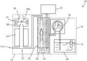
- FIG. 1is a diagram of a particle concentration analyzing system in accordance with the present invention
- FIG. 2is a flow diagram of a particle concentration analyzing system in accordance with the present invention.
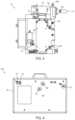
- FIG. 3is a rear elevation view of a particle concentration analyzing system in accordance with the present invention.
- FIG. 4is a front elevation view of the particle concentration analyzing system in accordance with the present invention.
- FIG. 5is a cross-sectional view of a capillary flow monitor for monitoring system flow in a particle concentration analyzing system
- FIG. 6is a cross-sectional view of a three way solenoid for drainage of a particle concentration analyzing system
- FIG. 6 ais a detail view of the 3-way solenoid valve of FIG. 6 in a “normally open” configuration
- FIG. 6 bis a detail view of the 3-way solenoid valve of FIG. 6 in a “normally closed” configuration
- FIG. 7is a cross-sectional view of a cooled solvent recovery system for recovery of working fluid in a particle concentration analyzing system
- FIG. 8is a flow diagram illustrating calibration of a particle concentration analyzing system
- FIG. 9is a perspective view of a particle concentration analyzing system in accordance with the present invention prepared for testing emissions of a vehicle;
- FIG. 10is an exploded perspective view of a particle concentration analyzing system in accordance with the present invention.
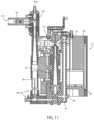
- FIG. 11is a cross-sectional view of a particle concentration analyzing system in accordance with the present invention.
- FIG. 11 Ais another cross-sectional view of the particle concentration analyzing system of FIG. 11 , depicting components and contents of a saturator of the particle concentration analyzing system.
- a system for analyzing particle concentration 10 in a fluidincluding a condensation particle counter (CPC) 12 , is provided to analyze a sample fluid or aerosol to determine a particle concentration or particle number in the sample ( FIG. 1 ).
- the analyzing system 10may be adapted to analyze various forms of fluid or aerosol samples, including engine exhaust, environmental atmosphere, power production exhaust, or the like, including for periodic technical inspections (PTI).
- the analyzing system 10is configured to operate with a working fluid, such as isopropyl alcohol (IPA) to supersaturate an ambient air flow.
- IPAisopropyl alcohol
- the saturated ambient air flowis mixed with a sample air and then the mixture of ambient air and sample air pass through a condenser where the supersaturated ambient air condenses onto particles in the sample air flow to grow the particles in the sample air flow to make them visible by an optical particle counter.
- the analyzing system 10includes a working fluid fill or refill system 16 for monitoring and automatically filling or refilling the working fluid in the analyzing system 10 .
- the working fluid fill system 16includes a pump 18 for filling and maintaining a sufficiently full level of working fluid in the analyzing system 10 .
- a working fluid tank 20is included with the particle analyzing system 10 to provide a source of working fluid to the analyzing system 10 .
- the analyzing system 10may be adapted for use in a testing facility where a trained operator can monitor and maintain the system 10 .
- the analyzing system 10may be adapted for portable use as a self-contained, portable, and robust particle analyzing system 10 a , such as field testing of farm equipment (see FIGS. 4 and 9 ).
- the CPC 12is configured to operate with a working fluid, such as isopropyl alcohol (IPA) to supersaturate an ambient air flow.
- IPAisopropyl alcohol
- the CPC 12is a mixing type CPC, such that the ambient air flow is super-saturated with the working fluid in a saturator block or fluid saturation chamber 22 , independent of a sample fluid (e.g. engine exhaust). After supersaturation is achieved, the saturated ambient air is mixed with the sample flow of fluid, air, or aerosol, between the saturator block 22 and a condenser 24 .
- the saturated ambient air flow and sample air flowmay be mixed in a mixing chamber 25 upstream of the condenser 24 , in the condenser 24 , or at a mixing junction 27 of the saturated flow and the sample flow.
- the mixture of the ambient air flow and the sample air flowthen pass through the condenser 24 where the supersaturated ambient air condenses onto particles in the sample air flow to grow the sample air particles to make them visible to the optical particle counter 14 .
- the condensation of the saturated ambient air onto the sample air particlescauses the sample air particles to grow into larger droplets, such as droplets that are 5-10 micrometers ( ⁇ m) in size.
- a fluid or air filter 23such as a HEPA filter, may be included with the analyzing system 10 upstream of the saturator 22 to filter unwanted particles from the ambient air, such unwanted particles might interfere with the results of the analysis.
- the grown particlesare focused or passed through a nozzle 28 having a wide end at or near an entrance side 14 a of the optical particle counter 14 and a narrower end proximate the laser beam 30 .
- the nozzle 28directs the grown particle flow in a substantially uniform flow through the optical field of the laser beam 30 and optical counter 14 .
- the optical counter 14counts the grown particles as the particles flow by the laser 30 by utilizing light scattering properties, such as with pulse detection electronics, to determine the number of sample air particles present in the sample fluid flow.
- the analyzed fluid flowis exhausted from an exhaust side 14 b of the optical counter 14 .
- the particle analyzing system 10includes an automatic working fluid fill system 16 to automatically monitor and refill working fluid in the saturator 22 as it is depleted during saturation of the HEPA filtered ambient air flow.
- the fluid fill system 16includes a working fluid pump 18 and a working fluid tank 20 .
- the pump 18draws working fluid from the working fluid tank 20 and pumps it into a reservoir portion 26 of the saturator block 22 .
- the pump 18is provided in the form of a peristaltic pump as commonly known for metering of fluids and controlling flow of a fluid through a tube in a bi-directional manner.
- a reservoir fluid level sensor 32is disposed at the reservoir portion 26 to monitor the level of working fluid in the saturator 22 .
- the fluid level sensor 32is in electronic communication with the pump 18 to maintain a sufficient level of working fluid in the saturator 22 to ensure proper operation of the analyzing system 10 .
- the automatic fill system 16mitigates fluid handling by a technician and reduces incidence of contamination of the working fluid.
- the analyzing system 10may include an electronic controller 34 in communication with the pump 18 and the fluid level sensor 32 that controls the pump 18 based on information received from the fluid level sensor 32 .
- the controller 34includes software adapted to control the analyzing system 10 .
- Embedded computersmay be provided with the software controller 34 to facilitate integration of web-based wireless communications, graphical user interfaces, or third party devices (e.g. Bluetooth on-board diagnostics, or USB based GPS modules) with the analyzing system 10 to control or monitor the system 10 .
- the electronic controllerincludes switches 35 to selectively operate different pumps in the analyzing system 10 .
- the working fluid tank 20requires periodic refilling and or replacement during normal use of the CPC 12 and analyzing system 10 .
- the working fluidmay be hydroscopic and flammable, such that safe handling of the working fluid is important.
- the working fluid tank 20may be sealed, such as with a self-sealable cap (e.g. with a septum), such that it does not spill if tipped over and such that the hydroscopic working fluid in the tank 20 is not exposed to water vapor that could contaminate the working fluid.
- the self-sealing cap(not shown) contains the fluid in the tank 20 and mitigates contamination and safety issues.
- the working fluid tank 20may include a molecular sieve to remove water from the working fluid.
- the working fluid tank 20 and working fluid pump 18are in fluid communication with the CPC 12 .
- the fluid tank 20 and fluid pump 18may be spaced away from the CPC 12 .
- the tank 20 and pump 18may be disconnected from the CPC 12 to be replaced or refilled.
- the working fluid pump 18is coupled to the saturator block 22 and the working fluid tank 20 is spaced away from the working fluid pump 18 such that the tank 20 may be disconnected from the pump 18 to be replaced or refilled.
- a housing 36contains and supports the CPC 12 and the fluid fill system 16 to provide a self-contained analyzing system 10 a ( FIGS. 4 and 9 ).
- the working fluid tank 20 of system 10 amay be removed from the system to be refilled or replaced.
- the working fluid tank 20 of system 10 amay be refilled from an external tank, such that removal from the housing 36 is unnecessary.
- the working fluid used in the analyzing system 10is greater than 99% isopropyl alcohol (IPA).
- Other fluidsmay be used for the working fluid, such as n-butanol.
- the working fluidis required to be maintained at a high purity (e.g. greater than 99% pure). Impurities (e.g. water) in the working fluid can change the vapor pressure/temperature relationship and cause inaccurate readings from the analyzing system 10 .
- the amount and purity of the IPA vapor generated in the saturator 22is critical for stable and accurate measurements. Isopropyl alcohol, n-butanol, and other working fluids are hydroscopic and thus can absorb water over time which decreases analysis efficiency of the analyzing system 10 .
- the working fluid tank 20can be supplied with a water absorbing material (not shown) to prevent or eliminate contamination or deterioration of the working fluid.
- the water absorbing material in the working fluid tank 20may be a 3A molecular sieve in the tank 20 to remove any water contamination from the ambient air prior to entering the saturator 22 and thus extend the fluid working lifetime.
- the working fluid consumption ratemay be 1-2 ml per hour.
- the saturator block reservoir 26has a capacity of 10 ml of liquid working fluid. Due to the low rate of consumption of working fluid, the analyzing system 10 is capable of operating over an extended period without the need to refill or replace the working fluid tank 20 .
- the working fluid consumption rate of 1-2 ml per houryields between about five (5) and ten (10) hours of continuous operation. For example, for a five (5) minute PTI test, about 60-120 PTI tests could be performed without refiling the saturator block reservoir 26 .
- the working fluid tank 20extends the operation duration of the analyzer up to several months and the capacity of the working fluid tank 20 may be selected to accommodate shorter or longer testing periods.
- the analyzing system 10includes at least one diffusion screen (not shown) upstream of the CPC 12 to improve test outcome quality. Diffusion screens upstream of the CPC 12 are included to increase the analyzing system 10 response to the currently established “automotive—PMP” criteria of 23 nm. The number of diffusion screens required can be selected to meet different d50 cut-off points.
- the CPC 12may be configured to automatically adjust the reported count of a particle concentration present in the laser measurement zone 30 a .
- the adjustment(“coincidence correction factor”) allows the optical counter 14 to count particles accurately even when the concentration of particles in the sample fluid are high.
- coincidence correction factorallows the optical counter 14 to count particles accurately even when the concentration of particles in the sample fluid are high.
- the CPC 12is capable of calibrated and validated analysis up to 30,000 #cm ⁇ 3 , representing an upper concentration in single count mode (non-diluted) for the analyzing system 10 .
- the analyzing systemincludes a dilution system, having an ejector diluter 40 , to facilitate single particle counting to concentrations of up to about 600,000 #cm-3.
- the dilution systemincludes a pump 42 is included upstream of the ejector dilutor 40 to provide dilution air flow to the ejector dilutor 40 through a dilutor input 40 a .
- the ejector diluter 40is configurable to dilute the sample flow of fluid nominally to a 20:1 dilution ratio.
- the ejector dilutor 40may be adjustable to modify the dilution ration.
- the ejector dilutor 40is also capable of overcoming humidity issues associated with testing vehicles and engines that emit high concentrations of water vapor (e.g. gasoline engines) by mixing the sample flow with ambient filtered dilution air.
- an additional ejector diluter(not shown) can be fitted with the analyzing system 10 .
- an additional dilution ejector dilutor having a dilution ration of 10:1can extend the upper concentration limit of the analyzing system 10 to 6,000,000 #cm-3.
- a filter 41such as a HEPA filter, may be provided with the ejector dilutor 40 to filter ambient air prior to entering the ejector dilutor 40 .
- Critical flows and pressures for the ejector dilutor 40 and additional ejector dilutorsare monitored and controlled by the controller 34 .
- the ejector dilutor 40is coupled to an exterior portion of the CPC 12 and provides cooling to the CPC 12 block via heat transfer from the CPC 12 block to the ejector dilutor 40 .
- the ejector diluter 40is integrated with the CPC, such that a mechanical pneumatic circuit (not shown) of the dilutor 40 is fully constrained and thus requires no unique verification for particle losses.
- the analyzing system 10may include an evaporator tube (not shown) for the removal of semi-volatile particles in the sample flow prior to the sample flow mixing with the saturated flow and entering the condenser 24 .
- the evaporatoris operated at about 300° C. and is capable of semi-volatile particle removal efficiency of greater than 95%, such as removal efficiency of tetracontane of greater than 95%.
- the analyzing system 10can be operated with the evaporator in an active or disabled configuration, which, for example, facilitates investigations of the likelihood of reporting a false vehicle PTI failure caused by the intermittent release of semi-volatile nano-particles by the vehicle or engine during testing.
- the analyzing system 10meets Swiss PTI performance criteria of the Switzerland Confederation Ordinance on Air Pollution Control (OAPC) 814.318.142.1.
- An exhaust or extract pump 44is included with the analyzing system 10 to draw fluid away from the CPC 12 after the fluid has been analyzed at the optical sensor 14 .
- the extract pump 44may be connected to a drain port 45 of the condenser 24 to drain the CPC 12 as required.
- the extract pumpis in electronic communication with the electronic controller 34 and is operable to turn on and off to exhaust the CPC 12 , to supplement fluid flow in the analyzing system 10 , to drain the analyzing system 10 , or to measure pressure values at various components of the analyzing system 10 .
- the analyzing system 10includes at least one differential pressure sensor or pressure transducer to measure two independent pressures and determine each individual pressure by periodically controlling the source of the pressure (e.g. turning a pump on or off).
- the analyzing system 10 of the illustrated embodiment of FIG. 2includes a differential pressure sensor 46 having two pressure measuring ports 46 a and 46 b .
- the two independent pressures, P 1 and P 2can be determined by measuring a pressure response (P) with periodic cycling of the sources for either P 1 or P 2 .
- the differential pressure sensor 46reduces the complexity of resources required for pressure response measurements because the electronics 34 required to turn off the dilution pump 42 or the exhaust pump 44 are simpler and cost a fraction of the cost of a complex pressure transducer.
- the interval between isolating one pressure source and measuring bothcan be determined and set by the stability of the pressure signals.
- the pressure sensor 46measures a negative pressure caused by the exhaust pump 44 and a positive pressure caused by the dilution air pump 42 .
- the pumps 42 , 44are controlled using the pump controller electronics 34 .
- the pressure sensor 46reports the total pressure difference between the two sources, the dilution pump 42 and the exhaust pump 44 .
- the pressure reportedis only the pressure caused by the exhaust pump 44 . The difference can be used to determine or calculate the dilution air pump pressure under normal operation.
- a flow measurement device or differential pressure sensor 48 having a precision capillary 50is included for flow measurements to reduce or eliminate the need for individual flow calibration in the various flow paths of the analyzing system 10 .
- Individual flow calibrationsmay be required when gas flowrates are determined by the measurement of pressures across a restriction, such as an extract orifice 52 .
- Precision manufactured capillaries 50such as hypodermic needles, are manufactured to tight engineering and surfaces tolerances and provide tight control tolerances for flow measurements by pressure drop, without the need for calibration.
- a flow rate 54 determined by a capillaryis shown in FIG. 5 with the corresponding differential pressure drop.
- the sample flow (e.g. engine exhaust) to be analyzed by the analyzing system 10is measured directly by a sample differential pressure sensor 56 including a sample flow precision capillary 58 .
- the sample flowcan be calculated directly using the sample capillary 58 of the sample sensor 56 , thereby reducing potential error sources and reducing complexity and costs of the analyzing system 10 .
- a 3-way solenoid valve 60is included to regulate fluid flows in the analyzing system 10 , and may be adapted to drain the CPC 12 of the analyzing system 10 , such as from a drain 45 at the condenser 24 .
- the 3-way valve 60eliminates the need for a real-time measurement of the drain flow.
- the 3-way solenoid valve 60is selectively operable to periodically drain fluid from the condenser 24 ( FIG. 6 ).
- the 3-way solenoid 60is controlled by the controller 34 to periodically switch the flow path from a “normally open” position 60 a to a “normally closed” position 60 b (see FIGS. 6 A and 6 B ).
- the 3-way solenoid valve 60includes fluid connections to the drain port 45 of the CPC 12 , the extract orifice 52 , and to the extract pump 44 .
- the extract and drain flows from the CPC 12contain working fluid in both the gaseous and liquid phases.
- the analyzing system 10includes a solvent or working fluid recovery system 64 to recover the gaseous and liquid phase working fluid from the extract and drain flows.
- the recovery system 64is coupled with the working fluid tank 20 to return recovered working fluid to the working fluid tank 20 to be reused in the analyzing system 10 .
- the exhaust pump 44pumps the extract and drain flows to a recovery inlet port 66 of the solvent recovery system 64 .
- the recovery system 64includes a vent 68 that is configured to vent vapor or gas from the recovery system 64 and also from the working fluid tank 20 .
- the recovery system 64reduces the concentration of the vapor being released through the vent 68 to recover some of the working fluid and reduce the overall working fluid consumption rate.
- the solvent recovery system 64includes a cooled heat exchanger 70 , such as a Peltier device, to condense the working fluid vapor inside the solvent recovery system 64 , the condensed working fluid falls back and is directed to return to the working fluid tank 20 by gravity.
- the analyzing system 10 illustrated in FIG. 7includes a working fluid tank level sensor 72 for monitoring the level of working fluid in the working fluid tank 20 and a working tank fill port 74 to refill the working fluid tank 20 .
- the tank sensor 72communicates the level of working fluid in the tank 20 to the controller 34 , which may then control the working fluid pump 18 to refill the working fluid tank 20 by drawing fluid from an external fluid tank (not shown) to the working fluid tank 20 .
- the controller 34may provide a signal or alert to an operator that the working fluid tank 20 needs to be refilled.
- a drain port 76 included with the analyzing system 10allows a user to drain the working fluid tank 20 , such as for cleaning or transportation of the system 10 .
- the analyzing systems 10 and 10 ainclude selectable calibration ports 78 , 80 to facilitate manual or automatic calibration of the various components in the analyzing system 10 without internal instrument access or dismantling or disassembly of the analyzing system 10 .
- Selectable port 78is configured for CPC 12 calibration and selectable port 80 is configured for combined calibration of the CPC 12 and ejector diluter 40 .
- Calibration of the analyzing system 10is performed by introducing an aerosol or fluid having a known reference particle number and size.
- Selectable ports 78 , 80can be connected to a calibration system 82 configured to determine the state of calibration of the analyzing system 10 and to calibrate a miss-calibrated analyzing system 10 ( FIG. 8 ).
- Calibration system 82includes a calibration manifold 84 , a controllable data management analysis software system 86 , a reference particle generator or source 88 , and a reference particle counting device 90 .
- the data management system 86is in electronic communication with the reference particle generator 88 and the reference particle counting device 90 .
- the calibration manifold 84is coupled to either selectable port 78 , 80 of one or more analyzing systems 10 .
- Each analyzing system 10 coupled to the calibration system 82is in electronic communication with the data management system 86 .
- the calibration system 82is controlled by the data management system 86 to calibrate or validate the analyzing system 10 .
- the reference particle generator 88generates a calibration fluid flow having a uniform particle number and particle size.
- the reference particle counter 90analyzes the calibration fluid flow to determine the uniform particle number and particle size being generated by the particle generator 88 .
- the calibration system 82 and calibration manifold 84may be configured to calibrate or validate multiple devices or systems 10 in parallel utilizing one reference particle generator 88 and one reference particle counting device 90 .
- the analyzing system 10includes a gas sensor system 92 for flow calibration or verification.
- the gas sensor system 92is capable of providing flow, measurement, calibration, and verification by determining a number of particles in a reference flow of a reference gas having a known particle density in parts per million.
- the gas sensor system 92includes a gas sensor 94 to facilitate a check of the system flows.
- the gas sensor 94has a parts per million (ppm) measurement range, such as between 0-10,000 ppm.
- a known concentration of carbon dioxideis introduced as a reference gas into the analyzing system 10 through a reference gas inlet or input port 96 .
- the particles in the reference gasare mixed or diluted with dilution air from the ejector dilutor 40 and then further diluted or mixed with saturated air from the CPC saturator 22 .
- the concentration of the reference gascan be measured at the exhaust of the ejector diluter 40 or at the CPC exhaust 52 and the measured concentrations can be calculated with the known concentration of the reference gas to validate the dilution ratios and the flows of the analyzing system 10 .
- the concentration at the exhaust of the ejector diluter 40should be 500 ppm (10,000 ppm ⁇ 20).
- the concentration of carbon dioxidewould be further reduced by the ratio of the CPC sample flow rate 54 divided by the saturator flow rate as it enters the CPC saturator 22 . If the measured concentration with the CO2 sensor 94 is within a pre-determined margin (e.g. ⁇ 5%) of the expected carbon dioxide concentrations at the ejector dilutor 40 exhaust or the CPC exhaust 52 , the flows and the analyzing system 10 are validated.
- the Carbon Dioxide sensor 94may be adapted to verify that the analyzing system 10 is properly configured by checking that a sampling probe 98 inserted into the engine (e.g. into an exhaust pipe of a vehicle) is inserted correctly (see FIG. 9 ).
- the sampling probe 98connects to the analyzing system 10 via a sampling line or hose 99 at a sample line vacuum input port 112 and collects or receives a sample fluid (e.g. engine exhaust) from a source, such as an exhaust pipe.
- the sampling probe 98is detachable from the analyzing system 10 , such that the analyzing system 10 is capable of receiving a sample fluid directly through the sample input port 112 .
- Enginesemit significant quantities of carbon dioxide (e.g.
- the carbon dioxide sensor 94provides an anti-cheat device to prevent users from purposely not inserting the sampling probe 98 sufficiently into the vehicle tailpipe in order to “pass” the vehicle.
- the concentration of carbon dioxide measured by the carbon dioxide sensor 94can be compared with the expected gas concentration (e.g. 16%) to verify that the sample probe 98 is properly inserted into the exhaust pipe and not receiving a diluted exhaust sample.
- the optical particle counter 14 in the CPC 12includes an optics chamber 114 having lenses (not shown) and a laser diode light source 30 a . Due to use of a working fluid in the analyzing system 10 to grow the particles prior to them being counted in the particle counter 14 , the working fluid may unwantedly migrate or be transported into the optics chamber 114 which could result in the optics being contaminated. Tipping or miss-orientation of the analyzing system 10 may allow working fluid to be pumped or transported to the optics chamber 114 while the analyzing system 10 is turned on. A safety or tip-over protection unit 116 is included with the analyzing system 10 .
- the safety unit 116includes a three-axis capacitive micro machined accelerometer (e.g.
- the safety unit 116communicates with the electronic controller 34 and the output from the accelerometer is sent to the controller 34 , which converts or calculates an instrument tilt angle. If the calculated angle is larger than a pre-determined safe angle or designed orientation, the controller 34 triggers a “protect mode” and turns off the pumps 18 , 42 , and 44 .
- a safe angle of operationmay be up to forty degrees from a vertical axis in any direction. The protect mode prevents damage and potentially costly repairs to the analyzing system 10 .
- the condition or purity of the working fluidis critical to the proper operation of the analyzing system 10 .
- Contamination or improper fillingmay degrade or render useless the working fluid in the analyzing system 10 , such as by filling the working fluid tank 20 with a wrong fluid.
- the level sensorseither the reservoir fluid level sensor 32 or the working fluid tank liquid level sensor 72 , could still report that the analyzing system 10 is ready for operation. Operating the analyzing system 10 with contaminated or wrong working fluid can cause damage to the various components of the analyzing system 10 .
- the analyzing system 10may be configured to verify that it is properly configured by monitoring and controlling the condition of the working fluid, such as by measuring the concentration of the working fluid in the extract flow with a gas purity sensor 48 disposed proximate the extract orifice 52 or providing a sealed tamperproof working fluid tank 20 or providing a sealed tamperproof bottle for an external refill container used to refill the working fluid tank 20 , as well as other contemplated options.
- the saturator 22 of the CPC 12includes a saturation material or wick 118 filling an interior void of the saturator 22 .
- the wick 118absorbs working fluid from the working fluid reservoir 26 , such that ambient air flowing through the saturator 22 passes through the wick 118 and the absorbed working fluid is available to saturate the ambient air in the saturator 22 .
- the wick 118provides increased efficiency during the saturation process to provide a higher level of super-saturation to the ambient air.
Landscapes
- Chemical & Material Sciences (AREA)
- Life Sciences & Earth Sciences (AREA)
- Health & Medical Sciences (AREA)
- Pathology (AREA)
- Physics & Mathematics (AREA)
- Analytical Chemistry (AREA)
- Biochemistry (AREA)
- General Health & Medical Sciences (AREA)
- General Physics & Mathematics (AREA)
- Immunology (AREA)
- Dispersion Chemistry (AREA)
- Molecular Biology (AREA)
- Biomedical Technology (AREA)
- Engineering & Computer Science (AREA)
- Sampling And Sample Adjustment (AREA)
- Investigating, Analyzing Materials By Fluorescence Or Luminescence (AREA)
Abstract
Description
Claims (20)
Priority Applications (1)
| Application Number | Priority Date | Filing Date | Title |
|---|---|---|---|
| US17/052,950US11686660B2 (en) | 2018-06-07 | 2019-06-06 | Particle concentration analyzing system and method |
Applications Claiming Priority (3)
| Application Number | Priority Date | Filing Date | Title |
|---|---|---|---|
| US201862681803P | 2018-06-07 | 2018-06-07 | |
| US17/052,950US11686660B2 (en) | 2018-06-07 | 2019-06-06 | Particle concentration analyzing system and method |
| PCT/IB2019/054740WO2019234688A2 (en) | 2018-06-07 | 2019-06-06 | Particle concentration analyzing system and method |
Publications (2)
| Publication Number | Publication Date |
|---|---|
| US20210231551A1 US20210231551A1 (en) | 2021-07-29 |
| US11686660B2true US11686660B2 (en) | 2023-06-27 |
Family
ID=68770117
Family Applications (1)
| Application Number | Title | Priority Date | Filing Date |
|---|---|---|---|
| US17/052,950Active2039-11-28US11686660B2 (en) | 2018-06-07 | 2019-06-06 | Particle concentration analyzing system and method |
Country Status (7)
| Country | Link |
|---|---|
| US (1) | US11686660B2 (en) |
| EP (1) | EP3803317B1 (en) |
| JP (1) | JP2021527198A (en) |
| KR (1) | KR20210018259A (en) |
| CN (1) | CN112236661A (en) |
| ES (1) | ES2994493T3 (en) |
| WO (1) | WO2019234688A2 (en) |
Families Citing this family (12)
| Publication number | Priority date | Publication date | Assignee | Title |
|---|---|---|---|---|
| CN111122419A (en)* | 2019-12-05 | 2020-05-08 | 中国科学院合肥物质科学研究院 | Condensation particle counter |
| US20210108937A1 (en)* | 2020-12-21 | 2021-04-15 | Maik Sven FOX | Fleet emission control, distribution, and limits adherence |
| CN112710591A (en)* | 2021-01-19 | 2021-04-27 | 南昌智能新能源汽车研究院 | Device and method for verifying dilution ratio control precision of emission test equipment |
| CN113188852A (en)* | 2021-04-28 | 2021-07-30 | 哈尔滨工程大学 | Sampling and measuring device for micro-nano aerosol in different environments |
| WO2022235318A1 (en)* | 2021-05-07 | 2022-11-10 | Tsi Incorporated | Aerosol-based liquid particle detection measurement |
| CN112986070B (en)* | 2021-05-12 | 2021-08-17 | 西安多普多信息科技有限公司 | Tail gas detection device, method and system |
| CN113720749B (en)* | 2021-08-31 | 2023-01-17 | 北京航空航天大学 | Wide temperature range nano-particle counter |
| CN114034612A (en)* | 2021-09-22 | 2022-02-11 | 廖旎焕 | Method for detecting combustible thermal escape tiny particulate matter and application thereof |
| KR102352118B1 (en) | 2021-09-29 | 2022-01-18 | 주식회사 거남 | Foreign Matter Change Measurement System In The Pre-Treatment Tank Of A Painting Factory |
| KR102410143B1 (en) | 2021-12-03 | 2022-06-23 | (주)그린텍아이엔씨 | Smart single channel particle counter |
| KR102394276B1 (en)* | 2021-12-30 | 2022-05-04 | 주식회사 거남 | Pretreatment Tank Pollution Level Tracking System for Paint Shop |
| TW202507252A (en)* | 2023-02-07 | 2025-02-16 | 美商粒子監測系統有限公司 | Polydispersed particle challenge sample volume calibration of optical particle counters |
Citations (131)
| Publication number | Priority date | Publication date | Assignee | Title |
|---|---|---|---|---|
| US3694085A (en) | 1970-09-10 | 1972-09-26 | Environment One Corp | Mixing type condensation nuclei meter |
| US3721804A (en) | 1970-12-16 | 1973-03-20 | Tsi Inc | Apparatus for sealing and shrinking plastic film |
| US3849178A (en) | 1970-11-11 | 1974-11-19 | Tsi Inc | Thermal protective process and article coated with thermal protective composition |
| US3877200A (en) | 1973-06-06 | 1975-04-15 | Tsi Inc | Capping device |
| CA990007A (en) | 1973-09-21 | 1976-06-01 | T.S.I. | Thermal protective process compositions for use therein and method of making them |
| SE394893B (en) | 1970-11-11 | 1977-07-18 | Tsi Inc | INTUMESCENT HEAT PROTECTION COMPOSITION CONTAINING SILICATE SALT OF AN ORGANIC AMINE AND A BINDER |
| GB1497659A (en) | 1974-11-14 | 1978-01-12 | Tsi Inc | Thermal protecting process and composition |
| US4263002A (en) | 1979-04-20 | 1981-04-21 | Tsi Incorporated | Differential doppler technique for on-axis backscatter measurements |
| US4293217A (en) | 1980-02-06 | 1981-10-06 | The United States Of America As Represented By The Secretary Of The Army | Continuous-flow condensation nuclei counter and process |
| US4331037A (en) | 1980-06-02 | 1982-05-25 | Tsi Incorporated | Fluid flow measuring apparatus |
| US4387993A (en) | 1981-06-25 | 1983-06-14 | Tsi Incorporated | Particle size measuring method and apparatus |
| US4394825A (en) | 1980-06-02 | 1983-07-26 | Tsi Incorporated | Fluid flow measuring apparatus |
| DK233282A (en) | 1982-05-24 | 1983-11-25 | Tsi Inc | DEVICE FOR MEASURING THE SPEED AND / OR DIRECTION OF A MEDIUM |
| EP0095000A1 (en) | 1982-05-25 | 1983-11-30 | TSI Incorporated | Fluid flow measuring apparatus |
| US4449816A (en) | 1981-05-11 | 1984-05-22 | Nitta Gelatin Kabushiki Kaisha | Method for measuring the number of hyperfine particles and a measuring system therefor |
| US4471654A (en) | 1981-09-25 | 1984-09-18 | Tsi Incorporated | Fluid flow measuring apparatus |
| US4503706A (en) | 1983-05-16 | 1985-03-12 | Kenneth J. Kolodjski | Constant temperature anemometer |
| US4523462A (en) | 1983-05-16 | 1985-06-18 | Tsi Incorporated | Constant temperature anemometer having an enhanced frequency response |
| FR2570829A1 (en) | 1985-09-20 | 1986-03-28 | Tsi Inc | Hot-wire anemometer of the balanced resistance bridge type |
| NZ205034A (en) | 1982-08-23 | 1986-06-11 | Tsi Inc | Thermal protective structure:coated mesh support with spacers |
| US4596140A (en) | 1984-09-21 | 1986-06-24 | Tsi Incorporated | Constant overheat anemometer with sensor lead wire impedance compensation |
| US4772081A (en) | 1986-09-15 | 1988-09-20 | Tsi Incorporated | Fiber optic connector assembly |
| US4787251A (en) | 1987-07-15 | 1988-11-29 | Tsi Incorporated | Directional low differential pressure transducer |
| US4790650A (en) | 1987-04-17 | 1988-12-13 | Tsi Incorporated | Condensation nucleus counter |
| US4843564A (en) | 1987-04-23 | 1989-06-27 | Tsi Incorporated | Apparatus and method for measuring frequency of coherent component of a composite signal |
| US4875755A (en) | 1986-09-15 | 1989-10-24 | Tsi Incorporated | Fiber optic connector assembly and method of making same |
| US4948257A (en) | 1987-09-14 | 1990-08-14 | Tsi Incorporated | Laser optical measuring device and method for stabilizing fringe pattern spacing |
| US4950073A (en) | 1989-02-10 | 1990-08-21 | Pacific Scientific Company | Submicron particle counting enlarging the particles in a condensation based growth process |
| WO1990010858A1 (en) | 1989-03-06 | 1990-09-20 | Tsi Incorporated | Single particle detector using light scattering techniques |
| US4973969A (en) | 1990-01-16 | 1990-11-27 | Tsi Incorporated | Coherent frequency burst detector apparatus and method |
| US5026155A (en) | 1989-09-06 | 1991-06-25 | Air Products And Chemicals, Inc. | Process for sizing particles using condensation nucleus counting |
| US5076097A (en) | 1990-06-28 | 1991-12-31 | Tsi Incorporated | Method and apparatus for determining concentration of macromolecules and colloids in a liquid sample |
| US5084614A (en) | 1990-09-21 | 1992-01-28 | Tsi Incorporated | Optical single particle detector with lenseless fiber optic probe |
| US5085500A (en) | 1989-11-28 | 1992-02-04 | Tsi Incorporated | Non-imaging laser particle counter |
| US5098657A (en) | 1989-08-07 | 1992-03-24 | Tsi Incorporated | Apparatus for measuring impurity concentrations in a liquid |
| US5118959A (en) | 1991-05-03 | 1992-06-02 | Tsi Incorporated | Water separation system for condensation particle counter |
| US5121988A (en) | 1989-10-04 | 1992-06-16 | Tsi Incorporated | Single particle detector method and apparatus utilizing light extinction within a sheet of light |
| US5239356A (en) | 1990-06-20 | 1993-08-24 | Fraunhofer-Gesellschaft Zur Forderung Der Angewandten Forschung Ev | Condensation nucleus counter |
| US5247842A (en) | 1991-09-30 | 1993-09-28 | Tsi Incorporated | Electrospray apparatus for producing uniform submicrometer droplets |
| US5262841A (en) | 1991-10-16 | 1993-11-16 | Tsi Incorporated | Vacuum particle detector |
| US5343744A (en) | 1992-03-06 | 1994-09-06 | Tsi Incorporated | Ultrasonic anemometer |
| US5351523A (en) | 1993-01-21 | 1994-10-04 | Tsi Incorporated | Apparatus and process for determining filter efficiency in removing colloidal suspensions |
| US5374396A (en) | 1992-05-05 | 1994-12-20 | Tsi Incorporated | Syringe injection system for measuring non-volatile residue in solvents |
| US5453837A (en) | 1993-07-19 | 1995-09-26 | Tsi Incorporated | Interferometric device for determining sizes and properties of cylindrical objects based on phase shift measurements |
| US5513004A (en) | 1994-08-12 | 1996-04-30 | Tsi Incorporated | Device for interferometric measurements with compensation for tilt and position of measured cylindrical objects |
| US5561515A (en) | 1994-10-07 | 1996-10-01 | Tsi Incorporated | Apparatus for measuring particle sizes and velocities |
| WO1997006525A1 (en) | 1995-08-03 | 1997-02-20 | Tsi Incorporated | Digital burst frequency translator |
| US5675405A (en) | 1996-08-12 | 1997-10-07 | Met One, Inc. | Condensation nucleus counter employing supersaturation by thermal differentiation |
| US5684587A (en) | 1996-07-05 | 1997-11-04 | Tsi Incorporated | Device and process for interferometric sizing of particles using spatial filtering of scattered radiation |
| US5784160A (en) | 1995-10-10 | 1998-07-21 | Tsi Corporation | Non-contact interferometric sizing of stochastic particles |
| WO1998041876A1 (en) | 1997-03-17 | 1998-09-24 | Tsi Incorporated | System for detecting fluorescing components in aerosols |
| US5872622A (en) | 1996-08-12 | 1999-02-16 | Met One, Inc. | Condensation nucleus counter having vapor stabilization and working fluid recovery |
| US5903338A (en) | 1998-02-11 | 1999-05-11 | Particle Measuring Systems, Inc. | Condensation nucleus counter using mixing and cooling |
| US6064473A (en) | 1997-04-15 | 2000-05-16 | Kanomax Japan Incorporated | Particle measuring apparatus and its calibration method |
| DE19859211A1 (en) | 1998-12-21 | 2000-07-20 | Grimm Aerosol Technik Gmbh & C | Apparatus accurately determining particle size distribution and total concentration in moist sample gas stream, uses laser light pulses of differing intensity to reveal coarse and finest particles down to sub-micron sizes |
| US6125845A (en) | 1997-08-29 | 2000-10-03 | Tsi Incorporated | Respirator fit-testing with size selected aerosol |
| US6158293A (en) | 1996-04-09 | 2000-12-12 | Tsi Incorporated | Apparatus for determining powder flowability |
| US6158431A (en) | 1998-02-13 | 2000-12-12 | Tsi Incorporated | Portable systems and methods for delivery of therapeutic material to the pulmonary system |
| US6230572B1 (en) | 1998-02-13 | 2001-05-15 | Tsi Incorporated | Instrument for measuring and classifying nanometer aerosols |
| DE10030134A1 (en) | 2000-06-20 | 2002-01-10 | Grimm Aerosol Technik Gmbh & C | Device for determining concentration of microorganisms in gas, comprises measurement cell through which sample gas stream flows and in which light beam is scattered on particles in gas stream |
| US6469780B1 (en) | 1998-12-21 | 2002-10-22 | Air Products And Chemicals, Inc. | Apparatus and method for detecting particles in reactive and toxic gases |
| US20020157446A1 (en) | 1999-04-07 | 2002-10-31 | Dilger John P. | Pressure activated calibration system for chemical sensors |
| US6498641B1 (en) | 2001-06-01 | 2002-12-24 | Pacific Scientific Instruments Company | Condensation nucleus counter with multi-directional fluid flow system |
| US6567157B1 (en) | 1999-10-12 | 2003-05-20 | California Institute Of Technology | Fast mixing condensation nucleus counter |
| US20030199100A1 (en) | 2000-09-15 | 2003-10-23 | Wick Charles Harold | Method and system for detecting and recording submicron sized particles |
| US20040140327A1 (en)* | 2003-01-02 | 2004-07-22 | Osborne Michael D. | Pressurized fluid dispenser |
| US6829044B2 (en) | 2002-04-24 | 2004-12-07 | Msp Corporation | Compact, high-efficiency condensation nucleus counter |
| WO2005039780A2 (en) | 2003-10-16 | 2005-05-06 | Tsi Incorporated | Aerosol charge altering device |
| WO2005114131A2 (en) | 2004-05-10 | 2005-12-01 | Tsi Incorporated | Particle surface treatment for promoting condensation |
| US6980284B2 (en) | 2000-09-25 | 2005-12-27 | Hyundai Calibration & Certification Technologies Co., Ltd. | Condensation particle counter |
| EP1655595A1 (en) | 2004-11-03 | 2006-05-10 | Heinz Burtscher | Method and device for measuring number concentration and mean diameter of particles suspended in a carrier gas |
| US20060096394A1 (en) | 2004-11-09 | 2006-05-11 | Nelson David D Jr | Extractive sampling system and method for measuring one or more molecular species |
| US20060126056A1 (en) | 2002-09-18 | 2006-06-15 | Roberts Gregory C | Stream-wise thermal gradient cloud condensation nuclei chamber |
| US20060266133A1 (en)* | 2005-05-27 | 2006-11-30 | Dong-Hyun Kim | Flow indicator and apparatus for monitoring particles in air |
| WO2006127803A2 (en) | 2005-05-23 | 2006-11-30 | Tsi Incorporated | Instruments for measuring nanoparticle exposure |
| US20070039295A1 (en)* | 2004-08-31 | 2007-02-22 | Ibiden Co., Ltd. | Exhaust gas cleanup system |
| US20070047836A1 (en) | 2005-09-01 | 2007-03-01 | Gang Pan | Analysis of signal oscillation patterns |
| US20070056395A1 (en) | 2005-09-15 | 2007-03-15 | Korea Institute Of Science And Technology | Particle counter |
| US20080047373A1 (en) | 2006-07-12 | 2008-02-28 | Ahn Kang H | Particle measuring system and method |
| GB2443110A (en) | 2005-05-23 | 2008-04-23 | Tsi Inc | Instruments for measuring nanoparticle exposure |
| US7363828B2 (en) | 2005-08-25 | 2008-04-29 | Msp Corporation | Aerosol measurement by dilution and particle counting |
| US20080152547A1 (en) | 2006-12-22 | 2008-06-26 | Thermo Electron Corporation | Devices, methods, and systems for detecting particles in aerosol gas streams |
| US20080186489A1 (en) | 2007-02-02 | 2008-08-07 | Kang Ho Ahn | Condensation particle counter |
| US20090031828A1 (en)* | 2004-01-08 | 2009-02-05 | Dekati Oy | Method and apparatus for increasing the size of small particles |
| US20090143503A1 (en)* | 2007-11-30 | 2009-06-04 | Eduardo Romero-Nochebuena | Methods for incorporating polyvinyl alcohol particles into products |
| WO2009103063A2 (en) | 2008-02-15 | 2009-08-20 | Tsi Incorporated | An automated qualitative mask fit tester |
| US7647811B2 (en) | 2006-12-21 | 2010-01-19 | Horiba Ltd. | Solid particle counting system with valve to allow reduction of pressure pulse at particle counter when vacuum pump is started |
| WO2010039861A2 (en) | 2008-09-30 | 2010-04-08 | The Regents Of The University Of Michigan | Dendrimer conjugates |
| US7724368B2 (en) | 2007-07-05 | 2010-05-25 | Kang Ho Ahn | Condensation particle counter |
| WO2010085085A2 (en) | 2009-01-20 | 2010-07-29 | (주)에이치시티 | Particle-measuring unit |
| US7796727B1 (en) | 2008-03-26 | 2010-09-14 | Tsi, Incorporated | Aerosol charge conditioner |
| US7806968B2 (en) | 2007-10-16 | 2010-10-05 | Horiba Ltd. | Calibration unit for volatile particle remover |
| US20110259426A1 (en) | 2007-08-01 | 2011-10-27 | Cavagna Group Spa. | Electronic Flow Sensor |
| US8047055B2 (en) | 2007-08-08 | 2011-11-01 | Tsi, Incorporated | Size segregated aerosol mass concentration measurement with inlet conditioners and multiple detectors |
| DE10084713B3 (en) | 1999-06-18 | 2012-03-29 | Tsi Incorporated | A charge-adjusted aerosol generating system, a method of ionizing an aerosol, a method of identifying a nonvolatile material, and a corona discharge aerosol landing adjustment device |
| US8208132B2 (en) | 2009-01-19 | 2012-06-26 | Avl List Gmbh | Condensation nucleus counter |
| DE102005001992B4 (en) | 2005-01-15 | 2012-08-02 | Palas Gmbh Partikel- Und Lasermesstechnik | Method and device for counting particles |
| US20120222495A1 (en)* | 2009-08-24 | 2012-09-06 | Particle Measuring Systems, Inc. | Flow monitored particle sensor |
| JP5170004B2 (en) | 2009-06-08 | 2013-03-27 | 株式会社島津製作所 | Aerosol particulate measuring device |
| US8465791B2 (en) | 2009-10-16 | 2013-06-18 | Msp Corporation | Method for counting particles in a gas |
| CN103175767A (en) | 2011-12-22 | 2013-06-26 | 株式会社堀场制作所 | Particle number counting apparatus and saturated part |
| JP2013190246A (en) | 2012-03-13 | 2013-09-26 | Shimadzu Corp | Aerosol fine particle measuring device |
| US20140060155A1 (en) | 2012-08-31 | 2014-03-06 | Tsi Incorporated | System and method for the concentrated collection of airborne particles |
| WO2014033040A1 (en) | 2012-08-30 | 2014-03-06 | Naneos Particle Solutions Gmbh | Aerosol measuring device and method |
| US20140172315A1 (en)* | 2012-12-17 | 2014-06-19 | Abbott Point Of Care Inc. | Operation and Verification of A Portable Clinical Analysis System |
| US20140268476A1 (en) | 2013-03-15 | 2014-09-18 | Tsi Incorporated | Method and system for significantly improving charge probabilities of nanometer aerosol particles |
| US20140284204A1 (en) | 2013-03-22 | 2014-09-25 | Airmodus Oy | Method and device for ionizing particles of a sample gas glow |
| US20140339415A1 (en) | 2012-01-20 | 2014-11-20 | Tsi, Incorporated | Instrument for sizing nanoparticles and a component therefor |
| US20140347663A1 (en) | 2011-10-26 | 2014-11-27 | Research Triangle Institute | Aerosol exposure monitoring |
| US20140354976A1 (en) | 2011-09-20 | 2014-12-04 | Tsi, Incorporated | Apparatus and system for characterizing an aerosol particle flow |
| US8943873B2 (en) | 2009-06-05 | 2015-02-03 | Airmodus Oy | Method and device for detecting aerosol particles |
| US20150160105A1 (en) | 2011-04-13 | 2015-06-11 | Tsi, Incorporation | Apparatus and method for improving particle count accuracy in low pressure applications |
| CN104880339A (en) | 2015-06-18 | 2015-09-02 | 吉林大学 | Gasoline direct-injection engine exhaust particulate thermodilution sampling system |
| US9194234B2 (en) | 2012-08-06 | 2015-11-24 | Mitsubishi Heavy Industries, Ltd. | Fixture for connecting rotors of rotary machine and method of connecting rotors |
| CN105334146A (en) | 2015-10-16 | 2016-02-17 | 北京航空航天大学 | Detection device used for direct measuring of engine tail gas particulate matter number concentration |
| US20160059249A1 (en) | 2014-08-26 | 2016-03-03 | Tsi, Inc. | Electrospray with soft x-ray neutralizer |
| US20160061709A1 (en) | 2014-08-28 | 2016-03-03 | Tsi, Inc. | Detection system for determining filtering effectiveness of airborne molecular contamination |
| US20160178434A1 (en) | 2013-08-02 | 2016-06-23 | Tsi, Inc. | High speed spectroscopic sensor assembly and system |
| WO2016133834A2 (en) | 2015-02-16 | 2016-08-25 | Tsi, Inc. | Air and gas flow velocity and temperature sensor probe |
| CN106030289A (en) | 2013-10-16 | 2016-10-12 | Tsi公司 | Handheld laser induced breakdown spectroscopy device |
| CN106290744A (en) | 2016-10-19 | 2017-01-04 | 舟山市质量技术监督检测研究院 | Exhaust analyzer calibrating installation |
| CA3010613A1 (en) | 2016-01-08 | 2017-07-13 | Tsi, Inc. | Wearable mask fit monitor |
| US9726579B2 (en) | 2014-12-02 | 2017-08-08 | Tsi, Incorporated | System and method of conducting particle monitoring using low cost particle sensors |
| CN107107122A (en) | 2014-06-23 | 2017-08-29 | Tsi公司 | Rapid Material Analysis Using LIBS Spectroscopy |
| US20170276589A1 (en) | 2016-03-23 | 2017-09-28 | Derek Oberreit | Compact condensation particle counter technology |
| US20170299487A1 (en)* | 2016-04-14 | 2017-10-19 | Applied Materials, Inc. | 30 nm in-line lpc testing and cleaning of semiconductor processing equipment |
| US20180045636A1 (en) | 2015-02-23 | 2018-02-15 | Tsi Incorporated | Condensation particle counter false count performance |
| TW201805612A (en) | 2016-06-30 | 2018-02-16 | 加野麥克斯Fmt股份有限公司 | Colloid particle size-mass distribution measurement technology |
| WO2018058236A1 (en) | 2016-09-29 | 2018-04-05 | Clad Innovations Ltd. | Highly integrated optical particle counter (opc) |
| US20180136106A1 (en) | 2015-04-16 | 2018-05-17 | Palas Gmbh Partikel-Und Lasermesstechnik | Device for counting particles |
| US20190195765A1 (en)* | 2017-12-22 | 2019-06-27 | Industrial Technology Research Institute | Particle counting method and device |
Family Cites Families (7)
| Publication number | Priority date | Publication date | Assignee | Title |
|---|---|---|---|---|
| JPH09288053A (en)* | 1996-02-22 | 1997-11-04 | Hitachi Ltd | Particle analyzer |
| JP3851531B2 (en)* | 2001-10-03 | 2006-11-29 | 株式会社堀場製作所 | Particulate matter measuring apparatus and method |
| JP4985202B2 (en)* | 2007-08-08 | 2012-07-25 | 株式会社豊田中央研究所 | Exhalation determination device |
| JP5171344B2 (en)* | 2008-03-28 | 2013-03-27 | 東京エレクトロン株式会社 | Particle detection system, particle detection method and program |
| AT509962B1 (en)* | 2011-09-12 | 2015-05-15 | Avl List Gmbh | METHOD AND DEVICE FOR DETERMINING THE CONCENTRATION OF AEROSOLS IN HOT GASES, ESPECIALLY IN EXHAUST GASES FROM COMBUSTION ENGINES |
| JP6147082B2 (en)* | 2013-05-17 | 2017-06-14 | 公益財団法人日本自動車輸送技術協会 | Exhaust gas analysis system, exhaust gas sampling device, and exhaust gas leak detection method |
| JP2017009466A (en)* | 2015-06-23 | 2017-01-12 | 富士電機株式会社 | Calibration method for particle composite analyzer and particle composite analyzer |
- 2019
- 2019-06-06ESES19814777Tpatent/ES2994493T3/enactiveActive
- 2019-06-06EPEP19814777.9Apatent/EP3803317B1/enactiveActive
- 2019-06-06JPJP2020567780Apatent/JP2021527198A/enactivePending
- 2019-06-06WOPCT/IB2019/054740patent/WO2019234688A2/ennot_activeCeased
- 2019-06-06KRKR1020207034711Apatent/KR20210018259A/enactivePending
- 2019-06-06CNCN201980037259.4Apatent/CN112236661A/enactivePending
- 2019-06-06USUS17/052,950patent/US11686660B2/enactiveActive
Patent Citations (139)
| Publication number | Priority date | Publication date | Assignee | Title |
|---|---|---|---|---|
| US3694085A (en) | 1970-09-10 | 1972-09-26 | Environment One Corp | Mixing type condensation nuclei meter |
| US3849178A (en) | 1970-11-11 | 1974-11-19 | Tsi Inc | Thermal protective process and article coated with thermal protective composition |
| SE394893B (en) | 1970-11-11 | 1977-07-18 | Tsi Inc | INTUMESCENT HEAT PROTECTION COMPOSITION CONTAINING SILICATE SALT OF AN ORGANIC AMINE AND A BINDER |
| US3721804A (en) | 1970-12-16 | 1973-03-20 | Tsi Inc | Apparatus for sealing and shrinking plastic film |
| US3877200A (en) | 1973-06-06 | 1975-04-15 | Tsi Inc | Capping device |
| CA990007A (en) | 1973-09-21 | 1976-06-01 | T.S.I. | Thermal protective process compositions for use therein and method of making them |
| GB1497659A (en) | 1974-11-14 | 1978-01-12 | Tsi Inc | Thermal protecting process and composition |
| US4263002A (en) | 1979-04-20 | 1981-04-21 | Tsi Incorporated | Differential doppler technique for on-axis backscatter measurements |
| US4293217A (en) | 1980-02-06 | 1981-10-06 | The United States Of America As Represented By The Secretary Of The Army | Continuous-flow condensation nuclei counter and process |
| US4331037A (en) | 1980-06-02 | 1982-05-25 | Tsi Incorporated | Fluid flow measuring apparatus |
| US4394825A (en) | 1980-06-02 | 1983-07-26 | Tsi Incorporated | Fluid flow measuring apparatus |
| US4449816A (en) | 1981-05-11 | 1984-05-22 | Nitta Gelatin Kabushiki Kaisha | Method for measuring the number of hyperfine particles and a measuring system therefor |
| US4387993A (en) | 1981-06-25 | 1983-06-14 | Tsi Incorporated | Particle size measuring method and apparatus |
| US4471654A (en) | 1981-09-25 | 1984-09-18 | Tsi Incorporated | Fluid flow measuring apparatus |
| DK233282A (en) | 1982-05-24 | 1983-11-25 | Tsi Inc | DEVICE FOR MEASURING THE SPEED AND / OR DIRECTION OF A MEDIUM |
| EP0095000A1 (en) | 1982-05-25 | 1983-11-30 | TSI Incorporated | Fluid flow measuring apparatus |
| NZ205034A (en) | 1982-08-23 | 1986-06-11 | Tsi Inc | Thermal protective structure:coated mesh support with spacers |
| US4503706A (en) | 1983-05-16 | 1985-03-12 | Kenneth J. Kolodjski | Constant temperature anemometer |
| US4523462A (en) | 1983-05-16 | 1985-06-18 | Tsi Incorporated | Constant temperature anemometer having an enhanced frequency response |
| US4596140A (en) | 1984-09-21 | 1986-06-24 | Tsi Incorporated | Constant overheat anemometer with sensor lead wire impedance compensation |
| FR2570829A1 (en) | 1985-09-20 | 1986-03-28 | Tsi Inc | Hot-wire anemometer of the balanced resistance bridge type |
| US4772081A (en) | 1986-09-15 | 1988-09-20 | Tsi Incorporated | Fiber optic connector assembly |
| US4875755A (en) | 1986-09-15 | 1989-10-24 | Tsi Incorporated | Fiber optic connector assembly and method of making same |
| US4790650A (en) | 1987-04-17 | 1988-12-13 | Tsi Incorporated | Condensation nucleus counter |
| US4843564A (en) | 1987-04-23 | 1989-06-27 | Tsi Incorporated | Apparatus and method for measuring frequency of coherent component of a composite signal |
| US4787251A (en) | 1987-07-15 | 1988-11-29 | Tsi Incorporated | Directional low differential pressure transducer |
| US4948257A (en) | 1987-09-14 | 1990-08-14 | Tsi Incorporated | Laser optical measuring device and method for stabilizing fringe pattern spacing |
| US4950073A (en) | 1989-02-10 | 1990-08-21 | Pacific Scientific Company | Submicron particle counting enlarging the particles in a condensation based growth process |
| WO1990010858A1 (en) | 1989-03-06 | 1990-09-20 | Tsi Incorporated | Single particle detector using light scattering techniques |
| US5098657A (en) | 1989-08-07 | 1992-03-24 | Tsi Incorporated | Apparatus for measuring impurity concentrations in a liquid |
| US5026155A (en) | 1989-09-06 | 1991-06-25 | Air Products And Chemicals, Inc. | Process for sizing particles using condensation nucleus counting |
| US5121988A (en) | 1989-10-04 | 1992-06-16 | Tsi Incorporated | Single particle detector method and apparatus utilizing light extinction within a sheet of light |
| US5085500A (en) | 1989-11-28 | 1992-02-04 | Tsi Incorporated | Non-imaging laser particle counter |
| US4973969A (en) | 1990-01-16 | 1990-11-27 | Tsi Incorporated | Coherent frequency burst detector apparatus and method |
| US5239356A (en) | 1990-06-20 | 1993-08-24 | Fraunhofer-Gesellschaft Zur Forderung Der Angewandten Forschung Ev | Condensation nucleus counter |
| US5076097A (en) | 1990-06-28 | 1991-12-31 | Tsi Incorporated | Method and apparatus for determining concentration of macromolecules and colloids in a liquid sample |
| US5084614A (en) | 1990-09-21 | 1992-01-28 | Tsi Incorporated | Optical single particle detector with lenseless fiber optic probe |
| US5118959A (en) | 1991-05-03 | 1992-06-02 | Tsi Incorporated | Water separation system for condensation particle counter |
| US5247842A (en) | 1991-09-30 | 1993-09-28 | Tsi Incorporated | Electrospray apparatus for producing uniform submicrometer droplets |
| US5262841A (en) | 1991-10-16 | 1993-11-16 | Tsi Incorporated | Vacuum particle detector |
| US5343744A (en) | 1992-03-06 | 1994-09-06 | Tsi Incorporated | Ultrasonic anemometer |
| US5374396A (en) | 1992-05-05 | 1994-12-20 | Tsi Incorporated | Syringe injection system for measuring non-volatile residue in solvents |
| US5351523A (en) | 1993-01-21 | 1994-10-04 | Tsi Incorporated | Apparatus and process for determining filter efficiency in removing colloidal suspensions |
| US5453837A (en) | 1993-07-19 | 1995-09-26 | Tsi Incorporated | Interferometric device for determining sizes and properties of cylindrical objects based on phase shift measurements |
| US5513004A (en) | 1994-08-12 | 1996-04-30 | Tsi Incorporated | Device for interferometric measurements with compensation for tilt and position of measured cylindrical objects |
| US5561515A (en) | 1994-10-07 | 1996-10-01 | Tsi Incorporated | Apparatus for measuring particle sizes and velocities |
| WO1997006525A1 (en) | 1995-08-03 | 1997-02-20 | Tsi Incorporated | Digital burst frequency translator |
| US5784160A (en) | 1995-10-10 | 1998-07-21 | Tsi Corporation | Non-contact interferometric sizing of stochastic particles |
| US6158293A (en) | 1996-04-09 | 2000-12-12 | Tsi Incorporated | Apparatus for determining powder flowability |
| US5684587A (en) | 1996-07-05 | 1997-11-04 | Tsi Incorporated | Device and process for interferometric sizing of particles using spatial filtering of scattered radiation |
| US5872622A (en) | 1996-08-12 | 1999-02-16 | Met One, Inc. | Condensation nucleus counter having vapor stabilization and working fluid recovery |
| US5675405A (en) | 1996-08-12 | 1997-10-07 | Met One, Inc. | Condensation nucleus counter employing supersaturation by thermal differentiation |
| WO1998041876A1 (en) | 1997-03-17 | 1998-09-24 | Tsi Incorporated | System for detecting fluorescing components in aerosols |
| US6064473A (en) | 1997-04-15 | 2000-05-16 | Kanomax Japan Incorporated | Particle measuring apparatus and its calibration method |
| US6125845A (en) | 1997-08-29 | 2000-10-03 | Tsi Incorporated | Respirator fit-testing with size selected aerosol |
| US5903338A (en) | 1998-02-11 | 1999-05-11 | Particle Measuring Systems, Inc. | Condensation nucleus counter using mixing and cooling |
| US6158431A (en) | 1998-02-13 | 2000-12-12 | Tsi Incorporated | Portable systems and methods for delivery of therapeutic material to the pulmonary system |
| US6230572B1 (en) | 1998-02-13 | 2001-05-15 | Tsi Incorporated | Instrument for measuring and classifying nanometer aerosols |
| DE19859211A1 (en) | 1998-12-21 | 2000-07-20 | Grimm Aerosol Technik Gmbh & C | Apparatus accurately determining particle size distribution and total concentration in moist sample gas stream, uses laser light pulses of differing intensity to reveal coarse and finest particles down to sub-micron sizes |
| US6469780B1 (en) | 1998-12-21 | 2002-10-22 | Air Products And Chemicals, Inc. | Apparatus and method for detecting particles in reactive and toxic gases |
| US20020157446A1 (en) | 1999-04-07 | 2002-10-31 | Dilger John P. | Pressure activated calibration system for chemical sensors |
| DE10084713B3 (en) | 1999-06-18 | 2012-03-29 | Tsi Incorporated | A charge-adjusted aerosol generating system, a method of ionizing an aerosol, a method of identifying a nonvolatile material, and a corona discharge aerosol landing adjustment device |
| US6567157B1 (en) | 1999-10-12 | 2003-05-20 | California Institute Of Technology | Fast mixing condensation nucleus counter |
| DE10030134A1 (en) | 2000-06-20 | 2002-01-10 | Grimm Aerosol Technik Gmbh & C | Device for determining concentration of microorganisms in gas, comprises measurement cell through which sample gas stream flows and in which light beam is scattered on particles in gas stream |
| US20030199100A1 (en) | 2000-09-15 | 2003-10-23 | Wick Charles Harold | Method and system for detecting and recording submicron sized particles |
| US6980284B2 (en) | 2000-09-25 | 2005-12-27 | Hyundai Calibration & Certification Technologies Co., Ltd. | Condensation particle counter |
| US6498641B1 (en) | 2001-06-01 | 2002-12-24 | Pacific Scientific Instruments Company | Condensation nucleus counter with multi-directional fluid flow system |
| US6829044B2 (en) | 2002-04-24 | 2004-12-07 | Msp Corporation | Compact, high-efficiency condensation nucleus counter |
| US20060126056A1 (en) | 2002-09-18 | 2006-06-15 | Roberts Gregory C | Stream-wise thermal gradient cloud condensation nuclei chamber |
| US20040140327A1 (en)* | 2003-01-02 | 2004-07-22 | Osborne Michael D. | Pressurized fluid dispenser |
| WO2005039780A2 (en) | 2003-10-16 | 2005-05-06 | Tsi Incorporated | Aerosol charge altering device |
| US20090031828A1 (en)* | 2004-01-08 | 2009-02-05 | Dekati Oy | Method and apparatus for increasing the size of small particles |
| WO2005114131A2 (en) | 2004-05-10 | 2005-12-01 | Tsi Incorporated | Particle surface treatment for promoting condensation |
| US20070039295A1 (en)* | 2004-08-31 | 2007-02-22 | Ibiden Co., Ltd. | Exhaust gas cleanup system |
| EP1655595A1 (en) | 2004-11-03 | 2006-05-10 | Heinz Burtscher | Method and device for measuring number concentration and mean diameter of particles suspended in a carrier gas |
| US20060096394A1 (en) | 2004-11-09 | 2006-05-11 | Nelson David D Jr | Extractive sampling system and method for measuring one or more molecular species |
| DE102005001992B4 (en) | 2005-01-15 | 2012-08-02 | Palas Gmbh Partikel- Und Lasermesstechnik | Method and device for counting particles |
| GB2443110A (en) | 2005-05-23 | 2008-04-23 | Tsi Inc | Instruments for measuring nanoparticle exposure |
| WO2006127803A2 (en) | 2005-05-23 | 2006-11-30 | Tsi Incorporated | Instruments for measuring nanoparticle exposure |
| US20060266133A1 (en)* | 2005-05-27 | 2006-11-30 | Dong-Hyun Kim | Flow indicator and apparatus for monitoring particles in air |
| US7363828B2 (en) | 2005-08-25 | 2008-04-29 | Msp Corporation | Aerosol measurement by dilution and particle counting |
| US20070047836A1 (en) | 2005-09-01 | 2007-03-01 | Gang Pan | Analysis of signal oscillation patterns |
| US20070056395A1 (en) | 2005-09-15 | 2007-03-15 | Korea Institute Of Science And Technology | Particle counter |
| US20080047373A1 (en) | 2006-07-12 | 2008-02-28 | Ahn Kang H | Particle measuring system and method |
| US7647811B2 (en) | 2006-12-21 | 2010-01-19 | Horiba Ltd. | Solid particle counting system with valve to allow reduction of pressure pulse at particle counter when vacuum pump is started |
| US20080152547A1 (en) | 2006-12-22 | 2008-06-26 | Thermo Electron Corporation | Devices, methods, and systems for detecting particles in aerosol gas streams |
| US8072598B2 (en) | 2007-02-02 | 2011-12-06 | Kang Ho Ahn | Condensation particle counter |
| US20080186489A1 (en) | 2007-02-02 | 2008-08-07 | Kang Ho Ahn | Condensation particle counter |
| US20090009748A1 (en) | 2007-02-02 | 2009-01-08 | Kang Ho Ahn | Condensation particle counter |
| US7724368B2 (en) | 2007-07-05 | 2010-05-25 | Kang Ho Ahn | Condensation particle counter |
| US20110259426A1 (en) | 2007-08-01 | 2011-10-27 | Cavagna Group Spa. | Electronic Flow Sensor |
| US8047055B2 (en) | 2007-08-08 | 2011-11-01 | Tsi, Incorporated | Size segregated aerosol mass concentration measurement with inlet conditioners and multiple detectors |
| US8534116B2 (en) | 2007-08-08 | 2013-09-17 | Pnc Bank, National Association | Size segregated aerosol mass concentration measurement with inlet conditioners and multiple detectors |
| US20120012744A1 (en) | 2007-08-08 | 2012-01-19 | Tsi, Incorporated | Size segregated aerosol mass concentration measurement with inlet conditioners and multiple detectors |
| US7806968B2 (en) | 2007-10-16 | 2010-10-05 | Horiba Ltd. | Calibration unit for volatile particle remover |
| US20090143503A1 (en)* | 2007-11-30 | 2009-06-04 | Eduardo Romero-Nochebuena | Methods for incorporating polyvinyl alcohol particles into products |
| WO2009103063A2 (en) | 2008-02-15 | 2009-08-20 | Tsi Incorporated | An automated qualitative mask fit tester |
| US7796727B1 (en) | 2008-03-26 | 2010-09-14 | Tsi, Incorporated | Aerosol charge conditioner |
| WO2010039861A2 (en) | 2008-09-30 | 2010-04-08 | The Regents Of The University Of Michigan | Dendrimer conjugates |
| US8208132B2 (en) | 2009-01-19 | 2012-06-26 | Avl List Gmbh | Condensation nucleus counter |
| WO2010085085A2 (en) | 2009-01-20 | 2010-07-29 | (주)에이치시티 | Particle-measuring unit |
| US8943873B2 (en) | 2009-06-05 | 2015-02-03 | Airmodus Oy | Method and device for detecting aerosol particles |
| JP5170004B2 (en) | 2009-06-08 | 2013-03-27 | 株式会社島津製作所 | Aerosol particulate measuring device |
| US20120222495A1 (en)* | 2009-08-24 | 2012-09-06 | Particle Measuring Systems, Inc. | Flow monitored particle sensor |
| US8465791B2 (en) | 2009-10-16 | 2013-06-18 | Msp Corporation | Method for counting particles in a gas |
| US20150160105A1 (en) | 2011-04-13 | 2015-06-11 | Tsi, Incorporation | Apparatus and method for improving particle count accuracy in low pressure applications |
| US20140354976A1 (en) | 2011-09-20 | 2014-12-04 | Tsi, Incorporated | Apparatus and system for characterizing an aerosol particle flow |
| US20140347663A1 (en) | 2011-10-26 | 2014-11-27 | Research Triangle Institute | Aerosol exposure monitoring |
| EP2607882A2 (en) | 2011-12-22 | 2013-06-26 | Horiba, Ltd. | Particle number counting apparatus |
| JP5883641B2 (en) | 2011-12-22 | 2016-03-15 | 株式会社堀場製作所 | Particle counter |
| CN103175767B (en) | 2011-12-22 | 2016-08-24 | 株式会社堀场制作所 | Particle number basis counting apparatus and saturated portion |
| CN103175767A (en) | 2011-12-22 | 2013-06-26 | 株式会社堀场制作所 | Particle number counting apparatus and saturated part |
| US20130180321A1 (en) | 2011-12-22 | 2013-07-18 | Horiba, Ltd. | Particle number counting apparatus |
| US20140339415A1 (en) | 2012-01-20 | 2014-11-20 | Tsi, Incorporated | Instrument for sizing nanoparticles and a component therefor |
| JP2013190246A (en) | 2012-03-13 | 2013-09-26 | Shimadzu Corp | Aerosol fine particle measuring device |
| US9194234B2 (en) | 2012-08-06 | 2015-11-24 | Mitsubishi Heavy Industries, Ltd. | Fixture for connecting rotors of rotary machine and method of connecting rotors |
| WO2014033040A1 (en) | 2012-08-30 | 2014-03-06 | Naneos Particle Solutions Gmbh | Aerosol measuring device and method |
| US20140060155A1 (en) | 2012-08-31 | 2014-03-06 | Tsi Incorporated | System and method for the concentrated collection of airborne particles |
| US20140172315A1 (en)* | 2012-12-17 | 2014-06-19 | Abbott Point Of Care Inc. | Operation and Verification of A Portable Clinical Analysis System |
| US20140268476A1 (en) | 2013-03-15 | 2014-09-18 | Tsi Incorporated | Method and system for significantly improving charge probabilities of nanometer aerosol particles |
| US20140284204A1 (en) | 2013-03-22 | 2014-09-25 | Airmodus Oy | Method and device for ionizing particles of a sample gas glow |
| US20160178434A1 (en) | 2013-08-02 | 2016-06-23 | Tsi, Inc. | High speed spectroscopic sensor assembly and system |
| CN106030289A (en) | 2013-10-16 | 2016-10-12 | Tsi公司 | Handheld laser induced breakdown spectroscopy device |
| CN107107122A (en) | 2014-06-23 | 2017-08-29 | Tsi公司 | Rapid Material Analysis Using LIBS Spectroscopy |
| US20160059249A1 (en) | 2014-08-26 | 2016-03-03 | Tsi, Inc. | Electrospray with soft x-ray neutralizer |
| US20160061709A1 (en) | 2014-08-28 | 2016-03-03 | Tsi, Inc. | Detection system for determining filtering effectiveness of airborne molecular contamination |
| US9726579B2 (en) | 2014-12-02 | 2017-08-08 | Tsi, Incorporated | System and method of conducting particle monitoring using low cost particle sensors |
| WO2016133834A2 (en) | 2015-02-16 | 2016-08-25 | Tsi, Inc. | Air and gas flow velocity and temperature sensor probe |
| US20180045636A1 (en) | 2015-02-23 | 2018-02-15 | Tsi Incorporated | Condensation particle counter false count performance |
| US20180136106A1 (en) | 2015-04-16 | 2018-05-17 | Palas Gmbh Partikel-Und Lasermesstechnik | Device for counting particles |
| CN104880339A (en) | 2015-06-18 | 2015-09-02 | 吉林大学 | Gasoline direct-injection engine exhaust particulate thermodilution sampling system |
| CN105334146A (en) | 2015-10-16 | 2016-02-17 | 北京航空航天大学 | Detection device used for direct measuring of engine tail gas particulate matter number concentration |
| CA3010613A1 (en) | 2016-01-08 | 2017-07-13 | Tsi, Inc. | Wearable mask fit monitor |
| US20170276589A1 (en) | 2016-03-23 | 2017-09-28 | Derek Oberreit | Compact condensation particle counter technology |
| US20170299487A1 (en)* | 2016-04-14 | 2017-10-19 | Applied Materials, Inc. | 30 nm in-line lpc testing and cleaning of semiconductor processing equipment |
| TW201805612A (en) | 2016-06-30 | 2018-02-16 | 加野麥克斯Fmt股份有限公司 | Colloid particle size-mass distribution measurement technology |
| WO2018058236A1 (en) | 2016-09-29 | 2018-04-05 | Clad Innovations Ltd. | Highly integrated optical particle counter (opc) |
| CN106290744A (en) | 2016-10-19 | 2017-01-04 | 舟山市质量技术监督检测研究院 | Exhaust analyzer calibrating installation |
| US20190195765A1 (en)* | 2017-12-22 | 2019-06-27 | Industrial Technology Research Institute | Particle counting method and device |
Non-Patent Citations (2)
| Title |
|---|
| European Search Report from corresponding European Application No. 19814777.9, dated Jan. 19, 2022. |
| International Search Report and Written Opinion of the International Searching Authority from corresponding Patent Cooperation Treaty (PCT) Application No. PCT/IB2019/054740, indicated completed on Dec. 3, 2019. |
Also Published As
| Publication number | Publication date |
|---|---|
| ES2994493T3 (en) | 2025-01-24 |
| WO2019234688A2 (en) | 2019-12-12 |
| JP2021527198A (en) | 2021-10-11 |
| WO2019234688A3 (en) | 2020-03-05 |
| KR20210018259A (en) | 2021-02-17 |
| EP3803317B1 (en) | 2024-08-28 |
| CN112236661A (en) | 2021-01-15 |
| EP3803317A2 (en) | 2021-04-14 |
| EP3803317C0 (en) | 2024-08-28 |
| EP3803317A4 (en) | 2022-02-16 |
| US20210231551A1 (en) | 2021-07-29 |
Similar Documents
| Publication | Publication Date | Title |
|---|---|---|
| US11686660B2 (en) | Particle concentration analyzing system and method | |
| US7363828B2 (en) | Aerosol measurement by dilution and particle counting | |
| KR101149624B1 (en) | Condensation nucleus counter | |
| KR101767271B1 (en) | Exhaust gas analyzing system | |
| US7724368B2 (en) | Condensation particle counter | |
| JP4283047B2 (en) | Molecular contamination monitoring system and molecular contamination monitoring method | |
| US20080137065A1 (en) | Measuring Analyte Concentrations in Liquids | |
| JP5762273B2 (en) | Mist-containing gas analyzer | |
| US20100101302A1 (en) | Particulate sampling system and method of reducing oversampling during transients | |
| US20050188749A1 (en) | Residual life indicating system | |
| CN105987868B (en) | A kind of low-concentration flue gas detection system of particles | |
| KR20180080752A (en) | Apparatus for measuring smoke of car | |
| CN105545435B (en) | The exhaust gas analysis system of mobile object loading type | |
| US3787122A (en) | Light scattering particle analyzer | |
| KR101275882B1 (en) | Continuous water vapor content measurement system of stack gas emissions | |
| WO2013094628A1 (en) | Mist-containing gas analysis device | |
| EP3372984B1 (en) | Gas-borne fine particle measuring instrument and clean environmental device | |
| CN109425514B (en) | Fluid sampling device | |
| US7310992B2 (en) | Device for continuous real-time monitoring of ambient air | |
| JP4311329B2 (en) | Evaporative fuel measuring device | |
| US20200124503A1 (en) | Methods, systems, and apparatuses for measuring concentration of gases | |
| EP4481362A1 (en) | A method for removing condensate from exhaust gas measuring device and an exhaust gas measuring device | |
| CN212082995U (en) | Gas transportation equipment for measuring and monitoring gas pollution | |
| US7814942B2 (en) | Vapor recovery system for low temperatures | |
| JPH0232255A (en) | Instrument for measuring organic carbon |
Legal Events
| Date | Code | Title | Description |
|---|---|---|---|
| AS | Assignment | Owner name:SENSORS, INC., MICHIGAN Free format text:ASSIGNMENT OF ASSIGNORS INTEREST;ASSIGNOR:BOOKER, DAVID R.;REEL/FRAME:054272/0886 Effective date:20190604 Owner name:NAQTS (NATIONAL AIR QUALITY TESTING SERVICES LTD.), ENGLAND Free format text:ASSIGNMENT OF ASSIGNORS INTEREST;ASSIGNORS:BOOKER, DOUGLAS D.;BOOKER, SIMON P.;SIGNING DATES FROM 20190604 TO 20190605;REEL/FRAME:054307/0602 | |
| FEPP | Fee payment procedure | Free format text:ENTITY STATUS SET TO UNDISCOUNTED (ORIGINAL EVENT CODE: BIG.); ENTITY STATUS OF PATENT OWNER: SMALL ENTITY | |
| FEPP | Fee payment procedure | Free format text:ENTITY STATUS SET TO SMALL (ORIGINAL EVENT CODE: SMAL); ENTITY STATUS OF PATENT OWNER: SMALL ENTITY | |
| AS | Assignment | Owner name:SENSORS, INC., MICHIGAN Free format text:ASSIGNMENT OF ASSIGNORS INTEREST;ASSIGNOR:NAQTS (NATIONAL AIR QUALITY TESTING SERVICES LTD.);REEL/FRAME:054392/0358 Effective date:20190604 | |
| STPP | Information on status: patent application and granting procedure in general | Free format text:APPLICATION DISPATCHED FROM PREEXAM, NOT YET DOCKETED | |
| STPP | Information on status: patent application and granting procedure in general | Free format text:DOCKETED NEW CASE - READY FOR EXAMINATION | |
| STPP | Information on status: patent application and granting procedure in general | Free format text:NON FINAL ACTION MAILED | |
| STPP | Information on status: patent application and granting procedure in general | Free format text:RESPONSE TO NON-FINAL OFFICE ACTION ENTERED AND FORWARDED TO EXAMINER | |
| STPP | Information on status: patent application and granting procedure in general | Free format text:NON FINAL ACTION MAILED | |
| STCF | Information on status: patent grant | Free format text:PATENTED CASE |