US11684750B2 - Extension tube assembly and related medical fluid transfer systems and methods - Google Patents
Extension tube assembly and related medical fluid transfer systems and methodsDownload PDFInfo
- Publication number
- US11684750B2 US11684750B2US16/887,161US202016887161AUS11684750B2US 11684750 B2US11684750 B2US 11684750B2US 202016887161 AUS202016887161 AUS 202016887161AUS 11684750 B2US11684750 B2US 11684750B2
- Authority
- US
- United States
- Prior art keywords
- tube
- outer support
- connector
- support tube
- end portion
- Prior art date
- Legal status (The legal status is an assumption and is not a legal conclusion. Google has not performed a legal analysis and makes no representation as to the accuracy of the status listed.)
- Active, expires
Links
Images


Classifications
- A—HUMAN NECESSITIES
- A61—MEDICAL OR VETERINARY SCIENCE; HYGIENE
- A61M—DEVICES FOR INTRODUCING MEDIA INTO, OR ONTO, THE BODY; DEVICES FOR TRANSDUCING BODY MEDIA OR FOR TAKING MEDIA FROM THE BODY; DEVICES FOR PRODUCING OR ENDING SLEEP OR STUPOR
- A61M39/00—Tubes, tube connectors, tube couplings, valves, access sites or the like, specially adapted for medical use
- A61M39/08—Tubes; Storage means specially adapted therefor
- A—HUMAN NECESSITIES
- A61—MEDICAL OR VETERINARY SCIENCE; HYGIENE
- A61M—DEVICES FOR INTRODUCING MEDIA INTO, OR ONTO, THE BODY; DEVICES FOR TRANSDUCING BODY MEDIA OR FOR TAKING MEDIA FROM THE BODY; DEVICES FOR PRODUCING OR ENDING SLEEP OR STUPOR
- A61M25/00—Catheters; Hollow probes
- A61M25/0097—Catheters; Hollow probes characterised by the hub
- A—HUMAN NECESSITIES
- A61—MEDICAL OR VETERINARY SCIENCE; HYGIENE
- A61B—DIAGNOSIS; SURGERY; IDENTIFICATION
- A61B90/00—Instruments, implements or accessories specially adapted for surgery or diagnosis and not covered by any of the groups A61B1/00 - A61B50/00, e.g. for luxation treatment or for protecting wound edges
- A61B90/10—Instruments, implements or accessories specially adapted for surgery or diagnosis and not covered by any of the groups A61B1/00 - A61B50/00, e.g. for luxation treatment or for protecting wound edges for stereotaxic surgery, e.g. frame-based stereotaxis
- A61B90/11—Instruments, implements or accessories specially adapted for surgery or diagnosis and not covered by any of the groups A61B1/00 - A61B50/00, e.g. for luxation treatment or for protecting wound edges for stereotaxic surgery, e.g. frame-based stereotaxis with guides for needles or instruments, e.g. arcuate slides or ball joints
- A—HUMAN NECESSITIES
- A61—MEDICAL OR VETERINARY SCIENCE; HYGIENE
- A61M—DEVICES FOR INTRODUCING MEDIA INTO, OR ONTO, THE BODY; DEVICES FOR TRANSDUCING BODY MEDIA OR FOR TAKING MEDIA FROM THE BODY; DEVICES FOR PRODUCING OR ENDING SLEEP OR STUPOR
- A61M25/00—Catheters; Hollow probes
- A61M25/0021—Catheters; Hollow probes characterised by the form of the tubing
- A61M25/0023—Catheters; Hollow probes characterised by the form of the tubing by the form of the lumen, e.g. cross-section, variable diameter
- A—HUMAN NECESSITIES
- A61—MEDICAL OR VETERINARY SCIENCE; HYGIENE
- A61M—DEVICES FOR INTRODUCING MEDIA INTO, OR ONTO, THE BODY; DEVICES FOR TRANSDUCING BODY MEDIA OR FOR TAKING MEDIA FROM THE BODY; DEVICES FOR PRODUCING OR ENDING SLEEP OR STUPOR
- A61M25/00—Catheters; Hollow probes
- A61M25/0067—Catheters; Hollow probes characterised by the distal end, e.g. tips
- A61M25/0082—Catheter tip comprising a tool
- A61M25/0084—Catheter tip comprising a tool being one or more injection needles
- A—HUMAN NECESSITIES
- A61—MEDICAL OR VETERINARY SCIENCE; HYGIENE
- A61M—DEVICES FOR INTRODUCING MEDIA INTO, OR ONTO, THE BODY; DEVICES FOR TRANSDUCING BODY MEDIA OR FOR TAKING MEDIA FROM THE BODY; DEVICES FOR PRODUCING OR ENDING SLEEP OR STUPOR
- A61M39/00—Tubes, tube connectors, tube couplings, valves, access sites or the like, specially adapted for medical use
- A61M39/10—Tube connectors; Tube couplings
- A—HUMAN NECESSITIES
- A61—MEDICAL OR VETERINARY SCIENCE; HYGIENE
- A61B—DIAGNOSIS; SURGERY; IDENTIFICATION
- A61B90/00—Instruments, implements or accessories specially adapted for surgery or diagnosis and not covered by any of the groups A61B1/00 - A61B50/00, e.g. for luxation treatment or for protecting wound edges
- A61B90/36—Image-producing devices or illumination devices not otherwise provided for
- A61B90/37—Surgical systems with images on a monitor during operation
- A61B2090/374—NMR or MRI
- A—HUMAN NECESSITIES
- A61—MEDICAL OR VETERINARY SCIENCE; HYGIENE
- A61B—DIAGNOSIS; SURGERY; IDENTIFICATION
- A61B5/00—Measuring for diagnostic purposes; Identification of persons
- A61B5/05—Detecting, measuring or recording for diagnosis by means of electric currents or magnetic fields; Measuring using microwaves or radio waves
- A61B5/055—Detecting, measuring or recording for diagnosis by means of electric currents or magnetic fields; Measuring using microwaves or radio waves involving electronic [EMR] or nuclear [NMR] magnetic resonance, e.g. magnetic resonance imaging
- A—HUMAN NECESSITIES
- A61—MEDICAL OR VETERINARY SCIENCE; HYGIENE
- A61B—DIAGNOSIS; SURGERY; IDENTIFICATION
- A61B90/00—Instruments, implements or accessories specially adapted for surgery or diagnosis and not covered by any of the groups A61B1/00 - A61B50/00, e.g. for luxation treatment or for protecting wound edges
- A61B90/10—Instruments, implements or accessories specially adapted for surgery or diagnosis and not covered by any of the groups A61B1/00 - A61B50/00, e.g. for luxation treatment or for protecting wound edges for stereotaxic surgery, e.g. frame-based stereotaxis
- A—HUMAN NECESSITIES
- A61—MEDICAL OR VETERINARY SCIENCE; HYGIENE
- A61M—DEVICES FOR INTRODUCING MEDIA INTO, OR ONTO, THE BODY; DEVICES FOR TRANSDUCING BODY MEDIA OR FOR TAKING MEDIA FROM THE BODY; DEVICES FOR PRODUCING OR ENDING SLEEP OR STUPOR
- A61M25/00—Catheters; Hollow probes
- A61M25/0067—Catheters; Hollow probes characterised by the distal end, e.g. tips
- A61M25/0082—Catheter tip comprising a tool
- A61M25/0084—Catheter tip comprising a tool being one or more injection needles
- A61M2025/0089—Single injection needle protruding axially, i.e. along the longitudinal axis of the catheter, from the distal tip
- A—HUMAN NECESSITIES
- A61—MEDICAL OR VETERINARY SCIENCE; HYGIENE
- A61M—DEVICES FOR INTRODUCING MEDIA INTO, OR ONTO, THE BODY; DEVICES FOR TRANSDUCING BODY MEDIA OR FOR TAKING MEDIA FROM THE BODY; DEVICES FOR PRODUCING OR ENDING SLEEP OR STUPOR
- A61M39/00—Tubes, tube connectors, tube couplings, valves, access sites or the like, specially adapted for medical use
- A61M39/08—Tubes; Storage means specially adapted therefor
- A61M2039/082—Multi-lumen tubes
- A—HUMAN NECESSITIES
- A61—MEDICAL OR VETERINARY SCIENCE; HYGIENE
- A61M—DEVICES FOR INTRODUCING MEDIA INTO, OR ONTO, THE BODY; DEVICES FOR TRANSDUCING BODY MEDIA OR FOR TAKING MEDIA FROM THE BODY; DEVICES FOR PRODUCING OR ENDING SLEEP OR STUPOR
- A61M39/00—Tubes, tube connectors, tube couplings, valves, access sites or the like, specially adapted for medical use
- A61M39/10—Tube connectors; Tube couplings
- A61M2039/1077—Adapters, e.g. couplings adapting a connector to one or several other connectors
- A—HUMAN NECESSITIES
- A61—MEDICAL OR VETERINARY SCIENCE; HYGIENE
- A61M—DEVICES FOR INTRODUCING MEDIA INTO, OR ONTO, THE BODY; DEVICES FOR TRANSDUCING BODY MEDIA OR FOR TAKING MEDIA FROM THE BODY; DEVICES FOR PRODUCING OR ENDING SLEEP OR STUPOR
- A61M2205/00—General characteristics of the apparatus
- A61M2205/75—General characteristics of the apparatus with filters
- A—HUMAN NECESSITIES
- A61—MEDICAL OR VETERINARY SCIENCE; HYGIENE
- A61M—DEVICES FOR INTRODUCING MEDIA INTO, OR ONTO, THE BODY; DEVICES FOR TRANSDUCING BODY MEDIA OR FOR TAKING MEDIA FROM THE BODY; DEVICES FOR PRODUCING OR ENDING SLEEP OR STUPOR
- A61M2210/00—Anatomical parts of the body
- A61M2210/06—Head
- A61M2210/0687—Skull, cranium
- A—HUMAN NECESSITIES
- A61—MEDICAL OR VETERINARY SCIENCE; HYGIENE
- A61M—DEVICES FOR INTRODUCING MEDIA INTO, OR ONTO, THE BODY; DEVICES FOR TRANSDUCING BODY MEDIA OR FOR TAKING MEDIA FROM THE BODY; DEVICES FOR PRODUCING OR ENDING SLEEP OR STUPOR
- A61M2210/00—Anatomical parts of the body
- A61M2210/06—Head
- A61M2210/0693—Brain, cerebrum
- A—HUMAN NECESSITIES
- A61—MEDICAL OR VETERINARY SCIENCE; HYGIENE
- A61M—DEVICES FOR INTRODUCING MEDIA INTO, OR ONTO, THE BODY; DEVICES FOR TRANSDUCING BODY MEDIA OR FOR TAKING MEDIA FROM THE BODY; DEVICES FOR PRODUCING OR ENDING SLEEP OR STUPOR
- A61M5/00—Devices for bringing media into the body in a subcutaneous, intra-vascular or intramuscular way; Accessories therefor, e.g. filling or cleaning devices, arm-rests
- A61M5/14—Infusion devices, e.g. infusing by gravity; Blood infusion; Accessories therefor
- A61M5/142—Pressure infusion, e.g. using pumps
- A61M5/145—Pressure infusion, e.g. using pumps using pressurised reservoirs, e.g. pressurised by means of pistons
- A61M5/1452—Pressure infusion, e.g. using pumps using pressurised reservoirs, e.g. pressurised by means of pistons pressurised by means of pistons
- G—PHYSICS
- G01—MEASURING; TESTING
- G01R—MEASURING ELECTRIC VARIABLES; MEASURING MAGNETIC VARIABLES
- G01R33/00—Arrangements or instruments for measuring magnetic variables
- G01R33/20—Arrangements or instruments for measuring magnetic variables involving magnetic resonance
- G01R33/28—Details of apparatus provided for in groups G01R33/44 - G01R33/64
- G01R33/285—Invasive instruments, e.g. catheters or biopsy needles, specially adapted for tracking, guiding or visualization by NMR
- G01R33/286—Invasive instruments, e.g. catheters or biopsy needles, specially adapted for tracking, guiding or visualization by NMR involving passive visualization of interventional instruments, i.e. making the instrument visible as part of the normal MR process
- G—PHYSICS
- G01—MEASURING; TESTING
- G01R—MEASURING ELECTRIC VARIABLES; MEASURING MAGNETIC VARIABLES
- G01R33/00—Arrangements or instruments for measuring magnetic variables
- G01R33/20—Arrangements or instruments for measuring magnetic variables involving magnetic resonance
- G01R33/28—Details of apparatus provided for in groups G01R33/44 - G01R33/64
- G01R33/285—Invasive instruments, e.g. catheters or biopsy needles, specially adapted for tracking, guiding or visualization by NMR
- G01R33/287—Invasive instruments, e.g. catheters or biopsy needles, specially adapted for tracking, guiding or visualization by NMR involving active visualization of interventional instruments, e.g. using active tracking RF coils or coils for intentionally creating magnetic field inhomogeneities
Definitions
- the present inventionrelates generally to medical devices and systems and, more particularly, to devices and systems for delivering and/or withdrawing substances in vivo.
- a substancebe delivered (e.g., infused) into or aspirated from a prescribed region of a patient, such as to an intrabody target using a delivery device. It may be important or critical that the substance be delivered or removed with accuracy to the target region in the patient and without undue trauma to the patient.
- Embodiments of the inventionare directed to an extension tube assembly for attaching to a fluid transfer system for transferring fluid to or from a subject.
- Embodiments of the inventionare directed to medical extension tube assemblies for transferring fluid to or from a subject.
- the medical extension tube assemblyincludes: an outer support tube having an inner lumen and a length and opposing first and second end portions; an inner tube longitudinally extending inside the inner lumen of the outer support tube and defining a longitudinally extending open fluid flow path; a first connector coupled to the first end portion of the outer support tube; and a second connector coupled to the second end portion of the outer support tube.
- the inner tubehas an inner diameter in a range of about 100 ⁇ m to about 750 ⁇ m.
- the inner tubeextends out of the first end portion of the outer support sleeve into the first connector.
- the inner tubeextends out of the second end portion of the outer support sleeve into the second connector.
- the medical extension tube assemblycan further include a solid filler material residing in the inner lumen of the outer support tube and surrounding the inner tube at the first and second end portions.
- the filler materialcan extend a distance into the first connection and a distance into the second connector.
- the inner lumen of the outer support tubecan define an open gap space surrounding the inner tube along a sub-length of the length of the outer support tube between the opposing first and second end potions.
- the filler materialcan terminate a distance in a range of about 0.25 inches and about 1 inch from an end of the first end portion of the outer support tube.
- the filler materialcan terminate a distance in a range of about 0.25 inches and about 1 inch from an end of the second end portion of the outer support tube.
- the first connector and the second connectorcan both be luer connectors.
- the first connectorcan be a female luer connector and the second connector can be a male luer connector.
- the inner tubecan be formed of fused silica glass.
- the inner tubecan be formed of polyether ether ketone (PEEK).
- PEEKpolyether ether ketone
- the medical extension tube assemblycan further include a coupling tube extending a distance into the inner lumen of the outer support tube at the first end portion of the outer support tube and extending a distance out of the inner lumen and into the first connector.
- the inner coupling tubecan be closely spaced apart from and can surround the inner tube.
- the inner coupling tubecan have a length that is in a range of about 0.1 inches and about 1 inch.
- the assemblycan also include an adapter sleeve coupled to an outer surface of the support tube and an outer surface of the first connector.
- the second connectorcan have an outer wall surrounding an inner channel.
- the inner channelcan have a first segment that holds the second end portion of the outer support tube.
- the second connectorcan have a projecting member that is axially aligned with and has an end that extends forward of the outer support tube and out of the primary body of the second connector.
- the second connectorcan have an open cavity between the outer wall and the projecting member.
- the projecting membercan have a tapered axially extending channel.
- the inner tubecan extend through the tapered axially extending channel and can terminate at the end of the projecting member.
- the medical extension tube assemblycan further include filler material in the tapered axially extending channel surrounding the inner tube and in the inner lumen of the second end portion of the outer support tube surrounding the inner tube.
- the systemincludes an extension tube assembly coupled to a cannula assembly.
- the extension tube assemblyhas an outer support tube having an inner lumen and a length and opposing first and second end portions, an inner tube longitudinally extending inside the inner lumen of the outer support tube and defining a longitudinally extending open fluid flow path, a first connector coupled to the first end portion of the outer support tube, and a second connector coupled to the second end portion of the outer support tube.
- the inner tubehas an inner diameter in a range of about 100 ⁇ m and about 750 ⁇ m.
- the inner tubeextends out of the first end portion of the outer support sleeve into the first connector and the inner tube extends out of the second end portion of the outer support sleeve into the second connector.
- the cannula assemblyincludes a tubular cannula having opposing proximal and distal ends with an open axially extending lumen, an elongate inner tube extending through the lumen of the tubular cannula with a distal end defining an exposed needle tip, and flexible tubing coupled to the proximal end of the tubular cannula.
- the flexible tubinghaving an inner tube aligned with and in fluid communication with the inner tube of the tubular cannula and the inner tube of the extension tube assembly.
- the inner tube of the extension tube assembly, the flexible tubing and the tubular cannulacan be either PEEK or fused silica glass.
- the systemcan further include a filter in-line with and coupled to a distal end portion of the extension tube assembly and a proximal end portion of the flexible tubing.
- the flexible tubing coupled to the proximal end of the tubular cannulacan have a length that is greater than a length of the outer support tube.
- the first connectorcan be configured to directly receive a dispensing end portion of a syringe.
- the tubular cannulacan be rigid and be formed of a ceramic material.
- the inner tube of the tubular cannulacan be a first inner tube.
- the cannula assemblycan further include a second inner tube surrounding a sub-length of the first inner tube and extending out of the tubular cannula.
- the distal end of the tubular cannula, and the first and second inner tubescan define a stepped configuration with a first segment having a first outer diameter that merges into a second end segment having a second smaller outer diameter having a length that extends to the exposed needle tip.
- An outer surface of the tubular cannulacan have a size and geometry adapted for use with a stereotactic frame with a trajectory guide having a support column sized and configured to releasably hold the tubular cannula so that the housing resides above the support column.
- the inner tube of the extension assembly, the inner tube of the flexible tubing and the inner tube extending through the tubular cannulaall have an inner diameter of in a range of about 100 ⁇ m and about 750 ⁇ m.
- the inner tube of the extension assembly, the inner tube of the flexible tubing and the inner tube extending through the tubular cannulacan all have an inner diameter that is the same, on average, over a respective length.
- the inner lumen of the outer support tubecan define an open gap space surrounding the inner tube along a sub-length of the length of the outer support tube between the opposing first and second end portions.
- the extension tube assemblycan further include a solid filler material, such as epoxy, residing in the inner lumen of the outer support tube and surrounding the inner tube at (typically only) the first and second end portions of the outer support tube.
- the filler materialcan occupy a sub-length of an annular space of the inner lumen surrounding the inner tube and can extend a distance into the first connector and the second connector.
- the filler materialcan terminate in the inner lumen of the outer support tube a distance in a range of 0.25 inches and 1 inch from an end of the first end portion of the outer support tube.
- the filler materialcan terminate in the inner lumen of the outer support tube a distance in a range of about 0.25 inches and about 1 inch from and an end of the second end portion of the outer support tube.
- the remaining length of the inner lumen of the outer support tubecan be free of filler material providing an open annular gap space surrounding the inner tube.
- the extension tube assemblycan further include a coupling tube extending a distance into the inner lumen of the outer support tube at the first end portion of the outer support tube and extending a distance out of the inner lumen and into the first connector.
- the inner coupling tubecan be closely spaced apart from and can surround the inner tube and has a length that is in a range of about 0.1 inches and about 1 inch.
- the assemblycan also include an adapter sleeve coupled to an outer surface of the support tube and an outer surface of the first connector.
- the second connectorcan have an outer wall surrounding an inner channel.
- the inner channelcan have a first segment that holds the second end portion of the outer support tube.
- the second connectorcan have a projecting member that is axially aligned with and has an end that extends forward of the outer support tube and out of the primary body of the second connector.
- the second connectorcan have an open cavity between the outer wall and the projecting member.
- the projecting membercan have a tapered axially extending channel.
- the inner tubecan extend through the tapered axially extending channel and terminates at the end of the projecting member.
- Still other embodimentsare directed to methods of transferring a substance to and/or from a patient.
- the methodsinclude: providing an extension tube assembly with a flexible outer tube surrounding an inner tube and longitudinally opposing first and second connectors; providing a cannula assembly with a flexible outer tube surrounding an axially extending inner tube and a tubular cannula having an axially extending interior lumen holding the or an axially extending fused silica glass inner tube with a length sufficient to define a tip of a needle that resides outside a distal end of the tubular cannula; coupling the extension tube assembly to the cannula assembly with the inner tubes thereof axially aligned and in fluid communication; coupling the first connector to a dispensing end of a syringe; and inserting the distal end of the tubular cannula and inner tube defining the tip of the needle into a patient; then transferring a substance to or from a target site through a lumen at the tip of the needle.
- the methodscan include coupling a filter in-line with and between the extension tube assembly and the cannula assembly before the inserting and/or transferring steps.
- the transferring the substance to or from the target sitecan be carried out by infusing a substance.
- the inner tubescan be PEEK or fused silica glass.
- Embodiments of the inventionare directed to intrabody fluid transfer assemblies with a tubular cannula having a fixed or adjustable cannula to needle tip length that are coupled to the extension tube assembly, related systems and methods.
- Embodiments of the inventionare directed to an infusion system with an infusion cannula that is coupled to an extension tube that resides between a syringe and the infusion cannula.
- Embodiments of the inventionare directed to infusion cannula for infusing a medical treatment to an intrabrain target while coupled to an external extension tube assembly in fluid communication with a container, optionally a syringe, of a medical treatment substance.
- the extension tube assemblyhas opposing proximal and distal ends and an axially extending lumen defined by an inner tube of fused silica glass or PEEK.
- the inner tubecan extend through or into a connector at each of the proximal and distal ends.
- the inner tuberesides in (is surrounded by) flexible tubing.
- the extension tube assemblycan be MM compatible for use in an MRI guided procedure.
- the intrabody fluid transfer assembliescan be particularly suitable for withdrawing/introducing fluid from/into the ventricular brain.
- the inner tubecan have an inner diameter of between about 100 ⁇ m and about 750 ⁇ m, such as about 200 ⁇ m or about 0.200 mm.
- Yet other embodimentsare directed to methods of transferring a substance to and/or from a patient, the methods include: providing an extension tube assembly with an outer support sleeve surrounding an axially extending inner tube; providing a tubular cannula coupled to a length of flexible tubing, the flexible tubing and the tubular cannula have an axially extending inner tube defining an interior lumen of small inner diameter (optionally in a range of about 100 ⁇ m and about 750 ⁇ m, such as about 200 ⁇ m or about 0.200 mm) that is in fluid communication with the inner tube of the extension tube assembly; then transferring the substance to or from the target site through the inner tubes.
- small inner diameteroptionally in a range of about 100 ⁇ m and about 750 ⁇ m, such as about 200 ⁇ m or about 0.200 mm
- the transferring the substance to or from the target sitecan be carried out by infusing a substance into target tissue such as into the brain or into the heart, for example.
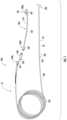
- FIG. 1is a top perspective view of cooperating components of a medical intrabody fluid transfer system, including a cannula assembly and an extension tube according to embodiments of the present invention.
- FIG. 2is a top view of an example cannula assembly for the medical intrabody fluid transfer system shown in FIG. 1 according to embodiments of the present invention.
- FIG. 3is a schematic illustration of a medical intrabody fluid transfer system operable in an image guided surgical navigation system according to embodiments of the present invention.
- FIG. 4is an enlarged partial section view of an example cannula of the cannula assembly shown in FIGS. 1 and 2 , held by a trajectory guide for intrabody placement of a needle tip of the cannula assembly, according to embodiments of the present invention.
- FIG. 5is a top view of an example extension tube according to embodiments of the present invention.
- FIG. 6is a section view taken along line 6 - 6 in FIG. 5 .
- FIG. 7is an enlarged view of detail B shown in FIG. 6 .
- FIG. 8is an enlarged view of detail C shown in FIG. 6 .
- FIG. 9is a top perspective unassembled view of portions of cooperating components of the intrabody fluid transfer system according to embodiments of the present invention.
- FIG. 10is a top assembled view of the components shown in FIG. 9 .
- FIG. 11is a top perspective assembled view of the assembly shown in FIG. 10 illustrating the flexible tubing and cannula of the intrabody fluid transfer system and a portion of the flexible tubing coupled to the cannula according to embodiments of the present invention.
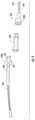
- FIG. 12is a side perspective, partial view of the extension tube held by a syringe pump body and coupled to a syringe for fluid transfer according to embodiments of the present invention.
- FIG. 13is a flow chart of exemplary actions that can be carried out according to embodiments of the present invention.
- spatially relative termssuch as “under,” “below,” “lower,” “over,” “upper” and the like, may be used herein for ease of description to describe one element or feature's relationship to another element(s) or feature(s) as illustrated in the figures. It will be understood that the spatially relative terms are intended to encompass different orientations of the device in use or operation in addition to the orientation depicted in the figures. For example, if the device in the figures is inverted, elements described as “under” or “beneath” other elements or features would then be oriented “over” the other elements or features. Thus, the exemplary term “under” can encompass both an orientation of “over” and “under”.
- the devicemay be otherwise oriented (rotated 90 degrees or at other orientations) and the spatially relative descriptors used herein interpreted accordingly.
- the terms “upwardly,” “downwardly,” “vertical,” “horizontal” and the likeare used herein for the purpose of explanation only unless specifically indicated otherwise.
- the term “monolithic”means that the component (e.g., inner tube or needle) is formed of a single uniform material.
- MRI visiblemeans that a device is visible, directly or indirectly, in an MRI image.
- the visibilitymay be indicated by the increased SNR of the MM signal proximate to the device (the device can act as an MRI receive antenna to collect signal from local tissue) and/or that the device actually generates MRI signal itself, such as via suitable hydro-based coatings and/or fluid (typically aqueous solutions) filled channels or lumens.
- MRI compatiblemeans that a device is safe for use in an MM environment and/or can operate as intended in an MRI environment without generating MR signal artifacts and, as such, if residing within the high-field strength region of the magnetic field, is typically made of a non-ferromagnetic MM compatible material(s) suitable to reside and/or operate in a high magnetic field environment.
- high-magnetic fieldrefers to field strengths above about 0.5 T (Tesla), typically above 1.0 T, and more typically between about 1.5 T and 10 T.
- the term “near real time”refers to both low latency and high frame rate. Latency is generally measured as the time from when an event occurs to display of the event (total processing time). For tracking, the frame rate can range from between about 100 fps to the imaging frame rate. In some embodiments, the tracking is updated at the imaging frame rate. For near “real-time” imaging, the frame rate is typically between about 1 fps to about 20 fps, and in some embodiments, between about 3 fps to about 7 fps. The low latency required to be considered “near real time” is generally less than or equal to about 1 second.
- the latency for tracking informationis about 0.01 s, and typically between about 0.25-0.5 s when interleaved with imaging data.
- visualizations with the location, orientation and/or configuration of a known intrabody devicecan be updated with low latency between about 1 fps to about 100 fps.
- visualizations using near real time MR image datacan be presented with a low latency, typically within between about 0.01 ms to less than about 1 second, and with a frame rate that is typically between about 1-20 fps.
- the systemcan use the tracking signal and image signal data to dynamically present anatomy and one or more intrabody devices in the visualization in near real-time.
- the tracking signal datais obtained and the associated spatial coordinates are determined while the MR image data is obtained and the resultant visualization(s) with the intrabody device (e.g., stylet) and the near RT MR image(s) are generated.
- sterilemeans that a device, kit, and/or packaging meets or exceeds U.S./Federal Drug Administration and/or other regulatory medical/surgical cleanliness guidelines, and typically is free from live bacteria or other microorganisms.
- Embodiments of the present inventioncan be utilized with various diagnostic or interventional devices and/or therapies to any desired internal region of an object using any suitable imaging modality, typically an MRI and/or in an MRI scanner or MM interventional suite.
- CT or other imaging modalitiesmay be used.
- the objectcan be any object, and may be particularly suitable for animal and/or human subjects for e.g., animal studies and/or veterinarian or human treatments.
- Some embodimentsdeliver therapies to the spine.
- Some embodimentsdeliver therapies to treat or stimulate a desired region of the sympathetic nerve chain.
- Other uses, inside or outside the brain, nervous system or spinal cordinclude stem cell placement, gene therapy or drug delivery for treating physiological conditions, chemotherapy, drugs including replicating therapy drugs.
- Some embodimentscan be used to treat tumors.
- the term “substance,” as used herein,refers to a liquid for treating or facilitating diagnosis of a condition and can include bions, stem cells or other target cells to site-specific regions in the body, such as neurological, nerves or other target sites and the like.
- stem cells and/or other rebuilding cells or productscan be delivered into spine, brain or cardiac tissue, such as a heart wall via a minimally invasive MRI guided procedure, while the heart is beating (i.e., not requiring a non-beating heart with the patient on a heart-lung machine). Examples of known stimulation treatments and/or target body regions are described in U.S. Pat. Nos.
- fluidwith respect to fluid being withdrawn from a subject refers to soft tissue, foreign matter, biological matter including cellular material and liquid in a subject.
- fusionand derivatives thereof refers to the delivery of a substance (which can be a single substance or a mixture) at a relatively slow rate so that the substance can infuse about a target region.
- infusaterefers to a substance so delivered.
- semi-rigidrefers to devices that have sufficient rigidity to have a self-supporting fixed shape (typically straight tubular or cylindrical shapes) in the absence of applied bending forces but have sufficient flexibility to be able to bend or deflect without breaking in response to forces applied during insertion into or removal from a trajectory guide (see, for example, 1250 t , FIG. 4 ), then return to its original self-supporting shape upon removal of the applied force(s).
- a self-supporting fixed shapetypically straight tubular or cylindrical shapes
- a trajectory guidesee, for example, 1250 t , FIG. 4
- flexiblemeans that the device(s) does not have sufficient rigidity to have a fixed shape without support and can be rolled, coiled, folded for example.
- the subjectcan be any subject, and may be particularly suitable for animal and/or human subjects for e.g., animal studies and/or veterinarian or human treatments.
- aspirate fluid from a target intrabody regionsuch as, for example, a brain.
- a target structurecan debulk it. Debulking the structure can relieve pressure on the surrounding areas. This can be desirable as it can be performed in a less invasive manner than surgical resection. See, U.S. patent application Ser. No. 16/217,222, the contents of which are hereby incorporated by reference as if recited in full herein.
- Embodiments of the inventioncan deliver therapies to the spine.
- Embodiments of the inventioncan deliver therapies to treat or stimulate a desired region of the sympathetic nerve chain.
- Other uses, inside or outside the brain, nervous system or spinal cord,include stem cell placement, gene therapy or drug delivery for treating physiological conditions, chemotherapy, drugs including replicating therapy drugs.
- Some embodimentscan be used to treat a patient with one or more tumors.
- FIG. 1illustrates an exemplary intrabody fluid transfer assembly 10 with a cannula assembly 300 .
- the cannula assembly 300is coupled to an extension tube assembly 500 comprising an external support tube 510 and a longitudinally extending inner tube 530 of increased rigidity and a different material.
- the external support tube 510can be polymeric flexible tubing.
- the cannula assembly 300comprises a length of flexible tubing 240 with longitudinally opposing proximal and distal end portions 240 p , 240 d , respectively.
- the distal end portion 240 dis coupled to a tubular cannula 20 that has increased rigidity relative to the flexible tubing 240 .
- An inner tube 230extends through the flexible tubing 240 and an inner tube 30 also extends through the tubular cannula 20 .
- the proximal end portion 240 p of the flexible tubing 240can comprise an external tab 241 and a connector 242 , such as a luer connector.
- an in-line filter 600can extend between the proximal end portion 240 p of the flexible tubing 240 and the distal end portion 500 d of the extension tube assembly 500 .
- the filter 600can sealably couple to connectors 242 , 502 .
- the inner tube 30can extend outside the proximal end 20 p and the distal end 20 d of the tubular cannula 20 .
- the extension tube assembly 500can have opposing proximal and distal end portions 500 p , 500 d , respectively. As will be discussed further below, the extension tube assembly 500 can have a longitudinally extending inner tube 530 and a connector 502 on the distal end portion 500 d and a connector 505 on the proximal end portion 500 p . The extension tube assembly 500 can have at least one external tab 507 , shown as adjacent the proximal end portion 500 p.
- the inner tube 230can be aligned with and couple to the inner tube 30 in the tubular cannula 20 and to the inner tube 530 in the extension tube assembly 500 .
- the inner tube 230 in the flexible tubing 240can be provided as a separate tube from the inner tube 30 that extends through the tubular cannula 20 . If provided as separate tubes 30 , 230 , the tubes 30 , 230 can have the same inner diameter, on average, and can be fluidly connected.
- the inner tube 30 of the tubular cannula 20 and the inner tube 230 in the flexible tubing 240can be a single unitary tube of continuous length and may have a constant inner diameter, at least over a major portion of a length thereof.
- the inner tube 230 in the flexible tubing 240can be one continuous piece of material, typically of either PEEK or fused silica glass, that goes from the distal end portion 240 d of the tubing 240 to a connector 160 at the proximal end portion 240 p .
- the connector 160can couple to connector 60 on the proximal end of the cannula 20 .
- the inner tube 230 and the flexible tubing 240have a length that is between about 4 feet to about 10 feet long.
- the extension tube assembly 500can have a length “L” that is less than that that of the flexible tubing 240 , typically 50% to 90% less than the length of the flexible tubing 240 .
- the extension tube assembly 500can have a length L that is about 2 feet to about 2 inches, including about 2 feet, about 1.5 feet, about 1 foot, about 11 inches, about 10 inches, about 9 inches, about 8 inches, about 7 inches, about 6 inches, about 5 inches, about 4 inches, about 3 inches and about 2 inches.
- the extension tube assembly 500can couple to the tubing 240 with the inner tube 230 which can couple to the inner tube 30 in the tubular cannula 20 .
- the extension tube assembly 500can reside closer to and couple directly to the pump P ( FIG. 3 ) or other pressurized source for delivery or vacuum.
- the inner tubes 30 , 230 , 530can be inner tubes of a small inner diameter defining a liquid flow channel.
- the small inner diametercan be in a range of range of 100 ⁇ m to about 750 ⁇ m, such as about 200 ⁇ m, or in a range of about 0.20 mm to about 0.05 mm, such as about 0.20 mm or about 0.053 mm.
- the inner tubes 30 , 230 , 530can be formed of PEEK or fused silica glass, or combinations thereof.
- the inner tubes 30 , 230 , 530can have the same size inner diameter at least over a major portion of a respective length of each tube 30 , 230 , 530 .
- Each tube 30 , 230 , 530can be axially aligned and coupled to be in fluid communication.
- the inner tube 530 in the extension tube assembly 500can reduce dead waste in the lumen when a delivery such as an infusion procedure is complete.
- the fused silica glass or PEEK or other material forming one or more of the inner tubes 30 , 230 , 530can be substantially, if not totally, inert and sterile, so as not to chemically interact with any fluid in the lumen.
- the inner tube 30 of the tubular cannula 20can define an external needle tip 30 t .
- the inner tube 30can release or intake fluid from a subject at a target intrabody site via an open channel extending through the inner tube 30 via a port at the tip 30 t.
- the cannula assembly 300can comprise concentric inner and outer tubes 30 , 33 that are coupled to and reside inside the tubular cannula 20 .
- the outer tube 33can have a lesser length than the inner tube 30 .
- the inner tube 30can reside a distance outside the tubular cannula 20 and the outer tube 33 can reside a distance outside the tubular cannula 20 but at a lesser distance than the inner tube 30 and terminate before the tip 30 t of the inner tube 30 .
- the inner tube 30 and the outer tube 33can have a fixed configuration and length relative to the tubular cannula 20 .
- the outer tube 33can be closely spaced to the inner surface 20 i of the outer wall 20 w of the tubular cannula 20 and the inner tube 30 can be closely space to the inner surface 30 i of the wall 33 w of the outer tube 33 to inhibit reverse flow and/or provide a fluid-resistant interface to inhibit flow therebetween.
- the outer tube 33can be affixed to the inner tube 30 and can have an interference fit with the tubular cannula 20 .
- one or all of the tubular cannula 20 , inner tube 30 and outer tube 33can be configured to extend and retract relative to each other and may include a length adjustment mechanism 40 as shown in FIGS. 2 and 4.
- the length adjustment mechanismcan be configured to adjust a distance or length between the distal end portion 20 d of the tubular cannula 20 and the exposed tip 30 t of the needle 30 .
- the length adjustment mechanismcan be configured to provide a maximal stroke length of between 0.5 inches and 3 inches, more typically between about 0.75 inches to about 1 inch (2.5 cm) such as about 0.79 inches.
- the length adjustmentcan be carried out in vivo while the housing remains external of a patient with the distal end 20 d of the cannula 20 and needle tip 30 t in the body of the patient.
- the tubular cannula 20 , the inner tube 30 and the outer tube 33can define a series of (typically between two-six) steps S of concentric changes (reduction in a direction toward the tip 30 t ) in outer diameter size between a distal end portion 20 d of the tubular cannula 20 and the tip 30 t of the inner tube 30 as shown in FIG. 2 .
- the steps Scan be configured to inhibit reflux.
- Each or one or more of the stepscan define a surface that is orthogonal to an outer wall 20 w of the tubular cannula 20 and/or a longitudinally extending tubular cannula body axis.
- the needle tip 30 tcan reside at a short distance from the distal end of the cannula 20 d such as in a range of about 1 mm to about 1.5 inches, typically between 1 mm and 1.1 inches.
- the flexible tubing 240 and the external support tube 510can be MM compatible.
- the external support tube 510 of the extension tube assembly 500can be of a different material and/or have a different configuration (wall thickness, etc.) than the flexible tubing 240 .
- the flexible tubing 240 and the support tube 510are both flexible PVC tubing.
- the flexible tubing 240 and the external support tube 510comprise silicone tubing.
- the tubular cannula 20can have a rigid body.
- the cannula 20may comprise alumina/ceramic that can be MM visible.
- the cannula 20can have an outer surface having a lubricious coating and/or sleeve 23 .
- the coating and/or sleevecan be a substantially transparent polymeric material. Where a sleeve is used, the sleeve 23 can be a thin flexible polymeric sleeve that can be conformably attached to the underlying cannula body.
- the coating and/or sleevecan be configured with sufficient strength to be able to retain components of the cannula should the cannula fracture.
- the sleevecan be an elastomeric shrink wrap or tube that can be heat-shrink applied to the underlying body.
- the tubular cannula 20can extend through a tubular support 260 of a trajectory guide 1250 t that can be held by a base or frame, e.g., a stereotactic frame that can be secured to the patient or that can be secured to a holder residing over the patient.
- a lock 170can be used to secure the tubular cannula 20 at a desired position in the tubular support 260 and the tubular cannula 20 with needle tip 30 t can extend into a patient to place the needle tip and a target region A and withdraw or delivery substance F. See, e.g., U.S. Pat. Nos.
- FIG. 3illustrates an MM-guided interventional system 100 with an MRI scanner 1220 , a clinician workstation 1230 with at least one circuit 1230 c , at least one display 1232 , an MRI compatible trajectory guide 1250 t and a fluid transfer assembly 10 .
- the fluid transfer assembly 10can cooperate with an infusion pump P which can be manual or automated and may include a syringe, or another pressurized delivery or vacuum source.
- the system 100can be configured to render or generate near real time or real time visualizations of the target anatomical space using MRI image data and predefined data of at least one surgical tool (e.g., tubular cannula 20 and/or trajectory guide 1250 t ) to segment the image data and place the trajectory guide 1250 t and the cannula 20 in the rendered visualization in the correct orientation and position in 3D space (which is the MM surgical space for MRI embodiments), anatomically registered to a patient.
- the trajectory guide 1250 t and the cannula 20can include or cooperate with tracking, monitoring and/or other interventional components.
- An exemplary trajectory guide 1250 tis illustrated in FIG. 3 in an exemplary (head) position on a patient.
- the trajectory guidecan be used for any target location including, for example, the spine.
- the trajectory guide 1250 tcan be mounted over or on an object, e.g., patient or subject, so that the upper receiving tube/support column 260 ( FIG. 4 is oriented substantially perpendicular to the entry location (typically for spinal uses) or may be mounted to extend outward from the patient entry location at an angle.
- the trajectory guide 1250 tcan be configured to provide one or more of an X-Y adjustment and/or pitch and roll adjustment in order to accurately position the cannula 20 at a desired location within a patient.
- suitable trajectory guidessee U.S. Pat. No. 8,374,677, the contents of which are hereby incorporated by reference as if recited in full herein.
- other trajectory guide configurationsmay be used and embodiments of the invention are not limited by the examples of the trajectory guides herein.
- the systemsare configured to provide a substantially automated or semi-automated and relatively easy-to-use MRI-guided system with defined workflow steps and interactive visualizations.
- the systemsdefine and present workflow with discrete steps for finding target and entry point(s), guiding the alignment of the targeting cannula to a planned trajectory, monitoring the insertion of the tubular cannula 20 , and adjusting the (X-Y) position in cases where the placement needs to be corrected.
- the circuit or computer modulecan display data for scan plane center and angulation to be entered at the console.
- the workstation/circuitcan passively or actively communicate with the MR scanner.
- the systemcan also be configured to use functional patient data (e.g., fiber tracks, fMRI and the like) to help plan or refine a target surgical site and/or access path.
- the system 100may also include a decoupling/tuning circuit that allows the system to cooperate with an MRI scanner 1220 and filters and the like. See, e.g., U.S. Pat. Nos. 6,701,176; 6,904,307 and U.S. Patent Application Publication No. 2003/0050557, the contents of which are hereby incorporated by reference as if recited in full herein.
- the inner tube 530 of the extension tube assembly 500extends as a continuous tube defining an inner flow lumen through the support tube 510 and at least partially into the opposing distal and proximal connectors 502 , 505 coupled to respective opposing distal and proximal end portions 510 d , 510 p of the external support tube 510 .
- the proximal end portion 510 p of the external support tube 510terminates adjacent an inner facing end 505 i of the connector 505 while the proximal end 530 p of the inner tube extends into the connector 505 and terminates adjacent an outer facing end 505 e of the connector 505 .
- a coupling tube 525can optionally be used at the connector 505 and support tube 510 interface.
- the coupling tube 525can be concentric with and surround a small length of the inner tube 530 and can extend into the connector 505 and into the external support tube 510 a distance that is typically about 0.25 inches to about 2 inches to provide additional bonding surface area.
- the (inner) coupling tube 525can be in contact with or within about 1 mm from the outer surface of the inner tube 530 .
- An outer adapter sleeve 545can extend about an outer surface 510 o of the support tube 510 and an outer surface 505 o of the connector 505 and couple the proximal end 510 p of the support tube 510 and the inner facing end 505 i of the connector 505 .
- a gap space 532can extend (longitudinally and circumferentially) between the inner tube 530 and an inner surface 505 i of an outer wall 505 w of the connector 505 , surrounding the proximal end 530 p of the inner tube 530 .
- the connector 505can be a female luer lock connector.
- An annular gap space 535can extend (circumferentially and longitudinally) between the inner tube 530 and an inner surface 510 i of an outer wall 510 w of the support tube 510 .
- the coupling tube 525can extend axially a distance into the gap space 532 and gap space 535 .
- a portion of the gap space 535 facing the connector 505 and into which the coupling tube 525 residescan comprise a filler material 560 , typically a filler material that can be applied in liquid form and solidified into a solid, such as a semi-rigid or flexible solid, surrounding an outer surface of the inner tube 530 .
- the filler material 560can comprise epoxy and/or one or more different formulations of LOCTITE adhesive and/or mixtures thereof.
- LOCTITE UV adhesive 3311 and LOCTITE adhesive 4010An outer facing portion of the gap space 532 in the connector 505 can remain open and surrounded by air.
- An inner facing portion of the gap space 535 in the support tube 510can remain open and surrounded by air or gas.
- the open inner facing portion of the gap space 535can extend over at least a major length of the support tube 510 , shown in FIG. 6 as an open annular gap space extending continuously between opposing end proximal and distal end portions 510 p , 510 d of the support tube 510 .
- FIG. 7illustrates that the filler material 560 resides in the gap space 535 a small distance D, typically a distance D in a range of about 0.24 inches and about 1 inch.
- FIG. 8illustrates that the distal end portion 510 d of the support tube 510 is coupled to a connector 502 .
- the distal end portion 510 d of the support tube 510can have an annular gap space 535 that can extend (circumferentially and longitudinally) between the inner tube 530 and an inner surface 510 i of an outer wall 510 w of the support tube 510 .
- Filler material 560can reside in the gap space 535 a sub-length of the annular space, such as a small distance D, typically a distance D in a range of about 0.24 inches and about 1 inch.
- the filler material 560can comprise epoxy that bonds components together at the distal and proximal end portions of the support tube 510 .
- the filler materialcan wick into the annular space 535 up to about an inch at both ends 510 p , 510 d of the support tube 510 .
- the filler material 560can create a good bond and also act as a strain relief so that the connector 502 and/or 505 does not kink in that region (stiff connection of respective luer fitting) and inhibits breakage of the inner tube 530 .
- the connector 502can have a primary body 502 b with an outer wall 502 w surrounding an axially projecting member 512 that extends a longitudinal distance beyond the outer wall 502 w .
- the connector 502has an inner channel 502 c which holds a segment of the outer support tube 510 .
- the connector 502can be a male luer lock connector.
- the inner tube 530extends through the projecting member 512 to terminate flush or adjacent an outer facing end 512 e of the projecting member 512 .
- Filler material 560can extend about and surround the inner tube inside the projecting member 512 .
- the filler material 560can occupy all the space between the inner tube 530 and the internal cavity 512 c of the projecting member 512 .
- the connector 502can have an open gap space 514 surrounding the projecting member 512 between the projecting member 512 and the outer wall 502 w.
- FIG. 9illustrates a proximal end 240 p of the flexible tubing 240 with the connector 242 aligned with an optional filter 600 and with the connector 502 on the distal end portion 500 p of the extension tube assembly 500 .
- FIG. 10illustrates these components sealably coupled together placing the tubes 530 , 230 and 30 in fluid communication.
- FIG. 11illustrates the intrabody fluid transfer assembly 10 assembled without the use of the filter 600 .
- FIG. 12illustrates the extension tube assembly 500 held by a housing 700 of a pump P placing the proximal end portion of the extension tube assembly adjacent a syringe 710 .
- the connector 505can directly engage a dispensing port 710 d of the syringe 710 thereby placing inner tube 530 against a tip of the syringe dispensing port 710 d .
- the housing 700can include attachment members 715 that slidably and detachable receive a segment of the extension tube assembly 500 .
- the assembly 10can be configured to flowably introduce, infuse and/or inject a desired therapy substance (e.g., antigen, gene therapy, chemotherapy or stem-cell or other therapy type).
- a desired therapy substancee.g., antigen, gene therapy, chemotherapy or stem-cell or other therapy type.
- the intrabody fluid transfer assembly 10is configured to deliver a drug therapy to the brain.
- the drug therapycan comprise substance F ( FIG. 4 15 ) delivered to the target site or region A through the inner tube 30 and may be any suitable and desired substance for drug discovery, animal or human clinical trials and/or approved medical procedures.
- the substance Fis a liquid or slurry.
- the substancemay be a chemotherapeutic (cytotoxic) fluid.
- the substancecan include certain types of advantageous cells that act as vaccines or other medicaments (for example, antigen presenting cells such as dendritic cells).
- the dendritic cellsmay be pulsed with one or more antigens and/or with RNA encoding one or more antigen.
- antigensare tumor-specific or pathogen-specific antigens.
- tumor-specific antigensinclude, but are not limited to, antigens from tumors such as renal cell tumors, melanoma, leukemia, myeloma, breast cancer, prostate cancer, ovarian cancer, lung cancer and bladder cancer.
- pathogen-specific antigensinclude, but are not limited to, antigens specific for HIV or HCV.
- the substance Fmay comprise radioactive material such as radioactive seeds.
- Substances F delivered to a target area in accordance with embodiments of the present inventionmay include, but are not limited to, the following drugs (including any combinations thereof) listed in Table 1:
- the intrabody fluid transfer system 10can be configured as an infusate delivery system that is delivered to a patient at an infusion rate in the range of from about 1 to about 3 ⁇ L/minute.
- Insertion of the surgical tubular cannula 20can be tracked in near real time by reference to a void in the patient tissue caused by the cannula 20 and reflected in the MR image.
- one or more MRI-visible fiducial markersmay be provided on the surgical tubular cannula 20 , MR scanned and processed, and displayed on the UI.
- the surgical cannula 20may itself be formed of an MM-visible material, MR scanned and processed, and displayed on the UI.
- the surgical cannula 20may include an embedded intrabody MRI antenna (not shown) that is configured to pick-up MRI signals in local tissue during an MRI procedure.
- the MM antennacan be configured to reside on a distal end portion of the surgical cannula.
- the antennahas a focal length or signal-receiving length of between about 1 cm to about 5 cm, and typically is configured to have a viewing length to receive MRI signals from local tissue of between about 1-2.5 cm.
- the MRI antennacan be formed as comprising a coaxial and/or triaxial antenna. However, other antenna configurations can be used, such as, for example, a whip antenna, a coil antenna, a loopless antenna, and/or a looped antenna.
- the devicescan be used to withdraw and/or aspirate a substance (e.g., spinal fluid, cardiac fluid or neuro fluid) from a patient.
- a substancee.g., spinal fluid, cardiac fluid or neuro fluid
- the devices and methods as disclosed hereincan be used to transfer a substance into and/or from a patient.
- the deviceshave been described herein primarily with reference to MRI-guided insertion and infusion procedures, in some embodiments the devices can be used in procedures without MRI guidance, such as using other imaging modalities where image-guided surgical navigation is desired.
- the intrabody fluid transfer system 10has been described with the surgical tubular cannula 20 coupled to a trajectory guide 1250 t , the cannula 20 may be used with other types of trajectory guidance or stereotactic frames or without a stereotactic frame or trajectory guide.
- extension tube assembly 500has been described for use with the cannula assembly 300 having the flexible tubing 240 with the inner tube 230 , it is contemplated that the extension tube assembly 500 can have sufficient length to directly couple to the connector 60 ( FIG. 2 ) at the distal end portion of the cannula 20 without requiring the intermediate flexible tubing 240 and inner tube 230 .
- FIG. 13is a flow chart of exemplary actions that can be carried out according to embodiments of the present invention.
- An extension tube assembly with a flexible outer tube surrounding an inner tubeis provided (block 800 ).
- a cannula assembly comprising a flexible outer tube surrounding an inner tubeis also provided (block 805 ).
- the cannula assemblyis coupled to the extension tube assembly so that the inner tubes of each are axially aligned (block 810 ).
- a proximal end portion of the extension tube assemblyis coupled to a syringe (block 815 ), typically via a luer connector on the extension tube assembly coupled directly to a dispensing end of the syringe. Substance is transferred from or to the syringe, through the inner tubes from or to a target intrabody location (block 820 ).
- the inner tubesare of a small inner diameter, optionally fused silica glass or PEEK inner tubes (block 813 ).
- a rigid or semi-rigid cannula of the cannula assemblycan be placed into a trajectory guide to define an intrabody trajectory of the cannula to a target intrabody location (block 814 ).
- An imaging modalitycan be used, such as CT and/or MRI, to provide an image guided surgical procedure to define the intrabody trajectory (block 816 ).
- the target intrabody locationcan be the brain (block 824 ).
- the inner tube of the cannula assemblycan define an external needle tip and can be fixedly attached to an outer tube that defines an increased diameter outer wall segment a distance of about 1-5 mm, typically about 3 mm from the tip.
- the extension tube assembly and cannula assemblycan be an infusate ventricular delivery system for brain delivery of a target substance to a target anatomical region.
- the devicecan be configured to allow a single intrabody insertion of the cannula/inner tube thereof, to a target anatomical region in the brain (such as tissue generally in-line with and between the nose and back of the head and, starting dispensing/infusing from the back of the head while translating the distal end of the cannula/inner tube thereof frontward to treat a large volume through one intrabody insertion of the cannula/inner tube thereof.
Landscapes
- Health & Medical Sciences (AREA)
- Life Sciences & Earth Sciences (AREA)
- Heart & Thoracic Surgery (AREA)
- Animal Behavior & Ethology (AREA)
- Veterinary Medicine (AREA)
- Public Health (AREA)
- Engineering & Computer Science (AREA)
- Biomedical Technology (AREA)
- General Health & Medical Sciences (AREA)
- Anesthesiology (AREA)
- Hematology (AREA)
- Pulmonology (AREA)
- Biophysics (AREA)
- Surgery (AREA)
- Nuclear Medicine, Radiotherapy & Molecular Imaging (AREA)
- Oral & Maxillofacial Surgery (AREA)
- Pathology (AREA)
- Medical Informatics (AREA)
- Molecular Biology (AREA)
- Infusion, Injection, And Reservoir Apparatuses (AREA)
Abstract
Description
| TABLE 1 | |
| DRUG (generic name) | DISORDER(S) |
| Caprylidene | Alzheimer's disease |
| Donepezil | Alzheimer's disease |
| Galantamine | Alzheimer's disease |
| Memantine | Alzheimer's disease |
| Tacrine | Alzheimer's disease |
| vitamin E | Alzheimer's disease |
| ergoloid mesylates | Alzheimer's disease |
| Riluzole | Amyotrophic lateral sclerosis |
| Metoprolol | Benign essential tremors |
| Primidone | Benign essential tremors |
| Propanolol | Benign essential tremors |
| Gabapentin | Benign essential tremors & Epilepsy |
| Nadolol | Benign essential tremors & Parkinson's disease |
| Zonisamide | Benign essential tremors & Parkinson's disease |
| Carmustine | Brain tumor |
| Lomustine | Brain tumor |
| Methotrexate | Brain tumor |
| Cisplatin | Brain tumor & Neuroblastoma |
| Ioversol | Cerebral arteriography |
| Mannitol | Cerebral Edema |
| Dexamethasone | Cerebral Edema & Neurosarcoidosis |
| Baclofen | Cerebral spasticity |
| Ticlopidine | Cerebral thrombosis/embolism |
| Isoxsuprine | Cerebrovascular insufficiency |
| Cefotaxime | CNS infection & Meningitis |
| Acyclovir | Encephalitis |
| Foscamet | Encephalitis |
| Ganciclovir | Encephalitis |
| interferon alpha-2a | Encephalitis |
| Carbamazepine | Epilepsy |
| Clonazepam | Epilepsy |
| Diazepam | Epilepsy |
| divalproex sodium | Epilepsy |
| Ethosuximide | Epilepsy |
| Ethotoin | Epilepsy |
| Felbamate | Epilepsy |
| Fosphenytoin | Epilepsy |
| Levetiracetam | Epilepsy |
| Mephobarbital | Epilepsy |
| Paramethadione | Epilepsy |
| Phenytoin | Epilepsy |
| Trimethadione | Epilepsy |
| Pregabalin | Epilepsy & Neuralgia |
| immune globulin intravenous | Guillain-Barre Syndrome |
| interferon beta-1b | Guillain-Barre Syndrome & Multiple sclerosis |
| Azathioprine | Guillain-Barre Syndrome & Multiple sclerosis & |
| Neurosarcoidosis | |
| Risperidone | Head injury |
| Tetrabenazine | Huntington's disease |
| Acetazolamide | Hydrocephalus & Epilepsy |
| Alteplase | Ischemic stroke |
| Clopidogrel | Ischemic stroke |
| Nimodipine | Ischemic stroke & Subarachnoid hemorrhage |
| Aspirin | Ischemic stroke & Thromboembolic stroke |
| Amikacin | Encaphalitis |
| Ampicillin | Encaphalitis |
| ampicillin/sulbactam | Encaphalitis |
| Ceftazidime | Encaphalitis |
| Ceftizoxime | Encaphalitis |
| Cefuroxime | Encaphalitis |
| Chloramphenicol | Encaphalitis |
| cilastatin/imipenem | Encaphalitis |
| Gentamicin | Encaphalitis |
| Meropenem | Encaphalitis |
| Metronidazole | Encaphalitis |
| Nafcillin | Encaphalitis |
| Oxacillin | Encaphalitis |
| Piperacillin | Encaphalitis |
| Rifampin | Encaphalitis |
| sulfamethoxazole/trimethoprim | Encaphalitis |
| Tobramycin | Encaphalitis |
| Triamcinolone | Encaphalitis |
| Vancomycin | Encaphalitis |
| Ceftriaxone | Encaphalitis & Neurosyphilis |
| Penicillin | Encaphalitis & Neurosyphilis |
| Corticotrophin | Multiple sclerosis |
| Dalfampridine | Multiple sclerosis |
| Glatiramer | Multiple sclerosis |
| Mitoxantrone | Multiple sclerosis |
| Natalizumab | Multiple sclerosis |
| Modafinil | Multiple sclerosis |
| Cyclophosphamide | Multiple sclerosis & Brain tumor & Neuroblastoma |
| interferon beta-1a | Multiple sclerosis & Neuritis |
| Prednisolone | Multiple sclerosis & Neurosarcoidosis |
| Prednisone | Multiple sclerosis & Neurosarcoidosis |
| Amantadine | Multiple sclerosis & Parkinson's disease |
| Methylprednisolone | Neuralgia |
| Desvenlafaxine | Neuralgia |
| Nortriptyline | Neuralgia |
| Doxorubicin | Neuroblastoma |
| Vincristine | Neuroblastoma |
| Albendazole | Neurocystecercosis |
| chloroquine phosphate | Neurosarcoidosis |
| Hydroxychloroquine | Neurosarcoidosis |
| Infliximab | Neurosarcoidosis |
| Pentoxyfilline | Neurosarcoidosis |
| Thalidomide | Neurosarcoidosis |
| Apomorphine | Parkinson's disease |
| Belladonna | Parkinson's disease |
| Benztropine | Parkinson's disease |
| Biperiden | Parkinson's disease |
| Bromocriptine | Parkinson's disease |
| Carbidopa | Parkinson's disease |
| carbidopa/entacapone/levodopa | Parkinson's disease |
| carbidopa/levodopa | Parkinson's disease |
| Entacapone | Parkinson's disease |
| Levodopa | Parkinson's disease |
| pergolide mesylate | Parkinson's disease |
| Pramipexole | Parkinson's disease |
| Procyclidine | Parkinson's disease |
| Rasagiline | Parkinson's disease |
| Ropinirole | Parkinson's disease |
| Rotiotine | Parkinson's disease |
| Scopolamine | Parkinson's disease |
| Tolcapone | Parkinson's disease |
| Trihexyphenidyl | Parkinson's disease |
| Seleginline | Parkinson's disease |
| Rivastigmine | Parkinson's disease & Alzheimer's disease |
| Anisindione | Thromboembolic stroke |
| Warfarin | Thromboembolic stroke |
| 5-hydroxytryptophan | Depression & Anxiety & ADHD |
| Duloxetine | Depression & Anxiety & Bipolar disorder |
| Escitalopram | Depression & Anxiety & Bipolar disorder |
| Venlafaxine | Depression & Anxiety & Bipolar disorder & Autism & |
| Social anxiety disorder | |
| Desvenlafaxine | Depression & Anxiety & PTSD & ADHD |
| Paroxetine | Depression & Anxiety & PTSD & Social anxiety disorder |
| fluoxetine/olanzapine | Depression & Bipolar disorder |
| 1-methylfolate | Depression & BPD |
| Amitriptyline | Depression & PTSD |
| Sertraline | Depression & PTSD & Bipolar disorder & Social anxiety |
| disorder | |
| Fluvoxamine | Depression & PTSD & Social anxiety disorder |
| Olanzapine | Depression & Schizophrenia & Bipolar disorder |
| Paliperidone | Depression & Schizophrenia & Bipolar disorder |
| Aripiprazole | Depression & Schizophrenia & Bipolar disorder & Autism |
| Quetiapine | Depression & Schizophrenia & PTSD & BPD & Bipolar |
| disorder | |
| Risperidone | Depression & Schizophrenia & PTSD & BPD & Bipolar |
| disorder & Autism | |
| Amisulpride | Depression & Social anxiety disorder |
| Chlorpromazine | Psychosis |
| Droperidol | Psychosis |
| Fluphenazine | Psychosis |
| Periciazine | Psychosis |
| Perphenazine | Psychosis |
| Thiothixene | Psychosis |
| Triflupromazine | Psychosis |
| Haloperidol | Psychosis & Dementia |
| Prazosin | PTSD |
| Clozapine | Schizophrenia |
| Flupenthixol | Schizophrenia |
| Iloperidone | Schizophrenia |
| Loxapine | Schizophrenia |
| Mesoridazine | Schizophrenia |
| Promazine | Schizophrenia |
| Reserpine | Schizophrenia |
| Thioridazein | Schizophrenia |
| Zuclopenthixol | Schizophrenia |
| Asenapine | Schizophrenia & Bipolar disorder |
| Levomepromazine | Schizophrenia & Bipolar disorder |
| Ziprasidone | Schizophrenia & Bipolar disorder |
| Molindone | Schizophrenia & Psychosis |
| Pimozide | Schizophrenia & Psychosis |
| Thioridazine | Schizophrenia & Psychosis |
| Cytarabine | Chemotherapy, hematological malignancies |
Claims (14)
Priority Applications (4)
| Application Number | Priority Date | Filing Date | Title |
|---|---|---|---|
| US16/887,161US11684750B2 (en) | 2019-10-08 | 2020-05-29 | Extension tube assembly and related medical fluid transfer systems and methods |
| PCT/US2020/036741WO2021071561A1 (en) | 2019-10-08 | 2020-06-09 | Extension tube assembly and related medical fluid transfer systems and methods |
| EP20750495.2AEP3993864B1 (en) | 2019-10-08 | 2020-06-09 | Extension tube assembly and related medical fluid transfer systems and methods |
| US18/312,674US12290643B2 (en) | 2019-10-08 | 2023-05-05 | Extension tube assembly and related medical fluid transfer systems and methods |
Applications Claiming Priority (3)
| Application Number | Priority Date | Filing Date | Title |
|---|---|---|---|
| US201962912324P | 2019-10-08 | 2019-10-08 | |
| US201962937911P | 2019-11-20 | 2019-11-20 | |
| US16/887,161US11684750B2 (en) | 2019-10-08 | 2020-05-29 | Extension tube assembly and related medical fluid transfer systems and methods |
Related Child Applications (1)
| Application Number | Title | Priority Date | Filing Date |
|---|---|---|---|
| US18/312,674ContinuationUS12290643B2 (en) | 2019-10-08 | 2023-05-05 | Extension tube assembly and related medical fluid transfer systems and methods |
Publications (2)
| Publication Number | Publication Date |
|---|---|
| US20210100977A1 US20210100977A1 (en) | 2021-04-08 |
| US11684750B2true US11684750B2 (en) | 2023-06-27 |
Family
ID=75273817
Family Applications (2)
| Application Number | Title | Priority Date | Filing Date |
|---|---|---|---|
| US16/887,161Active2041-07-03US11684750B2 (en) | 2019-10-08 | 2020-05-29 | Extension tube assembly and related medical fluid transfer systems and methods |
| US18/312,674ActiveUS12290643B2 (en) | 2019-10-08 | 2023-05-05 | Extension tube assembly and related medical fluid transfer systems and methods |
Family Applications After (1)
| Application Number | Title | Priority Date | Filing Date |
|---|---|---|---|
| US18/312,674ActiveUS12290643B2 (en) | 2019-10-08 | 2023-05-05 | Extension tube assembly and related medical fluid transfer systems and methods |
Country Status (3)
| Country | Link |
|---|---|
| US (2) | US11684750B2 (en) |
| EP (1) | EP3993864B1 (en) |
| WO (1) | WO2021071561A1 (en) |
Families Citing this family (3)
| Publication number | Priority date | Publication date | Assignee | Title |
|---|---|---|---|---|
| US10105485B2 (en) | 2010-04-16 | 2018-10-23 | MRI Interventions, Inc. | MRI surgical systems including MRI-compatible surgical cannulae for transferring a substance to and/or from a patient |
| EP3393571B1 (en) | 2016-02-17 | 2024-03-06 | ClearPoint Neuro, Inc. | Intrabody surgical fluid transfer assemblies with adjustable exposed cannula to needle tip length, related systems and methods |
| EP4565135A1 (en)* | 2022-09-08 | 2025-06-11 | CareFusion 303, Inc. | Hemolysis-reduction extension set for direct blood draw |
Citations (171)
| Publication number | Priority date | Publication date | Assignee | Title |
|---|---|---|---|---|
| US3352306A (en) | 1963-12-23 | 1967-11-14 | Hrisch Sidney | Intravenous catheter assembly |
| US3540447A (en) | 1967-09-29 | 1970-11-17 | Becton Dickinson Co | Spinal needle |
| GB1255551A (en) | 1968-03-30 | 1971-12-01 | Heraeus Schott Quarzschmelze | Improvements in or relating to externally coated fused silica tube |
| US3824157A (en) | 1971-01-29 | 1974-07-16 | Gen Electric | Method of equilibrating and calibrating a partial pressure gas sensor |
| US3856009A (en) | 1971-11-26 | 1974-12-24 | Johnson & Johnson | Catheter placement unit |
| US4149535A (en) | 1976-05-06 | 1979-04-17 | Gist-Brocades N.V. | Catheter holding device |
| US4239042A (en) | 1979-04-05 | 1980-12-16 | Dow Corning K.K. | Catheter placement system |
| US4265928A (en) | 1978-10-06 | 1981-05-05 | Intermedicat Gmbh | Anti-thrombogenic retentive catheter |
| US4327722A (en) | 1979-08-20 | 1982-05-04 | Groshong Leroy E | Methods and apparatus for intravenous therapy and hyperalimentation |
| US4449532A (en) | 1980-07-08 | 1984-05-22 | Karl Storz | Dilator to facilitate endoscope insertion into the body |
| US4531943A (en) | 1983-08-08 | 1985-07-30 | Angiomedics Corporation | Catheter with soft deformable tip |
| US4543092A (en) | 1982-08-06 | 1985-09-24 | Doron Mehler | Catheter set |
| US4543091A (en) | 1983-05-18 | 1985-09-24 | Edward C. Froning | X-ray marker device |
| US4597421A (en) | 1984-11-19 | 1986-07-01 | Varian Associates, Inc. | Method and device for on-column injection of a liquid sample into small diameter columns |
| US4623789A (en) | 1983-03-10 | 1986-11-18 | Shionogi & Co., Ltd. | Fiberoptic probe for brain scanning with detachable cannula guide |
| US4629450A (en) | 1984-05-09 | 1986-12-16 | Terumo Corporation | Catheter introducing instrument |
| US4705511A (en) | 1985-05-13 | 1987-11-10 | Bipore, Inc. | Introducer sheath assembly |
| US4738658A (en) | 1986-09-19 | 1988-04-19 | Aries Medical Incorporated | Tapered hemostatic device for use in conjunction with a catheter for alleviating blood leakage and method for using same |
| US4739768A (en) | 1986-06-02 | 1988-04-26 | Target Therapeutics | Catheter for guide-wire tracking |
| US4781691A (en) | 1987-07-17 | 1988-11-01 | The Kendall Company | Stepped needle |
| US4820349A (en) | 1987-08-21 | 1989-04-11 | C. R. Bard, Inc. | Dilatation catheter with collapsible outer diameter |
| US4846799A (en) | 1986-10-09 | 1989-07-11 | Hakko Electric Machine Works Co., Ltd. | Set of double needles for injecting liquid medicine |
| US4897077A (en) | 1987-05-22 | 1990-01-30 | Kontron Inc. | Method of inserting an IAB device into the body |
| US4955863A (en) | 1986-02-05 | 1990-09-11 | Menlo Care, Inc. | Adjustable catheter assembly |
| US4978334A (en) | 1988-09-08 | 1990-12-18 | Toye Frederic J | Apparatus and method for providing passage into body viscus |
| US4995866A (en) | 1989-12-15 | 1991-02-26 | Microvena Corporation | Combined needle and dilator apparatus |
| US5069673A (en) | 1990-02-07 | 1991-12-03 | Cordis Corporation | Catheter with double step-down bore |
| US5380292A (en) | 1993-12-22 | 1995-01-10 | Wilson-Cook Medical, Inc. | Gastrointestinal needle mechanism |
| US5562626A (en) | 1995-09-11 | 1996-10-08 | Sanpietro; Joseph A. | Safety syringe |
| US5699801A (en) | 1995-06-01 | 1997-12-23 | The Johns Hopkins University | Method of internal magnetic resonance imaging and spectroscopic analysis and associated apparatus |
| US5720720A (en) | 1993-08-27 | 1998-02-24 | The United States Of America As Represented By The Department Of Health And Human Services | Convection-enhanced drug delivery |
| US5722985A (en) | 1996-12-27 | 1998-03-03 | Pettus; William G. | Instrument for tumor therapy |
| US5792144A (en) | 1997-03-31 | 1998-08-11 | Cathco, Inc. | Stent delivery catheter system |
| US5833662A (en) | 1995-01-19 | 1998-11-10 | Stevens; Robert C. | Hemostasis cannula system |
| US5851203A (en) | 1993-09-22 | 1998-12-22 | Cordis Corporation | Neuro-microcatheter |
| US5857999A (en) | 1995-05-05 | 1999-01-12 | Imagyn Medical Technologies, Inc. | Small diameter introducer for laparoscopic instruments |
| WO1999004849A1 (en) | 1997-07-25 | 1999-02-04 | The Regents Of The University Of California | Retroperfusion catheter apparatus and method |
| US5871470A (en) | 1997-04-18 | 1999-02-16 | Becton Dickinson And Company | Combined spinal epidural needle set |
| US5902282A (en) | 1996-12-26 | 1999-05-11 | Johnson & Johnson Medical, Inc. | Step-down catheter |
| US5919171A (en) | 1994-08-03 | 1999-07-06 | Kanegafuchi Kagaku Kogyo Kabushiki Kaisha | Microcatheter |
| US5928145A (en) | 1996-04-25 | 1999-07-27 | The Johns Hopkins University | Method of magnetic resonance imaging and spectroscopic analysis and associated apparatus employing a loopless antenna |
| US5935122A (en) | 1991-12-13 | 1999-08-10 | Endovascular Technologies, Inc. | Dual valve, flexible expandable sheath and method |
| WO1999049909A2 (en) | 1998-03-27 | 1999-10-07 | Brigham & Women's Hospital, Inc. | Revascularization apparatus having coaxial channeling and injecting means |
| US6020196A (en) | 1996-05-09 | 2000-02-01 | Baxter International Inc. | Devices for harvesting and homogenizing adipose tissue containing autologous endothelial cells |
| US6026316A (en) | 1997-05-15 | 2000-02-15 | Regents Of The University Of Minnesota | Method and apparatus for use with MR imaging |
| US6030369A (en) | 1997-07-03 | 2000-02-29 | Target Therapeutics Inc. | Micro catheter shaft |
| US6042579A (en) | 1997-04-30 | 2000-03-28 | Medtronic, Inc. | Techniques for treating neurodegenerative disorders by infusion of nerve growth factors into the brain |
| US6050992A (en) | 1997-05-19 | 2000-04-18 | Radiotherapeutics Corporation | Apparatus and method for treating tissue with multiple electrodes |
| US6093180A (en) | 1995-04-28 | 2000-07-25 | Medtronic, Inc. | Intraparenchymal infusion catheter system |
| EP1029509A1 (en) | 1999-02-19 | 2000-08-23 | Magnetic Vision GmbH | Device for cutting and aspirating tissue |
| US6167311A (en) | 1999-06-14 | 2000-12-26 | Electro Core Techniques, Llc | Method of treating psychological disorders by brain stimulation within the thalamus |
| US6186986B1 (en) | 1998-01-21 | 2001-02-13 | St. Jude Medical Cardiovascular Group, Inc. | Micro-catheters and methods of their manufacture |
| US6231591B1 (en) | 1991-10-18 | 2001-05-15 | 2000 Injectx, Inc. | Method of localized fluid therapy |
| US6263229B1 (en) | 1998-11-13 | 2001-07-17 | Johns Hopkins University School Of Medicine | Miniature magnetic resonance catheter coils and related methods |
| US6284971B1 (en) | 1998-11-25 | 2001-09-04 | Johns Hopkins University School Of Medicine | Enhanced safety coaxial cables |
| USRE37410E1 (en) | 1994-08-02 | 2001-10-16 | Massachusetts Institute Of Technology | Controlled local delivery of chemotherapeutic agents for treating solid tumors |
| US6309634B1 (en) | 1998-05-27 | 2001-10-30 | Avigen, Inc. | Methods of treating Parkinson's disease using recombinant adeno-associated vector (rAAV) |
| US6336915B1 (en) | 1997-01-08 | 2002-01-08 | Symbiosis Corporation | Endoscopic infusion needle having dual distal stops |
| US6356786B1 (en) | 2000-01-20 | 2002-03-12 | Electrocore Techniques, Llc | Method of treating palmar hyperhydrosis by electrical stimulation of the sympathetic nervous chain |
| US20020052576A1 (en)* | 1999-07-19 | 2002-05-02 | Massengale Roger Dillard | Method of fluid delivery and catheters for use with same |
| US6405079B1 (en) | 2000-09-22 | 2002-06-11 | Mehdi M. Ansarinia | Stimulation method for the dural venous sinuses and adjacent dura for treatment of medical conditions |
| US20020087152A1 (en) | 2001-01-04 | 2002-07-04 | Endocare, Inc. | Systems and methods for delivering a probe into tissue |
| US20020091372A1 (en) | 2001-01-09 | 2002-07-11 | Andrew Cragg | Micro catheter and guidewire system having improved pushability and control |
| US20020095081A1 (en) | 1995-09-28 | 2002-07-18 | Brainlab Med. Computersysteme Gmbh | Neuro-navigation system |
| US6438423B1 (en) | 2000-01-20 | 2002-08-20 | Electrocore Technique, Llc | Method of treating complex regional pain syndromes by electrical stimulation of the sympathetic nerve chain |
| US20020114780A1 (en) | 2000-11-30 | 2002-08-22 | Krys Bankiewicz | Methods of increasing distribution of therapeutic agents |
| US6461296B1 (en) | 1998-06-26 | 2002-10-08 | 2000 Injectx, Inc. | Method and apparatus for delivery of genes, enzymes and biological agents to tissue cells |
| US20020183763A1 (en) | 2001-05-17 | 2002-12-05 | Callol Joseph R. | Stent and catheter assembly and method for treating bifurcations |
| US20030028095A1 (en) | 1999-04-15 | 2003-02-06 | Steve Tulley | Magnetic resonance imaging probe |
| US6526318B1 (en) | 2000-06-16 | 2003-02-25 | Mehdi M. Ansarinia | Stimulation method for the sphenopalatine ganglia, sphenopalatine nerve, or vidian nerve for treatment of medical conditions |
| US6524299B1 (en) | 1997-04-09 | 2003-02-25 | Target Therapeutics, Inc. | Flow-directed catheter |
| US20030050557A1 (en) | 1998-11-04 | 2003-03-13 | Susil Robert C. | Systems and methods for magnetic-resonance-guided interventional procedures |
| US6539263B1 (en) | 1999-06-11 | 2003-03-25 | Cornell Research Foundation, Inc. | Feedback mechanism for deep brain stimulation |
| US20030073934A1 (en) | 2001-10-17 | 2003-04-17 | David A. Putz | Double slotted-cannula device and method of use |
| US6551290B1 (en) | 2000-03-31 | 2003-04-22 | Medtronic, Inc. | Catheter for target specific drug delivery |
| US6585694B1 (en) | 2000-09-07 | 2003-07-01 | Syntheon, Llc | Knob-controlled endoscopic needle device |
| US20030130575A1 (en) | 1991-10-18 | 2003-07-10 | Ashvin Desai | Method and apparatus for tissue treatment with laser and electromagnetic radiation |
| US6606513B2 (en) | 2000-02-01 | 2003-08-12 | Surgi-Vision, Inc. | Magnetic resonance imaging transseptal needle antenna |
| EP1334740A1 (en) | 2002-02-11 | 2003-08-13 | Sergio Restelli | Glass safety syringe and relative safety kit for glass syringe |
| US6609030B1 (en) | 2000-02-24 | 2003-08-19 | Electrocore Techniques, Llc | Method of treating psychiatric diseases by neuromodulation within the dorsomedial thalamus |
| WO2003077785A1 (en) | 2002-03-12 | 2003-09-25 | Steven Streatfield Gill | Catheter and guide tube for intracerebral application |
| US6628980B2 (en) | 2000-03-24 | 2003-09-30 | Surgi-Vision, Inc. | Apparatus, systems, and methods for in vivo magnetic resonance imaging |
| US6641555B1 (en) | 1997-11-12 | 2003-11-04 | Mdc Investment Holdings, Inc. | Fluid collection device with captured retractable needle |
| US6641564B1 (en) | 2000-11-06 | 2003-11-04 | Medamicus, Inc. | Safety introducer apparatus and method therefor |
| US20030216714A1 (en) | 2002-04-30 | 2003-11-20 | Gill Steven Streatfield | Pump |
| US6675033B1 (en) | 1999-04-15 | 2004-01-06 | Johns Hopkins University School Of Medicine | Magnetic resonance imaging guidewire probe |
| US6689142B1 (en) | 1999-04-26 | 2004-02-10 | Scimed Life Systems, Inc. | Apparatus and methods for guiding a needle |
| US6701176B1 (en) | 1998-11-04 | 2004-03-02 | Johns Hopkins University School Of Medicine | Magnetic-resonance-guided imaging, electrophysiology, and ablation |
| US20040044329A1 (en) | 2002-08-29 | 2004-03-04 | Trudell Leonard A. | Catheter for cardiac injection and method for delivery of therapeutic agents to specified tissues |
| US20040046557A1 (en) | 2002-05-29 | 2004-03-11 | Parag Karmarkar | Magnetic resonance probes |
| US6708064B2 (en) | 2000-02-24 | 2004-03-16 | Ali R. Rezai | Modulation of the brain to affect psychiatric disorders |
| US20040064098A1 (en) | 2001-01-05 | 2004-04-01 | Alfred Cuschieri | Hypodermic needle and fluid injection device |
| US20040068190A1 (en) | 2002-10-04 | 2004-04-08 | Cespedes Eduardo Ignacio | Imaging catheter with indicia and methods of use |
| WO2004031348A2 (en) | 2002-09-24 | 2004-04-15 | The Government Of The United States Of America As Represented By The Secretary Of The Department Of Health And Human Services | Method for convection enhanced delivery of therapeutic agents |
| US20040092879A1 (en) | 2000-11-06 | 2004-05-13 | Medamicus, Inc. | Safety introducer apparatus and method therefor |
| JP2004147830A (en) | 2002-10-30 | 2004-05-27 | Jfe Steel Kk | Ceramic coated needle for gene control, method for producing the same, and apparatus for producing the same |
| US20040199129A1 (en) | 2003-04-07 | 2004-10-07 | Scimed Life Systems, Inc. | Vascular access port |
| US20040209810A1 (en) | 2003-02-24 | 2004-10-21 | Gill Steven S. | Method of treating Parkinson's disease in humans by intraputaminal infusion of glial cell-line derived neurotrophic factor |
| US20040215162A1 (en) | 2003-04-25 | 2004-10-28 | Ad-Tech Medical Instrument Corp. | Intracranial catheter assembly for precise treatment of brain tissue |
| US20040249261A1 (en)* | 2001-06-15 | 2004-12-09 | Torchia Mark G. | Hyperthermia treatment and probe therefor |
| EP1491154A1 (en) | 2002-01-22 | 2004-12-29 | JFE Steel Corporation | Ceramic-coated instruments for medical use, ceramic-coated instruments for studying living organisms and process for producing the same |
| US20050004504A1 (en) | 2003-06-24 | 2005-01-06 | Frye Mark R. | Catheter for extracorporeal treatment |
| US20050112065A1 (en) | 2003-07-09 | 2005-05-26 | Drummond Daryl C. | Remote detection of substance delivery to cells |
| US20050148865A1 (en) | 2001-11-09 | 2005-07-07 | Scimed Life Systems, Inc. | Ceramic reinforcement member for MRI devices |
| US20050256503A1 (en) | 2002-05-07 | 2005-11-17 | Cardiac Pacemakers, Inc. | Tapered catheter delivery system |
| US20060052750A1 (en) | 2004-09-09 | 2006-03-09 | Jay Lenker | Expandable transluminal sheath |
| US7037295B2 (en) | 1999-12-16 | 2006-05-02 | Advanced Cardiovascular Systems, Inc. | Co-extruded taper shaft |
| US20060129126A1 (en) | 2004-11-19 | 2006-06-15 | Kaplitt Michael G | Infusion device and method for infusing material into the brain of a patient |
| US20060135945A1 (en) | 2004-10-05 | 2006-06-22 | Avigen, Inc., The Regents Of The University Of California | Stepped cannula |
| US20060217664A1 (en) | 2004-11-15 | 2006-09-28 | Hattler Brack G | Telescoping vascular dilator |
| US7182944B2 (en) | 2001-04-25 | 2007-02-27 | The United States Of America As Represented By The Department Of Health And Human Services | Methods of increasing distribution of nucleic acids |
| US20070088295A1 (en) | 2005-08-23 | 2007-04-19 | Bankiewicz Krystof S | Reflux resistant cannula and system for chronic delivery of therapeutic agents using convection-enhanced delivery |
| US20070110798A1 (en) | 2004-05-03 | 2007-05-17 | Hermes Biosciences, Inc. | Liposomes useful for drug delivery to the brain |
| US20070167736A1 (en) | 2004-05-21 | 2007-07-19 | Dietz Timothy G | MRI biopsy apparatus incorporating an imageable penetrating portion |
| US20070179455A1 (en) | 2005-12-16 | 2007-08-02 | David Geliebter | Needle constructed with a transparent or translucent material |
| US20070250021A1 (en) | 2002-10-10 | 2007-10-25 | Becton, Dickinson And Company | System and method of delivering local anesthesia |
| US20070254842A1 (en) | 2006-04-25 | 2007-11-01 | The Regents Of The University Of California | Administration of growth factors for the treatment of cns disorders |
| US7329262B2 (en) | 2002-03-12 | 2008-02-12 | Renishaw Plc | Stereoguide for clamping neurosurgical instruments |
| WO2008020241A2 (en) | 2006-08-18 | 2008-02-21 | Renishaw Plc | Neurosurgical instruments |
| US20080103456A1 (en) | 2006-10-30 | 2008-05-01 | Johnson Benjamin A | Infusion catheter |
| US20080119821A1 (en) | 2006-11-17 | 2008-05-22 | Warsaw Orthopedic, Inc. | Multiport Cannula |
| US20080215008A1 (en) | 2006-12-20 | 2008-09-04 | Nance Edward J | Expandable trans-septal sheath |
| US20080228168A1 (en) | 2007-03-16 | 2008-09-18 | Stephan Mittermeyer | Catheter with changing material properties |
| WO2008144585A1 (en) | 2007-05-17 | 2008-11-27 | Medgenesis Therapeutix Inc. | Convection-enhanced delivery catheter with removable stiffening member and method for using same |
| WO2008144775A1 (en) | 2007-05-23 | 2008-11-27 | Biosense Webster, Inc. | Extension control handle with adjustable locking mechanism |
| US20080319377A1 (en) | 2004-05-04 | 2008-12-25 | James Keenan | Medical Device for Generating Transient Bubbles |
| WO2009042135A2 (en) | 2007-09-24 | 2009-04-02 | Surgivision, Inc. | Mri surgical systems for real-time visualizations using mri image data and predefined data of surgical tools |
| US20090088730A1 (en) | 2007-09-28 | 2009-04-02 | Codman & Shurtleff, Inc. | Catheter for reduced reflux in targeted tissue delivery of a therapeutic agent |
| US20090088695A1 (en) | 2007-09-28 | 2009-04-02 | Codman & Shurtleff, Inc. | Catheter for reduced reflux in targeted tissue delivery of a therapeutic agent |
| WO2009047490A2 (en) | 2007-10-08 | 2009-04-16 | Renishaw Plc | Catheter |
| US20090112084A1 (en) | 2007-06-07 | 2009-04-30 | Surgi-Vision, Inc. | Mri-guided medical interventional systems and methods |
| US20090118610A1 (en) | 2005-11-29 | 2009-05-07 | Karmarkar Parag V | Mri-guided localization and/or lead placement systems, related methods, devices and computer program products |
| WO2009066130A1 (en) | 2007-11-21 | 2009-05-28 | Becton Dickinson France | Injection device preventing the return of the piston when the safety systems is deployed |
| US20090143764A1 (en) | 2007-11-30 | 2009-06-04 | Medtronic, Inc. | Infusion catheter assembly with reduced backflow |
| US20090171184A1 (en) | 2007-09-24 | 2009-07-02 | Surgi-Vision | Mri surgical systems for real-time visualizations using mri image data and predefined data of surgical tools |
| WO2009101397A1 (en) | 2008-02-13 | 2009-08-20 | Renishaw Plc | Catheter |
| US20090209937A1 (en) | 2007-08-11 | 2009-08-20 | Argenis Llc | Apparatus and Methods for Treating Epilepsy Using Convection-Enhanced Delivery |
| US20090281453A1 (en) | 2004-05-21 | 2009-11-12 | Ethicon Endo-Surgery, Inc. | MRI Biopsy Apparatus Incorporating a Sleeve and Multi-Function Obturator |
| WO2010040970A2 (en) | 2008-10-08 | 2010-04-15 | Renishaw (Ireland) Limited | Catheter |
| US20100130958A1 (en) | 2008-11-26 | 2010-05-27 | David Kang | Device and Methods for Subcutaneous Delivery of High Viscosity Fluids |
| US20100198052A1 (en) | 2009-01-28 | 2010-08-05 | Kimble Jenkins | Mri-compatible articulating arms and related systems and methods |
| US7780692B2 (en) | 2003-12-05 | 2010-08-24 | Onset Medical Corporation | Expandable percutaneous sheath |
| CA2655515A1 (en) | 2009-02-25 | 2010-08-25 | Imris Inc. | Temperature sensing within a patient during mr imaging |
| US20100228122A1 (en) | 2005-10-27 | 2010-09-09 | Artenga Inc. | Microbubble medical devices |
| US20100317961A1 (en) | 2009-06-16 | 2010-12-16 | Jenkins Kimble L | MRI-Guided Devices and MRI-Guided Interventional Systems that can Track and Generate Dynamic Visualizations of the Devices in near Real Time |
| US7951110B2 (en) | 2008-11-10 | 2011-05-31 | Onset Medical Corporation | Expandable spinal sheath and method of use |
| WO2011098769A1 (en) | 2010-02-12 | 2011-08-18 | Renishaw (Ireland) Limited | Percutaneous drug delivery apparatus |
| US8195272B2 (en) | 2007-09-24 | 2012-06-05 | MRI Interventions, Inc. | MRI-compatible patches and methods for using the same |
| US8340743B2 (en) | 2007-11-21 | 2012-12-25 | MRI Interventions, Inc. | Methods, systems and computer program products for positioning a guidance apparatus relative to a patient |
| WO2012178169A2 (en) | 2011-06-24 | 2012-12-27 | Ucb Pharma S.A. | Syringe safety assembly |
| US20130030408A1 (en) | 2010-04-16 | 2013-01-31 | Peter Piferi | Mri surgical systems including mri-compatible surgical cannulae for transferring a substance to and/or from a patient |
| WO2013050148A1 (en) | 2011-10-04 | 2013-04-11 | Renishaw (Ireland) Limited | Neurosurgical apparatus |
| US20130150712A1 (en) | 2007-11-15 | 2013-06-13 | Smiths Medical International Limited | Assemblies and methods |
| US20130226094A1 (en) | 2012-02-28 | 2013-08-29 | Cook Medical Technologies Llc | Introducer assembly |
| US8597277B2 (en) | 2004-09-09 | 2013-12-03 | Onset Medical Corporation | Expandable transluminal sheath |
| WO2014089373A1 (en) | 2012-12-05 | 2014-06-12 | University Of Rochester | Catheter with integrated transeptal puncture needle |
| US8900214B2 (en) | 2007-03-30 | 2014-12-02 | Onset Medical Corporation | Expandable trans-septal sheath |
| US20150080708A1 (en) | 2013-09-13 | 2015-03-19 | MRl lnterventions, Inc. | Intrabody fluid transfer devices, systems and methods |
| US9050419B2 (en) | 2009-09-14 | 2015-06-09 | Circulite, Inc. | Endovascular anastomotic connector device, delivery system, and methods of delivery and use |
| US20160074626A1 (en) | 2014-09-15 | 2016-03-17 | Ethicon, Inc. | System and Method for Targeted Delivery of Therapeutic Agents to Tissue |
| US20160100895A1 (en) | 2014-10-03 | 2016-04-14 | MRI Interventions, Inc. | Split-guides for trajectory frames for medical interventional systems and methods |
| US20160213312A1 (en)* | 2015-01-26 | 2016-07-28 | Alcyone Lifesciences, Inc. | Drug delivery methods with tracer |
| US9498575B2 (en) | 2013-03-14 | 2016-11-22 | MRI Interventions, Inc. | Substance delivery devices, systems and methods |
| US9572928B2 (en) | 2013-03-13 | 2017-02-21 | MRI Interventions, Inc. | Substance delivery devices, systems and methods |
| US9610048B2 (en) | 2012-08-09 | 2017-04-04 | MRI Interventions, Inc. | Fiber optic systems for MRI suites and related devices and methods |
| US20170197017A1 (en) | 2014-07-08 | 2017-07-13 | The Regents Of The University Of California | Image-guided irrigating suction cannula for removal of intracerebral hemorrhage and other lesions |
| US20170232229A1 (en)* | 2016-02-17 | 2017-08-17 | MRI Interventions, Inc. | Intrabody surgical fluid transfer assemblies with adjustable exposed cannula to needle tip length, related systems and methods |
| US20180303560A1 (en) | 2017-04-21 | 2018-10-25 | MRI Interventions, Inc. | Surgical navigation systems and related methods |
| WO2019030761A1 (en) | 2017-08-09 | 2019-02-14 | Accurate Medical Therapeutics Ltd. | Microcatheter |
| US20190255282A1 (en) | 2018-02-20 | 2019-08-22 | Terumo Kabushiki Kaisha | Method for manufacturing catheter and catheter manufactured by this manufacturing method |
| US20190346516A1 (en) | 2018-05-09 | 2019-11-14 | MRI Interventions, Inc. | Mri compatible intrabody fluid transfer systems and related devices and methods |
Family Cites Families (18)
| Publication number | Priority date | Publication date | Assignee | Title |
|---|---|---|---|---|
| US4903707A (en) | 1988-04-22 | 1990-02-27 | Camino Laboratories | Ventricular catheter assembly |
| US4968306A (en) | 1989-07-07 | 1990-11-06 | Advanced Cardiovascular Systems, Inc. | Intravascular catheter having an adjustable length infusion section to delivery therapeutic fluid |
| US6159195A (en) | 1998-02-19 | 2000-12-12 | Percusurge, Inc. | Exchange catheter and method of use |
| DE19820808C2 (en) | 1998-05-09 | 2000-11-02 | Wolfgang Fleckenstein | Insertion device for brain probes |
| US8636694B2 (en) | 2004-06-14 | 2014-01-28 | Medtronic, Inc. | Modular medical injection system |
| DE102010004527A1 (en)* | 2010-01-14 | 2011-07-21 | Dräger Medical GmbH, 23558 | Ventilation and anesthesia machine |
| GB201203426D0 (en) | 2012-02-28 | 2012-04-11 | Renishaw Plc | Neurosurgical apparatus |
| US20140163367A1 (en) | 2012-12-07 | 2014-06-12 | Covidien Lp | Microcatheter |
| ES2869328T3 (en) | 2012-12-18 | 2021-10-25 | Alcyone Lifesciences Inc | Devices and methods for reducing or preventing reflux in an administration system |
| US20150080814A1 (en)* | 2013-06-14 | 2015-03-19 | Bio Health Frontiers, Incorporated | Multi-lumen multi-clamp luer lock system |
| US9849266B2 (en) | 2014-02-20 | 2017-12-26 | Brainlab Ag | Agent delivery catheter |
| US12239493B2 (en) | 2016-10-12 | 2025-03-04 | Medical AccuFix, LLC | Methods and devices for medical device placement |
| US10786325B1 (en) | 2016-12-15 | 2020-09-29 | Pmt Corporation | Anchor bolt fixation system |
| CN111132626B (en) | 2017-07-17 | 2024-01-30 | 沃雅戈治疗公司 | track array guidance system |
| US11253237B2 (en) | 2018-05-09 | 2022-02-22 | Clearpoint Neuro, Inc. | MRI compatible intrabody fluid transfer systems and related devices and methods |
| US20210361318A1 (en) | 2018-07-02 | 2021-11-25 | Voyager Therapeutics, Inc. | Cannula system and use thereof |
| JP7608463B2 (en) | 2019-12-19 | 2025-01-06 | クリアポイント ニューロ, インク. | FRONT LOADABLE FLUID TRANSFER ASSEMBLY AND ASSOCIATED MEDICAL FLUID TRANSFER SYSTEMS AND METHODS - Patent application |
| US20210318397A1 (en) | 2020-04-08 | 2021-10-14 | Clearpoint Neuro, Inc. | Mri surgical systems including mri-compatible surgical cannulas for transferring a substance to and/or from a patient |
- 2020
- 2020-05-29USUS16/887,161patent/US11684750B2/enactiveActive
- 2020-06-09EPEP20750495.2Apatent/EP3993864B1/enactiveActive
- 2020-06-09WOPCT/US2020/036741patent/WO2021071561A1/ennot_activeCeased
- 2023
- 2023-05-05USUS18/312,674patent/US12290643B2/enactiveActive
Patent Citations (213)
| Publication number | Priority date | Publication date | Assignee | Title |
|---|---|---|---|---|
| US3352306A (en) | 1963-12-23 | 1967-11-14 | Hrisch Sidney | Intravenous catheter assembly |
| US3540447A (en) | 1967-09-29 | 1970-11-17 | Becton Dickinson Co | Spinal needle |
| GB1255551A (en) | 1968-03-30 | 1971-12-01 | Heraeus Schott Quarzschmelze | Improvements in or relating to externally coated fused silica tube |
| US3824157A (en) | 1971-01-29 | 1974-07-16 | Gen Electric | Method of equilibrating and calibrating a partial pressure gas sensor |
| US3856009A (en) | 1971-11-26 | 1974-12-24 | Johnson & Johnson | Catheter placement unit |
| US4149535A (en) | 1976-05-06 | 1979-04-17 | Gist-Brocades N.V. | Catheter holding device |
| US4265928A (en) | 1978-10-06 | 1981-05-05 | Intermedicat Gmbh | Anti-thrombogenic retentive catheter |
| US4239042A (en) | 1979-04-05 | 1980-12-16 | Dow Corning K.K. | Catheter placement system |
| US4327722A (en) | 1979-08-20 | 1982-05-04 | Groshong Leroy E | Methods and apparatus for intravenous therapy and hyperalimentation |
| US4449532A (en) | 1980-07-08 | 1984-05-22 | Karl Storz | Dilator to facilitate endoscope insertion into the body |
| US4543092A (en) | 1982-08-06 | 1985-09-24 | Doron Mehler | Catheter set |
| US4623789A (en) | 1983-03-10 | 1986-11-18 | Shionogi & Co., Ltd. | Fiberoptic probe for brain scanning with detachable cannula guide |
| US4543091A (en) | 1983-05-18 | 1985-09-24 | Edward C. Froning | X-ray marker device |
| US4531943A (en) | 1983-08-08 | 1985-07-30 | Angiomedics Corporation | Catheter with soft deformable tip |
| US4629450A (en) | 1984-05-09 | 1986-12-16 | Terumo Corporation | Catheter introducing instrument |
| US4597421A (en) | 1984-11-19 | 1986-07-01 | Varian Associates, Inc. | Method and device for on-column injection of a liquid sample into small diameter columns |
| US4705511A (en) | 1985-05-13 | 1987-11-10 | Bipore, Inc. | Introducer sheath assembly |
| US4955863A (en) | 1986-02-05 | 1990-09-11 | Menlo Care, Inc. | Adjustable catheter assembly |
| US4739768B1 (en) | 1986-06-02 | 1994-11-15 | Target Therapeutics Inc | Catheter for guide-wire tracking |
| US4739768A (en) | 1986-06-02 | 1988-04-26 | Target Therapeutics | Catheter for guide-wire tracking |
| US4739768B2 (en) | 1986-06-02 | 1995-10-24 | Target Therapeutics Inc | Catheter for guide-wire tracking |
| US4738658A (en) | 1986-09-19 | 1988-04-19 | Aries Medical Incorporated | Tapered hemostatic device for use in conjunction with a catheter for alleviating blood leakage and method for using same |
| US4846799A (en) | 1986-10-09 | 1989-07-11 | Hakko Electric Machine Works Co., Ltd. | Set of double needles for injecting liquid medicine |
| US4897077A (en) | 1987-05-22 | 1990-01-30 | Kontron Inc. | Method of inserting an IAB device into the body |
| US4781691A (en) | 1987-07-17 | 1988-11-01 | The Kendall Company | Stepped needle |
| US4820349A (en) | 1987-08-21 | 1989-04-11 | C. R. Bard, Inc. | Dilatation catheter with collapsible outer diameter |
| US4978334A (en) | 1988-09-08 | 1990-12-18 | Toye Frederic J | Apparatus and method for providing passage into body viscus |
| US4995866A (en) | 1989-12-15 | 1991-02-26 | Microvena Corporation | Combined needle and dilator apparatus |
| US5069673A (en) | 1990-02-07 | 1991-12-03 | Cordis Corporation | Catheter with double step-down bore |
| US6231591B1 (en) | 1991-10-18 | 2001-05-15 | 2000 Injectx, Inc. | Method of localized fluid therapy |
| US20030130575A1 (en) | 1991-10-18 | 2003-07-10 | Ashvin Desai | Method and apparatus for tissue treatment with laser and electromagnetic radiation |
| US5935122A (en) | 1991-12-13 | 1999-08-10 | Endovascular Technologies, Inc. | Dual valve, flexible expandable sheath and method |
| US5720720A (en) | 1993-08-27 | 1998-02-24 | The United States Of America As Represented By The Department Of Health And Human Services | Convection-enhanced drug delivery |
| US5851203A (en) | 1993-09-22 | 1998-12-22 | Cordis Corporation | Neuro-microcatheter |
| US5380292A (en) | 1993-12-22 | 1995-01-10 | Wilson-Cook Medical, Inc. | Gastrointestinal needle mechanism |
| USRE37410E1 (en) | 1994-08-02 | 2001-10-16 | Massachusetts Institute Of Technology | Controlled local delivery of chemotherapeutic agents for treating solid tumors |
| US5919171A (en) | 1994-08-03 | 1999-07-06 | Kanegafuchi Kagaku Kogyo Kabushiki Kaisha | Microcatheter |
| US5833662A (en) | 1995-01-19 | 1998-11-10 | Stevens; Robert C. | Hemostasis cannula system |
| US6093180A (en) | 1995-04-28 | 2000-07-25 | Medtronic, Inc. | Intraparenchymal infusion catheter system |
| US5857999A (en) | 1995-05-05 | 1999-01-12 | Imagyn Medical Technologies, Inc. | Small diameter introducer for laparoscopic instruments |
| US5699801A (en) | 1995-06-01 | 1997-12-23 | The Johns Hopkins University | Method of internal magnetic resonance imaging and spectroscopic analysis and associated apparatus |
| US5562626A (en) | 1995-09-11 | 1996-10-08 | Sanpietro; Joseph A. | Safety syringe |
| US20020095081A1 (en) | 1995-09-28 | 2002-07-18 | Brainlab Med. Computersysteme Gmbh | Neuro-navigation system |
| US5928145A (en) | 1996-04-25 | 1999-07-27 | The Johns Hopkins University | Method of magnetic resonance imaging and spectroscopic analysis and associated apparatus employing a loopless antenna |
| US6020196A (en) | 1996-05-09 | 2000-02-01 | Baxter International Inc. | Devices for harvesting and homogenizing adipose tissue containing autologous endothelial cells |
| US5902282A (en) | 1996-12-26 | 1999-05-11 | Johnson & Johnson Medical, Inc. | Step-down catheter |
| US5722985A (en) | 1996-12-27 | 1998-03-03 | Pettus; William G. | Instrument for tumor therapy |
| US6336915B1 (en) | 1997-01-08 | 2002-01-08 | Symbiosis Corporation | Endoscopic infusion needle having dual distal stops |
| US5792144A (en) | 1997-03-31 | 1998-08-11 | Cathco, Inc. | Stent delivery catheter system |
| US6524299B1 (en) | 1997-04-09 | 2003-02-25 | Target Therapeutics, Inc. | Flow-directed catheter |
| US5871470A (en) | 1997-04-18 | 1999-02-16 | Becton Dickinson And Company | Combined spinal epidural needle set |
| US6042579A (en) | 1997-04-30 | 2000-03-28 | Medtronic, Inc. | Techniques for treating neurodegenerative disorders by infusion of nerve growth factors into the brain |
| US6026316A (en) | 1997-05-15 | 2000-02-15 | Regents Of The University Of Minnesota | Method and apparatus for use with MR imaging |
| US6050992A (en) | 1997-05-19 | 2000-04-18 | Radiotherapeutics Corporation | Apparatus and method for treating tissue with multiple electrodes |
| US6030369A (en) | 1997-07-03 | 2000-02-29 | Target Therapeutics Inc. | Micro catheter shaft |
| WO1999004849A1 (en) | 1997-07-25 | 1999-02-04 | The Regents Of The University Of California | Retroperfusion catheter apparatus and method |
| US6641555B1 (en) | 1997-11-12 | 2003-11-04 | Mdc Investment Holdings, Inc. | Fluid collection device with captured retractable needle |
| US6186986B1 (en) | 1998-01-21 | 2001-02-13 | St. Jude Medical Cardiovascular Group, Inc. | Micro-catheters and methods of their manufacture |
| WO1999049909A2 (en) | 1998-03-27 | 1999-10-07 | Brigham & Women's Hospital, Inc. | Revascularization apparatus having coaxial channeling and injecting means |
| JP2002509767A (en) | 1998-03-27 | 2002-04-02 | ブリガム アンド ウイメンズ ホスピタル インク. | Revascularization device having coaxial channel and injection means |
| US6309634B1 (en) | 1998-05-27 | 2001-10-30 | Avigen, Inc. | Methods of treating Parkinson's disease using recombinant adeno-associated vector (rAAV) |
| US20020141980A1 (en) | 1998-05-27 | 2002-10-03 | The Regents Of The University Of California | Convection-enhanced delivery of AAV vectors |
| US6461296B1 (en) | 1998-06-26 | 2002-10-08 | 2000 Injectx, Inc. | Method and apparatus for delivery of genes, enzymes and biological agents to tissue cells |
| US20030050557A1 (en) | 1998-11-04 | 2003-03-13 | Susil Robert C. | Systems and methods for magnetic-resonance-guided interventional procedures |
| US6701176B1 (en) | 1998-11-04 | 2004-03-02 | Johns Hopkins University School Of Medicine | Magnetic-resonance-guided imaging, electrophysiology, and ablation |
| US6263229B1 (en) | 1998-11-13 | 2001-07-17 | Johns Hopkins University School Of Medicine | Miniature magnetic resonance catheter coils and related methods |
| US6284971B1 (en) | 1998-11-25 | 2001-09-04 | Johns Hopkins University School Of Medicine | Enhanced safety coaxial cables |
| EP1029509A1 (en) | 1999-02-19 | 2000-08-23 | Magnetic Vision GmbH | Device for cutting and aspirating tissue |
| US20030028095A1 (en) | 1999-04-15 | 2003-02-06 | Steve Tulley | Magnetic resonance imaging probe |
| US6675033B1 (en) | 1999-04-15 | 2004-01-06 | Johns Hopkins University School Of Medicine | Magnetic resonance imaging guidewire probe |
| US6689142B1 (en) | 1999-04-26 | 2004-02-10 | Scimed Life Systems, Inc. | Apparatus and methods for guiding a needle |
| US6539263B1 (en) | 1999-06-11 | 2003-03-25 | Cornell Research Foundation, Inc. | Feedback mechanism for deep brain stimulation |
| US6167311A (en) | 1999-06-14 | 2000-12-26 | Electro Core Techniques, Llc | Method of treating psychological disorders by brain stimulation within the thalamus |
| US20020052576A1 (en)* | 1999-07-19 | 2002-05-02 | Massengale Roger Dillard | Method of fluid delivery and catheters for use with same |
| US7037295B2 (en) | 1999-12-16 | 2006-05-02 | Advanced Cardiovascular Systems, Inc. | Co-extruded taper shaft |
| US6438423B1 (en) | 2000-01-20 | 2002-08-20 | Electrocore Technique, Llc | Method of treating complex regional pain syndromes by electrical stimulation of the sympathetic nerve chain |
| US6356786B1 (en) | 2000-01-20 | 2002-03-12 | Electrocore Techniques, Llc | Method of treating palmar hyperhydrosis by electrical stimulation of the sympathetic nervous chain |
| US6606513B2 (en) | 2000-02-01 | 2003-08-12 | Surgi-Vision, Inc. | Magnetic resonance imaging transseptal needle antenna |
| US6708064B2 (en) | 2000-02-24 | 2004-03-16 | Ali R. Rezai | Modulation of the brain to affect psychiatric disorders |
| US6609030B1 (en) | 2000-02-24 | 2003-08-19 | Electrocore Techniques, Llc | Method of treating psychiatric diseases by neuromodulation within the dorsomedial thalamus |
| US6628980B2 (en) | 2000-03-24 | 2003-09-30 | Surgi-Vision, Inc. | Apparatus, systems, and methods for in vivo magnetic resonance imaging |
| US6551290B1 (en) | 2000-03-31 | 2003-04-22 | Medtronic, Inc. | Catheter for target specific drug delivery |
| US6526318B1 (en) | 2000-06-16 | 2003-02-25 | Mehdi M. Ansarinia | Stimulation method for the sphenopalatine ganglia, sphenopalatine nerve, or vidian nerve for treatment of medical conditions |
| US6585694B1 (en) | 2000-09-07 | 2003-07-01 | Syntheon, Llc | Knob-controlled endoscopic needle device |
| US6405079B1 (en) | 2000-09-22 | 2002-06-11 | Mehdi M. Ansarinia | Stimulation method for the dural venous sinuses and adjacent dura for treatment of medical conditions |
| US20040092879A1 (en) | 2000-11-06 | 2004-05-13 | Medamicus, Inc. | Safety introducer apparatus and method therefor |
| US6641564B1 (en) | 2000-11-06 | 2003-11-04 | Medamicus, Inc. | Safety introducer apparatus and method therefor |
| US20020114780A1 (en) | 2000-11-30 | 2002-08-22 | Krys Bankiewicz | Methods of increasing distribution of therapeutic agents |
| US20020087152A1 (en) | 2001-01-04 | 2002-07-04 | Endocare, Inc. | Systems and methods for delivering a probe into tissue |
| WO2002053205A2 (en) | 2001-01-04 | 2002-07-11 | Endocare, Inc. | Systems and methods for delivering a probe into tissue |
| US20040064098A1 (en) | 2001-01-05 | 2004-04-01 | Alfred Cuschieri | Hypodermic needle and fluid injection device |
| US6533751B2 (en) | 2001-01-09 | 2003-03-18 | Andrew Cragg | Micro catheter and guidewire system having improved pushability and control |
| US20020091372A1 (en) | 2001-01-09 | 2002-07-11 | Andrew Cragg | Micro catheter and guidewire system having improved pushability and control |
| US7182944B2 (en) | 2001-04-25 | 2007-02-27 | The United States Of America As Represented By The Department Of Health And Human Services | Methods of increasing distribution of nucleic acids |
| US20020183763A1 (en) | 2001-05-17 | 2002-12-05 | Callol Joseph R. | Stent and catheter assembly and method for treating bifurcations |
| US20040249261A1 (en)* | 2001-06-15 | 2004-12-09 | Torchia Mark G. | Hyperthermia treatment and probe therefor |
| US20030073934A1 (en) | 2001-10-17 | 2003-04-17 | David A. Putz | Double slotted-cannula device and method of use |
| US20050148865A1 (en) | 2001-11-09 | 2005-07-07 | Scimed Life Systems, Inc. | Ceramic reinforcement member for MRI devices |
| EP1491154A1 (en) | 2002-01-22 | 2004-12-29 | JFE Steel Corporation | Ceramic-coated instruments for medical use, ceramic-coated instruments for studying living organisms and process for producing the same |
| EP1334740A1 (en) | 2002-02-11 | 2003-08-13 | Sergio Restelli | Glass safety syringe and relative safety kit for glass syringe |
| US20050154297A1 (en) | 2002-03-12 | 2005-07-14 | Gill Steven S. | Catheter and guide tube for intracerebral application |
| US7329262B2 (en) | 2002-03-12 | 2008-02-12 | Renishaw Plc | Stereoguide for clamping neurosurgical instruments |
| US8128600B2 (en) | 2002-03-12 | 2012-03-06 | Renishaw (Ireland) Limited | Catheter and guide tube for intracerebral application |
| US20110282319A1 (en) | 2002-03-12 | 2011-11-17 | Renishaw (Ireland) Limited | Catheter and guide tube for intracerebral application |
| WO2003077785A1 (en) | 2002-03-12 | 2003-09-25 | Steven Streatfield Gill | Catheter and guide tube for intracerebral application |
| EP1482851A1 (en) | 2002-03-12 | 2004-12-08 | Gill, Steven Streatfield, North Bristol NHS Trust | Catheter and guide tube for intracerebral application |
| US20030216714A1 (en) | 2002-04-30 | 2003-11-20 | Gill Steven Streatfield | Pump |
| US7351239B2 (en) | 2002-04-30 | 2008-04-01 | Renishaw Plc | Implantable drug delivery pump |
| US7341577B2 (en) | 2002-04-30 | 2008-03-11 | Renishaw Plc | Implantable drug delivery pump |
| US20050256503A1 (en) | 2002-05-07 | 2005-11-17 | Cardiac Pacemakers, Inc. | Tapered catheter delivery system |
| US6904307B2 (en) | 2002-05-29 | 2005-06-07 | Surgi-Vision, Inc. | Magnetic resonance probes |
| US20040046557A1 (en) | 2002-05-29 | 2004-03-11 | Parag Karmarkar | Magnetic resonance probes |
| US20040044329A1 (en) | 2002-08-29 | 2004-03-04 | Trudell Leonard A. | Catheter for cardiac injection and method for delivery of therapeutic agents to specified tissues |
| WO2004031348A2 (en) | 2002-09-24 | 2004-04-15 | The Government Of The United States Of America As Represented By The Secretary Of The Department Of Health And Human Services | Method for convection enhanced delivery of therapeutic agents |
| US7371225B2 (en) | 2002-09-24 | 2008-05-13 | The United States Of America As Represented By The Secretary Of The Department Of Health And Human Services | Method for convection enhanced delivery of therapeutic agents |
| US20060073101A1 (en) | 2002-09-24 | 2006-04-06 | Oldfield Edward H | Method for convection enhanced delivery of therapeutic agents |
| US20040068190A1 (en) | 2002-10-04 | 2004-04-08 | Cespedes Eduardo Ignacio | Imaging catheter with indicia and methods of use |
| US20070250021A1 (en) | 2002-10-10 | 2007-10-25 | Becton, Dickinson And Company | System and method of delivering local anesthesia |
| JP2004147830A (en) | 2002-10-30 | 2004-05-27 | Jfe Steel Kk | Ceramic coated needle for gene control, method for producing the same, and apparatus for producing the same |
| US20040209810A1 (en) | 2003-02-24 | 2004-10-21 | Gill Steven S. | Method of treating Parkinson's disease in humans by intraputaminal infusion of glial cell-line derived neurotrophic factor |
| US20040199129A1 (en) | 2003-04-07 | 2004-10-07 | Scimed Life Systems, Inc. | Vascular access port |
| US20040215162A1 (en) | 2003-04-25 | 2004-10-28 | Ad-Tech Medical Instrument Corp. | Intracranial catheter assembly for precise treatment of brain tissue |
| US20050004504A1 (en) | 2003-06-24 | 2005-01-06 | Frye Mark R. | Catheter for extracorporeal treatment |
| US20050112065A1 (en) | 2003-07-09 | 2005-05-26 | Drummond Daryl C. | Remote detection of substance delivery to cells |
| US7780692B2 (en) | 2003-12-05 | 2010-08-24 | Onset Medical Corporation | Expandable percutaneous sheath |
| US20070110798A1 (en) | 2004-05-03 | 2007-05-17 | Hermes Biosciences, Inc. | Liposomes useful for drug delivery to the brain |
| US20080319377A1 (en) | 2004-05-04 | 2008-12-25 | James Keenan | Medical Device for Generating Transient Bubbles |
| US20070167736A1 (en) | 2004-05-21 | 2007-07-19 | Dietz Timothy G | MRI biopsy apparatus incorporating an imageable penetrating portion |
| US20090281453A1 (en) | 2004-05-21 | 2009-11-12 | Ethicon Endo-Surgery, Inc. | MRI Biopsy Apparatus Incorporating a Sleeve and Multi-Function Obturator |
| US20060052750A1 (en) | 2004-09-09 | 2006-03-09 | Jay Lenker | Expandable transluminal sheath |
| US8597277B2 (en) | 2004-09-09 | 2013-12-03 | Onset Medical Corporation | Expandable transluminal sheath |
| US8348892B2 (en) | 2004-09-09 | 2013-01-08 | Onset Medical Corporation | Expandable transluminal sheath |
| US7892203B2 (en) | 2004-09-09 | 2011-02-22 | Onset Medical Corporation | Expandable transluminal sheath |
| US20060135945A1 (en) | 2004-10-05 | 2006-06-22 | Avigen, Inc., The Regents Of The University Of California | Stepped cannula |
| US7815623B2 (en) | 2004-10-05 | 2010-10-19 | Genzyme Corporation | Stepped cannula |
| US20060217664A1 (en) | 2004-11-15 | 2006-09-28 | Hattler Brack G | Telescoping vascular dilator |
| US20060129126A1 (en) | 2004-11-19 | 2006-06-15 | Kaplitt Michael G | Infusion device and method for infusing material into the brain of a patient |
| US20070088295A1 (en) | 2005-08-23 | 2007-04-19 | Bankiewicz Krystof S | Reflux resistant cannula and system for chronic delivery of therapeutic agents using convection-enhanced delivery |
| US20100228122A1 (en) | 2005-10-27 | 2010-09-09 | Artenga Inc. | Microbubble medical devices |
| US20090118610A1 (en) | 2005-11-29 | 2009-05-07 | Karmarkar Parag V | Mri-guided localization and/or lead placement systems, related methods, devices and computer program products |
| US20070179455A1 (en) | 2005-12-16 | 2007-08-02 | David Geliebter | Needle constructed with a transparent or translucent material |
| US20070254842A1 (en) | 2006-04-25 | 2007-11-01 | The Regents Of The University Of California | Administration of growth factors for the treatment of cns disorders |
| US20100217236A1 (en) | 2006-08-18 | 2010-08-26 | Renishaw Plc | Neurological apparatus |
| US20160346505A1 (en) | 2006-08-18 | 2016-12-01 | Renishaw (Ireland) Limited | Neurosurgical instruments |
| US20120123391A1 (en) | 2006-08-18 | 2012-05-17 | Renishaw (Ireland) Limited | Neurological apparatus |
| WO2008020241A2 (en) | 2006-08-18 | 2008-02-21 | Renishaw Plc | Neurosurgical instruments |
| WO2008020237A2 (en) | 2006-08-18 | 2008-02-21 | Renishaw Plc | Neurological apparatus |
| US20090198218A1 (en) | 2006-08-18 | 2009-08-06 | Renishaw Plc | Neurosurgical instruments |
| US9452241B2 (en) | 2006-08-18 | 2016-09-27 | Renishaw (Ireland) Limited | Neurosurgical instruments |
| US20080103456A1 (en) | 2006-10-30 | 2008-05-01 | Johnson Benjamin A | Infusion catheter |
| US20080119821A1 (en) | 2006-11-17 | 2008-05-22 | Warsaw Orthopedic, Inc. | Multiport Cannula |
| US20080215008A1 (en) | 2006-12-20 | 2008-09-04 | Nance Edward J | Expandable trans-septal sheath |
| US20080228168A1 (en) | 2007-03-16 | 2008-09-18 | Stephan Mittermeyer | Catheter with changing material properties |
| US8900214B2 (en) | 2007-03-30 | 2014-12-02 | Onset Medical Corporation | Expandable trans-septal sheath |
| WO2008144585A1 (en) | 2007-05-17 | 2008-11-27 | Medgenesis Therapeutix Inc. | Convection-enhanced delivery catheter with removable stiffening member and method for using same |
| US20100217228A1 (en) | 2007-05-17 | 2010-08-26 | Medgenesis Therapeutix, Inc. | Convection-Enhanced Delivery Catheter with Removable Stiffening Member and Method for Using Same |
| WO2008144775A1 (en) | 2007-05-23 | 2008-11-27 | Biosense Webster, Inc. | Extension control handle with adjustable locking mechanism |
| US8175677B2 (en) | 2007-06-07 | 2012-05-08 | MRI Interventions, Inc. | MRI-guided medical interventional systems and methods |
| US20090112084A1 (en) | 2007-06-07 | 2009-04-30 | Surgi-Vision, Inc. | Mri-guided medical interventional systems and methods |
| US8374677B2 (en) | 2007-06-07 | 2013-02-12 | MRI Interventions, Inc. | MRI-guided medical interventional systems and methods |
| US20090209937A1 (en) | 2007-08-11 | 2009-08-20 | Argenis Llc | Apparatus and Methods for Treating Epilepsy Using Convection-Enhanced Delivery |
| US8315689B2 (en) | 2007-09-24 | 2012-11-20 | MRI Interventions, Inc. | MRI surgical systems for real-time visualizations using MRI image data and predefined data of surgical tools |
| US8195272B2 (en) | 2007-09-24 | 2012-06-05 | MRI Interventions, Inc. | MRI-compatible patches and methods for using the same |
| WO2009042135A2 (en) | 2007-09-24 | 2009-04-02 | Surgivision, Inc. | Mri surgical systems for real-time visualizations using mri image data and predefined data of surgical tools |
| US20130006095A1 (en) | 2007-09-24 | 2013-01-03 | Kimble Jenkins | Methods associated with mri surgical systems for real-time visualizations using mri image data and predefined data of surgical tools |
| US20090171184A1 (en) | 2007-09-24 | 2009-07-02 | Surgi-Vision | Mri surgical systems for real-time visualizations using mri image data and predefined data of surgical tools |
| US20090088695A1 (en) | 2007-09-28 | 2009-04-02 | Codman & Shurtleff, Inc. | Catheter for reduced reflux in targeted tissue delivery of a therapeutic agent |
| US20090088730A1 (en) | 2007-09-28 | 2009-04-02 | Codman & Shurtleff, Inc. | Catheter for reduced reflux in targeted tissue delivery of a therapeutic agent |
| US20100318061A1 (en) | 2007-10-08 | 2010-12-16 | Renishaw (Ireland) Limited | Catheter |
| WO2009047490A2 (en) | 2007-10-08 | 2009-04-16 | Renishaw Plc | Catheter |
| US20130150712A1 (en) | 2007-11-15 | 2013-06-13 | Smiths Medical International Limited | Assemblies and methods |
| WO2009066130A1 (en) | 2007-11-21 | 2009-05-28 | Becton Dickinson France | Injection device preventing the return of the piston when the safety systems is deployed |
| US8340743B2 (en) | 2007-11-21 | 2012-12-25 | MRI Interventions, Inc. | Methods, systems and computer program products for positioning a guidance apparatus relative to a patient |
| US20090143764A1 (en) | 2007-11-30 | 2009-06-04 | Medtronic, Inc. | Infusion catheter assembly with reduced backflow |
| US20100318064A1 (en) | 2008-02-13 | 2010-12-16 | Renishaw (Ireland) Limited | Catheter |
| WO2009101397A1 (en) | 2008-02-13 | 2009-08-20 | Renishaw Plc | Catheter |
| WO2010040970A2 (en) | 2008-10-08 | 2010-04-15 | Renishaw (Ireland) Limited | Catheter |
| US7951110B2 (en) | 2008-11-10 | 2011-05-31 | Onset Medical Corporation | Expandable spinal sheath and method of use |
| US9044577B2 (en) | 2008-11-10 | 2015-06-02 | Onset Medical Corporation | Expandable spinal sheath and method of use |
| US20100130958A1 (en) | 2008-11-26 | 2010-05-27 | David Kang | Device and Methods for Subcutaneous Delivery of High Viscosity Fluids |
| US20100198052A1 (en) | 2009-01-28 | 2010-08-05 | Kimble Jenkins | Mri-compatible articulating arms and related systems and methods |
| CA2655515A1 (en) | 2009-02-25 | 2010-08-25 | Imris Inc. | Temperature sensing within a patient during mr imaging |
| US20100317961A1 (en) | 2009-06-16 | 2010-12-16 | Jenkins Kimble L | MRI-Guided Devices and MRI-Guided Interventional Systems that can Track and Generate Dynamic Visualizations of the Devices in near Real Time |
| US9050419B2 (en) | 2009-09-14 | 2015-06-09 | Circulite, Inc. | Endovascular anastomotic connector device, delivery system, and methods of delivery and use |
| WO2011098768A1 (en) | 2010-02-12 | 2011-08-18 | Renishaw (Ireland) Limited | Implantable fluid router |
| US8827987B2 (en) | 2010-02-12 | 2014-09-09 | Renishaw (Ireland) Limited | Percutaneous drug delivery apparatus |
| US20140343500A1 (en) | 2010-02-12 | 2014-11-20 | Renishaw (Ireland) Limited | Percutaneous drug delivery apparatus |
| WO2011098769A1 (en) | 2010-02-12 | 2011-08-18 | Renishaw (Ireland) Limited | Percutaneous drug delivery apparatus |
| US20120310182A1 (en) | 2010-02-12 | 2012-12-06 | Renishaw (Ireland) Limited | Implantable fluid router |
| US10105485B2 (en) | 2010-04-16 | 2018-10-23 | MRI Interventions, Inc. | MRI surgical systems including MRI-compatible surgical cannulae for transferring a substance to and/or from a patient |
| US20130030408A1 (en) | 2010-04-16 | 2013-01-31 | Peter Piferi | Mri surgical systems including mri-compatible surgical cannulae for transferring a substance to and/or from a patient |
| US20150374908A1 (en) | 2010-04-16 | 2015-12-31 | MRI Interventions, Inc. | MRI-Compatible Surgical Cannulae for Transferring a Substance to and/or from a Patient |
| WO2012178169A2 (en) | 2011-06-24 | 2012-12-27 | Ucb Pharma S.A. | Syringe safety assembly |
| US20140257168A1 (en) | 2011-10-04 | 2014-09-11 | Renishaw (Ireland) Limited | Neurosurgical apparatus |
| WO2013050148A1 (en) | 2011-10-04 | 2013-04-11 | Renishaw (Ireland) Limited | Neurosurgical apparatus |
| US20130226094A1 (en) | 2012-02-28 | 2013-08-29 | Cook Medical Technologies Llc | Introducer assembly |
| US9610048B2 (en) | 2012-08-09 | 2017-04-04 | MRI Interventions, Inc. | Fiber optic systems for MRI suites and related devices and methods |
| WO2014089373A1 (en) | 2012-12-05 | 2014-06-12 | University Of Rochester | Catheter with integrated transeptal puncture needle |
| US9572928B2 (en) | 2013-03-13 | 2017-02-21 | MRI Interventions, Inc. | Substance delivery devices, systems and methods |
| US9498575B2 (en) | 2013-03-14 | 2016-11-22 | MRI Interventions, Inc. | Substance delivery devices, systems and methods |
| US20150080708A1 (en) | 2013-09-13 | 2015-03-19 | MRl lnterventions, Inc. | Intrabody fluid transfer devices, systems and methods |
| US9891296B2 (en) | 2013-09-13 | 2018-02-13 | MRI Interventions, Inc. | Intrabody fluid transfer devices, systems and methods |
| US20170197017A1 (en) | 2014-07-08 | 2017-07-13 | The Regents Of The University Of California | Image-guided irrigating suction cannula for removal of intracerebral hemorrhage and other lesions |
| US20160074626A1 (en) | 2014-09-15 | 2016-03-17 | Ethicon, Inc. | System and Method for Targeted Delivery of Therapeutic Agents to Tissue |
| US20160100895A1 (en) | 2014-10-03 | 2016-04-14 | MRI Interventions, Inc. | Split-guides for trajectory frames for medical interventional systems and methods |
| US20160213312A1 (en)* | 2015-01-26 | 2016-07-28 | Alcyone Lifesciences, Inc. | Drug delivery methods with tracer |
| US20170232229A1 (en)* | 2016-02-17 | 2017-08-17 | MRI Interventions, Inc. | Intrabody surgical fluid transfer assemblies with adjustable exposed cannula to needle tip length, related systems and methods |
| US10576247B2 (en) | 2016-02-17 | 2020-03-03 | MRI Interventions, Inc. | Intrabody surgical fluid transfer assemblies with adjustable exposed cannula to needle tip length, related systems and methods |
| US20180303560A1 (en) | 2017-04-21 | 2018-10-25 | MRI Interventions, Inc. | Surgical navigation systems and related methods |
| WO2019030761A1 (en) | 2017-08-09 | 2019-02-14 | Accurate Medical Therapeutics Ltd. | Microcatheter |
| US20190255282A1 (en) | 2018-02-20 | 2019-08-22 | Terumo Kabushiki Kaisha | Method for manufacturing catheter and catheter manufactured by this manufacturing method |
| US20190346516A1 (en) | 2018-05-09 | 2019-11-14 | MRI Interventions, Inc. | Mri compatible intrabody fluid transfer systems and related devices and methods |
| US11022664B2 (en) | 2018-05-09 | 2021-06-01 | Clearpoint Neuro, Inc. | MRI compatible intrabody fluid transfer systems and related devices and methods |
Non-Patent Citations (32)
Also Published As
| Publication number | Publication date |
|---|---|
| EP3993864B1 (en) | 2025-08-06 |
| US12290643B2 (en) | 2025-05-06 |
| US20230270976A1 (en) | 2023-08-31 |
| US20210100977A1 (en) | 2021-04-08 |
| WO2021071561A1 (en) | 2021-04-15 |
| EP3993864A1 (en) | 2022-05-11 |
Similar Documents
| Publication | Publication Date | Title |
|---|---|---|
| US12390617B2 (en) | Intrabody surgical fluid transfer assemblies with adjustable exposed cannula to needle tip length, related systems and methods | |
| US12290643B2 (en) | Extension tube assembly and related medical fluid transfer systems and methods | |
| US9891296B2 (en) | Intrabody fluid transfer devices, systems and methods | |
| EP4041105B1 (en) | Front-loadable fluid transfer assemblies and related medical fluid transfer systems | |
| US9572928B2 (en) | Substance delivery devices, systems and methods | |
| US9498575B2 (en) | Substance delivery devices, systems and methods | |
| US20210255261A1 (en) | Mri compatible intrabody fluid transfer systems and related devices and methods | |
| US11253237B2 (en) | MRI compatible intrabody fluid transfer systems and related devices and methods | |
| US20210220074A1 (en) | Surgical tool support systems including frame mount assemblies and related methods | |
| US11925511B2 (en) | Surgical tool support systems including elongate support legs with adjustable lengths and related methods | |
| US20230310799A1 (en) | Surgical systems including flexible mri-compatible surgical catheters for transferring a substance to and/or from a brain of a patient |
Legal Events
| Date | Code | Title | Description |
|---|---|---|---|
| AS | Assignment | Owner name:MRI INTERVENTIONS, INC., CALIFORNIA Free format text:ASSIGNMENT OF ASSIGNORS INTEREST;ASSIGNOR:PIFERI, PETER G.;REEL/FRAME:052787/0550 Effective date:20191120 Owner name:CLEARPOINT NEURO, INC., CALIFORNIA Free format text:CHANGE OF NAME;ASSIGNOR:MRI INTERVENTIONS, INC.;REEL/FRAME:052796/0615 Effective date:20200212 | |
| FEPP | Fee payment procedure | Free format text:ENTITY STATUS SET TO UNDISCOUNTED (ORIGINAL EVENT CODE: BIG.); ENTITY STATUS OF PATENT OWNER: SMALL ENTITY | |
| FEPP | Fee payment procedure | Free format text:ENTITY STATUS SET TO SMALL (ORIGINAL EVENT CODE: SMAL); ENTITY STATUS OF PATENT OWNER: SMALL ENTITY | |
| STPP | Information on status: patent application and granting procedure in general | Free format text:APPLICATION DISPATCHED FROM PREEXAM, NOT YET DOCKETED | |
| STPP | Information on status: patent application and granting procedure in general | Free format text:DOCKETED NEW CASE - READY FOR EXAMINATION | |
| STPP | Information on status: patent application and granting procedure in general | Free format text:NON FINAL ACTION MAILED | |
| STPP | Information on status: patent application and granting procedure in general | Free format text:RESPONSE TO NON-FINAL OFFICE ACTION ENTERED AND FORWARDED TO EXAMINER | |
| STPP | Information on status: patent application and granting procedure in general | Free format text:FINAL REJECTION MAILED | |
| STCF | Information on status: patent grant | Free format text:PATENTED CASE | |
| CC | Certificate of correction | ||
| AS | Assignment | Owner name:CALW SA LLC, AS PURCHASER AGENT, NEW YORK Free format text:SECURITY INTEREST;ASSIGNOR:CLEARPOINT NEURO, INC.;REEL/FRAME:071276/0191 Effective date:20250512 |