US11684747B2 - Multi-lumen shaft used with endoscopic device - Google Patents
Multi-lumen shaft used with endoscopic deviceDownload PDFInfo
- Publication number
- US11684747B2 US11684747B2US13/843,982US201313843982AUS11684747B2US 11684747 B2US11684747 B2US 11684747B2US 201313843982 AUS201313843982 AUS 201313843982AUS 11684747 B2US11684747 B2US 11684747B2
- Authority
- US
- United States
- Prior art keywords
- lumen
- shaft
- lumen shaft
- expandable vessel
- port
- Prior art date
- Legal status (The legal status is an assumption and is not a legal conclusion. Google has not performed a legal analysis and makes no representation as to the accuracy of the status listed.)
- Active, expires
Links
Images


Classifications
- A—HUMAN NECESSITIES
- A61—MEDICAL OR VETERINARY SCIENCE; HYGIENE
- A61M—DEVICES FOR INTRODUCING MEDIA INTO, OR ONTO, THE BODY; DEVICES FOR TRANSDUCING BODY MEDIA OR FOR TAKING MEDIA FROM THE BODY; DEVICES FOR PRODUCING OR ENDING SLEEP OR STUPOR
- A61M25/00—Catheters; Hollow probes
- A61M25/0021—Catheters; Hollow probes characterised by the form of the tubing
- A61M25/0023—Catheters; Hollow probes characterised by the form of the tubing by the form of the lumen, e.g. cross-section, variable diameter
- A61M25/0026—Multi-lumen catheters with stationary elements
- A61M25/0032—Multi-lumen catheters with stationary elements characterized by at least one unconventionally shaped lumen, e.g. polygons, ellipsoids, wedges or shapes comprising concave and convex parts
- A—HUMAN NECESSITIES
- A61—MEDICAL OR VETERINARY SCIENCE; HYGIENE
- A61B—DIAGNOSIS; SURGERY; IDENTIFICATION
- A61B1/00—Instruments for performing medical examinations of the interior of cavities or tubes of the body by visual or photographical inspection, e.g. endoscopes; Illuminating arrangements therefor
- A61B1/012—Instruments for performing medical examinations of the interior of cavities or tubes of the body by visual or photographical inspection, e.g. endoscopes; Illuminating arrangements therefor characterised by internal passages or accessories therefor
- A61B1/015—Control of fluid supply or evacuation
- A—HUMAN NECESSITIES
- A61—MEDICAL OR VETERINARY SCIENCE; HYGIENE
- A61M—DEVICES FOR INTRODUCING MEDIA INTO, OR ONTO, THE BODY; DEVICES FOR TRANSDUCING BODY MEDIA OR FOR TAKING MEDIA FROM THE BODY; DEVICES FOR PRODUCING OR ENDING SLEEP OR STUPOR
- A61M31/00—Devices for introducing or retaining media, e.g. remedies, in cavities of the body
- A61M31/005—Devices for introducing or retaining media, e.g. remedies, in cavities of the body for contrast media
Definitions
- This disclosurerelates to devices that may be used, for example, in association with endoscopic surgery.
- endoscopic surgerymay involve, for example, use of an endoscopic device that may be equipped with a camera that is entered into an individual's mouth and advanced through the alimentary canal until the device is appropriately positioned within the individual's duodenum.
- endoscopic surgerymay represent a time-consuming process in which an endoscope and one or more object removal tools may be placed into position by way of a working channel of an endoscope.
- removal of the stone or other objectmay involve a high degree of cooperation between the endoscope and the removal tools, for example.
- deployment of an endoscope, and the one or more removal toolsmay be in need of improvement to bring about decreases in endoscopic surgery costs, decreases in surgeon and support staff time, and to reduce discomfort of the patient undergoing endoscopic surgery.
- FIG. 1is a diagram of an embodiment showing use of an endoscopic instrument and multi-lumen shaft deployed in an alimentary canal;
- FIGS. 2 A and 2 Bare diagrams of an embodiment of a multi-lumen shaft employed as a removal device
- FIG. 3is a diagram showing an embodiment of a multi-lumen shaft deploying an expandable vessel
- FIG. 4is a diagram showing a cross-section of an embodiment of a multi-lumen shaft.
- FIG. 5is a flow diagram of a process for using an embodiment of a multi-lumen shaft in association with an endoscopic procedure.
- ductmay comprise an opening into a vessel and/or cavity of the body.
- ductmay comprise an opening into a vessel and/or cavity of the body.
- embodimentsmay be directed toward removal of a stone or other object lodged within a bile duct, embodiments are not limited to such uses, and claimed subject matter is intended to embrace various applications such as those involving other portions of the alimentary canal, other orifices and structures of a human patient, orifices and structures of an animal patient, intricate mechanical assemblies and/or structures, or any combination thereof.
- a multi-lumen shaftmay be used to form a removal device that may be operated in association with an endoscopic instrument to assist in removing an object, such as a stone lodged in one or more bile ducts, for example, from an individual.
- a stone or other objectmay be dislodged from a bile duct, for example, by urging the object toward an ostium or other opening, which may permit the object to pass through the opening and into the duodenum, for example.
- the objectResponsive to entry into the duodenum, the object may be may be disposed of via normal discharge of solid waste from the human body, for example.
- the removal devicemay be stowed within an endoscopic instrument and the endoscopic instrument may be withdrawn from the body through the alimentary canal, for example.
- a removal devicewhich may comprise a thermoplastic polyurethane expandable vessel, may be coupled to a polyurethane multi-lumen shaft, for example.
- a removal devicemay be conveyed through a working channel of an endoscopic instrument if an endoscopic device is appropriately positioned within a body cavity.
- a camera located at a distal end portion of an endoscopic instrumentmay be employed to provide imagery to a surgeon, for example, to inform the surgeon that a distal portion of an endoscopic instrument may be in position to deploy a removal device.
- a guide wiremay be extended from the endoscopic device and advanced through an ostium, such as the hepatopancreatic ampulla.
- a multi-lumen shaftwhich may comprise a polyurethane material, coupled to the guide wire may follow the inserted guide wire through an ostium, for example, and advanced to a location nearby a stone or other object to be removed.
- Contrast dyewhich may be visible through a radioimaging device (i.e., x-ray machine, computer aided tomographic scanner, or the like) may be released from a multi-lumen shaft positioned proximate with an expandable vessel and may assist a surgeon in determining an approximate location of an object to be removed.
- a multi-lumen shaftmay dispense a fluid under sufficient pressure to increase volume of an expandable vessel until the expandable vessel approaches a threshold volume. The expandable vessel may then be urged toward an ostium, in a manner that pushes the stone or other object through the ostium.
- a multi-lumen shaftmay be coupled to a thermoplastic urethane expandable vessel, for example, by way of a thermoplastic welding process.
- a thermoplastic welding processmay give rise to fusing an expandable vessel to a cylinder-shaped polyurethane shaft at one or more circumferential locations of the shaft. Accordingly, an expandable vessel may be unlikely to separate from a polyurethane shaft thereby enhancing ease of removal of a stone or other object from an orifice.
- Embodimentsmay represent a significant performance increase over conventional latex-based expandable vessels adhered to a multi-lumen shaft, for example.
- Latex-based vesselsmay be prone to breakage, leakage, and/or separation from a shaft to which a latex-based vessel may be attached.
- latex-based vesselsmay be affixed to a shaft using an adhesive.
- an adhesivemay not possess sufficient bond strength to resist shear and/or other stresses that may be encountered during inflation, and/or removal of objects from body orifices, for example.
- a shaft and severed latex vesselmay require removal from a patient so that another attempt at stone or other object removal may be performed.
- removal of a shaftmay involve drawing of the shaft in a proximal direction through a working channel of an endoscopic device so that a new shaft and expandable vessel can be reinserted and advanced distally and into a patient's alimentary canal.
- the shaft and latex-based expandable vesselmay be repositioned in an individual's alimentary canal and the object removal process may be reattempted. In many instances, this may give rise to an undesirable increase in surgeon and support staff time, an increase in equipment costs, and an increase patient discomfort.
- thermoplastic polyurethane inflatable vessel fused to a polyurethane multi-lumen shaftmay represent an advantage over conventional processes by decreasing likelihood of breakage or separation, for example, of an expandable vessel. This may, in turn, reduce surgeon and support staff time, decrease equipment costs, and so forth.
- a multi-lumen shaft coupled to an expandable vessel comprising material other than latexmay also benefit healthcare workers, such as surgeons and support staff, involved in endoscopic procedures.
- healthcare workerssuch as surgeons and support staff
- the individualmay employ material handling practices to reduce exposure to latex-based materials.
- patients who suffer from latex allergiesmay also experience inflammation and/or additional undesirable consequences in response to exposure to latex-based expandable vessels.
- use of medical implements coupled to thermoplastic polyurethanesmay represent a means of avoiding such exposure, which may reduce undesirable consequences associated with exposure latex-based expandable vessels, for example.
- a multi-lumen shaftmay comprise a polyurethane material and one or more output ports for dispensing fluoroscopic contrast dye, which may permit a surgeon, radiologist, or other healthcare professional, for example, to observe areas proximate with an object to be removed. Observation of areas proximate with an object to be removed may be permitted, for example, by way of a fluoroscopic imaging device, such as an x-ray machine, computer aided tomography scanner, or the like. Dispensed contrast dye may also enable a surgeon, radiologist, or other healthcare professional to observe structures nearby an object to be removed, such as, for example, a biliary tree that may be distal from a stone or other object lodged in a bile duct.
- fluoroscopic contrast dyemay permit a surgeon, radiologist, or other healthcare professional, for example, to observe areas proximate with an object to be removed. Observation of areas proximate with an object to be removed may be permitted, for example, by way of a fluor
- a shaft for use with an endoscopic instrumentmay comprise four lumens, which may be used to transport saline solution, for example, under sufficient pressure to inflate a thermoplastic urethane expandable vessel. Additional lumens may function to transport contrast dye at areas to two sides of a thermoplastic urethane expandable vessel. An additional lumen may be used to couple to a guide wire which may permit the shaft and expandable vessel coupled to the shaft to be accurately positioned at precise locations within a patient, for example.
- a thermoplastic polyethylene expandable vesselmay be welded to a cylinder-shaped polyurethane multi-lumen shaft.
- Saline solutiondelivered by a multi-lumen shaft to an expandable vessel at a suitable pressure, may inflate a vessel to a diameter of, for example, between approximately 5.0 mm and approximately 25.0 mm.
- thermoplastic polyethylene expandable vesselof approximately 5.0 mm to approximately 25.0 mm may be of sufficient girth to form a temporary seal such that, when drawn towards the ostium, for example, stones or other objects may be urged along the biliary duct, for example, through a patient's ampulla of vater (i.e., the hepatopancreatic ampulla) and into the patient's duodenum. Due at least in part to increased strength of an expandable vessel, such object removal may be performed in a single attempt.
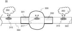
- FIG. 1is a diagram of an embodiment 10 showing use of an endoscopic instrument and shaft deployed in an alimentary canal.
- endoscopic instrument 100may be advanced through a patient's alimentary canal while a patient is, for example, under sedation.
- Endoscopic instrument 100may be advanced into a patient's mouth, into the patient's esophagus, through the cardia, stomach, and pyloric valve, for example, and into a patient's duodenum.
- embodiment 10represents merely a single implementation of a multi-lumen shaft used in association with an endoscopic instrument, and claimed subject matter is not limited to any particular embodiment, such as that of FIG. 1 .
- a multi-lumen shaftmay be used in association with endoscopic instruments and advanced into other body cavities, including body cavities of a human patient, animal patient, or into an intricate mechanical structure, or combinations thereof, for example.
- implementationsmay involve the use of other medical instruments that may be used to view internal structures of living organisms and/or mechanical apparatuses, and claimed subject matter is not limited in this respect.
- Endoscopic instrument 100may include camera 103 which, for example, may provide visual feedback to assist an endoscopic surgeon in positioning an endoscopic instrument.
- endoscopic instrument 100may additionally comprise a lamp or other illumination source so as to enable lighting of body cavities, such as alimentary canal 135 .
- endoscopic instrument 100may include a working channel that may permit tools, utensils, and other implements to be conveyed into, for example, a patient's alimentary canal and/or other body orifice.
- endoscopic instrument 100may be used to position multi-lumen shaft 140 to a location proximate with, for example, ostium 120 .
- ostium 120represents an opening, such as the hepatopancreatic ampulla, through which guide wire 150 may be advanced.
- endoscopic device 100is positioned proximate with ostium 120 , a surgeon may advance guide wire 150 through ostium 120 . Subsequent to penetration of ostium 120 , multi-lumen shaft 140 may also be advanced through ostium 120 . In an embodiment, advancement of guide wire 150 and/or multi-lumen shaft 140 may be enabled, at least in part, using camera 103 to obtain visual feedback of structures within, for example, alimentary canal 135 .
- multi-lumen shaft 140may be at least partially advanced toward stone 125 and further (i.e., distally) into biliary duct 105 .
- one or more of distal multi-lumen shaft port 110 and proximal multi-lumen shaft 115may be used to dispense fluoroscopic contrast dye, which may be used in conjunction with a fluoroscopic device, such as an x-ray machine, computer aided tomography scanner, or the like, to provide imagery to an endoscopic surgeon.
- an endoscopic surgeonmay locate ostium 120 by way of camera 103 , and for example, upon observing the entry of guide wire 150 and at least a distal portion of multi-lumen shaft 140 into ostium 120 , dispense a fluoroscopic contrast dye through, for example, distal multi-lumen shaft port 110 .
- Fluoroscopic contrast dyewhich may distribute within biliary duct 105 , may enable a surgeon to position multi-lumen shaft 140 relative to stone 125 . It should be noted, however, that some embodiments may involve positioning of a multi-lumen shaft without assistance from contrast dye, and claimed subject matter is not limited in this regard.
- multi-lumen shaft 140may introduce saline solution into expandable vessel 130 .
- Multi-lumen shaft 140may be configured to be nonreactive with saline or other solution introduced into expandable vessel 130 .
- expandable vessel 130may expand in size until, for example, vessel 130 comes into contact with an inner circumference of biliary duct 105 . Consequently, at least in some embodiments, expandable vessel 130 may form a temporary seal that may preclude contrast dye emanating from distal multi-lumen shaft port 110 to seep or leak towards ostium 120 .
- contrast fluidmay be permitted to fill biliary duct 105 .
- Filling of biliary 105 with contrast dyemay, for example, enable an endoscopic surgeon, radiologist, or other healthcare professional to observe more distal structures that may lie within and/or be in fluid communication with biliary duct 105 using, for example, a radioimaging device (e.g., an x-ray machine).
- a radioimaging devicee.g., an x-ray machine.
- additional structuressuch as the common bile duct, pancreatic duct, cystic duct, common hepatic duct, as well as other structures may be visible if expandable vessel is permitted to form a temporary seal of at least a portion of biliary duct 105 .
- liquids, such as contrast dye, emanating from distal multi-lumen shaft 110may provide other benefits, and claimed subject matter is not limited in this respect.
- multi-lumen shaft 140may additionally comprise proximal multi-lumen shaft port 115 .
- proximal multi-lumen shaft port 115may additionally be employed to dispense contrast dye within biliary duct 105 , for example. Consequently, if permitted to at least partially surround stone 125 , contrast dye may enable an endoscopic surgeon, radiologist, and/or other professional to monitor movement of stone 125 , as expandable vessel 130 is drawn toward ostium 120 . In some instances, it may be possible, for example, to observe the passing of stone 125 through ostium 120 , and into alimentary canal 135 .
- contrast dye dispensed by way of distal multi-lumen shaft port 110 and/or proximal multi-lumen shaft port 115represents one or more particular embodiments, and claimed subject matter is not limited in this respect.
- expandable vessel 130may be decreased in size, for example, by way of drawing saline solution from the expandable vessel and through multi-lumen shaft 140 .
- Multi-lumen shaft 140may then be retracted and stowed at a location internal to endoscopic device 100 . Stowage of multi-lumen shaft 140 within endoscopic device 100 may permit an endoscopic surgeon, for example, to remove multi-lumen shaft 140 and expandable vessel 130 from a patient.
- FIG. 2 Ais a diagram of an embodiment of a multi-lumen shaft employed as a removal device 15 .
- Removal device 15may comprise, for example, polycarbonate manifold 260 , polyolefin strain relief sheath 265 , polyurethane multi-lumen shaft 270 , and polyurethane expandable vessel 275 .
- polyolefin strain relief sheath 265may surround a portion of polyurethane multi-lumen shaft 270 in a manner that prevents or at least reduces likelihood of improperly bending or kinking polyurethane shaft 270 as shaft 270 and expandable vessel 275 are passed through a working channel of an endoscopic device, such as endoscopic device 100 .
- polyurethane shaft 270comprises a material that is nonreactive with radioimaging contrast dyes, saline solution, and/or other compressible or incompressible fluids that may be transported through polycarbonate manifold 260 and polyurethane shaft 270 for dispensing at a distal end portion of shaft 270 , such as a location nearby expandable vessel 275 , for example.
- Polycarbonate manifold 260may comprise one or more fluid coupling ports, such as fluid coupling ports 261 , 262 , and 263 , for example.
- fluid coupling port 261may be used to inject radioimaging contrast dye to a distal portion of polyurethane shaft 270 , such as, for example, distal output port 271 .
- fluid coupling port 262may be used to inject saline solution or other fluid, under suitable pressure, to inflate expandable vessel 275 by way of, for example, medial output port 272 (which may be obscured from view by expandable vessel 275 ).
- fluid coupling port 263may be used to inject radioimaging contrast dye to a proximal output port, such as, for example, proximal output port 273 .
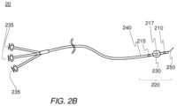
- FIG. 2 Bis a diagram of an embodiment of a multi-lumen shaft used with the removal device.
- the removal device of FIG. 2may be suitable, for example, for insertion into a working channel of an endoscopic instrument, such as endoscopic instrument 100 of FIG. 1 .
- embodiment 20may be suitable for insertion into other devices and/or instruments, and claimed subject matter is not limited in this respect.
- insertion of a multi-lumen shaft into a working channel of an endoscopic instrumentbegins, for example, with insertion of distal end portion 220 .
- multi-lumen shaft 240may be deployed, perhaps with the assistance of a camera, such as camera 103 shown in FIG. 1 , to a location proximate with an ostium or other opening into a body cavity. Beginning with guide wire 250 , multi-lumen shaft 240 may be inserted into an ostium.
- medial multi-lumen shaft port 217may dispense fluid, such as saline solution, which may increase volume of expandable vessel 230 .
- fluidsuch as saline solution
- Control for dispensing of saline solutionmay, for example, be provided by one or more of injector controls 235 .
- an expandable vesselmay expand to form a temporary seal within a biliary duct or other structure.
- contrast dyemay be dispensed from one or more of distal multi-lumen shaft port 210 and proximal multi-lumen shaft port 215 .
- Dispensing of contrast dye from distal manifold port 210may, for example, enable an endoscopic surgeon, radiologist, or other healthcare professional to observe imagery corresponding to additional structures located distally from multi-lumen shaft 240 , for example.
- Dispensing of contrast dyemay also permit real-time observation, by way of a fluoroscope (i.e., x-ray machine) of withdrawal of multi-lumen shaft 240 as well as urging of a stone or other object toward a patient's alimentary canal using expandable vessel 230 , for example.
- a fluoroscopei.e., x-ray machine
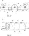
- FIG. 3is a diagram showing an embodiment of a multi-lumen shaft deploying an expandable vessel.
- multi-lumen shaft 340may be advanced by guiding the multi-lumen shaft to follow a guide wire (not shown in FIG. 3 ) coupled to sealed end portion 322 .
- Multi-lumen shaft 340may be inserted into a working channel of an endoscopic instrument, such as endoscopic instrument 100 of FIG. 1 , and inserted into a patient's alimentary canal, for example.
- contrast dye 350may be dispensed from one or more of distal multi-lumen shaft port 310 and proximal multi-lumen shaft port 315 .
- Contrast dyemay, at least in some embodiments, be employed to enable an endoscopic surgeon operating a fluoroscope to appropriately position multi-lumen shaft 340 proximate with a stone or other object for which removal may be desired.
- multi-lumen shaft 340 of FIG. 3may be useful in a variety of other scenarios, such as removal of objects lodged at other locations of a patient, and may make possible object removal from other living organisms and/or mechanical structures. Claimed subject matter is intended to embrace all such uses of multi-lumen shaft 340 .
- multi-lumen shaft 340may dispense saline solution into expandable vessel 330 way of multi-lumen shaft port 317 . If dispensed under a suitable pressure, for example, expandable vessel 330 may gain in volume until expandable vessel 330 occupies at least a considerable cross-section of a body orifice such as biliary duct 105 of FIG. 1 . Expandable vessel 330 may be fused by way of thermoplastic welding to multi-lumen shaft 340 at, for example, weld zones 331 and 332 .
- thermoplastic polyurethane expandable vessels fused to polyurethane multi-lumen shaftsmay lessen a need for adhesive used for affixing expandable vessels of other compositions to multi-lumen shafts, such as shaft 340 .
- use of thermoplastic polyurethane expandable vessels fused to polyurethane multi-lumen shaftsmay result, at least in part, in a much stronger bond than would result if latex expandable vessels were to be affixed, via an adhesive, to a polyurethane shaft.
- FIG. 4is a diagram showing a cross-section of an embodiment of a multi-lumen shaft.
- multi-lumen shaft 440may comprise first lumen 410 , which may be used to transport fluid, such as saline solution, for dispensing at fluid output port 415 .
- weld zone 431 and 432 of multi-lumen shaft 440may be seen to the left and right of fluid output port 415 .
- weld zones 431 and 432correspond to locations along a circumference of multi-lumen shaft 440 at which an expandable vessel, such as expandable vessel 330 of FIG. 3 , may be welded and/or fused to multi-lumen shaft 440 .
- Fusing of an inflatable vesselmay permit an expandable vessel to be filled with fluid, such as saline solution, so as to form a temporary seal within an orifice, such as biliary duct 105 of FIG. 1 , for example.
- fluidsuch as saline solution
- Multi-lumen shaft 440may also include contrast dye port 425 , located at a proximal end portion of multi-lumen shaft 440 .
- contrast dye port 425may be coupled to a second lumen 420 in a manner that permits contrast dye from second lumen 420 to be dispensed through contrast dye port 425 , located at a proximal end portion of the multi-lumen shaft.
- contrast dye port 435may be coupled to third lumen 430 in a manner that permits contrast dye from third lumen 430 to be dispensed via contrast dye port 435 .
- Multi-lumen shaft 440may also comprise guide wire lumen 460 in a manner that permits multi-lumen shaft 440 to slide along guide wire 450 .
- polycarbonate manifold 260may comprise a polycarbonate structure suitable for use with, for example, medical equipment.
- Polycarbonate materials suitable for construction of a manifoldmay be purchased from suppliers such as Westlake Plastics Company, PO Box 127, Lenni, Pa. 19052 (www.Westlakeplastics.com).
- alternative materials other than polycarbonate structuresmay comprise polycarbonate manifold 260 .
- Considerations for selection of a materialmay include, for example, materials comprising a suitable flexural modulus, flexural strength, hardness (Rockwell) impact strength, tensile elongation, tensile strength, coefficient of thermal expansion, heat deflection temperature, and specific gravity.
- Expandable vesselssuch as described herein may comprise a thermoplastic polyurethane elastomer that may be partially or fully thermoplastic.
- an expandable vesselmay comprise a linear segment block copolymer comprising “hard” and “soft” segments.
- a hard segmentmay comprise an aromatic or aliphatic material.
- Aromatic thermoplastic polyurethanesmay be based on isocyanates such as methylene diphenyl diisocyanate and/or related compounds.
- Aliphatic thermoplastic polyurethanesmay be based on isocyanates such as methylene dicyclohexyl diisocyanate (H12MDI). Isocyanates may be combined with short-chain diols to form a “hard” segment. It should be noted that these are merely examples of engineered thermoplastic polyurethanes that may be used to form an expandable vessel, however claimed subject matter is not limited in this regard.
- FIG. 5is a flow diagram of a process for using an embodiment of a multi-lumen shaft in association with an endoscopic procedure.
- the arrangement of components in FIG. 1may be suitable for performing the method of embodiment 50 .
- claimed subject matteris not limited to the particular implementation of any particular figure shown and described herein and alternate arrangements of components in other implementations may be used.
- Example embodiments, such as embodiment 50 shown in FIG. 5may include blocks in addition to those shown and described, fewer blocks, blocks occurring in an order different than may be identified, or any combination thereof.
- a multi-lumen shaftmay be inserted into a location distal to an object for removal. 510 may be preceded by inserting a guide wire into an orifice, such as a bile duct, and dispensing fluoroscopic contrast dye in a manner that permits an endoscopic surgeon, for example, to observe a position of an object to be removed.
- an orificesuch as a bile duct
- fluoroscopic contrast dyein a manner that permits an endoscopic surgeon, for example, to observe a position of an object to be removed.
- expandable vesselmay be inflated until the expandable vessel forms a temporary seal which may, for example.
- contrast dyemay be dispensed so as to permit radioimaging of additional structures, such as biliary tree, which may be coupled to a patient's bile duct.
- 530may be employed to enable radioimaging of other structures, and claimed subject matter is not limited in this respect.
- a multi-lumen shaftwhich may be fused to an expandable vessel, be drawn toward an ostium or other opening in a manner that permits a stone or other object to empty into a patient's alimentary canal.
- embodimentsmay permit the removal of other objects, which may be lodged at locations other than ducts coupled to the elementary canal, and claimed subject matter is not limited in this regard.
Landscapes
- Health & Medical Sciences (AREA)
- Life Sciences & Earth Sciences (AREA)
- General Health & Medical Sciences (AREA)
- Heart & Thoracic Surgery (AREA)
- Veterinary Medicine (AREA)
- Public Health (AREA)
- Engineering & Computer Science (AREA)
- Anesthesiology (AREA)
- Biomedical Technology (AREA)
- Animal Behavior & Ethology (AREA)
- Hematology (AREA)
- Geometry (AREA)
- Physics & Mathematics (AREA)
- Pulmonology (AREA)
- Biophysics (AREA)
- Endoscopes (AREA)
- Vascular Medicine (AREA)
Abstract
Description
Claims (6)
Priority Applications (2)
| Application Number | Priority Date | Filing Date | Title |
|---|---|---|---|
| US13/843,982US11684747B2 (en) | 2013-03-15 | 2013-03-15 | Multi-lumen shaft used with endoscopic device |
| US18/342,274US12226589B2 (en) | 2013-03-15 | 2023-06-27 | Multi-lumen shaft used with endoscopic device |
Applications Claiming Priority (1)
| Application Number | Priority Date | Filing Date | Title |
|---|---|---|---|
| US13/843,982US11684747B2 (en) | 2013-03-15 | 2013-03-15 | Multi-lumen shaft used with endoscopic device |
Related Child Applications (1)
| Application Number | Title | Priority Date | Filing Date |
|---|---|---|---|
| US18/342,274DivisionUS12226589B2 (en) | 2013-03-15 | 2023-06-27 | Multi-lumen shaft used with endoscopic device |
Publications (2)
| Publication Number | Publication Date |
|---|---|
| US20140277064A1 US20140277064A1 (en) | 2014-09-18 |
| US11684747B2true US11684747B2 (en) | 2023-06-27 |
Family
ID=51531076
Family Applications (2)
| Application Number | Title | Priority Date | Filing Date |
|---|---|---|---|
| US13/843,982Active2035-09-18US11684747B2 (en) | 2013-03-15 | 2013-03-15 | Multi-lumen shaft used with endoscopic device |
| US18/342,274ActiveUS12226589B2 (en) | 2013-03-15 | 2023-06-27 | Multi-lumen shaft used with endoscopic device |
Family Applications After (1)
| Application Number | Title | Priority Date | Filing Date |
|---|---|---|---|
| US18/342,274ActiveUS12226589B2 (en) | 2013-03-15 | 2023-06-27 | Multi-lumen shaft used with endoscopic device |
Country Status (1)
| Country | Link |
|---|---|
| US (2) | US11684747B2 (en) |
Families Citing this family (1)
| Publication number | Priority date | Publication date | Assignee | Title |
|---|---|---|---|---|
| US9326783B2 (en)* | 2013-03-15 | 2016-05-03 | Rsh, Llc | Removal tool for use with endoscopic device |
Citations (38)
| Publication number | Priority date | Publication date | Assignee | Title |
|---|---|---|---|---|
| US4003382A (en) | 1975-07-25 | 1977-01-18 | Ethicon, Inc. | Retention catheter and method of manufacture |
| US4295464A (en) | 1980-03-21 | 1981-10-20 | Shihata Alfred A | Ureteric stone extractor with two ballooned catheters |
| US4469100A (en) | 1983-03-14 | 1984-09-04 | Hardwick Charles W | Intussuscepting balloon catheter for stone extraction |
| US4930496A (en) | 1988-07-22 | 1990-06-05 | Vance Products, Inc. | Method and device for removing a stone from a ureter using extracorporeal shock wave lithotripsy |
| US5059178A (en) | 1988-08-03 | 1991-10-22 | Ya Wang D | Method of percutaneously removing a thrombus from a blood vessel by using catheters and system for removing a thrombus from a blood vessel by using catheters |
| US5195955A (en) | 1989-11-14 | 1993-03-23 | Don Michael T Anthony | Device for removal of embolic debris |
| US5334143A (en) | 1992-04-17 | 1994-08-02 | Carroll Brendon J | Method to remove common bile duct stones |
| US5417653A (en)* | 1993-01-21 | 1995-05-23 | Sahota; Harvinder | Method for minimizing restenosis |
| US5662609A (en)* | 1990-02-26 | 1997-09-02 | Endoluminal Therapeutics, Inc. | Method and apparatus for treatment of focal disease in hollow tubular organs and other tissue lumens |
| US5840066A (en)* | 1995-10-26 | 1998-11-24 | Tokai Kobunshi Kagaku Kabushikigaisha | Infusion catheter |
| US5921957A (en)* | 1994-07-12 | 1999-07-13 | Scimed Life Systems, Inc. | Intravascular dilation catheter |
| US6056721A (en) | 1997-08-08 | 2000-05-02 | Sunscope International, Inc. | Balloon catheter and method |
| US20010001113A1 (en) | 1998-04-21 | 2001-05-10 | Florencia Lim | Balloon catheter |
| WO2002034313A2 (en) | 2000-10-24 | 2002-05-02 | Polyzen Inc. | Isotropically expansible balloon articles useful in in vivo lumenal procedures, and methods of making such balloon articles |
| US6390967B1 (en)* | 2000-09-14 | 2002-05-21 | Xoft Microtube, Inc. | Radiation for inhibiting hyperplasia after intravascular intervention |
| US20030036728A1 (en) | 1998-08-06 | 2003-02-20 | Samson Wilfred J. | Aortic catheter with porous aortic arch balloon |
| US20030236496A1 (en)* | 1999-08-03 | 2003-12-25 | Samson Wilfred J. | Aortic catheter with porous aortic arch balloon and methods for selective aortic perfusion |
| US6692484B1 (en) | 1999-07-17 | 2004-02-17 | Wilson-Cook Medical Incorporated | Devices for extracting biliary or urinary stones |
| US20040267195A1 (en) | 2003-06-24 | 2004-12-30 | Arnoldo Currlin | Catheter balloon having visible marker |
| EP1502609A1 (en) | 2003-07-29 | 2005-02-02 | Terumo Kabushiki Kaisha | Catheter with expandable member |
| US20050065544A1 (en)* | 2001-12-07 | 2005-03-24 | Youichi Yamaguchi | Balloon catheter and method of manufacturing balloon catheter |
| US20050228417A1 (en) | 2004-03-26 | 2005-10-13 | Teitelbaum George P | Devices and methods for removing a matter from a body cavity of a patient |
| US20050272975A1 (en)* | 2004-03-23 | 2005-12-08 | Mcweeney John O | In-vivo visualization system |
| US20070270897A1 (en) | 2006-05-16 | 2007-11-22 | Wilson-Cook Medical Inc. | Balloon cuff |
| US20080188866A1 (en) | 2007-02-05 | 2008-08-07 | Wilson-Cook Medical Inc. | Apparatus and methods for removing relatively large and small stones from a body passage |
| US20080228138A1 (en) | 2005-03-31 | 2008-09-18 | Van Sloten Leonard A | Catheter with balloon having visual marker |
| US20080243068A1 (en) | 2005-12-29 | 2008-10-02 | Kamal Ramzipoor | Methods and apparatus for treatment of venous insufficiency |
| US20080319376A1 (en)* | 2007-06-22 | 2008-12-25 | Ekos Corporation | Method and apparatus for treatment of intracranial hemorrhages |
| US20090171369A1 (en) | 2007-12-27 | 2009-07-02 | Wilson-Cook Medical Inc. | Two-part extraction balloon |
| US20090187144A1 (en) | 2008-01-18 | 2009-07-23 | Swaminathan Jayaraman | Delivery of therapeutic and marking substance through intra lumen expansion of a delivery device |
| US20090187098A1 (en) | 2004-04-21 | 2009-07-23 | Acclarent, Inc. | Devices, Systems and Methods for Diagnosing and Treating Sinusitis and Other Disorders of the Ears, Nose, and/or Throat |
| US20090306769A1 (en) | 2008-06-06 | 2009-12-10 | Boston Scientific Scimed, Inc. | Medical balloon made with hybrid polymer-ceramic material and method of making and using the same |
| US8029494B2 (en) | 2005-10-24 | 2011-10-04 | Cook Medical Technologies Llc | Method of removing biliary stones with coaxial catheter device |
| WO2012156914A2 (en) | 2011-05-15 | 2012-11-22 | By-Pass, Inc. | Microporous balloon catheter, delivery system, and methods of manufacture and use |
| US20130237950A1 (en) | 2010-09-17 | 2013-09-12 | Abbott Cardiovascular Systems Inc. | Length and diameter adjustable balloon catheter |
| US20140276585A1 (en) | 2013-03-15 | 2014-09-18 | Abbott Cardiovascular Systems Inc. | Length adjustable balloon catheter for multiple indications |
| US20140276530A1 (en) | 2013-03-12 | 2014-09-18 | Abbott Cardiovascular Systems Inc. | Length and diameter adjustable balloon catheter for drug delivery |
| US20140277063A1 (en) | 2013-03-15 | 2014-09-18 | Rsh, Llc | Removal tool for use with endoscopic device |
Family Cites Families (2)
| Publication number | Priority date | Publication date | Assignee | Title |
|---|---|---|---|---|
| US6485500B1 (en)* | 2000-03-21 | 2002-11-26 | Advanced Cardiovascular Systems, Inc. | Emboli protection system |
| US20030120256A1 (en)* | 2001-07-03 | 2003-06-26 | Syntheon, Llc | Methods and apparatus for sclerosing the wall of a varicose vein |
- 2013
- 2013-03-15USUS13/843,982patent/US11684747B2/enactiveActive
- 2023
- 2023-06-27USUS18/342,274patent/US12226589B2/enactiveActive
Patent Citations (43)
| Publication number | Priority date | Publication date | Assignee | Title |
|---|---|---|---|---|
| US4003382A (en) | 1975-07-25 | 1977-01-18 | Ethicon, Inc. | Retention catheter and method of manufacture |
| US4295464A (en) | 1980-03-21 | 1981-10-20 | Shihata Alfred A | Ureteric stone extractor with two ballooned catheters |
| US4469100A (en) | 1983-03-14 | 1984-09-04 | Hardwick Charles W | Intussuscepting balloon catheter for stone extraction |
| US4930496A (en) | 1988-07-22 | 1990-06-05 | Vance Products, Inc. | Method and device for removing a stone from a ureter using extracorporeal shock wave lithotripsy |
| US5059178A (en) | 1988-08-03 | 1991-10-22 | Ya Wang D | Method of percutaneously removing a thrombus from a blood vessel by using catheters and system for removing a thrombus from a blood vessel by using catheters |
| US5195955A (en) | 1989-11-14 | 1993-03-23 | Don Michael T Anthony | Device for removal of embolic debris |
| US5662609A (en)* | 1990-02-26 | 1997-09-02 | Endoluminal Therapeutics, Inc. | Method and apparatus for treatment of focal disease in hollow tubular organs and other tissue lumens |
| US5334143A (en) | 1992-04-17 | 1994-08-02 | Carroll Brendon J | Method to remove common bile duct stones |
| US5417653A (en)* | 1993-01-21 | 1995-05-23 | Sahota; Harvinder | Method for minimizing restenosis |
| US5921957A (en)* | 1994-07-12 | 1999-07-13 | Scimed Life Systems, Inc. | Intravascular dilation catheter |
| US5840066A (en)* | 1995-10-26 | 1998-11-24 | Tokai Kobunshi Kagaku Kabushikigaisha | Infusion catheter |
| US6056721A (en) | 1997-08-08 | 2000-05-02 | Sunscope International, Inc. | Balloon catheter and method |
| US20010001113A1 (en) | 1998-04-21 | 2001-05-10 | Florencia Lim | Balloon catheter |
| US7892469B2 (en)* | 1998-04-21 | 2011-02-22 | Advanced Cardiovascular Systems, Inc. | Method of making a non-compliant balloon for a catheter |
| US20030036728A1 (en) | 1998-08-06 | 2003-02-20 | Samson Wilfred J. | Aortic catheter with porous aortic arch balloon |
| US6547760B1 (en) | 1998-08-06 | 2003-04-15 | Cardeon Corporation | Aortic catheter with porous aortic arch balloon and methods for selective aortic perfusion |
| US6695811B2 (en) | 1998-08-06 | 2004-02-24 | Cardeon Corporation | Aortic catheter with porous aortic arch balloon |
| US6692484B1 (en) | 1999-07-17 | 2004-02-17 | Wilson-Cook Medical Incorporated | Devices for extracting biliary or urinary stones |
| US20030236496A1 (en)* | 1999-08-03 | 2003-12-25 | Samson Wilfred J. | Aortic catheter with porous aortic arch balloon and methods for selective aortic perfusion |
| US6390967B1 (en)* | 2000-09-14 | 2002-05-21 | Xoft Microtube, Inc. | Radiation for inhibiting hyperplasia after intravascular intervention |
| WO2002034313A2 (en) | 2000-10-24 | 2002-05-02 | Polyzen Inc. | Isotropically expansible balloon articles useful in in vivo lumenal procedures, and methods of making such balloon articles |
| US20050065544A1 (en)* | 2001-12-07 | 2005-03-24 | Youichi Yamaguchi | Balloon catheter and method of manufacturing balloon catheter |
| US20040267195A1 (en) | 2003-06-24 | 2004-12-30 | Arnoldo Currlin | Catheter balloon having visible marker |
| EP1502609A1 (en) | 2003-07-29 | 2005-02-02 | Terumo Kabushiki Kaisha | Catheter with expandable member |
| US20050272975A1 (en)* | 2004-03-23 | 2005-12-08 | Mcweeney John O | In-vivo visualization system |
| US20050228417A1 (en) | 2004-03-26 | 2005-10-13 | Teitelbaum George P | Devices and methods for removing a matter from a body cavity of a patient |
| US20090187098A1 (en) | 2004-04-21 | 2009-07-23 | Acclarent, Inc. | Devices, Systems and Methods for Diagnosing and Treating Sinusitis and Other Disorders of the Ears, Nose, and/or Throat |
| US20080228138A1 (en) | 2005-03-31 | 2008-09-18 | Van Sloten Leonard A | Catheter with balloon having visual marker |
| US8029494B2 (en) | 2005-10-24 | 2011-10-04 | Cook Medical Technologies Llc | Method of removing biliary stones with coaxial catheter device |
| US20080243068A1 (en) | 2005-12-29 | 2008-10-02 | Kamal Ramzipoor | Methods and apparatus for treatment of venous insufficiency |
| US20070270897A1 (en) | 2006-05-16 | 2007-11-22 | Wilson-Cook Medical Inc. | Balloon cuff |
| US20080188866A1 (en) | 2007-02-05 | 2008-08-07 | Wilson-Cook Medical Inc. | Apparatus and methods for removing relatively large and small stones from a body passage |
| US20080319376A1 (en)* | 2007-06-22 | 2008-12-25 | Ekos Corporation | Method and apparatus for treatment of intracranial hemorrhages |
| US20090171369A1 (en) | 2007-12-27 | 2009-07-02 | Wilson-Cook Medical Inc. | Two-part extraction balloon |
| US20090187144A1 (en) | 2008-01-18 | 2009-07-23 | Swaminathan Jayaraman | Delivery of therapeutic and marking substance through intra lumen expansion of a delivery device |
| US20090306769A1 (en) | 2008-06-06 | 2009-12-10 | Boston Scientific Scimed, Inc. | Medical balloon made with hybrid polymer-ceramic material and method of making and using the same |
| US20130237950A1 (en) | 2010-09-17 | 2013-09-12 | Abbott Cardiovascular Systems Inc. | Length and diameter adjustable balloon catheter |
| WO2012156914A2 (en) | 2011-05-15 | 2012-11-22 | By-Pass, Inc. | Microporous balloon catheter, delivery system, and methods of manufacture and use |
| US20140276530A1 (en) | 2013-03-12 | 2014-09-18 | Abbott Cardiovascular Systems Inc. | Length and diameter adjustable balloon catheter for drug delivery |
| US20140276585A1 (en) | 2013-03-15 | 2014-09-18 | Abbott Cardiovascular Systems Inc. | Length adjustable balloon catheter for multiple indications |
| US20140277063A1 (en) | 2013-03-15 | 2014-09-18 | Rsh, Llc | Removal tool for use with endoscopic device |
| US9326783B2 (en) | 2013-03-15 | 2016-05-03 | Rsh, Llc | Removal tool for use with endoscopic device |
| US20160278799A1 (en) | 2013-03-15 | 2016-09-29 | Rsh, Llc | Removal tool for use with endoscopic device |
Non-Patent Citations (24)
| Title |
|---|
| PCT/US14/29515 / WO2014144915: International Search Report, dated Jul. 3, 2014, 6 pages. |
| PCT/US14/29515 / WO2014144915: IPRP, Jul. 14, 2015, 27 pages. |
| PCT/US14/29515 / WO2014144915: Publication and ISR, Sep. 18, 2014, 34 pages. |
| PCT/US14/29515 / WO2014144915: Written Opinion of the International Search Authority, dated Sep. 15, 2015, 10 pages. |
| U.S. Appl. No. 13/843,891, filed Mar. 15, 2013, 36 pages. |
| U.S. Appl. No. 13/843,891: After Final Consideration Program Request, dated Feb. 10, 2016, 13 pages. |
| U.S. Appl. No. 13/843,891: Amendment after Notice of Allowance, dated Mar. 9, 2016, 3 pages. |
| U.S. Appl. No. 13/843,891: Amendment/Req. Reconsideration—After Non-Final Rejection, dated Aug. 21, 2015, 13 pages. |
| U.S. Appl. No. 13/843,891: Applicant initiated interview summary, dated Feb. 5, 2016, 3 pages. |
| U.S. Appl. No. 13/843,891: Corrected Application Data Sheet, Mar. 1, 2016, 7 pages. |
| U.S. Appl. No. 13/843,891: Filing Receipt, Mar. 9, 2016, 4 pages. |
| U.S. Appl. No. 13/843,891: Filing Receipt, May 22, 2013, 3 pages. |
| U.S. Appl. No. 13/843,891: Filing Receipt, May 29, 2013, 3 pages. |
| U.S. Appl. No. 13/843,891: Final Rejection, dated Dec. 4, 2015, 13 pages. |
| U.S. Appl. No. 13/843,891: Final Rejection, dated Sep. 29, 2015, 13 pages. |
| U.S. Appl. No. 13/843,891: Issue Fee Payment, Mar. 31, 2016, 1 page. |
| U.S. Appl. No. 13/843,891: Issue Notification, dated Apr. 13, 2016, 1 page. |
| U.S. Appl. No. 13/843,891: Non-Final Rejection, dated May 21, 2015, 11 pages. |
| U.S. Appl. No. 13/843,891: Notice of Allowance and Fees, dated Feb. 23, 2016, 19 pages. |
| U.S. Appl. No. 13/843,891: Notice of Publication, dated Sep. 18, 2014, 1 page. |
| U.S. Appl. No. 13/843,891: Response After Final Action, dated Nov. 30, 2015, 9 pages. |
| U.S. Appl. No. 15/087,754, filed Mar. 31, 2016, 43 pages. |
| U.S. Appl. No. 15/087,754: Filing Receipt, Apr. 15, 2016, 3 pages. |
| U.S. Appl. No. 15/087,754: Notice to File Missing Parts, dated Apr. 15, 2016, 2 pages. |
Also Published As
| Publication number | Publication date |
|---|---|
| US12226589B2 (en) | 2025-02-18 |
| US20140277064A1 (en) | 2014-09-18 |
| US20230338699A1 (en) | 2023-10-26 |
Similar Documents
| Publication | Publication Date | Title |
|---|---|---|
| US8298134B2 (en) | Eccentric dilation balloons for use with endoscopes | |
| US7011675B2 (en) | Endoscopic stent delivery system and method | |
| US10463232B2 (en) | Anchored guidewire | |
| US20090287050A1 (en) | Eccentric Dilation Balloons for Use of Endoscopes | |
| JP7637190B2 (en) | Balloon-assisted endoluminal prosthesis deployment | |
| US20080183039A1 (en) | Balloon Positioning System for Endoscopic Access | |
| JP5785951B2 (en) | Low length one-way valve | |
| US20210205107A9 (en) | Sleeve tube and method of use | |
| US12226589B2 (en) | Multi-lumen shaft used with endoscopic device | |
| EP2692386A1 (en) | Device for otorhinolaryngological therapy | |
| US11540849B2 (en) | Removal tool for use with endoscopic device | |
| JP2007229499A (en) | Extension type balloon catheter | |
| US20180303663A1 (en) | Balloon catheter for endovascular temperature control | |
| US20170112651A1 (en) | Sleeve tube and method of use | |
| US8663159B2 (en) | Endoscopic device | |
| US20190358069A1 (en) | Sleeve tube and method of use | |
| Barthel | Eccentric dilation balloons for use with endoscopes |
Legal Events
| Date | Code | Title | Description |
|---|---|---|---|
| AS | Assignment | Owner name:RSH, LLC, TEXAS Free format text:ASSIGNMENT OF ASSIGNORS INTEREST;ASSIGNORS:DUSBABEK, ANDREW JOSEPH;OLSON, SCOTT ARVIN;SPRINGS, CHRISTEN ANDREW;AND OTHERS;REEL/FRAME:030656/0236 Effective date:20130401 | |
| AS | Assignment | Owner name:CONMED CORPORATION, NEW YORK Free format text:ASSIGNMENT OF ASSIGNORS INTEREST;ASSIGNOR:RSH, LLC;REEL/FRAME:043326/0815 Effective date:20170426 | |
| STPP | Information on status: patent application and granting procedure in general | Free format text:FINAL REJECTION MAILED | |
| STPP | Information on status: patent application and granting procedure in general | Free format text:DOCKETED NEW CASE - READY FOR EXAMINATION | |
| STPP | Information on status: patent application and granting procedure in general | Free format text:NON FINAL ACTION MAILED | |
| STPP | Information on status: patent application and granting procedure in general | Free format text:RESPONSE TO NON-FINAL OFFICE ACTION ENTERED AND FORWARDED TO EXAMINER | |
| STPP | Information on status: patent application and granting procedure in general | Free format text:FINAL REJECTION MAILED | |
| STPP | Information on status: patent application and granting procedure in general | Free format text:RESPONSE AFTER FINAL ACTION FORWARDED TO EXAMINER | |
| STPP | Information on status: patent application and granting procedure in general | Free format text:DOCKETED NEW CASE - READY FOR EXAMINATION | |
| STPP | Information on status: patent application and granting procedure in general | Free format text:FINAL REJECTION MAILED | |
| STPP | Information on status: patent application and granting procedure in general | Free format text:DOCKETED NEW CASE - READY FOR EXAMINATION | |
| STPP | Information on status: patent application and granting procedure in general | Free format text:NON FINAL ACTION MAILED | |
| STPP | Information on status: patent application and granting procedure in general | Free format text:RESPONSE TO NON-FINAL OFFICE ACTION ENTERED AND FORWARDED TO EXAMINER | |
| STPP | Information on status: patent application and granting procedure in general | Free format text:FINAL REJECTION MAILED | |
| STPP | Information on status: patent application and granting procedure in general | Free format text:RESPONSE AFTER FINAL ACTION FORWARDED TO EXAMINER | |
| STPP | Information on status: patent application and granting procedure in general | Free format text:ADVISORY ACTION MAILED | |
| STPP | Information on status: patent application and granting procedure in general | Free format text:DOCKETED NEW CASE - READY FOR EXAMINATION | |
| STPP | Information on status: patent application and granting procedure in general | Free format text:NON FINAL ACTION MAILED | |
| STPP | Information on status: patent application and granting procedure in general | Free format text:FINAL REJECTION MAILED | |
| STPP | Information on status: patent application and granting procedure in general | Free format text:ADVISORY ACTION MAILED | |
| STPP | Information on status: patent application and granting procedure in general | Free format text:NON FINAL ACTION MAILED | |
| STPP | Information on status: patent application and granting procedure in general | Free format text:FINAL REJECTION MAILED | |
| STCF | Information on status: patent grant | Free format text:PATENTED CASE | |
| AS | Assignment | Owner name:JPMORGAN CHASE BANK, N.A., AS ADMINISTRATIVE AGENT, ILLINOIS Free format text:SECURITY INTEREST;ASSIGNORS:CONMED CORPORATION;BIOREZ, INC.;BUFFALO FILTER LLC;AND OTHERS;REEL/FRAME:072097/0762 Effective date:20250610 |