US11684529B2 - Mattress cover sensor method - Google Patents
Mattress cover sensor methodDownload PDFInfo
- Publication number
- US11684529B2 US11684529B2US17/398,312US202117398312AUS11684529B2US 11684529 B2US11684529 B2US 11684529B2US 202117398312 AUS202117398312 AUS 202117398312AUS 11684529 B2US11684529 B2US 11684529B2
- Authority
- US
- United States
- Prior art keywords
- cover
- sensor unit
- providing
- sensor
- patient
- Prior art date
- Legal status (The legal status is an assumption and is not a legal conclusion. Google has not performed a legal analysis and makes no representation as to the accuracy of the status listed.)
- Active, expires
Links
- 230000014759maintenance of locationEffects0.000claimsdescription22
- 210000004197pelvisAnatomy0.000claimsdescription14
- 239000000463materialSubstances0.000claimsdescription7
- 206010021639IncontinenceDiseases0.000claimsdescription3
- 210000004243sweatAnatomy0.000claimsdescription3
- 208000004210Pressure UlcerDiseases0.000description9
- 230000009471actionEffects0.000description5
- 239000006260foamSubstances0.000description5
- 230000015572biosynthetic processEffects0.000description3
- 230000008859changeEffects0.000description3
- 238000004891communicationMethods0.000description3
- 238000003780insertionMethods0.000description3
- 230000037431insertionEffects0.000description3
- 239000004753textileSubstances0.000description3
- 238000004140cleaningMethods0.000description2
- 230000008878couplingEffects0.000description2
- 238000010168coupling processMethods0.000description2
- 238000005859coupling reactionMethods0.000description2
- 238000001514detection methodMethods0.000description2
- 239000000945fillerSubstances0.000description2
- 239000007788liquidSubstances0.000description2
- 230000004044responseEffects0.000description2
- 206010011985Decubitus ulcerDiseases0.000description1
- JOYRKODLDBILNP-UHFFFAOYSA-NEthyl urethaneChemical compoundCCOC(N)=OJOYRKODLDBILNP-UHFFFAOYSA-N0.000description1
- 239000004677NylonSubstances0.000description1
- 230000004888barrier functionEffects0.000description1
- 230000008901benefitEffects0.000description1
- 238000010586diagramMethods0.000description1
- 238000005516engineering processMethods0.000description1
- 230000007613environmental effectEffects0.000description1
- 229920005570flexible polymerPolymers0.000description1
- 230000010354integrationEffects0.000description1
- 230000004048modificationEffects0.000description1
- 238000012986modificationMethods0.000description1
- 229920001778nylonPolymers0.000description1
- 208000017520skin diseaseDiseases0.000description1
- 230000036559skin healthEffects0.000description1
- 239000000126substanceSubstances0.000description1
- 238000002560therapeutic procedureMethods0.000description1
- 238000005406washingMethods0.000description1
- XLYOFNOQVPJJNP-UHFFFAOYSA-NwaterSubstancesOXLYOFNOQVPJJNP-UHFFFAOYSA-N0.000description1
Images


Classifications
- A—HUMAN NECESSITIES
- A61—MEDICAL OR VETERINARY SCIENCE; HYGIENE
- A61G—TRANSPORT, PERSONAL CONVEYANCES, OR ACCOMMODATION SPECIALLY ADAPTED FOR PATIENTS OR DISABLED PERSONS; OPERATING TABLES OR CHAIRS; CHAIRS FOR DENTISTRY; FUNERAL DEVICES
- A61G7/00—Beds specially adapted for nursing; Devices for lifting patients or disabled persons
- A61G7/05—Parts, details or accessories of beds
- A61G7/057—Arrangements for preventing bed-sores or for supporting patients with burns, e.g. mattresses specially adapted therefor
- A61G7/05769—Arrangements for preventing bed-sores or for supporting patients with burns, e.g. mattresses specially adapted therefor with inflatable chambers
- A61G7/05776—Arrangements for preventing bed-sores or for supporting patients with burns, e.g. mattresses specially adapted therefor with inflatable chambers with at least two groups of alternately inflated chambers
- A—HUMAN NECESSITIES
- A61—MEDICAL OR VETERINARY SCIENCE; HYGIENE
- A61G—TRANSPORT, PERSONAL CONVEYANCES, OR ACCOMMODATION SPECIALLY ADAPTED FOR PATIENTS OR DISABLED PERSONS; OPERATING TABLES OR CHAIRS; CHAIRS FOR DENTISTRY; FUNERAL DEVICES
- A61G7/00—Beds specially adapted for nursing; Devices for lifting patients or disabled persons
- A61G7/05—Parts, details or accessories of beds
- A61G7/057—Arrangements for preventing bed-sores or for supporting patients with burns, e.g. mattresses specially adapted therefor
- A61G7/05769—Arrangements for preventing bed-sores or for supporting patients with burns, e.g. mattresses specially adapted therefor with inflatable chambers
- A—HUMAN NECESSITIES
- A61—MEDICAL OR VETERINARY SCIENCE; HYGIENE
- A61G—TRANSPORT, PERSONAL CONVEYANCES, OR ACCOMMODATION SPECIALLY ADAPTED FOR PATIENTS OR DISABLED PERSONS; OPERATING TABLES OR CHAIRS; CHAIRS FOR DENTISTRY; FUNERAL DEVICES
- A61G2203/00—General characteristics of devices
- A61G2203/30—General characteristics of devices characterised by sensor means
- A61G2203/46—General characteristics of devices characterised by sensor means for temperature
Definitions
- the present disclosureis related to patient supports, and in particular to patient supports with sensors. More specifically, the present disclosure is related to a patient support apparatus including at least one sensor for detecting conditions at the interface of the patient support apparatus and a patient positioned on the patient support apparatus.
- Bed soressometimes called pressure ulcers or decubitus ulcers, are a common type of skin breakdown experienced by patients. Conditions at the interface of a patient support apparatus and a patient's skin may be considered when determining a risk level for bed sore formation. Conditions evaluated at the interface of a patient support apparatus and a patient's skin that may be considered include moisture, temperature, skin health, and the like.
- Some care centersimplement manual routines for checking conditions at the interface of a patient support apparatus and a patient's skin in order to determine a risk level for bed sores. The determined risk levels can then be used to schedule therapies to mitigate the risk of bed sore formation. Such manual checks may not be performed with great frequency in some care centers on account of low staffing or high occupancy.
- a patient support apparatusmay include a cushion, a cover, and a sensor unit.
- the covermay overlie the cushion and may be configured to support a patient.
- the sensor unitmay be coupled to the cover.
- the covermay be formed to include a slit.
- the sensor unitmay include a sensor and a flexible mount coupled to the sensor.
- the flexible mountmay be inserted through the slit formed in the cover to couple the sensor unit to the cover.
- the flexible mountmay include a stem portion and a retention portion.
- the stem portionmay be inserted through the slit while the retention portion engages the cover along the slit to retain the sensor in place relative to the cover.
- the retention portionmay be U-shaped. In other embodiments, the retention portion is V-shaped or triangular.
- the flexible mountmay include a flexible film and a circuit.
- the circuitmay be coupled to the flexible film to provide an electrical path from the sensor.
- the covermay include a top layer, a middle layer, and a bottom layer.
- the slit formed in the covermay extend through the top layer of the cover.
- the middle layermay be made of a three-dimensional material configured to conduct air between the top layer and the bottom layer.
- the patient support apparatusmay also include an air box.
- the air boxmay be coupled to the cover and may be configured to provide air to the middle layer of the cover.
- the air boxmay include a blower and a controller.
- the blowermay be coupled to the middle layer of the cover.
- the controllermay be coupled to the blower and to the sensor unit. The controller may be configured to adjust operation of the blower based on information from the sensor unit.
- the cushionincludes a plurality of inflatable bladders. It is contemplated that the patient support apparatus may also include a lower ticking coupled to the cover to encase the plurality of inflatable bladders.
- the patient support apparatusmay also include an air box.
- the air boxmay include a blower and a controller.
- the blowermay be coupled to the plurality of inflatable bladders.
- the controllermay be coupled to the sensor unit and the blower.
- the controllermay be configured to adjust the operation of the blower based on information from the sensor unit.
- the sensor unitmay be located in a central portion of the cover.
- the central portion of the covermay be situated between a head end and a foot end of the cover so that the sensor unit is arranged to underlie the pelvic region of a patient.
- a patient support apparatusmay include a cushion, a cover and a wireless sensor unit.
- the covermay overlie a top side of the cushion and may be configured to support a patient.
- the wireless sensor unitmay be configured to detect moisture and may be coupled to the cover between a head end and a foot end of the cover.
- the wireless sensor unitmay be located in a central region of the cover to underlie a patient's pelvic area when a patient is lying on the cover.
- the covermay be a topper overlying the top side of the cushion.
- the toppermay be configured to conduct air along the top side of the surface.
- the patient support apparatusmay also include an air box including a blower and a controller.
- the blowermay be coupled to the topper.
- the controllermay be coupled to the blower and may be in wireless communication with the wireless sensor unit.
- the controllermay be configured to adjust the operation of the blower to change the amount of air provided to the topper based on information received from the sensor unit.
- the cushionmay include a plurality of inflatable bladders.
- the patient support apparatusmay include an air box including a blower and a controller.
- the blowermay be coupled to the plurality of inflatable bladders.
- the controllermay be coupled to the blower and may be in wireless communication with the wireless sensor unit.
- the controllermay be configured to operate the blower to adjust the pressure in the plurality of inflatable bladders based on information received from the wireless sensor unit.
- the wireless sensor unitmay be passive.
- the patient support apparatusmay include a reader spaced apart from the wireless sensor unit.
- the readermay be configured to power the sensor unit and to receive data from the wireless sensor unit.
- the readermay be arranged to underlie the wireless sensor unit.
- the patient support apparatusmay include a frame including deck and a base.
- the deckmay underlie the cushion and the cover.
- the basemay underlie the deck to support the deck above a floor.
- the readermay be coupled to the deck.
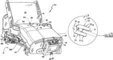
- FIG. 1is a perspective view of a patient support apparatus including a support frame, a support surface with a sensor unit, and an air box pneumatically coupled to the support surface;
- FIG. 2is a cut-away perspective view of the support surface and the air box of FIG. 1 showing that the sensor unit is coupled to a topper included in the support surface located beneath a coverlet included in the support surface;
- FIG. 3is a detail view of the moisture sensor of FIG. 2 with the moisture sensor unit inserted into a slit formed in the topper of the support surface to removably couple the sensor unit to the topper so that the sensor unit can be removed during cleaning of the topper;
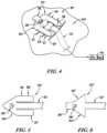
- FIG. 4is a view similar to FIG. 3 for another embodiment of the support surface of FIGS. 1 and 2 with the sensor unit woven through two slits formed in the topper of the support surface to removably couple the moisture sensor unit to the topper;
- FIG. 5is a top plan view of a first alternative sensor unit for use in the patient support apparatus of FIGS. 1 - 4 ;
- FIG. 6is a top plan view of a second alternative sensor unit for use in the patient support apparatus of FIGS. 1 - 4 ;
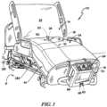
- FIG. 7is an exploded perspective view of the support surface of FIGS. 1 and 2 showing that the support surface includes a lower ticking, a number of foam bodies, a valve box, a number of inflatable bladders, a fire barrier, the topper, the sensor unit coupled to the topper, and a coverlet;
- FIG. 8is a block diagram of the patient support apparatus of FIG. 1 showing that the air box includes a user interface, a blower, and a controller that is coupled to the moisture sensor unit, the valve box and to the blower so that the controller can adjust air supplied to the topper and the inflatable bladders in response to inputs from the sensor unit;
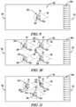
- FIG. 9is a top plan view of the support surface of FIGS. 1 and 2 with the sensor unit arranged to underlie a patient's pelvic region;
- FIG. 10is a view similar to FIG. 9 for another embodiment of the support surface with four sensor units included in the support surface arranged to underlie a patient's pelvic region and torso region;
- FIG. 11is a view similar to FIGS. 9 and 10 for another embodiment of the support surface with three sensor units included in the support surface arranged to underlie a patient's pelvic region and torso region;
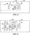
- FIG. 12is a view similar to FIGS. 9 - 11 for another embodiment of the support surface showing a sensor unit included in the support surface arranged to underlie a patient's pelvic region;
- FIG. 13is a view similar to FIGS. 9 - 12 for another embodiment of the support surface with three moisture sensor unit included in the support surface arranged to underlie a patient's pelvic region and torso region;
- FIG. 14is a perspective view of an alternative patient support apparatus in which the air box is integrated into the frame and in which a passive wireless sensor is arranged along a top side of a support surface to underlie a patient's pelvic region;
- FIG. 15is a diagrammatic view of the alternative patient support apparatus of FIG. 14 showing that frame includes a reader incorporated into a deck that underlies the passive wireless sensor included in the support surface.
- An illustrative patient support apparatus 10includes a frame 12 , a support surface 14 mounted on the frame 12 , and an air box 16 coupled to the support surface 14 .
- the support surface 14illustratively includes a topper 18 and a sensor unit 20 coupled to the topper 18 (sometimes called a cover). Both the topper 18 and the sensor unit 20 are located adjacent to a top side 24 of the support surface 14 .
- the sensor unit 20is configured to detect conditions at the interface of the support surface 14 and a patient positioned on the patient support apparatus 10 .
- the illustrative sensor unit 20is configured to detect moisture levels at the interface of the patient support apparatus 10 and a patient's skin, for example from sweat or incontinence. In some embodiments, the sensor unit 20 may be configured to detect conditions other than moisture such as temperature, pressure, or the like.
- the topper 18is configured to conduct air along the top side 24 of the support surface 14 along the interface of a patient's skin with the support surface 14 to carry away moisture from the patient as suggested in FIG. 9 .
- the air box 16is configured to take action to reduce the risk of pressure sore formation, for example triggering an alarm to request caregiver intervention or adjusting the air provided to the topper 18 .
- the sensor unit 20includes a sensor 28 and a flexible mount 30 as shown in FIGS. 2 and 3 .
- the sensor 28is configured to detect moisture and is coupled to the flexible mount 30 .
- the flexible mount 30in is a flexible polymeric film with a circuit integrated into to the flexible polymer film to provide an electrical path from the sensor 28 to the air box 16 as suggested in FIG. 3 .
- the flexible mount 30may be a flexible textile with an integrated circuit (not shown) that is sewn or adhered to the topper 18 .
- Illustrative textiles with integrated power and data circuitsare available from Weel Technologies of Guangdong, China.
- the compliance of flexible mount 30 included in the sensor unit 20may make lying on the sensor unit 20 more comfortable for a patient lying on the support surface 14 than if the sensor unit 20 included other rigid components and/or connectors.
- the flexible mount 30is illustratively shaped to include a stem portion 32 , a retention portion 34 , and a tab portion 36 as shown, for example, in FIG. 3 .
- the stem portion 32is sized to extend from the retention portion 34 to the air box 16 .
- the retention portion 34is U-shaped with two legs 37 , 38 located on opposite sides of the stem portion 32 that are interconnected by an arcuate cross-member 39 as shown in FIG. 3 .
- the cross-member 39 of the retention portion 34intersects the stem portion 32 as shown in FIG. 3 .
- the sensor 28is coupled the retention portion 34 .
- the tab portion 36illustratively extends from the retention portion 34 away from the stem portion 32 .
- the stem portion 32When the sensor unit 20 is coupled to the topper 18 , the stem portion 32 is inserted under a top layer 40 of the topper 18 through a slit 51 formed in the top layer 40 of the topper 18 as shown in FIG. 3 .
- the retention portion 34remains above the top layer 40 of the topper 18 and engages the top layer 40 along the slit 51 to retain the sensor 28 of the sensor unit 20 at a predetermined location relative to the topper 18 as suggested in FIGS. 2 and 3 .
- the stem portion 32may be woven through three slits 51 ′, 52 ′, 53 ′ formed in a top layer 40 ′ of a topper 18 ′ as shown in FIG. 4 .
- the sensor unit 20may be coupled to other sheets or covers extending over at least a portion of the top side 24 of the support surface 14 via insertion of the stem portion 32 through a slit formed in the cover.
- Coupling of the sensor unit 20 to the topper 18 via insertion of the stem portion 32 into the slit 51 until further insertion is blocked by contact of the retention portion 34 with the topper 18 as suggested in FIGS. 2 and 3allows for predetermined placement of the sensor 28 relative to the topper 20 .
- Providing repeatable placement of the sensor 28 during couplingallows for repeated removal and recoupling of the sensor unit 20 by users.
- the sensor unit 20may be removed for regular washing of the topper 18 so that the sensor 28 and the flexible mount 30 are not exposed to water or cleaning chemicals.
- the first alternative sensor unit 20 ′is substantially similar to sensor unit 20 except that the retention portion 34 ′ is arrow-shaped with two legs 37 ′, 38 ′ on either side of the stem 32 ′ interconnected by a triangular cross-member 39 ′ as shown in FIG. 5 . Further, the first alternative sensor unit 20 ′ does not include a tab.
- the second alternative sensor unit 20 ′′is also similar to sensor unit 20 except that retention portion 34 ′′ is triangular as shown in FIG. 6 .
- the retention portion 34 ′′is illustratively sized to extend beyond the width of the slit 51 formed in the topper 18 to block the retention portion 34 ′′ and the sensor 28 ′′ of the sensor unit 20 ′′ from being pushed through the slit 51 .
- the exemplary topper 18is shown to include a middle layer 41 and a bottom layer 42 in addition to the top layer 40 .
- the top layer 40 and the bottom layer 42are illustratively sheets constructed from a vapor-permeable, liquid impermeable material. More particularly, the top layer 40 and the bottom layer 42 are illustratively sheets of urethane coated nylon available from Uretek of New Haven, Conn.
- the middle layer 41 of the topper 18is illustratively a sheet made from a three-dimensional material.
- the illustrative three-dimensional material usedis sold under the name PRESSLESS® from Bodet & Horst and is configured to maintain an air gap between the top layer 40 and the bottom layer 42 when a patient is lying on the topper 18 .
- the bottom layer 42is a sheet constructed from vapor-impermeable, liquid impermeable material. Air from the air box 16 is conducted though the middle layer 41 of the topper 18 to pull moisture away from a patient supported on the topper 18 .
- the illustrative support surface 14includes a lower ticking 44 , a valve box 45 , foam components 46 , inflatable bladders 50 , a rigid sheet 55 , and upper ticking 54 as shown in FIG. 7 .
- the lower ticking 44cooperates with the upper ticking 54 to form a cover that encases the other components of the support surface 14 .
- the valve box 45is pneumatically coupled to the inflatable bladders 50 and the topper 18 to distribute air to the bladders 50 and the topper 18 .
- the foam components 46include a foam shell 47 and a foot-section filler pad 48 as shown in FIG. 7 .
- the inflatable bladders 50include support bladders 60 and turn bladders 62 .
- the foam shell 47 , foot-section filler pad 48 , support bladders 60 , and turn bladders 62cooperate to provide a cushion 77 that supports a patient lying on the patient support apparatus 10 .
- the support surface 14may also include a coverlet (not shown) that forms a cover for the other components of the support surface 14 and/or a fire sock 58 (shown diagrammatically in FIG. 8 ) that encases the internal components of the support surface 14 .
- the air box 16includes a user interface 64 , a blower 65 , an ambient sensor unit 68 , and a controller 70 coupled to the rest of the air box components 64 , 65 , 68 .
- the user interface 64illustratively includes a number of push buttons and an LCD display that allow a user to set operating parameters of the air box 16 .
- the user interface 64may be a touch-screen display or another suitable user input device.
- the blower 65is pneumatically coupled to the valve box 45 to provide pressurized air to the inflatable bladders 50 and to the topper 18 .
- the ambient sensor unit 68is configured to detect environmental conditions including relative humidity, temperature, and pressure that is used by the controller 70 to evaluate moisture detected by the sensor unit 20 in the support surface 14 .
- the controller 70is also coupled to the sensor unit 20 and to the valve box 45 of the support surface 14 as shown in FIG. 8 .
- the air box 16may also include sensor 66 coupled to the output of the blower 65 configured to detect the temperature of the air supplied to the support surface 14 .
- the illustrative controller 70includes a memory 71 , a clock 72 , and a processor 73 .
- the memory 71is configured to hold instructions and data for use by the processor 73 .
- the clock 72is coupled to the processor 73 to provide time stamps to the processor 73 .
- the processor 73executes the instructions on the memory 71 and writes information to the memory 71 , for example, adjusting operation of the blower 65 and valve box 45 based on inputs received from the sensor unit 20 , the ambient sensor unit 68 , and the sensor 66 as proscribed by the instructions written in the memory 71 .
- the controller 70receives moisture data (and sometimes temperature data) corresponding to conditions adjacent to a patient's skin from the sensor unit 20 and moisture data (and sometimes temperature data) corresponding to atmospheric conditions from the ambient sensor unit 68 . Based on the received data, the controller 70 determines a risk level for developing bed sores.
- Corrective actionsmay include displaying an alert on the user interface 64 , sending an alert to a caregiver via a nurse call (or similar) system, and/or adjusting the operation of the blower 65 and the valve box 45 to increase air flow through the topper 18 , to change the pressure in the support bladders 60 , and/or to start lateral rotation of the patient using the turn bladders 62 .
- the frame 12includes a base 81 and a deck 83 as shown in FIGS. 1 and 8 .
- the base 81supports the deck 83 and the support surface 14 above a floor 11 .
- the deck 83underlies the support surface 14 and is reconfigurable to a plurality of positions including a lie-flat position and a sitting-up position (shown in FIG. 1 ).
- the air box 16may be integrated into the frame 12 as suggested in FIGS. 14 and 15 .
- FIG. 9a top view of topper 18 and the sensor unit 20 showing that the sensor 28 of the sensor unit 20 (and the slit 51 ) is located between a head end 75 and a foot end 76 of the topper 18 .
- a detection zone 78 corresponding to an exemplary area of effectiveness for the sensor unit 20is drawn around the sensor 28 .
- the detection zone 78is arranged to lie under a patient's pelvic region when the patient is lying or sitting on the topper 18 .
- a series of flow lines 80indicate that flow through the topper 18 originates across the entire width of the topper 18 near the foot end 76 of the topper 18 and moves toward the head end 75 of the topper 18 .
- FIGS. 10 - 11alternative embodiments including more than one sensor units 20 coupled to the topper 18 are shown.
- FIG. 10shows an alternative arrangement with four sensor units 20 arranged in a rectangle to detect moisture under a patient's pelvic region and a patient's torso region.
- FIG. 11shows an alternative arrangement with three sensor units 20 arranged in a triangle to detect moisture under a patient's pelvic region and a patient's torso region.
- FIGS. 12 - 13alternative embodiments including sensor unit(s) 20 coupled to an alternative topper 118 are shown.
- FIG. 12shows a single sensor unit 20 arranged to detect moisture under a patient's pelvic region.
- FIG. 13shows an alternative arrangement similar to the arrangement in FIG. 12 with three sensor units 20 arranged in a line to detect moisture under a patient's pelvic region and a patient's torso region.
- the alternative topper 118 shown in FIGS. 12 and 13is configured to include an actively cooled region 182 and a passively cooled region 184 .
- the sensor(s) 28 of sensor unit(s) 20are illustratively arranged over the actively cooled region 182 of the alternative topper 118 .
- air provided by the air box 16is introduced into the actively cooled region 182 at origination points 80 , 81 adjacent to a patient's pelvic region and a patient's torso region.
- the passively cooled region 184is pneumatically separated from the actively cooled region 182 and air flow in the passively cooled region 184 is driven by temperature differences between a patient's body overlaying the topper 118 .
- the alternative topper 118is further described in U.S. Application No. 61/770,704 filed Feb. 28, 2013, which is hereby incorporated in its entirety by reference herein.
- the support bladders 60are illustratively vertically-oriented column-shaped bladders as shown in FIG. 7 .
- the bladders 60are configured be inflated or deflated to increase or decrease the firmness of the support surface under different parts of a patient laying on the support surface 14 .
- pressure in individual support bladders 60may be adjusted by the controller 70 in response to moisture information received from the sensor unit(s) 20 .
- FIG. 14An alternative patient support apparatus 210 is shown in FIG. 14 .
- the patient support apparatus 210is substantially similar to the patient support apparatus 10 shown in FIGS. 1 - 3 and 7 - 9 which is described herein. Accordingly, similar reference numbers in the 200 series (e.g., reference numbers 244 , 246 , 254 , 255 , 258 , 266 , 272 , 273 and 281 ) indicate features that are common between the patient support apparatus 10 and the patient support apparatus 210 .
- the description of the patient support apparatus 10is hereby incorporated by reference to apply to the patient support apparatus 210 except where it conflicts with the description and drawings of the patient support apparatus 210 .
- the patient support apparatus 210includes a wireless sensor unit 290 rather than a sensor unit 20 as shown in FIGS. 14 and 15 .
- the sensor unit 290is illustratively adhered to the top layer 254 of the topper 218 to detect moisture levels on the patient support apparatus 10 near a patient's skin, for example from sweat or incontinence. In some embodiments, the sensor unit 290 may also (or alternatively) detect temperature near the patient's skin.
- the wireless sensor unit 290is illustratively a passive sensor that is not wired for power and does not include an internal power source. Rather, the sensor unit 290 is powered wirelessly by a reader 292 incorporated into the frame 212 underlying the support surface 214 as shown in FIGS. 14 and 15 .
- the reader 292is illustratively integrated into the deck 283 of the frame 212 and is arranged to underlie the wireless sensor unit 290 .
- the reader 292is coupled to the controller 270 for communication with the controller 270 included in the air box 216 .
- the reader 292is configured to wirelessly power the wireless sensor unit 290 and to receive moisture data from the wireless sensor unit 290 while the patient support apparatus 10 is in use.
- the air box 216is illustratively integrated with the frame 212 , as shown in FIGS. 14 and 15 , but in some embodiments may be independent of the frame 212 as suggested in FIG. 1 . Aside from integration with the frame 212 , the air box 216 is similar to air box 16 and provides air to the topper 218 along with pressure control air to the inflatable bladders included in the support surface 214 .
- controller 270is configured to adjust operation the bed based on data from sensors located along the top side 224 of the support surface 214 and spaced apart from the support surface 214 .
- the controller 270receives moisture data (and sometimes temperature data) corresponding to conditions adjacent to a patient's skin from the wireless sensor unit 290 and moisture data (and sometimes temperature data) corresponding to atmospheric conditions from the ambient sensor unit 268 . Based on the received data, the controller 270 determines a risk level for developing bed sores.
- Corrective actionsmay include displaying an alert on the user interface 264 , sending an alert to a caregiver via a nurse call (or similar) system, and/or adjusting the operation of the blower 265 and the valve box 245 to increase air flow through the topper 218 , to change the pressure in the support bladders 260 , and/or to start lateral rotation of the patient using the turn bladders 262 .
Landscapes
- Health & Medical Sciences (AREA)
- Nursing (AREA)
- Life Sciences & Earth Sciences (AREA)
- Animal Behavior & Ethology (AREA)
- General Health & Medical Sciences (AREA)
- Public Health (AREA)
- Veterinary Medicine (AREA)
- Invalid Beds And Related Equipment (AREA)
Abstract
Description
Claims (20)
Priority Applications (1)
| Application Number | Priority Date | Filing Date | Title |
|---|---|---|---|
| US17/398,312US11684529B2 (en) | 2013-02-28 | 2021-08-10 | Mattress cover sensor method |
Applications Claiming Priority (4)
| Application Number | Priority Date | Filing Date | Title |
|---|---|---|---|
| US201361770679P | 2013-02-28 | 2013-02-28 | |
| US14/190,972US9333136B2 (en) | 2013-02-28 | 2014-02-26 | Sensors in a mattress cover |
| US15/090,715US20160213539A1 (en) | 2013-02-28 | 2016-04-05 | Sensors in a mattress cover |
| US17/398,312US11684529B2 (en) | 2013-02-28 | 2021-08-10 | Mattress cover sensor method |
Related Parent Applications (1)
| Application Number | Title | Priority Date | Filing Date |
|---|---|---|---|
| US15/090,715ContinuationUS20160213539A1 (en) | 2013-02-28 | 2016-04-05 | Sensors in a mattress cover |
Publications (2)
| Publication Number | Publication Date |
|---|---|
| US20210361502A1 US20210361502A1 (en) | 2021-11-25 |
| US11684529B2true US11684529B2 (en) | 2023-06-27 |
Family
ID=50179509
Family Applications (3)
| Application Number | Title | Priority Date | Filing Date |
|---|---|---|---|
| US14/190,972ActiveUS9333136B2 (en) | 2013-02-28 | 2014-02-26 | Sensors in a mattress cover |
| US15/090,715AbandonedUS20160213539A1 (en) | 2013-02-28 | 2016-04-05 | Sensors in a mattress cover |
| US17/398,312Active2034-07-12US11684529B2 (en) | 2013-02-28 | 2021-08-10 | Mattress cover sensor method |
Family Applications Before (2)
| Application Number | Title | Priority Date | Filing Date |
|---|---|---|---|
| US14/190,972ActiveUS9333136B2 (en) | 2013-02-28 | 2014-02-26 | Sensors in a mattress cover |
| US15/090,715AbandonedUS20160213539A1 (en) | 2013-02-28 | 2016-04-05 | Sensors in a mattress cover |
Country Status (2)
| Country | Link |
|---|---|
| US (3) | US9333136B2 (en) |
| EP (1) | EP2772238B1 (en) |
Families Citing this family (24)
| Publication number | Priority date | Publication date | Assignee | Title |
|---|---|---|---|---|
| US20110301432A1 (en)* | 2010-06-07 | 2011-12-08 | Riley Carl W | Apparatus for supporting and monitoring a person |
| US9420895B2 (en)* | 2009-12-17 | 2016-08-23 | Stryker Corporation | Patient support |
| US9333136B2 (en) | 2013-02-28 | 2016-05-10 | Hill-Rom Services, Inc. | Sensors in a mattress cover |
| WO2016146889A1 (en)* | 2015-03-13 | 2016-09-22 | Emfit Oy | Mattress for resting or sleeping of a person |
| US11559421B2 (en) | 2015-06-25 | 2023-01-24 | Hill-Rom Services, Inc. | Protective dressing with reusable phase-change material cooling insert |
| US10765577B2 (en) | 2015-06-30 | 2020-09-08 | Hill-Rom Services, Inc. | Microclimate system for a patient support apparatus |
| US10489661B1 (en) | 2016-03-08 | 2019-11-26 | Ocuvera LLC | Medical environment monitoring system |
| US10314528B2 (en)* | 2016-05-20 | 2019-06-11 | American Sterilizer Company | Patient support pad |
| US20180000633A1 (en)* | 2016-07-01 | 2018-01-04 | Hill-Rom Services, Inc. | Microclimate management system with wireless sensors |
| US10600204B1 (en) | 2016-12-28 | 2020-03-24 | Ocuvera | Medical environment bedsore detection and prevention system |
| US11172892B2 (en) | 2017-01-04 | 2021-11-16 | Hill-Rom Services, Inc. | Patient support apparatus having vital signs monitoring and alerting |
| US10945679B2 (en) | 2017-01-31 | 2021-03-16 | Welch Allyn, Inc. | Modular monitoring smart bed |
| US10238561B2 (en) | 2017-06-22 | 2019-03-26 | Piyush Sheth | System and method for treating and preventing pressure sores in bedridden patients |
| US10797524B2 (en) | 2017-10-24 | 2020-10-06 | Stryker Corporation | Techniques for power transfer through wheels of a patient support apparatus |
| US11394252B2 (en) | 2017-10-24 | 2022-07-19 | Stryker Corporation | Power transfer system with patient support apparatus and power transfer device to transfer power to the patient support apparatus |
| US11389357B2 (en) | 2017-10-24 | 2022-07-19 | Stryker Corporation | Energy storage device management for a patient support apparatus |
| US11139666B2 (en) | 2017-10-24 | 2021-10-05 | Stryker Corporation | Energy harvesting and propulsion assistance techniques for a patient support apparatus |
| US10910888B2 (en) | 2017-10-24 | 2021-02-02 | Stryker Corporation | Power transfer system with patient transport apparatus and power transfer device to transfer power to the patient transport apparatus |
| US11583437B2 (en) | 2018-02-06 | 2023-02-21 | Aspen Surgical Products, Inc. | Reusable warming blanket with phase change material |
| US11660242B2 (en)* | 2019-06-17 | 2023-05-30 | Morgan Leigh Miller | Portable patient turning device |
| US20210015692A1 (en)* | 2019-07-16 | 2021-01-21 | Hill-Rom Services, Inc. | Hybrid air and foam mattress with detachable air unit |
| US11348443B2 (en) | 2019-10-23 | 2022-05-31 | Gojo Industries, Inc. | Methods and systems for improved accuracy in hand-hygiene compliance |
| AT524069A1 (en) | 2020-07-30 | 2022-02-15 | Hans L Malzl | SYSTEM AND METHOD OF DETECTING SLEEP QUALITY |
| US12109160B2 (en)* | 2021-07-12 | 2024-10-08 | Sage Products, Llc | Apparatus for turning and positioning a patient with sensor elements and methods of use thereof |
Citations (166)
| Publication number | Priority date | Publication date | Assignee | Title |
|---|---|---|---|---|
| US3325799A (en) | 1964-07-13 | 1967-06-13 | Edwia Greines Cohen | Mattress alarm |
| US3631438A (en) | 1968-10-31 | 1971-12-28 | Nat Res Dev | Apnoea alarms |
| US3644950A (en) | 1969-08-01 | 1972-02-29 | Milton Roy Co | Patient support system |
| US3727606A (en) | 1970-06-12 | 1973-04-17 | Airco Inc | Apnea detection device |
| US3738702A (en) | 1972-03-15 | 1973-06-12 | Gen Motors Corp | Means for cooling and heating a seat structure |
| US3836900A (en) | 1973-01-26 | 1974-09-17 | Fleet Electronics Ltd | Recording or alarm devices |
| US3996928A (en) | 1975-05-28 | 1976-12-14 | Marx Alvin J | Patient vital-signs automated measuring apparatus |
| US4146885A (en) | 1977-10-13 | 1979-03-27 | Lawson Jr William H | Infant bed and apnea alarm |
| US4195287A (en) | 1977-11-28 | 1980-03-25 | Mathis James C | Fire and absence detection and alarm system for bed occupants |
| US4245651A (en) | 1979-03-13 | 1981-01-20 | Frost James K | Detecting body movements |
| US4422458A (en) | 1980-04-28 | 1983-12-27 | Montefiore Hospital And Medical Center, Inc. | Method and apparatus for detecting respiratory distress |
| US4481686A (en) | 1982-03-25 | 1984-11-13 | Lacoste Francois R | Air fluidized bed for therapeutic use |
| US4483029A (en) | 1981-08-10 | 1984-11-20 | Support Systems International, Inc. | Fluidized supporting apparatus |
| US4485505A (en) | 1980-08-13 | 1984-12-04 | Paul Patrick R D | Ventilating, inflatable mattress |
| US4525885A (en) | 1980-02-26 | 1985-07-02 | Mediscus Products Limited | Support appliance for mounting on a standard hospital bed |
| US4559656A (en) | 1982-12-28 | 1985-12-24 | Hill-Rom Company, Inc. | Hospital bed with a weight-distributing lever system |
| US4564965A (en) | 1984-01-17 | 1986-01-21 | Support Systems International, Inc. | Fluidized patient support system |
| US4595023A (en) | 1981-11-16 | 1986-06-17 | Kenneth Bonnet | Apparatus and method for detecting body vibrations |
| US4602643A (en) | 1984-09-14 | 1986-07-29 | Dietz Henry G | Pneumatic breathing belt sensor with minimum space maintaining tapes |
| WO1986005965A1 (en) | 1985-04-10 | 1986-10-23 | Emergent Technology Corporation | Multi-channel ventilation monitor and method |
| US4637083A (en) | 1985-03-13 | 1987-01-20 | Support Systems International, Inc. | Fluidized patient support apparatus |
| US4657026A (en) | 1986-07-14 | 1987-04-14 | Tagg James R | Apnea alarm systems |
| US4677857A (en) | 1984-11-10 | 1987-07-07 | Wabco Westinghouse Fahrzeugbremsen Gmbh | Fastener arrangement for deformation sensor |
| US4681098A (en) | 1985-10-11 | 1987-07-21 | Lee Arnold St J | System, apparatus and method for gathering physiological data |
| US4694520A (en) | 1986-01-15 | 1987-09-22 | Ssi Medical Services, Inc. | Patient support apparatus |
| JPS6315424A (en) | 1986-07-08 | 1988-01-22 | Toray Ind Inc | Passivation method of semiconductor element |
| US4747413A (en) | 1986-11-07 | 1988-05-31 | Bloch Harry S | Infant temperature measuring apparatus and methods |
| US4757825A (en) | 1985-10-31 | 1988-07-19 | Diamond Research Group, Inc. | Cardio-pulmonary activity monitor |
| US4799276A (en) | 1986-09-15 | 1989-01-24 | Ehud Kadish | Body rest with means for preventing pressure sores |
| US4838309A (en) | 1985-12-30 | 1989-06-13 | Ssi Medical Services, Inc. | Variable flow gas valve |
| US4907132A (en) | 1988-03-22 | 1990-03-06 | Lumitex, Inc. | Light emitting panel assemblies and method of making same |
| US4907845A (en) | 1988-09-16 | 1990-03-13 | Salomon Sa | Bed patient monitoring system |
| US4934468A (en) | 1987-12-28 | 1990-06-19 | Hill-Rom Company, Inc. | Hospital bed for weighing patients |
| US4935968A (en) | 1985-05-10 | 1990-06-26 | Mediscus Products, Ltd. | Patient support appliances |
| US4942635A (en) | 1988-12-20 | 1990-07-24 | Ssi Medical Services, Inc. | Dual mode patient support system |
| US4949412A (en) | 1986-11-05 | 1990-08-21 | Air Plus, Inc. | Closed loop feedback air supply for air support beds |
| US4949414A (en) | 1989-03-09 | 1990-08-21 | Ssi Medical Services, Inc. | Modular low air loss patient support system and methods for automatic patient turning and pressure point relief |
| US4971065A (en) | 1985-02-11 | 1990-11-20 | Pearce Stephen D | Transducer for detecting apnea |
| US5010772A (en) | 1986-04-11 | 1991-04-30 | Purdue Research Foundation | Pressure mapping system with capacitive measuring pad |
| US5016304A (en) | 1988-03-29 | 1991-05-21 | Redactron B.V. | Fluidized bed with moisture removing means |
| US5052067A (en) | 1989-03-09 | 1991-10-01 | Ssi Medical Services, Inc. | Bimodal system for pressurizing a low air loss patient support |
| US5057819A (en) | 1990-04-27 | 1991-10-15 | Valenti James J | Alarmed safety cushion |
| US5060174A (en) | 1990-04-18 | 1991-10-22 | Biomechanics Corporation Of America | Method and apparatus for evaluating a load bearing surface such as a seat |
| DE4018953A1 (en) | 1990-05-04 | 1992-01-23 | Augustin Hans Ulrich | Disposable intermediate layer with moisture sensor and mfg. process - has absorbent layer with film backing having central hole in which sensor is located and covered with film strip |
| US5101828A (en) | 1991-04-11 | 1992-04-07 | Rutgers, The State University Of Nj | Methods and apparatus for nonivasive monitoring of dynamic cardiac performance |
| US5117518A (en) | 1988-03-14 | 1992-06-02 | Huntleigh Technology, Plc | Pressure controller |
| US5170364A (en) | 1990-12-06 | 1992-12-08 | Biomechanics Corporation Of America | Feedback system for load bearing surface |
| US5182826A (en) | 1989-03-09 | 1993-02-02 | Ssi Medical Services, Inc. | Method of blower control |
| US5184112A (en) | 1991-09-11 | 1993-02-02 | Gaymar Industries, Inc. | Bed patient position monitor |
| US5276432A (en) | 1992-01-15 | 1994-01-04 | Stryker Corporation | Patient exit detection mechanism for hospital bed |
| US5493742A (en) | 1994-05-10 | 1996-02-27 | Lake Medical Products, Inc. | Ventilating air mattress with an inflating quilted pad |
| US5539942A (en) | 1993-12-17 | 1996-07-30 | Melou; Yves | Continuous airflow patient support with automatic pressure adjustment |
| US5588167A (en) | 1991-11-13 | 1996-12-31 | Ssi Medical Services, Inc. | Apparatus and method for managing waste from patient care maintenance and treatment |
| US5664270A (en) | 1994-07-19 | 1997-09-09 | Kinetic Concepts, Inc. | Patient interface system |
| US5794288A (en) | 1996-06-14 | 1998-08-18 | Hill-Rom, Inc. | Pressure control assembly for an air mattress |
| US5800480A (en) | 1996-08-30 | 1998-09-01 | Augustine Medical, Inc. | Support apparatus with a plurality of thermal zones providing localized cooling |
| US5802611A (en) | 1997-11-18 | 1998-09-08 | Mckenzie; Melody | Releasable clothing with temperature sensor for bedridden patients |
| EP0862901A1 (en) | 1997-03-05 | 1998-09-09 | Ohmeda Inc. | Thermoelectric infant mattress |
| US5815864A (en) | 1996-04-02 | 1998-10-06 | Sytron Corporation | Microprocessor controller and method of initializing and controlling low air loss floatation mattress |
| US5829081A (en) | 1993-11-09 | 1998-11-03 | Teksource, Lc | Cushioning device formed from separate reshapable cells |
| US5873137A (en) | 1996-06-17 | 1999-02-23 | Medogar Technologies | Pnuematic mattress systems |
| US5881410A (en) | 1994-04-28 | 1999-03-16 | Teikoku Hormone Mfg. Co., Ltd. | Air mat for operation bed |
| US5934280A (en) | 1996-07-23 | 1999-08-10 | Support Systems International Industries | Method and a device having a tap-fed heel support region |
| US5964720A (en) | 1996-11-29 | 1999-10-12 | Adaptivity Devices Ltd. | Method and system for monitoring the physiological condition of a patient |
| US6011477A (en) | 1997-07-23 | 2000-01-04 | Sensitive Technologies, Llc | Respiration and movement monitoring system |
| US6009580A (en) | 1996-12-23 | 2000-01-04 | Support Systems International Industries | Method and apparatus for supporting an element to be supported, in particular the body of a patient, making it possible to support said element at a predetermined float line |
| US6034526A (en) | 1996-07-23 | 2000-03-07 | Support Systems International Industries | Apparatus for controlling the inflation pressure of a mattress in response to deformation of the mattress using impedance measurement |
| US6052049A (en) | 1996-09-13 | 2000-04-18 | Cts Corporation | Flexible film with a non-tensioned electrical circuit mounted thereon |
| WO2000024353A1 (en) | 1998-10-28 | 2000-05-04 | Hill-Rom, Inc. | Force optimization surface apparatus and method |
| US6067019A (en) | 1996-11-25 | 2000-05-23 | Hill-Rom, Inc. | Bed exit detection apparatus |
| US6079068A (en) | 1996-12-23 | 2000-06-27 | Support Systems International Industries | Method and apparatus for supporting an element to be supported, in particular the body of a patient, the apparatus having a support device independent from the control device |
| US6080690A (en) | 1998-04-29 | 2000-06-27 | Motorola, Inc. | Textile fabric with integrated sensing device and clothing fabricated thereof |
| US6094762A (en) | 1998-02-09 | 2000-08-01 | Hill-Rom Industries, S.A. | Method and apparatus for supporting an element to be supported, in particular the body of a patient, and having an integrated system for achieving pressure equilibrium dynamically and automatically |
| US6208250B1 (en) | 1999-03-05 | 2001-03-27 | Hill-Rom, Inc. | Patient position detection apparatus for a bed |
| US6212718B1 (en) | 1998-03-31 | 2001-04-10 | Hill-Rom, Inc | Air-over-foam mattress |
| US6386051B1 (en) | 1999-03-15 | 2002-05-14 | Denso Corporation | Load detection sensor unit for bedding with single output line |
| US20030033675A1 (en)* | 2001-08-03 | 2003-02-20 | Angela Solesbee | Medical procedure table pad |
| US6560804B2 (en) | 1997-11-24 | 2003-05-13 | Kci Licensing, Inc. | System and methods for mattress control in relation to patient distance |
| US20030210144A1 (en) | 2002-03-08 | 2003-11-13 | Reinhold Ott | Sensor element for a monitoring device |
| US6719708B1 (en) | 1999-10-19 | 2004-04-13 | Thomas Hilfen Hilbeg Gmbh & Co. Kommanditgesellschaft | Device and method for measuring values from a person lying down, and pressure sensor |
| US6721980B1 (en) | 1998-10-28 | 2004-04-20 | Hill-Fom Services, Inc. | Force optimization surface apparatus and method |
| US6730115B1 (en) | 1996-05-16 | 2004-05-04 | Kci Licensing, Inc. | Cooling system |
| US6739006B2 (en) | 1997-11-07 | 2004-05-25 | Hill-Rom Services, Inc. | Head section support for a surgical table apparatus |
| WO2004045407A1 (en) | 2002-11-20 | 2004-06-03 | Hoana Medical, Inc. | Device and method for passive patient monitoring |
| US6813790B2 (en) | 2002-02-28 | 2004-11-09 | Gaymar Industries, Inc. | Self-adjusting cushioning device |
| US20050027416A1 (en) | 2003-07-18 | 2005-02-03 | Basir Otman Adam | Occupant heartbeat detection and monitoring system |
| US20050076715A1 (en)* | 2003-10-13 | 2005-04-14 | Kuklis Matthew M. | Shear sensor apparatus |
| US6923571B2 (en) | 2002-02-08 | 2005-08-02 | Compliance Laboratories, L.L.C. | Temperature-based sensing device for detecting presence of body part |
| US20050168341A1 (en) | 2000-05-05 | 2005-08-04 | Hill-Rom Services, Inc. | Caregiver and equipment monitoring and control system |
| US20050190068A1 (en) | 2004-02-18 | 2005-09-01 | Gentry Jason M. | Method and system for integrating a passive sensor array with a mattress for patient monitoring |
| US20050190062A1 (en) | 2003-12-04 | 2005-09-01 | Sullivan Patrick K. | Intelligent medical vigilance system |
| US20050288749A1 (en) | 2004-06-08 | 2005-12-29 | Lachenbruch Charles A | Heat wick for skin cooling |
| US6984207B1 (en) | 1999-09-14 | 2006-01-10 | Hoana Medical, Inc. | Passive physiological monitoring (P2M) system |
| US20060021141A1 (en) | 2004-06-29 | 2006-02-02 | Kiyoteru Shima | Human body cover with medical accident prevention function |
| WO2006023479A2 (en) | 2004-08-16 | 2006-03-02 | Hill-Rom Services, Inc. | Dynamic cellular person support surface |
| US20060101581A1 (en) | 2004-10-29 | 2006-05-18 | Blanchard Frederick W | Patient support apparatus |
| US20060109091A1 (en) | 2004-11-24 | 2006-05-25 | Elesys North America Inc. | Flexible occupant sensor and method of use |
| US7077810B2 (en) | 2004-02-05 | 2006-07-18 | Earlysense Ltd. | Techniques for prediction and monitoring of respiration-manifested clinical episodes |
| US20060162074A1 (en) | 2003-02-04 | 2006-07-27 | Gaby Bader | Device and method for controlling physical properties of a bed |
| US7090648B2 (en) | 2000-09-28 | 2006-08-15 | Non-Invasive Monitoring Systems, Inc. | External addition of pulses to fluid channels of body to release or suppress endothelial mediators and to determine effectiveness of such intervention |
| US20060179952A1 (en) | 2005-02-17 | 2006-08-17 | The Boeing Company | Piezoelectric sensor, sensor array, and associated method for measuring pressure |
| US7107642B2 (en) | 2003-03-12 | 2006-09-19 | Jetta Company Limited | Adjustable mattress and pillow system |
| US7111346B2 (en) | 2002-05-15 | 2006-09-26 | Non-Invasive Monitoring Systems, Inc. | Reciprocating movement platform for the external addition of pulses of the fluid channels of a subject |
| WO2007008831A2 (en) | 2005-07-08 | 2007-01-18 | Hill-Rom, Inc. | Control unit for patient support |
| WO2007016054A2 (en) | 2005-07-26 | 2007-02-08 | Hill-Rom Services, Inc. | System and method of controlling an air mattress |
| US20070057665A1 (en) | 2004-02-24 | 2007-03-15 | Peter Borst | Sensor holder and method for the production thereof |
| US20070083125A1 (en) | 2005-08-31 | 2007-04-12 | Kabushiki Kaisha Toshiba | Apparatus and method of measuring biological information |
| EP1779824A2 (en) | 2001-09-11 | 2007-05-02 | Hill-Rom Services, Inc. | Thermo-regulating patient support structure |
| US7219380B2 (en) | 2005-04-22 | 2007-05-22 | R&D Products, Llc | Multicompartmented air mattress |
| US20070118038A1 (en) | 2005-11-23 | 2007-05-24 | Vital Sensors Inc. | Implantable device for telemetric measurement of blood pressure/temperature within the heart |
| US20070118054A1 (en) | 2005-11-01 | 2007-05-24 | Earlysense Ltd. | Methods and systems for monitoring patients for clinical episodes |
| US20070118993A1 (en) | 2005-11-28 | 2007-05-31 | Jason Bates | Inflatable incontinence bed pad |
| US20070135878A1 (en) | 2003-06-13 | 2007-06-14 | Lachenbruch Charles A | Self-powered steady-state skin-cooling support surfaces |
| US7242306B2 (en) | 2001-05-08 | 2007-07-10 | Hill-Rom Services, Inc. | Article locating and tracking apparatus and method |
| US7248933B2 (en) | 2001-05-08 | 2007-07-24 | Hill-Rom Services, Inc. | Article locating and tracking system |
| US20070176092A1 (en) | 1999-07-21 | 2007-08-02 | Sionex Corporation | Method and apparatus for enhanced ion mobility based sample analysis using various analyzer configurations |
| US7253366B2 (en) | 2004-08-09 | 2007-08-07 | Hill-Rom Services, Inc. | Exit alarm for a hospital bed triggered by individual load cell weight readings exceeding a predetermined threshold |
| US20070241895A1 (en) | 2006-04-13 | 2007-10-18 | Morgan Kelvin L | Noise reduction for flexible sensor material in occupant detection |
| US20070261548A1 (en) | 2006-05-11 | 2007-11-15 | Kci Licensing, Inc., Legal Department, Intellectual Property | Multi-layered support system |
| US7296312B2 (en) | 2002-09-06 | 2007-11-20 | Hill-Rom Services, Inc. | Hospital bed |
| US7306564B2 (en) | 2003-11-26 | 2007-12-11 | Denso Corporation | Breath monitor |
| US7314451B2 (en) | 2005-04-25 | 2008-01-01 | Earlysense Ltd. | Techniques for prediction and monitoring of clinical episodes |
| US7315535B2 (en) | 2001-03-30 | 2008-01-01 | Hill-Rom Services, Inc. | Information management system for bed data |
| US7316171B2 (en) | 2002-11-07 | 2008-01-08 | Cb System Co. | Biosignal intensity measuring method, bedding state judging method, and bedding state monitoring device |
| US7319386B2 (en) | 2004-08-02 | 2008-01-15 | Hill-Rom Services, Inc. | Configurable system for alerting caregivers |
| US20080015665A1 (en) | 2004-02-10 | 2008-01-17 | Lachenbruch Charles A | Heat wick for skin cooling |
| US20080028533A1 (en) | 2006-08-04 | 2008-02-07 | Stacy Richard B | Patient Support |
| US20080079697A1 (en) | 2006-08-01 | 2008-04-03 | Dong-Ju Lee | Display device and manufacturing method thereof |
| US20080109964A1 (en) | 2006-11-14 | 2008-05-15 | Thierry Flocard | Control System For Hospital Bed Mattress |
| US20080169931A1 (en) | 2007-01-17 | 2008-07-17 | Hoana Medical, Inc. | Bed exit and patient detection system |
| US20080269625A1 (en) | 2004-02-05 | 2008-10-30 | Earlysense Ltd. | Prediction and monitoring of clinical episodes |
| US20080275349A1 (en) | 2007-05-02 | 2008-11-06 | Earlysense Ltd. | Monitoring, predicting and treating clinical episodes |
| US7459645B2 (en) | 2003-12-12 | 2008-12-02 | Hill-Rom Services, Inc. | Seat force sensor for a patient support |
| US7472439B2 (en) | 2005-02-23 | 2009-01-06 | Stryker Canadian Management, Inc. | Hospital patient support |
| US20090193573A1 (en)* | 2008-02-05 | 2009-08-06 | Minoru Nakamura | Detection system for toilet unit for use in a supine position |
| US20090217460A1 (en) | 2005-07-08 | 2009-09-03 | Bobey John A | Patient support |
| US7629890B2 (en) | 2003-12-04 | 2009-12-08 | Hoana Medical, Inc. | System and methods for intelligent medical vigilance with bed exit detection |
| US20100043143A1 (en) | 2007-04-30 | 2010-02-25 | Span-America Medical Systems, Inc. | Low air loss moisture control mattress overlay |
| US20100101026A1 (en) | 2008-10-13 | 2010-04-29 | George Papaioannou | Adaptable surface for use in beds and chairs to reduce occurrence of pressure ulcers |
| US20100101022A1 (en) | 2008-10-24 | 2010-04-29 | Carl William Riley | Apparatuses for supporting and monitoring a person |
| US7787726B2 (en) | 2007-03-14 | 2010-08-31 | General Electric Company | Temperature sensing fabric |
| US20100274331A1 (en) | 2009-04-28 | 2010-10-28 | Rachel Williamson | Microclimate management system |
| US7825814B2 (en) | 2002-07-17 | 2010-11-02 | Hill-Rom Services, Inc. | Bed occupant monitoring system |
| US20110024076A1 (en)* | 2008-04-15 | 2011-02-03 | Hill-Rom Services, Inc. | Microclimate management system |
| EP2298264A2 (en) | 2009-09-18 | 2011-03-23 | Hill-Rom Services, Inc. | Patient support surface index control |
| US20110113561A1 (en) | 2009-11-18 | 2011-05-19 | Douglas Stephen L | Method and apparatus for sensing foot retraction in a mattress replacement system |
| US20110163885A1 (en) | 2005-08-10 | 2011-07-07 | Craig Poulos | Adjustable therapeutic mattress |
| US20110247143A1 (en) | 2008-04-15 | 2011-10-13 | Richards Sandy M | Temperature and moisture regulating topper for non-powered person-support surfaces |
| US8087113B2 (en) | 2005-05-12 | 2012-01-03 | Hunteigh Technology Limited | Inflatable support |
| US20120172959A1 (en) | 2011-01-05 | 2012-07-05 | Lachenbruch Charles A | Cooling System for an Occupant of an Occupant Support and a Cooling Garment |
| US20120174322A1 (en) | 2005-06-10 | 2012-07-12 | Skinner Andrew F | Control for pressurized bladder in a patient support apparatus |
| US20120191164A1 (en) | 2011-01-26 | 2012-07-26 | Gander Nicholas M | Radiant heating apparatus and method for therapeutic heating |
| EP2508128A1 (en) | 2011-04-08 | 2012-10-10 | Hill-Rom Services, Inc. | Person support apparatus with activity and mobility sensing |
| US8327477B2 (en) | 2009-06-29 | 2012-12-11 | Hill-Rom Services, Inc. | Localized microclimate management |
| US20130013022A1 (en) | 2010-03-19 | 2013-01-10 | De Oliveira Barroso Junior Ubirajara | Enuresis Electroconditioner |
| US20130019405A1 (en) | 2011-07-19 | 2013-01-24 | Joseph Flanagan | Moisture detection system |
| US20130135137A1 (en) | 2010-08-12 | 2013-05-30 | Koninklijke Philips Electronics N.V. | Device, system and method for measuring vital signs |
| US8525679B2 (en) | 2009-09-18 | 2013-09-03 | Hill-Rom Services, Inc. | Sensor control for apparatuses for supporting and monitoring a person |
| US20130269106A1 (en) | 2007-10-15 | 2013-10-17 | Gentherm Incorporated | Climate controlled bed assembly with intermediate layer |
| EP2667313A2 (en) | 2012-05-22 | 2013-11-27 | Hill-Rom Services, Inc. | Adverse condition detection, assessment, and response system |
| US20140018205A1 (en) | 2012-07-12 | 2014-01-16 | Nissan Motor Co., Ltd. | Drive force distributing apparatus |
| US8672853B2 (en) | 2010-06-15 | 2014-03-18 | Bam Labs, Inc. | Pressure sensor for monitoring a subject and pressure sensor with inflatable bladder |
| US20140182051A1 (en) | 2011-01-21 | 2014-07-03 | Unicharm Corporation | Urine disposal device |
| US20140237722A1 (en) | 2013-02-28 | 2014-08-28 | Hill-Rom Services, Inc. | Sensors in a matress cover |
| US20150059100A1 (en) | 2013-09-05 | 2015-03-05 | Stryker Corporation | Patient support |
| US9149211B2 (en)* | 2008-10-24 | 2015-10-06 | Sensimat Systems Inc. | Monitoring system for pressure sore prevention |
- 2014
- 2014-02-26USUS14/190,972patent/US9333136B2/enactiveActive
- 2014-02-27EPEP14156940.0Apatent/EP2772238B1/enactiveActive
- 2016
- 2016-04-05USUS15/090,715patent/US20160213539A1/ennot_activeAbandoned
- 2021
- 2021-08-10USUS17/398,312patent/US11684529B2/enactiveActive
Patent Citations (190)
| Publication number | Priority date | Publication date | Assignee | Title |
|---|---|---|---|---|
| US3325799A (en) | 1964-07-13 | 1967-06-13 | Edwia Greines Cohen | Mattress alarm |
| US3631438A (en) | 1968-10-31 | 1971-12-28 | Nat Res Dev | Apnoea alarms |
| US3644950A (en) | 1969-08-01 | 1972-02-29 | Milton Roy Co | Patient support system |
| US3727606A (en) | 1970-06-12 | 1973-04-17 | Airco Inc | Apnea detection device |
| US3738702A (en) | 1972-03-15 | 1973-06-12 | Gen Motors Corp | Means for cooling and heating a seat structure |
| US3836900A (en) | 1973-01-26 | 1974-09-17 | Fleet Electronics Ltd | Recording or alarm devices |
| US3996928A (en) | 1975-05-28 | 1976-12-14 | Marx Alvin J | Patient vital-signs automated measuring apparatus |
| US4146885A (en) | 1977-10-13 | 1979-03-27 | Lawson Jr William H | Infant bed and apnea alarm |
| US4195287A (en) | 1977-11-28 | 1980-03-25 | Mathis James C | Fire and absence detection and alarm system for bed occupants |
| US4245651A (en) | 1979-03-13 | 1981-01-20 | Frost James K | Detecting body movements |
| US4525885A (en) | 1980-02-26 | 1985-07-02 | Mediscus Products Limited | Support appliance for mounting on a standard hospital bed |
| US4422458A (en) | 1980-04-28 | 1983-12-27 | Montefiore Hospital And Medical Center, Inc. | Method and apparatus for detecting respiratory distress |
| US4485505A (en) | 1980-08-13 | 1984-12-04 | Paul Patrick R D | Ventilating, inflatable mattress |
| US4483029A (en) | 1981-08-10 | 1984-11-20 | Support Systems International, Inc. | Fluidized supporting apparatus |
| US4595023A (en) | 1981-11-16 | 1986-06-17 | Kenneth Bonnet | Apparatus and method for detecting body vibrations |
| US4481686A (en) | 1982-03-25 | 1984-11-13 | Lacoste Francois R | Air fluidized bed for therapeutic use |
| US4559656A (en) | 1982-12-28 | 1985-12-24 | Hill-Rom Company, Inc. | Hospital bed with a weight-distributing lever system |
| US4564965A (en) | 1984-01-17 | 1986-01-21 | Support Systems International, Inc. | Fluidized patient support system |
| US4602643A (en) | 1984-09-14 | 1986-07-29 | Dietz Henry G | Pneumatic breathing belt sensor with minimum space maintaining tapes |
| US4677857A (en) | 1984-11-10 | 1987-07-07 | Wabco Westinghouse Fahrzeugbremsen Gmbh | Fastener arrangement for deformation sensor |
| US4971065A (en) | 1985-02-11 | 1990-11-20 | Pearce Stephen D | Transducer for detecting apnea |
| US4637083A (en) | 1985-03-13 | 1987-01-20 | Support Systems International, Inc. | Fluidized patient support apparatus |
| WO1986005965A1 (en) | 1985-04-10 | 1986-10-23 | Emergent Technology Corporation | Multi-channel ventilation monitor and method |
| US4935968A (en) | 1985-05-10 | 1990-06-26 | Mediscus Products, Ltd. | Patient support appliances |
| US4681098A (en) | 1985-10-11 | 1987-07-21 | Lee Arnold St J | System, apparatus and method for gathering physiological data |
| US4757825A (en) | 1985-10-31 | 1988-07-19 | Diamond Research Group, Inc. | Cardio-pulmonary activity monitor |
| US4838309A (en) | 1985-12-30 | 1989-06-13 | Ssi Medical Services, Inc. | Variable flow gas valve |
| US4694520A (en) | 1986-01-15 | 1987-09-22 | Ssi Medical Services, Inc. | Patient support apparatus |
| US5010772A (en) | 1986-04-11 | 1991-04-30 | Purdue Research Foundation | Pressure mapping system with capacitive measuring pad |
| JPS6315424A (en) | 1986-07-08 | 1988-01-22 | Toray Ind Inc | Passivation method of semiconductor element |
| US4657026A (en) | 1986-07-14 | 1987-04-14 | Tagg James R | Apnea alarm systems |
| US4799276A (en) | 1986-09-15 | 1989-01-24 | Ehud Kadish | Body rest with means for preventing pressure sores |
| US4949412A (en) | 1986-11-05 | 1990-08-21 | Air Plus, Inc. | Closed loop feedback air supply for air support beds |
| US4747413A (en) | 1986-11-07 | 1988-05-31 | Bloch Harry S | Infant temperature measuring apparatus and methods |
| US4934468A (en) | 1987-12-28 | 1990-06-19 | Hill-Rom Company, Inc. | Hospital bed for weighing patients |
| US5117518A (en) | 1988-03-14 | 1992-06-02 | Huntleigh Technology, Plc | Pressure controller |
| US4907132A (en) | 1988-03-22 | 1990-03-06 | Lumitex, Inc. | Light emitting panel assemblies and method of making same |
| US5016304A (en) | 1988-03-29 | 1991-05-21 | Redactron B.V. | Fluidized bed with moisture removing means |
| US4907845A (en) | 1988-09-16 | 1990-03-13 | Salomon Sa | Bed patient monitoring system |
| US4942635A (en) | 1988-12-20 | 1990-07-24 | Ssi Medical Services, Inc. | Dual mode patient support system |
| US5052067A (en) | 1989-03-09 | 1991-10-01 | Ssi Medical Services, Inc. | Bimodal system for pressurizing a low air loss patient support |
| US4949414A (en) | 1989-03-09 | 1990-08-21 | Ssi Medical Services, Inc. | Modular low air loss patient support system and methods for automatic patient turning and pressure point relief |
| US5182826A (en) | 1989-03-09 | 1993-02-02 | Ssi Medical Services, Inc. | Method of blower control |
| US5060174A (en) | 1990-04-18 | 1991-10-22 | Biomechanics Corporation Of America | Method and apparatus for evaluating a load bearing surface such as a seat |
| US5057819A (en) | 1990-04-27 | 1991-10-15 | Valenti James J | Alarmed safety cushion |
| DE4018953A1 (en) | 1990-05-04 | 1992-01-23 | Augustin Hans Ulrich | Disposable intermediate layer with moisture sensor and mfg. process - has absorbent layer with film backing having central hole in which sensor is located and covered with film strip |
| US5170364A (en) | 1990-12-06 | 1992-12-08 | Biomechanics Corporation Of America | Feedback system for load bearing surface |
| US5283735A (en) | 1990-12-06 | 1994-02-01 | Biomechanics Corporation Of America | Feedback system for load bearing surface |
| US5101828A (en) | 1991-04-11 | 1992-04-07 | Rutgers, The State University Of Nj | Methods and apparatus for nonivasive monitoring of dynamic cardiac performance |
| US5184112A (en) | 1991-09-11 | 1993-02-02 | Gaymar Industries, Inc. | Bed patient position monitor |
| US5588167A (en) | 1991-11-13 | 1996-12-31 | Ssi Medical Services, Inc. | Apparatus and method for managing waste from patient care maintenance and treatment |
| US5276432A (en) | 1992-01-15 | 1994-01-04 | Stryker Corporation | Patient exit detection mechanism for hospital bed |
| US5829081A (en) | 1993-11-09 | 1998-11-03 | Teksource, Lc | Cushioning device formed from separate reshapable cells |
| US5539942A (en) | 1993-12-17 | 1996-07-30 | Melou; Yves | Continuous airflow patient support with automatic pressure adjustment |
| US5881410A (en) | 1994-04-28 | 1999-03-16 | Teikoku Hormone Mfg. Co., Ltd. | Air mat for operation bed |
| US5493742A (en) | 1994-05-10 | 1996-02-27 | Lake Medical Products, Inc. | Ventilating air mattress with an inflating quilted pad |
| US5664270A (en) | 1994-07-19 | 1997-09-09 | Kinetic Concepts, Inc. | Patient interface system |
| US6493568B1 (en) | 1994-07-19 | 2002-12-10 | Kci Licensing, Inc. | Patient interface system |
| US5815864A (en) | 1996-04-02 | 1998-10-06 | Sytron Corporation | Microprocessor controller and method of initializing and controlling low air loss floatation mattress |
| US6730115B1 (en) | 1996-05-16 | 2004-05-04 | Kci Licensing, Inc. | Cooling system |
| US5794288A (en) | 1996-06-14 | 1998-08-18 | Hill-Rom, Inc. | Pressure control assembly for an air mattress |
| US5873137A (en) | 1996-06-17 | 1999-02-23 | Medogar Technologies | Pnuematic mattress systems |
| US5934280A (en) | 1996-07-23 | 1999-08-10 | Support Systems International Industries | Method and a device having a tap-fed heel support region |
| US6034526A (en) | 1996-07-23 | 2000-03-07 | Support Systems International Industries | Apparatus for controlling the inflation pressure of a mattress in response to deformation of the mattress using impedance measurement |
| US6033432A (en) | 1996-08-30 | 2000-03-07 | Augustine Medical, Inc. | Support apparatus with a plurality of thermal zones providing localized cooling |
| US6497720B1 (en) | 1996-08-30 | 2002-12-24 | Augustine Medical, Inc. | Support apparatus with a plurality of thermal zones providing localized cooling |
| US5800480A (en) | 1996-08-30 | 1998-09-01 | Augustine Medical, Inc. | Support apparatus with a plurality of thermal zones providing localized cooling |
| US6052049A (en) | 1996-09-13 | 2000-04-18 | Cts Corporation | Flexible film with a non-tensioned electrical circuit mounted thereon |
| US6067019A (en) | 1996-11-25 | 2000-05-23 | Hill-Rom, Inc. | Bed exit detection apparatus |
| US5964720A (en) | 1996-11-29 | 1999-10-12 | Adaptivity Devices Ltd. | Method and system for monitoring the physiological condition of a patient |
| US6009580A (en) | 1996-12-23 | 2000-01-04 | Support Systems International Industries | Method and apparatus for supporting an element to be supported, in particular the body of a patient, making it possible to support said element at a predetermined float line |
| US6079068A (en) | 1996-12-23 | 2000-06-27 | Support Systems International Industries | Method and apparatus for supporting an element to be supported, in particular the body of a patient, the apparatus having a support device independent from the control device |
| EP0862901A1 (en) | 1997-03-05 | 1998-09-09 | Ohmeda Inc. | Thermoelectric infant mattress |
| US6011477A (en) | 1997-07-23 | 2000-01-04 | Sensitive Technologies, Llc | Respiration and movement monitoring system |
| US6739006B2 (en) | 1997-11-07 | 2004-05-25 | Hill-Rom Services, Inc. | Head section support for a surgical table apparatus |
| US5802611A (en) | 1997-11-18 | 1998-09-08 | Mckenzie; Melody | Releasable clothing with temperature sensor for bedridden patients |
| US6560804B2 (en) | 1997-11-24 | 2003-05-13 | Kci Licensing, Inc. | System and methods for mattress control in relation to patient distance |
| US6094762A (en) | 1998-02-09 | 2000-08-01 | Hill-Rom Industries, S.A. | Method and apparatus for supporting an element to be supported, in particular the body of a patient, and having an integrated system for achieving pressure equilibrium dynamically and automatically |
| US6212718B1 (en) | 1998-03-31 | 2001-04-10 | Hill-Rom, Inc | Air-over-foam mattress |
| US6080690A (en) | 1998-04-29 | 2000-06-27 | Motorola, Inc. | Textile fabric with integrated sensing device and clothing fabricated thereof |
| US6721980B1 (en) | 1998-10-28 | 2004-04-20 | Hill-Fom Services, Inc. | Force optimization surface apparatus and method |
| WO2000024353A1 (en) | 1998-10-28 | 2000-05-04 | Hill-Rom, Inc. | Force optimization surface apparatus and method |
| US7330127B2 (en) | 1998-10-28 | 2008-02-12 | Hill-Rom Services, Inc. | Force optimization surface apparatus and method |
| US7515059B2 (en) | 1998-10-28 | 2009-04-07 | Hill-Rom Services, Inc. | Patient support surface with physiological sensors |
| US20080060138A1 (en) | 1998-10-28 | 2008-03-13 | Price James H | Patient support surface with physiological sensors |
| US6208250B1 (en) | 1999-03-05 | 2001-03-27 | Hill-Rom, Inc. | Patient position detection apparatus for a bed |
| US20010001235A1 (en) | 1999-03-05 | 2001-05-17 | Hill-Rom, Inc. | Bed control apparatus |
| US6386051B1 (en) | 1999-03-15 | 2002-05-14 | Denso Corporation | Load detection sensor unit for bedding with single output line |
| US20070176092A1 (en) | 1999-07-21 | 2007-08-02 | Sionex Corporation | Method and apparatus for enhanced ion mobility based sample analysis using various analyzer configurations |
| US6984207B1 (en) | 1999-09-14 | 2006-01-10 | Hoana Medical, Inc. | Passive physiological monitoring (P2M) system |
| US6719708B1 (en) | 1999-10-19 | 2004-04-13 | Thomas Hilfen Hilbeg Gmbh & Co. Kommanditgesellschaft | Device and method for measuring values from a person lying down, and pressure sensor |
| US20050168341A1 (en) | 2000-05-05 | 2005-08-04 | Hill-Rom Services, Inc. | Caregiver and equipment monitoring and control system |
| US7090648B2 (en) | 2000-09-28 | 2006-08-15 | Non-Invasive Monitoring Systems, Inc. | External addition of pulses to fluid channels of body to release or suppress endothelial mediators and to determine effectiveness of such intervention |
| US7315535B2 (en) | 2001-03-30 | 2008-01-01 | Hill-Rom Services, Inc. | Information management system for bed data |
| US7248933B2 (en) | 2001-05-08 | 2007-07-24 | Hill-Rom Services, Inc. | Article locating and tracking system |
| US7242306B2 (en) | 2001-05-08 | 2007-07-10 | Hill-Rom Services, Inc. | Article locating and tracking apparatus and method |
| US20030033675A1 (en)* | 2001-08-03 | 2003-02-20 | Angela Solesbee | Medical procedure table pad |
| EP1779824A2 (en) | 2001-09-11 | 2007-05-02 | Hill-Rom Services, Inc. | Thermo-regulating patient support structure |
| US6923571B2 (en) | 2002-02-08 | 2005-08-02 | Compliance Laboratories, L.L.C. | Temperature-based sensing device for detecting presence of body part |
| US6813790B2 (en) | 2002-02-28 | 2004-11-09 | Gaymar Industries, Inc. | Self-adjusting cushioning device |
| US20030210144A1 (en) | 2002-03-08 | 2003-11-13 | Reinhold Ott | Sensor element for a monitoring device |
| US7111346B2 (en) | 2002-05-15 | 2006-09-26 | Non-Invasive Monitoring Systems, Inc. | Reciprocating movement platform for the external addition of pulses of the fluid channels of a subject |
| US7228576B2 (en) | 2002-05-15 | 2007-06-12 | Non-Invasive Monitoring Systems, Inc. | Reciprocating movement platform for the external addition of pulses to the fluid channels of a subject |
| US7825814B2 (en) | 2002-07-17 | 2010-11-02 | Hill-Rom Services, Inc. | Bed occupant monitoring system |
| US7296312B2 (en) | 2002-09-06 | 2007-11-20 | Hill-Rom Services, Inc. | Hospital bed |
| US7316171B2 (en) | 2002-11-07 | 2008-01-08 | Cb System Co. | Biosignal intensity measuring method, bedding state judging method, and bedding state monitoring device |
| US20040111045A1 (en) | 2002-11-20 | 2004-06-10 | Hoana Technologies, Inc. | Devices and methods for passive patient monitoring |
| WO2004045407A1 (en) | 2002-11-20 | 2004-06-03 | Hoana Medical, Inc. | Device and method for passive patient monitoring |
| US20060162074A1 (en) | 2003-02-04 | 2006-07-27 | Gaby Bader | Device and method for controlling physical properties of a bed |
| US7107642B2 (en) | 2003-03-12 | 2006-09-19 | Jetta Company Limited | Adjustable mattress and pillow system |
| US20070135878A1 (en) | 2003-06-13 | 2007-06-14 | Lachenbruch Charles A | Self-powered steady-state skin-cooling support surfaces |
| US20050027416A1 (en) | 2003-07-18 | 2005-02-03 | Basir Otman Adam | Occupant heartbeat detection and monitoring system |
| US7183930B2 (en) | 2003-07-18 | 2007-02-27 | Intelligent Mechatronic Systems Inc. | Occupant heartbeat detection and monitoring system |
| US20050076715A1 (en)* | 2003-10-13 | 2005-04-14 | Kuklis Matthew M. | Shear sensor apparatus |
| US7306564B2 (en) | 2003-11-26 | 2007-12-11 | Denso Corporation | Breath monitor |
| US7629890B2 (en) | 2003-12-04 | 2009-12-08 | Hoana Medical, Inc. | System and methods for intelligent medical vigilance with bed exit detection |
| US20050190062A1 (en) | 2003-12-04 | 2005-09-01 | Sullivan Patrick K. | Intelligent medical vigilance system |
| US7304580B2 (en) | 2003-12-04 | 2007-12-04 | Hoana Medical, Inc. | Intelligent medical vigilance system |
| US7459645B2 (en) | 2003-12-12 | 2008-12-02 | Hill-Rom Services, Inc. | Seat force sensor for a patient support |
| US7714238B2 (en) | 2003-12-12 | 2010-05-11 | Hill-Rom Services, Inc. | Mattress seat force sensing method |
| US7077810B2 (en) | 2004-02-05 | 2006-07-18 | Earlysense Ltd. | Techniques for prediction and monitoring of respiration-manifested clinical episodes |
| US20080114260A1 (en) | 2004-02-05 | 2008-05-15 | Earlysense Ltd. | Techniques for prediction and monitoring of coughing-manifested clinical episodes |
| US20080269625A1 (en) | 2004-02-05 | 2008-10-30 | Earlysense Ltd. | Prediction and monitoring of clinical episodes |
| US20080015665A1 (en) | 2004-02-10 | 2008-01-17 | Lachenbruch Charles A | Heat wick for skin cooling |
| US20050190068A1 (en) | 2004-02-18 | 2005-09-01 | Gentry Jason M. | Method and system for integrating a passive sensor array with a mattress for patient monitoring |
| US20070057665A1 (en) | 2004-02-24 | 2007-03-15 | Peter Borst | Sensor holder and method for the production thereof |
| US7273490B2 (en) | 2004-06-08 | 2007-09-25 | Charles Arthur Lachenbruch | Heat wick for skin cooling |
| US20050288749A1 (en) | 2004-06-08 | 2005-12-29 | Lachenbruch Charles A | Heat wick for skin cooling |
| US20060021141A1 (en) | 2004-06-29 | 2006-02-02 | Kiyoteru Shima | Human body cover with medical accident prevention function |
| US7319386B2 (en) | 2004-08-02 | 2008-01-15 | Hill-Rom Services, Inc. | Configurable system for alerting caregivers |
| US7253366B2 (en) | 2004-08-09 | 2007-08-07 | Hill-Rom Services, Inc. | Exit alarm for a hospital bed triggered by individual load cell weight readings exceeding a predetermined threshold |
| US20060085919A1 (en) | 2004-08-16 | 2006-04-27 | Kramer Kenneth L | Dynamic cellular person support surface |
| US7409735B2 (en) | 2004-08-16 | 2008-08-12 | Hill-Rom Services, Inc. | Dynamic cellular person support surface |
| WO2006023479A2 (en) | 2004-08-16 | 2006-03-02 | Hill-Rom Services, Inc. | Dynamic cellular person support surface |
| US20060101581A1 (en) | 2004-10-29 | 2006-05-18 | Blanchard Frederick W | Patient support apparatus |
| US20060109091A1 (en) | 2004-11-24 | 2006-05-25 | Elesys North America Inc. | Flexible occupant sensor and method of use |
| US7127948B2 (en) | 2005-02-17 | 2006-10-31 | The Boeing Company | Piezoelectric sensor, sensor array, and associated method for measuring pressure |
| US20060179952A1 (en) | 2005-02-17 | 2006-08-17 | The Boeing Company | Piezoelectric sensor, sensor array, and associated method for measuring pressure |
| US7472439B2 (en) | 2005-02-23 | 2009-01-06 | Stryker Canadian Management, Inc. | Hospital patient support |
| US7219380B2 (en) | 2005-04-22 | 2007-05-22 | R&D Products, Llc | Multicompartmented air mattress |
| US7314451B2 (en) | 2005-04-25 | 2008-01-01 | Earlysense Ltd. | Techniques for prediction and monitoring of clinical episodes |
| US8087113B2 (en) | 2005-05-12 | 2012-01-03 | Hunteigh Technology Limited | Inflatable support |
| US20120174322A1 (en) | 2005-06-10 | 2012-07-12 | Skinner Andrew F | Control for pressurized bladder in a patient support apparatus |
| WO2007008831A2 (en) | 2005-07-08 | 2007-01-18 | Hill-Rom, Inc. | Control unit for patient support |
| US20090217460A1 (en) | 2005-07-08 | 2009-09-03 | Bobey John A | Patient support |
| WO2007016054A2 (en) | 2005-07-26 | 2007-02-08 | Hill-Rom Services, Inc. | System and method of controlling an air mattress |
| US20110163885A1 (en) | 2005-08-10 | 2011-07-07 | Craig Poulos | Adjustable therapeutic mattress |
| US20070083125A1 (en) | 2005-08-31 | 2007-04-12 | Kabushiki Kaisha Toshiba | Apparatus and method of measuring biological information |
| US20070118054A1 (en) | 2005-11-01 | 2007-05-24 | Earlysense Ltd. | Methods and systems for monitoring patients for clinical episodes |
| US20070118038A1 (en) | 2005-11-23 | 2007-05-24 | Vital Sensors Inc. | Implantable device for telemetric measurement of blood pressure/temperature within the heart |
| US20070118993A1 (en) | 2005-11-28 | 2007-05-31 | Jason Bates | Inflatable incontinence bed pad |
| US20070241895A1 (en) | 2006-04-13 | 2007-10-18 | Morgan Kelvin L | Noise reduction for flexible sensor material in occupant detection |
| US20070261548A1 (en) | 2006-05-11 | 2007-11-15 | Kci Licensing, Inc., Legal Department, Intellectual Property | Multi-layered support system |
| US20080079697A1 (en) | 2006-08-01 | 2008-04-03 | Dong-Ju Lee | Display device and manufacturing method thereof |
| US20080028533A1 (en) | 2006-08-04 | 2008-02-07 | Stacy Richard B | Patient Support |
| US20100132116A1 (en) | 2006-08-04 | 2010-06-03 | Stacy Richard B | Patient Support with Orientation Sensitive Air Bladder Control |
| US20080109964A1 (en) | 2006-11-14 | 2008-05-15 | Thierry Flocard | Control System For Hospital Bed Mattress |
| US20080169931A1 (en) | 2007-01-17 | 2008-07-17 | Hoana Medical, Inc. | Bed exit and patient detection system |
| US7787726B2 (en) | 2007-03-14 | 2010-08-31 | General Electric Company | Temperature sensing fabric |
| US20100043143A1 (en) | 2007-04-30 | 2010-02-25 | Span-America Medical Systems, Inc. | Low air loss moisture control mattress overlay |
| US20080275349A1 (en) | 2007-05-02 | 2008-11-06 | Earlysense Ltd. | Monitoring, predicting and treating clinical episodes |
| US20130269106A1 (en) | 2007-10-15 | 2013-10-17 | Gentherm Incorporated | Climate controlled bed assembly with intermediate layer |
| US20090193573A1 (en)* | 2008-02-05 | 2009-08-06 | Minoru Nakamura | Detection system for toilet unit for use in a supine position |
| US20110024076A1 (en)* | 2008-04-15 | 2011-02-03 | Hill-Rom Services, Inc. | Microclimate management system |
| US20110247143A1 (en) | 2008-04-15 | 2011-10-13 | Richards Sandy M | Temperature and moisture regulating topper for non-powered person-support surfaces |
| US20100101026A1 (en) | 2008-10-13 | 2010-04-29 | George Papaioannou | Adaptable surface for use in beds and chairs to reduce occurrence of pressure ulcers |
| US20100101022A1 (en) | 2008-10-24 | 2010-04-29 | Carl William Riley | Apparatuses for supporting and monitoring a person |
| US9149211B2 (en)* | 2008-10-24 | 2015-10-06 | Sensimat Systems Inc. | Monitoring system for pressure sore prevention |
| US20100274331A1 (en) | 2009-04-28 | 2010-10-28 | Rachel Williamson | Microclimate management system |
| US8578527B2 (en) | 2009-06-29 | 2013-11-12 | Hill-Rom Services, Inc. | Localized microclimate management |
| US8327477B2 (en) | 2009-06-29 | 2012-12-11 | Hill-Rom Services, Inc. | Localized microclimate management |
| US8525679B2 (en) | 2009-09-18 | 2013-09-03 | Hill-Rom Services, Inc. | Sensor control for apparatuses for supporting and monitoring a person |
| US20110068939A1 (en) | 2009-09-18 | 2011-03-24 | Lachenbruch Charles A | Patient support surface index control |
| EP2298264A2 (en) | 2009-09-18 | 2011-03-23 | Hill-Rom Services, Inc. | Patient support surface index control |
| US8531307B2 (en) | 2009-09-18 | 2013-09-10 | Hill-Rom Services, Inc. | Patient support surface index control |
| US20110113561A1 (en) | 2009-11-18 | 2011-05-19 | Douglas Stephen L | Method and apparatus for sensing foot retraction in a mattress replacement system |
| US20130013022A1 (en) | 2010-03-19 | 2013-01-10 | De Oliveira Barroso Junior Ubirajara | Enuresis Electroconditioner |
| US8672853B2 (en) | 2010-06-15 | 2014-03-18 | Bam Labs, Inc. | Pressure sensor for monitoring a subject and pressure sensor with inflatable bladder |
| US20130135137A1 (en) | 2010-08-12 | 2013-05-30 | Koninklijke Philips Electronics N.V. | Device, system and method for measuring vital signs |
| US20120172959A1 (en) | 2011-01-05 | 2012-07-05 | Lachenbruch Charles A | Cooling System for an Occupant of an Occupant Support and a Cooling Garment |
| US20140182051A1 (en) | 2011-01-21 | 2014-07-03 | Unicharm Corporation | Urine disposal device |
| US20120191164A1 (en) | 2011-01-26 | 2012-07-26 | Gander Nicholas M | Radiant heating apparatus and method for therapeutic heating |
| EP2508128A1 (en) | 2011-04-08 | 2012-10-10 | Hill-Rom Services, Inc. | Person support apparatus with activity and mobility sensing |
| US20130019405A1 (en) | 2011-07-19 | 2013-01-24 | Joseph Flanagan | Moisture detection system |
| EP2667313A2 (en) | 2012-05-22 | 2013-11-27 | Hill-Rom Services, Inc. | Adverse condition detection, assessment, and response system |
| US20140018205A1 (en) | 2012-07-12 | 2014-01-16 | Nissan Motor Co., Ltd. | Drive force distributing apparatus |
| US20140237722A1 (en) | 2013-02-28 | 2014-08-28 | Hill-Rom Services, Inc. | Sensors in a matress cover |
| US9333136B2 (en) | 2013-02-28 | 2016-05-10 | Hill-Rom Services, Inc. | Sensors in a mattress cover |
| US20160213539A1 (en) | 2013-02-28 | 2016-07-28 | Hill-Rom Services, Inc. | Sensors in a mattress cover |
| US20150059100A1 (en) | 2013-09-05 | 2015-03-05 | Stryker Corporation | Patient support |
Non-Patent Citations (3)
| Title |
|---|
| European Search Report for EP14156940, dated Aug. 8, 2014 (4 pages). |
| For Collins English Dictionary: Incontinent (n.d.) Collins English Dictionary—Complete and Unabridged, 12th Edition 2014. (1991, 1994, 1998, 2000, 2003, 2006, 2007, 2009, 2011, 2014). Retrieved Jul. 20, 2021, from https://www.thefreedictionary.com/incontinent (Year: 1991). |
| Gupta, Nikita. "Humidity Sensor: Basics, Usage, Parameters and Applications." Dec. 15, 2020, https://www.electronicsforu.com/tech-zone/electronics-components/humidity-sensor-basic-usage-parameter. Accessed Jul. 21, 2012. (Year: 2020). |
Also Published As
| Publication number | Publication date |
|---|---|
| US20140237722A1 (en) | 2014-08-28 |
| US20210361502A1 (en) | 2021-11-25 |
| EP2772238A3 (en) | 2014-09-10 |
| US20160213539A1 (en) | 2016-07-28 |
| US9333136B2 (en) | 2016-05-10 |
| EP2772238A2 (en) | 2014-09-03 |
| EP2772238B1 (en) | 2016-01-20 |
Similar Documents
| Publication | Publication Date | Title |
|---|---|---|
| US11684529B2 (en) | Mattress cover sensor method | |
| US9433300B2 (en) | Topper for a patient surface | |
| JP7111865B2 (en) | Patient support surface control, lifespan indication, X-ray cassette sleeve | |
| US8281434B2 (en) | Localized patient support | |
| US5794289A (en) | Mattress for relieving pressure ulcers | |
| US8832887B2 (en) | Anti-snore bed having inflatable members | |
| US20160317370A1 (en) | Cushion with bladders running different pressurization modes inside and outside dynamically selected target bladder group | |
| AU2006269277B2 (en) | Patient support | |
| US8296887B2 (en) | Resilient material/air bladder system | |
| EP0759717B1 (en) | Improvements in and relating to beds and apparatus for use therewith | |
| EP2890348B1 (en) | Occupant support with turn assist members | |
| US20150128354A1 (en) | Methods, circuits, apparatuses and assemblies for providing a mattress or body portion support cushion with a sensor layer | |
| US20180078436A1 (en) | Self-powered microclimate controlled mattress | |
| US20120030878A1 (en) | Positioning Apparatus For Preventing Decubitus Ulcers | |
| WO2007146059A2 (en) | Localized patient support | |
| US20180140492A1 (en) | Health-care device | |
| US20100281619A1 (en) | Air mattress system with inflatable limb chamber | |
| EP3431066B1 (en) | Patient cooling system responsive to head elevation | |
| WO2020161722A1 (en) | Smart dynamic mattress for prevention and treatment of pressure wounds | |
| US11660242B2 (en) | Portable patient turning device | |
| WO1997012531A1 (en) | Pressure ulcer-relieving mattress | |
| CN220989086U (en) | Wound pressure regulating mattress | |
| KR20160126209A (en) | Mat preventing of bedsore | |
| WO2024243142A2 (en) | Inflatable mattress and control thereof | |
| US20220023124A1 (en) | Multiside tilt device |
Legal Events
| Date | Code | Title | Description |
|---|---|---|---|
| FEPP | Fee payment procedure | Free format text:ENTITY STATUS SET TO UNDISCOUNTED (ORIGINAL EVENT CODE: BIG.); ENTITY STATUS OF PATENT OWNER: LARGE ENTITY | |
| STPP | Information on status: patent application and granting procedure in general | Free format text:DOCKETED NEW CASE - READY FOR EXAMINATION | |
| AS | Assignment | Owner name:HILL-ROM HOLDINGS, INC., ILLINOIS Free format text:RELEASE OF SECURITY INTEREST AT REEL/FRAME 050260/0644;ASSIGNOR:JPMORGAN CHASE BANK, N.A.;REEL/FRAME:058517/0001 Effective date:20211213 Owner name:BARDY DIAGNOSTICS, INC., ILLINOIS Free format text:RELEASE OF SECURITY INTEREST AT REEL/FRAME 050260/0644;ASSIGNOR:JPMORGAN CHASE BANK, N.A.;REEL/FRAME:058517/0001 Effective date:20211213 Owner name:VOALTE, INC., FLORIDA Free format text:RELEASE OF SECURITY INTEREST AT REEL/FRAME 050260/0644;ASSIGNOR:JPMORGAN CHASE BANK, N.A.;REEL/FRAME:058517/0001 Effective date:20211213 Owner name:HILL-ROM, INC., ILLINOIS Free format text:RELEASE OF SECURITY INTEREST AT REEL/FRAME 050260/0644;ASSIGNOR:JPMORGAN CHASE BANK, N.A.;REEL/FRAME:058517/0001 Effective date:20211213 Owner name:WELCH ALLYN, INC., NEW YORK Free format text:RELEASE OF SECURITY INTEREST AT REEL/FRAME 050260/0644;ASSIGNOR:JPMORGAN CHASE BANK, N.A.;REEL/FRAME:058517/0001 Effective date:20211213 Owner name:ALLEN MEDICAL SYSTEMS, INC., ILLINOIS Free format text:RELEASE OF SECURITY INTEREST AT REEL/FRAME 050260/0644;ASSIGNOR:JPMORGAN CHASE BANK, N.A.;REEL/FRAME:058517/0001 Effective date:20211213 Owner name:HILL-ROM SERVICES, INC., ILLINOIS Free format text:RELEASE OF SECURITY INTEREST AT REEL/FRAME 050260/0644;ASSIGNOR:JPMORGAN CHASE BANK, N.A.;REEL/FRAME:058517/0001 Effective date:20211213 Owner name:BREATHE TECHNOLOGIES, INC., CALIFORNIA Free format text:RELEASE OF SECURITY INTEREST AT REEL/FRAME 050260/0644;ASSIGNOR:JPMORGAN CHASE BANK, N.A.;REEL/FRAME:058517/0001 Effective date:20211213 | |
| STCF | Information on status: patent grant | Free format text:PATENTED CASE |