US11684296B2 - Noninvasive physiological sensor - Google Patents
Noninvasive physiological sensorDownload PDFInfo
- Publication number
- US11684296B2 US11684296B2US16/721,527US201916721527AUS11684296B2US 11684296 B2US11684296 B2US 11684296B2US 201916721527 AUS201916721527 AUS 201916721527AUS 11684296 B2US11684296 B2US 11684296B2
- Authority
- US
- United States
- Prior art keywords
- probe
- user
- tissue
- sensor body
- fiber
- Prior art date
- Legal status (The legal status is an assumption and is not a legal conclusion. Google has not performed a legal analysis and makes no representation as to the accuracy of the status listed.)
- Active, expires
Links
Images


Classifications
- A—HUMAN NECESSITIES
- A61—MEDICAL OR VETERINARY SCIENCE; HYGIENE
- A61B—DIAGNOSIS; SURGERY; IDENTIFICATION
- A61B5/00—Measuring for diagnostic purposes; Identification of persons
- A61B5/145—Measuring characteristics of blood in vivo, e.g. gas concentration or pH-value ; Measuring characteristics of body fluids or tissues, e.g. interstitial fluid or cerebral tissue
- A61B5/1455—Measuring characteristics of blood in vivo, e.g. gas concentration or pH-value ; Measuring characteristics of body fluids or tissues, e.g. interstitial fluid or cerebral tissue using optical sensors, e.g. spectral photometrical oximeters
- A—HUMAN NECESSITIES
- A61—MEDICAL OR VETERINARY SCIENCE; HYGIENE
- A61B—DIAGNOSIS; SURGERY; IDENTIFICATION
- A61B5/00—Measuring for diagnostic purposes; Identification of persons
- A61B5/02—Detecting, measuring or recording for evaluating the cardiovascular system, e.g. pulse, heart rate, blood pressure or blood flow
- A61B5/026—Measuring blood flow
- A61B5/0261—Measuring blood flow using optical means, e.g. infrared light
- A—HUMAN NECESSITIES
- A61—MEDICAL OR VETERINARY SCIENCE; HYGIENE
- A61B—DIAGNOSIS; SURGERY; IDENTIFICATION
- A61B5/00—Measuring for diagnostic purposes; Identification of persons
- A61B5/68—Arrangements of detecting, measuring or recording means, e.g. sensors, in relation to patient
- A61B5/6801—Arrangements of detecting, measuring or recording means, e.g. sensors, in relation to patient specially adapted to be attached to or worn on the body surface
- A61B5/6813—Specially adapted to be attached to a specific body part
- A61B5/6825—Hand
- A61B5/6826—Finger
- A—HUMAN NECESSITIES
- A61—MEDICAL OR VETERINARY SCIENCE; HYGIENE
- A61B—DIAGNOSIS; SURGERY; IDENTIFICATION
- A61B5/00—Measuring for diagnostic purposes; Identification of persons
- A61B5/68—Arrangements of detecting, measuring or recording means, e.g. sensors, in relation to patient
- A61B5/6801—Arrangements of detecting, measuring or recording means, e.g. sensors, in relation to patient specially adapted to be attached to or worn on the body surface
- A61B5/683—Means for maintaining contact with the body
- A61B5/6838—Clamps or clips
- A—HUMAN NECESSITIES
- A61—MEDICAL OR VETERINARY SCIENCE; HYGIENE
- A61B—DIAGNOSIS; SURGERY; IDENTIFICATION
- A61B2562/00—Details of sensors; Constructional details of sensor housings or probes; Accessories for sensors
- A61B2562/02—Details of sensors specially adapted for in-vivo measurements
- A61B2562/0233—Special features of optical sensors or probes classified in A61B5/00
- A61B2562/0242—Special features of optical sensors or probes classified in A61B5/00 for varying or adjusting the optical path length in the tissue
- A—HUMAN NECESSITIES
- A61—MEDICAL OR VETERINARY SCIENCE; HYGIENE
- A61B—DIAGNOSIS; SURGERY; IDENTIFICATION
- A61B2562/00—Details of sensors; Constructional details of sensor housings or probes; Accessories for sensors
- A61B2562/22—Arrangements of medical sensors with cables or leads; Connectors or couplings specifically adapted for medical sensors
- A61B2562/221—Arrangements of sensors with cables or leads, e.g. cable harnesses
- A61B2562/223—Optical cables therefor
Definitions
- the present disclosurerelates to physiological monitoring devices, systems, and methods.
- Hospitals, nursing homes, and other user care facilitiestypically include user monitoring devices at one or more bedsides in the facility.
- User monitoring devicesgenerally include sensors, processing equipment, and displays for obtaining and analyzing a medical user's physiological parameters such as blood oxygen saturation level, respiratory rate, pulse, and a myriad of other parameters.
- Cliniciansincluding doctors, nurses, and other medical personnel, use the physiological parameters and trends of those parameters obtained from user monitors to diagnose illnesses and to prescribe treatments. Clinicians also use the physiological parameters to monitor users during various clinical situations to determine whether to increase the level of medical care given to users.
- Non-invasive user monitoring devicesinclude pulse oximeters.
- Pulse oximetryis a widely accepted noninvasive procedure for measuring the oxygen saturation level of arterial blood, an indicator of a person's oxygen supply.
- a pulse oximetergenerally includes one or more light sources that transmit optical radiation into a portion of the body, for example a digit such as a finger, a hand, a foot, a nose, an earlobe, or a forehead.
- one or more photodetection devicesAfter attenuation by tissue and fluids of the portion of the body, one or more photodetection devices detect the attenuated light and output one or more detector signals responsive to the detected attenuated light.
- the oximetermay, in various embodiments, calculate oxygen saturation (SpO2), pulse rate, a plethysmograph waveform, perfusion index (PI), pleth variability index (PVI), methemoglobin (HbMet), carboxyhemoglobin (HbCO), total hemoglobin (HbT), glucose, among other physiological parameters, and the oximeter may display on one or more monitors the foregoing parameters individually, in groups, in trends, as combinations, or as an overall wellness or other index.
- SpO2oxygen saturation
- PIperfusion index
- PVpleth variability index
- HbMetmethemoglobin
- HbCOcarboxyhemoglobin
- HbTtotal hemoglobin
- glucoseamong other physiological parameters
- the oximetermay display on one or more monitors the foregoing parameters individually, in groups, in trends, as combinations, or as an overall wellness or other index.
- a noninvasive physiological sensorcan comprise: a first body portion and a second body portion coupled to the first body portion, the first and second body portions configured to at least partially enclose a finger of a user; and a first probe and a second probe at least partially aligned with the first probe, the first probe coupled to one or more emitters and to at least one of the first and second body portions, the first probe configured to direct optical radiation emitted from the one or more emitters toward tissue of the user's finger, the second probe coupled to one or more detectors and to at least one of the first and second body portions, the second probe configured to direct light attenuated through pulsatile blood flowing through the tissue to the one or more detectors.
- a distance between ends of the first and second probescan be changed.
- ends of the first and second probescan be configured to compress at least a portion of the tissue of the user, and wherein the distance between the ends of the first and second probes can define an optical radiation transmission path length.
- the optical radiation transmission path lengthcan be less than 1 ⁇ 4 inch (0.64 cm).
- At least one of the first and second body portions of the noninvasive physiological sensorcan comprise: a first hole configured to receive the first probe, the first hole having a first axis running therethrough; and a second hole configured to receive the second probe, the second hole having a second axis running therethrough; wherein the first axis of the first hole and the second axis of the second hole are substantially aligned such that, when the first probe passes through the first hole into an interior space defined by the first and second body portions and the second probe passes through the second hole into the interior space, the ends of the first and second probes oppose one another and compress the tissue on the finger of the user.
- the first holecan extend through a first side of the first body portion and wherein the second hole extends through a second side of the first body portion, the second side opposite to the first side, and wherein the first body portion can be shaped to conform to the finger of the user.
- the noninvasive physiological sensorcan further comprise a first probe guide and a second probe guide, and wherein the first probe can be at least partially retained by the first probe guide and the second probe can be at least partially retained by the second probe guide, wherein the first probe guide can comprise a first through-hole sized to receive the first probe and wherein the second probe guide can comprise a second through-hole sized to receive the second probe.
- the noninvasive physiological sensorcan further comprise a joint configured to rotatably couple the first body portion to the second body portion and allow the first body portion to rotate about a transverse axis of the sensor, the transverse axis being generally perpendicular to a longitudinal axis of the sensor extending along a length of the sensor.
- the jointcan comprise a first hinge extending from the first body portion, a second hinge extending from the second body portion, and a pin configured to extend through holes in the first and second hinges and couple the first and second hinges to one another. The end of at least one of the first and second probes can be angled.
- a method of measuring a physiological parameter of a usercan comprise: moving a first end of a first probe towards a first end of a second probe to compress tissue of a user; emitting optical radiation from at least one emitter through a second end of the first probe, the second end of the first probe being opposite to the first end of the first probe; directing the emitted optical radiation to the compressed tissue of the user with the first probe; permitting at least a portion of the emitted optical radiation to pass through a second end of the second probe after attenuation by pulsatile blood flowing in the compressed tissue, the second end of the second probe being opposite the first end of the second probe; directing the at least a portion of the emitted optical radiation to a detector with the second probe; and determining the physiological parameter based on the optical radiation detected by the detector.
- the methodcan further comprise detecting a first amount of optical radiation emitted by the at least one emitter with an I 0 detector.
- the methodcan further comprise comparing the first amount of optical radiation detected by the I 0 detector with a second amount of optical radiation detected by the detector, wherein the physiological parameter is determined based on said comparison.
- the step of moving the first end of the first probe towards the first end of the second probe to compress the tissue of the usercan comprise moving the first ends of the first and second probes toward one another such that the first ends substantially align with one another, and wherein a distance between the first ends of the first and second probes defines an optical radiation transmission path length.
- the optical radiation transmission path lengthcan be less than 1 ⁇ 4 inch (0.64 cm).
- the first probecan comprise a first optical fiber and the second probe can comprise a second optical fiber.
- a noninvasive physiological monitoring systemcan comprise: a noninvasive physiological sensor comprising a first body portion and a second body portion coupled to the first body portion, the first and second body portions configured to enclose a portion of a user's body and rotate relative to one another; a first probe and a second probe, each of the first and second probes coupled to at least one of the first and second body portions such that rotation of the first body portion with respect to the second body portion in a first rotational direction causes first ends of the first and second probes to move in a direction towards each other to compress tissue of the portion of the user's body; an emitter assembly comprising one or more emitters and one or more emitter fibers coupled to the one or more emitters, the one or more emitter fibers coupled to a second end of the first probe and configured to direct light emitted from the one or more emitters to the first probe, wherein the first probe is configured to direct the emitted light towards the tissue of the user; and a first detector coupled to a second end of the second probe, wherein the second
- the noninvasive physiological monitoring systemcan further comprise an I 0 detector configured to detect an amount of light emitted from the one or more emitters through the one or more emitter fibers.
- the noninvasive physiological monitoring systemcan further comprise: a third probe coupled to at least one of the first and second body portions such that rotation of the first body portion with respect to the second body portion in the first rotational direction causes a first end of the third probe to move along with the first end of the first probe in the direction towards the second probe to compress the tissue of the portion of the user's body; and a second detector coupled to a second end of the third probe, wherein the third probe is configured to collect at least a portion of the light after attenuation through the tissue of the user and guide the attenuated light to the second detector. At least one of the first ends of the first and second probes can be angled.
- a noninvasive physiological sensor configured to be secured to a finger of a usercan comprise an upper sensor body including a top surface and a bottom surface facing a direction opposite to the top surface and a lower sensor body.
- the lower sensor bodycan include a top surface configured to face the bottom surface of the upper sensor body when the noninvasive physiological sensor is in use and a bottom surface facing a direction opposite to the top surface of the lower sensor body.
- a portion of the top surfacecan be shaped to conform to a finger of the user.
- the lower sensor bodycan comprise a first hole on a first side of the lower sensor body configured to allow a first optical fiber to pass therethrough to an interior space defined by the lower sensor body and a second hole on a second side of the lower sensor body configured to allow a second optical fiber to pass therethrough to the interior space.
- the noninvasive physiological sensorcan further comprise a joint configured to rotatably couple the upper sensor body to the lower sensor body and allow the upper sensor body to rotate about a transverse axis of the device, the transverse axis being generally perpendicular to a longitudinal axis that extends through a length of the device.
- the jointcan include: a first coupling portion extending from the bottom surface of the upper sensor body towards the top surface of the lower sensor body, the first coupling portion comprising a first hole; a second coupling portion extending from the top surface of the lower sensor body towards the bottom surface of the upper sensor body, the second coupling portion comprising a second hole; and a pin configured to extend through the first hole of the first coupling portion and the second hole of the second coupling portion.
- the noninvasive physiological sensorcan further comprise a swivel mechanism including a first arm extending from a first side of the upper sensor body and a second arm extending from a second side of the upper sensor body.
- the first armcan comprise a first slot configured to permit the first optical fiber to pass therethrough and the second arm can comprise a second slot configured to permit the second optical fiber to pass therethrough, the first and second arms extending outside of the first and second sides of the lower sensor body.
- the noninvasive physiological sensorcan further comprise a first fiber guide including a first through-hole configured to permit the first optical fiber to pass therethrough, the first fiber guide positioned adjacent to the first side of the lower sensor body so as to align the first through-hole with the first hole of the lower sensor body, the first fiber guide configured to at least partially secure the first optical fiber.
- the noninvasive physiological sensorcan further comprise a second fiber guide including a second through-hole configured to permit the second optical fiber to pass therethrough, the second fiber guide positioned adjacent to the second side of the lower sensor body so as to align the second through-hole with the second hole of the lower sensor body, the second fiber guide configured to at least partially secure the second optical fiber.
- the swivel mechanismcan be configured such that, when the upper sensor body rotates about the transverse axis in a direction towards the lower sensor body, the first and second arms of the swivel mechanism apply a force to the first and second fiber guides so as to move the first and second optical fibers toward each other within the interior space of the lower sensor body and compress a portion of the finger of the user.
- the first and second arms of the swivel mechanismcan each comprise a top end secured to the upper sensor body and a bottom end opposite the top end, wherein the first and second arms flare outward in a direction parallel to the transverse axis from the top end to the bottom end.
- the force applied by the first and second arms of the swivel mechanism to the first and second fiber guidescan be caused by rotation of the upper sensor body from a first position, where the fiber guides are contacting the bottom ends of the first and second arms, to a second position, where the fiber guides are contacting a segment of the first and second arms between the top and bottom ends.
- the first optical fibercan be configured to couple to one or more emitters, the one or more emitters configured to emit light at one or more wavelengths
- the second optical fibercan be configured to couple to one or more detectors, the one or more detectors configured to detect light attenuated by the portion of the user's finger.
- the portion of the top surface of the lower sensor body shaped to conform to the finger of the usercan be sloped from a first flat edge along the first side of the lower sensor body to a middle portion of the top surface of the lower sensor body and can be sloped from a second flat edge along the second side of the lower sensor body to the middle portion.
- the first and second holes of the lower sensor bodycan generally align with each other.
- the lower sensor bodycan further comprise an opening positioned between the first and second holes of the lower sensor body and configured to permit inspection of the compressed portion of the user's finger.
- the lower sensor bodycan further comprise one or more legs on the bottom surface, the one or more legs can be configured to allow the device to sit upright when placed atop a surface.
- the lower sensor bodycan further comprise a recess located on the first side of the lower sensor body configured to allow a portion of the first arm of the swivel mechanism to fit therewithin.
- a plane of the recess of the lower sensor bodycan be inclined with respect to a plane of the top surface of the lower sensor body so as to conform to the shape and orientation of the first arm of the swivel mechanism.
- the lower sensor bodycan further comprise a recess located on the first side of the lower sensor body and configured to allow a portion of the first fiber guide to fit therewithin.
- a cross-section of the first fiber guidecan be cylindrical along at least a portion of a length of the first fiber guide.
- Cross-sections of the first and second fiber guidescan be cylindrical along at least a portion of lengths of the first and second fiber guides.
- the noninvasive physiological sensorcan further comprise a biasing member having a first end configured to fit within a first recess in the bottom surface of the upper sensor body and a second end configured to fit within a second recess in the top surface of the lower sensor body.
- the biasing membercan be a spring.
- Each of the first and second arms of the swivel mechanismcan comprise a stopper on an interior-facing surface of the arms configured to contact edges of the top surface of the lower body when the device is in a closed position, the stoppers configured to prevent the upper sensor body from rotating beyond a limit so as to protect the user's finger from injury.
- the stopperscan have a rectangular cross-section and have bottom surfaces that lay flush against surfaces of the edges of the top surface of the lower body when the device is in the closed position, the stoppers.
- the first and second arms of the swivel mechanismcan extend from the upper sensor body and curve towards a back portion of the device. The first and second arms of the swivel mechanism can extend below the bottom surface of the lower sensor body when the device is in a closed position.
- the first coupling portioncan comprise a first and second hinge.
- the second coupling portioncan comprise a third and fourth hinge.
- the first and second hinges of the first coupling portioncan be positioned between the third and fourth hinges of the second coupling portion when the noninvasive physiological sensor is in use.
- the bottom surface of the upper sensor bodycan comprise a recessed portion shaped to correspond with a shape of a top end of the second coupling portion so as to facilitate rotation of the upper sensor body with respect to the second coupling portion.
- the top surface of the lower sensor bodycan comprise a recessed portion shaped to correspond with a shape of a bottom end of the first coupling portion so as to facilitate rotation of the lower sensor body with respect to the first coupling portion.
- the first and second slots of the first and second arms of the swivel mechanismhave slot lengths corresponding to an optimal rotation of the upper sensor body with respect to the lower sensor body.
- the slot lengthscan be at least 50% of lengths of the first and second arms of the swivel mechanism.
- a noninvasive physiological sensorconfigured to be secured to a user can comprise: an upper sensor body; a lower sensor body; and a joint configured to rotatably couple the upper sensor body to the lower sensor body and allow the upper sensor body to rotate about a transverse axis of the device generally perpendicular to a longitudinal axis of the device. At least one of the upper sensor body and lower sensor body can be shaped to conform to a finger of the user.
- the lower sensor bodycan comprise a first hole configured to allow a first optical fiber to pass there through to an interior space defined by the lower sensor body and a second hole configured to allow a second optical fiber to pass there through to the interior space, and wherein the first hole and the second hole are aligned.
- the upper sensor body and lower sensor bodycan be configured such that, when, rotated about the transverse axis of the device, the first and second optical fibers are moved toward each other within the interior space defined by the lower sensor body to compress a portion of the user's finger when the finger is placed within the device.
- the upper sensor bodycan comprise a top surface and a bottom surface facing a direction opposite to the top surface
- the lower sensor bodycan comprise a top surface configured to face the bottom surface of the upper sensor body when the noninvasive physiological sensor is in use and a bottom surface facing a direction opposite to the top surface of the lower sensor body.
- the top surfacecan be shaped to conform to the finger of the user, and wherein the first hole can be positioned on a first side of the lower sensor body and the second hole can be positioned on a second side of the lower sensor body.
- the noninvasive physiological sensorcan further comprise a swivel mechanism comprising a first arm extending from a first side of the upper sensor body and a second arm extending from a second side of the upper sensor body.
- the first armcan comprise a first slot configured to permit the first optical fiber to pass therethrough and the second arm can comprise a second slot configured to permit the second optical fiber to pass therethrough.
- the noninvasive physiological sensorcan further comprise a first fiber guide coupled to the first optical fiber and positioned adjacent to the first side of the lower sensor body and a second fiber guide coupled to the second optical fiber and positioned adjacent to the second side of the lower sensor body.
- first fiber guidecoupled to the first optical fiber and positioned adjacent to the first side of the lower sensor body
- second fiber guidecoupled to the second optical fiber and positioned adjacent to the second side of the lower sensor body.
- the first fiber guidecan comprise a first through-hole configured to permit the first optical fiber to pass therethrough, the first fiber guide can be positioned adjacent to the first side of the lower sensor body so as to align the first through-hole with the first hole of the lower sensor body, the first fiber guide can be configured to at least partially secure the first optical fiber.
- the second fiber guidecan comprise a second through-hole configured to permit the second optical fiber to pass therethrough, the second fiber guide positioned adjacent to the second side of the lower sensor body so as to align the second through-hole with the second hole of the lower sensor body, the second fiber guide configured to at least partially secure the second optical fiber.
- the first and second arms of the swivel mechanismcan apply a force to the first and second fiber guides so as to move the first and second optical fibers toward each other within the interior space of the lower sensor body and compress the portion of the finger of the user.
- the jointcan comprise: a first coupling portion extending from the bottom surface of the upper sensor body towards the top surface of the lower sensor body, the first coupling portion comprising a first hole; a second coupling portion extending from the top surface of the lower sensor body towards the bottom surface of the upper sensor body, the second coupling portion comprising a second hole; and a pin configured to extend through the first hole of the first coupling portion to the second hole of the second coupling portion. The order by which the pin extends through the first and second holes can be changed.
- a method of measuring a physiological parameter of a usercan comprise: positioning a finger of the user within a noninvasive physiological measurement sensor, wherein the noninvasive physiological sensor comprises an upper sensor body and a lower sensor body, and wherein at least one of the upper sensor body and lower sensor body is shaped to conform to the finger of the user, the lower sensor body comprising a first hole configured to allow a first optical fiber to pass there through to an interior space defined by the lower sensor body and a second hole configured to allow a second optical fiber to pass therethrough to the interior space; moving the first and second optical fibers through the first and second holes of the lower sensor body toward each other within the interior space to compress a portion of the finger of the user; transmitting light, by an emitter through the first optical fiber through the portion of the user's finger; and detecting, with a detector, light attenuated by the portion of the user's finger.
- the upper sensor bodycan include a top surface and a bottom surface facing a direction opposite to the top surface.
- the lower sensor bodycan include a top surface configured to face the bottom surface of the upper sensor body when the noninvasive physiological sensor is in use and a bottom surface facing a direction opposite to the top surface of the lower sensor body, the top surface shaped to conform to the finger of the user.
- the first holecan be located on a first side of the lower sensor body and the second hole can be located on a second side of the lower sensor body.
- Moving the first and second optical fiberscan comprise at least partially closing the noninvasive physiological sensor on the user's finger by rotating the upper sensor body with respect to the lower sensor body, wherein, when the upper sensor body rotates with respect to the lower sensor body, a swivel mechanism of the noninvasive physiological sensor engages with a first fiber guide coupled to the first optical fiber and with a second fiber guide coupled to the second optical fiber to move the first and second optical fibers through the first and second holes.
- Rotating the upper sensor body with respect to the lower sensor bodycan comprise rotating the upper sensor body relative to the lower sensor body about a joint of the noninvasive physiological measurement sensor.
- the jointcan comprise: a first coupling portion extending from the bottom surface of the upper sensor body towards the top surface of the lower sensor body, the first coupling portion comprising a third hole; a second coupling portion extending from the top surface of the lower sensor body towards the bottom surface of the upper sensor body, the second coupling portion comprising a fourth hole; and a pin configured to extend through the first hole of the first coupling portion and the second hole of the second coupling portion.
- the methodcan further comprise generating an output signal based on the light detected at the portion of the user's finger.
- a method of measuring a physiological parameter of a usercan comprise: providing a first probe, the first probe coupled to one or more emitters configured to emit optical radiation having one or more wavelengths toward tissue at a tissue measurement site on the user; providing a second probe, the second probe coupled to one or more detectors configured to detect light emitted by the one or more emitters after attenuation by pulsatile blood flowing through the tissue at the tissue measurement site; moving ends of the first and second probes toward one another at the tissue measurement site so as to compress the tissue; emitting the optical radiation having one or more wavelengths from the one or more emitters and guiding the emitted optical radiation to the compressed tissue with the first probe; and guiding the optical radiation after attenuation by the pulsatile blood flowing through the compressed tissue with the second probe to the one or more detectors; wherein, when the ends of the first and second probes compress the tissue at the tissue measurement site, the ends of the first and second probes substantially align with one another, a distance between the ends of the first and second probes defining an optical
- the first probecan comprise a first optical fiber and the second probe can comprise a second optical fiber.
- the one or more emitterscan comprise: a first emitter configured to emit optical radiation at a first wavelength; a second emitter configured to emit optical radiation at a second wavelength; and a third emitter configured to emit optical radiation at a third wavelength; wherein the first wavelength, second wavelength, and third wavelength can be different from each other.
- the tissue measurement site of the usercan be located on a finger of the user and the method can further comprise positioning the finger of the user within a noninvasive physiological measurement sensor to at least partially secure to the finger.
- the methodcan further comprise inserting the first probe through a first hole in the noninvasive physiological measurement sensor and inserting the second probe through a second hole in the noninvasive physiological measurement sensor.
- the first and second probescan be at least partially secured by the noninvasive physiological measurement sensor.
- the noninvasive physiological measurement sensorcan comprise a first probe guide and a second probe guide, and wherein the first probe can be at least partially secured by the first fiber guide and the second probe can be at least partially secured by the second fiber guide.
- the noninvasive physiological measurement sensorcan further comprise a first body portion and a second body portion, and the first body portion and the second body portion can be coupled to one another and configured to rotate with respect to one another, and wherein moving the ends of the first and second probes toward one another at the tissue measurement site so as to compress the tissue can comprise rotating the first body portion with respect to the second body portion.
- At least one of the first body portion and the second body portioncan comprise a surface shaped to conform to the finger of the user.
- Moving the ends of the first and second probes toward one another at the tissue measurement site so as to compress the tissuecan comprise moving the ends together so that the optical radiation transmission path length is between 1 ⁇ 4 inch (0.64 cm) and 1/12 inch (0.21 cm). Moving the ends of the first and second probes toward one another at the tissue measurement site so as to compress the tissue can comprise moving the ends together so that the optical radiation transmission path length is between 1 ⁇ 6 inch (0.42 cm) and 1/10 inch (0.25 cm).
- a noninvasive physiological sensorcan comprise: a first body portion and a second body portion coupled to the first body portion, the first and second body portions configured to at least partially enclose and secure a finger of a user; a first hole configured to receive a first probe, the first probe coupled to one or more emitters configured to emit optical radiation having one or more wavelengths toward tissue on the finger of the user, the first hole having a first axis running therethrough; a second hole configured to receive a second probe coupled to one or more detectors configured to detect light emitted by the one or more emitters after attenuation by pulsatile blood flowing through the tissue on the finger of the user, the second hole having a second axis running therethrough; wherein the first axis of the first hole and the second axis of the second hole are substantially aligned such that, when the first probe is inserted through the first hole into an interior space defined between the first and second body portions and the second probe is inserted through the second hole into the interior space, ends of the first and second probes oppose one another
- the noninvasive physiological sensorcan further comprise: a first probe guide and a second probe guide, and the first probe can be at least partially secured by the first probe guide and the second probe can be at least partially secured by the second probe guide.
- the noninvasive physiological sensorcan further comprise a joint configured to rotatably couple the first body portion to the second body portion and allow the first body portion to rotate about a transverse axis of the sensor generally perpendicular to a longitudinal axis of the sensor running between the first body portion and the second body portion.
- the sensorcan be configured such that rotation of the first body portion with respect to the second body portion causes the first and second probe guides to move the first and second probes toward one another to compress the tissue of the user.
- the first holecan extend through a first side of the first body portion and the second hole can extend through a second side of the first body portion.
- the second sidecan be opposite to the first side and the first body portion can be shaped to conform to the finger of the user.
- the optical radiation transmission path lengthcan be between 1 ⁇ 4 inch (0.64 cm) and 1/12 inch (0.21 cm).
- the optical radiation transmission path lengthcan be between 1 ⁇ 6 inch (0.42 cm) and 1/10 inch (0.25 cm).
- a noninvasive physiological sensorcan comprise: a first body portion and a second body portion coupled to the first body portion, the first and second body portions configured to at least partially enclose a finger of a user; and a first probe and a second probe at least partially aligned with the first probe, the first probe coupled to one or more emitters configured to emit optical radiation toward tissue of the patient and the second probe coupled to one or more detectors configured to detect light emitted by the one or more emitters after attenuation by pulsatile blood flowing through the tissue; wherein, when the first and second body portions are rotated with respect to one another, a distance between ends of the first and second probes is changed.
- ends of the first and second probescan be configured to compress at least a portion of the tissue of the user, and the distance between the ends of the first and second probes can define an optical radiation transmission path length.
- the optical radiation transmission path lengthcan be less than 1 ⁇ 4 inch (0.64 cm).
- the ends of the first and second probescan be configured to move further away from one another, and, at the second position, the distance between the ends can be equal to a maximum distance.
- the first positioncan be a position in which the sensor is closed or partially closed.
- the second positioncan be a position in which the sensor is open or partially open.
- the noninvasive physiological sensorcan further comprise: a first hole configured to receive the first probe, the first hole having a first axis running therethrough; a second hole configured to receive the second probe, the second hole having a second axis running therethrough; wherein the first axis of the first hole and the second axis of the second hole are substantially aligned such that, when the first probe passes through the first hole into an interior space defined by the first and second body portions and the second probe passes through the second hole into the interior space, the ends of the first and second probes oppose one another and compress the tissue on the finger of the user.
- Each of the first and second probescan be coupled to at least one of the first and second body portions.
- Each of the first and second probescan be indirectly coupled to at least one of the first and second body portions.
- Each of the first and second probescan be at least partially retained within spacers, and the spacers can be configured to contact portions of sides of the first and second body portions.
- the portions of the sides of the first and second body portionscan comprise arms extending from the first body portion and recessed portions of the sides of the second body portion.
- the spacerscan comprise apertures sized to allow the first and second probes to extend therethrough.
- the noninvasive physiological sensorcan comprise a first probe guide and a second probe guide.
- the first probecan be at least partially retained by the first probe guide and/or the second probe can be at least partially retained by the second probe guide.
- the noninvasive physiological sensorcan further comprise a joint configured to rotatably couple the first body portion to the second body portion and allow the first body portion to rotate about a transverse axis of the sensor, the transverse axis being generally perpendicular to a longitudinal axis of the sensor running between the first body portion and the second body portion, the longitudinal axis extending along a length of the sensor.
- the first holecan extend through a first side of the first body portion and/or the second hole can extend through a second side of the first body portion.
- the second sidecan be opposite to the first side and the first body portion can be shaped to conform to the finger of the user.
- a method of measuring a physiological parameter of a usercan comprise: providing a first probe configured to couple to at least one emitter, the at least one emitter configured to emit optical radiation toward tissue of a user; providing a second probe configured to couple to at least one detector, the at least one detector configured to detect light emitted by the at least one emitter after attenuation by pulsatile blood flowing through the tissue; moving ends of the first and second probes toward one another to compress the tissue; emitting the optical radiation from the at least one emitter and guiding the emitted optical radiation to the compressed tissue with the first probe; and guiding the optical radiation after attenuation through the compressed tissue with the second probe to the at least one detector.
- the ends of the first and second probescompress the tissue of the user, the ends of the first and second probes can substantially align with one another and a distance between the ends of the first and second probes can define an optical radiation transmission path length.
- the optical radiation transmission path lengthcan be less than 1 ⁇ 4 inch (0.64 cm).
- the first probecan comprise a first optical fiber and the second probe can comprise a second optical fiber.
- the at least one emittercan comprise: a first emitter configured to emit optical radiation at a first wavelength; a second emitter configured to emit optical radiation at a second wavelength; and a third emitter configured to emit optical radiation at a third wavelength.
- the first wavelength, second wavelength, and/or third wavelengthcan be different from each other.
- the tissuecan be located on a finger of the user and the method can further comprise positioning the finger within a noninvasive physiological measurement sensor configured to at least partially secure to the finger.
- the methodcan further comprise inserting the first probe at least partially through a first hole in the noninvasive physiological measurement sensor and inserting the second probe at least partially through a second hole in the noninvasive physiological measurement sensor.
- the first and second probescan be at least partially retained by the noninvasive physiological measurement sensor.
- the noninvasive physiological measurement sensorcan comprise a first probe guide and a second probe guide, and the first probe can be at least partially secured by the first fiber guide and the second probe can be at least partially secured by the second fiber guide.
- the noninvasive physiological measurement sensorcan further comprise a first body portion and a second body portion.
- the first body portion and the second body portioncan be coupled to one another and configured to rotate with respect to one another. Moving the ends of the first and second probes toward one another to compress the tissue can comprise rotating the first body portion with respect to the second body portion. At least one of the first body portion and the second body portion can comprise a surface shaped to conform to the finger of the user.
- FIG. 1 Aillustrates a schematic diagram depicting a physiological measurement system configured to generate a plethysmograph through a tissue of a user that can be used in combination with a noninvasive physiological sensor in accordance with aspects of this disclosure.
- FIG. 1 Billustrates an embodiment of a physiological measurement system in accordance with aspects of this disclosure.
- FIG. 1 Cillustrates another embodiment of a physiological measurement system in accordance with aspects of this disclosure.
- FIG. 1 Dillustrates a side view of the embodiment of the physiological measurement system of FIG. 1 C .
- FIG. 1 Eillustrates an exemplary cross-section of a fiber bundle in accordance with aspects of this disclosure.
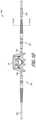
- FIG. 1 Fillustrates an exemplary side cross-sectional view inside a fiber mating sleeve connector in accordance with aspects of this disclosure.
- FIG. 1 Gillustrates another embodiment of a physiological measurement system in accordance with aspects of this disclosure.
- FIGS. 1 H- 1 Jillustrate enlarged views of portions of the physiological measurement system of FIG. 1 G in accordance with aspects of this disclosure.
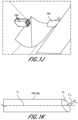
- FIG. 1 Killustrates an exemplary angled end of a fiber in accordance with aspects of this disclosure.
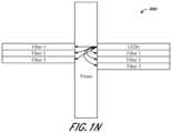
- FIGS. 1 L- 1 Nillustrate exemplary schematic diagrams of embodiments of physiological measurement systems in accordance with aspects of this disclosure.
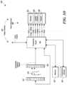
- FIG. 1 Oillustrates a block diagram depicting an embodiment of a computer hardware system configured to run software for implementing one or more embodiments of the physiological measurement system described herein.
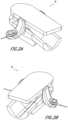
- FIG. 2 Aillustrates a perspective view of the noninvasive physiological sensor of FIGS. 1 B, 1 C, and 1 G .
- FIG. 2 Billustrates another perspective view of the noninvasive physiological sensor of FIG. 2 A .
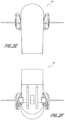
- FIG. 2 Cillustrates a back view of the noninvasive physiological sensor of FIG. 2 A .
- FIG. 2 Dillustrates a front view of the noninvasive physiological sensor of FIG. 2 A .
- FIG. 2 Eillustrates a top view of the noninvasive physiological sensor of FIG. 2 A .
- FIG. 2 Fillustrates a bottom view of the noninvasive physiological sensor of FIG. 2 A .
- FIG. 2 Gillustrates a side view of the noninvasive physiological sensor of FIG. 2 A .
- FIG. 2 Hillustrates another side view of the noninvasive physiological sensor of FIG. 2 A .
- FIG. 2 Iillustrates a top perspective view of a lower sensor body of the noninvasive physiological sensor of FIG. 2 A with a finger placed therewithin.
- FIG. 2 Jillustrates a bottom view of the noninvasive physiological sensor of FIG. 2 A in an open configuration with a finger positioned therewithin.
- FIG. 2 Killustrates a bottom view of the noninvasive physiological sensor of FIG. 2 A in a closed configuration where a finger positioned therewithin and tissue of the user is compressed by fibers in accordance with aspects of this disclosure.
- FIG. 2 Lillustrates another perspective view of the noninvasive physiological sensor of FIG. 2 A showing longitudinal and transverse axes of the device.
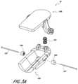
- FIG. 3 A- 3 Billustrate exploded views of the noninvasive physiological sensor of FIG. 2 A .
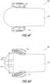
- FIG. 4 Aillustrates a perspective view of an upper sensor body of the noninvasive physiological sensor of FIG. 2 A .
- FIG. 4 Billustrates another perspective view of the upper sensor body of FIG. 4 A .
- FIG. 4 Cillustrates another perspective view of the upper sensor body of FIG. 4 A .
- FIG. 4 D- 4 Eillustrate side views of the upper sensor body of FIG. 4 A .
- FIG. 4 Fillustrates a top view of the upper sensor body of FIG. 4 A .
- FIG. 4 Gillustrates a bottom view of the upper sensor body of FIG. 4 A .
- FIG. 4 Hillustrates a front view of the upper sensor body of FIG. 4 A .
- FIG. 4 Iillustrates a back view of the upper sensor body of FIG. 4 A .
- FIG. 5 Aillustrates a top perspective view of a lower sensor body of the noninvasive physiological sensor FIG. 2 A .
- FIG. 5 Billustrates another top perspective view of the lower sensor body of FIG. 5 A .
- FIG. 5 Cillustrates a bottom perspective view of the lower sensor body of FIG. 5 A .
- FIG. 5 Dillustrates a top view of the lower sensor body of FIG. 5 A .
- FIG. 5 Eillustrates a bottom view of the lower sensor body of FIG. 5 A .
- FIG. 5 Fillustrates a side view of the lower sensor body of FIG. 5 A .
- FIG. 5 Gillustrates another side view of the lower sensor body of FIG. 5 A .
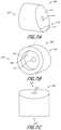
- FIG. 6 A- 6 Fillustrate various views of an embodiment of a fiber guide in accordance with aspects of this disclosure.
- FIGS. 7 A- 7 Fillustrate various views of another embodiment of a fiber guide in accordance with aspects of this disclosure.
- FIG. 1 Aillustrates a schematic diagram depicting a physiological measurement system 1 configured to generate a plethysmograph through a tissue 6 of a user that can be used alone or in combination with a noninvasive physiological measurement device, such as noninvasive physiological sensor 10 described herein.
- the physiological measurement system 1can include one or more emitters 2 and/or one or more detectors 8 .
- the one or more emitters 2can be light-emitting diodes (LED), for example.
- the one or more detectors 8can be photodetectors, photodiodes, phototransistors, and/or the like.
- each of the one or more emitters 2can be coupled to a fiber 3 (such as an optical fiber) to help collect, guide, and/or transmit the emitted light.
- a fiber 3such as an optical fiber
- fibers 3can be coupled together (for example, bundled together) by a coupler 5 and can join and/or meet an end of a fiber 5 a , which can contact (for example, probe) tissue 6 of a user as discussed in more detail below.
- the physiological measurement system 1can include an incident light (I) o detector 4 that can detect the light emitted by the one or more emitters 2 via fibers 3 before such light is transmitted to and/or through the tissue 6 .
- the light detected by the I 0 detector 4can act as a reference point by which light detected by the one or more detectors 8 can be compared. Such comparison can allow for a more refined analysis of physiological parameters determined based on light attenuated through the tissue 6 .
- I 0 detector 4is connected to a fiber 4 a which can connect and/or pass through coupler 5 (also referred to herein as “adapter”). Coupler 5 can join fibers 3 and fiber 4 a therewithin, and can allow an end of fiber 5 a to meet an end of the joined fibers 3 and 4 a . Fiber 5 a can receive the light transmitted via fibers 3 and can transmit such light to the tissue 6 , for example, when fiber 5 a contacts tissue 6 as discussed herein. Alternatively, in some embodiments, I 0 detector 4 is integrated into coupler 5 . In some embodiments, I 0 detector 4 is separate from coupler 5 . The tissue 6 can be any portion of a user's body.
- the tissue 6can be a portion of a user's finger, toe, nose, or other portion of the user's body.
- each of the one or more detectors 8can be coupled to fibers 7 (such as optical fibers) which can collect light after attenuation through tissue 6 .
- fibers 7such as optical fibers
- FIG. 1 Ashows the fibers 7 joined together proximate tissue 6
- the fibers 7can alternatively be spaced apart from each other when placed at the tissue 6 .
- each of the fibers 7 shown in FIG. 1 Acan be spaced apart and positioned adjacent tissue 6 . Such spacing of the fibers 7 can allow the fibers 7 to contact different portions of the tissue 6 (for example, finger) and/or probe different path length of the tissue 6 .
- Fibers 7can collect attenuated light after transmission through tissue 6 and guide the attenuated light to the one or more detectors 8 . While not shown in FIG. 1 , in some embodiments, system 1 includes a coupler similar to coupler 5 which is on the detector side of tissue 6 that couples end of fibers 7 with each other and/or to a separate fiber that probes tissue 6 , similar to fiber 5 a.
- the coupling of the one or more emitters 2 with fibers 3can advantageously allow light emitted from the one or more emitters 2 at a wide, divergent angle and/or direction to be guided, focused, and/or directed as a point source (for example, via an end of a fiber 3 ).
- Such couplingcan allow physical path length to be constant during transmission of light via the one or more fibers 3 , which can allow the emitters 2 to transmit light at and/or through highly absorbing mediums at a single or multiplicity of wavelengths and/or wavelength regions.
- Such wavelengthscan include any visible, near infrared (NIR), mid infrared (MIR) or any other spectroscopic band measurements, for example.
- system 1includes a plurality of emitters 2 (such as two, three, four, five, six, seven, or eight or more emitters 2 ) and each of the plurality of emitters 2 emit light at a different wavelength or wavelength region.
- the joining or meeting of the fibers 3 in the coupler 5 with fiber 5 acan allow for a smaller amount of contact area with tissue 6 since only fiber 5 a contacts the tissue 6 , which can reduce user discomfort.
- the coupling of the one or more emitters 2 with fibers 3can also provide reduction in light leakage.
- the use of fibers 3 and/or fiber 5 acan also allow a beam angle of the emitted light from the emitters 2 to be adjusted as desired.
- the integration of fiber 4 a within coupler 5can advantageously allow real time measurement of the amount of light emitted by the emitters 2 and/or transmitted by fibers 3 by the I 0 detector 4 in an efficient and convenient manner.
- the coupling of the one or more emitters 2 and/or the one or more detectors 8 with fibers 3 , fibers 7 , and/or fiber 5 acan allow the system to be configured such that fiber 5 a and one or more of the fibers 7 can face each other.
- fiber 5 a and one or more of the fibers 7can at least partially align along a longitudinal axis running through the fibers 5 , 7 and/or can be parallel to one another so that light can be transmitted through the tissue 6 and efficiently collected by fibers 7 .
- Such alignmentcan allow a greater portion of transmitted and attenuated light to be collected by the fibers 7 and passed to the one or more detectors 8 , thus increasing the accuracy of physiological measurements.
- the fiber(s) 3 , 5 a and fiber(s) 7can be pressed against tissue 6 so as to compress a portion of the tissue 6 and/or partially isolate the portion of tissue 6 to increase accuracy of physiological measurements.
- the compressed and/or isolated portion of tissue 6can be a portion of a user's finger that does not include bone. Transmitting and detecting attenuated light through such compressed and/or isolated portion of tissue 6 can allow physiological measurements to be taken without transmitting light through the user's bone, which can increase the accuracy of such measurements.
- fibers 5 acan probe (for example, press into) different portions of tissue 6 in order to increase the ability of the transmitted light to penetrate beyond the epidermis layer of skin to deeper regions of the tissue 6 where the blood vessels reside so as to obtain more accurate physiological measurements. For example, such probing with fibers 5 a can reduce the tendency for the transmitted light to remain in the epidermis layer without traveling through the blood vessels in the deeper regions of the tissue 6 .
- FIG. 1 Billustrates an embodiment of a physiological measurement system 9 that can be used alongside a noninvasive physiological sensor 10 .
- Physiological measurement system 9can include some or many of the features described with respect to physiological measurement system 1 .
- physiological measurement system 9includes an emitter assembly 20 which can include an emitter package 20 a , a fiber 20 b (which can be an optical fiber), and a coupler 20 c .
- Emitter package 20 acan include one or a plurality of emitters (such as two, three, four, five, six, seven, or eight or more emitters) which emit light at the same or different wavelengths or wavelength regions, similar to that discussed above.
- the emitter(s) within the emitter package 20 acan be light emitting diodes (LEDs), for example.
- each of the plurality of emitterscan be coupled to a fiber (similar to fiber 3 ) which can be bundled inside fiber 20 b .
- Coupler 20 ccan join the fiber 20 b to a single fiber (that can be similar or identical to fiber 5 a ) which can be held by a portion of sensor 10 and can contact a portion of tissue of a user.
- Coupler 20 ccan include a mating sleeve connector discussed in more detail below with reference to FIGS. 1 D and 1 F .
- physiological measurement system 9includes a detector assembly 30 , which can include a detector 30 a , a fiber 30 b (such as an optical fiber), and a coupler 30 c .
- Coupler 30 ccan be similar or identical to coupler 20 c .
- Coupler 30 ccan include a mating sleeve connector that positions fiber 30 b with respect to a single fiber similar to that described with reference to coupler 20 c above.
- FIG. 1 Cillustrates a physiological measurement system 500 which is the same as physiological measurement system 9 in many respects.
- system 500includes detector assembly 30 , detector 30 a , fiber 30 b , coupler 30 c , emitter package 20 a , fiber 20 b , coupler 20 c , and sensor 10 .
- system 500includes an I 0 detector 20 d (which can be the same in some or all respects as I 0 detector 4 discussed above), a fiber 20 e (such as an optical fiber) connected to I 0 detector 20 d , and an adapter 20 f .
- fiber 20 bcan house one or more fibers 20 b ′ coupled to one or more emitters within emitter package 20 a .
- Adapter 20 fcan join fiber 20 b with fiber 20 e into a fiber 23 (see FIGS. 1 D- 1 E ).
- FIG. 1 Eillustrates an exemplary cross-section through fiber 23 .
- the one or more fibers 20 b ′ connected to the one or more emitters of the emitter package 20 acan be positioned within fiber 23 adjacent, proximate, and/or surrounding fiber 20 e .
- coupler 20 ccan include a mating sleeve connector (such as an FC/APC mating sleeve commercially sold by Thorlabs, Inc.) that can join fiber 23 with a single fiber 20 g .
- 1 Fshows an exemplary schematic side cross-sectional view of an inside of such mating sleeve connector of coupler 20 c where an end of fiber 20 g is separated by an end of fiber 23 (and ends of fibers 20 b ′, 20 e ) by distance d 1 .
- Distance d 1can be 1 mm (0.040 inch), 2 mm (0.080 inch), 3 mm (0.12 inch), 4 mm (0.16 inch), 5 mm (0.20 inch), between 0 mm and 5 mm (0.20 inch), or any value or range bounded by any combination of these values or range, although the distance can be outside these values or range in some cases. While FIG.
- the number of fibers 20 b ′can be different than six.
- the number of fibers 20 b ′can be one, two, three, four, five, six, seven, or eight or more and can correspond to the amount of emitters in the emitter package 20 a .
- the detector assembly 30can include a coupler 30 c which can be similar or identical to coupler 20 c .
- Coupler 30 ccan join fiber 30 b with a fiber 30 d in a similar manner as that described with reference to fiber 23 and fiber 20 g above.
- FIG. 1 Gillustrates a physiological measurement system 500 ′ which is the same as physiological measurement system 500 in many respects.
- physiological measurement system 500 ′can include emitter package 20 a , fiber 20 b , I 0 detector 20 d , fiber 20 e , adapter 20 f , coupler 20 c , and/or fibers 23 and 20 g discussed above.
- Physiological measurement system 500 ′illustrates a detector assembly 30 ′ that includes multiple detectors 30 a coupled to fibers 30 b , and an adapter 30 e that can secure and/or orient portions of the fibers 30 b .
- FIG. 1 Gillustrates a physiological measurement system 500 ′ which is the same as physiological measurement system 500 in many respects.
- physiological measurement system 500 ′can include emitter package 20 a , fiber 20 b , I 0 detector 20 d , fiber 20 e , adapter 20 f , coupler 20 c , and/or fibers 23 and 20 g discussed above.
- FIG. 1 Hillustrates an enlarged perspective view of the adapter 30 e and the fibers 30 b entering adapter 30 e and also shows fibers 30 d exiting adapter 30 e .
- Ends of fibers 30 dcan be positioned proximate to, aligned with, and/or oriented relative to ends of fibers 30 b inside adapter 30 e .
- Adapter 30 ecan help position, align, and/or orient fibers 30 d so as to facilitate engagement and/or interaction with sensor 10 (for example, with fiber guides 300 , 300 ′ of sensor 10 which are discussed further below).
- the detectors 30 a and/or the I 0 detector 4can be connected to a cable or circuit, such as a flex circuit 33 .
- Flex circuit 33can transmit signals responsive to the light detected by detectors 30 a and/or the I 0 detector 4 to a user monitor or other processing device (such as user monitor 420 ) for further processing and/or analysis.
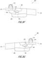
- FIGS. 1 I- 1 Jillustrate enlarged views of ends of fibers 30 d and fiber 20 g .
- ends of fibers 30 d and/or fiber 20 gcan be angled with respect to axes extending through the fibers 30 d , 20 g .
- ends of fibers 30 d and/or fiber 20 gcan be angled at an angle ⁇ such that the normal vector V N extending perpendicular to planes P 1 of the ends is angled with respect to axes A 1 that extend through a length (or a portion of the length) of fibers 30 d , 20 g .
- angle ⁇can be any angle or range between 0 and 90 degrees.
- angle ⁇can be 5 degrees, 10 degrees, 15 degrees, 20 degrees, 25 degrees, 30 degrees, 35 degrees, 40 degrees, 45 degrees, 50 degrees, 55 degrees, or 60 degrees, or any value or range therebetween, or any range bounded by any combination of these values, although values outside these values or ranges can be used in some cases.
- Such angles and/or orientation of ends of fibers 30 d and/or fiber 20 gcan advantageously allow the fibers 30 d , 20 g to press deeper into tissue which can in turn increase the ability for transmitted light to pass more directly through skin layers and blood vessels of the tissue (via fiber 20 g ) and be attenuated (to fibers 30 d ).
- the angles of ends of fibers 30 d , 20 gcan also advantageously better align with and/or conform to surfaces of tissue of a user (for example, skin surfaces on a bottom of a user's finger) which may be angled or curved.
- the angles of the ends of fibers 30 d , 20 gcan be relatively “flush” with such angled or curved tissue surfaces, which can aid the transmission of light into the tissue via fiber 20 g and can aid the collection of the attenuated light via fibers 30 d .
- FIGS. 1 I- 1 Jillustrate three fibers 30 d having ends having similar or identical angles, each of the ends of fibers 30 d can have different angles.
- an end of fiber 20 gis angled differently than one or more of the ends of the fibers 30 d .
- an end of fiber 20 gis angled the same as one or more of the ends of the fibers 30 d.
- FIG. 1 Lillustrates a simplified schematic diagram of a physiological measurement system 600 that operates in a transmissive manner—for example, where emitters and corresponding fibers transmit light into tissue and fibers on an opposite side of the tissue collect the attenuated light.
- FIGS. 1 M- 1 Nillustrates schematic diagrams of alternative configurations for physiological measurement systems.
- FIG. 1 Millustrates a simplified schematic diagram of a physiological measurement system 700 that operates in a reflective manner—for example, where emitters (and corresponding fibers) transmit light into tissue and fibers on the same side of the tissue collect the attenuated light.
- FIG. 1 Millustrates a simplified schematic diagram of a physiological measurement system 700 that operates in a reflective manner—for example, where emitters (and corresponding fibers) transmit light into tissue and fibers on the same side of the tissue collect the attenuated light.
- FIG. 1 Millustrates a simplified schematic diagram of a physiological measurement system 700 that operates in a reflective manner—for example, where emitters (and corresponding fibers) transmit light
- 1 Nillustrates a simplified schematic diagram of a physiological measurement system 800 that operates in both a transmissive and reflective manner—for example, where emitters (and corresponding fibers) transmit light into tissue and fibers on the same and the opposite side of the tissue collect the light attenuated through the tissue.
- physiological measurement systems 1 , 9 , 500 , 500 ′are illustrated as being configured to operate in a transmissive configuration, one of skill in the art will recognize that such systems 1 , 9 , 500 , 500 ′ can be modified to operate in the reflective configuration or a dual configuration (transmissive and reflective configuration), such as that shown in FIGS. 1 M- 1 N , without departing from the scope of the present disclosure.
- This disclosuredescribes embodiments of physiological measurement systems and noninvasive physiological measurement devices that can interact with a computing device and enable a user to measure, view, compare, analyze and/or download information relating to the respiratory system, for example, via the computing device, which may contain more advanced functionality than traditional systems and devices.
- the computing devicecan be, for instance, a cellphone or smartphone, tablet, laptop, personal digital assistant (PDA), and/or the like.
- the systems and devices described hereincan be used to generate information that can be incorporated into user interfaces that may be implemented in a user computing device.
- the user interfacescan depict displays that may be implemented in any of the user devices described herein.
- Such user interfaces shownmay be implemented in a mobile application such as an application that runs on a mobile operating system such as the AndroidTM operating system available from GoogleTM or the iOSTM operating system available from AppleTM.
- the user interfacescan be implemented in a web application that runs in a browser.
- user interfacesare merely examples that illustrate some example embodiments described herein and may be varied in other embodiments.
- user interface controls shownmay include buttons, touch-selective components and the like which may be altered to include any type of user interface control including, but not limited to, checkboxes, radio buttons, select boxes, dropdown boxes, textboxes or any combination of the same.
- the different user interface controlsmay be combined or their functionality may be spread apart amongst additional controls while retaining the similar or same functionality as shown and described herein.
- interfacesare shown having displays 424 , audible indicator 426 , and/or keypad 428 , other devices may implement similar user interfaces with other types of user input devices such as a mouse, keyboard, stylus, or the like.
- FIG. 1 Oillustrates a block diagram of an exemplary embodiment of a user monitoring system 400 that can be used alongside the physiological measurement systems 1 , 9 , 500 , 500 ′ and/or noninvasive physiological sensor 10 .
- the system 400can include a user monitor 402 including a processor 404 and a host instrument 408 .
- the system 400can include an emitter 416 , which can be the same as the one or more emitters 2 and/or emitter package 20 a , and a detector 420 , which can be the same as the one or more detectors 8 and/or detector 30 a .
- the processor 404can receive one or more intensity signal(s) indicative of one or more parameters of tissue of a user from the detector 420 .
- signals from the detector(s) 30 a and/or I 0 detector 4 , 20 dcan be transmitted to processor 404 via cables or circuits such as flex circuits 33 .
- the processor 404can also communicate with a host instrument 408 to display determined values calculated using the one or more intensity signals.
- the processor 404can comprise processing circuitry arranged on one or more printed circuit boards capable of installation into the monitor 402 , or capable of being distributed as some or all of one or more OEM components for a wide variety of host instruments monitoring a wide variety of user information.
- the processor 404can convert digital control signals into analog drive signals capable of driving emitters and can convert composite analog intensity signal(s) from light sensitive detectors into digital data.
- the processor 404can process signals from the detector 420 and transmit the processed signals to, for example, host instrument 408 , related to one or more intensity signals representative of the absorption or emission from transmissive or reflective sensor systems of a plurality of wavelengths of emitted light by body tissue.
- the system 400can include a plurality of emitters 416 irradiating the body tissue 418 with differing wavelengths of light, and one or more detectors 420 capable of detecting the light after attenuation by the tissue 418 , as discussed above.
- the system 400may include other electrical components such as, for example, a memory device 422 comprising an EPROM, EEPROM, ROM, RAM, microcontroller, combinations of the same, or the like.
- Other componentsmay include an optional temperature indicator 423 or other mechanisms for, for example, determining real-time emission wavelengths of the emitters 416 . These mechanisms can include, for example, the I 0 detector 4 , 20 d discussed above.
- the host instrument 408can receive signals indicative of the physiological parameter information calculated by the processor 404 .
- the host instrument 408preferably includes one or more display devices 424 capable of displaying indicia representative of the calculated physiological parameters of the tissue 418 at the measurement site.
- the host instrument 408can advantageously include a handheld housing capable of displaying one or more of a pulse rate, plethysmograph data, perfusion quality such as a perfusion quality index (“PITM”), signal or measurement quality (“SQ”), values of blood constituents in body tissue, including for example, SpO2, HbCO, HbMet, HbT, or the like.
- the host instrument 408can display values for one or more of HbT, Hb, blood glucose, bilirubin, or the like.
- the host instrument 408may be capable of storing or displaying historical or trending data related to one or more of the measured values, combinations of the measured values, plethysmograph data, or the like.
- the host instrument 408can also include an audio indicator 426 and user input device 428 , such as, for example, a keypad, touch screen, pointing device, voice recognition device, or the like.
- the host instrument 408can communicate with computing devices and/or physiological monitoring systems, such as physiological measurement system 1 , 9 , 500 , 500 ′ and/or noninvasive physiological sensor 10 , over wireless or wired public or private networks.
- such communicationcan be via wireless protocols such as Wi-Fi, Bluetooth, ZigBee, Z-wave, or radio frequency such as near field communication, or other wireless protocols such as cellular telephony infrared, satellite transmission, proprietary protocols, combinations of the same, and the like.
- wireless protocolssuch as Wi-Fi, Bluetooth, ZigBee, Z-wave, or radio frequency such as near field communication, or other wireless protocols such as cellular telephony infrared, satellite transmission, proprietary protocols, combinations of the same, and the like.
- FIGS. 2 A- 2 Hillustrate a noninvasive physiological sensor 10 that can be used alongside the physiological measurement systems 1 , 9 , 500 , 500 ′ and/or system 400 discussed above.
- FIGS. 3 A- 3 Billustrate exploded perspective views of the noninvasive physiological sensor 10 .
- Noninvasive physiological sensor 10can include an upper sensor body 100 and a lower sensor body 200 , as discussed further below. As also discussed further below, the upper sensor body 100 and the lower sensor body 200 can be coupled together via a joint, which can comprise upper sensor body hinges 114 and lower sensor body hinges 214 (see FIGS. 4 C and 5 B ).
- Noninvasive physiological sensor 10can include a biasing member 103 ( FIGS.
- the biasing member 103can include a spring, rubber material, and/or a compressible material, for example. Accordingly in a closed position (for example, as illustrated in FIG. 2 A ), a front portion 113 of the upper sensor body 100 (see FIG. 4 A ) can be spaced apart from a front portion 213 of the lower sensor body 200 (see FIG. 5 A ). In such configuration, the front portion 113 of the upper sensor body 100 can be approximately parallel to the front portion 213 of the lower sensor body 200 .
- Noninvasive physiological sensor 10can include one or more probe guides configured to retain and/or secure (or at least partially retain and/or at least partially secure) one or more probes.
- the one or more probe guidescan be fiber guides 300 , 300 ′ discussed further below, such as two fiber guides, which can help secure a portion of one or more probes coupled to one or more emitters and/or one or more detectors.
- the one or more probescan be used to compress tissue of the user.
- the one or more probescan have ends which contact and/or compress the tissue of the user.
- the one or more probescan couple to the one or more emitters and/or one or more detectors and can help at least partially guide light from the one or more emitters to the tissue and/or can help at least partially guide attenuated light after transmission through the tissue of the user.
- the one or more probescan comprise, for example, fibers, such as optical fibers.
- the one or more probescan comprise fibers 105 and/or 107 (see FIGS. 3 A- 3 B ) which can be the same in many or all respects to fibers 5 a , 20 g , and/or 30 d .
- fiber guides 300 , 300 ′can fit in recesses on sides of the lower sensor body 200 .
- the fiber guides 300 , 300 ′can have through-holes 314 , 314 ′ configured to permit the fibers 105 , 107 to pass therethrough, and the fiber guides 300 , 300 ′ can fit in the recesses on the sides of the lower sensor body 200 so that the through-holes 314 , 314 ′ of the fiber guides 300 , 300 ′ align with one or more holes 230 in the lower sensor body 200 (see FIGS. 6 B, 7 B, and 5 F ).
- the fiber guides 300 , 300 ′can at least partially secure the fibers 105 , 107 (for example, via the through-holes 314 , 314 ′) and/or align the fibers 105 , 107 so that they can pass through the one or more holes 230 of the lower sensor body 200 . While the figures illustrate recessed portions on the sides of the lower sensor body 200 that are sized and/or shaped to receive a portion of the fiber guides 300 , 300 ′ (for example, recessed portions 250 as shown in FIGS. 5 A and 5 B ), the upper sensor body 100 can additionally and/or alternatively include recessed portions on sides thereof which are configured to receive at least a portion of fiber guides 300 , 300 ′.
- Noninvasive physiological sensor 10can be secured to a finger 11 of a user.
- FIG. 2 Iillustrates noninvasive physiological sensor 10 with the upper sensor body 100 removed so as to better show the finger 11 when positioned within the noninvasive physiological sensor 10 .
- the noninvasive physiological sensor 10(or a portion thereof) can be shaped to conform to the shape of a portion of a user's body.
- the lower sensor body 200(or a portion thereof) can be shaped to conform to a finger 11 of the user.
- the lower sensor body 200 (or a portion thereof)can be shaped to conform to a skin-side surface of finger 11 of the user.
- FIG. 2 J- 2 Killustrate a bottom view of the noninvasive physiological sensor 10 where a finger 11 is shown in phantom lines.
- FIG. 2 Jillustrates the noninvasive physiological sensor 10 in an open position
- FIG. 2 Killustrates the noninvasive physiological sensor 10 in a closed position.
- the noninvasive physiological sensor 10can be configured to move the fibers 105 , 107 towards each other within an interior space defined by the noninvasive physiological sensor 10 so that a portion of the user's finger 11 is compressed. As discussed further herein, such compression allows light to be transmitted through and attenuated by a portion of the user's tissue and detected without having to pass through a user's bone.
- such compressionalso allows the fibers 105 , 107 to more directly transmit light through, and collect attenuated light from, deeper region so the tissue which include the user's blood vessels. This can advantageously increase the accuracy of physiological measurements which rely on transmitting light through such blood vessels.
- FIGS. 4 A- 4 Iillustrates various views of the upper sensor body 100 of the noninvasive physiological sensor 10 .
- Upper sensor body 100can include a top surface 110 (see FIGS. 4 A- 4 B ) and a bottom surface 111 opposite to the top surface 110 (see FIG. 4 C ).
- Upper sensor body 100can also include a front portion 113 and a back portion 115 (see FIG. 4 A ).
- the front portion 113can be shaped to correspond to the shape of a front portion of the lower sensor body 200 (such as front portion 213 ).
- the front portion 113can be curved and/or rounded, as shown in FIG. 4 A .
- the noninvasive physiological sensor 10can include a joint configured to rotatably couple the upper sensor body 100 to the lower sensor body 200 and allow the upper sensor body 100 and/or the lower sensor body 200 to rotate with respect to each other.
- the jointcan allow the upper sensor body 100 and/or the lower sensor body 200 to rotate about a transverse axis 52 of the noninvasive physiological sensor 10 , which can be perpendicular to a longitudinal axis 50 that extends through a length of the noninvasive physiological sensor 10 .
- the jointcan include a first coupling portion that extends from the upper sensor body 100 and a second coupling portion that extends from the lower sensor body 200 , whereby the first and second coupling portions couple to each other and allow the upper and lower sensor bodies 100 , 200 to be rotatably coupled to one another.
- the first coupling portioncan include one or more hinges 114 (see FIGS. 4 A- 4 E ), such as one, two, three, or four or more hinges 114 .
- the first coupling portioncan include two hinges 114 that extend from bottom surface 111 of the upper sensor body 100 .
- the hinges 114can extend from the bottom surface 111 in a direction generally perpendicular to the bottom surface 111 . As discussed and shown herein, the hinges 114 can extend from the bottom surface 111 of the upper sensor body 100 towards the lower sensor body 200 when the noninvasive physiological sensor 10 is assembled.
- the first coupling portion of the upper sensor body 100can be sized and/or shaped to fit within a recessed portion of the lower sensor body 200 so as to facilitate rotation of the upper sensor body 100 with respect to the lower sensor body 200 .
- extending or “free” ends of the hinges 114can be curved and/or rounded so as to fit at least partially within a curved recessed portion 220 on the lower sensor body 200 (see FIGS. 4 C and 5 A- 5 B ).
- the corresponding shape of the hinges 114 and the recessed portions 220can facilitate smooth rotation of the upper sensor body 100 with respect to the lower sensor body 200 with little or no interference from the hinges 114 .
- upper sensor body 100can include a recessed portion 120 that is sized and/or shaped to correspond to the size and/or shape of the second coupling portion extending from the lower sensor body 200 so as to facilitate rotation of the lower sensor body 200 with respect to the upper sensor body 100 .
- the bottom surface 111 of the upper sensor body 100can have a curved recessed portion 120 that corresponds to a curved and/or rounded shape of hinges 214 of the second coupling portion of the lower sensor body 200 .
- the corresponding shape of the hinges 214 and the recessed portions 120can facilitate smooth rotation of the lower sensor body 200 with respect to the upper sensor body 100 with little or no interference from the hinges 214 .
- the recessed portions 120 , 220can thus facilitate smooth rotation of hinges 114 , 214 and also allow the device 10 to be compact in size.
- the device 10can have less vertical height than would otherwise be needed to accommodate spacing and/or rotation of the hinges 114 , 214 proximate to the upper and lower sensor bodies 100 , 200 .
- the one or more hinges 114 , 214can include one or more holes 118 , 218 extending therethrough sized and/or shaped to allow a pin (not shown) to pass therethrough.
- the pincan extend through holes 118 of the hinges 114 and also extend through holes 218 on hinges 214 so as to secure and/or couple the hinges 114 to the hinges 214 .
- hinges 114can be adjacent to hinges 214 and can be positioned in between hinges 214 (compare, for example, FIG. 4 G and FIG. 5 D ).
- hinges 214can be adjacent to hinges 114 and can lay in between hinges 114 .
- upper sensor body 100has one hinge 114 .
- upper sensor body 100has two or more hinges 114 .
- lower sensor body 200has one hinge 214 .
- lower sensor body 200has two or more hinges 214 .
- the noninvasive physiological sensor 10can include a biasing member 103 .
- Biasing member 103can include a compression spring, among other materials described herein. Where the biasing member 103 comprises a compression spring, the spring can comprise various strength and/or stiffness properties, and/or other material properties.
- Biasing member 103can be in contact with or be coupled to the upper sensor body 100 and/or the lower sensor body 200 .
- the upper sensor body 100can include a protrusion and/or recess for receiving one end of the biasing member 103 .
- upper sensor body 100can include a recess 122 on bottom surface 111 that is sized and/or shaped to receive an end of the biasing member 103 .
- Recess 122can be, for example, a cylindrical recess (see FIG. 4 C ).
- the upper sensor body 100can additionally or alternatively include a skirt wall extending around a perimeter of a portion of the bottom surface 111 of the upper sensor body 100 which can help secure and/or align the biasing member 103 or a portion thereof.
- Biasing member 103can be adhered to the bottom surface 111 of the upper sensor body 100 .
- Biasing member 103can space the upper sensor body 100 from the lower sensor body 200 .
- the lower sensor body 200can include a protrusion (not shown) and/or recess for receiving one end of the biasing member 103 . For example, as shown in at least FIGS.
- lower sensor body 200can include a recess 222 on top surface 211 of the lower sensor body 200 that is sized and/or shaped to receive an end of the biasing member 103 .
- Recess 222can be, for example, a cylindrical recess 222 (see FIGS. 5 A- 5 B ).
- the lower sensor body 200can additionally or alternatively include a skirt wall extending around a perimeter of a portion of the top surface 211 of the lower sensor body 200 which can help secure and/or align the biasing member 103 .
- Biasing member 103can be adhered to the top surface 211 of the lower sensor body 200 .
- Biasing member 103can be adhered to the top surface 211 of the lower sensor body 200 and the bottom surface 111 of the upper sensor body 100 .
- Biasing member 103can be positioned at an approximate center of a width of the noninvasive physiological sensor 10 along transverse axis 52 (see FIG. 2 L ). Such positioning can advantageously allow the upper sensor body 100 and/or the lower sensor body 200 to be properly balanced and/or positioned when rotated relative to one another and can also ensure that there is a symmetric restoring force to appropriately bias the noninvasive physiological sensor 10 .
- FIGS. 2 G- 2 Hillustrate side views of the noninvasive physiological sensor 10 including biasing member 103 at a front portion 60 of the noninvasive physiological sensor 10 .
- the front portion 60 of the noninvasive physiological sensor 10can rotate about the pin extending through each of the first and second coupling portions of the upper and lower sensor bodies 100 , 200 discussed above.
- biasing member 103can be not compressed or not expanded and/or can be minimally compressed and/or minimally expanded. As shown in FIGS. 2 G- 2 H, 4 A , and 5 A, in a closed position, a back portion 115 of the upper sensor body 100 can be spaced apart from a back portion 215 of the lower sensor body 200 .
- biasing member 103can allow the upper sensor body 100 to rotate about the pin relative to the lower sensor body 200 and/or the lower sensor body 200 to rotate about the pin relative to the upper sensor body 100 .
- the biasing member 103can bias the upper sensor body 100 and/or the lower sensor body 200 in a position, in which no and/or minimal external forces are applied.
- the biasing member 103can also help close and/or secure the sensor 10 to a user's finger, for example.
- the biasing member 103can allow the noninvasive physiological sensor 10 to comfortably be secured to a user, such as on a finger of a user.
- Biasing member 103can be coupled near the front portion 113 , 213 of the upper sensor body 100 and the lower sensor body 200 .
- biasing member 103can be fit within recesses 122 , 222 of the upper and lower sensor bodies 100 , 200 near a perimeter edge of the front portions 113 , 213 .
- the biasing member 103can space the upper sensor body 100 from the lower sensor body 200 . As shown in at least FIG. 2 L , for example, this can allow a greater range of rotation about the joint.
- Such configurationscan allow for the noninvasive physiological sensor 10 to accommodate a greater variety of shapes and sizes of, for example, fingers of users.
- noninvasive physiological sensor 10can include fiber guides 300 , 300 ′ that secure and/or align fibers 105 , 107 and that can fit within recessed portions 250 (see FIGS. 5 A- 5 B ) along sides of lower sensor body 200 .
- the fibers 105 , 107can be configured to pass through through-holes 314 , 314 ′ in fiber guides 300 , 300 ′ and pass through holes 230 in the lower sensor body 200 into an interior space defined by the lower sensor body 200 .
- the interior space defined by the lower sensor body 200can be, for example, a volume defined by the lower sensor body 200 that is sized and/or shaped to conform to a portion of a finger of a user.
- the fiber guides 300 , 300 ′can be configured such that they move and/or compress when engaged by a swivel mechanism of the noninvasive physiological sensor 10 .
- the swivel mechanismcan include arms 112 that extend from upper sensor body 100 (see FIGS. 4 A- 4 B ) that are configured to engage fiber guides 300 , 300 ′.
- Arms 112can include a top end connected to and extending from sides of the upper sensor body 100 and a bottom end opposite to the top end.
- the swivel mechanismcan comprise first and second arms 112 that extend from sides of the upper sensor body 100 .
- Arms 112can include slots 116 extending along a portion of a length of the arms 112 .
- the lower sensor body 200can include recessed portions 240 on sides of the lower sensor body 200 that are sized, shaped, and/or inclined to correspond with a portion of the arms 112 of the swivel mechanism and/or are sized, shaped, and/or inclined so as to facilitate movement of the arms 112 along the sides of the lower sensor body 200 when the upper and lower sensor bodies 100 , 200 are rotated with respect to each other.
- recessed portions 240 on sides of the lower sensor body 200that are sized, shaped, and/or inclined to correspond with a portion of the arms 112 of the swivel mechanism and/or are sized, shaped, and/or inclined so as to facilitate movement of the arms 112 along the sides of the lower sensor body 200 when the upper and lower sensor bodies 100 , 200 are rotated with respect to each other.
- the recessed portions 240can be recessed from sides of the lower sensor body 200 and inclined inwardly toward an interior portion of the lower sensor body 200 so as to conform to a shape of the arms 112 of the swivel mechanism.
- arms 112 of the swivel mechanism of noninvasive physiological sensor 10can extend from sides of the upper sensor body 100 and flare outward in a direction parallel to transverse axis 52 (see FIGS. 4 H- 4 I ).
- arms 112rotate and/or swivel between different positions.
- interior sides of arms 112(which face an interior of the noninvasive physiological sensor 10 when assembled) can be angled outwards from middle portions 57 of the arms 112 to end portions 59 of the arms 112 .
- interior surfaces of arms 112can be inclined outward from a region between the middle portions 57 to the end portions 59 .
- fiber guides 300can secure fibers 105 , 107 on sides of the lower sensor body 200 and fit at least partially within recesses 250 . Further, when noninvasive physiological sensor 10 is assembled, arms 112 can sit at least partially within recessed portions 240 , adjacent to and on an outside of fiber guides 300 , such that arms 112 contact sides of fiber guides 300 . Slots 116 on arms 112 allow fibers 105 , 107 to pass therethrough and couple to emitters and/or detectors as discussed with reference to the systems 1 , 9 , 500 , and 500 ′ above. When the noninvasive physiological sensor 10 is in a closed position (as shown by FIGS.
- FIG. 2 Kin this closed position, the fibers 105 , 107 which are secured and/or coupled with the fiber guides 300 , are forced inward toward each other within the interior space defined by the lower sensor body 200 . As illustrated by FIG. 2 K , when forced inward toward each other in this closed position, the fibers 105 , 107 can compress a portion of a tissue of a finger 11 of a user. This compressed portion of tissue is illustrated by dotted lines 13 in FIG. 2 K .
- Utilizing one or more probes such as fibers 105 , 107 (for example, ends of fibers 105 , 107 ) to emit light through, and detect attenuated light from, tissue of a usercan advantageously allow a short path length of tissue to be interrogated.
- the compression of tissue in such mannercan allow the fibers 105 , 107 to transmit light through, and collect attenuated light from, deeper regions of tissue where blood vessels are present, which can advantageously increase the accuracy and ability of determining physiological measurements.
- the one or more probescan be moved toward one another such that, when they compress the tissue of the user, a distance between the ends of the fibers 105 , 107 are between 1/12 inch (0.21 cm) and 1 ⁇ 4 inch (0.64 cm).
- the distance between the ends of the fibers 105 , 107 when compressing a portion of the tissue of the usercan be less than or equal to 1/12 inch (0.21 cm), 1/11 inch (0.23 cm), 1/10 inch ( 0 .
- the one or more probescan be moved toward one another such that, when they compress the tissue of the user, the compressed tissue has a thickness 1/12 inch (0.21 cm) and 1 ⁇ 4 inch (0.64 cm), for example.
- the one or more probescan be moved toward one another such that, when they compress the tissue of the user, the compressed tissue has a thickness less than or equal to 1/12 inch (0.21 cm), 1/11 inch (0.23 cm), 1/10 inch (0.25 cm), 1/9 inch (0.28 cm), 1 ⁇ 8 inch (0.32 cm), 1/7 inch (0.36 cm), 1 ⁇ 6 inch (0.42 cm), 1 ⁇ 5 inch (0.51 cm), 1 ⁇ 4 of inch (0.64 cm), or any value therebetween, or any range bounded by any combination of these values, although values outside these are possible. Interrogating a short path length of tissue allows measurements to be taken through highly absorbing media which enables detection of signals that may normally fall below detectable limits.
- fibers 105 , 107can be used to transmit, and receive, light through a portion of tissue of a user without directing or allowing the light or optical radiation to pass through a bone, cartilage, or muscle, and/or without directing light or optical radiation toward a bone, cartilage, or muscle of a user.
- fiber(s) 30 d and fiber 20 gcan be moved towards one another via interaction with noninvasive physiological sensor 10 similarly as discussed with reference to fibers 105 and 107 above.
- arms 112can slide within, along, and/or adjacent to recessed portions 240 of lower sensor body 200 . More specifically, a region between middle portions 57 and end portions 59 of arms 112 can slide within, along, and/or adjacent to recessed portions 240 . In a closed position, regions proximate to (for example, below) the middle portions 57 are in contact with recessed portions 240 . When the upper and lower sensor bodies 100 , 200 are rotated about each other, the recessed portions 240 contact a region between the middle portions 57 and end portions 59 of arms 112 .
- end portions 59 of arms 112can contact the recessed portions 240 and fiber guides 300 .
- the end portions 59can contact the recessed portions 240 at an end of the slots 116 since fibers 105 , 107 pass through the slots 116 and through-holes 314 in fiber guides 300 .
- the outward inclination of the interior surfaces of arms 112(see FIGS. 4 H- 4 I ) from middle portions 57 to end portions 59 allows less force to be applied by the arms 112 to the fiber guides 300 .
- Slots 116can have a length corresponding to a desired rotational capacity of the upper sensor body 100 and lower body sensor 200 with respect to one another. For example, where it is desirable to allow the upper and lower sensor bodies 100 , 200 to rotate about each other to a large degree, slots 116 can have a length that is a greater percentage of a length of the arms 112 .
- the slots 116can have a length that is a percentage of a length of the arms 112 .
- the length of the slots 116can be 20%, 30%, 40%, 50%, 60%, 70%, 80%, or 90% of the length of the side rails 110 , or any value or range therebetween, although values outside these ranges can be used in some cases.
- arms 112can extend from sides of upper sensor body 100 and curve towards front portion 60 of noninvasive physiological sensor 10 and front portion 113 of the upper sensor body 100 .
- the curvature of the arms 122 in this directioncan advantageously allow a portion of the interior surface of the arms 112 to maintain contact with the fiber guides 300 when the noninvasive physiological sensor 10 is rotated.
- the interior surfaces of the arms 112can maintain contact with the fiber guides 300 between the middle portions 57 and the end portions 59 of the arms 112 .
- the arms 112are curved toward the front portion 60 of the noninvasive physiological sensor 10 so as to correspond with the rotational movement of the upper and lower sensor bodies 100 , 200 with respect to one another. Further, maintaining contact between the arms 112 and the fiber guides 300 advantageously allows the fiber guides 300 and coupled fibers 105 , 107 to maintain alignment and positioning, while also allowing precise adjustment and movement of the fibers 105 , 107 toward and away from each other within the interior space defined by the lower sensor body 200 .
- noninvasive physiological sensor 10can include one or more stoppers 130 configured to prevent the upper sensor body 100 from rotating beyond a limit with respect to the lower sensor body 200 .
- noninvasive physiological sensor 10can include two stoppers 130 , each extending inwardly from interior surfaces of the arms 112 . Stoppers 130 can be positioned along the interior surface of the arms 112 such that they are in contact with a top surface 211 of the lower sensor body 200 when the noninvasive physiological sensor 10 is in a closed position. For example, as shown in FIGS. 4 H- 4 I and 2 C- 2 D , when the noninvasive physiological sensor 10 is in the closed position, stoppers 130 sit against a top surface 211 of lower sensor body 200 .
- stoppers 130prevent the upper sensor body 100 from rotating beyond a maximum limit relative to the lower sensor body 200 .
- Thisadvantageously prevents the noninvasive physiological sensor 10 from applying to much force or pressure to a user's tissue (for example, a finger 11 ) when the tissue is placed therewithin, especially where the noninvasive physiological sensor 10 includes a biasing member 103 which may tend to over-rotate the upper sensor body 100 relative to the lower sensor body 200 in some cases.
- FIGS. 5 A- 5 Gillustrates various views of lower sensor body 200 .
- Lower sensor body 200can include a top surface 211 which faces bottom surface 111 of the upper sensor body 100 when noninvasive physiological sensor 10 is assembled and a bottom surface opposite 237 to the top surface 211 of the lower sensor body 200 .
- the top surface 211 of the lower sensor body 200can include a recessed portion 210 .
- noninvasive physiological sensor 10 or a portion thereofcan be shaped to conform to a portion of a user, such as a finger 11 of a user.
- the recessed portion 210 of the top surface 211can be shaped to conform to a user's finger.
- top surface 211can be substantially flat and can extend along sides of the lower sensor body 200 and the recessed portion 210 can be curved and/or inclined from interior edges of the substantially flat portion of the top surface 211 .
- the top surface 211can be flat or substantially flat except for recess 222 (discussed above), recessed portion 220 (discussed above), and/or recessed portion 210 .
- recessed portion 210can be curved and/or inclined along sides thereof, and the sides of the recessed portion 210 can be sized and/or shaped to conform to sides of a user's finger.
- the recessed portion 210can have a front section that is sized and/or shaped to conform to a tip or front portion of a user's finger.
- the front of the recessed portion 210can be curved and/or inclined to conform to a tip of a user's finger, and can resemble a portion of a bowl.
- the lower sensor body 200can have one or more holes 230 configured to allow fibers 105 , 107 to pass therethough into an interior space defined by the lower sensor body 200 .
- the interior space defined by the lower sensor body 200can be the space or volume defined by the recessed portion 210 .
- lower sensor body 200can have an opening 270 .
- noninvasive physiological sensor 10when in a closed position, can compress a portion of tissue of a user, for example, by movement of the fibers 105 , 107 toward each other via the interaction of the swivel mechanism and the fiber guides 300 .
- Opening 270can advantageously permit inspection of the compressed or pinched portion of tissue of the user from underneath. Such inspection can involve, for example, checking to make sure adequate skin tissue has been isolated so that an accurate physiological measurement can take place. Such inspection can also allow a caregiver or a user to ensure that the fibers 105 , 107 are aligned and/or extending properly, and/or whether or not a user's tissue is present in the device. Opening 270 can be rectangular, or alternatively, square, circular, among other shapes.
- lower sensor body 200can include legs 260 that extend outward from and along a portion of bottom surface 237 of lower sensor body 200 .
- Legs 260can allow the lower sensor body 200 and/or the noninvasive physiological sensor 10 to rest atop a surface (such as a flat surface). Where a portion of the bottom surface 237 of lower sensor body 200 is curved (see, for example, FIG. 5 C ), legs 260 can provide support that allows the sensor 10 to sit on a surface without rocking along longitudinal axis 50 of the sensor 10 .
- the noninvasive physiological sensor 10can have a joint including a first coupling portion and a second coupling portion.
- the first coupling portioncan be one or more hinges 114 positioned on the upper sensor body 100 and the second coupling portion can be one or more hinges 214 positioned on the lower sensor body 200 .
- Hinges 214can be positioned adjacent to and on the outside of the hinges 114 and can be shaped to correspond with recessed portion 120 on the bottom surface 111 of upper sensor body 100 , as discussed above.
- Recess 222can be sized to fit an end of biasing member 103 therewithin, as also discussed above.
- Recessed portion 220can be shaped to correspond with the shape of hinges 114 so as to facilitate rotation of the hinges 113 with little or no interference with the lower sensor body 200 , as discussed above.
- FIGS. 5 F- 5 Gillustrate side views of the lower sensor body 200 .
- These figuresshow an exemplary shape of recessed portions 240 , 250 .
- recessed portions 240can be shaped to accommodate a portion of the arms 112 of the swivel mechanism of the noninvasive physiological sensor 10 .
- the recessed portions 240can be sized, shaped, and/or oriented to facilitate movement of the arms 112 of the swivel mechanism.
- the recessed portions 240can have a width (in a direction parallel to longitudinal axis 50 ) that is larger than or equal to a width of the arms 112 of the swivel mechanism so as to allow the arms 112 to at least partially fit therewithin.
- the recessed portions 240can be oriented so as to conform to the curvature of the arms 112 .
- the recessed portions 240can be curved toward a front 213 of the lower sensor body 200 similar to the direction of curvature of the arms 112 of the swivel mechanism.
- recessed portions 240can be sized, shaped, and/or oriented so as to facilitate movement of the arms 112 or the swivel mechanism there within and adjacent to sides of the lower sensor body 200 , which can, among other things allow the arms 112 to contact the fiber guides 300 as discussed above.
- FIGS. 5 F- 5 Galso illustrate recesses 250 .
- the recesses 250can be sized and/or shaped to allow a portion of the fiber guides 300 to fit at least partially there within.
- the recesses 250can be sized and/or shaped to allow an end of the fiber guides 300 to fit at least partially within adjacent to sides of the lower sensor body 200 .
- FIGS. 5 A- 5 Gillustrate the lower sensor body 200 having one hole 230 on each of the sides of the lower sensor body 200
- the lower sensor body 200can have a different number of holes 230 on one or both of the sides of the lower sensor body 200 .
- lower sensor body 200can have a plurality of holes 230 (such as three holes 230 ) on a first side of lower sensor body 200 , where each of the plurality of holes 230 are sized and/or shaped to receive fibers 30 d .
- the hole 230appearing on the right side of lower sensor body 200 as shown in FIG.
- lower sensor body 200can have a plurality of holes 230 on such right side of lower sensor body 200 that are sized and/or shaped to receive one or more probes which are coupled to emitters.
- lower sensor body 200can include one or more holes 230 on one of both sides of lower sensor body 200 which allow one or more fibers to move through and/or within the lower sensor body 200 to contact (for example, probe) tissue of a user.
- FIGS. 6 A- 6 Fillustrate various views of an embodiment of a fiber guide 300 (also referred to herein as “probe guide” and “spacer”).
- Fiber guide 300has an interior end 320 configured to contact the recess 250 of the lower sensor body 200 when the noninvasive physiological sensor 10 is assembled and an exterior end 310 configured to contact an interior surface of the arms 112 of the swivel mechanism when the sensor 10 is assembled.
- fiber guide 300can have a through-hole 314 sized and/or shaped to permit fiber 105 , 107 (or any of the other fibers discussed herein) to pass therethrough. Through-hole 314 can begin at exterior end 310 and end at interior end 320 .
- Interior end 320can have an outer portion 330 separated from an inner portion 313 by an intermediate portion 340 .
- the inner portion 313can surround the through-hole 314 .
- the intermediate portion 340can be recessed from a plane at the interior end 320 .
- the intermediate portion 340can be in between the outer portion 330 and the inner portion 313 , and can be open, as shown in FIG. 6 B .
- Any of outer portion 330 , inner portion 313 , and/or intermediate portion 340can be annular in shape, for example.
- end 310 of the fiber guide 300can include an inclined portion 312 .
- the entire end 310comprises an inclined portion 312 .
- only a portion of the end 310comprises an inclined portion 312 .
- end 310also includes a non-inclined portion 317 .
- the fiber guide 300can have a circular or partially circular cross-section.
- a cross-section of fiber guide 300 near the interior end 320can be circular, whereas a cross-section near the exterior end 310 can be partially circular due to the inclination of the exterior end 310 .
- the inclination of exterior end 310 of the fiber guide 300can correspond to the inclination and/or orientation of the arms 112 .
- interior surfaces of arms 112can be inclined outward from a region between the middle portions 57 to end portions 59 .
- Such inclinationallows more and/or less force to be applied by the arms 112 to the fiber guides 300 when the swivel mechanism is engaged via rotation of the upper sensor body 100 about the lower sensor body 200 (or vice versa).
- the inclination of exterior end 310 of fiber guide 300allows the inclined interior surface of the arms 112 to gradually slide along and/or contact the exterior end 310 so that the contact and/or force applied to the fiber guide 300 is more precise.
- end 310can have a non-inclined portion 317 in some embodiments.
- the non-inclined portion 317can help facilitate less contact with the interior surface of arms 112 in combination with the inclined portion 312 so as to vary the contact and/or force applied to the fiber guide 300 via the arms 112 .
- fiber guide 300can include more than one hole 314 , such as two, three, four, five, six, or seven holes extending through fiber guide 300 .
- Each of the holes 314can be sized and shaped to receive a fiber, such as any of the fibers discussed previously.
- fiber guide 300can include three holes 314 which can be sized and/or shaped to receive one of the three fibers 30 d that are shown and discussed with reference to FIGS. 1 G- 1 J .
- Such plurality of holes 314can be positioned through the fiber guide 300 in various locations, for example, along a single vertical plane to match the layout of the fibers 30 d as shown in FIG. 1 J , or in other locations and/or positions.
- FIGS. 7 A- 7 Fillustrate various views of another embodiment of a fiber guide 300 ′ (also referred to herein as “probe guide” and “spacer”). While much of the previous discussion with respect to the noninvasive physiological sensor 10 and FIGS. 2 A- 5 G was made with reference to fiber guide 300 , fiber guide 300 ′ can be incorporated into noninvasive physiological sensor 10 alongside or in place of fiber guide 300 and any of the other components of noninvasive physiological sensor 10 described previously.
- Fiber guide 300 ′has an interior end 320 ′ configured to contact the recess 250 of the lower sensor body 200 when the noninvasive physiological sensor 10 is assembled and an exterior end 310 ′ configured to contact an interior surface of the arms 112 of the swivel mechanism when the sensor 10 is assembled.
- fiber guide 300 ′can have a through-hole 314 ′ sized and/or shaped to permit fiber 105 , 107 (or any of the other fibers discussed herein) to pass therethrough.
- Through-hole 314 ′can begin at exterior end 310 ′ and can extend through a portion of fiber guide 300 ′.
- Interior end 320 ′can have an outer portion 330 ′ and an open cavity 340 ′ defined within the outer portion 330 ′.
- the cavity 340 ′can have a surface that is parallel to a plane of the end 320 ′, and through-hole 314 ′ can extend from end 310 ′ through an interior of the fiber guide 300 ′ to the surface of cavity 340 ′.
- end 310 ′ of the fiber guide 300 ′can include an inclined portion 312 ′.
- only a portion of the end 310 ′comprises an inclined portion 312 ′, as illustrated in at least FIGS. 7 A and 7 E- 7 F .
- end 310 ′also includes a non-inclined portion 317 ′.
- FIGS. 7 E- 7 Fshow side views of fiber guide 300 ′ and show the inclined portion 312 ′ and the non-inclined portion 317 ′ of the end 310 ′.
- the fiber guide 300 ′can have a circular or partially circular cross-section.
- a cross-section of fiber guide 300 ′ near the interior end 320 ′can be circular, whereas a cross-section near the exterior end 310 ′ can be partially circular due to the inclination of the exterior end 310 ′.
- the inclination of exterior end 310 ′ of the fiber guide 300 ′can correspond to the inclination and/or orientation of the arms 112 .
- interior surfaces of arms 112can be inclined outward from a region between the middle portions 57 to end portions 59 .
- Such inclinationallows more and/or less force to be applied by the arms 112 to the fiber guides 300 ′ when the swivel mechanism is engaged via rotation of the upper sensor body 100 about the lower sensor body 200 (or vice versa).
- the inclination of exterior end 310 ′ of fiber guide 300 ′allows the inclined interior surface of the arms 112 to gradually slide along and/or contact the exterior end 310 ′ so that the contact and/or force applied to the fiber guide 300 ′ is more precise.
- Such precision in contact and/or forceallows the fibers 105 , 107 (or any of the other fibers discussed herein) positioning and/or movement to be more controlled, so that tissue of a user (for example, tissue of a user's finger) can be compressed in a controlled manner.
- Controlling the compression of the user's tissue within the noninvasive physiological sensor 10can ensure that the fibers 105 , 107 (or any of the other fibers discussed herein) are within a desired alignment so that more accurate physiological measurements can be taken and also reduces discomfort to the user resulting from such compression.
- end 310 ′can have a non-inclined portion 317 ′ in some embodiments.
- the non-inclined portion 317 ′can help facilitate less contact with the interior surface of arms 112 in combination with the inclined portion 312 ′ so as to vary the contact and/or force applied to the fiber guide 300 ′ via the arms 112 .
- fiber guide 300 ′can include more than one hole 314 ′, such as two, three, four, five, six, or seven holes extending through fiber guide 300 ′.
- Each of the holes 314 ′can be sized and shaped to receive a fiber, such as any of the fibers discussed previously.
- fiber guide 300 ′can include three holes 314 ′ which can be sized and/or shaped to receive one of the three fibers 30 d that are shown and discussed with reference to FIGS. 1 G- 1 J .
- Such plurality of holes 314 ′can be positioned through the fiber guide 300 ′ in various locations, for example, along a single vertical plane to match the layout of the fibers 30 d as shown in FIG. 1 J , or in other locations and/or positions.
- FIGS. 2 J and 2 Kthus can illustrate a top view of the noninvasive physiological sensor 10 when in use and/or when a portion of a user's body (such as a finger or a toe) is placed within. Further, in such configuration as shown in FIGS.
- the opening 270 in the lower sensor body 200can allow a user to inspect tissue pinched and/or compressed by ends of fibers 105 , 107 (as illustrated by the compressed portion 13 of the tissue in FIG. 2 K ). Furthermore, even though it is mentioned that a pin may be used to join the upper sensor body 100 with the lower sensor body 200 , a plurality of pins can be used to join the upper sensor body 100 with the lower sensor body 200 and/or other methods of joining the upper sensor body 100 and the lower sensor body 200 may be used.
- Conditional languagesuch as “can,” “could,” “might,” or “may,” unless specifically stated otherwise, or otherwise understood within the context as used, is generally intended to convey that certain embodiments include, while other embodiments do not include, certain features, elements, and/or steps. Thus, such conditional language is not generally intended to imply that features, elements, and/or steps are in any way required for one or more embodiments or that one or more embodiments necessarily include logic for deciding, with or without user input or prompting, whether these features, elements, and/or steps are included or are to be performed in any particular embodiment.
Landscapes
- Health & Medical Sciences (AREA)
- Life Sciences & Earth Sciences (AREA)
- Physics & Mathematics (AREA)
- Medical Informatics (AREA)
- Surgery (AREA)
- Biophysics (AREA)
- Pathology (AREA)
- Engineering & Computer Science (AREA)
- Biomedical Technology (AREA)
- Heart & Thoracic Surgery (AREA)
- Veterinary Medicine (AREA)
- Molecular Biology (AREA)
- Public Health (AREA)
- Animal Behavior & Ethology (AREA)
- General Health & Medical Sciences (AREA)
- Optics & Photonics (AREA)
- Spectroscopy & Molecular Physics (AREA)
- Hematology (AREA)
- Cardiology (AREA)
- Physiology (AREA)
- Measurement Of The Respiration, Hearing Ability, Form, And Blood Characteristics Of Living Organisms (AREA)
Abstract
Description
Claims (20)
Priority Applications (3)
| Application Number | Priority Date | Filing Date | Title |
|---|---|---|---|
| US16/721,527US11684296B2 (en) | 2018-12-21 | 2019-12-19 | Noninvasive physiological sensor |
| US18/158,388US12064240B2 (en) | 2018-12-21 | 2023-01-23 | Noninvasive physiological sensor |
| US18/746,671US20240407677A1 (en) | 2018-12-21 | 2024-06-18 | Noninvasive physiological sensor |
Applications Claiming Priority (3)
| Application Number | Priority Date | Filing Date | Title |
|---|---|---|---|
| US201862784068P | 2018-12-21 | 2018-12-21 | |
| US201962839454P | 2019-04-26 | 2019-04-26 | |
| US16/721,527US11684296B2 (en) | 2018-12-21 | 2019-12-19 | Noninvasive physiological sensor |
Related Child Applications (1)
| Application Number | Title | Priority Date | Filing Date |
|---|---|---|---|
| US18/158,388ContinuationUS12064240B2 (en) | 2018-12-21 | 2023-01-23 | Noninvasive physiological sensor |
Publications (2)
| Publication Number | Publication Date |
|---|---|
| US20200196877A1 US20200196877A1 (en) | 2020-06-25 |
| US11684296B2true US11684296B2 (en) | 2023-06-27 |
Family
ID=71099378
Family Applications (3)
| Application Number | Title | Priority Date | Filing Date |
|---|---|---|---|
| US16/721,527Active2041-11-07US11684296B2 (en) | 2018-12-21 | 2019-12-19 | Noninvasive physiological sensor |
| US18/158,388ActiveUS12064240B2 (en) | 2018-12-21 | 2023-01-23 | Noninvasive physiological sensor |
| US18/746,671PendingUS20240407677A1 (en) | 2018-12-21 | 2024-06-18 | Noninvasive physiological sensor |
Family Applications After (2)
| Application Number | Title | Priority Date | Filing Date |
|---|---|---|---|
| US18/158,388ActiveUS12064240B2 (en) | 2018-12-21 | 2023-01-23 | Noninvasive physiological sensor |
| US18/746,671PendingUS20240407677A1 (en) | 2018-12-21 | 2024-06-18 | Noninvasive physiological sensor |
Country Status (1)
| Country | Link |
|---|---|
| US (3) | US11684296B2 (en) |
Cited By (134)
| Publication number | Priority date | Publication date | Assignee | Title |
|---|---|---|---|---|
| US11872156B2 (en) | 2018-08-22 | 2024-01-16 | Masimo Corporation | Core body temperature measurement |
| US11879960B2 (en) | 2020-02-13 | 2024-01-23 | Masimo Corporation | System and method for monitoring clinical activities |
| US11886858B2 (en) | 2017-02-24 | 2024-01-30 | Masimo Corporation | Medical monitoring hub |
| US11894640B2 (en) | 2015-02-06 | 2024-02-06 | Masimo Corporation | Pogo pin connector |
| US11901070B2 (en) | 2017-02-24 | 2024-02-13 | Masimo Corporation | System for displaying medical monitoring data |
| US11903140B2 (en) | 2015-02-06 | 2024-02-13 | Masimo Corporation | Fold flex circuit for LNOP |
| US11931176B2 (en) | 2016-03-04 | 2024-03-19 | Masimo Corporation | Nose sensor |
| US11944431B2 (en) | 2006-03-17 | 2024-04-02 | Masimo Corportation | Apparatus and method for creating a stable optical interface |
| US11944415B2 (en) | 2013-08-05 | 2024-04-02 | Masimo Corporation | Systems and methods for measuring blood pressure |
| US11951186B2 (en) | 2019-10-25 | 2024-04-09 | Willow Laboratories, Inc. | Indicator compounds, devices comprising indicator compounds, and methods of making and using the same |
| USD1022729S1 (en) | 2020-07-27 | 2024-04-16 | Masimo Corporation | Wearable temperature measurement device |
| US11961616B2 (en) | 2014-08-26 | 2024-04-16 | Vccb Holdings, Inc. | Real-time monitoring systems and methods in a healthcare environment |
| US11963736B2 (en) | 2009-07-20 | 2024-04-23 | Masimo Corporation | Wireless patient monitoring system |
| US11963749B2 (en) | 2013-03-13 | 2024-04-23 | Masimo Corporation | Acoustic physiological monitoring system |
| US11974833B2 (en) | 2020-03-20 | 2024-05-07 | Masimo Corporation | Wearable device for noninvasive body temperature measurement |
| US11974841B2 (en) | 2009-10-16 | 2024-05-07 | Masimo Corporation | Respiration processor |
| US11990706B2 (en) | 2012-02-08 | 2024-05-21 | Masimo Corporation | Cable tether system |
| US11988532B2 (en) | 2013-07-17 | 2024-05-21 | Masimo Corporation | Pulser with double-bearing position encoder for non-invasive physiological monitoring |
| US11986305B2 (en) | 2019-04-17 | 2024-05-21 | Masimo Corporation | Liquid inhibiting air intake for blood pressure monitor |
| US11986067B2 (en) | 2020-08-19 | 2024-05-21 | Masimo Corporation | Strap for a wearable device |
| US11986289B2 (en) | 2018-11-27 | 2024-05-21 | Willow Laboratories, Inc. | Assembly for medical monitoring device with multiple physiological sensors |
| US11992311B2 (en) | 2017-07-13 | 2024-05-28 | Willow Laboratories, Inc. | Medical monitoring device for harmonizing physiological measurements |
| US11992308B2 (en) | 2018-10-11 | 2024-05-28 | Masimo Corporation | Patient monitoring device with improved user interface |
| US11992361B2 (en) | 2012-09-20 | 2024-05-28 | Masimo Corporation | Acoustic patient sensor coupler |
| US11998362B2 (en) | 2009-10-15 | 2024-06-04 | Masimo Corporation | Acoustic respiratory monitoring sensor having multiple sensing elements |
| US12004881B2 (en) | 2012-01-04 | 2024-06-11 | Masimo Corporation | Automated condition screening and detection |
| US12004869B2 (en) | 2018-11-05 | 2024-06-11 | Masimo Corporation | System to monitor and manage patient hydration via plethysmograph variablity index in response to the passive leg raising |
| US12004883B2 (en) | 2015-05-04 | 2024-06-11 | Willow Laboratories, Inc. | Noninvasive sensor system with visual infographic display |
| US12011292B2 (en) | 2014-06-19 | 2024-06-18 | Masimo Corporation | Proximity sensor in pulse oximeter |
| USD1031729S1 (en) | 2017-08-15 | 2024-06-18 | Masimo Corporation | Connector |
| US12011300B2 (en) | 2012-01-04 | 2024-06-18 | Masimo Corporation | Automated condition screening and detection |
| US12011264B2 (en) | 2017-05-08 | 2024-06-18 | Masimo Corporation | System for displaying and controlling medical monitoring data |
| US12016721B2 (en) | 2013-10-11 | 2024-06-25 | Masimo Corporation | Acoustic sensor with attachment portion |
| US12023139B1 (en) | 2008-07-03 | 2024-07-02 | Masimo Corporation | User-worn device for noninvasively measuring a physiological parameter of a user |
| US12029586B2 (en) | 2006-10-12 | 2024-07-09 | Masimo Corporation | Oximeter probe off indicator defining probe off space |
| US12036014B2 (en) | 2015-01-23 | 2024-07-16 | Masimo Corporation | Nasal/oral cannula system and manufacturing |
| US12042283B2 (en) | 2009-07-29 | 2024-07-23 | Masimo Corporation | Non-invasive physiological sensor cover |
| USD1036293S1 (en) | 2021-08-17 | 2024-07-23 | Masimo Corporation | Straps for a wearable device |
| US12042285B1 (en) | 2012-08-29 | 2024-07-23 | Masimo Corporation | Physiological measurement calibration |
| USD1037462S1 (en) | 2019-08-16 | 2024-07-30 | Masimo Corporation | Holder for a patient monitor |
| US12048534B2 (en) | 2020-03-04 | 2024-07-30 | Willow Laboratories, Inc. | Systems and methods for securing a tissue site to a sensor |
| US12053280B2 (en) | 2018-10-11 | 2024-08-06 | Masimo Corporation | Low noise oximetry cable |
| US12067783B2 (en) | 2020-02-13 | 2024-08-20 | Masimo Corporation | System and method for monitoring clinical activities |
| US12066426B1 (en) | 2019-01-16 | 2024-08-20 | Masimo Corporation | Pulsed micro-chip laser for malaria detection |
| US12070293B2 (en) | 2016-07-07 | 2024-08-27 | Masimo Corporation | Wearable pulse oximeter and respiration monitor |
| US12076159B2 (en) | 2019-02-07 | 2024-09-03 | Masimo Corporation | Combining multiple QEEG features to estimate drug-independent sedation level using machine learning |
| US12082926B2 (en) | 2020-08-04 | 2024-09-10 | Masimo Corporation | Optical sensor with multiple detectors or multiple emitters |
| USD1042596S1 (en) | 2022-12-12 | 2024-09-17 | Masimo Corporation | Monitoring camera |
| USD1042852S1 (en) | 2021-06-24 | 2024-09-17 | Masimo Corporation | Physiological nose sensor |
| US12097043B2 (en) | 2018-06-06 | 2024-09-24 | Masimo Corporation | Locating a locally stored medication |
| US12107960B2 (en) | 2016-07-06 | 2024-10-01 | Masimo Corporation | Secure and zero knowledge data sharing for cloud applications |
| US12109022B2 (en) | 2012-02-09 | 2024-10-08 | Masimo Corporation | Wireless patient monitoring device |
| US12109012B2 (en) | 2006-12-09 | 2024-10-08 | Masimo Corporation | Plethysmograph variability processor |
| US12109048B2 (en) | 2006-06-05 | 2024-10-08 | Masimo Corporation | Parameter upgrade system |
| US12114974B2 (en) | 2020-01-13 | 2024-10-15 | Masimo Corporation | Wearable device with physiological parameters monitoring |
| USD1048571S1 (en) | 2021-10-07 | 2024-10-22 | Masimo Corporation | Bite block |
| US12126683B2 (en) | 2021-08-31 | 2024-10-22 | Masimo Corporation | Privacy switch for mobile communications device |
| US12121333B2 (en) | 2010-12-01 | 2024-10-22 | Willow Laboratories, Inc. | Handheld processing device including medical applications for minimally and non invasive glucose measurements |
| US12131661B2 (en) | 2019-10-03 | 2024-10-29 | Willow Laboratories, Inc. | Personalized health coaching system |
| US12127835B2 (en) | 2006-10-12 | 2024-10-29 | Masimo Corporation | System and method for monitoring the life of a physiological sensor |
| US12127833B2 (en) | 2009-11-24 | 2024-10-29 | Willow Laboratories, Inc. | Physiological measurement system with automatic wavelength adjustment |
| USD1048908S1 (en) | 2022-10-04 | 2024-10-29 | Masimo Corporation | Wearable sensor |
| US12127834B2 (en) | 2015-02-06 | 2024-10-29 | Masimo Corporation | Soft boot pulse oximetry sensor |
| US12128213B2 (en) | 2020-01-30 | 2024-10-29 | Willow Laboratories, Inc. | Method of operating redundant staggered disease management systems |
| US12127838B2 (en) | 2020-04-22 | 2024-10-29 | Willow Laboratories, Inc. | Self-contained minimal action invasive blood constituent system |
| US12133717B2 (en) | 2015-08-31 | 2024-11-05 | Masimo Corporation | Systems and methods for patient fall detection |
| US12138079B2 (en) | 2016-11-30 | 2024-11-12 | Masimo Corporation | Haemodynamic monitor with improved filtering |
| US12142136B2 (en) | 2013-03-13 | 2024-11-12 | Masimo Corporation | Systems and methods for monitoring a patient health network |
| US12142875B2 (en) | 2017-08-15 | 2024-11-12 | Masimo Corporation | Water resistant connector for noninvasive patient monitor |
| US12150760B2 (en) | 2015-05-22 | 2024-11-26 | Willow Laboratories, Inc. | Non-invasive optical physiological differential pathlength sensor |
| US12156732B2 (en) | 2018-10-11 | 2024-12-03 | Masimo Corporation | Patient connector assembly with vertical detents |
| US12167913B2 (en) | 2012-04-17 | 2024-12-17 | Masimo Corporation | Hypersaturation index |
| US12171552B2 (en) | 2006-10-12 | 2024-12-24 | Masimo Corporation | Method and apparatus for calibration to reduce coupling between signals in a measurement system |
| US12178572B1 (en) | 2013-06-11 | 2024-12-31 | Masimo Corporation | Blood glucose sensing system |
| US12178852B2 (en) | 2020-09-30 | 2024-12-31 | Willow Laboratories, Inc. | Insulin formulations and uses in infusion devices |
| US12178620B2 (en) | 2005-10-14 | 2024-12-31 | Masimo Corporation | Robust alarm system |
| US12186079B2 (en) | 2009-12-04 | 2025-01-07 | Masimo Corporation | Calibration for multi-stage physiological monitors |
| US12193813B2 (en) | 2013-01-16 | 2025-01-14 | Masimo Corporation | Active-pulse blood analysis system |
| US12193849B2 (en) | 2018-04-19 | 2025-01-14 | Masimo Corporation | Mobile patient alarm display |
| US12198790B1 (en) | 2010-10-07 | 2025-01-14 | Masimo Corporation | Physiological monitor sensor systems and methods |
| US12201702B1 (en) | 2016-02-12 | 2025-01-21 | Masimo Corporation | Diagnosis, removal, or mechanical damaging of tumor using plasmonic nanobubbles |
| US12201420B2 (en) | 2014-09-04 | 2025-01-21 | Masimo Corporation | Total hemoglobin screening sensor |
| US12205208B2 (en) | 2017-02-24 | 2025-01-21 | Masimo Corporation | Augmented reality system for displaying patient data |
| US12207901B1 (en) | 2019-08-16 | 2025-01-28 | Masimo Corporation | Optical detection of transient vapor nanobubbles in a microfluidic device |
| US12214274B2 (en) | 2013-12-13 | 2025-02-04 | Masimo Corporation | Avatar-incentive healthcare therapy |
| USD1060680S1 (en) | 2020-05-11 | 2025-02-04 | Masimo Corporation | Blood pressure monitor |
| US12220207B2 (en) | 2019-02-26 | 2025-02-11 | Masimo Corporation | Non-contact core body temperature measurement systems and methods |
| US12220205B2 (en) | 2014-09-18 | 2025-02-11 | Masimo Semiconductor, Inc. | Enhanced visible near-infrared photodiode and non-invasive physiological sensor |
| US12220257B2 (en) | 2017-04-18 | 2025-02-11 | Masimo Corporation | Nose sensor |
| US12230396B2 (en) | 2013-10-11 | 2025-02-18 | Masimo Corporation | Alarm notification system |
| US12226206B2 (en) | 2011-10-13 | 2025-02-18 | Masimo Corporation | Robust fractional saturation determination |
| US12230391B2 (en) | 2012-11-05 | 2025-02-18 | Willow Laboratories, Inc. | Physiological test credit method |
| US12230393B2 (en) | 2005-03-01 | 2025-02-18 | Willow Laboratories, Inc. | Multiple wavelength sensor emitters |
| US12238489B2 (en) | 2018-07-10 | 2025-02-25 | Masimo Corporation | Patient monitor alarm speaker analyzer |
| US12235941B2 (en) | 2019-10-18 | 2025-02-25 | Masimo Corporation | Display layout and interactive objects for patient monitoring |
| USD1063893S1 (en) | 2022-03-11 | 2025-02-25 | Masimo Corporation | Electronic device |
| US12232888B2 (en) | 2016-12-02 | 2025-02-25 | Masimo Corporation | Multi-site noninvasive measurement of a physiological parameter |
| US12232905B2 (en) | 2008-12-30 | 2025-02-25 | Masimo Corporation | Acoustic sensor assembly |
| US12236767B2 (en) | 2022-01-11 | 2025-02-25 | Masimo Corporation | Machine learning based monitoring system |
| USD1066244S1 (en) | 2023-05-11 | 2025-03-11 | Masimo Corporation | Charger |
| USD1066672S1 (en) | 2019-08-16 | 2025-03-11 | Masimo Corporation | Patient monitor and holder |
| US12257022B2 (en) | 2018-10-12 | 2025-03-25 | Masimo Corporation | System for transmission of sensor data using dual communication protocol |
| US12257081B2 (en) | 2009-10-15 | 2025-03-25 | Masimo Corporation | Bidirectional physiological information display |
| US12263018B2 (en) | 2017-04-28 | 2025-04-01 | Masimo Corporation | Spot check measurement system |
| USD1068656S1 (en) | 2023-05-11 | 2025-04-01 | Masimo Corporation | Charger |
| US12272445B1 (en) | 2019-12-05 | 2025-04-08 | Masimo Corporation | Automated medical coding |
| USD1071195S1 (en) | 2022-10-06 | 2025-04-15 | Masimo Corporation | Mounting device for a medical transducer |
| US12302426B2 (en) | 2017-01-18 | 2025-05-13 | Masimo Corporation | Patient-worn wireless physiological sensor with pairing functionality |
| US12310695B2 (en) | 2012-10-30 | 2025-05-27 | Masimo Corporation | Universal medical system |
| US12318580B2 (en) | 2009-05-20 | 2025-06-03 | Masimo Corporation | Hemoglobin display and patient treatment |
| US12318229B2 (en) | 2017-02-24 | 2025-06-03 | Masimo Corporation | Modular multi-parameter patient monitoring device |
| US12318175B2 (en) | 2011-06-21 | 2025-06-03 | Masimo Corporation | Patient monitoring system |
| US12318196B2 (en) | 2013-10-07 | 2025-06-03 | Masimo Corporation | Regional oximetry user interface |
| USD1078689S1 (en) | 2022-12-12 | 2025-06-10 | Masimo Corporation | Electronic device |
| US12329548B2 (en) | 2011-10-13 | 2025-06-17 | Masimo Corporation | Medical monitoring hub |
| US12336796B2 (en) | 2021-07-13 | 2025-06-24 | Masimo Corporation | Wearable device with physiological parameters monitoring |
| US12343108B2 (en) | 2013-03-15 | 2025-07-01 | Willow Laboratories, Inc. | Cloud-based physiological monitoring system |
| US12357181B2 (en) | 2011-08-17 | 2025-07-15 | Masimo Coporation | Modulated physiological sensor |
| US12357237B1 (en) | 2013-10-07 | 2025-07-15 | Masimo Corporation | Regional oximetry signal processor |
| USD1083653S1 (en) | 2022-09-09 | 2025-07-15 | Masimo Corporation | Band |
| US12362596B2 (en) | 2021-08-19 | 2025-07-15 | Masimo Corporation | Wearable physiological monitoring devices |
| US12367973B2 (en) | 2013-09-12 | 2025-07-22 | Willow Laboratories, Inc. | Medical device calibration |
| USD1085102S1 (en) | 2021-03-19 | 2025-07-22 | Masimo Corporation | Display screen or portion thereof with graphical user interface |
| US12383194B2 (en) | 2012-06-07 | 2025-08-12 | Masimo Corporation | Depth of consciousness monitor |
| US12394285B2 (en) | 2017-02-24 | 2025-08-19 | Masimo Corporation | Localized projection of audible noises in medical settings |
| US12396667B2 (en) | 2014-06-13 | 2025-08-26 | Vccb Holdings, Inc. | Alarm fatigue management systems and methods |
| US12402832B2 (en) | 2014-01-28 | 2025-09-02 | Masimo Corporation | Autonomous drug delivery system |
| US12402843B2 (en) | 2011-10-13 | 2025-09-02 | Masimo Corporation | System for displaying medical monitoring data |
| USD1092244S1 (en) | 2023-07-03 | 2025-09-09 | Masimo Corporation | Band for an electronic device |
| US12408869B2 (en) | 2009-05-19 | 2025-09-09 | Masimo Corporation | Disposable components for reusable physiological sensor |
| US12419588B2 (en) | 2009-10-15 | 2025-09-23 | Masimo Corporation | System and method for monitoring respiratory rate measurements |
| USD1095483S1 (en) | 2022-09-23 | 2025-09-30 | Masimo Corporation | Caregiver notification device |
| USD1095288S1 (en) | 2022-07-20 | 2025-09-30 | Masimo Corporation | Set of straps for a wearable device |
| US12440171B2 (en) | 2021-01-05 | 2025-10-14 | Masimo Corporation | Modular patient monitor |
Families Citing this family (98)
| Publication number | Priority date | Publication date | Assignee | Title |
|---|---|---|---|---|
| US6697658B2 (en) | 2001-07-02 | 2004-02-24 | Masimo Corporation | Low power pulse oximeter |
| US7355512B1 (en) | 2002-01-24 | 2008-04-08 | Masimo Corporation | Parallel alarm processor |
| US6850788B2 (en) | 2002-03-25 | 2005-02-01 | Masimo Corporation | Physiological measurement communications adapter |
| US6920345B2 (en) | 2003-01-24 | 2005-07-19 | Masimo Corporation | Optical sensor including disposable and reusable elements |
| US7500950B2 (en) | 2003-07-25 | 2009-03-10 | Masimo Corporation | Multipurpose sensor port |
| US7483729B2 (en) | 2003-11-05 | 2009-01-27 | Masimo Corporation | Pulse oximeter access apparatus and method |
| WO2005087097A1 (en) | 2004-03-08 | 2005-09-22 | Masimo Corporation | Physiological parameter system |
| WO2006110859A2 (en) | 2005-04-13 | 2006-10-19 | Glucolight Corporation | Method for data reduction and calibration of an oct-based blood glucose monitor |
| US12014328B2 (en) | 2005-07-13 | 2024-06-18 | Vccb Holdings, Inc. | Medicine bottle cap with electronic embedded curved display |
| US8182443B1 (en) | 2006-01-17 | 2012-05-22 | Masimo Corporation | Drug administration controller |
| US8457707B2 (en) | 2006-09-20 | 2013-06-04 | Masimo Corporation | Congenital heart disease monitor |
| EP2073692B1 (en) | 2006-10-12 | 2017-07-26 | Masimo Corporation | Perfusion index smoothing |
| US8255026B1 (en) | 2006-10-12 | 2012-08-28 | Masimo Corporation, Inc. | Patient monitor capable of monitoring the quality of attached probes and accessories |
| US8852094B2 (en) | 2006-12-22 | 2014-10-07 | Masimo Corporation | Physiological parameter system |
| US8652060B2 (en) | 2007-01-20 | 2014-02-18 | Masimo Corporation | Perfusion trend indicator |
| US8374665B2 (en) | 2007-04-21 | 2013-02-12 | Cercacor Laboratories, Inc. | Tissue profile wellness monitor |
| US8571617B2 (en) | 2008-03-04 | 2013-10-29 | Glt Acquisition Corp. | Flowometry in optical coherence tomography for analyte level estimation |
| US20090275844A1 (en) | 2008-05-02 | 2009-11-05 | Masimo Corporation | Monitor configuration system |
| JP2011519684A (en) | 2008-05-05 | 2011-07-14 | マシモ コーポレイション | Pulse oximeter system with electrical disconnect circuit |
| US8515509B2 (en) | 2008-08-04 | 2013-08-20 | Cercacor Laboratories, Inc. | Multi-stream emitter for noninvasive measurement of blood constituents |
| SE532941C2 (en) | 2008-09-15 | 2010-05-18 | Phasein Ab | Gas sampling line for breathing gases |
| US8588880B2 (en) | 2009-02-16 | 2013-11-19 | Masimo Corporation | Ear sensor |
| US10032002B2 (en) | 2009-03-04 | 2018-07-24 | Masimo Corporation | Medical monitoring system |
| JP5749658B2 (en) | 2009-03-04 | 2015-07-15 | マシモ・コーポレイション | Medical monitoring system |
| US10007758B2 (en) | 2009-03-04 | 2018-06-26 | Masimo Corporation | Medical monitoring system |
| US9323894B2 (en) | 2011-08-19 | 2016-04-26 | Masimo Corporation | Health care sanitation monitoring system |
| US8388353B2 (en) | 2009-03-11 | 2013-03-05 | Cercacor Laboratories, Inc. | Magnetic connector |
| US9579039B2 (en) | 2011-01-10 | 2017-02-28 | Masimo Corporation | Non-invasive intravascular volume index monitor |
| US20110137297A1 (en) | 2009-09-17 | 2011-06-09 | Kiani Massi Joe E | Pharmacological management system |
| US20110082711A1 (en) | 2009-10-06 | 2011-04-07 | Masimo Laboratories, Inc. | Personal digital assistant or organizer for monitoring glucose levels |
| US9153112B1 (en) | 2009-12-21 | 2015-10-06 | Masimo Corporation | Modular patient monitor |
| US11289199B2 (en) | 2010-01-19 | 2022-03-29 | Masimo Corporation | Wellness analysis system |
| WO2011109312A2 (en) | 2010-03-01 | 2011-09-09 | Masimo Corporation | Adaptive alarm system |
| US8584345B2 (en) | 2010-03-08 | 2013-11-19 | Masimo Corporation | Reprocessing of a physiological sensor |
| US9307928B1 (en) | 2010-03-30 | 2016-04-12 | Masimo Corporation | Plethysmographic respiration processor |
| US8666468B1 (en) | 2010-05-06 | 2014-03-04 | Masimo Corporation | Patient monitor for determining microcirculation state |
| EP2621333B1 (en) | 2010-09-28 | 2015-07-29 | Masimo Corporation | Depth of consciousness monitor including oximeter |
| US9211095B1 (en) | 2010-10-13 | 2015-12-15 | Masimo Corporation | Physiological measurement logic engine |
| US10332630B2 (en) | 2011-02-13 | 2019-06-25 | Masimo Corporation | Medical characterization system |
| US9066666B2 (en) | 2011-02-25 | 2015-06-30 | Cercacor Laboratories, Inc. | Patient monitor for monitoring microcirculation |
| US9986919B2 (en) | 2011-06-21 | 2018-06-05 | Masimo Corporation | Patient monitoring system |
| US11439329B2 (en) | 2011-07-13 | 2022-09-13 | Masimo Corporation | Multiple measurement mode in a physiological sensor |
| US9778079B1 (en) | 2011-10-27 | 2017-10-03 | Masimo Corporation | Physiological monitor gauge panel |
| US11172890B2 (en) | 2012-01-04 | 2021-11-16 | Masimo Corporation | Automated condition screening and detection |
| US9195385B2 (en) | 2012-03-25 | 2015-11-24 | Masimo Corporation | Physiological monitor touchscreen interface |
| US9697928B2 (en) | 2012-08-01 | 2017-07-04 | Masimo Corporation | Automated assembly sensor cable |
| US9877650B2 (en) | 2012-09-20 | 2018-01-30 | Masimo Corporation | Physiological monitor with mobile computing device connectivity |
| US9749232B2 (en) | 2012-09-20 | 2017-08-29 | Masimo Corporation | Intelligent medical network edge router |
| US9750461B1 (en) | 2013-01-02 | 2017-09-05 | Masimo Corporation | Acoustic respiratory monitoring sensor with probe-off detection |
| US9936917B2 (en) | 2013-03-14 | 2018-04-10 | Masimo Laboratories, Inc. | Patient monitor placement indicator |
| WO2015038683A2 (en) | 2013-09-12 | 2015-03-19 | Cercacor Laboratories, Inc. | Medical device management system |
| US10154815B2 (en) | 2014-10-07 | 2018-12-18 | Masimo Corporation | Modular physiological sensors |
| US10991135B2 (en) | 2015-08-11 | 2021-04-27 | Masimo Corporation | Medical monitoring analysis and replay including indicia responsive to light attenuated by body tissue |
| US11504066B1 (en) | 2015-09-04 | 2022-11-22 | Cercacor Laboratories, Inc. | Low-noise sensor system |
| US11679579B2 (en) | 2015-12-17 | 2023-06-20 | Masimo Corporation | Varnish-coated release liner |
| US10537285B2 (en) | 2016-03-04 | 2020-01-21 | Masimo Corporation | Nose sensor |
| US11191484B2 (en) | 2016-04-29 | 2021-12-07 | Masimo Corporation | Optical sensor tape |
| JP7197473B2 (en) | 2016-10-13 | 2022-12-27 | マシモ・コーポレイション | System and method for patient fall detection |
| WO2018119239A1 (en) | 2016-12-22 | 2018-06-28 | Cercacor Laboratories, Inc | Methods and devices for detecting intensity of light with translucent detector |
| WO2018156648A1 (en) | 2017-02-24 | 2018-08-30 | Masimo Corporation | Managing dynamic licenses for physiological parameters in a patient monitoring environment |
| EP3592231A1 (en) | 2017-03-10 | 2020-01-15 | Masimo Corporation | Pneumonia screener |
| US10918281B2 (en) | 2017-04-26 | 2021-02-16 | Masimo Corporation | Medical monitoring device having multiple configurations |
| EP4039177B1 (en) | 2017-10-19 | 2025-02-26 | Masimo Corporation | Display arrangement for medical monitoring system |
| CN111372517B (en) | 2017-10-31 | 2023-02-17 | 梅西莫股份有限公司 | System for displaying oxygen status indication |
| USD925597S1 (en) | 2017-10-31 | 2021-07-20 | Masimo Corporation | Display screen or portion thereof with graphical user interface |
| US11766198B2 (en) | 2018-02-02 | 2023-09-26 | Cercacor Laboratories, Inc. | Limb-worn patient monitoring device |
| WO2019209915A1 (en) | 2018-04-24 | 2019-10-31 | Cercacor Laboratories, Inc. | Easy insert finger sensor for transmission based spectroscopy sensor |
| US10932729B2 (en) | 2018-06-06 | 2021-03-02 | Masimo Corporation | Opioid overdose monitoring |
| USD1041511S1 (en) | 2018-10-11 | 2024-09-10 | Masimo Corporation | Display screen or portion thereof with a graphical user interface |
| USD917550S1 (en) | 2018-10-11 | 2021-04-27 | Masimo Corporation | Display screen or portion thereof with a graphical user interface |
| USD916135S1 (en) | 2018-10-11 | 2021-04-13 | Masimo Corporation | Display screen or portion thereof with a graphical user interface |
| USD999246S1 (en) | 2018-10-11 | 2023-09-19 | Masimo Corporation | Display screen or portion thereof with a graphical user interface |
| USD998630S1 (en) | 2018-10-11 | 2023-09-12 | Masimo Corporation | Display screen or portion thereof with a graphical user interface |
| USD998631S1 (en) | 2018-10-11 | 2023-09-12 | Masimo Corporation | Display screen or portion thereof with a graphical user interface |
| USD917564S1 (en) | 2018-10-11 | 2021-04-27 | Masimo Corporation | Display screen or portion thereof with graphical user interface |
| US11464410B2 (en) | 2018-10-12 | 2022-10-11 | Masimo Corporation | Medical systems and methods |
| USD897098S1 (en) | 2018-10-12 | 2020-09-29 | Masimo Corporation | Card holder set |
| USD1013179S1 (en) | 2018-10-12 | 2024-01-30 | Masimo Corporation | Sensor device |
| USD957648S1 (en) | 2018-10-12 | 2022-07-12 | Masimo Corporation | Dongle |
| US11684296B2 (en) | 2018-12-21 | 2023-06-27 | Cercacor Laboratories, Inc. | Noninvasive physiological sensor |
| USD919094S1 (en) | 2019-08-16 | 2021-05-11 | Masimo Corporation | Blood pressure device |
| USD985498S1 (en) | 2019-08-16 | 2023-05-09 | Masimo Corporation | Connector |
| USD921202S1 (en) | 2019-08-16 | 2021-06-01 | Masimo Corporation | Holder for a blood pressure device |
| US11832940B2 (en) | 2019-08-27 | 2023-12-05 | Cercacor Laboratories, Inc. | Non-invasive medical monitoring device for blood analyte measurements |
| USD927699S1 (en) | 2019-10-18 | 2021-08-10 | Masimo Corporation | Electrode pad |
| CA3167153A1 (en)* | 2020-01-10 | 2021-07-15 | Vioptix, Inc. | Near-field communication security for medical device and sheath |
| USD979516S1 (en) | 2020-05-11 | 2023-02-28 | Masimo Corporation | Connector |
| US12029844B2 (en) | 2020-06-25 | 2024-07-09 | Willow Laboratories, Inc. | Combination spirometer-inhaler |
| USD980091S1 (en) | 2020-07-27 | 2023-03-07 | Masimo Corporation | Wearable temperature measurement device |
| USD946598S1 (en) | 2020-09-30 | 2022-03-22 | Masimo Corporation | Display screen or portion thereof with graphical user interface |
| USD946597S1 (en) | 2020-09-30 | 2022-03-22 | Masimo Corporation | Display screen or portion thereof with graphical user interface |
| USD946596S1 (en) | 2020-09-30 | 2022-03-22 | Masimo Corporation | Display screen or portion thereof with graphical user interface |
| USD1061585S1 (en) | 2020-10-16 | 2025-02-11 | Masimo Corporation | Display screen or portion thereof with graphical user interface |
| USD1072836S1 (en) | 2020-10-16 | 2025-04-29 | Masimo Corporation | Display screen or portion thereof with graphical user interface |
| USD1072837S1 (en) | 2020-10-27 | 2025-04-29 | Masimo Corporation | Display screen or portion thereof with graphical user interface |
| USD1000975S1 (en) | 2021-09-22 | 2023-10-10 | Masimo Corporation | Wearable temperature measurement device |
| USD1057160S1 (en) | 2022-03-29 | 2025-01-07 | Masimo Corporation | Electronic measurement device |
| USD1057159S1 (en) | 2022-03-29 | 2025-01-07 | Masimo Corporation | Electronic measurement device |
Citations (481)
| Publication number | Priority date | Publication date | Assignee | Title |
|---|---|---|---|---|
| US4960128A (en) | 1988-11-14 | 1990-10-02 | Paramed Technology Incorporated | Method and apparatus for continuously and non-invasively measuring the blood pressure of a patient |
| US4964408A (en) | 1988-04-29 | 1990-10-23 | Thor Technology Corporation | Oximeter sensor assembly with integral cable |
| US5319355A (en) | 1991-03-06 | 1994-06-07 | Russek Linda G | Alarm for patient monitor and life support equipment system |
| US5337744A (en) | 1993-07-14 | 1994-08-16 | Masimo Corporation | Low noise finger cot probe |
| US5341805A (en) | 1993-04-06 | 1994-08-30 | Cedars-Sinai Medical Center | Glucose fluorescence monitor and method |
| USD353195S (en) | 1993-05-28 | 1994-12-06 | Gary Savage | Electronic stethoscope housing |
| USD353196S (en) | 1993-05-28 | 1994-12-06 | Gary Savage | Stethoscope head |
| US5377676A (en) | 1991-04-03 | 1995-01-03 | Cedars-Sinai Medical Center | Method for determining the biodistribution of substances using fluorescence spectroscopy |
| USD359546S (en) | 1994-01-27 | 1995-06-20 | The Ratechnologies Inc. | Housing for a dental unit disinfecting device |
| US5431170A (en) | 1990-05-26 | 1995-07-11 | Mathews; Geoffrey R. | Pulse responsive device |
| US5436499A (en) | 1994-03-11 | 1995-07-25 | Spire Corporation | High performance GaAs devices and method |
| USD361840S (en) | 1994-04-21 | 1995-08-29 | Gary Savage | Stethoscope head |
| USD362063S (en) | 1994-04-21 | 1995-09-05 | Gary Savage | Stethoscope headset |
| USD363120S (en) | 1994-04-21 | 1995-10-10 | Gary Savage | Stethoscope ear tip |
| US5456252A (en) | 1993-09-30 | 1995-10-10 | Cedars-Sinai Medical Center | Induced fluorescence spectroscopy blood perfusion and pH monitor and method |
| US5479934A (en) | 1991-11-08 | 1996-01-02 | Physiometrix, Inc. | EEG headpiece with disposable electrodes and apparatus and system and method for use therewith |
| US5482036A (en) | 1991-03-07 | 1996-01-09 | Masimo Corporation | Signal processing apparatus and method |
| US5494043A (en) | 1993-05-04 | 1996-02-27 | Vital Insite, Inc. | Arterial sensor |
| US5533511A (en) | 1994-01-05 | 1996-07-09 | Vital Insite, Incorporated | Apparatus and method for noninvasive blood pressure measurement |
| US5561275A (en) | 1994-04-28 | 1996-10-01 | Delstar Services Informatiques (1993) Inc. | Headset for electronic stethoscope |
| US5590649A (en) | 1994-04-15 | 1997-01-07 | Vital Insite, Inc. | Apparatus and method for measuring an induced perturbation to determine blood pressure |
| US5602924A (en) | 1992-12-07 | 1997-02-11 | Theratechnologies Inc. | Electronic stethescope |
| US5638818A (en) | 1991-03-21 | 1997-06-17 | Masimo Corporation | Low noise optical probe |
| US5638816A (en) | 1995-06-07 | 1997-06-17 | Masimo Corporation | Active pulse blood constituent monitoring |
| US5645440A (en) | 1995-10-16 | 1997-07-08 | Masimo Corporation | Patient cable connector |
| US5671914A (en) | 1995-11-06 | 1997-09-30 | Spire Corporation | Multi-band spectroscopic photodetector array |
| US5726440A (en) | 1995-11-06 | 1998-03-10 | Spire Corporation | Wavelength selective photodetector |
| US5743262A (en) | 1995-06-07 | 1998-04-28 | Masimo Corporation | Blood glucose monitoring system |
| USD393830S (en) | 1995-10-16 | 1998-04-28 | Masimo Corporation | Patient cable connector |
| US5747806A (en) | 1996-02-02 | 1998-05-05 | Instrumentation Metrics, Inc | Method and apparatus for multi-spectral analysis in noninvasive nir spectroscopy |
| US5750994A (en) | 1995-07-31 | 1998-05-12 | Instrumentation Metrics, Inc. | Positive correlation filter systems and methods of use thereof |
| US5758644A (en) | 1995-06-07 | 1998-06-02 | Masimo Corporation | Manual and automatic probe calibration |
| US5760910A (en) | 1995-06-07 | 1998-06-02 | Masimo Corporation | Optical filter for spectroscopic measurement and method of producing the optical filter |
| US5890929A (en) | 1996-06-19 | 1999-04-06 | Masimo Corporation | Shielded medical connector |
| US5919134A (en) | 1997-04-14 | 1999-07-06 | Masimo Corp. | Method and apparatus for demodulating signals in a pulse oximetry system |
| US5987343A (en) | 1997-11-07 | 1999-11-16 | Datascope Investment Corp. | Method for storing pulse oximetry sensor characteristics |
| US5997343A (en) | 1998-03-19 | 1999-12-07 | Masimo Corporation | Patient cable sensor switch |
| US6002952A (en) | 1997-04-14 | 1999-12-14 | Masimo Corporation | Signal processing apparatus and method |
| US6010937A (en) | 1995-09-05 | 2000-01-04 | Spire Corporation | Reduction of dislocations in a heteroepitaxial semiconductor structure |
| US6027452A (en) | 1996-06-26 | 2000-02-22 | Vital Insite, Inc. | Rapid non-invasive blood pressure measuring device |
| US6040578A (en) | 1996-02-02 | 2000-03-21 | Instrumentation Metrics, Inc. | Method and apparatus for multi-spectral analysis of organic blood analytes in noninvasive infrared spectroscopy |
| US6066204A (en) | 1997-01-08 | 2000-05-23 | Bandwidth Semiconductor, Llc | High pressure MOCVD reactor system |
| US6115673A (en) | 1997-08-14 | 2000-09-05 | Instrumentation Metrics, Inc. | Method and apparatus for generating basis sets for use in spectroscopic analysis |
| US6124597A (en) | 1997-07-07 | 2000-09-26 | Cedars-Sinai Medical Center | Method and devices for laser induced fluorescence attenuation spectroscopy |
| US6128521A (en) | 1998-07-10 | 2000-10-03 | Physiometrix, Inc. | Self adjusting headgear appliance using reservoir electrodes |
| US6129675A (en) | 1998-09-11 | 2000-10-10 | Jay; Gregory D. | Device and method for measuring pulsus paradoxus |
| US6144868A (en) | 1998-10-15 | 2000-11-07 | Sensidyne, Inc. | Reusable pulse oximeter probe and disposable bandage apparatus |
| US6152754A (en) | 1999-12-21 | 2000-11-28 | Masimo Corporation | Circuit board based cable connector |
| US6184521B1 (en) | 1998-01-06 | 2001-02-06 | Masimo Corporation | Photodiode detector with integrated noise shielding |
| US6232609B1 (en) | 1995-12-01 | 2001-05-15 | Cedars-Sinai Medical Center | Glucose monitoring apparatus and method using laser-induced emission spectroscopy |
| US6241683B1 (en) | 1998-02-20 | 2001-06-05 | INSTITUT DE RECHERCHES CLINIQUES DE MONTRéAL (IRCM) | Phonospirometry for non-invasive monitoring of respiration |
| US6255708B1 (en) | 1997-10-10 | 2001-07-03 | Rengarajan Sudharsanan | Semiconductor P-I-N detector |
| US6280381B1 (en) | 1999-07-22 | 2001-08-28 | Instrumentation Metrics, Inc. | Intelligent system for noninvasive blood analyte prediction |
| US6285896B1 (en) | 1998-07-13 | 2001-09-04 | Masimo Corporation | Fetal pulse oximetry sensor |
| US6308089B1 (en) | 1999-04-14 | 2001-10-23 | O.B. Scientific, Inc. | Limited use medical probe |
| US20010034477A1 (en) | 2000-02-18 | 2001-10-25 | James Mansfield | Multivariate analysis of green to ultraviolet spectra of cell and tissue samples |
| US20010039483A1 (en) | 2000-02-18 | 2001-11-08 | Derek Brand | Reduction of inter-subject variation via transfer standardization |
| US6317627B1 (en) | 1999-11-02 | 2001-11-13 | Physiometrix, Inc. | Anesthesia monitoring system based on electroencephalographic signals |
| US6321100B1 (en) | 1999-07-13 | 2001-11-20 | Sensidyne, Inc. | Reusable pulse oximeter probe with disposable liner |
| US6334065B1 (en) | 1998-06-03 | 2001-12-25 | Masimo Corporation | Stereo pulse oximeter |
| US20020010401A1 (en) | 2000-05-18 | 2002-01-24 | Andrew Bushmakin | Pre- and post-processing of spectral data for calibration using mutivariate analysis techniques |
| US6360114B1 (en) | 1999-03-25 | 2002-03-19 | Masimo Corporation | Pulse oximeter probe-off detector |
| US6368283B1 (en) | 2000-09-08 | 2002-04-09 | Institut De Recherches Cliniques De Montreal | Method and apparatus for estimating systolic and mean pulmonary artery pressures of a patient |
| US20020058864A1 (en) | 2000-11-13 | 2002-05-16 | Mansfield James R. | Reduction of spectral site to site variation |
| US6411373B1 (en) | 1999-10-08 | 2002-06-25 | Instrumentation Metrics, Inc. | Fiber optic illumination and detection patterns, shapes, and locations for use in spectroscopic analysis |
| US6415167B1 (en) | 2000-05-02 | 2002-07-02 | Instrumentation Metrics, Inc. | Fiber optic probe placement guide |
| US6430525B1 (en) | 2000-06-05 | 2002-08-06 | Masimo Corporation | Variable mode averager |
| US6430437B1 (en) | 1999-10-27 | 2002-08-06 | Physiometrix, Inc. | Module for acquiring electroencephalograph signals from a patient |
| US20020133080A1 (en) | 2001-02-06 | 2002-09-19 | William Apruzzese | Layered calibration standard for tissue sampling |
| US6463311B1 (en) | 1998-12-30 | 2002-10-08 | Masimo Corporation | Plethysmograph pulse recognition processor |
| US6470199B1 (en) | 2000-06-21 | 2002-10-22 | Masimo Corporation | Elastic sock for positioning an optical probe |
| US6487429B2 (en) | 2000-05-30 | 2002-11-26 | Sensys Medical, Inc. | Use of targeted glycemic profiles in the calibration of a noninvasive blood glucose monitor |
| US6505059B1 (en) | 1998-04-06 | 2003-01-07 | The General Hospital Corporation | Non-invasive tissue glucose level monitoring |
| US20030013975A1 (en) | 2001-07-12 | 2003-01-16 | Kiani Massi E. | Method of selling a continuous mode blood pressure monitor |
| US20030018243A1 (en) | 1999-07-07 | 2003-01-23 | Gerhardt Thomas J. | Selectively plated sensor |
| US6526300B1 (en) | 1999-06-18 | 2003-02-25 | Masimo Corporation | Pulse oximeter probe-off detection system |
| US6525386B1 (en) | 1998-03-10 | 2003-02-25 | Masimo Corporation | Non-protruding optoelectronic lens |
| US6534012B1 (en) | 2000-08-02 | 2003-03-18 | Sensys Medical, Inc. | Apparatus and method for reproducibly modifying localized absorption and scattering coefficients at a tissue measurement site during optical sampling |
| US6542764B1 (en) | 1999-12-01 | 2003-04-01 | Masimo Corporation | Pulse oximeter monitor for expressing the urgency of the patient's condition |
| US6580086B1 (en) | 1999-08-26 | 2003-06-17 | Masimo Corporation | Shielded optical probe and method |
| US6584336B1 (en) | 1999-01-25 | 2003-06-24 | Masimo Corporation | Universal/upgrading pulse oximeter |
| US6587196B1 (en) | 2000-01-26 | 2003-07-01 | Sensys Medical, Inc. | Oscillating mechanism driven monochromator |
| US6587199B1 (en) | 2000-02-25 | 2003-07-01 | Sensys Medical, Inc. | Embedded data acquisition and control system for non-invasive glucose prediction instrument |
| US6597932B2 (en) | 2000-02-18 | 2003-07-22 | Argose, Inc. | Generation of spatially-averaged excitation-emission map in heterogeneous tissue |
| US6595316B2 (en) | 2001-07-18 | 2003-07-22 | Andromed, Inc. | Tension-adjustable mechanism for stethoscope earpieces |
| US20030144582A1 (en) | 2001-09-07 | 2003-07-31 | Carl Cohen | Portable non-invasive glucose monitor |
| US6606511B1 (en) | 1999-01-07 | 2003-08-12 | Masimo Corporation | Pulse oximetry pulse indicator |
| US20030156288A1 (en) | 2002-02-20 | 2003-08-21 | Barnum P. T. | Sensor band for aligning an emitter and a detector |
| US6635559B2 (en) | 2001-09-06 | 2003-10-21 | Spire Corporation | Formation of insulating aluminum oxide in semiconductor substrates |
| US6639668B1 (en) | 1999-11-03 | 2003-10-28 | Argose, Inc. | Asynchronous fluorescence scan |
| US6640117B2 (en) | 2000-09-26 | 2003-10-28 | Sensys Medical, Inc. | Method and apparatus for minimizing spectral effects attributable to tissue state variations during NIR-based non-invasive blood analyte determination |
| US6640116B2 (en) | 2000-08-18 | 2003-10-28 | Masimo Corporation | Optical spectroscopy pathlength measurement system |
| US20030212312A1 (en) | 2002-01-07 | 2003-11-13 | Coffin James P. | Low noise patient cable |
| US6658276B2 (en) | 1999-01-25 | 2003-12-02 | Masimo Corporation | Pulse oximeter user interface |
| US6661161B1 (en) | 2002-06-27 | 2003-12-09 | Andromed Inc. | Piezoelectric biological sound monitor with printed circuit board |
| US6697656B1 (en) | 2000-06-27 | 2004-02-24 | Masimo Corporation | Pulse oximetry sensor compatible with multiple pulse oximetry systems |
| US6697658B2 (en) | 2001-07-02 | 2004-02-24 | Masimo Corporation | Low power pulse oximeter |
| USRE38476E1 (en) | 1991-03-07 | 2004-03-30 | Masimo Corporation | Signal processing apparatus |
| US6738652B2 (en) | 2000-06-15 | 2004-05-18 | Sensys Medical, Inc. | Classification and screening of test subjects according to optical thickness of skin |
| US20040106163A1 (en) | 2002-11-12 | 2004-06-03 | Workman Jerome James | Non-invasive measurement of analytes |
| US6760607B2 (en) | 2000-12-29 | 2004-07-06 | Masimo Corporation | Ribbon cable substrate pulse oximetry sensor |
| US6788965B2 (en) | 2001-08-03 | 2004-09-07 | Sensys Medical, Inc. | Intelligent system for detecting errors and determining failure modes in noninvasive measurement of blood and tissue analytes |
| US6816241B2 (en) | 2000-09-26 | 2004-11-09 | Sensys Medical, Inc. | LED light source-based instrument for non-invasive blood analyte determination |
| US6822564B2 (en) | 2002-01-24 | 2004-11-23 | Masimo Corporation | Parallel measurement alarm processor |
| US6850787B2 (en) | 2001-06-29 | 2005-02-01 | Masimo Laboratories, Inc. | Signal component processor |
| US6850788B2 (en) | 2002-03-25 | 2005-02-01 | Masimo Corporation | Physiological measurement communications adapter |
| US20050055276A1 (en) | 2003-06-26 | 2005-03-10 | Kiani Massi E. | Sensor incentive method |
| US6876931B2 (en) | 2001-08-03 | 2005-04-05 | Sensys Medical Inc. | Automatic process for sample selection during multivariate calibration |
| US6920345B2 (en) | 2003-01-24 | 2005-07-19 | Masimo Corporation | Optical sensor including disposable and reusable elements |
| US6934570B2 (en) | 2002-01-08 | 2005-08-23 | Masimo Corporation | Physiological sensor combination |
| US6943348B1 (en) | 1999-10-19 | 2005-09-13 | Masimo Corporation | System for detecting injection holding material |
| US6956649B2 (en) | 2002-11-26 | 2005-10-18 | Sensys Medical, Inc. | Spectroscopic system and method using a ceramic optical reference |
| US20050234317A1 (en) | 2004-03-19 | 2005-10-20 | Kiani Massi E | Low power and personal pulse oximetry systems |
| US6961598B2 (en) | 2002-02-22 | 2005-11-01 | Masimo Corporation | Pulse and active pulse spectraphotometry |
| US6970792B1 (en) | 2002-12-04 | 2005-11-29 | Masimo Laboratories, Inc. | Systems and methods for determining blood oxygen saturation values using complex number encoding |
| US6985764B2 (en) | 2001-05-03 | 2006-01-10 | Masimo Corporation | Flex circuit shielded optical sensor |
| US6990364B2 (en) | 2001-01-26 | 2006-01-24 | Sensys Medical, Inc. | Noninvasive measurement of glucose through the optical properties of tissue |
| US6998247B2 (en) | 2002-03-08 | 2006-02-14 | Sensys Medical, Inc. | Method and apparatus using alternative site glucose determinations to calibrate and maintain noninvasive and implantable analyzers |
| US7003338B2 (en) | 2003-07-08 | 2006-02-21 | Masimo Corporation | Method and apparatus for reducing coupling between signals |
| US7015451B2 (en) | 2002-01-25 | 2006-03-21 | Masimo Corporation | Power supply rail controller |
| US20060073719A1 (en) | 2004-09-29 | 2006-04-06 | Kiani Massi E | Multiple key position plug |
| US7027849B2 (en) | 2002-11-22 | 2006-04-11 | Masimo Laboratories, Inc. | Blood parameter measurement system |
| US20060114457A1 (en)* | 2004-11-30 | 2006-06-01 | Hutchinson Technology Incorporated | Method and apparatus for monitoring output signal instability in a light source |
| USD526719S1 (en) | 2004-11-19 | 2006-08-15 | Sensys Medical, Inc. | Noninvasive glucose analyzer |
| US7096054B2 (en) | 2002-08-01 | 2006-08-22 | Masimo Corporation | Low noise optical housing |
| US7096052B2 (en) | 2002-10-04 | 2006-08-22 | Masimo Corporation | Optical probe including predetermined emission wavelength based on patient type |
| US20060189871A1 (en) | 2005-02-18 | 2006-08-24 | Ammar Al-Ali | Portable patient monitor |
| USD529616S1 (en) | 2004-11-19 | 2006-10-03 | Sensys Medical, Inc. | Noninvasive glucose analyzer |
| US7133710B2 (en) | 2002-03-08 | 2006-11-07 | Sensys Medical, Inc. | Compact apparatus for noninvasive measurement of glucose through near-infrared spectroscopy |
| US7142901B2 (en) | 2002-09-25 | 2006-11-28 | Masimo Corporation | Parameter compensated physiological monitor |
| US20070073116A1 (en) | 2005-08-17 | 2007-03-29 | Kiani Massi E | Patient identification using physiological sensor |
| US7225006B2 (en) | 2003-01-23 | 2007-05-29 | Masimo Corporation | Attachment and optical probe |
| US20070180140A1 (en) | 2005-12-03 | 2007-08-02 | Welch James P | Physiological alarm notification system |
| US7254431B2 (en) | 2003-08-28 | 2007-08-07 | Masimo Corporation | Physiological parameter tracking system |
| US7254434B2 (en) | 2003-10-14 | 2007-08-07 | Masimo Corporation | Variable pressure reusable sensor |
| US7254429B2 (en) | 2004-08-11 | 2007-08-07 | Glucolight Corporation | Method and apparatus for monitoring glucose levels in a biological tissue |
| US7274955B2 (en) | 2002-09-25 | 2007-09-25 | Masimo Corporation | Parameter compensated pulse oximeter |
| US7280858B2 (en) | 2004-01-05 | 2007-10-09 | Masimo Corporation | Pulse oximetry sensor |
| US20070244377A1 (en) | 2006-03-14 | 2007-10-18 | Cozad Jenny L | Pulse oximeter sleeve |
| USD554263S1 (en) | 2005-02-18 | 2007-10-30 | Masimo Corporation | Portable patient monitor |
| US7292883B2 (en) | 2004-03-31 | 2007-11-06 | Masimo Corporation | Physiological assessment system |
| US7343186B2 (en) | 2004-07-07 | 2008-03-11 | Masimo Laboratories, Inc. | Multi-wavelength physiological monitor |
| US7341559B2 (en) | 2002-09-14 | 2008-03-11 | Masimo Corporation | Pulse oximetry ear sensor |
| US20080064965A1 (en) | 2006-09-08 | 2008-03-13 | Jay Gregory D | Devices and methods for measuring pulsus paradoxus |
| US7356365B2 (en) | 2003-07-09 | 2008-04-08 | Glucolight Corporation | Method and apparatus for tissue oximetry |
| USD566282S1 (en) | 2005-02-18 | 2008-04-08 | Masimo Corporation | Stand for a portable patient monitor |
| US20080094228A1 (en) | 2006-10-12 | 2008-04-24 | Welch James P | Patient monitor using radio frequency identification tags |
| US7373193B2 (en) | 2003-11-07 | 2008-05-13 | Masimo Corporation | Pulse oximetry data capture system |
| US7371981B2 (en) | 2004-02-20 | 2008-05-13 | Masimo Corporation | Connector switch |
| US7377794B2 (en) | 2005-03-01 | 2008-05-27 | Masimo Corporation | Multiple wavelength sensor interconnect |
| US7395158B2 (en) | 2000-05-30 | 2008-07-01 | Sensys Medical, Inc. | Method of screening for disorders of glucose metabolism |
| US7415297B2 (en) | 2004-03-08 | 2008-08-19 | Masimo Corporation | Physiological parameter system |
| US20080221418A1 (en) | 2007-03-09 | 2008-09-11 | Masimo Corporation | Noninvasive multi-parameter patient monitor |
| US7438683B2 (en) | 2004-03-04 | 2008-10-21 | Masimo Corporation | Application identification sensor |
| US7483729B2 (en) | 2003-11-05 | 2009-01-27 | Masimo Corporation | Pulse oximeter access apparatus and method |
| US20090036759A1 (en) | 2007-08-01 | 2009-02-05 | Ault Timothy E | Collapsible noninvasive analyzer method and apparatus |
| USD587657S1 (en) | 2007-10-12 | 2009-03-03 | Masimo Corporation | Connector assembly |
| US7500950B2 (en) | 2003-07-25 | 2009-03-10 | Masimo Corporation | Multipurpose sensor port |
| US7509494B2 (en) | 2002-03-01 | 2009-03-24 | Masimo Corporation | Interface cable |
| US7510849B2 (en) | 2004-01-29 | 2009-03-31 | Glucolight Corporation | OCT based method for diagnosis and therapy |
| US7514725B2 (en) | 2004-11-30 | 2009-04-07 | Spire Corporation | Nanophotovoltaic devices |
| US20090093687A1 (en) | 2007-03-08 | 2009-04-09 | Telfort Valery G | Systems and methods for determining a physiological condition using an acoustic monitor |
| US7519406B2 (en) | 2004-04-28 | 2009-04-14 | Sensys Medical, Inc. | Noninvasive analyzer sample probe interface method and apparatus |
| US20090095926A1 (en) | 2007-10-12 | 2009-04-16 | Macneish Iii William Jack | Physiological parameter detector |
| US7530942B1 (en) | 2005-10-18 | 2009-05-12 | Masimo Corporation | Remote sensing infant warmer |
| USD592507S1 (en) | 2006-07-06 | 2009-05-19 | Vitality, Inc. | Top for medicine container |
| US7593230B2 (en) | 2005-05-05 | 2009-09-22 | Sensys Medical, Inc. | Apparatus for absorbing and dissipating excess heat generated by a system |
| US20090247984A1 (en) | 2007-10-24 | 2009-10-01 | Masimo Laboratories, Inc. | Use of microneedles for small molecule metabolite reporter delivery |
| US7606608B2 (en) | 2000-05-02 | 2009-10-20 | Sensys Medical, Inc. | Optical sampling interface system for in-vivo measurement of tissue |
| US7620674B2 (en) | 2003-03-07 | 2009-11-17 | Sensys Medical, Inc. | Method and apparatus for enhanced estimation of an analyte property through multiple region transformation |
| US7629039B2 (en) | 2003-04-25 | 2009-12-08 | Phasein Ab | Air gas analyzer window and a method for producing such a window |
| USD606659S1 (en) | 2008-08-25 | 2009-12-22 | Masimo Laboratories, Inc. | Patient monitor |
| US7640140B2 (en) | 2003-03-07 | 2009-12-29 | Sensys Medical, Inc. | Method of processing noninvasive spectra |
| US20100004518A1 (en) | 2008-07-03 | 2010-01-07 | Masimo Laboratories, Inc. | Heat sink for noninvasive medical sensor |
| USD609193S1 (en) | 2007-10-12 | 2010-02-02 | Masimo Corporation | Connector assembly |
| US20100030040A1 (en) | 2008-08-04 | 2010-02-04 | Masimo Laboratories, Inc. | Multi-stream data collection system for noninvasive measurement of blood constituents |
| US7697966B2 (en) | 2002-03-08 | 2010-04-13 | Sensys Medical, Inc. | Noninvasive targeting system method and apparatus |
| US7698105B2 (en) | 2005-05-23 | 2010-04-13 | Sensys Medical, Inc. | Method and apparatus for improving performance of noninvasive analyte property estimation |
| USD614305S1 (en) | 2008-02-29 | 2010-04-20 | Masimo Corporation | Connector assembly |
| US20100099964A1 (en) | 2008-09-15 | 2010-04-22 | Masimo Corporation | Hemoglobin monitor |
| USRE41317E1 (en) | 1998-10-15 | 2010-05-04 | Masimo Corporation | Universal modular pulse oximeter probe for use with reusable and disposable patient attachment devices |
| USRE41333E1 (en) | 1999-07-22 | 2010-05-11 | Sensys Medical, Inc. | Multi-tier method of developing localized calibration models for non-invasive blood analyte prediction |
| USD621516S1 (en) | 2008-08-25 | 2010-08-10 | Masimo Laboratories, Inc. | Patient monitoring sensor |
| US7791155B2 (en) | 2006-12-22 | 2010-09-07 | Masimo Laboratories, Inc. | Detector shield |
| US20100234718A1 (en) | 2009-03-12 | 2010-09-16 | Anand Sampath | Open architecture medical communication system |
| US20100270257A1 (en) | 2005-07-13 | 2010-10-28 | Vitality, Inc. | Medicine Bottle Cap With Electronic Embedded Curved Display |
| USRE41912E1 (en) | 1998-10-15 | 2010-11-02 | Masimo Corporation | Reusable pulse oximeter probe and disposable bandage apparatus |
| US7880626B2 (en) | 2006-10-12 | 2011-02-01 | Masimo Corporation | System and method for monitoring the life of a physiological sensor |
| US20110028809A1 (en) | 2009-07-29 | 2011-02-03 | Masimo Corporation | Patient monitor ambient display device |
| US20110028806A1 (en) | 2009-07-29 | 2011-02-03 | Sean Merritt | Reflectance calibration of fluorescence-based glucose measurements |
| US20110040197A1 (en) | 2009-07-20 | 2011-02-17 | Masimo Corporation | Wireless patient monitoring system |
| US7909772B2 (en) | 2004-04-16 | 2011-03-22 | Masimo Corporation | Non-invasive measurement of second heart sound components |
| US7919713B2 (en) | 2007-04-16 | 2011-04-05 | Masimo Corporation | Low noise oximetry cable including conductive cords |
| US20110082711A1 (en) | 2009-10-06 | 2011-04-07 | Masimo Laboratories, Inc. | Personal digital assistant or organizer for monitoring glucose levels |
| US20110087081A1 (en) | 2009-08-03 | 2011-04-14 | Kiani Massi Joe E | Personalized physiological monitor |
| US7937128B2 (en) | 2004-07-09 | 2011-05-03 | Masimo Corporation | Cyanotic infant sensor |
| US7937129B2 (en) | 2005-03-21 | 2011-05-03 | Masimo Corporation | Variable aperture sensor |
| US7941199B2 (en) | 2006-05-15 | 2011-05-10 | Masimo Laboratories, Inc. | Sepsis monitor |
| US20110118561A1 (en) | 2009-11-13 | 2011-05-19 | Masimo Corporation | Remote control for a medical monitoring device |
| US20110137297A1 (en) | 2009-09-17 | 2011-06-09 | Kiani Massi Joe E | Pharmacological management system |
| US7962188B2 (en) | 2005-10-14 | 2011-06-14 | Masimo Corporation | Robust alarm system |
| US7976472B2 (en) | 2004-09-07 | 2011-07-12 | Masimo Corporation | Noninvasive hypovolemia monitor |
| US20110172498A1 (en) | 2009-09-14 | 2011-07-14 | Olsen Gregory A | Spot check monitor credit system |
| US7990382B2 (en) | 2006-01-03 | 2011-08-02 | Masimo Corporation | Virtual display |
| US8008088B2 (en) | 2003-12-24 | 2011-08-30 | Masimo Laboratories, Inc. | SMMR (small molecule metabolite reporters) for use as in vivo glucose biosensors |
| USRE42753E1 (en) | 1995-06-07 | 2011-09-27 | Masimo Laboratories, Inc. | Active pulse blood constituent monitoring |
| US8028701B2 (en) | 2006-05-31 | 2011-10-04 | Masimo Corporation | Respiratory monitoring |
| US8048040B2 (en) | 2007-09-13 | 2011-11-01 | Masimo Corporation | Fluid titration system |
| US8118620B2 (en) | 2007-10-12 | 2012-02-21 | Masimo Corporation | Connector assembly with reduced unshielded area |
| US20120123231A1 (en) | 2010-11-11 | 2012-05-17 | O'reilly Michael | Monitoring cardiac output and vessel fluid volume |
| US8182443B1 (en) | 2006-01-17 | 2012-05-22 | Masimo Corporation | Drug administration controller |
| US8203438B2 (en) | 2008-07-29 | 2012-06-19 | Masimo Corporation | Alarm suspend system |
| US20120165629A1 (en) | 2010-09-30 | 2012-06-28 | Sean Merritt | Systems and methods of monitoring a patient through frequency-domain photo migration spectroscopy |
| US8219172B2 (en) | 2006-03-17 | 2012-07-10 | Glt Acquisition Corp. | System and method for creating a stable optical interface |
| US8229532B2 (en) | 2008-05-02 | 2012-07-24 | The Regents Of The University Of California | External ear-placed non-invasive physiological sensor |
| US8233955B2 (en) | 2005-11-29 | 2012-07-31 | Cercacor Laboratories, Inc. | Optical sensor including disposable and reusable elements |
| US20120209084A1 (en) | 2011-01-21 | 2012-08-16 | Masimo Corporation | Respiratory event alert system |
| US8255026B1 (en) | 2006-10-12 | 2012-08-28 | Masimo Corporation, Inc. | Patient monitor capable of monitoring the quality of attached probes and accessories |
| US20120226117A1 (en) | 2010-12-01 | 2012-09-06 | Lamego Marcelo M | Handheld processing device including medical applications for minimally and non invasive glucose measurements |
| US8265723B1 (en) | 2006-10-12 | 2012-09-11 | Cercacor Laboratories, Inc. | Oximeter probe off indicator defining probe off space |
| US8274360B2 (en) | 2007-10-12 | 2012-09-25 | Masimo Corporation | Systems and methods for storing, analyzing, and retrieving medical data |
| US8280473B2 (en) | 2006-10-12 | 2012-10-02 | Masino Corporation, Inc. | Perfusion index smoother |
| US20120283524A1 (en) | 2011-04-18 | 2012-11-08 | Cercacor Laboratories, Inc. | Pediatric monitor sensor steady game |
| US8315683B2 (en) | 2006-09-20 | 2012-11-20 | Masimo Corporation | Duo connector patient cable |
| US8346330B2 (en) | 2008-10-13 | 2013-01-01 | Masimo Corporation | Reflection-detector sensor position indicator |
| US8355766B2 (en) | 2007-10-12 | 2013-01-15 | Masimo Corporation | Ceramic emitter substrate |
| US20130023775A1 (en) | 2011-07-20 | 2013-01-24 | Cercacor Laboratories, Inc. | Magnetic Reusable Sensor |
| US8374665B2 (en) | 2007-04-21 | 2013-02-12 | Cercacor Laboratories, Inc. | Tissue profile wellness monitor |
| US8388353B2 (en) | 2009-03-11 | 2013-03-05 | Cercacor Laboratories, Inc. | Magnetic connector |
| US20130060147A1 (en) | 2011-08-04 | 2013-03-07 | Masimo Corporation | Occlusive non-inflatable blood pressure device |
| US8401602B2 (en) | 2008-10-13 | 2013-03-19 | Masimo Corporation | Secondary-emitter sensor position indicator |
| US8414499B2 (en) | 2006-12-09 | 2013-04-09 | Masimo Corporation | Plethysmograph variability processor |
| US8418524B2 (en) | 2009-06-12 | 2013-04-16 | Masimo Corporation | Non-invasive sensor calibration device |
| US20130096405A1 (en) | 2011-08-12 | 2013-04-18 | Masimo Corporation | Fingertip pulse oximeter |
| US8430817B1 (en) | 2009-10-15 | 2013-04-30 | Masimo Corporation | System for determining confidence in respiratory rate measurements |
| US8455290B2 (en) | 2010-09-04 | 2013-06-04 | Masimo Semiconductor, Inc. | Method of fabricating epitaxial structures |
| US8457707B2 (en) | 2006-09-20 | 2013-06-04 | Masimo Corporation | Congenital heart disease monitor |
| US8471713B2 (en) | 2009-07-24 | 2013-06-25 | Cercacor Laboratories, Inc. | Interference detector for patient monitor |
| US8473020B2 (en) | 2009-07-29 | 2013-06-25 | Cercacor Laboratories, Inc. | Non-invasive physiological sensor cover |
| US8509867B2 (en) | 2002-11-12 | 2013-08-13 | Cercacor Laboratories, Inc. | Non-invasive measurement of analytes |
| US8523781B2 (en) | 2009-10-15 | 2013-09-03 | Masimo Corporation | Bidirectional physiological information display |
| USD692145S1 (en) | 2012-09-20 | 2013-10-22 | Masimo Corporation | Medical proximity detection token |
| US8571618B1 (en) | 2009-09-28 | 2013-10-29 | Cercacor Laboratories, Inc. | Adaptive calibration system for spectrophotometric measurements |
| US8571619B2 (en) | 2009-05-20 | 2013-10-29 | Masimo Corporation | Hemoglobin display and patient treatment |
| US8571617B2 (en) | 2008-03-04 | 2013-10-29 | Glt Acquisition Corp. | Flowometry in optical coherence tomography for analyte level estimation |
| US20130296672A1 (en) | 2012-05-02 | 2013-11-07 | Masimo Corporation | Noninvasive physiological sensor cover |
| US8584345B2 (en) | 2010-03-08 | 2013-11-19 | Masimo Corporation | Reprocessing of a physiological sensor |
| US8588880B2 (en) | 2009-02-16 | 2013-11-19 | Masimo Corporation | Ear sensor |
| US20130317326A1 (en)* | 2005-03-16 | 2013-11-28 | Or-Nim Medical Ltd. | Noninvasive measurements in a human body |
| US20130345921A1 (en) | 2012-06-22 | 2013-12-26 | Masimo Corporation | Physiological monitoring of moving vehicle operators |
| US8641631B2 (en) | 2004-04-08 | 2014-02-04 | Masimo Corporation | Non-invasive monitoring of respiratory rate, heart rate and apnea |
| US8652060B2 (en) | 2007-01-20 | 2014-02-18 | Masimo Corporation | Perfusion trend indicator |
| US8666468B1 (en) | 2010-05-06 | 2014-03-04 | Masimo Corporation | Patient monitor for determining microcirculation state |
| US8670811B2 (en) | 2009-06-30 | 2014-03-11 | Masimo Corporation | Pulse oximetry system for adjusting medical ventilation |
| US8688183B2 (en) | 2009-09-03 | 2014-04-01 | Ceracor Laboratories, Inc. | Emitter driver for noninvasive patient monitor |
| US8690799B2 (en) | 2009-10-15 | 2014-04-08 | Masimo Corporation | Acoustic respiratory monitoring sensor having multiple sensing elements |
| US8712494B1 (en) | 2010-05-03 | 2014-04-29 | Masimo Corporation | Reflective non-invasive sensor |
| US8723677B1 (en) | 2010-10-20 | 2014-05-13 | Masimo Corporation | Patient safety system with automatically adjusting bed |
| US8740792B1 (en) | 2010-07-12 | 2014-06-03 | Masimo Corporation | Patient monitor capable of accounting for environmental conditions |
| US8755872B1 (en) | 2011-07-28 | 2014-06-17 | Masimo Corporation | Patient monitoring system for indicating an abnormal condition |
| US20140166076A1 (en) | 2012-12-17 | 2014-06-19 | Masimo Semiconductor, Inc | Pool solar power generator |
| US20140180160A1 (en) | 2012-10-12 | 2014-06-26 | Emery N. Brown | System and method for monitoring and controlling a state of a patient during and after administration of anesthetic compound |
| US8764671B2 (en) | 2007-06-28 | 2014-07-01 | Masimo Corporation | Disposable active pulse sensor |
| US20140187973A1 (en) | 2011-05-06 | 2014-07-03 | Emery N. Brown | System and method for tracking brain states during administration of anesthesia |
| US8771204B2 (en) | 2008-12-30 | 2014-07-08 | Masimo Corporation | Acoustic sensor assembly |
| US8781544B2 (en) | 2007-03-27 | 2014-07-15 | Cercacor Laboratories, Inc. | Multiple wavelength optical sensor |
| US8801613B2 (en) | 2009-12-04 | 2014-08-12 | Masimo Corporation | Calibration for multi-stage physiological monitors |
| US8821415B2 (en) | 2009-10-15 | 2014-09-02 | Masimo Corporation | Physiological acoustic monitoring system |
| US8821397B2 (en) | 2010-09-28 | 2014-09-02 | Masimo Corporation | Depth of consciousness monitor including oximeter |
| US8830449B1 (en) | 2011-04-18 | 2014-09-09 | Cercacor Laboratories, Inc. | Blood analysis system |
| US20140275871A1 (en) | 2013-03-14 | 2014-09-18 | Cercacor Laboratories, Inc. | Wireless optical communication between noninvasive physiological sensors and patient monitors |
| US20140275872A1 (en) | 2013-03-14 | 2014-09-18 | Cercacor Laboratories, Inc. | Systems and methods for testing patient monitors |
| US8840549B2 (en) | 2006-09-22 | 2014-09-23 | Masimo Corporation | Modular patient monitor |
| US8852994B2 (en) | 2010-05-24 | 2014-10-07 | Masimo Semiconductor, Inc. | Method of fabricating bifacial tandem solar cells |
| US8852094B2 (en) | 2006-12-22 | 2014-10-07 | Masimo Corporation | Physiological parameter system |
| US20140316218A1 (en) | 2013-04-23 | 2014-10-23 | Patrick L. Purdon | Systems and methods for monitoring brain metabolism and activity using electroencephalogram and optical imaging |
| US20140316217A1 (en) | 2013-04-23 | 2014-10-23 | Patrick L. Purdon | System and method for monitoring anesthesia and sedation using measures of brain coherence and synchrony |
| US20140323897A1 (en) | 2013-04-24 | 2014-10-30 | Emery N. Brown | System and method for estimating high time-frequency resolution eeg spectrograms to monitor patient state |
| US20140323898A1 (en) | 2013-04-24 | 2014-10-30 | Patrick L. Purdon | System and Method for Monitoring Level of Dexmedatomidine-Induced Sedation |
| US8897847B2 (en) | 2009-03-23 | 2014-11-25 | Masimo Corporation | Digit gauge for noninvasive optical sensor |
| US8911377B2 (en) | 2008-09-15 | 2014-12-16 | Masimo Corporation | Patient monitor including multi-parameter graphical display |
| US20150005600A1 (en) | 2013-03-13 | 2015-01-01 | Cercacor Laboratories, Inc. | Finger-placement sensor tape |
| US20150011907A1 (en) | 2013-06-28 | 2015-01-08 | Patrick L. Purdon | Systems and Methods To Infer Brain State During Burst Suppression |
| US20150073241A1 (en) | 2013-09-12 | 2015-03-12 | Cercacor Laboratories, Inc. | Medical device management system |
| US20150080754A1 (en) | 2013-09-13 | 2015-03-19 | Patrick L. Purdon | Systems and Methods For Improved Brain Monitoring During General Anesthesia And Sedation |
| US8989831B2 (en) | 2009-05-19 | 2015-03-24 | Masimo Corporation | Disposable components for reusable physiological sensor |
| US8998809B2 (en) | 2006-05-15 | 2015-04-07 | Cercacor Laboratories, Inc. | Systems and methods for calibrating minimally invasive and non-invasive physiological sensor devices |
| US20150099950A1 (en) | 2013-10-07 | 2015-04-09 | Masimo Corporation | Regional oximetry sensor |
| US9066666B2 (en) | 2011-02-25 | 2015-06-30 | Cercacor Laboratories, Inc. | Patient monitor for monitoring microcirculation |
| US9095316B2 (en) | 2011-04-20 | 2015-08-04 | Masimo Corporation | System for generating alarms based on alarm patterns |
| US9106038B2 (en) | 2009-10-15 | 2015-08-11 | Masimo Corporation | Pulse oximetry system with low noise cable hub |
| US9107625B2 (en) | 2008-05-05 | 2015-08-18 | Masimo Corporation | Pulse oximetry system with electrical decoupling circuitry |
| US9131881B2 (en) | 2012-04-17 | 2015-09-15 | Masimo Corporation | Hypersaturation index |
| US9138180B1 (en) | 2010-05-03 | 2015-09-22 | Masimo Corporation | Sensor adapter cable |
| US9153112B1 (en) | 2009-12-21 | 2015-10-06 | Masimo Corporation | Modular patient monitor |
| US9192329B2 (en) | 2006-10-12 | 2015-11-24 | Masimo Corporation | Variable mode pulse indicator |
| US9192351B1 (en) | 2011-07-22 | 2015-11-24 | Masimo Corporation | Acoustic respiratory monitoring sensor with probe-off detection |
| US9195385B2 (en) | 2012-03-25 | 2015-11-24 | Masimo Corporation | Physiological monitor touchscreen interface |
| US9211095B1 (en) | 2010-10-13 | 2015-12-15 | Masimo Corporation | Physiological measurement logic engine |
| US9218454B2 (en) | 2009-03-04 | 2015-12-22 | Masimo Corporation | Medical monitoring system |
| US9245668B1 (en) | 2011-06-29 | 2016-01-26 | Cercacor Laboratories, Inc. | Low noise cable providing communication between electronic sensor components and patient monitor |
| US9267572B2 (en) | 2012-02-08 | 2016-02-23 | Masimo Corporation | Cable tether system |
| US9307928B1 (en) | 2010-03-30 | 2016-04-12 | Masimo Corporation | Plethysmographic respiration processor |
| US9323894B2 (en) | 2011-08-19 | 2016-04-26 | Masimo Corporation | Health care sanitation monitoring system |
| US9326712B1 (en) | 2010-06-02 | 2016-05-03 | Masimo Corporation | Opticoustic sensor |
| USD755392S1 (en) | 2015-02-06 | 2016-05-03 | Masimo Corporation | Pulse oximetry sensor |
| US9392945B2 (en) | 2012-01-04 | 2016-07-19 | Masimo Corporation | Automated CCHD screening and detection |
| US9408542B1 (en) | 2010-07-22 | 2016-08-09 | Masimo Corporation | Non-invasive blood pressure measurement system |
| US9436645B2 (en) | 2011-10-13 | 2016-09-06 | Masimo Corporation | Medical monitoring hub |
| US9445759B1 (en) | 2011-12-22 | 2016-09-20 | Cercacor Laboratories, Inc. | Blood glucose calibration system |
| US9474474B2 (en) | 2013-03-14 | 2016-10-25 | Masimo Corporation | Patient monitor as a minimally invasive glucometer |
| US9480435B2 (en) | 2012-02-09 | 2016-11-01 | Masimo Corporation | Configurable patient monitoring system |
| US9510779B2 (en) | 2009-09-17 | 2016-12-06 | Masimo Corporation | Analyte monitoring using one or more accelerometers |
| US20160367173A1 (en) | 2015-05-22 | 2016-12-22 | Cercacor Laboratories, Inc. | Non-invasive optical physiological differential pathlength sensor |
| US9532722B2 (en) | 2011-06-21 | 2017-01-03 | Masimo Corporation | Patient monitoring system |
| US20170024748A1 (en) | 2015-07-22 | 2017-01-26 | Patient Doctor Technologies, Inc. | Guided discussion platform for multiple parties |
| US9560996B2 (en) | 2012-10-30 | 2017-02-07 | Masimo Corporation | Universal medical system |
| US9579039B2 (en) | 2011-01-10 | 2017-02-28 | Masimo Corporation | Non-invasive intravascular volume index monitor |
| US9622692B2 (en) | 2011-05-16 | 2017-04-18 | Masimo Corporation | Personal health device |
| US9649054B2 (en) | 2010-08-26 | 2017-05-16 | Cercacor Laboratories, Inc. | Blood pressure measurement method |
| USD788312S1 (en) | 2012-02-09 | 2017-05-30 | Masimo Corporation | Wireless patient monitoring device |
| US20170173632A1 (en) | 2015-12-17 | 2017-06-22 | Masimo Corporation | Varnish-coated release liner |
| US9697928B2 (en) | 2012-08-01 | 2017-07-04 | Masimo Corporation | Automated assembly sensor cable |
| US9717458B2 (en) | 2012-10-20 | 2017-08-01 | Masimo Corporation | Magnetic-flap optical sensor |
| US9724024B2 (en) | 2010-03-01 | 2017-08-08 | Masimo Corporation | Adaptive alarm system |
| US9724016B1 (en) | 2009-10-16 | 2017-08-08 | Masimo Corp. | Respiration processor |
| US9724025B1 (en) | 2013-01-16 | 2017-08-08 | Masimo Corporation | Active-pulse blood analysis system |
| US9749232B2 (en) | 2012-09-20 | 2017-08-29 | Masimo Corporation | Intelligent medical network edge router |
| US9750442B2 (en) | 2013-03-09 | 2017-09-05 | Masimo Corporation | Physiological status monitor |
| US9750461B1 (en) | 2013-01-02 | 2017-09-05 | Masimo Corporation | Acoustic respiratory monitoring sensor with probe-off detection |
| US20170251974A1 (en) | 2016-03-04 | 2017-09-07 | Masimo Corporation | Nose sensor |
| US9775545B2 (en) | 2010-09-28 | 2017-10-03 | Masimo Corporation | Magnetic electrical connector for patient monitors |
| US9778079B1 (en) | 2011-10-27 | 2017-10-03 | Masimo Corporation | Physiological monitor gauge panel |
| US9787568B2 (en) | 2012-11-05 | 2017-10-10 | Cercacor Laboratories, Inc. | Physiological test credit method |
| US9782077B2 (en) | 2011-08-17 | 2017-10-10 | Masimo Corporation | Modulated physiological sensor |
| US9808188B1 (en) | 2011-10-13 | 2017-11-07 | Masimo Corporation | Robust fractional saturation determination |
| US9839381B1 (en) | 2009-11-24 | 2017-12-12 | Cercacor Laboratories, Inc. | Physiological measurement system with automatic wavelength adjustment |
| US9861305B1 (en) | 2006-10-12 | 2018-01-09 | Masimo Corporation | Method and apparatus for calibration to reduce coupling between signals in a measurement system |
| US9861298B2 (en) | 2008-09-15 | 2018-01-09 | Masimo Corporation | Gas sampling line |
| US9877650B2 (en) | 2012-09-20 | 2018-01-30 | Masimo Corporation | Physiological monitor with mobile computing device connectivity |
| US9891079B2 (en) | 2013-07-17 | 2018-02-13 | Masimo Corporation | Pulser with double-bearing position encoder for non-invasive physiological monitoring |
| US9924897B1 (en) | 2014-06-12 | 2018-03-27 | Masimo Corporation | Heated reprocessing of physiological sensors |
| US9936917B2 (en) | 2013-03-14 | 2018-04-10 | Masimo Laboratories, Inc. | Patient monitor placement indicator |
| US9955937B2 (en) | 2012-09-20 | 2018-05-01 | Masimo Corporation | Acoustic patient sensor coupler |
| US9965946B2 (en) | 2013-03-13 | 2018-05-08 | Masimo Corporation | Systems and methods for monitoring a patient health network |
| US9986952B2 (en) | 2013-03-14 | 2018-06-05 | Masimo Corporation | Heart sound simulator |
| USD822215S1 (en) | 2017-04-26 | 2018-07-03 | Masimo Corporation | Medical monitoring device |
| USD822216S1 (en) | 2017-04-28 | 2018-07-03 | Masimo Corporation | Medical monitoring device |
| US20180242926A1 (en) | 2017-02-24 | 2018-08-30 | Masimo Corporation | System for displaying medical monitoring data |
| US10086138B1 (en) | 2014-01-28 | 2018-10-02 | Masimo Corporation | Autonomous drug delivery system |
| US10111591B2 (en) | 2014-08-26 | 2018-10-30 | Nanthealth, Inc. | Real-time monitoring systems and methods in a healthcare environment |
| USD833624S1 (en) | 2017-05-09 | 2018-11-13 | Masimo Corporation | Medical device |
| US10123729B2 (en) | 2014-06-13 | 2018-11-13 | Nanthealth, Inc. | Alarm fatigue management systems and methods |
| USD835284S1 (en) | 2017-04-28 | 2018-12-04 | Masimo Corporation | Medical monitoring device |
| USD835282S1 (en) | 2017-04-28 | 2018-12-04 | Masimo Corporation | Medical monitoring device |
| USD835285S1 (en) | 2017-04-28 | 2018-12-04 | Masimo Corporation | Medical monitoring device |
| USD835283S1 (en) | 2017-04-28 | 2018-12-04 | Masimo Corporation | Medical monitoring device |
| US10154815B2 (en) | 2014-10-07 | 2018-12-18 | Masimo Corporation | Modular physiological sensors |
| US10188348B2 (en) | 2006-06-05 | 2019-01-29 | Masimo Corporation | Parameter upgrade system |
| US10205291B2 (en) | 2015-02-06 | 2019-02-12 | Masimo Corporation | Pogo pin connector |
| US10226187B2 (en) | 2015-08-31 | 2019-03-12 | Masimo Corporation | Patient-worn wireless physiological sensor |
| US10231670B2 (en) | 2014-06-19 | 2019-03-19 | Masimo Corporation | Proximity sensor in pulse oximeter |
| US10231657B2 (en) | 2014-09-04 | 2019-03-19 | Masimo Corporation | Total hemoglobin screening sensor |
| US10279247B2 (en) | 2013-12-13 | 2019-05-07 | Masimo Corporation | Avatar-incentive healthcare therapy |
| US10292664B2 (en) | 2008-05-02 | 2019-05-21 | Masimo Corporation | Monitor configuration system |
| US10299720B2 (en) | 2010-09-01 | 2019-05-28 | The General Hospital Corporation | Reversal of general anesthesia by administration of methylphenidate, amphetamine, modafinil, amantadine, and/or caffeine |
| US10327337B2 (en) | 2015-02-06 | 2019-06-18 | Masimo Corporation | Fold flex circuit for LNOP |
| US10332630B2 (en) | 2011-02-13 | 2019-06-25 | Masimo Corporation | Medical characterization system |
| US10327713B2 (en) | 2017-02-24 | 2019-06-25 | Masimo Corporation | Modular multi-parameter patient monitoring device |
| US20190239787A1 (en) | 2018-02-02 | 2019-08-08 | Cercacor Laboratories, Inc. | Limb-worn patient monitoring device |
| US10388120B2 (en) | 2017-02-24 | 2019-08-20 | Masimo Corporation | Localized projection of audible noises in medical settings |
| US10383520B2 (en) | 2014-09-18 | 2019-08-20 | Masimo Semiconductor, Inc. | Enhanced visible near-infrared photodiode and non-invasive physiological sensor |
| US10441181B1 (en) | 2013-03-13 | 2019-10-15 | Masimo Corporation | Acoustic pulse and respiration monitoring system |
| US10441196B2 (en) | 2015-01-23 | 2019-10-15 | Masimo Corporation | Nasal/oral cannula system and manufacturing |
| US10448871B2 (en) | 2015-07-02 | 2019-10-22 | Masimo Corporation | Advanced pulse oximetry sensor |
| USD864120S1 (en) | 2017-08-15 | 2019-10-22 | Masimo Corporation | Connector |
| US20190320906A1 (en) | 2018-04-24 | 2019-10-24 | Cercacor Laboratories, Inc. | Easy insert finger sensor for transmission based spectroscopy sensor |
| US10456038B2 (en) | 2013-03-15 | 2019-10-29 | Cercacor Laboratories, Inc. | Cloud-based physiological monitoring system |
| US10471159B1 (en) | 2016-02-12 | 2019-11-12 | Masimo Corporation | Diagnosis, removal, or mechanical damaging of tumor using plasmonic nanobubbles |
| US10505311B2 (en) | 2017-08-15 | 2019-12-10 | Masimo Corporation | Water resistant connector for noninvasive patient monitor |
| US20190374713A1 (en) | 2018-06-06 | 2019-12-12 | Masimo Corporation | Opioid overdose monitoring |
| US10524738B2 (en) | 2015-05-04 | 2020-01-07 | Cercacor Laboratories, Inc. | Noninvasive sensor system with visual infographic display |
| US10532174B2 (en) | 2014-02-21 | 2020-01-14 | Masimo Corporation | Assistive capnography device |
| US10537285B2 (en) | 2016-03-04 | 2020-01-21 | Masimo Corporation | Nose sensor |
| US10542903B2 (en) | 2012-06-07 | 2020-01-28 | Masimo Corporation | Depth of consciousness monitor |
| US10555678B2 (en) | 2013-08-05 | 2020-02-11 | Masimo Corporation | Blood pressure monitor with valve-chamber assembly |
| US10568553B2 (en) | 2015-02-06 | 2020-02-25 | Masimo Corporation | Soft boot pulse oximetry sensor |
| US20200060869A1 (en) | 2018-08-22 | 2020-02-27 | Masimo Corporation | Core body temperature measurement |
| US10608817B2 (en) | 2016-07-06 | 2020-03-31 | Masimo Corporation | Secure and zero knowledge data sharing for cloud applications |
| USD880477S1 (en) | 2017-08-15 | 2020-04-07 | Masimo Corporation | Connector |
| US20200111552A1 (en) | 2018-10-08 | 2020-04-09 | Masimo Corporation | Patient database analytics |
| US10617302B2 (en) | 2016-07-07 | 2020-04-14 | Masimo Corporation | Wearable pulse oximeter and respiration monitor |
| US20200113520A1 (en) | 2018-10-16 | 2020-04-16 | Masimo Corporation | Stretch band with indicators or limiters |
| US20200138368A1 (en) | 2018-11-05 | 2020-05-07 | Masimo Corporation | System to manage patient hydration |
| US20200163597A1 (en) | 2018-11-27 | 2020-05-28 | Cercacor Laboratories, Inc. | Assembly for medical monitoring device with multiple physiological sensors |
| US10667764B2 (en) | 2018-04-19 | 2020-06-02 | Masimo Corporation | Mobile patient alarm display |
| USD887548S1 (en) | 2018-09-10 | 2020-06-16 | Masimo Corporation | Flow alarm device housing |
| USD887549S1 (en) | 2018-09-10 | 2020-06-16 | Masino Corporation | Cap for a flow alarm device |
| US10721785B2 (en) | 2017-01-18 | 2020-07-21 | Masimo Corporation | Patient-worn wireless physiological sensor with pairing functionality |
| USD890708S1 (en) | 2017-08-15 | 2020-07-21 | Masimo Corporation | Connector |
| US20200253474A1 (en) | 2018-12-18 | 2020-08-13 | Masimo Corporation | Modular wireless physiological parameter system |
| US20200253544A1 (en) | 2019-02-07 | 2020-08-13 | Masimo Corporation | Combining multiple qeeg features to estimate drug-independent sedation level using machine learning |
| US10750984B2 (en) | 2016-12-22 | 2020-08-25 | Cercacor Laboratories, Inc. | Methods and devices for detecting intensity of light with translucent detector |
| US20200275841A1 (en) | 2019-02-26 | 2020-09-03 | Masimo Corporation | Non-contact core body temperature measurement systems and methods |
| US10779098B2 (en) | 2018-07-10 | 2020-09-15 | Masimo Corporation | Patient monitor alarm speaker analyzer |
| US20200288983A1 (en) | 2019-02-26 | 2020-09-17 | Masimo Corporation | Respiratory core body temperature measurement systems and methods |
| USD897098S1 (en) | 2018-10-12 | 2020-09-29 | Masimo Corporation | Card holder set |
| US20200321793A1 (en) | 2019-04-17 | 2020-10-08 | Masimo Corporation | Charging station for physiological monitoring device |
| US10827961B1 (en) | 2012-08-29 | 2020-11-10 | Masimo Corporation | Physiological measurement calibration |
| US10832818B2 (en) | 2013-10-11 | 2020-11-10 | Masimo Corporation | Alarm notification system |
| US10828007B1 (en) | 2013-10-11 | 2020-11-10 | Masimo Corporation | Acoustic sensor with attachment portion |
| US10849554B2 (en) | 2017-04-18 | 2020-12-01 | Masimo Corporation | Nose sensor |
| US10856750B2 (en) | 2017-04-28 | 2020-12-08 | Masimo Corporation | Spot check measurement system |
| USD906970S1 (en) | 2017-08-15 | 2021-01-05 | Masimo Corporation | Connector |
| US10918281B2 (en) | 2017-04-26 | 2021-02-16 | Masimo Corporation | Medical monitoring device having multiple configurations |
| US10932705B2 (en) | 2017-05-08 | 2021-03-02 | Masimo Corporation | System for displaying and controlling medical monitoring data |
| US10956950B2 (en) | 2017-02-24 | 2021-03-23 | Masimo Corporation | Managing dynamic licenses for physiological parameters in a patient monitoring environment |
| US20210104173A1 (en) | 2019-10-03 | 2021-04-08 | Cercacor Laboratories, Inc. | Personalized health coaching system |
| USD916135S1 (en) | 2018-10-11 | 2021-04-13 | Masimo Corporation | Display screen or portion thereof with a graphical user interface |
| US20210113121A1 (en) | 2019-08-27 | 2021-04-22 | Cercacor Laboratories, Inc. | Non-invasive medical monitoring device for blood analyte measurements |
| US20210117525A1 (en) | 2019-10-18 | 2021-04-22 | Masimo Corporation | Display layout and interactive objects for patient monitoring |
| US10991135B2 (en) | 2015-08-11 | 2021-04-27 | Masimo Corporation | Medical monitoring analysis and replay including indicia responsive to light attenuated by body tissue |
| USD917564S1 (en) | 2018-10-11 | 2021-04-27 | Masimo Corporation | Display screen or portion thereof with graphical user interface |
| USD917550S1 (en) | 2018-10-11 | 2021-04-27 | Masimo Corporation | Display screen or portion thereof with a graphical user interface |
| USD917704S1 (en) | 2019-08-16 | 2021-04-27 | Masimo Corporation | Patient monitor |
| US10987066B2 (en) | 2017-10-31 | 2021-04-27 | Masimo Corporation | System for displaying oxygen state indications |
| US20210121582A1 (en) | 2019-10-25 | 2021-04-29 | Cercacor Laboratories, Inc. | Indicator compounds, devices comprising indicator compounds, and methods of making and using the same |
| USD919094S1 (en) | 2019-08-16 | 2021-05-11 | Masimo Corporation | Blood pressure device |
| USD919100S1 (en) | 2019-08-16 | 2021-05-11 | Masimo Corporation | Holder for a patient monitor |
| US11024064B2 (en) | 2017-02-24 | 2021-06-01 | Masimo Corporation | Augmented reality system for displaying patient data |
| USD921202S1 (en) | 2019-08-16 | 2021-06-01 | Masimo Corporation | Holder for a blood pressure device |
| US20210161465A1 (en) | 2018-06-06 | 2021-06-03 | Masimo Corporation | Kit for opioid overdose monitoring |
| US11026604B2 (en) | 2017-07-13 | 2021-06-08 | Cercacor Laboratories, Inc. | Medical monitoring device for harmonizing physiological measurements |
| USD925597S1 (en) | 2017-10-31 | 2021-07-20 | Masimo Corporation | Display screen or portion thereof with graphical user interface |
| US11076777B2 (en) | 2016-10-13 | 2021-08-03 | Masimo Corporation | Systems and methods for monitoring orientation to reduce pressure ulcer formation |
| US20210236729A1 (en) | 2020-01-30 | 2021-08-05 | Cercacor Laboratories, Inc. | Redundant staggered glucose sensor disease management system |
| USD927699S1 (en) | 2019-10-18 | 2021-08-10 | Masimo Corporation | Electrode pad |
| US20210256835A1 (en) | 2020-02-13 | 2021-08-19 | Masimo Corporation | System and method for monitoring clinical activities |
| US20210256267A1 (en) | 2020-02-13 | 2021-08-19 | Masimo Corporation | System and method for monitoring clinical activities |
| US20210275101A1 (en) | 2020-03-04 | 2021-09-09 | Cercacor Laboratories, Inc. | Systems and methods for securing a tissue site to a sensor |
| US20210290080A1 (en) | 2020-03-20 | 2021-09-23 | Masimo Corporation | Remote patient management and monitoring systems and methods |
| US20210290120A1 (en) | 2020-01-13 | 2021-09-23 | Masimo Corporation | Wearable device with physiological parameters monitoring |
| USD933232S1 (en) | 2020-05-11 | 2021-10-12 | Masimo Corporation | Blood pressure monitor |
| US11147518B1 (en) | 2013-10-07 | 2021-10-19 | Masimo Corporation | Regional oximetry signal processor |
| US20210330228A1 (en) | 2020-04-22 | 2021-10-28 | Cercacor Laboratories, Inc. | Self-contained minimal action invasive blood constituent system |
| US11185262B2 (en) | 2017-03-10 | 2021-11-30 | Masimo Corporation | Pneumonia screener |
| US11191484B2 (en) | 2016-04-29 | 2021-12-07 | Masimo Corporation | Optical sensor tape |
| US20210386382A1 (en) | 2020-06-11 | 2021-12-16 | Cercacor Laboratories, Inc. | Blood glucose disease management system |
| US20210402110A1 (en) | 2020-06-25 | 2021-12-30 | Cercacor Laboratories, Inc. | Combination spirometer-inhaler |
| US20220026355A1 (en) | 2020-07-23 | 2022-01-27 | Masimo Corporation | Solid-state spectrometer |
| US20220039707A1 (en) | 2020-08-04 | 2022-02-10 | Masimo Corporation | Optical sensor with multiple detectors or multiple emitters |
| US20220053892A1 (en) | 2020-08-19 | 2022-02-24 | Masimo Corporation | Strap for a wearable device |
| US20220071562A1 (en) | 2020-09-08 | 2022-03-10 | Masimo Corporation | Face mask with integrated physiological sensors |
| US11272839B2 (en) | 2018-10-12 | 2022-03-15 | Ma Simo Corporation | System for transmission of sensor data using dual communication protocol |
| USD946598S1 (en) | 2020-09-30 | 2022-03-22 | Masimo Corporation | Display screen or portion thereof with graphical user interface |
| USD946596S1 (en) | 2020-09-30 | 2022-03-22 | Masimo Corporation | Display screen or portion thereof with graphical user interface |
| USD946617S1 (en) | 2020-09-30 | 2022-03-22 | Masimo Corporation | Display screen or portion thereof with graphical user interface |
| USD946597S1 (en) | 2020-09-30 | 2022-03-22 | Masimo Corporation | Display screen or portion thereof with graphical user interface |
| US11289199B2 (en) | 2010-01-19 | 2022-03-29 | Masimo Corporation | Wellness analysis system |
| US20220096603A1 (en) | 2020-09-30 | 2022-03-31 | Cercacor Laboratories, Inc. | Insulin formulations and uses in infusion devices |
| US11298021B2 (en) | 2017-10-19 | 2022-04-12 | Masimo Corporation | Medical monitoring system |
| USRE49034E1 (en) | 2002-01-24 | 2022-04-19 | Masimo Corporation | Physiological trend monitor |
| USD950599S1 (en) | 2020-09-30 | 2022-05-03 | Masimo Corporation | Display screen or portion thereof with graphical user interface |
| USD950580S1 (en) | 2020-09-30 | 2022-05-03 | Masimo Corporation | Display screen or portion thereof with graphical user interface |
| US20220151521A1 (en) | 2020-11-18 | 2022-05-19 | Cercacor Laboratories, Inc. | Glucose sensors and methods of manufacturing |
| USD957648S1 (en) | 2018-10-12 | 2022-07-12 | Masimo Corporation | Dongle |
| US20220218244A1 (en) | 2021-01-11 | 2022-07-14 | Masimo Corporation | Wearable pulse oximeter for tennis players |
| US11389093B2 (en) | 2018-10-11 | 2022-07-19 | Masimo Corporation | Low noise oximetry cable |
| US11406286B2 (en) | 2018-10-11 | 2022-08-09 | Masimo Corporation | Patient monitoring device with improved user interface |
| US11439329B2 (en) | 2011-07-13 | 2022-09-13 | Masimo Corporation | Multiple measurement mode in a physiological sensor |
| US20220287574A1 (en) | 2020-12-23 | 2022-09-15 | Masimo Corporation | Patient monitoring systems, devices, and methods |
| US11445948B2 (en) | 2018-10-11 | 2022-09-20 | Masimo Corporation | Patient connector assembly with vertical detents |
| US20220296161A1 (en) | 2018-06-06 | 2022-09-22 | Masimo Corporation | Time-based critical opioid blood oxygen monitoring |
| US11464410B2 (en) | 2018-10-12 | 2022-10-11 | Masimo Corporation | Medical systems and methods |
| US20220361819A1 (en) | 2021-05-11 | 2022-11-17 | Masimo Corporation | Optical physiological nose sensor |
| US11504066B1 (en) | 2015-09-04 | 2022-11-22 | Cercacor Laboratories, Inc. | Low-noise sensor system |
| US11504058B1 (en) | 2016-12-02 | 2022-11-22 | Masimo Corporation | Multi-site noninvasive measurement of a physiological parameter |
| US20220379059A1 (en) | 2021-05-26 | 2022-12-01 | Masimo Corporation | Low deadspace airway adapter |
| USD971933S1 (en) | 2020-09-30 | 2022-12-06 | Masimo Corporation | Display screen or portion thereof with graphical user interface |
| US20220392610A1 (en) | 2021-06-03 | 2022-12-08 | Cercacor Laboratories, Inc. | Individualized meal kit with real-time feedback and continuous adjustments based on lifestyle tracking |
| USD974193S1 (en) | 2020-07-27 | 2023-01-03 | Masimo Corporation | Wearable temperature measurement device |
Family Cites Families (12)
| Publication number | Priority date | Publication date | Assignee | Title |
|---|---|---|---|---|
| US8897850B2 (en)* | 2007-12-31 | 2014-11-25 | Covidien Lp | Sensor with integrated living hinge and spring |
| WO2014006612A1 (en)* | 2012-07-06 | 2014-01-09 | Orsense Ltd. | System and method for measuring blood parameters |
| US11684296B2 (en) | 2018-12-21 | 2023-06-27 | Cercacor Laboratories, Inc. | Noninvasive physiological sensor |
| USD979516S1 (en) | 2020-05-11 | 2023-02-28 | Masimo Corporation | Connector |
| USD980091S1 (en) | 2020-07-27 | 2023-03-07 | Masimo Corporation | Wearable temperature measurement device |
| EP4370022A1 (en) | 2021-07-13 | 2024-05-22 | Masimo Corporation | Wearable device with physiological parameters monitoring |
| WO2023003980A1 (en) | 2021-07-21 | 2023-01-26 | Masimo Corporation | Wearable band for health monitoring device |
| US20230045647A1 (en) | 2021-08-04 | 2023-02-09 | Cercacor Laboratories, Inc. | Applicator for disease management system |
| US20230038389A1 (en) | 2021-08-04 | 2023-02-09 | Cercacor Laboratories, Inc. | Systems and methods for kink detection in a cannula |
| US20230058342A1 (en) | 2021-08-20 | 2023-02-23 | Masimo Corporation | Physiological monitoring chair |
| WO2023034879A1 (en) | 2021-08-31 | 2023-03-09 | Masimo Corporation | Privacy switch for mobile communications device |
| EP4404831A1 (en) | 2021-09-22 | 2024-07-31 | Masimo Corporation | Wearable device for noninvasive body temperature measurement |
- 2019
- 2019-12-19USUS16/721,527patent/US11684296B2/enactiveActive
- 2023
- 2023-01-23USUS18/158,388patent/US12064240B2/enactiveActive
- 2024
- 2024-06-18USUS18/746,671patent/US20240407677A1/enactivePending
Patent Citations (560)
| Publication number | Priority date | Publication date | Assignee | Title |
|---|---|---|---|---|
| US4964408A (en) | 1988-04-29 | 1990-10-23 | Thor Technology Corporation | Oximeter sensor assembly with integral cable |
| US4960128A (en) | 1988-11-14 | 1990-10-02 | Paramed Technology Incorporated | Method and apparatus for continuously and non-invasively measuring the blood pressure of a patient |
| US5431170A (en) | 1990-05-26 | 1995-07-11 | Mathews; Geoffrey R. | Pulse responsive device |
| US5319355A (en) | 1991-03-06 | 1994-06-07 | Russek Linda G | Alarm for patient monitor and life support equipment system |
| US5482036A (en) | 1991-03-07 | 1996-01-09 | Masimo Corporation | Signal processing apparatus and method |
| USRE38476E1 (en) | 1991-03-07 | 2004-03-30 | Masimo Corporation | Signal processing apparatus |
| USRE38492E1 (en) | 1991-03-07 | 2004-04-06 | Masimo Corporation | Signal processing apparatus and method |
| US5638818A (en) | 1991-03-21 | 1997-06-17 | Masimo Corporation | Low noise optical probe |
| US5377676A (en) | 1991-04-03 | 1995-01-03 | Cedars-Sinai Medical Center | Method for determining the biodistribution of substances using fluorescence spectroscopy |
| US5479934A (en) | 1991-11-08 | 1996-01-02 | Physiometrix, Inc. | EEG headpiece with disposable electrodes and apparatus and system and method for use therewith |
| US5602924A (en) | 1992-12-07 | 1997-02-11 | Theratechnologies Inc. | Electronic stethescope |
| US5341805A (en) | 1993-04-06 | 1994-08-30 | Cedars-Sinai Medical Center | Glucose fluorescence monitor and method |
| US5494043A (en) | 1993-05-04 | 1996-02-27 | Vital Insite, Inc. | Arterial sensor |
| USD353195S (en) | 1993-05-28 | 1994-12-06 | Gary Savage | Electronic stethoscope housing |
| USD353196S (en) | 1993-05-28 | 1994-12-06 | Gary Savage | Stethoscope head |
| US5337744A (en) | 1993-07-14 | 1994-08-16 | Masimo Corporation | Low noise finger cot probe |
| US5456252A (en) | 1993-09-30 | 1995-10-10 | Cedars-Sinai Medical Center | Induced fluorescence spectroscopy blood perfusion and pH monitor and method |
| US5533511A (en) | 1994-01-05 | 1996-07-09 | Vital Insite, Incorporated | Apparatus and method for noninvasive blood pressure measurement |
| USD359546S (en) | 1994-01-27 | 1995-06-20 | The Ratechnologies Inc. | Housing for a dental unit disinfecting device |
| US5436499A (en) | 1994-03-11 | 1995-07-25 | Spire Corporation | High performance GaAs devices and method |
| US5590649A (en) | 1994-04-15 | 1997-01-07 | Vital Insite, Inc. | Apparatus and method for measuring an induced perturbation to determine blood pressure |
| USD363120S (en) | 1994-04-21 | 1995-10-10 | Gary Savage | Stethoscope ear tip |
| USD361840S (en) | 1994-04-21 | 1995-08-29 | Gary Savage | Stethoscope head |
| USD362063S (en) | 1994-04-21 | 1995-09-05 | Gary Savage | Stethoscope headset |
| US5561275A (en) | 1994-04-28 | 1996-10-01 | Delstar Services Informatiques (1993) Inc. | Headset for electronic stethoscope |
| USRE44875E1 (en) | 1995-06-07 | 2014-04-29 | Cercacor Laboratories, Inc. | Active pulse blood constituent monitoring |
| US5638816A (en) | 1995-06-07 | 1997-06-17 | Masimo Corporation | Active pulse blood constituent monitoring |
| US5743262A (en) | 1995-06-07 | 1998-04-28 | Masimo Corporation | Blood glucose monitoring system |
| USRE42753E1 (en) | 1995-06-07 | 2011-09-27 | Masimo Laboratories, Inc. | Active pulse blood constituent monitoring |
| US5758644A (en) | 1995-06-07 | 1998-06-02 | Masimo Corporation | Manual and automatic probe calibration |
| US5760910A (en) | 1995-06-07 | 1998-06-02 | Masimo Corporation | Optical filter for spectroscopic measurement and method of producing the optical filter |
| US5750994A (en) | 1995-07-31 | 1998-05-12 | Instrumentation Metrics, Inc. | Positive correlation filter systems and methods of use thereof |
| US6010937A (en) | 1995-09-05 | 2000-01-04 | Spire Corporation | Reduction of dislocations in a heteroepitaxial semiconductor structure |
| US5645440A (en) | 1995-10-16 | 1997-07-08 | Masimo Corporation | Patient cable connector |
| USD393830S (en) | 1995-10-16 | 1998-04-28 | Masimo Corporation | Patient cable connector |
| US5671914A (en) | 1995-11-06 | 1997-09-30 | Spire Corporation | Multi-band spectroscopic photodetector array |
| US5726440A (en) | 1995-11-06 | 1998-03-10 | Spire Corporation | Wavelength selective photodetector |
| US6232609B1 (en) | 1995-12-01 | 2001-05-15 | Cedars-Sinai Medical Center | Glucose monitoring apparatus and method using laser-induced emission spectroscopy |
| US5747806A (en) | 1996-02-02 | 1998-05-05 | Instrumentation Metrics, Inc | Method and apparatus for multi-spectral analysis in noninvasive nir spectroscopy |
| US6040578A (en) | 1996-02-02 | 2000-03-21 | Instrumentation Metrics, Inc. | Method and apparatus for multi-spectral analysis of organic blood analytes in noninvasive infrared spectroscopy |
| US5890929A (en) | 1996-06-19 | 1999-04-06 | Masimo Corporation | Shielded medical connector |
| US6027452A (en) | 1996-06-26 | 2000-02-22 | Vital Insite, Inc. | Rapid non-invasive blood pressure measuring device |
| US6066204A (en) | 1997-01-08 | 2000-05-23 | Bandwidth Semiconductor, Llc | High pressure MOCVD reactor system |
| US5919134A (en) | 1997-04-14 | 1999-07-06 | Masimo Corp. | Method and apparatus for demodulating signals in a pulse oximetry system |
| US6002952A (en) | 1997-04-14 | 1999-12-14 | Masimo Corporation | Signal processing apparatus and method |
| US6124597A (en) | 1997-07-07 | 2000-09-26 | Cedars-Sinai Medical Center | Method and devices for laser induced fluorescence attenuation spectroscopy |
| USRE39672E1 (en) | 1997-07-07 | 2007-06-05 | Cedars-Sinai Medical Center | Method and devices for laser induced fluorescence attenuation spectroscopy |
| US6115673A (en) | 1997-08-14 | 2000-09-05 | Instrumentation Metrics, Inc. | Method and apparatus for generating basis sets for use in spectroscopic analysis |
| US6255708B1 (en) | 1997-10-10 | 2001-07-03 | Rengarajan Sudharsanan | Semiconductor P-I-N detector |
| US5987343A (en) | 1997-11-07 | 1999-11-16 | Datascope Investment Corp. | Method for storing pulse oximetry sensor characteristics |
| US6184521B1 (en) | 1998-01-06 | 2001-02-06 | Masimo Corporation | Photodiode detector with integrated noise shielding |
| US6241683B1 (en) | 1998-02-20 | 2001-06-05 | INSTITUT DE RECHERCHES CLINIQUES DE MONTRéAL (IRCM) | Phonospirometry for non-invasive monitoring of respiration |
| US6525386B1 (en) | 1998-03-10 | 2003-02-25 | Masimo Corporation | Non-protruding optoelectronic lens |
| US5997343A (en) | 1998-03-19 | 1999-12-07 | Masimo Corporation | Patient cable sensor switch |
| US6505059B1 (en) | 1998-04-06 | 2003-01-07 | The General Hospital Corporation | Non-invasive tissue glucose level monitoring |
| US6334065B1 (en) | 1998-06-03 | 2001-12-25 | Masimo Corporation | Stereo pulse oximeter |
| US6128521A (en) | 1998-07-10 | 2000-10-03 | Physiometrix, Inc. | Self adjusting headgear appliance using reservoir electrodes |
| US6285896B1 (en) | 1998-07-13 | 2001-09-04 | Masimo Corporation | Fetal pulse oximetry sensor |
| US6129675A (en) | 1998-09-11 | 2000-10-10 | Jay; Gregory D. | Device and method for measuring pulsus paradoxus |
| USRE44823E1 (en) | 1998-10-15 | 2014-04-01 | Masimo Corporation | Universal modular pulse oximeter probe for use with reusable and disposable patient attachment devices |
| USRE43169E1 (en) | 1998-10-15 | 2012-02-07 | Masimo Corporation | Universal modular pulse oximeter probe for use with reusable and disposable patient attachment devices |
| USRE43860E1 (en) | 1998-10-15 | 2012-12-11 | Masimo Corporation | Reusable pulse oximeter probe and disposable bandage apparatus |
| USRE41317E1 (en) | 1998-10-15 | 2010-05-04 | Masimo Corporation | Universal modular pulse oximeter probe for use with reusable and disposable patient attachment devices |
| US6144868A (en) | 1998-10-15 | 2000-11-07 | Sensidyne, Inc. | Reusable pulse oximeter probe and disposable bandage apparatus |
| USRE41912E1 (en) | 1998-10-15 | 2010-11-02 | Masimo Corporation | Reusable pulse oximeter probe and disposable bandage apparatus |
| US6463311B1 (en) | 1998-12-30 | 2002-10-08 | Masimo Corporation | Plethysmograph pulse recognition processor |
| US6606511B1 (en) | 1999-01-07 | 2003-08-12 | Masimo Corporation | Pulse oximetry pulse indicator |
| US6658276B2 (en) | 1999-01-25 | 2003-12-02 | Masimo Corporation | Pulse oximeter user interface |
| US6584336B1 (en) | 1999-01-25 | 2003-06-24 | Masimo Corporation | Universal/upgrading pulse oximeter |
| US6360114B1 (en) | 1999-03-25 | 2002-03-19 | Masimo Corporation | Pulse oximeter probe-off detector |
| US6308089B1 (en) | 1999-04-14 | 2001-10-23 | O.B. Scientific, Inc. | Limited use medical probe |
| US6526300B1 (en) | 1999-06-18 | 2003-02-25 | Masimo Corporation | Pulse oximeter probe-off detection system |
| US20030018243A1 (en) | 1999-07-07 | 2003-01-23 | Gerhardt Thomas J. | Selectively plated sensor |
| US6321100B1 (en) | 1999-07-13 | 2001-11-20 | Sensidyne, Inc. | Reusable pulse oximeter probe with disposable liner |
| USRE41333E1 (en) | 1999-07-22 | 2010-05-11 | Sensys Medical, Inc. | Multi-tier method of developing localized calibration models for non-invasive blood analyte prediction |
| US6280381B1 (en) | 1999-07-22 | 2001-08-28 | Instrumentation Metrics, Inc. | Intelligent system for noninvasive blood analyte prediction |
| US6580086B1 (en) | 1999-08-26 | 2003-06-17 | Masimo Corporation | Shielded optical probe and method |
| US6411373B1 (en) | 1999-10-08 | 2002-06-25 | Instrumentation Metrics, Inc. | Fiber optic illumination and detection patterns, shapes, and locations for use in spectroscopic analysis |
| US6943348B1 (en) | 1999-10-19 | 2005-09-13 | Masimo Corporation | System for detecting injection holding material |
| US6430437B1 (en) | 1999-10-27 | 2002-08-06 | Physiometrix, Inc. | Module for acquiring electroencephalograph signals from a patient |
| US6317627B1 (en) | 1999-11-02 | 2001-11-13 | Physiometrix, Inc. | Anesthesia monitoring system based on electroencephalographic signals |
| US6639668B1 (en) | 1999-11-03 | 2003-10-28 | Argose, Inc. | Asynchronous fluorescence scan |
| US6542764B1 (en) | 1999-12-01 | 2003-04-01 | Masimo Corporation | Pulse oximeter monitor for expressing the urgency of the patient's condition |
| US6152754A (en) | 1999-12-21 | 2000-11-28 | Masimo Corporation | Circuit board based cable connector |
| US6587196B1 (en) | 2000-01-26 | 2003-07-01 | Sensys Medical, Inc. | Oscillating mechanism driven monochromator |
| US7289835B2 (en) | 2000-02-18 | 2007-10-30 | Masimo Laboratories, Inc. | Multivariate analysis of green to ultraviolet spectra of cell and tissue samples |
| US20010034477A1 (en) | 2000-02-18 | 2001-10-25 | James Mansfield | Multivariate analysis of green to ultraviolet spectra of cell and tissue samples |
| US20010039483A1 (en) | 2000-02-18 | 2001-11-08 | Derek Brand | Reduction of inter-subject variation via transfer standardization |
| US6597932B2 (en) | 2000-02-18 | 2003-07-22 | Argose, Inc. | Generation of spatially-averaged excitation-emission map in heterogeneous tissue |
| US6587199B1 (en) | 2000-02-25 | 2003-07-01 | Sensys Medical, Inc. | Embedded data acquisition and control system for non-invasive glucose prediction instrument |
| US7606608B2 (en) | 2000-05-02 | 2009-10-20 | Sensys Medical, Inc. | Optical sampling interface system for in-vivo measurement of tissue |
| US6415167B1 (en) | 2000-05-02 | 2002-07-02 | Instrumentation Metrics, Inc. | Fiber optic probe placement guide |
| US20020010401A1 (en) | 2000-05-18 | 2002-01-24 | Andrew Bushmakin | Pre- and post-processing of spectral data for calibration using mutivariate analysis techniques |
| US6487429B2 (en) | 2000-05-30 | 2002-11-26 | Sensys Medical, Inc. | Use of targeted glycemic profiles in the calibration of a noninvasive blood glucose monitor |
| US7395158B2 (en) | 2000-05-30 | 2008-07-01 | Sensys Medical, Inc. | Method of screening for disorders of glucose metabolism |
| US6430525B1 (en) | 2000-06-05 | 2002-08-06 | Masimo Corporation | Variable mode averager |
| US6738652B2 (en) | 2000-06-15 | 2004-05-18 | Sensys Medical, Inc. | Classification and screening of test subjects according to optical thickness of skin |
| US6470199B1 (en) | 2000-06-21 | 2002-10-22 | Masimo Corporation | Elastic sock for positioning an optical probe |
| US6697656B1 (en) | 2000-06-27 | 2004-02-24 | Masimo Corporation | Pulse oximetry sensor compatible with multiple pulse oximetry systems |
| US6534012B1 (en) | 2000-08-02 | 2003-03-18 | Sensys Medical, Inc. | Apparatus and method for reproducibly modifying localized absorption and scattering coefficients at a tissue measurement site during optical sampling |
| US6640116B2 (en) | 2000-08-18 | 2003-10-28 | Masimo Corporation | Optical spectroscopy pathlength measurement system |
| US6368283B1 (en) | 2000-09-08 | 2002-04-09 | Institut De Recherches Cliniques De Montreal | Method and apparatus for estimating systolic and mean pulmonary artery pressures of a patient |
| US6816241B2 (en) | 2000-09-26 | 2004-11-09 | Sensys Medical, Inc. | LED light source-based instrument for non-invasive blood analyte determination |
| US6640117B2 (en) | 2000-09-26 | 2003-10-28 | Sensys Medical, Inc. | Method and apparatus for minimizing spectral effects attributable to tissue state variations during NIR-based non-invasive blood analyte determination |
| US20020058864A1 (en) | 2000-11-13 | 2002-05-16 | Mansfield James R. | Reduction of spectral site to site variation |
| US6760607B2 (en) | 2000-12-29 | 2004-07-06 | Masimo Corporation | Ribbon cable substrate pulse oximetry sensor |
| US6990364B2 (en) | 2001-01-26 | 2006-01-24 | Sensys Medical, Inc. | Noninvasive measurement of glucose through the optical properties of tissue |
| US20020133080A1 (en) | 2001-02-06 | 2002-09-19 | William Apruzzese | Layered calibration standard for tissue sampling |
| US6985764B2 (en) | 2001-05-03 | 2006-01-10 | Masimo Corporation | Flex circuit shielded optical sensor |
| US6850787B2 (en) | 2001-06-29 | 2005-02-01 | Masimo Laboratories, Inc. | Signal component processor |
| US6697658B2 (en) | 2001-07-02 | 2004-02-24 | Masimo Corporation | Low power pulse oximeter |
| US20030013975A1 (en) | 2001-07-12 | 2003-01-16 | Kiani Massi E. | Method of selling a continuous mode blood pressure monitor |
| US6595316B2 (en) | 2001-07-18 | 2003-07-22 | Andromed, Inc. | Tension-adjustable mechanism for stethoscope earpieces |
| US6876931B2 (en) | 2001-08-03 | 2005-04-05 | Sensys Medical Inc. | Automatic process for sample selection during multivariate calibration |
| US6788965B2 (en) | 2001-08-03 | 2004-09-07 | Sensys Medical, Inc. | Intelligent system for detecting errors and determining failure modes in noninvasive measurement of blood and tissue analytes |
| US6635559B2 (en) | 2001-09-06 | 2003-10-21 | Spire Corporation | Formation of insulating aluminum oxide in semiconductor substrates |
| US20030144582A1 (en) | 2001-09-07 | 2003-07-31 | Carl Cohen | Portable non-invasive glucose monitor |
| US20030212312A1 (en) | 2002-01-07 | 2003-11-13 | Coffin James P. | Low noise patient cable |
| US6934570B2 (en) | 2002-01-08 | 2005-08-23 | Masimo Corporation | Physiological sensor combination |
| USRE49034E1 (en) | 2002-01-24 | 2022-04-19 | Masimo Corporation | Physiological trend monitor |
| US6822564B2 (en) | 2002-01-24 | 2004-11-23 | Masimo Corporation | Parallel measurement alarm processor |
| US7015451B2 (en) | 2002-01-25 | 2006-03-21 | Masimo Corporation | Power supply rail controller |
| US20030156288A1 (en) | 2002-02-20 | 2003-08-21 | Barnum P. T. | Sensor band for aligning an emitter and a detector |
| US6961598B2 (en) | 2002-02-22 | 2005-11-01 | Masimo Corporation | Pulse and active pulse spectraphotometry |
| US7509494B2 (en) | 2002-03-01 | 2009-03-24 | Masimo Corporation | Interface cable |
| US7697966B2 (en) | 2002-03-08 | 2010-04-13 | Sensys Medical, Inc. | Noninvasive targeting system method and apparatus |
| US7133710B2 (en) | 2002-03-08 | 2006-11-07 | Sensys Medical, Inc. | Compact apparatus for noninvasive measurement of glucose through near-infrared spectroscopy |
| US6998247B2 (en) | 2002-03-08 | 2006-02-14 | Sensys Medical, Inc. | Method and apparatus using alternative site glucose determinations to calibrate and maintain noninvasive and implantable analyzers |
| US6850788B2 (en) | 2002-03-25 | 2005-02-01 | Masimo Corporation | Physiological measurement communications adapter |
| US6661161B1 (en) | 2002-06-27 | 2003-12-09 | Andromed Inc. | Piezoelectric biological sound monitor with printed circuit board |
| US7096054B2 (en) | 2002-08-01 | 2006-08-22 | Masimo Corporation | Low noise optical housing |
| US7341559B2 (en) | 2002-09-14 | 2008-03-11 | Masimo Corporation | Pulse oximetry ear sensor |
| US7274955B2 (en) | 2002-09-25 | 2007-09-25 | Masimo Corporation | Parameter compensated pulse oximeter |
| US7142901B2 (en) | 2002-09-25 | 2006-11-28 | Masimo Corporation | Parameter compensated physiological monitor |
| US7096052B2 (en) | 2002-10-04 | 2006-08-22 | Masimo Corporation | Optical probe including predetermined emission wavelength based on patient type |
| US8509867B2 (en) | 2002-11-12 | 2013-08-13 | Cercacor Laboratories, Inc. | Non-invasive measurement of analytes |
| US20040106163A1 (en) | 2002-11-12 | 2004-06-03 | Workman Jerome James | Non-invasive measurement of analytes |
| US7027849B2 (en) | 2002-11-22 | 2006-04-11 | Masimo Laboratories, Inc. | Blood parameter measurement system |
| US6956649B2 (en) | 2002-11-26 | 2005-10-18 | Sensys Medical, Inc. | Spectroscopic system and method using a ceramic optical reference |
| US6970792B1 (en) | 2002-12-04 | 2005-11-29 | Masimo Laboratories, Inc. | Systems and methods for determining blood oxygen saturation values using complex number encoding |
| US7225006B2 (en) | 2003-01-23 | 2007-05-29 | Masimo Corporation | Attachment and optical probe |
| US6920345B2 (en) | 2003-01-24 | 2005-07-19 | Masimo Corporation | Optical sensor including disposable and reusable elements |
| US7620674B2 (en) | 2003-03-07 | 2009-11-17 | Sensys Medical, Inc. | Method and apparatus for enhanced estimation of an analyte property through multiple region transformation |
| US7640140B2 (en) | 2003-03-07 | 2009-12-29 | Sensys Medical, Inc. | Method of processing noninvasive spectra |
| US7629039B2 (en) | 2003-04-25 | 2009-12-08 | Phasein Ab | Air gas analyzer window and a method for producing such a window |
| US20050055276A1 (en) | 2003-06-26 | 2005-03-10 | Kiani Massi E. | Sensor incentive method |
| US7003338B2 (en) | 2003-07-08 | 2006-02-21 | Masimo Corporation | Method and apparatus for reducing coupling between signals |
| US7356365B2 (en) | 2003-07-09 | 2008-04-08 | Glucolight Corporation | Method and apparatus for tissue oximetry |
| US7500950B2 (en) | 2003-07-25 | 2009-03-10 | Masimo Corporation | Multipurpose sensor port |
| US7254431B2 (en) | 2003-08-28 | 2007-08-07 | Masimo Corporation | Physiological parameter tracking system |
| US7254434B2 (en) | 2003-10-14 | 2007-08-07 | Masimo Corporation | Variable pressure reusable sensor |
| US7483729B2 (en) | 2003-11-05 | 2009-01-27 | Masimo Corporation | Pulse oximeter access apparatus and method |
| US7373193B2 (en) | 2003-11-07 | 2008-05-13 | Masimo Corporation | Pulse oximetry data capture system |
| US8008088B2 (en) | 2003-12-24 | 2011-08-30 | Masimo Laboratories, Inc. | SMMR (small molecule metabolite reporters) for use as in vivo glucose biosensors |
| US7280858B2 (en) | 2004-01-05 | 2007-10-09 | Masimo Corporation | Pulse oximetry sensor |
| US7510849B2 (en) | 2004-01-29 | 2009-03-31 | Glucolight Corporation | OCT based method for diagnosis and therapy |
| US7371981B2 (en) | 2004-02-20 | 2008-05-13 | Masimo Corporation | Connector switch |
| US7438683B2 (en) | 2004-03-04 | 2008-10-21 | Masimo Corporation | Application identification sensor |
| US7415297B2 (en) | 2004-03-08 | 2008-08-19 | Masimo Corporation | Physiological parameter system |
| US20050234317A1 (en) | 2004-03-19 | 2005-10-20 | Kiani Massi E | Low power and personal pulse oximetry systems |
| US7292883B2 (en) | 2004-03-31 | 2007-11-06 | Masimo Corporation | Physiological assessment system |
| US8641631B2 (en) | 2004-04-08 | 2014-02-04 | Masimo Corporation | Non-invasive monitoring of respiratory rate, heart rate and apnea |
| US7909772B2 (en) | 2004-04-16 | 2011-03-22 | Masimo Corporation | Non-invasive measurement of second heart sound components |
| US7519406B2 (en) | 2004-04-28 | 2009-04-14 | Sensys Medical, Inc. | Noninvasive analyzer sample probe interface method and apparatus |
| US7343186B2 (en) | 2004-07-07 | 2008-03-11 | Masimo Laboratories, Inc. | Multi-wavelength physiological monitor |
| US7937128B2 (en) | 2004-07-09 | 2011-05-03 | Masimo Corporation | Cyanotic infant sensor |
| US7254429B2 (en) | 2004-08-11 | 2007-08-07 | Glucolight Corporation | Method and apparatus for monitoring glucose levels in a biological tissue |
| US7976472B2 (en) | 2004-09-07 | 2011-07-12 | Masimo Corporation | Noninvasive hypovolemia monitor |
| US20060073719A1 (en) | 2004-09-29 | 2006-04-06 | Kiani Massi E | Multiple key position plug |
| USD529616S1 (en) | 2004-11-19 | 2006-10-03 | Sensys Medical, Inc. | Noninvasive glucose analyzer |
| USD526719S1 (en) | 2004-11-19 | 2006-08-15 | Sensys Medical, Inc. | Noninvasive glucose analyzer |
| US7514725B2 (en) | 2004-11-30 | 2009-04-07 | Spire Corporation | Nanophotovoltaic devices |
| US20060114457A1 (en)* | 2004-11-30 | 2006-06-01 | Hutchinson Technology Incorporated | Method and apparatus for monitoring output signal instability in a light source |
| USD554263S1 (en) | 2005-02-18 | 2007-10-30 | Masimo Corporation | Portable patient monitor |
| US20060189871A1 (en) | 2005-02-18 | 2006-08-24 | Ammar Al-Ali | Portable patient monitor |
| US8353842B2 (en) | 2005-02-18 | 2013-01-15 | Masimo Corporation | Portable patient monitor |
| USD566282S1 (en) | 2005-02-18 | 2008-04-08 | Masimo Corporation | Stand for a portable patient monitor |
| US8224411B2 (en) | 2005-03-01 | 2012-07-17 | Masimo Laboratories, Inc. | Noninvasive multi-parameter patient monitor |
| US7761127B2 (en) | 2005-03-01 | 2010-07-20 | Masimo Laboratories, Inc. | Multiple wavelength sensor substrate |
| US7957780B2 (en) | 2005-03-01 | 2011-06-07 | Masimo Laboratories, Inc. | Physiological parameter confidence measure |
| US8050728B2 (en) | 2005-03-01 | 2011-11-01 | Masimo Laboratories, Inc. | Multiple wavelength sensor drivers |
| US7596398B2 (en) | 2005-03-01 | 2009-09-29 | Masimo Laboratories, Inc. | Multiple wavelength sensor attachment |
| US8190223B2 (en) | 2005-03-01 | 2012-05-29 | Masimo Laboratories, Inc. | Noninvasive multi-parameter patient monitor |
| US8130105B2 (en) | 2005-03-01 | 2012-03-06 | Masimo Laboratories, Inc. | Noninvasive multi-parameter patient monitor |
| US7377794B2 (en) | 2005-03-01 | 2008-05-27 | Masimo Corporation | Multiple wavelength sensor interconnect |
| US7764982B2 (en) | 2005-03-01 | 2010-07-27 | Masimo Laboratories, Inc. | Multiple wavelength sensor emitters |
| US7647083B2 (en) | 2005-03-01 | 2010-01-12 | Masimo Laboratories, Inc. | Multiple wavelength sensor equalization |
| US7729733B2 (en) | 2005-03-01 | 2010-06-01 | Masimo Laboratories, Inc. | Configurable physiological measurement system |
| US20130317326A1 (en)* | 2005-03-16 | 2013-11-28 | Or-Nim Medical Ltd. | Noninvasive measurements in a human body |
| US7937129B2 (en) | 2005-03-21 | 2011-05-03 | Masimo Corporation | Variable aperture sensor |
| US7593230B2 (en) | 2005-05-05 | 2009-09-22 | Sensys Medical, Inc. | Apparatus for absorbing and dissipating excess heat generated by a system |
| US7698105B2 (en) | 2005-05-23 | 2010-04-13 | Sensys Medical, Inc. | Method and apparatus for improving performance of noninvasive analyte property estimation |
| US20100270257A1 (en) | 2005-07-13 | 2010-10-28 | Vitality, Inc. | Medicine Bottle Cap With Electronic Embedded Curved Display |
| US20070073116A1 (en) | 2005-08-17 | 2007-03-29 | Kiani Massi E | Patient identification using physiological sensor |
| US7962188B2 (en) | 2005-10-14 | 2011-06-14 | Masimo Corporation | Robust alarm system |
| US7530942B1 (en) | 2005-10-18 | 2009-05-12 | Masimo Corporation | Remote sensing infant warmer |
| US8233955B2 (en) | 2005-11-29 | 2012-07-31 | Cercacor Laboratories, Inc. | Optical sensor including disposable and reusable elements |
| US20070180140A1 (en) | 2005-12-03 | 2007-08-02 | Welch James P | Physiological alarm notification system |
| US7990382B2 (en) | 2006-01-03 | 2011-08-02 | Masimo Corporation | Virtual display |
| US8182443B1 (en) | 2006-01-17 | 2012-05-22 | Masimo Corporation | Drug administration controller |
| US20070244377A1 (en) | 2006-03-14 | 2007-10-18 | Cozad Jenny L | Pulse oximeter sleeve |
| US8219172B2 (en) | 2006-03-17 | 2012-07-10 | Glt Acquisition Corp. | System and method for creating a stable optical interface |
| US7941199B2 (en) | 2006-05-15 | 2011-05-10 | Masimo Laboratories, Inc. | Sepsis monitor |
| US8998809B2 (en) | 2006-05-15 | 2015-04-07 | Cercacor Laboratories, Inc. | Systems and methods for calibrating minimally invasive and non-invasive physiological sensor devices |
| US8028701B2 (en) | 2006-05-31 | 2011-10-04 | Masimo Corporation | Respiratory monitoring |
| US10188348B2 (en) | 2006-06-05 | 2019-01-29 | Masimo Corporation | Parameter upgrade system |
| USD592507S1 (en) | 2006-07-06 | 2009-05-19 | Vitality, Inc. | Top for medicine container |
| US20080064965A1 (en) | 2006-09-08 | 2008-03-13 | Jay Gregory D | Devices and methods for measuring pulsus paradoxus |
| US8315683B2 (en) | 2006-09-20 | 2012-11-20 | Masimo Corporation | Duo connector patient cable |
| US8457707B2 (en) | 2006-09-20 | 2013-06-04 | Masimo Corporation | Congenital heart disease monitor |
| US8840549B2 (en) | 2006-09-22 | 2014-09-23 | Masimo Corporation | Modular patient monitor |
| US7880626B2 (en) | 2006-10-12 | 2011-02-01 | Masimo Corporation | System and method for monitoring the life of a physiological sensor |
| US9192329B2 (en) | 2006-10-12 | 2015-11-24 | Masimo Corporation | Variable mode pulse indicator |
| US8255026B1 (en) | 2006-10-12 | 2012-08-28 | Masimo Corporation, Inc. | Patient monitor capable of monitoring the quality of attached probes and accessories |
| US8265723B1 (en) | 2006-10-12 | 2012-09-11 | Cercacor Laboratories, Inc. | Oximeter probe off indicator defining probe off space |
| US8280473B2 (en) | 2006-10-12 | 2012-10-02 | Masino Corporation, Inc. | Perfusion index smoother |
| US9861305B1 (en) | 2006-10-12 | 2018-01-09 | Masimo Corporation | Method and apparatus for calibration to reduce coupling between signals in a measurement system |
| US20080094228A1 (en) | 2006-10-12 | 2008-04-24 | Welch James P | Patient monitor using radio frequency identification tags |
| US11006867B2 (en) | 2006-10-12 | 2021-05-18 | Masimo Corporation | Perfusion index smoother |
| US8414499B2 (en) | 2006-12-09 | 2013-04-09 | Masimo Corporation | Plethysmograph variability processor |
| US8852094B2 (en) | 2006-12-22 | 2014-10-07 | Masimo Corporation | Physiological parameter system |
| US7791155B2 (en) | 2006-12-22 | 2010-09-07 | Masimo Laboratories, Inc. | Detector shield |
| US8652060B2 (en) | 2007-01-20 | 2014-02-18 | Masimo Corporation | Perfusion trend indicator |
| US20090093687A1 (en) | 2007-03-08 | 2009-04-09 | Telfort Valery G | Systems and methods for determining a physiological condition using an acoustic monitor |
| US20080221418A1 (en) | 2007-03-09 | 2008-09-11 | Masimo Corporation | Noninvasive multi-parameter patient monitor |
| US8781544B2 (en) | 2007-03-27 | 2014-07-15 | Cercacor Laboratories, Inc. | Multiple wavelength optical sensor |
| US7919713B2 (en) | 2007-04-16 | 2011-04-05 | Masimo Corporation | Low noise oximetry cable including conductive cords |
| US8374665B2 (en) | 2007-04-21 | 2013-02-12 | Cercacor Laboratories, Inc. | Tissue profile wellness monitor |
| US8764671B2 (en) | 2007-06-28 | 2014-07-01 | Masimo Corporation | Disposable active pulse sensor |
| US20090036759A1 (en) | 2007-08-01 | 2009-02-05 | Ault Timothy E | Collapsible noninvasive analyzer method and apparatus |
| US8048040B2 (en) | 2007-09-13 | 2011-11-01 | Masimo Corporation | Fluid titration system |
| US20090095926A1 (en) | 2007-10-12 | 2009-04-16 | Macneish Iii William Jack | Physiological parameter detector |
| US8274360B2 (en) | 2007-10-12 | 2012-09-25 | Masimo Corporation | Systems and methods for storing, analyzing, and retrieving medical data |
| USD609193S1 (en) | 2007-10-12 | 2010-02-02 | Masimo Corporation | Connector assembly |
| US8118620B2 (en) | 2007-10-12 | 2012-02-21 | Masimo Corporation | Connector assembly with reduced unshielded area |
| US8355766B2 (en) | 2007-10-12 | 2013-01-15 | Masimo Corporation | Ceramic emitter substrate |
| USD587657S1 (en) | 2007-10-12 | 2009-03-03 | Masimo Corporation | Connector assembly |
| US20090247984A1 (en) | 2007-10-24 | 2009-10-01 | Masimo Laboratories, Inc. | Use of microneedles for small molecule metabolite reporter delivery |
| USD614305S1 (en) | 2008-02-29 | 2010-04-20 | Masimo Corporation | Connector assembly |
| US8768423B2 (en) | 2008-03-04 | 2014-07-01 | Glt Acquisition Corp. | Multispot monitoring for use in optical coherence tomography |
| US8571617B2 (en) | 2008-03-04 | 2013-10-29 | Glt Acquisition Corp. | Flowometry in optical coherence tomography for analyte level estimation |
| US10292664B2 (en) | 2008-05-02 | 2019-05-21 | Masimo Corporation | Monitor configuration system |
| US8229532B2 (en) | 2008-05-02 | 2012-07-24 | The Regents Of The University Of California | External ear-placed non-invasive physiological sensor |
| US9107625B2 (en) | 2008-05-05 | 2015-08-18 | Masimo Corporation | Pulse oximetry system with electrical decoupling circuitry |
| US20100004518A1 (en) | 2008-07-03 | 2010-01-07 | Masimo Laboratories, Inc. | Heat sink for noninvasive medical sensor |
| US8577431B2 (en) | 2008-07-03 | 2013-11-05 | Cercacor Laboratories, Inc. | Noise shielding for a noninvasive device |
| US9277880B2 (en) | 2008-07-03 | 2016-03-08 | Masimo Corporation | Multi-stream data collection system for noninvasive measurement of blood constituents |
| US8437825B2 (en) | 2008-07-03 | 2013-05-07 | Cercacor Laboratories, Inc. | Contoured protrusion for improving spectroscopic measurement of blood constituents |
| USRE47249E1 (en) | 2008-07-29 | 2019-02-19 | Masimo Corporation | Alarm suspend system |
| USRE47244E1 (en) | 2008-07-29 | 2019-02-19 | Masimo Corporation | Alarm suspend system |
| US8203438B2 (en) | 2008-07-29 | 2012-06-19 | Masimo Corporation | Alarm suspend system |
| USRE47353E1 (en) | 2008-07-29 | 2019-04-16 | Masimo Corporation | Alarm suspend system |
| US8203704B2 (en) | 2008-08-04 | 2012-06-19 | Cercacor Laboratories, Inc. | Multi-stream sensor for noninvasive measurement of blood constituents |
| US20100030040A1 (en) | 2008-08-04 | 2010-02-04 | Masimo Laboratories, Inc. | Multi-stream data collection system for noninvasive measurement of blood constituents |
| US8630691B2 (en) | 2008-08-04 | 2014-01-14 | Cercacor Laboratories, Inc. | Multi-stream sensor front ends for noninvasive measurement of blood constituents |
| US8515509B2 (en) | 2008-08-04 | 2013-08-20 | Cercacor Laboratories, Inc. | Multi-stream emitter for noninvasive measurement of blood constituents |
| USD606659S1 (en) | 2008-08-25 | 2009-12-22 | Masimo Laboratories, Inc. | Patient monitor |
| USD621516S1 (en) | 2008-08-25 | 2010-08-10 | Masimo Laboratories, Inc. | Patient monitoring sensor |
| US8911377B2 (en) | 2008-09-15 | 2014-12-16 | Masimo Corporation | Patient monitor including multi-parameter graphical display |
| US9861298B2 (en) | 2008-09-15 | 2018-01-09 | Masimo Corporation | Gas sampling line |
| US20100099964A1 (en) | 2008-09-15 | 2010-04-22 | Masimo Corporation | Hemoglobin monitor |
| US8346330B2 (en) | 2008-10-13 | 2013-01-01 | Masimo Corporation | Reflection-detector sensor position indicator |
| US8401602B2 (en) | 2008-10-13 | 2013-03-19 | Masimo Corporation | Secondary-emitter sensor position indicator |
| US8771204B2 (en) | 2008-12-30 | 2014-07-08 | Masimo Corporation | Acoustic sensor assembly |
| US8588880B2 (en) | 2009-02-16 | 2013-11-19 | Masimo Corporation | Ear sensor |
| US9218454B2 (en) | 2009-03-04 | 2015-12-22 | Masimo Corporation | Medical monitoring system |
| US11145408B2 (en) | 2009-03-04 | 2021-10-12 | Masimo Corporation | Medical communication protocol translator |
| US8388353B2 (en) | 2009-03-11 | 2013-03-05 | Cercacor Laboratories, Inc. | Magnetic connector |
| US20100234718A1 (en) | 2009-03-12 | 2010-09-16 | Anand Sampath | Open architecture medical communication system |
| US8897847B2 (en) | 2009-03-23 | 2014-11-25 | Masimo Corporation | Digit gauge for noninvasive optical sensor |
| US8989831B2 (en) | 2009-05-19 | 2015-03-24 | Masimo Corporation | Disposable components for reusable physiological sensor |
| US8571619B2 (en) | 2009-05-20 | 2013-10-29 | Masimo Corporation | Hemoglobin display and patient treatment |
| US8418524B2 (en) | 2009-06-12 | 2013-04-16 | Masimo Corporation | Non-invasive sensor calibration device |
| US8670811B2 (en) | 2009-06-30 | 2014-03-11 | Masimo Corporation | Pulse oximetry system for adjusting medical ventilation |
| US20110040197A1 (en) | 2009-07-20 | 2011-02-17 | Masimo Corporation | Wireless patient monitoring system |
| US8471713B2 (en) | 2009-07-24 | 2013-06-25 | Cercacor Laboratories, Inc. | Interference detector for patient monitor |
| US20110028809A1 (en) | 2009-07-29 | 2011-02-03 | Masimo Corporation | Patient monitor ambient display device |
| US20110028806A1 (en) | 2009-07-29 | 2011-02-03 | Sean Merritt | Reflectance calibration of fluorescence-based glucose measurements |
| US8473020B2 (en) | 2009-07-29 | 2013-06-25 | Cercacor Laboratories, Inc. | Non-invasive physiological sensor cover |
| US20110087081A1 (en) | 2009-08-03 | 2011-04-14 | Kiani Massi Joe E | Personalized physiological monitor |
| US8688183B2 (en) | 2009-09-03 | 2014-04-01 | Ceracor Laboratories, Inc. | Emitter driver for noninvasive patient monitor |
| US20110172498A1 (en) | 2009-09-14 | 2011-07-14 | Olsen Gregory A | Spot check monitor credit system |
| US8428967B2 (en) | 2009-09-14 | 2013-04-23 | Cercacor Laboratories, Inc. | Spot check monitor credit system |
| US9510779B2 (en) | 2009-09-17 | 2016-12-06 | Masimo Corporation | Analyte monitoring using one or more accelerometers |
| US9517024B2 (en) | 2009-09-17 | 2016-12-13 | Masimo Corporation | Optical-based physiological monitoring system |
| US20110137297A1 (en) | 2009-09-17 | 2011-06-09 | Kiani Massi Joe E | Pharmacological management system |
| US8571618B1 (en) | 2009-09-28 | 2013-10-29 | Cercacor Laboratories, Inc. | Adaptive calibration system for spectrophotometric measurements |
| US11114188B2 (en) | 2009-10-06 | 2021-09-07 | Cercacor Laboratories, Inc. | System for monitoring a physiological parameter of a user |
| US20110082711A1 (en) | 2009-10-06 | 2011-04-07 | Masimo Laboratories, Inc. | Personal digital assistant or organizer for monitoring glucose levels |
| US8702627B2 (en) | 2009-10-15 | 2014-04-22 | Masimo Corporation | Acoustic respiratory monitoring sensor having multiple sensing elements |
| US8821415B2 (en) | 2009-10-15 | 2014-09-02 | Masimo Corporation | Physiological acoustic monitoring system |
| US8715206B2 (en) | 2009-10-15 | 2014-05-06 | Masimo Corporation | Acoustic patient sensor |
| US8430817B1 (en) | 2009-10-15 | 2013-04-30 | Masimo Corporation | System for determining confidence in respiratory rate measurements |
| US8755535B2 (en) | 2009-10-15 | 2014-06-17 | Masimo Corporation | Acoustic respiratory monitoring sensor having multiple sensing elements |
| US8790268B2 (en) | 2009-10-15 | 2014-07-29 | Masimo Corporation | Bidirectional physiological information display |
| US9066680B1 (en) | 2009-10-15 | 2015-06-30 | Masimo Corporation | System for determining confidence in respiratory rate measurements |
| US10463340B2 (en) | 2009-10-15 | 2019-11-05 | Masimo Corporation | Acoustic respiratory monitoring systems and methods |
| US8690799B2 (en) | 2009-10-15 | 2014-04-08 | Masimo Corporation | Acoustic respiratory monitoring sensor having multiple sensing elements |
| US9106038B2 (en) | 2009-10-15 | 2015-08-11 | Masimo Corporation | Pulse oximetry system with low noise cable hub |
| US8523781B2 (en) | 2009-10-15 | 2013-09-03 | Masimo Corporation | Bidirectional physiological information display |
| US9724016B1 (en) | 2009-10-16 | 2017-08-08 | Masimo Corp. | Respiration processor |
| US9848800B1 (en) | 2009-10-16 | 2017-12-26 | Masimo Corporation | Respiratory pause detector |
| US20110118561A1 (en) | 2009-11-13 | 2011-05-19 | Masimo Corporation | Remote control for a medical monitoring device |
| US9839381B1 (en) | 2009-11-24 | 2017-12-12 | Cercacor Laboratories, Inc. | Physiological measurement system with automatic wavelength adjustment |
| US8801613B2 (en) | 2009-12-04 | 2014-08-12 | Masimo Corporation | Calibration for multi-stage physiological monitors |
| US9153112B1 (en) | 2009-12-21 | 2015-10-06 | Masimo Corporation | Modular patient monitor |
| US11289199B2 (en) | 2010-01-19 | 2022-03-29 | Masimo Corporation | Wellness analysis system |
| US9724024B2 (en) | 2010-03-01 | 2017-08-08 | Masimo Corporation | Adaptive alarm system |
| USRE47218E1 (en) | 2010-03-01 | 2019-02-05 | Masimo Corporation | Adaptive alarm system |
| US8584345B2 (en) | 2010-03-08 | 2013-11-19 | Masimo Corporation | Reprocessing of a physiological sensor |
| US9307928B1 (en) | 2010-03-30 | 2016-04-12 | Masimo Corporation | Plethysmographic respiration processor |
| US9138180B1 (en) | 2010-05-03 | 2015-09-22 | Masimo Corporation | Sensor adapter cable |
| US8712494B1 (en) | 2010-05-03 | 2014-04-29 | Masimo Corporation | Reflective non-invasive sensor |
| US8666468B1 (en) | 2010-05-06 | 2014-03-04 | Masimo Corporation | Patient monitor for determining microcirculation state |
| US8852994B2 (en) | 2010-05-24 | 2014-10-07 | Masimo Semiconductor, Inc. | Method of fabricating bifacial tandem solar cells |
| US9326712B1 (en) | 2010-06-02 | 2016-05-03 | Masimo Corporation | Opticoustic sensor |
| US8740792B1 (en) | 2010-07-12 | 2014-06-03 | Masimo Corporation | Patient monitor capable of accounting for environmental conditions |
| US9408542B1 (en) | 2010-07-22 | 2016-08-09 | Masimo Corporation | Non-invasive blood pressure measurement system |
| US9649054B2 (en) | 2010-08-26 | 2017-05-16 | Cercacor Laboratories, Inc. | Blood pressure measurement method |
| US10299720B2 (en) | 2010-09-01 | 2019-05-28 | The General Hospital Corporation | Reversal of general anesthesia by administration of methylphenidate, amphetamine, modafinil, amantadine, and/or caffeine |
| US8455290B2 (en) | 2010-09-04 | 2013-06-04 | Masimo Semiconductor, Inc. | Method of fabricating epitaxial structures |
| US9775545B2 (en) | 2010-09-28 | 2017-10-03 | Masimo Corporation | Magnetic electrical connector for patient monitors |
| US8821397B2 (en) | 2010-09-28 | 2014-09-02 | Masimo Corporation | Depth of consciousness monitor including oximeter |
| US20120165629A1 (en) | 2010-09-30 | 2012-06-28 | Sean Merritt | Systems and methods of monitoring a patient through frequency-domain photo migration spectroscopy |
| US9211095B1 (en) | 2010-10-13 | 2015-12-15 | Masimo Corporation | Physiological measurement logic engine |
| US8723677B1 (en) | 2010-10-20 | 2014-05-13 | Masimo Corporation | Patient safety system with automatically adjusting bed |
| US20120123231A1 (en) | 2010-11-11 | 2012-05-17 | O'reilly Michael | Monitoring cardiac output and vessel fluid volume |
| US10159412B2 (en) | 2010-12-01 | 2018-12-25 | Cercacor Laboratories, Inc. | Handheld processing device including medical applications for minimally and non invasive glucose measurements |
| US20120226117A1 (en) | 2010-12-01 | 2012-09-06 | Lamego Marcelo M | Handheld processing device including medical applications for minimally and non invasive glucose measurements |
| US9579039B2 (en) | 2011-01-10 | 2017-02-28 | Masimo Corporation | Non-invasive intravascular volume index monitor |
| US20120209084A1 (en) | 2011-01-21 | 2012-08-16 | Masimo Corporation | Respiratory event alert system |
| US10332630B2 (en) | 2011-02-13 | 2019-06-25 | Masimo Corporation | Medical characterization system |
| US9066666B2 (en) | 2011-02-25 | 2015-06-30 | Cercacor Laboratories, Inc. | Patient monitor for monitoring microcirculation |
| US8830449B1 (en) | 2011-04-18 | 2014-09-09 | Cercacor Laboratories, Inc. | Blood analysis system |
| US20120283524A1 (en) | 2011-04-18 | 2012-11-08 | Cercacor Laboratories, Inc. | Pediatric monitor sensor steady game |
| US9095316B2 (en) | 2011-04-20 | 2015-08-04 | Masimo Corporation | System for generating alarms based on alarm patterns |
| US20140187973A1 (en) | 2011-05-06 | 2014-07-03 | Emery N. Brown | System and method for tracking brain states during administration of anesthesia |
| US9622692B2 (en) | 2011-05-16 | 2017-04-18 | Masimo Corporation | Personal health device |
| US9532722B2 (en) | 2011-06-21 | 2017-01-03 | Masimo Corporation | Patient monitoring system |
| US9245668B1 (en) | 2011-06-29 | 2016-01-26 | Cercacor Laboratories, Inc. | Low noise cable providing communication between electronic sensor components and patient monitor |
| US11439329B2 (en) | 2011-07-13 | 2022-09-13 | Masimo Corporation | Multiple measurement mode in a physiological sensor |
| US20130023775A1 (en) | 2011-07-20 | 2013-01-24 | Cercacor Laboratories, Inc. | Magnetic Reusable Sensor |
| US9192351B1 (en) | 2011-07-22 | 2015-11-24 | Masimo Corporation | Acoustic respiratory monitoring sensor with probe-off detection |
| US8755872B1 (en) | 2011-07-28 | 2014-06-17 | Masimo Corporation | Patient monitoring system for indicating an abnormal condition |
| US20130060147A1 (en) | 2011-08-04 | 2013-03-07 | Masimo Corporation | Occlusive non-inflatable blood pressure device |
| US20130096405A1 (en) | 2011-08-12 | 2013-04-18 | Masimo Corporation | Fingertip pulse oximeter |
| US9782077B2 (en) | 2011-08-17 | 2017-10-10 | Masimo Corporation | Modulated physiological sensor |
| US9323894B2 (en) | 2011-08-19 | 2016-04-26 | Masimo Corporation | Health care sanitation monitoring system |
| US9436645B2 (en) | 2011-10-13 | 2016-09-06 | Masimo Corporation | Medical monitoring hub |
| US9808188B1 (en) | 2011-10-13 | 2017-11-07 | Masimo Corporation | Robust fractional saturation determination |
| US9778079B1 (en) | 2011-10-27 | 2017-10-03 | Masimo Corporation | Physiological monitor gauge panel |
| US9445759B1 (en) | 2011-12-22 | 2016-09-20 | Cercacor Laboratories, Inc. | Blood glucose calibration system |
| US9392945B2 (en) | 2012-01-04 | 2016-07-19 | Masimo Corporation | Automated CCHD screening and detection |
| US9267572B2 (en) | 2012-02-08 | 2016-02-23 | Masimo Corporation | Cable tether system |
| USD788312S1 (en) | 2012-02-09 | 2017-05-30 | Masimo Corporation | Wireless patient monitoring device |
| US10149616B2 (en) | 2012-02-09 | 2018-12-11 | Masimo Corporation | Wireless patient monitoring device |
| US9480435B2 (en) | 2012-02-09 | 2016-11-01 | Masimo Corporation | Configurable patient monitoring system |
| US9195385B2 (en) | 2012-03-25 | 2015-11-24 | Masimo Corporation | Physiological monitor touchscreen interface |
| US9131881B2 (en) | 2012-04-17 | 2015-09-15 | Masimo Corporation | Hypersaturation index |
| US20130296672A1 (en) | 2012-05-02 | 2013-11-07 | Masimo Corporation | Noninvasive physiological sensor cover |
| US10542903B2 (en) | 2012-06-07 | 2020-01-28 | Masimo Corporation | Depth of consciousness monitor |
| US20130345921A1 (en) | 2012-06-22 | 2013-12-26 | Masimo Corporation | Physiological monitoring of moving vehicle operators |
| US9697928B2 (en) | 2012-08-01 | 2017-07-04 | Masimo Corporation | Automated assembly sensor cable |
| US10827961B1 (en) | 2012-08-29 | 2020-11-10 | Masimo Corporation | Physiological measurement calibration |
| US9955937B2 (en) | 2012-09-20 | 2018-05-01 | Masimo Corporation | Acoustic patient sensor coupler |
| USD692145S1 (en) | 2012-09-20 | 2013-10-22 | Masimo Corporation | Medical proximity detection token |
| US9749232B2 (en) | 2012-09-20 | 2017-08-29 | Masimo Corporation | Intelligent medical network edge router |
| USD820865S1 (en) | 2012-09-20 | 2018-06-19 | Masimo Corporation | Display screen or portion thereof for graphical user interface for physiological monitoring |
| USD886849S1 (en) | 2012-09-20 | 2020-06-09 | Masimo Corporation | Display screen or portion thereof with a graphical user interface for physiological monitoring |
| US9877650B2 (en) | 2012-09-20 | 2018-01-30 | Masimo Corporation | Physiological monitor with mobile computing device connectivity |
| US20140180160A1 (en) | 2012-10-12 | 2014-06-26 | Emery N. Brown | System and method for monitoring and controlling a state of a patient during and after administration of anesthetic compound |
| US9717458B2 (en) | 2012-10-20 | 2017-08-01 | Masimo Corporation | Magnetic-flap optical sensor |
| US9560996B2 (en) | 2012-10-30 | 2017-02-07 | Masimo Corporation | Universal medical system |
| US9787568B2 (en) | 2012-11-05 | 2017-10-10 | Cercacor Laboratories, Inc. | Physiological test credit method |
| US20140166076A1 (en) | 2012-12-17 | 2014-06-19 | Masimo Semiconductor, Inc | Pool solar power generator |
| US9847749B2 (en) | 2012-12-17 | 2017-12-19 | Masimo Semiconductor, Inc. | Pool solar power generator |
| US9750461B1 (en) | 2013-01-02 | 2017-09-05 | Masimo Corporation | Acoustic respiratory monitoring sensor with probe-off detection |
| US9724025B1 (en) | 2013-01-16 | 2017-08-08 | Masimo Corporation | Active-pulse blood analysis system |
| US9750442B2 (en) | 2013-03-09 | 2017-09-05 | Masimo Corporation | Physiological status monitor |
| US20150005600A1 (en) | 2013-03-13 | 2015-01-01 | Cercacor Laboratories, Inc. | Finger-placement sensor tape |
| US9965946B2 (en) | 2013-03-13 | 2018-05-08 | Masimo Corporation | Systems and methods for monitoring a patient health network |
| US10441181B1 (en) | 2013-03-13 | 2019-10-15 | Masimo Corporation | Acoustic pulse and respiration monitoring system |
| US9936917B2 (en) | 2013-03-14 | 2018-04-10 | Masimo Laboratories, Inc. | Patient monitor placement indicator |
| US9986952B2 (en) | 2013-03-14 | 2018-06-05 | Masimo Corporation | Heart sound simulator |
| US20140275871A1 (en) | 2013-03-14 | 2014-09-18 | Cercacor Laboratories, Inc. | Wireless optical communication between noninvasive physiological sensors and patient monitors |
| US20140275872A1 (en) | 2013-03-14 | 2014-09-18 | Cercacor Laboratories, Inc. | Systems and methods for testing patient monitors |
| US9474474B2 (en) | 2013-03-14 | 2016-10-25 | Masimo Corporation | Patient monitor as a minimally invasive glucometer |
| US10456038B2 (en) | 2013-03-15 | 2019-10-29 | Cercacor Laboratories, Inc. | Cloud-based physiological monitoring system |
| US20140316217A1 (en) | 2013-04-23 | 2014-10-23 | Patrick L. Purdon | System and method for monitoring anesthesia and sedation using measures of brain coherence and synchrony |
| US20140316218A1 (en) | 2013-04-23 | 2014-10-23 | Patrick L. Purdon | Systems and methods for monitoring brain metabolism and activity using electroencephalogram and optical imaging |
| US20140323897A1 (en) | 2013-04-24 | 2014-10-30 | Emery N. Brown | System and method for estimating high time-frequency resolution eeg spectrograms to monitor patient state |
| US20140323898A1 (en) | 2013-04-24 | 2014-10-30 | Patrick L. Purdon | System and Method for Monitoring Level of Dexmedatomidine-Induced Sedation |
| US20150011907A1 (en) | 2013-06-28 | 2015-01-08 | Patrick L. Purdon | Systems and Methods To Infer Brain State During Burst Suppression |
| US9891079B2 (en) | 2013-07-17 | 2018-02-13 | Masimo Corporation | Pulser with double-bearing position encoder for non-invasive physiological monitoring |
| US10555678B2 (en) | 2013-08-05 | 2020-02-11 | Masimo Corporation | Blood pressure monitor with valve-chamber assembly |
| US20160196388A1 (en) | 2013-09-12 | 2016-07-07 | Cercacor Laboratories, Inc. | Medical device management system |
| US20150073241A1 (en) | 2013-09-12 | 2015-03-12 | Cercacor Laboratories, Inc. | Medical device management system |
| US20150080754A1 (en) | 2013-09-13 | 2015-03-19 | Patrick L. Purdon | Systems and Methods For Improved Brain Monitoring During General Anesthesia And Sedation |
| US9839379B2 (en) | 2013-10-07 | 2017-12-12 | Masimo Corporation | Regional oximetry pod |
| US10617335B2 (en) | 2013-10-07 | 2020-04-14 | Masimo Corporation | Regional oximetry sensor |
| US20150099950A1 (en) | 2013-10-07 | 2015-04-09 | Masimo Corporation | Regional oximetry sensor |
| US11147518B1 (en) | 2013-10-07 | 2021-10-19 | Masimo Corporation | Regional oximetry signal processor |
| US10010276B2 (en) | 2013-10-07 | 2018-07-03 | Masimo Corporation | Regional oximetry user interface |
| US10832818B2 (en) | 2013-10-11 | 2020-11-10 | Masimo Corporation | Alarm notification system |
| US10828007B1 (en) | 2013-10-11 | 2020-11-10 | Masimo Corporation | Acoustic sensor with attachment portion |
| US10279247B2 (en) | 2013-12-13 | 2019-05-07 | Masimo Corporation | Avatar-incentive healthcare therapy |
| US10086138B1 (en) | 2014-01-28 | 2018-10-02 | Masimo Corporation | Autonomous drug delivery system |
| US10532174B2 (en) | 2014-02-21 | 2020-01-14 | Masimo Corporation | Assistive capnography device |
| US9924897B1 (en) | 2014-06-12 | 2018-03-27 | Masimo Corporation | Heated reprocessing of physiological sensors |
| US10123729B2 (en) | 2014-06-13 | 2018-11-13 | Nanthealth, Inc. | Alarm fatigue management systems and methods |
| US10231670B2 (en) | 2014-06-19 | 2019-03-19 | Masimo Corporation | Proximity sensor in pulse oximeter |
| US10111591B2 (en) | 2014-08-26 | 2018-10-30 | Nanthealth, Inc. | Real-time monitoring systems and methods in a healthcare environment |
| US10231657B2 (en) | 2014-09-04 | 2019-03-19 | Masimo Corporation | Total hemoglobin screening sensor |
| US10383520B2 (en) | 2014-09-18 | 2019-08-20 | Masimo Semiconductor, Inc. | Enhanced visible near-infrared photodiode and non-invasive physiological sensor |
| US10154815B2 (en) | 2014-10-07 | 2018-12-18 | Masimo Corporation | Modular physiological sensors |
| US10441196B2 (en) | 2015-01-23 | 2019-10-15 | Masimo Corporation | Nasal/oral cannula system and manufacturing |
| US10327337B2 (en) | 2015-02-06 | 2019-06-18 | Masimo Corporation | Fold flex circuit for LNOP |
| US10568553B2 (en) | 2015-02-06 | 2020-02-25 | Masimo Corporation | Soft boot pulse oximetry sensor |
| US10205291B2 (en) | 2015-02-06 | 2019-02-12 | Masimo Corporation | Pogo pin connector |
| USD755392S1 (en) | 2015-02-06 | 2016-05-03 | Masimo Corporation | Pulse oximetry sensor |
| US10524738B2 (en) | 2015-05-04 | 2020-01-07 | Cercacor Laboratories, Inc. | Noninvasive sensor system with visual infographic display |
| US20160367173A1 (en) | 2015-05-22 | 2016-12-22 | Cercacor Laboratories, Inc. | Non-invasive optical physiological differential pathlength sensor |
| US10448871B2 (en) | 2015-07-02 | 2019-10-22 | Masimo Corporation | Advanced pulse oximetry sensor |
| US20170024748A1 (en) | 2015-07-22 | 2017-01-26 | Patient Doctor Technologies, Inc. | Guided discussion platform for multiple parties |
| US10991135B2 (en) | 2015-08-11 | 2021-04-27 | Masimo Corporation | Medical monitoring analysis and replay including indicia responsive to light attenuated by body tissue |
| US10448844B2 (en) | 2015-08-31 | 2019-10-22 | Masimo Corporation | Systems and methods for patient fall detection |
| US10736518B2 (en) | 2015-08-31 | 2020-08-11 | Masimo Corporation | Systems and methods to monitor repositioning of a patient |
| US10226187B2 (en) | 2015-08-31 | 2019-03-12 | Masimo Corporation | Patient-worn wireless physiological sensor |
| US10383527B2 (en) | 2015-08-31 | 2019-08-20 | Masimo Corporation | Wireless patient monitoring systems and methods |
| US11504066B1 (en) | 2015-09-04 | 2022-11-22 | Cercacor Laboratories, Inc. | Low-noise sensor system |
| US20170173632A1 (en) | 2015-12-17 | 2017-06-22 | Masimo Corporation | Varnish-coated release liner |
| US10471159B1 (en) | 2016-02-12 | 2019-11-12 | Masimo Corporation | Diagnosis, removal, or mechanical damaging of tumor using plasmonic nanobubbles |
| US20170251974A1 (en) | 2016-03-04 | 2017-09-07 | Masimo Corporation | Nose sensor |
| US10537285B2 (en) | 2016-03-04 | 2020-01-21 | Masimo Corporation | Nose sensor |
| US11191484B2 (en) | 2016-04-29 | 2021-12-07 | Masimo Corporation | Optical sensor tape |
| US10608817B2 (en) | 2016-07-06 | 2020-03-31 | Masimo Corporation | Secure and zero knowledge data sharing for cloud applications |
| US10617302B2 (en) | 2016-07-07 | 2020-04-14 | Masimo Corporation | Wearable pulse oximeter and respiration monitor |
| US11076777B2 (en) | 2016-10-13 | 2021-08-03 | Masimo Corporation | Systems and methods for monitoring orientation to reduce pressure ulcer formation |
| US11504058B1 (en) | 2016-12-02 | 2022-11-22 | Masimo Corporation | Multi-site noninvasive measurement of a physiological parameter |
| US10750984B2 (en) | 2016-12-22 | 2020-08-25 | Cercacor Laboratories, Inc. | Methods and devices for detecting intensity of light with translucent detector |
| US10721785B2 (en) | 2017-01-18 | 2020-07-21 | Masimo Corporation | Patient-worn wireless physiological sensor with pairing functionality |
| US11024064B2 (en) | 2017-02-24 | 2021-06-01 | Masimo Corporation | Augmented reality system for displaying patient data |
| US20180242926A1 (en) | 2017-02-24 | 2018-08-30 | Masimo Corporation | System for displaying medical monitoring data |
| US10388120B2 (en) | 2017-02-24 | 2019-08-20 | Masimo Corporation | Localized projection of audible noises in medical settings |
| US10956950B2 (en) | 2017-02-24 | 2021-03-23 | Masimo Corporation | Managing dynamic licenses for physiological parameters in a patient monitoring environment |
| US20180247712A1 (en) | 2017-02-24 | 2018-08-30 | Masimo Corporation | System for displaying medical monitoring data |
| US11417426B2 (en) | 2017-02-24 | 2022-08-16 | Masimo Corporation | System for displaying medical monitoring data |
| US10327713B2 (en) | 2017-02-24 | 2019-06-25 | Masimo Corporation | Modular multi-parameter patient monitoring device |
| US11185262B2 (en) | 2017-03-10 | 2021-11-30 | Masimo Corporation | Pneumonia screener |
| US10849554B2 (en) | 2017-04-18 | 2020-12-01 | Masimo Corporation | Nose sensor |
| USD822215S1 (en) | 2017-04-26 | 2018-07-03 | Masimo Corporation | Medical monitoring device |
| US10918281B2 (en) | 2017-04-26 | 2021-02-16 | Masimo Corporation | Medical monitoring device having multiple configurations |
| USD835282S1 (en) | 2017-04-28 | 2018-12-04 | Masimo Corporation | Medical monitoring device |
| USD822216S1 (en) | 2017-04-28 | 2018-07-03 | Masimo Corporation | Medical monitoring device |
| USD835283S1 (en) | 2017-04-28 | 2018-12-04 | Masimo Corporation | Medical monitoring device |
| USD835284S1 (en) | 2017-04-28 | 2018-12-04 | Masimo Corporation | Medical monitoring device |
| US10856750B2 (en) | 2017-04-28 | 2020-12-08 | Masimo Corporation | Spot check measurement system |
| USD835285S1 (en) | 2017-04-28 | 2018-12-04 | Masimo Corporation | Medical monitoring device |
| US10932705B2 (en) | 2017-05-08 | 2021-03-02 | Masimo Corporation | System for displaying and controlling medical monitoring data |
| USD833624S1 (en) | 2017-05-09 | 2018-11-13 | Masimo Corporation | Medical device |
| US11026604B2 (en) | 2017-07-13 | 2021-06-08 | Cercacor Laboratories, Inc. | Medical monitoring device for harmonizing physiological measurements |
| USD906970S1 (en) | 2017-08-15 | 2021-01-05 | Masimo Corporation | Connector |
| USD864120S1 (en) | 2017-08-15 | 2019-10-22 | Masimo Corporation | Connector |
| USD890708S1 (en) | 2017-08-15 | 2020-07-21 | Masimo Corporation | Connector |
| US10637181B2 (en) | 2017-08-15 | 2020-04-28 | Masimo Corporation | Water resistant connector for noninvasive patient monitor |
| US10505311B2 (en) | 2017-08-15 | 2019-12-10 | Masimo Corporation | Water resistant connector for noninvasive patient monitor |
| USD880477S1 (en) | 2017-08-15 | 2020-04-07 | Masimo Corporation | Connector |
| US11298021B2 (en) | 2017-10-19 | 2022-04-12 | Masimo Corporation | Medical monitoring system |
| USD925597S1 (en) | 2017-10-31 | 2021-07-20 | Masimo Corporation | Display screen or portion thereof with graphical user interface |
| US10987066B2 (en) | 2017-10-31 | 2021-04-27 | Masimo Corporation | System for displaying oxygen state indications |
| US20190239787A1 (en) | 2018-02-02 | 2019-08-08 | Cercacor Laboratories, Inc. | Limb-worn patient monitoring device |
| US10667764B2 (en) | 2018-04-19 | 2020-06-02 | Masimo Corporation | Mobile patient alarm display |
| US20190320906A1 (en) | 2018-04-24 | 2019-10-24 | Cercacor Laboratories, Inc. | Easy insert finger sensor for transmission based spectroscopy sensor |
| US20210161465A1 (en) | 2018-06-06 | 2021-06-03 | Masimo Corporation | Kit for opioid overdose monitoring |
| US20220296161A1 (en) | 2018-06-06 | 2022-09-22 | Masimo Corporation | Time-based critical opioid blood oxygen monitoring |
| US10939878B2 (en) | 2018-06-06 | 2021-03-09 | Masimo Corporation | Opioid overdose monitoring |
| US10932729B2 (en) | 2018-06-06 | 2021-03-02 | Masimo Corporation | Opioid overdose monitoring |
| US20190374713A1 (en) | 2018-06-06 | 2019-12-12 | Masimo Corporation | Opioid overdose monitoring |
| US10779098B2 (en) | 2018-07-10 | 2020-09-15 | Masimo Corporation | Patient monitor alarm speaker analyzer |
| US20200060869A1 (en) | 2018-08-22 | 2020-02-27 | Masimo Corporation | Core body temperature measurement |
| USD887548S1 (en) | 2018-09-10 | 2020-06-16 | Masimo Corporation | Flow alarm device housing |
| USD908213S1 (en) | 2018-09-10 | 2021-01-19 | Masimo Corporation | Wingnut for a flow alarm device |
| USD917046S1 (en) | 2018-09-10 | 2021-04-20 | Masimo Corporation | Cap for a flow alarm device |
| USD887549S1 (en) | 2018-09-10 | 2020-06-16 | Masino Corporation | Cap for a flow alarm device |
| US20200111552A1 (en) | 2018-10-08 | 2020-04-09 | Masimo Corporation | Patient database analytics |
| USD917564S1 (en) | 2018-10-11 | 2021-04-27 | Masimo Corporation | Display screen or portion thereof with graphical user interface |
| USD917550S1 (en) | 2018-10-11 | 2021-04-27 | Masimo Corporation | Display screen or portion thereof with a graphical user interface |
| US11445948B2 (en) | 2018-10-11 | 2022-09-20 | Masimo Corporation | Patient connector assembly with vertical detents |
| US11389093B2 (en) | 2018-10-11 | 2022-07-19 | Masimo Corporation | Low noise oximetry cable |
| US11406286B2 (en) | 2018-10-11 | 2022-08-09 | Masimo Corporation | Patient monitoring device with improved user interface |
| USD916135S1 (en) | 2018-10-11 | 2021-04-13 | Masimo Corporation | Display screen or portion thereof with a graphical user interface |
| US11272839B2 (en) | 2018-10-12 | 2022-03-15 | Ma Simo Corporation | System for transmission of sensor data using dual communication protocol |
| USD897098S1 (en) | 2018-10-12 | 2020-09-29 | Masimo Corporation | Card holder set |
| US11464410B2 (en) | 2018-10-12 | 2022-10-11 | Masimo Corporation | Medical systems and methods |
| USD957648S1 (en) | 2018-10-12 | 2022-07-12 | Masimo Corporation | Dongle |
| US20200113520A1 (en) | 2018-10-16 | 2020-04-16 | Masimo Corporation | Stretch band with indicators or limiters |
| US20200138368A1 (en) | 2018-11-05 | 2020-05-07 | Masimo Corporation | System to manage patient hydration |
| US20200163597A1 (en) | 2018-11-27 | 2020-05-28 | Cercacor Laboratories, Inc. | Assembly for medical monitoring device with multiple physiological sensors |
| US20200253474A1 (en) | 2018-12-18 | 2020-08-13 | Masimo Corporation | Modular wireless physiological parameter system |
| US20200253544A1 (en) | 2019-02-07 | 2020-08-13 | Masimo Corporation | Combining multiple qeeg features to estimate drug-independent sedation level using machine learning |
| US20200288983A1 (en) | 2019-02-26 | 2020-09-17 | Masimo Corporation | Respiratory core body temperature measurement systems and methods |
| US20200275841A1 (en) | 2019-02-26 | 2020-09-03 | Masimo Corporation | Non-contact core body temperature measurement systems and methods |
| US20200329993A1 (en) | 2019-04-17 | 2020-10-22 | Masimo Corporation | Electrocardiogram device |
| US20200321793A1 (en) | 2019-04-17 | 2020-10-08 | Masimo Corporation | Charging station for physiological monitoring device |
| US20200329984A1 (en) | 2019-04-17 | 2020-10-22 | Masimo Corporation | Blood pressure monitor attachment assembly |
| US20200329983A1 (en) | 2019-04-17 | 2020-10-22 | Masimo Corporation | Liquid inhibiting air intake for blood pressure monitor |
| US20200330037A1 (en) | 2019-04-17 | 2020-10-22 | Masimo Corporation | Physiological monitoring device attachment assembly |
| US20210022628A1 (en) | 2019-04-17 | 2021-01-28 | Masimo Corporation | Patient monitoring systems, devices, and methods |
| USD917704S1 (en) | 2019-08-16 | 2021-04-27 | Masimo Corporation | Patient monitor |
| USD921202S1 (en) | 2019-08-16 | 2021-06-01 | Masimo Corporation | Holder for a blood pressure device |
| USD967433S1 (en) | 2019-08-16 | 2022-10-18 | Masimo Corporation | Patient monitor |
| USD933233S1 (en) | 2019-08-16 | 2021-10-12 | Masimo Corporation | Blood pressure device |
| USD933234S1 (en) | 2019-08-16 | 2021-10-12 | Masimo Corporation | Patient monitor |
| USD919094S1 (en) | 2019-08-16 | 2021-05-11 | Masimo Corporation | Blood pressure device |
| USD919100S1 (en) | 2019-08-16 | 2021-05-11 | Masimo Corporation | Holder for a patient monitor |
| US20210113121A1 (en) | 2019-08-27 | 2021-04-22 | Cercacor Laboratories, Inc. | Non-invasive medical monitoring device for blood analyte measurements |
| US20210104173A1 (en) | 2019-10-03 | 2021-04-08 | Cercacor Laboratories, Inc. | Personalized health coaching system |
| US20210118581A1 (en) | 2019-10-18 | 2021-04-22 | Masimo Corporation | Display layout and interactive objects for patient monitoring |
| USD927699S1 (en) | 2019-10-18 | 2021-08-10 | Masimo Corporation | Electrode pad |
| USD950738S1 (en) | 2019-10-18 | 2022-05-03 | Masimo Corporation | Electrode pad |
| US20210117525A1 (en) | 2019-10-18 | 2021-04-22 | Masimo Corporation | Display layout and interactive objects for patient monitoring |
| US20210121582A1 (en) | 2019-10-25 | 2021-04-29 | Cercacor Laboratories, Inc. | Indicator compounds, devices comprising indicator compounds, and methods of making and using the same |
| US20210290120A1 (en) | 2020-01-13 | 2021-09-23 | Masimo Corporation | Wearable device with physiological parameters monitoring |
| US20210236729A1 (en) | 2020-01-30 | 2021-08-05 | Cercacor Laboratories, Inc. | Redundant staggered glucose sensor disease management system |
| US20210256835A1 (en) | 2020-02-13 | 2021-08-19 | Masimo Corporation | System and method for monitoring clinical activities |
| US20210256267A1 (en) | 2020-02-13 | 2021-08-19 | Masimo Corporation | System and method for monitoring clinical activities |
| US20210275101A1 (en) | 2020-03-04 | 2021-09-09 | Cercacor Laboratories, Inc. | Systems and methods for securing a tissue site to a sensor |
| US20210290080A1 (en) | 2020-03-20 | 2021-09-23 | Masimo Corporation | Remote patient management and monitoring systems and methods |
| US20210290072A1 (en) | 2020-03-20 | 2021-09-23 | Masimo Corporation | Wearable device for noninvasive body temperature measurement |
| US20210290184A1 (en) | 2020-03-20 | 2021-09-23 | Masimo Corporation | Remote patient management and monitoring systems and methods |
| US20210296008A1 (en) | 2020-03-20 | 2021-09-23 | Masimo Corporation | Health monitoring system for limiting the spread of an infection in an organization |
| US20210290177A1 (en) | 2020-03-20 | 2021-09-23 | Masimo Corporation | Wearable device for monitoring health status |
| US20210290060A1 (en) | 2020-03-20 | 2021-09-23 | Masimo Corporation | Remote patient management and monitoring systems and methods |
| US20210330228A1 (en) | 2020-04-22 | 2021-10-28 | Cercacor Laboratories, Inc. | Self-contained minimal action invasive blood constituent system |
| USD933232S1 (en) | 2020-05-11 | 2021-10-12 | Masimo Corporation | Blood pressure monitor |
| USD965789S1 (en) | 2020-05-11 | 2022-10-04 | Masimo Corporation | Blood pressure monitor |
| US20210386382A1 (en) | 2020-06-11 | 2021-12-16 | Cercacor Laboratories, Inc. | Blood glucose disease management system |
| US20210402110A1 (en) | 2020-06-25 | 2021-12-30 | Cercacor Laboratories, Inc. | Combination spirometer-inhaler |
| US20220026355A1 (en) | 2020-07-23 | 2022-01-27 | Masimo Corporation | Solid-state spectrometer |
| USD974193S1 (en) | 2020-07-27 | 2023-01-03 | Masimo Corporation | Wearable temperature measurement device |
| US20220039707A1 (en) | 2020-08-04 | 2022-02-10 | Masimo Corporation | Optical sensor with multiple detectors or multiple emitters |
| US20220053892A1 (en) | 2020-08-19 | 2022-02-24 | Masimo Corporation | Strap for a wearable device |
| US20220071562A1 (en) | 2020-09-08 | 2022-03-10 | Masimo Corporation | Face mask with integrated physiological sensors |
| USD950599S1 (en) | 2020-09-30 | 2022-05-03 | Masimo Corporation | Display screen or portion thereof with graphical user interface |
| US20220096603A1 (en) | 2020-09-30 | 2022-03-31 | Cercacor Laboratories, Inc. | Insulin formulations and uses in infusion devices |
| USD946596S1 (en) | 2020-09-30 | 2022-03-22 | Masimo Corporation | Display screen or portion thereof with graphical user interface |
| USD973685S1 (en) | 2020-09-30 | 2022-12-27 | Masimo Corporation | Display screen or portion thereof with graphical user interface |
| USD950580S1 (en) | 2020-09-30 | 2022-05-03 | Masimo Corporation | Display screen or portion thereof with graphical user interface |
| USD946617S1 (en) | 2020-09-30 | 2022-03-22 | Masimo Corporation | Display screen or portion thereof with graphical user interface |
| USD946598S1 (en) | 2020-09-30 | 2022-03-22 | Masimo Corporation | Display screen or portion thereof with graphical user interface |
| USD973686S1 (en) | 2020-09-30 | 2022-12-27 | Masimo Corporation | Display screen or portion thereof with graphical user interface |
| USD946597S1 (en) | 2020-09-30 | 2022-03-22 | Masimo Corporation | Display screen or portion thereof with graphical user interface |
| USD973072S1 (en) | 2020-09-30 | 2022-12-20 | Masimo Corporation | Display screen or portion thereof with graphical user interface |
| USD971933S1 (en) | 2020-09-30 | 2022-12-06 | Masimo Corporation | Display screen or portion thereof with graphical user interface |
| US20220151521A1 (en) | 2020-11-18 | 2022-05-19 | Cercacor Laboratories, Inc. | Glucose sensors and methods of manufacturing |
| US20220287574A1 (en) | 2020-12-23 | 2022-09-15 | Masimo Corporation | Patient monitoring systems, devices, and methods |
| US20220218244A1 (en) | 2021-01-11 | 2022-07-14 | Masimo Corporation | Wearable pulse oximeter for tennis players |
| US20220361819A1 (en) | 2021-05-11 | 2022-11-17 | Masimo Corporation | Optical physiological nose sensor |
| US20220379059A1 (en) | 2021-05-26 | 2022-12-01 | Masimo Corporation | Low deadspace airway adapter |
| US20220392610A1 (en) | 2021-06-03 | 2022-12-08 | Cercacor Laboratories, Inc. | Individualized meal kit with real-time feedback and continuous adjustments based on lifestyle tracking |
Non-Patent Citations (1)
| Title |
|---|
| US 2022/0192529 A1, 06/2022, Al-Ali et al. (withdrawn) |
Cited By (160)
| Publication number | Priority date | Publication date | Assignee | Title |
|---|---|---|---|---|
| US12283374B2 (en) | 2005-03-01 | 2025-04-22 | Willow Laboratories, Inc. | Noninvasive multi-parameter patient monitor |
| US12230393B2 (en) | 2005-03-01 | 2025-02-18 | Willow Laboratories, Inc. | Multiple wavelength sensor emitters |
| US12178620B2 (en) | 2005-10-14 | 2024-12-31 | Masimo Corporation | Robust alarm system |
| US11944431B2 (en) | 2006-03-17 | 2024-04-02 | Masimo Corportation | Apparatus and method for creating a stable optical interface |
| US12109048B2 (en) | 2006-06-05 | 2024-10-08 | Masimo Corporation | Parameter upgrade system |
| US12171552B2 (en) | 2006-10-12 | 2024-12-24 | Masimo Corporation | Method and apparatus for calibration to reduce coupling between signals in a measurement system |
| US12127835B2 (en) | 2006-10-12 | 2024-10-29 | Masimo Corporation | System and method for monitoring the life of a physiological sensor |
| US12029586B2 (en) | 2006-10-12 | 2024-07-09 | Masimo Corporation | Oximeter probe off indicator defining probe off space |
| US12109012B2 (en) | 2006-12-09 | 2024-10-08 | Masimo Corporation | Plethysmograph variability processor |
| US12036009B1 (en) | 2008-07-03 | 2024-07-16 | Masimo Corporation | User-worn device for noninvasively measuring a physiological parameter of a user |
| US12023139B1 (en) | 2008-07-03 | 2024-07-02 | Masimo Corporation | User-worn device for noninvasively measuring a physiological parameter of a user |
| US12232905B2 (en) | 2008-12-30 | 2025-02-25 | Masimo Corporation | Acoustic sensor assembly |
| US12408869B2 (en) | 2009-05-19 | 2025-09-09 | Masimo Corporation | Disposable components for reusable physiological sensor |
| US12318580B2 (en) | 2009-05-20 | 2025-06-03 | Masimo Corporation | Hemoglobin display and patient treatment |
| US11963736B2 (en) | 2009-07-20 | 2024-04-23 | Masimo Corporation | Wireless patient monitoring system |
| US12042283B2 (en) | 2009-07-29 | 2024-07-23 | Masimo Corporation | Non-invasive physiological sensor cover |
| US12257081B2 (en) | 2009-10-15 | 2025-03-25 | Masimo Corporation | Bidirectional physiological information display |
| US11998362B2 (en) | 2009-10-15 | 2024-06-04 | Masimo Corporation | Acoustic respiratory monitoring sensor having multiple sensing elements |
| US12419588B2 (en) | 2009-10-15 | 2025-09-23 | Masimo Corporation | System and method for monitoring respiratory rate measurements |
| US11974841B2 (en) | 2009-10-16 | 2024-05-07 | Masimo Corporation | Respiration processor |
| US12127833B2 (en) | 2009-11-24 | 2024-10-29 | Willow Laboratories, Inc. | Physiological measurement system with automatic wavelength adjustment |
| US12186079B2 (en) | 2009-12-04 | 2025-01-07 | Masimo Corporation | Calibration for multi-stage physiological monitors |
| US12198790B1 (en) | 2010-10-07 | 2025-01-14 | Masimo Corporation | Physiological monitor sensor systems and methods |
| US12121333B2 (en) | 2010-12-01 | 2024-10-22 | Willow Laboratories, Inc. | Handheld processing device including medical applications for minimally and non invasive glucose measurements |
| US12318175B2 (en) | 2011-06-21 | 2025-06-03 | Masimo Corporation | Patient monitoring system |
| US12357181B2 (en) | 2011-08-17 | 2025-07-15 | Masimo Coporation | Modulated physiological sensor |
| US12402843B2 (en) | 2011-10-13 | 2025-09-02 | Masimo Corporation | System for displaying medical monitoring data |
| US12329548B2 (en) | 2011-10-13 | 2025-06-17 | Masimo Corporation | Medical monitoring hub |
| US12226206B2 (en) | 2011-10-13 | 2025-02-18 | Masimo Corporation | Robust fractional saturation determination |
| US12004881B2 (en) | 2012-01-04 | 2024-06-11 | Masimo Corporation | Automated condition screening and detection |
| US12011300B2 (en) | 2012-01-04 | 2024-06-18 | Masimo Corporation | Automated condition screening and detection |
| US11990706B2 (en) | 2012-02-08 | 2024-05-21 | Masimo Corporation | Cable tether system |
| US12109022B2 (en) | 2012-02-09 | 2024-10-08 | Masimo Corporation | Wireless patient monitoring device |
| US12167913B2 (en) | 2012-04-17 | 2024-12-17 | Masimo Corporation | Hypersaturation index |
| US12383194B2 (en) | 2012-06-07 | 2025-08-12 | Masimo Corporation | Depth of consciousness monitor |
| US12042285B1 (en) | 2012-08-29 | 2024-07-23 | Masimo Corporation | Physiological measurement calibration |
| US11992361B2 (en) | 2012-09-20 | 2024-05-28 | Masimo Corporation | Acoustic patient sensor coupler |
| US12310695B2 (en) | 2012-10-30 | 2025-05-27 | Masimo Corporation | Universal medical system |
| US12230391B2 (en) | 2012-11-05 | 2025-02-18 | Willow Laboratories, Inc. | Physiological test credit method |
| US12193813B2 (en) | 2013-01-16 | 2025-01-14 | Masimo Corporation | Active-pulse blood analysis system |
| US11963749B2 (en) | 2013-03-13 | 2024-04-23 | Masimo Corporation | Acoustic physiological monitoring system |
| US12142136B2 (en) | 2013-03-13 | 2024-11-12 | Masimo Corporation | Systems and methods for monitoring a patient health network |
| US12343108B2 (en) | 2013-03-15 | 2025-07-01 | Willow Laboratories, Inc. | Cloud-based physiological monitoring system |
| US12178572B1 (en) | 2013-06-11 | 2024-12-31 | Masimo Corporation | Blood glucose sensing system |
| US11988532B2 (en) | 2013-07-17 | 2024-05-21 | Masimo Corporation | Pulser with double-bearing position encoder for non-invasive physiological monitoring |
| US12318176B2 (en) | 2013-08-05 | 2025-06-03 | Masimo Corporation | Systems and methods for measuring blood pressure |
| US11944415B2 (en) | 2013-08-05 | 2024-04-02 | Masimo Corporation | Systems and methods for measuring blood pressure |
| US12367973B2 (en) | 2013-09-12 | 2025-07-22 | Willow Laboratories, Inc. | Medical device calibration |
| US12357237B1 (en) | 2013-10-07 | 2025-07-15 | Masimo Corporation | Regional oximetry signal processor |
| US12318196B2 (en) | 2013-10-07 | 2025-06-03 | Masimo Corporation | Regional oximetry user interface |
| US12357203B2 (en) | 2013-10-07 | 2025-07-15 | Masimo Corporation | Regional oximetry pod |
| US12016721B2 (en) | 2013-10-11 | 2024-06-25 | Masimo Corporation | Acoustic sensor with attachment portion |
| US12230396B2 (en) | 2013-10-11 | 2025-02-18 | Masimo Corporation | Alarm notification system |
| US12214274B2 (en) | 2013-12-13 | 2025-02-04 | Masimo Corporation | Avatar-incentive healthcare therapy |
| US12402832B2 (en) | 2014-01-28 | 2025-09-02 | Masimo Corporation | Autonomous drug delivery system |
| US12396667B2 (en) | 2014-06-13 | 2025-08-26 | Vccb Holdings, Inc. | Alarm fatigue management systems and methods |
| US12011292B2 (en) | 2014-06-19 | 2024-06-18 | Masimo Corporation | Proximity sensor in pulse oximeter |
| US11961616B2 (en) | 2014-08-26 | 2024-04-16 | Vccb Holdings, Inc. | Real-time monitoring systems and methods in a healthcare environment |
| US12237081B2 (en) | 2014-08-26 | 2025-02-25 | Vccb Holdings, Inc. | Real-time monitoring systems and methods in a healthcare environment |
| US12201420B2 (en) | 2014-09-04 | 2025-01-21 | Masimo Corporation | Total hemoglobin screening sensor |
| US12220205B2 (en) | 2014-09-18 | 2025-02-11 | Masimo Semiconductor, Inc. | Enhanced visible near-infrared photodiode and non-invasive physiological sensor |
| US12036014B2 (en) | 2015-01-23 | 2024-07-16 | Masimo Corporation | Nasal/oral cannula system and manufacturing |
| US12127834B2 (en) | 2015-02-06 | 2024-10-29 | Masimo Corporation | Soft boot pulse oximetry sensor |
| US12015226B2 (en) | 2015-02-06 | 2024-06-18 | Masimo Corporation | Pogo pin connector |
| US12374843B2 (en) | 2015-02-06 | 2025-07-29 | Masimo Corporation | Pogo pin connector |
| US12207419B2 (en) | 2015-02-06 | 2025-01-21 | Masimo Corporation | Fold flex circuit for LNOP |
| US11903140B2 (en) | 2015-02-06 | 2024-02-13 | Masimo Corporation | Fold flex circuit for LNOP |
| US11894640B2 (en) | 2015-02-06 | 2024-02-06 | Masimo Corporation | Pogo pin connector |
| US12004883B2 (en) | 2015-05-04 | 2024-06-11 | Willow Laboratories, Inc. | Noninvasive sensor system with visual infographic display |
| US12150760B2 (en) | 2015-05-22 | 2024-11-26 | Willow Laboratories, Inc. | Non-invasive optical physiological differential pathlength sensor |
| US12150739B2 (en) | 2015-08-31 | 2024-11-26 | Masimo Corporation | Systems and methods for patient fall detection |
| US12133717B2 (en) | 2015-08-31 | 2024-11-05 | Masimo Corporation | Systems and methods for patient fall detection |
| US12201702B1 (en) | 2016-02-12 | 2025-01-21 | Masimo Corporation | Diagnosis, removal, or mechanical damaging of tumor using plasmonic nanobubbles |
| US11931176B2 (en) | 2016-03-04 | 2024-03-19 | Masimo Corporation | Nose sensor |
| US12107960B2 (en) | 2016-07-06 | 2024-10-01 | Masimo Corporation | Secure and zero knowledge data sharing for cloud applications |
| US12070293B2 (en) | 2016-07-07 | 2024-08-27 | Masimo Corporation | Wearable pulse oximeter and respiration monitor |
| US12138079B2 (en) | 2016-11-30 | 2024-11-12 | Masimo Corporation | Haemodynamic monitor with improved filtering |
| US12232888B2 (en) | 2016-12-02 | 2025-02-25 | Masimo Corporation | Multi-site noninvasive measurement of a physiological parameter |
| US12302426B2 (en) | 2017-01-18 | 2025-05-13 | Masimo Corporation | Patient-worn wireless physiological sensor with pairing functionality |
| US12394285B2 (en) | 2017-02-24 | 2025-08-19 | Masimo Corporation | Localized projection of audible noises in medical settings |
| US11886858B2 (en) | 2017-02-24 | 2024-01-30 | Masimo Corporation | Medical monitoring hub |
| US12211617B2 (en) | 2017-02-24 | 2025-01-28 | Masimo Corporation | System for displaying medical monitoring data |
| US12205208B2 (en) | 2017-02-24 | 2025-01-21 | Masimo Corporation | Augmented reality system for displaying patient data |
| US11901070B2 (en) | 2017-02-24 | 2024-02-13 | Masimo Corporation | System for displaying medical monitoring data |
| US12318229B2 (en) | 2017-02-24 | 2025-06-03 | Masimo Corporation | Modular multi-parameter patient monitoring device |
| US12220257B2 (en) | 2017-04-18 | 2025-02-11 | Masimo Corporation | Nose sensor |
| US12263018B2 (en) | 2017-04-28 | 2025-04-01 | Masimo Corporation | Spot check measurement system |
| US12011264B2 (en) | 2017-05-08 | 2024-06-18 | Masimo Corporation | System for displaying and controlling medical monitoring data |
| US12343142B2 (en) | 2017-05-08 | 2025-07-01 | Masimo Corporation | System for displaying and controlling medical monitoring data |
| US11992311B2 (en) | 2017-07-13 | 2024-05-28 | Willow Laboratories, Inc. | Medical monitoring device for harmonizing physiological measurements |
| US12402816B2 (en) | 2017-07-13 | 2025-09-02 | Willow Laboratories, Inc. | Medical monitoring device for harmonizing physiological measurements |
| USD1031729S1 (en) | 2017-08-15 | 2024-06-18 | Masimo Corporation | Connector |
| US12142875B2 (en) | 2017-08-15 | 2024-11-12 | Masimo Corporation | Water resistant connector for noninvasive patient monitor |
| US12193849B2 (en) | 2018-04-19 | 2025-01-14 | Masimo Corporation | Mobile patient alarm display |
| US12097043B2 (en) | 2018-06-06 | 2024-09-24 | Masimo Corporation | Locating a locally stored medication |
| US12238489B2 (en) | 2018-07-10 | 2025-02-25 | Masimo Corporation | Patient monitor alarm speaker analyzer |
| US11872156B2 (en) | 2018-08-22 | 2024-01-16 | Masimo Corporation | Core body temperature measurement |
| US12257183B2 (en) | 2018-08-22 | 2025-03-25 | Masimo Corporation | Core body temperature measurement |
| US12053280B2 (en) | 2018-10-11 | 2024-08-06 | Masimo Corporation | Low noise oximetry cable |
| US12156732B2 (en) | 2018-10-11 | 2024-12-03 | Masimo Corporation | Patient connector assembly with vertical detents |
| US11992308B2 (en) | 2018-10-11 | 2024-05-28 | Masimo Corporation | Patient monitoring device with improved user interface |
| US12257022B2 (en) | 2018-10-12 | 2025-03-25 | Masimo Corporation | System for transmission of sensor data using dual communication protocol |
| US12004869B2 (en) | 2018-11-05 | 2024-06-11 | Masimo Corporation | System to monitor and manage patient hydration via plethysmograph variablity index in response to the passive leg raising |
| US11986289B2 (en) | 2018-11-27 | 2024-05-21 | Willow Laboratories, Inc. | Assembly for medical monitoring device with multiple physiological sensors |
| US12066426B1 (en) | 2019-01-16 | 2024-08-20 | Masimo Corporation | Pulsed micro-chip laser for malaria detection |
| US12076159B2 (en) | 2019-02-07 | 2024-09-03 | Masimo Corporation | Combining multiple QEEG features to estimate drug-independent sedation level using machine learning |
| US12220207B2 (en) | 2019-02-26 | 2025-02-11 | Masimo Corporation | Non-contact core body temperature measurement systems and methods |
| US12178581B2 (en) | 2019-04-17 | 2024-12-31 | Masimo Corporation | Patient monitoring systems, devices, and methods |
| US12390140B2 (en) | 2019-04-17 | 2025-08-19 | Masimo Corporation | Blood pressure cuff |
| US11986305B2 (en) | 2019-04-17 | 2024-05-21 | Masimo Corporation | Liquid inhibiting air intake for blood pressure monitor |
| US12433524B2 (en) | 2019-04-17 | 2025-10-07 | Masimo Corporation | Electrocardiogram device |
| USD1066672S1 (en) | 2019-08-16 | 2025-03-11 | Masimo Corporation | Patient monitor and holder |
| USD1037462S1 (en) | 2019-08-16 | 2024-07-30 | Masimo Corporation | Holder for a patient monitor |
| US12207901B1 (en) | 2019-08-16 | 2025-01-28 | Masimo Corporation | Optical detection of transient vapor nanobubbles in a microfluidic device |
| US12131661B2 (en) | 2019-10-03 | 2024-10-29 | Willow Laboratories, Inc. | Personalized health coaching system |
| US12235941B2 (en) | 2019-10-18 | 2025-02-25 | Masimo Corporation | Display layout and interactive objects for patient monitoring |
| US12235947B2 (en) | 2019-10-18 | 2025-02-25 | Masimo Corporation | Display layout and interactive objects for patient monitoring |
| US11951186B2 (en) | 2019-10-25 | 2024-04-09 | Willow Laboratories, Inc. | Indicator compounds, devices comprising indicator compounds, and methods of making and using the same |
| US12272445B1 (en) | 2019-12-05 | 2025-04-08 | Masimo Corporation | Automated medical coding |
| US12114974B2 (en) | 2020-01-13 | 2024-10-15 | Masimo Corporation | Wearable device with physiological parameters monitoring |
| US12128213B2 (en) | 2020-01-30 | 2024-10-29 | Willow Laboratories, Inc. | Method of operating redundant staggered disease management systems |
| US12067783B2 (en) | 2020-02-13 | 2024-08-20 | Masimo Corporation | System and method for monitoring clinical activities |
| US12322185B2 (en) | 2020-02-13 | 2025-06-03 | Masimo Corporation | System and method for monitoring clinical activities |
| US11879960B2 (en) | 2020-02-13 | 2024-01-23 | Masimo Corporation | System and method for monitoring clinical activities |
| US12347202B2 (en) | 2020-02-13 | 2025-07-01 | Masimo Corporation | System and method for monitoring clinical activities |
| US12048534B2 (en) | 2020-03-04 | 2024-07-30 | Willow Laboratories, Inc. | Systems and methods for securing a tissue site to a sensor |
| US12064217B2 (en) | 2020-03-20 | 2024-08-20 | Masimo Corporation | Remote patient management and monitoring systems and methods |
| US12390114B2 (en) | 2020-03-20 | 2025-08-19 | Masimo Corporation | Wearable device for monitoring health status |
| US12042252B2 (en) | 2020-03-20 | 2024-07-23 | Masimo Corporation | Remote patient management and monitoring systems and methods |
| US12364403B2 (en) | 2020-03-20 | 2025-07-22 | Masimo Corporation | Wearable device for noninvasive body temperature measurement |
| US11974833B2 (en) | 2020-03-20 | 2024-05-07 | Masimo Corporation | Wearable device for noninvasive body temperature measurement |
| US12295708B2 (en) | 2020-03-20 | 2025-05-13 | Masimo Corporation | Remote patient management and monitoring systems and methods |
| US12127838B2 (en) | 2020-04-22 | 2024-10-29 | Willow Laboratories, Inc. | Self-contained minimal action invasive blood constituent system |
| USD1060680S1 (en) | 2020-05-11 | 2025-02-04 | Masimo Corporation | Blood pressure monitor |
| USD1022729S1 (en) | 2020-07-27 | 2024-04-16 | Masimo Corporation | Wearable temperature measurement device |
| US12082926B2 (en) | 2020-08-04 | 2024-09-10 | Masimo Corporation | Optical sensor with multiple detectors or multiple emitters |
| US11986067B2 (en) | 2020-08-19 | 2024-05-21 | Masimo Corporation | Strap for a wearable device |
| US12178852B2 (en) | 2020-09-30 | 2024-12-31 | Willow Laboratories, Inc. | Insulin formulations and uses in infusion devices |
| US12440171B2 (en) | 2021-01-05 | 2025-10-14 | Masimo Corporation | Modular patient monitor |
| USD1085102S1 (en) | 2021-03-19 | 2025-07-22 | Masimo Corporation | Display screen or portion thereof with graphical user interface |
| USD1079020S1 (en) | 2021-06-24 | 2025-06-10 | Masimo Corporation | Physiological nose sensor |
| USD1042852S1 (en) | 2021-06-24 | 2024-09-17 | Masimo Corporation | Physiological nose sensor |
| US12336796B2 (en) | 2021-07-13 | 2025-06-24 | Masimo Corporation | Wearable device with physiological parameters monitoring |
| USD1036293S1 (en) | 2021-08-17 | 2024-07-23 | Masimo Corporation | Straps for a wearable device |
| US12362596B2 (en) | 2021-08-19 | 2025-07-15 | Masimo Corporation | Wearable physiological monitoring devices |
| US12126683B2 (en) | 2021-08-31 | 2024-10-22 | Masimo Corporation | Privacy switch for mobile communications device |
| USD1048571S1 (en) | 2021-10-07 | 2024-10-22 | Masimo Corporation | Bite block |
| US12236767B2 (en) | 2022-01-11 | 2025-02-25 | Masimo Corporation | Machine learning based monitoring system |
| USD1063893S1 (en) | 2022-03-11 | 2025-02-25 | Masimo Corporation | Electronic device |
| USD1095288S1 (en) | 2022-07-20 | 2025-09-30 | Masimo Corporation | Set of straps for a wearable device |
| USD1083653S1 (en) | 2022-09-09 | 2025-07-15 | Masimo Corporation | Band |
| USD1095483S1 (en) | 2022-09-23 | 2025-09-30 | Masimo Corporation | Caregiver notification device |
| USD1048908S1 (en) | 2022-10-04 | 2024-10-29 | Masimo Corporation | Wearable sensor |
| USD1071195S1 (en) | 2022-10-06 | 2025-04-15 | Masimo Corporation | Mounting device for a medical transducer |
| USD1042596S1 (en) | 2022-12-12 | 2024-09-17 | Masimo Corporation | Monitoring camera |
| USD1078689S1 (en) | 2022-12-12 | 2025-06-10 | Masimo Corporation | Electronic device |
| US12440128B2 (en) | 2022-12-23 | 2025-10-14 | Masimo Corporation | Wrist and finger worn pulse oximetry system |
| USD1066244S1 (en) | 2023-05-11 | 2025-03-11 | Masimo Corporation | Charger |
| USD1068656S1 (en) | 2023-05-11 | 2025-04-01 | Masimo Corporation | Charger |
| USD1092244S1 (en) | 2023-07-03 | 2025-09-09 | Masimo Corporation | Band for an electronic device |
Also Published As
| Publication number | Publication date |
|---|---|
| US20230233115A1 (en) | 2023-07-27 |
| US12064240B2 (en) | 2024-08-20 |
| US20200196877A1 (en) | 2020-06-25 |
| US20240407677A1 (en) | 2024-12-12 |
Similar Documents
| Publication | Publication Date | Title |
|---|---|---|
| US12064240B2 (en) | Noninvasive physiological sensor | |
| US11931176B2 (en) | Nose sensor | |
| US11272883B2 (en) | Physiological sensor | |
| US12004875B2 (en) | Nose sensor | |
| US8781548B2 (en) | Medical sensor with flexible components and technique for using the same | |
| CN108471950B (en) | System, device and method for monitoring blood oxygen saturation of transcarotomy fetus | |
| US8818476B2 (en) | Reflectance and/or transmissive pulse oximeter | |
| US8805463B2 (en) | Medical sensor with compressible light barrier and technique for using the same | |
| US10201302B2 (en) | Systems and methods for determining whether regional oximetry sensors are properly positioned | |
| US20170251974A1 (en) | Nose sensor | |
| US7680522B2 (en) | Method and apparatus for detecting misapplied sensors | |
| US20150230743A1 (en) | Sensor configurations for anatomical variations | |
| US8423112B2 (en) | Medical sensor and technique for using the same | |
| AU2015258789A1 (en) | Systems and methods for measurement of oxygen levels in blood by placement of a single sensor on the skin | |
| US8417310B2 (en) | Digital switching in multi-site sensor | |
| US20090171172A1 (en) | Method and system for pulse gating |
Legal Events
| Date | Code | Title | Description |
|---|---|---|---|
| FEPP | Fee payment procedure | Free format text:ENTITY STATUS SET TO UNDISCOUNTED (ORIGINAL EVENT CODE: BIG.); ENTITY STATUS OF PATENT OWNER: LARGE ENTITY | |
| STPP | Information on status: patent application and granting procedure in general | Free format text:DOCKETED NEW CASE - READY FOR EXAMINATION | |
| STPP | Information on status: patent application and granting procedure in general | Free format text:NOTICE OF ALLOWANCE MAILED -- APPLICATION RECEIVED IN OFFICE OF PUBLICATIONS | |
| AS | Assignment | Owner name:CERCACOR LABORATORIES, INC., CALIFORNIA Free format text:ASSIGNMENT OF ASSIGNORS INTEREST;ASSIGNORS:VO, HUNG THE;DALVI, CRISTIANO;MERRITT, SEAN;AND OTHERS;SIGNING DATES FROM 20221011 TO 20230124;REEL/FRAME:062485/0742 | |
| AS | Assignment | Owner name:MASIMO LABORATORIES, INC., CALIFORNIA Free format text:PROPRIETARY INFORMATION AND INVENTIONSAGREEMENT;ASSIGNOR:PAULEY, KEVIN;REEL/FRAME:063545/0340 Effective date:20040514 Owner name:CERCACOR LABORATORIES, INC., CALIFORNIA Free format text:CHANGE OF NAME;ASSIGNOR:MASIMO LABORATORIES, INC.;REEL/FRAME:063546/0243 Effective date:20100802 | |
| STCF | Information on status: patent grant | Free format text:PATENTED CASE | |
| AS | Assignment | Owner name:WILLOW LABORATORIES, INC., CALIFORNIA Free format text:CHANGE OF NAME;ASSIGNOR:CERCACOR LABORATORIES, INC.;REEL/FRAME:066833/0454 Effective date:20231012 | |
| AS | Assignment | Owner name:WILLOW LABORATORIES, INC., CALIFORNIA Free format text:CHANGE OF NAME;ASSIGNOR:CERCACOR LABORATORIES, INC.;REEL/FRAME:066867/0264 Effective date:20240117 |