US11679248B2 - Pressure activated valve for high flow rate and pressure venous access applications - Google Patents
Pressure activated valve for high flow rate and pressure venous access applicationsDownload PDFInfo
- Publication number
- US11679248B2 US11679248B2US15/240,430US201615240430AUS11679248B2US 11679248 B2US11679248 B2US 11679248B2US 201615240430 AUS201615240430 AUS 201615240430AUS 11679248 B2US11679248 B2US 11679248B2
- Authority
- US
- United States
- Prior art keywords
- housing
- disk
- protrusion
- relief well
- flexible disk
- Prior art date
- Legal status (The legal status is an assumption and is not a legal conclusion. Google has not performed a legal analysis and makes no representation as to the accuracy of the status listed.)
- Active, expires
Links
Images


Classifications
- A—HUMAN NECESSITIES
- A61—MEDICAL OR VETERINARY SCIENCE; HYGIENE
- A61M—DEVICES FOR INTRODUCING MEDIA INTO, OR ONTO, THE BODY; DEVICES FOR TRANSDUCING BODY MEDIA OR FOR TAKING MEDIA FROM THE BODY; DEVICES FOR PRODUCING OR ENDING SLEEP OR STUPOR
- A61M39/00—Tubes, tube connectors, tube couplings, valves, access sites or the like, specially adapted for medical use
- A61M39/22—Valves or arrangement of valves
- A61M39/24—Check- or non-return valves
- F—MECHANICAL ENGINEERING; LIGHTING; HEATING; WEAPONS; BLASTING
- F16—ENGINEERING ELEMENTS AND UNITS; GENERAL MEASURES FOR PRODUCING AND MAINTAINING EFFECTIVE FUNCTIONING OF MACHINES OR INSTALLATIONS; THERMAL INSULATION IN GENERAL
- F16K—VALVES; TAPS; COCKS; ACTUATING-FLOATS; DEVICES FOR VENTING OR AERATING
- F16K15/00—Check valves
- F16K15/14—Check valves with flexible valve members
- F16K15/144—Check valves with flexible valve members the closure elements being fixed along all or a part of their periphery
- F16K15/147—Check valves with flexible valve members the closure elements being fixed along all or a part of their periphery the closure elements having specially formed slits or being of an elongated easily collapsible form
- F—MECHANICAL ENGINEERING; LIGHTING; HEATING; WEAPONS; BLASTING
- F16—ENGINEERING ELEMENTS AND UNITS; GENERAL MEASURES FOR PRODUCING AND MAINTAINING EFFECTIVE FUNCTIONING OF MACHINES OR INSTALLATIONS; THERMAL INSULATION IN GENERAL
- F16K—VALVES; TAPS; COCKS; ACTUATING-FLOATS; DEVICES FOR VENTING OR AERATING
- F16K27/00—Construction of housing; Use of materials therefor
- F16K27/02—Construction of housing; Use of materials therefor of lift valves
- F16K27/0209—Check valves or pivoted valves
- A—HUMAN NECESSITIES
- A61—MEDICAL OR VETERINARY SCIENCE; HYGIENE
- A61M—DEVICES FOR INTRODUCING MEDIA INTO, OR ONTO, THE BODY; DEVICES FOR TRANSDUCING BODY MEDIA OR FOR TAKING MEDIA FROM THE BODY; DEVICES FOR PRODUCING OR ENDING SLEEP OR STUPOR
- A61M39/00—Tubes, tube connectors, tube couplings, valves, access sites or the like, specially adapted for medical use
- A61M39/22—Valves or arrangement of valves
- A61M39/24—Check- or non-return valves
- A61M2039/2426—Slit valve
- A—HUMAN NECESSITIES
- A61—MEDICAL OR VETERINARY SCIENCE; HYGIENE
- A61M—DEVICES FOR INTRODUCING MEDIA INTO, OR ONTO, THE BODY; DEVICES FOR TRANSDUCING BODY MEDIA OR FOR TAKING MEDIA FROM THE BODY; DEVICES FOR PRODUCING OR ENDING SLEEP OR STUPOR
- A61M39/00—Tubes, tube connectors, tube couplings, valves, access sites or the like, specially adapted for medical use
- A61M39/22—Valves or arrangement of valves
- A61M39/24—Check- or non-return valves
- A61M2039/2433—Valve comprising a resilient or deformable element, e.g. flap valve, deformable disc
- A61M2039/2446—Flexible disc
- A61M2039/246—Flexible disc being fixed along all or a part of its periphery
- Y—GENERAL TAGGING OF NEW TECHNOLOGICAL DEVELOPMENTS; GENERAL TAGGING OF CROSS-SECTIONAL TECHNOLOGIES SPANNING OVER SEVERAL SECTIONS OF THE IPC; TECHNICAL SUBJECTS COVERED BY FORMER USPC CROSS-REFERENCE ART COLLECTIONS [XRACs] AND DIGESTS
- Y10—TECHNICAL SUBJECTS COVERED BY FORMER USPC
- Y10T—TECHNICAL SUBJECTS COVERED BY FORMER US CLASSIFICATION
- Y10T137/00—Fluid handling
- Y10T137/7722—Line condition change responsive valves
- Y10T137/7837—Direct response valves [i.e., check valve type]
- Y10T137/7879—Resilient material valve
- Y10T137/788—Having expansible port
- Y10T137/7881—Apertured plate
Definitions
- Pressure activated safety valvesmay be incorporated into medical devices such as peripherally inserted central catheters (PICCs), ports, dialysis catheters and tunneled central catheters which provide long term access to the vascular system.
- Pressure activated safety valvesgenerally include a slitted, flexible disk extending across a lumen.
- the flexible diskis generally constructed so that, when subjected to a threshold fluid pressure, edges of the slit separate from one another to permit flow through the lumen. When the pressure applied to the disk drops below the threshold level, the slit reseals to prevent leakage from or to the vascular access device.
- the present inventionis directed to a valve comprising a first housing including a first lumen extending therethrough and defining a first disk-facing surface and a second housing including a second lumen extending therethrough and defining a second disk-facing surface, the second housing being mated to the first housing so that the second disk-facing surface faces the first disk-facing surface in combination with a flexible disk gripped between gripping portions of the first and second disk-facing surfaces, the disk including a slit extending therethrough which, when acted upon by a fluid pressure of at least a predetermined threshold level opens to permit fluid flow between the first and second lumens and which, when acted upon by a fluid pressure less than the threshold level remains sealed preventing fluid flow between the first and second lumens.
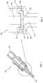
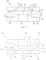
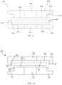
- FIG. 1shows a section view of a device, according to a first exemplary embodiment of the present invention
- FIG. 2shows an enlarged view of the device of FIG. 1 ;
- FIG. 3shows a cross-sectional side view of capture area of a device, according to a second exemplary embodiment of the present invention
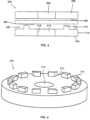
- FIG. 4shows a perspective view of a portion of a second housing of the device of FIG. 3 , according to a further embodiment
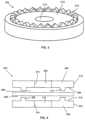
- FIG. 5shows a perspective view of a portion of the second housing of the device of FIG. 3 , according to an alternate embodiment
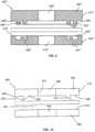
- FIG. 6shows a cross-sectional a side view of a capture area of a device, according to a third embodiment of the present invention.
- FIG. 7shows a cross-sectional side view of a capture area of a device, according to a fourth embodiment of the present invention.
- FIG. 8shows a cross-sectional side view of a capture area of the device of FIG. 7 , according to an alternative embodiment
- FIG. 9shows a cross-sectional side view of a capture area of the device of FIG. 8 , according to a further embodiment
- FIG. 10shows a cross-sectional side view of a capture area of a device, according to a fifth embodiment of the present invention.
- FIG. 11shows a cross-sectional side view of a capture area of a device, according to a sixth embodiment of the present invention.
- FIG. 12shows a cross-sectional side view of a capture area of a device, according to a seventh embodiment of the present invention.
- FIG. 13shows a cross-sectional side view of a capture area of a device, according to an eighth embodiment of the present invention.
- FIG. 14shows a cross-sectional side view of a capture area of a device, according to a ninth exemplary embodiment of the present invention.
- the present inventionmay be further understood with reference to the following description and the appended drawings, wherein like elements are referred to with the same reference numerals.
- the present inventionrelates to apparatus for controlling fluid flow through medical devices specifically for sealing devices which remain in place in the body to provide long term access to the vascular system.
- embodiments of the present inventioninclude features for fixing a disk and tuning the valve performance to withstand the increased pressures and flow rates associated with certain procedures.
- exemplary embodiments of the present inventionprovide features for enhancing the performance of a pressure activated valve including a feature fixing a slitted, flexible disk in a desired position, a relief well to accommodate portions of the flexible disk moved out of the fixation area and a sit bias feature creating a bias aiding in tuning the performance of the valve (e.g., to select a threshold activation pressure).
- a device 100comprises a first housing 102 and a second housing 104 coupled to one another to hold a disk 106 therebetween.
- the device 100may further comprise an additional capture component 108 , such as an o-ring.
- the first housing 102may, for example, be located at a proximal end 122 of the device 100 while the second housing 104 may be located at a distal end 124 of the device 100 .
- the first housing 102includes a lumen 110 extending therethrough and a disk-facing surface 112 .
- the second housing 104includes a lumen 114 extending therethrough and a disk-facing surface 116 .
- first housing 102 and the second housing 104are brought together to hold a disk 106 therebetween such that a pressure activated sit in the disk is positioned between the lumens 110 , 114 to control fluid communication therebetween.
- a circumference of the disk-facing surface 112 of the first housing 102 and the disk-facing surface 116 of the second housingmay be substantially the same as a circumference of the disk 106 so that the first housing 102 , the second housing 104 and the disk 106 are substantially aligned within the device 100 .
- the disk 106may, if desired, operate as a bidirectional valve allowing fluid flow through the device 100 in either direction.
- the disk 106may be structured or, one or both of the first and second housings 102 , 104 , respectively, may include a structure preventing the disk 106 from deforming in one direction and opening to permit fluid flow through the valve in that direction. Thus, fluid flow would be permitted only in the other direction. Fluid may be being administered to the body via the device 100 when a fluid pressure applied to the proximal end 122 of the device 100 exceeds a threshold value at which the disk 106 deforms so that the slit of the disk 106 opens to permit fluid flow therethrough to the distal end 124 of the device 100 .
- the slitremains open and fluid passes through the disk 106 and the lumen 112 to the body.
- Fluidmay be withdrawn from the body when a negative fluid pressure applied to the proximal end 122 exceeds the threshold level deforming the disk 106 and the slit thereof proximally to permit fluid flow from the distal end 124 of the device 100 to the proximal end 122 thereof.
- the fluidmay be drawn from the body through the lumen 112 of the second housing 104 . This fluid flow will be maintained so long as the fluid pressure remains at least the threshold value.
- the disk 106returns to the sealed configuration in which edges of the slit therethrough abut one another preventing fluid flow therethrough.
- the disk 106may be flexible such that the disk 106 may be held between the first housing 102 and the second housing 104 in a substantially planar configuration or in a deformed configuration, as shown in FIG. 2 .
- the capture component 108shown as an o-ring, may be housed between the first housing 102 and the second housing 104 such that when the disk 106 is held between the disk-facing surface 112 and the disk-facing surface 116 , an outer edge 118 of the disk 106 is deformed so that an outer edge 118 extends away from a plane of a central portion 120 of the disk 106 into a relief well 420 formed around a circumference of the disk facing surface 112 of the first housing 102 .
- the disk-facing surfaces and, between which the disk 106 is fixedmay be formed substantially planar to hold the central portion 120 in place without bending it in one direction or the other. It will be understood by those of skill in the art, however, that other factors such as diameter, may also affect the tuning of the valve.
- either or both of those portions of the disk-facing surfaces contacting the disk 106 and forming fixation features of the first and second housings 102 , 104 , respectively,may be coated, textured, covered or overmolded with a thermoplastic elastomer or thermoset plastic such as silicone to enhance the coefficient of friction to aid in valve disk retention during high now applications.
- the disk 106may be non-planar.
- the disk 106may have a concave or convex shape. It will be understood by those of skill in the art, however, that the disk 106 may take a variety of other non-planar shapes and forms so long as the disk 106 may be fixed between the first housing 102 and the second housing 104 . It will also be understood by those of skill in the art that the disk 106 may include more than one slit which may be pressure activated. Additionally, either of or both of the first and second housings 102 , 104 , respectively, may include more than one lumen extending therethrough. With flow through each of these lumens controlled by separate slits or by one or more common slits extending across multiple lumens.
- the following alternate embodimentsare substantially the same as the device 100 described above, but may include alternate geometrical aspects forming the fixation feature, the relief well and the slit bias.
- the first and second housings of the following embodimentsalign such that the lumen of the first housing is in fluid communication with the lumen of the second housing with a flexible disk secured therebetween so that a slit of the disk is positioned between the lumens to control fluid flow therebetween.
- the figuresshow a capture area of the device in which the disk would be held such that the device is depicted via surfaces of a distal portion of the first housing and a proximal portion of the second housing.
- a device 200comprises a first housing 202 and a second housing 204 for securing a disk (shown in broken lines) therebetween.
- the first housing 202includes a lumen 206 extending therethrough and a surface 208 , which faces a disk received in the space between the first and second housings 202 , 204 , respectively.
- the surface 208may be substantially planar so that an entire area thereof contacts the disk.
- the second housing 204includes a lumen 210 extending therethrough and a surface 212 facing the space in which the disk will be received.
- the surface 212may further include at least one protrusion 214 forming a fixation feature pressing against the surface 208 a portion of the disk abutting thereagainst.
- the protrusion 214may be formed as an annular ring encircling the lumen 210 radially within an outer circumference 216 of the second housing 204 with a circumference greater than an inner circumference of a wall 218 of the lumen 210 .
- the protrusion 214be formed by a continuous ring on the disk-facing surface 208 or, in an alternative embodiment, the protrusion 214 may be formed as a series of projections extending discontinuously around the lumen 210 (e.g., as a series of arcs extending along a curve around the lumen 210 .
- the non-continuous ring shapemay be formed by a series of castellated teeth of the disk-facing surface 208 of the second housing 204 .
- the non-continuous protrusion 214may be formed by a series of saw teeth. Such non-continuous geometries provide localized areas of grip on the disk. It will be understood by those of skill in the art that the protrusion 214 may be formed by any variety of geometrical shapes.
- a space 220 radially outside the protrusion 214(i.e., between the protrusion 214 and the outer circumference 216 ) forms a relief well into which a radially outer portion of the flexible disk will extend, substantially unsecured and enabled to flex accommodating the vibrations associated with high pressure fluid flow through the slit.
- a space 222 radially within the protrusion 214would allow a central portion of the disk, including the slitted portion, to flex toward the second housing 204 , until the central portion of the disk contacts the surface 212 .
- the device 200will be able to withstand increased fluid pressures when fluid flows through the device in a positive direction (from the first to the second housing).
- the slitis not biased in any particular direction when there is no fluid flow through the device 200 .
- the designation of the first housing 202 as upstream (i.e., proximal) of the second housing 204is exemplary only and may be reversed as may the location of the protrusion 214 . That is, the second housing 204 may be formed as either the proximal or distal end of the valve of the device 200 and the protrusion 214 may be formed on either of the first and second housings 202 , 204 , respectively, in either the proximal or the distal of the two.
- a device 300comprises a first housing 302 and a second housing 304 for holding a flexible disk (shown in broken lines) therebetween.
- the device 300is substantially similar to the device 200 , described above with the first housing 302 including a lumen 306 extending therethrough and a surface 308 which faces a space in which a disk will be received.
- the surface 308includes a protrusion 310 , which may extend around the lumen 306 continuously or non-continuously as described above in regard to device 200 .
- the protrusion 310has a circumference less than that of an outer circumference 312 of the first housing 302 but greater than an inner circumference 314 of the first housing 302 which forms the lumen 306 .
- the second housing 304includes a lumen 316 extending therethrough and a surface 318 which faces the space within which a disk will be received.
- the device 300differs from the device 200 , however, in that the surface 318 also includes a protrusion 320 which extends either continuously or discontinuously about the lumen 316 .
- a circumference of the protrusion 318is less than an outer circumference 322 of the second housing 304 but greater than an inner circumference 324 of the second housing 304 which forms the lumen 316 .
- the protrusion 310 of the first housing 302preferably substantially aligns with the protrusion 320 of the second housing 304 such that a disk held therebetween is gripped by the first and second housings 302 , 304 , respectively, with the protrusions 310 and 320 pressing portions of the disk inward toward one another.
- the protrusions 310 , 320form a fixation feature which holds the disk therebetween.
- a space 326 radially outside the protrusions 310 , 320forms a relief well allowing an outer portion of the disk to remain substantially unsecured therein to flex in either direction (i.e., toward the first housing 302 or toward the second housing 304 ) to accommodate the vibrations associated with high pressure fluid flow.
- a space 328 formed radially within the protrusions 310 , 320i.e., between the protrusions 310 , 320 and the lumens 306 , 316 ) allows a central portion of the disk, including the slitted portion, to flex to accommodate high pressure fluid flow.
- the central portion of the diskmay flex toward the first housing 302 until the disk contacts the disk-facing surface 308 and/or toward the second housing 304 until the disk contacts the disk-facing surface 318 .
- the space 328allows the disk to accommodate a high pressure fluid flow in either direction.
- the diskneed not be biased in any particular direction, either positive or negative.
- a device 400comprises a first housing 402 and a second housing 404 for holding a flexible disk (shown in broken lines) therebetween.
- the first housing 402includes a lumen 406 extending therethrough and a disk-facing surface 408 which includes a protrusion 410 extending from the surface 408 .
- the protrusion 410extends around the lumen 406 either continuously or non-continuously in the same manner described above radially within an outer circumference 412 of the first housing 402 and radially outside an inner circumference 414 of the first housing 402 which forms the lumen 406 .
- the protrusion 410may also include a pointed tip 426 , as shown in FIG. 7 .
- the protrusion 410may also be angled such that the pointed tip 426 is offset radially outward from a proximal end 432 at which the protrusion 410 meets the surface 408 . It will be understood by those of skill in the art that the pointed tip 426 may provide an improved grip of the disk 106 over a flat-surfaces protrusion 410 .
- the second housing 404includes a lumen 416 extending therethrough and forms a disk-facing surface 418 radially outside the lumen 416 .
- the disk-facing surface 418optionally includes an indentation 420 (or a series of indentations 420 if the protrusion 410 is non-continuous) corresponding to a shape of the protrusion 410 formed on the first housing 402 and angled similarly thereto.
- a device 400may include only a protrusion 410 without a corresponding indentation 420 and the same modification may be made to any of the devices 400 , 400 ′ and 400 ′′ described below.
- a device 400 ′ as shown in FIG. 8may include a protrusion 410 ′ and a corresponding indentation 420 ′ (or a series of non-continuous protrusions 410 ′ and indentations 420 ′) without the pointed tip of the device 400 .
- a protrusion 410 ′ and a corresponding indentation 420 ′or a series of non-continuous protrusions 410 ′ and indentations 420 ′
- the protrusion(s) 410 ′ and the indentation(s)may be substantially rectangular in cross-section to form similar radially outer and inner relief wells 428 ′ and 430 ′, respectively, in this case, a portion of a disk received between the first and second housings 402 ′, 404 ′, respectively, will be pushed by the protrusion(s) 410 ′ into the indentation(s) 420 ′, locking the disk in position with a slit therethrough aligned with the lumens 406 ′ and 416 ′ and so that the relief wells 428 ′ and 430 ′ allow for flexing of the disk and the accommodation of vibrations under high pressure fluid flow.
- the device 400 ′′ as shown in FIG. 9is constructed in substantially the same manner as the device 400 ′ except that the first housing 402 ′′ includes a second protrusion 434 ′′ on a disk facing surface 408 ′′ thereof which may be either continuous or non-continuous in the same manner described above for the protrusions of the previous embodiments while the second housing 404 ′′ includes a second indentation 436 ′′ on a disk-facing surface 418 ′′ thereof which may correspond in shape and position to the second protrusion 434 ′′.
- the device 400 ′′defines a radially outer relief well 428 ′′ between the first protrusion 410 and an outer circumference 412 ′′ of the first housing 402 ′′ and a radially inner relief well 430 ′′ between the second protrusion 434 ′′ and the lumen 406 ′′.
- first and the second housings 402 , 404respectively may include any number of protrusions and indentations as desired to more secure retain a disk gripped therebetween.
- a device 500comprises first and second housings 502 , 504 , respectively include disk facing surfaces 508 , 518 respectively for holding a flexible disk therebetween.
- the device 500is substantially similar to the device 400 , as described above except that, while the disk-facing surface 508 includes a protrusion 510 shaped and positioned substantially similarly to the projection 410 shown in FIG.
- the disk-facing surface 518 of the second housing 504includes no corresponding indentation and, in this case, is substantially planar such that, when a flexible disk is positioned between the first and second portions 502 , 504 , respectively, with a slit thereof aligned with the lumens 506 and 516 , portions of the disk contacting the protrusion(s) 510 are pinched against the flat surface 518 locking the disk in position while radially outer and inner relief wells 522 , 524 , respectively, allow for flexing of the disk and the accommodation of vibrations under high pressure fluid flow.
- a device 600comprises a first housing 602 and a second housing 604 for holding a flexible disk (shown in broken lines) therebetween.
- the first housing 602includes a lumen 606 extending therethrough and a disk-facing surface 608 .
- the disk-facing surface 608includes an inner portion 610 immediately surrounding the lumen 606 and an outer portion 612 extending radially from the inner portion 610 at a distal end of the lumen 606 .
- the outer portion 612may be substantially planar and oriented in any desired relationship to an axis of the lumen 606 (e.g., substantially perpendicular thereto).
- the inner portion 610is angled such that a proximal opening 606 ′ of the lumen 606 is smaller than a distal opening 606 ′′ thereof. That is, in this embodiment, the lumen 606 is substantially conical flaring outward distally.
- the second housing 604includes a lumen 614 extending therethrough to a proximal disk-facing surface 616 .
- the lumen 614may for example be substantially cylindrical and approximately equal in diameter to the proximal opening 606 ′ of the lumen 606 .
- the disk-facing surface 616includes a radially inner portion 618 separated from a radially outer portion 620 by a protrusion 622 which may be formed as described in regard to any of the above embodiments.
- the inner portion 618is angled so that, when the first and second housings 602 , 604 , respectively, are mated to one another with a slitted, flexible disk gripped therebetween, it is substantially parallel to the inner portion 610 of the first housing 602 .
- distal opening 606 ′′is wider than the proximal opening 614 ′
- the flexible disk(shown in broken lines) will preferably have a slit which is no wider than the opening 614 ′ and which, when gripped between the first and second housings 602 , 604 , respectively, will be entirely radially within the opening 614 ′ so that fluids will pass from the lumen 606 to the lumen 614 without leaking along the inner portion 618 .
- the protrusion 622extends continuously or non-continuously around the lumen 614 separated therefrom by the inner portion 618 and separated from an outer circumference 624 of the second housing 604 by an annular space forming a relief well 626 .
- the flexible diskwill bend to accommodate the angled inner portions 610 , 618 with a portion of the flexible disk secured between the outer portions 612 , 620 fixed to the outer portion 612 of the disk-facing surface 608 by the protrusion 622 .
- a central portion of the disk, including the slitted portionbends in a proximal direction.
- a device 700comprises a first housing 702 and a second housing 704 for holding a flexible disk (shown in broken lines) therebetween.
- the first housing 702includes a lumen 706 extending therethrough to a distal opening 706 ′ surrounded by a disk-facing surface 708 .
- An inner portion 710 of he disk-facing surface 708is substantially conical, angling proximally away from the opening 706 ′ to meet a substantially planar outer portion 712 extending radially outward therefrom.
- the second housing 704includes a substantially conical lumen 714 extending therethrough from a proximal opening 714 ′ to a smaller distal opening 714 ′′.
- the proximal opening 714 ′is surrounded by a disk-facing surface 716 separated from the opening 714 ′ by a protrusion 722 .
- the inner portion 718comprises a wall immediately surrounding the lumen 714 and is shaped, for example, to correspond to the shape of the inner portion 710 of the first housing 702 . That is, in this embodiment, the inner portion 718 is angled such that the lumen 714 is recessed relative to the outer portion 720 .
- the protrusion 722may extend continuously or non-continuously around the opening 714 ′ within an outer circumference 724 of the second housing 704 to define a relief well 726 within which will be received a radially outer portion of a slitted, flexible disk to be gripped between the first and second housings 702 , 704 , respectively.
- the diskwill be pinched between the projection 722 and the outer portion 712 and between the inner portions 710 and 718 leaving the radially outer portion of the disk free to vibrate when exposed to high flow rates.
- the flexible diskwill bend to accommodate the angled inner portions 710 , 718 of the disk facing surfaces 708 , 716 creating a positive slit bias reducing the pressure required for flow proximal to distal as compared to that required for flow from the distal to the proximal.
- a device 800comprises a first housing 802 and a second housing 804 for holding a flexible disk (shown in broken lines) therebetween.
- the first housing 802includes a lumen 806 extending therethrough and a disk-facing surface 808 including a recessed portion 810 extending around an outer-most perimeter of the disk-facing surface 808 . That is, a portion of the first housing 802 radially outside the disk-facing surface 808 is recessed away from the second housing relative to the disk-facing surface 808 .
- the second housing 804includes a lumen 812 extending therethrough and a disk-facing surface 814 which includes a non-continuous or continuous protrusion 816 as described above extending around an outer-most perimeter of the disk-facing surface 814 .
- a radially inner surface of the protrusion 816is radially further from the lumens 806 , 812 than the outer perimeter of the disk-facing surface 808 so that an annular gap extends there between when the first housing 802 is coupled to the second housing 804 with a flexible disk gripped therebetween.
- an o-ringmay be included in the device 800 as an alternative to the protrusion 816 .
- the o-ringmay be placed between the first and the second housings 802 , 804 when the disk is being fixed therebetween in substantially the same position described for the protrusion 816 .
- a circumference of the disk-contacting portion 818 of the disk-facing surface 808may be smaller than a circumference of the protrusion 816 on the disk-facing surface 814 such that when the first and second housing 802 , 804 are mated, a relief well 822 is formed by an annular space between an inner surface 824 of the protrusion 816 and an outer surface 826 of the disk-contacting portion 818 .
- the diskmay be fixed between the first and the second housings 802 , 804 , respectively, such that the disk-contacting portion 818 secures the disk to a disk-contacting portion 820 of the disk-facing surface 814 radially within the protrusion 816 .
- the diskmay be positioned therebetween such that the disk is substantially planar or, in the alternative, such that outer edges of the disk are deformed, as shown in FIG. 13 , by the protrusions 816 .
- an unsecured radially outer portion of the diskmay flex within the relief well 822 to accommodate high pressure fluid flow therethrough.
- the remaining portion of the diskis firmly secured between the disk-contacting portion 818 and the disk-contacting portion 820 , it will be understood by those of skill in the art that the a neutral slit bias exists, meaning that, in this embodiment, the device 800 opens to permit flow from proximal to distal at substantially the same threshold pressure as it opens to permit flow from distal to proximal.
- a device 900comprises a first housing 902 and a second housing 904 for securing a flexible disk (shown in broken lines) therebetween.
- the device 900is substantially similar to the device 800 described above except that the first housing 902 includes a protrusion 910 extending continuously or non-continuously around an outer-most perimeter of a disk-facing surface 908 as described above while the second housing 904 includes a recessed portion 914 extending around an outer-most perimeter of a disk-facing surface, radially outside a disk contacting portion 920 of the disk-facing surface 914 .
- the first housing 902includes a lumen 906 extending therethrough while the second housing 904 includes a lumen 912 extending therethrough.
- a circumference of the disk-contacting portion 920 of the disk facing surface 914is smaller than a circumference of the protrusion 910 on the disk-facing surface 908 such that, when the first and second housing 902 , 904 , respectively, are mated to one another, a relief well 922 is formed by an annular space between an inner surface 924 of the protrusion 910 and an outer surface 926 of the disk-contacting portion 920 .
- any of the features mentioned for a first housingmay be moved to a second housing and vice versa.
- features mentioned with respect to controlling flow in the distal to proximal directionmay be reversed to obtain the same effect in proximal to distal flow and vice versa.
- the present inventioncover any modifications that come within the scope of the appended claims and their equivalents.
Landscapes
- Engineering & Computer Science (AREA)
- Health & Medical Sciences (AREA)
- General Engineering & Computer Science (AREA)
- Heart & Thoracic Surgery (AREA)
- Mechanical Engineering (AREA)
- Anesthesiology (AREA)
- Hematology (AREA)
- Life Sciences & Earth Sciences (AREA)
- Animal Behavior & Ethology (AREA)
- General Health & Medical Sciences (AREA)
- Public Health (AREA)
- Veterinary Medicine (AREA)
- Biomedical Technology (AREA)
- Pulmonology (AREA)
- Infusion, Injection, And Reservoir Apparatuses (AREA)
- Safety Valves (AREA)
Abstract
Description
Claims (20)
Priority Applications (2)
| Application Number | Priority Date | Filing Date | Title |
|---|---|---|---|
| US15/240,430US11679248B2 (en) | 2008-05-21 | 2016-08-18 | Pressure activated valve for high flow rate and pressure venous access applications |
| US18/317,968US20230347130A1 (en) | 2008-05-21 | 2023-05-16 | Pressure activated valve for high flow rate and pressure venous access applications |
Applications Claiming Priority (3)
| Application Number | Priority Date | Filing Date | Title |
|---|---|---|---|
| US12/124,589US8257321B2 (en) | 2008-05-21 | 2008-05-21 | Pressure activated valve for high flow rate and pressure venous access applications |
| US13/566,386US9447892B2 (en) | 2008-05-21 | 2012-08-03 | Pressure activated valve for high flow rate and pressure venous access applications |
| US15/240,430US11679248B2 (en) | 2008-05-21 | 2016-08-18 | Pressure activated valve for high flow rate and pressure venous access applications |
Related Parent Applications (1)
| Application Number | Title | Priority Date | Filing Date |
|---|---|---|---|
| US13/566,386ContinuationUS9447892B2 (en) | 2008-05-21 | 2012-08-03 | Pressure activated valve for high flow rate and pressure venous access applications |
Related Child Applications (1)
| Application Number | Title | Priority Date | Filing Date |
|---|---|---|---|
| US18/317,968ContinuationUS20230347130A1 (en) | 2008-05-21 | 2023-05-16 | Pressure activated valve for high flow rate and pressure venous access applications |
Publications (3)
| Publication Number | Publication Date |
|---|---|
| US20160354599A1 US20160354599A1 (en) | 2016-12-08 |
| US20230029443A9 US20230029443A9 (en) | 2023-01-26 |
| US11679248B2true US11679248B2 (en) | 2023-06-20 |
Family
ID=41228426
Family Applications (4)
| Application Number | Title | Priority Date | Filing Date |
|---|---|---|---|
| US12/124,589Active2029-08-31US8257321B2 (en) | 2008-05-21 | 2008-05-21 | Pressure activated valve for high flow rate and pressure venous access applications |
| US13/566,386Active2030-03-19US9447892B2 (en) | 2008-05-21 | 2012-08-03 | Pressure activated valve for high flow rate and pressure venous access applications |
| US15/240,430Active2029-10-16US11679248B2 (en) | 2008-05-21 | 2016-08-18 | Pressure activated valve for high flow rate and pressure venous access applications |
| US18/317,968AbandonedUS20230347130A1 (en) | 2008-05-21 | 2023-05-16 | Pressure activated valve for high flow rate and pressure venous access applications |
Family Applications Before (2)
| Application Number | Title | Priority Date | Filing Date |
|---|---|---|---|
| US12/124,589Active2029-08-31US8257321B2 (en) | 2008-05-21 | 2008-05-21 | Pressure activated valve for high flow rate and pressure venous access applications |
| US13/566,386Active2030-03-19US9447892B2 (en) | 2008-05-21 | 2012-08-03 | Pressure activated valve for high flow rate and pressure venous access applications |
Family Applications After (1)
| Application Number | Title | Priority Date | Filing Date |
|---|---|---|---|
| US18/317,968AbandonedUS20230347130A1 (en) | 2008-05-21 | 2023-05-16 | Pressure activated valve for high flow rate and pressure venous access applications |
Country Status (4)
| Country | Link |
|---|---|
| US (4) | US8257321B2 (en) |
| EP (1) | EP2323726A2 (en) |
| CA (1) | CA2725157A1 (en) |
| WO (1) | WO2009143116A2 (en) |
Families Citing this family (27)
| Publication number | Priority date | Publication date | Assignee | Title |
|---|---|---|---|---|
| US6695817B1 (en) | 2000-07-11 | 2004-02-24 | Icu Medical, Inc. | Medical valve with positive flow characteristics |
| US7988679B2 (en) | 2003-03-18 | 2011-08-02 | Navilyst Medical, Inc. | Pressure responsive slit valve assembly for a plurality of fluids and uses thereof |
| US7435236B2 (en) | 2003-06-27 | 2008-10-14 | Navilyst Medical, Inc. | Pressure actuated valve with improved biasing member |
| US7252652B2 (en) | 2003-08-29 | 2007-08-07 | Boston Scientific Scimed, Inc. | Valved catheters including high flow rate catheters |
| US8187234B2 (en) | 2004-01-29 | 2012-05-29 | Navilyst Medical, Inc. | Pressure activated safety valve with anti-adherent coating |
| US9933079B2 (en) | 2004-01-29 | 2018-04-03 | Angiodynamics, Inc. | Stacked membrane for pressure actuated valve |
| US8034035B2 (en) | 2004-01-29 | 2011-10-11 | Navilyst Medical, Inc. | Pressure activated safety valve with high flow slit |
| US20060161115A1 (en) | 2004-11-05 | 2006-07-20 | Fangrow Thomas F | Soft-grip medical connector |
| US8328768B2 (en) | 2005-02-11 | 2012-12-11 | Angiodynamics, Inc | Pressure activated safety valve with improved flow characteristics and durability |
| US8585660B2 (en) | 2006-01-25 | 2013-11-19 | Navilyst Medical, Inc. | Valved catheter with power injection bypass |
| BRPI0717401A2 (en) | 2006-10-25 | 2013-11-12 | Icu Medical Inc | CONNECTOR FOR MEDICAL USE |
| US8257321B2 (en)* | 2008-05-21 | 2012-09-04 | Navilyst Medical, Inc. | Pressure activated valve for high flow rate and pressure venous access applications |
| US8337470B2 (en) | 2009-01-28 | 2012-12-25 | Angiodynamics, Inc. | Three-way valve for power injection in vascular access devices |
| US8083721B2 (en) | 2009-01-29 | 2011-12-27 | Navilyst Medical, Inc. | Power injection valve |
| WO2010107597A1 (en)* | 2009-03-19 | 2010-09-23 | Illinois Tool Works Inc. | One-way check valve |
| US8454579B2 (en) | 2009-03-25 | 2013-06-04 | Icu Medical, Inc. | Medical connector with automatic valves and volume regulator |
| US8007468B2 (en) | 2009-07-13 | 2011-08-30 | Navilyst Medical, Inc. | Method to secure an elastic component in a valve |
| USD644731S1 (en) | 2010-03-23 | 2011-09-06 | Icu Medical, Inc. | Medical connector |
| US8758306B2 (en) | 2010-05-17 | 2014-06-24 | Icu Medical, Inc. | Medical connectors and methods of use |
| JP6126530B2 (en) | 2010-11-01 | 2017-05-10 | ジーイー・ヘルスケア・リミテッド | Aseptic dispenser |
| US9895524B2 (en) | 2012-07-13 | 2018-02-20 | Angiodynamics, Inc. | Fluid bypass device for valved catheters |
| AU2014364218B2 (en) | 2013-12-11 | 2019-06-06 | Icu Medical, Inc. | Check valve |
| USD793551S1 (en) | 2014-12-03 | 2017-08-01 | Icu Medical, Inc. | Fluid manifold |
| USD786427S1 (en) | 2014-12-03 | 2017-05-09 | Icu Medical, Inc. | Fluid manifold |
| JP6365474B2 (en)* | 2015-09-11 | 2018-08-01 | トヨタ自動車株式会社 | Manufacturing method of secondary battery |
| US10610678B2 (en) | 2016-08-11 | 2020-04-07 | Angiodynamics, Inc. | Bi-directional, pressure-actuated medical valve with improved fluid flow control and method of using such |
| IT201700026909A1 (en)* | 2017-03-10 | 2018-09-10 | Freni Brembo Spa | Valve assembly for braking system |
Citations (317)
| Publication number | Priority date | Publication date | Assignee | Title |
|---|---|---|---|---|
| US26235A (en) | 1859-11-22 | Henry m | ||
| US500745A (en) | 1893-07-04 | Woodbury o | ||
| US1142525A (en) | 1914-06-11 | 1915-06-08 | Continental Gas Compressing Corp | Apparatus for obtaining liquid hydrocarbons. |
| US1244379A (en) | 1917-02-19 | 1917-10-23 | William I Short | Fuel-mixing safety throttle-valve. |
| US1989145A (en) | 1933-10-06 | 1935-01-29 | Neal D Newby | Cap for collapsible tubes |
| US2122299A (en) | 1937-09-20 | 1938-06-28 | Evan Hughes A | Dispensing top |
| US2446571A (en) | 1944-03-02 | 1948-08-10 | American Brake Shoe Co | Check valve |
| US2720881A (en) | 1953-06-08 | 1955-10-18 | Jones John Leslie | Closure |
| US2755060A (en) | 1951-12-03 | 1956-07-17 | Twyman L Raymond | Reinforced flexible wall valve structure |
| US2841166A (en) | 1955-12-30 | 1958-07-01 | John M Auzin | Combination valve and plug |
| US3020913A (en) | 1958-07-15 | 1962-02-13 | William T Heyer | Surgical drain |
| US3111125A (en) | 1961-11-06 | 1963-11-19 | Rudolf R Schulte | Drainage device |
| US3113586A (en) | 1962-09-17 | 1963-12-10 | Physio Control Company Inc | Artificial heart valve |
| US3118468A (en) | 1961-04-20 | 1964-01-21 | Gen Electric | Resilient material check valve |
| US3159175A (en) | 1961-12-12 | 1964-12-01 | Delman Co | Fluid check valve unit |
| US3159176A (en) | 1962-12-07 | 1964-12-01 | Vernay Laboratories | Check-relief valve |
| USRE26235E (en) | 1967-07-18 | Woodfordvacuum breaker | ||
| US3422844A (en) | 1965-03-05 | 1969-01-21 | Grimar Inc | Flexible check valve |
| US3477438A (en) | 1967-04-17 | 1969-11-11 | Dwight L Allen | Catheter having one-way inflations valve |
| US3514438A (en) | 1969-06-06 | 1970-05-26 | Amicon Corp | Antithrombogenic materials |
| US3525357A (en) | 1968-11-18 | 1970-08-25 | Waters Co The | Pump valve apparatus |
| US3621557A (en) | 1969-06-06 | 1971-11-23 | Rex Chainbelt Inc | Insert for sandwich panels and method of installation |
| US3662955A (en) | 1969-06-06 | 1972-05-16 | Michinobu Takanashi | Length of watering hose for cultivating plants |
| US3669323A (en) | 1969-12-12 | 1972-06-13 | American Can Co | One-way valve insert for collapsible dispensing containers |
| US3674183A (en) | 1971-02-01 | 1972-07-04 | Herny B Venable | Dispensing device |
| US3673612A (en) | 1970-08-28 | 1972-07-04 | Massachusetts Inst Technology | Non-thrombogenic materials and methods for their preparation |
| US3710942A (en) | 1967-06-02 | 1973-01-16 | Pall Corp | Valve for fluid lines and structures containing the same |
| US3788327A (en) | 1971-03-30 | 1974-01-29 | H Donowitz | Surgical implant device |
| US3811466A (en) | 1972-04-06 | 1974-05-21 | J Ohringer | Slit diaphragm valve |
| US3827456A (en) | 1970-08-21 | 1974-08-06 | W Sheppard | Fluid valves |
| US3848579A (en) | 1973-02-23 | 1974-11-19 | Real A Villa | Automatic elasto-valvular hypodermic sampling needle |
| US3885561A (en) | 1971-12-15 | 1975-05-27 | Charles N Mazal Cami | Catheter |
| US3888249A (en) | 1973-11-02 | 1975-06-10 | David L Spencer | Arterial infusion catheter |
| US3941149A (en) | 1974-11-11 | 1976-03-02 | Baxter Laboratories, Inc. | Valve |
| US3955594A (en) | 1974-02-25 | 1976-05-11 | Raymond International Inc. | Pressure operated valve systems |
| US3964509A (en) | 1975-02-14 | 1976-06-22 | Da/Pro Rubber, Inc. | Check valve |
| US4000740A (en) | 1974-05-31 | 1977-01-04 | Baxter Travenol Laboratories, Inc. | Injection site |
| US4072146A (en) | 1976-09-08 | 1978-02-07 | Howes Randolph M | Venous catheter device |
| US4134402A (en) | 1976-02-11 | 1979-01-16 | Mahurkar Sakharam D | Double lumen hemodialysis catheter |
| US4137152A (en) | 1977-11-10 | 1979-01-30 | Mobil Oil Corporation | Selective high conversion cracking process |
| US4142525A (en) | 1977-03-10 | 1979-03-06 | The Kendall Company | Syringe assembly |
| US4143853A (en)* | 1977-07-14 | 1979-03-13 | Metatech Corporation | Valve for use with a catheter or the like |
| US4176678A (en) | 1976-12-06 | 1979-12-04 | Regie Nationale Des Usines Renault | Safety device for venting a fuel tank |
| US4232677A (en) | 1977-06-07 | 1980-11-11 | Saul Leibinsohn | Microbe-barrier drainage device |
| US4244379A (en) | 1979-08-02 | 1981-01-13 | Quest Medical, Inc. | Check valve for blood drawing apparatus |
| JPS576863A (en) | 1980-06-13 | 1982-01-13 | Matsushita Electric Ind Co Ltd | Illumination device of electrophotographic copying machine |
| US4327722A (en) | 1979-08-20 | 1982-05-04 | Groshong Leroy E | Methods and apparatus for intravenous therapy and hyperalimentation |
| DE3048203A1 (en) | 1980-12-20 | 1982-07-01 | B. Braun Melsungen Ag, 3508 Melsungen | Blood vessel puncturing instrument union piece - has non return valve opening under low pressure |
| US4342315A (en) | 1979-05-10 | 1982-08-03 | Mallinckrodt, Inc. | Suction catheters with improved suction control valve |
| FR2508008A1 (en) | 1981-06-17 | 1982-12-24 | Otk Keskusosuusliike | FLUID DISPENSER WITH SPOUT |
| US4387879A (en) | 1978-04-19 | 1983-06-14 | Eduard Fresenius Chemisch Pharmazeutische Industrie Kg | Self-sealing connector for use with plastic cannulas and vessel catheters |
| US4405316A (en) | 1978-04-03 | 1983-09-20 | Baxter Travenol Laboratories, Inc. | Injection site with check valve inlet |
| US4417888A (en) | 1982-03-15 | 1983-11-29 | Renal Systems, Inc. | Percutaneous implant |
| US4424058A (en) | 1981-11-23 | 1984-01-03 | Parsons Robert L | Drainage control method and apparatus |
| US4424833A (en)* | 1981-10-02 | 1984-01-10 | C. R. Bard, Inc. | Self sealing gasket assembly |
| US4431426A (en) | 1979-08-20 | 1984-02-14 | Groshong Leroy E | Methods and apparatus for intravenous therapy and hyperalimentation |
| US4434810A (en) | 1980-07-14 | 1984-03-06 | Vernay Laboratories, Inc. | Bi-directional pressure relief valve |
| US4447237A (en) | 1982-05-07 | 1984-05-08 | Dow Corning Corporation | Valving slit construction and cooperating assembly for penetrating the same |
| JPS59133877A (en) | 1983-01-18 | 1984-08-01 | Terumo Corp | Valve element |
| US4465102A (en) | 1982-05-17 | 1984-08-14 | The Warren Rupp Company | Check valve |
| US4468224A (en) | 1982-01-28 | 1984-08-28 | Advanced Cardiovascular Systems, Inc. | System and method for catheter placement in blood vessels of a human patient |
| US4475898A (en) | 1982-04-26 | 1984-10-09 | American Hospital Supply Corporation | Fetal ventriculo-amniotic shunt |
| EP0128525A2 (en) | 1983-06-07 | 1984-12-19 | Lingner + Fischer GmbH | Closure for containers, particularly for tubes, and its applications |
| EP0128625A1 (en) | 1983-06-13 | 1984-12-19 | Koninklijke Philips Electronics N.V. | Magnetic transducing head for writing information on high-coercive recording media |
| US4502502A (en) | 1982-09-22 | 1985-03-05 | C. R. Bard, Inc. | Overpressure safety valve |
| JPS6088562A (en) | 1983-10-22 | 1985-05-18 | テルモ株式会社 | Puncture needle with valve body |
| US4524805A (en) | 1983-07-08 | 1985-06-25 | Hoffman Allan C | Normally closed duckbill valve and method of manufacture |
| US4529399A (en) | 1983-05-03 | 1985-07-16 | Catheter Technology Corporation | Method and apparatus for placing a catheter |
| US4543087A (en) | 1983-11-14 | 1985-09-24 | Quinton Instrument Company | Double lumen catheter tip |
| US4549879A (en) | 1983-05-03 | 1985-10-29 | Catheter Technology Corporation | Valved two-way catheter |
| US4552553A (en) | 1983-06-30 | 1985-11-12 | Pudenz-Schulte Medical Research Corp. | Flow control valve |
| US4559046A (en) | 1979-08-20 | 1985-12-17 | Catheter Technology Corporation | Apparatus for intravenous therapy and hyperalimentation |
| US4610276A (en) | 1982-09-29 | 1986-09-09 | Nypro Inc. | Directional flow control |
| US4610665A (en) | 1983-01-18 | 1986-09-09 | Terumo Kabushiki Kaisha | Medical instrument |
| EP0198962A1 (en) | 1984-12-28 | 1986-10-29 | TERUMO KABUSHIKI KAISHA trading as TERUMO CORPORATION | Valve device for a medical instrument |
| US4625245A (en) | 1983-12-12 | 1986-11-25 | White R Kent | Magnetic recording |
| US4626245A (en) | 1985-08-30 | 1986-12-02 | Cordis Corporation | Hemostatis valve comprising an elastomeric partition having opposed intersecting slits |
| US4646945A (en)* | 1985-06-28 | 1987-03-03 | Steiner Company, Inc. | Vented discharge assembly for liquid soap dispenser |
| US4668221A (en) | 1985-03-28 | 1987-05-26 | Luther Medical Products, Inc. | Assembly of stylet and catheter |
| US4671796A (en) | 1983-05-03 | 1987-06-09 | Catheter Technology Corp. | Valved two-way catheter |
| US4681572A (en) | 1982-09-13 | 1987-07-21 | Hollister Incorporated | Female urinary incontinence device |
| US4692141A (en) | 1982-03-08 | 1987-09-08 | Mahurkar Sakharam D | Double lumen catheter |
| US4692146A (en) | 1985-10-24 | 1987-09-08 | Cormed, Inc. | Multiple vascular access port |
| US4701166A (en) | 1983-05-03 | 1987-10-20 | Catheter Technology Corp. | Valved two-way catheter |
| US4722725A (en) | 1983-04-12 | 1988-02-02 | Interface Biomedical Laboratories, Inc. | Methods for preventing the introduction of air or fluid into the body of a patient |
| US4728006A (en) | 1984-04-27 | 1988-03-01 | The Procter & Gamble Company | Flexible container including self-sealing dispensing valve to provide automatic shut-off and leak resistant inverted storage |
| US4737152A (en) | 1986-07-02 | 1988-04-12 | Becton, Dickinson And Company | Catheter assembly |
| US4753640A (en) | 1986-10-06 | 1988-06-28 | Catheter Technology Corporation | Catheters and methods |
| JPS63255057A (en) | 1987-03-20 | 1988-10-21 | ジャン・コロン | Valve |
| US4790817A (en) | 1985-03-28 | 1988-12-13 | Luther Medical Products, Inc. | Assembly of stylet and catheter, and needle and catheter |
| US4790832A (en) | 1986-06-06 | 1988-12-13 | Icu Medical, Inc. | System for administering medication nasally to a patient |
| US4798594A (en) | 1987-09-21 | 1989-01-17 | Cordis Corporation | Medical instrument valve |
| US4801297A (en) | 1984-06-01 | 1989-01-31 | Edward Weck Incorporated | Catheter having slit tip |
| US4809679A (en) | 1986-11-19 | 1989-03-07 | Olympus Optical Co., Ltd. | Forceps plug for endoscopes |
| US4813934A (en) | 1987-08-07 | 1989-03-21 | Target Therapeutics | Valved catheter device and method |
| US4842591A (en) | 1988-01-21 | 1989-06-27 | Luther Ronald B | Connector with one-way septum valve, and assembly |
| EP0337617A2 (en) | 1988-04-12 | 1989-10-18 | H.G. Wallace Limited | Pressure actuated valve particularly for biological use |
| JPH0231967A (en) | 1988-07-19 | 1990-02-01 | Suzuki Motor Co Ltd | Device for sliding seat |
| JPH02102659A (en) | 1988-10-12 | 1990-04-16 | Nissho Corp | Plant-type thoracic duct and vein shunt |
| EP0366814A1 (en) | 1988-05-16 | 1990-05-09 | Terumo Kabushiki Kaisha | Subcutaneously implanted catheter assembly |
| US4944726A (en) | 1988-11-03 | 1990-07-31 | Applied Vascular Devices | Device for power injection of fluids |
| US4946448A (en)* | 1989-10-23 | 1990-08-07 | Kendall Mcgaw Laboratories, Inc. | Check valve for use with intravenous pump |
| US4950252A (en) | 1987-11-02 | 1990-08-21 | Luther Medical Products, Inc. | Single hand actuated locking safety catheter and method of use |
| US4960412A (en) | 1988-04-15 | 1990-10-02 | Universal Medical Instrument Corp. | Catheter introducing system |
| US4973319A (en) | 1989-05-10 | 1990-11-27 | Therex Corp. | Slit valve medical catheter |
| US4986814A (en) | 1988-06-13 | 1991-01-22 | Indianapolis Center For Advanced Research | One-punch catheter |
| US4991745A (en) | 1989-04-25 | 1991-02-12 | Liquid Molding Systems, Inc. | Dispensing valve with trampoline-like construction |
| US4994046A (en) | 1988-12-30 | 1991-02-19 | Vann T. Wesson | Needle guard for syringe |
| US4995863A (en) | 1986-10-06 | 1991-02-26 | Catheter Technology Corporation | Catheter with slit valve |
| US4998919A (en) | 1987-10-31 | 1991-03-12 | Schnepp Pesch Wolfram | Thrombectomy apparatus |
| US5000745A (en)* | 1988-11-18 | 1991-03-19 | Edward Weck Incorporated | Hemostatis valve |
| US5009391A (en) | 1988-05-02 | 1991-04-23 | The Kendall Company | Valve assembly |
| US5030210A (en) | 1988-02-08 | 1991-07-09 | Becton, Dickinson And Company | Catheter valve assembly |
| US5062836A (en) | 1990-03-14 | 1991-11-05 | The Kendall Company | Placement device for a catheter and guide wire |
| US5085635A (en) | 1990-05-18 | 1992-02-04 | Cragg Andrew H | Valved-tip angiographic catheter |
| EP0474069A1 (en) | 1990-09-04 | 1992-03-11 | H. Robert Moorehead | Two-way outdwelling slit valve assembly |
| US5098405A (en) | 1991-01-31 | 1992-03-24 | Becton, Dickinson And Company | Apparatus and method for a side port cathether adapter with a one piece integral combination valve |
| WO1992006732A1 (en) | 1990-10-10 | 1992-04-30 | Strato Medical Corporation | Check valve catheter |
| US5125893A (en) | 1990-04-16 | 1992-06-30 | Dryden Gale E | Suction catheter with wall lumen for irrigation |
| US5143853A (en) | 1986-06-25 | 1992-09-01 | Trustees Of Tufts College | Absorbance modulated fluorescence detection methods and sensors |
| US5147332A (en) | 1991-05-17 | 1992-09-15 | C.R. Bard, Inc. | Multi-valve catheter for improved reliability |
| US5149327A (en) | 1989-09-05 | 1992-09-22 | Terumo Kabushiki Kaisha | Medical valve, catheter with valve, and catheter assembly |
| US5167638A (en) | 1989-10-27 | 1992-12-01 | C. R. Bard, Inc. | Subcutaneous multiple-access port |
| US5169393A (en) | 1990-09-04 | 1992-12-08 | Robert Moorehead | Two-way outdwelling slit valving of medical liquid flow through a cannula and methods |
| US5176662A (en) | 1990-08-23 | 1993-01-05 | Minimed Technologies, Ltd. | Subcutaneous injection set with improved cannula mounting arrangement |
| US5176652A (en) | 1989-12-22 | 1993-01-05 | Cordis Corporation | Hemostasis valve |
| JPH0528351A (en) | 1991-07-19 | 1993-02-05 | Fuji Electric Co Ltd | Structure for holding sample products in the display room of vending machines |
| US5201772A (en) | 1991-01-31 | 1993-04-13 | Maxwell Scott M | System for resisting limb movement |
| US5205834A (en) | 1990-09-04 | 1993-04-27 | Moorehead H Robert | Two-way outdwelling slit valving of medical liquid flow through a cannula and methods |
| US5215538A (en) | 1992-02-05 | 1993-06-01 | Abbott Laboratories | Connector-activated in-line valve |
| US5249598A (en) | 1992-08-03 | 1993-10-05 | Vernay Laboratories, Inc. | Bi-directional vent and overpressure relief valve |
| US5253765A (en) | 1993-01-14 | 1993-10-19 | L.M.B. Electronics, Inc. | Sorting and grading system |
| US5254086A (en) | 1992-07-31 | 1993-10-19 | Ballard Medical Products | Medical lavage apparatus and methods |
| US5255676A (en) | 1991-11-08 | 1993-10-26 | Russo Ronald D | Safety sealed tracheal suction system |
| JPH0645671A (en) | 1992-07-24 | 1994-02-18 | Nec Corp | Semiconductor laser drive circuit |
| JPH06121499A (en) | 1992-10-01 | 1994-04-28 | Toshiba Corp | Molded motor manufacturing method |
| US5324274A (en) | 1992-03-30 | 1994-06-28 | Med-Pro Design, Inc. | Catheter having rotary valves |
| US5336203A (en) | 1993-05-28 | 1994-08-09 | Abbott Laboratories | Low profile gastrostomy device with dome |
| US5360407A (en) | 1991-08-29 | 1994-11-01 | C. R. Bard, Inc. | Implantable dual access port with tactile ridge for position sensing |
| US5370624A (en) | 1993-09-14 | 1994-12-06 | Becton Dickinson And Company | Catheter with deactivatable side port |
| US5395352A (en) | 1992-02-24 | 1995-03-07 | Scimed Lift Systems, Inc. | Y-adaptor manifold with pinch valve for an intravascular catheter |
| US5396925A (en) | 1993-12-16 | 1995-03-14 | Abbott Laboratories | Anti-free flow valve, enabling fluid flow as a function of pressure and selectively opened to enable free flow |
| US5399168A (en) | 1991-08-29 | 1995-03-21 | C. R. Bard, Inc. | Implantable plural fluid cavity port |
| US5401255A (en) | 1993-07-20 | 1995-03-28 | Baxter International Inc. | Multi-functional valve with unitary valving member and improved safety |
| US5405340A (en) | 1992-10-07 | 1995-04-11 | Abbott Laboratories | Threaded securing apparatus for flow connectors |
| USD357735S (en) | 1993-08-03 | 1995-04-25 | I-Flow Corporation | Valve for filling an IV solution bag |
| US5411491A (en) | 1993-05-28 | 1995-05-02 | Abbott Laboratories | Low profile gastrostomy device with one-way cross-slit valve |
| WO1995016480A1 (en) | 1993-12-13 | 1995-06-22 | Migada, Inc. | Medical infusion apparatus including safety valve |
| US5453097A (en)* | 1994-08-15 | 1995-09-26 | Paradis; Joseph R. | Control of fluid flow |
| US5454784A (en) | 1994-06-10 | 1995-10-03 | Zimmer, Inc. | Control valve for a fluid set |
| FR2718969A1 (en) | 1994-04-21 | 1995-10-27 | Balt Extrusion | Catheter safety device, avoiding excessive pressure during injection |
| US5469805A (en) | 1992-08-22 | 1995-11-28 | Keystone International Holdings Corp. | High visibility valve position indicator |
| US5470305A (en) | 1993-04-19 | 1995-11-28 | Stryker Corporation | Irrigation handpiece with built in pulsing pump |
| US5484420A (en) | 1992-07-09 | 1996-01-16 | Wilson-Cook Medical Inc. | Retention bolsters for percutaneous catheters |
| WO1996017190A1 (en) | 1994-12-02 | 1996-06-06 | Ideal-Standard Gmbh | Flow limiter |
| WO1996023158A1 (en) | 1995-01-26 | 1996-08-01 | Vernay Laboratories, Inc. | Medical coupling site valve body |
| US5542923A (en) | 1990-03-01 | 1996-08-06 | Michigan Transtech Corporation | Implantable access devices |
| US5545150A (en) | 1994-05-06 | 1996-08-13 | Endoscopic Concepts, Inc. | Trocar |
| US5554136A (en) | 1994-09-07 | 1996-09-10 | Luther Medical Products, Inc. | Dual lumen infusion/aspiration catheter |
| US5562618A (en) | 1994-01-21 | 1996-10-08 | Sims Deltec, Inc. | Portal assembly and catheter connector |
| US5571093A (en) | 1994-09-21 | 1996-11-05 | Cruz; Cosme | Multiple-lumen catheter |
| US5575769A (en) | 1995-05-30 | 1996-11-19 | Vaillancourt; Vincent L. | Cannula for a slit septum and a lock arrangement therefore |
| JPH0938198A (en) | 1995-07-25 | 1997-02-10 | Shigenobu Takane | Rectal catheter |
| US5619393A (en) | 1994-08-01 | 1997-04-08 | Texas Instruments Incorporated | High-dielectric-constant material electrodes comprising thin ruthenium dioxide layers |
| US5624395A (en) | 1995-02-23 | 1997-04-29 | Cv Dynamics, Inc. | Urinary catheter having palpitatable valve and balloon and method for making same |
| US5637099A (en) | 1994-06-09 | 1997-06-10 | Durdin; Daniel J. | Needle handling apparatus and methods |
| WO1997023255A1 (en) | 1995-12-21 | 1997-07-03 | B.Braun Celsa | Catheter having a valve with bidirectional axial slits |
| WO1997026931A1 (en) | 1996-01-23 | 1997-07-31 | Florence Stinger | Softening conduit for carrying fluids into and out of the human body |
| US5743894A (en) | 1995-06-07 | 1998-04-28 | Sherwood Medical Company | Spike port with integrated two way valve access |
| US5743884A (en) | 1992-12-17 | 1998-04-28 | Hasson; Harrith M. | Sealing structure for medical instrument |
| US5752928A (en) | 1997-07-14 | 1998-05-19 | Rdo Medical, Inc. | Glaucoma pressure regulator |
| US5752938A (en) | 1994-09-12 | 1998-05-19 | Richard-Allan Medical Industries, Inc. | Seal for surgical instruments |
| WO1998022178A1 (en) | 1996-11-18 | 1998-05-28 | Nypro, Inc. | Swabbable luer-coned valve |
| US5769107A (en) | 1996-03-28 | 1998-06-23 | American Cyanamid Company | Valve system, particularly for use with termiticide systems |
| US5803078A (en) | 1994-05-06 | 1998-09-08 | Brauner; Mark E. | Methods and apparatus for intrapulmonary therapy and drug administration |
| US5807349A (en) | 1997-03-10 | 1998-09-15 | United States Surgical Corporation | Catheter having valve mechanism |
| US5810789A (en) | 1996-04-05 | 1998-09-22 | C. R. Bard, Inc. | Catheters with novel lumen shapes |
| US5843044A (en) | 1997-06-16 | 1998-12-01 | Catheter Innovations | Outdwelling slit valve and variable control for controlling opening and closing the slit |
| EP0882466A2 (en) | 1997-06-05 | 1998-12-09 | Disetronic Licensing AG | Device for the dosed application of a liquid drug |
| US5853397A (en) | 1993-12-13 | 1998-12-29 | Migada, Inc. | Medical infusion apparatus including safety valve |
| US5858003A (en) | 1994-10-20 | 1999-01-12 | Children's Medical Center Corporation | Systems and methods for promoting tissue growth |
| US5865308A (en) | 1996-10-29 | 1999-02-02 | Baxter International Inc. | System, method and device for controllably releasing a product |
| US5868703A (en) | 1996-04-10 | 1999-02-09 | Endoscopic Technologies, Inc. | Multichannel catheter |
| WO1999042166A1 (en) | 1998-02-18 | 1999-08-26 | C. R. Bard, Inc. | Dual reservoir vascular access port with two-piece housing and compound septum |
| US5944698A (en) | 1997-10-14 | 1999-08-31 | Ultradent Products, Inc. | Adjustable flow syringe |
| US5989233A (en) | 1996-03-19 | 1999-11-23 | Yoon; Inbae | Endoscopic portal having a universal seal and methods for introducing instruments therethrough |
| WO2000006230A1 (en) | 1998-07-27 | 2000-02-10 | Mclaughlin David L | Wrist-mounted i.v. administration set |
| US6033393A (en) | 1996-12-31 | 2000-03-07 | Johnson & Johnson Medical, Inc. | Method and apparatus for overpressure protection of a catheter |
| US6045734A (en) | 1995-05-24 | 2000-04-04 | Becton Dickinson And Company | Process of making a catheter |
| US6050934A (en) | 1997-02-26 | 2000-04-18 | Cv Dynamics, Inc. | Urinary catheter having palpitatable discharge valve with protective shoulders |
| US6056717A (en) | 1994-01-18 | 2000-05-02 | Vasca, Inc. | Implantable vascular device |
| US6062244A (en) | 1998-08-13 | 2000-05-16 | Aci Medical | Fluidic connector |
| US6081106A (en) | 1998-08-21 | 2000-06-27 | Cisco Technology, Inc. | Voltage setpoint error reduction |
| EP1016431A1 (en) | 1992-09-04 | 2000-07-05 | Michigan Transtech Corporation | Implantable access devices |
| US6092551A (en) | 1998-05-19 | 2000-07-25 | Chesebrough-Pond's Usa Co., Division Of Conopco, Inc. | Duckbill valve |
| WO2000044419A1 (en) | 1999-01-28 | 2000-08-03 | Vasca, Inc. | Method and apparatus for percutaneously accessing a pressure activated implanted port |
| US6099505A (en) | 1993-07-13 | 2000-08-08 | Symbiosis Corporation | Valve assembly with automatic valve |
| US6110154A (en) | 1996-10-08 | 2000-08-29 | Hakko Electric Machine Works, Co. Ltd. | Valve and valved trocar jacket tube |
| US6120483A (en) | 1997-10-01 | 2000-09-19 | Boston Scientific Corporation | Medical fluid infusion and aspiration |
| JP2000279527A (en) | 1999-03-31 | 2000-10-10 | Terumo Corp | Indwelling needle assembly and valve element |
| JP2000514671A (en) | 1996-06-12 | 2000-11-07 | バイオリンク コーポレーション | Subcutaneous access device |
| US6152129A (en) | 1996-08-14 | 2000-11-28 | Resmed Limited | Determination of leak and respiratory airflow |
| US6152909A (en) | 1996-05-20 | 2000-11-28 | Percusurge, Inc. | Aspiration system and method |
| US6167886B1 (en) | 1997-05-28 | 2001-01-02 | Medi-Globe Vertriebs Gmbh | Device for treatment of male and female urinary incontinence |
| US6171287B1 (en) | 1998-05-29 | 2001-01-09 | Lawrence A. Lynn | Luer receiver and method for fluid transfer |
| US6210366B1 (en) | 1996-10-10 | 2001-04-03 | Sanfilippo, Ii Dominic Joseph | Vascular access kit |
| JP2001104486A (en) | 1999-10-06 | 2001-04-17 | Nippon Sherwood Medical Industries Ltd | Double lumen catheter |
| US6227200B1 (en) | 1998-09-21 | 2001-05-08 | Ballard Medical Products | Respiratory suction catheter apparatus |
| US6270489B1 (en) | 1999-07-01 | 2001-08-07 | Catheter Innovations, Inc. | Anti-clotting methods and apparatus for indwelling catheter tubes |
| US6296316B1 (en) | 1999-12-01 | 2001-10-02 | Illinois Tool Works Inc. | Adjustable headrest guide |
| US6306124B1 (en) | 1995-11-13 | 2001-10-23 | Micro Therapeutics, Inc. | Microcatheter |
| US20010037079A1 (en) | 1997-02-14 | 2001-11-01 | Burbank Jeffrey H. | Hemofiltration system |
| US6322541B2 (en)* | 1999-09-10 | 2001-11-27 | Scimed Life Systems, Inc. | Vascular introducer sheath and hemostasis valve for use therewith |
| US20020010425A1 (en) | 2000-01-25 | 2002-01-24 | Daig Corporation | Hemostasis valve |
| JP2002505927A (en) | 1998-03-10 | 2002-02-26 | ヴァーネイ・ラボラトリーズ・インコーポレーテッド | Hemostatic valve assembly with guide wire seal |
| US20020026145A1 (en) | 1997-03-06 | 2002-02-28 | Bagaoisan Celso J. | Method and apparatus for emboli containment |
| US6364861B1 (en) | 1998-09-17 | 2002-04-02 | Porex Medical Products, Inc. | Multi-valve injection/aspiration manifold |
| US6375637B1 (en) | 1999-08-27 | 2002-04-23 | Gore Enterprise Holdings, Inc. | Catheter balloon having a controlled failure mechanism |
| US6415793B1 (en) | 1999-01-04 | 2002-07-09 | John Kretz | Dual direction valve system |
| US20020111662A1 (en) | 2001-02-09 | 2002-08-15 | Iaizzo Paul A. | System and method for placing an implantable medical device within a body |
| US6442415B1 (en) | 1999-08-12 | 2002-08-27 | Magnetic Moments, L.L.C. | Contrast-enhanced coronary artery and coronary artery bypass graft imaging using an aortic root catheter injection with either magnetic resonance angiography or computed tomographic angiography |
| US20020121530A1 (en) | 2001-03-02 | 2002-09-05 | Socier Timothy R. | Multiple orifice valve |
| US6446671B2 (en) | 2000-08-04 | 2002-09-10 | John G. Armenia | Double wall safety hose |
| US20020156430A1 (en) | 2001-04-19 | 2002-10-24 | Haarala Brett T. | Catheter slit valves |
| US20020157664A1 (en) | 2001-03-12 | 2002-10-31 | Eric Fugelsang | Canister inhaler having a spacer and easy to operate lever mechanism and a flexible, elastic mouthpiece |
| DE20208420U1 (en) | 2002-05-25 | 2002-10-31 | Diez, Claudius, 06114 Halle | Pressure relief cylinder for vascular surgery |
| US20020193752A1 (en) | 1994-04-22 | 2002-12-19 | Lynn Lawrence A. | Medical valve |
| US20030014015A1 (en) | 2001-07-16 | 2003-01-16 | Scimed Life Systems, Inc. | Hemostasis gasket valve |
| US6508791B1 (en) | 2000-01-28 | 2003-01-21 | Ramon Guerrero | Infusion device cartridge |
| JP2003047272A (en) | 2001-07-31 | 2003-02-14 | Sanyo Electric Co Ltd | Controller for permanent-magnet motor |
| US6551270B1 (en) | 2000-08-30 | 2003-04-22 | Snowden Pencer, Inc. | Dual lumen access port |
| JP2003518984A (en) | 1999-12-31 | 2003-06-17 | アドバンスト・バイオ・プロスゼティック・サーフィスズ・リミテッド | Manufacturing method and feeding method of artificial valve and venous artificial valve through lumen |
| US20030122095A1 (en) | 2001-12-07 | 2003-07-03 | Wilson Robert F. | Low pressure measurement devices in high pressure environments |
| US6610031B1 (en) | 2001-04-18 | 2003-08-26 | Origin Medsystems, Inc. | Valve assembly |
| US20030189067A1 (en) | 2002-04-04 | 2003-10-09 | Gene Stull | Self-cleaning shape memory retaining valve |
| US20030195478A1 (en) | 2002-04-16 | 2003-10-16 | Russo Ronald D. | Closed system irrigation connector for urinary catheters |
| US20040034324A1 (en) | 2002-08-19 | 2004-02-19 | Seese Timothy M. | User-friendly catheter connection adapters for optimized connection to multiple lumen catheters |
| US20040064128A1 (en) | 2000-05-19 | 2004-04-01 | Isac Raijman | Multi-lumen biliary catheter with angled guidewire exit |
| US20040102738A1 (en) | 2002-11-26 | 2004-05-27 | Medical Ventures, L.L.C. | Pressure actuated flow control valve |
| US20040108479A1 (en) | 2000-12-01 | 2004-06-10 | Francis Garnier | Valves activated by electrically active polymers or by shape-memory materials, device containing same and method for using same |
| US6786884B1 (en) | 1999-10-29 | 2004-09-07 | Bard Access Systems, Inc. | Bolus tip design for a multi-lumen catheter |
| US20040186444A1 (en) | 2003-03-18 | 2004-09-23 | Katie Daly | Pressure responsive slit valve assembly for a plurality of fluids and uses thereof |
| US20040193119A1 (en) | 2003-02-13 | 2004-09-30 | Bernard Canaud | Catheter port assembly for extracorporeal treatment |
| US20040210194A1 (en) | 1998-02-06 | 2004-10-21 | Bonnette Michael John | Thrombectomy catheter device having a self-sealing hemostasis valve |
| US20040267185A1 (en) | 2003-06-27 | 2004-12-30 | Karla Weaver | Pressure actuated valve with improved biasing member |
| US20050027261A1 (en) | 2003-07-30 | 2005-02-03 | Karla Weaver | Pressure actuated valve with improved slit configuration |
| US20050043703A1 (en) | 2003-08-21 | 2005-02-24 | Greg Nordgren | Slit valves for catheter tips and methods |
| US20050049555A1 (en) | 2003-08-29 | 2005-03-03 | Scimed Life Systems, Inc. | Valved catheters including high flow rate catheters |
| US6874999B2 (en) | 2002-08-15 | 2005-04-05 | Motorola, Inc. | Micropumps with passive check valves |
| US20050149116A1 (en) | 1997-03-12 | 2005-07-07 | Neomend, Inc. | Systems and methods for sealing a vascular puncture |
| US20050165364A1 (en) | 2004-01-22 | 2005-07-28 | Dimatteo Kristian | Valved catheter to bypass connector |
| US20050171490A1 (en) | 2004-01-29 | 2005-08-04 | Karla Weaver | Stacked membrane for pressure actuated valve |
| US20050171510A1 (en) | 2004-01-29 | 2005-08-04 | Dicarlo Paul | Pressure actuated safety valve with spiral flow membrane |
| US20050171488A1 (en) | 2004-01-29 | 2005-08-04 | Karla Weaver | Pressure activated safety valve with high flow slit |
| US6929631B1 (en) | 1994-01-18 | 2005-08-16 | Vasca, Inc. | Method and apparatus for percutaneously accessing a pressure activated implanted port |
| US6953450B2 (en) | 2002-08-22 | 2005-10-11 | Baxa Corporation | Apparatus and method for administration of IV liquid medication and IV flush solutions |
| US20050283122A1 (en) | 2000-04-03 | 2005-12-22 | Greg Nordgren | Slit valves bridging between the tip and distal side wall of catheter tubes and methods |
| US7025744B2 (en) | 2002-10-04 | 2006-04-11 | Dsu Medical Corporation | Injection site for male luer or other tubular connector |
| US20060129092A1 (en) | 2002-10-28 | 2006-06-15 | Sherwood Services Ag | Single lumen adapter for automatic valve |
| US20060135949A1 (en) | 2004-12-21 | 2006-06-22 | Rome Guy T | Tunneler with an expandable attachment mechanism |
| US20060149214A1 (en) | 2005-01-04 | 2006-07-06 | C. R. Bard, Inc. | Power injection catheters and method of injecting |
| US20060149189A1 (en) | 2005-01-04 | 2006-07-06 | Diamond Jordan P | Power injection catheters |
| US20060149211A1 (en) | 2004-12-30 | 2006-07-06 | Vasogen Ireland Limited | Controlled flow apparatus for medical accessories |
| US7081106B1 (en) | 2000-01-25 | 2006-07-25 | St. Jude Medical, Atrial Fibrillation Division, Inc. | Hemostasis valve |
| US20070161940A1 (en) | 2005-12-02 | 2007-07-12 | Blanchard Daniel B | Pressure activated proximal valves |
| US20070161970A1 (en) | 2004-04-16 | 2007-07-12 | Medrad, Inc. | Fluid Delivery System, Fluid Path Set, and Pressure Isolation Mechanism with Hemodynamic Pressure Dampening Correction |
| US20070163664A1 (en)* | 2004-06-17 | 2007-07-19 | Mijers Jan W M | Check valve |
| WO2007146586A2 (en) | 2006-06-14 | 2007-12-21 | Acist Medical Systems, Inc. | Fluid purge in a medical injection system |
| US7316655B2 (en) | 1996-10-11 | 2008-01-08 | Medtronic Vascular, Inc. | Systems and methods for directing and snaring guidewires |
| US20080097341A1 (en) | 2006-10-24 | 2008-04-24 | Casey Thomas V | Multi-slit high flow valve |
| US20080200837A1 (en) | 2007-02-15 | 2008-08-21 | Frazier John A | Disposable, closed blood sampling system for use in medical conduit line |
| USD595846S1 (en) | 2007-11-14 | 2009-07-07 | Custom Medical Applications, Inc. | Catheter connector |
| US20090177187A1 (en) | 2007-09-11 | 2009-07-09 | Karla Weaver Quigley | Pressure Activated Valve with Angled Slit |
| USD596288S1 (en) | 2007-11-14 | 2009-07-14 | Custom Medical Applications, Inc. | Catheter connector |
| WO2009112838A1 (en) | 2008-03-12 | 2009-09-17 | Baird Paul C | Laminated stone product |
| US20090292252A1 (en) | 2008-05-21 | 2009-11-26 | Raymond Lareau | Pressure Activated Valve for High Flow Rate and Pressure Venous Access Applications |
| US7637893B2 (en) | 2004-04-30 | 2009-12-29 | C. R. Bard, Inc. | Valved sheath introducer for venous cannulation |
| US7713250B2 (en) | 2001-12-07 | 2010-05-11 | Becton, Dickinson And Company | Needleless luer access connector |
| US7731700B1 (en) | 2007-06-29 | 2010-06-08 | Walter Samuel Schytte | Subdermal injection port |
| US7758541B2 (en) | 2004-08-17 | 2010-07-20 | Boston Scientific Scimed, Inc. | Targeted drug delivery device and method |
| WO2011008689A1 (en) | 2009-07-13 | 2011-01-20 | Navilyst Medical, Inc. | Method to secure an elastic component in a valve |
| US20110062703A1 (en) | 2009-07-29 | 2011-03-17 | Icu Medical, Inc. | Fluid transfer devices and methods of use |
| US20110087093A1 (en) | 2009-10-09 | 2011-04-14 | Navilyst Medical, Inc. | Valve configurations for implantable medical devices |
| US20110118612A1 (en) | 2009-11-18 | 2011-05-19 | Navilyst Medical, Inc. | Valved Catheter with Integrated Pressure Measurement Capabilities |
| CN102155808A (en) | 2011-05-12 | 2011-08-17 | 马志贵 | Solar water heater water tank with automatic balance heat insulation valve |
| USD644731S1 (en) | 2010-03-23 | 2011-09-06 | Icu Medical, Inc. | Medical connector |
| US8083721B2 (en) | 2009-01-29 | 2011-12-27 | Navilyst Medical, Inc. | Power injection valve |
| US8105314B2 (en) | 2006-10-25 | 2012-01-31 | Icu Medical, Inc. | Medical connector |
| US8187234B2 (en) | 2004-01-29 | 2012-05-29 | Navilyst Medical, Inc. | Pressure activated safety valve with anti-adherent coating |
| US8291936B2 (en)* | 2007-08-13 | 2012-10-23 | Illinois Tool Works Inc. | Non-return valve, in particular for medical uses |
| US8328768B2 (en) | 2005-02-11 | 2012-12-11 | Angiodynamics, Inc | Pressure activated safety valve with improved flow characteristics and durability |
| US8337470B2 (en) | 2009-01-28 | 2012-12-25 | Angiodynamics, Inc. | Three-way valve for power injection in vascular access devices |
| US20120325351A1 (en) | 2010-03-02 | 2012-12-27 | Manfred Volker | Fluid system for supplying a device with highly pure liquid |
| US8343113B2 (en) | 2010-10-12 | 2013-01-01 | Charles Hokanson | Medical valve assembly |
| US20130060200A1 (en) | 2011-03-19 | 2013-03-07 | Michael J. Dalton | Vascular access port with tubular shaped septum |
| US8444628B2 (en) | 2000-07-11 | 2013-05-21 | Icu Medical, Inc. | Needleless medical connector |
| US8454579B2 (en) | 2009-03-25 | 2013-06-04 | Icu Medical, Inc. | Medical connector with automatic valves and volume regulator |
| US8585660B2 (en) | 2006-01-25 | 2013-11-19 | Navilyst Medical, Inc. | Valved catheter with power injection bypass |
| US8603070B1 (en) | 2013-03-15 | 2013-12-10 | Angiodynamics, Inc. | Catheters with high-purity fluoropolymer additives |
| WO2014014602A1 (en) | 2012-06-18 | 2014-01-23 | Phase One Medical, Llc | Catheter device |
| US20140081285A1 (en) | 2010-04-15 | 2014-03-20 | Cannuflow, Inc. | Method and Devices for Implantation of Biologic Constructs |
| EP2720881A1 (en) | 2011-06-15 | 2014-04-23 | C-Sol As | Cleaning apparatus |
| US8726931B2 (en) | 2011-04-08 | 2014-05-20 | Navilyst Medical, Inc. | Power injectable valve designs |
| US20140163516A1 (en) | 2012-07-13 | 2014-06-12 | Angiodynamics, Inc. | Fluid Bypass Device for Valved Catheters |
| US8758306B2 (en) | 2010-05-17 | 2014-06-24 | Icu Medical, Inc. | Medical connectors and methods of use |
| EP2755060A2 (en) | 2013-01-11 | 2014-07-16 | CGG Services SA | Multi-level seismic source and method |
| US8784402B1 (en) | 2013-03-15 | 2014-07-22 | Angiodynamics, Inc. | Catheters with fluoropolymer additives |
| WO2014153302A1 (en) | 2013-03-16 | 2014-09-25 | Infield Medical, Llc | Transfer device valve |
| US8926571B1 (en) | 2011-05-06 | 2015-01-06 | Clifford A. Keith | Hemodialysis catheter assembly |
| USD722157S1 (en) | 2012-01-09 | 2015-02-03 | B. Braun Melsungen Ab | Cannula connector |
| US20150135554A1 (en) | 2011-12-12 | 2015-05-21 | Timothy J. Smith | Article Of Footwear Having Chamber Capable Of Holding Vacuum |
| US9186494B2 (en) | 2004-11-05 | 2015-11-17 | Icu Medical, Inc. | Medical connector |
| US9192755B2 (en) | 2005-11-10 | 2015-11-24 | Phase One Medical, Llc | Catheter device |
| US9206283B1 (en) | 2013-03-15 | 2015-12-08 | Angiodynamics, Inc. | Thermoplastic polyurethane admixtures |
| USD752215S1 (en) | 2014-02-19 | 2016-03-22 | Chiesi Farmaceutici S.P.A. | Catheter |
| US20160121041A1 (en) | 2004-01-29 | 2016-05-05 | Angiodynamics, Inc. | Pressure Activated Valve with High Flow Slit |
| USD757259S1 (en) | 2012-04-05 | 2016-05-24 | Medline Industries, Inc. | Female portion of a connector |
Family Cites Families (41)
| Publication number | Priority date | Publication date | Assignee | Title |
|---|---|---|---|---|
| GB966137A (en) | 1959-10-27 | 1964-08-06 | Girling Ltd | Fluid flow control means |
| US5197951A (en) | 1983-12-14 | 1993-03-30 | Mahurkar Sakharam D | Simple double lumen catheter |
| US5160325A (en) | 1986-10-06 | 1992-11-03 | C. R. Bard, Inc. | Catheter with novel lumens shapes |
| WO1989002764A1 (en)* | 1987-10-05 | 1989-04-06 | Heimhilcher Guenter | Nonreturn valve arrrangement |
| CA1330285C (en) | 1987-12-22 | 1994-06-21 | Geoffrey S. Martin | Triple lumen catheter |
| US5180365A (en) | 1990-03-01 | 1993-01-19 | Ensminger William D | Implantable infusion device |
| US5122125A (en) | 1990-04-25 | 1992-06-16 | Ashridge A.G. | Catheter for angioplasty with soft centering tip |
| US5098394A (en) | 1990-05-31 | 1992-03-24 | Luther Ronald B | Biased shut off valve assembly for needle and catheter |
| US5250034A (en) | 1990-09-17 | 1993-10-05 | E-Z-Em, Inc. | Pressure responsive valve catheter |
| US5120317A (en) | 1991-03-14 | 1992-06-09 | Luther Medical Products, Inc. | Vascular/venous access device and method of utilizing and forming the same |
| US5112312A (en) | 1991-03-14 | 1992-05-12 | Luther Medical Products, Inc. | Vascular/venous access device and method of utilizing and forming the same |
| US5207655A (en) | 1991-05-15 | 1993-05-04 | Sheridan Catheter Corp. | Medico-surgical tube including improved means for administering liquid or gas treatment |
| US5112301A (en) | 1991-06-19 | 1992-05-12 | Strato Medical Corporation | Bidirectional check valve catheter |
| DE4127628C1 (en) | 1991-08-21 | 1992-07-23 | Vygon Gmbh & Co Kg, 5100 Aachen, De | |
| US5224938A (en) | 1992-03-18 | 1993-07-06 | Strato Medical Corporation | Valved catheter |
| US5261885A (en) | 1992-07-14 | 1993-11-16 | Cook Pacemaker Corporation | Valved catheter |
| US5304155A (en) | 1992-07-14 | 1994-04-19 | Cook Pacemaker Corporation | Valved catheter |
| US5312362A (en) | 1993-02-04 | 1994-05-17 | Owens Precision Systems, Inc. | Seal for a cannula assembly |
| US5403283A (en) | 1993-10-28 | 1995-04-04 | Luther Medical Products, Inc. | Percutaneous port catheter assembly and method of use |
| US5405334A (en) | 1994-02-18 | 1995-04-11 | Merit Medical Systems, Inc. | Catheter apparatus with means for subcutaneous delivery of anesthetic agent or other fluid medicament |
| US5531701A (en) | 1994-06-06 | 1996-07-02 | Luther Medical Products, Inc. | Over-the-needle catheter |
| US5503186A (en) | 1994-09-06 | 1996-04-02 | Orejola; Wilmo C. | One-way valve panel |
| US5522807A (en) | 1994-09-07 | 1996-06-04 | Luther Medical Products, Inc. | Dual lumen infusion/aspiration catheter |
| US5738660A (en) | 1994-10-27 | 1998-04-14 | Luther Medical Products, Inc. | Percutaneous port catheter assembly and method of use |
| US5556390A (en) | 1995-03-07 | 1996-09-17 | Quinton Instrument Company | Catheter with oval or elliptical lumens |
| US5810768A (en) | 1995-06-07 | 1998-09-22 | Icu Medical, Inc. | Medical connector |
| IL114093A (en) | 1995-06-09 | 1998-06-15 | Travenol Lab Israel Ltd | Blunt cannula construction for multiple applications |
| CA2244164A1 (en) | 1996-01-24 | 1997-07-31 | Albert K. Chin | Tissue separation cannula with dissection probe and method |
| US5743882A (en) | 1996-03-08 | 1998-04-28 | Luther Medical Products, Inc. | Needle blunting assembly for use with intravascular introducers |
| US5817060A (en) | 1996-03-08 | 1998-10-06 | Luther Medical Products, Inc. | Unidirectional blunting apparatus for hypodermic needles |
| US5792402A (en) | 1996-03-13 | 1998-08-11 | The United States Of America As Represented By The Administrator Of The National Aeronautics And Space Administration | Method of manufacturing carbon fiber reinforced carbon composite valves |
| US5913848A (en) | 1996-06-06 | 1999-06-22 | Luther Medical Products, Inc. | Hard tip over-the-needle catheter and method of manufacturing the same |
| AU745352B2 (en) | 1997-07-30 | 2002-03-21 | Cook Medical Technologies Llc | Medical fluid flow control valve |
| KR20000010499A (en) | 1998-07-03 | 2000-02-15 | 야마다 미츠릇 | Liquid chemical discharge regulator and liquid chemical feeding apparatus equipped thereof |
| AU2001249791A1 (en) | 2000-04-03 | 2001-10-15 | C.R.Bard Inc. | Catheter with valved distal tip |
| JP4246370B2 (en) | 2000-11-08 | 2009-04-02 | 株式会社トンボ鉛筆 | Film transfer tool |
| US6293437B1 (en) | 2000-12-22 | 2001-09-25 | Seaquist Closures Foreign, Inc. | Valve with rolling sleeve |
| TW200502811A (en) | 2003-07-04 | 2005-01-16 | Hon Hai Prec Ind Co Ltd | System and method for synchronous files maintenance in different areas |
| EP1691884B1 (en) | 2003-12-11 | 2011-03-23 | Cook Incorporated | Hemostatic valve assembly |
| US20090076485A1 (en) | 2005-04-29 | 2009-03-19 | Mubarak Kamal K | Alarm system for implantable pumps for intravenous drug delivery |
| DE102007003690B4 (en) | 2007-01-25 | 2009-05-14 | Iprm Intellectual Property Rights Management Ag | Multi-function valve |
- 2008
- 2008-05-21USUS12/124,589patent/US8257321B2/enactiveActive
- 2009
- 2009-05-19WOPCT/US2009/044468patent/WO2009143116A2/enactiveApplication Filing
- 2009-05-19EPEP09751344Apatent/EP2323726A2/ennot_activeWithdrawn
- 2009-05-19CACA2725157Apatent/CA2725157A1/ennot_activeAbandoned
- 2012
- 2012-08-03USUS13/566,386patent/US9447892B2/enactiveActive
- 2016
- 2016-08-18USUS15/240,430patent/US11679248B2/enactiveActive
- 2023
- 2023-05-16USUS18/317,968patent/US20230347130A1/ennot_activeAbandoned
Patent Citations (394)
| Publication number | Priority date | Publication date | Assignee | Title |
|---|---|---|---|---|
| US26235A (en) | 1859-11-22 | Henry m | ||
| US500745A (en) | 1893-07-04 | Woodbury o | ||
| USRE26235E (en) | 1967-07-18 | Woodfordvacuum breaker | ||
| US1142525A (en) | 1914-06-11 | 1915-06-08 | Continental Gas Compressing Corp | Apparatus for obtaining liquid hydrocarbons. |
| US1244379A (en) | 1917-02-19 | 1917-10-23 | William I Short | Fuel-mixing safety throttle-valve. |
| US1989145A (en) | 1933-10-06 | 1935-01-29 | Neal D Newby | Cap for collapsible tubes |
| US2122299A (en) | 1937-09-20 | 1938-06-28 | Evan Hughes A | Dispensing top |
| US2446571A (en) | 1944-03-02 | 1948-08-10 | American Brake Shoe Co | Check valve |
| US2755060A (en) | 1951-12-03 | 1956-07-17 | Twyman L Raymond | Reinforced flexible wall valve structure |
| US2720881A (en) | 1953-06-08 | 1955-10-18 | Jones John Leslie | Closure |
| US2841166A (en) | 1955-12-30 | 1958-07-01 | John M Auzin | Combination valve and plug |
| US3020913A (en) | 1958-07-15 | 1962-02-13 | William T Heyer | Surgical drain |
| US3118468A (en) | 1961-04-20 | 1964-01-21 | Gen Electric | Resilient material check valve |
| US3111125A (en) | 1961-11-06 | 1963-11-19 | Rudolf R Schulte | Drainage device |
| US3159175A (en) | 1961-12-12 | 1964-12-01 | Delman Co | Fluid check valve unit |
| US3113586A (en) | 1962-09-17 | 1963-12-10 | Physio Control Company Inc | Artificial heart valve |
| US3159176A (en) | 1962-12-07 | 1964-12-01 | Vernay Laboratories | Check-relief valve |
| US3422844A (en) | 1965-03-05 | 1969-01-21 | Grimar Inc | Flexible check valve |
| US3477438A (en) | 1967-04-17 | 1969-11-11 | Dwight L Allen | Catheter having one-way inflations valve |
| US3710942A (en) | 1967-06-02 | 1973-01-16 | Pall Corp | Valve for fluid lines and structures containing the same |
| US3525357A (en) | 1968-11-18 | 1970-08-25 | Waters Co The | Pump valve apparatus |
| US3514438A (en) | 1969-06-06 | 1970-05-26 | Amicon Corp | Antithrombogenic materials |
| US3621557A (en) | 1969-06-06 | 1971-11-23 | Rex Chainbelt Inc | Insert for sandwich panels and method of installation |
| US3662955A (en) | 1969-06-06 | 1972-05-16 | Michinobu Takanashi | Length of watering hose for cultivating plants |
| US3669323A (en) | 1969-12-12 | 1972-06-13 | American Can Co | One-way valve insert for collapsible dispensing containers |
| US3827456A (en) | 1970-08-21 | 1974-08-06 | W Sheppard | Fluid valves |
| US3673612A (en) | 1970-08-28 | 1972-07-04 | Massachusetts Inst Technology | Non-thrombogenic materials and methods for their preparation |
| US3674183A (en) | 1971-02-01 | 1972-07-04 | Herny B Venable | Dispensing device |
| US3788327A (en) | 1971-03-30 | 1974-01-29 | H Donowitz | Surgical implant device |
| US3885561A (en) | 1971-12-15 | 1975-05-27 | Charles N Mazal Cami | Catheter |
| US3811466A (en) | 1972-04-06 | 1974-05-21 | J Ohringer | Slit diaphragm valve |
| US3848579A (en) | 1973-02-23 | 1974-11-19 | Real A Villa | Automatic elasto-valvular hypodermic sampling needle |
| US3888249A (en) | 1973-11-02 | 1975-06-10 | David L Spencer | Arterial infusion catheter |
| US3955594A (en) | 1974-02-25 | 1976-05-11 | Raymond International Inc. | Pressure operated valve systems |
| US4000740A (en) | 1974-05-31 | 1977-01-04 | Baxter Travenol Laboratories, Inc. | Injection site |
| US3941149A (en) | 1974-11-11 | 1976-03-02 | Baxter Laboratories, Inc. | Valve |
| US3964509A (en) | 1975-02-14 | 1976-06-22 | Da/Pro Rubber, Inc. | Check valve |
| US4134402A (en) | 1976-02-11 | 1979-01-16 | Mahurkar Sakharam D | Double lumen hemodialysis catheter |
| US4134402B1 (en) | 1976-02-11 | 1989-07-25 | ||
| US4072146A (en) | 1976-09-08 | 1978-02-07 | Howes Randolph M | Venous catheter device |
| US4176678A (en) | 1976-12-06 | 1979-12-04 | Regie Nationale Des Usines Renault | Safety device for venting a fuel tank |
| US4142525A (en) | 1977-03-10 | 1979-03-06 | The Kendall Company | Syringe assembly |
| US4232677A (en) | 1977-06-07 | 1980-11-11 | Saul Leibinsohn | Microbe-barrier drainage device |
| US4143853A (en)* | 1977-07-14 | 1979-03-13 | Metatech Corporation | Valve for use with a catheter or the like |
| US4137152A (en) | 1977-11-10 | 1979-01-30 | Mobil Oil Corporation | Selective high conversion cracking process |
| US4405316A (en) | 1978-04-03 | 1983-09-20 | Baxter Travenol Laboratories, Inc. | Injection site with check valve inlet |
| US4387879A (en) | 1978-04-19 | 1983-06-14 | Eduard Fresenius Chemisch Pharmazeutische Industrie Kg | Self-sealing connector for use with plastic cannulas and vessel catheters |
| US4342315A (en) | 1979-05-10 | 1982-08-03 | Mallinckrodt, Inc. | Suction catheters with improved suction control valve |
| US4244379A (en) | 1979-08-02 | 1981-01-13 | Quest Medical, Inc. | Check valve for blood drawing apparatus |
| US4327722A (en) | 1979-08-20 | 1982-05-04 | Groshong Leroy E | Methods and apparatus for intravenous therapy and hyperalimentation |
| US4431426A (en) | 1979-08-20 | 1984-02-14 | Groshong Leroy E | Methods and apparatus for intravenous therapy and hyperalimentation |
| US4559046A (en) | 1979-08-20 | 1985-12-17 | Catheter Technology Corporation | Apparatus for intravenous therapy and hyperalimentation |
| JPS576863A (en) | 1980-06-13 | 1982-01-13 | Matsushita Electric Ind Co Ltd | Illumination device of electrophotographic copying machine |
| US4434810A (en) | 1980-07-14 | 1984-03-06 | Vernay Laboratories, Inc. | Bi-directional pressure relief valve |
| DE3048203A1 (en) | 1980-12-20 | 1982-07-01 | B. Braun Melsungen Ag, 3508 Melsungen | Blood vessel puncturing instrument union piece - has non return valve opening under low pressure |
| FR2508008A1 (en) | 1981-06-17 | 1982-12-24 | Otk Keskusosuusliike | FLUID DISPENSER WITH SPOUT |
| GB2102398A (en) | 1981-06-17 | 1983-02-02 | Otk Keskusosuusliiki | Dispenser for fluids |
| US4424833A (en)* | 1981-10-02 | 1984-01-10 | C. R. Bard, Inc. | Self sealing gasket assembly |
| US4424058A (en) | 1981-11-23 | 1984-01-03 | Parsons Robert L | Drainage control method and apparatus |
| US4468224A (en) | 1982-01-28 | 1984-08-28 | Advanced Cardiovascular Systems, Inc. | System and method for catheter placement in blood vessels of a human patient |
| US4692141A (en) | 1982-03-08 | 1987-09-08 | Mahurkar Sakharam D | Double lumen catheter |
| US4417888A (en) | 1982-03-15 | 1983-11-29 | Renal Systems, Inc. | Percutaneous implant |
| US4475898A (en) | 1982-04-26 | 1984-10-09 | American Hospital Supply Corporation | Fetal ventriculo-amniotic shunt |
| US4447237A (en) | 1982-05-07 | 1984-05-08 | Dow Corning Corporation | Valving slit construction and cooperating assembly for penetrating the same |
| US4465102A (en) | 1982-05-17 | 1984-08-14 | The Warren Rupp Company | Check valve |
| US4681572A (en) | 1982-09-13 | 1987-07-21 | Hollister Incorporated | Female urinary incontinence device |
| US4502502A (en) | 1982-09-22 | 1985-03-05 | C. R. Bard, Inc. | Overpressure safety valve |
| US4610276A (en) | 1982-09-29 | 1986-09-09 | Nypro Inc. | Directional flow control |
| JPS59133877A (en) | 1983-01-18 | 1984-08-01 | Terumo Corp | Valve element |
| US4610665A (en) | 1983-01-18 | 1986-09-09 | Terumo Kabushiki Kaisha | Medical instrument |
| US4722725A (en) | 1983-04-12 | 1988-02-02 | Interface Biomedical Laboratories, Inc. | Methods for preventing the introduction of air or fluid into the body of a patient |
| US4701166A (en) | 1983-05-03 | 1987-10-20 | Catheter Technology Corp. | Valved two-way catheter |
| US4529399A (en) | 1983-05-03 | 1985-07-16 | Catheter Technology Corporation | Method and apparatus for placing a catheter |
| US4549879A (en) | 1983-05-03 | 1985-10-29 | Catheter Technology Corporation | Valved two-way catheter |
| US4671796A (en) | 1983-05-03 | 1987-06-09 | Catheter Technology Corp. | Valved two-way catheter |
| EP0128525A2 (en) | 1983-06-07 | 1984-12-19 | Lingner + Fischer GmbH | Closure for containers, particularly for tubes, and its applications |
| US4616768A (en) | 1983-06-07 | 1986-10-14 | Lingner & Fischer Gmbh | Discharge barrier for collapsible tubes |
| EP0128625A1 (en) | 1983-06-13 | 1984-12-19 | Koninklijke Philips Electronics N.V. | Magnetic transducing head for writing information on high-coercive recording media |
| US4552553A (en) | 1983-06-30 | 1985-11-12 | Pudenz-Schulte Medical Research Corp. | Flow control valve |
| US4524805A (en) | 1983-07-08 | 1985-06-25 | Hoffman Allan C | Normally closed duckbill valve and method of manufacture |
| JPS6088562A (en) | 1983-10-22 | 1985-05-18 | テルモ株式会社 | Puncture needle with valve body |
| US4543087A (en) | 1983-11-14 | 1985-09-24 | Quinton Instrument Company | Double lumen catheter tip |
| US4625245A (en) | 1983-12-12 | 1986-11-25 | White R Kent | Magnetic recording |
| US4728006A (en) | 1984-04-27 | 1988-03-01 | The Procter & Gamble Company | Flexible container including self-sealing dispensing valve to provide automatic shut-off and leak resistant inverted storage |
| US4801297A (en) | 1984-06-01 | 1989-01-31 | Edward Weck Incorporated | Catheter having slit tip |
| EP0198962A1 (en) | 1984-12-28 | 1986-10-29 | TERUMO KABUSHIKI KAISHA trading as TERUMO CORPORATION | Valve device for a medical instrument |
| US4673393A (en) | 1984-12-28 | 1987-06-16 | Terumo Kabushiki Kaisha | Medical instrument |
| US4668221A (en) | 1985-03-28 | 1987-05-26 | Luther Medical Products, Inc. | Assembly of stylet and catheter |
| US4790817A (en) | 1985-03-28 | 1988-12-13 | Luther Medical Products, Inc. | Assembly of stylet and catheter, and needle and catheter |
| US4646945A (en)* | 1985-06-28 | 1987-03-03 | Steiner Company, Inc. | Vented discharge assembly for liquid soap dispenser |
| US4626245A (en) | 1985-08-30 | 1986-12-02 | Cordis Corporation | Hemostatis valve comprising an elastomeric partition having opposed intersecting slits |
| US4692146A (en) | 1985-10-24 | 1987-09-08 | Cormed, Inc. | Multiple vascular access port |
| US4790832A (en) | 1986-06-06 | 1988-12-13 | Icu Medical, Inc. | System for administering medication nasally to a patient |
| US5143853A (en) | 1986-06-25 | 1992-09-01 | Trustees Of Tufts College | Absorbance modulated fluorescence detection methods and sensors |
| US4737152A (en) | 1986-07-02 | 1988-04-12 | Becton, Dickinson And Company | Catheter assembly |
| US4753640A (en) | 1986-10-06 | 1988-06-28 | Catheter Technology Corporation | Catheters and methods |
| US4995863A (en) | 1986-10-06 | 1991-02-26 | Catheter Technology Corporation | Catheter with slit valve |
| US4809679A (en) | 1986-11-19 | 1989-03-07 | Olympus Optical Co., Ltd. | Forceps plug for endoscopes |
| JPS63255057A (en) | 1987-03-20 | 1988-10-21 | ジャン・コロン | Valve |
| US4908028A (en) | 1987-03-20 | 1990-03-13 | Jean Colon | Valve incorporating at least one rocking flap with respect to elastic pivots |
| US4813934A (en) | 1987-08-07 | 1989-03-21 | Target Therapeutics | Valved catheter device and method |
| US4813934B1 (en) | 1987-08-07 | 1992-05-12 | Target Therapeutics Inc | |
| US4798594A (en) | 1987-09-21 | 1989-01-17 | Cordis Corporation | Medical instrument valve |
| US4998919A (en) | 1987-10-31 | 1991-03-12 | Schnepp Pesch Wolfram | Thrombectomy apparatus |
| US4950252A (en) | 1987-11-02 | 1990-08-21 | Luther Medical Products, Inc. | Single hand actuated locking safety catheter and method of use |
| US4842591A (en) | 1988-01-21 | 1989-06-27 | Luther Ronald B | Connector with one-way septum valve, and assembly |
| US5030210A (en) | 1988-02-08 | 1991-07-09 | Becton, Dickinson And Company | Catheter valve assembly |
| EP0337617A2 (en) | 1988-04-12 | 1989-10-18 | H.G. Wallace Limited | Pressure actuated valve particularly for biological use |
| US4960412A (en) | 1988-04-15 | 1990-10-02 | Universal Medical Instrument Corp. | Catheter introducing system |
| US5009391A (en) | 1988-05-02 | 1991-04-23 | The Kendall Company | Valve assembly |
| EP0366814A1 (en) | 1988-05-16 | 1990-05-09 | Terumo Kabushiki Kaisha | Subcutaneously implanted catheter assembly |
| US5084015A (en) | 1988-05-16 | 1992-01-28 | Terumo Kabushiki Kaisha | Catheter assembly of the hypodermic embedment type |
| US4986814A (en) | 1988-06-13 | 1991-01-22 | Indianapolis Center For Advanced Research | One-punch catheter |
| JPH0231967A (en) | 1988-07-19 | 1990-02-01 | Suzuki Motor Co Ltd | Device for sliding seat |
| JPH02102659A (en) | 1988-10-12 | 1990-04-16 | Nissho Corp | Plant-type thoracic duct and vein shunt |
| US4944726A (en) | 1988-11-03 | 1990-07-31 | Applied Vascular Devices | Device for power injection of fluids |
| US5000745A (en)* | 1988-11-18 | 1991-03-19 | Edward Weck Incorporated | Hemostatis valve |
| US4994046A (en) | 1988-12-30 | 1991-02-19 | Vann T. Wesson | Needle guard for syringe |
| US4991745A (en) | 1989-04-25 | 1991-02-12 | Liquid Molding Systems, Inc. | Dispensing valve with trampoline-like construction |
| US4973319A (en) | 1989-05-10 | 1990-11-27 | Therex Corp. | Slit valve medical catheter |
| US5149327A (en) | 1989-09-05 | 1992-09-22 | Terumo Kabushiki Kaisha | Medical valve, catheter with valve, and catheter assembly |
| US4946448A (en)* | 1989-10-23 | 1990-08-07 | Kendall Mcgaw Laboratories, Inc. | Check valve for use with intravenous pump |
| US5167638A (en) | 1989-10-27 | 1992-12-01 | C. R. Bard, Inc. | Subcutaneous multiple-access port |
| US5176652A (en) | 1989-12-22 | 1993-01-05 | Cordis Corporation | Hemostasis valve |
| US5542923A (en) | 1990-03-01 | 1996-08-06 | Michigan Transtech Corporation | Implantable access devices |
| US5062836A (en) | 1990-03-14 | 1991-11-05 | The Kendall Company | Placement device for a catheter and guide wire |
| US5125893A (en) | 1990-04-16 | 1992-06-30 | Dryden Gale E | Suction catheter with wall lumen for irrigation |
| US5085635A (en) | 1990-05-18 | 1992-02-04 | Cragg Andrew H | Valved-tip angiographic catheter |
| US5176662A (en) | 1990-08-23 | 1993-01-05 | Minimed Technologies, Ltd. | Subcutaneous injection set with improved cannula mounting arrangement |
| US5169393A (en) | 1990-09-04 | 1992-12-08 | Robert Moorehead | Two-way outdwelling slit valving of medical liquid flow through a cannula and methods |
| US5201722A (en)* | 1990-09-04 | 1993-04-13 | Moorehead Robert H | Two-way outdwelling slit valving of medical liquid flow through a cannula and methods |
| US5205834A (en) | 1990-09-04 | 1993-04-27 | Moorehead H Robert | Two-way outdwelling slit valving of medical liquid flow through a cannula and methods |
| EP0474069A1 (en) | 1990-09-04 | 1992-03-11 | H. Robert Moorehead | Two-way outdwelling slit valve assembly |
| WO1992006732A1 (en) | 1990-10-10 | 1992-04-30 | Strato Medical Corporation | Check valve catheter |
| US5201772A (en) | 1991-01-31 | 1993-04-13 | Maxwell Scott M | System for resisting limb movement |
| US5098405A (en) | 1991-01-31 | 1992-03-24 | Becton, Dickinson And Company | Apparatus and method for a side port cathether adapter with a one piece integral combination valve |
| US5147332A (en) | 1991-05-17 | 1992-09-15 | C.R. Bard, Inc. | Multi-valve catheter for improved reliability |
| JPH0528351A (en) | 1991-07-19 | 1993-02-05 | Fuji Electric Co Ltd | Structure for holding sample products in the display room of vending machines |
| US5360407A (en) | 1991-08-29 | 1994-11-01 | C. R. Bard, Inc. | Implantable dual access port with tactile ridge for position sensing |
| EP0930082A2 (en) | 1991-08-29 | 1999-07-21 | C.R. Bard, Inc. | Implantable access port |
| US5399168A (en) | 1991-08-29 | 1995-03-21 | C. R. Bard, Inc. | Implantable plural fluid cavity port |
| US5255676A (en) | 1991-11-08 | 1993-10-26 | Russo Ronald D | Safety sealed tracheal suction system |
| US5215538A (en) | 1992-02-05 | 1993-06-01 | Abbott Laboratories | Connector-activated in-line valve |
| US5395352A (en) | 1992-02-24 | 1995-03-07 | Scimed Lift Systems, Inc. | Y-adaptor manifold with pinch valve for an intravascular catheter |
| US5324274A (en) | 1992-03-30 | 1994-06-28 | Med-Pro Design, Inc. | Catheter having rotary valves |
| US5484420A (en) | 1992-07-09 | 1996-01-16 | Wilson-Cook Medical Inc. | Retention bolsters for percutaneous catheters |
| JPH0645671A (en) | 1992-07-24 | 1994-02-18 | Nec Corp | Semiconductor laser drive circuit |
| US5330424A (en) | 1992-07-31 | 1994-07-19 | Ballard Medical Products | Medical lavage apparatus and methods |
| US5254086A (en) | 1992-07-31 | 1993-10-19 | Ballard Medical Products | Medical lavage apparatus and methods |
| US5667500A (en) | 1992-07-31 | 1997-09-16 | Ballard Medical Products | Medical lavage apparatus and methods |
| US5249598A (en) | 1992-08-03 | 1993-10-05 | Vernay Laboratories, Inc. | Bi-directional vent and overpressure relief valve |
| US5469805A (en) | 1992-08-22 | 1995-11-28 | Keystone International Holdings Corp. | High visibility valve position indicator |
| EP1016431A1 (en) | 1992-09-04 | 2000-07-05 | Michigan Transtech Corporation | Implantable access devices |
| JPH06121499A (en) | 1992-10-01 | 1994-04-28 | Toshiba Corp | Molded motor manufacturing method |
| US5405340A (en) | 1992-10-07 | 1995-04-11 | Abbott Laboratories | Threaded securing apparatus for flow connectors |
| US5743884A (en) | 1992-12-17 | 1998-04-28 | Hasson; Harrith M. | Sealing structure for medical instrument |
| US5253765A (en) | 1993-01-14 | 1993-10-19 | L.M.B. Electronics, Inc. | Sorting and grading system |
| US5470305A (en) | 1993-04-19 | 1995-11-28 | Stryker Corporation | Irrigation handpiece with built in pulsing pump |
| US5411491A (en) | 1993-05-28 | 1995-05-02 | Abbott Laboratories | Low profile gastrostomy device with one-way cross-slit valve |
| US5336203A (en) | 1993-05-28 | 1994-08-09 | Abbott Laboratories | Low profile gastrostomy device with dome |
| US6099505A (en) | 1993-07-13 | 2000-08-08 | Symbiosis Corporation | Valve assembly with automatic valve |
| US5401255A (en) | 1993-07-20 | 1995-03-28 | Baxter International Inc. | Multi-functional valve with unitary valving member and improved safety |
| USD357735S (en) | 1993-08-03 | 1995-04-25 | I-Flow Corporation | Valve for filling an IV solution bag |
| US5370624A (en) | 1993-09-14 | 1994-12-06 | Becton Dickinson And Company | Catheter with deactivatable side port |
| WO1995016480A1 (en) | 1993-12-13 | 1995-06-22 | Migada, Inc. | Medical infusion apparatus including safety valve |
| US5853397A (en) | 1993-12-13 | 1998-12-29 | Migada, Inc. | Medical infusion apparatus including safety valve |
| US5396925A (en) | 1993-12-16 | 1995-03-14 | Abbott Laboratories | Anti-free flow valve, enabling fluid flow as a function of pressure and selectively opened to enable free flow |
| US6056717A (en) | 1994-01-18 | 2000-05-02 | Vasca, Inc. | Implantable vascular device |
| US6929631B1 (en) | 1994-01-18 | 2005-08-16 | Vasca, Inc. | Method and apparatus for percutaneously accessing a pressure activated implanted port |
| US5562618A (en) | 1994-01-21 | 1996-10-08 | Sims Deltec, Inc. | Portal assembly and catheter connector |
| US5743873A (en) | 1994-01-21 | 1998-04-28 | Sims Deltec, Inc. | Methods for using catheter connectors and portals, and methods of assembly |
| FR2718969A1 (en) | 1994-04-21 | 1995-10-27 | Balt Extrusion | Catheter safety device, avoiding excessive pressure during injection |
| US20020193752A1 (en) | 1994-04-22 | 2002-12-19 | Lynn Lawrence A. | Medical valve |
| US5545150A (en) | 1994-05-06 | 1996-08-13 | Endoscopic Concepts, Inc. | Trocar |
| US5803078A (en) | 1994-05-06 | 1998-09-08 | Brauner; Mark E. | Methods and apparatus for intrapulmonary therapy and drug administration |
| US5637099A (en) | 1994-06-09 | 1997-06-10 | Durdin; Daniel J. | Needle handling apparatus and methods |
| US5454784A (en) | 1994-06-10 | 1995-10-03 | Zimmer, Inc. | Control valve for a fluid set |
| US5619393A (en) | 1994-08-01 | 1997-04-08 | Texas Instruments Incorporated | High-dielectric-constant material electrodes comprising thin ruthenium dioxide layers |
| US5453097A (en)* | 1994-08-15 | 1995-09-26 | Paradis; Joseph R. | Control of fluid flow |
| US5554136A (en) | 1994-09-07 | 1996-09-10 | Luther Medical Products, Inc. | Dual lumen infusion/aspiration catheter |
| US5752938A (en) | 1994-09-12 | 1998-05-19 | Richard-Allan Medical Industries, Inc. | Seal for surgical instruments |
| US5571093A (en) | 1994-09-21 | 1996-11-05 | Cruz; Cosme | Multiple-lumen catheter |
| US5858003A (en) | 1994-10-20 | 1999-01-12 | Children's Medical Center Corporation | Systems and methods for promoting tissue growth |
| WO1996017190A1 (en) | 1994-12-02 | 1996-06-06 | Ideal-Standard Gmbh | Flow limiter |
| WO1996023158A1 (en) | 1995-01-26 | 1996-08-01 | Vernay Laboratories, Inc. | Medical coupling site valve body |
| JPH10512946A (en) | 1995-01-26 | 1998-12-08 | ヴァーネイ ラボラトリーズ インク | Valve body at medical connection site |
| JPH11500941A (en) | 1995-02-23 | 1999-01-26 | シーヴィー ダイナミックス,インク.ディービーエー メディカル,インコーポレイテッド | Balloon catheter with pulsating drain valve and retaining collar |
| US5707357A (en) | 1995-02-23 | 1998-01-13 | C V Dynamics, Inc. | Balloon catheter having palpitatable discharge valve and retention collar |
| US5624395A (en) | 1995-02-23 | 1997-04-29 | Cv Dynamics, Inc. | Urinary catheter having palpitatable valve and balloon and method for making same |
| US6045734A (en) | 1995-05-24 | 2000-04-04 | Becton Dickinson And Company | Process of making a catheter |
| US5575769A (en) | 1995-05-30 | 1996-11-19 | Vaillancourt; Vincent L. | Cannula for a slit septum and a lock arrangement therefore |
| US5743894A (en) | 1995-06-07 | 1998-04-28 | Sherwood Medical Company | Spike port with integrated two way valve access |
| JPH0938198A (en) | 1995-07-25 | 1997-02-10 | Shigenobu Takane | Rectal catheter |
| US6306124B1 (en) | 1995-11-13 | 2001-10-23 | Micro Therapeutics, Inc. | Microcatheter |
| WO1997023255A1 (en) | 1995-12-21 | 1997-07-03 | B.Braun Celsa | Catheter having a valve with bidirectional axial slits |
| WO1997026931A1 (en) | 1996-01-23 | 1997-07-31 | Florence Stinger | Softening conduit for carrying fluids into and out of the human body |
| US5989233A (en) | 1996-03-19 | 1999-11-23 | Yoon; Inbae | Endoscopic portal having a universal seal and methods for introducing instruments therethrough |
| US5769107A (en) | 1996-03-28 | 1998-06-23 | American Cyanamid Company | Valve system, particularly for use with termiticide systems |
| US5810789A (en) | 1996-04-05 | 1998-09-22 | C. R. Bard, Inc. | Catheters with novel lumen shapes |
| US5868703A (en) | 1996-04-10 | 1999-02-09 | Endoscopic Technologies, Inc. | Multichannel catheter |
| US6152909A (en) | 1996-05-20 | 2000-11-28 | Percusurge, Inc. | Aspiration system and method |
| JP2000514671A (en) | 1996-06-12 | 2000-11-07 | バイオリンク コーポレーション | Subcutaneous access device |
| US6152129A (en) | 1996-08-14 | 2000-11-28 | Resmed Limited | Determination of leak and respiratory airflow |
| US6110154A (en) | 1996-10-08 | 2000-08-29 | Hakko Electric Machine Works, Co. Ltd. | Valve and valved trocar jacket tube |
| US6210366B1 (en) | 1996-10-10 | 2001-04-03 | Sanfilippo, Ii Dominic Joseph | Vascular access kit |
| US7316655B2 (en) | 1996-10-11 | 2008-01-08 | Medtronic Vascular, Inc. | Systems and methods for directing and snaring guidewires |
| US5865308A (en) | 1996-10-29 | 1999-02-02 | Baxter International Inc. | System, method and device for controllably releasing a product |
| WO1998022178A1 (en) | 1996-11-18 | 1998-05-28 | Nypro, Inc. | Swabbable luer-coned valve |
| US6033393A (en) | 1996-12-31 | 2000-03-07 | Johnson & Johnson Medical, Inc. | Method and apparatus for overpressure protection of a catheter |
| US20010037079A1 (en) | 1997-02-14 | 2001-11-01 | Burbank Jeffrey H. | Hemofiltration system |
| US6050934A (en) | 1997-02-26 | 2000-04-18 | Cv Dynamics, Inc. | Urinary catheter having palpitatable discharge valve with protective shoulders |
| US20020026145A1 (en) | 1997-03-06 | 2002-02-28 | Bagaoisan Celso J. | Method and apparatus for emboli containment |
| EP0864336A2 (en) | 1997-03-10 | 1998-09-16 | United States Surgical Corporation | Catheter with valve mechanism |
| US5807349A (en) | 1997-03-10 | 1998-09-15 | United States Surgical Corporation | Catheter having valve mechanism |
| US20050149116A1 (en) | 1997-03-12 | 2005-07-07 | Neomend, Inc. | Systems and methods for sealing a vascular puncture |
| US6167886B1 (en) | 1997-05-28 | 2001-01-02 | Medi-Globe Vertriebs Gmbh | Device for treatment of male and female urinary incontinence |
| US7291133B1 (en) | 1997-06-05 | 2007-11-06 | Disetronic Licensing Ag | Device for the metered administration of a fluid drug |
| JPH1147272A (en) | 1997-06-05 | 1999-02-23 | Disetronic Licensing Ag | Device for metering administration of fluid drug |
| EP0882466A2 (en) | 1997-06-05 | 1998-12-09 | Disetronic Licensing AG | Device for the dosed application of a liquid drug |
| US5843044A (en) | 1997-06-16 | 1998-12-01 | Catheter Innovations | Outdwelling slit valve and variable control for controlling opening and closing the slit |
| US5984902A (en) | 1997-06-16 | 1999-11-16 | Catheter Innovations, Inc | Outdwelling slit valve and variable control for controlling opening and closing the slit |
| US5752928A (en) | 1997-07-14 | 1998-05-19 | Rdo Medical, Inc. | Glaucoma pressure regulator |
| US6436077B1 (en) | 1997-10-01 | 2002-08-20 | Boston Scientific Corporation | Medical fluid infusion and aspiration |
| US6120483A (en) | 1997-10-01 | 2000-09-19 | Boston Scientific Corporation | Medical fluid infusion and aspiration |
| US20020165492A1 (en) | 1997-10-01 | 2002-11-07 | Boston Scientific Corporation | Medical fluid infusion and aspiration |
| US5944698A (en) | 1997-10-14 | 1999-08-31 | Ultradent Products, Inc. | Adjustable flow syringe |
| US20040210194A1 (en) | 1998-02-06 | 2004-10-21 | Bonnette Michael John | Thrombectomy catheter device having a self-sealing hemostasis valve |
| WO1999042166A1 (en) | 1998-02-18 | 1999-08-26 | C. R. Bard, Inc. | Dual reservoir vascular access port with two-piece housing and compound septum |
| JP2002505927A (en) | 1998-03-10 | 2002-02-26 | ヴァーネイ・ラボラトリーズ・インコーポレーテッド | Hemostatic valve assembly with guide wire seal |
| US6092551A (en) | 1998-05-19 | 2000-07-25 | Chesebrough-Pond's Usa Co., Division Of Conopco, Inc. | Duckbill valve |
| US20080108956A1 (en) | 1998-05-29 | 2008-05-08 | Lynn Lawrence A | Luer Receiver and Method for Fluid Transfer |
| US6171287B1 (en) | 1998-05-29 | 2001-01-09 | Lawrence A. Lynn | Luer receiver and method for fluid transfer |
| JP2002516160A (en) | 1998-05-29 | 2002-06-04 | ローレンス・エイ・リン | Luer receiver and fluid transfer method |
| WO2000006230A1 (en) | 1998-07-27 | 2000-02-10 | Mclaughlin David L | Wrist-mounted i.v. administration set |
| US6062244A (en) | 1998-08-13 | 2000-05-16 | Aci Medical | Fluidic connector |
| US6081106A (en) | 1998-08-21 | 2000-06-27 | Cisco Technology, Inc. | Voltage setpoint error reduction |
| US6364861B1 (en) | 1998-09-17 | 2002-04-02 | Porex Medical Products, Inc. | Multi-valve injection/aspiration manifold |
| US6227200B1 (en) | 1998-09-21 | 2001-05-08 | Ballard Medical Products | Respiratory suction catheter apparatus |
| US6415793B1 (en) | 1999-01-04 | 2002-07-09 | John Kretz | Dual direction valve system |
| WO2000044419A1 (en) | 1999-01-28 | 2000-08-03 | Vasca, Inc. | Method and apparatus for percutaneously accessing a pressure activated implanted port |
| JP2000279527A (en) | 1999-03-31 | 2000-10-10 | Terumo Corp | Indwelling needle assembly and valve element |
| US6364867B2 (en) | 1999-07-01 | 2002-04-02 | Catheter Innovations, Inc. | Anti-clotting methods and apparatus for indwelling catheter tubes |
| US20020016584A1 (en) | 1999-07-01 | 2002-02-07 | Marcia A. Wise | Anti-clotting methods and apparatus for indwelling catheter tubes |
| US20010023333A1 (en) | 1999-07-01 | 2001-09-20 | Wise Marcia A. | Anti-clotting methods and apparatus for indwelling catheter tubes |
| US6270489B1 (en) | 1999-07-01 | 2001-08-07 | Catheter Innovations, Inc. | Anti-clotting methods and apparatus for indwelling catheter tubes |
| US6442415B1 (en) | 1999-08-12 | 2002-08-27 | Magnetic Moments, L.L.C. | Contrast-enhanced coronary artery and coronary artery bypass graft imaging using an aortic root catheter injection with either magnetic resonance angiography or computed tomographic angiography |
| US6375637B1 (en) | 1999-08-27 | 2002-04-23 | Gore Enterprise Holdings, Inc. | Catheter balloon having a controlled failure mechanism |
| US6322541B2 (en)* | 1999-09-10 | 2001-11-27 | Scimed Life Systems, Inc. | Vascular introducer sheath and hemostasis valve for use therewith |
| JP2001104486A (en) | 1999-10-06 | 2001-04-17 | Nippon Sherwood Medical Industries Ltd | Double lumen catheter |
| US6786884B1 (en) | 1999-10-29 | 2004-09-07 | Bard Access Systems, Inc. | Bolus tip design for a multi-lumen catheter |
| US6296316B1 (en) | 1999-12-01 | 2001-10-02 | Illinois Tool Works Inc. | Adjustable headrest guide |
| JP2003518984A (en) | 1999-12-31 | 2003-06-17 | アドバンスト・バイオ・プロスゼティック・サーフィスズ・リミテッド | Manufacturing method and feeding method of artificial valve and venous artificial valve through lumen |
| US20020010425A1 (en) | 2000-01-25 | 2002-01-24 | Daig Corporation | Hemostasis valve |
| US7081106B1 (en) | 2000-01-25 | 2006-07-25 | St. Jude Medical, Atrial Fibrillation Division, Inc. | Hemostasis valve |
| US6508791B1 (en) | 2000-01-28 | 2003-01-21 | Ramon Guerrero | Infusion device cartridge |
| US20050283122A1 (en) | 2000-04-03 | 2005-12-22 | Greg Nordgren | Slit valves bridging between the tip and distal side wall of catheter tubes and methods |
| US20040064128A1 (en) | 2000-05-19 | 2004-04-01 | Isac Raijman | Multi-lumen biliary catheter with angled guidewire exit |
| US8870850B2 (en) | 2000-07-11 | 2014-10-28 | Icu Medical, Inc. | Medical connector |
| US9238129B2 (en) | 2000-07-11 | 2016-01-19 | Icu Medical, Inc. | Medical connector |
| US8444628B2 (en) | 2000-07-11 | 2013-05-21 | Icu Medical, Inc. | Needleless medical connector |
| US6446671B2 (en) | 2000-08-04 | 2002-09-10 | John G. Armenia | Double wall safety hose |
| US6551270B1 (en) | 2000-08-30 | 2003-04-22 | Snowden Pencer, Inc. | Dual lumen access port |
| US6994314B2 (en) | 2000-12-01 | 2006-02-07 | Biomerieux S. A. | Valves activated by electrically active polymers or by shape-memory materials, device containing same and method for using same |
| US20040108479A1 (en) | 2000-12-01 | 2004-06-10 | Francis Garnier | Valves activated by electrically active polymers or by shape-memory materials, device containing same and method for using same |
| US20020111662A1 (en) | 2001-02-09 | 2002-08-15 | Iaizzo Paul A. | System and method for placing an implantable medical device within a body |
| US20020121530A1 (en) | 2001-03-02 | 2002-09-05 | Socier Timothy R. | Multiple orifice valve |
| US20020157664A1 (en) | 2001-03-12 | 2002-10-31 | Eric Fugelsang | Canister inhaler having a spacer and easy to operate lever mechanism and a flexible, elastic mouthpiece |
| US6610031B1 (en) | 2001-04-18 | 2003-08-26 | Origin Medsystems, Inc. | Valve assembly |
| US20020156430A1 (en) | 2001-04-19 | 2002-10-24 | Haarala Brett T. | Catheter slit valves |
| US20030014015A1 (en) | 2001-07-16 | 2003-01-16 | Scimed Life Systems, Inc. | Hemostasis gasket valve |
| JP2003047272A (en) | 2001-07-31 | 2003-02-14 | Sanyo Electric Co Ltd | Controller for permanent-magnet motor |
| US7947032B2 (en) | 2001-12-07 | 2011-05-24 | Becton, Dickinson And Company | Needleless luer access connector |
| US20030122095A1 (en) | 2001-12-07 | 2003-07-03 | Wilson Robert F. | Low pressure measurement devices in high pressure environments |
| JP2006500076A (en) | 2001-12-07 | 2006-01-05 | アシスト メディカル システムズ,インク. | Low pressure measuring device in high pressure environment |
| US7713250B2 (en) | 2001-12-07 | 2010-05-11 | Becton, Dickinson And Company | Needleless luer access connector |
| US6726063B2 (en) | 2002-04-04 | 2004-04-27 | Stull Technologies | Self-cleaning shape memory retaining valve |
| WO2003084832A1 (en) | 2002-04-04 | 2003-10-16 | Stull Tecnologies | Self-cleaning shape memory retaining valve |
| US20030189067A1 (en) | 2002-04-04 | 2003-10-09 | Gene Stull | Self-cleaning shape memory retaining valve |
| US20030195478A1 (en) | 2002-04-16 | 2003-10-16 | Russo Ronald D. | Closed system irrigation connector for urinary catheters |
| DE20208420U1 (en) | 2002-05-25 | 2002-10-31 | Diez, Claudius, 06114 Halle | Pressure relief cylinder for vascular surgery |
| US6874999B2 (en) | 2002-08-15 | 2005-04-05 | Motorola, Inc. | Micropumps with passive check valves |
| US20040034324A1 (en) | 2002-08-19 | 2004-02-19 | Seese Timothy M. | User-friendly catheter connection adapters for optimized connection to multiple lumen catheters |
| US6953450B2 (en) | 2002-08-22 | 2005-10-11 | Baxa Corporation | Apparatus and method for administration of IV liquid medication and IV flush solutions |
| US7025744B2 (en) | 2002-10-04 | 2006-04-11 | Dsu Medical Corporation | Injection site for male luer or other tubular connector |
| US20060129092A1 (en) | 2002-10-28 | 2006-06-15 | Sherwood Services Ag | Single lumen adapter for automatic valve |
| US7601141B2 (en) | 2002-11-26 | 2009-10-13 | Nexus Medical, Llc | Pressure actuated flow control valve |
| US20040102738A1 (en) | 2002-11-26 | 2004-05-27 | Medical Ventures, L.L.C. | Pressure actuated flow control valve |
| US20050010176A1 (en) | 2002-11-26 | 2005-01-13 | Dikeman W. Cary | Pressure actuated flow control valve |
| US20040193119A1 (en) | 2003-02-13 | 2004-09-30 | Bernard Canaud | Catheter port assembly for extracorporeal treatment |
| US7988679B2 (en) | 2003-03-18 | 2011-08-02 | Navilyst Medical, Inc. | Pressure responsive slit valve assembly for a plurality of fluids and uses thereof |
| US20040186444A1 (en) | 2003-03-18 | 2004-09-23 | Katie Daly | Pressure responsive slit valve assembly for a plurality of fluids and uses thereof |
| US8679074B2 (en) | 2003-03-18 | 2014-03-25 | Angiodynamics, Inc. | Pressure responsive slit valve assembly for a plurality of fluids and uses thereof |
| US20110313367A1 (en) | 2003-03-18 | 2011-12-22 | Navilyst Medical, Inc. | Pressure responsive slit valve assembly for a plurality of fluids and uses thereof |
| US20160008530A1 (en) | 2003-06-27 | 2016-01-14 | Angiodynamics, Inc. | Pressure Actuated Valve with Improved Biasing Member |
| US10500329B2 (en) | 2003-06-27 | 2019-12-10 | Angiodynamics, Inc. | Pressure actuated valve with improved biasing member |
| US20040267185A1 (en) | 2003-06-27 | 2004-12-30 | Karla Weaver | Pressure actuated valve with improved biasing member |
| US7435236B2 (en) | 2003-06-27 | 2008-10-14 | Navilyst Medical, Inc. | Pressure actuated valve with improved biasing member |
| US8529523B2 (en) | 2003-06-27 | 2013-09-10 | Navilyst Medical, Inc. | Pressure actuated valve with improved biasing member |
| JP2007500039A (en) | 2003-07-30 | 2007-01-11 | ボストン サイエンティフィック リミテッド | Pressure operated valve with improved slit shape |
| US20050027261A1 (en) | 2003-07-30 | 2005-02-03 | Karla Weaver | Pressure actuated valve with improved slit configuration |
| US20120271247A1 (en) | 2003-07-30 | 2012-10-25 | Navilyst Medical, Inc. | Pressure actuated valve with improved slit configuration |
| US7951121B2 (en) | 2003-07-30 | 2011-05-31 | Navilyst Medical, Inc. | Pressure actuated valve with improved slit configuration |
| US20050043703A1 (en) | 2003-08-21 | 2005-02-24 | Greg Nordgren | Slit valves for catheter tips and methods |
| WO2005023355A1 (en) | 2003-08-29 | 2005-03-17 | Scimed Life Systems, Inc. | Valve for catheters, in particular high flow rate catheters |
| US7252652B2 (en) | 2003-08-29 | 2007-08-07 | Boston Scientific Scimed, Inc. | Valved catheters including high flow rate catheters |
| US20130338608A1 (en) | 2003-08-29 | 2013-12-19 | Angiodynamics, Inc. | Valved Catheters Including High Flow Rate Catheters |
| US20070276313A1 (en) | 2003-08-29 | 2007-11-29 | Moorehead H R | Valved Catheters Including High Flow Rate Catheters |
| US20050049555A1 (en) | 2003-08-29 | 2005-03-03 | Scimed Life Systems, Inc. | Valved catheters including high flow rate catheters |
| US8079987B2 (en) | 2003-08-29 | 2011-12-20 | Navilyst Medical, Inc. | Valved catheters including high flow rate catheters |
| US8540685B2 (en) | 2003-08-29 | 2013-09-24 | Navilyst Medical, Inc. | Valved catheters including high flow rate catheters |
| US20050165364A1 (en) | 2004-01-22 | 2005-07-28 | Dimatteo Kristian | Valved catheter to bypass connector |
| US20050171488A1 (en) | 2004-01-29 | 2005-08-04 | Karla Weaver | Pressure activated safety valve with high flow slit |
| US8377011B2 (en) | 2004-01-29 | 2013-02-19 | Angiodynamics, Inc. | Pressure activated valve with high flow slit |
| US8187234B2 (en) | 2004-01-29 | 2012-05-29 | Navilyst Medical, Inc. | Pressure activated safety valve with anti-adherent coating |
| US20110313368A1 (en) | 2004-01-29 | 2011-12-22 | Navilyst Medical, Inc. | Pressure Activated Valve with High Flow Slit |
| US20050171510A1 (en) | 2004-01-29 | 2005-08-04 | Dicarlo Paul | Pressure actuated safety valve with spiral flow membrane |
| US8454574B2 (en) | 2004-01-29 | 2013-06-04 | Navilyst Medical, Inc. | Pressure activated safety valve with grooved membrane |
| US8034035B2 (en) | 2004-01-29 | 2011-10-11 | Navilyst Medical, Inc. | Pressure activated safety valve with high flow slit |
| US20050171490A1 (en) | 2004-01-29 | 2005-08-04 | Karla Weaver | Stacked membrane for pressure actuated valve |
| US20160121041A1 (en) | 2004-01-29 | 2016-05-05 | Angiodynamics, Inc. | Pressure Activated Valve with High Flow Slit |
| US20070161970A1 (en) | 2004-04-16 | 2007-07-12 | Medrad, Inc. | Fluid Delivery System, Fluid Path Set, and Pressure Isolation Mechanism with Hemodynamic Pressure Dampening Correction |
| US7637893B2 (en) | 2004-04-30 | 2009-12-29 | C. R. Bard, Inc. | Valved sheath introducer for venous cannulation |
| US20070163664A1 (en)* | 2004-06-17 | 2007-07-19 | Mijers Jan W M | Check valve |
| US7758541B2 (en) | 2004-08-17 | 2010-07-20 | Boston Scientific Scimed, Inc. | Targeted drug delivery device and method |
| US9186494B2 (en) | 2004-11-05 | 2015-11-17 | Icu Medical, Inc. | Medical connector |
| US20060135949A1 (en) | 2004-12-21 | 2006-06-22 | Rome Guy T | Tunneler with an expandable attachment mechanism |
| US20060149211A1 (en) | 2004-12-30 | 2006-07-06 | Vasogen Ireland Limited | Controlled flow apparatus for medical accessories |
| US20060149214A1 (en) | 2005-01-04 | 2006-07-06 | C. R. Bard, Inc. | Power injection catheters and method of injecting |
| US20060149189A1 (en) | 2005-01-04 | 2006-07-06 | Diamond Jordan P | Power injection catheters |
| US7931619B2 (en) | 2005-01-04 | 2011-04-26 | C. R. Bard, Inc. | Power injection catheters |
| US8328768B2 (en) | 2005-02-11 | 2012-12-11 | Angiodynamics, Inc | Pressure activated safety valve with improved flow characteristics and durability |
| US9192755B2 (en) | 2005-11-10 | 2015-11-24 | Phase One Medical, Llc | Catheter device |
| US20070161940A1 (en) | 2005-12-02 | 2007-07-12 | Blanchard Daniel B | Pressure activated proximal valves |
| US9044541B2 (en) | 2005-12-02 | 2015-06-02 | C. R. Bard, Inc. | Pressure activated proximal valves |
| US8585660B2 (en) | 2006-01-25 | 2013-11-19 | Navilyst Medical, Inc. | Valved catheter with power injection bypass |
| WO2007146586A2 (en) | 2006-06-14 | 2007-12-21 | Acist Medical Systems, Inc. | Fluid purge in a medical injection system |
| JP2009539562A (en) | 2006-06-14 | 2009-11-19 | アシスト・メディカル・システムズ,インコーポレイテッド | Fluid impurity removal in medical infusion systems |
| US20080097341A1 (en) | 2006-10-24 | 2008-04-24 | Casey Thomas V | Multi-slit high flow valve |
| WO2008051647A1 (en) | 2006-10-24 | 2008-05-02 | Navilyst Medical, Inc | Multi-slit high flow valve |
| US7993327B2 (en) | 2006-10-24 | 2011-08-09 | Navilyst Medical, Inc. | Multi-slit high flow valve |
| US8398607B2 (en) | 2006-10-25 | 2013-03-19 | Icu Medical, Inc. | Medical connector |
| US8628515B2 (en) | 2006-10-25 | 2014-01-14 | Icu Medical, Inc. | Medical connector |
| US8105314B2 (en) | 2006-10-25 | 2012-01-31 | Icu Medical, Inc. | Medical connector |
| US20080200837A1 (en) | 2007-02-15 | 2008-08-21 | Frazier John A | Disposable, closed blood sampling system for use in medical conduit line |
| US7731700B1 (en) | 2007-06-29 | 2010-06-08 | Walter Samuel Schytte | Subdermal injection port |
| US8291936B2 (en)* | 2007-08-13 | 2012-10-23 | Illinois Tool Works Inc. | Non-return valve, in particular for medical uses |
| US20090177187A1 (en) | 2007-09-11 | 2009-07-09 | Karla Weaver Quigley | Pressure Activated Valve with Angled Slit |
| USD596288S1 (en) | 2007-11-14 | 2009-07-14 | Custom Medical Applications, Inc. | Catheter connector |
| USD595846S1 (en) | 2007-11-14 | 2009-07-07 | Custom Medical Applications, Inc. | Catheter connector |
| WO2009112838A1 (en) | 2008-03-12 | 2009-09-17 | Baird Paul C | Laminated stone product |
| WO2009143116A2 (en) | 2008-05-21 | 2009-11-26 | Navilyst Medical, Inc. | Pressure activated valve for high flow rate and pressure venous access applications |
| US9447892B2 (en)* | 2008-05-21 | 2016-09-20 | Angiodynamics, Inc. | Pressure activated valve for high flow rate and pressure venous access applications |
| US20090292252A1 (en) | 2008-05-21 | 2009-11-26 | Raymond Lareau | Pressure Activated Valve for High Flow Rate and Pressure Venous Access Applications |
| US20130220462A1 (en) | 2008-05-21 | 2013-08-29 | Raymond Lareau | Pressure Activated Valve for High Flow Rate and Pressure Venous Access Applications |
| US8257321B2 (en)* | 2008-05-21 | 2012-09-04 | Navilyst Medical, Inc. | Pressure activated valve for high flow rate and pressure venous access applications |
| US8337470B2 (en) | 2009-01-28 | 2012-12-25 | Angiodynamics, Inc. | Three-way valve for power injection in vascular access devices |
| US8523821B2 (en) | 2009-01-29 | 2013-09-03 | Navilyst Medical, Inc | Power injection valve |
| US8083721B2 (en) | 2009-01-29 | 2011-12-27 | Navilyst Medical, Inc. | Power injection valve |
| US8454579B2 (en) | 2009-03-25 | 2013-06-04 | Icu Medical, Inc. | Medical connector with automatic valves and volume regulator |
| US9278206B2 (en) | 2009-03-25 | 2016-03-08 | Icu Medical, Inc. | Medical connectors and methods of use |
| US20110264054A1 (en) | 2009-07-13 | 2011-10-27 | Navilyst Medical, Inc. | Method to secure an elastic component in a valve |
| WO2011008689A1 (en) | 2009-07-13 | 2011-01-20 | Navilyst Medical, Inc. | Method to secure an elastic component in a valve |
| US8753320B2 (en) | 2009-07-13 | 2014-06-17 | Navilyst Medical, Inc. | Method to secure an elastic component in a valve |
| US20110062703A1 (en) | 2009-07-29 | 2011-03-17 | Icu Medical, Inc. | Fluid transfer devices and methods of use |
| US20110087093A1 (en) | 2009-10-09 | 2011-04-14 | Navilyst Medical, Inc. | Valve configurations for implantable medical devices |
| US20110118612A1 (en) | 2009-11-18 | 2011-05-19 | Navilyst Medical, Inc. | Valved Catheter with Integrated Pressure Measurement Capabilities |
| WO2011062767A1 (en) | 2009-11-18 | 2011-05-26 | Navilyst Medical, Inc. | Valved catheter with integrated pressure measurement capabilities |
| US8789558B2 (en) | 2010-03-02 | 2014-07-29 | Manfred Volker | Fluid system for supplying a device with highly pure liquid |
| US20120325351A1 (en) | 2010-03-02 | 2012-12-27 | Manfred Volker | Fluid system for supplying a device with highly pure liquid |
| USD644731S1 (en) | 2010-03-23 | 2011-09-06 | Icu Medical, Inc. | Medical connector |
| US20140081285A1 (en) | 2010-04-15 | 2014-03-20 | Cannuflow, Inc. | Method and Devices for Implantation of Biologic Constructs |
| US9205243B2 (en) | 2010-05-17 | 2015-12-08 | Icu Medical, Inc. | Medical connectors and methods of use |
| US8758306B2 (en) | 2010-05-17 | 2014-06-24 | Icu Medical, Inc. | Medical connectors and methods of use |
| US9192753B2 (en) | 2010-05-17 | 2015-11-24 | Icu Medical, Inc. | Medical connectors and methods of use |
| US8343113B2 (en) | 2010-10-12 | 2013-01-01 | Charles Hokanson | Medical valve assembly |
| US20130060200A1 (en) | 2011-03-19 | 2013-03-07 | Michael J. Dalton | Vascular access port with tubular shaped septum |
| US8726931B2 (en) | 2011-04-08 | 2014-05-20 | Navilyst Medical, Inc. | Power injectable valve designs |
| US8926571B1 (en) | 2011-05-06 | 2015-01-06 | Clifford A. Keith | Hemodialysis catheter assembly |
| CN102155808A (en) | 2011-05-12 | 2011-08-17 | 马志贵 | Solar water heater water tank with automatic balance heat insulation valve |
| EP2720881A1 (en) | 2011-06-15 | 2014-04-23 | C-Sol As | Cleaning apparatus |
| US20150135554A1 (en) | 2011-12-12 | 2015-05-21 | Timothy J. Smith | Article Of Footwear Having Chamber Capable Of Holding Vacuum |
| USD722157S1 (en) | 2012-01-09 | 2015-02-03 | B. Braun Melsungen Ab | Cannula connector |
| USD722156S1 (en) | 2012-01-09 | 2015-02-03 | B. Braun Melsungen Ag | Cannula connector |
| USD722155S1 (en) | 2012-01-09 | 2015-02-03 | B. Braun Melsungen Ag | Cannula connector |
| USD757259S1 (en) | 2012-04-05 | 2016-05-24 | Medline Industries, Inc. | Female portion of a connector |
| WO2014014602A1 (en) | 2012-06-18 | 2014-01-23 | Phase One Medical, Llc | Catheter device |
| US20140163516A1 (en) | 2012-07-13 | 2014-06-12 | Angiodynamics, Inc. | Fluid Bypass Device for Valved Catheters |
| EP2755060A2 (en) | 2013-01-11 | 2014-07-16 | CGG Services SA | Multi-level seismic source and method |
| US8603070B1 (en) | 2013-03-15 | 2013-12-10 | Angiodynamics, Inc. | Catheters with high-purity fluoropolymer additives |
| US9206283B1 (en) | 2013-03-15 | 2015-12-08 | Angiodynamics, Inc. | Thermoplastic polyurethane admixtures |
| US8876797B2 (en) | 2013-03-15 | 2014-11-04 | Angiodynamics, Inc. | Catheters with high-purity fluoropolymer additives |
| US8784402B1 (en) | 2013-03-15 | 2014-07-22 | Angiodynamics, Inc. | Catheters with fluoropolymer additives |
| WO2014153302A1 (en) | 2013-03-16 | 2014-09-25 | Infield Medical, Llc | Transfer device valve |
| USD752215S1 (en) | 2014-02-19 | 2016-03-22 | Chiesi Farmaceutici S.P.A. | Catheter |
Non-Patent Citations (65)
| Title |
|---|
| Asch, "Venous access: options, approaches and issues," Can. Assoc. Radiol. J., vol. 52, No. 3, pp. 153-164 (2001) 12 pages. |
| Aw et al., Incidence and Predictive Factors of Symptomatic Thrombosis Related to Peripherally Inserted Central Catheters in Chemotherapy Patients, (2012), pp. 323-326. |
| Biffi, et al, A Randomized, Prospective Trial of Central Venous Ports Connected to Standard Open-Ended or Groshong Catheters in Adault Oncology Patients, American Cancer Society, 2001, pp. 1204-1212. |
| Burns, The Vanderbilt PICC Service: Program, Procedural, and Patient Outcomes Successes, (2005), pp. 1-10, vol. 10 No. 4. |
| Carlo et al., A prospective Randomized Trial Demonstrating Valved Implantable Ports Have Fewer Complications and Lower Overall Cost Than Nonvalved Implantable Ports, (Aug. 7, 2004), pp. 722-727. |
| Carlson, et al., Safety Considerations in the Power Injection of Contrast Media Via Central Venous Catheters During Computed Tomographic Examinations, Investigative Radiology vol. 27, 1992, pp. 337-340. |
| Chahoud et al., "Randomized comparison of coronary angiography using 4F catheters: 4F manual versus ‘Acisted’ power injection technique," Catheter Cardiovasc. Interv., vol. 53, No. 2, pp. 221-224 (2001). |
| Corrected Notice of Allowability dated Oct. 27, 2020 for U.S. Appl. No. 16/164,229 (pp. 1-6). |
| elastomer. (2003). In The Macmillan Encyclopedia. Basingstoke, Hampshire: Macmillan Publishers Ltd. Retrieved Feb. 23, 2009 from http://www.credoreference.com/entry/3298087/. |
| English Translation of Office Action dated Aug. 18, 2009 for Japanese Patent Application No. 2006-517107 (3 pages). |
| English Translation of Office Action dated Jan. 28, 2011 for Japanese Patent Application No. 2006-517107 (3 pages). |
| English Translation of Office Action dated Mar. 29, 2010 for Japanese Patent Application No. 2006-517107 (2 pages). |
| Examination Report dated Apr. 6, 2006 for European Patent Application No. 04751644.8 (5 pages). |
| Examination Report dated Aug. 12, 2010 for European Patent Application No. 05722427.1 (6 pages). |
| Examination Report dated Mar. 26, 2010 for European Patent Application No. 05722427.1 (5 pages). |
| Extended Search Report dated Sep. 21, 2011 for European Patent Application No. 11173038.8 (5 pages). |
| Herts et al., "Power injection of contrast media using central venous catheters: feasibility, safety, and efficacy," AJR Am. J. Roentgenol., vol. 176, No. 2, pp. 447-453 (2001) 8 pages. |
| Herts et al., "Power injection of intravenous contrast material through central venous catheters for CT: in vitro evaluation," Radiology, vol. 200, No. 3, pp. 731-735 (1996). |
| Hoffer et al., Peripherally Inserted Central Catheters with Distal versus Proximal Valves: Prospective Randomized Trial, Society of Interventional Radiology, pp. 1173-1177, vol. 12 No. 10, Oct. 2001. |
| Hoffer et al., Prospective Randomized Comparison of Valved Versus Nonvalved Peripherally Inserted Central Vein Catheters, pp. 1393-1398, May 1999. |
| International Preliminary Report on Patentability dated Jan. 3, 2006 for International Application No. PCT/US2004/014344 (7 pages). |
| International Preliminary Report on Patentability dated Jul. 31, 2006 for International Application No. PCT/US2005/001244 (8 pages). |
| International Preliminary Report on Patentability dated Nov. 232010 for International Application No. PCT/US2009/044468 (7 pages). |
| International Search Report 10800375_SESR dated Jul. 10, 2014. |
| International Search Report 10800375-7_ESO dated Jul. 17, 2017. |
| International Search Report 11158827-3_ESO dated May 19, 2011. |
| International Search Report 11158827—ESR dated May 11, 2011. |
| International Search Report and Written Opinion dated Dec. 23, 2009 for International Application No. PCT/US2009/044468 (10 pages). |
| International Search Report and Written Opinion dated Jun. 6, 2005 for International Application No. PCT/US2005/001244 (12 pages). |
| International Search Report and Written Opinion dated Nov. 5, 2004 for International Application No. PCT/US2004/014344 (9 pages). |
| International Search Report and Written Opinion dated Sep. 3, 2010 for International Application No. PCT/US2010/041698 (10 pages). |
| International Search Report PCT-US-05-000761 IPRP dated Jul. 31, 2006. |
| International Search Report PCT-US-05-000761 ISR dated Dec. 4, 2005. |
| International Search Report PCT-US-05-000761—WOSA dated Jul. 29, 2006. |
| International Search Report PCT-US-05-001244 IPRP dated Jul. 31, 2006. |
| International Search Report PCT-US-05-011244—ISR dated Jun. 6, 2005. |
| International Search Report PCT-US-09-044468 IPRP dated Nov. 23, 2010. |
| International Search Report PCT-US-09-044468 ISR dated Dec. 23, 2009. |
| International Search Report PCT-US-09-044468—WOSA dated Nov. 25, 2010. |
| International Search Report PCT-US10-041698 IPRP dated Jan. 17, 2012. |
| International Search Report PCT-US-10-041698 ISR dated Sep. 2009. |
| International Search Report PCT-US10-041698—IPRP dated Nov. 17, 2012. |
| International Search Report PCT-US-10-041698—ISR dated Dec. 2010. |
| Johnston et al., The Effect of Peripherally Inserted Central Catheter (PICC) Valve Technology on Catheter Occlusion Rates—The ‘ELeCTRiC’ Study, (2012), pp. 421-425. |
| Kaste et al., "Safe use of power injectors with central and peripheral venous access devices for pediatrict CT," Pediatr. Radiol., vol. 26, No. 8, pp. 449-501 (1996). |
| McMahon, Evaluating New Technology to Improve Patient Outcomes, pp. 250-255, vol. 25, No. 4, Jul./Aug. 2002. |
| Moureau, Nancy L., Glenda L. Dennis, Elizabeth Ames, and Robyn Severe. "Electrocardiogram (EKG) Guided Peripherally Inserted Central Catheter Placement and Tip Position: Results of a Trial to Replace Radiological Confirmation ." Journal of the Association for Vascular Access 15.1 (2010): 8-14. Web. |
| Notice of Allowance dated Aug. 21, 2020 for U.S. Appl. No. 16/229,469 (pp. 1-5). |
| Notice of Allowance dated Feb. 14, 2011 for European Patent Application No. 05722427.1 (6 pages). |
| Notice of Allowance dated Jan. 25, 2023 for U.S. Appl. No. 17/115,347 (pp. 1-5). |
| Notice of Allowance dated Jun. 17, 2020 for U.S. Appl. No. 16/229,469 (pp. 1-5). |
| Notice of Allowance dated Sep. 10, 2020 for U.S. Appl. No. 16/164,229 (pp. 1-9). |
| Notice of Allowance dated Sep. 28, 2022 for U.S. Appl. No. 17/115,347 (pp. 1-8). |
| Office Action dated Feb. 10, 2023 for U.S. Appl. No. 16/666,870 (pp. 1-7). |
| Office Action dated Jun. 7, 2011 for Canadian Patent Application No. 2,553,335 (4 pages). |
| Ong et al., Prospective Randomized Comparative Evaluation of Proximal Valve Polyurethane and Distal Valve Silicone Peripherally Inserted Central Catheters, (Aug. 2010), 1191-1196. |
| Pittiruti et al., A Prospective, Randomized Comparison of Three Different Types of Valved and Non-Valved Peripherally Inserted Central Catheters, pp. 519-523. (1999). |
| Poli et al., A Comparative Study on the Mechanical Behavior of Polyurethane PICCs, pp. 175-181. (2016). |
| Ricchezza et al., A Strategy for Reducing Catheter Occlusions and Infections: The Experience at St. Joseph's Hospital, (2009). |
| Rivitz et al., "Power injection of peripherally inserted central catheters," J. Vasc. Interv. Radiol., vol. 8, No. 5, pp. 357-863 (1997). |
| Rogalla et al., Safe and easy power injection of contrast material through a central line, Eur. Radiol., vol. 8, No. 1, pp. 148-149 (1998). |
| Roth et al., "Influence of radiographic contrast media viscosity to flow through coronary angiographic catheters," Cathet. Cardiovasc. Diagn., vol. 22, No. 4, pp. 290-294 (1991) 5 pages. |
| Saito et al., "Diagnostic brachial coronary arteriography using a power-assisted injector and 4 French catheters with new shamps," J. Invasive Cardiol., vol. 9, No. 7pp. 461-468 (1997). |
| Walsh et al., "Effect of contrast agent viscosity and injection flow velocity on bolus injection pressures for peripheral Venous injection in first-pass myocardial perfusion studies," Technol. Health Care, vol. 10, No. 1, pp. 57-63 (2002). |
| Williamson et al., "Assessing the adequacy of peripherally inserted central catheters for power injection of intravenous contrast agents for CT," J Comput. Assist. Tomogr., vol. 25, No. 6, pp. 932-937 (2001). |
Also Published As
| Publication number | Publication date |
|---|---|
| US20230347130A1 (en) | 2023-11-02 |
| CA2725157A1 (en) | 2009-11-26 |
| US20090292252A1 (en) | 2009-11-26 |
| US20230029443A9 (en) | 2023-01-26 |
| US9447892B2 (en) | 2016-09-20 |
| EP2323726A2 (en) | 2011-05-25 |
| US20160354599A1 (en) | 2016-12-08 |
| US20130220462A1 (en) | 2013-08-29 |
| WO2009143116A2 (en) | 2009-11-26 |
| US8257321B2 (en) | 2012-09-04 |
| WO2009143116A3 (en) | 2010-02-25 |
Similar Documents
| Publication | Publication Date | Title |
|---|---|---|
| US20230347130A1 (en) | Pressure activated valve for high flow rate and pressure venous access applications | |
| US20230330408A1 (en) | Method to secure an elastic component in a valve | |
| AU2017306658B2 (en) | Intravenous catheter apparatus with safety function and pressure controlled valve element | |
| US12377227B2 (en) | Hemostasis valve-equipped indwelling needle and indwelling needle assembly | |
| EP1708785B1 (en) | Elliptical Membrane for Valves | |
| CN101048191B (en) | blood flow reversing valve | |
| CN101111283A (en) | Check valve for medical y-site | |
| KR20150132423A (en) | Transfer device valve | |
| US20190046785A1 (en) | Pressure Activated Valve with High Flow Slit | |
| US20140194833A1 (en) | Access port | |
| JP2009512509A (en) | Hemostatic seal | |
| US10737085B2 (en) | Medical device with hemostatic valve | |
| US20140142518A1 (en) | Port septum with integral valve |
Legal Events
| Date | Code | Title | Description |
|---|---|---|---|
| AS | Assignment | Owner name:JPMORGAN CHASE BANK, N.A., AS ADMINISTRATIVE AGENT, ILLINOIS Free format text:SECURITY INTEREST;ASSIGNOR:NAVILYST MEDICAL, INC.;REEL/FRAME:040613/0137 Effective date:20161107 Owner name:JPMORGAN CHASE BANK, N.A., AS ADMINISTRATIVE AGENT Free format text:SECURITY INTEREST;ASSIGNOR:NAVILYST MEDICAL, INC.;REEL/FRAME:040613/0137 Effective date:20161107 | |
| AS | Assignment | Owner name:ANGIODYNAMICS, INC., NEW YORK Free format text:ASSIGNMENT OF ASSIGNORS INTEREST;ASSIGNOR:NAVILYST MEDICAL, INC.;REEL/FRAME:047336/0558 Effective date:20180726 | |
| STPP | Information on status: patent application and granting procedure in general | Free format text:RESPONSE TO NON-FINAL OFFICE ACTION ENTERED AND FORWARDED TO EXAMINER | |
| STPP | Information on status: patent application and granting procedure in general | Free format text:FINAL REJECTION MAILED | |
| AS | Assignment | Owner name:JPMORGAN CHASE BANK, N.A., AS ADMINISTRATIVE AGENT Free format text:CONFIRMATORY GRANT OF SECURITY INTEREST IN UNITED STATES PATENTS;ASSIGNOR:ANGIODYNAMICS, INC.;REEL/FRAME:049371/0657 Effective date:20190603 Owner name:JPMORGAN CHASE BANK, N.A., AS ADMINISTRATIVE AGENT, ILLINOIS Free format text:CONFIRMATORY GRANT OF SECURITY INTEREST IN UNITED STATES PATENTS;ASSIGNOR:ANGIODYNAMICS, INC.;REEL/FRAME:049371/0657 Effective date:20190603 | |
| AS | Assignment | Owner name:NAMIC/VA INC, MASSACHUSETTS Free format text:ASSIGNMENT OF ASSIGNORS INTEREST;ASSIGNORS:LAREAU, RAYMOND;GIRARD, MARK;BELL, BENJAMIN;REEL/FRAME:049848/0556 Effective date:20080904 | |
| STPP | Information on status: patent application and granting procedure in general | Free format text:RESPONSE AFTER FINAL ACTION FORWARDED TO EXAMINER | |
| STPP | Information on status: patent application and granting procedure in general | Free format text:DOCKETED NEW CASE - READY FOR EXAMINATION | |
| STPP | Information on status: patent application and granting procedure in general | Free format text:RESPONSE TO NON-FINAL OFFICE ACTION ENTERED AND FORWARDED TO EXAMINER | |
| STPP | Information on status: patent application and granting procedure in general | Free format text:FINAL REJECTION MAILED | |
| STPP | Information on status: patent application and granting procedure in general | Free format text:DOCKETED NEW CASE - READY FOR EXAMINATION | |
| STPP | Information on status: patent application and granting procedure in general | Free format text:NON FINAL ACTION MAILED | |
| STPP | Information on status: patent application and granting procedure in general | Free format text:RESPONSE TO NON-FINAL OFFICE ACTION ENTERED AND FORWARDED TO EXAMINER | |
| AS | Assignment | Owner name:JPMORGAN CHASE BANK, N.A., AS ADMINISTRATIVE AGENT, ILLINOIS Free format text:SECURITY INTEREST;ASSIGNOR:ANGIODYNAMICS, INC.;REEL/FRAME:061360/0668 Effective date:20220830 Owner name:NAVILYST MEDICAL, INC., NEW YORK Free format text:RELEASE BY SECURED PARTY;ASSIGNOR:JPMORGAN CHASE BANK, N.A., AS ADMINISTRATIVE AGENT;REEL/FRAME:061363/0508 Effective date:20220830 Owner name:ANGIODYNAMICS, INC., NEW YORK Free format text:RELEASE BY SECURED PARTY;ASSIGNOR:JPMORGAN CHASE BANK, N.A., AS ADMINISTRATIVE AGENT;REEL/FRAME:061363/0446 Effective date:20220830 | |
| FEPP | Fee payment procedure | Free format text:PETITION RELATED TO MAINTENANCE FEES GRANTED (ORIGINAL EVENT CODE: PTGR); ENTITY STATUS OF PATENT OWNER: LARGE ENTITY | |
| STPP | Information on status: patent application and granting procedure in general | Free format text:NOTICE OF ALLOWANCE MAILED -- APPLICATION RECEIVED IN OFFICE OF PUBLICATIONS | |
| STCF | Information on status: patent grant | Free format text:PATENTED CASE | |
| AS | Assignment | Owner name:ANGIODYNAMICS, INC., NEW YORK Free format text:RELEASE BY SECURED PARTY;ASSIGNOR:JPMORGAN CHASE BANK, N.A., AS ADMINISTRATIVE AGENT;REEL/FRAME:063940/0362 Effective date:20230608 | |
| AS | Assignment | Owner name:INC., NM HOLDING COMPANY, MASSACHUSETTS Free format text:CHANGE OF NAME;ASSIGNOR:NAMIC/VA, INC.;REEL/FRAME:064852/0023 Effective date:20080812 |