US11679189B2 - Fast test for medical pump - Google Patents
Fast test for medical pumpDownload PDFInfo
- Publication number
- US11679189B2 US11679189B2US16/950,149US202016950149AUS11679189B2US 11679189 B2US11679189 B2US 11679189B2US 202016950149 AUS202016950149 AUS 202016950149AUS 11679189 B2US11679189 B2US 11679189B2
- Authority
- US
- United States
- Prior art keywords
- pump
- tube
- bubble
- air bubble
- air
- Prior art date
- Legal status (The legal status is an assumption and is not a legal conclusion. Google has not performed a legal analysis and makes no representation as to the accuracy of the status listed.)
- Active, expires
Links
Images


Classifications
- G—PHYSICS
- G01—MEASURING; TESTING
- G01F—MEASURING VOLUME, VOLUME FLOW, MASS FLOW OR LIQUID LEVEL; METERING BY VOLUME
- G01F25/00—Testing or calibration of apparatus for measuring volume, volume flow or liquid level or for metering by volume
- G01F25/0084—Testing or calibration of apparatus for measuring volume, volume flow or liquid level or for metering by volume for measuring volume
- A—HUMAN NECESSITIES
- A61—MEDICAL OR VETERINARY SCIENCE; HYGIENE
- A61M—DEVICES FOR INTRODUCING MEDIA INTO, OR ONTO, THE BODY; DEVICES FOR TRANSDUCING BODY MEDIA OR FOR TAKING MEDIA FROM THE BODY; DEVICES FOR PRODUCING OR ENDING SLEEP OR STUPOR
- A61M1/00—Suction or pumping devices for medical purposes; Devices for carrying-off, for treatment of, or for carrying-over, body-liquids; Drainage systems
- A61M1/36—Other treatment of blood in a by-pass of the natural circulatory system, e.g. temperature adaptation, irradiation ; Extra-corporeal blood circuits
- A61M1/3621—Extra-corporeal blood circuits
- A61M1/3626—Gas bubble detectors
- A—HUMAN NECESSITIES
- A61—MEDICAL OR VETERINARY SCIENCE; HYGIENE
- A61M—DEVICES FOR INTRODUCING MEDIA INTO, OR ONTO, THE BODY; DEVICES FOR TRANSDUCING BODY MEDIA OR FOR TAKING MEDIA FROM THE BODY; DEVICES FOR PRODUCING OR ENDING SLEEP OR STUPOR
- A61M1/00—Suction or pumping devices for medical purposes; Devices for carrying-off, for treatment of, or for carrying-over, body-liquids; Drainage systems
- A61M1/36—Other treatment of blood in a by-pass of the natural circulatory system, e.g. temperature adaptation, irradiation ; Extra-corporeal blood circuits
- A61M1/3621—Extra-corporeal blood circuits
- A61M1/3627—Degassing devices; Buffer reservoirs; Drip chambers; Blood filters
- A61M1/3629—Degassing devices; Buffer reservoirs; Drip chambers; Blood filters degassing by changing pump speed, e.g. during priming
- A—HUMAN NECESSITIES
- A61—MEDICAL OR VETERINARY SCIENCE; HYGIENE
- A61M—DEVICES FOR INTRODUCING MEDIA INTO, OR ONTO, THE BODY; DEVICES FOR TRANSDUCING BODY MEDIA OR FOR TAKING MEDIA FROM THE BODY; DEVICES FOR PRODUCING OR ENDING SLEEP OR STUPOR
- A61M5/00—Devices for bringing media into the body in a subcutaneous, intra-vascular or intramuscular way; Accessories therefor, e.g. filling or cleaning devices, arm-rests
- A61M5/14—Infusion devices, e.g. infusing by gravity; Blood infusion; Accessories therefor
- A61M5/142—Pressure infusion, e.g. using pumps
- A—HUMAN NECESSITIES
- A61—MEDICAL OR VETERINARY SCIENCE; HYGIENE
- A61M—DEVICES FOR INTRODUCING MEDIA INTO, OR ONTO, THE BODY; DEVICES FOR TRANSDUCING BODY MEDIA OR FOR TAKING MEDIA FROM THE BODY; DEVICES FOR PRODUCING OR ENDING SLEEP OR STUPOR
- A61M5/00—Devices for bringing media into the body in a subcutaneous, intra-vascular or intramuscular way; Accessories therefor, e.g. filling or cleaning devices, arm-rests
- A61M5/14—Infusion devices, e.g. infusing by gravity; Blood infusion; Accessories therefor
- A61M5/168—Means for controlling media flow to the body or for metering media to the body, e.g. drip meters, counters ; Monitoring media flow to the body
- A61M5/16831—Monitoring, detecting, signalling or eliminating infusion flow anomalies
- A—HUMAN NECESSITIES
- A61—MEDICAL OR VETERINARY SCIENCE; HYGIENE
- A61M—DEVICES FOR INTRODUCING MEDIA INTO, OR ONTO, THE BODY; DEVICES FOR TRANSDUCING BODY MEDIA OR FOR TAKING MEDIA FROM THE BODY; DEVICES FOR PRODUCING OR ENDING SLEEP OR STUPOR
- A61M5/00—Devices for bringing media into the body in a subcutaneous, intra-vascular or intramuscular way; Accessories therefor, e.g. filling or cleaning devices, arm-rests
- A61M5/36—Devices for bringing media into the body in a subcutaneous, intra-vascular or intramuscular way; Accessories therefor, e.g. filling or cleaning devices, arm-rests with means for eliminating or preventing injection or infusion of air into body
- A61M5/365—Air detectors
- G—PHYSICS
- G01—MEASURING; TESTING
- G01F—MEASURING VOLUME, VOLUME FLOW, MASS FLOW OR LIQUID LEVEL; METERING BY VOLUME
- G01F13/00—Apparatus for measuring by volume and delivering fluids or fluent solid materials, not provided for in the preceding groups
- G01F13/006—Apparatus for measuring by volume and delivering fluids or fluent solid materials, not provided for in the preceding groups measuring volume in function of time
- G—PHYSICS
- G01—MEASURING; TESTING
- G01F—MEASURING VOLUME, VOLUME FLOW, MASS FLOW OR LIQUID LEVEL; METERING BY VOLUME
- G01F25/00—Testing or calibration of apparatus for measuring volume, volume flow or liquid level or for metering by volume
- G01F25/10—Testing or calibration of apparatus for measuring volume, volume flow or liquid level or for metering by volume of flowmeters
- G01F25/12—Testing or calibration of apparatus for measuring volume, volume flow or liquid level or for metering by volume of flowmeters using tracer
- A—HUMAN NECESSITIES
- A61—MEDICAL OR VETERINARY SCIENCE; HYGIENE
- A61M—DEVICES FOR INTRODUCING MEDIA INTO, OR ONTO, THE BODY; DEVICES FOR TRANSDUCING BODY MEDIA OR FOR TAKING MEDIA FROM THE BODY; DEVICES FOR PRODUCING OR ENDING SLEEP OR STUPOR
- A61M2205/00—General characteristics of the apparatus
- A61M2205/33—Controlling, regulating or measuring
- A61M2205/3306—Optical measuring means
- A—HUMAN NECESSITIES
- A61—MEDICAL OR VETERINARY SCIENCE; HYGIENE
- A61M—DEVICES FOR INTRODUCING MEDIA INTO, OR ONTO, THE BODY; DEVICES FOR TRANSDUCING BODY MEDIA OR FOR TAKING MEDIA FROM THE BODY; DEVICES FOR PRODUCING OR ENDING SLEEP OR STUPOR
- A61M2205/00—General characteristics of the apparatus
- A61M2205/33—Controlling, regulating or measuring
- A61M2205/3327—Measuring
Definitions
- the present inventionrelates generally to medical fluid-delivery devices, and more specifically to calibration testing of medical fluid-delivery pumps.
- Pumpsare often used in the medical industry for delivering fluids, e.g., drugs, or diagnostic fluids, to subjects. It is important that medical pumps be calibrated properly so as to ensure that subjects receiving fluid from such pumps are receiving the correct dosages at the correct flow rates, and that safety features of a pump, such as for example, occlusion detection, are properly working.
- medical pumps being used in the fielde.g., in a hospital setting, doctor's office, medical treatment center, or a subject's home, typically undergo periodic calibration testing in order to check for pumps that may need to be recalibrated and/or fixed prior to being put back into use. Typically, such calibration testing is done at an off-site lab by a technician.
- U.S. Pat. No. 9,726,167 to Schweitzerdescribes an infusion pump which may include a native pumping mechanism to drive fluids through a functionally associated conduit, at least one native sensor to sense a physical characteristic of the fluid within the conduit, and computing circuitry having a decalibration test mode to determine whether the infusion pump is decalibrated.
- the computing circuitrymay be adapted to receive output from at least one native sensor during the decalibration test mode.
- Other embodimentsare also described.
- Apparatus and methodsare provided for periodically testing a pump, e.g., a medical pump, in order to determine (a) a parameter of the pump, e.g., a level of pumping accuracy of the pump, or the volume of liquid pumped per pumping cycle of the pump, and/or (b) a level of accuracy of a sensor of the pump, e.g., a force sensor of the pump, and/or a bubble detector of the pump.
- a parameter of the pumpe.g., a level of pumping accuracy of the pump, or the volume of liquid pumped per pumping cycle of the pump
- a sensor of the pumpe.g., a force sensor of the pump, and/or a bubble detector of the pump.
- a methodfor determining a parameter of a pump based on using the pump to pump a predetermined, known, volume of liquid while the pump simultaneously measures the volume of liquid being pumped.
- the measured volume of liquid pumpedmay then be compared to the known volume of liquid pumped in order to determine a parameter of the pump, e.g., in order to assess the pumping accuracy of the pump, e.g., whether the pump is pumping the correct volume of fluid per pumping cycle.
- an air bubbleis injected into the tube such that there is a predetermined, known, volume of liquid between the air bubble and the pump.
- the pumpis then activated so as to advance the air bubble to the bubble detector of the pump. While the pump is pumping, the pump automatically measures the volume of liquid that is being pumped, such that when a downstream edge of the bubble is detected by the bubble detector, the entirety of the predetermined volume of fluid has been pumped and the known volume of liquid pumped may be compared with the volume of liquid as measured by the pump in order to determine a parameter of the pump, e.g., a level of pumping accuracy of the pump.
- a parameter of the pumpe.g., a level of pumping accuracy of the pump.
- a methodfor determining a level of accuracy of a sensor, e.g., a force sensor, of a pump.
- a sensore.g., a force sensor
- the pumpis activated so as to advance the air bubble past a bubble detector of the pump, while simultaneously measuring the volume of the air bubble.
- the tubeis then occluded downstream of the air bubble and the pump is used to further pump a volume of liquid so as to compress the air bubble.
- an expected increase in pressure in the tubeis assessed, e.g., calculated.
- a sensor of the pumpe.g., a force sensor, measures the increase in force in the tube due to the compression of the air bubble, and the expected increase in force may be compared to the measured increase in force in order to determine a level of accuracy of the sensor.
- a methodfor determining a parameter of a bubble detector of a pump, e.g., an optical bubble detector.
- the bubble detectorhas (a) a pump-specific liquid-signal, e.g., an analog-to-digital (A/D) signal of a specific value, when the bubble detector detects liquid, and (b) a pump-specific air signal, e.g., an A/D signal of a specific value, when the bubble detector detects air.
- a pump-specific liquid-signale.g., an analog-to-digital (A/D) signal of a specific value
- A/Danalog-to-digital
- the bubble detector of a pumpis in good working condition, e.g., is properly calibrated, then, while the pump is in use, (a) the values of the liquid-signals generated by the bubble detector when liquid is passing the bubble detector should typically fall within a predetermined range of values that is typically within a delta of +/ ⁇ 30 from the pump-specific liquid-signal, e.g., 30 out of 1024 for a 10-bit A/D signal, and (b) the values of the air-signals generated by the bubble detector when air is passing the bubble detector should typically fall within a predetermined range of values that is typically within a delta of +/ ⁇ 20 from the pump-specific air signal, e.g., 20 out of 1024 for a 10-bit A/D signal.
- the inventorhas realized that if a bubble detector that is in good working condition, e.g., is properly calibrated, happens to generate a signal (either a liquid-signal or an air-signal) that is outside of the respective expected predetermined range, that signal can be ignored as it is likely not due to a problem with the sensor, but rather a measurement error (e.g., a data transfer error).
- a measurement errore.g., a data transfer error
- a given bubble detectorgenerates a liquid-signal having a value that is within the respective predetermined range, but generates an air-signal having a value that is not within the respective predetermined range, it can still be assumed that the bubble detector is in working order, and that likely an unrelated circumstance caused the air-signal to be out of range.
- the bubble detectoris in working order, and that likely an unrelated circumstance caused the air-signal to be out of range.
- a given bubble detectorgenerates an air-signal having a value that is within range, but a liquid-signal that is out of range, it can still be assumed that the bubble detector is in working order.
- This assumptionis further substantiated by the successful completion of the rest of the test, further described hereinbelow, as the measurement of the air bubble size and the calculated pressure all depend on the bubble detector being in good working order.
- a parameter of the bubble detectormay be determined by measuring respective values of the liquid-signals generated by the bubble detector as the liquid is passing the bubble detector and air-signals generated by the bubble detector when the bubble is passing the bubble detector. If at least one of the two signals, i.e., if the generated liquid-signal or the generated air-signal, is within the respective predetermined range of values, then a determination may be made that the bubble detector is in working order, e.g., is properly calibrated.
- a specialized tube setfor carrying out the various tests, which are typically carried out in succession, as further described hereinbelow.
- the tube setincludes (a) a reservoir for holding the liquid, e.g., water, (b) an air port for insertion of air into the tube and (c) a tube cartridge for operatively coupling the tube to a pump at a specific location along the tube, such that there is a predetermined distance (which translates to a predetermined volume of liquid when the tube is filled with liquid) between the air port and the pump when the tube set is coupled to a pump, and (d) a tube-occluding element coupled to the tube downstream of the tube cartridge for occluding liquid flow within the tube.
- a predetermined distancewhich translates to a predetermined volume of liquid when the tube is filled with liquid
- a tube-occluding elementcoupled to the tube downstream of the tube cartridge for occluding liquid flow within the tube.
- An air bubblemay be injected into the tube and the pump may be used to pump the predetermined volume of liquid between the air bubble and the pump, while simultaneously measuring the volume of the liquid being pumped.
- the pumpdetects the air bubble, as described hereinabove, the known volume of liquid pumped is compared to the measured volume in order to determine a parameter of the pump.
- the pumpis then used to continue advancing the same air bubble past the pump in order to measure a volume of the air bubble.
- the tubeis occluded downstream of the air bubble and the pump is used to pump a further volume of liquid so as to compress the air bubble.
- a sensor of the pumpe.g., a force sensor
- measures the increase in force in the tube due to the compression of the air bubbleand an expected increase in force may be compared to the measured increase in force in order to determine a level of accuracy of the sensor.
- liquid-signals and air-signals generated by the bubble detectorare measured in order to determine a parameter of the bubble detector.
- Dimensions of the tube setare typically set such that the length of the tube segment that is disposed between the pump and the tube-occluding element is longer than the length of the tube segment that is between the air port and the reservoir.
- the length of the air bubbletypically spans the entire length of tube between the air port and the reservoir.
- the length of the tube segment between the pump and occluding elementbeing longer than the length of the tube segment between the air port and the reservoir allows for the pump to be able to advance the entirety of the air bubble past the pump while the tube-occluding element remains downstream of the air bubble.
- dimensions of the tube setare typically set such that the length of tube segment that is disposed between the pump and the tube-occluding element is shorter than the length of the tube segment between the air port and the pump.
- the length of the tube segment between the pump and the tube-occluding elementbeing shorter than the length of the tube segment between the air port and the pump ensures that as a second bubble is advanced from the air port to the pump, the entirety of the first air bubble that was disposed between the pump and the tube-occluding element will have advanced past the occluding element.
- the first air bubbleremains within the tube set during the testing of the next pump, yet the first air bubble has no effect on the tests being performed on the next pump—it will simply advance through the tube set as the next pump is tested, typically making its way back to the reservoir where it exits the tube.
- a method for use with a pumpincluding:
- injecting the air into the tubeincludes injecting the air into the tube at a location that is upstream of the pump.
- occluding the tube downstream of the air bubbleincludes occluding the tube downstream of the pump.
- using the pump to measure the volume of the air bubbleincludes using the pump to advance the air bubble to, and past, a bubble detector of the pump.
- using the pump to measure the volume of the air bubbleincludes assessing the number of pumping cycles of the pump during the advancing of the air bubble past the bubble detector.
- assessingincludes counting an integer number of pumping cycles of the pump.
- assessingincludes assessing a non-integer number of pumping cycles of the pump.
- a method for use with a pumpincluding:
- creating an air bubble in the tubeby injecting air into the tube in a manner that does not increase pressure within the tube, such that there is a predetermined volume of liquid between the air bubble and the pump;
- measuring the volume of liquid pumped to advance the air bubble to the bubble detectorincludes assessing the number of pumping cycles during which the pump advances the air bubble to the bubble detector.
- assessingincludes counting an integer number of pumping cycles of the pump.
- assessingincludes assessing a non-integer number of pumping cycles of the pump.
- determining the parameter of the pumpincludes determining a level of pumping accuracy of the pump.
- determining the parameter of the pumpincludes determining a volume of the liquid that is pumped per pumping cycle of the pump.
- the methodfurther includes:
- measuring the value of the air-signalincludes measuring the value of an analog-to-digital (A/D) air signal generated by the bubble detector in response to the bubble detector detecting the air bubble.
- A/Danalog-to-digital
- the methodfurther includes:
- measuring the value of the liquid-signalincludes measuring the value of an analog-to-digital (A/D) liquid signal generated by the bubble detector in response to the bubble detector detecting the liquid in the tube.
- A/Danalog-to-digital
- the methodfurther includes:
- measuring the value of the air-signalincludes measuring the value of an analog-to-digital (A/D) air signal generated by the bubble detector in response to the bubble detector detecting the air bubble.
- A/Danalog-to-digital
- using the pump to advance the air bubble along the tube to the bubble detectorincludes using the pump to advance the air bubble through a length of the tube that is 20-200 cm long.
- using the pump to advance the air bubble along the tube to the bubble detectorincludes using the pump to advance the air bubble from a location that is at a height of 0-100 cm above the pump, with respect to the direction of gravity.
- using the pump to advance the air bubble to the pumpincludes maintaining the air bubble between the height of the location above the pump and the pump, with respect to gravity during the advancing.
- a method for use with a pumpincluding:
- measuring the value of the liquid signalincludes measuring the value of an analog-to-digital (A/D) liquid-signal generated by the bubble detector in response to the bubble detector detecting the liquid within the tube
- measuring the value of the air signalincludes measuring the value of an A/D air-signal generated by the bubble detector in response to the bubble detector detecting the air bubble within the tube.
- a method for use with a pumpincluding:
- automatically measuring the volume of liquid pumped to advance the air bubble to the bubble detectorincludes automatically assessing the number of pumping cycles during which the pump advances the air bubble to the bubble detector.
- assessingincludes counting an integer number of pumping cycles of the pump.
- assessingincludes assessing a non-integer number of pumping cycles of the pump.
- assessing accuracy of the pumpincludes determining a level of pumping accuracy of the pump.
- assessing accuracy of the pumpincludes determining a volume of the liquid that is pumped per pumping cycle of the pump.
- using the pump to advance the air bubble along the tubeincludes driving the liquid within the tube that is downstream of the pump to advance along the tube and subsequently exit the tube into a reservoir from which the pump is operatively coupled to pump the liquid.
- using the pump to continue advancing the air bubble along the tube, past the bubble detectorincludes using the pump to continue advancing the air bubble along the tube, past the pump.
- using the pump to measure the volume of the air bubbleincludes using the bubble detector of the pump to measure the volume of the air bubble.
- using the pump to measure the volume of the air bubbleincludes assessing the number of pumping cycles of the pump during the advancing of the air bubble past the bubble detector of the pump.
- assessingincludes counting an integer number of pumping cycles of the pump.
- assessingincludes assessing a non-integer number of pumping cycles of the pump.
- the methodfurther includes: measuring a value of an air-signal generated by the bubble detector in response to the bubble detector detecting the air bubble;
- measuring the value of the air-signalincludes measuring the value of an analog-to-digital (A/D) air signal generated by the bubble detector in response to the bubble detector detecting the air bubble.
- A/Danalog-to-digital
- the methodfurther includes:
- measuring the value of the liquid-signalincludes measuring the value of an analog-to-digital (A/D) liquid signal generated by the bubble detector in response to the bubble detector detecting the liquid in the tube.
- A/Danalog-to-digital
- the methodfurther includes:
- measuring the value of the air-signalincludes measuring the value of an analog-to-digital (A/D) air signal generated by the bubble detector in response to the bubble detector detecting the air bubble.
- A/Danalog-to-digital
- injecting the air into the tubeincludes injecting the air into the tube at a location that is upstream of the pump.
- the methodfurther includes:
- occluding the tube downstream of the air bubbleincludes occluding the tube downstream of the pump.
- the pumpis a first pump, and wherein the method further includes, subsequently to step (K):
- repeating steps (B) through (K) using the second pumpincludes repeating steps (B) through (K) without repeating step (A) prior to the repeating of steps (B) through (K).
- repeating steps (B) through (K) using the second pumpincludes repeating steps (B) through (K) without using the first pump to administer anything to a patient (i) following the completion of step (K) using the first pump and (ii) prior to the coupling of the second pump to the tube.
- repeating steps (B) through (K)includes using the same tube to repeat steps (B) through (K) 10-50 times using a respective pump each time.
- the air bubble created in step (B) using the first pumpis a first air bubble
- repeating step (B) using the second pumpincludes creating a second air bubble in the tube while the first air bubble remains within the tube at a location that is downstream of the pump.
- repeating steps (B) through (E) using the second pumpincludes driving the first air bubble to advance along the tube, such that repeating step (F) using the second pump comprises occluding the tube downstream of the second air bubble and not downstream of any part of the first air bubble.
- repeating steps (B) through (E) using the second pumpincludes driving the first air bubble to advance along the tube and subsequently exit the tube into a reservoir from which the pump is operatively coupled to pump the liquid.
- using the pump to advance the air bubble along the tube to the bubble detectorincludes using the pump to advance the air bubble through a length of tube that is 20-200 cm long.
- using the pump to advance the air bubble along the tube to the bubble detectorincludes using the pump to advance the air bubble from a location that is at a height of 0-100 cm above the pump, with respect to the direction of gravity.
- using the pump to advance the air bubble to the pumpincludes maintaining the air bubble between the height of the location above the pump and the pump, with respect to gravity during the advancing.
- apparatus for use with a pumpincluding:
- a reservoirconfigured to hold a liquid
- a tubehaving a first segment, a second segment downstream of the first segment, and a third segment downstream of the second segment, the first segment coupled to the reservoir such that liquid from the reservoir is received within the first segment through an upstream end of the first segment, the tube being configured to be operatively coupled to the pump at a downstream end of the second segment and at an upstream end of the third segment;
- an air portcoupled to the tube at a downstream end of the first segment and at an upstream of the second segment, such that (a) the first segment of the tube is between the reservoir and the air port and (b) the second segment of the tube is between the air port and the pump when the tube is operatively coupled to the pump,
- a tube-occluding elementcoupled to a downstream end of the third segment of the tube, and configured to be used to reversibly occlude the tube, such that a length of the third segment is:
- a length of the first segment of the tubeis 2-50 cm.
- a length of the second segment of the tubeis 20-200 cm.
- the length of the third segment of the tubeis 20-80 cm.
- a length of the third segment of the tubeis 20-50% longer than a length of the first segment.
- the length of the third segmentis 20-50% longer than a length of the first segment, and wherein the length of the second segment is 20-80% longer than the length of the third segment.
- the air portwhen the tube is operatively coupled to the pump the air port is disposed at a location that is at a height of 0-100 cm above the pump, with respect to gravity during the advancing.
- the second segment of the tubeis maintained between the height of the location above the pump and the pump, with respect to gravity during the advancing.
- the tubehas a fourth segment downstream of the third segment, (b) the tube-occluding element is coupled to an upstream end of the fourth segment and (c) a downstream end of the fourth segment is configured to be coupled to the reservoir such that liquid from the fourth segment is received within the reservoir through the downstream end of the fourth segment.
- a cap of the reservoiris coupled to the fourth segment of the tube, downstream of the third segment, prior to the tube being packaged for commercial sale such that while the apparatus is disposed within commercial packaging the cap of the reservoir is coupled to the tube.
- the air portincludes a syringe that is coupled to the tube while the apparatus is disposed within commercial packaging.
- the apparatusfurther includes a tube cartridge that is fixed to the tube and is configured to be operatively coupled to the pump to allow action of the pump to pump fluid through the tube.
- the computer software productincluding a non-transitory computer-readable medium in which program instructions are stored, which instructions, when read by a computer cause the computer to perform the steps of:
- the computer software productincluding a non-transitory computer-readable medium in which program instructions are stored, which instructions, when read by a computer cause the computer to perform the steps of:
- the computer software productincluding a non-transitory computer-readable medium in which program instructions are stored, which instructions, when read by a computer cause the computer to perform the steps of:
- the computer software productincluding a non-transitory computer-readable medium in which program instructions are stored, which instructions, when read by a computer cause the computer to perform the steps of:
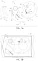
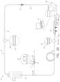
- FIGS. 1 A-Bshow a tube set that is for use with a pump, e.g., a medical pump, in accordance with some applications of the present invention
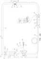
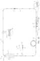
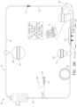
- FIGS. 2 A-Ware schematic illustrations that sequentially illustrate the tube set of FIGS. 1 A-B during use, in accordance with some applications of the present invention.
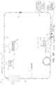
- FIG. 3is a graph showing experimental results for ten bubble detectors of a respective ten pumps, in accordance with some applications of the present invention.
- tube set 20that is for use with a pump, e.g., a medical pump as shown in FIG. 2 B , in accordance with some applications of the present invention.
- tube set 20comprises a reservoir 22 for holding a liquid, e.g., water.
- reservoir 22may be any standard enteral feeding bag.
- Tube set 20includes a tube 24 having an upstream end 26 and a downstream end 28 .
- the upstream and downstream ends of a tube segmentare defined such that when fluid is flowing through the tube segment, the fluid flows from the upstream end of the tube segment to the downstream end of the tube segment.
- both upstream end 26 and downstream end 28 of tube 24are coupled to reservoir 22 .
- a reservoir connector 30which couples, e.g., is inserted into, an exit spout 32 of reservoir 22 .
- a cap 34 of reservoir 22is coupled to tube 24 , such that when reservoir 22 is closed with cap 34 , downstream end 28 of tube 24 is disposed within reservoir 22 .
- cap 34may be a standard enteral feeding bag cap, with a hole drilled in the cap and tube 24 disposed through the hole.
- the calibration test performed using tube set 20may be performed consecutively for multiple pumps. Having downstream end 28 of tube 24 return the fluid to reservoir 22 enables (i) the setup to remain identical for each test performed and (ii) recirculating of the fluid. As each pump is tested, fluid advances through tube set 20 during the test and cycles back to the reservoir.
- cap 34 of reservoir 22is coupled to tube 24 prior to tube 24 being packaged for commercial sale, i.e., cap 34 is coupled to tube 24 in commercial packaging 25 .
- tube set 20is removed from commercial packaging 25 , e.g., by the technician who is testing the pumps, reservoir 22 is filled with liquid, e.g., water, upstream end 26 of tube 24 is coupled to reservoir 22 via reservoir connector 30 , and cap 34 used to close reservoir 22 , thereby coupling downstream end 28 of tube 24 to reservoir 22 .
- liquide.g., water
- Tube 24 of tube set 20typically has at least four tube segments.
- a first segment 36a second segment 38 downstream of first segment 36 , a third segment 40 downstream of second segment 38 , and a fourth segment 52 downstream of third segment 40 .
- first segment 36is coupled to reservoir 22 (e.g., via reservoir connector 30 as described hereinabove) such that liquid from reservoir 22 is received within first segment 36 through an upstream end 42 of first segment 36 .
- Tube 24is operatively coupled to a pump at a downstream end 44 of second segment 38 and at an upstream end 46 of third segment 40 .
- tube 24is operatively coupled to the pump via a tube cartridge 48 , through which is disposed a pump segment 50 of tube 24 , pump segment 50 of tube 24 being between second segment 38 and third segment 40 .
- Tube cartridge 48is coupled to tube 24 at a fixed location along tube 24 .
- Fourth segment 52typically leads back to reservoir 22 when tube set 20 is assembled, such that liquid 76 from fourth segment 52 is received within reservoir 22 through downstream end 54 of fourth segment 52 .
- Cap 34 of reservoir 22is typically coupled to fourth segment 52 of tube 24 at a downstream end 54 of fourth segment 52 .
- downstream end 28 of tube 24may not lead back to reservoir 22 , but rather may be set up to drain into an external receptacle as liquid is advanced through tube set 20 .
- An air port 56is coupled to tube 24 , typically via a connector 57 , e.g., a Y-connector or a T-connector, at downstream end 58 of first segment 36 and at upstream end 60 of second segment 38 , such that (a) first segment 36 of tube 24 is between reservoir 22 and air port 56 and (b) second segment 38 of tube 24 is between air port 56 and the pump when tube 24 is operatively coupled to the pump.
- a connector 57e.g., a Y-connector or a T-connector
- air port 56includes (i) a syringe 62 , (ii) a plunger 64 disposed within the barrel of syringe 62 , (iii) a first one-way valve 66 positioned so as to allow fluid, e.g., air, to flow from air port 56 into first segment 36 of tube 24 , and a second one-way valve 68 positioned so as to allow air from the external environment into air port 56 , i.e., into syringe 62 .
- air port 56facilitates insertion of an air bubble into tube 24 , i.e., into first segment 36 of tube 24 , as further described hereinbelow with reference to FIGS. 2 E-F .
- syringe 62is coupled to tube 24 while tube set 20 is disposed within commercial packaging 25 .
- a tube-occluding element 70e.g., a valve, is coupled to a downstream end 72 of third segment 40 and an upstream end 94 of fourth segment 52 .
- Tube-occluding element 70is used to reversibly occlude tube 24 , e.g., by toggling the valve between open and closed positions, or sliding a clamp on and off tube 24 .
- FIGS. 2 A-Ware schematic illustrations that sequentially illustrate tube set 20 in use, in accordance with some applications of the present invention.
- FIG. 2 Aschematically shows tube set 20 after being removed from packaging 25 , as it is being arranged for use.
- An external user interface device 74e.g., a processor, a computer, or handheld computing device, is typically connected to the pump being tested in order to receive information from the pump, e.g., a serial number unique to a given pump, and/or pump measurements, and to display information, e.g., instructions, and/or analysis of the pump measurements to the user.
- Reservoir 22is shown to be filled with liquid 76 , e.g., water, and cap 34 is coupled to reservoir 22 . As described hereinabove, typically there is a hole in cap 34 of reservoir 22 , through which downstream end 28 of tube 24 is disposed, and via which reservoir 22 is open to atmospheric pressure.
- dimensions of the various tube segmentsare selected such that (a) second segment 38 defines a predetermined volume of liquid between air port 56 and a pump when tube 24 is filled with liquid, (b) third segment of tube 24 is longer than first segment 36 , and (c) third segment 40 of tube 24 is shorter than second segment 38 .
- first one-way valve 66allows air 78 (such as is shown, for example, in FIGS. 2 E-F ) from within air port 56 to enter first segment 36 of tube 24 , i.e., first one-way valve 66 allows an air bubble 80 (such as is shown for example, in FIG. 2 F ) to be injected into first segment 36 .
- air 78is inserted into first segment 36 of tube 24 while pump 100 is off and thus blocking any fluid movement in the downstream direction.
- the aircan only rise upward toward reservoir 22 such that when first segment 36 is filled with air 78 , air bubble spans the length of first segment 36 , further described hereinbelow.
- tube set 20When tube set 20 is assembled, and tube 24 is operatively coupled to a pump air port 56 is typically disposed at a location that is at a height H of at least 0 cm and/or less than 100 cm above the pump, with respect to gravity. Additionally, when tube 24 is operatively coupled to a pump, second segment 38 of tube 24 is maintained between the height of the location above the pump and the pump, with respect to gravity, further described hereinbelow with reference to FIG. 2 G . (Thus, height H is defined irrespective of the length of tube in the coiled portion.)
- FIGS. 2 A-Killustrate sequential steps in a method for performing calibration tests of a pump 100 .
- FIG. 2 Ashows tube set 20 fully assembled after being removed from commercial packaging 25 , and after a user, e.g., a technician performing the tests, has filled reservoir 22 with liquid 76 .
- user interface device 74provides the user with step-by-step instructions, e.g., prompts, throughout the testing procedure, including, as further described hereinbelow, letting the user know if an error has occurred and that the test should be repeated.
- user interface device 74is shown to be giving an instruction to the user to operatively connect a pump to tube set 20 and to user interface device 74 .
- FIG. 2 Bshows a pump 100 , e.g., a first pump 100 a , operatively coupled to tube 24 via tube cartridge 48 .
- a bubble detector 102e.g., an optical bubble detector
- a sensor 104e.g., a force sensor
- Pump 100is also connected to user interface device 74 , e.g., a processor, a computer, or a handheld computing device.
- the pumpwhen the pump is connected to user interface device 74 , the pump automatically sends a unique identifier, e.g., a unique serial number, to user interface device 74 , such that the results of the calibration tests may be stored for that particular pump, and for some applications, sent to an external server.
- a unique identifiere.g., a unique serial number
- the useris prompted with instructions to fill tube 24 with liquid 76 from reservoir 22 , e.g., to prime tube 24 .
- this step of priming tube 24is only performed for first pump 100 a . For subsequent pumps connected to the same tube set 20 , tube 24 does not have to be primed again.
- FIG. 2 Cshows tube 24 being filled with liquid 76 .
- liquid 76is now disposed within and moving through tube 24 .
- pump 100is used to prime the set by being activated to pump liquid 76 from reservoir 22 .
- the usere.g., technician, may manually fill tube 24 with liquid 76 .
- pump 100is activated and pumps liquid 76 through tube 24 .
- Enlarged view circle 106shows liquid 76 now disposed within tube 24 and liquid-flow arrows 108 representing liquid 76 flowing through tube 24 .
- tube set 20when tube set 20 is filled with liquid 76 , the various segments and components of tube set 20 hold the following volumes of liquid:
- a volume of fluid that is larger than the full volume that tube set 20 can holde.g., 2 ml larger, is used in order to prime the set, so as to ensure that indeed the entire tube 24 is filled with liquid 76 .
- a volume of fluidthat is larger than the full volume that tube set 20 can hold, e.g., 2 ml larger, is used in order to prime the set, so as to ensure that indeed the entire tube 24 is filled with liquid 76 .
- a volume of fluid that is larger than the full volume that tube set 20 can holde.g., 2 ml larger, is used in order to prime the set, so as to ensure that indeed the entire tube 24 is filled with liquid 76 .
- tube set 20holds a total of 15.9 ml of liquid
- 17.9 ml of liquidis pumped using pump 100 in order to prime the set.
- Liquid droplets 110 in FIG. 2 Crepresent the excess fluid returning to reservoir 22 through downstream end 28 of tube 24 .
- FIG. 2 Dshows tube set 20 filled with liquid 76 .
- Pump 100is off, and user interface device 74 is prompting the user to fill syringe 62 with air, inject an air bubble into first segment of tube 24 , and confirm the injection of the air bubble, e.g., by pressing a suitable button on user interface device 74 .
- the systemidentifies this as an error during subsequent testing steps and will prompt the user to insert an air bubble and re-confirm in order to start the test again.
- Pump 100remains off until the user confirms that an air bubble has been injected into tube 24 .
- FIG. 2 Eshows syringe 62 filled with air 78 after the user has pulled plunger 64 .
- first one-way valve 66 and second one-way valve 68when the user pulls plunger 64 , only air 78 is allowed to flow into syringe 62 .
- tube 24is filled with liquid, however the liquid is not flowing due to pump 100 being off.
- Enlarged view circle 112shows air 78 disposed within syringe 62 .
- FIG. 2 Fshows the insertion of air bubble 80 , e.g., first air bubble 80 a , into first segment 36 of tube 24 .
- air bubble 80e.g., first air bubble 80 a
- FIG. 2 Fshows the insertion of air bubble 80 , e.g., first air bubble 80 a , into first segment 36 of tube 24 .
- first one-way valve 66 and second one-way valve 68when the user pushes plunger 64 into syringe 62 , air 78 from within syringe 62 is inserted into first segment 36 of tube 24 .
- syringe 62holds a larger volume of air than first segment 36 can hold.
- air bubble 80e.g., first air bubble 80 a
- first air bubble 80 atypically fills the entire length of first segment 36 , and thus has a length L 8 that is typically equal to length L 1 of first segment 36 .
- the insertion of air bubble 80 into tube 24does not increase pressure within tube 24 .
- the predetermined volume of liquidmay be 0.1 ml of liquid 76 within connector 57 plus 7.3 ml of liquid 76 in second segment 38 .
- FIG. 2 Gshows the test in progress after the user has confirmed the insertion of air bubble 80 .
- Pump 100is used to advance air bubble 80 along tube 24 , i.e., along second segment 38 of tube 24 , to bubble detector 102 of pump 100 .
- Enlarged view circle 106again shows liquid 76 flowing through tube 24
- enlarged view circle 118shows air 78 within air bubble 80 that is now advancing through second segment 38 .
- Using pump 100 to advance air bubble 80 along tube 24typically drives liquid 76 within tube 24 that is downstream of pump 100 to advance along tube 24 and subsequently exit tube 24 into reservoir 22 , as illustrated by liquid droplets 110 in FIG. 2 G .
- pump 100is used to measure, e.g., the pump automatically measures, the volume of liquid 76 that is pumped in order to advance air bubble 80 to bubble detector 102 .
- pump 100measures the volume of liquid 76 that is pumped to advance air bubble 80 to bubble detector 102 by assessing, e.g., counting, the number of pumping cycles during which pump 100 advances air bubble 80 to bubble detector 102 .
- Pump 100may assess, e.g., count, an integer number of pumping cycles of pump 100 as well as a non-integer number of pumping cycles of pump 100 . It is possible that when downstream end 116 of air bubble 80 reaches bubble detector 102 , pump 100 may be in the middle of a pumping cycle. Thus, in order for pump 100 to measure the volume pumped it must know exactly where in the current pumping cycle bubble detector 102 detected downstream end 116 of air bubble 80 .
- a DC motorthat comprises an indexed encoder is used to run pump 100 .
- bubble detector 102detects downstream end 116 of air bubble 80 , exactly which encoder the DC motor is at indicates to pump 100 where in the pumping cycle pump 100 is, which indicates the volume pumped up to that point in the pumping cycle.
- a parametere.g., accuracy of pump 100 , e.g., a level of pumping accuracy of pump 100 .
- the pumping accuracyis determined by a comparison between (i) the measured volume of liquid 76 pumped, e.g., as determined by the number of pump cycles counted by pump 100 , and (ii) the predetermined volume of liquid 76 between downstream end 116 of air bubble 80 and pump 100 , as defined by the dimensions of tube set 20 described hereinabove.
- determining the accuracy of pump 100includes determining a volume of liquid 76 that is pumped per pumping cycle of pump 100 .
- determining a volume of liquid 76 that is pumped per pumping cycle of pump 100includes determining a volume of liquid 76 that is pumped per pumping cycle of pump 100 .
- air bubble 80advances along a length of tube that is at least 20 cm and/or less than 200 cm, e.g., 99 cm, long.
- the inventorhas realized that if second segment 38 is too short, the results of the pumping accuracy determination may not be accurate. Thus, it is important for second segment 38 of tube 24 to be long enough in order for the results of the pumping accuracy determination to be accurate.
- air bubble 80may tend to float upwards while pump 100 is trying to advance it toward bubble detector 102 .
- air port 56 and pump 100are positioned such that pump 100 advances air bubble 80 from a location that is at height H above pump 100 with respect to the direction of gravity. Height H is at least 0 cm and/or less than 100 cm.
- second segment 38is typically relatively long, e.g., 99 cm, a portion 120 of second segment is typically coiled up, such that the entire length of second segment 38 is situated between air port 56 and pump 100 with respect to the direction of gravity.
- FIG. 2 Hshows downstream end 116 of air bubble 80 having reached bubble detector 102 .
- user interface device 74may display an indication to the user that downstream end 116 of air bubble 80 has been detected and the pump accuracy determined, as described hereinabove.
- liquid 76is still advancing through tube 24 , and pump 100 is on, i.e., after pump 100 advances air bubble 80 to bubble detector 102 , pump 100 continues to advance air bubble 80 along tube 24 without stopping, such that air bubble 80 advances past bubble detector 102 , e.g., past pump 100 , such as is shown in FIG. 2 I .
- FIG. 2 Ishows air bubble 80 after having advanced past bubble detector 102 of pump 100 .
- Pump 100e.g., bubble detector 102 of pump 100 , is used to measure the volume V 0 of air bubble 80 as air bubble 80 is advanced past bubble detector 102 .
- pump 100measures volume V 0 of air bubble 80 by assessing, e.g., counting, the number of pumping cycles of pump 100 during the advancing of air bubble 80 past bubble detector 102 of pump 100 .
- pump 100typically assesses the number of full and partial pumping cycles, e.g., using an indexed encoder as described above, to determine an exact volume of air bubble 80 .
- pump 100may measure the air 14 times during one pump cycle, which may create an inaccuracy of up to +/ ⁇ 2.5 microliters in the volume of the air bubble 80 . This is considered by the inventor to be a small and insignificant level of error.
- Liquid-flow arrows 108 in enlarged view circles 106 and 128show that pump 100 continues running after volume V 0 of air bubble 80 is measured, in order to advance air bubble 80 fully past pump 100 . If the user made an error when inserting air bubble 80 into tube 24 such that air bubble 80 is too small, e.g., less than 0.5 ml, after air bubble 80 is measured pump 100 will stop and the user will be asked to insert another air bubble and confirm in order to start the test again for that pump.
- FIG. 2 Jshows air bubble 80 after having advanced past pump 100 .
- pump 100has been on and pumping since the user confirmed the insertion of air bubble 80 .
- pump 100automatically stops after pumping a predetermined volume of liquid 76 so as to ensure that the entire air bubble 80 has passed pump segment 50 of tube 24 and is disposed within third segment 40 , i.e., upstream end 124 of air bubble 80 is downstream of pump 100 and downstream end 116 of air bubble is upstream of tube-occluding element 70 .
- pump 100may pump a volume equal to 0.1 ml in connector 57 +7.3 ml in second segment 38 , 0.8 ml in pump segment 50 +an extra delta of liquid 76 , e.g., 1 ml, that ensures an upstream end 124 of air bubble 80 is downstream of pump segment 50 , such as is shown in FIG. 2 J .
- No liquid-flow arrowsare shown in enlarged view circles 106 and 122 , due to pump 100 being off.
- third segment 40be longer than first segment 36 so as to ensure that the entirety of air bubble 80 is disposed within third segment 40 at this point in the test. Furthermore, it is possible that as air bubble 80 advances through tube 24 , the air bubble will split into a plurality of smaller air bubbles that may be spaced apart from each other by small volumes of liquid 76 . Thus, by the time air bubble 80 is past pump 100 , the length of tube between downstream end 116 of air bubble 80 and upstream end 124 of air bubble 80 may be longer than length L 1 of first segment 36 (where the air bubble was originally inserted). Thus, typically, length L 5 of third segment 40 (shown in FIG. 2 A ) is at least 20% and/or less than 50% longer than length L 1 of first segment 36 (shown in FIG. 2 A ) of first segment 36 .
- the system as described hereinaboveis generally immune to user errors having to do with insertion of air bubble 80 . If the user inserts too much air, the excess air simply exits tube 24 into reservoir 22 without any effect on the length of the air bubble, as described hereinabove. If the user, in error, forgot to insert air bubble 80 but confirmed the insertion of air bubble 80 , pump 100 will start to run as if to perform the first stage of the test, i.e., pumping accuracy determination. After pumping a predetermined volume of liquid 76 that is large enough such that downstream end 116 of air bubble 80 should have been detected by bubble detector 102 , pump 100 will stop and alert the user than an error has occurred.
- the userwill be given instructions to insert an air bubble and confirm in order to restart the test. If the user inserts air bubble 80 , but does not insert enough air, e.g., less than 0.5 ml, then when pump 100 measures volume V 0 of air bubble 80 , pump 100 will stop and alert the user than an error has occurred. The user will be given instructions to insert another air bubble and confirm in order to restart the test.
- the useris given instructions to occlude tube 24 downstream of air bubble 80 with tube-occluding element 70 , and to confirm the occlusion in order to move on to the calibration test of an occlusion sensor, e.g., force sensor 104 of pump 100 .
- an occlusion sensore.g., force sensor 104 of pump 100 .
- FIG. 2 Kshows pump 100 being used to increase pressure within tube 24 by pumping a volume of liquid 76 while tube 24 is occluded.
- Liquid 76 between downstream end 116 of air bubble 80 and tube-occluding element 70is not compressible, however air 78 within air bubble 80 is compressible.
- As pump 100 pumps the volume of liquidair bubble 80 is compressed by the volume of liquid pumped (Vp), thereby increasing pressure within tube 24 .
- Compressed air bubble 80has a length L 9 that is shorter than original length L 8 of air bubble 80 .
- pump 100pumps liquid 76 until pump 100 measures a preset pressure or more than one pressure stopping points are set and pump 100 measures each one of the preset pressure values (e.g., 0.4 bar, 0.8 bar, or 1.2 bar), at which point pump 100 stops.
- the volume pumped (Vp)is used together with the measured air bubble volume V 0 to calculate the expected pressure Pexp (P 1 in the equation below) upon compression of the air bubble.
- the expected pressureis then compared with the measured pressure value.
- V 0is the measured volume of air bubble 80 prior to being compressed
- V 1is the compressed volume of air bubble 80 , which is calculated based on the volume pumped (Vp) and the measured volume V 0 , and
- the occlusion sensor, e.g., force sensor, 104measures the increase dP (measured) in pressure within tube 24 .
- the calculated (expected) and measured pressuresare compared, and if the difference between them is within the tolerances of pump 100 then the test of the pressure sensor is considered to indicate proper functioning of pump 100 , and if not, a malfunction of pump 100 .
- pump 100pumps liquid 76 until pump 100 measures a volume pumped (Vp) that is equal to another value that is a percentage, e.g., 20%-60%, of volume V 0 of air bubble 80 .
- Vpmaxa maximum Vp (Vpmax) is typically set such that the pump stops if Vp>Vpmax, even if the expected pressure was not reached. This could potentially happen in a case where there are errors in V 0 or dP measurements.
- the expected increase in pressure of typically 0.5 baris compared to the sensed increase in pressure dP (measured), as measured by occlusion sensor, e.g., force sensor, 104 in response to pump 100 pumping volume Vp, in order to assess the accuracy of occlusion sensor, e.g., force sensor, 104 .
- occlusion sensore.g., force sensor
- Vppump 100 pumping volume
- Liquid-flow arrows 108illustrate that when pump 100 is on after tube 24 has been occluded, liquid 76 flows toward air bubble 80 , but there is no liquid flow downstream of air bubble 80 (due to the incompressible nature of the liquid). Thus, no liquid-flow arrows appear in third segment 40 downstream of air bubble 80 , and no liquid-flow arrows appear in fourth segment 52 .
- pump 100After pump 100 measures the sensed increase in pressure dP (measured) and compares it with the expected, calculated, increase in pressure, e.g., 0.4 bar, pump 100 continues to pump liquid 76 until a sensed pressure of at least 1.0 bar and/or less than 1.6 bar, e.g., 1.2 bar, is sensed. This verifies that pump 100 can generate a pressure equal to a maximum occlusion setting, and can detect it. The user is then prompted with instructions to remove the occlusion of tube 24 , e.g., to turn occlusion element 70 to an open position, or to remove a sliding clamp from tube 24 , and to change the pump that is operatively coupled to tube set 20 and user interface device 74 , such as is shown in FIG. 2 L .
- FIG. 2 Mshows tube set 20 after the occlusion of tube 24 has been released and first pump 100 a is no longer coupled to tube set 20 and user interface device 74 .
- air bubble 80i.e., first air bubble 80 a
- first air bubble 80 awill expand to its original volume.
- liquid 76 downstream of air bubble 80is pushed along tube 24 such that some liquid 76 from within fourth segment 52 enters reservoir 22 .
- air bubble 80is disposed between dashed lines 126 and 128 , and labeled with L 8 , indicating that air bubble 80 has expanded back to its original volume.
- FIG. 2 Nshows a second pump 100 b operatively coupled to tube 24 via tube cartridge 48 and to user interface device 74 .
- second pump 100 bwhen second pump 100 b is connected to user interface device 74 , second pump 100 b sends a unique identifier, e.g., a unique serial number, to user interface device 74 such that the results of the calibration tests may be stored for second pump 100 b .
- a unique identifiere.g., a unique serial number
- the same testing procedure that was performed for first pump 100 ais performed for second pump 100 b , and for subsequent pumps following second pump 100 b .
- the same tube set 20i.e., the same tube 24
- the same tube set 20may be used to test at least 10 and/or less than 50 pumps, e.g., 30 pumps, before tube 24 may start to degrade and affect the accuracy of the test results.
- a plurality of pumpsare tested, e.g., as a batch, and then the pumps that are determined to be in good working order are put back in use, while any pumps that are determined to not be in good working order may be sent for repair, e.g., back to the manufacturer.
- the next pumpis coupled to tube set 20 to be tested, without the first pump being used to administer anything to a patient prior to the next pump being tested.
- FIG. 2 Oshows syringe 62 again filled with air 78 after the user has pulled plunger 64 .
- first air bubble 80 ais still disposed within third segment 40 , as illustrated by enlarged view circle showing air 78 of first air bubble 80 , which is disposed between dashed lines 126 and 128 .
- the testing stepsare repeated for pump 100 b without the user, e.g., technician, having to prime tube set 20 again. That is, after tube set 20 is primed, i.e., filled with liquid for the testing of first pump 100 a , tube set 20 does not have to be primed again.
- the techniciantypically uses a second tube set 20 , and primes second tube set 20 prior to testing a first pump 100 a for that tube set.
- FIG. 2 Pshows the insertion of second air bubble 80 b into first segment 36 of tube 24 . Due to reservoir 22 being open to the atmosphere, the insertion of second air bubble 80 a is also without increasing pressure within tube 24 , and additionally does not cause any movement in liquid 76 that is disposed downstream of air port 56 , as illustrated by lack of liquid-flow arrows in tube 24 . Air-flow arrows 79 in first segment 36 illustrate air 78 rising toward reservoir 22 as second air bubble 80 b fills first segment 36 .
- FIG. 2 Qshows the test in progress after the user has confirmed the insertion of second air bubble 80 b .
- second pump 100 bis used to advance second air bubble 80 b to bubble detector 102 b of second pump 100 b
- first air bubble 80 aadvances along tube 24 as well.
- Enlarged view circle 132shows air 78 of second air bubble 80 b as it advances through second segment 38
- enlarged view circle 134shows air 78 of first air bubble 80 a as it simultaneously advances along third segment 40 .
- the respective volumes of both air bubblesare approximately the same at this point in the process.
- FIG. 2 Rshows downstream end 116 of second air bubble 80 b having reached bubble detector 102 b of second pump 100 b , such that a parameter, e.g., accuracy, e.g., level of pumping accuracy, of second pump 100 b is determined, as described hereinabove with reference to the first pump.
- a parametere.g., accuracy, e.g., level of pumping accuracy
- third segment 40is shorter than second segment 38 , such that as the volume of liquid held in second segment 38 is pumped in order to advance second air bubble 80 b to bubble detector 102 b of second pump 100 b , first air bubble 80 a advances by the same volume, and thus necessarily will be disposed downstream of tube-occluding element 70 , within fourth segment 52 , by the time downstream end 116 of second air bubble 80 b is detected by bubble detector 102 .
- length L 2 (shown in FIG. 2 A ) of second segment 38is at least 20% and/or less than 80% longer than length L 5 (shown in FIG. 2 A ) of third segment 40 .
- first air bubble 80 ais shown disposed within fourth segment 52 , as illustrated by air 78 shown in enlarged view circle 138 and length L 8 of first air bubble 80 a .
- first air bubble 80 atypically exits tube 24 into reservoir 22 .
- FIG. 2 Sshows second air bubble 80 b having advanced past bubble detector 102 b of second pump 100 b .
- first air bubble 80 bmay have exited tube 24 into reservoir 22 , and as such first air bubble 80 a is not shown within tube 24 in FIG. 2 S .
- first air bubble 80 amay still be disposed within fourth segment 52 , however since first air bubble 80 a is necessarily entirely downstream of tube-occluding element 70 , its presence within tube 24 is irrelevant to calibration tests being performed on second pump 100 b .
- the volume V 0 of second air bubble 80 bis measured and the occlusion sensor, e.g., force sensor, 104 b test is carried out for second pump 100 b , as described hereinabove with reference to the first pump.
- FIG. 2 Tshows second air bubble 80 b disposed within third segment 40 , and the user receives instructions to occlude tube 24 and confirm.
- FIG. 2 Ushows second air bubble 80 a being compressed as second pump 100 b is used to increase pressure within tube 24 in order to test the accuracy of occlusion sensor, e.g., force sensor, 104 b of second pump 100 b , as described hereinabove with reference to the first pump.
- FIG. 2 Vshows tube set 20 after the test of second pump 100 b are complete, and the user again receives instructions to remove the occlusion of tube 24 and connect a next pump.
- FIG. 2 Wshows tube set 20 ready for the next pump to be connected.
- bubble detector 102has (a) a pump-specific liquid-signal, e.g., an analog-to-digital (A/D) signal of a specific value, when that bubble detector detects liquid, and (b) a pump-specific air signal, e.g., an A/D signal of a specific value, when that bubble detector detects air.
- a pump-specific liquid-signale.g., an analog-to-digital (A/D) signal of a specific value
- A/Danalog-to-digital
- a pump-specific air signale.g., an A/D signal of a specific value
- the bubble detector 102 of a pump 100is in good working condition, e.g., is properly calibrated, then, while the pump 100 is in use, (a) the values of the liquid-signals, e.g., A/D liquid-signals, generated by the bubble detector 102 when liquid is passing the bubble detector 102 should typically fall within a predetermined range of values that is typically within a delta of +/ ⁇ 30 from the value of the pump-specific liquid-signal for that pump 100 , and (b) the values of the air-signals, e.g., A/D air-signals, generated by the bubble detector 102 when air is passing the bubble detector 102 should typically fall within a predetermined range of values that is typically within a delta of +/ ⁇ 20 from the pump-specific air signal for that pump 100 .
- the values of the liquid-signalse.g., A/D liquid-signals
- the air-signalse.g., A/D air-signals
- the larger empty circles 144 in FIG. 3represent measured values of respective liquid-signals, e.g., A/D liquid signals, generated in response to each of the 10 bubble detectors detecting liquid 76 within tube 24 .
- the larger empty squares 146represent measured values of respective air-signals, e.g., A/D air-signals, generated in response to each of the ten bubble detectors detecting air 78 within tube 24 .
- a plurality of experimentswere performed for each of the ten pumps. For each experiment there is shown a corresponding larger empty circle 144 and larger empty square 146 , representing the measured values of the respective A/D liquid-signal and A/D air signal measure for that particular experiment with that pump.
- the inventorhas realized that it is highly unlikely for a bubble detector 102 that is not in working order, e.g., not properly calibrated, to “accidentally” generate a signal that is within the expected predetermined range.
- a bubble detector 102that is not in working order, e.g., not properly calibrated, to “accidentally” generate a signal that is within the expected predetermined range.
- data point 152 in FIG. 3if a given bubble detector 102 generates a liquid-signal having a value that is within the respective predetermined range, but generates an air-signal having a value that is not within the respective predetermined range, it can still be assumed that the bubble detector is in working order, and that likely an unrelated circumstance caused the air-signal to be out of range.
- data points 148 and 150 in FIG. 3i.e., if a given bubble detector generates an air-signal having a value that is within range, but a liquid-signal that is out of range, it can still be assumed that the
- Data point 148represents the value of an A/D air-signal for one of the experiments performed using the pump # 1 in the experiment. As shown, data point 148 is out of range, i.e., the difference between (a) the A/D air-signal measured for data point 148 and (b) the pump-specific A/D air-signal for the pump # 1 , is greater than a chosen delta (e.g., a delta of 20).
- a chosen deltae.g., a delta of 20.
- the corresponding data point 156representing the A/D liquid-signal measured in the same experiment with pump # 1 is within range, i.e., the difference between (a) the A/D liquid-signal measured for data point 156 and (b) the pump-specific A/D liquid-signal for the pump # 1 , is less than a chosen delta (e.g., a delta of 30).
- a chosen deltae.g., a delta of 30
- data point 150representing the value of an A/D air-signal measured during an experiment with pump # 2 , is out of range, i.e., the difference between (a) the A/D air-signal measured for data point 150 and (b) the pump-specific A/D air-signal for the pump # 2 , is greater than a chosen delta (e.g., a delta of 20).
- a chosen deltae.g., a delta of 20
- the corresponding data point 160representing the value of an A/D liquid-signal measured during the same experiment with pump # 2 , is within range, i.e., the difference between (a) the A/D liquid-signal measured for data point 160 and (b) the pump-specific A/D liquid-signal for the pump # 2 , is less than a chosen delta (e.g., a delta of 30).
- a chosen deltae.g., a delta of 30
- data point 152representing the value of an A/D liquid-signal measured during an experiment with pump # 8 , is out of range, i.e., the difference between (a) the A/D liquid-signal measured for data point 152 and (b) the pump-specific A/D liquid-signal for the pump # 8 , is greater than a chosen delta (e.g., a delta of 30).
- a chosen deltae.g., a delta of 30
- the corresponding data point 164representing the A/D air-signal measured in the same experiment with pump # 8 , is within range, i.e., the difference between (a) the A/D air-signal measured for data point 164 and (b) the pump-specific A/D air-signal for the pump # 8 , is less than a chosen delta (e.g., a delta of 20).
- a chosen deltae.g., a delta of 20
- a parameter of bubble detector 102may be determined by measuring respective values of (a) the liquid-signals generated by bubble detector 102 as liquid 76 is passing bubble detector 102 and (b) the air-signals generated by bubble detector 102 when air bubble 80 is passing bubble detector 102 . If at least one of the two signals, i.e., if the generated liquid-signal or the generated air-signal, is within the respective predetermined range of values, then a determination may be made that bubble detector 102 is in working order, e.g., is properly calibrated.
- bubble detector 102may be determined to be in working order already before air bubble 80 is detected by bubble detector 102 if the values of the generated liquid-signals, e.g., A/D liquid-signals generated by bubble detector 102 in response to liquid 76 advancing past bubble detector 102 are within the respective predetermined range.
- the values of the generated liquid-signalse.g., A/D liquid-signals generated by bubble detector 102 in response to liquid 76 advancing past bubble detector 102 are within the respective predetermined range.
- the values of the generated liquid-signalse.g., A/D liquid-signals
- a determinationmay be made after measuring the value of the air signals, e.g., generated in response to bubble detector 102 detecting air bubble 80 . If the generated air-signal, e.g., A/D air signal, is within the respective predetermined range, then bubble detector 102 is considered to be in good working order.
- bubble detector 102is determined to not be working properly, and the test is stopped. Typically, the user will be instructed at that point to remove the pump and start testing the next pump.
- a pump 100 or a component, e.g., sensor, of pump 100is determined to not be in working order, the test is immediately stopped and the user asked to move on to the next pump.
- the entire test of first pump 100 atakes approximately a minute and a half, and the entire test of subsequent pumps (for which tube set 20 does not have to be primed) takes about approximately a minute.
- a computer-usable or computer-readable mediumcan be any apparatus that can comprise, store, communicate, propagate, or transport the program for use by or in connection with the instruction execution system, apparatus, or device.
- the mediumcan be an electronic, magnetic, optical, electromagnetic, infrared, or semiconductor system (or apparatus or device) or a propagation medium.
- the computer-usable or computer readable mediumis a non-transitory computer-usable or computer readable medium.
- Examples of a computer-readable mediuminclude a semiconductor or solid-state memory, a random-access memory (RAM), a read-only memory (ROM).
- RAMrandom-access memory
- ROMread-only memory
- cloud storage, and/or storage in a remote serveris used.
- a data processing system suitable for storing and/or executing program codewill include at least one processor (e.g., a processor of user interface device 74 ) coupled directly or indirectly to memory elements through a system bus.
- the memory elementscan include local memory employed during actual execution of the program code, bulk storage, and cache memories which provide temporary storage of at least some program code in order to reduce the number of times code must be retrieved from bulk storage during execution.
- the systemcan read the inventive instructions on the program storage devices and follow these instructions to execute the methodology of the embodiments of the invention.
- Network adaptersmay be coupled to the processor to enable the processor to become coupled to other processors or remote printers or storage devices through intervening private or public networks.
- Modems, cable modem and Ethernet cardsare just a few of the currently available types of network adapters.
- Computer program code for carrying out operations of some applications of the present inventionmay be written in any combination of one or more programming languages, including an object-oriented programming language such as Java, Smalltalk, C++ or the like and conventional procedural programming languages, such as the C programming language or similar programming languages.
- object-oriented programming languagesuch as Java, Smalltalk, C++ or the like
- conventional procedural programming languagessuch as the C programming language or similar programming languages.
- These computer program instructionsmay also be stored in a computer-readable medium (e.g., a non-transitory computer-readable medium) that can direct a computer or other programmable data processing apparatus to function in a particular manner, such that the instructions stored in the computer-readable medium produce an article of manufacture including instruction means which implement the function/act specified in the methods described in the present application.
- the computer program instructionsmay also be loaded onto a computer or other programmable data processing apparatus to cause a series of operational steps to be performed on the computer or other programmable apparatus to produce a computer implemented process such that the instructions which execute on the computer or other programmable apparatus provide processes for implementing the functions/acts specified in the methods described in the present application.
- User interface device 74is typically a hardware device programmed with computer program instructions to produce a special purpose computer.
- the computer processorwhen programmed to perform the methods described herein, the computer processor typically acts as a special purpose computer processor.
- the operations described herein that are performed by computer processorstransform the physical state of a memory, which is a real physical article, to have a different magnetic polarity, electrical charge, or the like depending on the technology of the memory that is used.
Landscapes
- Health & Medical Sciences (AREA)
- Heart & Thoracic Surgery (AREA)
- Vascular Medicine (AREA)
- Life Sciences & Earth Sciences (AREA)
- Public Health (AREA)
- Engineering & Computer Science (AREA)
- Anesthesiology (AREA)
- Biomedical Technology (AREA)
- Veterinary Medicine (AREA)
- Animal Behavior & Ethology (AREA)
- Hematology (AREA)
- General Health & Medical Sciences (AREA)
- General Physics & Mathematics (AREA)
- Fluid Mechanics (AREA)
- Physics & Mathematics (AREA)
- Cardiology (AREA)
- Emergency Medicine (AREA)
- Infusion, Injection, And Reservoir Apparatuses (AREA)
Abstract
Description
The present application claims the priority of U.S. 62/936,941 to Eitan, filed Nov. 18, 2019, entitled “Fast test for medical pump,” which is incorporated herein by reference.
The present invention relates generally to medical fluid-delivery devices, and more specifically to calibration testing of medical fluid-delivery pumps.
Pumps are often used in the medical industry for delivering fluids, e.g., drugs, or diagnostic fluids, to subjects. It is important that medical pumps be calibrated properly so as to ensure that subjects receiving fluid from such pumps are receiving the correct dosages at the correct flow rates, and that safety features of a pump, such as for example, occlusion detection, are properly working. Thus, medical pumps being used in the field, e.g., in a hospital setting, doctor's office, medical treatment center, or a subject's home, typically undergo periodic calibration testing in order to check for pumps that may need to be recalibrated and/or fixed prior to being put back into use. Typically, such calibration testing is done at an off-site lab by a technician.
U.S. Pat. No. 9,726,167 to Schweitzer describes an infusion pump which may include a native pumping mechanism to drive fluids through a functionally associated conduit, at least one native sensor to sense a physical characteristic of the fluid within the conduit, and computing circuitry having a decalibration test mode to determine whether the infusion pump is decalibrated. The computing circuitry may be adapted to receive output from at least one native sensor during the decalibration test mode. Other embodiments are also described.
Apparatus and methods are provided for periodically testing a pump, e.g., a medical pump, in order to determine (a) a parameter of the pump, e.g., a level of pumping accuracy of the pump, or the volume of liquid pumped per pumping cycle of the pump, and/or (b) a level of accuracy of a sensor of the pump, e.g., a force sensor of the pump, and/or a bubble detector of the pump.
In accordance with some applications of the present invention, a method is provided for determining a parameter of a pump based on using the pump to pump a predetermined, known, volume of liquid while the pump simultaneously measures the volume of liquid being pumped. The measured volume of liquid pumped may then be compared to the known volume of liquid pumped in order to determine a parameter of the pump, e.g., in order to assess the pumping accuracy of the pump, e.g., whether the pump is pumping the correct volume of fluid per pumping cycle. After placing liquid into a tube set that is coupled to a pump, an air bubble is injected into the tube such that there is a predetermined, known, volume of liquid between the air bubble and the pump. The pump is then activated so as to advance the air bubble to the bubble detector of the pump. While the pump is pumping, the pump automatically measures the volume of liquid that is being pumped, such that when a downstream edge of the bubble is detected by the bubble detector, the entirety of the predetermined volume of fluid has been pumped and the known volume of liquid pumped may be compared with the volume of liquid as measured by the pump in order to determine a parameter of the pump, e.g., a level of pumping accuracy of the pump.
In accordance with some applications of the present invention, a method is provided for determining a level of accuracy of a sensor, e.g., a force sensor, of a pump. After placing liquid into a tube set that is coupled to a pump, an air bubble is injected into the tube, the pump is activated so as to advance the air bubble past a bubble detector of the pump, while simultaneously measuring the volume of the air bubble. The tube is then occluded downstream of the air bubble and the pump is used to further pump a volume of liquid so as to compress the air bubble. Based on knowing the measured volume of the bubble and the volume of liquid pumped in order to compress the bubble, an expected increase in pressure in the tube is assessed, e.g., calculated. A sensor of the pump, e.g., a force sensor, measures the increase in force in the tube due to the compression of the air bubble, and the expected increase in force may be compared to the measured increase in force in order to determine a level of accuracy of the sensor.
In accordance with some applications of the present invention, a method is provided for determining a parameter of a bubble detector of a pump, e.g., an optical bubble detector. For any given pump, the bubble detector has (a) a pump-specific liquid-signal, e.g., an analog-to-digital (A/D) signal of a specific value, when the bubble detector detects liquid, and (b) a pump-specific air signal, e.g., an A/D signal of a specific value, when the bubble detector detects air. If the bubble detector of a pump is in good working condition, e.g., is properly calibrated, then, while the pump is in use, (a) the values of the liquid-signals generated by the bubble detector when liquid is passing the bubble detector should typically fall within a predetermined range of values that is typically within a delta of +/−30 from the pump-specific liquid-signal, e.g., 30 out of 1024 for a 10-bit A/D signal, and (b) the values of the air-signals generated by the bubble detector when air is passing the bubble detector should typically fall within a predetermined range of values that is typically within a delta of +/−20 from the pump-specific air signal, e.g., 20 out of 1024 for a 10-bit A/D signal.
The inventor has realized that if a bubble detector that is in good working condition, e.g., is properly calibrated, happens to generate a signal (either a liquid-signal or an air-signal) that is outside of the respective expected predetermined range, that signal can be ignored as it is likely not due to a problem with the sensor, but rather a measurement error (e.g., a data transfer error). Correspondingly, it is highly unlikely for a bubble detector that is not in working order, e.g., not properly calibrated, to “accidentally” generate a signal that is within the expected predetermined range. Thus, for example, if a given bubble detector generates a liquid-signal having a value that is within the respective predetermined range, but generates an air-signal having a value that is not within the respective predetermined range, it can still be assumed that the bubble detector is in working order, and that likely an unrelated circumstance caused the air-signal to be out of range. The same is true vice versa, i.e., if a given bubble detector generates an air-signal having a value that is within range, but a liquid-signal that is out of range, it can still be assumed that the bubble detector is in working order. This assumption is further substantiated by the successful completion of the rest of the test, further described hereinbelow, as the measurement of the air bubble size and the calculated pressure all depend on the bubble detector being in good working order.
After placing liquid into a tube set that is coupled to a pump, an air bubble is injected into the tube, and the pump is used to advance the air bubble to and past the bubble detector of the pump. A parameter of the bubble detector may be determined by measuring respective values of the liquid-signals generated by the bubble detector as the liquid is passing the bubble detector and air-signals generated by the bubble detector when the bubble is passing the bubble detector. If at least one of the two signals, i.e., if the generated liquid-signal or the generated air-signal, is within the respective predetermined range of values, then a determination may be made that the bubble detector is in working order, e.g., is properly calibrated.
In accordance with some applications of the present invention, a specialized tube set is provided for carrying out the various tests, which are typically carried out in succession, as further described hereinbelow. The tube set includes (a) a reservoir for holding the liquid, e.g., water, (b) an air port for insertion of air into the tube and (c) a tube cartridge for operatively coupling the tube to a pump at a specific location along the tube, such that there is a predetermined distance (which translates to a predetermined volume of liquid when the tube is filled with liquid) between the air port and the pump when the tube set is coupled to a pump, and (d) a tube-occluding element coupled to the tube downstream of the tube cartridge for occluding liquid flow within the tube. Thus, when the air bubble is injected into the tube, there is a predetermined volume of liquid between the air bubble and the pump.
An air bubble may be injected into the tube and the pump may be used to pump the predetermined volume of liquid between the air bubble and the pump, while simultaneously measuring the volume of the liquid being pumped. When the pump detects the air bubble, as described hereinabove, the known volume of liquid pumped is compared to the measured volume in order to determine a parameter of the pump. The pump is then used to continue advancing the same air bubble past the pump in order to measure a volume of the air bubble. After the air bubble is past the pump, the tube is occluded downstream of the air bubble and the pump is used to pump a further volume of liquid so as to compress the air bubble. As described hereinabove, a sensor of the pump, e.g., a force sensor, measures the increase in force in the tube due to the compression of the air bubble, and an expected increase in force may be compared to the measured increase in force in order to determine a level of accuracy of the sensor. At any point during the advancing of the air bubble through the tube set, liquid-signals and air-signals generated by the bubble detector are measured in order to determine a parameter of the bubble detector. Thus, by moving a single air bubble through the tube set, all three of the abovementioned calibration tests may be performed for a given pump.
Dimensions of the tube set are typically set such that the length of the tube segment that is disposed between the pump and the tube-occluding element is longer than the length of the tube segment that is between the air port and the reservoir. When the air bubble is injected into the tube, the length of the air bubble typically spans the entire length of tube between the air port and the reservoir. The length of the tube segment between the pump and occluding element being longer than the length of the tube segment between the air port and the reservoir allows for the pump to be able to advance the entirety of the air bubble past the pump while the tube-occluding element remains downstream of the air bubble.
Additionally, dimensions of the tube set are typically set such that the length of tube segment that is disposed between the pump and the tube-occluding element is shorter than the length of the tube segment between the air port and the pump. After a given pump is coupled to the tube segment and the abovementioned tests performed, the pump may be disconnected from the tube set and another pump coupled to the tube set in its place. The air bubble, following having been used in performing the tests on the first pump, is typically still in the tube set, between the pump and the tube-occluding element. The length of the tube segment between the pump and the tube-occluding element being shorter than the length of the tube segment between the air port and the pump ensures that as a second bubble is advanced from the air port to the pump, the entirety of the first air bubble that was disposed between the pump and the tube-occluding element will have advanced past the occluding element. Thus, the first air bubble remains within the tube set during the testing of the next pump, yet the first air bubble has no effect on the tests being performed on the next pump—it will simply advance through the tube set as the next pump is tested, typically making its way back to the reservoir where it exits the tube.
There is therefore provided, in accordance with some applications of the present invention, a method for use with a pump, the method including:
placing liquid in a tube that is coupled to the pump;
creating an air bubble in the tube by injecting air into the tube in a manner that does not increase pressure within the tube;
using the pump to measure a volume of the air bubble;
subsequently, occluding the tube downstream of the air bubble;
using the pump, increasing pressure within the tube by pumping a volume of liquid;
using the pump to measure the volume of liquid pumped;
assessing the increase in pressure within the tube based on the measured volume of liquid pumped and the measured volume of the air bubble;
using a sensor of the pump, measuring a sensed increase in pressure in the tube in response to the pumping of the volume of liquid; and
based on (i) the assessed increase in pressure and (ii) the sensed increase in pressure, determining a level of accuracy of the sensor.
For some applications, injecting the air into the tube includes injecting the air into the tube at a location that is upstream of the pump.
For some applications, occluding the tube downstream of the air bubble includes occluding the tube downstream of the pump.
For some applications, using the pump to measure the volume of the air bubble includes using the pump to advance the air bubble to, and past, a bubble detector of the pump.
For some applications, using the pump to measure the volume of the air bubble includes assessing the number of pumping cycles of the pump during the advancing of the air bubble past the bubble detector.
For some applications, assessing includes counting an integer number of pumping cycles of the pump.
For some applications, assessing includes assessing a non-integer number of pumping cycles of the pump.
There is further provided, in accordance with some applications of the present invention, a method for use with a pump, the method including:
placing liquid in a tube that is coupled to the pump;
creating an air bubble in the tube by injecting air into the tube in a manner that does not increase pressure within the tube, such that there is a predetermined volume of liquid between the air bubble and the pump;
using the pump to advance the air bubble along the tube to the bubble detector;
using the pump, measuring the volume of liquid pumped to advance the air bubble to the bubble detector; and
determining a parameter of the pump based on the measured volume.
For some applications, measuring the volume of liquid pumped to advance the air bubble to the bubble detector includes assessing the number of pumping cycles during which the pump advances the air bubble to the bubble detector.
For some applications, assessing includes counting an integer number of pumping cycles of the pump.
For some applications, assessing includes assessing a non-integer number of pumping cycles of the pump.
For some applications, determining the parameter of the pump includes determining a level of pumping accuracy of the pump.
For some applications, determining the parameter of the pump includes determining a volume of the liquid that is pumped per pumping cycle of the pump.
For some applications, the method further includes:
measuring a value of an air-signal generated by the bubble detector in response to the bubble detector detecting the air bubble; and
determining if a value of the air-signal is within a predetermined range of values for detection of an air bubble.
For some applications, measuring the value of the air-signal includes measuring the value of an analog-to-digital (A/D) air signal generated by the bubble detector in response to the bubble detector detecting the air bubble.
For some applications, the method further includes:
measuring a value of a liquid-signal generated by the bubble detector in response to the bubble detector detecting the liquid in the tube; and
determining if a value of the liquid-signal is within a predetermined range of values for detection of liquid.
For some applications, measuring the value of the liquid-signal includes measuring the value of an analog-to-digital (A/D) liquid signal generated by the bubble detector in response to the bubble detector detecting the liquid in the tube.
For some applications, the method further includes:
measuring a value of an air-signal generated by the bubble detector in response to the bubble detector detecting the air bubble; and
determining if a value of the air-signal is within a predetermined range of values for detection of an air bubble.
For some applications, measuring the value of the air-signal includes measuring the value of an analog-to-digital (A/D) air signal generated by the bubble detector in response to the bubble detector detecting the air bubble.
For some applications, using the pump to advance the air bubble along the tube to the bubble detector includes using the pump to advance the air bubble through a length of the tube that is 20-200 cm long.
For some applications, using the pump to advance the air bubble along the tube to the bubble detector includes using the pump to advance the air bubble from a location that is at a height of 0-100 cm above the pump, with respect to the direction of gravity.
For some applications, using the pump to advance the air bubble to the pump includes maintaining the air bubble between the height of the location above the pump and the pump, with respect to gravity during the advancing.
There is further provided, in accordance with some applications of the present invention, a method for use with a pump, the method including:
placing liquid in a tube that is coupled to the pump;
creating an air bubble in the tube by injecting air into the tube;
using the pump to advance the air bubble along the tube to a bubble detector of the pump;
measuring:
- (a) a value of a liquid-signal generated by the bubble detector in response to the bubble detector detecting the liquid within the tube, and
- (b) a value of an air-signal generated by the bubble detector in response to the bubble detector detecting the air bubble within the tube;
determining if at least one of the measured values is within a respective predetermined range of values; and
determining a parameter of the bubble detector based on the determination.
For some applications, (a) measuring the value of the liquid signal includes measuring the value of an analog-to-digital (A/D) liquid-signal generated by the bubble detector in response to the bubble detector detecting the liquid within the tube, and (b) measuring the value of the air signal includes measuring the value of an A/D air-signal generated by the bubble detector in response to the bubble detector detecting the air bubble within the tube.
There is further provided, in accordance with some applications of the present invention, a method for use with a pump, the method including:
- (A) placing liquid in a tube that is coupled to the pump;
- (B) creating an air bubble in the tube by injecting air into the tube (a) in a manner that does not increase pressure within the tube, and (b) such that there is a predetermined volume of liquid between the air bubble and the pump;
- (C) using the pump to advance the air bubble along the tube to the bubble detector of the pump;
- (D) using the pump, assessing accuracy of the pump by automatically measuring the volume of liquid pumped to advance the air bubble to the bubble detector; and
- (E) using the pump to continue advancing the air bubble along the tube, past the bubble detector, and using the pump to measure a volume of the air bubble.
For some applications, automatically measuring the volume of liquid pumped to advance the air bubble to the bubble detector includes automatically assessing the number of pumping cycles during which the pump advances the air bubble to the bubble detector.
For some applications, assessing includes counting an integer number of pumping cycles of the pump.
For some applications, assessing includes assessing a non-integer number of pumping cycles of the pump.
For some applications, assessing accuracy of the pump includes determining a level of pumping accuracy of the pump.
For some applications, assessing accuracy of the pump includes determining a volume of the liquid that is pumped per pumping cycle of the pump.
For some applications, using the pump to advance the air bubble along the tube includes driving the liquid within the tube that is downstream of the pump to advance along the tube and subsequently exit the tube into a reservoir from which the pump is operatively coupled to pump the liquid.
For some applications, using the pump to continue advancing the air bubble along the tube, past the bubble detector, includes using the pump to continue advancing the air bubble along the tube, past the pump.
For some applications, using the pump to measure the volume of the air bubble includes using the bubble detector of the pump to measure the volume of the air bubble.
For some applications, using the pump to measure the volume of the air bubble includes assessing the number of pumping cycles of the pump during the advancing of the air bubble past the bubble detector of the pump.
For some applications, assessing includes counting an integer number of pumping cycles of the pump.
For some applications, assessing includes assessing a non-integer number of pumping cycles of the pump.
For some applications, the method further includes: measuring a value of an air-signal generated by the bubble detector in response to the bubble detector detecting the air bubble; and
determining if a value of the air-signal is within a predetermined range of values for detection of an air bubble.
For some applications, measuring the value of the air-signal includes measuring the value of an analog-to-digital (A/D) air signal generated by the bubble detector in response to the bubble detector detecting the air bubble.
For some applications, the method further includes:
measuring a value of a liquid-signal generated by the bubble detector in response to the bubble detector detecting the liquid within the tube; and
determining if a value of the liquid-signal is within a predetermined range of values for the detection of liquid.
For some applications, measuring the value of the liquid-signal includes measuring the value of an analog-to-digital (A/D) liquid signal generated by the bubble detector in response to the bubble detector detecting the liquid in the tube.
For some applications, the method further includes:
measuring a value of an air-signal generated by the bubble detector in response to the bubble detector detecting the air bubble; and
determining if a value of the air-signal is within a predetermined range of values for detection of an air bubble.
For some applications, measuring the value of the air-signal includes measuring the value of an analog-to-digital (A/D) air signal generated by the bubble detector in response to the bubble detector detecting the air bubble.
For some applications, injecting the air into the tube includes injecting the air into the tube at a location that is upstream of the pump.
For some applications, the method further includes:
- (F) subsequently, occluding the tube downstream of the air bubble,
- (G) using the pump to increase pressure within the tube by pumping a volume of liquid,
- (H) using the pump to measure the volume of liquid pumped to increase pressure within the tube;
- (I) assessing the increase in pressure within the tube based on (a) the measured volume of liquid pumped to increase the pressure within the tube and (b) the measured volume of the air bubble;
- (J) using a sensor of the pump, measuring a sensed increase in pressure in the tube in response to the pumping of the volume of liquid; and
- (K) assessing accuracy of the sensor based on the assessed increase in pressure and the sensed increase in pressure.
For some applications, occluding the tube downstream of the air bubble includes occluding the tube downstream of the pump.
For some applications, the pump is a first pump, and wherein the method further includes, subsequently to step (K):
(i) removing the occlusion of the tube,
(ii) disconnecting the first pump from the tube;
(iii) coupling a second pump to the tube; and
(iv) repeating steps (B) through (K) using the second pump.
For some applications, repeating steps (B) through (K) using the second pump includes repeating steps (B) through (K) without repeating step (A) prior to the repeating of steps (B) through (K).
For some applications, repeating steps (B) through (K) using the second pump includes repeating steps (B) through (K) without using the first pump to administer anything to a patient (i) following the completion of step (K) using the first pump and (ii) prior to the coupling of the second pump to the tube.
For some applications, repeating steps (B) through (K) includes using the same tube to repeat steps (B) through (K) 10-50 times using a respective pump each time.
For some applications, the air bubble created in step (B) using the first pump is a first air bubble, and wherein repeating step (B) using the second pump includes creating a second air bubble in the tube while the first air bubble remains within the tube at a location that is downstream of the pump.
For some applications, repeating steps (B) through (E) using the second pump includes driving the first air bubble to advance along the tube, such that repeating step (F) using the second pump comprises occluding the tube downstream of the second air bubble and not downstream of any part of the first air bubble.
For some applications, repeating steps (B) through (E) using the second pump includes driving the first air bubble to advance along the tube and subsequently exit the tube into a reservoir from which the pump is operatively coupled to pump the liquid.
For some applications, using the pump to advance the air bubble along the tube to the bubble detector includes using the pump to advance the air bubble through a length of tube that is 20-200 cm long.
For some applications, using the pump to advance the air bubble along the tube to the bubble detector includes using the pump to advance the air bubble from a location that is at a height of 0-100 cm above the pump, with respect to the direction of gravity.
For some applications, using the pump to advance the air bubble to the pump includes maintaining the air bubble between the height of the location above the pump and the pump, with respect to gravity during the advancing.
There is further provided, in accordance with some applications of the present invention, apparatus for use with a pump, the apparatus including:
a reservoir configured to hold a liquid;
a tube having a first segment, a second segment downstream of the first segment, and a third segment downstream of the second segment, the first segment coupled to the reservoir such that liquid from the reservoir is received within the first segment through an upstream end of the first segment, the tube being configured to be operatively coupled to the pump at a downstream end of the second segment and at an upstream end of the third segment;
an air port coupled to the tube at a downstream end of the first segment and at an upstream of the second segment, such that (a) the first segment of the tube is between the reservoir and the air port and (b) the second segment of the tube is between the air port and the pump when the tube is operatively coupled to the pump,
- the air port configured to facilitate insertion of an air bubble into the tube, and
- the second segment of tube defining a predetermined volume of liquid between the air port and the pump when the tube is filled with liquid; and
a tube-occluding element coupled to a downstream end of the third segment of the tube, and configured to be used to reversibly occlude the tube, such that a length of the third segment is:
- (a) longer than the first segment, and
- (b) shorter than the second segment.
For some applications, a length of the first segment of the tube is 2-50 cm.
For some applications, a length of the second segment of the tube is 20-200 cm.
For some applications, the length of the third segment of the tube is 20-80 cm.
For some applications, a length of the third segment of the tube is 20-50% longer than a length of the first segment.
For some applications, the length of the third segment is 20-50% longer than a length of the first segment, and wherein the length of the second segment is 20-80% longer than the length of the third segment.
For some applications, when the tube is operatively coupled to the pump the air port is disposed at a location that is at a height of 0-100 cm above the pump, with respect to gravity during the advancing.
For some applications, when the tube is operatively coupled to the pump the second segment of the tube is maintained between the height of the location above the pump and the pump, with respect to gravity during the advancing.
For some applications, (a) the tube has a fourth segment downstream of the third segment, (b) the tube-occluding element is coupled to an upstream end of the fourth segment and (c) a downstream end of the fourth segment is configured to be coupled to the reservoir such that liquid from the fourth segment is received within the reservoir through the downstream end of the fourth segment.
For some applications, a cap of the reservoir is coupled to the fourth segment of the tube, downstream of the third segment, prior to the tube being packaged for commercial sale such that while the apparatus is disposed within commercial packaging the cap of the reservoir is coupled to the tube.
For some applications, the air port includes a syringe that is coupled to the tube while the apparatus is disposed within commercial packaging.
For some applications, the apparatus further includes a tube cartridge that is fixed to the tube and is configured to be operatively coupled to the pump to allow action of the pump to pump fluid through the tube.
There is further provided, in accordance with some applications of the present invention, a computer software product, for use with:
- a pump,
- a tube that is coupled to the pump and into which liquid is placed, and
- an air bubble that is injected into the tube in a manner that does not increase pressure within the tube,
the computer software product including a non-transitory computer-readable medium in which program instructions are stored, which instructions, when read by a computer cause the computer to perform the steps of:
- using the pump to measure a volume of the air bubble;
- subsequently to the tube being occluded downstream of the air bubble, using the pump, increasing pressure within the tube by pumping a volume of liquid;
- using the pump to measure the volume of liquid pumped;
- assessing the increase in pressure within the tube based on the measured volume of liquid pumped and the measured volume of the air bubble;
- using a sensor of the pump, measuring a sensed increase in pressure in the tube in response to the pumping of the volume of liquid; and
- based on (i) the assessed increase in pressure and (ii) the sensed increase in pressure, determining a level of accuracy of the sensor.
There is further provided, in accordance with some applications of the present invention, a computer software product, for use with:
- a pump,
- a tube that is coupled to the pump and into which liquid is placed, and
- an air bubble that is injected into the tube in a manner that does not increase pressure within the tube, and such that there is a predetermined volume of liquid between the air bubble and the pump,
the computer software product including a non-transitory computer-readable medium in which program instructions are stored, which instructions, when read by a computer cause the computer to perform the steps of:
- using the pump to advance the air bubble along the tube to the bubble detector;
- using the pump, measuring the volume of liquid pumped to advance the air bubble to the bubble detector; and
- determining a parameter of the pump based on the measured volume.
There is further provided, In accordance with some applications of the present invention, a computer software product, for use with:
- a pump,
- a tube that is coupled to the pump and into which liquid is placed, and
- an air bubble that is injected into the tube,
the computer software product including a non-transitory computer-readable medium in which program instructions are stored, which instructions, when read by a computer cause the computer to perform the steps of:
- using the pump to advance the air bubble along the tube to a bubble detector of the pump;
- measuring:
- (a) a value of a liquid-signal generated by the bubble detector in response to the bubble detector detecting the liquid within the tube, and
- (b) a value of an air-signal generated by the bubble detector in response to the bubble detector detecting the air bubble within the tube;
- determining if at least one of the measured values is within a respective predetermined range of values; and
- determining a parameter of the bubble detector based on the determination.
There is further provided in accordance with some applications of the present invention, a computer software product, for use with:
- a pump,
- a tube that is coupled to the pump and into which liquid is placed, and
- an air bubble that is injected into the tube in a manner that does not increase pressure within the tube, and such that there is a predetermined volume of liquid between the air bubble and the pump,
the computer software product including a non-transitory computer-readable medium in which program instructions are stored, which instructions, when read by a computer cause the computer to perform the steps of:
- using the pump to advance the air bubble along the tube to the bubble detector of the pump;
- using the pump, assessing accuracy of the pump by automatically measuring the volume of liquid pumped to advance the air bubble to the bubble detector; and
- using the pump to continue advancing the air bubble along the tube, past the bubble detector, and using the pump to measure a volume of the air bubble.
The present invention will be more fully understood from the following detailed description of applications thereof, taken together with the drawings, in which:
Reference is now made toFIGS.1A-B , which show a tube set20 that is for use with a pump, e.g., a medical pump as shown inFIG.2B , in accordance with some applications of the present invention. Typically, tube set20 comprises areservoir 22 for holding a liquid, e.g., water. For some applications,reservoir 22 may be any standard enteral feeding bag. Tube set20 includes atube 24 having an upstream end26 and a downstream end28. As used throughout the present application, including in the claims, the upstream and downstream ends of a tube segment are defined such that when fluid is flowing through the tube segment, the fluid flows from the upstream end of the tube segment to the downstream end of the tube segment. When tube set20 is assembled, e.g., by a technician performing the plurality of tests described hereinbelow, both upstream end26 and downstream end28 oftube 24 are coupled toreservoir 22. Typically, at upstream end26 oftube 24 there is areservoir connector 30 which couples, e.g., is inserted into, anexit spout 32 ofreservoir 22. Near downstream end28 oftube 24, acap 34 ofreservoir 22 is coupled totube 24, such that whenreservoir 22 is closed withcap 34, downstream end28 oftube 24 is disposed withinreservoir 22. For example, cap34 may be a standard enteral feeding bag cap, with a hole drilled in the cap andtube 24 disposed through the hole. As further described hereinbelow, the calibration test performed using tube set20 may be performed consecutively for multiple pumps. Having downstream end28 oftube 24 return the fluid toreservoir 22 enables (i) the setup to remain identical for each test performed and (ii) recirculating of the fluid. As each pump is tested, fluid advances through tube set20 during the test and cycles back to the reservoir.
Typically, cap34 ofreservoir 22 is coupled totube 24 prior totube 24 being packaged for commercial sale, i.e.,cap 34 is coupled totube 24 incommercial packaging 25. When tube set20 is removed fromcommercial packaging 25, e.g., by the technician who is testing the pumps,reservoir 22 is filled with liquid, e.g., water, upstream end26 oftube 24 is coupled toreservoir 22 viareservoir connector 30, and cap34 used to closereservoir 22, thereby coupling downstream end28 oftube 24 toreservoir 22.
Anair port 56 is coupled totube 24, typically via aconnector 57, e.g., a Y-connector or a T-connector, atdownstream end 58 offirst segment 36 and atupstream end 60 ofsecond segment 38, such that (a)first segment 36 oftube 24 is betweenreservoir 22 andair port 56 and (b)second segment 38 oftube 24 is betweenair port 56 and the pump whentube 24 is operatively coupled to the pump. For some applications,air port 56 includes (i) asyringe 62, (ii) aplunger 64 disposed within the barrel ofsyringe 62, (iii) a first one-way valve 66 positioned so as to allow fluid, e.g., air, to flow fromair port 56 intofirst segment 36 oftube 24, and a second one-way valve 68 positioned so as to allow air from the external environment intoair port 56, i.e., intosyringe 62. Thus,air port 56 facilitates insertion of an air bubble intotube 24, i.e., intofirst segment 36 oftube 24, as further described hereinbelow with reference toFIGS.2E-F . Typically,syringe 62 is coupled totube 24 while tube set20 is disposed withincommercial packaging 25.
A tube-occludingelement 70, e.g., a valve, is coupled to adownstream end 72 ofthird segment 40 and anupstream end 94 offourth segment 52. Tube-occludingelement 70 is used to reversibly occludetube 24, e.g., by toggling the valve between open and closed positions, or sliding a clamp on and offtube 24.
Reference is now made toFIGS.2A-W , which are schematic illustrations that sequentially illustrate tube set20 in use, in accordance with some applications of the present invention.FIG.2A schematically shows tube set20 after being removed from packaging25, as it is being arranged for use. An externaluser interface device 74, e.g., a processor, a computer, or handheld computing device, is typically connected to the pump being tested in order to receive information from the pump, e.g., a serial number unique to a given pump, and/or pump measurements, and to display information, e.g., instructions, and/or analysis of the pump measurements to the user.Reservoir 22 is shown to be filled withliquid 76, e.g., water, andcap 34 is coupled toreservoir 22. As described hereinabove, typically there is a hole incap 34 ofreservoir 22, through which downstream end28 oftube 24 is disposed, and via whichreservoir 22 is open to atmospheric pressure.
Typically, dimensions of the various tube segments (further described hereinbelow) are selected such that (a)second segment 38 defines a predetermined volume of liquid betweenair port 56 and a pump whentube 24 is filled with liquid, (b) third segment oftube 24 is longer thanfirst segment 36, and (c)third segment 40 oftube 24 is shorter thansecond segment 38.
As described hereinabove and further described hereinbelow with reference toFIGS.2E-F , first one-way valve 66 allows air78 (such as is shown, for example, inFIGS.2E-F ) from withinair port 56 to enterfirst segment 36 oftube 24, i.e., first one-way valve 66 allows an air bubble80 (such as is shown for example, inFIG.2F ) to be injected intofirst segment 36. As shown inFIG.2F ,air 78 is inserted intofirst segment 36 oftube 24 while pump100 is off and thus blocking any fluid movement in the downstream direction. As a result, asair 78 is inserted intofirst segment 36 oftube 24, the air can only rise upward towardreservoir 22 such that whenfirst segment 36 is filled withair 78, air bubble spans the length offirst segment 36, further described hereinbelow.
In accordance with some applications of the present invention, dimensions of the various segments and components of tube set20 are as follows, further described hereinbelow:
First segment 36 oftube 24 spans from first one-way valve 66 toreservoir connector 30, and typically has a length L1 of at least 2 cm and/or less than 50 cm, e.g., cm. (Length L1 includes the length ofreservoir connector 30.)Second segment 38 oftube 24 spans fromconnector 57 totube cartridge 48, and typically has a length L2 of at least 20 cm and/or less than 200 cm, e.g., 99 cm, as further described hereinbelow. As shown inFIG.2A , length L2 refers to the length of tube disposed between dashedlines tube 24 that is shown to be coiled, i.e., the length of tubing through which fluid travels from dashedline 82 to dashedline 84.Connector 57 typically has a length L3 of approximately 1 cm.Pump segment 50 oftube 24 is typically fixedly disposed withintube cartridge 48 and typically has a length L4 of at least 8 cm and/or less than 16 cm, e.g., 12 cm.- Length L4 includes any tube connectors on either side of
pump segment 50, for connectingpump segment 50 tosecond segment 38 andthird segment 40. Third segment 40 oftube 24 spans fromtube cartridge 48 to tube-occludingelement 70, and typically has a length L5 of at least 20 cm and/or less than 80 cm, e.g., 56 cm. As shown inFIG.2A length L5 refers to the length of tube disposed between dashedlines line 86 to dashedline 88.- Tube-occluding
element 70 typically has a length L6 of approximately 0.5 cm. Fourth segment 52 oftube 24 spans from tube-occludingelement 70 to downstream end28 of tube, and typically has a length L7 of at least 10 cm and/or less than 60 cm, e.g., 42 cm. As shown inFIG.2A , length L7 refers to the length of tube disposed between dashedlines line 90 to dashedline 92.- The total length of tube set20 is typically at least 120 cm and/or less than 320 cm, e.g., 224.5 cm.
- It is noted that the dimensions of tube set20 are not shown to scale in
FIGS.2A-W . It is also noted that the dimensions described hereinabove are shown only onFIG.2A , however they remain the same for tube set20 as shown inFIGS.1A-B , andFIGS.2A-W .
When tube set20 is assembled, andtube 24 is operatively coupled to apump air port 56 is typically disposed at a location that is at a height H of at least 0 cm and/or less than 100 cm above the pump, with respect to gravity. Additionally, whentube 24 is operatively coupled to a pump,second segment 38 oftube 24 is maintained between the height of the location above the pump and the pump, with respect to gravity, further described hereinbelow with reference toFIG.2G . (Thus, height H is defined irrespective of the length of tube in the coiled portion.)
In accordance with some applications of the present invention, when tube set20 is filled withliquid 76, the various segments and components of tube set20 hold the following volumes of liquid:
First segment 36 typically holds at least 0.5 ml and/or less than 3 ml, e.g., 1 ml.Connector 57 typically holds approximately 0.5 ml.Second segment 38 oftube 24 typically holds at least 4 ml and/or less than 20 ml, e.g., 7.3 ml.Pump segment 50, including tube connectors on either side ofpump segment 50, typically holds at least 0.5 ml and/or less than 2 ml, e.g., 0.8 ml.Third segment 40 oftube 24 typically holds at least 2 ml and/or less than 8 ml, e.g., 4 ml.Fourth segment 52 oftube 24 typically holds at least 1 ml and/or less than 5 ml, e.g., 3 ml.- Full tube set20 typically holds at least 7 ml and/or less than 30 ml, e.g., 15.9 ml.
Typically, a volume of fluid that is larger than the full volume that tube set20 can hold, e.g., 2 ml larger, is used in order to prime the set, so as to ensure that indeed theentire tube 24 is filled withliquid 76. Thus, for example, if tube set20 holds a total of 15.9 ml of liquid, then 17.9 ml of liquid is pumped using pump100 in order to prime the set.Liquid droplets 110 inFIG.2C represent the excess fluid returning toreservoir 22 through downstream end28 oftube 24. The volume of liquid used to prime tube set20 is predetermined and pump100 automatically turns off oncetube 24 has been primed.
For some applications, pump100 measures the volume ofliquid 76 that is pumped to advance air bubble80 tobubble detector 102 by assessing, e.g., counting, the number of pumping cycles during which pump100 advances air bubble80 tobubble detector 102. Pump100 may assess, e.g., count, an integer number of pumping cycles of pump100 as well as a non-integer number of pumping cycles of pump100. It is possible that whendownstream end 116 of air bubble80 reachesbubble detector 102, pump100 may be in the middle of a pumping cycle. Thus, in order for pump100 to measure the volume pumped it must know exactly where in the current pumpingcycle bubble detector 102 detecteddownstream end 116 of air bubble80. Typically, a DC motor that comprises an indexed encoder is used to run pump100. Whenbubble detector 102 detectsdownstream end 116 of air bubble80, exactly which encoder the DC motor is at indicates to pump100 where in the pumping cycle pump100 is, which indicates the volume pumped up to that point in the pumping cycle.
Based on the volume ofliquid 76 that is pumped to advance air bubble80 tobubble detector 102, as measured by pump100, a parameter, e.g., accuracy of pump100, e.g., a level of pumping accuracy of pump100, is determined. Typically, the pumping accuracy is determined by a comparison between (i) the measured volume ofliquid 76 pumped, e.g., as determined by the number of pump cycles counted by pump100, and (ii) the predetermined volume ofliquid 76 betweendownstream end 116 of air bubble80 and pump100, as defined by the dimensions of tube set20 described hereinabove. For some applications, determining the accuracy of pump100 includes determining a volume ofliquid 76 that is pumped per pumping cycle of pump100. In order for pump100 to accurately maintain set flow rates while in operation, e.g., while delivering a therapeutic or diagnostic substance to a subject, it is important that the volume of liquid being pumped per pumping cycle be properly calibrated.
As described hereinabove, as air bubble80 is advanced tobubble detector 102 of pump100, air bubble80 advances along a length of tube that is at least 20 cm and/or less than 200 cm, e.g., 99 cm, long. The inventor has realized that ifsecond segment 38 is too short, the results of the pumping accuracy determination may not be accurate. Thus, it is important forsecond segment 38 oftube 24 to be long enough in order for the results of the pumping accuracy determination to be accurate.
The inventor has also realized that, due to the tendency of air to float in liquid, iftube 24 is positioned such that large portions ofsecond segment 38 are vertical with respect to gravity, air bubble80 may tend to float upwards while pump100 is trying to advance it towardbubble detector 102. Thus, when assembled,air port 56 and pump100 are positioned such that pump100 advances air bubble80 from a location that is at height H above pump100 with respect to the direction of gravity. Height H is at least 0 cm and/or less than 100 cm. Furthermore, the inventor has realized that it is advantages to ensure that the entire length of tube insecond segment 38 is maintained between the height ofair port 56 and pump100 with respect to the direction of gravity, such that air bubble80 is maintained between the height ofair port 56 and pump100 as air bubble80 advances throughsecond segment 38. Sincesecond segment 38 is typically relatively long, e.g., 99 cm, aportion 120 of second segment is typically coiled up, such that the entire length ofsecond segment 38 is situated betweenair port 56 and pump100 with respect to the direction of gravity.
As described hereinabove, it is important thatthird segment 40 be longer thanfirst segment 36 so as to ensure that the entirety of air bubble80 is disposed withinthird segment 40 at this point in the test. Furthermore, it is possible that as air bubble80 advances throughtube 24, the air bubble will split into a plurality of smaller air bubbles that may be spaced apart from each other by small volumes ofliquid 76. Thus, by the time air bubble80 is past pump100, the length of tube betweendownstream end 116 of air bubble80 andupstream end 124 of air bubble80 may be longer than length L1 of first segment36 (where the air bubble was originally inserted). Thus, typically, length L5 of third segment40 (shown inFIG.2A ) is at least 20% and/or less than 50% longer than length L1 of first segment36 (shown inFIG.2A ) offirst segment 36.
With regards to potential user errors, the system as described hereinabove is generally immune to user errors having to do with insertion of air bubble80. If the user inserts too much air, the excess air simply exitstube 24 intoreservoir 22 without any effect on the length of the air bubble, as described hereinabove. If the user, in error, forgot to insert air bubble80 but confirmed the insertion of air bubble80, pump100 will start to run as if to perform the first stage of the test, i.e., pumping accuracy determination. After pumping a predetermined volume ofliquid 76 that is large enough such thatdownstream end 116 of air bubble80 should have been detected bybubble detector 102, pump100 will stop and alert the user than an error has occurred. The user will be given instructions to insert an air bubble and confirm in order to restart the test. If the user inserts air bubble80, but does not insert enough air, e.g., less than 0.5 ml, then when pump100 measures volume V0 of air bubble80, pump100 will stop and alert the user than an error has occurred. The user will be given instructions to insert another air bubble and confirm in order to restart the test.
After the upstream end of air bubble80 is downstream of pump100, the user is given instructions to occludetube 24 downstream of air bubble80 with tube-occludingelement 70, and to confirm the occlusion in order to move on to the calibration test of an occlusion sensor, e.g.,force sensor 104 of pump100.
(i) P0 is typically atmospheric pressure prior to air bubble80 being compressed,
(ii) V0 is the measured volume of air bubble80 prior to being compressed,
(iii) V1 is the compressed volume of air bubble80, which is calculated based on the volume pumped (Vp) and the measured volume V0, and
(iv) P1 is the calculated expected pressure when air bubble80 is compressed. For example, if Vp=0.5*V0 then the expected pressure increase is 1 bar. If Vp=⅓*V0, then the expected pressure increase is 0.5 bar.
The occlusion sensor, e.g., force sensor,104 then measures the increase dP (measured) in pressure withintube 24. The calculated (expected) and measured pressures are compared, and if the difference between them is within the tolerances of pump100 then the test of the pressure sensor is considered to indicate proper functioning of pump100, and if not, a malfunction of pump100. For some applications, pump100 pumps liquid76 until pump100 measures a volume pumped (Vp) that is equal to another value that is a percentage, e.g., 20%-60%, of volume V0 of air bubble80. To avoid excess pressure, a maximum Vp (Vpmax) is typically set such that the pump stops if Vp>Vpmax, even if the expected pressure was not reached. This could potentially happen in a case where there are errors in V0 or dP measurements.
Based on the measured volume V0, the measured volume ofliquid 76 pumped in order to compress air bubble80, and the fact that beforetube 24 was occluded liquid76 withintube 24 was exposed to atmospheric pressure P0 of typically 1 bar, the following equation may be used to assess, e.g., calculate an expected increase in pressure dP(expected):
[P0+dP(expected)]*V1=P0*V0 [Eqn 1]
[P0+dP(expected)]*V1=P0*V0 [Eqn 1]
- which translates to (as an example):
dP(expected)=V0*[1/(V0−V0/3)]−1=1.5−1=0.5 bar
Thus, the expected increase in pressure of typically 0.5 bar is compared to the sensed increase in pressure dP (measured), as measured by occlusion sensor, e.g., force sensor,104 in response to pump100 pumping volume Vp, in order to assess the accuracy of occlusion sensor, e.g., force sensor,104. As described hereinabove, if air bubble80 is measured to be too small, e.g., less than 0.5 ml, then the user is asked to restart the test. This is due to the inventor having realized that if air bubble80 is too small, the results of the force sensor accuracy determination may not be accurate.
Liquid-flow arrows 108, as shown inenlarged view circle 122, illustrate that when pump100 is on aftertube 24 has been occluded, liquid76 flows toward air bubble80, but there is no liquid flow downstream of air bubble80 (due to the incompressible nature of the liquid). Thus, no liquid-flow arrows appear inthird segment 40 downstream of air bubble80, and no liquid-flow arrows appear infourth segment 52.
After pump100 measures the sensed increase in pressure dP (measured) and compares it with the expected, calculated, increase in pressure, e.g., 0.4 bar, pump100 continues to pump liquid76 until a sensed pressure of at least 1.0 bar and/or less than 1.6 bar, e.g., 1.2 bar, is sensed. This verifies that pump100 can generate a pressure equal to a maximum occlusion setting, and can detect it. The user is then prompted with instructions to remove the occlusion oftube 24, e.g., to turnocclusion element 70 to an open position, or to remove a sliding clamp fromtube 24, and to change the pump that is operatively coupled to tube set20 anduser interface device 74, such as is shown inFIG.2L .
Reference is now made toFIG.3 , which is a graph showing experimental results for tenbubble detectors 102 of a respective ten pumps100, in accordance with some applications of the present invention. For any given pump100,bubble detector 102 has (a) a pump-specific liquid-signal, e.g., an analog-to-digital (A/D) signal of a specific value, when that bubble detector detects liquid, and (b) a pump-specific air signal, e.g., an A/D signal of a specific value, when that bubble detector detects air. InFIG.3 , the values of the respective pump-specific liquid signal for each of the ten pumps tested are represented by the smallsolid circles 140. The values of the pump-specific air signals for each of the ten pumps tested are represented by the smallsolid squares 142.
If thebubble detector 102 of a pump100 is in good working condition, e.g., is properly calibrated, then, while the pump100 is in use, (a) the values of the liquid-signals, e.g., A/D liquid-signals, generated by thebubble detector 102 when liquid is passing thebubble detector 102 should typically fall within a predetermined range of values that is typically within a delta of +/−30 from the value of the pump-specific liquid-signal for that pump100, and (b) the values of the air-signals, e.g., A/D air-signals, generated by thebubble detector 102 when air is passing thebubble detector 102 should typically fall within a predetermined range of values that is typically within a delta of +/−20 from the pump-specific air signal for that pump100. The largerempty circles 144 inFIG.3 represent measured values of respective liquid-signals, e.g., A/D liquid signals, generated in response to each of the 10 bubbledetectors detecting liquid 76 withintube 24. The larger empty squares146 represent measured values of respective air-signals, e.g., A/D air-signals, generated in response to each of the ten bubbledetectors detecting air 78 withintube 24. A plurality of experiments were performed for each of the ten pumps. For each experiment there is shown a corresponding largerempty circle 144 and larger empty square146, representing the measured values of the respective A/D liquid-signal and A/D air signal measure for that particular experiment with that pump.
The inventor has realized that it is highly unlikely for abubble detector 102 that is not in working order, e.g., not properly calibrated, to “accidentally” generate a signal that is within the expected predetermined range. Thus, for example, as illustrated bydata point 152 inFIG.3 , if a givenbubble detector 102 generates a liquid-signal having a value that is within the respective predetermined range, but generates an air-signal having a value that is not within the respective predetermined range, it can still be assumed that the bubble detector is in working order, and that likely an unrelated circumstance caused the air-signal to be out of range. The same is true vice versa, for example, as illustrated bydata points FIG.3 , i.e., if a given bubble detector generates an air-signal having a value that is within range, but a liquid-signal that is out of range, it can still be assumed that the bubble detector is in working order.
Similarly,data point 150, representing the value of an A/D air-signal measured during an experiment withpump # 2, is out of range, i.e., the difference between (a) the A/D air-signal measured fordata point 150 and (b) the pump-specific A/D air-signal for thepump # 2, is greater than a chosen delta (e.g., a delta of 20). However, as illustrated by dashedline 158, the corresponding data point160, representing the value of an A/D liquid-signal measured during the same experiment withpump # 2, is within range, i.e., the difference between (a) the A/D liquid-signal measured for data point160 and (b) the pump-specific A/D liquid-signal for thepump # 2, is less than a chosen delta (e.g., a delta of 30). Once again, the remaining data points from the other experiments performed withpump # 2 confirm that pump #2 is in proper working order.
Similarly,data point 152, representing the value of an A/D liquid-signal measured during an experiment withpump # 8, is out of range, i.e., the difference between (a) the A/D liquid-signal measured fordata point 152 and (b) the pump-specific A/D liquid-signal for thepump # 8, is greater than a chosen delta (e.g., a delta of 30). However, as illustrated by dashedline 162, the correspondingdata point 164, representing the A/D air-signal measured in the same experiment withpump # 8, is within range, i.e., the difference between (a) the A/D air-signal measured fordata point 164 and (b) the pump-specific A/D air-signal for thepump # 8, is less than a chosen delta (e.g., a delta of 20). Once again, the remaining data points from the other experiments performed withpump # 8 confirm that pump #8 is in proper working order.
Thus, during the calibration testing procedure described hereinabove, a parameter ofbubble detector 102 may be determined by measuring respective values of (a) the liquid-signals generated bybubble detector 102 asliquid 76 is passingbubble detector 102 and (b) the air-signals generated bybubble detector 102 when air bubble80 is passingbubble detector 102. If at least one of the two signals, i.e., if the generated liquid-signal or the generated air-signal, is within the respective predetermined range of values, then a determination may be made thatbubble detector 102 is in working order, e.g., is properly calibrated. For example,bubble detector 102 may be determined to be in working order already before air bubble80 is detected bybubble detector 102 if the values of the generated liquid-signals, e.g., A/D liquid-signals generated bybubble detector 102 in response to liquid76 advancingpast bubble detector 102 are within the respective predetermined range.
Alternatively, if the values of the generated liquid-signals, e.g., A/D liquid-signals, are not within the predetermined range, then a determination may be made after measuring the value of the air signals, e.g., generated in response tobubble detector 102 detecting air bubble80. If the generated air-signal, e.g., A/D air signal, is within the respective predetermined range, thenbubble detector 102 is considered to be in good working order. If the values of both the generated liquid-signal, e.g., A/D liquid-signal, and the generated air-signal, e.g., A/D air-signal, are not within their respective predetermined ranges, thenbubble detector 102 is determined to not be working properly, and the test is stopped. Typically, the user will be instructed at that point to remove the pump and start testing the next pump.
Similarly with the pumping accuracy test and occlusion sensor tests, if at any point a pump100 or a component, e.g., sensor, of pump100 is determined to not be in working order, the test is immediately stopped and the user asked to move on to the next pump. Typically, the entire test of first pump100atakes approximately a minute and a half, and the entire test of subsequent pumps (for which tube set20 does not have to be primed) takes about approximately a minute.
Applications of the invention described herein can take the form of a computer program product accessible from a computer-usable or computer-readable medium (e.g., a non-transitory computer-readable medium) providing program code for use by or in connection with a computer or any instruction execution system, such asuser interface device 74. For the purpose of this description, a computer-usable or computer readable medium can be any apparatus that can comprise, store, communicate, propagate, or transport the program for use by or in connection with the instruction execution system, apparatus, or device. The medium can be an electronic, magnetic, optical, electromagnetic, infrared, or semiconductor system (or apparatus or device) or a propagation medium. Typically, the computer-usable or computer readable medium is a non-transitory computer-usable or computer readable medium.
Examples of a computer-readable medium include a semiconductor or solid-state memory, a random-access memory (RAM), a read-only memory (ROM). For some applications, cloud storage, and/or storage in a remote server is used.
A data processing system suitable for storing and/or executing program code will include at least one processor (e.g., a processor of user interface device74) coupled directly or indirectly to memory elements through a system bus. The memory elements can include local memory employed during actual execution of the program code, bulk storage, and cache memories which provide temporary storage of at least some program code in order to reduce the number of times code must be retrieved from bulk storage during execution. The system can read the inventive instructions on the program storage devices and follow these instructions to execute the methodology of the embodiments of the invention.
Network adapters may be coupled to the processor to enable the processor to become coupled to other processors or remote printers or storage devices through intervening private or public networks. Modems, cable modem and Ethernet cards are just a few of the currently available types of network adapters.
Computer program code for carrying out operations of some applications of the present invention may be written in any combination of one or more programming languages, including an object-oriented programming language such as Java, Smalltalk, C++ or the like and conventional procedural programming languages, such as the C programming language or similar programming languages.
It will be understood that the methods described herein can be implemented by computer program instructions. These computer program instructions may be provided to a processor of a general-purpose computer, special purpose computer, or other programmable data processing apparatus to produce a machine, such that the instructions, which execute via the processor of the computer (e.g., user interface device74) or other programmable data processing apparatus, create means for implementing the functions/acts specified in the methods described in the present application. These computer program instructions may also be stored in a computer-readable medium (e.g., a non-transitory computer-readable medium) that can direct a computer or other programmable data processing apparatus to function in a particular manner, such that the instructions stored in the computer-readable medium produce an article of manufacture including instruction means which implement the function/act specified in the methods described in the present application. The computer program instructions may also be loaded onto a computer or other programmable data processing apparatus to cause a series of operational steps to be performed on the computer or other programmable apparatus to produce a computer implemented process such that the instructions which execute on the computer or other programmable apparatus provide processes for implementing the functions/acts specified in the methods described in the present application.
It will be appreciated by persons skilled in the art that the present invention is not limited to what has been particularly shown and described hereinabove. Rather, the scope of the present invention includes both combinations and subcombinations of the various features described hereinabove, as well as variations and modifications thereof that are not in the prior art, which would occur to persons skilled in the art upon reading the foregoing description.
Claims (18)
1. A method for use with a pump, the method comprising:
(A) placing liquid in a tube that is coupled to the pump;
(B) creating an air bubble in the tube by injecting air into the tube (a) in a manner that does not increase pressure within the tube, and (b) such that there is a predetermined volume of liquid between the air bubble and the pump;
(C) using the pump to advance the air bubble along the tube to the bubble detector of the pump;
(D) using the pump, assessing accuracy of the pump by automatically measuring the volume of liquid pumped to advance the air bubble to the bubble detector;
(E) using the pump to continue advancing the air bubble along the tube, past the bubble detector, and using the pump to measure a volume of the air bubble;
(F) subsequently, occluding the tube downstream of the air bubble;
(G) using the pump to increase pressure within the tube by pumping a volume of liquid;
(H) using the pump to measure the volume of liquid pumped to increase pressure within the tube;
(I) assessing the increase in pressure within the tube based on (a) the measured volume of liquid pumped to increase the pressure within the tube and (b) the measured volume of the air bubble;
(J) using a sensor of the pump, measuring a sensed increase in pressure in the tube in response to the pumping of the volume of liquid; and
(K) assessing accuracy of the sensor based on the assessed increase in pressure and the sensed increase in pressure.
2. The method according toclaim 1 , wherein automatically measuring the volume of liquid pumped to advance the air bubble to the bubble detector comprises automatically assessing the number of pumping cycles during which the pump advances the air bubble to the bubble detector.
3. The method according toclaim 1 , wherein assessing accuracy of the pump comprises determining a volume of the liquid that is pumped per pumping cycle of the pump.
4. The method according toclaim 1 , wherein using the pump to advance the air bubble along the tube comprises driving the liquid within the tube that is downstream of the pump to advance along the tube and subsequently exit the tube into a reservoir from which the pump is operatively coupled to pump the liquid.
5. The method according toclaim 1 , wherein using the pump to continue advancing the air bubble along the tube, past the bubble detector, comprises using the pump to continue advancing the air bubble along the tube, past the pump.
6. The method according toclaim 1 , wherein using the pump to measure the volume of the air bubble comprises using the bubble detector of the pump to measure the volume of the air bubble.
7. The method according toclaim 1 , wherein using the pump to measure the volume of the air bubble comprises assessing the number of pumping cycles of the pump during the advancing of the air bubble past the bubble detector of the pump.
8. The method according toclaim 1 , wherein the method further comprises:
measuring a value of an air-signal generated by the bubble detector in response to the bubble detector detecting the air bubble; and
determining if a value of the air-signal is within a predetermined range of values for detection of an air bubble.
9. The method according toclaim 8 , wherein measuring the value of the air-signal comprises measuring the value of an analog-to-digital (A/D) air signal generated by the bubble detector in response to the bubble detector detecting the air bubble.
10. The method according toclaim 1 , wherein injecting the air into the tube comprises injecting the air into the tube at a location that is upstream of the pump.
11. The method according toclaim 1 , wherein occluding the tube downstream of the air bubble comprises occluding the tube downstream of the pump.
12. The method according toclaim 1 , wherein the pump is a first pump, and wherein the method further comprises, subsequently to step (K):
(i) removing the occlusion of the tube,
(ii) disconnecting the first pump from the tube;
(iii) coupling a second pump to the tube; and
(iv) repeating steps (B) through (K) using the second pump.
13. The method according toclaim 12 , wherein repeating steps (B) through (K) using the second pump comprises repeating steps (B) through (K) without repeating step (A) prior to the repeating of steps (B) through (K).
14. The method according toclaim 12 , wherein repeating steps (B) through (K) comprises using the same tube to repeat steps (B) through (K) 10-50 times using a respective pump each time.
15. The method according toclaim 12 , wherein the air bubble created in step (B) using the first pump is a first air bubble, and wherein repeating step (B) using the second pump comprises creating a second air bubble in the tube while the first air bubble remains within the tube at a location that is downstream of the pump.
16. The method according toclaim 15 , wherein repeating steps (B) through (E) using the second pump comprises driving the first air bubble to (i) advance along the tube such that repeating step (F) using the second pump comprises occluding the tube downstream of the second air bubble and not downstream of any part of the first air bubble and subsequently (ii) exit the tube into a reservoir from which the pump is operatively coupled to pump the liquid.
17. The method according toclaim 1 , wherein using the pump to advance the air bubble along the tube to the bubble detector comprises using the pump to advance the air bubble through a length of tube that is 20-200 cm long.
18. The method according toclaim 1 , wherein using the pump to advance the air bubble along the tube to the bubble detector comprises using the pump to advance the air bubble from a location that is at a height of 0-100 cm above the pump, with respect to the direction of gravity.
Priority Applications (1)
| Application Number | Priority Date | Filing Date | Title |
|---|---|---|---|
| US16/950,149US11679189B2 (en) | 2019-11-18 | 2020-11-17 | Fast test for medical pump |
Applications Claiming Priority (2)
| Application Number | Priority Date | Filing Date | Title |
|---|---|---|---|
| US201962936941P | 2019-11-18 | 2019-11-18 | |
| US16/950,149US11679189B2 (en) | 2019-11-18 | 2020-11-17 | Fast test for medical pump |
Publications (2)
| Publication Number | Publication Date |
|---|---|
| US20210146032A1 US20210146032A1 (en) | 2021-05-20 |
| US11679189B2true US11679189B2 (en) | 2023-06-20 |
Family
ID=73455641
Family Applications (1)
| Application Number | Title | Priority Date | Filing Date |
|---|---|---|---|
| US16/950,149Active2041-11-05US11679189B2 (en) | 2019-11-18 | 2020-11-17 | Fast test for medical pump |
Country Status (3)
| Country | Link |
|---|---|
| US (1) | US11679189B2 (en) |
| EP (1) | EP3825662B1 (en) |
| ES (1) | ES2933693T3 (en) |
Families Citing this family (2)
| Publication number | Priority date | Publication date | Assignee | Title |
|---|---|---|---|---|
| CN114383832B (en)* | 2021-12-29 | 2024-05-03 | 广东省医疗器械质量监督检验所 | Continuous bubble detection device |
| WO2025008457A1 (en)* | 2023-07-04 | 2025-01-09 | Fresenius Kabi Deutschland Gmbh | Air injector for an infusion system |
Citations (271)
| Publication number | Priority date | Publication date | Assignee | Title |
|---|---|---|---|---|
| US2056322A (en) | 1933-05-20 | 1936-10-06 | E C Atkins And Company | Globe valve |
| US2393838A (en) | 1943-11-10 | 1946-01-29 | Foundation For Clinical And Su | Drop by drop pump |
| US2743898A (en) | 1953-10-30 | 1956-05-01 | Exxon Research Engineering Co | Magnetic valve for control of fluid or fluidized solids flow |
| US2981115A (en) | 1958-12-03 | 1961-04-25 | Mefina Sa | Device for converting electric signals into mechanical displacements |
| US3443585A (en) | 1967-07-03 | 1969-05-13 | North American Rockwell | Magnetically operated multi-valve assembly |
| US3511583A (en) | 1968-09-24 | 1970-05-12 | Gen Motors Corp | Magnetic fluid actuating pump |
| US3677667A (en) | 1970-08-28 | 1972-07-18 | Clyde A Morrison | Peristaltic fluid pump |
| US3778195A (en) | 1972-07-20 | 1973-12-11 | G Bamberg | Pump for parenteral injections and the like |
| US3982722A (en) | 1975-11-21 | 1976-09-28 | General Motors Corporation | Magnetic control valve |
| US3982725A (en) | 1974-06-27 | 1976-09-28 | Keystone International, Inc. | Valve actuator |
| US4014318A (en) | 1973-08-20 | 1977-03-29 | Dockum James M | Circulatory assist device and system |
| US4039269A (en) | 1976-01-19 | 1977-08-02 | The Lynkeus Corporation | Flexible tube pump having linear cam actuation of distributor means |
| US4155362A (en) | 1976-01-26 | 1979-05-22 | Baxter Travenol Laboratories, Inc. | Method and apparatus for metered infusion of fluids |
| US4178138A (en) | 1976-05-05 | 1979-12-11 | Frank Iles | Cartridge for peristaltic pump |
| US4236880A (en) | 1979-03-09 | 1980-12-02 | Archibald Development Labs, Inc. | Nonpulsating IV pump and disposable pump chamber |
| US4270532A (en) | 1977-12-28 | 1981-06-02 | Siemens Aktiengesellschaft | Device for the pre-programmable infusion of liquids |
| US4290346A (en) | 1979-04-30 | 1981-09-22 | Abbott Laboratories | Intravenous pump chamber |
| US4320781A (en) | 1978-10-16 | 1982-03-23 | Regie Nationale Des Usines Renault | Three-way electrically-actuated hydraulic distributor |
| US4373525A (en) | 1980-02-12 | 1983-02-15 | Terumo Corporation | Method and apparatus for detecting occlusion in fluid-infusion tube of peristaltic type fluid-infusion pump |
| WO1984000691A1 (en) | 1982-08-12 | 1984-03-01 | American Hospital Supply Corp | Linear peristaltic pumping apparatus and disposable casette therefor |
| US4450375A (en) | 1982-11-12 | 1984-05-22 | Kiwi Coders Corporation | Piezoelectric fluid control device |
| US4479797A (en) | 1981-07-04 | 1984-10-30 | Terumo Corporation | Medication infusion device |
| US4489863A (en) | 1982-02-11 | 1984-12-25 | International Business Machines Corporation | Precision fluid dispense valve |
| JPS6043188A (en) | 1983-08-19 | 1985-03-07 | Hitachi Ltd | Liquid discharging device |
| US4650469A (en) | 1984-10-19 | 1987-03-17 | Deltec Systems, Inc. | Drug delivery system |
| EP0215249A1 (en) | 1985-08-05 | 1987-03-25 | Nikkiso Co., Ltd. | A transfusion apparatus |
| US4671792A (en) | 1986-02-18 | 1987-06-09 | American Hospital Supply Corporation | Pressure-regulating peristaltic pump |
| EP0225158A2 (en) | 1985-11-26 | 1987-06-10 | Imed Corporation | Dual mode I.V. infusion device |
| US4682135A (en) | 1985-04-03 | 1987-07-21 | Teijin Seiki Company Limited | Elastic support members for an electric actuator |
| US4725205A (en) | 1987-01-30 | 1988-02-16 | Fisher Scientific Group Inc. | Peristaltic pump with cam action compensator |
| US4725407A (en)* | 1985-04-29 | 1988-02-16 | Horiba, Ltd. | Flow through type liquid analyzer |
| US4728265A (en) | 1987-01-30 | 1988-03-01 | Fisher Scientific Group Inc. | Peristaltic pump with cam action compensator |
| US4741736A (en) | 1986-12-10 | 1988-05-03 | I-Flow Corporation | Programmable infusion pump |
| US4748003A (en) | 1986-03-11 | 1988-05-31 | Riley Medical Incorporated | Container for flash sterilization |
| US4755168A (en) | 1987-01-27 | 1988-07-05 | Pat Romanelli | Medical drainage pump with irrigation |
| EP0315312A1 (en) | 1987-11-02 | 1989-05-10 | Imed Corporation | Device and method for detecting a partial restriction |
| US4867744A (en) | 1987-05-21 | 1989-09-19 | Baxter International Inc. | Peristaltic linear pump with contoured rollers |
| FR2632529A1 (en) | 1988-06-14 | 1989-12-15 | Celsa Composants Electr Sa | Improvements to drug injection apparatuses with a removable container |
| US4893991A (en) | 1987-05-27 | 1990-01-16 | Heminway James F | Method and means for improving efficiency of peristaltic pumps |
| US4927411A (en) | 1987-05-01 | 1990-05-22 | Abbott Laboratories | Drive mechanism for disposable fluid infusion pumping cassette |
| US4954256A (en) | 1989-05-15 | 1990-09-04 | Pall Corporation | Hydrophobic membranes |
| US4954046A (en) | 1989-12-08 | 1990-09-04 | Imed Corporation | Peristaltic pump with mechanism for maintaining linear flow |
| US4978335A (en) | 1989-09-29 | 1990-12-18 | Medex, Inc. | Infusion pump with bar code input to computer |
| US4981467A (en)* | 1990-02-27 | 1991-01-01 | Baxter International Inc. | Apparatus and method for the detection of air in fluid delivery systems |
| EP0429866A1 (en) | 1989-11-02 | 1991-06-05 | Ivac Corporation | Apparatus and method for measuring pressure in a fluid line for detecting an occlusion in said fluid line |
| WO1991016933A1 (en) | 1990-05-04 | 1991-11-14 | Block Medical, Inc. | Disposable infusion apparatus with peristaltic pump |
| US5074756A (en) | 1988-05-17 | 1991-12-24 | Patient Solutions, Inc. | Infusion device with disposable elements |
| US5078683A (en) | 1990-05-04 | 1992-01-07 | Block Medical, Inc. | Programmable infusion system |
| US5088904A (en) | 1989-07-24 | 1992-02-18 | Terumo Kabushiki Kaisha | Transfusion pump |
| US5096385A (en) | 1989-11-08 | 1992-03-17 | Ivac Corporation | Method and system for upstream occlusion detection |
| US5103211A (en) | 1989-11-02 | 1992-04-07 | Ivac Corporation | Apparatus for detecting fluid line occlusion |
| EP0483794A1 (en) | 1990-10-31 | 1992-05-06 | Terumo Kabushiki Kaisha | Transfusion pump |
| US5151019A (en) | 1988-11-04 | 1992-09-29 | Danby Medical Engineering Ltd. | Pumping device having inlet and outlet valves adjacent opposed sides of a tube deforming device |
| US5165874A (en) | 1990-05-04 | 1992-11-24 | Block Medical, Inc. | Disposable infusion apparatus and peristaltic pump for use therewith |
| US5213483A (en) | 1991-06-19 | 1993-05-25 | Strato Medical Corporation | Peristaltic infusion pump with removable cassette and mechanically keyed tube set |
| US5222946A (en) | 1986-03-04 | 1993-06-29 | Deka Products Limited Partnership | Compact intravenous fluid delivery system |
| US5246347A (en) | 1988-05-17 | 1993-09-21 | Patients Solutions, Inc. | Infusion device with disposable elements |
| US5257978A (en) | 1992-07-14 | 1993-11-02 | Habley Medical Technology Corporation | IV safety module |
| WO1993025816A1 (en) | 1992-06-09 | 1993-12-23 | Sabratek Corporation | Programmable infusion pump with interchangeable tubing |
| US5286176A (en) | 1993-05-06 | 1994-02-15 | The United States Of America As Represented By The Secretary Of The Navy | Electromagnetic pump |
| US5290158A (en) | 1989-07-31 | 1994-03-01 | Terumo Kabushiki Kaisha | Peristaltic pump |
| WO1994008647A1 (en) | 1992-10-15 | 1994-04-28 | The General Hospital Corporation | An infusion pump with an electronically loadable drug library |
| US5308333A (en) | 1991-12-06 | 1994-05-03 | Baxter International Inc. | Air eliminating intravenous infusion pump set |
| JPH06169992A (en) | 1992-12-01 | 1994-06-21 | Sharp Corp | Peristaltic infusion pump |
| US5338157A (en) | 1992-09-09 | 1994-08-16 | Pharmacia Deltec, Inc. | Systems and methods for communicating with ambulatory medical devices such as drug delivery devices |
| US5429485A (en) | 1992-12-18 | 1995-07-04 | Minnesota Mining And Manufacturing Company | Plural inlet pumping cassette with integral manifold |
| WO1996003168A1 (en) | 1994-07-27 | 1996-02-08 | Sims Deltec, Inc. | Occlusion detection system for an infusion pump |
| US5499969A (en) | 1992-02-05 | 1996-03-19 | Nestle S.A. | Microsurgical cassette |
| US5509439A (en) | 1992-05-28 | 1996-04-23 | Atos S.P.A. | Electromagnetically controlled operating device in particular for valves and electrohydraulic applications |
| US5527295A (en) | 1995-02-22 | 1996-06-18 | Wing; Michael L. | Gravitational, magnetic, floating ball valve |
| US5542826A (en) | 1994-09-12 | 1996-08-06 | Ivac Corporation | Fluid delivery system with mounting linkage |
| WO1996030679A1 (en) | 1995-03-27 | 1996-10-03 | Zevex, Inc. | Pinch clip occluder for infusion sets |
| US5569188A (en) | 1995-04-11 | 1996-10-29 | Mackool; Richard J. | Apparatus for controlling fluid flow through a surgical instrument and the temperature of an ultrasonic instrument |
| US5575631A (en) | 1996-03-12 | 1996-11-19 | Ahmad-Maher Moubayed | Curvilinear peristaltic pump |
| US5575309A (en) | 1993-04-03 | 1996-11-19 | Blp Components Limited | Solenoid actuator |
| US5577891A (en) | 1993-11-30 | 1996-11-26 | Instech Laboratories, Inc. | Low power portable resuscitation pump |
| US5593134A (en) | 1995-02-21 | 1997-01-14 | Applied Power Inc. | Magnetically assisted piezo-electric valve actuator |
| US5601420A (en) | 1994-09-12 | 1997-02-11 | Ivac Medical Systems, Inc. | Interlock, latching, and retaining mechanism for an infusion pump |
| US5628619A (en) | 1995-03-06 | 1997-05-13 | Sabratek Corporation | Infusion pump having power-saving modes |
| US5658250A (en) | 1993-07-13 | 1997-08-19 | Sims Deltec, Inc. | Systems and methods for operating ambulatory medical devices such as drug delivery devices |
| US5658252A (en) | 1993-11-22 | 1997-08-19 | Sims Deltec, Inc. | Drug pump including pressure plate and tube |
| US5660529A (en) | 1994-12-06 | 1997-08-26 | Mcgaw, Inc. | Linear peristaltic pump with reshaping fingers interdigitated with pumping elements |
| WO1997034084A1 (en) | 1996-03-12 | 1997-09-18 | Moubayed Ahmad Maher | Peristaltic pump with pinch fingers for providing complete occlusion |
| US5669877A (en) | 1994-03-07 | 1997-09-23 | Sims Deltec, Inc. | Systems and methods for automated testing of medical equipment |
| US5683233A (en) | 1996-10-18 | 1997-11-04 | Moubayed; Ahmad-Maher | Non-rolling type peristaltic pump having pressure plate mounted tube biasing means |
| WO1998004301A1 (en) | 1996-07-25 | 1998-02-05 | Alaris Medical Systems, Inc. | Infusion device with disposable elements |
| FR2753236A1 (en) | 1996-09-10 | 1998-03-13 | Conseilray Sa | MINIATURE PERISTALTIC PUMP |
| WO1998013080A2 (en) | 1996-08-14 | 1998-04-02 | Sims Deltec, Inc. | Free-flow protection devices and methods |
| US5742519A (en) | 1994-08-19 | 1998-04-21 | Spectrel Partners, L.L.C. | Integrated systems for testing and certifying the physical, functional, and electrical performance of IV pumps |
| US5782805A (en) | 1996-04-10 | 1998-07-21 | Meinzer; Randolph | Medical infusion pump |
| US5788669A (en) | 1995-11-22 | 1998-08-04 | Sims Deltec, Inc. | Pump tracking system |
| US5791881A (en) | 1996-10-18 | 1998-08-11 | Moubayed; Ahmad-Maher | Curvilinear peristaltic pump with occlusion detection means |
| EP0858812A2 (en) | 1997-02-17 | 1998-08-19 | Micrel, Microelectronic Applications Center Ltd. | Linear peristaltic pump |
| US5803712A (en) | 1988-05-17 | 1998-09-08 | Patient Solutions, Inc. | Method of measuring an occlusion in an infusion device with disposable elements |
| US5807322A (en) | 1994-03-21 | 1998-09-15 | Graseby Medical Limited | Pumping and pressure detection using flexible tubes |
| WO1998047551A1 (en) | 1997-04-18 | 1998-10-29 | Societe Des Produits Nestle S.A. | Peristaltic pump |
| US5843035A (en) | 1996-04-10 | 1998-12-01 | Baxter International Inc. | Air detector for intravenous infusion system |
| US5876370A (en) | 1995-10-11 | 1999-03-02 | Sims Deltec, Inc. | Intermittent fluid delivery apparatus and method |
| US5896076A (en) | 1997-12-29 | 1999-04-20 | Motran Ind Inc | Force actuator with dual magnetic operation |
| US5909724A (en) | 1996-03-29 | 1999-06-08 | Mazda Motor Corporation | Engine control method |
| US5924852A (en) | 1996-03-12 | 1999-07-20 | Moubayed; Ahmad-Maher | Linear peristaltic pump |
| US5935099A (en) | 1992-09-09 | 1999-08-10 | Sims Deltec, Inc. | Drug pump systems and methods |
| US5943633A (en) | 1996-01-05 | 1999-08-24 | Sabratek Corporation | Automatic infusion pump tester |
| WO1999058178A1 (en) | 1998-05-13 | 1999-11-18 | Infutec Medical Systems Ltd. | Infusion pump calibration device and method |
| US5996964A (en) | 1997-05-19 | 1999-12-07 | Q-Core Ltd. | Magnetic flow controller |
| US6095189A (en) | 1997-05-19 | 2000-08-01 | Q-Core Ltd. | Magnetic valve |
| EP1031358A1 (en) | 1999-02-23 | 2000-08-30 | Fresenius Vial SA | Control procedure for a linear peristaltic pump |
| US6164921A (en) | 1998-11-09 | 2000-12-26 | Moubayed; Ahmad Maher | Curvilinear peristaltic pump having insertable tubing assembly |
| US6165874A (en) | 1997-07-03 | 2000-12-26 | The United States Of America As Represented By The Administrator Of The National Aeronautics And Space Administration | Method for growth of crystal surfaces and growth of heteroepitaxial single crystal films thereon |
| US6213723B1 (en) | 1996-06-24 | 2001-04-10 | Baxter International Inc. | Volumetric infusion pump |
| US6213739B1 (en) | 1997-01-17 | 2001-04-10 | Niagara Pump Corporation | Linear peristaltic pump |
| US6234773B1 (en) | 1994-12-06 | 2001-05-22 | B-Braun Medical, Inc. | Linear peristaltic pump with reshaping fingers interdigitated with pumping elements |
| US6241704B1 (en) | 1901-11-22 | 2001-06-05 | Sims Deltec, Inc. | Drug pump systems and methods |
| WO2001039816A2 (en) | 1999-12-01 | 2001-06-07 | B. Braun Medical, Inc. | Improved security infusion pump with bar code reader |
| US6261262B1 (en) | 1997-06-12 | 2001-07-17 | Abbott Laboratories | Pump with anti-free flow feature |
| US6280408B1 (en) | 1992-11-09 | 2001-08-28 | Anatole J. Sipin | Controlled fluid transfer system |
| WO2001065232A1 (en) | 2000-02-28 | 2001-09-07 | Alaris Medical Systems, Inc. | Force sensor assembly for an infusion pump |
| US20010029321A1 (en) | 2000-02-25 | 2001-10-11 | Klemens Beetz | System for patient monitoring |
| US6339410B1 (en) | 1997-07-22 | 2002-01-15 | Tellassist, Inc. | Apparatus and method for language translation between patient and caregiver, and for communication with speech deficient patients |
| JP2002057738A (en) | 2000-08-10 | 2002-02-22 | Nec Corp | Frame transfer device, frame transfer method and frame transfer system |
| WO2002036044A2 (en) | 2000-10-31 | 2002-05-10 | B. Braun Medical, Inc. | Patient medication iv delivery pump with wireless communication to a hospital information management system |
| US20020056675A1 (en) | 2000-08-31 | 2002-05-16 | Ramesh Hegde | Gas vent filter construction incorporating a hollow fiber membrane assembly |
| WO2002038204A2 (en) | 2000-11-07 | 2002-05-16 | Baxter International Inc. | Occlusion detection method and system for ambulatory drug infusion pump |
| WO2002049509A2 (en) | 2000-12-21 | 2002-06-27 | Insulet Corporation | Medical apparatus remote control and method |
| DE10118086A1 (en) | 2000-12-23 | 2002-07-11 | Ingolf Jasch | Device, especially hose pump, for high volume transport, dosing, compression and mixing of media or material, uses three or more linearly arranged moving stamping elements controlled to move fluid along a hose |
| US6422057B1 (en) | 1998-09-29 | 2002-07-23 | Deltec, Inc. | Drug pump testing system and methods |
| WO2002068015A2 (en) | 2001-02-22 | 2002-09-06 | Insulet Corporation | Modular infusion device and method |
| US6450773B1 (en) | 2001-03-13 | 2002-09-17 | Terabeam Corporation | Piezoelectric vacuum pump and method |
| US20020156402A1 (en) | 1998-06-16 | 2002-10-24 | Philippe-Guy E. Woog | Sonic therapeutic machine for the body |
| US20020165503A1 (en) | 2001-05-04 | 2002-11-07 | Morris Matthew G. | Medical instrument flow stop interface |
| US20030034887A1 (en) | 2001-03-12 | 2003-02-20 | Crabtree Timothy L. | Article locator system |
| US20030040700A1 (en) | 2001-07-31 | 2003-02-27 | Scott Laboratories, Inc. | Apparatuses and methods for providing IV infusion administration |
| US6537244B2 (en) | 1999-01-19 | 2003-03-25 | Assistive Technology Products, Inc. | Methods and apparatus for delivering fluids |
| WO2003027503A1 (en) | 2001-09-24 | 2003-04-03 | Digipump Ltd. | Piezoelectric pump |
| US20030065536A1 (en) | 2001-08-13 | 2003-04-03 | Hansen Henrik Egesborg | Portable device and method of communicating medical data information |
| US20030109988A1 (en) | 2001-10-12 | 2003-06-12 | Geissler Randolph K. | Three-dimensional GPS-assisted tracking device |
| US20030141981A1 (en) | 2002-01-29 | 2003-07-31 | Tuan Bui | System and method for operating medical devices |
| US20030141468A1 (en) | 2001-04-16 | 2003-07-31 | Malmstrom James A. | Optical bubble detection system |
| US20030140928A1 (en) | 2002-01-29 | 2003-07-31 | Tuan Bui | Medical treatment verification system and method |
| US6622542B2 (en) | 2001-03-20 | 2003-09-23 | Therox, Inc. | Bubble detector and method of use thereof |
| US20030182586A1 (en) | 2002-03-20 | 2003-09-25 | Kabushiki Kaisha Toshiba | Information-processing apparatus having a user-switching function and user-switching method for use in the apparatus |
| WO2003080158A1 (en) | 2002-03-21 | 2003-10-02 | Hospira, Inc. | Pump and tube set thereof |
| EP1350955A2 (en) | 2002-04-05 | 2003-10-08 | Sigma International | Peristaltic pump |
| US6692241B2 (en) | 2000-08-14 | 2004-02-17 | Terumo Kabushiki Kaisha | Infusion pump |
| US6733476B2 (en) | 2001-04-13 | 2004-05-11 | Medtronic, Inc. | Implantable drug delivery device with peristaltic pump having a bobbin roller assembly |
| JP2004141418A (en) | 2002-10-24 | 2004-05-20 | Top:Kk | Cassette for infusion pump |
| WO2004070548A2 (en) | 2003-02-01 | 2004-08-19 | Baxter International Inc. | System and method for verifying medical device operational parameters |
| US20040167804A1 (en) | 2002-04-30 | 2004-08-26 | Simpson Thomas L.C. | Medical data communication notification and messaging system and method |
| US20040172222A1 (en) | 2002-01-29 | 2004-09-02 | Simpson Thomas L. C. | System and method for notification and escalation of medical data |
| US20040181314A1 (en) | 2003-03-10 | 2004-09-16 | Zaleski John R. | Healthcare system supporting multiple network connected fluid administration pumps |
| US20040191112A1 (en) | 2003-03-31 | 2004-09-30 | Steris Inc. | Hydrogen peroxide injection system having closed-loop flow control |
| US20040204685A1 (en) | 2003-02-06 | 2004-10-14 | Medical Device Group, Inc. | Flexible IV site protector and method of using same |
| WO2004093648A2 (en) | 2003-04-18 | 2004-11-04 | Insulet Corporation | User interface for infusion pump remote controller and method of using the same |
| US20050001369A1 (en) | 2003-01-27 | 2005-01-06 | Cross Christopher Todd | Sheet material clamp |
| US20050055242A1 (en) | 2002-04-30 | 2005-03-10 | Bryan Bello | System and method for medical data tracking, analysis and reporting for healthcare system |
| US20050088409A1 (en) | 2002-02-28 | 2005-04-28 | Cees Van Berkel | Method of providing a display for a gui |
| US20050107923A1 (en) | 2003-11-14 | 2005-05-19 | Vanderveen Timothy W. | System and method for verifying connection of correct fluid supply to an infusion pump |
| US20050112001A1 (en) | 1999-04-19 | 2005-05-26 | Leybold Vakuum Gmbh, A Corporation Of Germany | Reciprocating piston drive mechanism |
| US6902549B2 (en) | 2002-07-01 | 2005-06-07 | Koninklijke Philips Electronics, N.V. | Fluid-advancing fiber |
| EP1557186A1 (en) | 2004-01-20 | 2005-07-27 | Sorin Group Deutschland GmbH | Automatic air removal system |
| US20050171501A1 (en) | 2004-02-03 | 2005-08-04 | Thomas Kelly | Intravenous solution producing systems and methods |
| US20050191196A1 (en) | 2000-09-22 | 2005-09-01 | Tanner Howard M. | Micro-volume infusion pump systems and methods of making the same |
| WO2005089263A2 (en) | 2004-03-13 | 2005-09-29 | B-Braun Medical, Inc. | Patient medication iv delivery pump with wireless communication to a hospital information management system |
| US20060051218A1 (en) | 2004-09-06 | 2006-03-09 | Herbert Harttig | Push-pull operated pump for a microfluidic system |
| US7018361B2 (en) | 2002-06-14 | 2006-03-28 | Baxter International Inc. | Infusion pump |
| US7022075B2 (en) | 1999-08-20 | 2006-04-04 | Zonare Medical Systems, Inc. | User interface for handheld imaging devices |
| US20060083644A1 (en) | 2004-10-12 | 2006-04-20 | Zumbrum Michael A | Dynamically tensioned peristaltic tubing pump |
| US7048720B1 (en) | 2004-05-03 | 2006-05-23 | Infusive Technologies, Llc | Multi-chamber, sequential dose dispensing syringe |
| WO2006056986A1 (en) | 2004-11-24 | 2006-06-01 | Q-Core Ltd. | Finger-type peristaltic pump |
| US20060173419A1 (en) | 2005-02-02 | 2006-08-03 | Malcolm David R | Medical fluid delivery system and method relating to the same |
| US20060173412A1 (en) | 2002-06-17 | 2006-08-03 | Susi Roger E | Liquid infusion apparatus |
| US20060189926A1 (en) | 2005-02-14 | 2006-08-24 | Hall W D | Apparatus and methods for analyzing body fluid samples |
| US20060213249A1 (en) | 2005-03-28 | 2006-09-28 | Medrad, Inc. | Devices, systems and method for calibration of systems |
| US7122026B2 (en) | 2002-04-22 | 2006-10-17 | Medtronic, Inc. | Implantable infusion device with optimized peristaltic pump motor drive |
| US7131966B1 (en) | 1998-08-28 | 2006-11-07 | Yehuda Tamari | Automated means to remove air from venous blood during CPB |
| US7163385B2 (en) | 2002-11-21 | 2007-01-16 | California Institute Of Technology | Hydroimpedance pump |
| US20070032098A1 (en) | 2005-08-04 | 2007-02-08 | Staccato Communications, Inc. | Rechargeable wireless adapters |
| US20070048161A1 (en) | 2005-08-26 | 2007-03-01 | Ahmad-Maher Moubayed | Rotary axial peristaltic pumps and related methods |
| US20070123781A1 (en) | 2005-11-28 | 2007-05-31 | Tyco Healthcare Group Lp | Surgical anastomosis leak detection system |
| US20070135866A1 (en) | 2005-12-14 | 2007-06-14 | Welch Allyn Inc. | Medical device wireless adapter |
| US20070154336A1 (en) | 2005-11-17 | 2007-07-05 | Seiko Epson Corporation | Fluid transportation device |
| US20070179435A1 (en) | 2005-12-21 | 2007-08-02 | Braig James R | Analyte detection system with periodic sample draw and body fluid analyzer |
| US20070217931A1 (en) | 2006-03-15 | 2007-09-20 | Estes Judson B | Peristaltic pump with field generator |
| WO2007133259A1 (en) | 2006-04-18 | 2007-11-22 | Gambro Bct, Inc. | Extracorporeal blood processing apparatus with pump balancing |
| US20080071251A1 (en) | 2006-09-18 | 2008-03-20 | Maas Medical, Llc | Method and system for controlled infusion of therapeutic substances |
| US20080067462A1 (en) | 2006-08-09 | 2008-03-20 | Miller Pavel T | Stopcock With Swabbable Valve |
| US20080095649A1 (en) | 2002-11-14 | 2008-04-24 | Zvi Ben-Shalom | Peristaltic Pump |
| WO2008059495A2 (en) | 2006-11-13 | 2008-05-22 | Q-Core Ltd. | Gui for infusion pumps |
| WO2008059492A2 (en) | 2006-11-13 | 2008-05-22 | Q-Core Ltd. | A finger-type peristaltic pump comprising a ribbed anvil |
| WO2008059493A2 (en) | 2006-11-13 | 2008-05-22 | Q-Core Ltd. | An open/close mechanism of passive mechanical interface and a finger-type peristaltic infusion pump |
| WO2008059496A2 (en) | 2006-11-13 | 2008-05-22 | Q-Core Ltd. | Magnetic means of reducing the parasitic output of periodic systems and associated method |
| WO2008059499A2 (en) | 2006-11-13 | 2008-05-22 | Q-Core Ltd. | An anti-free flow mechanism |
| WO2008059498A2 (en) | 2006-11-13 | 2008-05-22 | Q-Core Ltd. | A keying mechanism for a finger-type peristaltic infusion pump which is interconnected with one of a plurality of passive mechanical interfaces |
| WO2008059494A2 (en) | 2006-11-13 | 2008-05-22 | Q-Core Ltd. | Magnetically balanced finger-type peristaltic pump |
| US20080144560A1 (en) | 2006-12-15 | 2008-06-19 | Qualcomm Incorporated | Channel access scheme for ultra-wide band communication |
| US20080145249A1 (en) | 2005-03-17 | 2008-06-19 | Smisson-Cartledge Biomedical Llc | Dynamic Range Motor For A Pump Device |
| WO2008130644A1 (en) | 2007-04-18 | 2008-10-30 | Ceramatec, Inc. | Fluid delivery device with flow rate control |
| US20080275307A1 (en) | 2004-02-06 | 2008-11-06 | Koninklijke Philips Electronics N.V. | Telemetry System With out of Range Notification Features |
| US20080283296A1 (en) | 2007-05-17 | 2008-11-20 | M-I Llc | Liquid and solids analysis of drilling fluids using fractionation and imaging |
| US20090031797A1 (en)* | 2007-06-14 | 2009-02-05 | Netech Corporation | Multi-function flow tester |
| US20090088675A1 (en) | 2007-10-01 | 2009-04-02 | Baxter International Inc. | Fluid and air handling in blood and dialysis circuits |
| WO2009042061A2 (en) | 2007-09-21 | 2009-04-02 | Cosense, Inc. | Non-invasive multi-function sensor system |
| WO2009047721A2 (en) | 2007-10-11 | 2009-04-16 | Ecolab Inc. | Optical product detection sensor |
| US7525432B2 (en) | 2004-09-15 | 2009-04-28 | Radarfind Corporation | Methods, identification tags and computer program products for automated location and monitoring of mobile devices |
| US20090163864A1 (en) | 2007-12-21 | 2009-06-25 | Breznock Eugene M | Method and apparatus for prevention of catheter air intake |
| US20090221964A1 (en) | 2004-11-24 | 2009-09-03 | Q-Core Medical Ltd | Peristaltic infusion pump with locking mechanism |
| US20090240201A1 (en) | 2006-11-13 | 2009-09-24 | Q-Core Medical Ltd | Magnetically balanced finger-type peristaltic pump |
| US20090270810A1 (en) | 2008-04-01 | 2009-10-29 | Debelser David | Security Features for a Medical Infusion Pump |
| US20090293588A1 (en) | 2006-10-24 | 2009-12-03 | Riley Timothy A | Universal air bubble detector |
| US20090300507A1 (en) | 2008-05-27 | 2009-12-03 | Prabhu Raghavan | Wireless medical room control arrangement for control of a plurality of medical devices |
| US20100016781A1 (en) | 2005-08-29 | 2010-01-21 | Mizuo Nakayama | Iontophoresis device selecting drug to be administered on the basis of information form sensor |
| US20100082001A1 (en) | 2008-04-01 | 2010-04-01 | Kent Beck | Anti-free flow mechanism for enteral feeding pumps |
| US7698156B2 (en) | 2002-01-29 | 2010-04-13 | Baxter International Inc. | System and method for identifying data streams associated with medical equipment |
| US7704227B2 (en) | 2006-11-29 | 2010-04-27 | Medtronic Minimed, Inc. | Methods and apparatuses for detecting medical device acceleration, temperature, and humidity conditions |
| WO2010053703A1 (en) | 2008-11-07 | 2010-05-14 | Delphi Technologies, Inc. | Method of loading a drug library into an infusion pump |
| WO2010053702A1 (en) | 2008-11-07 | 2010-05-14 | Delphi Technologies, Inc. | Method of automatically programming an infusion pump |
| US20100168545A1 (en) | 2005-03-10 | 2010-07-01 | Dexcom, Inc. | System and methods for processing analyte sensor data for sensor calibration |
| WO2010091313A2 (en) | 2009-02-06 | 2010-08-12 | Zevex, Inc. | Automatic safety occluder |
| US20100211002A1 (en) | 2009-02-18 | 2010-08-19 | Davis David L | Electromagnetic infusion pump with integral flow monitor |
| US20100212407A1 (en) | 2009-02-06 | 2010-08-26 | Mark Stringham | Air bubble detector |
| US20100218586A1 (en) | 2009-02-27 | 2010-09-02 | Rosinko Michael J | Methods and devices for determination of flow reservoir volume |
| US20100228223A1 (en) | 2009-03-09 | 2010-09-09 | Williams Jeffrey B | Surgical fluid management system heater assembly and cartridge |
| US20100234708A1 (en) | 2009-03-16 | 2010-09-16 | Harvey Buck | Wirelessly configurable medical device for a broadcast network system |
| US20100279652A1 (en) | 2009-05-01 | 2010-11-04 | Apple Inc. | Remotely Locating and Commanding a Mobile Device |
| US7840260B2 (en) | 2004-01-20 | 2010-11-23 | Yainax Medical, LLC | Iontophoretic intra-tympanic drug delivery system |
| US7892332B2 (en) | 2007-10-01 | 2011-02-22 | Baxter International Inc. | Dialysis systems having air traps with internal structures to enhance air removal |
| US20110152831A1 (en) | 2009-12-22 | 2011-06-23 | Q-Core Medical Ltd | Peristaltic Pump with Linear Flow Control |
| US20110148624A1 (en) | 2009-12-22 | 2011-06-23 | Mindray Ds Usa, Inc. | Systems and methods for determining a location of a medical device |
| US20110152772A1 (en) | 2009-12-22 | 2011-06-23 | Q-Core Medical Ltd | Peristaltic Pump with Bi-Directional Pressure Sensor |
| US20110167133A1 (en) | 2010-01-05 | 2011-07-07 | Jain Praduman D | System, method, and device for medical device data capture and processing |
| US20110190606A1 (en) | 2005-02-14 | 2011-08-04 | Optiscan Biomedical Corporation | Fluid handling cassette |
| US20110251856A1 (en) | 1998-11-09 | 2011-10-13 | Polymer Technology Systems, Inc. | Health monitoring and diagnostic device and network-based health assessment and medical records maintenance system |
| WO2011128850A2 (en) | 2010-04-12 | 2011-10-20 | Q Core Medical Ltd | Air trap for intravenous pump |
| US20110282291A1 (en) | 2008-09-19 | 2011-11-17 | C.R. Bard, Inc. | Medical device securement system |
| US20120059389A1 (en) | 2009-02-20 | 2012-03-08 | Loren Robert Larson | Implantable Micro-Generator Devices with Optimized Configuration, Methods of Use, Systems and Kits Therefor |
| US20120062387A1 (en) | 2010-09-10 | 2012-03-15 | Daniel Vik | Human interface device input filter based on motion |
| US20120136305A1 (en) | 2009-06-25 | 2012-05-31 | Nestec S.A. | Pinch clamp assembly for an infusion cassette |
| US8197235B2 (en) | 2009-02-18 | 2012-06-12 | Davis David L | Infusion pump with integrated permanent magnet |
| WO2012095827A1 (en) | 2011-01-16 | 2012-07-19 | Q-Core Medical Ltd. | Methods, apparatus and systems for metering fluid flow |
| WO2012095829A2 (en) | 2011-01-16 | 2012-07-19 | Q-Core Medical Ltd. | Methods, apparatus and systems for medical device communication, control and localization |
| US8241018B2 (en) | 2009-09-10 | 2012-08-14 | Tyco Healthcare Group Lp | Compact peristaltic medical pump |
| US20120241525A1 (en) | 2011-03-22 | 2012-09-27 | Gregory Borges | Displaying a barcode on a display of an infusion pump |
| US20120330574A1 (en) | 2008-11-26 | 2012-12-27 | Ruiter Karl A | Pump tester |
| US20130006666A1 (en) | 2011-07-01 | 2013-01-03 | Baxa Corporation | Systems and methods for intelligent patient interface device |
| WO2013001425A2 (en) | 2011-06-27 | 2013-01-03 | Q-Core Medical Ltd. | Methods, circuits, devices, apparatuses, encasements and systems for identifying if a medical infusion system is decalibrated |
| US20130046508A1 (en) | 2011-08-19 | 2013-02-21 | Kunal Sur | Pattern recognition system and method for the detection of stuck fluid droplets in a fluid delivery line of an infusion system |
| WO2013028704A1 (en) | 2011-08-23 | 2013-02-28 | Venetec International, Inc. | Medical article securement device |
| WO2013090748A1 (en) | 2011-12-16 | 2013-06-20 | University Of Virginia Patent Foundation | Channel separation device and related method thereof |
| US8489427B2 (en) | 2002-01-29 | 2013-07-16 | Baxter International Inc. | Wireless medical data communication system and method |
| US20130226129A1 (en) | 2012-02-29 | 2013-08-29 | B. Braun Medical Inc. | Split and multiple air bubble sensors for automated infusion systems |
| US20130345623A1 (en) | 2012-06-22 | 2013-12-26 | Fresenius Medical Care Deutschland Gmbh | Device and method for creation and display of graphic coding specific for medical devices and medical treatments |
| US20140048460A1 (en) | 2010-12-22 | 2014-02-20 | Francesco Paolini | Method and system for detecting or verifying a blood circuit connected to an extracorporeal blood treatment console |
| US8672875B2 (en) | 2003-12-31 | 2014-03-18 | Carefusion 303, Inc. | Medication safety enhancement for secondary infusion |
| US20140121639A1 (en) | 2012-10-29 | 2014-05-01 | Michael G. Lowery | Fluid flow passage to improve air-in-line detection |
| US20140222377A1 (en) | 2013-02-05 | 2014-08-07 | Q-Core Medical Ltd. | Methods, Apparatus and Systems for Operating a Medical Device including an Accelerometer |
| US20140228755A1 (en) | 2009-12-26 | 2014-08-14 | Athena Gtx, Inc. | Fluid Balance Monitoring System with Fluid Infusion Pump for Medical Treatment |
| US20140276564A1 (en) | 2013-03-14 | 2014-09-18 | Baxter Healthcare Sa | Pump controller and pump for individualized healthcare use |
| US20140378901A1 (en) | 2013-06-23 | 2014-12-25 | Q-Core Medical Ltd. | Mechanical pump to tube interfaces, systems including the interfaces and methods for producing same |
| US20150005699A1 (en) | 2012-03-23 | 2015-01-01 | Nxstage Medical, Inc. | Peritoneal dialysis systems, devices, and methods |
| US20150038187A1 (en) | 2009-12-09 | 2015-02-05 | Texas Instruments Incorporated | Address space partitioning and filtering for discretionary wireless connection response |
| US20150073338A1 (en) | 2013-09-10 | 2015-03-12 | Covidien Lp | Enteral feeding pump with acceleration sensor and related methods therefor |
| US20150105726A1 (en) | 2012-07-19 | 2015-04-16 | Asante Solutions, Inc. | Infusion Pump System and Method |
| US20150122052A1 (en) | 2009-02-27 | 2015-05-07 | Tandem Diabetes Care, Inc. | Methods and devices for determination of flow reservoir volume |
| US20150141955A1 (en) | 2013-11-19 | 2015-05-21 | Timothy L. Ruchti | Infusion pump automation system and method |
| US20150137988A1 (en) | 2012-05-18 | 2015-05-21 | University Of Florida Research Foundation, Incorporated | Patient in-the-loop participatory care and monitoring |
| US20150172921A1 (en) | 2013-12-18 | 2015-06-18 | Medtronic Minimed, Inc. | Secure communication by user selectable communication range |
| US20150182694A1 (en) | 2013-12-26 | 2015-07-02 | Tandem Diabetes Care, Inc. | Safety processor for wireless control of a drug delivery device |
| US9194390B1 (en)* | 2013-07-23 | 2015-11-24 | Pronk Technologies, Inc. | Pump tester |
| US20150367120A1 (en) | 2014-06-19 | 2015-12-24 | Fenwal, Inc. | Apparatus and method for opening and/or evaluating connection site |
| WO2017002023A2 (en) | 2015-06-29 | 2017-01-05 | Q-Core Medical Ltd. | Methods circuits devices assemblies systems and associated computer executable code for sensing and analyzing fluid characteristics within a conduit of a medical device and air bubbles therein |
| WO2017184777A1 (en) | 2016-04-19 | 2017-10-26 | Sprout Medical, Inc. | Rapid assist device for iv fluid infusion |
- 2020
- 2020-11-17ESES20208122Tpatent/ES2933693T3/enactiveActive
- 2020-11-17USUS16/950,149patent/US11679189B2/enactiveActive
- 2020-11-17EPEP20208122.0Apatent/EP3825662B1/enactiveActive
Patent Citations (376)
| Publication number | Priority date | Publication date | Assignee | Title |
|---|---|---|---|---|
| US6241704B1 (en) | 1901-11-22 | 2001-06-05 | Sims Deltec, Inc. | Drug pump systems and methods |
| US2056322A (en) | 1933-05-20 | 1936-10-06 | E C Atkins And Company | Globe valve |
| US2393838A (en) | 1943-11-10 | 1946-01-29 | Foundation For Clinical And Su | Drop by drop pump |
| US2743898A (en) | 1953-10-30 | 1956-05-01 | Exxon Research Engineering Co | Magnetic valve for control of fluid or fluidized solids flow |
| US2981115A (en) | 1958-12-03 | 1961-04-25 | Mefina Sa | Device for converting electric signals into mechanical displacements |
| US3443585A (en) | 1967-07-03 | 1969-05-13 | North American Rockwell | Magnetically operated multi-valve assembly |
| US3511583A (en) | 1968-09-24 | 1970-05-12 | Gen Motors Corp | Magnetic fluid actuating pump |
| US3677667A (en) | 1970-08-28 | 1972-07-18 | Clyde A Morrison | Peristaltic fluid pump |
| US3778195A (en) | 1972-07-20 | 1973-12-11 | G Bamberg | Pump for parenteral injections and the like |
| US4014318A (en) | 1973-08-20 | 1977-03-29 | Dockum James M | Circulatory assist device and system |
| US3982725A (en) | 1974-06-27 | 1976-09-28 | Keystone International, Inc. | Valve actuator |
| US3982722A (en) | 1975-11-21 | 1976-09-28 | General Motors Corporation | Magnetic control valve |
| US4039269A (en) | 1976-01-19 | 1977-08-02 | The Lynkeus Corporation | Flexible tube pump having linear cam actuation of distributor means |
| US4155362A (en) | 1976-01-26 | 1979-05-22 | Baxter Travenol Laboratories, Inc. | Method and apparatus for metered infusion of fluids |
| US4178138A (en) | 1976-05-05 | 1979-12-11 | Frank Iles | Cartridge for peristaltic pump |
| US4270532A (en) | 1977-12-28 | 1981-06-02 | Siemens Aktiengesellschaft | Device for the pre-programmable infusion of liquids |
| US4320781A (en) | 1978-10-16 | 1982-03-23 | Regie Nationale Des Usines Renault | Three-way electrically-actuated hydraulic distributor |
| US4236880A (en) | 1979-03-09 | 1980-12-02 | Archibald Development Labs, Inc. | Nonpulsating IV pump and disposable pump chamber |
| US4290346A (en) | 1979-04-30 | 1981-09-22 | Abbott Laboratories | Intravenous pump chamber |
| US4373525A (en) | 1980-02-12 | 1983-02-15 | Terumo Corporation | Method and apparatus for detecting occlusion in fluid-infusion tube of peristaltic type fluid-infusion pump |
| US4479797A (en) | 1981-07-04 | 1984-10-30 | Terumo Corporation | Medication infusion device |
| US4489863A (en) | 1982-02-11 | 1984-12-25 | International Business Machines Corporation | Precision fluid dispense valve |
| US4493706A (en) | 1982-08-12 | 1985-01-15 | American Hospital Supply Corporation | Linear peristaltic pumping apparatus and disposable casette therefor |
| WO1984000691A1 (en) | 1982-08-12 | 1984-03-01 | American Hospital Supply Corp | Linear peristaltic pumping apparatus and disposable casette therefor |
| US4450375A (en) | 1982-11-12 | 1984-05-22 | Kiwi Coders Corporation | Piezoelectric fluid control device |
| JPS6043188A (en) | 1983-08-19 | 1985-03-07 | Hitachi Ltd | Liquid discharging device |
| US4650469A (en) | 1984-10-19 | 1987-03-17 | Deltec Systems, Inc. | Drug delivery system |
| US4682135A (en) | 1985-04-03 | 1987-07-21 | Teijin Seiki Company Limited | Elastic support members for an electric actuator |
| US4725407A (en)* | 1985-04-29 | 1988-02-16 | Horiba, Ltd. | Flow through type liquid analyzer |
| EP0215249A1 (en) | 1985-08-05 | 1987-03-25 | Nikkiso Co., Ltd. | A transfusion apparatus |
| EP0225158A2 (en) | 1985-11-26 | 1987-06-10 | Imed Corporation | Dual mode I.V. infusion device |
| US4690673A (en) | 1985-11-26 | 1987-09-01 | Imed Corporation | Dual mode I.V. infusion device with distal sensor |
| US4671792A (en) | 1986-02-18 | 1987-06-09 | American Hospital Supply Corporation | Pressure-regulating peristaltic pump |
| US5222946A (en) | 1986-03-04 | 1993-06-29 | Deka Products Limited Partnership | Compact intravenous fluid delivery system |
| US4748003A (en) | 1986-03-11 | 1988-05-31 | Riley Medical Incorporated | Container for flash sterilization |
| US4741736A (en) | 1986-12-10 | 1988-05-03 | I-Flow Corporation | Programmable infusion pump |
| US4755168A (en) | 1987-01-27 | 1988-07-05 | Pat Romanelli | Medical drainage pump with irrigation |
| US4725205A (en) | 1987-01-30 | 1988-02-16 | Fisher Scientific Group Inc. | Peristaltic pump with cam action compensator |
| US4728265A (en) | 1987-01-30 | 1988-03-01 | Fisher Scientific Group Inc. | Peristaltic pump with cam action compensator |
| US4927411A (en) | 1987-05-01 | 1990-05-22 | Abbott Laboratories | Drive mechanism for disposable fluid infusion pumping cassette |
| US4867744A (en) | 1987-05-21 | 1989-09-19 | Baxter International Inc. | Peristaltic linear pump with contoured rollers |
| US4893991A (en) | 1987-05-27 | 1990-01-16 | Heminway James F | Method and means for improving efficiency of peristaltic pumps |
| EP0315312A1 (en) | 1987-11-02 | 1989-05-10 | Imed Corporation | Device and method for detecting a partial restriction |
| US4836752A (en) | 1987-11-02 | 1989-06-06 | Fisher Scientific Company | Partial restriction detector |
| US20020094287A1 (en) | 1988-05-17 | 2002-07-18 | Davis David Lyle | Infusion device with disposable elements |
| US6312227B1 (en) | 1988-05-17 | 2001-11-06 | I-Flow Corp. | Infusion device with disposable elements |
| US6742992B2 (en) | 1988-05-17 | 2004-06-01 | I-Flow Corporation | Infusion device with disposable elements |
| US5246347A (en) | 1988-05-17 | 1993-09-21 | Patients Solutions, Inc. | Infusion device with disposable elements |
| US5803712A (en) | 1988-05-17 | 1998-09-08 | Patient Solutions, Inc. | Method of measuring an occlusion in an infusion device with disposable elements |
| US5074756A (en) | 1988-05-17 | 1991-12-24 | Patient Solutions, Inc. | Infusion device with disposable elements |
| US5584667A (en) | 1988-05-17 | 1996-12-17 | Davis; David L. | Method of providing uniform flow from an infusion device |
| US20080015506A1 (en) | 1988-05-17 | 2008-01-17 | Davis David L | Infusion device with disposable elements |
| US6146109A (en) | 1988-05-17 | 2000-11-14 | Alaris Medical Systems, Inc. | Infusion device with disposable elements |
| FR2632529A1 (en) | 1988-06-14 | 1989-12-15 | Celsa Composants Electr Sa | Improvements to drug injection apparatuses with a removable container |
| US5151019A (en) | 1988-11-04 | 1992-09-29 | Danby Medical Engineering Ltd. | Pumping device having inlet and outlet valves adjacent opposed sides of a tube deforming device |
| USRE37074E1 (en) | 1988-11-04 | 2001-02-27 | Baxter Intl. Inc. | Pumping device having inlet and outlet valves adjacent opposed sides of a tube deforming device |
| US4954256A (en) | 1989-05-15 | 1990-09-04 | Pall Corporation | Hydrophobic membranes |
| US5152680A (en) | 1989-07-24 | 1992-10-06 | Terumo Kabushiki Kaisha | Transfusion pump |
| US5088904A (en) | 1989-07-24 | 1992-02-18 | Terumo Kabushiki Kaisha | Transfusion pump |
| US5290158A (en) | 1989-07-31 | 1994-03-01 | Terumo Kabushiki Kaisha | Peristaltic pump |
| US4978335A (en) | 1989-09-29 | 1990-12-18 | Medex, Inc. | Infusion pump with bar code input to computer |
| US5103211A (en) | 1989-11-02 | 1992-04-07 | Ivac Corporation | Apparatus for detecting fluid line occlusion |
| EP0429866A1 (en) | 1989-11-02 | 1991-06-05 | Ivac Corporation | Apparatus and method for measuring pressure in a fluid line for detecting an occlusion in said fluid line |
| US5096385A (en) | 1989-11-08 | 1992-03-17 | Ivac Corporation | Method and system for upstream occlusion detection |
| US4954046A (en) | 1989-12-08 | 1990-09-04 | Imed Corporation | Peristaltic pump with mechanism for maintaining linear flow |
| US4981467A (en)* | 1990-02-27 | 1991-01-01 | Baxter International Inc. | Apparatus and method for the detection of air in fluid delivery systems |
| US5165874A (en) | 1990-05-04 | 1992-11-24 | Block Medical, Inc. | Disposable infusion apparatus and peristaltic pump for use therewith |
| US5078683A (en) | 1990-05-04 | 1992-01-07 | Block Medical, Inc. | Programmable infusion system |
| WO1991016933A1 (en) | 1990-05-04 | 1991-11-14 | Block Medical, Inc. | Disposable infusion apparatus with peristaltic pump |
| US5219327A (en) | 1990-10-31 | 1993-06-15 | Terumo Kabushiki Kaisha | Transfusion pump |
| EP0483794A1 (en) | 1990-10-31 | 1992-05-06 | Terumo Kabushiki Kaisha | Transfusion pump |
| US5213483A (en) | 1991-06-19 | 1993-05-25 | Strato Medical Corporation | Peristaltic infusion pump with removable cassette and mechanically keyed tube set |
| US5308333A (en) | 1991-12-06 | 1994-05-03 | Baxter International Inc. | Air eliminating intravenous infusion pump set |
| US5499969A (en) | 1992-02-05 | 1996-03-19 | Nestle S.A. | Microsurgical cassette |
| US5509439A (en) | 1992-05-28 | 1996-04-23 | Atos S.P.A. | Electromagnetically controlled operating device in particular for valves and electrohydraulic applications |
| US5395320A (en) | 1992-06-09 | 1995-03-07 | Sabratek Corporation | Programmable infusion pump with interchangeable tubing |
| WO1993025816A1 (en) | 1992-06-09 | 1993-12-23 | Sabratek Corporation | Programmable infusion pump with interchangeable tubing |
| US5257978A (en) | 1992-07-14 | 1993-11-02 | Habley Medical Technology Corporation | IV safety module |
| US20080065007A1 (en) | 1992-09-09 | 2008-03-13 | Deltec, Inc. | Drug pump systems and methods |
| US5935099A (en) | 1992-09-09 | 1999-08-10 | Sims Deltec, Inc. | Drug pump systems and methods |
| US20080065016A1 (en) | 1992-09-09 | 2008-03-13 | Deltec, Inc. | Drug pump systems and methods |
| US5485408A (en) | 1992-09-09 | 1996-01-16 | Sims Deltec, Inc. | Pump simulation apparatus |
| US6024539A (en) | 1992-09-09 | 2000-02-15 | Sims Deltec, Inc. | Systems and methods for communicating with ambulatory medical devices such as drug delivery devices |
| US5338157A (en) | 1992-09-09 | 1994-08-16 | Pharmacia Deltec, Inc. | Systems and methods for communicating with ambulatory medical devices such as drug delivery devices |
| US6475180B2 (en) | 1992-09-09 | 2002-11-05 | Sims Deltec, Inc. | Drug pump systems and methods |
| US5338157B1 (en) | 1992-09-09 | 1999-11-02 | Sims Deltec Inc | Systems and methods for communicating with ambulat |
| US7654976B2 (en) | 1992-09-09 | 2010-02-02 | Smiths Medical Asd, Inc. | Drug pump systems and methods |
| US7347836B2 (en) | 1992-09-09 | 2008-03-25 | Smiths Medical, Inc. | Drug pump systems and methods |
| WO1994008647A1 (en) | 1992-10-15 | 1994-04-28 | The General Hospital Corporation | An infusion pump with an electronically loadable drug library |
| US6280408B1 (en) | 1992-11-09 | 2001-08-28 | Anatole J. Sipin | Controlled fluid transfer system |
| JPH06169992A (en) | 1992-12-01 | 1994-06-21 | Sharp Corp | Peristaltic infusion pump |
| US5429485A (en) | 1992-12-18 | 1995-07-04 | Minnesota Mining And Manufacturing Company | Plural inlet pumping cassette with integral manifold |
| US5575309A (en) | 1993-04-03 | 1996-11-19 | Blp Components Limited | Solenoid actuator |
| US5286176A (en) | 1993-05-06 | 1994-02-15 | The United States Of America As Represented By The Secretary Of The Navy | Electromagnetic pump |
| US5658250A (en) | 1993-07-13 | 1997-08-19 | Sims Deltec, Inc. | Systems and methods for operating ambulatory medical devices such as drug delivery devices |
| US5658252A (en) | 1993-11-22 | 1997-08-19 | Sims Deltec, Inc. | Drug pump including pressure plate and tube |
| US5577891A (en) | 1993-11-30 | 1996-11-26 | Instech Laboratories, Inc. | Low power portable resuscitation pump |
| US5669877A (en) | 1994-03-07 | 1997-09-23 | Sims Deltec, Inc. | Systems and methods for automated testing of medical equipment |
| US5807322A (en) | 1994-03-21 | 1998-09-15 | Graseby Medical Limited | Pumping and pressure detection using flexible tubes |
| US5695473A (en) | 1994-07-27 | 1997-12-09 | Sims Deltec, Inc. | Occlusion detection system for an infusion pump |
| US5935106A (en) | 1994-07-27 | 1999-08-10 | Sims Deltec, Inc. | Occlusion detection system for an infusion pump |
| WO1996003168A1 (en) | 1994-07-27 | 1996-02-08 | Sims Deltec, Inc. | Occlusion detection system for an infusion pump |
| US5742519A (en) | 1994-08-19 | 1998-04-21 | Spectrel Partners, L.L.C. | Integrated systems for testing and certifying the physical, functional, and electrical performance of IV pumps |
| US5601420A (en) | 1994-09-12 | 1997-02-11 | Ivac Medical Systems, Inc. | Interlock, latching, and retaining mechanism for an infusion pump |
| US5542826A (en) | 1994-09-12 | 1996-08-06 | Ivac Corporation | Fluid delivery system with mounting linkage |
| US5660529A (en) | 1994-12-06 | 1997-08-26 | Mcgaw, Inc. | Linear peristaltic pump with reshaping fingers interdigitated with pumping elements |
| US6234773B1 (en) | 1994-12-06 | 2001-05-22 | B-Braun Medical, Inc. | Linear peristaltic pump with reshaping fingers interdigitated with pumping elements |
| US5888052A (en) | 1994-12-06 | 1999-03-30 | Mcgraw, Inc. | Linear peristaltic pump with reshaping fingers intedigitated with pumping elements |
| US5593134A (en) | 1995-02-21 | 1997-01-14 | Applied Power Inc. | Magnetically assisted piezo-electric valve actuator |
| US5527295A (en) | 1995-02-22 | 1996-06-18 | Wing; Michael L. | Gravitational, magnetic, floating ball valve |
| US5791880A (en) | 1995-03-06 | 1998-08-11 | Sabratek Corporation | Infusion pump having power-saving modes |
| US5628619A (en) | 1995-03-06 | 1997-05-13 | Sabratek Corporation | Infusion pump having power-saving modes |
| US5810323A (en) | 1995-03-27 | 1998-09-22 | Zevex, Inc. | Pinch clip occluder for infusion sets |
| WO1996030679A1 (en) | 1995-03-27 | 1996-10-03 | Zevex, Inc. | Pinch clip occluder for infusion sets |
| US5704584A (en) | 1995-03-27 | 1998-01-06 | Zevex, Inc. | Pinch clip occluder for infusion sets |
| US5569188A (en) | 1995-04-11 | 1996-10-29 | Mackool; Richard J. | Apparatus for controlling fluid flow through a surgical instrument and the temperature of an ultrasonic instrument |
| US5876370A (en) | 1995-10-11 | 1999-03-02 | Sims Deltec, Inc. | Intermittent fluid delivery apparatus and method |
| US5788669A (en) | 1995-11-22 | 1998-08-04 | Sims Deltec, Inc. | Pump tracking system |
| US5943633A (en) | 1996-01-05 | 1999-08-24 | Sabratek Corporation | Automatic infusion pump tester |
| WO1997034084A1 (en) | 1996-03-12 | 1997-09-18 | Moubayed Ahmad Maher | Peristaltic pump with pinch fingers for providing complete occlusion |
| US5924852A (en) | 1996-03-12 | 1999-07-20 | Moubayed; Ahmad-Maher | Linear peristaltic pump |
| US5575631A (en) | 1996-03-12 | 1996-11-19 | Ahmad-Maher Moubayed | Curvilinear peristaltic pump |
| US5909724A (en) | 1996-03-29 | 1999-06-08 | Mazda Motor Corporation | Engine control method |
| US5782805A (en) | 1996-04-10 | 1998-07-21 | Meinzer; Randolph | Medical infusion pump |
| US5843035A (en) | 1996-04-10 | 1998-12-01 | Baxter International Inc. | Air detector for intravenous infusion system |
| US6213723B1 (en) | 1996-06-24 | 2001-04-10 | Baxter International Inc. | Volumetric infusion pump |
| US6110153A (en) | 1996-07-25 | 2000-08-29 | Alaris Medical Systems, Inc. | Infusion device with optical sensor |
| WO1998004301A1 (en) | 1996-07-25 | 1998-02-05 | Alaris Medical Systems, Inc. | Infusion device with disposable elements |
| US5853386A (en) | 1996-07-25 | 1998-12-29 | Alaris Medical Systems, Inc. | Infusion device with disposable elements |
| US5954485A (en) | 1996-08-14 | 1999-09-21 | Sims Deltec, Inc. | Free-flow protection devices and methods |
| WO1998013080A2 (en) | 1996-08-14 | 1998-04-02 | Sims Deltec, Inc. | Free-flow protection devices and methods |
| US6203296B1 (en) | 1996-09-10 | 2001-03-20 | Counseil-Ray S.A. | Miniature peristaltic pump |
| FR2753236A1 (en) | 1996-09-10 | 1998-03-13 | Conseilray Sa | MINIATURE PERISTALTIC PUMP |
| US5791881A (en) | 1996-10-18 | 1998-08-11 | Moubayed; Ahmad-Maher | Curvilinear peristaltic pump with occlusion detection means |
| US5683233A (en) | 1996-10-18 | 1997-11-04 | Moubayed; Ahmad-Maher | Non-rolling type peristaltic pump having pressure plate mounted tube biasing means |
| US6213739B1 (en) | 1997-01-17 | 2001-04-10 | Niagara Pump Corporation | Linear peristaltic pump |
| US5980490A (en) | 1997-02-17 | 1999-11-09 | Micrel, Microelectronic Applications Center Ltd. | Linear peristaltic pump |
| EP0858812A2 (en) | 1997-02-17 | 1998-08-19 | Micrel, Microelectronic Applications Center Ltd. | Linear peristaltic pump |
| WO1998047551A1 (en) | 1997-04-18 | 1998-10-29 | Societe Des Produits Nestle S.A. | Peristaltic pump |
| US5996964A (en) | 1997-05-19 | 1999-12-07 | Q-Core Ltd. | Magnetic flow controller |
| US6095189A (en) | 1997-05-19 | 2000-08-01 | Q-Core Ltd. | Magnetic valve |
| US6261262B1 (en) | 1997-06-12 | 2001-07-17 | Abbott Laboratories | Pump with anti-free flow feature |
| US6165874A (en) | 1997-07-03 | 2000-12-26 | The United States Of America As Represented By The Administrator Of The National Aeronautics And Space Administration | Method for growth of crystal surfaces and growth of heteroepitaxial single crystal films thereon |
| US6339410B1 (en) | 1997-07-22 | 2002-01-15 | Tellassist, Inc. | Apparatus and method for language translation between patient and caregiver, and for communication with speech deficient patients |
| US5896076A (en) | 1997-12-29 | 1999-04-20 | Motran Ind Inc | Force actuator with dual magnetic operation |
| WO1999058178A1 (en) | 1998-05-13 | 1999-11-18 | Infutec Medical Systems Ltd. | Infusion pump calibration device and method |
| US20020156402A1 (en) | 1998-06-16 | 2002-10-24 | Philippe-Guy E. Woog | Sonic therapeutic machine for the body |
| US7131966B1 (en) | 1998-08-28 | 2006-11-07 | Yehuda Tamari | Automated means to remove air from venous blood during CPB |
| US6422057B1 (en) | 1998-09-29 | 2002-07-23 | Deltec, Inc. | Drug pump testing system and methods |
| US8257654B2 (en) | 1998-11-09 | 2012-09-04 | Polymer Technology Systems, Inc. | Health monitoring and diagnostic device and network-based health assessment and medical records maintenance system |
| US20110251856A1 (en) | 1998-11-09 | 2011-10-13 | Polymer Technology Systems, Inc. | Health monitoring and diagnostic device and network-based health assessment and medical records maintenance system |
| US6371732B1 (en) | 1998-11-09 | 2002-04-16 | Ahmad Maher Moubayed | Curvilinear peristaltic pump |
| US6164921A (en) | 1998-11-09 | 2000-12-26 | Moubayed; Ahmad Maher | Curvilinear peristaltic pump having insertable tubing assembly |
| US6537244B2 (en) | 1999-01-19 | 2003-03-25 | Assistive Technology Products, Inc. | Methods and apparatus for delivering fluids |
| US6558347B1 (en) | 1999-02-23 | 2003-05-06 | Fresenius Vial Sa | Control device and process for a pumping device |
| EP1031358A1 (en) | 1999-02-23 | 2000-08-30 | Fresenius Vial SA | Control procedure for a linear peristaltic pump |
| US20050112001A1 (en) | 1999-04-19 | 2005-05-26 | Leybold Vakuum Gmbh, A Corporation Of Germany | Reciprocating piston drive mechanism |
| US7022075B2 (en) | 1999-08-20 | 2006-04-04 | Zonare Medical Systems, Inc. | User interface for handheld imaging devices |
| US6519569B1 (en) | 1999-12-01 | 2003-02-11 | B. Braun Medical, Inc. | Security infusion pump with bar code reader |
| WO2001039816A2 (en) | 1999-12-01 | 2001-06-07 | B. Braun Medical, Inc. | Improved security infusion pump with bar code reader |
| US6790198B1 (en) | 1999-12-01 | 2004-09-14 | B-Braun Medical, Inc. | Patient medication IV delivery pump with wireless communication to a hospital information management system |
| US7645258B2 (en) | 1999-12-01 | 2010-01-12 | B. Braun Medical, Inc. | Patient medication IV delivery pump with wireless communication to a hospital information management system |
| US20090203329A1 (en) | 1999-12-01 | 2009-08-13 | B. Braun Medical, Inc. | Patient Medication IV Delivery Pump with Wireless Communication to a Hospital Information Management System |
| US6544171B2 (en) | 2000-02-25 | 2003-04-08 | Biotronik Mess- Und Therapiegerate Gmbh & Co. Ingenieurburo Berlin | System for patient monitoring |
| US20010029321A1 (en) | 2000-02-25 | 2001-10-11 | Klemens Beetz | System for patient monitoring |
| WO2001065232A1 (en) | 2000-02-28 | 2001-09-07 | Alaris Medical Systems, Inc. | Force sensor assembly for an infusion pump |
| US6347553B1 (en) | 2000-02-28 | 2002-02-19 | Alaris Medical Systems, Inc. | Force sensor assembly for an infusion pump |
| JP2002057738A (en) | 2000-08-10 | 2002-02-22 | Nec Corp | Frame transfer device, frame transfer method and frame transfer system |
| US6692241B2 (en) | 2000-08-14 | 2004-02-17 | Terumo Kabushiki Kaisha | Infusion pump |
| US20020056675A1 (en) | 2000-08-31 | 2002-05-16 | Ramesh Hegde | Gas vent filter construction incorporating a hollow fiber membrane assembly |
| US20050191196A1 (en) | 2000-09-22 | 2005-09-01 | Tanner Howard M. | Micro-volume infusion pump systems and methods of making the same |
| WO2002036044A2 (en) | 2000-10-31 | 2002-05-10 | B. Braun Medical, Inc. | Patient medication iv delivery pump with wireless communication to a hospital information management system |
| WO2002038204A2 (en) | 2000-11-07 | 2002-05-16 | Baxter International Inc. | Occlusion detection method and system for ambulatory drug infusion pump |
| US6572604B1 (en) | 2000-11-07 | 2003-06-03 | Baxter International Inc. | Occlusion detection method and system for ambulatory drug infusion pump |
| US6648861B2 (en) | 2000-11-07 | 2003-11-18 | Baxter International Inc. | Occlusion detection method and system for ambulatory drug infusion pump |
| US6768425B2 (en) | 2000-12-21 | 2004-07-27 | Insulet Corporation | Medical apparatus remote control and method |
| EP1611834A2 (en) | 2000-12-21 | 2006-01-04 | Insulet Corporation | Medical apparatus remote control and method |
| WO2002049509A2 (en) | 2000-12-21 | 2002-06-27 | Insulet Corporation | Medical apparatus remote control and method |
| US20040235446A1 (en) | 2000-12-21 | 2004-11-25 | Flaherty J. Christopher | Medical apparatus remote control and method |
| DE10118086A1 (en) | 2000-12-23 | 2002-07-11 | Ingolf Jasch | Device, especially hose pump, for high volume transport, dosing, compression and mixing of media or material, uses three or more linearly arranged moving stamping elements controlled to move fluid along a hose |
| US6749587B2 (en) | 2001-02-22 | 2004-06-15 | Insulet Corporation | Modular infusion device and method |
| WO2002068015A2 (en) | 2001-02-22 | 2002-09-06 | Insulet Corporation | Modular infusion device and method |
| US20040204673A1 (en) | 2001-02-22 | 2004-10-14 | Flaherty J. Christopher | Modular infusion device and method |
| US20030034887A1 (en) | 2001-03-12 | 2003-02-20 | Crabtree Timothy L. | Article locator system |
| US6788199B2 (en) | 2001-03-12 | 2004-09-07 | Eureka Technology Partners, Llc | Article locator system |
| US6450773B1 (en) | 2001-03-13 | 2002-09-17 | Terabeam Corporation | Piezoelectric vacuum pump and method |
| US6622542B2 (en) | 2001-03-20 | 2003-09-23 | Therox, Inc. | Bubble detector and method of use thereof |
| US6733476B2 (en) | 2001-04-13 | 2004-05-11 | Medtronic, Inc. | Implantable drug delivery device with peristaltic pump having a bobbin roller assembly |
| US20030141468A1 (en) | 2001-04-16 | 2003-07-31 | Malmstrom James A. | Optical bubble detection system |
| US20020165503A1 (en) | 2001-05-04 | 2002-11-07 | Morris Matthew G. | Medical instrument flow stop interface |
| US20030040700A1 (en) | 2001-07-31 | 2003-02-27 | Scott Laboratories, Inc. | Apparatuses and methods for providing IV infusion administration |
| US20030065536A1 (en) | 2001-08-13 | 2003-04-03 | Hansen Henrik Egesborg | Portable device and method of communicating medical data information |
| WO2003027503A1 (en) | 2001-09-24 | 2003-04-03 | Digipump Ltd. | Piezoelectric pump |
| US20030109988A1 (en) | 2001-10-12 | 2003-06-12 | Geissler Randolph K. | Three-dimensional GPS-assisted tracking device |
| US20030141981A1 (en) | 2002-01-29 | 2003-07-31 | Tuan Bui | System and method for operating medical devices |
| US8489427B2 (en) | 2002-01-29 | 2013-07-16 | Baxter International Inc. | Wireless medical data communication system and method |
| US20040172222A1 (en) | 2002-01-29 | 2004-09-02 | Simpson Thomas L. C. | System and method for notification and escalation of medical data |
| US7698156B2 (en) | 2002-01-29 | 2010-04-13 | Baxter International Inc. | System and method for identifying data streams associated with medical equipment |
| US20030140928A1 (en) | 2002-01-29 | 2003-07-31 | Tuan Bui | Medical treatment verification system and method |
| US8214231B2 (en) | 2002-01-29 | 2012-07-03 | Baxter International, Inc. | System and method for identifying data streams associated with medical equipment |
| US20050088409A1 (en) | 2002-02-28 | 2005-04-28 | Cees Van Berkel | Method of providing a display for a gui |
| US20030182586A1 (en) | 2002-03-20 | 2003-09-25 | Kabushiki Kaisha Toshiba | Information-processing apparatus having a user-switching function and user-switching method for use in the apparatus |
| EP1485149A1 (en) | 2002-03-21 | 2004-12-15 | Hospira, Inc. | Pump and tube set thereof |
| US6942473B2 (en) | 2002-03-21 | 2005-09-13 | Hospira, Inc. | Pump and tube set thereof |
| WO2003080158A1 (en) | 2002-03-21 | 2003-10-02 | Hospira, Inc. | Pump and tube set thereof |
| US7059840B2 (en) | 2002-04-05 | 2006-06-13 | Sigma International | Energy-saving, anti-free flow portable pump for use with standard PVC IV tubing |
| US20050214146A1 (en) | 2002-04-05 | 2005-09-29 | Corwin Kenneth J | Energy-saving anti-free flow portable pump for use with standard PVC IV tubing |
| EP1350955A2 (en) | 2002-04-05 | 2003-10-08 | Sigma International | Peristaltic pump |
| US7122026B2 (en) | 2002-04-22 | 2006-10-17 | Medtronic, Inc. | Implantable infusion device with optimized peristaltic pump motor drive |
| US8234128B2 (en) | 2002-04-30 | 2012-07-31 | Baxter International, Inc. | System and method for verifying medical device operational parameters |
| US20050055242A1 (en) | 2002-04-30 | 2005-03-10 | Bryan Bello | System and method for medical data tracking, analysis and reporting for healthcare system |
| US20040167804A1 (en) | 2002-04-30 | 2004-08-26 | Simpson Thomas L.C. | Medical data communication notification and messaging system and method |
| US7018361B2 (en) | 2002-06-14 | 2006-03-28 | Baxter International Inc. | Infusion pump |
| US20140197824A1 (en) | 2002-06-14 | 2014-07-17 | Baxter International Inc. | Infusion pump |
| US20060173412A1 (en) | 2002-06-17 | 2006-08-03 | Susi Roger E | Liquid infusion apparatus |
| US6902549B2 (en) | 2002-07-01 | 2005-06-07 | Koninklijke Philips Electronics, N.V. | Fluid-advancing fiber |
| JP2004141418A (en) | 2002-10-24 | 2004-05-20 | Top:Kk | Cassette for infusion pump |
| US20080095649A1 (en) | 2002-11-14 | 2008-04-24 | Zvi Ben-Shalom | Peristaltic Pump |
| US7695255B2 (en) | 2002-11-14 | 2010-04-13 | Q-Core Medical Ltd | Peristaltic pump |
| US7163385B2 (en) | 2002-11-21 | 2007-01-16 | California Institute Of Technology | Hydroimpedance pump |
| US20050001369A1 (en) | 2003-01-27 | 2005-01-06 | Cross Christopher Todd | Sheet material clamp |
| WO2004070548A2 (en) | 2003-02-01 | 2004-08-19 | Baxter International Inc. | System and method for verifying medical device operational parameters |
| US20040204685A1 (en) | 2003-02-06 | 2004-10-14 | Medical Device Group, Inc. | Flexible IV site protector and method of using same |
| US20040181314A1 (en) | 2003-03-10 | 2004-09-16 | Zaleski John R. | Healthcare system supporting multiple network connected fluid administration pumps |
| US20040191112A1 (en) | 2003-03-31 | 2004-09-30 | Steris Inc. | Hydrogen peroxide injection system having closed-loop flow control |
| US20050022274A1 (en) | 2003-04-18 | 2005-01-27 | Robert Campbell | User interface for infusion pump remote controller and method of using the same |
| US20070118405A1 (en) | 2003-04-18 | 2007-05-24 | Insulet Corporation | User Interface For Infusion Pump Remote Controller And Method Of Using The Same |
| WO2004093648A2 (en) | 2003-04-18 | 2004-11-04 | Insulet Corporation | User interface for infusion pump remote controller and method of using the same |
| US20050107923A1 (en) | 2003-11-14 | 2005-05-19 | Vanderveen Timothy W. | System and method for verifying connection of correct fluid supply to an infusion pump |
| US8672875B2 (en) | 2003-12-31 | 2014-03-18 | Carefusion 303, Inc. | Medication safety enhancement for secondary infusion |
| EP1557186A1 (en) | 2004-01-20 | 2005-07-27 | Sorin Group Deutschland GmbH | Automatic air removal system |
| US7840260B2 (en) | 2004-01-20 | 2010-11-23 | Yainax Medical, LLC | Iontophoretic intra-tympanic drug delivery system |
| US20050171501A1 (en) | 2004-02-03 | 2005-08-04 | Thomas Kelly | Intravenous solution producing systems and methods |
| US20080275307A1 (en) | 2004-02-06 | 2008-11-06 | Koninklijke Philips Electronics N.V. | Telemetry System With out of Range Notification Features |
| WO2005089263A2 (en) | 2004-03-13 | 2005-09-29 | B-Braun Medical, Inc. | Patient medication iv delivery pump with wireless communication to a hospital information management system |
| US7048720B1 (en) | 2004-05-03 | 2006-05-23 | Infusive Technologies, Llc | Multi-chamber, sequential dose dispensing syringe |
| US20060051218A1 (en) | 2004-09-06 | 2006-03-09 | Herbert Harttig | Push-pull operated pump for a microfluidic system |
| US7525432B2 (en) | 2004-09-15 | 2009-04-28 | Radarfind Corporation | Methods, identification tags and computer program products for automated location and monitoring of mobile devices |
| US20060083644A1 (en) | 2004-10-12 | 2006-04-20 | Zumbrum Michael A | Dynamically tensioned peristaltic tubing pump |
| US8029253B2 (en) | 2004-11-24 | 2011-10-04 | Q-Core Medical Ltd. | Finger-type peristaltic pump |
| WO2006056986A1 (en) | 2004-11-24 | 2006-06-01 | Q-Core Ltd. | Finger-type peristaltic pump |
| US20140369872A1 (en) | 2004-11-24 | 2014-12-18 | Q-Core Medical Ltd. | Finger-type peristaltic pump |
| US20110318208A1 (en) | 2004-11-24 | 2011-12-29 | Uri Goldor | Finger-type peristaltic pump |
| US8678793B2 (en) | 2004-11-24 | 2014-03-25 | Q-Core Medical Ltd. | Finger-type peristaltic pump |
| US20090221964A1 (en) | 2004-11-24 | 2009-09-03 | Q-Core Medical Ltd | Peristaltic infusion pump with locking mechanism |
| US8308457B2 (en) | 2004-11-24 | 2012-11-13 | Q-Core Medical Ltd. | Peristaltic infusion pump with locking mechanism |
| US20070269324A1 (en) | 2004-11-24 | 2007-11-22 | O-Core Ltd. | Finger-Type Peristaltic Pump |
| US20130116623A1 (en) | 2004-11-24 | 2013-05-09 | Q-Core Medical Ltd. | Peristaltic infusion pump with locking mechanism |
| US20060173419A1 (en) | 2005-02-02 | 2006-08-03 | Malcolm David R | Medical fluid delivery system and method relating to the same |
| US20070060872A1 (en) | 2005-02-14 | 2007-03-15 | Hall W D | Apparatus and methods for analyzing body fluid samples |
| US20060189926A1 (en) | 2005-02-14 | 2006-08-24 | Hall W D | Apparatus and methods for analyzing body fluid samples |
| US20110190606A1 (en) | 2005-02-14 | 2011-08-04 | Optiscan Biomedical Corporation | Fluid handling cassette |
| US8579816B2 (en) | 2005-03-10 | 2013-11-12 | Dexcom, Inc. | System and methods for processing analyte sensor data for sensor calibration |
| US20100168545A1 (en) | 2005-03-10 | 2010-07-01 | Dexcom, Inc. | System and methods for processing analyte sensor data for sensor calibration |
| US20080145249A1 (en) | 2005-03-17 | 2008-06-19 | Smisson-Cartledge Biomedical Llc | Dynamic Range Motor For A Pump Device |
| US7896834B2 (en) | 2005-03-17 | 2011-03-01 | Smisson-Cartledge Biomedical Llc | Alignment and attachment of a heat exchanger cartridge to a pump device |
| US20080146995A1 (en) | 2005-03-17 | 2008-06-19 | Smisson-Cartledge Biomedical Llc | Alignment and Attachment of a Heat Exchanger Cartridge to a Pump Device |
| US20060213249A1 (en) | 2005-03-28 | 2006-09-28 | Medrad, Inc. | Devices, systems and method for calibration of systems |
| US20070032098A1 (en) | 2005-08-04 | 2007-02-08 | Staccato Communications, Inc. | Rechargeable wireless adapters |
| US7762795B2 (en) | 2005-08-26 | 2010-07-27 | Baxter International Inc. | Rotary axial peristaltic pumps and related methods |
| US7556481B2 (en) | 2005-08-26 | 2009-07-07 | Baxter International Inc. | Rotary axial peristaltic pumps and related methods |
| US20070048161A1 (en) | 2005-08-26 | 2007-03-01 | Ahmad-Maher Moubayed | Rotary axial peristaltic pumps and related methods |
| US20100016781A1 (en) | 2005-08-29 | 2010-01-21 | Mizuo Nakayama | Iontophoresis device selecting drug to be administered on the basis of information form sensor |
| US20070154336A1 (en) | 2005-11-17 | 2007-07-05 | Seiko Epson Corporation | Fluid transportation device |
| US20070123781A1 (en) | 2005-11-28 | 2007-05-31 | Tyco Healthcare Group Lp | Surgical anastomosis leak detection system |
| US20070135866A1 (en) | 2005-12-14 | 2007-06-14 | Welch Allyn Inc. | Medical device wireless adapter |
| US20070179435A1 (en) | 2005-12-21 | 2007-08-02 | Braig James R | Analyte detection system with periodic sample draw and body fluid analyzer |
| US20070217931A1 (en) | 2006-03-15 | 2007-09-20 | Estes Judson B | Peristaltic pump with field generator |
| WO2007133259A1 (en) | 2006-04-18 | 2007-11-22 | Gambro Bct, Inc. | Extracorporeal blood processing apparatus with pump balancing |
| US20080067462A1 (en) | 2006-08-09 | 2008-03-20 | Miller Pavel T | Stopcock With Swabbable Valve |
| US20080071251A1 (en) | 2006-09-18 | 2008-03-20 | Maas Medical, Llc | Method and system for controlled infusion of therapeutic substances |
| US7938796B2 (en) | 2006-09-18 | 2011-05-10 | Baxter International Inc. | Method and system for controlled infusion of therapeutic substances |
| US8182445B2 (en) | 2006-09-18 | 2012-05-22 | Baxter International Inc. | Method and system for controlled infusion of therapeutic substances |
| US7963946B2 (en) | 2006-09-18 | 2011-06-21 | Baxter International Inc. | Method and system for controlled infusion of therapeutic substances |
| US8025634B1 (en) | 2006-09-18 | 2011-09-27 | Baxter International Inc. | Method and system for controlled infusion of therapeutic substances |
| WO2008036658A2 (en) | 2006-09-18 | 2008-03-27 | Baxter International Inc. | Method and system for controlled infusion of therapeutic substances |
| US20090293588A1 (en) | 2006-10-24 | 2009-12-03 | Riley Timothy A | Universal air bubble detector |
| WO2008059495A2 (en) | 2006-11-13 | 2008-05-22 | Q-Core Ltd. | Gui for infusion pumps |
| WO2008059498A2 (en) | 2006-11-13 | 2008-05-22 | Q-Core Ltd. | A keying mechanism for a finger-type peristaltic infusion pump which is interconnected with one of a plurality of passive mechanical interfaces |
| US9056160B2 (en) | 2006-11-13 | 2015-06-16 | Q-Core Medical Ltd | Magnetically balanced finger-type peristaltic pump |
| WO2008059494A2 (en) | 2006-11-13 | 2008-05-22 | Q-Core Ltd. | Magnetically balanced finger-type peristaltic pump |
| US20140005631A1 (en) | 2006-11-13 | 2014-01-02 | Q-Core Medical Ltd. | Magnetically balanced finger-type peristaltic pump |
| US8337168B2 (en) | 2006-11-13 | 2012-12-25 | Q-Core Medical Ltd. | Finger-type peristaltic pump comprising a ribbed anvil |
| US20130142670A1 (en) | 2006-11-13 | 2013-06-06 | Q-Core Medical Ltd. | Finger-type peristaltic pump comprising a ribbed anvil |
| US20090240201A1 (en) | 2006-11-13 | 2009-09-24 | Q-Core Medical Ltd | Magnetically balanced finger-type peristaltic pump |
| WO2008059493A2 (en) | 2006-11-13 | 2008-05-22 | Q-Core Ltd. | An open/close mechanism of passive mechanical interface and a finger-type peristaltic infusion pump |
| WO2008059492A2 (en) | 2006-11-13 | 2008-05-22 | Q-Core Ltd. | A finger-type peristaltic pump comprising a ribbed anvil |
| US20090317268A1 (en) | 2006-11-13 | 2009-12-24 | Q-Core Medical Ltd | Finger-type peristaltic pump comprising a ribbed anvil |
| US8535025B2 (en) | 2006-11-13 | 2013-09-17 | Q-Core Medical Ltd. | Magnetically balanced finger-type peristaltic pump |
| WO2008059496A2 (en) | 2006-11-13 | 2008-05-22 | Q-Core Ltd. | Magnetic means of reducing the parasitic output of periodic systems and associated method |
| WO2008059499A2 (en) | 2006-11-13 | 2008-05-22 | Q-Core Ltd. | An anti-free flow mechanism |
| US20100036322A1 (en) | 2006-11-13 | 2010-02-11 | Q-Core Medical Ltd. | Anti-free flow mechanism |
| US7704227B2 (en) | 2006-11-29 | 2010-04-27 | Medtronic Minimed, Inc. | Methods and apparatuses for detecting medical device acceleration, temperature, and humidity conditions |
| US20080144560A1 (en) | 2006-12-15 | 2008-06-19 | Qualcomm Incorporated | Channel access scheme for ultra-wide band communication |
| US8363583B2 (en) | 2006-12-15 | 2013-01-29 | Qualcomm Incorporated | Channel access scheme for ultra-wide band communication |
| WO2008130644A1 (en) | 2007-04-18 | 2008-10-30 | Ceramatec, Inc. | Fluid delivery device with flow rate control |
| US20080283296A1 (en) | 2007-05-17 | 2008-11-20 | M-I Llc | Liquid and solids analysis of drilling fluids using fractionation and imaging |
| US20090031797A1 (en)* | 2007-06-14 | 2009-02-05 | Netech Corporation | Multi-function flow tester |
| WO2009042061A2 (en) | 2007-09-21 | 2009-04-02 | Cosense, Inc. | Non-invasive multi-function sensor system |
| US8444587B2 (en) | 2007-10-01 | 2013-05-21 | Baxter International Inc. | Fluid and air handling in blood and dialysis circuits |
| US7892332B2 (en) | 2007-10-01 | 2011-02-22 | Baxter International Inc. | Dialysis systems having air traps with internal structures to enhance air removal |
| US20090088675A1 (en) | 2007-10-01 | 2009-04-02 | Baxter International Inc. | Fluid and air handling in blood and dialysis circuits |
| WO2009047721A2 (en) | 2007-10-11 | 2009-04-16 | Ecolab Inc. | Optical product detection sensor |
| US7935102B2 (en) | 2007-12-21 | 2011-05-03 | Indian Wells Medical, Inc | Method and apparatus for prevention of catheter air intake |
| US20090163864A1 (en) | 2007-12-21 | 2009-06-25 | Breznock Eugene M | Method and apparatus for prevention of catheter air intake |
| US20090270810A1 (en) | 2008-04-01 | 2009-10-29 | Debelser David | Security Features for a Medical Infusion Pump |
| US8343111B2 (en) | 2008-04-01 | 2013-01-01 | Zevex, Inc. | Anti-free flow mechanism for enteral feeding pumps |
| US20100082001A1 (en) | 2008-04-01 | 2010-04-01 | Kent Beck | Anti-free flow mechanism for enteral feeding pumps |
| US20090300507A1 (en) | 2008-05-27 | 2009-12-03 | Prabhu Raghavan | Wireless medical room control arrangement for control of a plurality of medical devices |
| US20110282291A1 (en) | 2008-09-19 | 2011-11-17 | C.R. Bard, Inc. | Medical device securement system |
| US8352290B2 (en) | 2008-11-07 | 2013-01-08 | Curlin Medical Inc. | Method of automatically programming an infusion pump |
| WO2010053703A1 (en) | 2008-11-07 | 2010-05-14 | Delphi Technologies, Inc. | Method of loading a drug library into an infusion pump |
| WO2010053702A1 (en) | 2008-11-07 | 2010-05-14 | Delphi Technologies, Inc. | Method of automatically programming an infusion pump |
| US20110264043A1 (en) | 2008-11-07 | 2011-10-27 | Curlin Medical Inc. | Method of loading a drug library into an infusion pump |
| US20120330574A1 (en) | 2008-11-26 | 2012-12-27 | Ruiter Karl A | Pump tester |
| US20110276000A1 (en) | 2009-02-06 | 2011-11-10 | Mark Stringham | Automatic safety occluder |
| WO2010091313A2 (en) | 2009-02-06 | 2010-08-12 | Zevex, Inc. | Automatic safety occluder |
| US7998121B2 (en) | 2009-02-06 | 2011-08-16 | Zevex, Inc. | Automatic safety occluder |
| US20100212407A1 (en) | 2009-02-06 | 2010-08-26 | Mark Stringham | Air bubble detector |
| US20100211002A1 (en) | 2009-02-18 | 2010-08-19 | Davis David L | Electromagnetic infusion pump with integral flow monitor |
| US8197235B2 (en) | 2009-02-18 | 2012-06-12 | Davis David L | Infusion pump with integrated permanent magnet |
| US20120059389A1 (en) | 2009-02-20 | 2012-03-08 | Loren Robert Larson | Implantable Micro-Generator Devices with Optimized Configuration, Methods of Use, Systems and Kits Therefor |
| US20150122052A1 (en) | 2009-02-27 | 2015-05-07 | Tandem Diabetes Care, Inc. | Methods and devices for determination of flow reservoir volume |
| US20100218586A1 (en) | 2009-02-27 | 2010-09-02 | Rosinko Michael J | Methods and devices for determination of flow reservoir volume |
| US20100228223A1 (en) | 2009-03-09 | 2010-09-09 | Williams Jeffrey B | Surgical fluid management system heater assembly and cartridge |
| US20100234708A1 (en) | 2009-03-16 | 2010-09-16 | Harvey Buck | Wirelessly configurable medical device for a broadcast network system |
| US8666367B2 (en) | 2009-05-01 | 2014-03-04 | Apple Inc. | Remotely locating and commanding a mobile device |
| US20100279652A1 (en) | 2009-05-01 | 2010-11-04 | Apple Inc. | Remotely Locating and Commanding a Mobile Device |
| US20120136305A1 (en) | 2009-06-25 | 2012-05-31 | Nestec S.A. | Pinch clamp assembly for an infusion cassette |
| US8241018B2 (en) | 2009-09-10 | 2012-08-14 | Tyco Healthcare Group Lp | Compact peristaltic medical pump |
| US20150038187A1 (en) | 2009-12-09 | 2015-02-05 | Texas Instruments Incorporated | Address space partitioning and filtering for discretionary wireless connection response |
| US8142400B2 (en) | 2009-12-22 | 2012-03-27 | Q-Core Medical Ltd. | Peristaltic pump with bi-directional pressure sensor |
| US20130209275A1 (en) | 2009-12-22 | 2013-08-15 | Q-Core Medical Ltd. | Peristaltic pump with linear flow control |
| US8371832B2 (en) | 2009-12-22 | 2013-02-12 | Q-Core Medical Ltd. | Peristaltic pump with linear flow control |
| US20150192120A1 (en) | 2009-12-22 | 2015-07-09 | Q-Core Medical Ltd. | Peristaltic pump with linear flow control |
| US8334768B2 (en) | 2009-12-22 | 2012-12-18 | Mindray Ds Usa, Inc. | Systems and methods for determining a location of a medical device |
| US20110152772A1 (en) | 2009-12-22 | 2011-06-23 | Q-Core Medical Ltd | Peristaltic Pump with Bi-Directional Pressure Sensor |
| US20110152831A1 (en) | 2009-12-22 | 2011-06-23 | Q-Core Medical Ltd | Peristaltic Pump with Linear Flow Control |
| US20110148624A1 (en) | 2009-12-22 | 2011-06-23 | Mindray Ds Usa, Inc. | Systems and methods for determining a location of a medical device |
| US8920144B2 (en) | 2009-12-22 | 2014-12-30 | Q-Core Medical Ltd. | Peristaltic pump with linear flow control |
| US20140228755A1 (en) | 2009-12-26 | 2014-08-14 | Athena Gtx, Inc. | Fluid Balance Monitoring System with Fluid Infusion Pump for Medical Treatment |
| US20110167133A1 (en) | 2010-01-05 | 2011-07-07 | Jain Praduman D | System, method, and device for medical device data capture and processing |
| US20130116620A1 (en) | 2010-04-12 | 2013-05-09 | Q-Core Medical Ltd. | Air trap for intravenous pump |
| WO2011128850A2 (en) | 2010-04-12 | 2011-10-20 | Q Core Medical Ltd | Air trap for intravenous pump |
| US20120062387A1 (en) | 2010-09-10 | 2012-03-15 | Daniel Vik | Human interface device input filter based on motion |
| US20140048460A1 (en) | 2010-12-22 | 2014-02-20 | Francesco Paolini | Method and system for detecting or verifying a blood circuit connected to an extracorporeal blood treatment console |
| WO2012095827A1 (en) | 2011-01-16 | 2012-07-19 | Q-Core Medical Ltd. | Methods, apparatus and systems for metering fluid flow |
| US20130279370A1 (en) | 2011-01-16 | 2013-10-24 | Q-Core Medical Ltd. | Methods, apparatus and systems for medical device communication, control and localization |
| WO2012095829A2 (en) | 2011-01-16 | 2012-07-19 | Q-Core Medical Ltd. | Methods, apparatus and systems for medical device communication, control and localization |
| US20120241525A1 (en) | 2011-03-22 | 2012-09-27 | Gregory Borges | Displaying a barcode on a display of an infusion pump |
| WO2013001425A2 (en) | 2011-06-27 | 2013-01-03 | Q-Core Medical Ltd. | Methods, circuits, devices, apparatuses, encasements and systems for identifying if a medical infusion system is decalibrated |
| US20140119954A1 (en) | 2011-06-27 | 2014-05-01 | Q-Core Medical Ltd. | Methods, Circuits, Devices, Apparatuses, Encasements and Systems for Identifying if a Medical Infusion System is Decalibrated |
| US9726167B2 (en) | 2011-06-27 | 2017-08-08 | Q-Core Medical Ltd. | Methods, circuits, devices, apparatuses, encasements and systems for identifying if a medical infusion system is decalibrated |
| US20130006666A1 (en) | 2011-07-01 | 2013-01-03 | Baxa Corporation | Systems and methods for intelligent patient interface device |
| US20130046508A1 (en) | 2011-08-19 | 2013-02-21 | Kunal Sur | Pattern recognition system and method for the detection of stuck fluid droplets in a fluid delivery line of an infusion system |
| WO2013028704A1 (en) | 2011-08-23 | 2013-02-28 | Venetec International, Inc. | Medical article securement device |
| WO2013090748A1 (en) | 2011-12-16 | 2013-06-20 | University Of Virginia Patent Foundation | Channel separation device and related method thereof |
| US20130226129A1 (en) | 2012-02-29 | 2013-08-29 | B. Braun Medical Inc. | Split and multiple air bubble sensors for automated infusion systems |
| US20150005699A1 (en) | 2012-03-23 | 2015-01-01 | Nxstage Medical, Inc. | Peritoneal dialysis systems, devices, and methods |
| US20150137988A1 (en) | 2012-05-18 | 2015-05-21 | University Of Florida Research Foundation, Incorporated | Patient in-the-loop participatory care and monitoring |
| US20130345623A1 (en) | 2012-06-22 | 2013-12-26 | Fresenius Medical Care Deutschland Gmbh | Device and method for creation and display of graphic coding specific for medical devices and medical treatments |
| US20150105726A1 (en) | 2012-07-19 | 2015-04-16 | Asante Solutions, Inc. | Infusion Pump System and Method |
| US20140121639A1 (en) | 2012-10-29 | 2014-05-01 | Michael G. Lowery | Fluid flow passage to improve air-in-line detection |
| US20140222377A1 (en) | 2013-02-05 | 2014-08-07 | Q-Core Medical Ltd. | Methods, Apparatus and Systems for Operating a Medical Device including an Accelerometer |
| US20140276564A1 (en) | 2013-03-14 | 2014-09-18 | Baxter Healthcare Sa | Pump controller and pump for individualized healthcare use |
| US20140378901A1 (en) | 2013-06-23 | 2014-12-25 | Q-Core Medical Ltd. | Mechanical pump to tube interfaces, systems including the interfaces and methods for producing same |
| US9194390B1 (en)* | 2013-07-23 | 2015-11-24 | Pronk Technologies, Inc. | Pump tester |
| US20150073338A1 (en) | 2013-09-10 | 2015-03-12 | Covidien Lp | Enteral feeding pump with acceleration sensor and related methods therefor |
| US20150141955A1 (en) | 2013-11-19 | 2015-05-21 | Timothy L. Ruchti | Infusion pump automation system and method |
| US20150172921A1 (en) | 2013-12-18 | 2015-06-18 | Medtronic Minimed, Inc. | Secure communication by user selectable communication range |
| US20150182694A1 (en) | 2013-12-26 | 2015-07-02 | Tandem Diabetes Care, Inc. | Safety processor for wireless control of a drug delivery device |
| US20150367120A1 (en) | 2014-06-19 | 2015-12-24 | Fenwal, Inc. | Apparatus and method for opening and/or evaluating connection site |
| WO2017002023A2 (en) | 2015-06-29 | 2017-01-05 | Q-Core Medical Ltd. | Methods circuits devices assemblies systems and associated computer executable code for sensing and analyzing fluid characteristics within a conduit of a medical device and air bubbles therein |
| US20180200456A1 (en) | 2015-06-29 | 2018-07-19 | Q-Core Medical Ltd. | Methods circuits devices assemblies systems and associated computer executable code for sensing and analyzing fluid characteristics within a conduit of a medical device and air bubbles therein |
| US10894131B2 (en) | 2015-06-29 | 2021-01-19 | Q-Core Medical Ltd. | Methods circuits devices assemblies systems and associated computer executable code for sensing and analyzing fluid characteristics within a conduit of a medical device and air bubbles |
| WO2017184777A1 (en) | 2016-04-19 | 2017-10-26 | Sprout Medical, Inc. | Rapid assist device for iv fluid infusion |
Non-Patent Citations (147)
| Title |
|---|
| A Response dated Apr. 2, 2015 to a European Search Report which issued during the prosecution of Applicant's European App No. 12805094.5. |
| A Response dated Dec. 28, 2011to a European Search Report which issued during the prosecution of Applicant's European App No. 10192477.7. |
| A Response to an Advisory Action which issued during the prosecution of U.S. Appl. No. 12/514,311 dated Jul. 20, 2015. |
| A Response to an Office Action which issued during the prosecution of European Patent Application No. 05810500.8 dated Mar. 9, 2015. |
| A Response to an Office Action which issued during the prosecution of European Patent Application No. 05810500.8 dated May 22, 2012. |
| A Response to an Office Action which issued during the prosecution of European Patent Application No. 05810500.8 dated Oct. 15, 2009. |
| A Response to an Office Action which issued during the prosecution of European Patent Application No. 11768544.6 dated May 29, 2015. |
| A Response to an Office Action which issued during the prosecution of European Patent Application No. 13734200.4 dated Mar. 4, 2015. |
| A Response to an Office Action which issued during the prosecution of Indian Patent Application No. 2344KOLNP2007 dated Aug. 7, 2015. |
| A Response to an Office Action which issued during the prosecution of U.S. Appl. No. 11/791,599 dated Jan. 11, 2011. |
| A Response to an Office Action which issued during the prosecution of U.S. Appl. No. 11/791,599 dated May 23, 2011. |
| A Response to an Office Action which issued during the prosecution of U.S. Appl. No. 12/463,399 dated Feb. 12, 2012. |
| A Response to an Office Action which issued during the prosecution of U.S. Appl. No. 12/463,399 dated Oct. 21, 2011. |
| A Response to an Office Action which issued during the prosecution of U.S. Appl. No. 12/464,202 dated Feb. 12, 2012. |
| A Response to an Office Action which issued during the prosecution of U.S. Appl. No. 12/514,310 dated Jun. 28, 2012. |
| A Response to an Office Action which issued during the prosecution of U.S. Appl. No. 12/514,310 dated Oct. 21, 2011. |
| A Response to an Office Action which issued during the prosecution of U.S. Appl. No. 12/514,311 dated Dec. 9, 2010. |
| A Response to an Office Action which issued during the prosecution of U.S. Appl. No. 12/514,311 dated Jan. 7, 2015. |
| A Response to an Office Action which issued during the prosecution of U.S. Appl. No. 12/514,311 dated Jun. 21, 2015. |
| A Response to an Office Action which issued during the prosecution of U.S. Appl. No. 12/644,026 dated Jul. 5, 2012. |
| A Response to an Office Action which issued during the prosecution of U.S. Appl. No. 12/644,027 dated Jul. 21, 2012. |
| A Response to an Office Action which issued during the prosecution of U.S. Appl. No. 13/299,798 dated Mar. 21, 2013. |
| A Response to an Office Action which issued during the prosecution of U.S. Appl. No. 13/299,798 dated Oct. 21, 2013. |
| A Response to an Office Action which issued during the prosecution of U.S. Appl. No. 13/640,519 dated Dec. 28, 2014. |
| A Response to an Office Action which issued during the prosecution of U.S. Appl. No. 13/640,519 dated Jan. 16, 2014. |
| A Response to an Office Action which issued during the prosecution of U.S. Appl. No. 13/640,519 dated Jun. 17, 2014. |
| A Response to an Office Action which issued during the prosecution of U.S. Appl. No. 13/651,420 dated Dec. 18, 2014. |
| A Response to an Office Action which issued during the prosecution of U.S. Appl. No. 13/651,420 dated Mar. 5, 2014. |
| A Response to an Office Action which issued during the prosecution of U.S. Appl. No. 13/651,420 dated May 14, 2015. |
| A Response to an Office Action which issued during the prosecution of U.S. Appl. No. 13/651,420 dated Nov. 21, 2013. |
| A Response to an Office Action which issued during the prosecution of U.S. Appl. No. 13/681,440 dated Jan. 20, 2014. |
| A Response to an Office Action which issued during the prosecution of U.S. Appl. No. 13/742,454 dated Jan. 6, 2014. |
| A Response to an Office Action which issued during the prosecution of U.S. Appl. No. 13/924,572 dated Mar. 26, 2015. |
| A Response to an Office Action which issued during the prosecution of U.S. Appl. No. 13/978,538 dated May 21, 2015. |
| A Response to an Office Action which issued during the prosecution of U.S. Appl. No. 14/016,105 dated Jan. 14, 2015. |
| An Advisory Action dated Aug. 5, 2015, which issued during the prosecution of U.S. Appl. No. 12/514,311. |
| An Advisory Action dated Jul. 1, 2015, which issued during the prosecution of U.S. Appl. No. 12/514,311. |
| An Advisory Action dated Mar. 8, 2012, which issued during the prosecution of U.S. Appl. No. 12/463,399. |
| An English translation of Notice of Allowance dated Jan. 28, 2011, which issued during the prosecution of Chinese Patent Application No. 200780041966.8. |
| An International Preliminary Report on Patentability dated Jul. 16, 2013, which issued during the prosecution of Applicant's PCT/IB2012/050189. |
| An International Preliminary Report on Patentability dated Jul. 16, 2013, which issued during the prosecution of Applicant's PCT/IB2012/050192. |
| An International Preliminary Report on Patentability dated May 19, 2009, which issued during the prosecution of Applicant's PCT/IL2007/001398. |
| An International Preliminary Report on Patentability dated May 19, 2009, which issued during the prosecution of Applicant's PCT/IL2007/001399. |
| An International Preliminary Report on Patentability dated May 19, 2009, which issued during the prosecution of Applicant's PCT/IL2007/001400. |
| An International Preliminary Report on Patentability dated May 19, 2009, which issued during the prosecution of Applicant's PCT/IL2007/001401. |
| An International Preliminary Report on Patentability dated May 19, 2009, which issued during the prosecution of Applicant's PCT/IL2007/001402. |
| An International Preliminary Report on Patentability dated May 19, 2009, which issued during the prosecution of Applicant's PCT/IL2007/001404. |
| An International Preliminary Report on Patentability dated May 19, 2009, which issued during the prosecution of Applicant's PCT/IL2007/001405. |
| An International Preliminary Report on Patentability dated Oct. 16, 2012, which issued during the prosecution of Applicant's PCT/IB2011/051586. |
| An International Search Report and a Written Opinion both dated Feb. 24, 2015, which issued during the prosecution of Applicant's PCT/IB2014/062106. |
| An International Search Report and a Written Opinion both dated Jun. 25, 2015, which issued during the prosecution of Applicant's PCT/IB2015/050873. |
| An International Search Report and a Written Opinion both dated May 30, 2012, which issued during the prosecution of Applicant's PCT/IB2012/050189. |
| An International Search Report dated Apr. 5, 2006, which issued during the prosecution of Applicant's PCT/IL2005/001249. |
| An International Search Report dated Aug. 17, 2012, which issued during the prosecution of Applicant's PCT/IB2012/050192. |
| An International Search Report dated Jan. 15, 2013, which issued during the prosecution of Applicant's PCT/IB2012/053149. |
| An International Search Report dated Jan. 27, 1998, which issued during the prosecution of Applicant's PCT/IL1997/000289. |
| An International Search Report dated Jan. 27, 1998, which issued during the prosecution of Applicant's PCT/IL1997/000290. |
| An International Search Report dated Jul. 14, 2008, which issued during the prosecution of Applicant's PCT/IL2007/001404. |
| An International Search Report dated Jul. 15, 2008, which issued during the prosecution of Applicant's PCT/IL2007/001400. |
| An International Search Report dated Jul. 21, 2008, which issued during the prosecution of Applicant's PCT/IL2007/001405. |
| An International Search Report dated Jun. 11, 2008, which issued during the prosecution of Applicant's PCT/IL2007/001398. |
| An International Search Report dated Jun. 20, 2008, which issued during the prosecution of Applicant s PCT/IL2007/001402. |
| An International Search Report dated Jun. 4, 2008, which issued during the prosecution of Applicant's PCT/IL2007/001399. |
| An International Search Report dated Mar. 3, 2004, which issued during the prosecution of Applicant's PCT/IL2003/000947. |
| An International Search Report dated Oct. 27, 2011, which issued during the prosecution of Applicant's PCT/IB2011/051586. |
| An International Search Report dated Sep. 24, 2008, which issued during the prosecution of Applicant's PCT/IL2007/001401. |
| An Interview Summary dated Mar. 4, 2011, which issued during the prosecution of U.S. Appl. No. 12/514,311. |
| An Office Action dated Apr. 20, 2015, which issued during the prosecution of U.S. Appl. No. 12/514,311. |
| An Office Action dated Apr. 24, 2014, which issued during the prosecution of U.S. Appl. No. 13/651,420. |
| An Office Action dated Apr. 24, 2015, which issued during the prosecution of U.S. Appl. No. 13/681,440. |
| An Office Action dated Apr. 28, 2011, which issued during the prosecution of U.S. Appl. No. 12/644,027. |
| An Office Action dated Apr. 6, 2012, which issued during the prosecution of U.S. Appl. No. 12/644,026. |
| An Office Action dated Aug. 19, 2010, which issued during the prosecution of U.S. Appl. No. 11/791,599. |
| An Office Action dated Aug. 19, 2014, which issued during the prosecution of U.S. Appl. No. 13/651,420. |
| An Office Action dated Dec. 13, 2011, which issued during the prosecution of U.S. Appl. No. 12/463,399. |
| An Office Action dated Dec. 2, 2014, which issued during the prosecution of U.S. Appl. No. 13/924,572. |
| An Office Action dated Dec. 24, 2013, which issued during the prosecution of U.S. Appl. No. 13/640,519. |
| An Office Action dated Dec. 26, 2012, which issued during the prosecution of U.S. Appl. No. 13/229,798. |
| An Office Action dated Dec. 31, 2014, which issued during the prosecution of Indian Patent Application No. 2344KOLNP2007. |
| An Office Action dated Feb. 14, 2014, which issued during the prosecution of U.S. Appl. No. 13/681,440. |
| An Office Action dated Feb. 18, 2011, which issued during the prosecution of U.S. Appl. No. 12/514,311. |
| An Office Action dated Feb. 2, 2009, which issued during the prosecution of U.S. Appl. No. 10/535,103. |
| An Office Action dated Jan. 20, 2012, which issued during the prosecution of U.S. Appl. No. 12/514,310. |
| An Office Action dated Jan. 23, 2012, which issued during the prosecution of European Patent Application No. 05810500.8. |
| An Office Action dated Jan. 23, 2015, which issued during the prosecution of U.S. Appl. No. 13/978,538. |
| An Office Action dated Jan. 6, 2014, which issued during the prosecution of U.S. Appl. No. 13/651,420. |
| An Office Action dated Jul. 21, 2011, which issued during the prosecution of U.S. Appl. No. 12/463,399. |
| An Office Action dated Jul. 21, 2011, which issued during the prosecution of U.S. Appl. No. 12/514,310. |
| An Office Action dated Jul. 24, 2015, which issued during the prosecution of U.S. Appl. No. 13/978,538. |
| An Office Action dated Jul. 5, 1999, which issued during the prosecution of U.S. Appl. No. 09/125,438. |
| An Office Action dated Jul. 6, 2009, which issued during the prosecution of European Patent Application No. 05810500.8. |
| An Office Action dated Jul. 6, 2015, which issued during the prosecution of European Patent Application No. 10192477.7. |
| An Office Action dated Jun. 21, 2013, which issued during the prosecution of U.S. Appl. No. 13/229,798. |
| An Office Action dated Jun. 22, 2020, which issued during the prosecution of U.S. Appl. No. 15/740,365. |
| An Office Action dated Jun. 3, 2015, which issued during the prosecution of U.S. Appl. No. 14/181,673. |
| An Office Action dated Jun. 9, 2015, which issued during the prosecution of U.S. Appl. No. 13/651,420. |
| An Office Action dated Mar. 16, 2015, which issued during the prosecution of U.S. Appl. No. 13/651,420. |
| An Office Action dated Mar. 20, 2014, which issued during the prosecution of U.S. Appl. No. 13/640,519. |
| An Office Action dated Mar. 28, 2014, which issued during the prosecution of U.S. Appl. No. 13/742,454. |
| An Office Action dated Mar. 31, 2011, which issued during the prosecution of U.S. Appl. No. 11/791,599. |
| An Office Action dated May 14, 2015, which issued during the prosecution of U.S. Appl. No. 13/924,572. |
| An Office Action dated May 25, 2012, which issued during the prosecution of U.S. Appl. No. 12/514,310. |
| An Office Action dated May 3, 1999, which issued during the prosecution of U.S. Appl. No. 09/125,438. |
| An Office Action dated May 6, 2015, which issued during the prosecution of U.S. Appl. No. 13/640,519. |
| An Office Action dated Nov. 3, 2014, which issued during the prosecution of European Patent Application No. 05810500.8. |
| An Office Action dated Nov. 4, 2013, which issued during the prosecution of U.S. Appl. No. 13/651,420. |
| An Office Action dated Oct. 1, 2014, which issued during the prosecution of U.S. Appl. No. 13/640,519. |
| An Office Action dated Oct. 15, 2014, which issued during the prosecution of U.S. Appl. No. 14/016,105. |
| An Office Action dated Oct. 24, 2013, which issued during the prosecution of U.S. Appl. No. 13/681,440. |
| An Office Action dated Oct. 3, 2011, which issued during the prosecution of U.S. Appl. No. 12/464,202. |
| An Office Action dated Oct. 7, 2013, which issued during the prosecution of U.S. Appl. No. 13/742,454. |
| An Office Action dated Oct. 7, 2014, which issued during the prosecution of U.S. Appl. No. 12/514,311. |
| An Office Action dated Sep. 16, 2010, which issued during the prosecution of U.S. Appl. No. 12/514,311. |
| An Office Action dated Sep. 2, 2014, which issued during the prosecution of U.S. Appl. No. 13/681,440. |
| An Office Action dated Sep. 30, 2019, which issued during the prosecution of U.S. Appl. No. 15/740,365. |
| An Office Action together with an English summary dated Jun. 23, 2020, which issued during the prosecution of Chinese Patent Application No. 201690050050.8. |
| An Office Action together with an English translation dated Jul. 13, 2010, which issued during the prosecution of Chinese Patent Application No. 200780041966.8. |
| An Office Action together with an English translation dated Jul. 18, 2008, which issued during the prosecution of Chinese Patent Application No. 200580045471.3. |
| European Search Repod dated Apr. 22, 2021 which issued during the prosecution of Applicant's European App No. 20208122.0. |
| European Search Report dated Aug. 18, 2014 which issued during the prosecution of Applicant's European App No. 12734200.4. |
| European Search Report dated Jun. 21, 2019 which issued during the prosecution of Applicant's European App No. 16817348.2. |
| European Search Report dated Jun. 30, 2015 which issued during the prosecution of Applicant's European App No. 12805094.5. |
| European Search Report dated May 10, 2011 which issued during the prosecution of Applicant's European App No. 10192477.7. |
| Honeywell Sensing and Control, "FSSI500NSB force sensor", Golden Valley, Minnesota, USA, 1998-2004 http://sccatalog.honeywell.com/imc/printfriendly.asp7FAM˜force&PN-FSSI500NSB (5 pages). |
| Notice of Allowance dated Apr. 19, 2013, which issued during the prosecution of U.S. Appl. No. 13/229,798. |
| Notice of Allowance dated Apr. 29, 2013, which issued during the prosecution of U.S. Appl. No. 12/463,399. |
| Notice of Allowance dated Aug. 21, 2014, which issued during the prosecution of U.S. Appl. No. 13/742,454. |
| Notice of Allowance dated Aug. 22, 2012, which issued during the prosecution of U.S. Appl. No. 12/514,310. |
| Notice of Allowance dated Feb. 17, 2015, which issued during the prosecution of U.S. Appl. No. 14/016,105. |
| Notice of Allowance dated Jul. 11, 2012, which issued during the prosecution of U.S. Appl. No. 12/464,202. |
| Notice of Allowance dated Jun. 14, 2011, which issued during the prosecution of U.S. Appl. No. 11/791,599. |
| Notice of Allowance dated Nov. 14, 2013, which issued during the prosecution of U.S. Appl. No. 13/229,798. |
| Notice of Allowance dated Nov. 17, 2011, which issued during the prosecution of U.S. Appl. No. 12/644,027. |
| Notice of Allowance dated Oct. 11, 2012, which issued during the prosecution of U.S. Appl. No. 12/644,026. |
| Notice of Allowance dated Sep. 21, 2020, which issued during the prosecution of U.S. Appl. No. 15/740,365. |
| Notice of Withdrawal from Issue dated May 13, 2013, which issued during the prosecution of U.S. Appl. No. 13/229,798. |
| Partial European Search Report dated Feb. 23, 2015 which issued during the prosecution of Applicant's European App No. 12805094.5. |
| Partial European Search Report dated Nov. 13, 2014 which issued during the prosecution of Applicant's European App No. 11768544.6. |
| Request for Continued Examination and a Response to an Office Action which issued during the prosecution of U.S. Appl. No. 12/463,399 dated Mar. 26, 2012. |
| Request for Continued Examination and a Response to an Office Action which issued during the prosecution of U.S. Appl. No. 12/514,310 dated Apr. 25, 2012. |
| Request for Continued Examination and a Response to an Office Action which issued during the prosecution of U.S. Appl. No. 12/514,311 dated Mar. 31, 2011. |
| Request for Continued Examination and a Response to an Office Action which issued during the prosecution of U.S. Appl. No. 13/651,420 dated Jul. 22, 2014. |
| Request for Continued Examination and a Response to an Office Action which issued during the prosecution of U.S. Appl. No. 13/681,440 dated Jul. 14, 2014. |
| Request for Continued Examination and a Response to an Office Action which issued during the prosecution of U.S. Appl. No. 13/742,454 dated Jun. 29, 2014. |
| U.S. Appl. No. 62/185,737, filed Jun. 29, 2015. |
| U.S. Appl. No. 62/278,617, filed Jan. 14, 2016. |
| U.S. Appl. No. 62/936,941, filed Nov. 18, 2019. |
Also Published As
| Publication number | Publication date |
|---|---|
| EP3825662A1 (en) | 2021-05-26 |
| US20210146032A1 (en) | 2021-05-20 |
| EP3825662B1 (en) | 2022-11-16 |
| ES2933693T3 (en) | 2023-02-13 |
Similar Documents
| Publication | Publication Date | Title |
|---|---|---|
| US9726167B2 (en) | Methods, circuits, devices, apparatuses, encasements and systems for identifying if a medical infusion system is decalibrated | |
| CN112218668B (en) | Systems and methods for air detection in fluid injectors | |
| US11679189B2 (en) | Fast test for medical pump | |
| US8394077B2 (en) | Controlled delivery of substances system and method | |
| EP3705148B1 (en) | In cycle pressure measurement | |
| CN101835504B (en) | Method for checking and/or monitoring correct function of an additive device | |
| US10124113B2 (en) | Detecting conditions associated with medical device operations using matched filters | |
| CA2394026A1 (en) | Occlusion detection method and system for ambulatory drug infusion pump | |
| US20230111299A1 (en) | System for air volume correction based on fluid pressure and flow rate | |
| WO2012126744A1 (en) | Infusion system and method of integrity testing and leak detection | |
| EP2876418B1 (en) | Optical flow measuring device and method of operation | |
| CN110709117A (en) | Apparatus and method for preparing peritoneal dialysis solution | |
| JP5728632B2 (en) | Method for calibrating occlusion pressure in medical liquid pump and medical liquid pump | |
| US12263321B2 (en) | Method for ascertaining the vertical distance between a patient (level of surgical intervention) and a fluid delivery pump | |
| JP7754625B2 (en) | Systems and methods for detecting air in a fluid injector |
Legal Events
| Date | Code | Title | Description |
|---|---|---|---|
| FEPP | Fee payment procedure | Free format text:ENTITY STATUS SET TO UNDISCOUNTED (ORIGINAL EVENT CODE: BIG.); ENTITY STATUS OF PATENT OWNER: LARGE ENTITY | |
| STPP | Information on status: patent application and granting procedure in general | Free format text:APPLICATION DISPATCHED FROM PREEXAM, NOT YET DOCKETED | |
| AS | Assignment | Owner name:Q-CORE MEDICAL LTD., ISRAEL Free format text:ASSIGNMENT OF ASSIGNORS INTEREST;ASSIGNOR:EITAN, BOAZ;REEL/FRAME:056914/0079 Effective date:20210617 | |
| STPP | Information on status: patent application and granting procedure in general | Free format text:DOCKETED NEW CASE - READY FOR EXAMINATION | |
| AS | Assignment | Owner name:EITAN MEDICAL LTD., ISRAEL Free format text:CHANGE OF NAME;ASSIGNOR:Q-CORE MEDICAL LTD;REEL/FRAME:058841/0680 Effective date:20210824 | |
| STCF | Information on status: patent grant | Free format text:PATENTED CASE | |
| AS | Assignment | Owner name:MIZRAHI TEFAHOT LTD., ISRAEL Free format text:SECURITY INTEREST;ASSIGNOR:EITAN MEDICAL LTD.;REEL/FRAME:066879/0979 Effective date:20230806 |