US11678912B2 - Minimally invasive compressor / distractor - Google Patents
Minimally invasive compressor / distractorDownload PDFInfo
- Publication number
- US11678912B2 US11678912B2US16/581,724US201916581724AUS11678912B2US 11678912 B2US11678912 B2US 11678912B2US 201916581724 AUS201916581724 AUS 201916581724AUS 11678912 B2US11678912 B2US 11678912B2
- Authority
- US
- United States
- Prior art keywords
- compressor
- distractor
- instrument
- screw
- right handles
- Prior art date
- Legal status (The legal status is an assumption and is not a legal conclusion. Google has not performed a legal analysis and makes no representation as to the accuracy of the status listed.)
- Active
Links
- 239000004606Fillers/ExtendersSubstances0.000claimsabstractdescription31
- 230000006835compressionEffects0.000claimsabstractdescription15
- 238000007906compressionMethods0.000claimsabstractdescription15
- 238000005452bendingMethods0.000claimsabstractdescription9
- 238000002324minimally invasive surgeryMethods0.000description8
- 239000007943implantSubstances0.000description7
- 238000000034methodMethods0.000description3
- 230000002950deficientEffects0.000description2
- 238000001356surgical procedureMethods0.000description2
- 230000004927fusionEffects0.000description1
- 238000003780insertionMethods0.000description1
- 230000037431insertionEffects0.000description1
Images


Classifications
- A—HUMAN NECESSITIES
- A61—MEDICAL OR VETERINARY SCIENCE; HYGIENE
- A61B—DIAGNOSIS; SURGERY; IDENTIFICATION
- A61B17/00—Surgical instruments, devices or methods
- A61B17/56—Surgical instruments or methods for treatment of bones or joints; Devices specially adapted therefor
- A61B17/58—Surgical instruments or methods for treatment of bones or joints; Devices specially adapted therefor for osteosynthesis, e.g. bone plates, screws or setting implements
- A61B17/68—Internal fixation devices, including fasteners and spinal fixators, even if a part thereof projects from the skin
- A61B17/70—Spinal positioners or stabilisers, e.g. stabilisers comprising fluid filler in an implant
- A61B17/7074—Tools specially adapted for spinal fixation operations other than for bone removal or filler handling
- A61B17/7076—Tools specially adapted for spinal fixation operations other than for bone removal or filler handling for driving, positioning or assembling spinal clamps or bone anchors specially adapted for spinal fixation
- A61B17/7077—Tools specially adapted for spinal fixation operations other than for bone removal or filler handling for driving, positioning or assembling spinal clamps or bone anchors specially adapted for spinal fixation for moving bone anchors attached to vertebrae, thereby displacing the vertebrae
- A61B17/708—Tools specially adapted for spinal fixation operations other than for bone removal or filler handling for driving, positioning or assembling spinal clamps or bone anchors specially adapted for spinal fixation for moving bone anchors attached to vertebrae, thereby displacing the vertebrae with tubular extensions coaxially mounted on the bone anchors
- A—HUMAN NECESSITIES
- A61—MEDICAL OR VETERINARY SCIENCE; HYGIENE
- A61B—DIAGNOSIS; SURGERY; IDENTIFICATION
- A61B17/00—Surgical instruments, devices or methods
- A61B17/02—Surgical instruments, devices or methods for holding wounds open, e.g. retractors; Tractors
- A61B17/025—Joint distractors
- A—HUMAN NECESSITIES
- A61—MEDICAL OR VETERINARY SCIENCE; HYGIENE
- A61B—DIAGNOSIS; SURGERY; IDENTIFICATION
- A61B17/00—Surgical instruments, devices or methods
- A61B17/56—Surgical instruments or methods for treatment of bones or joints; Devices specially adapted therefor
- A61B17/58—Surgical instruments or methods for treatment of bones or joints; Devices specially adapted therefor for osteosynthesis, e.g. bone plates, screws or setting implements
- A61B17/68—Internal fixation devices, including fasteners and spinal fixators, even if a part thereof projects from the skin
- A61B17/70—Spinal positioners or stabilisers, e.g. stabilisers comprising fluid filler in an implant
- A61B17/7074—Tools specially adapted for spinal fixation operations other than for bone removal or filler handling
- A61B17/7091—Tools specially adapted for spinal fixation operations other than for bone removal or filler handling for applying, tightening or removing longitudinal element-to-bone anchor locking elements, e.g. caps, set screws, nuts or wedges
- A—HUMAN NECESSITIES
- A61—MEDICAL OR VETERINARY SCIENCE; HYGIENE
- A61B—DIAGNOSIS; SURGERY; IDENTIFICATION
- A61B17/00—Surgical instruments, devices or methods
- A61B17/02—Surgical instruments, devices or methods for holding wounds open, e.g. retractors; Tractors
- A61B17/025—Joint distractors
- A61B2017/0256—Joint distractors for the spine
Definitions
- the present inventionrelates generally to the field of surgery, and more specifically, to a compressor/distractor for use in spinal fusion surgery.
- pedicle screwsare inserted into the vertebrae of the defective region and spinal fixation rods are used to rigidly fix the vertebrae relative to one another between the screws.
- spinal fixation rodsare used to rigidly fix the vertebrae relative to one another between the screws.
- screw extendersmay attach to the screws and are used to assist with insertion of the spinal rods.
- adjustment of the screwsis needed to put the spine in the correct position for the spinal rod. This is usually done by applying compression and/or distraction forces of a compressor/distractor instrument to vertebrae via the screw extenders in the defective region.
- compressor/distractor instrumentsrequire a separate driver to be inserted down through the implant or screw extender to access the set screw.
- Some compressor/distractor instrumentsprovide bending support to the screw extender or implant exteriorly.
- Some compressor/distractor instrumentsutilize a compression/tension release but lack a locking feature.
- the present inventionis directed to a minimally invasive surgery compressor/distractor instrument that provides internal set screw engagement for threaded reduction capabilities while also providing bending support of the screw extenders during compression or distractor manipulation. Threaded reduction is performed by engaging compressor/distractor support tubes at the proximal end with a compressor/distractor driver.
- a removable locking pull pinsecures the left and right handles of the compressor/distractor driver together during use, and removal of the pin releases the compression and tension built up in the device for ease of removal.
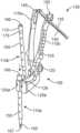
- FIGS. 1 and 2are perspective views showing ne embodiment of a minimally invasive surgery (MIS) compressor/distractor instrument.
- MISminimally invasive surgery
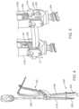
- FIG. 3is a perspective view showing the compressor/distractor instrument engaged with a spinal fixation system 200 .
- FIGS. 4 - 7are views showing the operation of the compressor/distractor instrument.
- FIG. 8is an enlarged perspective view showing details of a hinge pull pin of the compressor/distractor instrument.
- Some of the current compressor/distractor instrumentsrequire a separate driver to be inserted down through the implant or screw extender to access the set screw.
- Other compress/distractor instrumentsprovide bending support to the screw extender or implant exteriorly.
- Still othersutilize a hinge pull pin style compression/tension release but lack a locking feature.
- the present inventionaddresses these problems by using support tubes that provide two functions, the first is the compressor/distractor instrument provides strength internally to the tower or implant during compression or distraction manipulation and to also engage the set screw for reduction and tightening/loosening purposes.
- the compressor/distractor instrumentutilizes support tubes are positioned internally in the screw extenders.
- the compressor/distractor instrumentincludes a pull pin that utilizes a ball lock mechanism that secures the hinged handles together.
- a spring loaded push buttonreleases the ball and allows the pin to be removed, allowing the handles freedom for removal from the tower or implant.
- FIGS. 1 and 2show one embodiment of a minimally invasive surgery (MIS) compressor/distractor instrument 100 comprising a compressor/distractor device 105 and compressor/distractor support tubes 110 a , 110 b.
- MISminimally invasive surgery
- the compressor/distractor device 105includes left and right handles 115 a , 115 b that are pivotably hinged together by a removable locking pin 120 .
- the distal ends of the left and right handles 115 a . 115 binclude left and right tube engagement arms 125 a , 125 b having an opening 126 configured to receive the compressor/distractor support tubes 110 a , 110 b and pedicle screw extenders 215 (see FIG. 3 ).
- the compressor/distractor support tubes 110 a , 110 binclude a tubular body 155 having a central lumen 160 housing a screw driving shaft 165 .
- the body 155is configured to fit within the openings 126 on the tube engagement arms 125 a , 125 b .
- the tubular body 155further includes a proximal cap 170 having a male threaded portion 175 configured to engage female threads on the pedicle screw extenders 215 on the support tube openings of the engagement arms 125 a , 125 b .
- the compressor/distractor support tubes 110 a , 110 bare also configured to fit within screw extensions 215 and provide bending support screw extensions 215 during compression or distractor manipulation (see FIG. 3 ).
- the compressor/distractor device 105further includes a locking feature 130 on the proximal end of the left and right handles 115 a , 115 b being configured to lock the left and right handles 115 a , 115 b at a desired position.
- the locking feature 130comprises a locking arm 135 having plurality of teeth 140 pivotably attached 145 to the proximal end of left arm 115 a .
- the proximal end of the right arm 115 bincludes an arm lock 150 configured to releasably engage the locking arm 135 and the teeth 140 to lock the left and right handles 115 a , 115 b movement of the compressor/distractor device 105 during compression or distraction.
- the locking arm 135 and arm lock 140are also configured to disengage when needed so that the left and right handles 115 a , 115 b can be moved away from each.
- FIGS. 3 - 7show the compressor/distractor device 105 in use with a spinal fixation system 200 having pedicle screws 205 attached to two or more vertebrae (not shown) coupled to a fixation rod 210 .
- Screw extenders 215are removably attached to the pedicle screws 205 to assist in assembling and adjusting the spinal fixation system 200 .
- the screw extenders 215include a tubular body with a central opening or lumen extending through the body.
- the proximal end of the screw extenders 215include female threads.
- the compressor/distractor support tubes 110 a , 110 bare sized to fit within the lumen and the male threads 175 engage the female threads to hold the support tubes in place and provide bending support of the screw extenders 215 during compression or distractor manipulation of the compressor/distractor device 105 .
- the pedicle screws 205include a body member or head 220 that includes a U-shaped channel or slot 225 to accept the fixation rod 210 .
- a set screw 230is used to threadably engage the body member 220 of the screw assembly to secure the fixation rod 210 within the body member 220 .
- the proximal end 166 of the screw driving shaft 165is configured to engage a screw driver or other tool 300 .
- the distal end of the screw driving shaft 167is configured to engage and rotate the set screw 230 to reduce and seat the fixation rod 210 in the U-shaped channel or slot 225 of the screw head 220 .
- the compressor/distractor support tubes 110 a , 110 bprovide internal set screw engagement for threaded reduction capabilities of the rod, while also providing bending support of the screw extensions during compression or distractor manipulation of the compressor/distractor device 105 .
- the compressor/distractor support tube 110is slide into the top of the openings 126 to the support tube engagement arms 125 a , 125 b compressor/distractor 105 and the screw extenders 215 are slid into the bottom of the openings 126 .
- the male threads 175 of the compressor/distractor support tubes 110are then coupled to the female threads of the screw extenders 200 .
- the distal end 167 of the screw driving shaft 165are configured to engaged with the set screws 225 .
- the left and right handles 115 a . 115 b of the compressor/distractor device 105are then moved to compress or distract the screw extenders 200 , with the compressor/distractor support tubes 110 providing support for the screw extenders 200 .
- the locking feature 130locks the left and right handles 115 a . 115 b in place.
- FIG. 4shows a screwdriver or other instrument 300 coupled to the proximal end 166 of the first screw driving shaft 165 to rotate the set screw 230 to reduce the fixation rod 210 into the u-shaped channel 225 of the body member 220 and lock the fixation rod in place.
- FIG. 5shows the fixation rod reduction on the left tube.
- the inside lumen of the left screw extension 215 L and screw head 220include female threads configured to engage male threads of the set screw 230 .
- the distal end 167rotates the set screw 230 down the threads, which pushes the fixation rod 210 downward D into the U-shaped channel 225 .
- FIG. 6shows the screwdriver 300 coupled to the proximal end 166 of the second screw driving shaft 165 to rotate the set screw 230 to reduce the fixation rod 210 into the u-shaped channel 225 of the body member 220 and lock the fixation rod in place.
- FIG. 7shows the fixation rod reduction on the right tube.
- the inside lumen of the right screw extension 215 R and screw head 220include female threads configured to engage male threads of the set screw 230 .
- the distal end 167rotates the set screw 230 down the threads, which pushes the fixation rod 210 downward D into the U-shaped channel 225 .
- FIG. 7the fixation rod 225 had been reduced into the screw heads 220 and is fixed in place.
- the compressor/distractor instrument 100may now be removed.
- the pull pin 120may be pulled so that the left and right handles 115 a , 115 b are separated.
- the pull pin 120may utilize a ball lock mechanism that secures the hinged handles together.
- a spring loaded push buttonreleases the ball and allows the pin to be removed, allowing the handles freedom for removal from the tower or implant.
- the compressor/distractor support tubes 110 a , 110 bare disengaged from the screw extensions 215 .
- the compressor/distractor support tubes 110 a , 110 bare pulled from the screw extensions, and the left and right handles 115 a , 115 b handles removed.
Landscapes
- Health & Medical Sciences (AREA)
- Orthopedic Medicine & Surgery (AREA)
- Neurology (AREA)
- Surgery (AREA)
- Life Sciences & Earth Sciences (AREA)
- Molecular Biology (AREA)
- Heart & Thoracic Surgery (AREA)
- Medical Informatics (AREA)
- Biomedical Technology (AREA)
- Animal Behavior & Ethology (AREA)
- General Health & Medical Sciences (AREA)
- Public Health (AREA)
- Veterinary Medicine (AREA)
- Engineering & Computer Science (AREA)
- Nuclear Medicine, Radiotherapy & Molecular Imaging (AREA)
- Surgical Instruments (AREA)
Abstract
Description
- The use of additional instruments and steps is inefficient and potentially leads to complications.
- Exterior support of the screw extenders require a larger incision.
- Hinge pins without a locking feature are susceptible to disassembly.
Claims (15)
Priority Applications (1)
| Application Number | Priority Date | Filing Date | Title |
|---|---|---|---|
| US16/581,724US11678912B2 (en) | 2019-09-24 | 2019-09-24 | Minimally invasive compressor / distractor |
Applications Claiming Priority (1)
| Application Number | Priority Date | Filing Date | Title |
|---|---|---|---|
| US16/581,724US11678912B2 (en) | 2019-09-24 | 2019-09-24 | Minimally invasive compressor / distractor |
Publications (2)
| Publication Number | Publication Date |
|---|---|
| US20210085370A1 US20210085370A1 (en) | 2021-03-25 |
| US11678912B2true US11678912B2 (en) | 2023-06-20 |
Family
ID=74881531
Family Applications (1)
| Application Number | Title | Priority Date | Filing Date |
|---|---|---|---|
| US16/581,724ActiveUS11678912B2 (en) | 2019-09-24 | 2019-09-24 | Minimally invasive compressor / distractor |
Country Status (1)
| Country | Link |
|---|---|
| US (1) | US11678912B2 (en) |
Families Citing this family (2)
| Publication number | Priority date | Publication date | Assignee | Title |
|---|---|---|---|---|
| CN113491546B (en)* | 2021-08-06 | 2022-12-09 | 山东中医药大学附属医院 | Pelvis osteotomy distractor |
| US11806053B2 (en)* | 2022-02-28 | 2023-11-07 | Orthofix Us Llc | Polymeric vertebral retaining devices |
Citations (13)
| Publication number | Priority date | Publication date | Assignee | Title |
|---|---|---|---|---|
| US20050177173A1 (en) | 1998-10-02 | 2005-08-11 | Max Aebi | Spinal disc space distractor |
| US20090171391A1 (en)* | 2007-10-23 | 2009-07-02 | Alphatec Spine, Inc. | Systems and methods for spinal fixation |
| US20100004695A1 (en)* | 2008-07-07 | 2010-01-07 | Depuy Spine, Inc. | System and method for manipulating a spinal construct |
| US20110106082A1 (en) | 2009-10-30 | 2011-05-05 | Warsaw Orthopedic, Inc. | Instruments and systems for vertebral column manipulation |
| US20120271308A1 (en) | 2009-08-28 | 2012-10-25 | Stryker Trauma Ag | Surgical clamping device |
| US20140277198A1 (en)* | 2013-03-14 | 2014-09-18 | DePuy Synthes Products, LLC | Methods and devices for polyaxial screw alignment |
| US20150066088A1 (en)* | 2013-09-05 | 2015-03-05 | Warsaw Orthopedic, Inc. | Surgical instrument and method |
| US20150351814A1 (en)* | 2012-01-16 | 2015-12-10 | K2M, Inc. | Rod reducer, compressor, distractor system |
| US20180256215A1 (en)* | 2017-03-09 | 2018-09-13 | Alphatec Spine, Inc. | Osteotomy instrument |
| US20180271566A1 (en)* | 2015-12-02 | 2018-09-27 | Aesculap Ag | Medical instrument and medical instrumentarium |
| US20190110785A1 (en)* | 2017-10-18 | 2019-04-18 | Spine Wave, Inc. | Screw-based retractor with expandable blades |
| US20190209080A1 (en)* | 2017-07-03 | 2019-07-11 | Spine Align, Llc | Intraoperative alignment assessment system and method |
| US20200093614A1 (en)* | 2018-09-24 | 2020-03-26 | Simplify Medical Pty Ltd | Robotic systems and methods for distraction in intervertebral disc prosthesis implantation |
- 2019
- 2019-09-24USUS16/581,724patent/US11678912B2/enactiveActive
Patent Citations (13)
| Publication number | Priority date | Publication date | Assignee | Title |
|---|---|---|---|---|
| US20050177173A1 (en) | 1998-10-02 | 2005-08-11 | Max Aebi | Spinal disc space distractor |
| US20090171391A1 (en)* | 2007-10-23 | 2009-07-02 | Alphatec Spine, Inc. | Systems and methods for spinal fixation |
| US20100004695A1 (en)* | 2008-07-07 | 2010-01-07 | Depuy Spine, Inc. | System and method for manipulating a spinal construct |
| US20120271308A1 (en) | 2009-08-28 | 2012-10-25 | Stryker Trauma Ag | Surgical clamping device |
| US20110106082A1 (en) | 2009-10-30 | 2011-05-05 | Warsaw Orthopedic, Inc. | Instruments and systems for vertebral column manipulation |
| US20150351814A1 (en)* | 2012-01-16 | 2015-12-10 | K2M, Inc. | Rod reducer, compressor, distractor system |
| US20140277198A1 (en)* | 2013-03-14 | 2014-09-18 | DePuy Synthes Products, LLC | Methods and devices for polyaxial screw alignment |
| US20150066088A1 (en)* | 2013-09-05 | 2015-03-05 | Warsaw Orthopedic, Inc. | Surgical instrument and method |
| US20180271566A1 (en)* | 2015-12-02 | 2018-09-27 | Aesculap Ag | Medical instrument and medical instrumentarium |
| US20180256215A1 (en)* | 2017-03-09 | 2018-09-13 | Alphatec Spine, Inc. | Osteotomy instrument |
| US20190209080A1 (en)* | 2017-07-03 | 2019-07-11 | Spine Align, Llc | Intraoperative alignment assessment system and method |
| US20190110785A1 (en)* | 2017-10-18 | 2019-04-18 | Spine Wave, Inc. | Screw-based retractor with expandable blades |
| US20200093614A1 (en)* | 2018-09-24 | 2020-03-26 | Simplify Medical Pty Ltd | Robotic systems and methods for distraction in intervertebral disc prosthesis implantation |
Non-Patent Citations (2)
| Title |
|---|
| International Search Preliminary Report on Patentability in PCT Application No. PCT/US2019/052803 dated Apr. 24, 2020. |
| Ternational Search Report and Written Opinion in PCT Application No. PCT/US2019/052803 dated Nov. 15, 2019. |
Also Published As
| Publication number | Publication date |
|---|---|
| US20210085370A1 (en) | 2021-03-25 |
Similar Documents
| Publication | Publication Date | Title |
|---|---|---|
| US20210259746A1 (en) | Method and instruments for interbody fusion and posterior fixation through a single incision | |
| US11633216B2 (en) | Spondylisthesis reduction system | |
| US10335209B2 (en) | Systems and methods for spinal fixation | |
| US8821502B2 (en) | Instrument and method for spinal compression and distraction | |
| US10660631B1 (en) | Pedicle screw mounted retractor system | |
| US9545271B2 (en) | Rod inserter and methods of use | |
| US8096996B2 (en) | Rod reducer | |
| US20180098788A1 (en) | Surgical access port stabilization | |
| CA2581882A1 (en) | Connector transfer tool for internal structure stabilization systems | |
| US11678913B2 (en) | Articulating derotators for deformity spinal systems and methods for use thereof | |
| US11678912B2 (en) | Minimally invasive compressor / distractor | |
| US12414864B2 (en) | Two-piece spine implant installation instrument for use with an endoscope and method of use | |
| WO2020068882A1 (en) | Minimally invasive compressor / distractor | |
| US20240000487A1 (en) | Mis multi-level compressor / distractor |
Legal Events
| Date | Code | Title | Description |
|---|---|---|---|
| FEPP | Fee payment procedure | Free format text:ENTITY STATUS SET TO UNDISCOUNTED (ORIGINAL EVENT CODE: BIG.); ENTITY STATUS OF PATENT OWNER: SMALL ENTITY | |
| FEPP | Fee payment procedure | Free format text:ENTITY STATUS SET TO SMALL (ORIGINAL EVENT CODE: SMAL); ENTITY STATUS OF PATENT OWNER: SMALL ENTITY | |
| AS | Assignment | Owner name:ASTURA MEDICAL INC., CALIFORNIA Free format text:ASSIGNMENT OF ASSIGNORS INTEREST;ASSIGNORS:KLAUSMAN, KEITH;PURCELL, THOMAS;GAMBRELL, JOEL;SIGNING DATES FROM 20190930 TO 20200217;REEL/FRAME:051882/0728 | |
| STPP | Information on status: patent application and granting procedure in general | Free format text:RESPONSE TO NON-FINAL OFFICE ACTION ENTERED AND FORWARDED TO EXAMINER | |
| STPP | Information on status: patent application and granting procedure in general | Free format text:FINAL REJECTION MAILED | |
| STPP | Information on status: patent application and granting procedure in general | Free format text:ADVISORY ACTION MAILED | |
| STPP | Information on status: patent application and granting procedure in general | Free format text:DOCKETED NEW CASE - READY FOR EXAMINATION | |
| STPP | Information on status: patent application and granting procedure in general | Free format text:NON FINAL ACTION MAILED | |
| STPP | Information on status: patent application and granting procedure in general | Free format text:RESPONSE TO NON-FINAL OFFICE ACTION ENTERED AND FORWARDED TO EXAMINER | |
| STPP | Information on status: patent application and granting procedure in general | Free format text:FINAL REJECTION MAILED | |
| STCF | Information on status: patent grant | Free format text:PATENTED CASE |