US11678871B2 - Balloon pulling device and manufacturing method therefor - Google Patents
Balloon pulling device and manufacturing method thereforDownload PDFInfo
- Publication number
- US11678871B2 US11678871B2US16/976,407US201816976407AUS11678871B2US 11678871 B2US11678871 B2US 11678871B2US 201816976407 AUS201816976407 AUS 201816976407AUS 11678871 B2US11678871 B2US 11678871B2
- Authority
- US
- United States
- Prior art keywords
- balloon
- core tube
- pulling device
- tube
- expansion
- Prior art date
- Legal status (The legal status is an assumption and is not a legal conclusion. Google has not performed a legal analysis and makes no representation as to the accuracy of the status listed.)
- Active
Links
Images


Classifications
- A—HUMAN NECESSITIES
- A61—MEDICAL OR VETERINARY SCIENCE; HYGIENE
- A61B—DIAGNOSIS; SURGERY; IDENTIFICATION
- A61B17/00—Surgical instruments, devices or methods
- A61B17/02—Surgical instruments, devices or methods for holding wounds open, e.g. retractors; Tractors
- A—HUMAN NECESSITIES
- A61—MEDICAL OR VETERINARY SCIENCE; HYGIENE
- A61B—DIAGNOSIS; SURGERY; IDENTIFICATION
- A61B17/00—Surgical instruments, devices or methods
- A61B17/02—Surgical instruments, devices or methods for holding wounds open, e.g. retractors; Tractors
- A61B17/0218—Surgical instruments, devices or methods for holding wounds open, e.g. retractors; Tractors for minimally invasive surgery
- A—HUMAN NECESSITIES
- A61—MEDICAL OR VETERINARY SCIENCE; HYGIENE
- A61M—DEVICES FOR INTRODUCING MEDIA INTO, OR ONTO, THE BODY; DEVICES FOR TRANSDUCING BODY MEDIA OR FOR TAKING MEDIA FROM THE BODY; DEVICES FOR PRODUCING OR ENDING SLEEP OR STUPOR
- A61M25/00—Catheters; Hollow probes
- A61M25/10—Balloon catheters
- A61M25/1011—Multiple balloon catheters
- A—HUMAN NECESSITIES
- A61—MEDICAL OR VETERINARY SCIENCE; HYGIENE
- A61M—DEVICES FOR INTRODUCING MEDIA INTO, OR ONTO, THE BODY; DEVICES FOR TRANSDUCING BODY MEDIA OR FOR TAKING MEDIA FROM THE BODY; DEVICES FOR PRODUCING OR ENDING SLEEP OR STUPOR
- A61M29/00—Dilators with or without means for introducing media, e.g. remedies
- A61M29/02—Dilators made of swellable material
- B—PERFORMING OPERATIONS; TRANSPORTING
- B29—WORKING OF PLASTICS; WORKING OF SUBSTANCES IN A PLASTIC STATE IN GENERAL
- B29C—SHAPING OR JOINING OF PLASTICS; SHAPING OF MATERIAL IN A PLASTIC STATE, NOT OTHERWISE PROVIDED FOR; AFTER-TREATMENT OF THE SHAPED PRODUCTS, e.g. REPAIRING
- B29C49/00—Blow-moulding, i.e. blowing a preform or parison to a desired shape within a mould; Apparatus therefor
- B29C49/02—Combined blow-moulding and manufacture of the preform or the parison
- B29C49/04—Extrusion blow-moulding
- A—HUMAN NECESSITIES
- A61—MEDICAL OR VETERINARY SCIENCE; HYGIENE
- A61B—DIAGNOSIS; SURGERY; IDENTIFICATION
- A61B17/00—Surgical instruments, devices or methods
- A61B2017/00526—Methods of manufacturing
- A—HUMAN NECESSITIES
- A61—MEDICAL OR VETERINARY SCIENCE; HYGIENE
- A61B—DIAGNOSIS; SURGERY; IDENTIFICATION
- A61B17/00—Surgical instruments, devices or methods
- A61B2017/00535—Surgical instruments, devices or methods pneumatically or hydraulically operated
- A61B2017/00557—Surgical instruments, devices or methods pneumatically or hydraulically operated inflatable
- A—HUMAN NECESSITIES
- A61—MEDICAL OR VETERINARY SCIENCE; HYGIENE
- A61B—DIAGNOSIS; SURGERY; IDENTIFICATION
- A61B17/00—Surgical instruments, devices or methods
- A61B17/22—Implements for squeezing-off ulcers or the like on inner organs of the body; Implements for scraping-out cavities of body organs, e.g. bones; for invasive removal or destruction of calculus using mechanical vibrations; for removing obstructions in blood vessels, not otherwise provided for
- A61B2017/22051—Implements for squeezing-off ulcers or the like on inner organs of the body; Implements for scraping-out cavities of body organs, e.g. bones; for invasive removal or destruction of calculus using mechanical vibrations; for removing obstructions in blood vessels, not otherwise provided for with an inflatable part, e.g. balloon, for positioning, blocking, or immobilisation
- A61B2017/22055—Implements for squeezing-off ulcers or the like on inner organs of the body; Implements for scraping-out cavities of body organs, e.g. bones; for invasive removal or destruction of calculus using mechanical vibrations; for removing obstructions in blood vessels, not otherwise provided for with an inflatable part, e.g. balloon, for positioning, blocking, or immobilisation with three or more balloons
- A—HUMAN NECESSITIES
- A61—MEDICAL OR VETERINARY SCIENCE; HYGIENE
- A61M—DEVICES FOR INTRODUCING MEDIA INTO, OR ONTO, THE BODY; DEVICES FOR TRANSDUCING BODY MEDIA OR FOR TAKING MEDIA FROM THE BODY; DEVICES FOR PRODUCING OR ENDING SLEEP OR STUPOR
- A61M25/00—Catheters; Hollow probes
- A61M2025/0008—Catheters; Hollow probes having visible markings on its surface, i.e. visible to the naked eye, for any purpose, e.g. insertion depth markers, rotational markers or identification of type
- A—HUMAN NECESSITIES
- A61—MEDICAL OR VETERINARY SCIENCE; HYGIENE
- A61M—DEVICES FOR INTRODUCING MEDIA INTO, OR ONTO, THE BODY; DEVICES FOR TRANSDUCING BODY MEDIA OR FOR TAKING MEDIA FROM THE BODY; DEVICES FOR PRODUCING OR ENDING SLEEP OR STUPOR
- A61M25/00—Catheters; Hollow probes
- A61M25/0009—Making of catheters or other medical or surgical tubes
Definitions
- the present inventionrelates to the field of medical equipment, in particular to a balloon pulling device and a manufacturing method thereof.
- Retractorsalso known as pull hooks, are used to retract tissues, reveal the scope of surgery, and facilitate exploration and operation. They can be divided into hand-held retractors and automatic retractors. There are various specifications of different shapes and sizes, and the appropriate retractor can be selected according to the needs of the operation.
- the traditional retractorrequires a large operating space, which requires a large surgical wound.
- traditional retractorsare mostly made of metal and have sharp ends, which are likely to cause secondary trauma to patients and damage important organs.
- the catheter retractoris used for tissue retraction during surgery and the product can complete the retraction operation through natural cavity intervention or open surgical intervention.
- Surgeryincludes, but is not limited to, various types of laparoscopic surgery, cardiovascular surgery, brain surgery, gastrointestinal surgery, urinary disease surgery, etc.
- the tissues to be retractedinclude but are not limited to gastrointestinal tract, esophagus, airway, urethra, vagina, bladder, etc.
- the purpose of retractionincludes but is not limited to protecting specific tissues and removing specific tissues to facilitate surgical operations.
- a balloon catheter retractor as shown in FIG. 1comprising: a catheter 5 with an air valve at one end, a balloon 4 arranged on the periphery of the catheter 5 , one or more cavities in the catheter, and the catheter part of the tube is inflated or deflated, and the balloon 4 will bend to one side when inflated.
- the material of the balloon 4is non-compliant, and the two ends 3 are sealed on the catheter 5 by laser welding.
- the curved balloon shown in FIG. 1uses a single balloon, which places higher requirements on the material and degree of curvature of the balloon. Only by accurately calculating and testing the balloon material can the retraction of a specific operation be achieved. Distance requirements. This brings difficulties to the preparation of such curved balloons and puts forward higher technical requirements. In some specific operations, the curvature of a single balloon may not achieve the required retraction distance.
- the purpose of the present inventionis to provide a curved balloon for natural channel intervention or open surgical intervention to complete the retraction operation based on the above-mentioned problems, which solves the problem that the current catheter retractor has complex structure, inconvenient operation, and large product diameter and cannot pass through.
- the narrow, complicated structure of the cavity, the inability to accurately control the pulling force, the low reliability and other problems, the present inventionrealizes a simple and reliable balloon pulling device that can realize a larger distance and can be precisely adjusted.
- the present inventionprovides a balloon pulling device, which includes a core tube and a balloon part.
- the core tube partcan inflate and release fluid to the balloon part.
- the balloon partis characterized in that the balloon part includes several expansion sections. The inflation section is larger than the rest of the balloon after being filled with fluid, so that the entire balloon is bent.
- the core tubeis flexible and has a plurality of long strips of cavities therein. There is at least one hole on the surface of the core tube, or there is a corresponding hole for each expansion section, encapsulated or attached to the core tube.
- the axis of the balloonis on one side of the axis of the core tube.
- the core tubecan be a number of independent core tubes, each core tube individually or separately controls the inflation or charging and discharging of several balloon inflation or expansion segments; or it can also be a multi-lumen tube, each tube individually controlling the inflation or charging and discharging of several balloon inflation or expansion segments.
- each balloonhas multiple expansion sections, so that each balloon can be individually controlled to bend or each balloon can individually control the bending.
- the two ends of the balloonare connected with a wire-like material with low ductility.
- the recommended parameters of the ballooncan be any one or several of the following groups:
- the length of the expanded section of the balloonis greater than its outer diameter in the unexpanded state.
- the adjacent intervals between the inflation or expanded segments of the balloonare less than 0.2 times the length of the inflation or expanded segments.
- the present inventionalso provides a method for manufacturing a balloon pulling device, which includes the following steps: using a splicing mold or die to make the material form a balloon on the balloon forming machine; after cooling, the mold is removed and the balloon is taken out; The cavity core tube is bored and punched in the core tube; the balloon is placed in a preset or predetermined position, and the balloon is fixed on the core tube by welding or glue bonding.
- the moldis divided into two parts, and the shape of the inner or internal cavity after the splicing of the two petal molds is consistent with the final outer contour of the balloon. Cooling is by external water cooling until it is consistent with the ambient temperature.
- the core tubeis extruded by an extruder to form a single-lumen or multi-lumen tube.
- the manufacturing methodalso includes after fixing the balloon to the core tube, using a wire-like or ductile material with low ductility, fixing one end near the distal end of the core tube, and fixing the other end near the proximal end of the core tube, and then combining the filament material with core tube by bonding.
- the filamentous or filamentary materialcan be a metal that is not easily ductile, that is, a metal with a larger modulus.
- the two ends of the metal wireare fixed near the distal end of the core tube, that is, the distal end of the balloon, and near the proximal end of the core tube, that is, the proximal end of the balloon.
- the core tubeshould be a multi-lumen tube or a combination of multiple single-lumen tubes, and each balloon has at least one corresponding to the core tube.
- the opening at the locationis used to charge and discharge fluid.
- the inventionrealizes a simple and reliable balloon pulling device that can realize a larger distance of retraction and can be accurately or precisely adjusted.
- FIG. 1is a schematic diagram of a conventional balloon pulling device
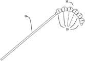
- FIG. 2is a schematic diagram of the balloon pulling device of the present invention
- FIG. 3is a schematic diagram of the balloon pulling device of the present invention filled with fluid
- FIG. 4is a cross-sectional view of the balloon pulling device of the present invention.
- FIG. 5is a partial enlarged view of the cross-section of the balloon pulling device of the present invention.
- the present inventionproposes the idea of forming a balloon into multiple expansion sections connected in series, and each expansion section is, after being filled with fluid and expanded, squeezed to form a bend.
- each expansion sectionis, after being filled with fluid and expanded, squeezed to form a bend.
- both the inflated or expanded section and the non-inflated or non-expanded sectionwill inflate after the overall inflation or filling.
- the expansion section and the non-expansion sectionare pressed against each other, or will squeeze each other, and because of the eccentricity, the entire axis of the balloon is elongated, and the axis of the core tube is elongated very little, resulting in bending.
- the first balloon inflation and second balloon inflationwill squeeze each other, which will cause the whole to bend, but under this bending scheme, the rigidity of the hollow between the first balloon and the second balloon is very low, so it suffers from external interference. It's easy to straighten. It is also possible to use multiple such balloons to accumulate or to achieve greater bending or to achieve bending of different shapes.
- FIG. 2is a schematic diagram of the balloon pulling device of the present invention.
- the balloon pulling device as shown in FIG. 2mainly consists of two parts, a core tube or core catheter 11 and a balloon 12 covering the core tube or core catheter 11 .
- the balloon 12includes a plurality of expansion segments or sections 13 , and a plurality of non-expandable parts located between the expansion sections 13 .
- the balloon 12is located at the middle and rear end of the core tube 11 .
- the core tube 11is a tube having a hollow lumen. Because it needs to be inserted into the patient's body and can be pulled by the balloon 12 , the core tube 11 is usually a long, flexible plastic or plastic tube with good biocompatibility.
- the core tube 11can fill and discharge the balloon 12 with fluid.
- FIG. 2is a state not filled with fluid. In this state, the expansion section 13 has not yet expanded, which is slightly larger than the non-expansion section.
- the inflation or expansion section 13is larger than the rest of the balloon 12 after being filled with fluid. After each inflation section 13 is filled with fluid, it squeezes or is pressed together with the non-inflation or non-expanded section, so that the entire balloon 12 is bent.
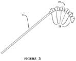
- FIG. 3is a schematic diagram of the balloon retractor or pulling device of the present invention filled with fluid.
- each expansion section 13 of the balloon 12is filled with fluid to expand and squeeze or press against each other to form a curved profile.
- each expansion section 13is located on one side of the core tube 11 , so that each expansion section 13 will accumulate the degree of bending after being filled with fluid, that is, expansion.
- each balloon 12may be individually control the bending of a part of the core tube 11 shape.
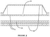
- FIG. 4is a cross-sectional view of the balloon retractor or pulling device of the present invention
- FIG. 5is a partial enlarged view of the cross-sectional view of the balloon retractor of the present invention.
- the core tube 11has holes 14 on the surface covered by the balloon 12 or has corresponding holes 14 for each expansion section 13 .
- the core tube 11can be a plurality of independent core tubes 11 , each core tube 11 individually controls the inflation and discharging of the inflation section 13 of a single balloon 12 ; it can also be a multi-lumen tube, each of which individually controls a single balloon 12 charge and discharge, or expansion and contraction, of the expansion section 13 .
- the inflation or expansion sections 13 of the balloon 12may be connected to or in communication with each other through a non-inflatable section, or may be various independent and disconnected inflated sections, for example, composed of multiple independent small inflatable balloons or each section of the non-inflated section is tightly tied. Both ends of the balloon may be connected with a wire-like material 15 with low ductility.
- the filamentous material 15may be disposed in the lumen of the core tube 11 as shown in FIG. 5 , or may be disposed on the outer surface of the core tube.
- the filamentary material 15is made of a metal material with a relatively large modulus, such as metal, to ensure that the corresponding part of the core tube will not be elongated when the balloon 12 is inflated, thereby reducing the degree of bending and causing deformation of the core tube.
- the length of the inflation or expanded section 13 of the balloon 12is greater than the outer diameter of the uninflated or unexpanded state.
- the adjacent interval between the expansion sections 13 of the balloon 12is less than 0.2 times the length of the expansion section 13 .
- the balloon retractor or pulling deviceis extended into the patient's lumen (minimally invasive lumen or natural lumen), and part of the fluid is first filled (preferably, the internal pressure is between 1-4 atmospheric pressure), and the distal balloon 12 will be visibly bent.
- the imaging deviceis used for positioning, and the handle is rotated and pushed to make the angle and position of the device reach the desired state. Then continue filling the device with liquid (preferably, the internal pressure of the device reaches between 4-6 atmospheres), and the balloon 12 will remain bent to the maximum extent, thereby achieving the purpose of pulling away the target tissue.
- the present inventionalso provides a method for manufacturing a balloon retractor or pulling device including the following steps:
- thermoplastic polymer materialis selected, melted and extruded into a barrel or material tube. Milling the balloon forming mold, the mold is divided into two halves, and the shape of the inner cavity after the two mold halves are spliced is consistent with the final outer contour of the balloon 12 .
- the spliced moldis placed on the balloon forming machine, and the material tube is placed in the cavity. Set the molding temperature, molding internal pressure and stretching rate, stretch and expand the material tube so that the outer wall of the final material tube is adhered or applied to the inner wall of the mold cavity. After the material tube is completely adhered or applied to the inner wall of the mold cavity, maintain the molding pressure and start at the same time external water cooling.
- the balloon 12has an expansion section 13 part and a non-expansion section part according to the shape of the mold. It is also possible to disregard the expansion and non-expansion parts, and restrict the non-expansion part after the balloon 12 is set to the preset position so that it cannot be expanded significantly.
- the core tube 11is extruded, a thermoplastic polymer material is selected, and then extruded after melting to form a single-lumen or multi-lumen tube.
- the filamentary material 15should be a metal wire with less ductility (large modulus), one end fixed near the distal end of the core tube 11 (preferably the distal end of the balloon 12 ). The other end is fixed near the proximal end of the core tube 11 (preferably the proximal end of the balloon 12 ), and glue is used to bond the filamentous material 15 and the core tube 11 together.
- the preparation method in the case of multiple balloonsfirstly select a thermoplastic polymer material, melt it and extrude it into a barrel or material tube. Milling the balloon forming mold, the mold is divided into two halves, and the shape of the internal cavity after the two mold halves are spliced is consistent with the final outer contour of the single balloon 12 .
- the spliced moldis placed on a balloon forming machine, and the material tube is placed in the cavity. Set the molding temperature, molding internal pressure and stretching rate, stretch and expand the material tube so that the outer wall of the final material tube is adhered or applied to the inner wall of the mold cavity. After the material tube is completely adhered or applied to the inner wall of the entire mold cavity, maintain the molding pressure and start at the same time external water cooling.
- the balloon 12has an expansion section 13 part and a non-expansion section part according to the shape of the mold. It is also possible to disregard the expansion and non-expansion parts, and restrict the non-expansion part after the balloon 12 is set to the preset position so that it cannot be expanded significantly.
- the core tube 11is extruded, and a thermoplastic polymer material is selected, melted, and extruded to form a multi-lumen tube having a number of cavities greater than or equal to the number of balloons 12 needed.
- a catheter puncheris used to punch holes 14 in the multi-lumen tube.
- the number of holes 14is the same as the number of balloons used.
- the axial distance between two adjacent holes 14should be slightly greater than the length of the balloon 12 , preferably, the distance is the sum of the length of the balloon 12 and the predetermined gap between the balloons 12 .
- a plurality of balloons 12are placed in preset positions, and the balloons 12 are fixed on the core tube 11 by welding or adhesive bonding, respectively.
- the manufacturing methodalso includes after fixing the balloon to the core tube, fixing one end of the filamentous material 15 near the distal end of the core tube 11 , and fixing the other end near the proximal end of the core tube 11 , and then attaching the filamentous material 15 to the core tube.
- the tube 11is glued.
Landscapes
- Health & Medical Sciences (AREA)
- Life Sciences & Earth Sciences (AREA)
- Engineering & Computer Science (AREA)
- Surgery (AREA)
- Heart & Thoracic Surgery (AREA)
- Animal Behavior & Ethology (AREA)
- Veterinary Medicine (AREA)
- Biomedical Technology (AREA)
- General Health & Medical Sciences (AREA)
- Public Health (AREA)
- Molecular Biology (AREA)
- Medical Informatics (AREA)
- Nuclear Medicine, Radiotherapy & Molecular Imaging (AREA)
- Mechanical Engineering (AREA)
- Manufacturing & Machinery (AREA)
- Hematology (AREA)
- Anesthesiology (AREA)
- Vascular Medicine (AREA)
- Child & Adolescent Psychology (AREA)
- Biophysics (AREA)
- Pulmonology (AREA)
- Media Introduction/Drainage Providing Device (AREA)
- Surgical Instruments (AREA)
Abstract
Description
Claims (10)
Applications Claiming Priority (3)
| Application Number | Priority Date | Filing Date | Title |
|---|---|---|---|
| CN201810165074.9 | 2018-02-27 | ||
| CN201810165074.9ACN110192901A (en) | 2018-02-27 | 2018-02-27 | Sacculus pulling device and its manufacturing method |
| PCT/CN2018/103279WO2019165772A1 (en) | 2018-02-27 | 2018-08-30 | Balloon pulling device and manufacturing method therefor |
Publications (2)
| Publication Number | Publication Date |
|---|---|
| US20210113202A1 US20210113202A1 (en) | 2021-04-22 |
| US11678871B2true US11678871B2 (en) | 2023-06-20 |
Family
ID=67750982
Family Applications (1)
| Application Number | Title | Priority Date | Filing Date |
|---|---|---|---|
| US16/976,407ActiveUS11678871B2 (en) | 2018-02-27 | 2018-08-30 | Balloon pulling device and manufacturing method therefor |
Country Status (5)
| Country | Link |
|---|---|
| US (1) | US11678871B2 (en) |
| EP (1) | EP3760131A4 (en) |
| JP (1) | JP7108698B2 (en) |
| CN (1) | CN110192901A (en) |
| WO (1) | WO2019165772A1 (en) |
Families Citing this family (12)
| Publication number | Priority date | Publication date | Assignee | Title |
|---|---|---|---|---|
| CN111419304A (en)* | 2020-04-16 | 2020-07-17 | 上海科赐医疗技术有限公司 | Curved balloon catheter retractor |
| CN112546404A (en)* | 2021-01-19 | 2021-03-26 | 山东第一医科大学附属省立医院(山东省立医院) | Anti-damage catheter with function of accidental pulling out |
| CN112957589A (en)* | 2021-02-19 | 2021-06-15 | 上海科赐医疗技术有限公司 | Balloon catheter retractor |
| CN115487402A (en)* | 2021-06-18 | 2022-12-20 | 上海科赐医疗技术有限公司 | Anti-torsion bending balloon device |
| CN113456143A (en)* | 2021-08-10 | 2021-10-01 | 西安交通大学医学院第一附属医院 | Double-balloon anastomat for digestive tract reconstruction |
| CN113796821B (en)* | 2021-09-24 | 2024-05-07 | 南方科技大学 | Enteroscopy system with autonomous bending function and autonomous bending method thereof |
| CN113941074B (en)* | 2021-11-12 | 2024-05-24 | 北京大学深圳医院 | Pharyngeal expansion device for gastroscopy of elderly patients |
| JP2025517345A (en)* | 2022-05-17 | 2025-06-05 | ボストン サイエンティフィック サイムド,インコーポレイテッド | Devices, systems and methods for tissue retraction |
| CN115700126A (en)* | 2022-11-10 | 2023-02-07 | 复旦大学附属中山医院 | Interventional catheter assembly capable of being bent in oriented mode |
| CN116328160A (en)* | 2023-04-11 | 2023-06-27 | 中国人民解放军西部战区总医院 | An ERCP-assisted bile duct superselection device |
| CN118648851B (en)* | 2024-08-19 | 2025-02-07 | 湖南省华芯医疗器械有限公司 | Active bending section, insertion portion and endoscope |
| CN119244858B (en)* | 2024-12-05 | 2025-03-25 | 四川中科高新技术集团有限公司 | Drainage pipe trenchless repair airbag |
Citations (27)
| Publication number | Priority date | Publication date | Assignee | Title |
|---|---|---|---|---|
| US4763654A (en) | 1986-09-10 | 1988-08-16 | Jang G David | Tandem independently inflatable/deflatable multiple diameter balloon angioplasty catheter systems and method of use |
| USD303288S (en) | 1986-09-12 | 1989-09-05 | Ballobes Aps | Intragastric balloon kit consisting of an intragastric balloon device, a pump, a container tube and a box |
| US4862886A (en) | 1985-05-08 | 1989-09-05 | Summit Technology Inc. | Laser angioplasty |
| US5147377A (en) | 1988-11-23 | 1992-09-15 | Harvinder Sahota | Balloon catheters |
| CN2120592U (en) | 1992-03-21 | 1992-11-04 | 仇德惠 | Catheter for esophagus operation |
| USD360260S (en) | 1993-02-09 | 1995-07-11 | Montefiore Hospital And Medical Center | Esophageal cytology balloon catheter |
| USD390659S (en) | 1997-03-31 | 1998-02-10 | Bristol-Myers Squibb Company | Bone cement scoop |
| US20060085022A1 (en) | 2004-10-15 | 2006-04-20 | Kelli Hayes | Non-compliant medical balloon having an integral woven fabric layer |
| US20080306583A1 (en) | 2001-08-31 | 2008-12-11 | Boston Scientific Scimed, Inc. | Hybrid ballon expandable/self-expanding stent |
| US20080312589A1 (en) | 2005-08-19 | 2008-12-18 | Abbott Laboratories Vascular Enterprises Limited | Method of Producing a Ballon Catheter |
| CN201333252Y (en) | 2008-12-25 | 2009-10-28 | 毛瑞敏 | Cervical dilator |
| US7837672B2 (en)* | 2002-06-11 | 2010-11-23 | Boston Scientific Scimed, Inc. | Adjustable double balloon catheter with a through lumen for stone management |
| US20120150210A1 (en) | 2010-11-12 | 2012-06-14 | Smith & Nephew Inc. | Inflatable, steerable balloon for elevation of tissue within a body |
| CN103055411A (en) | 2013-01-25 | 2013-04-24 | 业聚医疗器械(深圳)有限公司 | Balloon catheter and manufacturing method thereof |
| US20140012304A1 (en) | 2012-07-03 | 2014-01-09 | Merit Medical Systems, Inc. | Multilayered balloon |
| US20140066939A1 (en)* | 2009-03-17 | 2014-03-06 | Pivot Medical, Inc. | Method and apparatus for distracting a joint |
| WO2014096370A2 (en) | 2012-12-21 | 2014-06-26 | University College Cork, National University Of Ireland, Cork | An inflatable laparoscopic retractor for atraumatic retraction in abdominal surgery |
| US20140243875A1 (en) | 2010-09-22 | 2014-08-28 | Boston Scientific Scimed, Inc. | Medical balloon having improved stability and strength |
| CN104189989A (en) | 2014-09-19 | 2014-12-10 | 广州启骏生物科技有限公司 | Bleeding stop balloon catheter and production method thereof |
| CN204581372U (en) | 2015-04-24 | 2015-08-26 | 中国人民解放军总医院 | A kind of chamber mirror rectum fixes pulling device |
| CN104921853A (en) | 2015-06-25 | 2015-09-23 | 四川大学华西医院 | Esophagus strutting arrangement |
| WO2016077358A1 (en) | 2014-11-13 | 2016-05-19 | Soft Robotics, Inc. | Soft robotic retractors |
| CN105997161A (en) | 2016-04-27 | 2016-10-12 | 凌安东 | Water bag intestine pad applied to laparoscopic operation |
| CN106422038A (en) | 2016-09-28 | 2017-02-22 | 上海凯利泰医疗科技股份有限公司 | Vertebral body expansion balloon catheter |
| USD851245S1 (en) | 2017-04-14 | 2019-06-11 | Cardiofocus, Inc. | Compliant balloon |
| JP1637001S (en) | 2018-07-18 | 2019-07-22 | ||
| US10463468B2 (en) | 2013-03-15 | 2019-11-05 | Insera Therapeutics, Inc. | Thrombus aspiration with different intensity levels |
Family Cites Families (9)
| Publication number | Priority date | Publication date | Assignee | Title |
|---|---|---|---|---|
| US9586022B2 (en)* | 2006-01-25 | 2017-03-07 | Mayser, Llc | Stretch valve balloon catheter and methods for producing and using same |
| CN101198369B (en)* | 2005-06-14 | 2012-06-27 | 瓦羽株式会社 | Ductus bursae |
| US9937329B2 (en)* | 2009-10-06 | 2018-04-10 | Niazi Licensing Corporation | Intra-esophageal balloon system |
| US9839543B2 (en)* | 2013-03-14 | 2017-12-12 | Cook Medical Technologies Llc | Multi-stage balloon catheter |
| EP2805695A1 (en)* | 2013-05-21 | 2014-11-26 | Medtentia International Ltd Oy | Medical system for annuloplasty |
| WO2016141195A1 (en)* | 2015-03-04 | 2016-09-09 | Transmed7, Llc | Steerable, conformable, drug eluting balloon catheter |
| CN107835704B (en)* | 2015-03-27 | 2020-12-15 | 项目莫里股份有限公司 | Fluid drive system for catheter articulation and other uses |
| US20180008444A1 (en)* | 2016-07-11 | 2018-01-11 | Cook Medical Technologies Llc | Multi-stage balloon catheter, and method of operating same in a curved passageway |
| CN107261301A (en)* | 2017-05-04 | 2017-10-20 | 杭州启明医疗器械有限公司 | A kind of foley's tube and preparation method thereof and medical treatment device |
- 2018
- 2018-02-27CNCN201810165074.9Apatent/CN110192901A/enactivePending
- 2018-08-30WOPCT/CN2018/103279patent/WO2019165772A1/ennot_activeCeased
- 2018-08-30USUS16/976,407patent/US11678871B2/enactiveActive
- 2018-08-30JPJP2020545625Apatent/JP7108698B2/enactiveActive
- 2018-08-30EPEP18907619.3Apatent/EP3760131A4/enactivePending
Patent Citations (34)
| Publication number | Priority date | Publication date | Assignee | Title |
|---|---|---|---|---|
| US4862886A (en) | 1985-05-08 | 1989-09-05 | Summit Technology Inc. | Laser angioplasty |
| US4763654A (en) | 1986-09-10 | 1988-08-16 | Jang G David | Tandem independently inflatable/deflatable multiple diameter balloon angioplasty catheter systems and method of use |
| USD303288S (en) | 1986-09-12 | 1989-09-05 | Ballobes Aps | Intragastric balloon kit consisting of an intragastric balloon device, a pump, a container tube and a box |
| US5147377A (en) | 1988-11-23 | 1992-09-15 | Harvinder Sahota | Balloon catheters |
| CN2120592U (en) | 1992-03-21 | 1992-11-04 | 仇德惠 | Catheter for esophagus operation |
| USD360260S (en) | 1993-02-09 | 1995-07-11 | Montefiore Hospital And Medical Center | Esophageal cytology balloon catheter |
| USD390659S (en) | 1997-03-31 | 1998-02-10 | Bristol-Myers Squibb Company | Bone cement scoop |
| US20080306583A1 (en) | 2001-08-31 | 2008-12-11 | Boston Scientific Scimed, Inc. | Hybrid ballon expandable/self-expanding stent |
| US7837672B2 (en)* | 2002-06-11 | 2010-11-23 | Boston Scientific Scimed, Inc. | Adjustable double balloon catheter with a through lumen for stone management |
| US20060085022A1 (en) | 2004-10-15 | 2006-04-20 | Kelli Hayes | Non-compliant medical balloon having an integral woven fabric layer |
| US20080312589A1 (en) | 2005-08-19 | 2008-12-18 | Abbott Laboratories Vascular Enterprises Limited | Method of Producing a Ballon Catheter |
| CN201333252Y (en) | 2008-12-25 | 2009-10-28 | 毛瑞敏 | Cervical dilator |
| US20140066939A1 (en)* | 2009-03-17 | 2014-03-06 | Pivot Medical, Inc. | Method and apparatus for distracting a joint |
| US20140243875A1 (en) | 2010-09-22 | 2014-08-28 | Boston Scientific Scimed, Inc. | Medical balloon having improved stability and strength |
| US20120150210A1 (en) | 2010-11-12 | 2012-06-14 | Smith & Nephew Inc. | Inflatable, steerable balloon for elevation of tissue within a body |
| US20140309646A1 (en) | 2010-11-12 | 2014-10-16 | Smith & Nephew, Inc. | Inflatable, steerable balloon for elevation of tissue within a body |
| US9439705B2 (en) | 2010-11-12 | 2016-09-13 | Smith & Nephew, Inc. | Inflatable, steerable balloon for elevation of tissue within a body |
| US8795312B2 (en) | 2010-11-12 | 2014-08-05 | Smith & Nephew, Inc. | Inflatable, steerable balloon for elevation of tissue within a body |
| CN103442650A (en) | 2010-11-12 | 2013-12-11 | 史密夫和内修有限公司 | Inflatable, steerable balloon for elevation of tissue within a body |
| US20140012304A1 (en) | 2012-07-03 | 2014-01-09 | Merit Medical Systems, Inc. | Multilayered balloon |
| US20150342590A1 (en) | 2012-12-21 | 2015-12-03 | University College Cork, National University Of Ireland, Cork | Inflatable laparoscopic retractor for atraumatic retraction in abdominal surgery |
| WO2014096370A2 (en) | 2012-12-21 | 2014-06-26 | University College Cork, National University Of Ireland, Cork | An inflatable laparoscopic retractor for atraumatic retraction in abdominal surgery |
| US20170150957A9 (en) | 2012-12-21 | 2017-06-01 | University College Cork, National University Of Ireland, Cork | Inflatable laparoscopic retractor for atraumatic retraction in abdominal surgery |
| CN103055411A (en) | 2013-01-25 | 2013-04-24 | 业聚医疗器械(深圳)有限公司 | Balloon catheter and manufacturing method thereof |
| US10463468B2 (en) | 2013-03-15 | 2019-11-05 | Insera Therapeutics, Inc. | Thrombus aspiration with different intensity levels |
| CN104189989A (en) | 2014-09-19 | 2014-12-10 | 广州启骏生物科技有限公司 | Bleeding stop balloon catheter and production method thereof |
| WO2016077358A1 (en) | 2014-11-13 | 2016-05-19 | Soft Robotics, Inc. | Soft robotic retractors |
| CN204581372U (en) | 2015-04-24 | 2015-08-26 | 中国人民解放军总医院 | A kind of chamber mirror rectum fixes pulling device |
| CN104921853A (en) | 2015-06-25 | 2015-09-23 | 四川大学华西医院 | Esophagus strutting arrangement |
| CN105997161A (en) | 2016-04-27 | 2016-10-12 | 凌安东 | Water bag intestine pad applied to laparoscopic operation |
| CN106422038A (en) | 2016-09-28 | 2017-02-22 | 上海凯利泰医疗科技股份有限公司 | Vertebral body expansion balloon catheter |
| USD851245S1 (en) | 2017-04-14 | 2019-06-11 | Cardiofocus, Inc. | Compliant balloon |
| JP1637001S (en) | 2018-07-18 | 2019-07-22 | ||
| USD879958S1 (en) | 2018-07-18 | 2020-03-31 | Shanghaí Kecì Medical Technology Co., Ltd. | Medical balloon Group |
Also Published As
| Publication number | Publication date |
|---|---|
| JP7108698B2 (en) | 2022-07-28 |
| WO2019165772A1 (en) | 2019-09-06 |
| CN110192901A (en) | 2019-09-03 |
| EP3760131A1 (en) | 2021-01-06 |
| US20210113202A1 (en) | 2021-04-22 |
| EP3760131A4 (en) | 2021-09-29 |
| JP2021514763A (en) | 2021-06-17 |
Similar Documents
| Publication | Publication Date | Title |
|---|---|---|
| US11678871B2 (en) | Balloon pulling device and manufacturing method therefor | |
| US5833657A (en) | Single-walled balloon catheter with non-linear compliance characteristic | |
| JP3339003B2 (en) | Inflatable medical device for delivering a drug and method of making the same | |
| US5226880A (en) | Angioplasty catheter with balloon retainer | |
| EP3641676B1 (en) | Introducer for uterine tamponade assembly | |
| US8961532B2 (en) | Atraumatic catheter tip | |
| US10617849B2 (en) | Balloon with variable pitch reinforcing fibers | |
| EP2421592B1 (en) | Balloon catheter | |
| EP0745395B1 (en) | Adjustable balloon membrane made from peek material | |
| JPH09503678A (en) | Balloon catheter sheath | |
| CN110621373B (en) | Multilayer balloon | |
| JPH11514891A (en) | Low profile balloon catheter and method | |
| WO2001054568A1 (en) | Cavity enlarger method and apparatus | |
| WO1997003716A1 (en) | Distensible pet balloon and method of manufacture | |
| WO2006128194A2 (en) | Balloon-in-balloon cervical canal dilator | |
| EP3329959B1 (en) | Treatment instrument for endoscope | |
| EP1507571B1 (en) | Dilator for body passageway | |
| US9402983B1 (en) | Variably expanding balloon catheter | |
| CN114191686A (en) | Balloon catheter for fistulization | |
| CN110200667B (en) | Soft channel for neuroendoscopy operation and establishing method | |
| WO2023081072A1 (en) | Uterine tamponade device | |
| JP2019520890A (en) | Multilayer balloon | |
| CN219127925U (en) | Catheter and kit for TIPS operation | |
| CN114681765A (en) | Dilatation balloon and balloon dilatation catheter | |
| HK1007518B (en) | An angioplasty catheter and a method of making the same |
Legal Events
| Date | Code | Title | Description |
|---|---|---|---|
| AS | Assignment | Owner name:SHANGHAI KECI MEDICAL TECHNOLOGY CO., LTD, CHINA Free format text:ASSIGNMENT OF ASSIGNORS INTEREST;ASSIGNORS:ZHANG, CHUANHAI;ZHANG, ZHICHAO;REEL/FRAME:053620/0146 Effective date:20200826 | |
| FEPP | Fee payment procedure | Free format text:ENTITY STATUS SET TO UNDISCOUNTED (ORIGINAL EVENT CODE: BIG.); ENTITY STATUS OF PATENT OWNER: SMALL ENTITY | |
| FEPP | Fee payment procedure | Free format text:ENTITY STATUS SET TO SMALL (ORIGINAL EVENT CODE: SMAL); ENTITY STATUS OF PATENT OWNER: SMALL ENTITY | |
| STPP | Information on status: patent application and granting procedure in general | Free format text:APPLICATION DISPATCHED FROM PREEXAM, NOT YET DOCKETED | |
| STPP | Information on status: patent application and granting procedure in general | Free format text:DOCKETED NEW CASE - READY FOR EXAMINATION | |
| STPP | Information on status: patent application and granting procedure in general | Free format text:NON FINAL ACTION MAILED | |
| STPP | Information on status: patent application and granting procedure in general | Free format text:RESPONSE TO NON-FINAL OFFICE ACTION ENTERED AND FORWARDED TO EXAMINER | |
| STPP | Information on status: patent application and granting procedure in general | Free format text:NON FINAL ACTION MAILED | |
| STCF | Information on status: patent grant | Free format text:PATENTED CASE |