US11678650B2 - Distribution device - Google Patents
Distribution deviceDownload PDFInfo
- Publication number
- US11678650B2 US11678650B2US16/167,594US201816167594AUS11678650B2US 11678650 B2US11678650 B2US 11678650B2US 201816167594 AUS201816167594 AUS 201816167594AUS 11678650 B2US11678650 B2US 11678650B2
- Authority
- US
- United States
- Prior art keywords
- shuttle
- coupled
- spreader
- motor
- meter
- Prior art date
- Legal status (The legal status is an assumption and is not a legal conclusion. Google has not performed a legal analysis and makes no representation as to the accuracy of the status listed.)
- Active, expires
Links
- 241000238557DecapodaSpecies0.000claimsabstractdescription10
- 238000004519manufacturing processMethods0.000claimsabstractdescription10
- 238000004891communicationMethods0.000claimsabstractdescription5
- 230000007613environmental effectEffects0.000claimsabstractdescription5
- 230000008878couplingEffects0.000claimsdescription5
- 238000010168coupling processMethods0.000claimsdescription5
- 238000005859coupling reactionMethods0.000claimsdescription5
- 230000004913activationEffects0.000claimsdescription4
- XLYOFNOQVPJJNP-UHFFFAOYSA-NwaterSubstancesOXLYOFNOQVPJJNP-UHFFFAOYSA-N0.000claimsdescription3
- 230000000284resting effectEffects0.000claims2
- 230000001276controlling effectEffects0.000description4
- 239000000463materialSubstances0.000description3
- 238000012986modificationMethods0.000description2
- 230000004048modificationEffects0.000description2
- 238000010276constructionMethods0.000description1
- 238000013461designMethods0.000description1
- 239000003337fertilizerSubstances0.000description1
- 238000005259measurementMethods0.000description1
- 238000012544monitoring processMethods0.000description1
- 235000015097nutrientsNutrition0.000description1
- 238000012545processingMethods0.000description1
- 230000001105regulatory effectEffects0.000description1
- 239000013589supplementSubstances0.000description1
Images


Classifications
- A—HUMAN NECESSITIES
- A01—AGRICULTURE; FORESTRY; ANIMAL HUSBANDRY; HUNTING; TRAPPING; FISHING
- A01K—ANIMAL HUSBANDRY; AVICULTURE; APICULTURE; PISCICULTURE; FISHING; REARING OR BREEDING ANIMALS, NOT OTHERWISE PROVIDED FOR; NEW BREEDS OF ANIMALS
- A01K61/00—Culture of aquatic animals
- A01K61/50—Culture of aquatic animals of shellfish
- A01K61/59—Culture of aquatic animals of shellfish of crustaceans, e.g. lobsters or shrimps
- A—HUMAN NECESSITIES
- A01—AGRICULTURE; FORESTRY; ANIMAL HUSBANDRY; HUNTING; TRAPPING; FISHING
- A01K—ANIMAL HUSBANDRY; AVICULTURE; APICULTURE; PISCICULTURE; FISHING; REARING OR BREEDING ANIMALS, NOT OTHERWISE PROVIDED FOR; NEW BREEDS OF ANIMALS
- A01K5/00—Feeding devices for stock or game ; Feeding wagons; Feeding stacks
- A01K5/02—Automatic devices
- A01K5/0266—Automatic devices with stable trolleys, e.g. suspended
- A—HUMAN NECESSITIES
- A01—AGRICULTURE; FORESTRY; ANIMAL HUSBANDRY; HUNTING; TRAPPING; FISHING
- A01K—ANIMAL HUSBANDRY; AVICULTURE; APICULTURE; PISCICULTURE; FISHING; REARING OR BREEDING ANIMALS, NOT OTHERWISE PROVIDED FOR; NEW BREEDS OF ANIMALS
- A01K5/00—Feeding devices for stock or game ; Feeding wagons; Feeding stacks
- A01K5/02—Automatic devices
- A01K5/0275—Automatic devices with mechanisms for delivery of measured doses
- A—HUMAN NECESSITIES
- A01—AGRICULTURE; FORESTRY; ANIMAL HUSBANDRY; HUNTING; TRAPPING; FISHING
- A01K—ANIMAL HUSBANDRY; AVICULTURE; APICULTURE; PISCICULTURE; FISHING; REARING OR BREEDING ANIMALS, NOT OTHERWISE PROVIDED FOR; NEW BREEDS OF ANIMALS
- A01K61/00—Culture of aquatic animals
- A01K61/80—Feeding devices
- A01K61/85—Feeding devices for use with aquaria
- A—HUMAN NECESSITIES
- A22—BUTCHERING; MEAT TREATMENT; PROCESSING POULTRY OR FISH
- A22C—PROCESSING MEAT, POULTRY, OR FISH
- A22C29/00—Processing shellfish or bivalves, e.g. oysters, lobsters; Devices therefor, e.g. claw locks, claw crushers, grading devices; Processing lines
- A22C29/02—Processing shrimps, lobsters or the like ; Methods or machines for the shelling of shellfish
- A22C29/023—Conveying, feeding or aligning shellfish
- A—HUMAN NECESSITIES
- A01—AGRICULTURE; FORESTRY; ANIMAL HUSBANDRY; HUNTING; TRAPPING; FISHING
- A01K—ANIMAL HUSBANDRY; AVICULTURE; APICULTURE; PISCICULTURE; FISHING; REARING OR BREEDING ANIMALS, NOT OTHERWISE PROVIDED FOR; NEW BREEDS OF ANIMALS
- A01K63/00—Receptacles for live fish, e.g. aquaria; Terraria
- A01K63/04—Arrangements for treating water specially adapted to receptacles for live fish
- Y—GENERAL TAGGING OF NEW TECHNOLOGICAL DEVELOPMENTS; GENERAL TAGGING OF CROSS-SECTIONAL TECHNOLOGIES SPANNING OVER SEVERAL SECTIONS OF THE IPC; TECHNICAL SUBJECTS COVERED BY FORMER USPC CROSS-REFERENCE ART COLLECTIONS [XRACs] AND DIGESTS
- Y02—TECHNOLOGIES OR APPLICATIONS FOR MITIGATION OR ADAPTATION AGAINST CLIMATE CHANGE
- Y02A—TECHNOLOGIES FOR ADAPTATION TO CLIMATE CHANGE
- Y02A40/00—Adaptation technologies in agriculture, forestry, livestock or agroalimentary production
- Y02A40/80—Adaptation technologies in agriculture, forestry, livestock or agroalimentary production in fisheries management
- Y02A40/81—Aquaculture, e.g. of fish
Definitions
- the disclosurerelates to distribution devices and more particularly pertains to a new feed distribution device developed for automating and metering distribution of feed in a commercial shrimp production facility utilizing a stacked shallow tank configuration but applicable to distribution of other matter over tanks, fields, pens, or the like.
- An embodiment of the disclosuremeets the needs presented above by generally comprising an elongated support surface positioned over and extending along an elongated tank having an open top.
- a shuttlemoves along the support surface to move along a length of the tank.
- a hopper to hold feedis coupled to the shuttle.
- a spreaderis in environmental communication with the hopper to distribute feed from the hopper and a meter is operationally coupled between the hopper and the spreader for controlling an amount of the feed delivered to and distributed by the spreader.
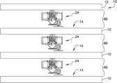
- FIG. 1is a front view of a distribution device according to an embodiment of the disclosure.
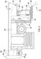
- FIG. 2is a side view of an embodiment of the disclosure.
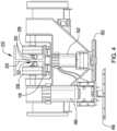
- FIG. 3is a rear view of an embodiment of the disclosure.
- FIG. 4is a front view of an embodiment of the disclosure.
- FIG. 5is a bottom view of an embodiment of the disclosure.
- FIG. 6is a schematic view of an embodiment of the disclosure.
- FIGS. 1 through 6a new feeding distribution device embodying the principles and concepts of an embodiment of the disclosure and generally designated by the reference numeral 10 will be described.
- the distribution device 10generally comprises a tank 12 of the type which is conventional in commercial production of shrimp.
- the tank 12is elongated and has an open top 14 .
- the device 10generally may be utilized for distribution of matter other than feed and applicable to other situations than commercial shrimp operations.
- the tank 12may further represent any area, enclosed or open, onto or into which matter, including feed, nutrients, fertilizer, supplements, or the like, may be distributed.
- a beam 16is positioned over the tank 12 .
- the beam 16is elongated and extends along a length of the tank 12 .
- the beam 16includes a lower flange 18 and a central flange 20 .
- the central flange 20is coupled to and extends perpendicularly from the lower flange 18 .
- the lower flange 18defines a support surface 22 .
- the beam 16may be an I-beam or have an inverted T-shaped cross sectional shape taken perpendicular to a longitudinal axis of the beam 16 .
- the beam 16may also be viewed as integrally incorporated into any structure positioned over the tank 12 such as another tank 12 in a vertically stacked orientation with the original tank 12 .
- a shuttle 24is movable along the support surface 22 wherein the shuttle 24 is movable along a length of the tank 12 .
- the shuttle 24comprises a frame 26 and a plurality of rollers 28 .
- the rollers 28are coupled to the frame 26 .
- the rollers 28engage the beam 16 wherein the shuttle 24 is slidably coupled to the beam 16 .
- Each roller 28rests on a top surface 30 of the lower flange 18 of the beam 16 coextensive with the support surface 22 .
- Each of a pair of guide wheels 30is coupled to the frame 26 and extends from the frame 26 towards the central flange 20 of the beam 16 such that the central flange 20 of the beam 16 is positioned within a gap 32 defined between the pair of guide wheels 30 .
- a drive wheel 34is coupled to the frame 26 .
- the drive wheel 34engages the beam 16 wherein rotation of the drive wheel 34 urges the frame 26 to move along the beam 16 .
- the drive wheel 34engages a bottom surface 36 of the lower flange 18 of the beam 16 .
- a drive motor 38is coupled to the frame 26 .
- the drive motor 38is operationally engaged to the drive wheel 34 wherein activation of the drive motor 38 rotates the drive wheel 34 to move the shuttle 24 along the beam 16 in a selectable direction.
- a load cell 40is coupled to the frame 26 .
- a hopper 42is coupled to the frame 26 .
- the hopper 42is configured for receiving and holding feed 44 .
- the hopper 42may hold matter other than feed 44 if so desired.
- the hopper 42is pivotally coupled to the frame 26 at a position over the load cell 40 wherein the hopper 42 is gravitationally urged to rest on the load cell 40 such that the load cell 40 is configured to measure an amount of feed 44 inside the hopper 42 by pressure exerted on the load cell 40 by the hopper 42 .
- a spreader 46is coupled to the frame 26 .
- the spreader 46is of the type conventionally known which uses a rotated disc for distribution over an adjacent area.
- the spreader 46is in environmental communication with the hopper 42 wherein rotation of the spreader 42 is configured to distribute feed 44 from the hopper 42 .
- a spreader motor 48is coupled to the frame 26 .
- the spreader motor 48is operationally engaged to the spreader 46 wherein the spreader motor 48 urges the spreader 46 to rotate.
- the spreader motor 48is operationally coupled to the spreader 46 such that a speed of rotation of the spreader 46 is variable wherein the spreader 46 is configured for distributing the feed 44 over a desired and selectable area.
- a meter 50is coupled to the frame 26 .
- the meter 50is operationally coupled between the hopper 42 and the spreader 46 wherein the meter 50 is configured for controlling an amount of the feed 44 delivered to and distributed by the spreader 46 .
- the meter 50is also of a conventional metering design controlled by movement of components regulating an amount of material being distributed by the meter 50 and may be controlled by rotation of a component of the meter 50 .
- a meter motor 52is coupled to the frame 26 .
- the meter motor 52is operationally engaged to the meter 50 urging the meter 50 to rotate.
- the meter motor 52is operationally coupled to the meter 50 such that a speed of rotation of the meter 50 is variable wherein the meter 50 is configured for controlling a rate of distribution of the feed 44 from the hopper 42 .
- a processor 54is coupled to the frame 26 .
- the processor 54is electrically and communicatively coupled to each of the drive motor 38 , the spreader motor 48 , and the meter motor 52 wherein the processor 54 controls movement of the shuttle 24 along the beam 16 and is configured for controlling rate and area for distribution of the feed 44 from the hopper 42 .
- the processor 54is also operationally coupled to the load cell 40 for receiving and processing input relating to contents of the hopper 42 .
- a base 56is positioned at a first end 58 of the beam 16 .
- the base 56is configured for coupling to an electrical power source in a conventional manner.
- the base 56has a base contact 60 .
- a battery 62is coupled to the shuttle 24 .
- the battery 62is electrically coupled to each of the processor 54 , the drive motor 38 , the spreader motor 48 , and the meter motor 52 .
- a shuttle contact 64is positioned on and electrically coupled to the battery 62 . The shuttle contact 64 engages the base contact 60 when the shuttle 24 is positioned at the first end 58 of the beam 16 wherein the battery 62 is configured to be charged by the electrical power source.
- the tank 12is one of a plurality of tanks 12 wherein each of the tanks 12 is elongated and the tanks 12 are vertically stacked.
- the tanksare vertically spaced defining a clearance space 66 between adjacently stacked tanks 12 .
- the clearance spaceis typically no greater than 20 inches.
- the support surface 22is one of a plurality of support surfaces 22 , each support surface 22 being positioned over an associated one of the tanks 12 .
- Each support surface 22extends along a length of the associated tank 12 .
- the shuttle 24is one of a plurality of shuttles 24 , each shuttle 24 being movable along an associated one of the support surfaces 22 .
- a processing center 68is operationally and communicatively coupled to each processor 54 wherein the processing center 68 is configured to monitor and control operation of each shuttle 24 and distribution of the feed 44 .
- the tanks 12may be further arranged into laterally aligned vertical stacks, as shown in FIG. 6 , or in any other configuration desired.
- the processing center 68may be utilized for tracking of distribution history, monitoring actual distribution amounts based on load cell measurements, and may coordinate distribution from each shuttle.
- the device 10may be incorporated and utilized for metered and controlled distribution over any area, tank, pen, or field but is designed primarily to fit within the confines of spacing between vertically stacked tanks in a commercial shrimp production facility.
- the processing center 68may be used to coordinate operation of each shuttle 24 for distribution of feed 44 into the tanks 12 .
- the overall systemmay be automated for metered distribution over time 24 hours per day or limited to distinct amounts at distinct times.
- the operationmay further be coordinated with other factors such as water quality or any other measurable input which may influence when and how much matter is to be distributed. It is also contemplated that structures may be put into place for automated filling of each hopper 42 .
Landscapes
- Life Sciences & Earth Sciences (AREA)
- Environmental Sciences (AREA)
- Animal Husbandry (AREA)
- Biodiversity & Conservation Biology (AREA)
- Zoology (AREA)
- Marine Sciences & Fisheries (AREA)
- Engineering & Computer Science (AREA)
- Birds (AREA)
- Wood Science & Technology (AREA)
- Food Science & Technology (AREA)
- Farming Of Fish And Shellfish (AREA)
Abstract
Description
Claims (17)
Priority Applications (1)
| Application Number | Priority Date | Filing Date | Title |
|---|---|---|---|
| US16/167,594US11678650B2 (en) | 2018-10-23 | 2018-10-23 | Distribution device |
Applications Claiming Priority (1)
| Application Number | Priority Date | Filing Date | Title |
|---|---|---|---|
| US16/167,594US11678650B2 (en) | 2018-10-23 | 2018-10-23 | Distribution device |
Publications (2)
| Publication Number | Publication Date |
|---|---|
| US20200120904A1 US20200120904A1 (en) | 2020-04-23 |
| US11678650B2true US11678650B2 (en) | 2023-06-20 |
Family
ID=70281038
Family Applications (1)
| Application Number | Title | Priority Date | Filing Date |
|---|---|---|---|
| US16/167,594Active2039-09-21US11678650B2 (en) | 2018-10-23 | 2018-10-23 | Distribution device |
Country Status (1)
| Country | Link |
|---|---|
| US (1) | US11678650B2 (en) |
Families Citing this family (1)
| Publication number | Priority date | Publication date | Assignee | Title |
|---|---|---|---|---|
| CN111657331B (en)* | 2020-06-12 | 2021-12-28 | 广州中臣碧阳科技集团有限公司 | Marine euphausia superba distribution station |
Citations (16)
| Publication number | Priority date | Publication date | Assignee | Title |
|---|---|---|---|---|
| US3695415A (en)* | 1970-07-28 | 1972-10-03 | Butler Manufacturing Co | Feeder for livestock |
| US4223638A (en)* | 1979-01-24 | 1980-09-23 | Sappington Marr D | Apparatus for feeding poultry |
| US4811675A (en)* | 1985-10-23 | 1989-03-14 | Ska S.P.A. | Apparatus for automatic and continuous dispensing of food in feeding troughs for battery-reared poultry |
| US4981107A (en)* | 1989-03-31 | 1991-01-01 | Micro-Contact Inc. | Computerized automatic cattle-feeder system |
| US5069165A (en)* | 1990-10-12 | 1991-12-03 | Victor Rousseau | Livestock feeder system |
| US5076215A (en)* | 1991-01-14 | 1991-12-31 | Yang Ning C | Automatic timing device of sprinkling fish meal for fishpond |
| US5377624A (en) | 1993-05-07 | 1995-01-03 | The Cultured Abalone Incorporated | Abalone farming system |
| US5505160A (en)* | 1994-08-16 | 1996-04-09 | A. Pellerin Et Fils Ltee. | Feed distributing apparatus |
| US6234111B1 (en)* | 1999-04-29 | 2001-05-22 | Research Diets, Inc. | Animal feeder, feeder mount, feeder monitor, and feeder monitoring network |
| US6305323B1 (en) | 1999-08-26 | 2001-10-23 | Pao-Ling Tsai | Apparatus and a method and system of rearing abalone |
| US6779486B2 (en)* | 2001-10-17 | 2004-08-24 | Feedlogic Systems Inc. | Automatic animal feeder |
| CN2682930Y (en) | 2004-02-23 | 2005-03-09 | 谭荣兵 | Embedded type advertisement armchair |
| US20060124071A1 (en) | 2002-08-19 | 2006-06-15 | Watermark Seafoods Pty Ltd | System for harvesting crustaceans |
| US20140168411A1 (en) | 2012-12-19 | 2014-06-19 | Laitram, L.L.C. | Shrimp processing system and methods |
| CN205213882U (en) | 2015-12-23 | 2016-05-11 | 云南农业大学 | South america white shrimp scale breeding device |
| WO2016077928A1 (en) | 2014-11-19 | 2016-05-26 | Budd Marvyn | Indoor shrimp aquaculture system and method |
- 2018
- 2018-10-23USUS16/167,594patent/US11678650B2/enactiveActive
Patent Citations (16)
| Publication number | Priority date | Publication date | Assignee | Title |
|---|---|---|---|---|
| US3695415A (en)* | 1970-07-28 | 1972-10-03 | Butler Manufacturing Co | Feeder for livestock |
| US4223638A (en)* | 1979-01-24 | 1980-09-23 | Sappington Marr D | Apparatus for feeding poultry |
| US4811675A (en)* | 1985-10-23 | 1989-03-14 | Ska S.P.A. | Apparatus for automatic and continuous dispensing of food in feeding troughs for battery-reared poultry |
| US4981107A (en)* | 1989-03-31 | 1991-01-01 | Micro-Contact Inc. | Computerized automatic cattle-feeder system |
| US5069165A (en)* | 1990-10-12 | 1991-12-03 | Victor Rousseau | Livestock feeder system |
| US5076215A (en)* | 1991-01-14 | 1991-12-31 | Yang Ning C | Automatic timing device of sprinkling fish meal for fishpond |
| US5377624A (en) | 1993-05-07 | 1995-01-03 | The Cultured Abalone Incorporated | Abalone farming system |
| US5505160A (en)* | 1994-08-16 | 1996-04-09 | A. Pellerin Et Fils Ltee. | Feed distributing apparatus |
| US6234111B1 (en)* | 1999-04-29 | 2001-05-22 | Research Diets, Inc. | Animal feeder, feeder mount, feeder monitor, and feeder monitoring network |
| US6305323B1 (en) | 1999-08-26 | 2001-10-23 | Pao-Ling Tsai | Apparatus and a method and system of rearing abalone |
| US6779486B2 (en)* | 2001-10-17 | 2004-08-24 | Feedlogic Systems Inc. | Automatic animal feeder |
| US20060124071A1 (en) | 2002-08-19 | 2006-06-15 | Watermark Seafoods Pty Ltd | System for harvesting crustaceans |
| CN2682930Y (en) | 2004-02-23 | 2005-03-09 | 谭荣兵 | Embedded type advertisement armchair |
| US20140168411A1 (en) | 2012-12-19 | 2014-06-19 | Laitram, L.L.C. | Shrimp processing system and methods |
| WO2016077928A1 (en) | 2014-11-19 | 2016-05-26 | Budd Marvyn | Indoor shrimp aquaculture system and method |
| CN205213882U (en) | 2015-12-23 | 2016-05-11 | 云南农业大学 | South america white shrimp scale breeding device |
Also Published As
| Publication number | Publication date |
|---|---|
| US20200120904A1 (en) | 2020-04-23 |
Similar Documents
| Publication | Publication Date | Title |
|---|---|---|
| US11678650B2 (en) | Distribution device | |
| KR20240101575A (en) | Powder hopper, corresponding assembly and corresponding method for gravity-driven feeding of powdered electrode precursor material into the nip of a dry electrode calendar | |
| CN103736599A (en) | Full-automatic flotation reagent quantitative adding system | |
| CN204422036U (en) | A kind of high precision vehicle-mounted continuous balk cargo automatic Weighing metering system | |
| CN102538923A (en) | Continuous measuring electronic belt scale | |
| CN108238455B (en) | Control method for feeding of special-shaped hopper | |
| CN201225912Y (en) | Long ton stock location electronic scale | |
| CN203778349U (en) | Flat-plate pill selecting machine | |
| CA3066992A1 (en) | System and method for automatic tank metering control | |
| CN203737498U (en) | Battery positive and negative pole sizing agent coating machine | |
| CN203970033U (en) | A kind of accurate rice metering case | |
| CN203824624U (en) | Blanking mechanism of particle weighing machine | |
| CN202670791U (en) | Material distribution device | |
| CN206842571U (en) | The ratio tripper that a kind of vanadium titanium is smelted | |
| CN203740153U (en) | Weighing tray structure | |
| CN202230393U (en) | Automatic level controlling means | |
| CN104755887A (en) | Device for determining an amount of bulk material, inlet device for bulk material, cleaning machine for bulk material and corresponding method | |
| CN211810343U (en) | Three-bucket quantitative weighing and filling machine | |
| DE1960107B2 (en) | Weighing mechanism for hot material on feed device - uses hinged vibrating feed channel and load cell producing signal proportional to load to control delivery rate | |
| CN211588689U (en) | Plate shearing machine with prevent material skew mechanism | |
| CN211085439U (en) | Liquid material metering device | |
| CN204528711U (en) | The accurate Coal Blending System of a kind of silo | |
| CN203551060U (en) | Belt weigher and mixing station | |
| CN206457010U (en) | A kind of automatic gauge dispensing equipment | |
| CN213632349U (en) | Double-thread double-core intelligent online bulk bin weighing module |
Legal Events
| Date | Code | Title | Description |
|---|---|---|---|
| FEPP | Fee payment procedure | Free format text:ENTITY STATUS SET TO UNDISCOUNTED (ORIGINAL EVENT CODE: BIG.); ENTITY STATUS OF PATENT OWNER: MICROENTITY | |
| FEPP | Fee payment procedure | Free format text:ENTITY STATUS SET TO MICRO (ORIGINAL EVENT CODE: MICR); ENTITY STATUS OF PATENT OWNER: MICROENTITY | |
| STPP | Information on status: patent application and granting procedure in general | Free format text:NON FINAL ACTION MAILED | |
| STPP | Information on status: patent application and granting procedure in general | Free format text:RESPONSE TO NON-FINAL OFFICE ACTION ENTERED AND FORWARDED TO EXAMINER | |
| STPP | Information on status: patent application and granting procedure in general | Free format text:FINAL REJECTION MAILED | |
| STPP | Information on status: patent application and granting procedure in general | Free format text:RESPONSE AFTER FINAL ACTION FORWARDED TO EXAMINER | |
| STPP | Information on status: patent application and granting procedure in general | Free format text:ADVISORY ACTION MAILED | |
| STPP | Information on status: patent application and granting procedure in general | Free format text:DOCKETED NEW CASE - READY FOR EXAMINATION | |
| STPP | Information on status: patent application and granting procedure in general | Free format text:NON FINAL ACTION MAILED | |
| STPP | Information on status: patent application and granting procedure in general | Free format text:RESPONSE TO NON-FINAL OFFICE ACTION ENTERED AND FORWARDED TO EXAMINER | |
| STPP | Information on status: patent application and granting procedure in general | Free format text:FINAL REJECTION MAILED | |
| STCF | Information on status: patent grant | Free format text:PATENTED CASE |