US11678358B2 - Dynamic downlink reuse in a C-RAN - Google Patents
Dynamic downlink reuse in a C-RANDownload PDFInfo
- Publication number
- US11678358B2 US11678358B2US16/149,294US201816149294AUS11678358B2US 11678358 B2US11678358 B2US 11678358B2US 201816149294 AUS201816149294 AUS 201816149294AUS 11678358 B2US11678358 B2US 11678358B2
- Authority
- US
- United States
- Prior art keywords
- radio points
- cell
- current
- subset
- signature vector
- Prior art date
- Legal status (The legal status is an assumption and is not a legal conclusion. Google has not performed a legal analysis and makes no representation as to the accuracy of the status listed.)
- Active
Links
Images


Classifications
- H04W72/085—
- H—ELECTRICITY
- H04—ELECTRIC COMMUNICATION TECHNIQUE
- H04W—WIRELESS COMMUNICATION NETWORKS
- H04W72/00—Local resource management
- H04W72/50—Allocation or scheduling criteria for wireless resources
- H04W72/54—Allocation or scheduling criteria for wireless resources based on quality criteria
- H04W72/542—Allocation or scheduling criteria for wireless resources based on quality criteria using measured or perceived quality
- H—ELECTRICITY
- H04—ELECTRIC COMMUNICATION TECHNIQUE
- H04L—TRANSMISSION OF DIGITAL INFORMATION, e.g. TELEGRAPHIC COMMUNICATION
- H04L5/00—Arrangements affording multiple use of the transmission path
- H04L5/003—Arrangements for allocating sub-channels of the transmission path
- H04L5/0058—Allocation criteria
- H—ELECTRICITY
- H04—ELECTRIC COMMUNICATION TECHNIQUE
- H04L—TRANSMISSION OF DIGITAL INFORMATION, e.g. TELEGRAPHIC COMMUNICATION
- H04L5/00—Arrangements affording multiple use of the transmission path
- H04L5/003—Arrangements for allocating sub-channels of the transmission path
- H04L5/0048—Allocation of pilot signals, i.e. of signals known to the receiver
- H—ELECTRICITY
- H04—ELECTRIC COMMUNICATION TECHNIQUE
- H04L—TRANSMISSION OF DIGITAL INFORMATION, e.g. TELEGRAPHIC COMMUNICATION
- H04L5/00—Arrangements affording multiple use of the transmission path
- H04L5/0091—Signalling for the administration of the divided path, e.g. signalling of configuration information
- H—ELECTRICITY
- H04—ELECTRIC COMMUNICATION TECHNIQUE
- H04W—WIRELESS COMMUNICATION NETWORKS
- H04W76/00—Connection management
- H04W76/10—Connection setup
- H—ELECTRICITY
- H04—ELECTRIC COMMUNICATION TECHNIQUE
- H04L—TRANSMISSION OF DIGITAL INFORMATION, e.g. TELEGRAPHIC COMMUNICATION
- H04L5/00—Arrangements affording multiple use of the transmission path
- H04L5/003—Arrangements for allocating sub-channels of the transmission path
- H04L5/0053—Allocation of signalling, i.e. of overhead other than pilot signals
- H—ELECTRICITY
- H04—ELECTRIC COMMUNICATION TECHNIQUE
- H04W—WIRELESS COMMUNICATION NETWORKS
- H04W74/00—Wireless channel access
- H04W74/08—Non-scheduled access, e.g. ALOHA
- H04W74/0833—Random access procedures, e.g. with 4-step access
- H—ELECTRICITY
- H04—ELECTRIC COMMUNICATION TECHNIQUE
- H04W—WIRELESS COMMUNICATION NETWORKS
- H04W88/00—Devices specially adapted for wireless communication networks, e.g. terminals, base stations or access point devices
- H04W88/08—Access point devices
- H04W88/085—Access point devices with remote components
Definitions
- a centralized radio access networkis one way to implement base station functionality.
- a single baseband unitBBU
- RPsremote units
- UEsuser equipment
- reuserefers to situations where separate downlink data intended for multiple UEs is simultaneously transmitted to the UEs using the same resource elements (that is, the same time-frequency resource). Typically, these situations arise when the UEs are sufficiently physically separated from each other so that the different downlink transmissions do not interfere with each other when transmitted from differing subsets of RPs. This type of reuse is also referred to as “spatial reuse.”
- One embodimentis directed a system to provide wireless service.
- the systemcomprises a controller and a plurality of radio points.
- Each of the radio pointsis associated with at least one antenna and remotely located from the controller, wherein the plurality of radio points is communicatively coupled to the controller.
- the controller and the plurality of radio pointsare configured to implement a base station in order to provide wireless service to a plurality of user equipment (UEs) using a cell.
- the controlleris communicatively coupled to a core network of a wireless service provider.
- the systemis configured to transmit at least some data to each UE connected to the cell using a respective subset of the radio points.
- the systemis configured to determine the respective subset of the radio points for transmitting to each UE connected to the cell using a signature vector comprising a set of signal reception metrics, each signal reception metric associated with a respective one of the radio points and indicative of the reception of a signal transmitted from the respective UE at one of the radio points.
- the systemis configured to do the following when each UE establishes a new connection with the cell: determine initial signal reception metrics for that UE; and if the system has a stored signature vector associated with that UE and that stored signature vector matches the initial signal reception metrics for that UE, initialize the signature vector for that UE using that stored signature associated with that UE.
- Another embodimentis directed to a system to provide wireless service.
- the systemcomprises a controller and a plurality of radio points.
- Each of the radio pointsis associated with at least one antenna and remotely located from the controller, wherein the plurality of radio points is communicatively coupled to the controller.
- the controller and the plurality of radio pointsare configured to implement a base station in order to provide wireless service to a plurality of user equipment (UEs) using a cell.
- the controlleris communicatively coupled to a core network of a wireless service provider.
- the systemis configured to do the following for each UE connected to the cell: determine a signature vector comprising a set of signal reception metrics, each signal reception metric associated with a respective one of the radio points and indicative of the reception of a signal transmitted from the respective UE at one of the radio points; determine a respective minimum subset of the radio points for transmitting to that UE; determine a respective maximum subset of the radio points for transmitting to that UE; and determine a respective current subset of the radio points for transmitting to that UE based on, at least, the signature vector, the respective minimum subset of the radio points for transmitting to that UE, and the respective maximum subset of the radio points for transmitting to that UE.
- the systemis configured to, for each UE connected to the cell, expand the number of radio points in the minimum subset of the radio points if the respective signature vector for that UE has not been updated at least a predetermined number of times.
- the systemis configured to wirelessly transmit at least some data to each UE connected to the cell using the respective current subset of the radio points determined for that UE based.
- Another embodimentis directed to a system to provide wireless service.
- the systemcomprises a controller and a plurality of radio points.
- Each of the radio pointsis associated with at least one antenna and remotely located from the controller, wherein the plurality of radio points is communicatively coupled to the controller.
- the controller and the plurality of radio pointsare configured to implement a base station in order to provide wireless service to a plurality of user equipment (UEs) using a cell.
- the controlleris communicatively coupled to a core network of a wireless service provider.
- the systemis configured to do the following for each UE connected to the cell: determine a signature vector comprising a set of signal reception metrics, each signal reception metric associated with a respective one of the radio points and indicative of the reception at one of the radio points of a signal transmitted from the respective UE; determine a respective minimum subset of the radio points for transmitting to that UE; determine a respective maximum subset of the radio points for transmitting to that UE; and determine a respective current subset of the radio points for transmitting to that UE based on, at least, the signature vector, the respective minimum subset of the radio points for transmitting to that UE, and the respective maximum subset of the radio points for transmitting to that UE.
- the systemis configured to, for each UE connected to the cell, update the respective current subset of the radio points used to transmit that UE based on at least one of the following: at least one ratio of the actual rate of throughput for at least one UE connected to the cell and an estimated rate of throughput for said at least one UE connected to the cell; at least one processing load at the radio points; and demand from at least one UE connected to the cell to use at least one radio point.
- the systemis configured to wirelessly transmit at least some data to each UE connected to the cell using the respective current subset of the radio points determined for that UE.
- FIG. 1is a block diagram illustrating one exemplary embodiment of a radio access network (RAN) system in which the dynamic reuse techniques described here can be implemented.
- RANradio access network
- FIG. 2comprises a flow chart illustrating one exemplary embodiment of a method of dynamically maintaining a signature vector in a C-RAN.
- FIG. 3comprises a flow chart illustrating one exemplary embodiment of a method of determining a minimum simulcast zone and a maximum simulcast zone for a UE in a C-RAN.
- FIGS. 4 A- 4 Bcomprise a flow chart illustrating one exemplary embodiment of a method of dynamically managing a simulcast zone for a UE in a C-RAN.
- FIGS. 5 A- 5 Bcomprise a flow chart illustrating one exemplary embodiment of a method of dynamically managing a link adaptation variable used to initialize and dynamically update the modulation and coding scheme (MCS) used to communicate with a UE in a C-RAN.
- MCSmodulation and coding scheme
- FIG. 1is a block diagram illustrating one exemplary embodiment of a radio access network (RAN) system 100 in which the dynamic reuse techniques described here can be implemented.
- the system 100is deployed at a site 102 to provide wireless coverage and capacity for one or more wireless network operators.
- the site 102may be, for example, a building or campus or other grouping of buildings (used, for example, by one or more businesses, governments, other enterprise entities) or some other public venue (such as a hotel, resort, amusement park, hospital, shopping center, airport, university campus, arena, or an outdoor area such as a ski area, stadium or a densely-populated downtown area).
- the system 100is implemented at least in part using a C-RAN (point-to-multipoint distributed base station) architecture that employs at least one baseband unit 104 and multiple radio points (RPs) 106 serve at least one cell 103 .
- the system 100is also referred to here as a “C-RAN system” 100 .
- the baseband units 104are also referred to here as “baseband controllers” 104 or just “controllers” 104 .
- Each RP 106includes or is coupled to one or more antennas 108 via which downlink RF signals are radiated to user equipment (UE) 110 and via which uplink RF signals transmitted by UEs 110 are received.
- UEuser equipment
- each RP 106comprises two antennas 108 .
- Each RP 106can include or be coupled to a different number of antennas 108 .
- the system 100is coupled to the core network 112 of each wireless network operator over an appropriate back-haul.
- the Internet 114is used for back-haul between the system 100 and each core network 112 .
- the back-haulcan be implemented in other ways.
- LTELong Term Evolution
- eNodeBeNodeB
- VoIPVoice over LTE
- each core network 112is implemented as an Evolved Packet Core (EPC) 112 comprising standard LTE EPC network elements such as, for example, a mobility management entity (MME) (not shown) and a Serving Gateway (SGW) (not shown) and, optionally, a Home eNodeB gateway (HeNB GW) (not shown) and a Security Gateway (SeGW) (not shown).
- EPCEvolved Packet Core
- MMEmobility management entity
- SGWServing Gateway
- HeNB GWHome eNodeB gateway
- SeGWSecurity Gateway
- each controller 104communicates with the MME and SGW in the EPC core network 112 using the LTE Si interface and communicates with other eNodeBs using the LTE X2 interface.
- the controller 104can communicate with an outdoor macro eNodeB (not shown) via the LTE X2 interface.
- Each controller 104 and the radio points 106can be implemented so as to use an air interface that supports one or more of frequency-division duplexing (FDD) and/or time-division duplexing (TDD). Also, the controller 104 and the radio points 106 can be implemented to use an air interface that supports one or more of the multiple-input-multiple-output (MIMO), single-input-single-output (SISO), single-input-multiple-output (SIMO), multiple-input-single-output (MISO), and/or beam forming schemes. For example, the controller 104 and the radio points 106 can implement one or more of the LTE transmission modes. Moreover, the controller 104 and/or the radio points 106 can be configured to support multiple air interfaces and/or to support multiple wireless operators.
- FDDfrequency-division duplexing
- TDDtime-division duplexing
- MIMOmultiple-input-multiple-output
- SISOsingle-input-single
- the front-haul that communicatively couples each controller 104 to the one or more RPs 106is implemented using a standard ETHERNET network 116 .
- ETHERNET network 116the front-haul between the controllers 104 and RPs 106 can be implemented in other ways.
- one or more nodes in a C-RANperform analog radio frequency (RF) functions for the air interface as well as digital Layer 1, Layer 2, and Layer 3 (of the Open Systems Interconnection (OSI) model) functions for the air interface.
- RFradio frequency
- OSIOpen Systems Interconnection
- each baseband controller 104comprises Layer-3 (L3) functionality 120 , Layer-2 (L2) functionality 122 , and Layer-1 (L1) functionality 124 configured to perform at least some of the Layer-3 processing, Layer-2 processing, and Layer-1 processing, respectively, for the LTE air interface implemented by the RAN system 100
- each RP 106includes (optionally) Layer-1 functionality (not shown) that implements any Layer-1 processing for the air interface that is not performed in the controller 104 and one or more radio frequency (RF) circuits (not shown) that implement the RF front-end functions for the air interface and the one or more antennas 108 associated with that RP 106 .
- Layer-1 functionalitynot shown
- RFradio frequency
- Each baseband controller 104can be configured to perform all of the digital Layer-3, Layer-2, and Layer-1 processing for the air interface, while the RPs 106 (specifically, the RF circuits) implement only the RF functions for the air interface and the antennas 108 associated with each RP 106 .
- IQ data representing time-domain symbols for the air interfaceis communicated between the controller 104 and the RPs 106 . Communicating such time-domain IQ data typically requires a relatively high data rate front haul. This approach (communicating time-domain IQ data over the front haul) is suitable for those implementations where the front-haul ETHERNET network 116 is able to deliver the required high data rate.
- the front-haul ETHERNET network 116is not able to deliver the data rate needed to front haul time-domain IQ data (for example, where the front-haul is implemented using typical enterprise-grade ETHERNET networks), this issue can be addressed by communicating IQ data representing frequency-domain symbols for the air interface between the controllers 104 and the RPs 106 .
- This frequency-domain IQ datarepresents the symbols in the frequency domain, in the downlink, before the Inverse Fast Fourier Transform (IFFT) is performed and, in the uplink, after the Fast Fourier Transform (FFT).
- IFFTInverse Fast Fourier Transform
- FFTFast Fourier Transform
- the time-domain IQ datacan be generated by quantizing the IQ data representing the frequency-domain symbols without guard band zeroes or any cyclic prefix and communicating the resulting compressed, quantized frequency-domain IQ data over the front-haul ETHERNET network 116 . Additional details regarding this approach to communicating frequency-domain IQ data can be found in U.S. patent application Ser. No. 13/762,283, filed on Feb. 7, 2013, and titled “RADIO ACCESS NETWORKS,” which is hereby incorporated herein by reference.
- each baseband controller 104can be configured to perform all or some of the digital Layer-3, Layer-2, and Layer-1 processing for the air interface.
- the Layer-1 functions in each RP 106can be configured to implement the digital Layer-1 processing for the air interface that is not performed in the controller 104 .
- the time-domain IQ datacan be compressed prior to being communicated over the ETHERNET network 116 , thereby reducing the data rate needed communicate such IQ data over the ETHERNET network 116 .
- Datacan be front-hauled between the controllers 104 and RPs 106 in other ways (for example, using front-haul interfaces and techniques specified in the Common Public Radio Interface (CPRI) and/or Open Base Station Architecture Initiative (OBSAI) family of specifications).
- CPRICommon Public Radio Interface
- OBSAIOpen Base Station Architecture Initiative
- Each controller 104 and RP 106can be implemented in hardware, software, or combinations of hardware and software, and the various implementations (whether hardware, software, or combinations of hardware and software) can also be referred to generally as “circuitry” or a “circuit” configured to implement at least some of the associated functionality.
- circuitryor a “circuit” configured to implement at least some of the associated functionality.
- Such softwarecan be implemented in software or firmware executing on one or more suitable programmable processors.
- Such hardware or software (or portions thereof)can be implemented in other ways (for example, in a field programmable gate array (FPGA), application specific integrated circuit (ASIC), etc.).
- the RF functionalitycan be implemented using one or more RF integrated circuits (RFICs) and/or discrete components.
- RFICsRF integrated circuits
- a management system 118is communicatively coupled to the controllers 104 and RPs 106 , for example, via the Internet 114 and ETHERNET network 116 (in the case of the RPs 106 ).
- the management system 118communicates with the various elements of the system 100 using the Internet 114 and the ETHERNET network 116 . Also, in some implementations, the management system 118 sends and receives management communications to and from the controllers 104 , each of which in turn forwards relevant management communications to and from the RPs 106 .
- reuserefers to situations where separate downlink data intended for two (or more) different UEs 110 is simultaneously transmitted to the UEs 110 using the same resource elements. Typically, these situations will arise when the UEs 110 are sufficiently physically separated from each other so that the different downlink transmissions do not interfere with each other when transmitted from differing subsets of RPs 106 . Also, as noted above, this type of reuse is also referred to as “spatial reuse.”
- the controller 104assigns a subset of the RPs 106 to that UE 110 , where the RPs 106 in the subset are used to transmit to that UE 100 .
- This subset of RPs 106is referred to here as the “simulcast zone” for that UE 110 .
- the simulcast zone for each UE 110is determined by the serving controller 104 using a “signature vector” (SV) associated with that UE 110 .
- SVsignature vector
- a signature vectoris determined for each UE 110 .
- the signature vectoris determined based on receive power measurements made at each of the RPs 106 serving the cell 103 for uplink transmissions from the UE 110 .
- each RP 106When a UE 110 makes initial LTE Physical Random Access Channel (PRACH) transmissions to access the cell 103 , each RP 106 will receive those initial PRACH transmissions and a signal reception metric indicative of the power level of the PRACH transmissions received by that RP 106 is measured (or otherwise determined).
- a signal reception metricis a signal-to-noise plus interference ratio (SNIR).
- SNIRsignal-to-noise plus interference ratio
- PRACH metricsThe signal reception metrics that are determined based on the PRACH transmissions are also referred to here as “PRACH metrics.”
- Each signature vectoris determined and updated over the course of that UE's connection to the cell 103 based on Sounding Reference Signals (SRS) transmitted by the UE 110 .
- SRSSounding Reference Signals
- a signal reception metric indicative of the power level of the SRS transmissions received by the RPs 106is measured (or otherwise determined).
- the signal reception metrics that are determined based on the SRS transmissionsare also referred to here as “SRS metrics.”
- Each signature vectoris a set of floating point signal-to-interference-plus-noise ratio (SINR) values (or other metric), with each value or element corresponding to a RP 106 used to serve the cell 103 .
- SINRsignal-to-interference-plus-noise ratio
- the signature vectorcan be used to determine the RP 106 having the best signal reception metric by scanning or sorting the elements of the signature vector to find the element having the best signal reception metric.
- the RP 106 that corresponds to that “best” elementis also referred to here as the “primary RP 106 ” for the UE 110 .
- a “quantized signature vector”is also determined for each UE 110 .
- the QSV for each UE 100is a vector that includes an element for each RP 106 , where each element has one of a finite set of values. For example, the element for each RP 106 has a first value (for example, a value of “1”) if the corresponding RP 106 is included in the simulcast zone for that UE 110 and has second value (for example, a value of “0”) if the corresponding RP 106 is not included in the simulcast zone for that UE 110 .
- the QSV for each UE 110can be determined using the SV for that UE 110 .
- the QSVs for the UEs 110can be used to conveniently determine if the simulcast zones of two UEs 110 do not include any of the same RPs 106 . That is, the QSVs for two UEs 110 can be used to conveniently determine if the simulcast zones for the two UEs 110 are disjoint. If this is the case, the simulcast zones for the UEs 110 (and the UEs 110 themselves) are referred to here as being “orthogonal” to each other. This can be done, for example, applying a logical “AND” operation on corresponding elements of the two QSVs.
- simulcast zones for two UEs 110are orthogonal to each other, then those UEs 110 are candidates for spatial reuse since different downlink transmissions can be simultaneously transmitted from the disjoint sets of RPs 106 to the UEs 110 .
- fewer RPs 106 in the simulcast zone of a UE 110likely results in more opportunities for that UE 110 to be put into reuse with another UE 110 connected to the same cell 103 and higher overall system throughput with the trade-off that each UE 110 might experience more interference or lower throughput.
- RPs 106 in the simulcast zone of a UE 110likely results in fewer opportunities for that UE 110 to be put into reuse with another UE 110 connected to the same cell 103 and lower overall system throughput with the trade-off that the UE 110 might experience less interference or higher airlink throughput.
- expanding a QSV or a simulcast zonerefers to increasing the number of RPs 106 in the simulcast zone
- contractingrefers to reducing the number of RPs 106 in the simulcast zone
- the serving controller 104is configured to manage the signature vectors QSVs for the UEs 110 connected to the cell 103 .
- FIG. 2comprises a flow chart illustrating one exemplary embodiment of a method 200 of dynamically maintaining a signature vector in a C-RAN.
- the embodiment of method 200 shown in FIG. 2is described here as being implemented in the C-RAN system 100 of FIG. 1 , though it is to be understood that other embodiments can be implemented in other ways.
- FIG. 2The blocks of the flow diagram shown in FIG. 2 have been arranged in a generally sequential manner for ease of explanation; however, it is to be understood that this arrangement is merely exemplary, and it should be recognized that the processing associated with method 200 (and the blocks shown in FIG. 2 ) can occur in a different order (for example, where at least some of the processing associated with the blocks is performed in parallel and/or in an event-driven manner).
- Method 200is described here as being performed for each UE 110 when it attaches to the cell 103 and establishes an RRC connection.
- the particular UE 110 for which method 200 is being performedis referred to here as the “current” UE 110 .
- a signal reception metric(such as the SINR) is determined from the associated PRACH transmissions at each RP 106 (block 204 ).
- the serving controller 104checks if there is a sufficient match between the stored SV and the determined PRACH metrics (block 208 ). If there is, the current SV is initialized using the stored SV (block 210 ).
- the current UE's SAE-Temporary Mobile Subscriber Identitycan be used to check if there is a stored SV for the current UE 110 and retrieve that stored SV if there is one.
- S-TMSISAE-Temporary Mobile Subscriber Identity
- the stored SV for the current UE 110is sorted in descending order, where SV j denotes the jth element of the current UE's stored SV and RP j denotes the RP 106 corresponding to the jth element of the current UE's stored SV.
- the serving controller 104determines that there is a sufficient match between the stored SV and the PRACH metrics if all of the following are true:
- the current SVis initialized using the SRS reception metrics determined for the initial SRS transmission at each RP 106 (block 216 ). If the current SV has been initialized with a stored SV for the current UE 110 , the current SV is re-initialized by combining the stored SV with the SRS reception metrics determined for the initial SRS transmission at each RP 106 (block 218 ).
- the stored SVis combined with the SRS reception metrics using a relative weighting that depends on the elapsed time since the last update in the current UE's previous RRC connection.
- ⁇ tis the elapsed time since the last update of the stored SV for the current UE 110 during the current UE's previous RRC connection and ⁇ T init is the typical time elapsed between the PRACH transmission for a UE 110 and the first SRS transmission for the UE 110 (which is nominally set to 240 milliseconds).
- each element of the current SVis updated by calculating a moving average that is a function of the SRS reception metrics for the corresponding RP 106 .
- the current SV for the current UE 110is retained and used without re-initialization.
- the current SV for the current UE 110is stored for possible later retrieval and use as described above (block 226 ).
- the noise-floor-compensated SV for the current UE 110can be created as follows.
- k_hatis the index of the first RP 106 having a corresponding element in the sorted avgSV that is significantly influenced by the noise floor. That is, k_hat is the index of the first RP 106 having a corresponding element in the sorted avgSV for which both of the following are true:
- the value of VarianceThresholdis set to 1.0
- FIG. 3comprises a flow chart illustrating one exemplary embodiment of a method 300 of determining a minimum simulcast zone and a maximum simulcast zone for a UE in a C-RAN.
- the embodiment of method 300 shown in FIG. 3is described here as being implemented in the C-RAN system 100 of FIG. 1 , though it is to be understood that other embodiments can be implemented in other ways.
- FIG. 3The blocks of the flow diagram shown in FIG. 3 have been arranged in a generally sequential manner for ease of explanation; however, it is to be understood that this arrangement is merely exemplary, and it should be recognized that the processing associated with method 300 (and the blocks shown in FIG. 3 ) can occur in a different order (for example, where at least some of the processing associated with the blocks is performed in parallel and/or in an event-driven manner).
- Method 300is described here as being performed for each UE 110 that is connected to the cell 104 when the SV for the UE 110 is updated.
- the particular UE 110 for which method 300 is being performedis referred to here as the “current” UE 110 .
- a “minimum QSV” or “MinQSV” for a given UE 110is the minimum number of RPs 106 that should be in that UE's simulcast zone.
- a “maximum QSV” or “MaxQSV” for a given UE 110is the maximum number of RPs 106 that should be in that UE's simulcast zone.
- the elements of the SVare sorted in descending order from the element having the best metric to the element having the worst metric. Then, a simulcast zone including a given number N of RPs 106 can be determined from the sorted SV by including in the simulcast zone the RPs 106 that correspond to the first N entries of the sorted SV. Therefore, the simulcast zone that includes the number of RPs 106 specified by the MinQSV includes the first N entries of the sorted SV, where N equals the number specified by the MinQSV.
- This simulcast zoneis also referred to here simply as the “MinQSV simulcast zone” or just the “MinQSV.”
- the simulcast zone that includes the number of RPs 106 specified by the MaxQSVincludes the first N entries of the sorted SV, where N equals the number specified by the MaxQSV.
- This simulcast zoneis also referred to here simply as the “MaxQSV simulcast zone” or just the “MaxQSV.”
- the maximum QSV and minimum QSV for the current UE 110are set to the full simulcast zone (block 304 ). That is, the maximum QSV and minimum QSV are both set to include the full number of RPs 106 that are used to serve the cell 103 .
- the maximum QSV and minimum QSV for the current UE 110are determined (block 308 ).
- the maximum QSV and minimum QSVare determined using a metric, SIR PL .
- SIR PLfor a given candidate simulcast zone, the SIR PL for that simulcast zone is defined as the ratio S/I, where S is the sum of the elements of the sorted current SV that correspond to the RPs 106 in the associated candidate simulcast zone and I is the sum of the remaining elements of the sorted current SV.
- SIR PL,jrepresents the SIR PL for a candidate QSV with a simulcast zone size of j, where 1 ⁇ j ⁇ J and J is the total number of RPs 106 used to the serve the cell 103 .
- Each candidate QSVhas an associated candidate simulcast zone, which includes the j RPs 106 that have the best signal reception metrics in the current SV.
- SIR PL1represents the SIR PL for a simulcast zone that only includes the primary RP 106 for the current UE 110 .
- SIR PLJrepresents the SIR PL for the full simulcast zone that includes all of the RPs 106 that are used to serve the cell 103 .
- Each SIR PLjis determined based on the current SV for the UE 110 . Each time the SV for the UE 110 is initialized or updated in response to receiving a SRS transmission, the various values of SIR PLj are determined using the updated SV.
- MinQSVthe minimum QSV, MinQSV
- MaxQSVthe maximum QSV, MaxQSV
- the MinQSV and/or the MaxQSVare reduced to the maximum allowed simulcast zone size.
- MinQSV and MaxQSVare increased to the minimum allowed simulcast zone size.
- the minimum QSV for the current UE 110 determined above in connection with block 308is expanded (block 314 ) until a predetermined number of SRS transmissions have been used to update the SV for the UE 110 (checked in block 312 ).
- a more conservative minimum QSVthat is, a larger minimum QSV is used for the current UE 110 while the SV is based on only a relatively small number of SRS transmissions.
- the minimum QSVis expanded by a progressively decreasing amount until the predetermined number of SRS transmissions have been used to update the SV.
- a phased-approach based on two configurable parameterscan be used. These two configurable parameters include a first parameter, R QSV , which is a configurable parameter used to determine by how much the minimum QSV is to be expanded in each phase, and the second parameter, N SRS , is a configurable parameter used to determine the duration of each phase.
- the resulting minimum QSVis expanded by a number RPs 106 equal to R QSV .
- the resulting minimum QSVis expanded by a number of RPs 106 equal to the maximum of R QSV ⁇ 2 or 0 (that is, Max(R QSV -2,0)).
- the resulting minimum QSVis expanded by a number of RPs 106 equal to the maximum of R QSV -4 or 0 (that is, Max(R QSV -4,0)). After this point, the resulting minimum QSV is no longer expanded.
- link adaptionis used to initialize and dynamically update the modulation and coding scheme (MCS) and the current QSV (cQSV) for each UE 110 that is connected to the cell 103 .
- MCSmodulation and coding scheme
- cQSVcurrent QSV
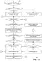
- FIGS. 4 A- 4 Bcomprise a flow chart illustrating one exemplary embodiment of a method 400 of dynamically managing a simulcast zone for a UE in a C-RAN.
- the embodiment of method 400 shown in FIGS. 4 A- 4 Bis described here as being implemented in the C-RAN system 100 of FIG. 1 , though it is to be understood that other embodiments can be implemented in other ways.
- FIGS. 4 A- 4 Bhave been arranged in a generally sequential manner for ease of explanation; however, it is to be understood that this arrangement is merely exemplary, and it should be recognized that the processing associated with method 400 (and the blocks shown in FIGS. 4 A- 4 B ) can occur in a different order (for example, where at least some of the processing associated with the blocks is performed in parallel and/or in an event-driven manner).
- Method 400is described here as being performed for each UE 110 that is connected to the cell 103 .
- the particular UE 110 for which method 400 is being performedis referred to here as the “current” UE 110 .
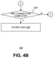
- the most recent cQSVis stored for possible use with the UE's next RRC connection.
- the serving controller 104When the current UE 110 establishes a new RRC connection to the cell 103 (block 402 shown in FIG. 4 A ) and the serving controller 104 has determined that there is a stored SV for the current UE 110 and there is a sufficient match between the stored SV and the PRACH metric determined for the new RRC connection (block 404 ), the cQSV for the current UE 110 is initialized using the stored cQSV for the current UE 110 (block 406 ). Otherwise, the cQSV is initialized without using a stored cQSV for the current UE 110 (block 408 ).
- the cQSVis initialized as follows.
- a first candidate QSV (QSV1)which has a corresponding candidate simulcast zone, is found that satisfies the following conditions.
- no RP j in the candidate simulcast zone associated with QSV1has a L sum (j)>Init_Load-Thr, where L sum (j) is the cumulative load (based on a sliding window) associated with the processing at RP j of all Resource Block Units (RBUs) allocated to all UEs 110 that have that RP j in their simulcast zone, and Init_Load-Thr is a configurable load threshold.
- L sum (j)is the cumulative load (based on a sliding window) associated with the processing at RP j of all Resource Block Units (RBUs) allocated to all UEs 110 that have that RP j in their simulcast zone
- Init_Load-Thris a configurable load threshold.
- the cQSVis initialized as follows.
- a first candidate QSV (QSV1)which has a corresponding a candidate simulcast zone, is found that satisfies the following conditions.
- minQSV ⁇ QSV1 ⁇ maxQSVwhere, in this case, “QSV1” represents the number of RPs 106 in the simulcast zone associated with QSV1.
- no RPj in the simulcast zone associated with QSV1has a L sum (j)>Init_Load-Thr.
- Method 400further comprises, after initialization of the cQSV, determining when to update the cQSV for the current UE 110 (block 410 ).
- the cQSV for the current UE 110is updated periodically using a period P cqsv that is determined as the following ratio: Rank Report Period/NumQSVOppPerRankRep, where Rank Report Period is the period used by UEs 110 in reporting their Rank Indication (RI) to the serving controller 104 (in milliseconds) and NumQSVOppPerRankRep is a configurable parameter indicating the number of opportunities to update the cQSV for each Rank Report Period (for example, this can be set to an integer of 1, 2, or 4). In one example, default values of 160 milliseconds and 2, respectively, can be used for Rank Report Period and NumQSVOppPerRankRep, and the minimum allowed value for the period P cqsv is 40 milliseconds.
- the UE's first cQSV update opportunity for a given RRC connectionoccurs as early as possible subject to the following conditions:
- the first conditionis that the first cQSV update opportunity will not occur before the SV and cQSV are initialized. More specifically, when SV and cQSV have not yet been not initialized upon S-TMSI retrieval, the first cQSV update opportunity will not occur until after the first SRS transmission from the current UE 110 has been received.
- the second conditionis that, after the current UE's cQSV has been initialized, the current UE's first CQI report following a rank report will always coincide with a cQSV update opportunity, such that there is never a rank change between two cQSV update opportunities.
- Method 400further comprises, when it is determined that the current UE's cQSV should be updated, checking whether the cQSV for the current UE 110 is currently admissible (block 412 ) and, if the cQSV for the current UE 110 is determined to be inadmissible, modifying the cQSV for the current UE 110 to be admissible (block 414 ). If the cQSV is modified at this point, the forced expansion flag for the current UE 110 (described below) is cleared (block 416 ), the related metrics are updated (block 418 ), and the processing for the current cQSV update opportunity is complete.
- J candidate QSVswhere the j-th candidate QSV, QSV j , is the one having a simulcast zone containing the j RPs 106 with the best signal reception metric as reflected in the most-recent SV for the current UE 110 .
- jmin and jmaxrepresent values for the index j of the candidate cQSV associated with the current UE's minQSV and maxQSV, respectively.
- the candidate QSV based on the most-recent SV having an index jminhas a simulcast zone containing a number of RPs 106 equal to the minQSV for the current UE 110 .
- This candidate QSVis also referred to here simply as the “minQSV” in the context of discussing particular candidate QSVs.
- the candidate QSV based on the most-recent SV having an index jmaxhas a simulcast zone containing a number of RPs 106 equal to the maxQSV for the current UE 110 .
- This candidate QSVis also referred to here simply as the “maxQSV” in the context of discussing particular candidate QSVs.
- the set of admissible candidate QSVs for the current UE 110comprises the candidate QSVs ⁇ jmin, . . . , jmax ⁇ .
- a cQSVis deemed admissible if, based on the most-recent SV for the current UE 110 , it is included in this set of admissible candidate QSVs for the current UE 110 and is deemed inadmissible if this is not the case.
- the current UE's cQSVremains admissible (and is not changed at this point) even if the ordering of the RPs 106 in the most-recent SV has changed since the last cQSV-update opportunity, as long as the cQSV is still included in the set of admissible candidate QSVs based on the most-recent SV.
- the cQSV for the current UE 110is set to the maxQSV for the current UE 110 .
- Method 400further comprises, if the cQSV for the current UE 110 is determined to be admissible, updating load calculations for any changes in minQSV for the current UE 110 (block 420 ).
- the minQSVis updated and changed from time to time.
- the load calculations for those RPs 106 that are affected by the change in the minQSVare updated.
- the load calculation for each of those RPs 106is increased by the additional load associated with the current UE 110 , and if the current UE's minQSV has changed by removing one or more RPs 106 from the simulcast zone associated with the minQSV, the load calculation for each of those RPs 106 is decreased by the load associated with the current UE 110 .
- Method 400further comprises checking if the cQSV for the current UE 110 should be forced to expand (block 422 ). If that is the case, a forced expansion of the cQSV for the current UE 110 is performed (block 424 ).
- a flagalso referred to here as the “force expansion flag”
- a configurable parameterindicates by how many RPs 106 the minQSV is expanded when a forced expansion is performed.
- the forced expansion flag for the current UE 110is cleared (block 416 ), the related metrics are updated (block 418 ), and the processing for the current cQSV update opportunity is complete.
- the SINR actually experienced in the channel for the current UE 110may be much lower than the estimated SINR, due to, for example, inaccuracies in SRS measurements and, as a result, the resulting SV.
- the UE's cQSV simulcast zone in such circumstancesmay not contain all the RPs 106 it should to provide a sufficiently high SIR.
- the current UE 110may experience a high block error ratio (BLER) or be provided throughput much lower than desired.
- BLERblock error ratio
- the cQSV for the current UE 110can be flagged for a forced expansion.
- such a situationcan be identified (and the current UE 110 flagged for a forced expansion) if one of the following occurs: the current UE 110 receives two consecutive negative acknowledgments (NACKs) for third retransmissions, the current UE 110 receives two consecutive NACKs for first transmissions made using a power level below a configurable floor, or the current UE 110 receives two consecutive NACKs for first transmissions made using a MCS of 0.
- NACKsnegative acknowledgments
- the cQSV for the current UE 110may not be contracted after a forced expansion for a configurable hysteresis period of time after the forced expansion is performed. In such an implementation, the processing associated with determining if the cQSV for the current UE 110 should be contracted is skipped until the configurable hysteresis period has elapsed after the forced expansion.
- Method 400further comprises, if the cQSV for the current UE 110 should not be forced to expand, determining if the current UE 110 has a valid RateRatio (checked in block 426 ). If that is the case, a contraction eligibility metric and an expansion eligibility metric for the cQSV of the current UE 110 are computed (block 428 ) and the eligibility of the current UE 110 for contraction and expansion of its cQSV is tested (block 430 ). Then, if indicated by the testing, the cQSV for the current UE 110 is changed as indicated (block 432 ) and the related metrics are updated (block 418 ) and the processing for the current cQSV update opportunity is complete. Otherwise, method 400 proceeds to block 434 (which is described below).
- an estimate of the ratio between a connected UE's actual achieved rate and its average virtual CQI rateis calculated for the current UE 110 .
- a UE's actual achieved ratereflects the effect of reuse interference, whereas the average virtual CQI rate represents the achievable rate without reuse interference.
- a higher ratioindicates a lower amount of reuse interference, whereas a lower ratio indicates a higher amount of reuse interference.
- This estimated ratiois also referred to here as the “RateRatio.”
- each RP jone UE 110 that has that RP j in its cQSV is identified as the UE 110 most eligible for contraction for that RP j .
- a contraction eligibility metric threshold and UE identifierare maintained for each RP j of the cell 103 , where the UE identifier is an identifier associated with the UE 110 that is most eligible for contraction (for example, the RNTI of that UE 110 ) and the contraction eligibility metric threshold is the most recent value of the contraction eligibility metric for that most-eligible UE 110 .
- the contraction eligibility metric for the current UE 110is computed by estimating the change in total airlink throughput after the contraction of the cQSV of the current UE 110 by removing various numbers of the outermost RPs 106 from the current UE's cQSV. Then, the maximum estimated change in the throughput and processing load, as well as the maximum contraction demand (described in below), are found for the various RPs 106 that are candidates for contraction.
- the contraction eligibility metric for the current UE 110is determined based on the maximum estimated change in total airlink throughput, the maximum estimated change in the processing load, the maximum contraction demand, and the RateRatio for the current UE 110 .
- any resulting contraction of the cQSV for the current UE 110is limited to only to the outermost RP 106 in the cQSV.
- a number of “outermost” RPs 106 of a cQSVrefers to that number of RPs 106 in the cQSV that have the lowest signal reception metrics in the most-recent SV.
- this computationis subject to the minQSV. That is, the current UE's cQSV is not eligible to be contracted below its minQSV.
- the eligibility of the current UE 110 for contraction of its cQSVis tested by first checking the outermost RP 106 for the current UE's cQSV to see if the current UE 110 is the one most-eligible for contraction for that RP 106 . This is determined by comparing the identifier of the current UE 110 to the identifier of the most eligible UE 110 for that outermost RP 106 . If they do not match, then the computed contraction eligibility metric for the current UE 110 is compared with the contraction eligibility metric threshold for the outermost RP 106 in the current UE's cQSV.
- the current UE 110becomes the one that is most eligible for contraction for that outermost RP 106 and the contraction eligibility metric threshold for that outermost RP 106 is updated to be the computed contraction eligibility metric for the current UE 110 . Otherwise, there is no change.
- the computed contraction eligibility metric for the current UE 110is compared to the contraction eligibility metric threshold for that outermost RP 106 to see if the computed contraction eligibility metric for the current UE 110 is greater than or equal to configurable percentage of the contraction eligibility metric threshold for that outermost RP 106 and if the computed contraction eligibility metric for the current UE 110 is greater than a configurable minimum margin value.
- the current UE 110is flagged for contraction and the contraction eligibility metric threshold and most-eligible UE 110 for contraction for the outermost RP 106 are both cleared. Otherwise, the contraction eligibility metric threshold for the outermost RP 106 is updated to be set to the computed contraction eligibility metric for the current UE 110 .
- each RP jone of the UE's 110 that has that RP j in its cQSV is identified as the UE 110 that is most eligible for expansion.
- an expansion eligibility metric threshold and UE identifieris maintained for each RP j of the cell 103 , where the UE identifier is an identifier associated with the UE 110 that is most eligible for expansion (for example, the RNTI of that UE 110 ) and the expansion eligibility metric threshold is the most recent value of the expansion eligibility metric for that most-eligible UE 110 .
- the expansion eligibility metric for the current UE 110is computed by estimating the change in total airlink throughput after the expansion of the cQSV of the current UE 110 by various numbers of the next potential RPs 106 that are not currently in the current UE's cQSV. Then, the maximum estimated change in the throughput and processing load, as well as the maximum contraction demand (described in below), are found for the various RPs 106 that are candidates for expansion.
- the expansion eligibility metric for the current UE 110is determined based on the maximum estimated change in total airlink throughput, the maximum estimated change in the processing load, the maximum contraction demand, and the RateRatio for the current UE 110 . This computation is subject to the maxQSV. That is, the current UE's cQSV is not eligible to be expanded above its maxQSV.
- any resulting expansion of the cQSVis limited to only the next potential RP 106 that is not in the current UE's cQSV.
- a number of “next potential” RPs 106 for a cQSVrefers to that number of RPs 106 that are not in the cQSV that have the highest signal reception metrics in the most-recent SV.
- the eligibility of the current UE 110 for expansion of its cQSVis tested by first checking the next potential RP 106 for the current UE's cQSV to see if the current UE 110 is the one that is the most-eligible for expansion for the next potential RP 106 . This is determined by comparing the identifier of the current UE 110 to the identifier of the UE 110 that is most-eligible for expansion for the next potential RP 106 . If they do not match, then the computed expansion eligibility metric for the current UE 110 is compared with the expansion eligibility metric threshold for the next potential RP 106 in the current UE's cQSV.
- the current UE 110is set to be the one most eligible for expansion for that RP 106 and the expansion eligibility metric threshold for that RP 106 is updated to be the computed expansion eligibility metric for the current UE 110 . Otherwise, there is no change.
- the computed expansion eligibility metric for the current UE 110is compared to the expansion eligibility metric threshold for that next potential RP 106 to see if the computed expansion eligibility metric for the current UE 110 is greater than or equal to a configurable percentage of the expansion eligibility metric threshold for that RP 106 and if the computed expansion eligibility metric for the current UE 110 is greater than a configurable minimum margin value.
- the current UE 110is flagged for expansion and the expansion eligibility metric threshold and most-eligible UE 110 for expansion for the next potential RP 106 are both cleared. Otherwise, the expansion eligibility metric threshold for the next potential RP 106 is updated to be set to the computed expansion eligibility metric for the current UE 110 .
- the contraction and expansion eligibility metrics for the current UE 110are computed, if the current UE's cQSV is flagged for contraction but not for expansion, the current UE's cQSV is contracted from its outermost RP 106 .
- the current UE's cQSVis expanded into its next potential RP 106 .
- the computed contraction and expansion eligibility metricsare compared. If the contraction eligibility metric is greater than the expansion eligibility metric plus a configurable margin, the current UE's cQSV is contracted from its outermost RP 106 . If the expansion eligibility metric is greater than the contraction eligibility metric plus a configurable margin, the current UE's cQSV is expanded into its next potential RP 106 . Otherwise, the current UE's cQSV is not changed.
- the current UE's cQSVis not flagged for contraction or for expansion, the current UE's cQSV is not changed.
- the cQSV for the current UE 110may not be contracted for a configurable hysteresis period of time after a forced expansion has occurred.
- the processing described above for determining if the cQSV for the current UE 110 should be contractedis skipped until the configurable hysteresis period has elapsed after a forced expansion has occurred.
- Method 400further comprises updating the contraction demand for the RPs 106 in the current UE's minQSV (block 434 ). After this is done, the various metrics are updated (block 418 ) and the processing for the current cQSV update opportunity is complete.
- the “expanded RPs” 106 for a given UE 110are those RPs 106 that are in the UE's cQSV but not in the UE's minQSV, and the “minQSV RPs” 106 for a given UE 110 are those RPs 106 that are in the UE's minQSV. Also, as used here, a UE 110 has “expanded onto” a RP 106 if the UE 110 has expanded its cQSV beyond its minQSV to include that RP 106 , which is not in the UE's minQSV.
- a “contraction demand”refers to a metric indicative of the backlog for a UE 110 experienced at the UE's minQSV RPs 106 .
- the contraction demandis indicative of the maximum number of resource block units (RBUs) the UE 110 could utilize at the UE's minQSV RPs 106 if all other UEs 110 that have expanded onto those RPs 106 contracted their cQSVs to no longer include those RPs 106 .
- the contraction demandis used to determine if other UEs 110 that have expanded onto those RPs 106 should contract their cQSVs in order to remove those RPs 106 from their cQSVs.
- the following variablesare maintained for each RP 106 serving the cell 103 : a contraction demand variable, a UE identifier variable, a rate variable, and an expiry timer variable.
- the UE identifier variableis used to identify the UE 110 that includes that RP 106 in its minQSV that is experiencing the heaviest backlog. This identifier can be, for example, the RNTI of the UE 110 .
- the contraction demand variableis used to store the contraction demand metric for the identified UE 110 .
- the rate variableis used to store the estimated actual achieved rate for the identified UE 110 .
- the expiry timer variableis used to indicate when the other variables should expire and no longer be used.
- the backlog experienced by the current UE 110 at its minQSV RPs 106is checked to see if it is greater that a configurable backlog threshold. If it is, the contraction demand metric for the current UE 110 is updated and then each of the current UE's minQSV RPs 106 is checked.
- the variables maintained for that RP 106are updated with the current UE's identifier, contraction demand metric, and estimated actual achieved rate, and the expiry timer variable for that RP 106 is reset.
- the variables maintained for that RP 106are updated with the current UE's contraction demand metric and estimated actual achieved rate, and the expiry timer variable for that RP 106 is reset.
- the contraction demand for the current UE 110will be taken into account during the contraction and expansion calculations of other UEs 110 and will influence the contraction and expansion of the cQSVs of the other UEs 110 .
- the cQSV for the current UE 110is stored for possible later retrieval and use as described above (block 438 ).
- the various techniques described abovecan be used to more effectively manage the simulcast zone used for transmitting to each UE connected to a cell provided by a C-RAN.
- FIGS. 5 A- 5 Bcomprise a flow chart illustrating one exemplary embodiment of a method 500 of dynamically managing a link adaptation variable used to initialize and dynamically update the modulation and coding scheme (MCS) used to communicate with a UE in a C-RAN.
- MCSmodulation and coding scheme
- FIGS. 5 A- 5 Bhave been arranged in a generally sequential manner for ease of explanation; however, it is to be understood that this arrangement is merely exemplary, and it should be recognized that the processing associated with method 500 (and the blocks shown in FIGS. 5 A- 5 B ) can occur in a different order (for example, where at least some of the processing associated with the blocks is performed in parallel and/or in an event-driven manner).
- Method 500is described here as being performed for each UE 110 that is connected to the cell 103 .
- the particular UE 110 for which method 500 is being performedis referred to here as the “current” UE 110 .
- the MCS for each UE 110is determined using an estimate of the SINR (SINR EST ) for that UE 110 .
- the link adaptation processis initialized and the link adaptation variable ⁇ dB for each code word is initialized (for example, to 0) (block 504 ).
- the link adaptation variables ⁇ dBare updated each time there is a HARQ transmission received for the current UE 110 (checked in block 506 ).
- the controller 104instantiates a flag (Stale UE flag) for each code word and associated link adaptation variable ⁇ dB .
- Stale UE flagis used to determine when the associated link adaptation variable ⁇ dB is stale and should be reset.
- the link adaptation variable ⁇ dB for the associated code wordis reset (for example, to 0) (block 510 ) and the associated Stale UE flag is cleared (block 512 ).
- the link adaptation variable ⁇ dBis reset on a conditional basis—for example, only if the link adaptation variable ⁇ dB is positive.
- the associated Stale UE flagis set (block 516 ), which causes the associated link adaptation variable ⁇ dB to be reset at the next HARQ transmission.
- the Stale UE flags for the associated code wordsare set (block 516 ), which causes the associated link adaptation variables ⁇ dB to be reset at the next HARQ transmission.
- the link adaptation variable ⁇ dB for each code wordis not reset upon a change in the cQSV for the corresponding UE 100 or solely in response to a PMI change.
- the associated link adaptation variables ⁇ dBare not reset, the associated link adaptation variables ⁇ dB are updated based on whether a HARQ ACK or NACK message is received.
- ⁇ ACKa configurable amount
- ⁇ NACKa second configurable amount
- ⁇ ACKis set to 0.1 dB
- ⁇ NACKis set to 0.9 db.
- ⁇ ACK and ⁇ NACKcan be updated dynamically.
- the associated link adaptation variables ⁇ dBare adjusted (block 528 ) upon updating of the SINR EST0 for the current UE 110 (for example, to reflect a change in CQI or SIRPL) (block 526 ).
- the amount of adjustmentdepends, in this embodiment, on the number of HARQ ACK or NACK based updates that have been made since the last adjustment.
- each adjusted link adaptation variable ⁇ dB_newthat link adaptation variable before adjustment ⁇ dB_old +f*X, where:
- Xthe SINR EST0 for the link adaptation variable before adjustment ⁇ dB_old minus the SINR EST0 for the adjusted link adaptation variable ⁇ dB_adjusted ;
- fthe minimum of (a) the number of ACK/NACK based updates that have been made since the last adjustment divided by a configurable maximum number of ACK/NACK based updates that have been made since the last adjustment; or (b) 1.
- no rank overrideis used (even when there is little buffered data to transmit).
- the dynamic cQSV scheme that is usedcan be designed to minimize the conditions where a rank override may be necessary. If retransmission is required, the same transport format as the initial transmission is used, regardless of the prevailing rank at the time of retransmission.
- the methods and techniques described heremay be implemented in digital electronic circuitry, or with a programmable processor (for example, a special-purpose processor or a general-purpose processor such as a computer) firmware, software, or in combinations of them.
- Apparatus embodying these techniquesmay include appropriate input and output devices, a programmable processor, and a storage medium tangibly embodying program instructions for execution by the programmable processor.
- a process embodying these techniquesmay be performed by a programmable processor executing a program of instructions to perform desired functions by operating on input data and generating appropriate output.
- the techniquesmay advantageously be implemented in one or more programs that are executable on a programmable system including at least one programmable processor coupled to receive data and instructions from, and to transmit data and instructions to, a data storage system, at least one input device, and at least one output device.
- a processorwill receive instructions and data from a read-only memory and/or a random access memory.
- Storage devices suitable for tangibly embodying computer program instructions and datainclude all forms of non-volatile memory, including by way of example semiconductor memory devices, such as EPROM, EEPROM, and flash memory devices; magnetic disks such as internal hard disks and removable disks; magneto-optical disks; and DVD disks. Any of the foregoing may be supplemented by, or incorporated in, specially-designed application-specific integrated circuits (ASICs).
- ASICsapplication-specific integrated circuits
- Example 1includes a system to provide wireless service comprising: a controller; and a plurality of radio points; wherein each of the radio points is associated with at least one antenna and remotely located from the controller, wherein the plurality of radio points is communicatively coupled to the controller; wherein the controller and the plurality of radio points are configured to implement a base station in order to provide wireless service to a plurality of user equipment (UEs) using a cell; wherein the controller is communicatively coupled to a core network of a wireless service provider; wherein the system is configured to transmit at least some data to each UE connected to the cell using a respective subset of the radio points; wherein the system is configured to determine the respective subset of the radio points for transmitting to each UE connected to the cell using a signature vector comprising a set of signal reception metrics, each signal reception metric associated with a respective one of the radio points and indicative of the reception of a signal transmitted from the respective UE at one of the radio points; and wherein the system is configured to do the following when each UE
- Example 2includes the system of Example 1, wherein the system is configured to store the signature vector associated with each UE connected to the cell when each connection that UE establishes with the cell is completed.
- Example 3includes the system of any of the Examples 1-2, wherein the system is configured to determine the initial signal reception metrics for each UE connected to the cell based on a LTE Physical Random Access Channel (PRACH) transmission from that UE.
- PRACHPhysical Random Access Channel
- Example 4includes the system of any of the Examples 1-3, wherein the system is configured to update the signature vector for each UE connected to the cell based on LTE Sounding Reference Signals (SRS) transmitted by that UE.
- SRSSounding Reference Signals
- Example 5includes the system of any of the Examples 1-4, wherein the controller is communicatively coupled to the radio points using a switched ETHERNET network.
- Example 6includes a system to provide wireless service comprising: a controller; and a plurality of radio points; wherein each of the radio points is associated with at least one antenna and remotely located from the controller, wherein the plurality of radio points is communicatively coupled to the controller; wherein the controller and the plurality of radio points are configured to implement a base station in order to provide wireless service to a plurality of user equipment (UEs) using a cell; wherein the controller is communicatively coupled to a core network of a wireless service provider; wherein the system is configured to do the following for each UE connected to the cell: determine a signature vector comprising a set of signal reception metrics, each signal reception metric associated with a respective one of the radio points and indicative of the reception of a signal transmitted from the respective UE at one of the radio points; determine a respective minimum subset of the radio points for transmitting to that UE; determine a respective maximum subset of the radio points for transmitting to that UE; and determine a respective current subset of the radio points for transmitting to
- Example 7includes the system of Example 6, wherein the system is configured to store the signature vector associated with each UE when each connection that UE establishes with the cell is completed; and wherein the system is configured to do the following when each UE establishes a new connection with the cell: determine initial signal reception metrics for that UE; and if the system has a stored signature vector associated with that UE and that stored signature vector matches the initial signal reception metrics for that UE, initialize the signature vector for that UE using that stored signature associated with that UE.
- Example 8includes the system of Example 7, wherein the system is configured to determine the initial signal reception metrics for each UE based on a LTE Physical Random Access Channel (PRACH) transmission from that UE.
- PRACHPhysical Random Access Channel
- Example 9includes the system of any of the Examples 6-8, wherein the system is configured to update the signature vector for each UE based on LTE Sounding Reference Signals (SRS) transmitted by that UE.
- SRSSounding Reference Signals
- Example 10includes the system of any of the Examples 6-9, wherein the system is configured to expand the number of radio points in the minimum subset of the radio points for each UE using a phased approach if the respective signature vector for that UE has not been updated at least a predetermined number of times.
- Example 11includes the system of any of the Examples 6-10, wherein the controller is communicatively coupled to the radio points using a switched ETHERNET network.
- Example 12includes the system of any of the Examples 6-11, wherein the system is configured to do the following for each UE connected to the cell: determine a modulation and coding scheme (MCS) to use with each code word used for communications with said UE as a function of an estimate of a signal-to-interference-plus-noise ratio (SINR) and a link adaptation variable associated with each code word; and dynamically update each link adaptation variable for said UE based on hybrid automatic repeat request (HARQ) acknowledgments (ACKs) and negative acknowledgements (NACKs) received for said UE and the associated code word.
- MCSmodulation and coding scheme
- SINRsignal-to-interference-plus-noise ratio
- HARQhybrid automatic repeat request
- ACKsacknowledgments
- NACKsnegative acknowledgements
- Example 13includes a system to provide wireless service comprising: a controller; and a plurality of radio points; wherein each of the radio points is associated with at least one antenna and remotely located from the controller, wherein the plurality of radio points is communicatively coupled to the controller; wherein the controller and the plurality of radio points are configured to implement a base station in order to provide wireless service to a plurality of user equipment (UEs) using a cell; wherein the controller is communicatively coupled to a core network of a wireless service provider; wherein the system is configured to do the following for each UE connected to the cell: determine a signature vector comprising a set of signal reception metrics, each signal reception metric associated with a respective one of the radio points and indicative of the reception at one of the radio points of a signal transmitted from the respective UE; determine a respective minimum subset of the radio points for transmitting to that UE; determine a respective maximum subset of the radio points for transmitting to that UE; and determine a respective current subset of the radio points for transmitting to
- Example 14includes the system of Example 13, wherein the system is configured to, for each UE connected to the cell, expand the number of radio points in the respective current subset of the radio points for that UE if that UE experiences issues receiving transmissions using the current subset of the radio points.
- Example 15includes the system of any of the Examples 13-14, wherein the system is configured to store the current subset of the radio points for each UE when each connection that UE establishes with the cell is completed; and wherein the system is configured to, when each UE establishes a new connection with the cell, initialize the current subset of the radio points for that UE if there is a stored current subset of the radio points for that UE and if certain conditions are met.
- Example 16includes the system of any of the Examples 13-15, wherein the system is configured to, for each UE connected to the cell, expand the number of radio points in the minimum subset of the radio points if the respective signature vector for that UE has not been updated at least a predetermined number of times.
- Example 17includes the system of any of the Examples 13-16, wherein the system is configured to determine the initial signal reception metrics for each UE based on a LTE Physical Random Access Channel (PRACH) transmission from that UE.
- PRACHPhysical Random Access Channel
- Example 18includes the system of any of the Examples 13-17, wherein the system is configured to update the signature vector for each UE based on LTE Sounding Reference Signals (SRS) transmitted by that UE.
- SRSSounding Reference Signals
- Example 19includes the system of any of the Examples 13-18, wherein the controller is communicatively coupled to the radio points using a switched ETHERNET network.
- Example 20includes the system of any of the Examples 13-19, wherein the system is configured to do the following for each UE connected to the cell: determine a modulation and coding scheme (MCS) to use with each code word used for communications with said UE as a function of an estimate of a signal-to-interference-plus-noise ratio (SINR) and a link adaptation variable associated with that code word; and dynamically update each link adaptation variable for said UE based on hybrid automatic repeat request (HARQ) acknowledgments (ACKs) and negative acknowledgements (NACKs) received for said UE and the associated code word.
- MCSmodulation and coding scheme
- SINRsignal-to-interference-plus-noise ratio
- HARQhybrid automatic repeat request
- ACKsacknowledgments
- NACKsnegative acknowledgements
Landscapes
- Engineering & Computer Science (AREA)
- Signal Processing (AREA)
- Computer Networks & Wireless Communication (AREA)
- Quality & Reliability (AREA)
- Mobile Radio Communication Systems (AREA)
Abstract
Description
- The elapsed time since the last update of the stored SV during the current UE's previous RRC connection is less than a configurable setting (referred to here as “StoredSvMaxAge”);
- The PRACH transmission is detected by the
primary RP 106 of the stored SV (for example, the PRACH signal reception metric for theprimary RP 106 is above a predetermined threshold); - The PRACH transmission is detected by the
RP 106 having the next best reception metric in the stored SV (the “second” RP106), if the difference between the reception metric for theprimary RP 106 and the reception metric for thesecond RP 106 is less than a configurable value (referred to here as “deltaSvForPrachMatch”); and - When at least two
RPs 106 detect the PRACH transmission, the twoRPs 106 with the highest PRACH reception metric must be among theRPs 106 having the top three reception metrics in the stored SV.
New SV=Stored SV*(1−min(Δt/(StoredSvMaxAge+ΔTinit),1))+SRS SV*Δt/(StoredSvMaxAge+ΔTinit)
avgSV_tilde=[s_tilde(1), . . . ,s_tilde(Nrp)],
- variance([s(k_hat) . . . s(Nrp)])<=VarianceThreshold
- variance([s(k_hat−1) . . . s(Nrp)])>VarianceThreshold
Claims (21)
Priority Applications (2)
| Application Number | Priority Date | Filing Date | Title |
|---|---|---|---|
| US16/149,294US11678358B2 (en) | 2017-10-03 | 2018-10-02 | Dynamic downlink reuse in a C-RAN |
| US18/309,139US12426075B2 (en) | 2017-10-03 | 2023-04-28 | Dynamic downlink reuse in a C-RAN |
Applications Claiming Priority (2)
| Application Number | Priority Date | Filing Date | Title |
|---|---|---|---|
| US201762567658P | 2017-10-03 | 2017-10-03 | |
| US16/149,294US11678358B2 (en) | 2017-10-03 | 2018-10-02 | Dynamic downlink reuse in a C-RAN |
Related Child Applications (1)
| Application Number | Title | Priority Date | Filing Date |
|---|---|---|---|
| US18/309,139ContinuationUS12426075B2 (en) | 2017-10-03 | 2023-04-28 | Dynamic downlink reuse in a C-RAN |
Publications (2)
| Publication Number | Publication Date |
|---|---|
| US20190104527A1 US20190104527A1 (en) | 2019-04-04 |
| US11678358B2true US11678358B2 (en) | 2023-06-13 |
Family
ID=65897065
Family Applications (2)
| Application Number | Title | Priority Date | Filing Date |
|---|---|---|---|
| US16/149,294ActiveUS11678358B2 (en) | 2017-10-03 | 2018-10-02 | Dynamic downlink reuse in a C-RAN |
| US18/309,139ActiveUS12426075B2 (en) | 2017-10-03 | 2023-04-28 | Dynamic downlink reuse in a C-RAN |
Family Applications After (1)
| Application Number | Title | Priority Date | Filing Date |
|---|---|---|---|
| US18/309,139ActiveUS12426075B2 (en) | 2017-10-03 | 2023-04-28 | Dynamic downlink reuse in a C-RAN |
Country Status (4)
| Country | Link |
|---|---|
| US (2) | US11678358B2 (en) |
| EP (1) | EP3692735B1 (en) |
| CN (2) | CN116318589A (en) |
| WO (1) | WO2019070627A1 (en) |
Families Citing this family (7)
| Publication number | Priority date | Publication date | Assignee | Title |
|---|---|---|---|---|
| US9414399B2 (en) | 2013-02-07 | 2016-08-09 | Commscope Technologies Llc | Radio access networks |
| WO2015191530A2 (en) | 2014-06-09 | 2015-12-17 | Airvana Lp | Radio access networks |
| US11678358B2 (en) | 2017-10-03 | 2023-06-13 | Commscope Technologies Llc | Dynamic downlink reuse in a C-RAN |
| US11304213B2 (en) | 2018-05-16 | 2022-04-12 | Commscope Technologies Llc | Dynamic uplink reuse in a C-RAN |
| US11159377B2 (en)* | 2018-09-13 | 2021-10-26 | Commscope Technologies Llc | Front-haul plug-and-play configuration for a C-RAN |
| US11388618B2 (en) | 2019-06-06 | 2022-07-12 | Commscope Technologies Llc | Distributed radio access network implementing fronthaul operational measurements |
| WO2021126469A1 (en)* | 2019-12-19 | 2021-06-24 | Commscope Technologiesllc | Automatic configuration of operational parameters in small cells without using radio environment monitoring |
Citations (275)
| Publication number | Priority date | Publication date | Assignee | Title |
|---|---|---|---|---|
| EP1134935A2 (en) | 2000-03-17 | 2001-09-19 | Symbol Technologies, Inc. | Wireless local area network with plural RF ports |
| US20020128009A1 (en) | 2001-02-20 | 2002-09-12 | Erik Boch | Transceiver for fixed wireless access network applications |
| US20020154055A1 (en) | 2001-04-18 | 2002-10-24 | Robert Davis | LAN based satellite antenna/satellite multiswitch |
| US20020194605A1 (en) | 2001-05-18 | 2002-12-19 | T.M.T. Third Millenium Technologies Ltd. | Cableran networking over coaxial cables |
| US6711144B1 (en) | 2000-09-15 | 2004-03-23 | Airvana, Inc. | Multi-user communication of voice and data |
| US6731618B1 (en) | 2000-10-20 | 2004-05-04 | Airvana, Inc. | Coding for multi-user communication |
| US6741862B2 (en) | 2001-02-07 | 2004-05-25 | Airvana, Inc. | Enhanced reverse-link rate control in wireless communication |
| US20040136373A1 (en) | 2003-01-13 | 2004-07-15 | Bareis Bernard F. | Broadband multi-drop local network, interface and method for multimedia access |
| US20040143442A1 (en) | 2003-01-22 | 2004-07-22 | Knight Erik A. | Multiple-language audio information transmission system and device |
| US20040146072A1 (en) | 2001-09-13 | 2004-07-29 | Pedestal Networks Incorporated | System for enhancing data transfer |
| US6781999B2 (en) | 2001-07-23 | 2004-08-24 | Airvana, Inc. | Broadcasting and multicasting in wireless communication |
| US20040224637A1 (en) | 2002-11-04 | 2004-11-11 | Silva Marcus Da | Directed wireless communication |
| US20050025160A1 (en) | 2000-11-22 | 2005-02-03 | Cisco Technology, Inc. | System and method for grouping multiple VLANs into a single 802.11 IP multicast domain |
| US20050073964A1 (en) | 2003-07-24 | 2005-04-07 | 3E Technologies International, Inc. | Method and system for fast setup of group voice over IP communications |
| US6882847B2 (en) | 2000-06-15 | 2005-04-19 | Telefonaktiebolaget Lm Ericsson (Publ) | Fractional reuse through channel allocation tiering |
| US20050157675A1 (en) | 2004-01-16 | 2005-07-21 | Feder Peretz M. | Method and apparatus for cellular communication over data networks |
| US6985451B1 (en) | 1997-10-14 | 2006-01-10 | Alvarion Israel (2003) Ltd. | Method and apparatus for baseband transmission between a top floor unit and an outdoor unit in a terminal for a wireless metropolitan area network |
| CN1719929A (en) | 2004-07-10 | 2006-01-11 | 三星电子株式会社 | Resource allocation method for downlink transmission in code division multiple access communication system |
| US20060056559A1 (en) | 2004-09-13 | 2006-03-16 | Pleasant Daniel L | System and method for coordinating the actions of a plurality of devices via scheduling the actions based on synchronized local clocks |
| US20060056459A1 (en) | 2004-09-13 | 2006-03-16 | Stratton John B | Add-on module for synchronizing operations of a plurality of devices |
| US20060209752A1 (en) | 2004-01-16 | 2006-09-21 | Wijngaarden Adriaan Jeroen D L | Method and apparatus for cellular communication over data networks |
| US7170871B2 (en) | 2001-06-25 | 2007-01-30 | Airvana, Inc. | Radio network control |
| US20070023419A1 (en) | 2004-03-10 | 2007-02-01 | Watlow Electric Manufacturing Company | Variable watt density layered heater |
| US20070058683A1 (en) | 2005-09-15 | 2007-03-15 | Fujitsu Limited | Mobile communication system, and base transceiver station apparatus and mobile station apparatus used in mobile communication system |
| US7200391B2 (en) | 2002-12-06 | 2007-04-03 | Airvana, Inc. | Capacity enhancement schemes for forward and reverse links of distributed cellular base stations |
| US20070086487A1 (en) | 2005-09-28 | 2007-04-19 | Takeshi Yasuda | Communication system, master communication device, and slave communication device |
| US20070140218A1 (en) | 2005-12-16 | 2007-06-21 | Nair Girish R | Managing backhaul connections in radio access networks |
| US7242958B2 (en) | 2001-10-12 | 2007-07-10 | Airvana, Inc. | Boosting a signal-to-interference ratio of a mobile station |
| US7260077B2 (en)* | 2001-06-18 | 2007-08-21 | Nortel Networks Limited | Adaptive scheduling for multi-carrier systems |
| US20070207838A1 (en) | 2006-03-06 | 2007-09-06 | Hitachi Ltd. | Radio communication method and radio base transmission station |
| US20070220573A1 (en) | 2006-03-20 | 2007-09-20 | Chiussi Fabio M | Unicasting and multicasting multimedia services |
| US7277446B1 (en) | 2000-11-02 | 2007-10-02 | Airvana, Inc. | Communication of digital data over a wireless transmission medium |
| US20070230419A1 (en) | 2006-03-31 | 2007-10-04 | Sundar Raman | QoS signaling to support fairness |
| US20070242648A1 (en) | 2006-04-12 | 2007-10-18 | Deepak Garg | Managing dormant handoffs in radio access networks |
| US7299278B2 (en) | 2002-01-16 | 2007-11-20 | Airvana, Inc. | Managing network faults |
| US20070297412A1 (en) | 2006-06-21 | 2007-12-27 | Huawei Technologies Co., Ltd. | Method and apparatus for forwarding data in forwarding networks |
| US20080003988A1 (en) | 2004-07-30 | 2008-01-03 | Andrew Richardson | Local Network Node |
| CN101106766A (en) | 2007-07-18 | 2008-01-16 | 华为技术有限公司 | Distributed base station, indoor unit and outdoor unit of distributed base station |
| US20080137606A1 (en) | 2006-12-04 | 2008-06-12 | Interdigital Technology Corporation | Method and apparatus of enabling multi band transmission |
| US20080165883A1 (en)* | 2005-09-30 | 2008-07-10 | Huawei Technologies Co., Ltd. | Resource allocation method for mimo-ofdm of multi-user access systems |
| US7415242B1 (en) | 2003-11-10 | 2008-08-19 | Sprint Spectrum L.P. | Method and system for proximity detection for an in-building wireless repeater |
| US20080200202A1 (en) | 2007-02-13 | 2008-08-21 | Qualcomm Incorporated | Power control with link imbalance on downlink and uplink |
| US20080233886A1 (en) | 2007-03-20 | 2008-09-25 | Alcatel Lucent | Method for scheduling of service data in downlink, a base station, a user terminal and a communication network therefor |
| US20080240034A1 (en) | 2007-03-19 | 2008-10-02 | Sridhar Gollamudi | Methods for frequency-selective persistent scheduling |
| WO2008144363A2 (en) | 2007-05-18 | 2008-11-27 | Qualcomm Incorporated | Pilot structures for ack and cqi in a wireless communication system |
| US7515643B2 (en) | 2004-09-30 | 2009-04-07 | Airvana, Inc. | Modulation for broadcasting from multiple transmitters |
| US20090097444A1 (en) | 2006-03-07 | 2009-04-16 | Matsushita Electric Industrial Co., Ltd. | Overhead reduction of uplink control signaling in a mobile communication system |
| US20090135718A1 (en) | 2006-03-22 | 2009-05-28 | Electronics And Telecommunications Research Institute | Method for retransmission in mobile communication system |
| US20090149221A1 (en) | 2004-09-08 | 2009-06-11 | Utstarcom Telecom Co., Ltd. | Centralized base station system based on advanced telecommunication computer architecture platform |
| US7558356B2 (en) | 2004-09-30 | 2009-07-07 | Airvana, Inc. | Providing global positioning system (GPS) timing signals to remote cellular base stations |
| US7558588B2 (en) | 2005-11-18 | 2009-07-07 | Airvana, Inc. | Resource allocation in a radio access network |
| US20090180423A1 (en) | 2005-07-13 | 2009-07-16 | Nokia Siemens Networks Gmbh & Co. Kg | Transmission of Ethernet Packets Via CPRI Interface |
| US20090180435A1 (en) | 2008-01-07 | 2009-07-16 | Qualcomm Incorporated | Tdd operation in wireless communication systems |
| CN101534507A (en) | 2008-03-12 | 2009-09-16 | 株式会社Ntt都科摩 | Physical resource distributing method and device therefor, data receiving method and receiver |
| US20090265599A1 (en) | 2008-04-18 | 2009-10-22 | Samsung Electronics Co. Ltd. | Apparatus and method for supporting synchronous hybrid automatic repeat request in broadband wireless communication system |
| US20090276542A1 (en) | 2008-05-02 | 2009-11-05 | Nortel Networks Limited | Method and apparatus for time and frequency transfer in communication networks |
| US20090287976A1 (en) | 2008-03-10 | 2009-11-19 | Interdigital Patent Holdings, Inc. | Method and apparatus for efficiently utilizing harq processes for semi-persistent and dynamic data transmissions |
| US7626926B2 (en) | 2004-12-09 | 2009-12-01 | Airvana, Inc. | Traffic management in a wireless data network |
| US20090300453A1 (en) | 2008-05-28 | 2009-12-03 | Kyocera Corporation | Transmitting apparatus and wireless communication method |
| US20090316626A1 (en) | 2008-06-24 | 2009-12-24 | Dae Won Lee | Method for transmitting uplink signals |
| US20090327829A1 (en) | 2006-08-23 | 2009-12-31 | Alcatel Lucent | Method for controlling data retransmission in wireless network at the final retransmission |
| US20100011269A1 (en) | 2008-07-11 | 2010-01-14 | Qualcomm Incorporated | Systems and methods for uplink inter-cell interference cancellation using hybrid automatic repeat request (harq) retransmissions |
| US20100011271A1 (en) | 2008-06-17 | 2010-01-14 | Cambridge Silicon Radio Limited | Device and method of data combining |
| US20100034135A1 (en) | 2008-08-06 | 2010-02-11 | Lg Electronics Inc. | Method and apparatus of communication using subframe between base station and relay |
| US20100037115A1 (en) | 2008-08-08 | 2010-02-11 | Industrial Technology Research Institute. | System and method for data transmission |
| US7672682B2 (en) | 2006-03-28 | 2010-03-02 | Airvana, Inc. | Managing page cycle periods of access terminals |
| US20100062768A1 (en) | 2007-03-08 | 2010-03-11 | Telefonaktiebolaget Lm Ericsson (Publ) | Method and Apparatus for Selecting a Service Area Identifier for a User Equipment in a Wireless System |
| US20100069112A1 (en) | 2008-09-15 | 2010-03-18 | Texas Instruments Incorporated | Scheduling transmissions in coexisting wireless networks |
| US20100115367A1 (en) | 2008-11-06 | 2010-05-06 | Chia-Chun Hsu | Method and apparatus for improving uplink transmission of transmission time interval bundling in a wireless communication system |
| US7715466B1 (en) | 2002-02-27 | 2010-05-11 | Sprint Spectrum L.P. | Interference cancellation system and method for wireless antenna configuration |
| US20100118777A1 (en) | 2007-06-06 | 2010-05-13 | Sharp Kabushiki Kaisha | Mobile communication system, base stattion apparatus and mobile station apparatus |
| US7730189B2 (en) | 2006-11-22 | 2010-06-01 | Airvana, Inc. | Network-initiated session recovery |
| US7729243B2 (en) | 2005-01-18 | 2010-06-01 | Airvana, Inc. | Reverse link rate and stability control |
| US20100142494A1 (en) | 2008-12-10 | 2010-06-10 | Chia-Chun Hsu | Method and apparatus for improving a hybrid automatic repeat request procedure in the transition of transmission time interval bundling in a wireless communication system |
| US20100167718A1 (en) | 2008-12-31 | 2010-07-01 | Chiussi Fabio M | Femto personal proxy application client |
| US20100169732A1 (en) | 2008-12-30 | 2010-07-01 | Chih-Hsiang Wu | Method of Distinguishing Hybrid Automatic Repeat Request Processes and Related Communication Device |
| US7751835B2 (en) | 2005-10-04 | 2010-07-06 | Airvana, Inc. | Non-circular paging areas |
| WO2010078811A1 (en) | 2009-01-09 | 2010-07-15 | 中兴通讯股份有限公司 | Resource cooperation method and system |
| CN101785352A (en) | 2007-08-14 | 2010-07-21 | 日本电气株式会社 | Downlink multiplexing |
| US20100185911A1 (en) | 2009-01-22 | 2010-07-22 | Qualcomm Incorporated | Methods and systems using threshold switches for protocol accelerators |
| US20100234035A1 (en) | 2009-03-10 | 2010-09-16 | Hitachi, Ltd. | Radio communications system |
| US7801487B2 (en) | 2005-12-29 | 2010-09-21 | Airvana, Inc. | Detection of radio frequency interference in wireless communication systems |
| US20100246513A1 (en) | 2007-10-03 | 2010-09-30 | Jan Lindskog | Timer handling in a transmitter in a telecommunication system for voice and data packet transmission |
| US20100257419A1 (en) | 2007-11-15 | 2010-10-07 | Doo Hyun Sung | Method of transmitting data using harq |
| US7831257B2 (en) | 2005-04-26 | 2010-11-09 | Airvana, Inc. | Measuring interference in radio networks |
| US7835698B2 (en) | 2007-12-31 | 2010-11-16 | Airvana, Corp. | Interference mitigation in wireless networks |
| US7843892B2 (en) | 2004-04-28 | 2010-11-30 | Airvana Network Solutions, Inc. | Reverse link power control |
| CN101945399A (en) | 2010-09-03 | 2011-01-12 | 京信通信系统(中国)有限公司 | Distributed base station |
| US20110041136A1 (en)* | 2009-08-14 | 2011-02-17 | General Electric Company | Method and system for distributed computation |
| US7907950B2 (en) | 2004-08-17 | 2011-03-15 | Lg Electronics Inc. | Method for establishing fast feedback channel and transmitting information in a wireless communication system |
| US7907571B2 (en) | 2009-06-30 | 2011-03-15 | Airvana, Corp. | Mobile aware beacon |
| US20110081930A1 (en) | 2008-06-06 | 2011-04-07 | Tadashi Shimonabe | Mobile communication system, mobile communication device, and mobile communication method |
| US7926098B2 (en) | 2006-12-29 | 2011-04-12 | Airvana, Corp. | Handoff of a secure connection among gateways |
| US7933619B2 (en) | 2007-10-02 | 2011-04-26 | Airvana, Corp. | Wireless control of access points |
| US20110116393A1 (en) | 2009-08-10 | 2011-05-19 | Electronics And Telecommunications Research Institute | Method and apparatus for spatial reuse by assistance of distributed devices over wireless system using directional antennas |
| US7953040B2 (en) | 2006-04-19 | 2011-05-31 | Airvana Network Solutions, Inc. | Channel assignment in wireless communication |
| US20110134862A1 (en) | 2008-06-23 | 2011-06-09 | Nokia Corporation | Method and apparatus for performing random access procedure using soft dedicated preambles |
| US20110145672A1 (en) | 2008-08-19 | 2011-06-16 | Telefonaktiebolaget Lm Ericsson (Publ) | HARQ Process Continuation after CQI-Only Report |
| CN102111180A (en) | 2009-12-24 | 2011-06-29 | 中兴通讯股份有限公司 | Method and device for estimating signal interference and noise ratio |
| US20110170517A1 (en) | 2010-01-11 | 2011-07-14 | Research In Motion Limited | System and method for enabling session context continuity of local service availability in local cellular coverage |
| US7983672B2 (en) | 2007-12-19 | 2011-07-19 | Airvana, Corp. | Managing communications with private access points in wireless networks |
| US7983708B2 (en) | 2004-04-28 | 2011-07-19 | Airvana Network Solutions, Inc. | Reverse link power control |
| US20110182255A1 (en) | 2010-01-27 | 2011-07-28 | Samsung Electronics Co. Ltd. | Method for transmitting and receiving ethernet data between digital unit and rf unit and apparatus thereof |
| EP2352264A1 (en) | 2009-04-15 | 2011-08-03 | Supcon Group CO., LTD. | Ethernet-based data transmission method, ethernet nodes and control system |
| US7995493B2 (en) | 2008-12-23 | 2011-08-09 | Airvana, Corp. | Estimating bandwidth in communication networks |
| US20110194630A1 (en) | 2010-02-10 | 2011-08-11 | Yang Hua-Lung | Systems and methods for reporting radio link failure |
| US20110207415A1 (en) | 2009-08-04 | 2011-08-25 | Qualcomm Incorporated | Control for uplink in mimo communication system |
| US8023439B2 (en) | 2006-11-20 | 2011-09-20 | Airvana Network Solutions, Inc. | Multicast flow distribution |
| US20110268007A1 (en) | 2009-10-26 | 2011-11-03 | Qualcomm Incorporated | COORDINATED MULTI-POINT (CoMP) NETWORK AND PROTOCOL ARCHITECTURE |
| US20110268028A1 (en) | 2010-04-02 | 2011-11-03 | Interdigital Patent Holdings, Inc. | Uplink sounding reference signals configuration and transmission |
| US8060058B2 (en) | 2007-12-28 | 2011-11-15 | Airvana, Corp. | Secure mobile base station connections |
| US20110287791A1 (en) | 2009-01-30 | 2011-11-24 | Hitachi Ltd | Wireless Communication System and Communication Control Method |
| US8078165B2 (en) | 2006-09-07 | 2011-12-13 | Airvana, Corp. | Configuring preferred user zone lists for private access points for wireless networking |
| US20110310802A1 (en) | 2010-06-21 | 2011-12-22 | Qualcomm Incorporated | Adaptive resource partitioning information (arpi) transition behavior in heterogeneous networks |
| US8085696B2 (en) | 2006-07-14 | 2011-12-27 | Airvana Networks Solutions, Inc. | Dynamic modification of route update protocols |
| US8094630B2 (en) | 2005-12-16 | 2012-01-10 | Airvana Network Solutions, Inc. | Radio frequency dragging prevention |
| US8099504B2 (en) | 2005-06-24 | 2012-01-17 | Airvana Network Solutions, Inc. | Preserving sessions in a wireless network |
| CN102340823A (en) | 2011-10-08 | 2012-02-01 | 中兴通讯股份有限公司 | A method and device for in-phase and quadrature data compression |
| US8111253B2 (en) | 2005-07-28 | 2012-02-07 | Airvana Network Solutions, Inc. | Controlling usage capacity in a radio access network |
| US8130686B2 (en) | 2006-11-20 | 2012-03-06 | Airvana Network Solutions, Inc. | Multicasting push-to-media content |
| US20120057572A1 (en) | 2010-09-02 | 2012-03-08 | Samplify Systems, Inc. | Transmission Of Multiprotocol Data in a Distributed Antenna System |
| US8145221B2 (en) | 2005-12-16 | 2012-03-27 | Airvana Network Solutions, Inc. | Radio network communication |
| US8160629B2 (en) | 2006-09-07 | 2012-04-17 | Airvana, Corp. | Controlling reverse link interference in private access points for wireless networking |
| US8160631B2 (en) | 2008-12-30 | 2012-04-17 | Airvana, Corp. | Power control for reverse link |
| US8160829B2 (en) | 2008-06-11 | 2012-04-17 | Schneider Electric Industries Sas | Current measuring device and processing unit comprising one such device |
| US8165528B2 (en) | 2007-12-27 | 2012-04-24 | Airvana, Corp. | Interference mitigation in wireless networks |
| US8170598B2 (en) | 2008-12-30 | 2012-05-01 | Airvana, Corp. | Information sharing in a private access point network |
| US8176327B2 (en) | 2006-12-27 | 2012-05-08 | Airvana, Corp. | Authentication protocol |
| US20120127947A1 (en) | 2009-10-13 | 2012-05-24 | Tsutomu Usui | On-board wireless communication apparatus and on-board wireless communication system |
| US8195187B2 (en) | 2001-06-25 | 2012-06-05 | Airvana Network Solutions, Inc. | Radio network control |
| US20120140660A1 (en) | 2010-12-03 | 2012-06-07 | Lg Electronics Inc. | Method and apparatus for cooperative transmission in multi-node system |
| US20120147815A1 (en) | 2009-03-20 | 2012-06-14 | Michael Meyer | Uplink hybrid-arq mechanism for cooperative base stations |
| US20120176980A1 (en) | 2011-01-12 | 2012-07-12 | Samsung Electronics Co. Ltd. | Apparatus and method for operating centralized base station in mobile communication system |
| US20120176884A1 (en) | 2011-01-07 | 2012-07-12 | Interdigital Patent Holdings, Inc. | Method, system and apparatus for downlink shared channel reception in cooperative multipoint transmissions |
| US20120176996A1 (en) | 2009-09-16 | 2012-07-12 | Lg Electronics Inc. | Apparatus and method for transmitting uplink control information |
| US20120176966A1 (en) | 2011-01-07 | 2012-07-12 | Integrated Device Technology, Inc. | Frequency domain compression in a base transceiver system |
| US8229498B2 (en) | 2006-12-28 | 2012-07-24 | Airvana, Corp. | Assigning code space to portable base stations |
| US8229397B2 (en) | 2008-09-23 | 2012-07-24 | Airvana, Corp. | Access terminal authorization at private access points in wireless networks |
| US20120188929A1 (en) | 2010-03-11 | 2012-07-26 | Nec Laboratories America, Inc. | Scalable Video Multicast with Non-Overlapping Beamforming Antennas |
| US20120189074A1 (en) | 2011-01-21 | 2012-07-26 | Cisco Technology, Inc. | Diversity for Digital Distributed Antenna Systems |
| US20120195284A1 (en) | 2009-10-16 | 2012-08-02 | Nortel Networks Limited | Joint uplink data processing by plural base stations |
| US20120207105A1 (en) | 2011-02-11 | 2012-08-16 | Qualcomm Incorporated | Cooperation and operation of macro node and remote radio head deployments in heterogeneous networks |
| US20120208581A1 (en) | 2011-02-10 | 2012-08-16 | Hitachi, Ltd. | Distributed antenna system base station and radio resource control method |
| US20120213109A1 (en) | 2011-02-22 | 2012-08-23 | Qualcomm Incorporated | Discovery reference signal design for coordinated multipoint operations in heterogeneous networks |
| US8259671B2 (en) | 2007-12-18 | 2012-09-04 | Airvana, Corp. | Attracting access terminals |
| US20120224541A1 (en) | 2011-03-02 | 2012-09-06 | Hitachi, Ltd. | Clustering method of mobile communication and remote radio head thereof |
| US8280376B2 (en) | 2008-12-31 | 2012-10-02 | Airvana, Corp. | Geography aware peer-to-peer overlay creation |
| US20120250740A1 (en) | 2011-01-07 | 2012-10-04 | Integrated Device Technology, Inc. | Ofdm signal processing in a base transceiver system |
| US20120250520A1 (en) | 2011-04-01 | 2012-10-04 | Mediatek, Inc. | Method of Maintaining Multiple Timing Advance |
| US20120257570A1 (en) | 2011-04-05 | 2012-10-11 | Samsung Electronics Co. Ltd. | Method and apparatus of operating multiple time alignment timers in mobile communication system supporting carrier aggregation |
| US8290527B2 (en) | 2004-07-30 | 2012-10-16 | Airvana, Corp. | Power control in a local network node (LNN) |
| US20120264470A1 (en) | 2011-04-12 | 2012-10-18 | Public Wireless, Inc. | Common radio element application manager architecture for wireless picocells |
| US8295256B2 (en) | 2008-08-29 | 2012-10-23 | Airvana, Corp. | Private access point beacon signals in wireless networks |
| US8295818B2 (en) | 2005-09-15 | 2012-10-23 | Airvana Network Solutions, Inc. | Broadcasting in wireless systems |
| US20120281656A1 (en) | 2010-01-08 | 2012-11-08 | Kari Juhani Hooli | Method and Apparatus for Using Demodulation Reference Signal Multiplexing in Wireless Communication |
| US20120300635A1 (en) | 2010-02-01 | 2012-11-29 | Telefonaktiebolaget Lm Ericsson (Publ) | Method and Arrangement for Load Balancing in a Telecommunications System |
| US20120300766A1 (en) | 2009-08-31 | 2012-11-29 | International Business Machines Corporation | Wireless communication system |
| US20120322492A1 (en) | 2010-02-26 | 2012-12-20 | Lg Electronics Inc. | Method for transceiving a signal, and base station and user equipment for same |
| US8340636B2 (en) | 2009-11-30 | 2012-12-25 | Airvana Llc | Determining if an access terminal is authorized to use an access point |
| US8346220B2 (en) | 2006-03-31 | 2013-01-01 | Airvana Network Solutions, Inc. | Signaling for push-to-talk |
| US8345694B2 (en) | 2007-12-31 | 2013-01-01 | Airvana, Corp. | Network address translation for tunnel mobility |
| US8355727B2 (en) | 2007-12-19 | 2013-01-15 | Airvana, Corp. | Proximity detection in a network |
| US20130016686A1 (en) | 2010-03-22 | 2013-01-17 | Huawei Technologies Co., Ltd. | Method, system and apparatus of multi-subframe scheduling |
| US8358623B2 (en) | 2007-11-06 | 2013-01-22 | Airvana Network Solutions, Inc. | Active handoffs in a network |
| US20130029711A1 (en) | 2010-04-04 | 2013-01-31 | Lg Electronics Inc. | Data transmission method and device of terminal in distributed antenna system |
| US20130034197A1 (en) | 2011-08-05 | 2013-02-07 | Khalifa University of Science, Technology, and Research | Method and system for frequency synchronization |
| US8379625B2 (en) | 2007-12-18 | 2013-02-19 | Airvana Llc | Obtaining time information in a cellular network |
| US8379566B2 (en) | 2007-11-27 | 2013-02-19 | China Academy Of Telecommunications Technology | Synchronization method and synchronization apparatus of communication system |
| US8385291B2 (en) | 2009-06-10 | 2013-02-26 | Airvana Llc | Mobility in a wireless enterprise network |
| WO2013036029A1 (en) | 2011-09-05 | 2013-03-14 | 엘지전자 주식회사 | Terminal apparatus for controlling uplink signal transmission power and method for same |
| US8402143B2 (en) | 2007-12-28 | 2013-03-19 | Airvana Llc | Secure proxies for flat networks |
| US8400989B2 (en) | 2007-04-13 | 2013-03-19 | Airvana Llc | Activating private access points for wireless networking |
| US8428601B2 (en) | 2009-05-07 | 2013-04-23 | Airvana Network Solutions, Inc. | Wireless network inter-technology handoffs |
| US20130100948A1 (en) | 2011-10-21 | 2013-04-25 | Garrick Thomas Irvine | Methods and Apparatuses for Maintaining Synchronization Between a Radio Equipment Controller and an Item of Radio Equipment |
| US8452299B2 (en) | 2007-12-21 | 2013-05-28 | Airvana Llc | Allocating code space to base stations |
| US20130136053A1 (en) | 2010-08-12 | 2013-05-30 | Lg Electronics Inc. | Apparatus and method for performing harq retransmission process to receive e-mbs service in a multi-carrier system |
| US8457084B2 (en) | 2006-12-20 | 2013-06-04 | Airvana Llc | Communication group configuration in a network |
| EP2605600A1 (en) | 2006-10-31 | 2013-06-19 | Qualcomm Incorporated | Inter-cell power control in the presence of fractional frequency reuse |
| US20130170435A1 (en) | 2012-01-04 | 2013-07-04 | Esmael Hejazi Dinan | Network Site for Wireless Communications |
| US20130194985A1 (en) | 2012-01-27 | 2013-08-01 | Nokia Corporation | Methods and Apparatus for In-Device Coexistence |
| US8503342B2 (en) | 2004-07-30 | 2013-08-06 | Airvana Llc | Signal transmission method from a local network node |
| US8520659B2 (en) | 2007-12-18 | 2013-08-27 | Airvana Llc | Absolute time recovery |
| US20130223365A1 (en) | 2012-02-24 | 2013-08-29 | Marvell World Trade Ltd. | Cross-layer scheduling based on lower layer feedback |
| US20130223391A1 (en) | 2010-10-01 | 2013-08-29 | Research In Motion Limited | Method and Apparatus for Avoiding In-Device Coexistence Interference |
| US20130223307A1 (en) | 2012-02-24 | 2013-08-29 | Telefonaktiebolaget Lm Ericsson (Publ) | Combating drx deadlock in telecommunications |
| US20130229992A1 (en) | 2012-01-27 | 2013-09-05 | Nec Laboratories America, Inc. | Coordinated Multiple Point Transmission and Reception |
| US8532658B2 (en) | 2006-12-19 | 2013-09-10 | Airvana Network Solutions, Inc. | Neighbor list provision in a communication network |
| US20130242837A1 (en) | 2010-09-30 | 2013-09-19 | Alcatel Lucent | Method and apparatus for processing hybrid automatic repeat request process |
| US20130242919A1 (en) | 2010-10-01 | 2013-09-19 | Research In Motion Limited | Method and Apparatus for Avoiding In-Device Coexistence Interference |
| US8543139B2 (en) | 2007-08-03 | 2013-09-24 | Airvana Llc | Distributed network |
| US8542707B2 (en) | 2009-05-18 | 2013-09-24 | Airvana Llc | Multi-carrier system selection |
| US20130250869A1 (en) | 2012-03-26 | 2013-09-26 | Telefonaktiebolaget Lm Ericsson (Publ) | Dynamic Bundling in LTE Using Explicit Signalling |
| US8554231B2 (en) | 2007-12-31 | 2013-10-08 | Airvana Llc | Adaptation of portable base stations into cellular networks |
| CN103369582A (en) | 2012-04-06 | 2013-10-23 | 中兴通讯股份有限公司 | Quality prediction method and device for physical downlink control channel of long term evolution system |
| US20130281049A1 (en) | 2012-04-18 | 2013-10-24 | International Business Machines Corporation | Configuration of wireless network cloud system based on density estimation |
| US20130279452A1 (en) | 2010-12-21 | 2013-10-24 | Huawei Technologies Co., Ltd. | Frequency domain transmission method and apparatus |
| US20130294403A1 (en) | 2011-10-27 | 2013-11-07 | Spidercloud Wireless, Inc. | Long term evolution architecture and mobility |
| US8594663B2 (en) | 2007-09-24 | 2013-11-26 | Airvana Llc | Selecting embedded cells in wireless networks |
| US8599711B2 (en) | 2011-04-08 | 2013-12-03 | Nokia Siemens Networks Oy | Reference signal port discovery involving transmission points |
| CN103430473A (en) | 2011-03-08 | 2013-12-04 | 瑞典爱立信有限公司 | Method and network node for allocating control channel elements for physical downlink control channel |
| US8615593B2 (en) | 2007-12-21 | 2013-12-24 | Airvana Llc | Providing zone indications for wireless networking |
| US8619702B2 (en) | 2005-12-16 | 2013-12-31 | Ericsson Evdo Inc. | Radio network control |
| US20140003389A1 (en) | 2012-05-31 | 2014-01-02 | Airvana Llc | Providing circuit switched service |
| US8639247B2 (en) | 2006-12-12 | 2014-01-28 | Ericsson Evdo Inc. | Access terminal session authentication |
| US20140031036A1 (en) | 2010-10-01 | 2014-01-30 | Research In Motion Limited | Method and Apparatus for Avoiding In-Device Coexistence Interference |
| US20140031049A1 (en) | 2012-07-26 | 2014-01-30 | Nec Laboratories America, Inc. | Cloud-based Radio Access Network for Small Cells |
| EP2693653A1 (en) | 2012-08-03 | 2014-02-05 | Alcatel Lucent | Coordinated multipoint transmission modes |
| US20140044057A1 (en) | 2012-08-10 | 2014-02-13 | Qualcomm Incorporated | Cell id and antenna port configurations for epdcch |
| US20140071868A1 (en) | 2012-05-14 | 2014-03-13 | Telefonaktiebolaget L M Ericsson (Publ) | Apparatuses and methods for managing pending harq retransmissions |
| US8676729B1 (en)* | 2011-06-14 | 2014-03-18 | Narus, Inc. | Network traffic classification using subspace clustering techniques |
| US20140086112A1 (en) | 2012-09-26 | 2014-03-27 | Interdigital Patent Holdings, Inc. | Methods for dynamic tdd uplink/downlink configuration |
| US8688809B2 (en) | 2006-09-07 | 2014-04-01 | Airvana Lp | Provisioning private access points for wireless networking |
| US8693987B2 (en) | 2008-12-31 | 2014-04-08 | Airvana Lp | Femto personal policy server |
| US8705483B2 (en) | 2010-12-21 | 2014-04-22 | Huawei Technologies Co., Ltd. | Downlink baseband signal generating method, relevant device and system |
| US8718697B2 (en) | 2009-10-07 | 2014-05-06 | Airvana Lp | Mitigating interference using cooperative scheduling |
| US20140126438A1 (en) | 2012-11-02 | 2014-05-08 | Research In Motion Limited | Wireless communication in heterogeneous networks |
| US8744374B2 (en) | 2009-12-14 | 2014-06-03 | Intel Mobile Communications Technology Dresden GmbH | Method and apparatus for data communication in LTE cellular networks |
| US20140162664A1 (en) | 2012-07-31 | 2014-06-12 | Dali Systems Co. Ltd. | Optimization of traffic load in a distributed antenna system |
| US20140161070A1 (en) | 2011-08-11 | 2014-06-12 | Huawei Technologies Co., Ltd. | Processing method and device for obtaining synchronization |
| CN103891394A (en) | 2011-10-01 | 2014-06-25 | 英特尔公司 | Remote radio unit (rru) and base band unit (bbu) |
| US20140185532A1 (en) | 2012-12-28 | 2014-07-03 | Bhaskar Rao | Downlink and uplink interference mitigation in a multicell network using interference cancellation and orthogonal resource allocation |
| US8774134B2 (en) | 2008-12-23 | 2014-07-08 | Airvana Lp | Access terminal hand-off methods in wireless networks |
| US8781483B2 (en) | 2007-04-13 | 2014-07-15 | Airvana Lp | Controlling access to private access points for wireless networking |
| US20140212269A1 (en) | 2011-08-30 | 2014-07-31 | Siemens Aktiengesellschaft | Cooling for a fluid flow machine |
| US20140211690A1 (en) | 2013-01-28 | 2014-07-31 | Spidercloud Wireless, Inc. | Use of a common physical cell identity in a small cell network |
| US20140219255A1 (en) | 2013-02-07 | 2014-08-07 | Airvana Llc | Radio access networks |
| US20140219162A1 (en) | 2013-02-07 | 2014-08-07 | Airvana Llc | Radio access networks |
| US20140219267A1 (en) | 2013-02-07 | 2014-08-07 | Airvana Llc | Radio access networks |
| US8805371B2 (en) | 2009-03-17 | 2014-08-12 | Airvana Lp | Identifying hand-over targets in lightly coordinated networks |
| WO2014124160A2 (en) | 2013-02-07 | 2014-08-14 | Airvana Lp | Radio access networks |
| US8843638B2 (en) | 2007-12-13 | 2014-09-23 | Ericsson Evdo Inc. | Handing off active connections |
| US20140341017A1 (en) | 2013-05-20 | 2014-11-20 | Nokia Corporation | Differentiation of traffic flows for uplink transmission |
| US8909278B2 (en) | 2007-12-21 | 2014-12-09 | Airvana Lp | Adjusting wireless signal transmission power |
| US20150011219A1 (en) | 2012-01-30 | 2015-01-08 | Nokia Solutions And Networks Oy | Controlling Radio Measurements of a User Equipment within a Cellular Network System |
| US8942136B2 (en) | 2008-10-07 | 2015-01-27 | Airvana Lp | Allocating communication frequencies to clusters of access points |
| US8953566B2 (en) | 2008-12-29 | 2015-02-10 | Airvana Lp | Providing a cellular network with connectivity to a different network |
| US8958809B2 (en) | 2013-01-28 | 2015-02-17 | Spidercloud Wireless, Inc. | Hybrid coordinated scheduling scheme for use in a radio access network |
| US20150085720A1 (en) | 2013-09-26 | 2015-03-26 | Qualcomm Incorporated | Reduced delay harq process timeline for fdd-tdd carrier aggregation |
| US20150172023A1 (en) | 2013-12-13 | 2015-06-18 | Qualcomm Incorporated | Process for discarding pending harq processes |
| US9078284B2 (en) | 2008-12-31 | 2015-07-07 | Airvana Lp | Personal access point media server |
| US20150193282A1 (en) | 2014-01-06 | 2015-07-09 | International Business Machines Corporation | Administering incomplete data communications messages in a parallel computer |
| US20150256297A1 (en) | 2014-03-06 | 2015-09-10 | Qualcomm Incorporated | Discarding hybrid automatic repeat request (harq) processes |
| US20150304960A1 (en) | 2011-07-01 | 2015-10-22 | Rongzhen Yang | Accurate uplink power control for comp and c-ran |
| US20150358982A1 (en) | 2013-01-08 | 2015-12-10 | Samsung Electronics Co., Ltd. | Method and apparatus for operating uplink amc in mobile communication system |
| WO2015191530A2 (en) | 2014-06-09 | 2015-12-17 | Airvana Lp | Radio access networks |
| US20160044548A1 (en) | 2013-04-05 | 2016-02-11 | Lg Electronics Inc. | Method for transmitting downlink signal of user equipment having dual connectivity in heterogeneous cell environment |
| CN105636213A (en) | 2015-12-30 | 2016-06-01 | 哈尔滨工业大学 | Heterogeneous C-RAN network and D2D communication mode selection and resource scheduling combined optimization method in network |
| US20160227555A1 (en) | 2013-09-12 | 2016-08-04 | Alcatel Lucent | Scheduling virtualization for mobile cloud for low latency backhaul |
| WO2016145371A2 (en) | 2015-03-11 | 2016-09-15 | Phluido, Inc. | Distributed radio access network with adaptive fronthaul |
| US20170070961A1 (en) | 2015-09-03 | 2017-03-09 | Qualcomm Incorporated | Power control in wireless networks |
| US20170077607A1 (en) | 2012-05-31 | 2017-03-16 | Ls Cable & System Ltd. | Flexible printed circuit board for dual mode antennas, dual mode antenna and user device |
| WO2017070635A1 (en) | 2015-10-22 | 2017-04-27 | Phluido, Inc. | Virtualization and orchestration of a radio access network |
| US20170163330A1 (en) | 2012-10-15 | 2017-06-08 | Headwater Partners Ii Llc | Method for assisting a user in improving wireless device link quality |
| WO2017100096A1 (en) | 2015-12-07 | 2017-06-15 | Commscope Technologies Llc | Controlling data transmission in radio access networks |
| US20170188368A1 (en) | 2015-12-23 | 2017-06-29 | Laurent Cariou | Spatial reuse for uplink multiuser transmissions |
| US20170208525A1 (en)* | 2016-01-19 | 2017-07-20 | Panasonic Corporation | Wireless communication device, wireless communication method, control device, and control method |
| US9743258B1 (en)* | 2016-11-30 | 2017-08-22 | Qualcomm Incorporated | Multi-user multiple-input multiple-output group management |
| CN107113146A (en) | 2014-12-19 | 2017-08-29 | 英特尔Ip公司 | Remote radio units and baseband units for asymmetric radio area network channel processing |
| US20170251430A1 (en) | 2016-02-29 | 2017-08-31 | Commscope Technologies Llc | Automatic power configuration for a point-to-multipoint distributed radio access network |
| US9877340B1 (en) | 2012-11-28 | 2018-01-23 | Sprint Spectrum Lp | Unified scheduler for wireless communication |
| WO2018017468A1 (en) | 2016-07-18 | 2018-01-25 | Phluido, Inc. | Synchronization of radio units in radio access networks |
| US20180034530A1 (en) | 2009-12-09 | 2018-02-01 | Andrew Wireless Systems Gmbh | Distributed antenna system for mimo signals |
| US10064019B2 (en) | 2016-06-29 | 2018-08-28 | Nokia Technologies Oy | Single frequency network using Ethernet multicast |
| US10084537B2 (en) | 2017-01-17 | 2018-09-25 | Nokia Solutions And Networks Oy | Method and apparatus for synchronization |
| US20180309464A1 (en) | 2015-10-12 | 2018-10-25 | Abtum Inc. | Hybrid-coupler-based radio frequency multiplexers |
| US20180337709A1 (en)* | 2017-05-19 | 2018-11-22 | Qualcomm Incorporated | Techniques for grouping in mu-mimo systems based on limited probing |
| US10149312B2 (en) | 2014-10-29 | 2018-12-04 | Huawei Technologies Co., Ltd. | Resource scheduling method and apparatus |
| US20190081688A1 (en) | 2016-03-03 | 2019-03-14 | Idac Holdings, Inc. | Methods and apparatus for beam control in beamformed systems |
| US10320455B2 (en) | 2004-04-02 | 2019-06-11 | Rearden, Llc | Systems and methods to coordinate transmissions in distributed wireless systems via user clustering |
| US20190191464A1 (en) | 2017-12-20 | 2019-06-20 | Lenovo (Singapore) Pte. Ltd. | Random-access procedure for scheduling request |
| US20190200248A1 (en) | 2017-12-27 | 2019-06-27 | Motorola Mobility Llc | Beam recovery procedure |
| US20190208575A1 (en) | 2018-01-04 | 2019-07-04 | Phluido, Inc. | Management of a Split Physical Layer in a Radio Area Network |
| US20190357232A1 (en) | 2018-05-16 | 2019-11-21 | Commscope Technologies Llc | Dynamic uplink reuse in a c-ran |
| US10736023B2 (en) | 2014-11-14 | 2020-08-04 | Sony Corporation | Device and method for allocating physical cell identifier of mobile base station |
| US20200359383A1 (en)* | 2010-09-14 | 2020-11-12 | Dali Wireless, Inc. | Remotely reconfigurable distributed antenna system and methods |
Family Cites Families (16)
| Publication number | Priority date | Publication date | Assignee | Title |
|---|---|---|---|---|
| US8023955B2 (en) | 2005-08-22 | 2011-09-20 | Sony Corporation | Uplink resource allocation to control intercell interference in a wireless communication system |
| US8428608B2 (en) | 2007-12-21 | 2013-04-23 | Samsung Electronics Co., Ltd. | Method and system for resource allocation in relay enhanced cellular systems |
| US7962091B2 (en) | 2008-03-14 | 2011-06-14 | Intel Corporation | Resource management and interference mitigation techniques for relay-based wireless networks |
| CN102104970B (en) | 2009-12-18 | 2014-04-09 | 中兴通讯股份有限公司 | Method, device and system for coordinately scheduling among cells |
| CN102281642B (en) | 2010-06-10 | 2015-12-16 | 中兴通讯股份有限公司 | SRS resource distribution method and device in a kind of LTE system |
| KR101688546B1 (en)* | 2010-09-29 | 2016-12-21 | 삼성전자주식회사 | Method of transmitting and receiving for uplink mimo retransmission according to phich in lte system and apparatus thereof |
| KR101216064B1 (en) | 2010-11-02 | 2012-12-26 | 엘지전자 주식회사 | Method and apparutus for transmitting control information |
| CN103548409B (en) | 2011-05-02 | 2017-07-28 | Lg电子株式会社 | Method for transmitting/receiving data in wireless communication system and its base station |
| WO2013048514A1 (en)* | 2011-09-30 | 2013-04-04 | Intel Corporation | Multicast service using unicast subframe |
| CN104094655B (en)* | 2012-01-30 | 2018-04-20 | 瑞典爱立信有限公司 | Time-multiplexed channel state information reporting in multi-antenna wireless communication systems |
| US8982895B2 (en)* | 2012-09-21 | 2015-03-17 | Blackberry Limited | Inter-device communication in wireless communication systems |
| US9554281B2 (en)* | 2013-11-08 | 2017-01-24 | Spidercloud Wireless, Inc. | Fractional frequency reuse schemes assigned to clusters of radio nodes in an LTE radio access network |
| US10057959B2 (en) | 2014-09-29 | 2018-08-21 | Texas Instruments Incorporated | Power over ethernet powered device having automatic power signature |
| CN106301720B (en)* | 2015-05-14 | 2020-08-21 | 北京三星通信技术研究有限公司 | Method and device for transmitting uplink control information |
| EP3664504B1 (en)* | 2017-08-04 | 2022-07-27 | Sony Group Corporation | Wireless communication device, wireless communication method and wireless communication system |
| US11678358B2 (en) | 2017-10-03 | 2023-06-13 | Commscope Technologies Llc | Dynamic downlink reuse in a C-RAN |
- 2018
- 2018-10-02USUS16/149,294patent/US11678358B2/enactiveActive
- 2018-10-02CNCN202310272081.XApatent/CN116318589A/enactivePending
- 2018-10-02CNCN201880064719.8Apatent/CN111512661B/enactiveActive
- 2018-10-02EPEP18864237.5Apatent/EP3692735B1/enactiveActive
- 2018-10-02WOPCT/US2018/053847patent/WO2019070627A1/ennot_activeCeased
- 2023
- 2023-04-28USUS18/309,139patent/US12426075B2/enactiveActive
Patent Citations (320)
| Publication number | Priority date | Publication date | Assignee | Title |
|---|---|---|---|---|
| US6985451B1 (en) | 1997-10-14 | 2006-01-10 | Alvarion Israel (2003) Ltd. | Method and apparatus for baseband transmission between a top floor unit and an outdoor unit in a terminal for a wireless metropolitan area network |
| EP1134935A2 (en) | 2000-03-17 | 2001-09-19 | Symbol Technologies, Inc. | Wireless local area network with plural RF ports |
| US6882847B2 (en) | 2000-06-15 | 2005-04-19 | Telefonaktiebolaget Lm Ericsson (Publ) | Fractional reuse through channel allocation tiering |
| US6711144B1 (en) | 2000-09-15 | 2004-03-23 | Airvana, Inc. | Multi-user communication of voice and data |
| US6731618B1 (en) | 2000-10-20 | 2004-05-04 | Airvana, Inc. | Coding for multi-user communication |
| US7277446B1 (en) | 2000-11-02 | 2007-10-02 | Airvana, Inc. | Communication of digital data over a wireless transmission medium |
| US20050025160A1 (en) | 2000-11-22 | 2005-02-03 | Cisco Technology, Inc. | System and method for grouping multiple VLANs into a single 802.11 IP multicast domain |
| US6741862B2 (en) | 2001-02-07 | 2004-05-25 | Airvana, Inc. | Enhanced reverse-link rate control in wireless communication |
| US20020128009A1 (en) | 2001-02-20 | 2002-09-12 | Erik Boch | Transceiver for fixed wireless access network applications |
| US20020154055A1 (en) | 2001-04-18 | 2002-10-24 | Robert Davis | LAN based satellite antenna/satellite multiswitch |
| US20020194605A1 (en) | 2001-05-18 | 2002-12-19 | T.M.T. Third Millenium Technologies Ltd. | Cableran networking over coaxial cables |
| US7260077B2 (en)* | 2001-06-18 | 2007-08-21 | Nortel Networks Limited | Adaptive scheduling for multi-carrier systems |
| US8195187B2 (en) | 2001-06-25 | 2012-06-05 | Airvana Network Solutions, Inc. | Radio network control |
| US8160020B2 (en) | 2001-06-25 | 2012-04-17 | Airvana Network Solutions, Inc. | Radio network control |
| US8615238B2 (en) | 2001-06-25 | 2013-12-24 | Ericsson Evdo Inc. | Radio network control |
| US7170871B2 (en) | 2001-06-25 | 2007-01-30 | Airvana, Inc. | Radio network control |
| US6781999B2 (en) | 2001-07-23 | 2004-08-24 | Airvana, Inc. | Broadcasting and multicasting in wireless communication |
| US20040146072A1 (en) | 2001-09-13 | 2004-07-29 | Pedestal Networks Incorporated | System for enhancing data transfer |
| US8140091B2 (en) | 2001-10-12 | 2012-03-20 | Airvana Network Solutions, Inc. | Boosting a signal-to-interference ratio of a mobile station |
| US7242958B2 (en) | 2001-10-12 | 2007-07-10 | Airvana, Inc. | Boosting a signal-to-interference ratio of a mobile station |
| US7603127B2 (en) | 2001-10-12 | 2009-10-13 | Airvana, Inc. | Boosting a signal-to-interference ratio of a mobile station |
| US7860513B2 (en) | 2001-10-12 | 2010-12-28 | Airvana Network Solutions, Inc. | Boosting a signal-to-interference ratio of a mobile station |
| US7299278B2 (en) | 2002-01-16 | 2007-11-20 | Airvana, Inc. | Managing network faults |
| US7715466B1 (en) | 2002-02-27 | 2010-05-11 | Sprint Spectrum L.P. | Interference cancellation system and method for wireless antenna configuration |
| US20100178875A1 (en) | 2002-02-27 | 2010-07-15 | Sprint Spectrum L.P. | Interference Cancellation System and Method for Wireless Antenna Configuration |
| US20040224637A1 (en) | 2002-11-04 | 2004-11-11 | Silva Marcus Da | Directed wireless communication |
| US7200391B2 (en) | 2002-12-06 | 2007-04-03 | Airvana, Inc. | Capacity enhancement schemes for forward and reverse links of distributed cellular base stations |
| US20040136373A1 (en) | 2003-01-13 | 2004-07-15 | Bareis Bernard F. | Broadband multi-drop local network, interface and method for multimedia access |
| US20040143442A1 (en) | 2003-01-22 | 2004-07-22 | Knight Erik A. | Multiple-language audio information transmission system and device |
| US20050073964A1 (en) | 2003-07-24 | 2005-04-07 | 3E Technologies International, Inc. | Method and system for fast setup of group voice over IP communications |
| US7415242B1 (en) | 2003-11-10 | 2008-08-19 | Sprint Spectrum L.P. | Method and system for proximity detection for an in-building wireless repeater |
| US20050157675A1 (en) | 2004-01-16 | 2005-07-21 | Feder Peretz M. | Method and apparatus for cellular communication over data networks |
| US20060209752A1 (en) | 2004-01-16 | 2006-09-21 | Wijngaarden Adriaan Jeroen D L | Method and apparatus for cellular communication over data networks |
| US8194597B2 (en) | 2004-01-16 | 2012-06-05 | Alcatel Lucent | Method and apparatus for cellular communication over data networks |
| US20110194548A1 (en) | 2004-01-16 | 2011-08-11 | Peretz Moshes Feder | Method And Apparatus For Cellular Communication Over Data Networks |
| US20070023419A1 (en) | 2004-03-10 | 2007-02-01 | Watlow Electric Manufacturing Company | Variable watt density layered heater |
| US10320455B2 (en) | 2004-04-02 | 2019-06-11 | Rearden, Llc | Systems and methods to coordinate transmissions in distributed wireless systems via user clustering |
| US7983708B2 (en) | 2004-04-28 | 2011-07-19 | Airvana Network Solutions, Inc. | Reverse link power control |
| US7843892B2 (en) | 2004-04-28 | 2010-11-30 | Airvana Network Solutions, Inc. | Reverse link power control |
| CN1719929A (en) | 2004-07-10 | 2006-01-11 | 三星电子株式会社 | Resource allocation method for downlink transmission in code division multiple access communication system |
| US8311570B2 (en) | 2004-07-30 | 2012-11-13 | Airvana Llc | Method and system of setting transmitter power levels |
| US8886249B2 (en) | 2004-07-30 | 2014-11-11 | Airvana Lp | Method and system of setting transmitter power levels |
| US8290527B2 (en) | 2004-07-30 | 2012-10-16 | Airvana, Corp. | Power control in a local network node (LNN) |
| US8503342B2 (en) | 2004-07-30 | 2013-08-06 | Airvana Llc | Signal transmission method from a local network node |
| US20080003988A1 (en) | 2004-07-30 | 2008-01-03 | Andrew Richardson | Local Network Node |
| US7907950B2 (en) | 2004-08-17 | 2011-03-15 | Lg Electronics Inc. | Method for establishing fast feedback channel and transmitting information in a wireless communication system |
| US20090149221A1 (en) | 2004-09-08 | 2009-06-11 | Utstarcom Telecom Co., Ltd. | Centralized base station system based on advanced telecommunication computer architecture platform |
| US20060056459A1 (en) | 2004-09-13 | 2006-03-16 | Stratton John B | Add-on module for synchronizing operations of a plurality of devices |
| US20060056559A1 (en) | 2004-09-13 | 2006-03-16 | Pleasant Daniel L | System and method for coordinating the actions of a plurality of devices via scheduling the actions based on synchronized local clocks |
| US7558356B2 (en) | 2004-09-30 | 2009-07-07 | Airvana, Inc. | Providing global positioning system (GPS) timing signals to remote cellular base stations |
| US7515643B2 (en) | 2004-09-30 | 2009-04-07 | Airvana, Inc. | Modulation for broadcasting from multiple transmitters |
| US7626926B2 (en) | 2004-12-09 | 2009-12-01 | Airvana, Inc. | Traffic management in a wireless data network |
| US7729243B2 (en) | 2005-01-18 | 2010-06-01 | Airvana, Inc. | Reverse link rate and stability control |
| US7831257B2 (en) | 2005-04-26 | 2010-11-09 | Airvana, Inc. | Measuring interference in radio networks |
| US8099504B2 (en) | 2005-06-24 | 2012-01-17 | Airvana Network Solutions, Inc. | Preserving sessions in a wireless network |
| US20090180423A1 (en) | 2005-07-13 | 2009-07-16 | Nokia Siemens Networks Gmbh & Co. Kg | Transmission of Ethernet Packets Via CPRI Interface |
| US8111253B2 (en) | 2005-07-28 | 2012-02-07 | Airvana Network Solutions, Inc. | Controlling usage capacity in a radio access network |
| US20070058683A1 (en) | 2005-09-15 | 2007-03-15 | Fujitsu Limited | Mobile communication system, and base transceiver station apparatus and mobile station apparatus used in mobile communication system |
| US8295818B2 (en) | 2005-09-15 | 2012-10-23 | Airvana Network Solutions, Inc. | Broadcasting in wireless systems |
| US20070086487A1 (en) | 2005-09-28 | 2007-04-19 | Takeshi Yasuda | Communication system, master communication device, and slave communication device |
| US20080165883A1 (en)* | 2005-09-30 | 2008-07-10 | Huawei Technologies Co., Ltd. | Resource allocation method for mimo-ofdm of multi-user access systems |
| US7751835B2 (en) | 2005-10-04 | 2010-07-06 | Airvana, Inc. | Non-circular paging areas |
| US7558588B2 (en) | 2005-11-18 | 2009-07-07 | Airvana, Inc. | Resource allocation in a radio access network |
| US7920541B2 (en) | 2005-11-18 | 2011-04-05 | Airvana Network Solutions, Inc. | Resource allocation in a radio access network |
| US8094630B2 (en) | 2005-12-16 | 2012-01-10 | Airvana Network Solutions, Inc. | Radio frequency dragging prevention |
| US20070140218A1 (en) | 2005-12-16 | 2007-06-21 | Nair Girish R | Managing backhaul connections in radio access networks |
| US8619702B2 (en) | 2005-12-16 | 2013-12-31 | Ericsson Evdo Inc. | Radio network control |
| US8145221B2 (en) | 2005-12-16 | 2012-03-27 | Airvana Network Solutions, Inc. | Radio network communication |
| US7801487B2 (en) | 2005-12-29 | 2010-09-21 | Airvana, Inc. | Detection of radio frequency interference in wireless communication systems |
| US20070207838A1 (en) | 2006-03-06 | 2007-09-06 | Hitachi Ltd. | Radio communication method and radio base transmission station |
| US20090097444A1 (en) | 2006-03-07 | 2009-04-16 | Matsushita Electric Industrial Co., Ltd. | Overhead reduction of uplink control signaling in a mobile communication system |
| US20070220573A1 (en) | 2006-03-20 | 2007-09-20 | Chiussi Fabio M | Unicasting and multicasting multimedia services |
| US20090135718A1 (en) | 2006-03-22 | 2009-05-28 | Electronics And Telecommunications Research Institute | Method for retransmission in mobile communication system |
| US7672682B2 (en) | 2006-03-28 | 2010-03-02 | Airvana, Inc. | Managing page cycle periods of access terminals |
| US8346220B2 (en) | 2006-03-31 | 2013-01-01 | Airvana Network Solutions, Inc. | Signaling for push-to-talk |
| US20070230419A1 (en) | 2006-03-31 | 2007-10-04 | Sundar Raman | QoS signaling to support fairness |
| US20070242648A1 (en) | 2006-04-12 | 2007-10-18 | Deepak Garg | Managing dormant handoffs in radio access networks |
| US7953040B2 (en) | 2006-04-19 | 2011-05-31 | Airvana Network Solutions, Inc. | Channel assignment in wireless communication |
| US20070297412A1 (en) | 2006-06-21 | 2007-12-27 | Huawei Technologies Co., Ltd. | Method and apparatus for forwarding data in forwarding networks |
| US8085696B2 (en) | 2006-07-14 | 2011-12-27 | Airvana Networks Solutions, Inc. | Dynamic modification of route update protocols |
| US20090327829A1 (en) | 2006-08-23 | 2009-12-31 | Alcatel Lucent | Method for controlling data retransmission in wireless network at the final retransmission |
| US8688809B2 (en) | 2006-09-07 | 2014-04-01 | Airvana Lp | Provisioning private access points for wireless networking |
| US8078165B2 (en) | 2006-09-07 | 2011-12-13 | Airvana, Corp. | Configuring preferred user zone lists for private access points for wireless networking |
| US8160629B2 (en) | 2006-09-07 | 2012-04-17 | Airvana, Corp. | Controlling reverse link interference in private access points for wireless networking |
| EP2605600A1 (en) | 2006-10-31 | 2013-06-19 | Qualcomm Incorporated | Inter-cell power control in the presence of fractional frequency reuse |
| US8023439B2 (en) | 2006-11-20 | 2011-09-20 | Airvana Network Solutions, Inc. | Multicast flow distribution |
| US8130686B2 (en) | 2006-11-20 | 2012-03-06 | Airvana Network Solutions, Inc. | Multicasting push-to-media content |
| US7730189B2 (en) | 2006-11-22 | 2010-06-01 | Airvana, Inc. | Network-initiated session recovery |
| US7934001B2 (en) | 2006-11-22 | 2011-04-26 | Airvana Network Solutions, Inc. | Network-initiated session recovery |
| US20080137606A1 (en) | 2006-12-04 | 2008-06-12 | Interdigital Technology Corporation | Method and apparatus of enabling multi band transmission |
| US8639247B2 (en) | 2006-12-12 | 2014-01-28 | Ericsson Evdo Inc. | Access terminal session authentication |
| US8532658B2 (en) | 2006-12-19 | 2013-09-10 | Airvana Network Solutions, Inc. | Neighbor list provision in a communication network |
| US20140177549A1 (en) | 2006-12-19 | 2014-06-26 | Airvana Network Solutions, Inc | Neighbor List Provision in a Communication Network |
| US8457084B2 (en) | 2006-12-20 | 2013-06-04 | Airvana Llc | Communication group configuration in a network |
| US8176327B2 (en) | 2006-12-27 | 2012-05-08 | Airvana, Corp. | Authentication protocol |
| US8731574B2 (en) | 2006-12-28 | 2014-05-20 | Airvana Lp | Assigning code space to portable base stations |
| US8229498B2 (en) | 2006-12-28 | 2012-07-24 | Airvana, Corp. | Assigning code space to portable base stations |
| US7926098B2 (en) | 2006-12-29 | 2011-04-12 | Airvana, Corp. | Handoff of a secure connection among gateways |
| US20080200202A1 (en) | 2007-02-13 | 2008-08-21 | Qualcomm Incorporated | Power control with link imbalance on downlink and uplink |
| US20100062768A1 (en) | 2007-03-08 | 2010-03-11 | Telefonaktiebolaget Lm Ericsson (Publ) | Method and Apparatus for Selecting a Service Area Identifier for a User Equipment in a Wireless System |
| US20080240034A1 (en) | 2007-03-19 | 2008-10-02 | Sridhar Gollamudi | Methods for frequency-selective persistent scheduling |
| US20080233886A1 (en) | 2007-03-20 | 2008-09-25 | Alcatel Lucent | Method for scheduling of service data in downlink, a base station, a user terminal and a communication network therefor |
| US8781483B2 (en) | 2007-04-13 | 2014-07-15 | Airvana Lp | Controlling access to private access points for wireless networking |
| US8400989B2 (en) | 2007-04-13 | 2013-03-19 | Airvana Llc | Activating private access points for wireless networking |
| WO2008144363A3 (en) | 2007-05-18 | 2009-03-26 | Qualcomm Inc | Pilot structures for ack and cqi in a wireless communication system |
| WO2008144363A2 (en) | 2007-05-18 | 2008-11-27 | Qualcomm Incorporated | Pilot structures for ack and cqi in a wireless communication system |
| US20100118777A1 (en) | 2007-06-06 | 2010-05-13 | Sharp Kabushiki Kaisha | Mobile communication system, base stattion apparatus and mobile station apparatus |
| CN101106766A (en) | 2007-07-18 | 2008-01-16 | 华为技术有限公司 | Distributed base station, indoor unit and outdoor unit of distributed base station |
| US8543139B2 (en) | 2007-08-03 | 2013-09-24 | Airvana Llc | Distributed network |
| CN101785352A (en) | 2007-08-14 | 2010-07-21 | 日本电气株式会社 | Downlink multiplexing |
| US8594663B2 (en) | 2007-09-24 | 2013-11-26 | Airvana Llc | Selecting embedded cells in wireless networks |
| US7933619B2 (en) | 2007-10-02 | 2011-04-26 | Airvana, Corp. | Wireless control of access points |
| US20100246513A1 (en) | 2007-10-03 | 2010-09-30 | Jan Lindskog | Timer handling in a transmitter in a telecommunication system for voice and data packet transmission |
| US8358623B2 (en) | 2007-11-06 | 2013-01-22 | Airvana Network Solutions, Inc. | Active handoffs in a network |
| US20130136104A1 (en) | 2007-11-06 | 2013-05-30 | Airvana Network Solutions, Inc. | Active handoffs in a network |
| US20100257419A1 (en) | 2007-11-15 | 2010-10-07 | Doo Hyun Sung | Method of transmitting data using harq |
| US8379566B2 (en) | 2007-11-27 | 2013-02-19 | China Academy Of Telecommunications Technology | Synchronization method and synchronization apparatus of communication system |
| US8843638B2 (en) | 2007-12-13 | 2014-09-23 | Ericsson Evdo Inc. | Handing off active connections |
| US8259671B2 (en) | 2007-12-18 | 2012-09-04 | Airvana, Corp. | Attracting access terminals |
| US8520659B2 (en) | 2007-12-18 | 2013-08-27 | Airvana Llc | Absolute time recovery |
| US8379625B2 (en) | 2007-12-18 | 2013-02-19 | Airvana Llc | Obtaining time information in a cellular network |
| US8355727B2 (en) | 2007-12-19 | 2013-01-15 | Airvana, Corp. | Proximity detection in a network |
| US7983672B2 (en) | 2007-12-19 | 2011-07-19 | Airvana, Corp. | Managing communications with private access points in wireless networks |
| US8615593B2 (en) | 2007-12-21 | 2013-12-24 | Airvana Llc | Providing zone indications for wireless networking |
| US8909278B2 (en) | 2007-12-21 | 2014-12-09 | Airvana Lp | Adjusting wireless signal transmission power |
| US8452299B2 (en) | 2007-12-21 | 2013-05-28 | Airvana Llc | Allocating code space to base stations |
| US8165528B2 (en) | 2007-12-27 | 2012-04-24 | Airvana, Corp. | Interference mitigation in wireless networks |
| US8402143B2 (en) | 2007-12-28 | 2013-03-19 | Airvana Llc | Secure proxies for flat networks |
| US8060058B2 (en) | 2007-12-28 | 2011-11-15 | Airvana, Corp. | Secure mobile base station connections |
| US8554231B2 (en) | 2007-12-31 | 2013-10-08 | Airvana Llc | Adaptation of portable base stations into cellular networks |
| US8345694B2 (en) | 2007-12-31 | 2013-01-01 | Airvana, Corp. | Network address translation for tunnel mobility |
| US8750271B2 (en) | 2007-12-31 | 2014-06-10 | Airvana Lp | Adaptation of portable base stations into cellular networks |
| US7835698B2 (en) | 2007-12-31 | 2010-11-16 | Airvana, Corp. | Interference mitigation in wireless networks |
| US20090180435A1 (en) | 2008-01-07 | 2009-07-16 | Qualcomm Incorporated | Tdd operation in wireless communication systems |
| US20090287976A1 (en) | 2008-03-10 | 2009-11-19 | Interdigital Patent Holdings, Inc. | Method and apparatus for efficiently utilizing harq processes for semi-persistent and dynamic data transmissions |
| CN101534507A (en) | 2008-03-12 | 2009-09-16 | 株式会社Ntt都科摩 | Physical resource distributing method and device therefor, data receiving method and receiver |
| US20090265599A1 (en) | 2008-04-18 | 2009-10-22 | Samsung Electronics Co. Ltd. | Apparatus and method for supporting synchronous hybrid automatic repeat request in broadband wireless communication system |
| US20090276542A1 (en) | 2008-05-02 | 2009-11-05 | Nortel Networks Limited | Method and apparatus for time and frequency transfer in communication networks |
| US20090300453A1 (en) | 2008-05-28 | 2009-12-03 | Kyocera Corporation | Transmitting apparatus and wireless communication method |
| US20110081930A1 (en) | 2008-06-06 | 2011-04-07 | Tadashi Shimonabe | Mobile communication system, mobile communication device, and mobile communication method |
| US8160829B2 (en) | 2008-06-11 | 2012-04-17 | Schneider Electric Industries Sas | Current measuring device and processing unit comprising one such device |
| US20100011271A1 (en) | 2008-06-17 | 2010-01-14 | Cambridge Silicon Radio Limited | Device and method of data combining |
| US20110134862A1 (en) | 2008-06-23 | 2011-06-09 | Nokia Corporation | Method and apparatus for performing random access procedure using soft dedicated preambles |
| US20090316626A1 (en) | 2008-06-24 | 2009-12-24 | Dae Won Lee | Method for transmitting uplink signals |
| US20100011269A1 (en) | 2008-07-11 | 2010-01-14 | Qualcomm Incorporated | Systems and methods for uplink inter-cell interference cancellation using hybrid automatic repeat request (harq) retransmissions |
| US20100034135A1 (en) | 2008-08-06 | 2010-02-11 | Lg Electronics Inc. | Method and apparatus of communication using subframe between base station and relay |
| US20100037115A1 (en) | 2008-08-08 | 2010-02-11 | Industrial Technology Research Institute. | System and method for data transmission |
| US20110145672A1 (en) | 2008-08-19 | 2011-06-16 | Telefonaktiebolaget Lm Ericsson (Publ) | HARQ Process Continuation after CQI-Only Report |
| US8295256B2 (en) | 2008-08-29 | 2012-10-23 | Airvana, Corp. | Private access point beacon signals in wireless networks |
| US20100069112A1 (en) | 2008-09-15 | 2010-03-18 | Texas Instruments Incorporated | Scheduling transmissions in coexisting wireless networks |
| US8229397B2 (en) | 2008-09-23 | 2012-07-24 | Airvana, Corp. | Access terminal authorization at private access points in wireless networks |
| US8942136B2 (en) | 2008-10-07 | 2015-01-27 | Airvana Lp | Allocating communication frequencies to clusters of access points |
| US20100115367A1 (en) | 2008-11-06 | 2010-05-06 | Chia-Chun Hsu | Method and apparatus for improving uplink transmission of transmission time interval bundling in a wireless communication system |
| US20100142494A1 (en) | 2008-12-10 | 2010-06-10 | Chia-Chun Hsu | Method and apparatus for improving a hybrid automatic repeat request procedure in the transition of transmission time interval bundling in a wireless communication system |
| US7995493B2 (en) | 2008-12-23 | 2011-08-09 | Airvana, Corp. | Estimating bandwidth in communication networks |
| US8774134B2 (en) | 2008-12-23 | 2014-07-08 | Airvana Lp | Access terminal hand-off methods in wireless networks |
| US8953566B2 (en) | 2008-12-29 | 2015-02-10 | Airvana Lp | Providing a cellular network with connectivity to a different network |
| US8326342B2 (en) | 2008-12-30 | 2012-12-04 | Airvana, Inc. | Information sharing in a private access point network |
| US8160631B2 (en) | 2008-12-30 | 2012-04-17 | Airvana, Corp. | Power control for reverse link |
| US20100169732A1 (en) | 2008-12-30 | 2010-07-01 | Chih-Hsiang Wu | Method of Distinguishing Hybrid Automatic Repeat Request Processes and Related Communication Device |
| US8170598B2 (en) | 2008-12-30 | 2012-05-01 | Airvana, Corp. | Information sharing in a private access point network |
| US8280376B2 (en) | 2008-12-31 | 2012-10-02 | Airvana, Corp. | Geography aware peer-to-peer overlay creation |
| US8693987B2 (en) | 2008-12-31 | 2014-04-08 | Airvana Lp | Femto personal policy server |
| US20100167718A1 (en) | 2008-12-31 | 2010-07-01 | Chiussi Fabio M | Femto personal proxy application client |
| US9078284B2 (en) | 2008-12-31 | 2015-07-07 | Airvana Lp | Personal access point media server |
| WO2010078811A1 (en) | 2009-01-09 | 2010-07-15 | 中兴通讯股份有限公司 | Resource cooperation method and system |
| US20100185911A1 (en) | 2009-01-22 | 2010-07-22 | Qualcomm Incorporated | Methods and systems using threshold switches for protocol accelerators |
| US20110287791A1 (en) | 2009-01-30 | 2011-11-24 | Hitachi Ltd | Wireless Communication System and Communication Control Method |
| US20100234035A1 (en) | 2009-03-10 | 2010-09-16 | Hitachi, Ltd. | Radio communications system |
| US8805371B2 (en) | 2009-03-17 | 2014-08-12 | Airvana Lp | Identifying hand-over targets in lightly coordinated networks |
| US20120147815A1 (en) | 2009-03-20 | 2012-06-14 | Michael Meyer | Uplink hybrid-arq mechanism for cooperative base stations |
| EP2352264A1 (en) | 2009-04-15 | 2011-08-03 | Supcon Group CO., LTD. | Ethernet-based data transmission method, ethernet nodes and control system |
| US8428601B2 (en) | 2009-05-07 | 2013-04-23 | Airvana Network Solutions, Inc. | Wireless network inter-technology handoffs |
| US8542707B2 (en) | 2009-05-18 | 2013-09-24 | Airvana Llc | Multi-carrier system selection |
| US8873512B2 (en) | 2009-06-10 | 2014-10-28 | Airvana Lp | Mobility in a wireless enterprise network |
| US8385291B2 (en) | 2009-06-10 | 2013-02-26 | Airvana Llc | Mobility in a wireless enterprise network |
| US7907571B2 (en) | 2009-06-30 | 2011-03-15 | Airvana, Corp. | Mobile aware beacon |
| US20110207415A1 (en) | 2009-08-04 | 2011-08-25 | Qualcomm Incorporated | Control for uplink in mimo communication system |
| US20110116393A1 (en) | 2009-08-10 | 2011-05-19 | Electronics And Telecommunications Research Institute | Method and apparatus for spatial reuse by assistance of distributed devices over wireless system using directional antennas |
| US20110041136A1 (en)* | 2009-08-14 | 2011-02-17 | General Electric Company | Method and system for distributed computation |
| US20120300766A1 (en) | 2009-08-31 | 2012-11-29 | International Business Machines Corporation | Wireless communication system |
| US20120176996A1 (en) | 2009-09-16 | 2012-07-12 | Lg Electronics Inc. | Apparatus and method for transmitting uplink control information |
| US8718697B2 (en) | 2009-10-07 | 2014-05-06 | Airvana Lp | Mitigating interference using cooperative scheduling |
| US20120127947A1 (en) | 2009-10-13 | 2012-05-24 | Tsutomu Usui | On-board wireless communication apparatus and on-board wireless communication system |
| US20120195284A1 (en) | 2009-10-16 | 2012-08-02 | Nortel Networks Limited | Joint uplink data processing by plural base stations |
| US20110268007A1 (en) | 2009-10-26 | 2011-11-03 | Qualcomm Incorporated | COORDINATED MULTI-POINT (CoMP) NETWORK AND PROTOCOL ARCHITECTURE |
| US8340636B2 (en) | 2009-11-30 | 2012-12-25 | Airvana Llc | Determining if an access terminal is authorized to use an access point |
| US20180034530A1 (en) | 2009-12-09 | 2018-02-01 | Andrew Wireless Systems Gmbh | Distributed antenna system for mimo signals |
| US8744374B2 (en) | 2009-12-14 | 2014-06-03 | Intel Mobile Communications Technology Dresden GmbH | Method and apparatus for data communication in LTE cellular networks |
| CN102111180A (en) | 2009-12-24 | 2011-06-29 | 中兴通讯股份有限公司 | Method and device for estimating signal interference and noise ratio |
| US20120281656A1 (en) | 2010-01-08 | 2012-11-08 | Kari Juhani Hooli | Method and Apparatus for Using Demodulation Reference Signal Multiplexing in Wireless Communication |
| US20110170517A1 (en) | 2010-01-11 | 2011-07-14 | Research In Motion Limited | System and method for enabling session context continuity of local service availability in local cellular coverage |
| US20110182255A1 (en) | 2010-01-27 | 2011-07-28 | Samsung Electronics Co. Ltd. | Method for transmitting and receiving ethernet data between digital unit and rf unit and apparatus thereof |
| US20120300635A1 (en) | 2010-02-01 | 2012-11-29 | Telefonaktiebolaget Lm Ericsson (Publ) | Method and Arrangement for Load Balancing in a Telecommunications System |
| US20110194630A1 (en) | 2010-02-10 | 2011-08-11 | Yang Hua-Lung | Systems and methods for reporting radio link failure |
| US20120322492A1 (en) | 2010-02-26 | 2012-12-20 | Lg Electronics Inc. | Method for transceiving a signal, and base station and user equipment for same |
| US20120188929A1 (en) | 2010-03-11 | 2012-07-26 | Nec Laboratories America, Inc. | Scalable Video Multicast with Non-Overlapping Beamforming Antennas |
| US20130016686A1 (en) | 2010-03-22 | 2013-01-17 | Huawei Technologies Co., Ltd. | Method, system and apparatus of multi-subframe scheduling |
| US20110268028A1 (en) | 2010-04-02 | 2011-11-03 | Interdigital Patent Holdings, Inc. | Uplink sounding reference signals configuration and transmission |
| US20130029711A1 (en) | 2010-04-04 | 2013-01-31 | Lg Electronics Inc. | Data transmission method and device of terminal in distributed antenna system |
| US20110310802A1 (en) | 2010-06-21 | 2011-12-22 | Qualcomm Incorporated | Adaptive resource partitioning information (arpi) transition behavior in heterogeneous networks |
| US20130136053A1 (en) | 2010-08-12 | 2013-05-30 | Lg Electronics Inc. | Apparatus and method for performing harq retransmission process to receive e-mbs service in a multi-carrier system |
| US20120057572A1 (en) | 2010-09-02 | 2012-03-08 | Samplify Systems, Inc. | Transmission Of Multiprotocol Data in a Distributed Antenna System |
| CN101945399A (en) | 2010-09-03 | 2011-01-12 | 京信通信系统(中国)有限公司 | Distributed base station |
| US20200359383A1 (en)* | 2010-09-14 | 2020-11-12 | Dali Wireless, Inc. | Remotely reconfigurable distributed antenna system and methods |
| US20130242837A1 (en) | 2010-09-30 | 2013-09-19 | Alcatel Lucent | Method and apparatus for processing hybrid automatic repeat request process |
| US20130223391A1 (en) | 2010-10-01 | 2013-08-29 | Research In Motion Limited | Method and Apparatus for Avoiding In-Device Coexistence Interference |
| US20140031036A1 (en) | 2010-10-01 | 2014-01-30 | Research In Motion Limited | Method and Apparatus for Avoiding In-Device Coexistence Interference |
| US20130242919A1 (en) | 2010-10-01 | 2013-09-19 | Research In Motion Limited | Method and Apparatus for Avoiding In-Device Coexistence Interference |
| US20120140660A1 (en) | 2010-12-03 | 2012-06-07 | Lg Electronics Inc. | Method and apparatus for cooperative transmission in multi-node system |
| US20130279452A1 (en) | 2010-12-21 | 2013-10-24 | Huawei Technologies Co., Ltd. | Frequency domain transmission method and apparatus |
| US8705483B2 (en) | 2010-12-21 | 2014-04-22 | Huawei Technologies Co., Ltd. | Downlink baseband signal generating method, relevant device and system |
| US20120176884A1 (en) | 2011-01-07 | 2012-07-12 | Interdigital Patent Holdings, Inc. | Method, system and apparatus for downlink shared channel reception in cooperative multipoint transmissions |
| US20120176966A1 (en) | 2011-01-07 | 2012-07-12 | Integrated Device Technology, Inc. | Frequency domain compression in a base transceiver system |
| US20120250740A1 (en) | 2011-01-07 | 2012-10-04 | Integrated Device Technology, Inc. | Ofdm signal processing in a base transceiver system |
| US20120176980A1 (en) | 2011-01-12 | 2012-07-12 | Samsung Electronics Co. Ltd. | Apparatus and method for operating centralized base station in mobile communication system |
| US20120189074A1 (en) | 2011-01-21 | 2012-07-26 | Cisco Technology, Inc. | Diversity for Digital Distributed Antenna Systems |
| US20120208581A1 (en) | 2011-02-10 | 2012-08-16 | Hitachi, Ltd. | Distributed antenna system base station and radio resource control method |
| US20120207105A1 (en) | 2011-02-11 | 2012-08-16 | Qualcomm Incorporated | Cooperation and operation of macro node and remote radio head deployments in heterogeneous networks |
| US20120213109A1 (en) | 2011-02-22 | 2012-08-23 | Qualcomm Incorporated | Discovery reference signal design for coordinated multipoint operations in heterogeneous networks |
| US20120224541A1 (en) | 2011-03-02 | 2012-09-06 | Hitachi, Ltd. | Clustering method of mobile communication and remote radio head thereof |
| CN103430473A (en) | 2011-03-08 | 2013-12-04 | 瑞典爱立信有限公司 | Method and network node for allocating control channel elements for physical downlink control channel |
| US20120250520A1 (en) | 2011-04-01 | 2012-10-04 | Mediatek, Inc. | Method of Maintaining Multiple Timing Advance |
| US20120257570A1 (en) | 2011-04-05 | 2012-10-11 | Samsung Electronics Co. Ltd. | Method and apparatus of operating multiple time alignment timers in mobile communication system supporting carrier aggregation |
| US8599711B2 (en) | 2011-04-08 | 2013-12-03 | Nokia Siemens Networks Oy | Reference signal port discovery involving transmission points |
| US20120264470A1 (en) | 2011-04-12 | 2012-10-18 | Public Wireless, Inc. | Common radio element application manager architecture for wireless picocells |
| US8676729B1 (en)* | 2011-06-14 | 2014-03-18 | Narus, Inc. | Network traffic classification using subspace clustering techniques |
| US20150304960A1 (en) | 2011-07-01 | 2015-10-22 | Rongzhen Yang | Accurate uplink power control for comp and c-ran |
| US20130034197A1 (en) | 2011-08-05 | 2013-02-07 | Khalifa University of Science, Technology, and Research | Method and system for frequency synchronization |
| US20140161070A1 (en) | 2011-08-11 | 2014-06-12 | Huawei Technologies Co., Ltd. | Processing method and device for obtaining synchronization |
| US20140212269A1 (en) | 2011-08-30 | 2014-07-31 | Siemens Aktiengesellschaft | Cooling for a fluid flow machine |
| WO2013036029A1 (en) | 2011-09-05 | 2013-03-14 | 엘지전자 주식회사 | Terminal apparatus for controlling uplink signal transmission power and method for same |
| CN103891394A (en) | 2011-10-01 | 2014-06-25 | 英特尔公司 | Remote radio unit (rru) and base band unit (bbu) |
| EP2787646A1 (en) | 2011-10-08 | 2014-10-08 | ZTE Corporation | Method and device for compressing in-phase quadrature data |
| CN102340823A (en) | 2011-10-08 | 2012-02-01 | 中兴通讯股份有限公司 | A method and device for in-phase and quadrature data compression |
| US20130100948A1 (en) | 2011-10-21 | 2013-04-25 | Garrick Thomas Irvine | Methods and Apparatuses for Maintaining Synchronization Between a Radio Equipment Controller and an Item of Radio Equipment |
| US20130294403A1 (en) | 2011-10-27 | 2013-11-07 | Spidercloud Wireless, Inc. | Long term evolution architecture and mobility |
| US8982841B2 (en) | 2011-10-27 | 2015-03-17 | Spidercloud Wireless, Inc. | Long term evolution architecture and mobility |
| US20130170435A1 (en) | 2012-01-04 | 2013-07-04 | Esmael Hejazi Dinan | Network Site for Wireless Communications |
| US20130229992A1 (en) | 2012-01-27 | 2013-09-05 | Nec Laboratories America, Inc. | Coordinated Multiple Point Transmission and Reception |
| US20130194985A1 (en) | 2012-01-27 | 2013-08-01 | Nokia Corporation | Methods and Apparatus for In-Device Coexistence |
| US20150011219A1 (en) | 2012-01-30 | 2015-01-08 | Nokia Solutions And Networks Oy | Controlling Radio Measurements of a User Equipment within a Cellular Network System |
| US20130223307A1 (en) | 2012-02-24 | 2013-08-29 | Telefonaktiebolaget Lm Ericsson (Publ) | Combating drx deadlock in telecommunications |
| US20130223365A1 (en) | 2012-02-24 | 2013-08-29 | Marvell World Trade Ltd. | Cross-layer scheduling based on lower layer feedback |
| US20130250869A1 (en) | 2012-03-26 | 2013-09-26 | Telefonaktiebolaget Lm Ericsson (Publ) | Dynamic Bundling in LTE Using Explicit Signalling |
| CN103369582A (en) | 2012-04-06 | 2013-10-23 | 中兴通讯股份有限公司 | Quality prediction method and device for physical downlink control channel of long term evolution system |
| US20130281049A1 (en) | 2012-04-18 | 2013-10-24 | International Business Machines Corporation | Configuration of wireless network cloud system based on density estimation |
| US20140071868A1 (en) | 2012-05-14 | 2014-03-13 | Telefonaktiebolaget L M Ericsson (Publ) | Apparatuses and methods for managing pending harq retransmissions |
| US20140003389A1 (en) | 2012-05-31 | 2014-01-02 | Airvana Llc | Providing circuit switched service |
| US20170077607A1 (en) | 2012-05-31 | 2017-03-16 | Ls Cable & System Ltd. | Flexible printed circuit board for dual mode antennas, dual mode antenna and user device |
| US20140031049A1 (en) | 2012-07-26 | 2014-01-30 | Nec Laboratories America, Inc. | Cloud-based Radio Access Network for Small Cells |
| US20140162664A1 (en) | 2012-07-31 | 2014-06-12 | Dali Systems Co. Ltd. | Optimization of traffic load in a distributed antenna system |
| EP2693653A1 (en) | 2012-08-03 | 2014-02-05 | Alcatel Lucent | Coordinated multipoint transmission modes |
| US20140044057A1 (en) | 2012-08-10 | 2014-02-13 | Qualcomm Incorporated | Cell id and antenna port configurations for epdcch |
| US20140086112A1 (en) | 2012-09-26 | 2014-03-27 | Interdigital Patent Holdings, Inc. | Methods for dynamic tdd uplink/downlink configuration |
| US20170163330A1 (en) | 2012-10-15 | 2017-06-08 | Headwater Partners Ii Llc | Method for assisting a user in improving wireless device link quality |
| US20140126438A1 (en) | 2012-11-02 | 2014-05-08 | Research In Motion Limited | Wireless communication in heterogeneous networks |
| US9877340B1 (en) | 2012-11-28 | 2018-01-23 | Sprint Spectrum Lp | Unified scheduler for wireless communication |
| US20140185532A1 (en) | 2012-12-28 | 2014-07-03 | Bhaskar Rao | Downlink and uplink interference mitigation in a multicell network using interference cancellation and orthogonal resource allocation |
| US20150358982A1 (en) | 2013-01-08 | 2015-12-10 | Samsung Electronics Co., Ltd. | Method and apparatus for operating uplink amc in mobile communication system |
| US20140211690A1 (en) | 2013-01-28 | 2014-07-31 | Spidercloud Wireless, Inc. | Use of a common physical cell identity in a small cell network |
| US8958809B2 (en) | 2013-01-28 | 2015-02-17 | Spidercloud Wireless, Inc. | Hybrid coordinated scheduling scheme for use in a radio access network |
| US20160302088A1 (en) | 2013-02-07 | 2016-10-13 | Airvana Lp | Radio access networks |
| EP3094155A1 (en) | 2013-02-07 | 2016-11-16 | Airvana LP | Base station using compression on link to remote radio head |
| WO2014124160A2 (en) | 2013-02-07 | 2014-08-14 | Airvana Lp | Radio access networks |
| US9936470B2 (en) | 2013-02-07 | 2018-04-03 | Commscope Technologies Llc | Radio access networks |
| US10064072B2 (en) | 2013-02-07 | 2018-08-28 | Commscope Technologies Llc | Radio access networks |
| US20170135121A1 (en) | 2013-02-07 | 2017-05-11 | Commscope Technologies Llc | Radio access networks |
| US20140219255A1 (en) | 2013-02-07 | 2014-08-07 | Airvana Llc | Radio access networks |
| US9380466B2 (en) | 2013-02-07 | 2016-06-28 | Commscope Technologies Llc | Radio access networks |
| US20140219267A1 (en) | 2013-02-07 | 2014-08-07 | Airvana Llc | Radio access networks |
| US9414399B2 (en) | 2013-02-07 | 2016-08-09 | Commscope Technologies Llc | Radio access networks |
| US20190069190A1 (en) | 2013-02-07 | 2019-02-28 | Commscope Technologies Llc | Radio access networks |
| US20190075576A1 (en) | 2013-02-07 | 2019-03-07 | Commscope Technologies Llc | Radio access networks |
| US20160309347A1 (en) | 2013-02-07 | 2016-10-20 | Commscope Technologies Llc | Radio Access Networks |
| US20140219162A1 (en) | 2013-02-07 | 2014-08-07 | Airvana Llc | Radio access networks |
| US20160345342A1 (en) | 2013-02-07 | 2016-11-24 | Airvana Lp | Radio access networks |
| US20160044548A1 (en) | 2013-04-05 | 2016-02-11 | Lg Electronics Inc. | Method for transmitting downlink signal of user equipment having dual connectivity in heterogeneous cell environment |
| US20140341017A1 (en) | 2013-05-20 | 2014-11-20 | Nokia Corporation | Differentiation of traffic flows for uplink transmission |
| US20160227555A1 (en) | 2013-09-12 | 2016-08-04 | Alcatel Lucent | Scheduling virtualization for mobile cloud for low latency backhaul |
| US20150085720A1 (en) | 2013-09-26 | 2015-03-26 | Qualcomm Incorporated | Reduced delay harq process timeline for fdd-tdd carrier aggregation |
| US20150172023A1 (en) | 2013-12-13 | 2015-06-18 | Qualcomm Incorporated | Process for discarding pending harq processes |
| US20150193282A1 (en) | 2014-01-06 | 2015-07-09 | International Business Machines Corporation | Administering incomplete data communications messages in a parallel computer |
| US20150256297A1 (en) | 2014-03-06 | 2015-09-10 | Qualcomm Incorporated | Discarding hybrid automatic repeat request (harq) processes |
| CN106797641A (en) | 2014-06-09 | 2017-05-31 | 艾尔瓦纳有限合伙公司 | Scheduling the same resources in the radio access network |
| US20200092901A1 (en)* | 2014-06-09 | 2020-03-19 | Commscope Technologies Llc | Radio access networks |
| US20160037550A1 (en)* | 2014-06-09 | 2016-02-04 | Airvana Lp | Radio access networks |
| US10057916B2 (en) | 2014-06-09 | 2018-08-21 | Commscope Technologies Llc | Radio access networks in which mobile devices in the same communication cell can be scheduled to use the same airlink resource |
| WO2015191530A2 (en) | 2014-06-09 | 2015-12-17 | Airvana Lp | Radio access networks |
| US10149312B2 (en) | 2014-10-29 | 2018-12-04 | Huawei Technologies Co., Ltd. | Resource scheduling method and apparatus |
| US10736023B2 (en) | 2014-11-14 | 2020-08-04 | Sony Corporation | Device and method for allocating physical cell identifier of mobile base station |
| CN107113146A (en) | 2014-12-19 | 2017-08-29 | 英特尔Ip公司 | Remote radio units and baseband units for asymmetric radio area network channel processing |
| EP3269118A2 (en) | 2015-03-11 | 2018-01-17 | Phluido, Inc. | Distributed radio access network with adaptive fronthaul |
| US20170373890A1 (en) | 2015-03-11 | 2017-12-28 | Phluido, Inc. | Remote Radio Unit with Adaptive Fronthaul Link for a Distributed Radio Access Network |
| US9998310B2 (en) | 2015-03-11 | 2018-06-12 | Phluido, Inc. | Remote radio unit with adaptive fronthaul link using adaptive compression |
| WO2016145371A2 (en) | 2015-03-11 | 2016-09-15 | Phluido, Inc. | Distributed radio access network with adaptive fronthaul |
| US10355895B2 (en) | 2015-03-11 | 2019-07-16 | Phluido, Inc. | Baseband unit with adaptive fronthaul link for a distributed radio access network |
| US20190007246A1 (en) | 2015-03-11 | 2019-01-03 | Phluido, Inc. | Baseband Unit with Adaptive Fronthaul Link and Dynamic RAN Parameters |
| US10097391B2 (en) | 2015-03-11 | 2018-10-09 | Phluido, Inc. | Baseband unit with adaptive fronthaul link and bypass of MAC function |
| US20170070961A1 (en) | 2015-09-03 | 2017-03-09 | Qualcomm Incorporated | Power control in wireless networks |
| US20180309464A1 (en) | 2015-10-12 | 2018-10-25 | Abtum Inc. | Hybrid-coupler-based radio frequency multiplexers |
| WO2017070635A1 (en) | 2015-10-22 | 2017-04-27 | Phluido, Inc. | Virtualization and orchestration of a radio access network |
| US20180287696A1 (en) | 2015-10-22 | 2018-10-04 | Phluido, Inc. | Virtualization and orchestration of a radio access network |
| CN108541360A (en) | 2015-12-07 | 2018-09-14 | 康普技术有限责任公司 | Control the data transmission in radio access network |
| WO2017100096A1 (en) | 2015-12-07 | 2017-06-15 | Commscope Technologies Llc | Controlling data transmission in radio access networks |
| US20170188368A1 (en) | 2015-12-23 | 2017-06-29 | Laurent Cariou | Spatial reuse for uplink multiuser transmissions |
| CN105636213A (en) | 2015-12-30 | 2016-06-01 | 哈尔滨工业大学 | Heterogeneous C-RAN network and D2D communication mode selection and resource scheduling combined optimization method in network |
| US20170208525A1 (en)* | 2016-01-19 | 2017-07-20 | Panasonic Corporation | Wireless communication device, wireless communication method, control device, and control method |
| US20170251430A1 (en) | 2016-02-29 | 2017-08-31 | Commscope Technologies Llc | Automatic power configuration for a point-to-multipoint distributed radio access network |
| US20190081688A1 (en) | 2016-03-03 | 2019-03-14 | Idac Holdings, Inc. | Methods and apparatus for beam control in beamformed systems |
| US10064019B2 (en) | 2016-06-29 | 2018-08-28 | Nokia Technologies Oy | Single frequency network using Ethernet multicast |
| US20190116568A1 (en) | 2016-07-18 | 2019-04-18 | Phluido, Inc. | Synchronization of radio units in radio access networks |
| WO2018017468A1 (en) | 2016-07-18 | 2018-01-25 | Phluido, Inc. | Synchronization of radio units in radio access networks |
| US9743258B1 (en)* | 2016-11-30 | 2017-08-22 | Qualcomm Incorporated | Multi-user multiple-input multiple-output group management |
| US10084537B2 (en) | 2017-01-17 | 2018-09-25 | Nokia Solutions And Networks Oy | Method and apparatus for synchronization |
| US20180337709A1 (en)* | 2017-05-19 | 2018-11-22 | Qualcomm Incorporated | Techniques for grouping in mu-mimo systems based on limited probing |
| US20190191464A1 (en) | 2017-12-20 | 2019-06-20 | Lenovo (Singapore) Pte. Ltd. | Random-access procedure for scheduling request |
| US20190200248A1 (en) | 2017-12-27 | 2019-06-27 | Motorola Mobility Llc | Beam recovery procedure |
| US20190208575A1 (en) | 2018-01-04 | 2019-07-04 | Phluido, Inc. | Management of a Split Physical Layer in a Radio Area Network |
| US20190357232A1 (en) | 2018-05-16 | 2019-11-21 | Commscope Technologies Llc | Dynamic uplink reuse in a c-ran |
Non-Patent Citations (59)
| Title |
|---|
| "3rd Generation Partnership Project; Technical Specification Group Radio Access Network; Evolved Universal Terrestrial Radio Access (E-UTRA); Base Station (BS) radio transmission and reception", 3GPP, Dec. 2007, pp. 1-47, 3GPP Organizational Partners. |
| "3rd Generation Partnership Project; Technical Specification Group Radio Access Network; Evolved Universal Terrestrial Radio Access (E-UTRA); Requirements for support of radio resource management", 3GPP, Mar. 2008, pp. 1-25, 3GPP Organizational Partners. |
| "Small Cell Virtualization Functional Splits and Use Cases", Small Cell Forum, Jun. 2015, pp. 1-58, www.smallcellforum.com. |
| 3GPP TSG RAN RP-160354, "Summary of [5G-AH-03] Resolve square brackets for the deployment scenarios and KPI values in the TR", Gothenburg, Sweden, Mar. 7-10, 2016, pp. 1 through 75. |
| Australian Government IP Australia, "Examination Report from AU Application No. 2015274867 dated Sep. 24, 2018", from Foreign Counterpart to PCT Application No. PCT/US2015/034829, dated Sep. 24, 2018, pp. 1-3, Published: AU. |
| Australian Government IP Australia, "Examination report No. 1 for standard patent application from AU Application No. 2019205993", from Foreign Counterpart to U.S. Appl. No. 14/734,311, dated Jun. 15, 2020, pp. 1 through 4, Published: AU. |
| Australian Government IP Australia, "Examination report No. 1 for standard patent application from AU Application No. 2021201369", from Foreign Counterpart to U.S. Appl. No. 16/692,860, dated Nov. 4, 2021, pp. 1 through 2, Published: AU. |
| Australian Government IP Australia, "Notice of Acceptance for patent application from AU Application No. 2015274867 dated Apr. 16, 2019", from Foreign Counterpart to U.S. Appl. No. 14/734,311, pp. 1-3, Published: AU. |
| Australian Government IP Australia, "Notice of acceptance for patent application from AU Application No. 2019205993", from Foreign Counterpart to U.S. Appl. No. 14/734,311, dated Dec. 3, 2020, pp. 1 through 3, Published: AU. |
| Australian Government IP Australia, "Notice of acceptance for patent application", from AU Application No. 2021201369, dated Mar. 15, 2022 from Foreign Counterpart to U.S. Appl. No. 14/734,311, pp. 1 through 3, Published AU. |
| Belhouchet et al., "4G Wireless Systems, LTE Technology, Session 3: LTE Overview—Design Targets and Multiple Access Technologies", ITU/BDT Arab Regional Workshop, 2010, pp. 1-82, ERT. |
| Canadian Intellectual Property Office, "Office Action" from CA Application No. 2,951,548, from Foreign Counterpart to U.S. Appl. No. 14/734,311, dated Feb. 9, 2022, pp. 1 through 6, Published: CA. |
| China National Intellectual Property Administration, "First Office Action from CN Application No. 201580040533.5 dated Jun. 26, 2019", from Foreign Counterpart to U.S. Appl. No. 16/040,253, pp. 1-29, Published: CN. |
| China National Intellectual Property Administration, "Rejection Decision from CN Appication No. 201580040533.5", from Foreign Counterpart to U.S. Appl. No. 14/734,311, dated Sep. 3, 2020, pp. 1 through 15, Published: CN. |
| China National Intellectual Property Administration, "Second Office Action from CN Application No. 201580040533.5", from Foreign Counterpart to U.S. Appl. No. 14/734,311, dated Jan. 21, 2020, pp. 1-17, Published: CN. |
| China National Intellectual Property Administration, "Third Office Action from CN Application No. 201580040533.5", from Foreign Counterpart to U.S. Appl. No. 14/734,311, dated Feb. 5, 2021, pp. 1 through 17, Published: CN. |
| Dotsch, et al., "Quantitative Analysis of Split Base Station Processing and Determination of Advantageous Architectures for LTE", Bell Labs Technical Journal, 2013, pp. 1-24, vol. 18, No. 1, Wiley Periodicals. |
| European Patent Office, "Communication pursuant to Article 94(3) from EP Application No. 15731443.6 dated Feb. 5, 2019", from Foreign Counterpart to U.S. Appl. No. 14/734,311, dated Feb. 5, 2019, pp. 1-5, Published: EP. |
| European Patent Office, "Communication pursuant to Article 94(3) from EP Application No. 15731443.6 dated Mar. 21, 2018", from Foreign Counterpart to U.S. Appl. No. 14/734,311, dated Mar. 21, 2018, pp. 1-7, Published: EP. |
| European Patent Office, "Communication under Rule 71(3) EPC", from EP Application No. 18864237.5, dated Feb. 23, 2022, from Foreign Counterpart to U.S. Appl. No. 16/149,294, pp. 1 through 52, Published: EP. |
| European Patent Office, "Extended European Search Report from EP Application No. 18864237.5", from Foreign Counterpart to U.S. Appl. No. 16/149,294, dated Jun. 1, 2021, pp. 1 through 5, Published: EP. |
| European Patent Office, "Extended European Search Report from EP Application No. 19803808.5", from Foreign Counterpart to U.S. Appl. No. 16/413,360, dated Dec. 17, 2021, pp. 1 through 14, Published: EP. |
| European Patent Office, "Extended European Search Report from EP Application No. 20151997.2", from Foreign Counterpart to U.S. Appl. No. 14/734,311, dated Apr. 17, 2020, pp. 1 through 10, Published: EP. |
| European Patent Office, "Extended European Search Report from EP Application No. 21202770.0", from Foreign Counterpart to U.S. Appl. No. 13/762,283, dated Mar. 14, 2022, pp. 1 through 15, Published: EP. |
| Fujitsu, "Standardisation impact of antenna virtualization schemes in DL JP CoMP", R1-112659, 3GPP TSG RAN WG1 meeting #66, Athens, Greece, Aug. 22-26, 2011, pp. 1 through 5. |
| Garner, "IEEE 1588 Version 2", ISPCS, Sep. 24, 2008, pp. 1-89. |
| Haberland et al., "Base Stations in the Cloud", Alcatel-Lucent, Sep. 28, 2012, pp. 1-23, www.alcatel-lucent.com. |
| He et al., "SNR Threshold for Distributed Antenna Systems in Cloud Radio Access Networks", 2015 IEEE 82nd vehicular technology conference (VTC2015-FALL), Sep. 9, 2015, downloaded Jan. 12, 2023 from IEEE Xplore, pp. 1 through 5. |
| Intellectual Property India "Office Action" from IN Application No. 202128013444, from Foreign counterpart to U.S. Appl. No. 14/734,311, dated Feb. 24, 2022, pp. 1 through 5, Published: IN. |
| Intellectual Property India "Office Action" from IN Application No. 202128013669, from Foreign counterpart to U.S. Appl. No. 14/734,311, dated Feb. 24, 2022, pp. 1 through 5, Published: IN. |
| Intellectual Property India, "Office Action from IN Application No. 201727000804", from Foreign Counterpart to U.S. Appl. No. 14/734,311, dated Sep. 29, 2020, pp. 1 through 7, Published: IN. |
| International Bureau, "International Preliminary Report on Patentability from PCT Application No. PCT/US2018/053847", from Foreign Counterpart to U.S. Appl. No. 16/149,294, dated Apr. 16, 2020, pp. 1 through 7, Published: WO. |
| International Bureau, "International Preliminary Report on Patentability from PCT Application No. PCT/US2019/032508", from Foreign Counterpart to U.S. Appl. No. 16/413,360, dated Nov. 26, 2020, pp. 1 through 13, Published: WO. |
| International Bureau, "Notification Concerning the Transmittal of International Preliminary Report on Patentability from PCT Application No. PCT/US2015/034829 dated Dec. 22, 2016", from Foreign Counterpart to U.S. Appl. No. 14/734,311, dated Dec. 22, 2016, pp. 1-11, Published: Switzerland. |
| International Searching Authority, "International Search Report and Written Opinion from PCT Application No. PCT/US2018/053847 dated Feb. 1, 2009", from Foreign Counterpart to U.S. Appl. No. 16/149,294, dated Feb. 1, 2019, pp. 1-11, Published: WO. |
| International Searching Authority, "International Search Report and Written Opinion from PCT Application No. PCT/US2019/032508 dated Aug. 29, 2019", from Foreign Counterpart to U.S. Appl. No. 16/413,360, pp. 1-21, Published: WO. |
| International Searching Authority, "International Search Report from PCT Application No. PCT/US2015/034829 dated Dec. 8, 2015", from Foreign Counterpart to U.S. Appl. No. 14/734,311, dated Dec. 8, 2015, pp. 1-14, Published: EP. |
| International Searching Authority, "Invitation to Pay Additional Fees from PCT Application No. PCT/US2015/034829 dated Oct. 1, 2015", from Foreign Counterpart to U.S. Appl. No. 14/734,311, dated Oct. 1, 2015, pp. 1-6, Published: EP. |
| Ma et al., "RADIOSTAR: Providing Wireless Coverage Over Gigabit Ethernet", Bell Labs Technical Journal, 2009, pp. 1-18, vol. 14, No. 1, Wiley Periodicals. |
| Namba et al., "Colony-RAN Architecture for Future Cellular Network", Future Network & MobileSummit 2012 Conference Proceedings, Jul. 4, 2012, pp. 1 through 8, IIMC International Information Management Corporation, 2012. |
| Newpostcom, "Uplink control signaling for CoMP scenario", 3GPP TSG RAN WG1 Meeting #68bis, R1-121341, Jeju, Korea, Mar. 26-30, 2012, pp. 1 through 6. |
| Song, Chuanlei, "Research on downlink precoding technology in distributed antenna system", Thesis submitted to Southeast University, May 2, 2016, pp. Cover through 71. |
| State Intellectual Property Office, P.R. China, "Notice to Grant", from CN Application No. 201880064719.8, dated Jan. 5, 2023, from Foreign Counterpart to U.S. Appl. No. 16/149,294, pp. 1 through 7, Published: CN. |
| U.S. Patent and Trademark Office, "Advisory Action", U.S. Appl. No. 14/734,311, dated Jun. 20, 2017, pp. 1-2, Published: US. |
| U.S. Patent and Trademark Office, "Examiner-Initiated Interview Summary", U.S. Appl. No. 14/734,311, dated Mar. 23, 2017, p. 1, Published: US. |
| U.S. Patent and Trademark Office, "Final Office Action", U.S. Appl. No. 14/734,311, dated Apr. 7, 2017, pp. 1-53, Published: US. |
| U.S. Patent and Trademark Office, "Final Office Action", U.S. Appl. No. 16/040,253, dated Jul. 11, 2019, pp. 1-33, Published: US. |
| U.S. Patent and Trademark Office, "Notice of Allowability", U.S. Appl. No. 14/734,311, dated May 1, 2018, pp. 1-8, Published: US. |
| U.S. Patent and Trademark Office, "Notice of Allowance", U.S. Appl. No. 14/734,311, dated Apr. 19, 2018, pp. 1-12, Published: US. |
| U.S. Patent and Trademark Office, "Notice of Allowance", U.S. Appl. No. 14/734,311, dated Aug. 23, 2017, pp. 1-19, Published: US. |
| U.S. Patent and Trademark Office, "Notice of Allowance", U.S. Appl. No. 14/734,311, dated Dec. 14, 2017, pp. 1-14, Published: US. |
| U.S. Patent and Trademark Office, "Notice of Allowance", U.S. Appl. No. 16/040,253, dated Sep. 18, 2019, pp. 1-17, Published: US. |
| U.S. Patent and Trademark Office, "Notice of Allowance", U.S. Appl. No. 16/413,360, dated Dec. 15, 2021, pp. 1 through 14, Published: US. |
| U.S. Patent and Trademark Office, "Notice of Allowance", U.S. Appl. No. 16/413,360, dated Nov. 25, 2020, pp. 1 through 19, Published: US. |
| U.S. Patent and Trademark Office, "Office Action", U.S. Appl. No. 14/734,311, dated Jul. 14, 2016, pp. 1-66, Published: US. |
| U.S. Patent and Trademark Office, "Office Action", U.S. Appl. No. 16/040,253, dated Feb. 1, 2019, pp. 1-68, Published: US. |
| U.S. Patent and Trademark Office, "Office Action", U.S. Appl. No. 16/413,360, dated Jul. 14, 2020, pp. 1 through 50, Published: US. |
| U.S. Patent and Trademark Office, "Office Action", U.S. Appl. No. 16/692,860, filed Jan. 21, 2021, pp. 1 through 93, Published: US. |
| Zhu et al., "Virtual Base Station Pool: Towards a Wireless Network Cloud for Radio Access Networks", May 17, 2010, pp. 1-10. |
Also Published As
| Publication number | Publication date |
|---|---|
| CN116318589A (en) | 2023-06-23 |
| US20190104527A1 (en) | 2019-04-04 |
| CN111512661A (en) | 2020-08-07 |
| US12426075B2 (en) | 2025-09-23 |
| WO2019070627A1 (en) | 2019-04-11 |
| US20230262748A1 (en) | 2023-08-17 |
| CN111512661B (en) | 2023-03-28 |
| EP3692735B1 (en) | 2022-08-03 |
| EP3692735A4 (en) | 2021-06-30 |
| EP3692735A1 (en) | 2020-08-12 |
Similar Documents
| Publication | Publication Date | Title |
|---|---|---|
| US12426075B2 (en) | Dynamic downlink reuse in a C-RAN | |
| US11304213B2 (en) | Dynamic uplink reuse in a C-RAN | |
| US10958372B2 (en) | Radio link adaptation in communication systems | |
| US11716694B2 (en) | Estimating and controlling transmit power of user equipment by a base station | |
| US11019574B2 (en) | Transmit power control in a C-RAN | |
| JP6987872B2 (en) | Radio state trigger for bitrate request for codec rate adaptation | |
| JP2014515583A (en) | Radio communication system, method for receiving uplink radio frequency signals in its master unit and slave unit | |
| US11395259B2 (en) | Downlink multicast for efficient front-haul utilization in a C-RAN | |
| US11811525B2 (en) | Techniques for rate adaptation under congestion and latency constraints | |
| US10798667B2 (en) | Automatic transmit power control for radio points of a centralized radio access network that primarily provide wireless service to users located in an event area of a venue | |
| US20250192939A1 (en) | Fronthaul bandwidth reduction in radio access network | |
| EP3162113B1 (en) | Methods, nodes and system for enabling redistribution of cell load | |
| CN109687937A (en) | Modulation coding scheme and number of repetition selection method and device | |
| US11457453B2 (en) | Outer-loop adjustment for link adaptation | |
| CN115696257B (en) | Information processing method and device, terminal equipment and network equipment | |
| EP4562550A1 (en) | Iterative learning with adapted transmission and reception | |
| KR101877543B1 (en) | Method and femto base station for down link adaptation | |
| WO2015018488A1 (en) | Methods and apparatuses for determining a policy for reporting a cell performance indicator |
Legal Events
| Date | Code | Title | Description |
|---|---|---|---|
| FEPP | Fee payment procedure | Free format text:ENTITY STATUS SET TO UNDISCOUNTED (ORIGINAL EVENT CODE: BIG.); ENTITY STATUS OF PATENT OWNER: LARGE ENTITY | |
| STPP | Information on status: patent application and granting procedure in general | Free format text:DOCKETED NEW CASE - READY FOR EXAMINATION | |
| AS | Assignment | Owner name:JPMORGAN CHASE BANK, N.A., NEW YORK Free format text:TERM LOAN SECURITY AGREEMENT;ASSIGNORS:COMMSCOPE, INC. OF NORTH CAROLINA;COMMSCOPE TECHNOLOGIES LLC;ARRIS ENTERPRISES LLC;AND OTHERS;REEL/FRAME:049905/0504 Effective date:20190404 Owner name:WILMINGTON TRUST, NATIONAL ASSOCIATION, AS COLLATE Free format text:PATENT SECURITY AGREEMENT;ASSIGNOR:COMMSCOPE TECHNOLOGIES LLC;REEL/FRAME:049892/0051 Effective date:20190404 Owner name:JPMORGAN CHASE BANK, N.A., NEW YORK Free format text:ABL SECURITY AGREEMENT;ASSIGNORS:COMMSCOPE, INC. OF NORTH CAROLINA;COMMSCOPE TECHNOLOGIES LLC;ARRIS ENTERPRISES LLC;AND OTHERS;REEL/FRAME:049892/0396 Effective date:20190404 Owner name:WILMINGTON TRUST, NATIONAL ASSOCIATION, AS COLLATERAL AGENT, CONNECTICUT Free format text:PATENT SECURITY AGREEMENT;ASSIGNOR:COMMSCOPE TECHNOLOGIES LLC;REEL/FRAME:049892/0051 Effective date:20190404 | |
| AS | Assignment | Owner name:COMMSCOPE TECHNOLOGIES LLC, NORTH CAROLINA Free format text:ASSIGNMENT OF ASSIGNORS INTEREST;ASSIGNORS:RAGHOTHAMAN, BALAJI B;SANDBERG, STUART D.;PURNIMA, KOMPELLA;AND OTHERS;SIGNING DATES FROM 20171018 TO 20181002;REEL/FRAME:049692/0045 | |
| STPP | Information on status: patent application and granting procedure in general | Free format text:NON FINAL ACTION MAILED | |
| STPP | Information on status: patent application and granting procedure in general | Free format text:RESPONSE TO NON-FINAL OFFICE ACTION ENTERED AND FORWARDED TO EXAMINER | |
| STPP | Information on status: patent application and granting procedure in general | Free format text:FINAL REJECTION MAILED | |
| STPP | Information on status: patent application and granting procedure in general | Free format text:DOCKETED NEW CASE - READY FOR EXAMINATION | |
| STPP | Information on status: patent application and granting procedure in general | Free format text:NOTICE OF ALLOWANCE MAILED -- APPLICATION RECEIVED IN OFFICE OF PUBLICATIONS | |
| STPP | Information on status: patent application and granting procedure in general | Free format text:AWAITING TC RESP., ISSUE FEE NOT PAID | |
| STPP | Information on status: patent application and granting procedure in general | Free format text:NOTICE OF ALLOWANCE MAILED -- APPLICATION RECEIVED IN OFFICE OF PUBLICATIONS | |
| STPP | Information on status: patent application and granting procedure in general | Free format text:DOCKETED NEW CASE - READY FOR EXAMINATION | |
| STPP | Information on status: patent application and granting procedure in general | Free format text:NOTICE OF ALLOWANCE MAILED -- APPLICATION RECEIVED IN OFFICE OF PUBLICATIONS | |
| AS | Assignment | Owner name:WILMINGTON TRUST, DELAWARE Free format text:SECURITY INTEREST;ASSIGNORS:ARRIS SOLUTIONS, INC.;ARRIS ENTERPRISES LLC;COMMSCOPE TECHNOLOGIES LLC;AND OTHERS;REEL/FRAME:060752/0001 Effective date:20211115 | |
| STPP | Information on status: patent application and granting procedure in general | Free format text:NOTICE OF ALLOWANCE MAILED -- APPLICATION RECEIVED IN OFFICE OF PUBLICATIONS | |
| STPP | Information on status: patent application and granting procedure in general | Free format text:DOCKETED NEW CASE - READY FOR EXAMINATION | |
| STPP | Information on status: patent application and granting procedure in general | Free format text:NOTICE OF ALLOWANCE MAILED -- APPLICATION RECEIVED IN OFFICE OF PUBLICATIONS | |
| STCF | Information on status: patent grant | Free format text:PATENTED CASE | |
| AS | Assignment | Owner name:APOLLO ADMINISTRATIVE AGENCY LLC, NEW YORK Free format text:SECURITY INTEREST;ASSIGNORS:ARRIS ENTERPRISES LLC;COMMSCOPE TECHNOLOGIES LLC;COMMSCOPE INC., OF NORTH CAROLINA;AND OTHERS;REEL/FRAME:069889/0114 Effective date:20241217 | |
| AS | Assignment | Owner name:RUCKUS WIRELESS, LLC (F/K/A RUCKUS WIRELESS, INC.), NORTH CAROLINA Free format text:RELEASE OF SECURITY INTEREST AT REEL/FRAME 049905/0504;ASSIGNOR:JPMORGAN CHASE BANK, N.A., AS COLLATERAL AGENT;REEL/FRAME:071477/0255 Effective date:20241217 Owner name:COMMSCOPE TECHNOLOGIES LLC, NORTH CAROLINA Free format text:RELEASE OF SECURITY INTEREST AT REEL/FRAME 049905/0504;ASSIGNOR:JPMORGAN CHASE BANK, N.A., AS COLLATERAL AGENT;REEL/FRAME:071477/0255 Effective date:20241217 Owner name:COMMSCOPE, INC. OF NORTH CAROLINA, NORTH CAROLINA Free format text:RELEASE OF SECURITY INTEREST AT REEL/FRAME 049905/0504;ASSIGNOR:JPMORGAN CHASE BANK, N.A., AS COLLATERAL AGENT;REEL/FRAME:071477/0255 Effective date:20241217 Owner name:ARRIS SOLUTIONS, INC., NORTH CAROLINA Free format text:RELEASE OF SECURITY INTEREST AT REEL/FRAME 049905/0504;ASSIGNOR:JPMORGAN CHASE BANK, N.A., AS COLLATERAL AGENT;REEL/FRAME:071477/0255 Effective date:20241217 Owner name:ARRIS TECHNOLOGY, INC., NORTH CAROLINA Free format text:RELEASE OF SECURITY INTEREST AT REEL/FRAME 049905/0504;ASSIGNOR:JPMORGAN CHASE BANK, N.A., AS COLLATERAL AGENT;REEL/FRAME:071477/0255 Effective date:20241217 Owner name:ARRIS ENTERPRISES LLC (F/K/A ARRIS ENTERPRISES, INC.), NORTH CAROLINA Free format text:RELEASE OF SECURITY INTEREST AT REEL/FRAME 049905/0504;ASSIGNOR:JPMORGAN CHASE BANK, N.A., AS COLLATERAL AGENT;REEL/FRAME:071477/0255 Effective date:20241217 | |
| AS | Assignment | Owner name:COMMSCOPE TECHNOLOGIES LLC, NORTH CAROLINA Free format text:PARTIAL RELEASE OF SECURITY INTEREST AT REEL/FRAME 049892/0396;ASSIGNOR:JPMORGAN CHASE BANK, N.A., AS COLLATERAL AGENT;REEL/FRAME:071156/0020 Effective date:20250501 Owner name:ARRIS ENTERPRISES LLC, NORTH CAROLINA Free format text:PARTIAL RELEASE OF SECURITY INTEREST AT REEL/FRAME 049892/0396;ASSIGNOR:JPMORGAN CHASE BANK, N.A., AS COLLATERAL AGENT;REEL/FRAME:071156/0020 Effective date:20250501 | |
| AS | Assignment | Owner name:COMMSCOPE TECHNOLOGIES LLC, NORTH CAROLINA Free format text:PARTIAL TERMINATION AND RELEASE OF SECURITY INTEREST IN PATENTS AT REEL/FRAME NO. 60752/0001;ASSIGNOR:WILMINGTON TRUST, NATIONAL ASSOCIATION, AS COLLATERAL AGENT;REEL/FRAME:071189/0001 Effective date:20250501 Owner name:ARRIS ENTERPRISES LLC, NORTH CAROLINA Free format text:PARTIAL TERMINATION AND RELEASE OF SECURITY INTEREST IN PATENTS AT REEL/FRAME NO. 60752/0001;ASSIGNOR:WILMINGTON TRUST, NATIONAL ASSOCIATION, AS COLLATERAL AGENT;REEL/FRAME:071189/0001 Effective date:20250501 | |
| AS | Assignment | Owner name:COMMSCOPE TECHNOLOGIES LLC, NORTH CAROLINA Free format text:PARTIAL TERMINATION AND RELEASE OF SECURITY INTEREST IN PATENTS RECORDED AT REEL 069889/FRAME 0114;ASSIGNOR:APOLLO ADMINISTRATIVE AGENCY LLC;REEL/FRAME:071234/0055 Effective date:20250501 Owner name:ARRIS ENTERPRISES LLC, NORTH CAROLINA Free format text:PARTIAL TERMINATION AND RELEASE OF SECURITY INTEREST IN PATENTS RECORDED AT REEL 069889/FRAME 0114;ASSIGNOR:APOLLO ADMINISTRATIVE AGENCY LLC;REEL/FRAME:071234/0055 Effective date:20250501 Owner name:COMMSCOPE TECHNOLOGIES LLC, NORTH CAROLINA Free format text:PARTIAL TERMINATION AND RELEASE OF SECURITY INTEREST IN PATENTS;ASSIGNOR:U.S. BANK TRUST COMPANY, NATIONAL ASSOCIATION;REEL/FRAME:071226/0923 Effective date:20250501 Owner name:ARRIS ENTERPRISES LLC, NORTH CAROLINA Free format text:PARTIAL TERMINATION AND RELEASE OF SECURITY INTEREST IN PATENTS;ASSIGNOR:U.S. BANK TRUST COMPANY, NATIONAL ASSOCIATION;REEL/FRAME:071226/0923 Effective date:20250501 | |
| AS | Assignment | Owner name:OUTDOOR WIRELESS NETWORKS LLC, TEXAS Free format text:ASSIGNMENT OF ASSIGNORS INTEREST;ASSIGNOR:COMMSCOPE TECHNOLOGIES LLC;REEL/FRAME:071712/0070 Effective date:20250430 |