US11677611B2 - Host side method of using a controller assignment list - Google Patents
Host side method of using a controller assignment listDownload PDFInfo
- Publication number
- US11677611B2 US11677611B2US16/179,971US201816179971AUS11677611B2US 11677611 B2US11677611 B2US 11677611B2US 201816179971 AUS201816179971 AUS 201816179971AUS 11677611 B2US11677611 B2US 11677611B2
- Authority
- US
- United States
- Prior art keywords
- controller
- lfe
- controllers
- assignment list
- lfes
- Prior art date
- Legal status (The legal status is an assumption and is not a legal conclusion. Google has not performed a legal analysis and makes no representation as to the accuracy of the status listed.)
- Active, expires
Links
Images


Classifications
- H—ELECTRICITY
- H04—ELECTRIC COMMUNICATION TECHNIQUE
- H04L—TRANSMISSION OF DIGITAL INFORMATION, e.g. TELEGRAPHIC COMMUNICATION
- H04L41/00—Arrangements for maintenance, administration or management of data switching networks, e.g. of packet switching networks
- H04L41/04—Network management architectures or arrangements
- H04L41/042—Network management architectures or arrangements comprising distributed management centres cooperatively managing the network
- G—PHYSICS
- G06—COMPUTING OR CALCULATING; COUNTING
- G06F—ELECTRIC DIGITAL DATA PROCESSING
- G06F9/00—Arrangements for program control, e.g. control units
- G06F9/06—Arrangements for program control, e.g. control units using stored programs, i.e. using an internal store of processing equipment to receive or retain programs
- G06F9/44—Arrangements for executing specific programs
- G06F9/451—Execution arrangements for user interfaces
- G06F9/452—Remote windowing, e.g. X-Window System, desktop virtualisation
- H—ELECTRICITY
- H04—ELECTRIC COMMUNICATION TECHNIQUE
- H04L—TRANSMISSION OF DIGITAL INFORMATION, e.g. TELEGRAPHIC COMMUNICATION
- H04L41/00—Arrangements for maintenance, administration or management of data switching networks, e.g. of packet switching networks
- H04L41/34—Signalling channels for network management communication
- H04L41/344—Out-of-band transfers
- H—ELECTRICITY
- H04—ELECTRIC COMMUNICATION TECHNIQUE
- H04L—TRANSMISSION OF DIGITAL INFORMATION, e.g. TELEGRAPHIC COMMUNICATION
- H04L45/00—Routing or path finding of packets in data switching networks
- H04L45/64—Routing or path finding of packets in data switching networks using an overlay routing layer
- H—ELECTRICITY
- H04—ELECTRIC COMMUNICATION TECHNIQUE
- H04L—TRANSMISSION OF DIGITAL INFORMATION, e.g. TELEGRAPHIC COMMUNICATION
- H04L47/00—Traffic control in data switching networks
- H04L47/10—Flow control; Congestion control
- H04L47/12—Avoiding congestion; Recovering from congestion
- H04L47/125—Avoiding congestion; Recovering from congestion by balancing the load, e.g. traffic engineering
- H—ELECTRICITY
- H04—ELECTRIC COMMUNICATION TECHNIQUE
- H04L—TRANSMISSION OF DIGITAL INFORMATION, e.g. TELEGRAPHIC COMMUNICATION
- H04L67/00—Network arrangements or protocols for supporting network services or applications
- H04L67/01—Protocols
- H04L67/131—Protocols for games, networked simulations or virtual reality
- H—ELECTRICITY
- H04—ELECTRIC COMMUNICATION TECHNIQUE
- H04L—TRANSMISSION OF DIGITAL INFORMATION, e.g. TELEGRAPHIC COMMUNICATION
- H04L41/00—Arrangements for maintenance, administration or management of data switching networks, e.g. of packet switching networks
- H04L41/06—Management of faults, events, alarms or notifications
- H04L41/0654—Management of faults, events, alarms or notifications using network fault recovery
- H04L41/0659—Management of faults, events, alarms or notifications using network fault recovery by isolating or reconfiguring faulty entities
- H—ELECTRICITY
- H04—ELECTRIC COMMUNICATION TECHNIQUE
- H04L—TRANSMISSION OF DIGITAL INFORMATION, e.g. TELEGRAPHIC COMMUNICATION
- H04L61/00—Network arrangements, protocols or services for addressing or naming
- H04L61/09—Mapping addresses
- H04L61/10—Mapping addresses of different types
- H04L61/103—Mapping addresses of different types across network layers, e.g. resolution of network layer into physical layer addresses or address resolution protocol [ARP]
- H—ELECTRICITY
- H04—ELECTRIC COMMUNICATION TECHNIQUE
- H04L—TRANSMISSION OF DIGITAL INFORMATION, e.g. TELEGRAPHIC COMMUNICATION
- H04L61/00—Network arrangements, protocols or services for addressing or naming
- H04L61/50—Address allocation
- H04L61/5007—Internet protocol [IP] addresses
- H04L61/5014—Internet protocol [IP] addresses using dynamic host configuration protocol [DHCP] or bootstrap protocol [BOOTP]
Definitions
- Some of the operations of these managed physical forwarding elementsneed data from the controllers to process packets or messages. These communications are typically out-of-band, control channel communications. Often, due to the large number of host computers that execute software forwarding elements, the controllers have control channel connections with a large number of host computers. Such large number of connections can tax the resources of any one controller, especially when the load is unevenly distributed between the controllers. Accordingly, there is a need for a novel scheme for distributing the control channel load on the controllers of a multi-controller network control system.
- the controllersmanage physical forwarding elements that forward data between several computing devices (also called hosts or host computers), some or all of which execute one or more virtual machines (VMs).
- VMsvirtual machines
- some or all of managed physical forwarding elementsare software forwarding elements that execute on host computers to implement different logical forwarding elements (e.g., logical switches, logical routers, etc.) for different virtual networks of different tenants, users, departments, etc. that use the same shared compute and networking resources.
- the controllersin some embodiments execute network control applications that manage the physical forwarding elements.
- the method of some embodimentsdistributes a controller assignment list to the host computers.
- the host computersuse this list to identify the controllers with which they need to interact to perform some of the forwarding operations of their associated logical forwarding elements.
- agents executing on the host computers(1) review the controller assignment list to identify the appropriate controllers, and (2) establish control channel communications with these controllers to obtain the needed data for effectuating the forwarding operations of their associated physical forwarding elements. These agents in some embodiments are responsible for out-of-band control channel communication with the controllers.
- the controller assignment listincludes two parameters for each LFE.
- One parameteris an index value (called an index parameter) that is derivable from an identifier that identifies the LFE (called an LFE identifier).
- the other parameteris an identifier (called a controller identifier) that identifies a controller that is responsible for processing requests for the LFE.
- the controller identifieris an address (e.g., IP address) of the controller, while in other embodiments, the controller identifier is a value from which the address of the controller can be obtained (e.g., through another table).
- the controllers and the hostsuse the same index generation process to generate the index values for different LFEs of the same type.
- the controllers and the hostsuse the same index generation process for different types of LFEs, while in other embodiments they use different index generation process for different types of LFEs.
- one controlleri.e., a master controller
- creates the controller listby (1) assigning each LFE to a controller, (2) using the appropriate index generation process or processes to generate the index values from the LFE identifiers, and (3) creating for each LFE a record in the controller list that specifies the LFE's assigned controller in terms of the controller's identifier and the LFE's derived index value.
- the controller sete.g., the master controller
- An agent of a hostcan identify the controller for a particular LFE executing on the host by (1) using the index generation process for the correct LFE type to generate an index value and (2) using the generated index value to retrieve the controller identifier from the controller assignment list.
- the retrieved controller identifierspecifies the controller for the agent to connect in order to obtain necessary data for processing requests associated with the particular LFE's operations.
- the controller identifierin some embodiments specifies the address of the controller, while in other embodiments this identifier is used to retrieve the address of the controller (e.g., through another table).
- an agentidentifies a controller for an LFE while it is setting up the LFE on the host, or upon receiving a new controller assignment list from the controller.
- the agentestablishes a connection (e.g., a TCP/IP session) with the LFE's controller upon identifying the controller, so that it can use this connection to process subsequent LFE operations that need the controller's input.
- the index generation process of some embodimentsis a hash operation that maps identifiers for different types of LFEs to the same range of index values.
- the hash operationends with a modulo operation that expresses the final hashed index value in terms of an integer that is the remainder value of the operation.
- the controller sete.g., the master controller
- the controller cluster(e.g., the master controller) assigns equal sized hash value ranges to different controllers as its distribution scheme distributes the LFE identifiers uniformly across the LFEI range in order to ensure even distribution across the hash value ranges. In other embodiments, this assignment is uniform or approximately uniform in terms of data that is collected dynamically, such as data traffic load for each LFE, the number of VMs for each LFE, etc.
- Using a hash/modulo processallows the distribution method of some embodiments to assign a defined range of index values to the different controllers without requiring the controller cluster (e.g., the master controller) to explicitly compute an index value for each LFE.
- the host agents in these embodimentsuse the hashing process to generate an index value that identifies a controller in the controller assignment list.
- the same hash/modulo processis used for different LFE types, as mentioned above.
- different hash/modulo processesare used for different LFE types (e.g., in order to allow different LFE types to different hash value ranges).
- FIG. 1illustrates a network control system that uses the novel controller load distribution scheme of some embodiments of the invention.
- FIG. 2illustrates a logical L2 switch that is implemented by several physical forwarding elements.
- FIG. 3illustrates another network control system that uses the novel controller load distribution scheme of some embodiments of the invention.
- FIGS. 4 and 5illustrate logical L2 switches and L3 routers that are implemented by several physical forwarding elements.
- FIG. 6illustrates a process that a host's agent performs in some embodiments to establish control channel communication sessions with the controllers.
- FIG. 7illustrates an example of an agent subscribing to a controller, receiving a controller assignment list from this controller, and storing the controller assignment list in a storage.
- FIG. 8illustrates an example of the agent using the index generators to generate index values for its associated logical forwarding elements (LFEs), identifying corresponding controllers in the controller assignment list based on the generated index values, establishing connections with the identified controllers, and storing the identities of the controllers and/or connections for the LFEs in the connection lists.
- LFEslogical forwarding elements
- FIG. 9illustrates a case where the agent uses the connection list to contact the correct controller to process a data request for a logical switch
- FIG. 10illustrates a case where the agent uses the connection list to contact the correct controller to process a data request for a logical router.
- FIG. 11illustrates a process that the agent performs when it receives and stores an updated controller assignment list, in order to update its connection list to reflect the changes in the updated controller assignment list.
- FIG. 12illustrates an example of how the controller cluster of some embodiments generates a controller assignment list.
- FIGS. 13 and 14illustrate how the master controller of some embodiments generates the controller assignment list without explicitly generating the index values for the different possible identifiers of the logical forwarding elements.
- FIG. 15illustrates a process for generating index values and assigning these index values to different controllers
- FIG. 16presents a pictorial illustration of these operations.
- FIG. 17illustrates a master controller of some embodiments using index generators to map the different logical switch and logical router identifier ranges to different ranges of index values.
- FIGS. 18 and 19illustrate other approaches for generating index values.
- FIG. 20illustrates the operations of the network control system when a new controller is added to the controller cluster.
- FIG. 21illustrates an example of a host closing an old, invalid connection to an old controller and opening a new, valid connection to a new controller.
- FIG. 22illustrates a process that the master controller performs when a controller fails.
- FIG. 23illustrates an example of one of the controllers of a four controller cluster failing.
- FIG. 24illustrates a computing device that can be used as a host computer or a controller of some embodiments of the invention.
- Some embodimentsprovide a multi-controller network control system with a novel scheme for distributing control-channel communication load between the different controllers.
- a list of controller assignmentsis distributed to computing devices that need to have control-channel communication with the controllers in order to effectuate forwarding operations of the forwarding elements that are implemented by the computing devices.
- the controller assignment liststores the identity of the controllers for the different forwarding elements based on index values that are derivable from identifiers that identify the forwarding elements.
- the computing devicesretrieve the controller identifiers from the controller assignment list by generating index values from the forwarding element identifiers and using these index values to identify the correct records in the controller assignment list.
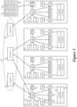
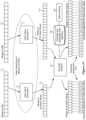
- FIG. 1illustrates a network control system 100 that uses the novel controller load distribution scheme of some embodiments of the invention. Specifically, it illustrates a cluster 101 of three controllers 102 - 106 that manage four physical forwarding elements 112 - 118 that execute on four computers 122 - 128 to forward data between these computers. Each computer executes two or more virtual machines (VMs) 132 - 138 , one agent 150 , an index generator 152 , and a proxy 154 for each VM. Each computer also has a storage 156 for storing a controller assignment list.
- VMsvirtual machines
- the managed physical forwarding elements 112 - 118are software forwarding elements that execute on host computers 122 - 128 . In other embodiments, however, one or more of these physical forwarding elements may be standalone hardware forwarding elements. Also, even though FIG. 1 illustrates one PFE executing on each host, some embodiments have more than one PFE of more than one PFE type executing on a host. For instance, each host in some embodiments executes an L2 switch and an L3 router, as further described below.
- the software forwarding elementsare referred to as physical forwarding elements, in order to distinguish them from logical forwarding elements, which are logical constructs that are not tied to the physical world.
- the software switching elementsare referred to as PFEs because they exist and operate in the physical world, whereas logical forwarding elements are simply a logical representation of a forwarding element that is presented to a user. Examples of logical forwarding elements include logical switches, logical routers, etc.
- the controller cluster 101manages the physical forwarding elements 112 - 118 to implement different logical forwarding elements (LFEs) for different virtual networks of different tenants, users, departments, etc. that use the same shared compute and networking resources.
- LFEslogical forwarding elements
- the physical forwarding elements 112 - 118can perform L2 switch functionality and specify two different logical L2 switches 202 and 204 , with each logical L2 switch connecting the VMs of a different entity.
- the logical L2 switch 202connects four VMs 132 , 135 , 137 and 138 of one entity (e.g., one tenant) that execute on four different host computers 122 - 128
- logical L2 switch 204connects four VMs 133 , 134 , 136 and 139 of another entity (e.g., another tenant) that execute on the same four host computers 122 - 128
- the operation of each logical switchis distributed across the PFEs 112 - 118 .
- a logical switchprovides an L2 connectivity to VMs connected to the logical switch.
- the logical L2 connectivitymay be VXLAN backed (and can also be implemented with any other overlay technologies like NVGRE, STT, etc.).
- VNIVXLAN Network Identifier
- the controllersexecute network control applications that direct the management of these elements.
- the majority of the LFE operationsare performed by the PFEs according to the configuration of these PFEs that is specified by the controller cluster 101 .
- some of the LFE operationsrequire real-time input from the controller clusters. Examples of such operations that require real-time input in some embodiments include ARP broadcasts, DHCP broadcasts, etc. These examples are described in concurrently filed U.S. patent application Ser. No. 14/070,360, entitled “Proxy Methods for Suppressing Broadcast Traffic in a Network,” now issued as U.S. Pat. No. 9,548,965.
- each hosthas (1) a proxy 154 in the datapath between the VM and the PFE, and (2) an agent 150 .
- the proxies 154are used to capture certain requests (e.g., ARP requests) from the VMs and re-route these requests to the agents, so that the agents can communicate with the controllers and obtain data needed to process such requests.
- the proxiesare part of virtual network interface cards (VNICs) of the VMs or are part of PFEs (e.g., the virtual ports of the PFEs).
- VNICsvirtual network interface cards
- PFEse.g., the virtual ports of the PFEs.
- the proxiescan be viewed as function calls to the agents.
- each agent 150maintains one or more control channel communication sessions (e.g., TCP/IP sessions) with one or more controllers, in order to process such requests.
- FIG. 1shows control channel connections (1) between controller 102 and agent 150 of computer 122 , (2) between controller 104 and agents 150 of computers 122 , 124 and 126 , and (3) between controller 106 and agent 150 of computer 128 .
- each agentestablishes out-of-band control channel communication connection (e.g., a TCP/IP connection) with each controller that is responsible for each LFE that is implemented or may be implemented with the agent's associated PFE.
- out-of-band control channel communication connectione.g., a TCP/IP connection
- an agentcan establish multiple different connections with the same controller for multiple different LFEs handled by the agent, while in other embodiments, an agent establishes only on connection with a controller for all LFEs handled by the agent.
- the controller cluster 101 of some embodimentsdistributes a controller assignment list 160 to the host computers.
- the host computersuse this list to identify the controllers with which they need to interact to perform some of the forwarding operations of the LFEs that their PFEs implement.
- the agents 150(1) review the controller assignment list to identify the appropriate controllers for the different LFEs, and (2) establish control channel communications with these controllers to obtain the data needed for effectuating the forwarding operations of their associated LFEs.
- the controller assignment listincludes two parameters for each LFE.
- One parameteris an index value 162 (called an index parameter) that is derivable from an identifier that identifies the LFE (called LFE identifiers).
- the other parameteris a controller identifier 164 (called a controller identifier) that identifies a controller that is responsible for processing requests for the LFE.
- the controller identifieris an address (e.g., IP address) of the controller, while in other embodiments, the controller identifier is a value from which the address of the controller can be obtained (e.g., through another table).
- the controllers and the hostsuse the same index generation process to generate the index values for different LFEs of the same type.
- the controllers and the hostsuse the same index generation process for different types of LFEs, while in other embodiments they use different index generation process for different types of LFEs.
- one controlleri.e., a master controller
- the controller set(e.g., the master controller) does not explicitly generate the index values from the LFE identifiers (the LFEIs), but rather assigns a defined range of index values (associated with a range of LFEIs) to the different controllers, as further described below.
- An agent of a hostcan identify the controller for a particular LFE implemented by the host's PFE by (1) using the index generator 132 for the correct LFE type to generate an index value and (2) using the generated index value to retrieve the controller identifier from the controller assignment list 160 that is stored in the storage 156 .
- the retrieved controller identifierspecifies the controller for the agent to connect to in order to obtain necessary data for processing requests associated with the particular LFE's operations.
- the controller identifierin some embodiments specifies the address of the controller, while in other embodiments this identifier is used to retrieve the address of the controller (e.g., through another table).
- the agentidentifies a controller for an LFE when it sets up the LFE on the host, or upon receiving a new controller assignment list from the controller.
- the agentestablishes a connection (e.g., a TCP/IP session) with the LFE's controller upon identifying the controller, so that it can later use this connection to process subsequent LFE operations that need the controller's input.
- the index generation process of some embodimentsis a hash operation that maps identifiers for different types of LFEs to the same range of index values. For instance, in some embodiments, the hash operation ends with a modulo operation that expresses the final hashed index value in terms of an integer that is the remainder value of the operation.
- the controller sete.g., the master controller
- the assignment of the controllers to different ranges of hash valuesis done in a manner to achieve a desired load balancing across the controllers.
- this assignmentis uniform or approximately uniform in terms of the number of controllers and the number of LFEs.
- the controller clustere.g., the master controller assigns equal sized hash value ranges to different controllers as its distribution scheme distributes the LFE identifiers uniformly across the LFEI range in order to ensure even distribution across the hash value ranges.
- this assignmentis uniform or approximately uniform in terms of data that is collected dynamically, such as data traffic load for each LFE, the number of VMs for each LFE, etc.
- using a hash/modulo processallows the distribution scheme of some embodiments to assign a defined range of index values to the different controllers without requiring the controller set (e.g., the master controller) to explicitly compute an index value for each LFE. Only the host agents need to use the hashing process to generate an index value that identifies a controller in the controller assignment list.
- the same hash/modulo processis used for different LFE types, as mentioned above.
- different hash/modulo processesare used for different LFE types (e.g., in order to allow different LFE types to different hash value ranges).
- Section ISection II
- Section IIthe operation of the controller cluster of some embodiments will further be described.
- Section IIIdescribes an electronic system with which some embodiments are implemented.
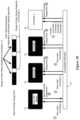
- FIG. 3illustrates a network control system 300 of some embodiments of the invention.
- This control system 300is similar to the control system 100 of FIG. 1 with a few differences. Like the system 100 , it includes a controller cluster 101 with three controllers 102 - 106 that manage physical forwarding elements that execute on four computers to forward data between these computers. Also, like the computers of the control system 100 , the computers 322 - 328 of the system 300 execute two or more virtual machines (VMs) 132 - 138 , one agent 350 , and a proxy 154 for each VM. Each computer 322 - 328 also has a storage 156 for storing a controller assignment list.
- VMsvirtual machines
- the computers 322 - 328 in the control system 300each have two types of physical forwarding elements 372 and 374 , two index generators 351 and 353 , and a connection list 375 .
- the two PFE types on each computerare an L2 switch 372 and an L3 router 374 . Both these elements are software forwarding elements that execute on host computers 322 - 328 .
- each logical switchmay be connecting different groups of VMs of a tenant and each logical switch connects to the other logical switch through the logical router so that all of the VMs of the tenant can be connected through the logical network formed by the logical switches and the logical routers.
- FIG. 5illustrates another example of the distributed network topology that can be created with the logical switches and routers that are implemented by the L2 switches 372 and L3 routers 374 of the computers 322 - 328 .
- each logical switch (LS) 502 or 504still provides L2 connectivity between several VMs.
- Each logical router 505 or 510serves as an L3 interface between its distributed network's LS 502 or 504 and computing devices outside of its distributed network.
- the same functionalitycan also be provided in some embodiments by the logical router 405 of FIG. 4 .
- the agents 350 and proxies 154 of the control system 300are used to obtain data in real-time from the controller cluster 101 in order to facilitate the performance of some of the LFE operations (i.e., LS operations or LR operations).
- the agents 350 of the system 300(1) review the controller assignment list 160 that the controller cluster 100 distributes to identify the appropriate controllers for the various different LFEs, and (2) establish control communication channels with these controllers so that they can later use communication channels to obtain the needed data for effectuating subsequent forwarding operations of their associated LFEs.
- the agents 350 of the system 300use two different index generators 351 and 353 to generate index values for two different types of logical forwarding elements that their hosts execute. Specifically, the agents use the index generator 351 to generate index values for the different logical switches that their associated L2 switches 372 implement, while using index generator 353 to generate index values for the different logical routers that their associated L3 routers 374 implement.
- the index generator 351generates its index values from the logical switch (LS) identifiers that identify the different LS's, while the index generator 353 generates its index values from the logical router (LR) identifiers that identify the different LRs.
- LSlogical switch
- LRlogical router
- the LS or LR identifieris an identifier that uniquely specifies a logical switch or logical router in a locality (e.g., a data center or a group of hosts in a data center), while in other embodiments the identifier is an identifier that represents an LFE that spans multiple localities (e.g., spans two data centers).
- the LS identifierin some embodiments is the VNI of a logical switch. While FIG. 3 and some of the subsequent figures show two index generators for generating index values from the LS identifiers and the LR identifiers, the agents of some embodiments use one index generator for both LS and LR identifiers.
- the agentuses the index generator and the controller assignment list when it is setting up a LS or LR on its host, or when it receives a new controller assignment list to process from the controller.
- an agent(1) uses the generated index value to retrieve the controller identifier from the controller assignment list 160 , (2) establishes a connection (e.g., a TCP/IP session) with the identified controller, and (3) stores the identity of this controller and/or this established connection in the connection list 375 .
- the agentsubsequently uses the connection list 375 to identify the controller or connection to use to process subsequent operations of the particular LS or LR.
- An agent 350performs the process 600 in some embodiments each time its host boots up, and the agent needs to establish its control channel communication sessions with the controllers.
- the process 600will be described below by reference to FIGS. 7 - 10 , which illustrate examples of sub-operations of this process.
- the process 600initially subscribes (at 605 ) to a controller to receive a controller assignment list and to receive subsequent updates to this list.
- the agentis configured to contact one controller to request such a subscription. In other embodiments, however, the agent is configured to randomly pick one controller for a pool of potential controllers as the controller to contact to receive the controller assignment list and updates to this list.
- the process 600receives (at 610 ) a controller assignment list from the controller to which it subscribed. The process stores (at 610 ) this list locally on the host.
- FIG. 7illustrates an example of the agent 350 subscribing to the controller 104 , receiving a controller assignment list from this controller, and storing the controller assignment list in the storage 156 .
- the processselects a logical forwarding element (LFE) that a physical forwarding element of its host has to implement or should be prepared to possibly implement.
- LFElogical forwarding element
- a host's PFEis not implementing an LFE, it is set up for the LFE so that it can be ready to seamlessly join the implementation of the LFE when a VM that uses the LFE is instantiated on the host.
- a hostis prepared to implement an LFE when the host is part of a computational cluster of hosts and one of the other hosts in the cluster is currently implementing the LFE.
- LFEsinclude LS's and LRs. Accordingly, at 615 , the process may select any LS or LR that it has to implement or should be prepared to implement. Next, at 620 , the process uses the selected LFE's identifier to generate an index value. To do this, the process uses the index generator 351 or 353 that is appropriate for the LFE's type (e.g., uses the L2 index generator if the selected LFE is a LS, and uses the L3 index generator when the selected LFE is a LR). As mentioned above, some embodiments use one index generator for different types of LFEs.
- the processuses the generated index value to retrieve the identity of the controller for the selected LFE (i.e., the LFE selected at 615 ) from the controller assignment list. In other words, at 625 , the process identifies the record in the list that has an index value that matches the generated index value, and retrieves the controller identifier of this identified record.
- the processdetermines whether it previously created a connection to the identified controller (i.e., the controller identified at 625 ) for another LFE. This determination is made because the process 600 of some embodiments only makes one control channel connection between each host agent and a controller, and uses this connection to obtain from the controller data for all LFEs handled by the controller. In other embodiments, however, the process establishes multiple control channel connections between an agent and a controller, because the process in these embodiments establishes a unique control channel connection between the agent and the controller for each LFE handled by the controller.
- the processdetermines (at 630 ) that it previously created a connection to the identified controller, it adds (at 635 ) a new record in the connection list to specify this connection and/or the identified controller for the LFE selected at 615 .
- the creation of records in the connection listis further described below by reference to operation 645 .
- the process of some embodimentsuses the previously specified connection to send to the controller dynamic data pertaining to the selected LFE. Examples of such data include ARP table for an L2 logical switch and a routing table for an L3 logical router. The controller uses this data to subsequently process data requests from the agent. From 635 , the process transitions to 650 , which will be further described below.
- the processdetermines (at 630 ) that it did not previously create a connection to the identified controller, it establishes (at 640 ) a connection with the controller identified at 625 .
- the connectionis a TCP/IP connection.
- the agentwill subsequently use this connection to communicate with the controller to process certain operations of the LFE.
- the controllermight reject a request from the process 600 to establish a connection to handle data requests for a particular LFE. For instance, in some cases, the controller might not have received the controller assignment list that specifies that the controller is responsible for the particular LFE.
- the process 600sets a timer (at 630 ) when its connection request is rejected, so that it can re-submit the request again once the timer expires, by which time the controller should have received the new controller assignment list.
- the processre-sets the timer multiple times when the controller rejects a connection request multiple times, in order to give the controller sufficient time to receive a new controller assignment list. The setting and use of this timer will be further described below by reference to FIG. 21 .
- the processalso sends dynamic data to the controller once the controller accepts the connection.
- This dynamic dataincludes data pertaining to the selected LFE. Examples of such data include an ARP table for an L2 logical switch and a routing table for an L3 logical router.
- the controlleruses this data to subsequently process data requests from the agent (e.g., process ARP requests from the host agents, or distribute routing table to the hosts).
- the processstores (at 645 ) the identity of the new controller and/or identity of the newly established connection in the connection list 375 for the LFE. Specifically, in some embodiments, a record is created in the connection list that specifies the LFE, the identifier for its associated controller, and the identifier for the connection session. In some embodiments, the connection session is not stored in this connection list. As mentioned above, and further described below, the agent uses the connection list to process subsequent LFE operations that need controller input.
- the processdetermines whether it has examined all the LFEs that its host has to implement or be prepared to implement. If so, it transition to 655 , which will be further described below. Otherwise, the process transitions to 615 to select another LFE and repeat its operations 620 - 650 for this LFE.
- FIG. 8illustrates an example of the agent 350 using the index generators to generate index values for its associated LFEs, identifying corresponding controllers in the controller assignment list based on the generated index values, establishing connections with the identified controllers, and storing the identities of the controllers and/or connections for the LFEs in the connection lists.
- one connectionis established between the agent 350 and the controller 102 for the LS 20
- another connectionis established between this agent and the controller 106 for the LR 73 .
- LS 20 and LR 73are two LFEs of several LFEs (including LS 27 , LS 35 , LR 101 , LR 110 , etc.) that the L2 switch and L3 router of the host implement.
- the connections for these other LFEs (LS 27 , LS 35 , LR 101 , LR 110 , etc.), and the creation of these connections,are not shown in order not to obscure the description with unnecessary detail.
- each six operation setincludes (1) directing (1 or 7) the appropriate index generator to generate an index value from the LS identifier or the LR identifier, (2) obtaining (2 or 8) the generated index value from the index generator, (3) examining (3 or 9) the controller assignment list for the controller identifier associated with the generated index value, (4) retrieving (4 or 10) the controller identifier based on the index value, (5) establishing (5 or 11) a connection with the identified controller, and (6) storing (6 or 12) the identity of the controller and/or the connection in the connection list along with the associated identifier of the LS or LR.
- the connection listincludes a record for the connection with controller 1 for LS 20 , and a record for the connection with controller 3 for the LR 73 .
- Each of these recordsincludes the IP address of its corresponding controller and the session identifier (e.g., TCP/IP session) of its corresponding connection.
- the session identifiere.g., TCP/IP session
- the controller IP addressinstead of the controller IP address, other embodiments use other attributes of a controller such as the controller's identifier in the connection list. Also, other embodiments do not store the session identifier for the connection.
- the processdetermines (at 650 ) that it has examined all the LFEs that its host has to implement or be prepared to implement, it uses (at 655 ) the controller connections specified in the connection list to process subsequent LFE operations that need controller input, until the agent receives an update to the controller assignment list.
- the operation of the agent when it receives an updated controller assignment listwill be further described below by reference to FIG. 11 .
- FIGS. 9 and 10illustrate two examples that further explain the operation 645 of the process 600 .
- FIG. 9illustrates the case where the agent 350 uses the connection list to contact the correct controller to process a data request for LS 20
- FIG. 10illustrates the case where the agent 350 uses the connection list to contact the correct controller to process a data request for LR 73 .
- the agent:
- An example of such an LS requestis an ARP (address resolution protocol) request.
- a VMsends an ARP request when it needs to identify the MAC (media access control) address for another VM or device for which it has an IP address.
- ARP requestsare broadcast requests that consume a lot of resources in hosted, virtualized environments, especially as the number of hosts and/or VMs increases. Accordingly, some have suggested a proxy based scheme for suppressing ARP broadcast messages, as described in concurrently filed U.S. patent application Ser. No. 14/070,360, entitled “Proxy Methods for Suppressing Broadcast Traffic in a Network,” now issued as U.S. Pat. No. 9,548,965. In this scheme, a proxy (like proxy 152 of FIG.
- a LR requestis a DHCP (dynamic host configuration protocol) request.
- a VMsends a DHCP discover broadcast when it needs to identify a DHCP server to provide it with DHCP configuration data.
- DHCP requestsare broadcast requests that consume a lot of resources in hosted, virtualized environments, especially as the number of hosts increases. Accordingly, some have suggested a proxy based scheme for suppressing DHCP broadcast messages, as described in U.S. patent application Ser. No. 14/070,360, entitled “Proxy Methods for Suppressing Broadcast Traffic in a Network,” now issued as U.S. Pat. No. 9,548,965. In this scheme, a proxy (like proxy 152 of FIG.
- FIG. 10is used to intercept a DHCP request and re-route it to an agent (like agent 350 of FIG. 10 ), which then routes this request to the appropriate controller to receive the appropriate DHCP messages and configuration.
- agentlike agent 350 of FIG. 10
- FIG. 10 and the process 600 illustrated in FIG. 6can be used to identify the correct controller to contact to handle DCHP discover broadcast messages for a particular LR.
- An edge virtual routeris a virtual router that handles north or south traffic out of or and into the virtual L3 network.
- the non-edge virtual routersare virtual routers that handle east-west traffic within the virtual L3 network.
- the edge routerspublish their routing tables to the non-edge virtual routers.
- each edge virtual router of a virtual L3 networkuses the controller identification process of some embodiments to identify the correct controller to send its routing tables, so that this controller can push these tables to the non-edge virtual routers in the same virtual L3 network or can serve as a node from which these non-edge virtual routes can pull these tables.
- FIG. 11illustrates a process 1100 that the agent performs when it receives and stores an updated controller assignment list, in order to update its connection list to reflect the changes in the updated controller assignment list.
- the process 1100is an asynchronous process because the agent performs this process whenever it asynchronously receives an updated controller assignment list from the controller cluster (e.g., from the controller to which the agent subscribed).
- This processis very similar to the process 600 of FIG. 6 , in that it includes operations 615 - 625 , 630 - 645 , and 650 - 655 . The only difference is that it does not include operation 605 and 610 , while including operations 1105 and 1110 .
- the storage operation 610is not shown in FIG. 11 , as the description of the process 1100 starts after the agent receives and stores an updated controller assignment list.
- the process 1100performs the operation 1105 to identify new controller assignments for the LFEs. Specifically, after identifying a controller (in the controller assignment list) for a selected LFE, the process 1100 determines (at 1105 ) whether it previously specified the identified controller as the controller for the selected LFE in the connection list 375 . If so, it skips operations 640 , 645 , and 1110 , and transitions to 650 .
- the process 1100transitions to 640 to perform the above-described operations 640 and 645 to establish a connection with the newly specified controller identified at 625 and store the identity of this controller and/or this connection in the connection list for the selected LFE.
- the process 1100closes (at 1110 ) the connection to the controller that was previously specified for the selected LFE, if this connection is not being used by the host's agent for any other LFE. Also, at 1110 , the process removes this previous connection from the connection list for the LFE. In some embodiments, the process 1100 performs the operations at 1110 before it records (at 645 ) the new connection to the new controller.
- each time that each controller sends its subscribed hosts updated controller listsit might not include the entire list, but only include the records in this list that have been updated. This might be the case because in some embodiments, the master controller does not distribute the controller assignment list in its entirety each time that it updates this list. Rather, each time that it updates a portion of the master controller list, the master controller of some embodiments also distributes only the portion of the controller assignment list that it has updated.
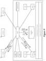
- FIG. 12illustrates an example of how the controller cluster of some embodiments generates a controller assignment list. Specifically, it illustrates three controllers 102 , 104 and 106 that operate on top of a distributed coordination management layer 1205 .
- the coordination management layerallows the controllers to coordinate one or more of their activities. One of their activities is the election of a master controller, so that this controller can then generate the controller assignment list and distribute this list to the other controllers.
- the coordination management layerhas a coordination manager instance executing on each controller.
- the different instances of the coordination manager on the different controllerscommunicate in order to achieve several objectives. These objectives in some embodiments include: (1) keeping status of all controller nodes, such as their IP address, their UUID (universally unique identifier), and when they join/leave the cluster, (2) synchronizing data between controller nodes, and (3) selecting a master for the control-cluster, and reselecting the master when the previous master controller leaves the cluster.
- One example of a distributed coordination management layer that can be used to perform this functionalityis the Zookeeper program. Additional examples of the coordination management layer are described in U.S. Published Patent Application 2013/0058356.
- the first operationis the coordination management layer's notification to each controller of the identity of the other controllers in the controller cluster.
- This operationalso entails notifying the controller that has been elected as the master controller that it is the master controller. For instance, in the example illustrated in FIG. 12 , the controller 102 is notified that it is the master controller, and each controller is notified that the cluster contains the three controllers 102 , 104 , and 106 .
- the second operationis the master controller 102 generating the controller assignment list, and sending this list to the other controllers.
- the third operationis the non-master controllers receiving the controller assignment list.
- the controller assignment listin some embodiments segments the possible index values into several different ranges, and assigns these ranges to three different controllers 102 , 104 and 106 .
- the index valuesare to be used to match to index values that the host agents generate from the identifiers of the LFE. By matching the index values, the agents can identify the records in the controller assignment list that specify the controllers for the LFEs.
- the master controllermay generate the controller list differently. For instance, some embodiments have the agents use a hash/modulo operation that maps all possible LFE identifiers to a common range of index values. For some of these embodiments, the master controller does not explicitly generate the index values for the different possible LFE identifiers. Rather, it simply segments the possible index values into several different ranges, and assigns the different ranges to the different controllers.
- FIGS. 13 and 14illustrate how the master controller of some embodiments generates the controller assignment list without explicitly generating the index values for the different possible LFE identifiers.
- FIG. 13illustrates a process 1300 performed by the master controller
- FIG. 14presents a pictorial illustration of the segmentation of an index value range on the controller side and the generation of index values on the host side.
- FIG. 13illustrates that the process 1300 initially receives (at 1305 ) a notification that its controller is the master controller.
- the processspecifies the controller assignment list by dividing the possible index value range into several index value segments, with each segment being assigned to one controller.
- the processdistributes the controller assignment list to other controllers, and stores a local copy of this assignment list for the master controller.
- FIG. 14illustrates one example of generating a controller assignment list without explicitly generating the index values on the controller side.
- the host agentsuse hash/modulo index value generators that end a hash operation with a modulo operation that expresses the final hashed index value in terms of an integer that is the remainder value of the modulo operation. Because of this, the master controller simply selects the range of potential remainder values as the range of possible index values, and uniformly divides this range among the different controllers based on an assumption that the range of LFE identifiers will be uniformly spread so as to produce a uniform distribution across the range of possible index values.
- the range 1415is the range of potential remainder values for the hash/modulo operation, and hence is selected by the master controller as the range of possible index values. As shown in this figure, the master controller divides this range 1415 into three equal sized segments and assigns each segment to one of the three controllers 102 , 104 and 106 .
- FIG. 14also shows the hash/modulo index value generator or generators 1410 of the host agents mapping the LS identifiers and LR identifiers to the range of possible index values, and hence to the segments in this range.
- the index value generator 1410multiplies LS identifier (e.g., the VNI of a logical switch) or an LR identifier (e.g., the LRI of a logical router) with a large number, and then performs a modulo operation to obtain a remainder value that serves as the logical switch's or logical router's index value.
- the index value generatoruses a Knuth multiplicative hash to generate evenly distributed random index numbers.
- the host agentscan then use the generated index values to retrieve controller identifiers from the controller assignment list for the different LFEs. Based on the values of the LS and LR identifiers, some of the index values may go unused by the host agents. However, the use of the hash/modulo index value generator(s) by the host agents allows the controller cluster (e.g., the master controller) to forego explicitly computing an index value for each LFE.
- the controller clustere.g., the master controller
- the master controlleruses index value generators to generate index values for the different possible LFE identifiers.
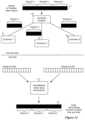
- FIGS. 15 and 16illustrate the operation of such a master controller.
- FIG. 15illustrates a process 1500 for generating index values and assigning these index values to different controllers
- FIG. 16presents a pictorial illustration of these operations.
- the process 1500initially selects (at 1505 ) one possible LFE identifier (LFEI). It then uses (at 1510 ) an index generator that is appropriate for the LFE of the selected LFEI to generate an index value based on the LFEI.
- FIG. 16illustrates an example of this operation. Specifically, it illustrates two different index value generators 1605 and 1610 of the master controller mapping two different ranges of identifiers, a LS identifier range 1630 and a LR identifier range 1635 , to one range of index values 1615 that is common for the range of the LS and LR identifiers.
- the process 1500associates ( 1515 ) a controller to the generated index value according to a distribution process that maximizes the even distribution of the generated index values among the controllers.
- the processdetermines whether it has iterated through all the LFE identifiers. If so, it ends. Otherwise, it returns to 1505 to select another LFEI and to repeat operations 1510 , 1515 , and 1520 .
- FIG. 16illustrates an example of the completed controller assignment list. Specifically, it illustrates a controller assignment list 1620 that includes the range of index values 1615 and number of controller identifiers 1625 that specify a controller identifier for each specified index value.
- the controller assignment list 1620is produced by a controller assignor 1630 that uniformly distributes the index values (produced by index value generators 1605 and 1610 for the LSIs and the LRIs) across the three controllers 102 , 104 , and 106 .
- the master controlleruses still other schemes for generating the index values.
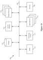
- FIG. 17illustrates a master controller of some embodiments using index generators 1705 and 1710 to map the different LS and LR identifier ranges 1715 and 1720 to different ranges of index values 1725 and 1730 .
- the controller assignor 1735 of the master controllerthen uses these two different index value ranges to specify a controller assignment list 1740 .
- this controller assignment listincludes one set of records 1745 that map the range of LS index values to the different controllers and another set of records 1750 that map the range of LR index values to these controllers.
- the above-described controller assignment processesassign controllers to ranges of index values and distribute loads across the controllers based on statically expressed parameters. For instance, some of the above-described processes distribute the index value range evenly amongst the controllers.
- static approachmight not accurately track the dynamic realities of the network control system. For instance, even when the number of LFE identifiers assigned to a first controller equal the number of LFE identifiers assigned to a second controller, the LFEs assigned to the first controller might impose more burden on the first controller, than the LFEs assigned to the second controller assign to this controller.
- the master controller of some embodimentsassigns the LFEs to the different controllers based on dynamically gathered data, such as the number of VMs assigned to each controller, the number of packets passing through the LFEs, the number of host-controller connections for each controller, or other dynamically collected data regarding the load on the LFEs and/or controllers.
- FIGS. 18 and 19illustrate two examples of how master controllers in two different embodiments generate controller assignment lists from dynamically collected data.
- FIG. 18illustrates an approach that is similar to the approach described above by reference to FIG. 16 , except that the index generators map LS and LR identifiers to a common index value range based on LFE and/or controller load data 1850 that a data collector 1855 of the master controller gathers.
- more LS and LR identifiersmay be assigned to a first index value or index value range than to second index value or index value range, because the index generators determine that fewer LS's and/or LRs should be assigned to a second controller associated with the second index value or index value range than to a first controller associated with the first index value or index value range.
- the index generatorsmake this determination in some embodiments after determining that the load on the second controller is more than the load on the first controller.
- an index generatorcomputes a traffic weight factor based on the number of hypervisors connected, stats of the traffic (ARP messages, route update messages, etc), the scale of configurations (e.g. how many L2 networks are included in the L3 component), etc.
- the index generatorthen generates the hash value as an exponential operation on the “weight” value. This results in the larger weight values being distributed more sparsely in the hash table, which increases the possibility of distributing them to different controller nodes.
- the actual weight valuefalls into a large range, and this makes unlikely that two identifiers have the same weight.
- FIG. 19an approach similar to the approach described above by reference to FIG. 17 , except that the controller assignor 1930 assigns the index values of the LFEs and LRs across the three controllers 102 , 104 , and 106 based on LFE and/or controller load data 1950 that the master controller's data collector 1955 gathers.
- this dynamic allocation of dataresults in more of the index values (i.e., more of the LFEs) being assigned to the first controller, and fewer of the index values (i.e., fewer of the LFEs) being assigned to the second controller, as shown in FIG. 19 .
- the fewer number of LFEs assigned to the second controllerplace approximately the same load on the second controller as the larger number of LFEs assigned to the first controller place on this controller.
- the host computersinclude index generators to generate index values for the LFEs that allow the agents to identify the correct record in the controller assignment lists that they receive.
- the host computersdo not have index generators, do not generate index values, and do not even receive controller assignment lists.
- each host's agentcontacts the master controller for each of its LFEs in order to identify the controller for the LFE. Once the agent is notified of the controller identity for an LFE, the agent creates a connection with this controller for its LFE, if such a connection was not previously specified, and adds this connection to its connection list, which it then uses to process subsequent requests.
- the controller assignordoes not need index values to be generated, as it maintains its controller assignment list in terms of the LFE identifiers. Specifically, the controller assignor uses the dynamically collected data 1950 to assign different LFEs, and to adjust dynamically the different LFEs, to the different controllers, and to express these assignments in terms of the LFEIs.
- index generators in the host computersis advantageous in that it does not require the controller assignment list to be distributed each time that it is modified based on dynamically collected data.
- the controller assignment listis not frequently updated based on the dynamically collected data
- having the hosts generate the index valuesis preferable as it does not add to the master controller the load associated with the building of each host's connection list.
- FIG. 20illustrates the operations of the network control system when a new controller is added to the controller cluster.
- the coordination management layer 1205notifies the currently operating controllers 102 , 104 , and 106 that a new controller 108 has been added to the controller cluster.
- the coordination management layeralso informs the new controller 108 of the identity of all the current controllers in the cluster.
- the master controller 102Upon noting the addition of the new controller, the master controller 102 generates a new controller assignment list, and distributes this new list to the other controllers 104 , 106 and 108 , as shown in FIG. 20 .
- the controller assignor of the master controllergenerates in some embodiments the new controller assignment list by trying to minimize the changes to any one controllers assignments. For instance, in some embodiments, the controller assignor incrementally modifies each controller's existing assignment so that no one controller's assignment is drastically modified.
- the master controllerin some embodiments takes the same fraction of the LFE assignments or index value range assignments (e.g., one over the number of the previous controllers plus the number of added controller(s)) from each previous controller's assigned range and adds this fraction to the assignment of the new controller(s).
- FIG. 20illustrates this incremental change by showing that one fourth of the previous assignments of each of the previous controllers 102 , 104 , and 106 has been assigned to the new controller 108 . This leaves each of the previous controllers with three fourths of the previous assignments.
- the master controlleralso runs a timer, which when expired causes the master controller to check periodically that the controller nodes are well balanced. Whenever it detects that the controllers are not well balanced, the master controller will generate and send a new controller assignment list.
- the hostsWhenever the master controller sends a controller assignment list update, the hosts will receive their updates from the controllers (including the master controller) to which they subscribed to receive such updates. Also, when such updates re-assign an LFE from one controller to another, the host agents that deal with this LFE have to close their connection to the previous controller and establish a new connection to the new controller, if such a connection is needed.
- FIG. 21illustrates an example of a host closing an old, invalid connection to an old controller and opening a new, valid connection to a new controller.
- this figureshows that after the master controller 102 has sent a new controller assignment list to the other controllers 104 and 106 , it sends the modified controller assignment list to a host that has subscribed to the master controller to receive such updates. After receiving the new controller list assignment, the host clears all the data from the old connection to the controller 104 for the LS 20 , closes its old connection to controller 104 for LS 20 , and establishes a new connection to controller 106 for LS 20 . While FIG. 21 illustrates the master controller 102 providing the new controller assignment list to the host, one of ordinary skill will realize that in some embodiments any other controller could provide this list to the host so long as that host subscribed to that controller to receive such updated lists.
- the new controller for an LFEmight receive and/or process its new controller assignment list after a host receives and processes this list for the LFE. If that is the case, the new controller and host will have inconsistent states. To handle this case, the controller is configured to reject a connection by a host agent for a particular LFE until the controller's assignment list specifies that it should accept connections for the particular LFE. In such situations, the host agent starts a timer and tries again to establish the connection with the new controller upon the expiration of the timer.
- the master controllermay not distribute the controller assignment list in its entirety each time that it updates this list. Rather, each time that it updates a portion of the master controller list, the master controller of some embodiments might only distribute the portion of the controller assignment list that it has updated. Similarly, in some embodiments, each time that each controller sends its subscribed hosts updated controller lists, it might not include the entire list, but only include the records in this list that have been updated.
- the master controllerWhen a controller fails, the master controller has to re-specify the controller assignment list. As in the case of the addition of a controller, the master controller of some embodiments re-specifies the controller assignment list in order to minimize the LFE assignments or index value assignments to each of the remaining controllers.
- FIGS. 22 and 23illustrate an example of this operation of the master.
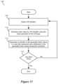
- FIG. 22illustrates the process 2200 that the master controller performs when a controller fails.
- the process 2200initially receives (at 2205 ) notification from the coordination management layer that one of the non-master controllers has failed.
- FIG. 23illustrates an example of one of the controllers (controller 106 ) of a four controller cluster failing. It also illustrates that before this failure, each controller 102 , 104 , 106 or 108 had a different range of index values assigned to it.
- This figurealso provides a second pictorial illustration of the index values I 1 -I 12 being assigned to the controllers 102 , 104 , 106 , and 108 .
- Each of these index valuescan represent an LFE, as it can be generated from an LFE identifier.
- the process 2200re-specifies (at 2210 ) the controller assignment list, distributes (at 2215 ) the newly specified controller assignment list to the other controllers, and then ends.
- the processre-specifies (at 2210 ) the controller assignment list in order to minimize index value assignments to each of the remaining controllers.
- the master's controller assignorincrementally modifies each controller's existing assignment so that no one controller's assignment is drastically increased or modified.
- the master controllerin some embodiments takes the same fraction of the LFE assignments or index value range assignments (e.g., one over the number of the remaining controllers) from the failed controller's previous assignments and adds this fraction to the assignment of the remaining controllers.
- FIG. 23illustrates this incremental change by showing that each of the remaining controllers 102 , 104 and 108 is assigned one third of the previous assignments of the failed controller 106 .
- the failed controller 106was assigned index values 17 , 18 and 19 .
- the index 17is assigned to controller 104
- the index 19is assigned to controller 108
- the index 18is assigned to controller 102 .
- Computer readable storage mediumalso referred to as computer readable medium.
- processing unit(s)e.g., one or more processors, cores of processors, or other processing units
- processing unit(s)e.g., one or more processors, cores of processors, or other processing units
- Examples of computer readable mediainclude, but are not limited to, CD-ROMs, flash drives, RAM chips, hard drives, EPROMs, etc.
- the computer readable mediadoes not include carrier waves and electronic signals passing wirelessly or over wired connections.
- the term “software”is meant to include firmware residing in read-only memory or applications stored in magnetic storage, which can be read into memory for processing by a processor.
- multiple software inventionscan be implemented as sub-parts of a larger program while remaining distinct software inventions.
- multiple software inventionscan also be implemented as separate programs.
- any combination of separate programs that together implement a software invention described hereis within the scope of the invention.
- the software programswhen installed to operate on one or more electronic systems, define one or more specific machine implementations that execute and perform the operations of the software programs.
- FIG. 24conceptually illustrates an electronic system 2400 with which some embodiments of the invention are implemented.
- the electronic system 2400can be used to execute any of the control, virtualization, or operating system applications described above.
- the electronic system 2400may be a computer (e.g., a desktop computer, personal computer, tablet computer, server computer, mainframe, a blade computer etc.), phone, PDA, or any other sort of electronic device.
- Such an electronic systemincludes various types of computer readable media and interfaces for various other types of computer readable media.
- Electronic system 2400includes a bus 2405 , processing unit(s) 2410 , a system memory 2425 , a read-only memory 2430 , a permanent storage device 2435 , input devices 2440 , and output devices 2445 .
- the bus 2405collectively represents all system, peripheral, and chipset buses that communicatively connect the numerous internal devices of the electronic system 2400 .
- the bus 2405communicatively connects the processing unit(s) 2410 with the read-only memory 2430 , the system memory 2425 , and the permanent storage device 2435 .
- the processing unit(s) 2410retrieve instructions to execute and data to process in order to execute the processes of the invention.
- the processing unit(s)may be a single processor or a multi-core processor in different embodiments.
- the read-only-memory (ROM) 2430stores static data and instructions that are needed by the processing unit(s) 2410 and other modules of the electronic system.
- the permanent storage device 2435is a read-and-write memory device. This device is a non-volatile memory unit that stores instructions and data even when the electronic system 2400 is off. Some embodiments of the invention use a mass-storage device (such as a magnetic or optical disk and its corresponding disk drive) as the permanent storage device 2435 .
- the system memory 2425is a read-and-write memory device. However, unlike storage device 2435 , the system memory is a volatile read-and-write memory, such a random access memory.
- the system memorystores some of the instructions and data that the processor needs at runtime.
- the invention's processesare stored in the system memory 2425 , the permanent storage device 2435 , and/or the read-only memory 2430 . From these various memory units, the processing unit(s) 2410 retrieve instructions to execute and data to process in order to execute the processes of some embodiments.
- the bus 2405also connects to the input and output devices 2440 and 2445 .
- the input devicesenable the user to communicate information and select commands to the electronic system.
- the input devices 2440include alphanumeric keyboards and pointing devices (also called “cursor control devices”).
- the output devices 2445display images generated by the electronic system.
- the output devicesinclude printers and display devices, such as cathode ray tubes (CRT) or liquid crystal displays (LCD). Some embodiments include devices such as a touchscreen that function as both input and output devices.
- bus 2405also couples electronic system 2400 to a network 2465 through a network adapter (not shown).
- the computercan be a part of a network of computers (such as a local area network (“LAN”), a wide area network (“WAN”), or an Intranet, or a network of networks, such as the Internet. Any or all components of electronic system 2400 may be used in conjunction with the invention.
- Some embodimentsinclude electronic components, such as microprocessors, storage and memory that store computer program instructions in a machine-readable or computer-readable medium (alternatively referred to as computer-readable storage media, machine-readable media, or machine-readable storage media).
- computer-readable mediainclude RAM, ROM, read-only compact discs (CD-ROM), recordable compact discs (CD-R), rewritable compact discs (CD-RW), read-only digital versatile discs (e.g., DVD-ROM, dual-layer DVD-ROM), a variety of recordable/rewritable DVDs (e.g., DVD-RAM, DVD-RW, DVD+RW, etc.), flash memory (e.g., SD cards, mini-SD cards, micro-SD cards, etc.), magnetic and/or solid state hard drives, read-only and recordable Blu-Ray® discs, ultra density optical discs, any other optical or magnetic media, and floppy disks.
- CD-ROMcompact discs
- CD-Rrecordable compact discs
- the computer-readable mediamay store a computer program that is executable by at least one processing unit and includes sets of instructions for performing various operations.
- Examples of computer programs or computer codeinclude machine code, such as is produced by a compiler, and files including higher-level code that are executed by a computer, an electronic component, or a microprocessor using an interpreter.
- ASICsapplication specific integrated circuits
- FPGAsfield programmable gate arrays
- integrated circuitsexecute instructions that are stored on the circuit itself.
- the terms “computer”, “server”, “processor”, and “memory”all refer to electronic or other technological devices. These terms exclude people or groups of people.
- display or displayingmeans displaying on an electronic device.
- the terms “computer readable medium,” “computer readable media,” and “machine readable medium”are entirely restricted to tangible, physical objects that store information in a form that is readable by a computer. These terms exclude any wireless signals, wired download signals, and any other ephemeral or transitory signals.
- FIGS. 6 , 11 , 13 , 15 , and 22conceptually illustrate processes.
- the specific operations of these processesmay not be performed in the exact order shown and described.
- the specific operationsmay not be performed in one continuous series of operations, and different specific operations may be performed in different embodiments.
- the processcould be implemented using several sub-processes, or as part of a larger macro process.
Landscapes
- Engineering & Computer Science (AREA)
- Computer Networks & Wireless Communication (AREA)
- Signal Processing (AREA)
- Software Systems (AREA)
- Theoretical Computer Science (AREA)
- Human Computer Interaction (AREA)
- Physics & Mathematics (AREA)
- General Engineering & Computer Science (AREA)
- General Physics & Mathematics (AREA)
- Data Exchanges In Wide-Area Networks (AREA)
Abstract
Description
Claims (20)
Priority Applications (1)
| Application Number | Priority Date | Filing Date | Title |
|---|---|---|---|
| US16/179,971US11677611B2 (en) | 2013-10-10 | 2018-11-04 | Host side method of using a controller assignment list |
Applications Claiming Priority (4)
| Application Number | Priority Date | Filing Date | Title |
|---|---|---|---|
| US201361889519P | 2013-10-10 | 2013-10-10 | |
| US201361890321P | 2013-10-13 | 2013-10-13 | |
| US14/070,451US10148484B2 (en) | 2013-10-10 | 2013-11-01 | Host side method of using a controller assignment list |
| US16/179,971US11677611B2 (en) | 2013-10-10 | 2018-11-04 | Host side method of using a controller assignment list |
Related Parent Applications (1)
| Application Number | Title | Priority Date | Filing Date |
|---|---|---|---|
| US14/070,451ContinuationUS10148484B2 (en) | 2013-10-10 | 2013-11-01 | Host side method of using a controller assignment list |
Publications (2)
| Publication Number | Publication Date |
|---|---|
| US20190075012A1 US20190075012A1 (en) | 2019-03-07 |
| US11677611B2true US11677611B2 (en) | 2023-06-13 |
Family
ID=52809548
Family Applications (3)
| Application Number | Title | Priority Date | Filing Date |
|---|---|---|---|
| US14/070,451Active2036-01-29US10148484B2 (en) | 2013-10-10 | 2013-11-01 | Host side method of using a controller assignment list |
| US14/070,448Active2034-09-19US9596126B2 (en) | 2013-10-10 | 2013-11-01 | Controller side method of generating and updating a controller assignment list |
| US16/179,971Active2035-01-11US11677611B2 (en) | 2013-10-10 | 2018-11-04 | Host side method of using a controller assignment list |
Family Applications Before (2)
| Application Number | Title | Priority Date | Filing Date |
|---|---|---|---|
| US14/070,451Active2036-01-29US10148484B2 (en) | 2013-10-10 | 2013-11-01 | Host side method of using a controller assignment list |
| US14/070,448Active2034-09-19US9596126B2 (en) | 2013-10-10 | 2013-11-01 | Controller side method of generating and updating a controller assignment list |
Country Status (1)
| Country | Link |
|---|---|
| US (3) | US10148484B2 (en) |
Families Citing this family (43)
| Publication number | Priority date | Publication date | Assignee | Title |
|---|---|---|---|---|
| US9225638B2 (en) | 2013-05-09 | 2015-12-29 | Vmware, Inc. | Method and system for service switching using service tags |
| US9531676B2 (en)* | 2013-08-26 | 2016-12-27 | Nicira, Inc. | Proxy methods for suppressing broadcast traffic in a network |
| US10148484B2 (en) | 2013-10-10 | 2018-12-04 | Nicira, Inc. | Host side method of using a controller assignment list |
| US9977685B2 (en) | 2013-10-13 | 2018-05-22 | Nicira, Inc. | Configuration of logical router |
| US9893988B2 (en)* | 2014-03-27 | 2018-02-13 | Nicira, Inc. | Address resolution using multiple designated instances of a logical router |
| US10511458B2 (en) | 2014-09-30 | 2019-12-17 | Nicira, Inc. | Virtual distributed bridging |
| US9768980B2 (en) | 2014-09-30 | 2017-09-19 | Nicira, Inc. | Virtual distributed bridging |
| US9755898B2 (en) | 2014-09-30 | 2017-09-05 | Nicira, Inc. | Elastically managing a service node group |
| US10250443B2 (en) | 2014-09-30 | 2019-04-02 | Nicira, Inc. | Using physical location to modify behavior of a distributed virtual network element |
| US10516568B2 (en) | 2014-09-30 | 2019-12-24 | Nicira, Inc. | Controller driven reconfiguration of a multi-layered application or service model |
| US9774537B2 (en) | 2014-09-30 | 2017-09-26 | Nicira, Inc. | Dynamically adjusting load balancing |
| US10020960B2 (en) | 2014-09-30 | 2018-07-10 | Nicira, Inc. | Virtual distributed bridging |
| US9742726B2 (en)* | 2015-02-26 | 2017-08-22 | Red Hat Israel, Ltd. | Distributed dynamic host configuration protocol |
| US10594743B2 (en) | 2015-04-03 | 2020-03-17 | Nicira, Inc. | Method, apparatus, and system for implementing a content switch |
| US10361952B2 (en) | 2015-06-30 | 2019-07-23 | Nicira, Inc. | Intermediate logical interfaces in a virtual distributed router environment |
| US10225149B2 (en) | 2015-12-15 | 2019-03-05 | Nicira, Inc. | Method and tool for diagnosing logical networks |
| US10243797B2 (en) | 2016-03-14 | 2019-03-26 | Nicira, Inc. | Identifying the realization status of logical entities based on a global realization number |
| US10241820B2 (en) | 2016-03-14 | 2019-03-26 | Nicira, Inc. | Determining the realization status of logical entities in logical networks |
| US10805181B2 (en) | 2017-10-29 | 2020-10-13 | Nicira, Inc. | Service operation chaining |
| US10374827B2 (en) | 2017-11-14 | 2019-08-06 | Nicira, Inc. | Identifier that maps to different networks at different datacenters |
| US10511459B2 (en) | 2017-11-14 | 2019-12-17 | Nicira, Inc. | Selection of managed forwarding element for bridge spanning multiple datacenters |
| US11012420B2 (en) | 2017-11-15 | 2021-05-18 | Nicira, Inc. | Third-party service chaining using packet encapsulation in a flow-based forwarding element |
| US10797910B2 (en) | 2018-01-26 | 2020-10-06 | Nicira, Inc. | Specifying and utilizing paths through a network |
| US10805192B2 (en) | 2018-03-27 | 2020-10-13 | Nicira, Inc. | Detecting failure of layer 2 service using broadcast messages |
| WO2019204642A1 (en)* | 2018-04-18 | 2019-10-24 | Iboss, Inc. | Hybrid cloud computing network management |
| US10999220B2 (en) | 2018-07-05 | 2021-05-04 | Vmware, Inc. | Context aware middlebox services at datacenter edge |
| US11184327B2 (en) | 2018-07-05 | 2021-11-23 | Vmware, Inc. | Context aware middlebox services at datacenter edges |
| US11595250B2 (en) | 2018-09-02 | 2023-02-28 | Vmware, Inc. | Service insertion at logical network gateway |
| US11321113B2 (en) | 2019-02-22 | 2022-05-03 | Vmware, Inc. | Creating and distributing service chain descriptions |
| US11283717B2 (en) | 2019-10-30 | 2022-03-22 | Vmware, Inc. | Distributed fault tolerant service chain |
| US11140218B2 (en) | 2019-10-30 | 2021-10-05 | Vmware, Inc. | Distributed service chain across multiple clouds |
| US11641305B2 (en) | 2019-12-16 | 2023-05-02 | Vmware, Inc. | Network diagnosis in software-defined networking (SDN) environments |
| US11223494B2 (en) | 2020-01-13 | 2022-01-11 | Vmware, Inc. | Service insertion for multicast traffic at boundary |
| US11153406B2 (en) | 2020-01-20 | 2021-10-19 | Vmware, Inc. | Method of network performance visualization of service function chains |
| US11659061B2 (en) | 2020-01-20 | 2023-05-23 | Vmware, Inc. | Method of adjusting service function chains to improve network performance |
| US11792112B2 (en) | 2020-04-06 | 2023-10-17 | Vmware, Inc. | Using service planes to perform services at the edge of a network |
| US11496437B2 (en) | 2020-04-06 | 2022-11-08 | Vmware, Inc. | Selective ARP proxy |
| CN111930389B (en)* | 2020-08-05 | 2024-07-26 | 深圳市分期乐网络科技有限公司 | Storage deployment method, device and equipment of service platform and storage medium |
| US11611625B2 (en) | 2020-12-15 | 2023-03-21 | Vmware, Inc. | Providing stateful services in a scalable manner for machines executing on host computers |
| US11734043B2 (en) | 2020-12-15 | 2023-08-22 | Vmware, Inc. | Providing stateful services in a scalable manner for machines executing on host computers |
| US11805101B2 (en) | 2021-04-06 | 2023-10-31 | Vmware, Inc. | Secured suppression of address discovery messages |
| US11575572B2 (en) | 2021-04-13 | 2023-02-07 | Juniper Networks, Inc. | Network controller horizontal scaling for network device configuration sessions management |
| EP4075751B1 (en)* | 2021-04-13 | 2024-05-29 | Juniper Networks, Inc. | Network controller horizontal scaling for network device configuration sessions management |
Citations (131)
| Publication number | Priority date | Publication date | Assignee | Title |
|---|---|---|---|---|
| US5504921A (en) | 1990-09-17 | 1996-04-02 | Cabletron Systems, Inc. | Network management system using model-based intelligence |
| US5550816A (en) | 1994-12-29 | 1996-08-27 | Storage Technology Corporation | Method and apparatus for virtual switching |
| US5729685A (en) | 1993-06-29 | 1998-03-17 | Bay Networks, Inc. | Apparatus for determining the topology of an ATM network or the like Via communication of topology information between a central manager and switches in the network over a virtual service path |
| US5751967A (en) | 1994-07-25 | 1998-05-12 | Bay Networks Group, Inc. | Method and apparatus for automatically configuring a network device to support a virtual network |
| US5796936A (en) | 1993-03-01 | 1998-08-18 | Hitachi, Ltd. | Distributed control system in which individual controllers executed by sharing loads |
| US5825779A (en) | 1996-10-07 | 1998-10-20 | Timeplex, Inc. | PBX networking with quality of service control |
| US6104699A (en) | 1994-06-13 | 2000-08-15 | Telefonaktiebolget Lm Ericsson | Method and device for partitioning physical network resources |
| US6219699B1 (en) | 1996-01-02 | 2001-04-17 | Cisco Technologies, Inc. | Multiple VLAN Architecture system |
| US20030006919A1 (en) | 2001-07-09 | 2003-01-09 | Roger Collins | System and method for compressing data on a bandwidth-limited network |
| US6512745B1 (en) | 1996-03-08 | 2003-01-28 | Hitachi, Ltd. | Packet switching network, packet switching equipment, and network management equipment |
| US6539432B1 (en) | 1998-05-19 | 2003-03-25 | Hitachi, Ltd. | Network manager, nodes and network management system |
| US20030093481A1 (en) | 2001-11-09 | 2003-05-15 | Julian Mitchell | Middlebox control |
| US6680934B1 (en) | 1999-12-02 | 2004-01-20 | Nortel Networks Limited | System, device and method for expediting control flow in a communication system |
| US20040047286A1 (en) | 2002-09-05 | 2004-03-11 | Larsen Loren D. | Network switch assembly, network switching device, and method |
| US20040073659A1 (en) | 2002-10-15 | 2004-04-15 | Carl Rajsic | Method and apparatus for managing nodes in a network |
| US20040098505A1 (en) | 2002-11-20 | 2004-05-20 | Clemmensen Daniel G. | Forwarding system with multiple logical sub-system functionality |
| US6785843B1 (en) | 2001-02-23 | 2004-08-31 | Mcrae Andrew | Data plane restart without state change in a control plane of an intermediate network node |
| US20040267897A1 (en) | 2003-06-24 | 2004-12-30 | Sychron Inc. | Distributed System Providing Scalable Methodology for Real-Time Control of Server Pools and Data Centers |
| US6842768B1 (en) | 2000-03-01 | 2005-01-11 | Siemens Communications, Inc. | Apparatus and method for selectable compression |
| US20050018669A1 (en) | 2003-07-25 | 2005-01-27 | International Business Machines Corporation | Infiniband subnet management queue pair emulation for multiple logical ports on a single physical port |
| US20050038834A1 (en) | 2003-08-14 | 2005-02-17 | Oracle International Corporation | Hierarchical management of the dynamic allocation of resources in a multi-node system |
| US20050083953A1 (en) | 2003-10-17 | 2005-04-21 | Ip Infusion Inc., A Delaware Corporation | System and method for providing redundant routing capabilities for a network node |
| US20050120160A1 (en) | 2003-08-20 | 2005-06-02 | Jerry Plouffe | System and method for managing virtual servers |
| US6941487B1 (en) | 2002-03-07 | 2005-09-06 | Riverstone Networks, Inc. | Method, system, and computer program product for providing failure protection in a network node |
| US6963585B1 (en) | 1999-10-21 | 2005-11-08 | International Business Machines Corporation | Method and system for establishing a virtual path capability in a frame relay network |
| US20060002370A1 (en) | 2004-07-02 | 2006-01-05 | Nortel Networks Limited | VLAN support of differentiated services |
| US20060026225A1 (en) | 2004-08-02 | 2006-02-02 | Alcatel | Shared resources in a multi manager environment |
| US20060092940A1 (en) | 2004-11-01 | 2006-05-04 | Ansari Furquan A | Softrouter protocol disaggregation |
| US20060092976A1 (en) | 2004-11-01 | 2006-05-04 | Lucent Technologies Inc. | Softrouter separate control network |
| US7079544B2 (en) | 2000-06-02 | 2006-07-18 | Hitachi, Ltd. | Apparatus and method for interworking between MPLS network and non-MPLS network |
| US20060174087A1 (en) | 2005-01-28 | 2006-08-03 | Hitachi, Ltd. | Computer system, computer, storage system, and control terminal |
| US20060184937A1 (en) | 2005-02-11 | 2006-08-17 | Timothy Abels | System and method for centralized software management in virtual machines |
| US7096228B2 (en) | 2002-03-27 | 2006-08-22 | Microsoft Corporation | Method and system for managing data records on a computer network |
| US20060193266A1 (en) | 2005-02-25 | 2006-08-31 | Ip Infusion, Inc. A Delaware Corporation | Hardware abstraction layer |
| US20070043860A1 (en) | 2005-08-15 | 2007-02-22 | Vipul Pabari | Virtual systems management |
| US7197572B2 (en) | 2002-05-06 | 2007-03-27 | Qlogic, Corporation | System and method for implementing logical switches in a network system |
| US7200144B2 (en) | 2001-10-18 | 2007-04-03 | Qlogic, Corp. | Router and methods using network addresses for virtualization |
| US7209439B2 (en) | 2001-03-20 | 2007-04-24 | Mci, Llc | Pool-based resource management in a data network |
| US20070156919A1 (en) | 2005-06-21 | 2007-07-05 | Sunil Potti | Enforcing network service level agreements in a network element |
| US20070220358A1 (en) | 2006-03-17 | 2007-09-20 | Eric Goodill | Customer traffic forwarding continues while control plane is reset |
| US20070220059A1 (en) | 2006-03-20 | 2007-09-20 | Manyi Lu | Data processing node |
| US7286490B2 (en) | 2000-12-30 | 2007-10-23 | Cisco Technology, Inc. | Method for routing information over a network employing centralized control |
| US20070260721A1 (en) | 2006-05-02 | 2007-11-08 | Patrick Glen Bose | Physical server discovery and correlation |
| US20070283348A1 (en) | 2006-05-15 | 2007-12-06 | White Anthony R P | Method and system for virtual machine migration |
| US20070297428A1 (en) | 2006-06-26 | 2007-12-27 | Patrick Glen Bose | Port pooling |
| US20080002579A1 (en) | 2004-12-21 | 2008-01-03 | Fredrik Lindholm | Arrangement and a Method Relating to Flow of Packets in Communication Systems |
| US20080040467A1 (en) | 2006-08-09 | 2008-02-14 | Cisco Technology, Inc. | Method and system for dynamic loading of management information bases on network devices |
| US20080049621A1 (en) | 2004-12-31 | 2008-02-28 | Mcguire Alan | Connection-Oriented Communications Scheme For Connection-Less Communications Traffic |
| US20080059556A1 (en) | 2006-08-31 | 2008-03-06 | Egenera, Inc. | Providing virtual machine technology as an embedded layer within a processing platform |
| US20080071900A1 (en) | 2005-03-16 | 2008-03-20 | Wavestorm | Device and a method for communicating in a network |
| US20080080559A1 (en) | 2006-10-02 | 2008-04-03 | Motorola, Inc. | Link Layer Assisted Robust Header Compression Context Update Management |
| US7359971B2 (en) | 1998-07-10 | 2008-04-15 | Van Drebbel Mariner Llc | Use of priority-based scheduling for the optimization of latency and jitter sensitive IP flows in a wireless point to multi-point transmission system |
| US20080159301A1 (en) | 2006-12-29 | 2008-07-03 | De Heer Arjan Arie | Enabling virtual private local area network services |
| US20080165704A1 (en) | 2007-01-09 | 2008-07-10 | Michael Frank Marchetti | Automatically maximizing network link utilization using virtual networks |
| US7450598B2 (en) | 2003-12-15 | 2008-11-11 | At&T Intellectual Property I, L.P. | System and method to provision MPLS/VPN network |
| US7483370B1 (en) | 2003-12-22 | 2009-01-27 | Extreme Networks, Inc. | Methods and systems for hitless switch management module failover and upgrade |
| US20090067331A1 (en) | 2007-09-10 | 2009-03-12 | Juniper Networks, Inc. | Routing network packets based on electrical power procurement arrangements |
| US7606260B2 (en) | 2003-03-31 | 2009-10-20 | Fujitsu Limited | Virtual path configuration apparatus, virtual path configuration method, and computer product |
| US20090296726A1 (en) | 2008-06-03 | 2009-12-03 | Brocade Communications Systems, Inc. | ACCESS CONTROL LIST MANAGEMENT IN AN FCoE ENVIRONMENT |
| US7649851B2 (en) | 2005-11-11 | 2010-01-19 | Hitachi, Ltd. | Virtual network management method, virtual network management program, virtual network management system, and virtual network means |
| US20100039296A1 (en) | 2006-06-02 | 2010-02-18 | James Marggraff | System and method for recalling media |
| US7710874B2 (en) | 2003-06-04 | 2010-05-04 | International Business Machines Corporation | System and method for automatic management of many computer data processing system pipes |
| US20100125667A1 (en) | 2008-11-19 | 2010-05-20 | Vmware, Inc. | Dynamic configuration of virtual machines |
| US7730486B2 (en) | 2005-02-28 | 2010-06-01 | Hewlett-Packard Development Company, L.P. | System and method for migrating virtual machines on cluster systems |
| US20100169441A1 (en) | 2006-08-21 | 2010-07-01 | Philippe Jonathan Gabriel Lafleur | Text messaging system and method employing predictive text entry and text compression and apparatus for use therein |
| US20100177789A1 (en) | 2009-01-13 | 2010-07-15 | Fujitsu Limited | Device and Method for Reducing Overhead in a Wireless Network |
| US7792987B1 (en) | 2003-04-21 | 2010-09-07 | Juniper Networks, Inc. | Supporting virtual private networks using a first network topology for forwarding and a subset of the first network topology or a smaller topology for signaling |
| US7818452B2 (en) | 2000-09-13 | 2010-10-19 | Fortinet, Inc. | Distributed virtual system to support managed, network-based services |
| US7826482B1 (en) | 2006-11-17 | 2010-11-02 | Juniper Networks, Inc. | Service-specific forwarding in an LDP-RSVP hybrid network |
| US7885276B1 (en) | 2008-09-30 | 2011-02-08 | Emc Corporation | Isolating network traffic in multi-tenant virtualization environments |
| US7937438B1 (en) | 2009-12-07 | 2011-05-03 | Amazon Technologies, Inc. | Using virtual networking devices to manage external connections |
| US20110103259A1 (en) | 2009-11-04 | 2011-05-05 | Gunes Aybay | Methods and apparatus for configuring a virtual network switch |
| US7948986B1 (en) | 2009-02-02 | 2011-05-24 | Juniper Networks, Inc. | Applying services within MPLS networks |
| US8027354B1 (en) | 2009-04-29 | 2011-09-27 | Cisco Technology, Inc. | Network consolidation for virtualized servers |
| US8055789B2 (en) | 2007-03-27 | 2011-11-08 | Amazon Technologies, Inc. | Configuring intercommunications between computing nodes |
| US8054832B1 (en) | 2008-12-30 | 2011-11-08 | Juniper Networks, Inc. | Methods and apparatus for routing between virtual resources based on a routing location policy |
| US20110296052A1 (en) | 2010-05-28 | 2011-12-01 | Microsoft Corportation | Virtual Data Center Allocation with Bandwidth Guarantees |
| US20120075991A1 (en) | 2009-12-15 | 2012-03-29 | Nec Corporation | Network system, control method thereof and controller |
| US20120120964A1 (en) | 2010-07-06 | 2012-05-17 | Teemu Koponen | Network control apparatus and method for populating logical datapath sets |
| US20120147894A1 (en) | 2010-12-08 | 2012-06-14 | Mulligan John T | Methods and apparatus to provision cloud computing network elements |
| US8224931B1 (en) | 2010-03-31 | 2012-07-17 | Amazon Technologies, Inc. | Managing use of intermediate destination computing nodes for provided computer networks |
| US8223668B2 (en) | 2006-12-14 | 2012-07-17 | Rockstar Bidco Lp | Method and apparatus for exchanging routing information and the establishment of connectivity across multiple network areas |
| US8224971B1 (en) | 2009-12-28 | 2012-07-17 | Amazon Technologies, Inc. | Using virtual networking devices and routing information to initiate external actions |
| US20120226799A1 (en) | 2011-03-03 | 2012-09-06 | Cisco Technology, Inc. | Capabilities Based Routing of Virtual Data Center Service Request |
| US8312129B1 (en) | 2009-12-28 | 2012-11-13 | Amazon Technologies, Inc. | Using virtual networking devices to connect managed computer networks |
| US20130024579A1 (en) | 2011-07-19 | 2013-01-24 | Telefonaktiebolaget L M Ericsson (Publ) | Controller Placement for Split Architecture Networks |
| US20130044752A1 (en) | 2011-08-17 | 2013-02-21 | Teemu Koponen | Flow generation from second level controller to first level controller to managed switching element |
| US20130103817A1 (en)* | 2011-10-25 | 2013-04-25 | Teemu Koponen | Chassis controller |
| US8456984B2 (en) | 2010-07-19 | 2013-06-04 | Ciena Corporation | Virtualized shared protection capacity |
| US8504718B2 (en) | 2010-04-28 | 2013-08-06 | Futurewei Technologies, Inc. | System and method for a context layer switch |
| US20130332619A1 (en) | 2012-06-06 | 2013-12-12 | Futurewei Technologies, Inc. | Method of Seamless Integration and Independent Evolution of Information-Centric Networking via Software Defined Networking |
| WO2013184846A1 (en) | 2012-06-06 | 2013-12-12 | Juniper Networks, Inc. | Physical path determination for virtual network packet flows |
| US8621058B2 (en) | 2010-10-28 | 2013-12-31 | Hewlett-Packard Development Company, L.P. | Providing cloud-based computing services |
| US8644188B1 (en) | 2009-06-25 | 2014-02-04 | Amazon Technologies, Inc. | Providing virtual networking functionality for managed computer networks |
| US20140050223A1 (en) | 2012-08-15 | 2014-02-20 | Futurewei Technologies, Inc. | Method and System for Creating Software Defined Ordered Service Patterns in a Communications Network |
| US20140089488A1 (en) | 2012-09-27 | 2014-03-27 | Ringcentral, Inc. | High availability for cloud-based services |
| US8705513B2 (en) | 2009-12-15 | 2014-04-22 | At&T Intellectual Property I, L.P. | Methods and apparatus to communicatively couple virtual private networks to virtual machines within distributive computing networks |
| US20140181829A1 (en) | 2012-12-20 | 2014-06-26 | Telefonaktiebolaget L M Ericsson (Publ) | Pseudo-random hardware resource allocation |
| US20140229944A1 (en) | 2013-02-12 | 2014-08-14 | Futurewei Technologies, Inc. | Dynamic Virtual Machines Migration Over Information Centric Networks |
| US20140241247A1 (en) | 2011-08-29 | 2014-08-28 | Telefonaktiebolaget L M Ericsson (Publ) | Implementing a 3g packet core in a cloud computer with openflow data and control planes |
| US20140280836A1 (en) | 2013-03-15 | 2014-09-18 | Cisco Technology, Inc. | Workload based service chain insertion in a network environment |
| US20140351229A1 (en) | 2013-05-22 | 2014-11-27 | Amazon Technologies, Inc. | Efficient data compression and analysis as a service |
| US20140355516A1 (en) | 2013-05-31 | 2014-12-04 | Thales | Methods for transmitting and receiving data between a terminal and a gateway, in particular via a satellite link |
| US20150009995A1 (en) | 2013-07-08 | 2015-01-08 | Nicira, Inc. | Encapsulating Data Packets Using an Adaptive Tunnelling Protocol |
| US20150103645A1 (en) | 2013-10-10 | 2015-04-16 | Vmware, Inc. | Controller side method of generating and updating a controller assignment list |
| US9021098B1 (en)* | 2012-06-27 | 2015-04-28 | Juniper Networks, Inc. | Allocation of interface identifiers within network device having multiple forwarding components |
| US20160080244A1 (en) | 2013-04-29 | 2016-03-17 | Alvaro Entrique RETANA | Host mobility messaging |
| US20160099853A1 (en) | 2014-10-01 | 2016-04-07 | Cisco Technology, Inc. | Active and passive dataplane performance monitoring of service function chaining |
| US20160105377A1 (en) | 2014-10-14 | 2016-04-14 | Fujitsu Limited | Information processing system, control device and control method |
| US20160119156A1 (en) | 2014-10-22 | 2016-04-28 | Juniper Networks, Inc . | Protocol independent multicast sparse mode (pim-sm) support for data center interconnect |
| US20160330070A1 (en) | 2014-02-04 | 2016-11-10 | Fatpipe, Inc. | Flatnet failover control |
| US20160330111A1 (en) | 2015-05-06 | 2016-11-10 | Telefonaktiebolaget L M Ericsson (Publ) | Packet marking for l4-7 advanced counting and monitoring |
| US20160380886A1 (en) | 2015-06-25 | 2016-12-29 | Ciena Corporation | Distributed data center architecture |
| US20170063674A1 (en) | 2015-08-29 | 2017-03-02 | Vmware, Inc. | Routing optimization for inter-cloud connectivity |
| US20170078207A1 (en) | 2015-09-10 | 2017-03-16 | Lenovo Enterprise Solutions (Singapore) Pte. Ltd. | Network prioritization based on node-level attributes |
| US20170235774A1 (en) | 2016-02-11 | 2017-08-17 | Pure Storage, Inc. | Compressing data in dependence upon characteristics of a storage system |
| US20170359247A1 (en) | 2016-06-13 | 2017-12-14 | Jason Dixon | Data Traffic Management System and Method |
| US20180006935A1 (en) | 2016-06-30 | 2018-01-04 | Juniper Networks, Inc. | Auto discovery and auto scaling of services in software-defined network environment |
| US20180159957A1 (en) | 2016-12-04 | 2018-06-07 | Cisco Technology, Inc. | Context export from an access point to a fabric infrastructure |
| US20190028300A1 (en) | 2017-07-18 | 2019-01-24 | Nicira, Inc. | Maintaining data-plane connectivity between hosts |
| US20190045031A1 (en) | 2018-06-21 | 2019-02-07 | Wajdi Feghali | Low-latency link compression schemes |
| US10225270B2 (en) | 2016-08-02 | 2019-03-05 | Cisco Technology, Inc. | Steering of cloned traffic in a service function chain |
| US20190104111A1 (en) | 2017-10-02 | 2019-04-04 | Nicira, Inc. | Distributed wan security gateway |
| US20190149512A1 (en) | 2017-11-15 | 2019-05-16 | Nicira, Inc. | Third-party service chaining using packet encapsulation in a flow-based forwarding element |
| US20190238363A1 (en) | 2018-01-26 | 2019-08-01 | Nicira, Inc. | Specifying and utilizing paths through a network |
| US10374830B1 (en) | 2016-07-17 | 2019-08-06 | Fatpipe, Inc. | WAN-span LAN (WSL) networking technology |
| US20200014638A1 (en) | 2018-07-05 | 2020-01-09 | Vmware, Inc. | Context aware middlebox services at datacenter edge |
| WO2020009784A1 (en) | 2018-07-05 | 2020-01-09 | Vmware, Inc. | Context aware middlebox services at datacenter edges |
| US20200014663A1 (en) | 2018-07-05 | 2020-01-09 | Vmware, Inc. | Context aware middlebox services at datacenter edges |
| US20200162377A1 (en) | 2018-11-16 | 2020-05-21 | Juniper Networks, Inc. | Network controller subclusters for distributed compute deployments |
| US20200177458A1 (en) | 2018-12-03 | 2020-06-04 | At&T Intellectual Property I, L.P. | Cloud zone network analytics platform |
- 2013
- 2013-11-01USUS14/070,451patent/US10148484B2/enactiveActive
- 2013-11-01USUS14/070,448patent/US9596126B2/enactiveActive
- 2018
- 2018-11-04USUS16/179,971patent/US11677611B2/enactiveActive
Patent Citations (137)
| Publication number | Priority date | Publication date | Assignee | Title |
|---|---|---|---|---|
| US5504921A (en) | 1990-09-17 | 1996-04-02 | Cabletron Systems, Inc. | Network management system using model-based intelligence |
| US5796936A (en) | 1993-03-01 | 1998-08-18 | Hitachi, Ltd. | Distributed control system in which individual controllers executed by sharing loads |
| US5729685A (en) | 1993-06-29 | 1998-03-17 | Bay Networks, Inc. | Apparatus for determining the topology of an ATM network or the like Via communication of topology information between a central manager and switches in the network over a virtual service path |
| US6104699A (en) | 1994-06-13 | 2000-08-15 | Telefonaktiebolget Lm Ericsson | Method and device for partitioning physical network resources |
| US5751967A (en) | 1994-07-25 | 1998-05-12 | Bay Networks Group, Inc. | Method and apparatus for automatically configuring a network device to support a virtual network |
| US5550816A (en) | 1994-12-29 | 1996-08-27 | Storage Technology Corporation | Method and apparatus for virtual switching |
| US6219699B1 (en) | 1996-01-02 | 2001-04-17 | Cisco Technologies, Inc. | Multiple VLAN Architecture system |
| US6512745B1 (en) | 1996-03-08 | 2003-01-28 | Hitachi, Ltd. | Packet switching network, packet switching equipment, and network management equipment |
| US5825779A (en) | 1996-10-07 | 1998-10-20 | Timeplex, Inc. | PBX networking with quality of service control |
| US6539432B1 (en) | 1998-05-19 | 2003-03-25 | Hitachi, Ltd. | Network manager, nodes and network management system |
| US7359971B2 (en) | 1998-07-10 | 2008-04-15 | Van Drebbel Mariner Llc | Use of priority-based scheduling for the optimization of latency and jitter sensitive IP flows in a wireless point to multi-point transmission system |
| US6963585B1 (en) | 1999-10-21 | 2005-11-08 | International Business Machines Corporation | Method and system for establishing a virtual path capability in a frame relay network |
| US6680934B1 (en) | 1999-12-02 | 2004-01-20 | Nortel Networks Limited | System, device and method for expediting control flow in a communication system |
| US6842768B1 (en) | 2000-03-01 | 2005-01-11 | Siemens Communications, Inc. | Apparatus and method for selectable compression |
| US7079544B2 (en) | 2000-06-02 | 2006-07-18 | Hitachi, Ltd. | Apparatus and method for interworking between MPLS network and non-MPLS network |
| US7818452B2 (en) | 2000-09-13 | 2010-10-19 | Fortinet, Inc. | Distributed virtual system to support managed, network-based services |
| US7286490B2 (en) | 2000-12-30 | 2007-10-23 | Cisco Technology, Inc. | Method for routing information over a network employing centralized control |
| US6785843B1 (en) | 2001-02-23 | 2004-08-31 | Mcrae Andrew | Data plane restart without state change in a control plane of an intermediate network node |
| US7209439B2 (en) | 2001-03-20 | 2007-04-24 | Mci, Llc | Pool-based resource management in a data network |
| US20030006919A1 (en) | 2001-07-09 | 2003-01-09 | Roger Collins | System and method for compressing data on a bandwidth-limited network |
| US7200144B2 (en) | 2001-10-18 | 2007-04-03 | Qlogic, Corp. | Router and methods using network addresses for virtualization |
| US20030093481A1 (en) | 2001-11-09 | 2003-05-15 | Julian Mitchell | Middlebox control |
| US6941487B1 (en) | 2002-03-07 | 2005-09-06 | Riverstone Networks, Inc. | Method, system, and computer program product for providing failure protection in a network node |
| US7096228B2 (en) | 2002-03-27 | 2006-08-22 | Microsoft Corporation | Method and system for managing data records on a computer network |
| US7197572B2 (en) | 2002-05-06 | 2007-03-27 | Qlogic, Corporation | System and method for implementing logical switches in a network system |
| US20040047286A1 (en) | 2002-09-05 | 2004-03-11 | Larsen Loren D. | Network switch assembly, network switching device, and method |
| US20040073659A1 (en) | 2002-10-15 | 2004-04-15 | Carl Rajsic | Method and apparatus for managing nodes in a network |
| US20040098505A1 (en) | 2002-11-20 | 2004-05-20 | Clemmensen Daniel G. | Forwarding system with multiple logical sub-system functionality |
| US7606260B2 (en) | 2003-03-31 | 2009-10-20 | Fujitsu Limited | Virtual path configuration apparatus, virtual path configuration method, and computer product |
| US7792987B1 (en) | 2003-04-21 | 2010-09-07 | Juniper Networks, Inc. | Supporting virtual private networks using a first network topology for forwarding and a subset of the first network topology or a smaller topology for signaling |
| US7710874B2 (en) | 2003-06-04 | 2010-05-04 | International Business Machines Corporation | System and method for automatic management of many computer data processing system pipes |
| US20040267897A1 (en) | 2003-06-24 | 2004-12-30 | Sychron Inc. | Distributed System Providing Scalable Methodology for Real-Time Control of Server Pools and Data Centers |
| US20050018669A1 (en) | 2003-07-25 | 2005-01-27 | International Business Machines Corporation | Infiniband subnet management queue pair emulation for multiple logical ports on a single physical port |
| US20050038834A1 (en) | 2003-08-14 | 2005-02-17 | Oracle International Corporation | Hierarchical management of the dynamic allocation of resources in a multi-node system |
| US20050120160A1 (en) | 2003-08-20 | 2005-06-02 | Jerry Plouffe | System and method for managing virtual servers |
| US20050083953A1 (en) | 2003-10-17 | 2005-04-21 | Ip Infusion Inc., A Delaware Corporation | System and method for providing redundant routing capabilities for a network node |
| US7450598B2 (en) | 2003-12-15 | 2008-11-11 | At&T Intellectual Property I, L.P. | System and method to provision MPLS/VPN network |
| US7483370B1 (en) | 2003-12-22 | 2009-01-27 | Extreme Networks, Inc. | Methods and systems for hitless switch management module failover and upgrade |
| US20060002370A1 (en) | 2004-07-02 | 2006-01-05 | Nortel Networks Limited | VLAN support of differentiated services |
| US20060026225A1 (en) | 2004-08-02 | 2006-02-02 | Alcatel | Shared resources in a multi manager environment |
| US20060092940A1 (en) | 2004-11-01 | 2006-05-04 | Ansari Furquan A | Softrouter protocol disaggregation |
| US20060092976A1 (en) | 2004-11-01 | 2006-05-04 | Lucent Technologies Inc. | Softrouter separate control network |
| US20080002579A1 (en) | 2004-12-21 | 2008-01-03 | Fredrik Lindholm | Arrangement and a Method Relating to Flow of Packets in Communication Systems |
| US20080049621A1 (en) | 2004-12-31 | 2008-02-28 | Mcguire Alan | Connection-Oriented Communications Scheme For Connection-Less Communications Traffic |
| US20060174087A1 (en) | 2005-01-28 | 2006-08-03 | Hitachi, Ltd. | Computer system, computer, storage system, and control terminal |
| US20060184937A1 (en) | 2005-02-11 | 2006-08-17 | Timothy Abels | System and method for centralized software management in virtual machines |
| US20060193266A1 (en) | 2005-02-25 | 2006-08-31 | Ip Infusion, Inc. A Delaware Corporation | Hardware abstraction layer |
| US7730486B2 (en) | 2005-02-28 | 2010-06-01 | Hewlett-Packard Development Company, L.P. | System and method for migrating virtual machines on cluster systems |
| US20080071900A1 (en) | 2005-03-16 | 2008-03-20 | Wavestorm | Device and a method for communicating in a network |
| US20070156919A1 (en) | 2005-06-21 | 2007-07-05 | Sunil Potti | Enforcing network service level agreements in a network element |
| US20070043860A1 (en) | 2005-08-15 | 2007-02-22 | Vipul Pabari | Virtual systems management |
| US7649851B2 (en) | 2005-11-11 | 2010-01-19 | Hitachi, Ltd. | Virtual network management method, virtual network management program, virtual network management system, and virtual network means |
| US20070220358A1 (en) | 2006-03-17 | 2007-09-20 | Eric Goodill | Customer traffic forwarding continues while control plane is reset |
| US20070220059A1 (en) | 2006-03-20 | 2007-09-20 | Manyi Lu | Data processing node |
| US20070260721A1 (en) | 2006-05-02 | 2007-11-08 | Patrick Glen Bose | Physical server discovery and correlation |
| US20070283348A1 (en) | 2006-05-15 | 2007-12-06 | White Anthony R P | Method and system for virtual machine migration |
| US20100039296A1 (en) | 2006-06-02 | 2010-02-18 | James Marggraff | System and method for recalling media |
| US20070297428A1 (en) | 2006-06-26 | 2007-12-27 | Patrick Glen Bose | Port pooling |
| US20080040467A1 (en) | 2006-08-09 | 2008-02-14 | Cisco Technology, Inc. | Method and system for dynamic loading of management information bases on network devices |
| US20100169441A1 (en) | 2006-08-21 | 2010-07-01 | Philippe Jonathan Gabriel Lafleur | Text messaging system and method employing predictive text entry and text compression and apparatus for use therein |
| US20080059556A1 (en) | 2006-08-31 | 2008-03-06 | Egenera, Inc. | Providing virtual machine technology as an embedded layer within a processing platform |
| US20080080559A1 (en) | 2006-10-02 | 2008-04-03 | Motorola, Inc. | Link Layer Assisted Robust Header Compression Context Update Management |
| US7826482B1 (en) | 2006-11-17 | 2010-11-02 | Juniper Networks, Inc. | Service-specific forwarding in an LDP-RSVP hybrid network |
| US8223668B2 (en) | 2006-12-14 | 2012-07-17 | Rockstar Bidco Lp | Method and apparatus for exchanging routing information and the establishment of connectivity across multiple network areas |
| US20080159301A1 (en) | 2006-12-29 | 2008-07-03 | De Heer Arjan Arie | Enabling virtual private local area network services |
| US20080165704A1 (en) | 2007-01-09 | 2008-07-10 | Michael Frank Marchetti | Automatically maximizing network link utilization using virtual networks |
| US8055789B2 (en) | 2007-03-27 | 2011-11-08 | Amazon Technologies, Inc. | Configuring intercommunications between computing nodes |
| US8166201B2 (en) | 2007-03-27 | 2012-04-24 | Amazon Technologies, Inc. | Configuring intercommunications between computing nodes |
| US20090067331A1 (en) | 2007-09-10 | 2009-03-12 | Juniper Networks, Inc. | Routing network packets based on electrical power procurement arrangements |
| US20090296726A1 (en) | 2008-06-03 | 2009-12-03 | Brocade Communications Systems, Inc. | ACCESS CONTROL LIST MANAGEMENT IN AN FCoE ENVIRONMENT |
| US7885276B1 (en) | 2008-09-30 | 2011-02-08 | Emc Corporation | Isolating network traffic in multi-tenant virtualization environments |
| US20100125667A1 (en) | 2008-11-19 | 2010-05-20 | Vmware, Inc. | Dynamic configuration of virtual machines |
| US8054832B1 (en) | 2008-12-30 | 2011-11-08 | Juniper Networks, Inc. | Methods and apparatus for routing between virtual resources based on a routing location policy |
| US20100177789A1 (en) | 2009-01-13 | 2010-07-15 | Fujitsu Limited | Device and Method for Reducing Overhead in a Wireless Network |
| US7948986B1 (en) | 2009-02-02 | 2011-05-24 | Juniper Networks, Inc. | Applying services within MPLS networks |
| US8027354B1 (en) | 2009-04-29 | 2011-09-27 | Cisco Technology, Inc. | Network consolidation for virtualized servers |
| US8644188B1 (en) | 2009-06-25 | 2014-02-04 | Amazon Technologies, Inc. | Providing virtual networking functionality for managed computer networks |
| US20110103259A1 (en) | 2009-11-04 | 2011-05-05 | Gunes Aybay | Methods and apparatus for configuring a virtual network switch |
| US7937438B1 (en) | 2009-12-07 | 2011-05-03 | Amazon Technologies, Inc. | Using virtual networking devices to manage external connections |
| US8046456B1 (en) | 2009-12-07 | 2011-10-25 | Amazon Technologies, Inc. | Using virtual networking devices to manage external connections |
| US8705513B2 (en) | 2009-12-15 | 2014-04-22 | At&T Intellectual Property I, L.P. | Methods and apparatus to communicatively couple virtual private networks to virtual machines within distributive computing networks |
| US20120075991A1 (en) | 2009-12-15 | 2012-03-29 | Nec Corporation | Network system, control method thereof and controller |
| US8224971B1 (en) | 2009-12-28 | 2012-07-17 | Amazon Technologies, Inc. | Using virtual networking devices and routing information to initiate external actions |
| US8312129B1 (en) | 2009-12-28 | 2012-11-13 | Amazon Technologies, Inc. | Using virtual networking devices to connect managed computer networks |
| US8224931B1 (en) | 2010-03-31 | 2012-07-17 | Amazon Technologies, Inc. | Managing use of intermediate destination computing nodes for provided computer networks |
| US8504718B2 (en) | 2010-04-28 | 2013-08-06 | Futurewei Technologies, Inc. | System and method for a context layer switch |
| US20110296052A1 (en) | 2010-05-28 | 2011-12-01 | Microsoft Corportation | Virtual Data Center Allocation with Bandwidth Guarantees |
| US20120120964A1 (en) | 2010-07-06 | 2012-05-17 | Teemu Koponen | Network control apparatus and method for populating logical datapath sets |
| US8456984B2 (en) | 2010-07-19 | 2013-06-04 | Ciena Corporation | Virtualized shared protection capacity |
| US8621058B2 (en) | 2010-10-28 | 2013-12-31 | Hewlett-Packard Development Company, L.P. | Providing cloud-based computing services |
| US20120147894A1 (en) | 2010-12-08 | 2012-06-14 | Mulligan John T | Methods and apparatus to provision cloud computing network elements |
| US20120226799A1 (en) | 2011-03-03 | 2012-09-06 | Cisco Technology, Inc. | Capabilities Based Routing of Virtual Data Center Service Request |
| US20130024579A1 (en) | 2011-07-19 | 2013-01-24 | Telefonaktiebolaget L M Ericsson (Publ) | Controller Placement for Split Architecture Networks |
| US20130044752A1 (en) | 2011-08-17 | 2013-02-21 | Teemu Koponen | Flow generation from second level controller to first level controller to managed switching element |
| US20140241247A1 (en) | 2011-08-29 | 2014-08-28 | Telefonaktiebolaget L M Ericsson (Publ) | Implementing a 3g packet core in a cloud computer with openflow data and control planes |
| US20130103817A1 (en)* | 2011-10-25 | 2013-04-25 | Teemu Koponen | Chassis controller |
| US20130332619A1 (en) | 2012-06-06 | 2013-12-12 | Futurewei Technologies, Inc. | Method of Seamless Integration and Independent Evolution of Information-Centric Networking via Software Defined Networking |
| WO2013184846A1 (en) | 2012-06-06 | 2013-12-12 | Juniper Networks, Inc. | Physical path determination for virtual network packet flows |
| US20130332602A1 (en) | 2012-06-06 | 2013-12-12 | Juniper Networks, Inc. | Physical path determination for virtual network packet flows |
| US9021098B1 (en)* | 2012-06-27 | 2015-04-28 | Juniper Networks, Inc. | Allocation of interface identifiers within network device having multiple forwarding components |
| US20140050223A1 (en) | 2012-08-15 | 2014-02-20 | Futurewei Technologies, Inc. | Method and System for Creating Software Defined Ordered Service Patterns in a Communications Network |
| US20140089488A1 (en) | 2012-09-27 | 2014-03-27 | Ringcentral, Inc. | High availability for cloud-based services |
| US20140181829A1 (en) | 2012-12-20 | 2014-06-26 | Telefonaktiebolaget L M Ericsson (Publ) | Pseudo-random hardware resource allocation |
| US20140229944A1 (en) | 2013-02-12 | 2014-08-14 | Futurewei Technologies, Inc. | Dynamic Virtual Machines Migration Over Information Centric Networks |
| US20140280836A1 (en) | 2013-03-15 | 2014-09-18 | Cisco Technology, Inc. | Workload based service chain insertion in a network environment |
| US20160080244A1 (en) | 2013-04-29 | 2016-03-17 | Alvaro Entrique RETANA | Host mobility messaging |
| US20140351229A1 (en) | 2013-05-22 | 2014-11-27 | Amazon Technologies, Inc. | Efficient data compression and analysis as a service |
| US20140355516A1 (en) | 2013-05-31 | 2014-12-04 | Thales | Methods for transmitting and receiving data between a terminal and a gateway, in particular via a satellite link |
| US20150009995A1 (en) | 2013-07-08 | 2015-01-08 | Nicira, Inc. | Encapsulating Data Packets Using an Adaptive Tunnelling Protocol |
| US9596126B2 (en) | 2013-10-10 | 2017-03-14 | Nicira, Inc. | Controller side method of generating and updating a controller assignment list |
| US20150103645A1 (en) | 2013-10-10 | 2015-04-16 | Vmware, Inc. | Controller side method of generating and updating a controller assignment list |
| US10148484B2 (en) | 2013-10-10 | 2018-12-04 | Nicira, Inc. | Host side method of using a controller assignment list |
| US20150103661A1 (en) | 2013-10-10 | 2015-04-16 | Vmware, Inc. | Host side method of using a controller assignment list |
| US20160330070A1 (en) | 2014-02-04 | 2016-11-10 | Fatpipe, Inc. | Flatnet failover control |
| US20160099853A1 (en) | 2014-10-01 | 2016-04-07 | Cisco Technology, Inc. | Active and passive dataplane performance monitoring of service function chaining |
| US20160105377A1 (en) | 2014-10-14 | 2016-04-14 | Fujitsu Limited | Information processing system, control device and control method |
| US20160119156A1 (en) | 2014-10-22 | 2016-04-28 | Juniper Networks, Inc . | Protocol independent multicast sparse mode (pim-sm) support for data center interconnect |
| US20160330111A1 (en) | 2015-05-06 | 2016-11-10 | Telefonaktiebolaget L M Ericsson (Publ) | Packet marking for l4-7 advanced counting and monitoring |
| US20160380886A1 (en) | 2015-06-25 | 2016-12-29 | Ciena Corporation | Distributed data center architecture |
| US20170063674A1 (en) | 2015-08-29 | 2017-03-02 | Vmware, Inc. | Routing optimization for inter-cloud connectivity |
| US20170078207A1 (en) | 2015-09-10 | 2017-03-16 | Lenovo Enterprise Solutions (Singapore) Pte. Ltd. | Network prioritization based on node-level attributes |
| US20170235774A1 (en) | 2016-02-11 | 2017-08-17 | Pure Storage, Inc. | Compressing data in dependence upon characteristics of a storage system |
| US20170359247A1 (en) | 2016-06-13 | 2017-12-14 | Jason Dixon | Data Traffic Management System and Method |
| US20180006935A1 (en) | 2016-06-30 | 2018-01-04 | Juniper Networks, Inc. | Auto discovery and auto scaling of services in software-defined network environment |
| US10374830B1 (en) | 2016-07-17 | 2019-08-06 | Fatpipe, Inc. | WAN-span LAN (WSL) networking technology |
| US10225270B2 (en) | 2016-08-02 | 2019-03-05 | Cisco Technology, Inc. | Steering of cloned traffic in a service function chain |
| US20180159957A1 (en) | 2016-12-04 | 2018-06-07 | Cisco Technology, Inc. | Context export from an access point to a fabric infrastructure |
| US20190028300A1 (en) | 2017-07-18 | 2019-01-24 | Nicira, Inc. | Maintaining data-plane connectivity between hosts |
| US20190104111A1 (en) | 2017-10-02 | 2019-04-04 | Nicira, Inc. | Distributed wan security gateway |
| US20190149512A1 (en) | 2017-11-15 | 2019-05-16 | Nicira, Inc. | Third-party service chaining using packet encapsulation in a flow-based forwarding element |
| US20190238363A1 (en) | 2018-01-26 | 2019-08-01 | Nicira, Inc. | Specifying and utilizing paths through a network |
| US20190045031A1 (en) | 2018-06-21 | 2019-02-07 | Wajdi Feghali | Low-latency link compression schemes |
| US20200014638A1 (en) | 2018-07-05 | 2020-01-09 | Vmware, Inc. | Context aware middlebox services at datacenter edge |
| WO2020009784A1 (en) | 2018-07-05 | 2020-01-09 | Vmware, Inc. | Context aware middlebox services at datacenter edges |
| US20200014663A1 (en) | 2018-07-05 | 2020-01-09 | Vmware, Inc. | Context aware middlebox services at datacenter edges |
| US20200162377A1 (en) | 2018-11-16 | 2020-05-21 | Juniper Networks, Inc. | Network controller subclusters for distributed compute deployments |
| US20200177458A1 (en) | 2018-12-03 | 2020-06-04 | At&T Intellectual Property I, L.P. | Cloud zone network analytics platform |
Non-Patent Citations (2)
| Title |
|---|
| Author Unknown, "Apache Cassandra™ 1.2 Documentation," Jan. 13, 2013, 201 pages, DataStax. |
| Author Unknown, "Virtual Machine Backup Guide," Nov. 2007, 78 pages, VMware, Inc., Palo Alto, California. |
Also Published As
| Publication number | Publication date |
|---|---|
| US9596126B2 (en) | 2017-03-14 |
| US20150103645A1 (en) | 2015-04-16 |
| US20190075012A1 (en) | 2019-03-07 |
| US10148484B2 (en) | 2018-12-04 |
| US20150103661A1 (en) | 2015-04-16 |
Similar Documents
| Publication | Publication Date | Title |
|---|---|---|
| US11677611B2 (en) | Host side method of using a controller assignment list | |
| US12047286B2 (en) | Route advertisement by managed gateways | |
| US11070520B2 (en) | Hierarchical network managers | |
| US10949248B2 (en) | Load balancing and destination network address translation middleboxes | |
| US11516037B2 (en) | Methods to optimize multicast routing in overlay networks | |
| US12335139B2 (en) | Stateful services on stateless clustered edge | |
| US9225597B2 (en) | Managed gateways peering with external router to attract ingress packets | |
| US20190190734A1 (en) | Distributed multicast by endpoints | |
| US11349806B2 (en) | Methods, apparatuses and systems for assigning IP addresses in a virtualized environment | |
| US9876714B2 (en) | Stateful services on stateless clustered edge | |
| EP3117561A2 (en) | Route advertisement by managed gateways | |
| US9866473B2 (en) | Stateful services on stateless clustered edge | |
| US11805016B2 (en) | Teaming applications executing on machines operating on a computer with different interfaces of the computer | |
| US11683201B2 (en) | Fast provisioning of machines using network cloning | |
| US20240380810A1 (en) | Fast provisioning of machines using network cloning | |
| US20250071021A1 (en) | Configuring components of a software-defined network to automatically deploy and monitor logical edge routers for users |
Legal Events
| Date | Code | Title | Description |
|---|---|---|---|
| FEPP | Fee payment procedure | Free format text:ENTITY STATUS SET TO UNDISCOUNTED (ORIGINAL EVENT CODE: BIG.); ENTITY STATUS OF PATENT OWNER: LARGE ENTITY | |
| STPP | Information on status: patent application and granting procedure in general | Free format text:DOCKETED NEW CASE - READY FOR EXAMINATION | |
| STPP | Information on status: patent application and granting procedure in general | Free format text:NON FINAL ACTION MAILED | |
| STPP | Information on status: patent application and granting procedure in general | Free format text:RESPONSE TO NON-FINAL OFFICE ACTION ENTERED AND FORWARDED TO EXAMINER | |
| STCV | Information on status: appeal procedure | Free format text:NOTICE OF APPEAL FILED | |
| STCV | Information on status: appeal procedure | Free format text:APPEAL BRIEF (OR SUPPLEMENTAL BRIEF) ENTERED AND FORWARDED TO EXAMINER | |
| STCV | Information on status: appeal procedure | Free format text:EXAMINER'S ANSWER TO APPEAL BRIEF MAILED | |
| STCV | Information on status: appeal procedure | Free format text:APPEAL READY FOR REVIEW | |
| STCV | Information on status: appeal procedure | Free format text:ON APPEAL -- AWAITING DECISION BY THE BOARD OF APPEALS | |
| STCV | Information on status: appeal procedure | Free format text:BOARD OF APPEALS DECISION RENDERED | |
| STCF | Information on status: patent grant | Free format text:PATENTED CASE | |
| AS | Assignment | Owner name:VMWARE LLC, CALIFORNIA Free format text:MERGER;ASSIGNOR:NICIRA, INC.;REEL/FRAME:070187/0487 Effective date:20240820 |