US11677188B2 - Controlled-impedance compliant cable termination - Google Patents
Controlled-impedance compliant cable terminationDownload PDFInfo
- Publication number
- US11677188B2 US11677188B2US17/556,686US202117556686AUS11677188B2US 11677188 B2US11677188 B2US 11677188B2US 202117556686 AUS202117556686 AUS 202117556686AUS 11677188 B2US11677188 B2US 11677188B2
- Authority
- US
- United States
- Prior art keywords
- connector
- clip
- contact members
- cable
- signal
- Prior art date
- Legal status (The legal status is an assumption and is not a legal conclusion. Google has not performed a legal analysis and makes no representation as to the accuracy of the status listed.)
- Active
Links
Images


Classifications
- H—ELECTRICITY
- H01—ELECTRIC ELEMENTS
- H01R—ELECTRICALLY-CONDUCTIVE CONNECTIONS; STRUCTURAL ASSOCIATIONS OF A PLURALITY OF MUTUALLY-INSULATED ELECTRICAL CONNECTING ELEMENTS; COUPLING DEVICES; CURRENT COLLECTORS
- H01R13/00—Details of coupling devices of the kinds covered by groups H01R12/70 or H01R24/00 - H01R33/00
- H01R13/648—Protective earth or shield arrangements on coupling devices, e.g. anti-static shielding
- H—ELECTRICITY
- H01—ELECTRIC ELEMENTS
- H01R—ELECTRICALLY-CONDUCTIVE CONNECTIONS; STRUCTURAL ASSOCIATIONS OF A PLURALITY OF MUTUALLY-INSULATED ELECTRICAL CONNECTING ELEMENTS; COUPLING DEVICES; CURRENT COLLECTORS
- H01R13/00—Details of coupling devices of the kinds covered by groups H01R12/70 or H01R24/00 - H01R33/00
- H01R13/02—Contact members
- H—ELECTRICITY
- H01—ELECTRIC ELEMENTS
- H01R—ELECTRICALLY-CONDUCTIVE CONNECTIONS; STRUCTURAL ASSOCIATIONS OF A PLURALITY OF MUTUALLY-INSULATED ELECTRICAL CONNECTING ELEMENTS; COUPLING DEVICES; CURRENT COLLECTORS
- H01R13/00—Details of coupling devices of the kinds covered by groups H01R12/70 or H01R24/00 - H01R33/00
- H01R13/40—Securing contact members in or to a base or case; Insulating of contact members
- H—ELECTRICITY
- H01—ELECTRIC ELEMENTS
- H01R—ELECTRICALLY-CONDUCTIVE CONNECTIONS; STRUCTURAL ASSOCIATIONS OF A PLURALITY OF MUTUALLY-INSULATED ELECTRICAL CONNECTING ELEMENTS; COUPLING DEVICES; CURRENT COLLECTORS
- H01R13/00—Details of coupling devices of the kinds covered by groups H01R12/70 or H01R24/00 - H01R33/00
- H01R13/646—Details of coupling devices of the kinds covered by groups H01R12/70 or H01R24/00 - H01R33/00 specially adapted for high-frequency, e.g. structures providing an impedance match or phase match
- H01R13/6473—Impedance matching
- H—ELECTRICITY
- H01—ELECTRIC ELEMENTS
- H01R—ELECTRICALLY-CONDUCTIVE CONNECTIONS; STRUCTURAL ASSOCIATIONS OF A PLURALITY OF MUTUALLY-INSULATED ELECTRICAL CONNECTING ELEMENTS; COUPLING DEVICES; CURRENT COLLECTORS
- H01R13/00—Details of coupling devices of the kinds covered by groups H01R12/70 or H01R24/00 - H01R33/00
- H01R13/648—Protective earth or shield arrangements on coupling devices, e.g. anti-static shielding
- H01R13/658—High frequency shielding arrangements, e.g. against EMI [Electro-Magnetic Interference] or EMP [Electro-Magnetic Pulse]
- H01R13/6591—Specific features or arrangements of connection of shield to conductive members
- H—ELECTRICITY
- H01—ELECTRIC ELEMENTS
- H01R—ELECTRICALLY-CONDUCTIVE CONNECTIONS; STRUCTURAL ASSOCIATIONS OF A PLURALITY OF MUTUALLY-INSULATED ELECTRICAL CONNECTING ELEMENTS; COUPLING DEVICES; CURRENT COLLECTORS
- H01R24/00—Two-part coupling devices, or either of their cooperating parts, characterised by their overall structure
- H01R24/20—Coupling parts carrying sockets, clips or analogous contacts and secured only to wire or cable
Definitions
- a cable terminationis to provide an interconnect from a cable to an electrical device and to provide a separable electrical interconnection between the cable and its operating environment.
- the characteristic of separabilitymeans that the cables are not interconnected by permanent mechanical means, such as soldering or bonding, but by temporary mechanical means.
- cablesare terminated using a conventional-type connector which is also controlled-impedance, such as a male/female pair connectors that have one piece soldered to the operating environment, such as a printed circuit board (PCB), and one piece soldered, crimped, or otherwise permanently fastened to the wire end.
- the connector or the cablesare soldered to a different PCB which is then separably connected to the working environment such as another PCB.
- the two PCBsare then attached with a compression interconnect interposer. While being generally the same impedance environment as the cable, there are impedance mismatches which cause high-frequency attenuation at the point of interface between the cable and the PCB's, and the connector and its working environment, such as like a PCB. Additionally, these cable terminations often require through holes in PCBs for mounting and, consequently, it can be difficult to design the best possible controlled-impedance environment. These types of cable terminations have generally long transitions and thus introduce more signal reflections which can inhibit higher frequency signals.
- Another form of prior artis a system which uses two independent parts to mate several cables to its electrical environment.
- This systemuses one part that is generally soldered to a printed circuit board and another part that is generally mated to several cables. The two pieces can be plugged together to form the controlled-impedance interconnection.
- These systemsare better-controlled impedance environments but are limited by the signal integrity of the electrical path since the two mated parts require a relatively long change in the transmission line which can cause reflections and limit bandwidth of the system.
- Still another prior artis a connector which terminates controlled-impedance cables to connectors which use compliant “pins” to press into holes in a planar device such as a PCB. These holes are generally required to be large which can also limit bandwidth of the system.
- the present inventionis an apparatus and method for terminating a controlled-impedance cable with compliant contacts that can mate directly with conductive pads and lands on an electrical device.
- the terminatoris for use with a controlled-impedance cable with one or more signal conductors, each surrounded by a dielectric.
- a ground shield with optional drain wiressurrounds the dielectric(s) and a sheath covers the ground shield and drain wires.
- termination 10Two exemplary embodiments of termination 10 are described.
- the first embodimentemploys an anchor block, compliant signal contacts for the signal conductors, compliant ground contacts for the ground shield, and a clip mounted to the anchor block and cable.
- the compliant contactscan have one or more of a number of different configurations. Each configuration has a spring finger that extends outwardly from the body of the contact.
- the nonconductive anchor blockholds the compliant contacts and clip.
- the anchor blockhas a cable surface where the cable comes into the anchor block and signal contact channels and ground contact channels in the surface that abuts the device.
- the contactis retained in the channel by a knob that extends into the channel from the channel front wall.
- the clipholds the cable to the anchor block, provides strain relief to the cable, and provides compliant pressure for the contacts against the device.
- the cliphas a flat body, a compression arm, a clamp, and a hook.
- the clampextends from the rear of the clip body at about a 45° angle away from the anchor block.
- the clamphas wings that extend around and securely grasp the cable.
- the cableis first prepared by trimming back the sheath, ground shield, and dielectric to expose the signal conductor and, if available, the drain wires.
- the compliant signal contactsare attached to the exposed signal conductors and compliant ground contacts are attached to the exposed drain wires.
- the contactsare inserted into the appropriate channels and pushed toward the nose surface until the contacts snap into the knobs.
- the clipis installed onto the anchor block by placing the hook over the anchor block lip and pivoting the clip body downwardly.
- the cableis bent until it touches the clamp and the wings are bent around and cinched to the cable sheath.
- the termination assembliesare removably attached to the device by a frame that comprises a lattice and a cover.
- the body of the latticehas cutouts into which the termination assemblies are inserted.
- the coverhas a body that spans the termination assemblies.
- One endis pivotally attached to the lattice. The other end snaps into a receptacle.
- the terminationsare placed in the cutouts.
- the coveris pivoted downwardly until the end snaps into the receptacle.
- the coverpushes down on the compression arms of the clips, compressing the terminations against the device.
- the second embodimentcomes in two configurations, both of which employ a housing that includes an anchor block, a cap for securing the cable to the anchor block, and a collar for securing the cap to the anchor block.
- Compliant signal contactsmake the electrical connection between the signal conductors and the device and compliant ground contacts make the electrical connection between the ground shield and the ground plane of the device.
- the contactis the exposed end of the conductor formed into a contact with a spring finger.
- the contactis a cylindrical, formed wire contact with a body and a spring finger extending outwardly from the body. The contact is bonded directly to the end of the signal conductor.
- the contactis a cylindrical, formed wire contact with a body and a spring finger extending outwardly from the body. The contact is attached to the signal conductor by a collar.
- the contacthas a rectangular contact body with a pair of tines bent 90° from the body to form a fork that holds onto the signal conductor by pushing the wire into the gap between the tines.
- a spring fingerextends outwardly from the body.
- the contacthas a rectangular body with a spring finger extending outwardly from one edge of the body. The other end of the body is at an angle to the body and bonded directly to the end of the signal conductor.
- the ground contactsare elements of a clamp that is secured around the cable shield.
- the housing of both configurationsincludes an anchor block, a cap, and a collar.
- the anchor blockhas a cable tray that extends rearwardly and upwardly at the desired angle of the cable to the device surface.
- the anchor blockhas a notch for each of the signal conductors and a notch for each drain wire. Each notch extends downwardly into a contact aperture, which are through openings to the device surface.
- the capclamps the cable/contacts assembly to the anchor block.
- the caphas a cable clamp that complements the cable tray.
- the contactsare inserted into the notches and the cable is laid in the cable tray.
- the spring fingersextend along the aperture openings and from the device surface.
- the capis installed on the anchor block and the collar is slid down around the cable tray and cap cable clamp until the collar snaps under a lip at the upper edge of the cable tray and a corresponding lip at the upper edge of the cap cable clamp.
- the termination assembliesare removably attached to the device by a frame that is comprised of a lattice and a cover.
- the latticeattaches to the device via through-hole solder joints or an interference fit.
- the lattice bodyhas a rectangular cutout for each termination assembly.
- the coverspans the termination assemblies and has a spring set.
- the spring sethas an elongated body and a cantilever spring extending from and curled under the body for each termination. When the cover is closed onto the termination assemblies, each spring pushes its corresponding termination assembly against the device surface in the direction of compression.
- the termination assembliesare removably attached to the device by a frame that is comprised of a lattice and a cover.
- the latticehas a cutout for each termination assembly.
- the coversecures the termination assemblies in the lattice.
- the coverhas posts extending from the bottom, each of which is aligned with a cutout.
- a coil springsits on the post and, when the cover is installed on the lattice, pushes the termination assembly toward the device.
- the frameis secured to the device by clips attached to the device.
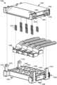
- FIG. 1is a top, isometric view of the first embodiment of the termination of the present invention
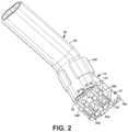
- FIG. 2is a bottom, isometric view of the termination of FIG. 1 ;
- FIG. 3is a side view of the termination of FIG. 1 ;
- FIG. 4is a bottom view of the termination of FIG. 1 ;
- FIG. 5is an exploded, isometric view of the termination of FIG. 1 ;
- FIG. 6is a side, cross-sectional view of the termination of FIG. 1 ;
- FIG. 7is an isometric view of the end of a twinaxial cable for use with the termination of FIG. 1 ;
- FIG. 8is an isometric view of an installed crimped contact for the termination of FIG. 1 ;
- FIG. 9is an isometric view of a cylindrical contact prior to installation for the termination of FIG. 1 ;
- FIG. 10is an isometric view of an installed cylindrical contact with solder opening for the termination of FIG. 1 ;
- FIG. 11is a cross-sectional view of a contact with a locking barb for the termination of FIG. 1 ;
- FIG. 12is an isometric view of a crimped contact on a shaped conductor for the termination of FIG. 1 ;
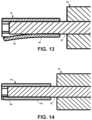
- FIG. 13is a cross-sectional view of a contact with a straight finger for the termination of FIG. 1 ;
- FIG. 14is a cross-sectional view of the contact of FIG. 13 showing the finger as it looks engaged with a device pad;
- FIG. 15is a cross-sectional view of a contact with a hooked finger for the termination of FIG. 1 ;
- FIG. 16is a cross-sectional view of a contact with a C-shaped finger for the termination of FIG. 1 ;
- FIG. 17is a top view of a contact showing important surfaces for the termination of FIG. 1 ;
- FIG. 18is a bottom view of the anchor block for the termination of FIG. 1 ;
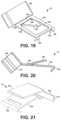
- FIG. 19is a top, isometric view of the clip for the termination of FIG. 1 ;
- FIG. 20is a side view of the clip of FIG. 19 ;
- FIG. 21is a top, isometric view of another clip for the termination of FIG. 1 ;
- FIG. 22is a cross-sectional view of a contact installed in the anchor block for the termination of FIG. 1 ;
- FIG. 23is an isometric view of a device adapted to receive four terminations for the termination of FIG. 1 ;
- FIG. 24is a top, isometric view of four terminations of FIG. 1 partially attached to the device;
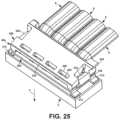
- FIG. 25is a top, isometric view of four terminations of FIG. 1 attached to the device;
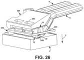
- FIG. 26is a side, cutaway view of terminations of FIG. 1 attached to the device;
- FIG. 27is a top, isometric view of a first configuration of the second embodiment of the termination of the present invention.
- FIG. 28is a top, isometric view of a second configuration of the second embodiment of the termination of the present invention.
- FIG. 29is an isometric view of the end of a twinaxial cable for use with the terminations of FIGS. 27 and 28 ;
- FIG. 30is an isometric view of a first configuration of a contact for the terminations of FIGS. 27 and 28 ;
- FIG. 31is an isometric view of a first configuration of FIG. 30 with a cable
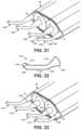
- FIG. 32is an isometric view of a second configuration of a contact for the terminations of FIGS. 27 and 28 ;
- FIG. 33is an isometric view of a cable with installed contacts of FIG. 32 ;
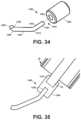
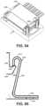
- FIG. 34is an isometric view of a third configuration of a contact for the terminations of FIGS. 27 and 28 ;
- FIG. 35is a cross-sectional view of a wire with an installed contact of FIG. 34 ;
- FIG. 36is an isometric view of a fourth configuration of a contact for the terminations of FIGS. 27 and 28 ;
- FIG. 37is an isometric view of a cable and contacts of FIG. 36 prior to installation
- FIG. 38is an isometric view of a cable with installed contacts of FIG. 36 ;
- FIG. 39is an side view of a signal conductor with an installed contact of FIG. 36 ;
- FIG. 40is an isometric view of the end of a twinaxial cable with notched wires for the contact of FIG. 36 ;
- FIG. 41is an isometric view of a fifth configuration of a contact for the terminations of FIGS. 27 and 28 ;
- FIG. 42is an isometric view of a cable with installed contacts of FIG. 41 ;
- FIG. 43is a side view of the spring finger parameters
- FIG. 44is an isometric, exploded view of a method of electrically assembling to the cable shield without drain wires for the terminations of FIGS. 27 and 28 ;
- FIG. 45is an isometric view of the contacts and clamp of FIG. 44 partially assembled to the cable
- FIG. 46is an isometric view of the contacts and clamp of FIG. 44 fully assembled to the cable
- FIG. 47is an isometric, exploded view of a shield assembly method of FIG. 44 with a membrane
- FIG. 48is an isometric view of the contacts, membrane, and clamp of FIG. 47 partially assembled to the cable;
- FIG. 49is an isometric view of the contacts, membrane, and clamp of FIG. 47 fully assembled to the cable;
- FIG. 50is an isometric, exploded view of an overmolded attachment
- FIG. 51is an isometric view of the contacts, clamp, and molding of FIG. 50 assembled to the cable;
- FIG. 52is a cross-sectional view of the contacts, clamp, and molding of FIG. 50 attached to the cable;
- FIG. 53is a bottom, isometric view of the termination of FIG. 27 ;
- FIG. 54is a side view of the termination of FIG. 27 ;
- FIG. 55is a bottom view of the termination of FIG. 27 ;
- FIG. 56is an exploded, isometric view of the termination of FIG. 27 ;
- FIG. 57is a side, cross-sectional view of the termination of FIG. 27 ;
- FIG. 58is a top view of the anchor block for the termination of FIG. 27 ;
- FIG. 59is a bottom view of the anchor block for the termination of FIG. 27 ;
- FIG. 60is a side, cross-sectional view of the anchor block for the termination of FIG. 27 ;
- FIG. 61is a bottom, isometric view of the cap for the termination of FIG. 27 ;
- FIG. 62is an isometric view of the collar for the termination of FIG. 27 ;
- FIG. 63is a top view of the collar for the termination of FIG. 27 ;
- FIG. 64is a side, cross-sectional view of the collar taken at 64 - 64 of FIG. 63 ;
- FIG. 65is an isometric view of the cable installed in the anchor block for the termination of FIG. 27 ;
- FIG. 66is a cross-sectional view of the assembly step of installing the cap for the termination of FIG. 27 ;
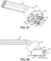
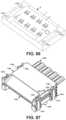
- FIG. 67is a bottom, isometric view of the termination of FIG. 28 ;
- FIG. 68is a side view of the termination of FIG. 28 ;
- FIG. 69is a bottom view of the termination of FIG. 28 ;
- FIG. 70is an exploded, isometric view of the termination of FIG. 28 ;
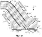
- FIG. 71is a side, cross-sectional view of the termination of FIG. 28 ;
- FIG. 72is a top view of the anchor block for the termination of FIG. 28 ;
- FIG. 73is a bottom view of the anchor block for the termination of FIG. 28 ;
- FIG. 74is a side, cross-sectional view of the anchor block for the termination of FIG. 28 ;
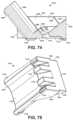
- FIG. 75is a bottom, isometric view of the cap for the termination of FIG. 28 ;
- FIG. 76is an isometric view of the collar for the termination of FIG. 28 ;
- FIG. 77is a top view of the collar for the termination of FIG. 28 ;
- FIG. 78is a side, cross-sectional view of the collar taken at 78 - 78 of FIG. 77 ;
- FIG. 79is an isometric view of the cable installed in the anchor block for the termination of FIG. 28 ;
- FIG. 80is a cross-sectional view of the assembly step of installing the cap for the termination of FIG. 28 ;
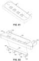
- FIG. 81is an isometric view of a device adapted to receive four terminations of FIGS. 27 and 28 ;
- FIG. 82is an exploded, isometric view of the cover and spring for four termination of FIGS. 27 and 28 ;
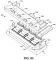
- FIG. 83is a top, isometric view of four terminations of FIGS. 27 and 28 partially attached to the device;
- FIG. 84is a top, isometric view of four terminations of FIGS. 27 and 28 attached to the device;
- FIG. 85is a side, cutaway view of terminations of FIGS. 27 and 28 attached to the device;
- FIG. 86is an isometric view of a device adapted to receive eight terminations of FIGS. 27 and 28 ;
- FIG. 87is a top, isometric view of a frame for eight termination of FIGS. 27 and 28 ;
- FIG. 88is a top, exploded, isometric view of the frame of FIG. 87 ;
- FIG. 89is a bottom, exploded, isometric view of the frame of FIG. 87 ;
- FIG. 90is a side, cross-sectional, detail view of the cover attachment for the frame of FIG. 87 ;
- FIG. 91is a side, cross-sectional view of the assembled frame of FIG. 87 ;
- FIG. 92is a top, isometric view of the frame of FIG. 87 positioned to attach to the device;
- FIG. 93is a top, isometric view of the frame of FIG. 87 partially attached to the device;
- FIG. 94is a top, isometric view of the frame of FIG. 87 fully attached to the device;
- FIG. 95is a side, cross-sectional, detail view of the frame/device attachment for the frame of FIG. 87 ;
- FIG. 96is a side, cross-sectional view of the frame of FIG. 87 fully attached to the device.
- FIG. 97is a side, cutaway view of the frame of FIG. 87 fully attached to the device.
- Described hereinis an apparatus and method for terminating a controlled-impedance cable 20 with compliant contacts that can mate directly with conductive pads and lands 4 , 5 , 6 on an electrical device 2 .
- the terminator 10 of the present inventionis for use with a controlled-impedance cable 20 .
- a cable 20has one or more signal conductors 22 , each surrounded by a dielectric 24 .
- a ground shield 26surrounds the dielectric(s) 24 .
- drain wires 30extend along the ground shield 26 .
- the term “ground shield”is used in a general way and can refer to any structure that operates as a ground shield, including but not limited to, conductive metalized wrap, foil, woven wire wraps, braids, drain wires, and/or combinations thereof.
- a sheath 28covers the ground shield 26 and drain wires 30 .
- the term, “cable”, in the present specificationrefers to a controlled-impedance cable.
- the present specificationdescribes the termination 10 of the present invention with a twinaxial (twinax) cable 20 with drain wires 30 . It is understood, however, that the termination 10 can be adapted by persons of average skill in the art to controlled-impedance cables with different numbers of the conductors and different ground structures.
- FIGS. 1 - 26Two exemplary embodiments of termination 10 are described.
- the first embodiment of the present inventionis a cable terminator 10 that employs compliant electrical contacts 34 A, 34 B (collectively, 34 ) to provide an interface between the controlled-impedance cable 20 and another electrical device 2 .
- the assembly 10is removably attached to the electrical device 2 by a compression force in a direction of compression 3 , as described below.
- the cable termination 10 of the present inventionemploys an anchor block 12 , compliant signal contacts 34 A for making the electrical connection between the signal conductors 22 and the electrical device 2 , compliant ground contacts 34 B for making the electrical connection between the ground shield 26 and the ground plane of the electrical device 2 , and a clip 14 mounted to the anchor block 12 and cable 20 .
- FIGS. 8 - 16show several configurations of a compliant contact 34 for use by the present invention.
- FIG. 8shows a simple stamped contact 34 crimped around the signal conductor 22 .
- solder or adhesivecan be used at the crimp opening 44 to facilitate bonding between the contact 34 and the signal conductor 22 .
- FIGS. 9 and 10show a cylindrical contact 34 that is slid onto the signal conductor 22 .
- the conductor 22 and contact 34are shaped to prevent rotation of the contact 34 on the conductor 22 .
- FIG. 9shows the contact 34 and conductor 22 with flat sides 38 to prevent rotation.
- the contact 34has a hole 40 in the body 36 for soldering or adhesive. After the contact 34 is slid onto the signal conductor 22 , solder or adhesive is added through the hole 40 to facilitate bonding between the contact 34 and the signal conductor 22 .
- the contact 34has a locking barb 46 .
- the locking barb 46is bent slightly, at least 5°, from the contact body 36 into the contact bore 48 and has a sharp edge 50 at the end.
- the barb 46is pushed outwardly.
- the sharp edge 50digs into the conductor 22 , preventing easy removal.
- the signal conductor 22is shaped, as at 42 in FIG. 12 , prior to installing the contact 34 .
- the shapinghelps to maintain the general size of the cross-section of the signal conductor 22 after the contact 34 is attached.
- Another benefit of shapingis to remove any coatings or platings to facilitate a more effective soldering or bonding.
- the shapingcan be done by, for example, forging, stamping, coining, drawing, or shaving.
- the shapingcan be performed with external tooling, or by the contact 34 itself as it collapses around the signal conductor 22 .
- the contact 34is formed with a spring finger 60 extending outwardly from the contact body 36 .
- additional cutsare made so that a strip can be bent away from the contact body 36 to bias outwardly to form the finger 60 .
- the bend angleis whatever angle results in the optimum balance between contact force and bending stresses in the contact material.
- the finger 60is bent away from the contact body 36 but remains generally straight.
- the finger 60deflects until the contact 34 forms a non-interrupted cylinder, as in FIG. 14 .
- the property of non-interruptionbrings the contact 34 into an optimal shape for impedance control.
- the finger 60is shaped to help reduce wear on the pads 4 , 5 on the device 2 as the finger 60 scrapes across the pad 4 , 5 when attaching and detaching.
- the finger 60has a slight hook 62 at the end.
- the finger 60has a C shape, as at 64 .
- FIG. 17indicates the face 52 of the contact 34 closest to the cable dielectric 24 and the face of the trimmed back dielectric 24 .
- the relative positions of these surfaces 52 , 54 and the length of the contact 34control the phase length of the assembly as well as how much of the contact 34 extends past the end of the conductor 22 .
- the present inventionrecognizes the need to precisely control cable length, trim, and contact position on the signal conductors 22 for optimal phase length and impedance control.
- the anchor block 12is composed of a nonconductive material and holds the compliant contacts 34 and clip 14 .
- the anchor block 12has a device surface 102 that abuts the electrical device 2 and a clip surface 104 opposite the device surface 102 to which the clip 14 is attached.
- the anchor block 12has a cable surface 106 where the cable 20 comes into the anchor block 12 and a nose surface 108 opposite the cable surface 106 .
- the anchor block 12has two sides 110 , 112 that are typically mirror images of each other. The sides 110 , 112 of the anchor block 12 are designed so that anchor blocks 12 can be placed next to each other without the need for extra spacing.
- the anchor block 12has signal contact channels 120 A and ground contact channels 120 B (collectively, 120 ) in the device surface 102 .
- the channels 120are open depressions in the device surface 102 that extend parallel to the device surface 102 .
- the channels 120are open at the cable surface 106 and extend toward the nose surface 108 to a wall 122 .
- the spacing between channels 120depends on the spacing between the corresponding signal conductors 22 and drain wires 30 of the cable 20 .
- each channel 120depends on the size of the contact 34 installed in the channel. The depth must be such that the contact spring finger 60 extends below the device surface 102 when the contact 34 is installed so that the spring finger 60 can make contact with the device pad 3 , 4 without interference from the anchor block 12 .
- the contact 34is retained in the channel 120 by a knob 128 that extends into the channel 120 from the channel front wall 122 .
- the knob 128has an enlarged head 132 at the end of a neck 134 that forms a shoulder 136 perpendicular to the channel 120 .
- the contact 34has a 900 radial lip 134 extending inwardly, as shown in FIG. 10 . When the contact 34 is pressed onto the knob 128 , the lip 134 snaps onto the knob 128 . The lip 138 abuts the shoulder 136 to retain the contact 34 on the knob 128 and in the channel 120 .
- the device surface 102 of the anchor block 12has spacing feet 142 , 144 that maintain a minimum spacing between the contact body 36 and the device 2 .
- the optimum spacingis whatever results in the minimum impedance change.
- the clip 14shown in FIGS. 19 and 20 , holds the cable 20 to the anchor block 12 , provides strain relief to the cable 20 , and provides compliant pressure for the contacts 34 against the device pads 4 , 5 .
- the clip 14has a flat body 150 , a compression arm 152 , a clamp 154 , and a hook 156 .
- the body 150lays flat against the clip surface 104 of the anchor block 12 .
- the compression arm 152is stamped out of the body 150 and bent outwardly at an angle, as at 160 .
- the bend angleis whatever angle results in a balance of an optimum downward force and stresses in the clip material.
- the downward force valueis defined as a value that overcomes the contact forces, with margin to account for pull forces, shock, and vibration encountered in the operating environment.
- the stampingleaves an opening 162 in the body 150 .
- studs 166extend outwardly from the anchor block clip surface 104 into corners 168 of the opening 162 to provide alignment and stability.
- the clamp 154extends from the rear of the clip body 150 at about a 45° angle away from the anchor block 12 .
- the clamp 154has wings 170 that extend around and securely grasp the cable 20 .
- a hook 156formed by bending the body 150 downwardly greater than 90°.
- the hook 156fits around a lip 174 protruding from the nose surface 108 adjacent to the clip surface 104 .
- the hook 156may extend across the entire width of the clip 14 or may be composed of several smaller hook elements 176 , as in FIG. 18 .
- FIG. 21An alternate clip 14 is shown in FIG. 21 .
- the cable 20is first prepared by trimming back the sheath 28 , ground shield 26 , and dielectric 24 to expose the signal conductor 22 and, if available, the drain wires 30 , as in FIG. 7 .
- the compliant signal contacts 34 Aare attached to the exposed signal conductors 22 and compliant ground contacts 34 B are attached to the exposed drain wires 30 .
- “permanently attached”means non-separable, for example, crimping, soldering, gluing, welding, and coining.
- the cable trimming and contact positioningis controlled to provide more precise phase and impedance matching.
- the contacts 34are inserted into the appropriate channels 120 and pushed toward the nose surface 104 until the contacts 34 snap into the knobs 128 .
- the clip 14is installed onto the anchor block 12 by placing the hook 156 over the anchor block lip 174 and pivoting the clip body 150 downwardly until the studs 166 are within the opening corners 168 .
- the cable 20is bent until it touches the clamp 154 and the wings 170 are bent around and cinched to the cable sheath 28 .
- the contacts 34snapped onto the knobs 128 and the clamp 154 pulling the cable 20 upwardly secure the cable 20 and contacts 34 in the anchor block 12 to hold the termination assembly 8 together.
- FIGS. 23 - 26show how four of the termination assemblies 8 of FIG. 1 are attached to a device 2 .
- FIG. 23shows a section of device 2 with pads 4 , 5 for attachment by four adjacent twinax termination assemblies 8 . Note the spacing between adjacent termination sections 6 , that is, between two adjacent ground pads 5 , is no larger than the spacing between a signal pad 4 and its adjacent ground pad 5 . This is possible because the anchor blocks 12 are designed to be placed adjacent to one another without needing extra space therebetween.
- the termination assemblies 8are removably attached to the device 2 by a frame 200 that comprises a lattice 202 and a cover 204 .
- the lattice 202has a body 210 and feet 212 that attach to the device 2 with the body 210 spaced from the device 2 .
- the feet 212attach to the device 2 by surface-mount soldering but the present invention contemplates that the feet 212 can be attached using any practical method.
- the body 210 of the lattice 202has a cutout 220 into which the termination assemblies 8 are inserted.
- the cutout 220is positioned such that the termination assemblies 8 are in the correct position over the pads 4 , 5 .
- the cover 204attaches to the ends of the lattice 202 as described below to hold the termination assemblies 8 against the device 2 in the direction of compression 3 .
- the cover 204has a body 224 that spans the termination assemblies 8 .
- One end of the cover 204is pivotally attached to one end of the lattice 202 .
- a cylindrical pin 226 on the cover 204snaps into a corresponding tubular socket 228 on the lattice 202 so that the pin 226 rotates in the socket 228 .
- the other end of the cover 204has a cylindrical bar 234 that snaps into a concave, semicylindrical receptacle 236 .
- the cover body 204has key holes 240 into which tabs 242 on the clip surface 104 of the terminations 10 fit. Alternatively, tabs on the bottom of the cover body fit into holes in the clip surface 104 of the terminations 10 .
- the tabs 242 /holes 240help to maintain the correct positioning of the terminations 10 .
- the terminations 10To install the terminations 10 , they are placed in the appropriate manner in the cutout 220 . The cover 204 is pivoted downwardly until the bar 234 snaps into the receptacle 236 . At this point, the cover 204 is pushing down on the compression arm 152 of the clip 14 , compressing the terminations 10 against the device 2 . To remove the terminations 10 , an opening tab 244 on the bar end of the cover 204 is pulled up to release the bar 234 from the receptacle 236 .
- the termination 10 of the present inventionprovides compliance in two independent ways.
- the contact springs 60provide compliance at the device pads 4 , 5 , in part, to adjust for any non-planarities on the surface of the device 2 .
- the clip compression arm 152provides compliance for each of the termination assemblies 8 when compressed to the device 2 by the frame cover 204 .
- the second embodiment of present inventionis a cable terminator 1010 that employs compliant electrical contacts 1030 A, 1030 B (collectively, 1030 ) to provide an interface between the controlled-impedance cable 20 and another electrical device 2 .
- the terminator 1010is removably attached to the electrical device 2 by a compression force in a direction of compression 3 as described below.
- the direction of compression 3is the direction that is perpendicular to the surface 1 of the device 2 , as shown in FIGS. 85 and 96 .
- the second embodimentcomes in a first configuration 1010 A shown in FIGS. 27 and 53 - 66 and a second configuration 1010 B shown in FIGS. 28 and 67 - 80 .
- Both configurationsemploy a housing 1018 that includes an anchor block 1012 , a cap 1014 for securing the cable 20 to the anchor block 1012 , and a collar 1016 for securing the cap 1014 to the anchor block 1012 .
- compliant signal contacts 1030 Afor making the electrical connection between the signal conductors 22 and the electrical device 2
- compliant ground contacts 1030 Bfor making the electrical connection between the ground shield 26 and the ground plane 9 of the electrical device 2 are attached to the cable 20 .
- the contactsare installed on a cable 20 like that shown in FIG. 29 .
- the cable 20is shown in the figures as a twinax cable, the present invention is not limited to a twinax cable and may be employed with cables having one or more signal conductors.
- the cable 20is prepared by trimming back the sheath 28 , ground shield 26 , and dielectric 24 to expose the ends of the signal conductors 22 and, if available, the drain wires 30 .
- the length of the exposed signal conductorsis determined by the compliant contact 30 that is used.
- the first configuration 1186 of a compliant contact 1030 for use by the present inventionis shown in FIGS. 30 - 31 .
- the contact configuration 1186is the exposed end of the conductor 22 formed into a contact.
- the end of the signal conductor 22is bent toward the conductor axis 1060 , as at 1196 , to form a spring finger 1188 extending outwardly at an angle to a tip 1190 .
- the parameters of the spring finger 1188 and the bend angle 1196are discussed below.
- the tip 1190 of the spring finger 1188is bent, as at 1192 , to form a curved contact point 1194 , in part to reduce wear on the device 2 .
- Methods for forming the contact 1186are well-known in the art and the any method that is appropriate for the material and the desired shape may be used. Methods can include bending, punching, coining, swaging, spanking, chamfering, and shearing.
- this contact 1186is that, since it is formed from the conductor 22 itself, there is no additional attachment that will affect the impedance. Also, the cylindrical shape of the conductor 22 is continued throughout the length of the contact 1186 , making it easier to maintain impedance.
- the remainder of the contact configurationsare separate components that are attached to the end of the conductor 22 .
- a separate componentmay be necessary when the material from which the conductor 22 is composed does not have the mechanical characteristics needed for the particular application.
- a separate componentcan be made of a more appropriate material or combination of materials.
- a second configuration 1170 of a compliant contact 1030is shown in FIG. 32 .
- the contact configuration 1170is a cylindrical, formed wire contact with a body 1172 .
- a spring finger 1174extends outwardly from the body 1172 at a bend 1184 to a tip 1176 .
- the parameters of the spring finger 1174 and the bend angle 1184are discussed below.
- the tip 1176 of the spring finger 1174is bent, as at 1178 , to form a curved contact point 1180 , in part to reduce wear on the device 2 .
- the opposite end of the contact body 1172is a conical attachment 1182 that is at an angle to the contact body 1172 .
- the end of the attachment 1182is shaped to bond directly to the conductor 22 after the cable 20 is trimmed back, as in FIG. 33 , by weld, solder, adhesive, or any other adequate attachment means.
- the attachment 1182is shaped to extend into a bore in the conductor 22 . The only stipulation is that the bending stress should only be transmitted to the contact 1170 and not to the softer cable conductor 22 .
- This contact 1170is that the cylindrical shape of the conductor 22 is continued throughout the length of the contact 1170 , making it easier to maintain impedance.
- Cable wire materialsare selected mainly for their electrical properties, such as conductivity. Contact materials need to have good mechanical and electrical properties.
- the wire material of the contact 1170can be any material with spring properties but also good electrical properties. If it is an expensive material, only the last millimeter of the electrical path, the finger tip 1176 , needs to be made from of it. The rest of the contact 1170 can be made of the standard cable wire material.
- a third configuration 1250 of a compliant contact 1030is shown in FIG. 34 .
- the contact configuration 1250is a cylindrical, formed wire contact with a body 1252 .
- a spring finger 1254extends outwardly from the body 1252 from a bend 1272 to a tip 1256 .
- the parameters of the spring finger 1254 and the angle of the bend 1272are discussed below.
- the tip 1256 of the spring finger 1254is bent, as at 1258 , to form a curved contact point 1260 , in part to reduce wear on the device 2 .
- the attachment 1262has a tail 1264 that is at an angle to the contact body 1252 .
- a collar 1266attaches the tail 1264 to the conductor 22 .
- the collar 1266is cylindrical with an axial bore 1268 at one end for the tail 1264 and an axial bore 1270 at the other end for the conductor 22 , as shown in FIG. 35 .
- the tail 1264is inserted into the tail bore 1268 and the conductor 22 is inserted into the wire bore 1270 after the cable 20 is trimmed back.
- the tail 1264 and conductor 22are bonded to the collar 1266 using any adequate method, including by weld, solder, or adhesive.
- a fourth configuration 1034 of a compliant contact 1030is shown in FIGS. 36 - 39 .
- the contact configuration 1034has a rectangular contact body 1036 with a pair of tines 1050 .
- the tines 1050are initially planar with the body 1036 and are bent approximately 90° from the body 1036 , as at 1052 , to form a fork 1054 perpendicular to the body 1036 .
- the contact 1034is attached to the exposed signal conductor 22 .
- the fork 1054holds onto the conductor 22 by pushing the wire into the gap 1056 between the tines 1050 to the body 1036 , as in FIG. 38 .
- the gap 1056is slightly smaller than the diameter of the conductor 22 , so the conductor 22 fits tightly in the gap 1056 .
- the size of the fork gap 1056is designed for the diameter of the conductor 22 with which the contact 1034 is to be used.
- the body 1036is generally paraxially aligned with the conductor 22 , as in FIG. 39 .
- a spring finger 1038extends from the body 1036 and signal conductor 22 at a bend 1040 to a tip 1042 .
- the parameters of the spring finger 1038 and the bend angle 1058are discussed below.
- the spring finger 1038can be shaped like a truncated cone.
- the tip 1042 of the spring finger 1038is bent, as at 1044 , to form a curved contact point 1046 , in part to reduce wear on the device 2 .
- the spring finger 1038provides compliance by its ability to bend toward the signal conductor axis 1060 .
- the signal conductor 22is notched, as at 32 in FIG. 40 , to facilitate easier installation of the contact 1034 .
- solder or adhesivecan be used in the gap 1056 to facilitate bonding between the contact 1034 and the conductor 22 .
- the cable trimming and positioning of the contacts 1034 on the signal conductors 22is controlled to provide more precise phase and impedance matching.
- FIG. 41shows a fifth configuration 1154 of a compliant contact 1030 .
- the contact configuration 1154has a rectangular contact body 1156 .
- a spring finger 1158extends outwardly from one edge of the body 1156 at a bend 1168 to a tip 1160 .
- the parameters of the spring finger 1158 and the angle of the bend 1168are discussed below.
- the tip 1160 of the spring finger 1158is bent, as at 1162 , to form a curved contact point 1164 , in part to reduce wear on the device 2 .
- the opposite end of the contact body 1156is at an angle to the contact body 1156 .
- the endhas an attachment 1166 that is perpendicular to the end of the conductor 22 so as to bond directly to the conductor 22 after the cable 20 is trimmed back, as in FIG. 42 , by weld, solder, adhesive, or any other adequate attachment means.
- the parameters of the spring fingerare shown in FIG. 43 , using the reference numerals of the configuration of FIG. 36 .
- the angle 1058 of the spring finger 1038 from the axis 1060 of the signal conductor 22depends on the angle 1024 of the signal conductor 22 to the device 2 and the amount of compliance that is desired in the spring finger 1038 .
- the bend angle 1058can be in the range of from 90° to 270°. In FIG. 43 , the bend angle 1058 is approximately 140°.
- the length 1020 of the spring finger 1038is determined by several factors. The longer the spring finger 1038 , the greater the compliance, all other parameters being equal. However, it also means a greater loss of signal integrity. The greater the angle 1022 of the spring finger 1038 relative to the device 2 prior to installation, the greater the compliance because the spring finger 1038 can displace more before the termination is secured against the device surface 1 .
- the spring finger displacement 1026that is, the distance that the contact point 1046 can move is in the range of from 0.002 inches to 0.020 inches, with a preferred range of from 0.003 to 0.010 inches, and an optimal displacement of about 0.006 inches.
- drain wires 30can be used with drain wires 30 .
- another methodis needed to provide electrical contact with the cable shield 26 .
- the signal conductors 22use a compliant contact 1030 A as described above.
- the ground contacts 1030 Bare elements of a clamp 1280 that is secured around the cable shield 26 .
- the clamp 1280is stamped from a sheet of conductive material, typically metal.
- the elongated body 1282has wings 1284 that bend around the cable shield 26 .
- Contact appendages 1286extend from the wings 1284 at the outer sides of the shield 26 .
- the ground contacts 1030 Bare formed from the appendages 1286 .
- the contact body 1288extends from the appendage 1286 .
- a spring finger 1290extends outwardly at an angle from the body 1288 . The angle is within a range that results in a differential impedance of 100 ⁇ 5 ohms, with a preferred angle of approximately 140°.
- the spring finger 1290is shaped like a truncated cone.
- the tip 1294 of the spring finger 1290is bent, as at 1296 , to form a curved contact point 1298 in order to reduce wear on the device 2 .
- the signal contacts 1030 Aare attached to the exposed signal conductors 22 as described above and the clamp 1280 is secured around the exposed shield 26 .
- the cable 20is placed on the clamp body 1282 between the wings 1284 , as in FIG. 45 , and the wings 1284 are bent around the shield 26 to secure the clamp 1280 to the shield 26 , as in FIG. 46 . It is necessary to make sure that the ground contacts 1030 B are aligned properly with the signal contacts 1030 A.
- the clamp 1280has a burr on one side.
- the present inventioncontemplates using the burr to more securely attach the clamp 1280 to the cable 20 .
- the wings 1284are bent such that the cable 20 is placed on the burr side of the clamp body 1282 . When the wings 1284 are bent around and secured to the shield 26 , the burr digs into the shield 26 slightly to provide additional grip to the attachment.
- the clamp 1280can be more securely attached by the use of adhesives, welding, soldering, or the like.
- a membrane 1304is installed on the cable shield 26 prior to installing the signal contacts 1030 A and the clamp 1280 .
- the membrane 1304is a flexible sheet with or without a plurality of through holes 1306 .
- the membrane 1304is composed of an electrically conductive material, for example, conductive metal or metal mesh, conductive rubber, EMI foam, and conductive tape. The membrane 1304 can be used to distribute the clamping forces and to increase the contact surface area.
- the cable 20 sheath 28is trimmed back such that the length of exposed shield 26 is at least that of the length of the membrane 1304 . This is to prevent the membrane 1304 from overlapping the sheath 28 when installed.
- the membrane 1304is wrapped around the exposed shield 26 .
- the signal contacts 1030 Aare attached to the exposed signal conductors 22 as described above and the clamp 1280 is secured around the membrane 1304 .
- the cable 20 with the membrane 1304is placed on the clamp body 1282 between the wings 1284 and the wings 1284 are bent around the membrane 1304 to both secure the clamp 1280 to the membrane 1304 and to secure the membrane 1304 to the shield 26 . It is necessary to make sure that the ground contacts 1030 B are aligned properly with the signal contacts 1030 A.
- the clamp 1280is covered by a conductive or nonconductive polymer using injection insert molding.
- the assembly comprised of the cable 20 , compliant signal contacts 1030 A, and clamp 1280are clamped by two die halves and molten plastic is injected around the entire assembly.
- the plastic molding 1308adds strain relief, but also protects the mechanical joint between the clamp 1280 and shield 26 from external forces and from corrosion.
- the molding 1308if conductive, can also strengthen the electrical connection between the clamp and shield 26 .
- the molding 1308is shown with the cable 20 and clamp 1280 .
- the molding 1308can also be used with the membrane 1304 .
- the molding 1308can also be used with compliant ground contacts 1030 B instead of the clamp 1280 .
- the housing 1018 of both configurations of the second embodimentincludes an anchor block 1012 , a cap 1014 , and a collar 1016 .
- the anchor block 1012is composed of an electrically nonconductive material and, together with the cap 1014 and collar 1016 , holds the compliant contacts 1030 and cable 20 in the desired orientation to the device 2 .
- the illustrated anchor blocks 1012 and caps 1014are designed for the fourth contact configuration 1034 , but is well within the ability of a person of skill in the art to adapt them for the various other contact configurations described above.
- the anchor block 1012has a device surface 1070 that abuts the electrical device 2 and a cap side 1072 opposite the device surface 1070 .
- the cap side 1072has a cable tray 1074 to which the cable 20 is secured by the cap 1014 and collar 1016 .
- the two configurationsdiffer in how the cap 1014 is attached to the anchor block 1012 , as described below.
- the anchor block 1012has a front wall 1076 and a back wall 1078 . Between the front wall 1076 and back wall 1078 are two sides 1080 , 1082 that are designed so that anchor blocks 1012 can be placed next to each other without the need for an inordinate amount of spacing.
- a cable tray 1074extends rearwardly and upwardly at an angle 1084 from a depression 1068 in the anchor block 1012 .
- the angle 1084 of the cable tray 1074depends on the desired angle of the cable 20 to the device surface 1 . In the illustrated design, the angle 1084 is about 52°, but may be more or less depending on the particular application.
- the upper cable surface 1086is designed to maintain the cable's differential impedance, typically 95 ⁇ 10 ohms.
- the cable surface 1086is curved in the lateral direction, as at 1088 , such that the cable 20 fits longitudinally into the cable surface 1086 .
- a flat cable stop 1090At the bottom end of the cable surface 1086 within the depression 1068 is a flat cable stop 1090 generally perpendicular to the angle of the cable surface 1086 .
- the free edge 1092 of the stop 1090has a notch 1094 for each of the signal conductors 22 .
- a notch 1096 for a drain wire 30At each side of the stop 1090 is a notch 1096 for a drain wire 30 .
- Each notch 1094 , 1096has a floor 1100 at approximately the same angle to the device surface 1070 as the cable surface 1086 . Walls 1102 extend perpendicularly from the floor 1100 . The width of the notch 1094 , 1096 , that is, the distance between the notch walls 1102 , is the approximately same as the width of the contact 1034 at the tines 1050 , as explained below.
- Each signal notch 1094extends downwardly into a signal contact aperture 1110 and each drain wire notch 1096 extends downwardly into a ground contact aperture 1112 .
- the apertures 1110 , 1112are through openings to the device surface 1070 .
- the apertures 1110 , 1112are at approximately the same angle to the device surface 1070 as the cable surface 1086 .
- the spacing between apertures 1110 , 1112depends on the spacing between the corresponding signal conductors 22 and drain wires 30 .
- Each aperture 1110 , 1112has an opening 1114 in the device surface 1070 .
- the opening 1114extends in the direction from the back wall 1078 to front wall 1076 , as seen in FIG. 59 , and is longer and wider than the spring finger 1038 of the contact 1034 .
- a cap wall 1106Extending upwardly and forwardly from the apertures 1110 , 1112 to the front wall 1076 is a cap wall 1106 , which forms the front of the depression 1068 .
- the cap wall 1106is at approximately 90° to the cable surface 1086 , but this angle is not critical and can be within a wide range.
- the device surface 1070 of the anchor block 1012has spacing feet 1120 , 1122 that maintain a spacing between the device surface 1070 and the device.
- a preferred valueis 0.005 inch.
- the present designuses three spacing feet 1120 , 1122 because three points define a plane. This ensures the anchor block 1012 will seat appropriately on device 2 regardless of its curvature. A different number of feet may result in rocking.
- the cap 1014clamps the cable/contacts assembly to the anchor block 1012 .
- the cap 1014fits into the anchor block depression 1068 .
- the cap 1014has a cable clamp 1128 that complements the cable tray 1074 of the anchor block 1012 .
- the bottom surface of the cable clamp 1128is the cable clamp surface 1130 and is curved in the lateral direction, as at 1140 , in the same manner as the cable tray cable surface curve 1088 .
- the contact clamp surface 1132which is a flat surface that is the length of the notches 1094 , 1096 .
- the contact clamp surface 1132encloses the notches 1094 , 1096 .
- an anchor block surface 1134Extending upwardly and forwardly from the contact clamp surface 1132 is an anchor block surface 1134 that abuts the cap wall 1106 of the anchor block 1012 .
- the cable 20is trimmed back.
- the signal contacts 1030 Aare attached to the signal conductors 22 and the ground contacts 1030 B are attached to the drain wires 30 as described above.
- the collar 1016is slid over the end of the cable 20 .
- the collar 1016shown in FIGS. 62 - 64 and FIGS. 76 - 78 , is a circular ring composed of a rigid material, typically a metal.
- the inside edge 1146is optionally beveled to facilitate installation.
- the contacts 1034are inserted into the notches 1094 , 1096 and the cable 20 is laid in the curve 1088 of the cable tray cable surface 1086 , pushing the cable 20 into the anchor block 1012 until the cable dielectric 24 is against the cable stop 1090 , as in FIG. 65 .
- the contact tines 1050are wedged into the notch 1094 , 1096 between the walls 1102 , as well as the contact tines 1050 .
- the resulting assemblyadds pull strength to the cable 20 .
- the contact spring fingers 1038are extending along the aperture openings 1114 and from the device surface 1070 , as in FIG. 55 .
- the cap 1014is installed on the anchor block 1012 . As mentioned above, this is how the two configurations 1010 A, 1010 B differ.
- the anchor block 1012has a lateral hook groove 1108 in the cap wall 1106 and the cap 1014 has a lateral hook ridge 1136 in the anchor block surface 1134 .
- the cap 1014is installed by placing the cap 1014 in the anchor block depression 1068 with the hook ridge 1136 against the cap wall 1106 , as in FIG. 66 .
- the cap 1014is pushed downwardly into the depression 1068 , as at 1150 , until the hook ridge 1136 snaps into the hook groove 1108 .
- the cable clamp surface 1130is laying on the cable 20 and the contact clamp surfaces 1132 are covering the notches 1094 , 1096 , as in FIG. 57 .
- the front of the cap side wall 1320is notched, as at 1322 , and forms a shoulder 1324 that is perpendicular to the anchor block surface 1134 .
- the side wall 1326 of the anchor block depression 1068has a complementary shoulder 1328 .
- the cap 1014is installed by placing the heel 1144 of the cap anchor block surface 1134 against the cap wall 1106 of the anchor block depression 1068 .
- the cap 1014is pushed into the anchor block depression 1068 toward to cable 20 , as at 1332 in FIG. 80 , until the cap shoulder 1324 snaps into the depression shoulder 1328 .
- the cable clamp surface 1130is laying on the cable 20 and the contact clamp surfaces 1132 are covering the notches 1094 , 1096 , as in FIG. 71 .
- the collar 1016is slid down around the cable tray 1086 and cap cable clamp 1128 until the collar 1016 snaps under a lip 1098 at the upper edge of the cable tray 1086 and a corresponding lip 1138 at the upper edge of the cap cable clamp 1128 . Because the collar 1016 is rigid, it does not deform to snap under the lips 1098 , 1138 . The nature of the construction of the controlled-impedance cable 20 causes it to compress slightly as the collar 1016 is sliding over the lips 1098 , 1138 , thereby providing the deformation need to assemble the termination.
- the cable tray cable surface 1086 and the cap cable clamp surface 1130are textured to provide friction against the cable sheath 28 to act as a strain relief.
- FIGS. 81 - 85show an embodiment of how four termination assemblies 1008 of the second embodiment can be attached to a device 2 .
- FIG. 81shows a section of the device 2 with signal pads 4 and a ground plane 9 for attachment by four adjacent twinax termination assemblies 1008 .
- the termination assemblies 1008are removably attached to the device 2 by a frame 1200 that is comprised of a lattice 1202 and a cover 1204 , as shown in FIG. 83 .
- the lattice 1202has a generally rectangular body 1210 and pegs 1214 .
- the lattice 1202attaches to the device 2 via through-hole solder joints between the pegs 1214 and peg holes 7 in the device 2 .
- the pegs 1214can have an interference fit in corresponding peg holes 7 in the device 2 .
- the lattice body 1210has a rectangular cutout 1212 into which the termination assemblies 1008 are inserted.
- the cutout 1212is positioned such that the termination assemblies 1008 are in the correct position over the pads 4 .
- the cover 1204attaches to the ends of the lattice 1202 , as described below, to hold the termination assemblies 1008 against the device 2 in the direction of compression 3 .
- the cover 1204is composed of a body 1220 that spans the termination assemblies 1008 and a spring set 1224 .
- the spring set 1224has an elongated body 1226 and a cantilever spring 1228 extending from and curled under the body 1226 for each termination 1008 .
- the spring set 1224can be a stamped metal part.
- the spring set 1224can be insert-molded into the body 1220 .
- the cover spring 1224can be mechanically attached to body 1220 using interference fits.
- the ends of the cover 1204include slots 1222 that slide onto the pegs 1214 extending upwardly from the lattice 1202 .
- the attachmentcan involve an interference fit between the pegs 1214 and the slots 1222 , but can also use other vertical or horizontal joining methods such as snap clips or dovetail joints.
- Each spring 1228pushes its corresponding termination assembly 1008 against the device surface 1 in the direction of compression 3 perpendicular to the device surface 1 , as shown in FIG. 85 .
- the spring 1228pushes down on the spring surface 1142 of the cap 1014 .
- the through-hole solder joining processcan result in uneven seating of the frame 1200 on the device 2 .
- the device 2can be warped or thin and not rigid.
- the stroke of the spring 1228is designed to be long enough to overcome these imperfections.
- the compression force provided by the spring 1228is designed to overcome the combined spring force from all of the contacts 1034 with some margin to account for external forces, moments, vibration, and shock exerted on the cable 20 during normal operation.
- the terminations 1008have independent compliance, meaning they are spring-loaded from above so that a change in relative seating height from termination 1008 to termination 1008 in the device 2 due to device manufacturing imperfections or imperfect seating of the frame 1200 on the device 2 does not impact the differential impedance of the interconnect.
- the terminations 1008are not permanently attached to the frame 1200 . They can be attached and detached and moved to different locations. Further, the frame 1200 at one location does not have to be the same shape as the frame 1200 at other locations. This approach makes the design of the present invention more versatile than other commercially available connectors because the frame 1200 can be any shape or size.
- final testing of the termination 1008will always involve only four instrumentation ports because only one differential channel needs to be tested at a time.
- Other commercially available connectorshave a multitude of permanently attached cables, so each unit needs four instrumentation ports per cable for testing.
- FIGS. 86 - 97show an embodiment of how eight termination assemblies 1008 of the second embodiment can be attached to a device 2 .
- FIG. 86shows a section of the device 2 with signal pads 4 and a ground plane 9 for attachment by eight twinax termination assemblies 1008 arranged in two offset rows of four termination assemblies 1008 .
- Peg holes 7provide for alignment, as described below.
- the termination assemblies 1008are removably attached to the device 2 by a frame 1340 that is comprised of a lattice 1342 and a cover 1344 .
- the lattice 1342is generally rectangular and has cutouts 1350 into which the termination assemblies 1008 are inserted. Each cutout 1350 accepts an assembly 1008 through an opening 1352 in the top and the cutout 1350 is sized such that the assembly 1008 fits snuggly within the cutout 1350 .
- the compliant contacts 1030extend through an aperture 1356 in the bottom 1362 of the lattice 1342 .
- the cable 20extends along the top 1358 of and out one side 1360 of the lattice 1342 .
- the cutouts 1350are arranged such that the compliant contacts 1030 are aligned over the pads 4 and ground plane 9 when the frame 1340 is attached to the device 2 .
- Alignment pegs 1348extend from the bottom 1362 of the lattice 1342 .
- the cover 1344secures the assemblies 1008 in the lattice 1342 .
- the cover 1344is generally flat so that it can lay on the assemblies 1008 .
- the cover 1344has channels 1364 for the cables 20 .
- the cover 1344has posts 1366 extending from the bottom 1368 , each of which is aligned with a cutout 1350 .
- a coil spring 1370sits on the post 1366 and, when the cover 1344 is installed on the lattice 1342 , pushes against the cap spring surface 1142 of the assembly 1008 to bias the assembly 1008 against the cutout floor 1354 so that the compliant contacts 1030 extend from the floor apertures 1356 .
- the cover 1344attaches to the lattice 1342 by clips 1374 extending from the corners of the lattice 1342 .
- the clips 1374are L-shaped digits with a right-angle finger 1376 and that can flex outwardly.
- the cover 1344has a flange 1378 within a notch 1384 at each corner.
- Each flange 1378has a beveled lower surface 1380 and a flat upper surface 1382 .
- the cover 1344is placed on the clips 1374 so that the clips 1374 are aligned with the flange notches 1384 .
- the cover 1344is pushed into the clips 1374 , the beveled lower surface 1380 of the flanges 1378 force the clips 1374 outwardly.
- the notches 1384maintain alignment between the lattice 1342 and the cover 1344 .
- the clips 1374snap inwardly so that the flat bottom surface 1382 of the fingers 1376 abut the flat upper surface 1382 of the flanges 1378 , thereby preventing removal of the cover 1344 .
- the cover 1344can be removed by manually pulling the clips 1374 away from the flanges 1378 .
- the frame 1340is removably attached to the device 2 by clips 1390 mounted to the device 2 , as in FIG. 92 .
- the clips 1390shown in FIG. 95 , are generally L-shaped with a base 1392 against the device 2 and an arm 1394 extending approximately perpendicularly away from the base 1392 .
- At end of each arm 1394is a finger 1414 that curves inwardly and downwardly to a free edge 1416 .
- the clip base 1392has two or more fingers 1410 bent at right angles to the base 1392 . The fingers 1410 go into plated through holes 1412 in the device 2 and are soldered to the plating.
- the through-hole solder joining processtakes advantage of existing pick and place equipment and reflow ovens to easily and quickly install components like these clips 1390 onto the device 2 . Since the clips 1390 are not part of the termination 10 , they can go through the reflow process without exposing the cables 20 in the termination 10 to excessive temperatures.
- the cover 1344has a rail 1400 within an elongated notch 1402 at each short end 1398 .
- Each rail 1400has a beveled lower surface 1404 and an upper surface 1406 that is angled slightly upwardly away from the cover 1344 .
- cover 1344is placed on the clip arms 1394 so that the clip arms 1394 are aligned with the rail notches 1402 and the alignment pegs 1348 are aligned with the peg holes 7 .
- the cover 1344is pushed into the clips 1390 , the beveled lower surface 1404 of the rails 1400 force that clip arms 1394 outwardly.
- the notches 1402maintain alignment between the frame 1340 and the device 2 .
- the clip arms 1394snap inwardly so that the free end 1416 of the fingers 1414 abut the upper surface 1406 of the rails 1400 , thereby preventing removal of the frame 1340 from the device 2 .
- the slight angle of the upper surface 1406prevents the clip finger 1414 from slipping off of the rail 1400 .
- the frame 1340can be removed by manually pulling the clip arms 1394 away from the rails 1400 .
Landscapes
- Details Of Connecting Devices For Male And Female Coupling (AREA)
- Coupling Device And Connection With Printed Circuit (AREA)
Abstract
Description
This application is a continuation of U.S. patent application Ser. No. 17/061,230 (now U.S. Pat. No. 11,205,877), filed on Oct. 1, 2020, entitled “CONTROLLED-IMPEDANCE COMPLIANT CABLE TERMINATION,” which is a continuation of International Application No. PCT/US2019/025426, filed on Apr. 2, 2019, entitled “CONTROLLED-IMPEDANCE COMPLIANT CABLE TERMINATION,” which claims priority to and the benefit of U.S. Provisional Application Ser. No. 62/795,788, filed on Jan. 23, 2019. International Application No. PCT/US2019/025426 also claims priority to and the benefit of U.S. Provisional Application Ser. No. 62/651,467, filed on Apr. 2, 2018. The entire contents of these applications are incorporated herein by reference in their entirety.
The purpose of a cable termination is to provide an interconnect from a cable to an electrical device and to provide a separable electrical interconnection between the cable and its operating environment. The characteristic of separability means that the cables are not interconnected by permanent mechanical means, such as soldering or bonding, but by temporary mechanical means.
Currently, cables are terminated using a conventional-type connector which is also controlled-impedance, such as a male/female pair connectors that have one piece soldered to the operating environment, such as a printed circuit board (PCB), and one piece soldered, crimped, or otherwise permanently fastened to the wire end. In other cases, the connector or the cables are soldered to a different PCB which is then separably connected to the working environment such as another PCB. The two PCBs are then attached with a compression interconnect interposer. While being generally the same impedance environment as the cable, there are impedance mismatches which cause high-frequency attenuation at the point of interface between the cable and the PCB's, and the connector and its working environment, such as like a PCB. Additionally, these cable terminations often require through holes in PCBs for mounting and, consequently, it can be difficult to design the best possible controlled-impedance environment. These types of cable terminations have generally long transitions and thus introduce more signal reflections which can inhibit higher frequency signals.
Another form of prior art is a system which uses two independent parts to mate several cables to its electrical environment. This system uses one part that is generally soldered to a printed circuit board and another part that is generally mated to several cables. The two pieces can be plugged together to form the controlled-impedance interconnection. These systems are better-controlled impedance environments but are limited by the signal integrity of the electrical path since the two mated parts require a relatively long change in the transmission line which can cause reflections and limit bandwidth of the system.
Still another prior art is a connector which terminates controlled-impedance cables to connectors which use compliant “pins” to press into holes in a planar device such as a PCB. These holes are generally required to be large which can also limit bandwidth of the system.
The present invention is an apparatus and method for terminating a controlled-impedance cable with compliant contacts that can mate directly with conductive pads and lands on an electrical device. The terminator is for use with a controlled-impedance cable with one or more signal conductors, each surrounded by a dielectric. A ground shield with optional drain wires surrounds the dielectric(s) and a sheath covers the ground shield and drain wires.
Two exemplary embodiments oftermination 10 are described.
The first embodiment employs an anchor block, compliant signal contacts for the signal conductors, compliant ground contacts for the ground shield, and a clip mounted to the anchor block and cable. The compliant contacts can have one or more of a number of different configurations. Each configuration has a spring finger that extends outwardly from the body of the contact.
The nonconductive anchor block holds the compliant contacts and clip. The anchor block has a cable surface where the cable comes into the anchor block and signal contact channels and ground contact channels in the surface that abuts the device. The contact is retained in the channel by a knob that extends into the channel from the channel front wall.
The clip holds the cable to the anchor block, provides strain relief to the cable, and provides compliant pressure for the contacts against the device. The clip has a flat body, a compression arm, a clamp, and a hook. The clamp extends from the rear of the clip body at about a 45° angle away from the anchor block. The clamp has wings that extend around and securely grasp the cable.
To assemble the termination to a cable, the cable is first prepared by trimming back the sheath, ground shield, and dielectric to expose the signal conductor and, if available, the drain wires. The compliant signal contacts are attached to the exposed signal conductors and compliant ground contacts are attached to the exposed drain wires. The contacts are inserted into the appropriate channels and pushed toward the nose surface until the contacts snap into the knobs. The clip is installed onto the anchor block by placing the hook over the anchor block lip and pivoting the clip body downwardly. The cable is bent until it touches the clamp and the wings are bent around and cinched to the cable sheath.
The termination assemblies are removably attached to the device by a frame that comprises a lattice and a cover. The body of the lattice has cutouts into which the termination assemblies are inserted. The cover has a body that spans the termination assemblies. One end is pivotally attached to the lattice. The other end snaps into a receptacle.
The terminations are placed in the cutouts. The cover is pivoted downwardly until the end snaps into the receptacle. The cover pushes down on the compression arms of the clips, compressing the terminations against the device.
The second embodiment comes in two configurations, both of which employ a housing that includes an anchor block, a cap for securing the cable to the anchor block, and a collar for securing the cap to the anchor block. Compliant signal contacts make the electrical connection between the signal conductors and the device and compliant ground contacts make the electrical connection between the ground shield and the ground plane of the device.
A number of different configurations for the contact are described for use with the present invention. The configurations are applicable to both the signal conductors and drain wires. In a first configuration, the contact is the exposed end of the conductor formed into a contact with a spring finger. In the second configuration, the contact is a cylindrical, formed wire contact with a body and a spring finger extending outwardly from the body. The contact is bonded directly to the end of the signal conductor. In the third configuration, the contact is a cylindrical, formed wire contact with a body and a spring finger extending outwardly from the body. The contact is attached to the signal conductor by a collar. In the fourth configuration, the contact has a rectangular contact body with a pair of tines bent 90° from the body to form a fork that holds onto the signal conductor by pushing the wire into the gap between the tines. A spring finger extends outwardly from the body. In the fifth configuration, the contact has a rectangular body with a spring finger extending outwardly from one edge of the body. The other end of the body is at an angle to the body and bonded directly to the end of the signal conductor.
When there are no drain wires, the ground contacts are elements of a clamp that is secured around the cable shield.
The housing of both configurations includes an anchor block, a cap, and a collar. The anchor block has a cable tray that extends rearwardly and upwardly at the desired angle of the cable to the device surface. The anchor block has a notch for each of the signal conductors and a notch for each drain wire. Each notch extends downwardly into a contact aperture, which are through openings to the device surface.
The cap clamps the cable/contacts assembly to the anchor block. The cap has a cable clamp that complements the cable tray. To assemble, the collar is slid over the end of the cable. The contacts are inserted into the notches and the cable is laid in the cable tray. The spring fingers extend along the aperture openings and from the device surface. The cap is installed on the anchor block and the collar is slid down around the cable tray and cap cable clamp until the collar snaps under a lip at the upper edge of the cable tray and a corresponding lip at the upper edge of the cap cable clamp.
In one configuration, the termination assemblies are removably attached to the device by a frame that is comprised of a lattice and a cover. The lattice attaches to the device via through-hole solder joints or an interference fit. The lattice body has a rectangular cutout for each termination assembly.
The cover spans the termination assemblies and has a spring set. The spring set has an elongated body and a cantilever spring extending from and curled under the body for each termination. When the cover is closed onto the termination assemblies, each spring pushes its corresponding termination assembly against the device surface in the direction of compression.
In another configuration, the termination assemblies are removably attached to the device by a frame that is comprised of a lattice and a cover. The lattice has a cutout for each termination assembly. The cover secures the termination assemblies in the lattice. The cover has posts extending from the bottom, each of which is aligned with a cutout. A coil spring sits on the post and, when the cover is installed on the lattice, pushes the termination assembly toward the device. The frame is secured to the device by clips attached to the device.
Objects of the present invention will become apparent in light of the following drawings and detailed description of the invention.
For a fuller understanding of the nature and object of the present invention, reference is made to the accompanying drawings, wherein:
Described herein is an apparatus and method for terminating a controlled-impedance cable 20 with compliant contacts that can mate directly with conductive pads and lands4,5,6 on anelectrical device 2.
Theterminator 10 of the present invention is for use with a controlled-impedance cable 20. Such acable 20 has one ormore signal conductors 22, each surrounded by a dielectric24. Aground shield 26 surrounds the dielectric(s)24. Optionally,drain wires 30 extend along theground shield 26. The term “ground shield” is used in a general way and can refer to any structure that operates as a ground shield, including but not limited to, conductive metalized wrap, foil, woven wire wraps, braids, drain wires, and/or combinations thereof. Optionally, asheath 28 covers theground shield 26 anddrain wires 30. The term, “cable”, in the present specification refers to a controlled-impedance cable.
The present specification describes thetermination 10 of the present invention with a twinaxial (twinax)cable 20 withdrain wires 30. It is understood, however, that thetermination 10 can be adapted by persons of average skill in the art to controlled-impedance cables with different numbers of the conductors and different ground structures.
Two exemplary embodiments oftermination 10 are described. The first embodiment shown inFIGS.1-26 and the second embodiment is shown inFIGS.27-97 .
Embodiment ofFIGS.1-26
The first embodiment of the present invention is acable terminator 10 that employs compliantelectrical contacts impedance cable 20 and anotherelectrical device 2. Theassembly 10 is removably attached to theelectrical device 2 by a compression force in a direction of compression3, as described below.
Thecable termination 10 of the present invention employs ananchor block 12,compliant signal contacts 34A for making the electrical connection between thesignal conductors 22 and theelectrical device 2,compliant ground contacts 34B for making the electrical connection between theground shield 26 and the ground plane of theelectrical device 2, and aclip 14 mounted to theanchor block 12 andcable 20.
Optionally, as shown inFIG.10 , thecontact 34 has ahole 40 in thebody 36 for soldering or adhesive. After thecontact 34 is slid onto thesignal conductor 22, solder or adhesive is added through thehole 40 to facilitate bonding between thecontact 34 and thesignal conductor 22.
Optionally, as shown in the cross-section ofFIG.11 , thecontact 34 has a lockingbarb 46. The lockingbarb 46 is bent slightly, at least 5°, from thecontact body 36 into the contact bore48 and has asharp edge 50 at the end. When thecontact 34 is slid onto theconductor 22 from the right inFIG.11 , thebarb 46 is pushed outwardly. When trying to remove thecontact 34 from theconductor 22, thesharp edge 50 digs into theconductor 22, preventing easy removal.
Optionally, thesignal conductor 22 is shaped, as at42 inFIG.12 , prior to installing thecontact 34. The shaping helps to maintain the general size of the cross-section of thesignal conductor 22 after thecontact 34 is attached. Another benefit of shaping is to remove any coatings or platings to facilitate a more effective soldering or bonding. The shaping can be done by, for example, forging, stamping, coining, drawing, or shaving. The shaping can be performed with external tooling, or by thecontact 34 itself as it collapses around thesignal conductor 22.
Thecontact 34 is formed with aspring finger 60 extending outwardly from thecontact body 36. When thecontact 34 is produced, additional cuts are made so that a strip can be bent away from thecontact body 36 to bias outwardly to form thefinger 60. The bend angle is whatever angle results in the optimum balance between contact force and bending stresses in the contact material. InFIG.13 , thefinger 60 is bent away from thecontact body 36 but remains generally straight. When thefinger 60 is compressed against theelectrical device 2, thefinger 60 deflects until thecontact 34 forms a non-interrupted cylinder, as inFIG.14 . The property of non-interruption brings thecontact 34 into an optimal shape for impedance control.
Alternatively, thefinger 60 is shaped to help reduce wear on thepads 4,5 on thedevice 2 as thefinger 60 scrapes across thepad 4,5 when attaching and detaching. InFIG.15 , thefinger 60 has aslight hook 62 at the end. InFIG.16 , thefinger 60 has a C shape, as at64.
Theanchor block 12 is composed of a nonconductive material and holds thecompliant contacts 34 andclip 14. Theanchor block 12 has adevice surface 102 that abuts theelectrical device 2 and aclip surface 104 opposite thedevice surface 102 to which theclip 14 is attached. Theanchor block 12 has acable surface 106 where thecable 20 comes into theanchor block 12 and anose surface 108 opposite thecable surface 106. Theanchor block 12 has twosides sides anchor block 12 are designed so that anchor blocks12 can be placed next to each other without the need for extra spacing.
Theanchor block 12 hassignal contact channels 120A andground contact channels 120B (collectively,120) in thedevice surface 102. The channels120 are open depressions in thedevice surface 102 that extend parallel to thedevice surface 102. The channels120 are open at thecable surface 106 and extend toward thenose surface 108 to awall 122. The spacing between channels120 depends on the spacing between thecorresponding signal conductors 22 anddrain wires 30 of thecable 20.
The depth of each channel120 depends on the size of thecontact 34 installed in the channel. The depth must be such that thecontact spring finger 60 extends below thedevice surface 102 when thecontact 34 is installed so that thespring finger 60 can make contact with thedevice pad 3,4 without interference from theanchor block 12.
Thecontact 34 is retained in the channel120 by aknob 128 that extends into the channel120 from thechannel front wall 122. Theknob 128 has anenlarged head 132 at the end of a neck134 that forms ashoulder 136 perpendicular to the channel120. Thecontact 34 has a900 radial lip134 extending inwardly, as shown inFIG.10 . When thecontact 34 is pressed onto theknob 128, the lip134 snaps onto theknob 128. Thelip 138 abuts theshoulder 136 to retain thecontact 34 on theknob 128 and in the channel120.
Thedevice surface 102 of theanchor block 12 has spacingfeet contact body 36 and thedevice 2. The optimum spacing is whatever results in the minimum impedance change. In the present design, there are twofront feet 142 adjacent to thenose surface 108 and aback foot 144 adjacent to thecable surface 106.
Theclip 14, shown inFIGS.19 and20 , holds thecable 20 to theanchor block 12, provides strain relief to thecable 20, and provides compliant pressure for thecontacts 34 against thedevice pads 4,5. Theclip 14 has aflat body 150, acompression arm 152, aclamp 154, and ahook 156. Thebody 150 lays flat against theclip surface 104 of theanchor block 12.
Thecompression arm 152 is stamped out of thebody 150 and bent outwardly at an angle, as at160. The bend angle is whatever angle results in a balance of an optimum downward force and stresses in the clip material. The downward force value is defined as a value that overcomes the contact forces, with margin to account for pull forces, shock, and vibration encountered in the operating environment. The stamping leaves anopening 162 in thebody 150.
Optionally,studs 166 extend outwardly from the anchorblock clip surface 104 intocorners 168 of theopening 162 to provide alignment and stability.
Theclamp 154 extends from the rear of theclip body 150 at about a 45° angle away from theanchor block 12. Theclamp 154 haswings 170 that extend around and securely grasp thecable 20.
At the front of theclip body 150 is ahook 156 formed by bending thebody 150 downwardly greater than 90°. Thehook 156 fits around alip 174 protruding from thenose surface 108 adjacent to theclip surface 104. Thehook 156 may extend across the entire width of theclip 14 or may be composed of severalsmaller hook elements 176, as inFIG.18 .
Analternate clip 14 is shown inFIG.21 .
To assemble thetermination 10 to acable 20 to form thetermination assembly 8, thecable 20 is first prepared by trimming back thesheath 28,ground shield 26, and dielectric24 to expose thesignal conductor 22 and, if available, thedrain wires 30, as inFIG.7 . Thecompliant signal contacts 34A are attached to the exposedsignal conductors 22 andcompliant ground contacts 34B are attached to the exposeddrain wires 30. In the present specification, “permanently attached” means non-separable, for example, crimping, soldering, gluing, welding, and coining. Optionally, the cable trimming and contact positioning is controlled to provide more precise phase and impedance matching.
Thecontacts 34 are inserted into the appropriate channels120 and pushed toward thenose surface 104 until thecontacts 34 snap into theknobs 128.
Theclip 14 is installed onto theanchor block 12 by placing thehook 156 over theanchor block lip 174 and pivoting theclip body 150 downwardly until thestuds 166 are within theopening corners 168. Thecable 20 is bent until it touches theclamp 154 and thewings 170 are bent around and cinched to thecable sheath 28.
Thecontacts 34 snapped onto theknobs 128 and theclamp 154 pulling thecable 20 upwardly secure thecable 20 andcontacts 34 in theanchor block 12 to hold thetermination assembly 8 together.
Thetermination assemblies 8 are removably attached to thedevice 2 by aframe 200 that comprises alattice 202 and acover 204. Thelattice 202 has abody 210 andfeet 212 that attach to thedevice 2 with thebody 210 spaced from thedevice 2. Thefeet 212 attach to thedevice 2 by surface-mount soldering but the present invention contemplates that thefeet 212 can be attached using any practical method.
Thebody 210 of thelattice 202 has acutout 220 into which thetermination assemblies 8 are inserted. Thecutout 220 is positioned such that thetermination assemblies 8 are in the correct position over thepads 4,5.
Thecover 204 attaches to the ends of thelattice 202 as described below to hold thetermination assemblies 8 against thedevice 2 in the direction of compression3. Thecover 204 has abody 224 that spans thetermination assemblies 8.
One end of thecover 204 is pivotally attached to one end of thelattice 202. Acylindrical pin 226 on thecover 204 snaps into a correspondingtubular socket 228 on thelattice 202 so that thepin 226 rotates in thesocket 228.
The other end of thecover 204 has acylindrical bar 234 that snaps into a concave,semicylindrical receptacle 236.
Thecover body 204 haskey holes 240 into whichtabs 242 on theclip surface 104 of theterminations 10 fit. Alternatively, tabs on the bottom of the cover body fit into holes in theclip surface 104 of theterminations 10. Thetabs 242/holes 240 help to maintain the correct positioning of theterminations 10.
To install theterminations 10, they are placed in the appropriate manner in thecutout 220. Thecover 204 is pivoted downwardly until thebar 234 snaps into thereceptacle 236. At this point, thecover 204 is pushing down on thecompression arm 152 of theclip 14, compressing theterminations 10 against thedevice 2. To remove theterminations 10, anopening tab 244 on the bar end of thecover 204 is pulled up to release thebar 234 from thereceptacle 236.
Thetermination 10 of the present invention provides compliance in two independent ways. In the first, the contact springs60 provide compliance at thedevice pads 4,5, in part, to adjust for any non-planarities on the surface of thedevice 2. In the second, theclip compression arm 152 provides compliance for each of thetermination assemblies 8 when compressed to thedevice 2 by theframe cover 204.
Embodiment ofFIGS.27-97
The second embodiment of present invention is a cable terminator1010 that employs compliantelectrical contacts impedance cable 20 and anotherelectrical device 2. The terminator1010 is removably attached to theelectrical device 2 by a compression force in a direction of compression3 as described below. The direction of compression3 is the direction that is perpendicular to thesurface 1 of thedevice 2, as shown inFIGS.85 and96 .
The second embodiment comes in afirst configuration 1010A shown inFIGS.27 and53-66 and asecond configuration 1010B shown inFIGS.28 and67-80 . Both configurations employ a housing1018 that includes ananchor block 1012, acap 1014 for securing thecable 20 to theanchor block 1012, and acollar 1016 for securing thecap 1014 to theanchor block 1012. Prior to installation in the housing1018,compliant signal contacts 1030A for making the electrical connection between thesignal conductors 22 and theelectrical device 2 andcompliant ground contacts 1030B for making the electrical connection between theground shield 26 and the ground plane9 of theelectrical device 2 are attached to thecable 20.
A number of different configurations for the contact1030 are described below. The configurations described are merely illustrative, not exhaustive, of configurations that can be employed. The configurations are discussed below relative to thesignal conductor 22, but are also applicable to thedrain wire 30.
The contacts are installed on acable 20 like that shown inFIG.29 . Although thecable 20 is shown in the figures as a twinax cable, the present invention is not limited to a twinax cable and may be employed with cables having one or more signal conductors. Thecable 20 is prepared by trimming back thesheath 28,ground shield 26, and dielectric24 to expose the ends of thesignal conductors 22 and, if available, thedrain wires 30. The length of the exposed signal conductors is determined by thecompliant contact 30 that is used.
Thefirst configuration 1186 of a compliant contact1030 for use by the present invention is shown inFIGS.30-31 . Thecontact configuration 1186 is the exposed end of theconductor 22 formed into a contact. The end of thesignal conductor 22 is bent toward theconductor axis 1060, as at1196, to form aspring finger 1188 extending outwardly at an angle to atip 1190. The parameters of thespring finger 1188 and thebend angle 1196 are discussed below. Thetip 1190 of thespring finger 1188 is bent, as at1192, to form acurved contact point 1194, in part to reduce wear on thedevice 2.
Many methods for forming thecontact 1186 are well-known in the art and the any method that is appropriate for the material and the desired shape may be used. Methods can include bending, punching, coining, swaging, spanking, chamfering, and shearing.
The main advantage to thiscontact 1186 is that, since it is formed from theconductor 22 itself, there is no additional attachment that will affect the impedance. Also, the cylindrical shape of theconductor 22 is continued throughout the length of thecontact 1186, making it easier to maintain impedance.
The remainder of the contact configurations are separate components that are attached to the end of theconductor 22. A separate component may be necessary when the material from which theconductor 22 is composed does not have the mechanical characteristics needed for the particular application. A separate component can be made of a more appropriate material or combination of materials.
Asecond configuration 1170 of a compliant contact1030 is shown inFIG.32 . Thecontact configuration 1170 is a cylindrical, formed wire contact with abody 1172. Aspring finger 1174 extends outwardly from thebody 1172 at abend 1184 to atip 1176. The parameters of thespring finger 1174 and thebend angle 1184 are discussed below. Thetip 1176 of thespring finger 1174 is bent, as at1178, to form acurved contact point 1180, in part to reduce wear on thedevice 2.
The opposite end of thecontact body 1172 is aconical attachment 1182 that is at an angle to thecontact body 1172. The end of theattachment 1182 is shaped to bond directly to theconductor 22 after thecable 20 is trimmed back, as inFIG.33 , by weld, solder, adhesive, or any other adequate attachment means. Alternatively, theattachment 1182 is shaped to extend into a bore in theconductor 22. The only stipulation is that the bending stress should only be transmitted to thecontact 1170 and not to thesofter cable conductor 22.
The advantage to thiscontact 1170 is that the cylindrical shape of theconductor 22 is continued throughout the length of thecontact 1170, making it easier to maintain impedance.
Cable wire materials are selected mainly for their electrical properties, such as conductivity. Contact materials need to have good mechanical and electrical properties. By this approach, the wire material of thecontact 1170 can be any material with spring properties but also good electrical properties. If it is an expensive material, only the last millimeter of the electrical path, thefinger tip 1176, needs to be made from of it. The rest of thecontact 1170 can be made of the standard cable wire material.
Athird configuration 1250 of a compliant contact1030 is shown inFIG.34 . As with the contact ofFIG.32 , thecontact configuration 1250 is a cylindrical, formed wire contact with abody 1252. Aspring finger 1254 extends outwardly from thebody 1252 from abend 1272 to atip 1256. The parameters of thespring finger 1254 and the angle of thebend 1272 are discussed below. Thetip 1256 of thespring finger 1254 is bent, as at1258, to form acurved contact point 1260, in part to reduce wear on thedevice 2.
At the opposite end of thecontact body 1252 is anattachment 1262. Theattachment 1262 has atail 1264 that is at an angle to thecontact body 1252. Acollar 1266 attaches thetail 1264 to theconductor 22. Thecollar 1266 is cylindrical with anaxial bore 1268 at one end for thetail 1264 and anaxial bore 1270 at the other end for theconductor 22, as shown inFIG.35 . Thetail 1264 is inserted into thetail bore 1268 and theconductor 22 is inserted into thewire bore 1270 after thecable 20 is trimmed back. Thetail 1264 andconductor 22 are bonded to thecollar 1266 using any adequate method, including by weld, solder, or adhesive.
Afourth configuration 1034 of a compliant contact1030 is shown inFIGS.36-39 . Thecontact configuration 1034 has arectangular contact body 1036 with a pair oftines 1050. During production, thetines 1050 are initially planar with thebody 1036 and are bent approximately 90° from thebody 1036, as at1052, to form afork 1054 perpendicular to thebody 1036.
Thecontact 1034 is attached to the exposedsignal conductor 22. Thefork 1054 holds onto theconductor 22 by pushing the wire into thegap 1056 between thetines 1050 to thebody 1036, as inFIG.38 . Thegap 1056 is slightly smaller than the diameter of theconductor 22, so theconductor 22 fits tightly in thegap 1056. The size of thefork gap 1056 is designed for the diameter of theconductor 22 with which thecontact 1034 is to be used.
When the contact2014 is installed on theconductor 22, thebody 1036 is generally paraxially aligned with theconductor 22, as inFIG.39 .
Aspring finger 1038 extends from thebody 1036 andsignal conductor 22 at abend 1040 to atip 1042. The parameters of thespring finger 1038 and thebend angle 1058 are discussed below. Thespring finger 1038 can be shaped like a truncated cone. Thetip 1042 of thespring finger 1038 is bent, as at1044, to form acurved contact point 1046, in part to reduce wear on thedevice 2.
Thespring finger 1038 provides compliance by its ability to bend toward thesignal conductor axis 1060.
Optionally, thesignal conductor 22 is notched, as at32 inFIG.40 , to facilitate easier installation of thecontact 1034. Optionally, solder or adhesive can be used in thegap 1056 to facilitate bonding between thecontact 1034 and theconductor 22. Optionally, the cable trimming and positioning of thecontacts 1034 on thesignal conductors 22 is controlled to provide more precise phase and impedance matching.
The opposite end of thecontact body 1156 is at an angle to thecontact body 1156. The end has anattachment 1166 that is perpendicular to the end of theconductor 22 so as to bond directly to theconductor 22 after thecable 20 is trimmed back, as inFIG.42 , by weld, solder, adhesive, or any other adequate attachment means.
The parameters of the spring finger are shown inFIG.43 , using the reference numerals of the configuration ofFIG.36 .
Theangle 1058 of thespring finger 1038 from theaxis 1060 of thesignal conductor 22 depends on theangle 1024 of thesignal conductor 22 to thedevice 2 and the amount of compliance that is desired in thespring finger 1038. Typically, thebend angle 1058 can be in the range of from 90° to 270°. InFIG.43 , thebend angle 1058 is approximately 140°.
The length1020 of thespring finger 1038 is determined by several factors. The longer thespring finger 1038, the greater the compliance, all other parameters being equal. However, it also means a greater loss of signal integrity. The greater theangle 1022 of thespring finger 1038 relative to thedevice 2 prior to installation, the greater the compliance because thespring finger 1038 can displace more before the termination is secured against thedevice surface 1.
Thespring finger displacement 1026, that is, the distance that thecontact point 1046 can move is in the range of from 0.002 inches to 0.020 inches, with a preferred range of from 0.003 to 0.010 inches, and an optimal displacement of about 0.006 inches.
As indicated above, all of the contact configurations described above can be used withdrain wires 30. When there are nodrain wires 30, another method is needed to provide electrical contact with thecable shield 26. One such method is illustrated inFIGS.44-46 . Thesignal conductors 22 use acompliant contact 1030A as described above. Theground contacts 1030B are elements of aclamp 1280 that is secured around thecable shield 26. Theclamp 1280 is stamped from a sheet of conductive material, typically metal. Theelongated body 1282 haswings 1284 that bend around thecable shield 26.
Contactappendages 1286 extend from thewings 1284 at the outer sides of theshield 26. Theground contacts 1030B are formed from theappendages 1286. Thecontact body 1288 extends from theappendage 1286. Aspring finger 1290 extends outwardly at an angle from thebody 1288. The angle is within a range that results in a differential impedance of 100±5 ohms, with a preferred angle of approximately 140°. Thespring finger 1290 is shaped like a truncated cone. Thetip 1294 of thespring finger 1290 is bent, as at1296, to form acurved contact point 1298 in order to reduce wear on thedevice 2.
Thesignal contacts 1030A are attached to the exposedsignal conductors 22 as described above and theclamp 1280 is secured around the exposedshield 26. Thecable 20 is placed on theclamp body 1282 between thewings 1284, as inFIG.45 , and thewings 1284 are bent around theshield 26 to secure theclamp 1280 to theshield 26, as inFIG.46 . It is necessary to make sure that theground contacts 1030B are aligned properly with thesignal contacts 1030A.
As with most stampings, theclamp 1280 has a burr on one side. The present invention contemplates using the burr to more securely attach theclamp 1280 to thecable 20. Thewings 1284 are bent such that thecable 20 is placed on the burr side of theclamp body 1282. When thewings 1284 are bent around and secured to theshield 26, the burr digs into theshield 26 slightly to provide additional grip to the attachment.
Optionally, theclamp 1280 can be more securely attached by the use of adhesives, welding, soldering, or the like.
The present invention contemplates several refinements to the clamp design ofFIGS.44-46 . In the design ofFIGS.47-49 , amembrane 1304 is installed on thecable shield 26 prior to installing thesignal contacts 1030A and theclamp 1280. Themembrane 1304 is a flexible sheet with or without a plurality of through holes1306. Themembrane 1304 is composed of an electrically conductive material, for example, conductive metal or metal mesh, conductive rubber, EMI foam, and conductive tape. Themembrane 1304 can be used to distribute the clamping forces and to increase the contact surface area.
Before installing themembrane 1304, thecable 20sheath 28 is trimmed back such that the length of exposedshield 26 is at least that of the length of themembrane 1304. This is to prevent themembrane 1304 from overlapping thesheath 28 when installed. Themembrane 1304 is wrapped around the exposedshield 26. Thesignal contacts 1030A are attached to the exposedsignal conductors 22 as described above and theclamp 1280 is secured around themembrane 1304. Thecable 20 with themembrane 1304 is placed on theclamp body 1282 between thewings 1284 and thewings 1284 are bent around themembrane 1304 to both secure theclamp 1280 to themembrane 1304 and to secure themembrane 1304 to theshield 26. It is necessary to make sure that theground contacts 1030B are aligned properly with thesignal contacts 1030A.
In the design ofFIGS.50-52 , theclamp 1280 is covered by a conductive or nonconductive polymer using injection insert molding. The assembly comprised of thecable 20,compliant signal contacts 1030A, andclamp 1280 are clamped by two die halves and molten plastic is injected around the entire assembly. Theplastic molding 1308 adds strain relief, but also protects the mechanical joint between theclamp 1280 and shield26 from external forces and from corrosion. Themolding 1308, if conductive, can also strengthen the electrical connection between the clamp andshield 26. InFIGS.50-52 , themolding 1308 is shown with thecable 20 andclamp 1280. Themolding 1308 can also be used with themembrane 1304. Themolding 1308 can also be used withcompliant ground contacts 1030B instead of theclamp 1280.
As described above, the housing1018 of both configurations of the second embodiment includes ananchor block 1012, acap 1014, and acollar 1016. Theanchor block 1012 is composed of an electrically nonconductive material and, together with thecap 1014 andcollar 1016, holds the compliant contacts1030 andcable 20 in the desired orientation to thedevice 2. The illustrated anchor blocks1012 andcaps 1014 are designed for thefourth contact configuration 1034, but is well within the ability of a person of skill in the art to adapt them for the various other contact configurations described above.
Theanchor block 1012 has adevice surface 1070 that abuts theelectrical device 2 and acap side 1072 opposite thedevice surface 1070. Thecap side 1072 has acable tray 1074 to which thecable 20 is secured by thecap 1014 andcollar 1016. The two configurations differ in how thecap 1014 is attached to theanchor block 1012, as described below.
Theanchor block 1012 has afront wall 1076 and aback wall 1078. Between thefront wall 1076 andback wall 1078 are twosides
Acable tray 1074 extends rearwardly and upwardly at anangle 1084 from adepression 1068 in theanchor block 1012. Theangle 1084 of thecable tray 1074 depends on the desired angle of thecable 20 to thedevice surface 1. In the illustrated design, theangle 1084 is about 52°, but may be more or less depending on the particular application. For a twinax cable, theupper cable surface 1086 is designed to maintain the cable's differential impedance, typically 95±10 ohms. Thecable surface 1086 is curved in the lateral direction, as at1088, such that thecable 20 fits longitudinally into thecable surface 1086.
At the bottom end of thecable surface 1086 within thedepression 1068 is aflat cable stop 1090 generally perpendicular to the angle of thecable surface 1086. Thefree edge 1092 of thestop 1090 has anotch 1094 for each of thesignal conductors 22. At each side of thestop 1090 is anotch 1096 for adrain wire 30.
Eachnotch floor 1100 at approximately the same angle to thedevice surface 1070 as thecable surface 1086.Walls 1102 extend perpendicularly from thefloor 1100. The width of thenotch notch walls 1102, is the approximately same as the width of thecontact 1034 at thetines 1050, as explained below.
Eachsignal notch 1094 extends downwardly into asignal contact aperture 1110 and eachdrain wire notch 1096 extends downwardly into aground contact aperture 1112. Theapertures device surface 1070. Theapertures device surface 1070 as thecable surface 1086. The spacing betweenapertures corresponding signal conductors 22 anddrain wires 30.
Eachaperture opening 1114 in thedevice surface 1070. Theopening 1114 extends in the direction from theback wall 1078 tofront wall 1076, as seen inFIG.59 , and is longer and wider than thespring finger 1038 of thecontact 1034.
Extending upwardly and forwardly from theapertures front wall 1076 is acap wall 1106, which forms the front of thedepression 1068. Thecap wall 1106 is at approximately 90° to thecable surface 1086, but this angle is not critical and can be within a wide range.
Thedevice surface 1070 of theanchor block 1012 has spacingfeet device surface 1070 and the device. A preferred value is 0.005 inch. In the present design, there are twofront feet 1120 in the corners of thedevice surface 1070 adjacent to thefront wall 1076 and aback foot 1122 in the center of thedevice surface 1070 near theback wall 1078. The present design uses threespacing feet anchor block 1012 will seat appropriately ondevice 2 regardless of its curvature. A different number of feet may result in rocking.
Thecap 1014 clamps the cable/contacts assembly to theanchor block 1012. Thecap 1014 fits into theanchor block depression 1068. Thecap 1014 has acable clamp 1128 that complements thecable tray 1074 of theanchor block 1012. The bottom surface of thecable clamp 1128 is thecable clamp surface 1130 and is curved in the lateral direction, as at1140, in the same manner as the cable traycable surface curve 1088.
Below thecable clamp surface 1130 is thecontact clamp surface 1132, which is a flat surface that is the length of thenotches cap 1014 is installed on theanchor block 1012, thecontact clamp surface 1132 encloses thenotches
Extending upwardly and forwardly from thecontact clamp surface 1132 is ananchor block surface 1134 that abuts thecap wall 1106 of theanchor block 1012.
To assemble thetermination 10 to acable 20 to form thetermination assembly 1008, thecable 20 is trimmed back. Thesignal contacts 1030A are attached to thesignal conductors 22 and theground contacts 1030B are attached to thedrain wires 30 as described above.
Thecollar 1016 is slid over the end of thecable 20. Thecollar 1016, shown inFIGS.62-64 andFIGS.76-78 , is a circular ring composed of a rigid material, typically a metal. Theinside edge 1146 is optionally beveled to facilitate installation.
Thecontacts 1034 are inserted into thenotches cable 20 is laid in thecurve 1088 of the cabletray cable surface 1086, pushing thecable 20 into theanchor block 1012 until thecable dielectric 24 is against thecable stop 1090, as inFIG.65 . At this point, thecontact tines 1050 are wedged into thenotch walls 1102, as well as thecontact tines 1050. The resulting assembly adds pull strength to thecable 20. Thecontact spring fingers 1038 are extending along theaperture openings 1114 and from thedevice surface 1070, as inFIG.55 .
At this point, thecap 1014 is installed on theanchor block 1012. As mentioned above, this is how the twoconfigurations
In thefirst configuration 1010A, theanchor block 1012 has alateral hook groove 1108 in thecap wall 1106 and thecap 1014 has alateral hook ridge 1136 in theanchor block surface 1134. Thecap 1014 is installed by placing thecap 1014 in theanchor block depression 1068 with thehook ridge 1136 against thecap wall 1106, as inFIG.66 . Thecap 1014 is pushed downwardly into thedepression 1068, as at1150, until thehook ridge 1136 snaps into thehook groove 1108. At this point, thecable clamp surface 1130 is laying on thecable 20 and thecontact clamp surfaces 1132 are covering thenotches FIG.57 .
In thesecond configuration 1010B, the front of thecap side wall 1320 is notched, as at1322, and forms ashoulder 1324 that is perpendicular to theanchor block surface 1134. Theside wall 1326 of theanchor block depression 1068 has acomplementary shoulder 1328. Thecap 1014 is installed by placing theheel 1144 of the capanchor block surface 1134 against thecap wall 1106 of theanchor block depression 1068. Thecap 1014 is pushed into theanchor block depression 1068 toward tocable 20, as at1332 inFIG.80 , until thecap shoulder 1324 snaps into thedepression shoulder 1328. At this point, thecable clamp surface 1130 is laying on thecable 20 and thecontact clamp surfaces 1132 are covering thenotches FIG.71 .
Thecollar 1016 is slid down around thecable tray 1086 andcap cable clamp 1128 until thecollar 1016 snaps under alip 1098 at the upper edge of thecable tray 1086 and acorresponding lip 1138 at the upper edge of thecap cable clamp 1128. Because thecollar 1016 is rigid, it does not deform to snap under thelips impedance cable 20 causes it to compress slightly as thecollar 1016 is sliding over thelips tray cable surface 1086 and the capcable clamp surface 1130 are textured to provide friction against thecable sheath 28 to act as a strain relief.
Thetermination assemblies 1008 are removably attached to thedevice 2 by aframe 1200 that is comprised of alattice 1202 and acover 1204, as shown inFIG.83 . Thelattice 1202 has a generallyrectangular body 1210 and pegs1214. Thelattice 1202 attaches to thedevice 2 via through-hole solder joints between thepegs 1214 and pegholes 7 in thedevice 2. Alternatively, thepegs 1214 can have an interference fit in corresponding peg holes7 in thedevice 2.
Thelattice body 1210 has arectangular cutout 1212 into which thetermination assemblies 1008 are inserted. Thecutout 1212 is positioned such that thetermination assemblies 1008 are in the correct position over thepads 4.
Thecover 1204 attaches to the ends of thelattice 1202, as described below, to hold thetermination assemblies 1008 against thedevice 2 in the direction of compression3. As shown inFIG.82 , thecover 1204 is composed of abody 1220 that spans thetermination assemblies 1008 and aspring set 1224. Thespring set 1224 has an elongatedbody 1226 and acantilever spring 1228 extending from and curled under thebody 1226 for eachtermination 1008. Thespring set 1224 can be a stamped metal part. Thespring set 1224 can be insert-molded into thebody 1220. Alternatively, thecover spring 1224 can be mechanically attached tobody 1220 using interference fits.
The ends of thecover 1204 includeslots 1222 that slide onto thepegs 1214 extending upwardly from thelattice 1202. The attachment can involve an interference fit between thepegs 1214 and theslots 1222, but can also use other vertical or horizontal joining methods such as snap clips or dovetail joints.
Eachspring 1228 pushes itscorresponding termination assembly 1008 against thedevice surface 1 in the direction of compression3 perpendicular to thedevice surface 1, as shown inFIG.85 . Thespring 1228 pushes down on thespring surface 1142 of thecap 1014.
The through-hole solder joining process can result in uneven seating of theframe 1200 on thedevice 2. In addition, thedevice 2 can be warped or thin and not rigid. The stroke of thespring 1228 is designed to be long enough to overcome these imperfections. The compression force provided by thespring 1228 is designed to overcome the combined spring force from all of thecontacts 1034 with some margin to account for external forces, moments, vibration, and shock exerted on thecable 20 during normal operation.
Theterminations 1008 have independent compliance, meaning they are spring-loaded from above so that a change in relative seating height fromtermination 1008 totermination 1008 in thedevice 2 due to device manufacturing imperfections or imperfect seating of theframe 1200 on thedevice 2 does not impact the differential impedance of the interconnect.
Theterminations 1008 are not permanently attached to theframe 1200. They can be attached and detached and moved to different locations. Further, theframe 1200 at one location does not have to be the same shape as theframe 1200 at other locations. This approach makes the design of the present invention more versatile than other commercially available connectors because theframe 1200 can be any shape or size.
Furthermore, final testing of thetermination 1008 will always involve only four instrumentation ports because only one differential channel needs to be tested at a time. Other commercially available connectors have a multitude of permanently attached cables, so each unit needs four instrumentation ports per cable for testing.
Thetermination assemblies 1008 are removably attached to thedevice 2 by aframe 1340 that is comprised of alattice 1342 and acover 1344. Thelattice 1342 is generally rectangular and hascutouts 1350 into which thetermination assemblies 1008 are inserted. Eachcutout 1350 accepts anassembly 1008 through anopening 1352 in the top and thecutout 1350 is sized such that theassembly 1008 fits snuggly within thecutout 1350. The compliant contacts1030 extend through anaperture 1356 in the bottom1362 of thelattice 1342. Thecable 20 extends along the top1358 of and out oneside 1360 of thelattice 1342. Thecutouts 1350 are arranged such that the compliant contacts1030 are aligned over thepads 4 and ground plane9 when theframe 1340 is attached to thedevice 2.
Alignment pegs1348 extend from the bottom1362 of thelattice 1342.
Thecover 1344 secures theassemblies 1008 in thelattice 1342. Thecover 1344 is generally flat so that it can lay on theassemblies 1008. Optionally, thecover 1344 haschannels 1364 for thecables 20.
Thecover 1344 hasposts 1366 extending from the bottom1368, each of which is aligned with acutout 1350. Acoil spring 1370 sits on thepost 1366 and, when thecover 1344 is installed on thelattice 1342, pushes against thecap spring surface 1142 of theassembly 1008 to bias theassembly 1008 against the cutout floor1354 so that the compliant contacts1030 extend from thefloor apertures 1356.
Thecover 1344 attaches to thelattice 1342 byclips 1374 extending from the corners of thelattice 1342. Theclips 1374 are L-shaped digits with a right-angle finger 1376 and that can flex outwardly. Thecover 1344 has aflange 1378 within anotch 1384 at each corner. Eachflange 1378 has a beveledlower surface 1380 and a flatupper surface 1382.
To install thecover 1344 on thelattice 1342, thecover 1344 is placed on theclips 1374 so that theclips 1374 are aligned with theflange notches 1384. As thecover 1344 is pushed into theclips 1374, the beveledlower surface 1380 of theflanges 1378 force theclips 1374 outwardly. Thenotches 1384 maintain alignment between thelattice 1342 and thecover 1344. As theflanges 1378 pass theclip fingers 1376, theclips 1374 snap inwardly so that theflat bottom surface 1382 of thefingers 1376 abut the flatupper surface 1382 of theflanges 1378, thereby preventing removal of thecover 1344. Thecover 1344 can be removed by manually pulling theclips 1374 away from theflanges 1378.
Theframe 1340 is removably attached to thedevice 2 byclips 1390 mounted to thedevice 2, as inFIG.92 . Theclips 1390, shown inFIG.95 , are generally L-shaped with abase 1392 against thedevice 2 and anarm 1394 extending approximately perpendicularly away from thebase 1392. At end of eacharm 1394 is afinger 1414 that curves inwardly and downwardly to afree edge 1416. Theclip base 1392 has two ormore fingers 1410 bent at right angles to thebase 1392. Thefingers 1410 go into plated throughholes 1412 in thedevice 2 and are soldered to the plating. The through-hole solder joining process takes advantage of existing pick and place equipment and reflow ovens to easily and quickly install components like theseclips 1390 onto thedevice 2. Since theclips 1390 are not part of thetermination 10, they can go through the reflow process without exposing thecables 20 in thetermination 10 to excessive temperatures.
Thecover 1344 has arail 1400 within anelongated notch 1402 at eachshort end 1398. Eachrail 1400 has a beveledlower surface 1404 and anupper surface 1406 that is angled slightly upwardly away from thecover 1344.
To install theframe 1340 on thedevice 2,cover 1344 is placed on theclip arms 1394 so that theclip arms 1394 are aligned with therail notches 1402 and the alignment pegs1348 are aligned with the peg holes7. As thecover 1344 is pushed into theclips 1390, the beveledlower surface 1404 of therails 1400 force that cliparms 1394 outwardly. Thenotches 1402 maintain alignment between theframe 1340 and thedevice 2. As therails 1400 pass theclip fingers 1414, theclip arms 1394 snap inwardly so that thefree end 1416 of thefingers 1414 abut theupper surface 1406 of therails 1400, thereby preventing removal of theframe 1340 from thedevice 2. The slight angle of theupper surface 1406 prevents theclip finger 1414 from slipping off of therail 1400. Theframe 1340 can be removed by manually pulling theclip arms 1394 away from therails 1400.
Thus, it has been shown and described a compliant cable termination. Since certain changes may be made in the present disclosure without departing from the scope of the present invention, it is intended that all matter described in the foregoing specification and shown in the accompanying drawings be interpreted as illustrative and not in a limiting sense.
Claims (21)
1. A device for removably coupling with a controlled-impedance cable connector coupled with a plurality of cables of the type comprising at least one signal conductor and a ground shield, the device comprising:
a device surface;
a plurality of conductive contact surfaces disposed on the device surface configured to make contact with a plurality of signal contact members and a plurality of ground contact members of the connector; and
a first clip mounted to the device surface, the first clip comprising:
a first arm extending from the device surface; and
a first finger at an end of the first arm distal the device surface, the first finger configured to engage with a first connector surface of the connector to position the plurality of signal contact members and the plurality of ground contact members relative to the conductive contact surfaces, wherein:
the finger curves inwardly towards the conductive contact surfaces and downwardly towards the device surface to a free end; and
the free end is configured to engage with the first connector surface when the connector is coupled with the device.
2. The device ofclaim 1 , wherein the clip is generally L-shaped.
3. The device ofclaim 1 , wherein the free end comprises a free edge.
4. The device ofclaim 1 , wherein:
the clip comprises a base mounted to the device surface; and
the arm extends approximately perpendicularly from the base.
5. The device ofclaim 4 , wherein:
the clip is soldered to the device.
6. The device ofclaim 1 , further comprising a second clip mounted to the device surface, the second clip comprising:
a second arm extending from the device surface; and
a second finger at an end of the second arm distal the device surface, the second finger configured to engage with a second connector surface of the connector to position the plurality of signal contact members and the plurality of ground contact members relative to the conductive contact surfaces.
7. The device ofclaim 6 , wherein the plurality of conductive contact surfaces are between the first clip and the second clip whereby the plurality of signal contact members and the plurality of ground contact members of the connector are aligned with the plurality of conductive contact surfaces when the first connector surface is engaged with the first finger and the second connector surface is engaged with the second finger.
8. The device ofclaim 6 , wherein the device is configured to position the connector between the first clip and the second clip along a direction parallel to the device surface when the connector is coupled with the device.
9. A controlled-impedance cable connector for removably coupling a plurality of cables of the type comprising at least one signal conductor and a ground shield with a device comprising a device surface, a plurality of conductive contact surfaces disposed on the device surface, and a first clip mounted on the device surface, the connector comprising:
a housing comprising a first connector surface,
a plurality of signal contact members configured to couple to signal conductors of the plurality of cables, wherein the plurality of signal contact members are exposed in the first surface of the housing and configured to make pressure contact with the conductive contact surfaces of the device;
a plurality of ground contact members configured to couple to ground shields of the plurality of cables, wherein the plurality of ground contact members are exposed in the first surface of the housing and configured to make contact with the conductive contact surfaces of the device; and
a second connector surface, opposite the first connector surface and configured to engage with the first clip to position the plurality of signal contact members, wherein:
the first clip comprises a first arm extending from the device surface and a first finger at an end of the first arm distal the device surface;
the finger curves inwardly towards the conductive contact surfaces and downwardly towards the device surface to a free end; and
the second connector surface is configured to engage with the free end when the connector is coupled with the device.
10. The controlled-impedance cable connector ofclaim 9 , wherein:
the second connector surface is configured to engage with a hooked end of the first arm.
11. The controlled-impedance cable connector ofclaim 9 , wherein the connector comprises at least one spring configured to:
urge the plurality of signal contact members and the plurality of ground contact members towards the device when the when the connector is coupled to the device.
12. The controlled-impedance cable connector ofclaim 9 , wherein the plurality of signal contact members and the plurality of ground contact members of the connector are configured to provide a spacing therebetween such that signal paths within the connector have an impedance matching an impedance within the plurality of cables.
13. The controlled-impedance cable connector ofclaim 9 , wherein the plurality of signal contact members and the plurality of ground contact members are configured to provide a spacing between signal and ground conductors within the connector to provide a differential impedance of 95+/−10 Ohms for each of a plurality of pairs of the signal contact members.
14. The controlled-impedance cable connector ofclaim 9 , wherein the second connector surface is disposed on a rail of the connector.
15. The controlled-impedance cable connector ofclaim 9 , wherein the second connector surface is angled relative to the first surface of the first connector surface.
16. An electronic system comprising:
a controlled-impedance cable connector coupled with a plurality of cables of the type comprising at least one signal conductor and a ground shield, the connector comprising:
a plurality of signal contact members and a plurality of ground contact members; and
a first connector surface; and
a device comprising:
a device surface;
a plurality of conductive contact surfaces disposed on the device surface in contact with the plurality of signal contact members and the plurality of ground contact members of the connector; and
a first clip mounted to the device surface, the first clip comprising:
a first arm extending from the device surface; and
a first finger at an end of the first arm distal the device surface, the first finger curling back towards the device surface and engaging with a first connector surface of the connector such that the cable connector is held against the device surface, wherein:
the first finger curves inwardly towards the conductive contact surfaces and downwardly towards the device surface to a free end; and
the free end engages with the first connector surface.
17. The electronic system ofclaim 16 , wherein:
the connector comprises a housing comprising a lower surface; and
the plurality of signal contact members and the plurality of ground contact members are exposed in the lower surface and make pressure contact to the plurality of conductive contact surfaces disposed on the device surface.
18. The electronic system ofclaim 17 , further comprising a second clip mounted to the device surface, the second clip comprising:
a second arm extending from the device surface; and
a second finger at an end of the second arm distal the device surface, the second finger engaging with a second connector surface.
19. The electronic system ofclaim 18 , wherein the plurality of conductive contact surfaces are between the first clip and the second clip.
20. The electronic system ofclaim 19 , wherein:
each of the first clip and the second clip comprises a base mounted against the device surface; and
the first clip and the second clip are soldered to the device.
21. The electronic system ofclaim 20 , wherein the free end comprises a free edge.
Priority Applications (3)
| Application Number | Priority Date | Filing Date | Title |
|---|---|---|---|
| US17/556,686US11677188B2 (en) | 2018-04-02 | 2021-12-20 | Controlled-impedance compliant cable termination |
| US18/321,754US11996654B2 (en) | 2018-04-02 | 2023-05-22 | Controlled-impedance compliant cable termination |
| US18/671,831US12368270B2 (en) | 2018-04-02 | 2024-05-22 | Controlled-impedance compliant cable termination |
Applications Claiming Priority (5)
| Application Number | Priority Date | Filing Date | Title |
|---|---|---|---|
| US201862651467P | 2018-04-02 | 2018-04-02 | |
| US201962795788P | 2019-01-23 | 2019-01-23 | |
| PCT/US2019/025426WO2019195319A1 (en) | 2018-04-02 | 2019-04-02 | Controlled-impedance compliant cable termination |
| US17/061,230US11205877B2 (en) | 2018-04-02 | 2020-10-01 | Controlled-impedance compliant cable termination |
| US17/556,686US11677188B2 (en) | 2018-04-02 | 2021-12-20 | Controlled-impedance compliant cable termination |
Related Parent Applications (1)
| Application Number | Title | Priority Date | Filing Date |
|---|---|---|---|
| US17/061,230ContinuationUS11205877B2 (en) | 2018-04-02 | 2020-10-01 | Controlled-impedance compliant cable termination |
Related Child Applications (1)
| Application Number | Title | Priority Date | Filing Date |
|---|---|---|---|
| US18/321,754ContinuationUS11996654B2 (en) | 2018-04-02 | 2023-05-22 | Controlled-impedance compliant cable termination |
Publications (2)
| Publication Number | Publication Date |
|---|---|
| US20220224057A1 US20220224057A1 (en) | 2022-07-14 |
| US11677188B2true US11677188B2 (en) | 2023-06-13 |
Family
ID=68101364
Family Applications (4)
| Application Number | Title | Priority Date | Filing Date |
|---|---|---|---|
| US17/061,230ActiveUS11205877B2 (en) | 2018-04-02 | 2020-10-01 | Controlled-impedance compliant cable termination |
| US17/556,686ActiveUS11677188B2 (en) | 2018-04-02 | 2021-12-20 | Controlled-impedance compliant cable termination |
| US18/321,754ActiveUS11996654B2 (en) | 2018-04-02 | 2023-05-22 | Controlled-impedance compliant cable termination |
| US18/671,831ActiveUS12368270B2 (en) | 2018-04-02 | 2024-05-22 | Controlled-impedance compliant cable termination |
Family Applications Before (1)
| Application Number | Title | Priority Date | Filing Date |
|---|---|---|---|
| US17/061,230ActiveUS11205877B2 (en) | 2018-04-02 | 2020-10-01 | Controlled-impedance compliant cable termination |
Family Applications After (2)
| Application Number | Title | Priority Date | Filing Date |
|---|---|---|---|
| US18/321,754ActiveUS11996654B2 (en) | 2018-04-02 | 2023-05-22 | Controlled-impedance compliant cable termination |
| US18/671,831ActiveUS12368270B2 (en) | 2018-04-02 | 2024-05-22 | Controlled-impedance compliant cable termination |
Country Status (3)
| Country | Link |
|---|---|
| US (4) | US11205877B2 (en) |
| CN (2) | CN115632285A (en) |
| WO (1) | WO2019195319A1 (en) |
Cited By (6)
| Publication number | Priority date | Publication date | Assignee | Title |
|---|---|---|---|---|
| US20220396219A1 (en)* | 2021-06-11 | 2022-12-15 | Yazaki Corporation | Unauthorized connection detecting device |
| US11824311B2 (en) | 2017-08-03 | 2023-11-21 | Amphenol Corporation | Connector for low loss interconnection system |
| US11984678B2 (en) | 2019-01-25 | 2024-05-14 | Fci Usa Llc | I/O connector configured for cable connection to a midboard |
| US11996654B2 (en) | 2018-04-02 | 2024-05-28 | Ardent Concepts, Inc. | Controlled-impedance compliant cable termination |
| US12166304B2 (en) | 2019-09-19 | 2024-12-10 | Amphenol Corporation | High speed electronic system with midboard cable connector |
| US12272917B2 (en) | 2019-01-25 | 2025-04-08 | Fci Usa Llc | I/O connector configured for cabled connection to the midboard |
Families Citing this family (10)
| Publication number | Priority date | Publication date | Assignee | Title |
|---|---|---|---|---|
| JP7630431B2 (en)* | 2019-01-28 | 2025-02-17 | アーデント コンセプツ,インク. | Controlled impedance cable termination for cables with conductive foil shields |
| CN113258325A (en) | 2020-01-28 | 2021-08-13 | 富加宜(美国)有限责任公司 | High-frequency middle plate connector |
| WO2022147292A1 (en)* | 2020-12-30 | 2022-07-07 | Samtec, Inc. | Data communication system |
| US11916324B2 (en) | 2021-07-08 | 2024-02-27 | Cisco Technology, Inc. | Connecting multi-conductor cables with surface contacts |
| WO2023283534A1 (en)* | 2021-07-08 | 2023-01-12 | Cisco Technology, Inc. | Connecting multi-conductor cables with surface contacts |
| CN114256660A (en)* | 2021-12-14 | 2022-03-29 | 东莞立讯技术有限公司 | Electrical connector |
| US12388205B2 (en) | 2022-08-02 | 2025-08-12 | Te Connectivity Solutions Gmbh | Electronic assembly having a cable connector module |
| US20240047910A1 (en)* | 2022-08-02 | 2024-02-08 | Te Connectivity Solutions Gmbh | Cable assembly for a cable connector module |
| TW202501932A (en)* | 2023-05-25 | 2025-01-01 | 美商莫仕有限公司 | Method for forming a connector assembly and connector assembly thereof |
| US20250055208A1 (en)* | 2023-08-11 | 2025-02-13 | Cisco Technology, Inc. | Cable termination connection assembly |
Citations (572)
| Publication number | Priority date | Publication date | Assignee | Title |
|---|---|---|---|---|
| US2124207A (en) | 1935-09-16 | 1938-07-19 | Allegemeine Elek Citatz Ges | Multiple circuit connecter device |
| US2996710A (en) | 1945-09-20 | 1961-08-15 | Du Pont | Electromagnetic radiation absorptive article |
| US3002162A (en) | 1958-11-20 | 1961-09-26 | Allen Bradley Co | Multiple terminal filter connector |
| US3007131A (en) | 1957-08-29 | 1961-10-31 | Sanders Associates Inc | Electrical connector for flexible layer cable |
| US3075167A (en) | 1960-06-22 | 1963-01-22 | Amp Inc | Panel connector with flag-type terminals |
| US3134950A (en) | 1961-03-24 | 1964-05-26 | Gen Electric | Radio frequency attenuator |
| US3229240A (en) | 1963-03-12 | 1966-01-11 | Harrison Brad Co | Electric cable connector |
| US3322885A (en) | 1965-01-27 | 1967-05-30 | Gen Electric | Electrical connection |
| US3594613A (en) | 1969-04-15 | 1971-07-20 | Woodward Schumacher Electric C | Transformer connection |
| GB1272347A (en) | 1969-12-09 | 1972-04-26 | Amp Inc | Lossy radio frequency ferrite filter |
| US3715706A (en) | 1971-09-28 | 1973-02-06 | Bendix Corp | Right angle electrical connector |
| US3720907A (en) | 1971-02-12 | 1973-03-13 | Amp Inc | Panel connector employing flag-type terminals and terminal extracting tool for the same |
| US3786372A (en) | 1972-12-13 | 1974-01-15 | Gte Sylvania Inc | Broadband high frequency balun |
| US3825874A (en) | 1973-07-05 | 1974-07-23 | Itt | Electrical connector |
| US3863181A (en) | 1973-12-03 | 1975-01-28 | Bell Telephone Labor Inc | Mode suppressor for strip transmission lines |
| US4083615A (en) | 1977-01-27 | 1978-04-11 | Amp Incorporated | Connector for terminating a flat multi-wire cable |
| US4155613A (en) | 1977-01-03 | 1979-05-22 | Akzona, Incorporated | Multi-pair flat telephone cable with improved characteristics |
| US4157612A (en) | 1977-12-27 | 1979-06-12 | Bell Telephone Laboratories, Incorporated | Method for improving the transmission properties of a connectorized flat cable interconnection assembly |
| US4195272A (en) | 1978-02-06 | 1980-03-25 | Bunker Ramo Corporation | Filter connector having contact strain relief means and an improved ground plate structure and method of fabricating same |
| US4275944A (en) | 1979-07-09 | 1981-06-30 | Sochor Jerzy R | Miniature connector receptacles employing contacts with bowed tines and parallel mounting arms |
| US4276523A (en) | 1979-08-17 | 1981-06-30 | Bunker Ramo Corporation | High density filter connector |
| US4307926A (en) | 1979-04-20 | 1981-12-29 | Amp Inc. | Triaxial connector assembly |
| US4371742A (en) | 1977-12-20 | 1983-02-01 | Graham Magnetics, Inc. | EMI-Suppression from transmission lines |
| US4408255A (en) | 1981-01-12 | 1983-10-04 | Harold Adkins | Absorptive electromagnetic shielding for high speed computer applications |
| US4447105A (en) | 1982-05-10 | 1984-05-08 | Illinois Tool Works Inc. | Terminal bridging adapter |
| US4471015A (en) | 1980-07-01 | 1984-09-11 | Bayer Aktiengesellschaft | Composite material for shielding against electromagnetic radiation |
| US4484159A (en) | 1982-03-22 | 1984-11-20 | Allied Corporation | Filter connector with discrete particle dielectric |
| US4490283A (en) | 1981-02-27 | 1984-12-25 | Mitech Corporation | Flame retardant thermoplastic molding compounds of high electroconductivity |
| US4518651A (en) | 1983-02-16 | 1985-05-21 | E. I. Du Pont De Nemours And Company | Microwave absorber |
| US4519665A (en) | 1983-12-19 | 1985-05-28 | Amp Incorporated | Solderless mounted filtered connector |
| US4519664A (en) | 1983-02-16 | 1985-05-28 | Elco Corporation | Multipin connector and method of reducing EMI by use thereof |
| DE3447556A1 (en) | 1984-12-21 | 1986-07-10 | Heinrich-Hertz-Institut für Nachrichtentechnik Berlin GmbH, 1000 Berlin | Multilayer conductor connection |
| US4615578A (en) | 1984-12-05 | 1986-10-07 | Raychem Corporation | Mass termination device and connection assembly |
| US4632476A (en) | 1985-08-30 | 1986-12-30 | At&T Bell Laboratories | Terminal grounding unit |
| US4636752A (en) | 1984-06-08 | 1987-01-13 | Murata Manufacturing Co., Ltd. | Noise filter |
| US4639054A (en) | 1985-04-08 | 1987-01-27 | Intelligent Storage Inc. | Cable terminal connector |
| US4682129A (en) | 1983-03-30 | 1987-07-21 | E. I. Du Pont De Nemours And Company | Thick film planar filter connector having separate ground plane shield |
| US4697862A (en) | 1985-05-29 | 1987-10-06 | E. I. Du Pont De Nemours And Company | Insulation displacement coaxial cable termination and method |
| US4708660A (en) | 1986-06-23 | 1987-11-24 | Control Data Corporation | Connector for orthogonally mounting circuit boards |
| US4724409A (en) | 1986-07-31 | 1988-02-09 | Raytheon Company | Microwave circuit package connector |
| US4728762A (en) | 1984-03-22 | 1988-03-01 | Howard Roth | Microwave heating apparatus and method |
| US4751479A (en) | 1985-09-18 | 1988-06-14 | Smiths Industries Public Limited Company | Reducing electromagnetic interference |
| WO1988005218A1 (en) | 1986-12-24 | 1988-07-14 | Amp Incorporated | Filtered electrical device and method for making same |
| US4761147A (en) | 1987-02-02 | 1988-08-02 | I.G.G. Electronics Canada Inc. | Multipin connector with filtering |
| US4795375A (en) | 1983-04-13 | 1989-01-03 | Williams Robert A | Compression and torque load bearing connector |
| US4804334A (en) | 1986-07-14 | 1989-02-14 | Alexeenko Boris V | Zero insertion force electrical connector |
| US4806107A (en) | 1987-10-16 | 1989-02-21 | American Telephone And Telegraph Company, At&T Bell Laboratories | High frequency connector |
| US4826443A (en) | 1982-11-17 | 1989-05-02 | Amp Incorporated | Contact subassembly for an electrical connector and method of making same |
| US4846727A (en) | 1988-04-11 | 1989-07-11 | Amp Incorporated | Reference conductor for improving signal integrity in electrical connectors |
| US4846724A (en) | 1986-11-29 | 1989-07-11 | Tokin Corporation | Shielded cable assembly comprising means capable of effectively reducing undesirable radiation of a signal transmitted through the assembly |
| US4871316A (en) | 1988-10-17 | 1989-10-03 | Microelectronics And Computer Technology Corporation | Printed wire connector |
| US4878155A (en) | 1987-09-25 | 1989-10-31 | Conley Larry R | High speed discrete wire pin panel assembly with embedded capacitors |
| US4889500A (en) | 1988-05-23 | 1989-12-26 | Burndy Corporation | Controlled impedance connector assembly |
| US4913667A (en) | 1988-03-09 | 1990-04-03 | Nicolay Gmbh | Connector system with replaceable plugs |
| US4924179A (en) | 1977-12-12 | 1990-05-08 | Sherman Leslie H | Method and apparatus for testing electronic devices |
| JPH0279571U (en) | 1988-12-06 | 1990-06-19 | ||
| US4948922A (en) | 1988-09-15 | 1990-08-14 | The Pennsylvania State University | Electromagnetic shielding and absorptive materials |
| US4949379A (en) | 1989-05-05 | 1990-08-14 | Steve Cordell | Process for encrypted information transmission |
| US4970354A (en) | 1988-02-21 | 1990-11-13 | Asahi Chemical Research Laboratory Co., Ltd. | Electromagnetic wave shielding circuit and production method thereof |
| US4975084A (en) | 1988-10-17 | 1990-12-04 | Amp Incorporated | Electrical connector system |
| US4990099A (en) | 1989-09-18 | 1991-02-05 | High Voltage Engineering Corp. | Keyed electrical connector with main and auxiliary electrical contacts |
| US4992060A (en) | 1989-06-28 | 1991-02-12 | Greentree Technologies, Inc. | Apparataus and method for reducing radio frequency noise |
| US5000700A (en) | 1989-06-14 | 1991-03-19 | Daiichi Denshi Kogyo Kabushiki Kaisha | Interface cable connection |
| US5057029A (en)* | 1990-05-31 | 1991-10-15 | Thomas & Betts Corporation | Electrical eject header |
| US5066236A (en) | 1989-10-10 | 1991-11-19 | Amp Incorporated | Impedance matched backplane connector |
| US5141454A (en) | 1991-11-22 | 1992-08-25 | General Motors Corporation | Filtered electrical connector and method of making same |
| US5150086A (en) | 1990-07-20 | 1992-09-22 | Amp Incorporated | Filter and electrical connector with filter |
| US5168432A (en) | 1987-11-17 | 1992-12-01 | Advanced Interconnections Corporation | Adapter for connection of an integrated circuit package to a circuit board |
| US5168252A (en) | 1990-04-02 | 1992-12-01 | Mitsubishi Denki Kabushiki Kaisha | Line filter having a magnetic compound with a plurality of filter elements sealed therein |
| US5176538A (en) | 1991-12-13 | 1993-01-05 | W. L. Gore & Associates, Inc. | Signal interconnector module and assembly thereof |
| US5197893A (en) | 1990-03-14 | 1993-03-30 | Burndy Corporation | Connector assembly for printed circuit boards |
| US5203079A (en) | 1991-11-13 | 1993-04-20 | Molex Incorporated | Method of terminating miniature coaxial electrical connector |
| US5266055A (en) | 1988-10-11 | 1993-11-30 | Mitsubishi Denki Kabushiki Kaisha | Connector |
| US5280257A (en) | 1992-06-30 | 1994-01-18 | The Whitaker Corporation | Filter insert for connectors and cable |
| US5287076A (en) | 1991-05-29 | 1994-02-15 | Amphenol Corporation | Discoidal array for filter connectors |
| US5306171A (en) | 1992-08-07 | 1994-04-26 | Elco Corporation | Bowtie connector with additional leaf contacts |
| US5332979A (en) | 1991-02-11 | 1994-07-26 | Janusz Roskewitsch | Compact radio-frequency power-generator system |
| US5334050A (en) | 1992-02-14 | 1994-08-02 | Derek Andrews | Coaxial connector module for mounting on a printed circuit board |
| US5340334A (en) | 1993-07-19 | 1994-08-23 | The Whitaker Corporation | Filtered electrical connector |
| US5342211A (en) | 1992-03-09 | 1994-08-30 | The Whitaker Corporation | Shielded back plane connector |
| US5346410A (en) | 1993-06-14 | 1994-09-13 | Tandem Computers Incorporated | Filtered connector/adaptor for unshielded twisted pair wiring |
| US5366390A (en) | 1993-09-15 | 1994-11-22 | The Whitaker Corporation | Low profile cam-in socket having terminals engaging a rib |
| US5387130A (en) | 1994-03-29 | 1995-02-07 | The Whitaker Corporation | Shielded electrical cable assembly with shielding back shell |
| US5393234A (en) | 1992-09-28 | 1995-02-28 | The Whitaker Corporation | Edge connectors and contacts used therein |
| US5402088A (en) | 1992-12-03 | 1995-03-28 | Ail Systems, Inc. | Apparatus for the interconnection of radio frequency (RF) monolithic microwave integrated circuits |
| US5429521A (en) | 1993-06-04 | 1995-07-04 | Framatome Connectors International | Connector assembly for printed circuit boards |
| US5435757A (en) | 1993-07-27 | 1995-07-25 | The Whitaker Corporation | Contact and alignment feature |
| US5441424A (en) | 1993-04-15 | 1995-08-15 | Framatome Connectors International | Connector for coaxial and/or twinaxial cables |
| US5456619A (en) | 1994-08-31 | 1995-10-10 | Berg Technology, Inc. | Filtered modular jack assembly and method of use |
| US5461392A (en) | 1994-04-25 | 1995-10-24 | Hughes Aircraft Company | Transverse probe antenna element embedded in a flared notch array |
| JPH07302649A (en) | 1994-03-03 | 1995-11-14 | Framatome Connectors Internatl | Connector of cable for high frequency signal |
| US5484310A (en) | 1993-04-05 | 1996-01-16 | Teradyne, Inc. | Shielded electrical connector |
| US5487673A (en) | 1993-12-13 | 1996-01-30 | Rockwell International Corporation | Package, socket, and connector for integrated circuit |
| US5496183A (en) | 1993-04-06 | 1996-03-05 | The Whitaker Corporation | Prestressed shielding plates for electrical connectors |
| US5499935A (en) | 1993-12-30 | 1996-03-19 | At&T Corp. | RF shielded I/O connector |
| US5509827A (en) | 1994-11-21 | 1996-04-23 | Cray Computer Corporation | High density, high bandwidth, coaxial cable, flexible circuit and circuit board connection assembly |
| US5551893A (en) | 1994-05-10 | 1996-09-03 | Osram Sylvania Inc. | Electrical connector with grommet and filter |
| US5554038A (en) | 1993-11-19 | 1996-09-10 | Framatome Connectors International | Connector for shielded cables |
| US5562497A (en) | 1994-05-25 | 1996-10-08 | Molex Incorporated | Shielded plug assembly |
| US5597328A (en) | 1994-01-13 | 1997-01-28 | Filtec-Filtertechnologie Gmbh | Multi-pole connector with filter configuration |
| US5598627A (en) | 1991-10-29 | 1997-02-04 | Sumitomo Wiring Systems, Ltd. | Method of making a wire harness |
| US5632634A (en) | 1992-08-18 | 1997-05-27 | The Whitaker Corporation | High frequency cable connector |
| US5651702A (en) | 1994-10-31 | 1997-07-29 | Weidmuller Interface Gmbh & Co. | Terminal block assembly with terminal bridging member |
| US5669789A (en) | 1995-03-14 | 1997-09-23 | Lucent Technologies Inc. | Electromagnetic interference suppressing connector array |
| US5691506A (en) | 1994-09-27 | 1997-11-25 | Sumitomo Wiring Systems Ltd. | Ground structure for shield wire and method for grounding wire |
| US5695354A (en) | 1994-12-28 | 1997-12-09 | Molex Incorporated | Printed circuit board connector |
| US5702258A (en) | 1996-03-28 | 1997-12-30 | Teradyne, Inc. | Electrical connector assembled from wafers |
| US5713764A (en) | 1992-03-16 | 1998-02-03 | Molex Incorporated | Impedance and inductance control in electrical connectors |
| US5733148A (en) | 1996-04-04 | 1998-03-31 | The Whitaker Corporation | Electrical connector with programmable keying system |
| US5743765A (en) | 1994-07-22 | 1998-04-28 | Berg Technology, Inc. | Selectively metallized connector with at least one coaxial or twin-axial terminal |
| US5781759A (en) | 1995-01-31 | 1998-07-14 | Mitsubishi Denki Kabushiki Kaisha | Emulator probe mountable to a target board at different orientation angles |
| US5796323A (en) | 1994-09-02 | 1998-08-18 | Tdk Corporation | Connector using a material with microwave absorbing properties |
| US5831491A (en) | 1996-08-23 | 1998-11-03 | Motorola, Inc. | High power broadband termination for k-band amplifier combiners |
| US5924899A (en) | 1997-11-19 | 1999-07-20 | Berg Technology, Inc. | Modular connectors |
| WO1999056352A2 (en) | 1998-04-29 | 1999-11-04 | Litton Systems, Inc. | High density electrical interconnect system having enhanced grounding and cross-talk reduction capability |
| US5981869A (en) | 1996-08-28 | 1999-11-09 | The Research Foundation Of State University Of New York | Reduction of switching noise in high-speed circuit boards |
| US5982253A (en) | 1997-08-27 | 1999-11-09 | Nartron Corporation | In-line module for attenuating electrical noise with male and female blade terminals |
| US6019616A (en) | 1996-03-01 | 2000-02-01 | Molex Incorporated | Electrical connector with enhanced grounding characteristics |
| US6053770A (en) | 1998-07-13 | 2000-04-25 | The Whitaker Corporation | Cable assembly adapted with a circuit board |
| US6083046A (en) | 1998-12-31 | 2000-07-04 | Hon Hai Precision Ind. Co., Ltd. | Receptacle connector |
| US6095872A (en) | 1998-10-21 | 2000-08-01 | Molex Incorporated | Connector having terminals with improved soldier tails |
| US6095825A (en) | 1997-08-09 | 2000-08-01 | Hon Hai Precision Ind. Co., Ltd. | Power adapter for interconnecting different types of power connectors |
| US6116926A (en) | 1999-04-21 | 2000-09-12 | Berg Technology, Inc. | Connector for electrical isolation in a condensed area |
| US6144559A (en) | 1999-04-08 | 2000-11-07 | Agilent Technologies | Process for assembling an interposer to probe dense pad arrays |
| JP2000311749A (en) | 1999-04-27 | 2000-11-07 | Japan Aviation Electronics Industry Ltd | High-speed transmission connector |
| US6146202A (en) | 1998-08-12 | 2000-11-14 | Robinson Nugent, Inc. | Connector apparatus |
| US6152747A (en) | 1998-11-24 | 2000-11-28 | Teradyne, Inc. | Electrical connector |
| US6168466B1 (en) | 1998-08-27 | 2001-01-02 | Hon Hai Precision Ind. Co., Ltd. | Shielded electrical connector |
| US6168469B1 (en) | 1999-10-12 | 2001-01-02 | Hon Hai Precision Ind. Co., Ltd. | Electrical connector assembly and method for making the same |
| US6174203B1 (en) | 1998-07-03 | 2001-01-16 | Sumitomo Wiring Sysytems, Ltd. | Connector with housing insert molded to a magnetic element |
| US6174944B1 (en) | 1998-05-20 | 2001-01-16 | Idemitsu Petrochemical Co., Ltd. | Polycarbonate resin composition, and instrument housing made of it |
| US6203376B1 (en) | 1999-12-15 | 2001-03-20 | Molex Incorporated | Cable wafer connector with integrated strain relief |
| US6217372B1 (en) | 1999-10-08 | 2001-04-17 | Tensolite Company | Cable structure with improved grounding termination in the connector |
| US20010012730A1 (en) | 1998-08-12 | 2001-08-09 | Ramey Samuel C. | Connector apparatus |
| US6273753B1 (en) | 2000-10-19 | 2001-08-14 | Hon Hai Precision Ind. Co., Ltd. | Twinax coaxial flat cable connector assembly |
| US6273758B1 (en) | 2000-05-19 | 2001-08-14 | Molex Incorporated | Wafer connector with improved grounding shield |
| US6285542B1 (en) | 1999-04-16 | 2001-09-04 | Avx Corporation | Ultra-small resistor-capacitor thin film network for inverted mounting to a surface |
| US6293827B1 (en) | 2000-02-03 | 2001-09-25 | Teradyne, Inc. | Differential signal electrical connector |
| US6299483B1 (en) | 1997-02-07 | 2001-10-09 | Teradyne, Inc. | High speed high density electrical connector |
| US6299438B1 (en) | 1997-09-30 | 2001-10-09 | Implant Sciences Corporation | Orthodontic articles having a low-friction coating |
| US20010042632A1 (en) | 1998-11-19 | 2001-11-22 | Advanced Filtering System Ltd | Filter for wire and cable |
| US20010046810A1 (en) | 2000-02-03 | 2001-11-29 | Cohen Thomas S. | Connector with egg-crate shielding |
| US6328601B1 (en) | 1998-01-15 | 2001-12-11 | The Siemon Company | Enhanced performance telecommunications connector |
| US6347962B1 (en) | 2001-01-30 | 2002-02-19 | Tyco Electronics Corporation | Connector assembly with multi-contact ground shields |
| US6350134B1 (en) | 2000-07-25 | 2002-02-26 | Tyco Electronics Corporation | Electrical connector having triad contact groups arranged in an alternating inverted sequence |
| US6364718B1 (en) | 2001-02-02 | 2002-04-02 | Molex Incorporated | Keying system for electrical connector assemblies |
| US6364711B1 (en) | 2000-10-20 | 2002-04-02 | Molex Incorporated | Filtered electrical connector |
| US6366471B1 (en) | 2000-06-30 | 2002-04-02 | Cisco Technology, Inc. | Holder for closely-positioned multiple GBIC connectors |
| US20020042223A1 (en) | 2000-08-23 | 2002-04-11 | Yakov Belopolsky | Stacked electrical connector for use with a filter insert |
| US6371788B1 (en) | 2000-05-19 | 2002-04-16 | Molex Incorporated | Wafer connection latching assembly |
| US6375510B2 (en) | 2000-03-29 | 2002-04-23 | Sumitomo Wiring Systems, Ltd. | Electrical noise-reducing assembly and member |
| US6379188B1 (en) | 1997-02-07 | 2002-04-30 | Teradyne, Inc. | Differential signal electrical connectors |
| EP1207587A2 (en) | 2000-11-14 | 2002-05-22 | Fci | High speed card edge connectors |
| US6398588B1 (en) | 1999-12-30 | 2002-06-04 | Intel Corporation | Method and apparatus to reduce EMI leakage through an isolated connector housing using capacitive coupling |
| US6409543B1 (en) | 2001-01-25 | 2002-06-25 | Teradyne, Inc. | Connector molding method and shielded waferized connector made therefrom |
| US20020088628A1 (en) | 2001-01-10 | 2002-07-11 | Chen Shih Hui | EMI protective I/O connector holder plate |
| US20020089464A1 (en) | 2001-01-05 | 2002-07-11 | Joshi Ashok V. | Ionic shield for devices that emit radiation |
| US6447337B1 (en) | 1999-02-23 | 2002-09-10 | Smiths Industries Public Limited Company | Electrical connector assembly with removable filter block |
| US6452789B1 (en) | 2000-04-29 | 2002-09-17 | Hewlett-Packard Company | Packaging architecture for 32 processor server |
| CN2519434Y (en) | 2001-05-09 | 2002-10-30 | 富士康(昆山)电脑接插件有限公司 | Electric connector |
| US20020157865A1 (en) | 2001-04-26 | 2002-10-31 | Atsuhito Noda | Flexible flat circuitry with improved shielding |
| US6482017B1 (en) | 2000-02-10 | 2002-11-19 | Infineon Technologies North America Corp. | EMI-shielding strain relief cable boot and dust cover |
| US6489563B1 (en) | 2001-10-02 | 2002-12-03 | Hon Hai Precision Ind. Co., Ltd. | Electrical cable with grounding sleeve |
| US20020187688A1 (en) | 2001-06-07 | 2002-12-12 | Marvin Edward G. | Electrical solder ball contact |
| US20020192989A1 (en) | 2001-06-18 | 2002-12-19 | Yun Ling | Power connector for high current, low inductance applications |
| US6503103B1 (en) | 1997-02-07 | 2003-01-07 | Teradyne, Inc. | Differential signal electrical connectors |
| US6517360B1 (en) | 2000-02-03 | 2003-02-11 | Teradyne, Inc. | High speed pressure mount connector |
| US6530790B1 (en) | 1998-11-24 | 2003-03-11 | Teradyne, Inc. | Electrical connector |
| US6535367B1 (en) | 2000-06-13 | 2003-03-18 | Bittree Incorporated | Electrical patching system |
| US6537086B1 (en) | 2001-10-15 | 2003-03-25 | Hon Hai Precision Ind. Co., Ltd. | High speed transmission electrical connector with improved conductive contact |
| US20030073331A1 (en) | 2001-10-17 | 2003-04-17 | Peloza Kirk B. | Connector with improved grounding means |
| US6565387B2 (en) | 1999-06-30 | 2003-05-20 | Teradyne, Inc. | Modular electrical connector and connector system |
| US6574115B2 (en) | 2000-10-26 | 2003-06-03 | International Business Machines Corporation | Computer system, electronic circuit board, and card |
| US6575772B1 (en) | 2002-04-09 | 2003-06-10 | The Ludlow Company Lp | Shielded cable terminal with contact pins mounted to printed circuit board |
| US6579116B2 (en) | 2001-03-12 | 2003-06-17 | Sentinel Holding, Inc. | High speed modular connector |
| US6582244B2 (en) | 2001-01-29 | 2003-06-24 | Tyco Electronics Corporation | Connector interface and retention system for high-density connector |
| US20030119362A1 (en) | 2001-11-28 | 2003-06-26 | Nelson Richard A. | Interstitial ground assembly for connecctor |
| US6592390B1 (en) | 2002-04-30 | 2003-07-15 | Tyco Electronics Corporation | HMZD cable connector latch assembly |
| US6592401B1 (en) | 2002-02-22 | 2003-07-15 | Molex Incorporated | Combination connector |
| US6595802B1 (en) | 2000-04-04 | 2003-07-22 | Nec Tokin Corporation | Connector capable of considerably suppressing a high-frequency current |
| JP2003208928A (en) | 2002-01-15 | 2003-07-25 | Hitachi Ltd | Connection structure, connection method thereof, rotating electric machine and AC generator using the same |
| US6616864B1 (en) | 1998-01-13 | 2003-09-09 | Micron Technology, Inc. | Z-axis electrical contact for microelectronic devices |
| US6652296B2 (en) | 2001-08-24 | 2003-11-25 | J.S.T. Mfg. Co., Ltd. | Electric connector for shielded cable, a connector body thereof and a method of producing the electric connector |
| US6652318B1 (en) | 2002-05-24 | 2003-11-25 | Fci Americas Technology, Inc. | Cross-talk canceling technique for high speed electrical connectors |
| US6655966B2 (en) | 2002-03-19 | 2003-12-02 | Tyco Electronics Corporation | Modular connector with grounding interconnect |
| US20040005815A1 (en) | 2000-10-17 | 2004-01-08 | Akinori Mizumura | Shielded backplane connector |
| US20040018757A1 (en) | 2002-05-06 | 2004-01-29 | Lang Harold Keith | Board-to-board connector with compliant mounting pins |
| US6685501B1 (en) | 2002-10-03 | 2004-02-03 | Hon Hai Precision Ind. Co., Ltd. | Cable connector having improved cross-talk suppressing feature |
| US20040020674A1 (en) | 2002-06-14 | 2004-02-05 | Laird Technologies, Inc. | Composite EMI shield |
| US6692262B1 (en) | 2002-08-12 | 2004-02-17 | Huber & Suhner, Inc. | Connector assembly for coupling a plurality of coaxial cables to a substrate while maintaining high signal throughput and providing long-term serviceability |
| US6705893B1 (en) | 2002-09-04 | 2004-03-16 | Hon Hai Precision Ind. Co., Ltd. | Low profile cable connector assembly with multi-pitch contacts |
| US6709294B1 (en) | 2002-12-17 | 2004-03-23 | Teradyne, Inc. | Electrical connector with conductive plastic features |
| US6713672B1 (en) | 2001-12-07 | 2004-03-30 | Laird Technologies, Inc. | Compliant shaped EMI shield |
| US20040094328A1 (en) | 2002-11-16 | 2004-05-20 | Fjelstad Joseph C. | Cabled signaling system and components thereof |
| US6743057B2 (en) | 2002-03-27 | 2004-06-01 | Tyco Electronics Corporation | Electrical connector tie bar |
| US20040110421A1 (en) | 2002-12-06 | 2004-06-10 | Thin Film Technology Corporation | Impedance qualization module |
| US20040115968A1 (en) | 2002-12-17 | 2004-06-17 | Cohen Thomas S. | Connector and printed circuit board for reducing cross-talk |
| US20040121652A1 (en) | 2002-12-20 | 2004-06-24 | Gailus Mark W. | Interconnection system with improved high frequency performance |
| US20040121633A1 (en) | 2002-09-25 | 2004-06-24 | David Brunker L. | Impedance-tuned terminal contact arrangement and connectors incorporating same |
| US20040155328A1 (en) | 2000-07-31 | 2004-08-12 | Kline Jerry D. | Wafer-interposer assembly |
| US6776659B1 (en) | 2003-06-26 | 2004-08-17 | Teradyne, Inc. | High speed, high density electrical connector |
| US6780018B1 (en) | 2003-07-14 | 2004-08-24 | Hon Hai Precision Ind. Co., Ltd. | Electrical connector with power module |
| US6797891B1 (en) | 2002-03-18 | 2004-09-28 | Applied Micro Circuits Corporation | Flexible interconnect cable with high frequency electrical transmission line |
| US20040196112A1 (en) | 2003-04-02 | 2004-10-07 | Sun Microsystems, Inc. | Circuit board including isolated signal transmission channels |
| US6814619B1 (en) | 2003-06-26 | 2004-11-09 | Teradyne, Inc. | High speed, high density electrical connector and connector assembly |
| US20040224559A1 (en) | 2002-12-04 | 2004-11-11 | Nelson Richard A. | High-density connector assembly with tracking ground structure |
| WO2004098251A1 (en) | 2003-04-30 | 2004-11-11 | J.S.T. Mfg. Co., Ltd. | Printed wiring board connection structure |
| US20040229510A1 (en) | 2002-12-30 | 2004-11-18 | Lloyd Brian Keith | Cable connector with shielded termination area |
| US6824426B1 (en) | 2004-02-10 | 2004-11-30 | Hon Hai Precision Ind. Co., Ltd. | High speed electrical cable assembly |
| US6830489B2 (en) | 2002-01-29 | 2004-12-14 | Sumitomo Wiring Systems, Ltd. | Wire holding construction for a joint connector and joint connector provided therewith |
| US20040259419A1 (en) | 2003-06-18 | 2004-12-23 | Payne Jason J | Electrical connector with multi-beam contact |
| US20040264894A1 (en) | 2003-06-28 | 2004-12-30 | Cooke Donald A. | Bypass cable assembly for use in optical fiber hydrophone array |
| US20050006126A1 (en) | 2001-02-15 | 2005-01-13 | Integral Technologies, Inc. | Low cost shielded cable manufactured from conductive loaded resin-based materials |
| US6843657B2 (en) | 2001-01-12 | 2005-01-18 | Litton Systems Inc. | High speed, high density interconnect system for differential and single-ended transmission applications |
| US6846115B1 (en) | 2001-01-29 | 2005-01-25 | Jds Uniphase Corporation | Methods, apparatus, and systems of fiber optic modules, elastomeric connections, and retention mechanisms therefor |
| US20050032430A1 (en) | 2003-07-10 | 2005-02-10 | Akihiko Otsu | Connector |
| US6872085B1 (en) | 2003-09-30 | 2005-03-29 | Teradyne, Inc. | High speed, high density electrical connector assembly |
| US20050087359A1 (en) | 2002-04-04 | 2005-04-28 | Yuko Tachibana | Cable, cable connection method and cable welder |
| US20050093127A1 (en) | 2003-09-24 | 2005-05-05 | Fjelstad Joseph C. | Multi-surface IC packaging structures and methods for their manufacture |
| US20050118869A1 (en) | 2001-11-12 | 2005-06-02 | Fci Americas Technology, Inc. | Connector for high-speed communications |
| US6903934B2 (en) | 2002-09-06 | 2005-06-07 | Stratos International, Inc. | Circuit board construction for use in small form factor fiber optic communication system transponders |
| US20050133245A1 (en) | 2002-06-28 | 2005-06-23 | Fdk Corporation | Signal transmission cable with connector |
| US20050142944A1 (en) | 2003-12-30 | 2005-06-30 | Yun Ling | High speed shielded internal cable/connector |
| US6916183B2 (en) | 2003-03-04 | 2005-07-12 | Intel Corporation | Array socket with a dedicated power/ground conductor bus |
| US20050176835A1 (en) | 2004-01-12 | 2005-08-11 | Toshikazu Kobayashi | Thermally conductive thermoplastic resin compositions |
| US6932649B1 (en) | 2004-03-19 | 2005-08-23 | Tyco Electronics Corporation | Active wafer for improved gigabit signal recovery, in a serial point-to-point architecture |
| US6951487B2 (en) | 2001-09-28 | 2005-10-04 | Ddk Ltd | Multiconductor connector adapted to be connected to a plurality of paired cables for high-speed transmission a signal |
| US20050233610A1 (en) | 2003-11-05 | 2005-10-20 | Tutt Christopher A | High frequency connector assembly |
| US20050239339A1 (en) | 2004-04-27 | 2005-10-27 | Pepe Paul J | Interface adapter module |
| US6962499B2 (en) | 2003-03-11 | 2005-11-08 | Yazaki Corporation | Electronic unit by which connector can be securely coupled with mating connector |
| US6971887B1 (en) | 2004-06-24 | 2005-12-06 | Intel Corporation | Multi-portion socket and related apparatuses |
| US20050287869A1 (en) | 2004-06-23 | 2005-12-29 | Kenny William A | Electrical connector incorporating passive circuit elements |
| US20050283974A1 (en) | 2004-06-23 | 2005-12-29 | Richard Robert A | Methods of manufacturing an electrical connector incorporating passive circuit elements |
| US20060001163A1 (en) | 2004-06-30 | 2006-01-05 | Mohammad Kolbehdari | Groundless flex circuit cable interconnect |
| US20060068640A1 (en) | 2004-09-30 | 2006-03-30 | Teradyne, Inc. | High speed, high density electrical connector |
| US20060079119A1 (en) | 2004-10-12 | 2006-04-13 | Hon Hai Precision Ind. Co., Ltd. | Serial ATA interface connector with low profiled cable connector |
| JP2006108115A (en) | 1995-07-03 | 2006-04-20 | Berg Technol Inc | Terminal and electric connector |
| US20060091507A1 (en) | 2002-04-29 | 2006-05-04 | Fjelstad Joseph C | IC package structures having separate circuit interconnection structures and assemblies constructed thereof |
| US7044794B2 (en) | 2004-07-14 | 2006-05-16 | Tyco Electronics Corporation | Electrical connector with ESD protection |
| US7057570B2 (en) | 2003-10-27 | 2006-06-06 | Raytheon Company | Method and apparatus for obtaining wideband performance in a tapered slot antenna |
| US7070446B2 (en) | 2003-08-27 | 2006-07-04 | Tyco Electronics Corporation | Stacked SFP connector and cage assembly |
| US7074086B2 (en) | 2003-09-03 | 2006-07-11 | Amphenol Corporation | High speed, high density electrical connector |
| US7077658B1 (en) | 2005-01-05 | 2006-07-18 | Avx Corporation | Angled compliant pin interconnector |
| US20060160429A1 (en) | 2004-12-17 | 2006-07-20 | Dawiedczyk Daniel L | Plug connector with mating protection and alignment means |
| US7094102B2 (en) | 2004-07-01 | 2006-08-22 | Amphenol Corporation | Differential electrical connector assembly |
| US7108556B2 (en) | 2004-07-01 | 2006-09-19 | Amphenol Corporation | Midplane especially applicable to an orthogonal architecture electronic system |
| US20060216969A1 (en) | 2005-03-28 | 2006-09-28 | Tyco Electronics Corporation | Electrical connector |
| US20060228922A1 (en) | 2005-03-30 | 2006-10-12 | Morriss Jeff C | Flexible PCB connector |
| US20060249820A1 (en) | 2005-04-29 | 2006-11-09 | Finisar Corporation | Molded lead frame connector with one or more passive components |
| US7148428B2 (en) | 2004-09-27 | 2006-12-12 | Intel Corporation | Flexible cable for high-speed interconnect |
| US20060292934A1 (en) | 2005-06-23 | 2006-12-28 | Schell Mark S | Electrical connector system with header connector capable of direct and indirect mounting |
| US20070004282A1 (en) | 2005-06-30 | 2007-01-04 | Teradyne, Inc. | High speed high density electrical connector |
| WO2007005597A2 (en) | 2005-06-30 | 2007-01-11 | Amphenol Corporation | Connector with improved shielding in mating contact region |
| US20070021001A1 (en) | 2005-03-31 | 2007-01-25 | Laurx John C | High-density, robust connector with castellations |
| US20070032104A1 (en) | 2005-08-08 | 2007-02-08 | Ddk Ltd. | Electrical connector |
| US20070037419A1 (en) | 2005-03-28 | 2007-02-15 | Leviton Manufacturing Co., Inc. | Discontinued cable shield system and method |
| US20070054554A1 (en) | 2005-09-06 | 2007-03-08 | Teradyne, Inc. | Connector with reference conductor contact |
| US20070059961A1 (en) | 2005-06-30 | 2007-03-15 | Cartier Marc B | Electrical connector for interconnection assembly |
| US7214097B1 (en) | 2004-03-16 | 2007-05-08 | Comax Technology Inc. | Electrical connector with grounding effect |
| US7223915B2 (en) | 2004-12-20 | 2007-05-29 | Tyco Electronics Corporation | Cable assembly with opposed inverse wire management configurations |
| US7234944B2 (en) | 2005-08-26 | 2007-06-26 | Panduit Corp. | Patch field documentation and revision systems |
| US20070155241A1 (en) | 2005-12-31 | 2007-07-05 | Erni Elektroapparate Gmbh | Plug-and-socket connector |
| US7244137B2 (en) | 2003-06-26 | 2007-07-17 | Intel Corporation | Integrated socket and cable connector |
| US20070197095A1 (en) | 2006-01-31 | 2007-08-23 | 3M Innovative Properties Company | Electrical connector assembly |
| US20070207641A1 (en) | 2006-03-03 | 2007-09-06 | Fci Americas Technology, Inc. | High-density orthogonal connector |
| US7275966B2 (en) | 2002-12-20 | 2007-10-02 | Molex Incorporated | Connector with heat dissipating features |
| US7280372B2 (en) | 2003-11-13 | 2007-10-09 | Silicon Pipe | Stair step printed circuit board structures for high speed signal transmissions |
| US20070243741A1 (en) | 2006-04-18 | 2007-10-18 | Haven Yang | Plug/unplug moudle base |
| US20070254517A1 (en) | 2002-05-24 | 2007-11-01 | Fci Americas Technology, Inc. | Receptacle |
| US7307293B2 (en) | 2002-04-29 | 2007-12-11 | Silicon Pipe, Inc. | Direct-connect integrated circuit signaling system for bypassing intra-substrate printed circuit signal paths |
| US7331816B2 (en) | 2006-03-09 | 2008-02-19 | Vitesse Semiconductor Corporation | High-speed data interface for connecting network devices |
| US7354274B2 (en) | 2006-02-07 | 2008-04-08 | Fci Americas Technology, Inc. | Connector assembly for interconnecting printed circuit boards |
| US7354300B2 (en) | 2004-05-07 | 2008-04-08 | Iriso Electronics Co., Ltd. | Connector |
| CN101164204A (en) | 2005-02-22 | 2008-04-16 | 莫莱克斯公司 | Differential signal connector with wafer-style construction |
| US7361042B2 (en) | 2005-09-27 | 2008-04-22 | I-Pex Co., Ltd. | Electrical connector |
| US7384275B2 (en) | 2004-08-13 | 2008-06-10 | Fci Americas Technology, Inc. | High speed, high signal integrity electrical connectors |
| WO2008072322A1 (en) | 2006-12-13 | 2008-06-19 | Advantest Corporation | Coaxial cable unit and test device |
| US7402048B2 (en) | 2006-03-30 | 2008-07-22 | Intel Corporation | Technique for blind-mating daughtercard to mainboard |
| US20080200955A1 (en) | 2005-02-22 | 2008-08-21 | Kyon | Plate and Screws for Treatment of Bone Fractures |
| US20080207023A1 (en) | 2005-06-08 | 2008-08-28 | Jacobus Nicolaas Tuin | Electrical Connector |
| US7431608B2 (en) | 2006-02-20 | 2008-10-07 | Yazaki Corporation | Shielded cable connecting structure |
| US20080248658A1 (en) | 2007-04-04 | 2008-10-09 | Cohen Thomas S | Electrical connector lead frame |
| US20080248659A1 (en) | 2007-04-04 | 2008-10-09 | Cohen Thomas S | Electrical connector with complementary conductive elements |
| US20080248660A1 (en) | 2007-04-04 | 2008-10-09 | Brian Kirk | High speed, high density electrical connector with selective positioning of lossy regions |
| US20080246555A1 (en) | 2007-04-04 | 2008-10-09 | Brian Kirk | Differential electrical connector with skew control |
| US20080264673A1 (en) | 2006-04-26 | 2008-10-30 | Asustek Computer Inc. | Differential signal layout printed circuit board |
| US20080267620A1 (en) | 2007-04-30 | 2008-10-30 | Finisar Corporation | Eye safety and interoperability of active cable devices |
| US7445471B1 (en) | 2007-07-13 | 2008-11-04 | 3M Innovative Properties Company | Electrical connector assembly with carrier |
| CN101312275A (en) | 2007-05-26 | 2008-11-26 | 贵州航天电器股份有限公司 | High-speed data transmission electric connector with double shielding function |
| US20080297988A1 (en) | 2007-05-31 | 2008-12-04 | Tyco Electronics Corporation | Interconnect module with integrated signal and power delivery |
| US7462942B2 (en) | 2003-10-09 | 2008-12-09 | Advanpack Solutions Pte Ltd | Die pillar structures and a method of their formation |
| US20080305689A1 (en) | 2007-06-07 | 2008-12-11 | Hon Hai Precision Ind. Co., Ltd. | High speed electrical connector assembly with shieldding system |
| CN101330172A (en) | 2007-06-22 | 2008-12-24 | 贵州航天电器股份有限公司 | High-speed high-density backplane connector with modular structure |
| US20090011645A1 (en) | 2007-06-20 | 2009-01-08 | Molex Incorporated | Mezzanine-style connector with serpentine ground structure |
| US20090011664A1 (en) | 2007-06-20 | 2009-01-08 | Molex Incorporated | Connector with bifurcated contact arms |
| US20090017682A1 (en) | 2007-06-20 | 2009-01-15 | Molex Incorporated | Connector with serpentine ground structure |
| US20090023330A1 (en) | 2007-07-17 | 2009-01-22 | Fci America's Technology Inc. | Systems For Electrically Connecting Processing Devices Such As Central Processing Units And Chipsets |
| US7485012B2 (en) | 2007-06-28 | 2009-02-03 | Delphi Technologies, Inc. | Electrical connection system having wafer connectors |
| US7494383B2 (en) | 2007-07-23 | 2009-02-24 | Amphenol Corporation | Adapter for interconnecting electrical assemblies |
| US20090051558A1 (en) | 2007-08-20 | 2009-02-26 | Tellabs Bedford, Inc. | Method and apparatus for providing optical indications about a state of a circuit |
| US20090098767A1 (en) | 2004-05-14 | 2009-04-16 | Molex Incorporated | Dual stacked connector |
| US20090117386A1 (en) | 2007-11-07 | 2009-05-07 | Honeywell International Inc. | Composite cover |
| US20090130918A1 (en) | 2007-11-20 | 2009-05-21 | Tyco Electronics Corporation | High Speed Backplane Connector |
| US20090130913A1 (en) | 2007-11-15 | 2009-05-21 | Hon Hai Precision Ind. Co., Ltd. | Electrical connector with ESD protection |
| TWM357771U (en) | 2008-11-03 | 2009-05-21 | Hon Hai Prec Ind Co Ltd | Electrical connector |
| US7549897B2 (en) | 2006-08-02 | 2009-06-23 | Tyco Electronics Corporation | Electrical connector having improved terminal configuration |
| US20090166082A1 (en) | 2007-12-27 | 2009-07-02 | Da-Yu Liu | Anti-electromagnetic-interference signal transmission flat cable |
| US20090176400A1 (en) | 2008-01-04 | 2009-07-09 | Wayne Samuel Davis | Cable connector assembly |
| US20090205194A1 (en) | 2005-10-07 | 2009-08-20 | Akitomi Semba | Electric rotating machine and manufacturing method of the same |
| US20090215309A1 (en) | 2008-02-22 | 2009-08-27 | Samtec, Inc. | Direct attach electrical connector |
| US20090227141A1 (en) | 2008-03-05 | 2009-09-10 | Hon Hai Precision Ind. Co., Ltd. | Electrical connector having improved shielding plate |
| US7588464B2 (en) | 2007-02-23 | 2009-09-15 | Kim Yong-Up | Signal cable of electronic machine |
| US20090247012A1 (en) | 2008-03-25 | 2009-10-01 | Hon Hai Precision Ind. Co., Ltd. | High speed electrical connector having improved housing |
| US20090269971A1 (en) | 2008-04-24 | 2009-10-29 | Hirose Electric Co., Ltd. | Electrical connector |
| US7613011B2 (en) | 2004-04-01 | 2009-11-03 | Interconnect Portfolio Llc | Signal-segregating connector system |
| US20090291596A1 (en) | 2008-05-21 | 2009-11-26 | Smc Corporation | Stacking connector |
| US20090291593A1 (en) | 2005-06-30 | 2009-11-26 | Prescott Atkinson | High frequency broadside-coupled electrical connector |
| US20090305533A1 (en) | 2008-06-10 | 2009-12-10 | 3M Innovative Properties Company | System and method of surface mount electrical connection |
| US20090311908A1 (en) | 2008-06-11 | 2009-12-17 | Michael Warren Fogg | Electrical connector with ground contact modules |
| US20100009571A1 (en) | 2008-07-08 | 2010-01-14 | 3M Innovative Properties Company | Carrier assembly and system configured to commonly ground a header |
| US7652381B2 (en) | 2003-11-13 | 2010-01-26 | Interconnect Portfolio Llc | Interconnect system without through-holes |
| US7654831B1 (en) | 2008-07-18 | 2010-02-02 | Hon Hai Precision Ind. Co., Ltd. | Cable assembly having improved configuration for suppressing cross-talk |
| US7658654B2 (en) | 2007-12-05 | 2010-02-09 | Yazaki Corporation | Female terminal fitting |
| US7686659B2 (en) | 2005-07-02 | 2010-03-30 | Hon Hai Precision Ind. Co., Ltd. | Battery connector assembly |
| EP2169770A2 (en) | 2008-09-29 | 2010-03-31 | Amphenol Corporation | Ground sleeve having improved impedance control and high frequency performance |
| US7690930B2 (en) | 2007-10-17 | 2010-04-06 | Hubert Chen | Electrical connection between cable and printed circuit board for high data speed and high signal frequency |
| WO2010039188A1 (en) | 2008-09-23 | 2010-04-08 | Amphenol Corporation | High density electrical connector |
| US20100099299A1 (en) | 2008-10-17 | 2010-04-22 | Fujitsu Component Limited | Cable connector |
| US20100112850A1 (en) | 2008-11-05 | 2010-05-06 | Sun Microsystems, Inc. | SAS PANEL MOUNT CONNECTOR CABLE ASSEMBLY WITH LEDs AND A SYSTEM INCLUDING THE SAME |
| US7713077B1 (en) | 2009-02-26 | 2010-05-11 | Molex Incorporated | Interposer connector |
| US7719843B2 (en) | 2007-07-17 | 2010-05-18 | Lsi Corporation | Multiple drive plug-in cable |
| US7722404B2 (en) | 2004-11-05 | 2010-05-25 | Adc Gmbh | Plug-in connector for printed circuit boards |
| US7731537B2 (en) | 2007-06-20 | 2010-06-08 | Molex Incorporated | Impedance control in connector mounting areas |
| US20100144167A1 (en) | 2008-12-05 | 2010-06-10 | Fedder James L | Electrical Connector System |
| US20100144201A1 (en) | 2008-12-05 | 2010-06-10 | Defibaugh George R | Electrical connector system |
| US20100144168A1 (en) | 2008-12-05 | 2010-06-10 | Glover Douglas W | Electrical Connector System |
| US20100144203A1 (en) | 2008-12-05 | 2010-06-10 | Glover Douglas W | Electrical connector system |
| US20100144175A1 (en) | 2008-12-05 | 2010-06-10 | Helster David W | Electrical connector system |
| US20100177489A1 (en) | 2009-01-15 | 2010-07-15 | Fujitsu Limited | Substrate for high frequency and package using this substrate |
| US20100183141A1 (en) | 2009-01-22 | 2010-07-22 | Hirose Electric USA Inc. | Reducing far-end crosstalk in chip-to-chip communication systems and components |
| US20100203768A1 (en) | 2009-02-09 | 2010-08-12 | Hosiden Corporation | Connector |
| CN201562814U (en) | 2008-09-09 | 2010-08-25 | 莫列斯公司 | Connector |
| US20100221951A1 (en) | 2009-02-27 | 2010-09-02 | Tyco Electronics Corporation | Shielded cassette for a cable interconnect system |
| US7789676B2 (en) | 2008-08-19 | 2010-09-07 | Tyco Electronics Corporation | Electrical connector with electrically shielded terminals |
| US20100248544A1 (en) | 2009-03-26 | 2010-09-30 | Hon Hai Precision Industry Co., Ltd. | Cable assembly wth emi protection |
| US7819675B2 (en) | 2008-02-01 | 2010-10-26 | Hon Hai Precision Ind. Co., Ltd. | Grounding member for cable assembly |
| US7824197B1 (en) | 2009-10-09 | 2010-11-02 | Tyco Electronics Corporation | Modular connector system |
| US7828560B2 (en) | 2008-08-05 | 2010-11-09 | Hon Hai Precision Ind. Co., Ltd. | Card edge connector having an improved spacer |
| US20100291806A1 (en) | 2006-12-19 | 2010-11-18 | Minich Steven E | Shieldless, High-Speed, Low-Cross-Talk Electrical Connector |
| JP2010266729A (en) | 2009-05-15 | 2010-11-25 | Hirose Electric Co Ltd | Photoelectric composite connector |
| US20100294530A1 (en) | 2008-09-29 | 2010-11-25 | Prescott Atkinson | Ground sleeve having improved impedance control and high frequency performance |
| US7857630B2 (en) | 2006-04-21 | 2010-12-28 | Axon'cable | Printed circuit board mounted connector housing shielded cables |
| US7862344B2 (en) | 2008-08-08 | 2011-01-04 | Tyco Electronics Corporation | Electrical connector having reversed differential pairs |
| US7871296B2 (en) | 2008-12-05 | 2011-01-18 | Tyco Electronics Corporation | High-speed backplane electrical connector system |
| JP2011018651A (en) | 2003-08-05 | 2011-01-27 | Fci | Electric connector with contact selectively designated as signal or ground contact |
| US20110034075A1 (en) | 2009-08-10 | 2011-02-10 | 3M Innovative Properties Company | Electrical connector system |
| US20110067237A1 (en) | 2009-09-09 | 2011-03-24 | Cohen Thomas S | Compressive contact for high speed electrical connector |
| US7914302B1 (en) | 2009-11-24 | 2011-03-29 | Hon Hai Precision Ind. Co., Ltd. | High frequency electrical connector |
| US20110074213A1 (en) | 2008-07-01 | 2011-03-31 | Schaffer Christopher P | Power-enabled connector assembly and method of manufacturing |
| US20110104948A1 (en) | 2009-11-04 | 2011-05-05 | Amphenol Corporation | Surface mount footprint in-line capacitance |
| US20110136387A1 (en) | 2008-06-09 | 2011-06-09 | Molex Incorporated | Card edge connector |
| US20110177699A1 (en) | 2010-01-20 | 2011-07-21 | Crofoot Larry M | Backplane cable interconnection |
| US7985097B2 (en) | 2006-12-20 | 2011-07-26 | Amphenol Corporation | Electrical connector assembly |
| US7993147B2 (en) | 2009-02-16 | 2011-08-09 | Tyco Electronics Corporation | Card edge module connector assembly |
| US8002581B1 (en) | 2010-05-28 | 2011-08-23 | Tyco Electronics Corporation | Ground interface for a connector system |
| US20110212650A1 (en) | 2008-08-28 | 2011-09-01 | Molex Incorporated | Connector with overlapping ground configuration |
| US8018733B2 (en) | 2007-04-30 | 2011-09-13 | Huawei Technologies Co., Ltd. | Circuit board interconnection system, connector assembly, circuit board and method for manufacturing a circuit board |
| US8016616B2 (en) | 2008-12-05 | 2011-09-13 | Tyco Electronics Corporation | Electrical connector system |
| US20110223807A1 (en) | 2010-03-15 | 2011-09-15 | Tyco Electronics Corporation | Connector assembly having a compensation circuit component |
| US20110230096A1 (en) | 2010-02-24 | 2011-09-22 | Amphenol Corporation | High bandwidth connector |
| US8036500B2 (en) | 2009-05-29 | 2011-10-11 | Avago Technologies Fiber Ip (Singapore) Pte. Ltd | Mid-plane mounted optical communications system and method for providing high-density mid-plane mounting of parallel optical communications modules |
| US20110263156A1 (en) | 2010-04-21 | 2011-10-27 | Advanced Connectek Inc. | Receptacle connector for a cable |
| US8057266B1 (en) | 2010-10-27 | 2011-11-15 | Tyco Electronics Corporation | Power connector having a contact configured to transmit electrical power to separate components |
| US8057267B2 (en) | 2007-02-28 | 2011-11-15 | Fci Americas Technology Llc | Orthogonal header |
| US20110287663A1 (en) | 2010-05-21 | 2011-11-24 | Gailus Mark W | Electrical connector incorporating circuit elements |
| US20110300757A1 (en) | 2008-12-12 | 2011-12-08 | Molex Incorporated | Resonance modifying connector |
| US20110300760A1 (en) | 2010-06-07 | 2011-12-08 | Hung Viet Ngo | Electrical card-edge connector |
| US20120003848A1 (en) | 2009-03-25 | 2012-01-05 | Molex Incorporated | High data rate connector system |
| US8092254B2 (en) | 2007-11-29 | 2012-01-10 | Molex Incorporated | Wire to board connector with multiple contact points |
| US8092235B2 (en) | 2008-07-24 | 2012-01-10 | Tyco Electronics Corporation | Connector assembly with grouped contacts |
| US8100699B1 (en) | 2010-07-22 | 2012-01-24 | Tyco Electronics Corporation | Connector assembly having a connector extender module |
| US20120034820A1 (en) | 2009-02-18 | 2012-02-09 | Molex Incorporated | Vertical connector for a printed circuit board |
| US20120034798A1 (en) | 2005-04-15 | 2012-02-09 | Adc Telecommunications, Inc. | High density coaxial switching jack |
| US20120077369A1 (en) | 2010-09-28 | 2012-03-29 | Alcan Products Corporation | Systems, methods, and apparatus for providing a branch wiring connector |
| US20120077380A1 (en) | 2010-09-27 | 2012-03-29 | Minich Steven E | Electrical connector having commoned ground shields |
| US8157573B2 (en) | 2008-01-29 | 2012-04-17 | Japan Aviation Electronics Industry Limited | Connector |
| US20120094536A1 (en) | 2010-05-21 | 2012-04-19 | Khilchenko Leon | Electrical connector having thick film layers |
| US20120135643A1 (en) | 2009-06-04 | 2012-05-31 | Ludwig Lange | Low-Cross-Talk Electrical Connector |
| US8192222B2 (en) | 2008-07-22 | 2012-06-05 | Yazaki Corporation | Electrical connector with an electrical wire holding member |
| US8197285B2 (en) | 2009-06-25 | 2012-06-12 | Raytheon Company | Methods and apparatus for a grounding gasket |
| WO2012078434A2 (en) | 2010-12-07 | 2012-06-14 | 3M Innovative Properties Company | Electrical cable connector and assembly |
| US8210877B2 (en) | 2007-12-28 | 2012-07-03 | Fci | Modular connector |
| US20120184136A1 (en) | 2011-01-17 | 2012-07-19 | Tyco Electronics Corporation | Connector assembly |
| US20120202386A1 (en) | 2011-02-02 | 2012-08-09 | Amphenol Corporation | Mezzanine connector |
| US20120214344A1 (en) | 2011-02-18 | 2012-08-23 | Cohen Thomas S | High speed, high density electrical connector |
| US8251745B2 (en) | 2007-11-07 | 2012-08-28 | Fci Americas Technology Llc | Electrical connector system with orthogonal contact tails |
| US20120252232A1 (en) | 2011-04-04 | 2012-10-04 | Buck Jonathan E | Electrical connector |
| US8282402B2 (en) | 2009-12-23 | 2012-10-09 | Fci Americas Technology Llc | Card-edge connector |
| US8308491B2 (en) | 2011-04-06 | 2012-11-13 | Tyco Electronics Corporation | Connector assembly having a cable |
| US8308512B2 (en) | 2011-01-17 | 2012-11-13 | Tyco Electronics Corporation | Connector assembly |
| US8337243B2 (en) | 2009-02-18 | 2012-12-25 | Cinch Connectors, Inc. | Cable assembly with a material at an edge of a substrate |
| US8338713B2 (en) | 2002-11-16 | 2012-12-25 | Samsung Electronics Co., Ltd. | Cabled signaling system and components thereof |
| US20120329294A1 (en) | 2011-06-22 | 2012-12-27 | Tyco Electronics Corporation | Power connectors and electrical connector assemblies and systems having the same |
| WO2013006592A2 (en) | 2011-07-07 | 2013-01-10 | Molex Incorporated | High performance cable with faraday ground sleeve |
| US20130012038A1 (en) | 2009-11-13 | 2013-01-10 | Amphenol Corporation | High performance, small form factor connector |
| CN202678544U (en) | 2011-02-14 | 2013-01-16 | 莫列斯公司 | High-speed bypass cable assembly |
| US20130017715A1 (en) | 2011-07-11 | 2013-01-17 | Toine Van Laarhoven | Visual Indicator Device and Heat Sink For Input/Output Connectors |
| US20130034999A1 (en) | 2011-08-03 | 2013-02-07 | Tyco Electronics Corporation | Receptacle assembly for a pluggable module |
| US8371876B2 (en) | 2010-02-24 | 2013-02-12 | Tyco Electronics Corporation | Increased density connector system |
| US20130040482A1 (en) | 2011-08-12 | 2013-02-14 | Hung Viet Ngo | Electrical connector with side-mounted latch |
| US20130065454A1 (en) | 2010-05-07 | 2013-03-14 | Amphenol Corporation | High performance cable connector |
| US8398433B1 (en) | 2011-09-13 | 2013-03-19 | All Best Electronics Co., Ltd. | Connector structure |
| US20130084744A1 (en) | 2011-10-04 | 2013-04-04 | Arkady Y. Zerebilov | Staggered mounting electrical connector |
| US8419472B1 (en) | 2012-01-30 | 2013-04-16 | Tyco Electronics Corporation | Grounding structures for header and receptacle assemblies |
| US20130092429A1 (en) | 2009-02-26 | 2013-04-18 | Jason John Ellison | Cross talk reduction for high-speed electrical connectors |
| US20130109232A1 (en) | 2011-10-17 | 2013-05-02 | Amphenol Corporation | Electrical connector with hybrid shield |
| US8449330B1 (en) | 2011-12-08 | 2013-05-28 | Tyco Electronics Corporation | Cable header connector |
| US20130143442A1 (en) | 2008-10-10 | 2013-06-06 | Amphenol Corporation | Electrical connector assembly with improved shield and shield coupling |
| US8469745B2 (en) | 2010-11-19 | 2013-06-25 | Tyco Electronics Corporation | Electrical connector system |
| US20130210246A1 (en) | 2012-02-09 | 2013-08-15 | Tyco Electronics Corporation | Midplane Orthogonal Connector System |
| US20130223036A1 (en) | 2012-02-24 | 2013-08-29 | Tyco Electronics Corporation | Cable assembly for interconnecting card modules in a communication system |
| US8535065B2 (en) | 2012-01-09 | 2013-09-17 | Tyco Electronics Corporation | Connector assembly for interconnecting electrical connectors having different orientations |
| US8553102B2 (en) | 2009-02-10 | 2013-10-08 | Canon Kabushiki Kaisha | Electronic apparatus including multiple differential signal lines |
| US8556657B1 (en) | 2012-05-25 | 2013-10-15 | Tyco Electronics Corporation | Electrical connector having split footprint |
| US20130273781A1 (en) | 2012-04-13 | 2013-10-17 | Jonathan E. Buck | Electrical connector |
| US20130288525A1 (en) | 2012-04-26 | 2013-10-31 | Tyco Electronics Corporation | Receptacle assembly for a midplane connector system |
| US20130288539A1 (en) | 2012-04-26 | 2013-10-31 | Tyco Electronics Coporation | Receptacle assembly for a midplane connector system |
| US20130288521A1 (en) | 2012-04-26 | 2013-10-31 | Tyco Electronics Corporation | Contact modules for receptacle assemblies |
| US8588561B2 (en) | 2011-07-01 | 2013-11-19 | Samtec, Inc. | Transceiver and interface for IC package |
| US20140004724A1 (en) | 2012-06-29 | 2014-01-02 | Amphenol Corporation | Printed circuit board for rf connector mounting |
| US20140041937A1 (en) | 2009-01-30 | 2014-02-13 | Brian Keith Lloyd | High Speed Bypass Cable Assembly |
| US8651880B2 (en) | 2011-10-28 | 2014-02-18 | Aces Electronics Co., Ltd. | Electrical power connector |
| US20140057475A1 (en) | 2012-08-27 | 2014-02-27 | Panasonic Corporation | Connector |
| US20140057498A1 (en) | 2012-08-22 | 2014-02-27 | Amphenol Corporation | High-frequency electrical connector |
| US20140057493A1 (en) | 2012-08-27 | 2014-02-27 | Jan De Geest | High speed electrical connector |
| US8662923B2 (en) | 2011-08-26 | 2014-03-04 | Aces Electronics Co., Ltd. | Electrical plug connector, electrical socket connector, electrical plug and socket connector assembly |
| US20140073174A1 (en) | 2012-09-07 | 2014-03-13 | All Best Electronics Co., Ltd. | Electrical connector |
| US20140073181A1 (en) | 2012-09-07 | 2014-03-13 | All Best Electronics Co., Ltd. | Ground unit and electrical connector using same |
| US8672707B2 (en) | 2012-02-22 | 2014-03-18 | Tyco Electronics Corporation | Connector assembly configured to align communication connectors during a mating operation |
| US8690604B2 (en) | 2011-10-19 | 2014-04-08 | Tyco Electronics Corporation | Receptacle assembly |
| US8690589B2 (en) | 2010-06-07 | 2014-04-08 | Fci Americas Technology Llc | Electrical card-edge connector |
| US20140099844A1 (en) | 2012-10-10 | 2014-04-10 | Amphenol Corporation | Direct connect orthogonal connection systems |
| US8715003B2 (en) | 2009-12-30 | 2014-05-06 | Fci Americas Technology Llc | Electrical connector having impedance tuning ribs |
| US8758051B2 (en) | 2010-11-05 | 2014-06-24 | Hitachi Metals, Ltd. | Connection structure and a connection method for connecting a differential signal transmission cable to a circuit board |
| US20140199885A1 (en) | 2011-10-24 | 2014-07-17 | Ardent Concepts, Inc. | Controlled-Impedence Cable Termination Using Compliant Interconnect Elements |
| TWI446657B (en) | 2009-11-05 | 2014-07-21 | Hon Hai Prec Ind Co Ltd | Connector |
| US8804342B2 (en) | 2012-02-22 | 2014-08-12 | Tyco Electronics Corporation | Communication modules having connectors on a leading end and systems including the same |
| US20140242844A1 (en) | 2013-02-27 | 2014-08-28 | Molex Incorporated | High Speed Bypass Cable For Use With Backplanes |
| US20140273627A1 (en) | 2013-03-14 | 2014-09-18 | Amphenol Corporation | Differential electrical connector with improved skew control |
| US20140273551A1 (en) | 2013-03-14 | 2014-09-18 | Molex Incorporated | Cable module connector assembly suitable for use in blind-mate applications |
| US20140273557A1 (en) | 2013-03-13 | 2014-09-18 | Amphenol Corporation | Housing for a high speed electrical connector |
| US20140287627A1 (en) | 2013-03-15 | 2014-09-25 | Amphenol Corporation | Mating interfaces for high speed high density electrical connectors |
| US20140286613A1 (en) | 2011-08-31 | 2014-09-25 | Yamaichi Electronics Co., Ltd. | Receptacle cage, receptacle assembly, and transceiver module assembly |
| US20140295680A1 (en) | 2013-04-01 | 2014-10-02 | Tyco Electronics (Shanghai) Co., Ltd. | Electrical connector having an electrical contact with a plurality of contact beams |
| JP2014195061A (en) | 2013-02-27 | 2014-10-09 | Kyocera Corp | Package for mounting electronic component and electronic device using the same |
| US20140302706A1 (en) | 2013-04-08 | 2014-10-09 | Tyco Electronics (Shanghai) Co., Ltd. | Electrical connector having integrated guide element |
| US8858243B2 (en) | 2011-12-13 | 2014-10-14 | Hon Hai Precision Industry Co., Ltd. | Electrical connector with grounding bar to reduce cross talking |
| US20140308852A1 (en) | 2008-01-17 | 2014-10-16 | Amphenol Corporation | Electrical connector assembly |
| US20140335707A1 (en) | 2009-03-19 | 2014-11-13 | Douglas M. Johnescu | Electrical connector having ribbed ground plate |
| US8888531B2 (en) | 2011-10-11 | 2014-11-18 | Tyco Electronics Corporation | Electrical connector and circuit board assembly including the same |
| US8888533B2 (en) | 2012-08-15 | 2014-11-18 | Tyco Electronics Corporation | Cable header connector |
| US8911255B2 (en) | 2010-10-13 | 2014-12-16 | 3M Innovative Properties Company | Electrical connector assembly and system |
| WO2015013430A1 (en) | 2013-07-23 | 2015-01-29 | Molex Incorporated | Direct backplane connector |
| US8944831B2 (en) | 2012-04-13 | 2015-02-03 | Fci Americas Technology Llc | Electrical connector having ribbed ground plate with engagement members |
| US20150072561A1 (en) | 2013-09-06 | 2015-03-12 | Tyco Electronics Corporation | Cage with emi absorber |
| US20150079845A1 (en) | 2013-02-27 | 2015-03-19 | Molex Incorporated | High Speed Bypass Cable For Use With Backplanes |
| US20150079829A1 (en) | 2011-05-26 | 2015-03-19 | Gn Netcom A/S | Hermaphroditic Electrical Connector Device With Additional Contact Elements |
| US8992236B2 (en) | 2011-03-03 | 2015-03-31 | Würth Elektronik Ics Gmbh & Co Kg | Tandem multi-fork push-in pin |
| US9028201B2 (en) | 2011-12-07 | 2015-05-12 | Gm Global Technology Operations, Llc | Off axis pump with integrated chain and sprocket assembly |
| US9035183B2 (en) | 2011-12-27 | 2015-05-19 | Hitachi Metals, Ltd. | Connection structure, connection method and differential signal transmission cable |
| US9040824B2 (en) | 2012-05-24 | 2015-05-26 | Samtec, Inc. | Twinaxial cable and twinaxial cable ribbon |
| KR20150067010A (en) | 2013-12-06 | 2015-06-17 | 엘에스엠트론 주식회사 | A plug-type optical connector comprising optical chip module and optical alignment combination structure and an assembly including the same and a manufacturing method thereof. |
| US20150180578A1 (en) | 2012-04-30 | 2015-06-25 | Kevin B. Leigh | Transceiver module |
| US9071001B2 (en) | 2010-02-01 | 2015-06-30 | 3M Innovative Properties Company | Electrical connector and assembly |
| US9077118B2 (en) | 2013-03-18 | 2015-07-07 | Hon Hai Precision Industry Co., Ltd. | Electrical connector with improved contacting portions |
| US20150194751A1 (en) | 2014-01-09 | 2015-07-09 | Tyco Electronics Corporation | Backplane or midplane communication system and electrical connector |
| CN104779467A (en) | 2014-01-14 | 2015-07-15 | 泰科电子公司 | Electrical connector with terminal position assurance |
| US20150200496A1 (en) | 2014-01-16 | 2015-07-16 | Tyco Electronics Corporation | Cable header connector |
| US20150207247A1 (en) | 2011-08-08 | 2015-07-23 | Molex Incorporated | Connector with tuned channel |
| WO2015112717A1 (en) | 2014-01-22 | 2015-07-30 | Amphenol Corporation | High speed, high density electrical connector with shielded signal paths |
| US20150236450A1 (en) | 2014-02-17 | 2015-08-20 | Tyco Electronics Corporation | Header transition connector for an electrical connector system |
| US9118151B2 (en) | 2013-04-25 | 2015-08-25 | Intel Corporation | Interconnect cable with edge finger connector |
| US9119292B2 (en) | 2010-08-31 | 2015-08-25 | 3M Innovative Properties Company | Shielded electrical cable in twinaxial configuration |
| KR20150101020A (en) | 2014-02-24 | 2015-09-03 | 엘에스엠트론 주식회사 | A locking structure for a plug and an receptacle of an optical connector and a locking and unlocking method therewith |
| US20150280351A1 (en) | 2012-11-12 | 2015-10-01 | Amphenol Tuchel Electronics Gmbh | Modular plug-in connector |
| US20150288110A1 (en) | 2014-04-03 | 2015-10-08 | Hosiden Corporation | Connector |
| US20150303608A1 (en) | 2012-10-29 | 2015-10-22 | Fci Americas Technology Llc | Latched Connector Assembly with a Release Mechanism |
| CN105051978A (en) | 2013-03-25 | 2015-11-11 | 富加宜(亚洲)私人有限公司 | cable assembly |
| US9203171B2 (en) | 2013-08-01 | 2015-12-01 | Hon Hai Precision Industry Co., Ltd. | Cable connector assembly having simple wiring arrangement between two end connectors |
| US20150357747A1 (en) | 2013-02-16 | 2015-12-10 | Amphenol-Tuchel Electronics Gmbh | Sealed circuit board plug connector |
| US9214768B2 (en) | 2013-12-17 | 2015-12-15 | Topconn Electronic (Kunshan) Co., Ltd. | Communication connector and transmission module thereof |
| US9232676B2 (en) | 2013-06-06 | 2016-01-05 | Tyco Electronics Corporation | Spacers for a cable backplane system |
| US20160013596A1 (en) | 2013-02-27 | 2016-01-14 | Molex, Llc | Compact connector system |
| US20160013594A1 (en) | 2014-07-11 | 2016-01-14 | Tyco Electronics Japan G.K. | Electrical connector systems |
| US9246251B2 (en) | 2012-05-03 | 2016-01-26 | Molex, Llc | High density connector |
| US20160028189A1 (en) | 2013-03-13 | 2016-01-28 | Molex, Llc | Integrated signal pair element and connector using same |
| US9281636B1 (en) | 2015-01-29 | 2016-03-08 | Tyco Electronics Corporation | Cable assembly having a flexible light pipe |
| US9300067B2 (en) | 2013-10-25 | 2016-03-29 | Japan Aviation Electronics Industry, Limited | Connector |
| KR20160038192A (en) | 2014-09-29 | 2016-04-07 | 주식회사 오이솔루션 | Bi-directional optical module |
| US20160104956A1 (en) | 2014-10-10 | 2016-04-14 | Samtec, Inc. | Cable assembly |
| US20160141807A1 (en) | 2014-11-12 | 2016-05-19 | Amphenol Corporation | Very high speed, high density electrical interconnection system with impedance control in mating region |
| CN105612671A (en) | 2013-10-25 | 2016-05-25 | 富加宜(亚洲)私人有限公司 | Electrical cable connector |
| US20160150639A1 (en) | 2014-11-21 | 2016-05-26 | Amphenol Corporation | Mating backplane for high speed, high density electrical connector |
| US20160149362A1 (en) | 2014-11-21 | 2016-05-26 | Tyco Electronics Corporation | Connector brick for cable communication system |
| US9356401B1 (en) | 2014-12-25 | 2016-05-31 | Tyco Electronics Corporation | Electrical connector with ground frame |
| US9368916B2 (en) | 2011-05-27 | 2016-06-14 | FCI Asia PTE, Ltd. | Cross talk reduction for electrical connectors |
| US9373917B2 (en) | 2014-09-04 | 2016-06-21 | Tyco Electronics Corporation | Electrical connector having a grounding lattice |
| US20160181713A1 (en) | 2013-08-07 | 2016-06-23 | Molex, Llc | Connector |
| KR20160076334A (en) | 2014-12-22 | 2016-06-30 | 주식회사 신화콘텍 | Wire to board connector assembly |
| US20160197423A1 (en) | 2013-09-04 | 2016-07-07 | Molex Llc | Connector system with cable by-pass |
| US9391407B1 (en) | 2015-06-12 | 2016-07-12 | Tyco Electronics Corporation | Electrical connector assembly having stepped surface |
| US20160218455A1 (en) | 2015-01-26 | 2016-07-28 | Samtec, Inc. | Hybrid electrical connector for high-frequency signals |
| US9413112B2 (en) | 2014-08-07 | 2016-08-09 | Tyco Electronics Corporation | Electrical connector having contact modules |
| US20160233598A1 (en) | 2013-09-13 | 2016-08-11 | Würth Elektronik Ics Gmbh & Co. Kg | Direct plug device with pre-adjusting device and a locking device displaceable relative thereto |
| US20160274316A1 (en) | 2015-03-17 | 2016-09-22 | Samtec, Inc. | Active-optical ic-package socket |
| CN106030925A (en) | 2013-12-23 | 2016-10-12 | 富加宜(亚洲)私人有限公司 | Electrical connector |
| US20160308296A1 (en) | 2015-04-14 | 2016-10-20 | Amphenol Corporation | Electrical connectors |
| US9520680B2 (en) | 2012-06-29 | 2016-12-13 | Hon Hai Precision Industry Co., Ltd. | Electrical connector with two grounding bars |
| US9531133B1 (en) | 2015-12-14 | 2016-12-27 | Tyco Electronics Corporation | Electrical connector having lossy spacers |
| US20170025783A1 (en) | 2015-07-23 | 2017-01-26 | Amphenol Corporation | Extender module for modular connector |
| US9559446B1 (en) | 2016-01-12 | 2017-01-31 | Tyco Electronics Corporation | Electrical connector having a signal contact section and a power contact section |
| US20170042070A1 (en) | 2014-02-23 | 2017-02-09 | Cinch Connectivity Solutions, Inc. | High isolation grounding device |
| US20170054250A1 (en) | 2015-08-19 | 2017-02-23 | Apple Inc. | Cable connectors and methods for the assembly thereof |
| US20170077643A1 (en) | 2015-09-10 | 2017-03-16 | Samtec, Inc. | Rack-mountable equipment with a high-heat-dissipation module, and transceiver receptacle with increased cooling |
| US9660364B2 (en) | 2012-10-17 | 2017-05-23 | Intel Corporation | System interconnect for integrated circuits |
| US9666961B2 (en) | 2015-09-03 | 2017-05-30 | Te Connectivity Corporation | Electrical connector |
| US9685724B2 (en) | 2015-06-26 | 2017-06-20 | Panasonic Intellectual Property Management Co., Ltd. | Connector and connector assembly including the same |
| WO2017123574A1 (en) | 2016-01-11 | 2017-07-20 | Molex, Llc | Routing assembly and system using same |
| JP6193595B2 (en) | 2013-03-26 | 2017-09-06 | 京セラ株式会社 | Electronic component mounting package and electronic device using the same |
| WO2017164418A1 (en) | 2016-03-25 | 2017-09-28 | 京セラ株式会社 | Package for storing functional element, semiconductor device and ln modulator |
| US9801301B1 (en) | 2016-05-23 | 2017-10-24 | Te Connectivity Corporation | Cable backplane system having individually removable cable connector assemblies |
| US20170338595A1 (en) | 2016-05-18 | 2017-11-23 | Amphenol Corporation | Controlled impedance edged coupled connectors |
| US9843135B2 (en) | 2015-07-31 | 2017-12-12 | Samtec, Inc. | Configurable, high-bandwidth connector |
| US20180006416A1 (en) | 2015-01-11 | 2018-01-04 | Molex, Llc | Circuit board bypass assemblies and components therefor |
| US20180034175A1 (en) | 2015-01-11 | 2018-02-01 | Molex, Llc | Wire to board connectors suitable for use in bypass routing assemblies |
| US20180034190A1 (en) | 2015-02-05 | 2018-02-01 | Fci Usa Llc | Electrical connector including latch assembly |
| US20180040989A1 (en) | 2016-08-03 | 2018-02-08 | OUPllN ELECTRONIC (KUNSHAN) CO., LTD | High speed connector assembly, receptacle connector and plug connector |
| US20180062323A1 (en) | 2016-08-23 | 2018-03-01 | Amphenol Corporation | Connector configurable for high performance |
| US9929512B1 (en) | 2016-09-22 | 2018-03-27 | Te Connectivity Corporation | Electrical connector having shielding at the interface with the circuit board |
| US20180109043A1 (en) | 2016-10-19 | 2018-04-19 | Amphenol Corporation | Compliant shield for very high speed, high density electrical interconnection |
| US9985389B1 (en) | 2017-04-07 | 2018-05-29 | Te Connectivity Corporation | Connector assembly having a pin organizer |
| US20180219332A1 (en) | 2017-01-30 | 2018-08-02 | Fci Usa Llc | Multi-piece power connector with cable pass through |
| US10062988B1 (en)* | 2016-09-19 | 2018-08-28 | Ardent Concepts, Inc. | Connector assembly for attaching a cable to an electrical device |
| US10136517B2 (en) | 2015-11-27 | 2018-11-20 | Kyocera Corporation | Electronic component mounting package and electronic device |
| US20180366880A1 (en) | 2015-12-07 | 2018-12-20 | Fci Usa Llc | Electrical connector having electrically commoned grounds |
| US20190020155A1 (en) | 2017-07-13 | 2019-01-17 | Te Connectivity Corporation | Connector assembly having a pin organizer |
| CN109273932A (en) | 2017-07-17 | 2019-01-25 | 富士康(昆山)电脑接插件有限公司 | Jack connector assembly |
| US20190044284A1 (en) | 2017-08-03 | 2019-02-07 | Amphenol Corporation | Connector for low loss interconnection system |
| US10243305B1 (en) | 2018-04-12 | 2019-03-26 | Luxshare Precision Industry Co., Ltd. | Electrical connector assembly |
| USRE47459E1 (en)* | 2011-10-24 | 2019-06-25 | Ardent Concepts, Inc. | Controlled-impedance cable termination using compliant interconnect elements |
| US10348007B2 (en) | 2017-03-30 | 2019-07-09 | Sumitomo Osaka Cement Co., Ltd. | Optical control element module |
| US10367308B2 (en) | 2016-10-26 | 2019-07-30 | Foxconn Interconnect Technology Limited | Electrical receptacle for transmitting high speed signal |
| WO2019195319A1 (en) | 2018-04-02 | 2019-10-10 | Ardent Concepts, Inc. | Controlled-impedance compliant cable termination |
| US10462904B2 (en) | 2015-11-27 | 2019-10-29 | Kyocera Corporation | Electronic component mounting package and electronic device |
| US10651606B2 (en) | 2017-11-11 | 2020-05-12 | Foxconn (Kunshan) Computer Connector Co., Ltd. | Receptacle connector equipped with cable instead of mounting to PCB |
| US10680364B2 (en) | 2018-03-16 | 2020-06-09 | Te Connectivity Corporation | Direct mate pluggable module for a communication system |
| US20200244025A1 (en) | 2019-01-25 | 2020-07-30 | Fci Usa Llc | I/o connector configured for cabled connection to the midboard |
| US20200274267A1 (en) | 2019-01-25 | 2020-08-27 | Fci Usa Llc | I/o connector configured for cable connection to a midboard |
| US20200274301A1 (en) | 2019-02-22 | 2020-08-27 | Amphenol Corporation | High performance cable connector assembly |
| US10840622B2 (en) | 2015-07-07 | 2020-11-17 | Amphenol Fci Asia Pte. Ltd. | Electrical connector with cavity between terminals |
| CN212571566U (en) | 2020-06-17 | 2021-02-19 | 安费诺电子装配(厦门)有限公司 | Hybrid cable connector and connector assembly |
| US10944215B2 (en) | 2019-01-25 | 2021-03-09 | Molex, Llc | Connector assembly |
| US10958005B1 (en) | 2020-01-31 | 2021-03-23 | Dell Products L.P. | Apparatus for direct cabled connection of fabric signals |
| US20210091496A1 (en) | 2019-09-19 | 2021-03-25 | Amphenol Corporation | High speed electronic system with midboard cable connector |
| US11050176B2 (en) | 2018-12-29 | 2021-06-29 | Fuding Precision Components (Shenzhen) Co., Ltd. | Electrical connector with therein embedded grounding bar secured by conductive adhesive and method of making the same |
| CN113078510A (en) | 2021-03-10 | 2021-07-06 | 东莞立讯技术有限公司 | Connector assembly |
| US20210234291A1 (en) | 2020-01-28 | 2021-07-29 | Fci Usa Llc | High frequency midboard connector |
| CN214100162U (en) | 2021-01-22 | 2021-08-31 | 安费诺商用电子产品(成都)有限公司 | Mixed connector |
| US20210305731A1 (en)* | 2020-03-27 | 2021-09-30 | Intel Corporation | Pressure features to alter the shape of a socket |
| US20210399455A1 (en) | 2020-06-18 | 2021-12-23 | Amphenol East Asia Electronic Technology (Shen Zhen) Co., Ltd. | PCIe SAS DIRECT LINK CABLE |
| US20220173550A1 (en) | 2020-10-22 | 2022-06-02 | Amphenol Commercial Products (Chengdu) Co., Ltd. | Integrally shielded cable connector |
| CN115347395A (en) | 2021-12-14 | 2022-11-15 | 东莞立讯技术有限公司 | Electric connector and assembly thereof |
Family Cites Families (28)
| Publication number | Priority date | Publication date | Assignee | Title |
|---|---|---|---|---|
| JP3502219B2 (en) | 1996-06-12 | 2004-03-02 | サンデン株式会社 | Insulated refrigerator |
| CN101364692B (en) | 2007-08-10 | 2010-12-15 | 富士康(昆山)电脑接插件有限公司 | Electric connector for socket |
| TWI375372B (en) | 2007-08-20 | 2012-10-21 | Hon Hai Prec Ind Co Ltd | Electrical receptacle connector and assembly thereof |
| US7497693B1 (en) | 2007-11-30 | 2009-03-03 | Hon Hai Precision Ind. Co., Ltd. | Electrical interconnection system using magnetic retention |
| US7753710B2 (en) | 2008-10-03 | 2010-07-13 | Amphenol Corporation | Latching system with single-handed operation for connector assembly |
| SG185731A1 (en) | 2010-05-28 | 2013-01-30 | Apple Inc | Dual orientation connector with external contacts |
| JP5653700B2 (en) | 2010-09-27 | 2015-01-14 | 矢崎総業株式会社 | Cell voltage detection connector |
| CN201956529U (en) | 2010-12-17 | 2011-08-31 | 康而富控股股份有限公司 | Stack type electric connector |
| US20130034977A1 (en) | 2011-08-03 | 2013-02-07 | Tyco Electronics Corporation | Receptacle connector for a pluggable transceiver module |
| USRE46958E1 (en)* | 2011-10-24 | 2018-07-17 | Ardent Concepts, Inc. | Controlled-impedance cable termination using compliant interconnect elements |
| US9231393B2 (en) | 2012-04-13 | 2016-01-05 | Fci Americas Technology Llc | Electrical assembly with organizer |
| KR101705562B1 (en) | 2012-07-25 | 2017-02-13 | 제이엑스금속주식회사 | Metal material for electronic components, method for producing same, connector terminal using same, connector and electronic component |
| JP5667152B2 (en) | 2012-09-19 | 2015-02-12 | Jx日鉱日石金属株式会社 | Surface treatment plating material, method for producing the same, and electronic component |
| US8905767B2 (en) | 2013-02-07 | 2014-12-09 | Tyco Electronics Corporation | Cable assembly and connector module having a drain wire and a ground ferrule that are laser-welded together |
| US9472878B2 (en) | 2015-01-16 | 2016-10-18 | Tyco Electronics Corporation | Electrical cable connector having a two-dimensional array of mating interfaces |
| US9608383B2 (en) | 2015-04-17 | 2017-03-28 | Amphenol Corporation | High density electrical connector with shield plate louvers |
| US9472900B1 (en) | 2015-12-14 | 2016-10-18 | Tyco Electronics Corporation | Electrical connector having resonance control |
| US9728898B1 (en) | 2016-02-01 | 2017-08-08 | Microsoft Technology Licensing, Llc | Conductive shell for a cable assembly |
| US11309655B2 (en) | 2016-05-16 | 2022-04-19 | Molex, Llc | High density receptacle |
| JP6806482B2 (en) | 2016-07-21 | 2021-01-06 | 日本航空電子工業株式会社 | connector |
| WO2018045026A1 (en) | 2016-08-30 | 2018-03-08 | Samtec Inc. | Compression-mounted electrical connector |
| WO2018226805A1 (en) | 2017-06-07 | 2018-12-13 | Samtec, Inc. | Transceiver assembly array with fixed heatsink and floating transceivers |
| WO2019139882A1 (en) | 2018-01-09 | 2019-07-18 | Molex, Llc | High density receptacle |
| US10699823B2 (en) | 2018-06-29 | 2020-06-30 | Te Connectivity Corporation | Cable assembly for electrical connector |
| US11626697B2 (en) | 2021-02-19 | 2023-04-11 | Te Connectivity Solutions Gmbh | Cable assembly for electrical connector |
| US11757228B2 (en)* | 2021-08-25 | 2023-09-12 | Avertronics Inc. | Connector used in underwater environments |
| US20230307854A1 (en) | 2022-03-25 | 2023-09-28 | Dell Products L.P. | System and methods for coupling a connector to circuit board and cable |
| TWM657342U (en) | 2022-10-27 | 2024-07-01 | 大陸商安費諾商用電子產品(成都)有限公司 | Electrical connectors |
- 2019
- 2019-04-02WOPCT/US2019/025426patent/WO2019195319A1/ennot_activeCeased
- 2019-04-02CNCN202211007385.5Apatent/CN115632285A/enactivePending
- 2019-04-02CNCN201980036855.0Apatent/CN112514175B/enactiveActive
- 2020
- 2020-10-01USUS17/061,230patent/US11205877B2/enactiveActive
- 2021
- 2021-12-20USUS17/556,686patent/US11677188B2/enactiveActive
- 2023
- 2023-05-22USUS18/321,754patent/US11996654B2/enactiveActive
- 2024
- 2024-05-22USUS18/671,831patent/US12368270B2/enactiveActive
Patent Citations (775)
| Publication number | Priority date | Publication date | Assignee | Title |
|---|---|---|---|---|
| US2124207A (en) | 1935-09-16 | 1938-07-19 | Allegemeine Elek Citatz Ges | Multiple circuit connecter device |
| US2996710A (en) | 1945-09-20 | 1961-08-15 | Du Pont | Electromagnetic radiation absorptive article |
| US3007131A (en) | 1957-08-29 | 1961-10-31 | Sanders Associates Inc | Electrical connector for flexible layer cable |
| US3002162A (en) | 1958-11-20 | 1961-09-26 | Allen Bradley Co | Multiple terminal filter connector |
| US3075167A (en) | 1960-06-22 | 1963-01-22 | Amp Inc | Panel connector with flag-type terminals |
| US3134950A (en) | 1961-03-24 | 1964-05-26 | Gen Electric | Radio frequency attenuator |
| US3229240A (en) | 1963-03-12 | 1966-01-11 | Harrison Brad Co | Electric cable connector |
| US3322885A (en) | 1965-01-27 | 1967-05-30 | Gen Electric | Electrical connection |
| US3594613A (en) | 1969-04-15 | 1971-07-20 | Woodward Schumacher Electric C | Transformer connection |
| GB1272347A (en) | 1969-12-09 | 1972-04-26 | Amp Inc | Lossy radio frequency ferrite filter |
| US3720907A (en) | 1971-02-12 | 1973-03-13 | Amp Inc | Panel connector employing flag-type terminals and terminal extracting tool for the same |
| US3715706A (en) | 1971-09-28 | 1973-02-06 | Bendix Corp | Right angle electrical connector |
| US3786372A (en) | 1972-12-13 | 1974-01-15 | Gte Sylvania Inc | Broadband high frequency balun |
| US3825874A (en) | 1973-07-05 | 1974-07-23 | Itt | Electrical connector |
| US3863181A (en) | 1973-12-03 | 1975-01-28 | Bell Telephone Labor Inc | Mode suppressor for strip transmission lines |
| US4155613A (en) | 1977-01-03 | 1979-05-22 | Akzona, Incorporated | Multi-pair flat telephone cable with improved characteristics |
| US4083615A (en) | 1977-01-27 | 1978-04-11 | Amp Incorporated | Connector for terminating a flat multi-wire cable |
| US4924179A (en) | 1977-12-12 | 1990-05-08 | Sherman Leslie H | Method and apparatus for testing electronic devices |
| US4371742A (en) | 1977-12-20 | 1983-02-01 | Graham Magnetics, Inc. | EMI-Suppression from transmission lines |
| US4157612A (en) | 1977-12-27 | 1979-06-12 | Bell Telephone Laboratories, Incorporated | Method for improving the transmission properties of a connectorized flat cable interconnection assembly |
| US4195272A (en) | 1978-02-06 | 1980-03-25 | Bunker Ramo Corporation | Filter connector having contact strain relief means and an improved ground plate structure and method of fabricating same |
| US4307926A (en) | 1979-04-20 | 1981-12-29 | Amp Inc. | Triaxial connector assembly |
| US4275944A (en) | 1979-07-09 | 1981-06-30 | Sochor Jerzy R | Miniature connector receptacles employing contacts with bowed tines and parallel mounting arms |
| US4276523A (en) | 1979-08-17 | 1981-06-30 | Bunker Ramo Corporation | High density filter connector |
| US4471015A (en) | 1980-07-01 | 1984-09-11 | Bayer Aktiengesellschaft | Composite material for shielding against electromagnetic radiation |
| US4408255A (en) | 1981-01-12 | 1983-10-04 | Harold Adkins | Absorptive electromagnetic shielding for high speed computer applications |
| US4490283A (en) | 1981-02-27 | 1984-12-25 | Mitech Corporation | Flame retardant thermoplastic molding compounds of high electroconductivity |
| US4484159A (en) | 1982-03-22 | 1984-11-20 | Allied Corporation | Filter connector with discrete particle dielectric |
| US4447105A (en) | 1982-05-10 | 1984-05-08 | Illinois Tool Works Inc. | Terminal bridging adapter |
| US4826443A (en) | 1982-11-17 | 1989-05-02 | Amp Incorporated | Contact subassembly for an electrical connector and method of making same |
| US4519664A (en) | 1983-02-16 | 1985-05-28 | Elco Corporation | Multipin connector and method of reducing EMI by use thereof |
| US4518651A (en) | 1983-02-16 | 1985-05-21 | E. I. Du Pont De Nemours And Company | Microwave absorber |
| US4682129A (en) | 1983-03-30 | 1987-07-21 | E. I. Du Pont De Nemours And Company | Thick film planar filter connector having separate ground plane shield |
| US4795375A (en) | 1983-04-13 | 1989-01-03 | Williams Robert A | Compression and torque load bearing connector |
| US4519665A (en) | 1983-12-19 | 1985-05-28 | Amp Incorporated | Solderless mounted filtered connector |
| US4728762A (en) | 1984-03-22 | 1988-03-01 | Howard Roth | Microwave heating apparatus and method |
| US4636752A (en) | 1984-06-08 | 1987-01-13 | Murata Manufacturing Co., Ltd. | Noise filter |
| US4615578A (en) | 1984-12-05 | 1986-10-07 | Raychem Corporation | Mass termination device and connection assembly |
| DE3447556A1 (en) | 1984-12-21 | 1986-07-10 | Heinrich-Hertz-Institut für Nachrichtentechnik Berlin GmbH, 1000 Berlin | Multilayer conductor connection |
| US4639054A (en) | 1985-04-08 | 1987-01-27 | Intelligent Storage Inc. | Cable terminal connector |
| US4697862A (en) | 1985-05-29 | 1987-10-06 | E. I. Du Pont De Nemours And Company | Insulation displacement coaxial cable termination and method |
| US4632476A (en) | 1985-08-30 | 1986-12-30 | At&T Bell Laboratories | Terminal grounding unit |
| US4751479A (en) | 1985-09-18 | 1988-06-14 | Smiths Industries Public Limited Company | Reducing electromagnetic interference |
| US4708660A (en) | 1986-06-23 | 1987-11-24 | Control Data Corporation | Connector for orthogonally mounting circuit boards |
| US4804334A (en) | 1986-07-14 | 1989-02-14 | Alexeenko Boris V | Zero insertion force electrical connector |
| US4724409A (en) | 1986-07-31 | 1988-02-09 | Raytheon Company | Microwave circuit package connector |
| US4846724A (en) | 1986-11-29 | 1989-07-11 | Tokin Corporation | Shielded cable assembly comprising means capable of effectively reducing undesirable radiation of a signal transmitted through the assembly |
| WO1988005218A1 (en) | 1986-12-24 | 1988-07-14 | Amp Incorporated | Filtered electrical device and method for making same |
| US4761147A (en) | 1987-02-02 | 1988-08-02 | I.G.G. Electronics Canada Inc. | Multipin connector with filtering |
| US4878155A (en) | 1987-09-25 | 1989-10-31 | Conley Larry R | High speed discrete wire pin panel assembly with embedded capacitors |
| US4806107A (en) | 1987-10-16 | 1989-02-21 | American Telephone And Telegraph Company, At&T Bell Laboratories | High frequency connector |
| US5168432A (en) | 1987-11-17 | 1992-12-01 | Advanced Interconnections Corporation | Adapter for connection of an integrated circuit package to a circuit board |
| US4970354A (en) | 1988-02-21 | 1990-11-13 | Asahi Chemical Research Laboratory Co., Ltd. | Electromagnetic wave shielding circuit and production method thereof |
| US4913667A (en) | 1988-03-09 | 1990-04-03 | Nicolay Gmbh | Connector system with replaceable plugs |
| US4846727A (en) | 1988-04-11 | 1989-07-11 | Amp Incorporated | Reference conductor for improving signal integrity in electrical connectors |
| US4889500A (en) | 1988-05-23 | 1989-12-26 | Burndy Corporation | Controlled impedance connector assembly |
| US4948922B1 (en) | 1988-09-15 | 1992-11-03 | Pennsylvania Research Organiza | |
| US4948922A (en) | 1988-09-15 | 1990-08-14 | The Pennsylvania State University | Electromagnetic shielding and absorptive materials |
| US5266055A (en) | 1988-10-11 | 1993-11-30 | Mitsubishi Denki Kabushiki Kaisha | Connector |
| US4975084A (en) | 1988-10-17 | 1990-12-04 | Amp Incorporated | Electrical connector system |
| US4871316A (en) | 1988-10-17 | 1989-10-03 | Microelectronics And Computer Technology Corporation | Printed wire connector |
| JPH0279571U (en) | 1988-12-06 | 1990-06-19 | ||
| US4949379A (en) | 1989-05-05 | 1990-08-14 | Steve Cordell | Process for encrypted information transmission |
| US5000700A (en) | 1989-06-14 | 1991-03-19 | Daiichi Denshi Kogyo Kabushiki Kaisha | Interface cable connection |
| US4992060A (en) | 1989-06-28 | 1991-02-12 | Greentree Technologies, Inc. | Apparataus and method for reducing radio frequency noise |
| US4990099A (en) | 1989-09-18 | 1991-02-05 | High Voltage Engineering Corp. | Keyed electrical connector with main and auxiliary electrical contacts |
| US5066236A (en) | 1989-10-10 | 1991-11-19 | Amp Incorporated | Impedance matched backplane connector |
| US5197893A (en) | 1990-03-14 | 1993-03-30 | Burndy Corporation | Connector assembly for printed circuit boards |
| US5168252A (en) | 1990-04-02 | 1992-12-01 | Mitsubishi Denki Kabushiki Kaisha | Line filter having a magnetic compound with a plurality of filter elements sealed therein |
| US5057029A (en)* | 1990-05-31 | 1991-10-15 | Thomas & Betts Corporation | Electrical eject header |
| US5150086A (en) | 1990-07-20 | 1992-09-22 | Amp Incorporated | Filter and electrical connector with filter |
| US5332979A (en) | 1991-02-11 | 1994-07-26 | Janusz Roskewitsch | Compact radio-frequency power-generator system |
| US5287076A (en) | 1991-05-29 | 1994-02-15 | Amphenol Corporation | Discoidal array for filter connectors |
| US5598627A (en) | 1991-10-29 | 1997-02-04 | Sumitomo Wiring Systems, Ltd. | Method of making a wire harness |
| US5203079A (en) | 1991-11-13 | 1993-04-20 | Molex Incorporated | Method of terminating miniature coaxial electrical connector |
| US5141454A (en) | 1991-11-22 | 1992-08-25 | General Motors Corporation | Filtered electrical connector and method of making same |
| US5176538A (en) | 1991-12-13 | 1993-01-05 | W. L. Gore & Associates, Inc. | Signal interconnector module and assembly thereof |
| US5334050A (en) | 1992-02-14 | 1994-08-02 | Derek Andrews | Coaxial connector module for mounting on a printed circuit board |
| US5342211A (en) | 1992-03-09 | 1994-08-30 | The Whitaker Corporation | Shielded back plane connector |
| US5713764A (en) | 1992-03-16 | 1998-02-03 | Molex Incorporated | Impedance and inductance control in electrical connectors |
| US5280257A (en) | 1992-06-30 | 1994-01-18 | The Whitaker Corporation | Filter insert for connectors and cable |
| US5306171A (en) | 1992-08-07 | 1994-04-26 | Elco Corporation | Bowtie connector with additional leaf contacts |
| US5632634A (en) | 1992-08-18 | 1997-05-27 | The Whitaker Corporation | High frequency cable connector |
| US5393234A (en) | 1992-09-28 | 1995-02-28 | The Whitaker Corporation | Edge connectors and contacts used therein |
| US5402088A (en) | 1992-12-03 | 1995-03-28 | Ail Systems, Inc. | Apparatus for the interconnection of radio frequency (RF) monolithic microwave integrated circuits |
| US5484310A (en) | 1993-04-05 | 1996-01-16 | Teradyne, Inc. | Shielded electrical connector |
| US5496183A (en) | 1993-04-06 | 1996-03-05 | The Whitaker Corporation | Prestressed shielding plates for electrical connectors |
| US5441424A (en) | 1993-04-15 | 1995-08-15 | Framatome Connectors International | Connector for coaxial and/or twinaxial cables |
| US5433617A (en) | 1993-06-04 | 1995-07-18 | Framatome Connectors International | Connector assembly for printed circuit boards |
| US5429520A (en) | 1993-06-04 | 1995-07-04 | Framatome Connectors International | Connector assembly |
| US5429521A (en) | 1993-06-04 | 1995-07-04 | Framatome Connectors International | Connector assembly for printed circuit boards |
| US5433618A (en) | 1993-06-04 | 1995-07-18 | Framatome Connectors International | Connector assembly |
| US5346410A (en) | 1993-06-14 | 1994-09-13 | Tandem Computers Incorporated | Filtered connector/adaptor for unshielded twisted pair wiring |
| US5340334A (en) | 1993-07-19 | 1994-08-23 | The Whitaker Corporation | Filtered electrical connector |
| US5435757A (en) | 1993-07-27 | 1995-07-25 | The Whitaker Corporation | Contact and alignment feature |
| US5366390A (en) | 1993-09-15 | 1994-11-22 | The Whitaker Corporation | Low profile cam-in socket having terminals engaging a rib |
| US5554038A (en) | 1993-11-19 | 1996-09-10 | Framatome Connectors International | Connector for shielded cables |
| US5487673A (en) | 1993-12-13 | 1996-01-30 | Rockwell International Corporation | Package, socket, and connector for integrated circuit |
| US5499935A (en) | 1993-12-30 | 1996-03-19 | At&T Corp. | RF shielded I/O connector |
| US5597328A (en) | 1994-01-13 | 1997-01-28 | Filtec-Filtertechnologie Gmbh | Multi-pole connector with filter configuration |
| JPH07302649A (en) | 1994-03-03 | 1995-11-14 | Framatome Connectors Internatl | Connector of cable for high frequency signal |
| US5387130A (en) | 1994-03-29 | 1995-02-07 | The Whitaker Corporation | Shielded electrical cable assembly with shielding back shell |
| US5461392A (en) | 1994-04-25 | 1995-10-24 | Hughes Aircraft Company | Transverse probe antenna element embedded in a flared notch array |
| US5551893A (en) | 1994-05-10 | 1996-09-03 | Osram Sylvania Inc. | Electrical connector with grommet and filter |
| US5562497A (en) | 1994-05-25 | 1996-10-08 | Molex Incorporated | Shielded plug assembly |
| US5743765A (en) | 1994-07-22 | 1998-04-28 | Berg Technology, Inc. | Selectively metallized connector with at least one coaxial or twin-axial terminal |
| US5456619A (en) | 1994-08-31 | 1995-10-10 | Berg Technology, Inc. | Filtered modular jack assembly and method of use |
| US5796323A (en) | 1994-09-02 | 1998-08-18 | Tdk Corporation | Connector using a material with microwave absorbing properties |
| US5691506A (en) | 1994-09-27 | 1997-11-25 | Sumitomo Wiring Systems Ltd. | Ground structure for shield wire and method for grounding wire |
| US5651702A (en) | 1994-10-31 | 1997-07-29 | Weidmuller Interface Gmbh & Co. | Terminal block assembly with terminal bridging member |
| US5509827A (en) | 1994-11-21 | 1996-04-23 | Cray Computer Corporation | High density, high bandwidth, coaxial cable, flexible circuit and circuit board connection assembly |
| US5695354A (en) | 1994-12-28 | 1997-12-09 | Molex Incorporated | Printed circuit board connector |
| US5781759A (en) | 1995-01-31 | 1998-07-14 | Mitsubishi Denki Kabushiki Kaisha | Emulator probe mountable to a target board at different orientation angles |
| US5669789A (en) | 1995-03-14 | 1997-09-23 | Lucent Technologies Inc. | Electromagnetic interference suppressing connector array |
| JP2006108115A (en) | 1995-07-03 | 2006-04-20 | Berg Technol Inc | Terminal and electric connector |
| US6019616A (en) | 1996-03-01 | 2000-02-01 | Molex Incorporated | Electrical connector with enhanced grounding characteristics |
| US5702258A (en) | 1996-03-28 | 1997-12-30 | Teradyne, Inc. | Electrical connector assembled from wafers |
| US5733148A (en) | 1996-04-04 | 1998-03-31 | The Whitaker Corporation | Electrical connector with programmable keying system |
| US5831491A (en) | 1996-08-23 | 1998-11-03 | Motorola, Inc. | High power broadband termination for k-band amplifier combiners |
| US5981869A (en) | 1996-08-28 | 1999-11-09 | The Research Foundation Of State University Of New York | Reduction of switching noise in high-speed circuit boards |
| US6554647B1 (en) | 1997-02-07 | 2003-04-29 | Teradyne, Inc. | Differential signal electrical connectors |
| US6299483B1 (en) | 1997-02-07 | 2001-10-09 | Teradyne, Inc. | High speed high density electrical connector |
| US6503103B1 (en) | 1997-02-07 | 2003-01-07 | Teradyne, Inc. | Differential signal electrical connectors |
| US6379188B1 (en) | 1997-02-07 | 2002-04-30 | Teradyne, Inc. | Differential signal electrical connectors |
| US20020111068A1 (en) | 1997-02-07 | 2002-08-15 | Cohen Thomas S. | Printed circuit board for differential signal electrical connectors |
| US6607402B2 (en) | 1997-02-07 | 2003-08-19 | Teradyne, Inc. | Printed circuit board for differential signal electrical connectors |
| US6095825A (en) | 1997-08-09 | 2000-08-01 | Hon Hai Precision Ind. Co., Ltd. | Power adapter for interconnecting different types of power connectors |
| US5982253A (en) | 1997-08-27 | 1999-11-09 | Nartron Corporation | In-line module for attenuating electrical noise with male and female blade terminals |
| US6299438B1 (en) | 1997-09-30 | 2001-10-09 | Implant Sciences Corporation | Orthodontic articles having a low-friction coating |
| US5924899A (en) | 1997-11-19 | 1999-07-20 | Berg Technology, Inc. | Modular connectors |
| US6616864B1 (en) | 1998-01-13 | 2003-09-09 | Micron Technology, Inc. | Z-axis electrical contact for microelectronic devices |
| US6328601B1 (en) | 1998-01-15 | 2001-12-11 | The Siemon Company | Enhanced performance telecommunications connector |
| WO1999056352A2 (en) | 1998-04-29 | 1999-11-04 | Litton Systems, Inc. | High density electrical interconnect system having enhanced grounding and cross-talk reduction capability |
| CN1127783C (en) | 1998-04-29 | 2003-11-12 | 利通系统有限公司 | High density electrical interconnect system having enhanced grounding and cross-talk reduction capability |
| US6174944B1 (en) | 1998-05-20 | 2001-01-16 | Idemitsu Petrochemical Co., Ltd. | Polycarbonate resin composition, and instrument housing made of it |
| US6174203B1 (en) | 1998-07-03 | 2001-01-16 | Sumitomo Wiring Sysytems, Ltd. | Connector with housing insert molded to a magnetic element |
| US6053770A (en) | 1998-07-13 | 2000-04-25 | The Whitaker Corporation | Cable assembly adapted with a circuit board |
| US6146202A (en) | 1998-08-12 | 2000-11-14 | Robinson Nugent, Inc. | Connector apparatus |
| US20010012730A1 (en) | 1998-08-12 | 2001-08-09 | Ramey Samuel C. | Connector apparatus |
| US6168466B1 (en) | 1998-08-27 | 2001-01-02 | Hon Hai Precision Ind. Co., Ltd. | Shielded electrical connector |
| US6095872A (en) | 1998-10-21 | 2000-08-01 | Molex Incorporated | Connector having terminals with improved soldier tails |
| US20010042632A1 (en) | 1998-11-19 | 2001-11-22 | Advanced Filtering System Ltd | Filter for wire and cable |
| US6152747A (en) | 1998-11-24 | 2000-11-28 | Teradyne, Inc. | Electrical connector |
| US6530790B1 (en) | 1998-11-24 | 2003-03-11 | Teradyne, Inc. | Electrical connector |
| US6537087B2 (en) | 1998-11-24 | 2003-03-25 | Teradyne, Inc. | Electrical connector |
| US6083046A (en) | 1998-12-31 | 2000-07-04 | Hon Hai Precision Ind. Co., Ltd. | Receptacle connector |
| US6447337B1 (en) | 1999-02-23 | 2002-09-10 | Smiths Industries Public Limited Company | Electrical connector assembly with removable filter block |
| US6144559A (en) | 1999-04-08 | 2000-11-07 | Agilent Technologies | Process for assembling an interposer to probe dense pad arrays |
| US6285542B1 (en) | 1999-04-16 | 2001-09-04 | Avx Corporation | Ultra-small resistor-capacitor thin film network for inverted mounting to a surface |
| US6322379B1 (en) | 1999-04-21 | 2001-11-27 | Fci Americas Technology, Inc. | Connector for electrical isolation in a condensed area |
| US6116926A (en) | 1999-04-21 | 2000-09-12 | Berg Technology, Inc. | Connector for electrical isolation in a condensed area |
| JP2000311749A (en) | 1999-04-27 | 2000-11-07 | Japan Aviation Electronics Industry Ltd | High-speed transmission connector |
| US6565387B2 (en) | 1999-06-30 | 2003-05-20 | Teradyne, Inc. | Modular electrical connector and connector system |
| US6217372B1 (en) | 1999-10-08 | 2001-04-17 | Tensolite Company | Cable structure with improved grounding termination in the connector |
| US6168469B1 (en) | 1999-10-12 | 2001-01-02 | Hon Hai Precision Ind. Co., Ltd. | Electrical connector assembly and method for making the same |
| US6203376B1 (en) | 1999-12-15 | 2001-03-20 | Molex Incorporated | Cable wafer connector with integrated strain relief |
| US6398588B1 (en) | 1999-12-30 | 2002-06-04 | Intel Corporation | Method and apparatus to reduce EMI leakage through an isolated connector housing using capacitive coupling |
| US6517360B1 (en) | 2000-02-03 | 2003-02-11 | Teradyne, Inc. | High speed pressure mount connector |
| US6506076B2 (en) | 2000-02-03 | 2003-01-14 | Teradyne, Inc. | Connector with egg-crate shielding |
| US6293827B1 (en) | 2000-02-03 | 2001-09-25 | Teradyne, Inc. | Differential signal electrical connector |
| US20010046810A1 (en) | 2000-02-03 | 2001-11-29 | Cohen Thomas S. | Connector with egg-crate shielding |
| US6482017B1 (en) | 2000-02-10 | 2002-11-19 | Infineon Technologies North America Corp. | EMI-shielding strain relief cable boot and dust cover |
| US6375510B2 (en) | 2000-03-29 | 2002-04-23 | Sumitomo Wiring Systems, Ltd. | Electrical noise-reducing assembly and member |
| US6595802B1 (en) | 2000-04-04 | 2003-07-22 | Nec Tokin Corporation | Connector capable of considerably suppressing a high-frequency current |
| US6452789B1 (en) | 2000-04-29 | 2002-09-17 | Hewlett-Packard Company | Packaging architecture for 32 processor server |
| US6371788B1 (en) | 2000-05-19 | 2002-04-16 | Molex Incorporated | Wafer connection latching assembly |
| US6273758B1 (en) | 2000-05-19 | 2001-08-14 | Molex Incorporated | Wafer connector with improved grounding shield |
| US6535367B1 (en) | 2000-06-13 | 2003-03-18 | Bittree Incorporated | Electrical patching system |
| US6366471B1 (en) | 2000-06-30 | 2002-04-02 | Cisco Technology, Inc. | Holder for closely-positioned multiple GBIC connectors |
| US6350134B1 (en) | 2000-07-25 | 2002-02-26 | Tyco Electronics Corporation | Electrical connector having triad contact groups arranged in an alternating inverted sequence |
| US20040155328A1 (en) | 2000-07-31 | 2004-08-12 | Kline Jerry D. | Wafer-interposer assembly |
| US20020042223A1 (en) | 2000-08-23 | 2002-04-11 | Yakov Belopolsky | Stacked electrical connector for use with a filter insert |
| US20040005815A1 (en) | 2000-10-17 | 2004-01-08 | Akinori Mizumura | Shielded backplane connector |
| US6273753B1 (en) | 2000-10-19 | 2001-08-14 | Hon Hai Precision Ind. Co., Ltd. | Twinax coaxial flat cable connector assembly |
| US6364711B1 (en) | 2000-10-20 | 2002-04-02 | Molex Incorporated | Filtered electrical connector |
| US6574115B2 (en) | 2000-10-26 | 2003-06-03 | International Business Machines Corporation | Computer system, electronic circuit board, and card |
| EP1207587A2 (en) | 2000-11-14 | 2002-05-22 | Fci | High speed card edge connectors |
| US20020089464A1 (en) | 2001-01-05 | 2002-07-11 | Joshi Ashok V. | Ionic shield for devices that emit radiation |
| US20020088628A1 (en) | 2001-01-10 | 2002-07-11 | Chen Shih Hui | EMI protective I/O connector holder plate |
| US7056128B2 (en) | 2001-01-12 | 2006-06-06 | Litton Systems, Inc. | High speed, high density interconnect system for differential and single-ended transmission systems |
| US6843657B2 (en) | 2001-01-12 | 2005-01-18 | Litton Systems Inc. | High speed, high density interconnect system for differential and single-ended transmission applications |
| US20020111069A1 (en) | 2001-01-25 | 2002-08-15 | Teradyne, Inc. | Connector molding method and shielded waferized connector made therefrom |
| US6602095B2 (en) | 2001-01-25 | 2003-08-05 | Teradyne, Inc. | Shielded waferized connector |
| US6409543B1 (en) | 2001-01-25 | 2002-06-25 | Teradyne, Inc. | Connector molding method and shielded waferized connector made therefrom |
| US20020098738A1 (en) | 2001-01-25 | 2002-07-25 | Astbury Allan L. | Connector molding method and shielded waferized connector made therefrom |
| US6582244B2 (en) | 2001-01-29 | 2003-06-24 | Tyco Electronics Corporation | Connector interface and retention system for high-density connector |
| US6846115B1 (en) | 2001-01-29 | 2005-01-25 | Jds Uniphase Corporation | Methods, apparatus, and systems of fiber optic modules, elastomeric connections, and retention mechanisms therefor |
| US6347962B1 (en) | 2001-01-30 | 2002-02-19 | Tyco Electronics Corporation | Connector assembly with multi-contact ground shields |
| US6364718B1 (en) | 2001-02-02 | 2002-04-02 | Molex Incorporated | Keying system for electrical connector assemblies |
| US20050006126A1 (en) | 2001-02-15 | 2005-01-13 | Integral Technologies, Inc. | Low cost shielded cable manufactured from conductive loaded resin-based materials |
| US6579116B2 (en) | 2001-03-12 | 2003-06-17 | Sentinel Holding, Inc. | High speed modular connector |
| US20020157865A1 (en) | 2001-04-26 | 2002-10-31 | Atsuhito Noda | Flexible flat circuitry with improved shielding |
| US6551140B2 (en) | 2001-05-09 | 2003-04-22 | Hon Hai Precision Ind. Co., Ltd. | Electrical connector having differential pair terminals with equal length |
| CN2519434Y (en) | 2001-05-09 | 2002-10-30 | 富士康(昆山)电脑接插件有限公司 | Electric connector |
| US20020187688A1 (en) | 2001-06-07 | 2002-12-12 | Marvin Edward G. | Electrical solder ball contact |
| US20020192989A1 (en) | 2001-06-18 | 2002-12-19 | Yun Ling | Power connector for high current, low inductance applications |
| US6652296B2 (en) | 2001-08-24 | 2003-11-25 | J.S.T. Mfg. Co., Ltd. | Electric connector for shielded cable, a connector body thereof and a method of producing the electric connector |
| US6951487B2 (en) | 2001-09-28 | 2005-10-04 | Ddk Ltd | Multiconductor connector adapted to be connected to a plurality of paired cables for high-speed transmission a signal |
| US6489563B1 (en) | 2001-10-02 | 2002-12-03 | Hon Hai Precision Ind. Co., Ltd. | Electrical cable with grounding sleeve |
| US6537086B1 (en) | 2001-10-15 | 2003-03-25 | Hon Hai Precision Ind. Co., Ltd. | High speed transmission electrical connector with improved conductive contact |
| US20030073331A1 (en) | 2001-10-17 | 2003-04-17 | Peloza Kirk B. | Connector with improved grounding means |
| US20050118869A1 (en) | 2001-11-12 | 2005-06-02 | Fci Americas Technology, Inc. | Connector for high-speed communications |
| US20030119362A1 (en) | 2001-11-28 | 2003-06-26 | Nelson Richard A. | Interstitial ground assembly for connecctor |
| US6713672B1 (en) | 2001-12-07 | 2004-03-30 | Laird Technologies, Inc. | Compliant shaped EMI shield |
| JP2003208928A (en) | 2002-01-15 | 2003-07-25 | Hitachi Ltd | Connection structure, connection method thereof, rotating electric machine and AC generator using the same |
| US6830489B2 (en) | 2002-01-29 | 2004-12-14 | Sumitomo Wiring Systems, Ltd. | Wire holding construction for a joint connector and joint connector provided therewith |
| US6592401B1 (en) | 2002-02-22 | 2003-07-15 | Molex Incorporated | Combination connector |
| US6797891B1 (en) | 2002-03-18 | 2004-09-28 | Applied Micro Circuits Corporation | Flexible interconnect cable with high frequency electrical transmission line |
| US6655966B2 (en) | 2002-03-19 | 2003-12-02 | Tyco Electronics Corporation | Modular connector with grounding interconnect |
| US6743057B2 (en) | 2002-03-27 | 2004-06-01 | Tyco Electronics Corporation | Electrical connector tie bar |
| US20050087359A1 (en) | 2002-04-04 | 2005-04-28 | Yuko Tachibana | Cable, cable connection method and cable welder |
| US6575772B1 (en) | 2002-04-09 | 2003-06-10 | The Ludlow Company Lp | Shielded cable terminal with contact pins mounted to printed circuit board |
| US20060091507A1 (en) | 2002-04-29 | 2006-05-04 | Fjelstad Joseph C | IC package structures having separate circuit interconnection structures and assemblies constructed thereof |
| US7307293B2 (en) | 2002-04-29 | 2007-12-11 | Silicon Pipe, Inc. | Direct-connect integrated circuit signaling system for bypassing intra-substrate printed circuit signal paths |
| US6592390B1 (en) | 2002-04-30 | 2003-07-15 | Tyco Electronics Corporation | HMZD cable connector latch assembly |
| US20040018757A1 (en) | 2002-05-06 | 2004-01-29 | Lang Harold Keith | Board-to-board connector with compliant mounting pins |
| US6652318B1 (en) | 2002-05-24 | 2003-11-25 | Fci Americas Technology, Inc. | Cross-talk canceling technique for high speed electrical connectors |
| US20070254517A1 (en) | 2002-05-24 | 2007-11-01 | Fci Americas Technology, Inc. | Receptacle |
| US20040020674A1 (en) | 2002-06-14 | 2004-02-05 | Laird Technologies, Inc. | Composite EMI shield |
| US20050133245A1 (en) | 2002-06-28 | 2005-06-23 | Fdk Corporation | Signal transmission cable with connector |
| US6692262B1 (en) | 2002-08-12 | 2004-02-17 | Huber & Suhner, Inc. | Connector assembly for coupling a plurality of coaxial cables to a substrate while maintaining high signal throughput and providing long-term serviceability |
| US6705893B1 (en) | 2002-09-04 | 2004-03-16 | Hon Hai Precision Ind. Co., Ltd. | Low profile cable connector assembly with multi-pitch contacts |
| US6903934B2 (en) | 2002-09-06 | 2005-06-07 | Stratos International, Inc. | Circuit board construction for use in small form factor fiber optic communication system transponders |
| US20040121633A1 (en) | 2002-09-25 | 2004-06-24 | David Brunker L. | Impedance-tuned terminal contact arrangement and connectors incorporating same |
| US6685501B1 (en) | 2002-10-03 | 2004-02-03 | Hon Hai Precision Ind. Co., Ltd. | Cable connector having improved cross-talk suppressing feature |
| US20040094328A1 (en) | 2002-11-16 | 2004-05-20 | Fjelstad Joseph C. | Cabled signaling system and components thereof |
| US8338713B2 (en) | 2002-11-16 | 2012-12-25 | Samsung Electronics Co., Ltd. | Cabled signaling system and components thereof |
| US20040224559A1 (en) | 2002-12-04 | 2004-11-11 | Nelson Richard A. | High-density connector assembly with tracking ground structure |
| US20040110421A1 (en) | 2002-12-06 | 2004-06-10 | Thin Film Technology Corporation | Impedance qualization module |
| US6709294B1 (en) | 2002-12-17 | 2004-03-23 | Teradyne, Inc. | Electrical connector with conductive plastic features |
| WO2004059794A2 (en) | 2002-12-17 | 2004-07-15 | Teradyne, Inc. | Electrical connector with conductive plastic features |
| US20040115968A1 (en) | 2002-12-17 | 2004-06-17 | Cohen Thomas S. | Connector and printed circuit board for reducing cross-talk |
| US7275966B2 (en) | 2002-12-20 | 2007-10-02 | Molex Incorporated | Connector with heat dissipating features |
| US20040121652A1 (en) | 2002-12-20 | 2004-06-24 | Gailus Mark W. | Interconnection system with improved high frequency performance |
| WO2004059801A1 (en) | 2002-12-20 | 2004-07-15 | Teradyne, Inc. | Interconnection system with improved high frequency performance |
| US6786771B2 (en) | 2002-12-20 | 2004-09-07 | Teradyne, Inc. | Interconnection system with improved high frequency performance |
| US20040229510A1 (en) | 2002-12-30 | 2004-11-18 | Lloyd Brian Keith | Cable connector with shielded termination area |
| US6955565B2 (en) | 2002-12-30 | 2005-10-18 | Molex Incorporated | Cable connector with shielded termination area |
| US6916183B2 (en) | 2003-03-04 | 2005-07-12 | Intel Corporation | Array socket with a dedicated power/ground conductor bus |
| US6962499B2 (en) | 2003-03-11 | 2005-11-08 | Yazaki Corporation | Electronic unit by which connector can be securely coupled with mating connector |
| US20040196112A1 (en) | 2003-04-02 | 2004-10-07 | Sun Microsystems, Inc. | Circuit board including isolated signal transmission channels |
| WO2004098251A1 (en) | 2003-04-30 | 2004-11-11 | J.S.T. Mfg. Co., Ltd. | Printed wiring board connection structure |
| US20040259419A1 (en) | 2003-06-18 | 2004-12-23 | Payne Jason J | Electrical connector with multi-beam contact |
| US7244137B2 (en) | 2003-06-26 | 2007-07-17 | Intel Corporation | Integrated socket and cable connector |
| US6776659B1 (en) | 2003-06-26 | 2004-08-17 | Teradyne, Inc. | High speed, high density electrical connector |
| US6814619B1 (en) | 2003-06-26 | 2004-11-09 | Teradyne, Inc. | High speed, high density electrical connector and connector assembly |
| US20040264894A1 (en) | 2003-06-28 | 2004-12-30 | Cooke Donald A. | Bypass cable assembly for use in optical fiber hydrophone array |
| US6979226B2 (en) | 2003-07-10 | 2005-12-27 | J.S.T. Mfg. Co., Ltd. | Connector |
| US20050032430A1 (en) | 2003-07-10 | 2005-02-10 | Akihiko Otsu | Connector |
| US6780018B1 (en) | 2003-07-14 | 2004-08-24 | Hon Hai Precision Ind. Co., Ltd. | Electrical connector with power module |
| JP2011018651A (en) | 2003-08-05 | 2011-01-27 | Fci | Electric connector with contact selectively designated as signal or ground contact |
| US7070446B2 (en) | 2003-08-27 | 2006-07-04 | Tyco Electronics Corporation | Stacked SFP connector and cage assembly |
| US7074086B2 (en) | 2003-09-03 | 2006-07-11 | Amphenol Corporation | High speed, high density electrical connector |
| US20050093127A1 (en) | 2003-09-24 | 2005-05-05 | Fjelstad Joseph C. | Multi-surface IC packaging structures and methods for their manufacture |
| US6872085B1 (en) | 2003-09-30 | 2005-03-29 | Teradyne, Inc. | High speed, high density electrical connector assembly |
| US20050070160A1 (en) | 2003-09-30 | 2005-03-31 | Cohen Thomas S. | High speed, high density electrical connector assembly |
| US7462942B2 (en) | 2003-10-09 | 2008-12-09 | Advanpack Solutions Pte Ltd | Die pillar structures and a method of their formation |
| US7057570B2 (en) | 2003-10-27 | 2006-06-06 | Raytheon Company | Method and apparatus for obtaining wideband performance in a tapered slot antenna |
| US20050233610A1 (en) | 2003-11-05 | 2005-10-20 | Tutt Christopher A | High frequency connector assembly |
| US7652381B2 (en) | 2003-11-13 | 2010-01-26 | Interconnect Portfolio Llc | Interconnect system without through-holes |
| US7280372B2 (en) | 2003-11-13 | 2007-10-09 | Silicon Pipe | Stair step printed circuit board structures for high speed signal transmissions |
| US20050142944A1 (en) | 2003-12-30 | 2005-06-30 | Yun Ling | High speed shielded internal cable/connector |
| US20050176835A1 (en) | 2004-01-12 | 2005-08-11 | Toshikazu Kobayashi | Thermally conductive thermoplastic resin compositions |
| US6824426B1 (en) | 2004-02-10 | 2004-11-30 | Hon Hai Precision Ind. Co., Ltd. | High speed electrical cable assembly |
| US7214097B1 (en) | 2004-03-16 | 2007-05-08 | Comax Technology Inc. | Electrical connector with grounding effect |
| US6932649B1 (en) | 2004-03-19 | 2005-08-23 | Tyco Electronics Corporation | Active wafer for improved gigabit signal recovery, in a serial point-to-point architecture |
| US7613011B2 (en) | 2004-04-01 | 2009-11-03 | Interconnect Portfolio Llc | Signal-segregating connector system |
| US20050239339A1 (en) | 2004-04-27 | 2005-10-27 | Pepe Paul J | Interface adapter module |
| US7354300B2 (en) | 2004-05-07 | 2008-04-08 | Iriso Electronics Co., Ltd. | Connector |
| US8740644B2 (en) | 2004-05-14 | 2014-06-03 | Molex Incorporated | Dual stacked connector |
| US20090098767A1 (en) | 2004-05-14 | 2009-04-16 | Molex Incorporated | Dual stacked connector |
| US9350108B2 (en) | 2004-05-14 | 2016-05-24 | Molex, Llc | Connector with frames |
| US20050283974A1 (en) | 2004-06-23 | 2005-12-29 | Richard Robert A | Methods of manufacturing an electrical connector incorporating passive circuit elements |
| US7540781B2 (en) | 2004-06-23 | 2009-06-02 | Amphenol Corporation | Electrical connector incorporating passive circuit elements |
| US7285018B2 (en) | 2004-06-23 | 2007-10-23 | Amphenol Corporation | Electrical connector incorporating passive circuit elements |
| WO2006002356A1 (en) | 2004-06-23 | 2006-01-05 | Amphenol Corporation | Electrical connector incorporating passive circuit elements |
| US20050287869A1 (en) | 2004-06-23 | 2005-12-29 | Kenny William A | Electrical connector incorporating passive circuit elements |
| EP1779472A1 (en) | 2004-06-23 | 2007-05-02 | Amphenol Corporation | Electrical connector incorporating passive circuit elements |
| US7887371B2 (en) | 2004-06-23 | 2011-02-15 | Amphenol Corporation | Electrical connector incorporating passive circuit elements |
| US6971887B1 (en) | 2004-06-24 | 2005-12-06 | Intel Corporation | Multi-portion socket and related apparatuses |
| US20060001163A1 (en) | 2004-06-30 | 2006-01-05 | Mohammad Kolbehdari | Groundless flex circuit cable interconnect |
| US7094102B2 (en) | 2004-07-01 | 2006-08-22 | Amphenol Corporation | Differential electrical connector assembly |
| US20110130038A1 (en) | 2004-07-01 | 2011-06-02 | Cohen Thomas S | Differential electrical connector assembly |
| US7108556B2 (en) | 2004-07-01 | 2006-09-19 | Amphenol Corporation | Midplane especially applicable to an orthogonal architecture electronic system |
| US20080026638A1 (en) | 2004-07-01 | 2008-01-31 | Cohen Thomas S | Differential electrical connector assembly |
| US7044794B2 (en) | 2004-07-14 | 2006-05-16 | Tyco Electronics Corporation | Electrical connector with ESD protection |
| US7384275B2 (en) | 2004-08-13 | 2008-06-10 | Fci Americas Technology, Inc. | High speed, high signal integrity electrical connectors |
| US7148428B2 (en) | 2004-09-27 | 2006-12-12 | Intel Corporation | Flexible cable for high-speed interconnect |
| US20110003509A1 (en) | 2004-09-30 | 2011-01-06 | Gailus Mark W | High speed, high density electrical connector |
| WO2006039277A1 (en) | 2004-09-30 | 2006-04-13 | Amphenol Corporation | High speed, high density electrical connector |
| US20080194146A1 (en) | 2004-09-30 | 2008-08-14 | Amphenol Corporation | High Speed, High Density Electrical Connector |
| US8371875B2 (en) | 2004-09-30 | 2013-02-12 | Amphenol Corporation | High speed, high density electrical connector |
| US20060068640A1 (en) | 2004-09-30 | 2006-03-30 | Teradyne, Inc. | High speed, high density electrical connector |
| US7371117B2 (en) | 2004-09-30 | 2008-05-13 | Amphenol Corporation | High speed, high density electrical connector |
| US20130196553A1 (en) | 2004-09-30 | 2013-08-01 | Amphenol Corporation | High speed, high density electrical connector |
| US7771233B2 (en) | 2004-09-30 | 2010-08-10 | Amphenol Corporation | High speed, high density electrical connector |
| US20060079119A1 (en) | 2004-10-12 | 2006-04-13 | Hon Hai Precision Ind. Co., Ltd. | Serial ATA interface connector with low profiled cable connector |
| US7722404B2 (en) | 2004-11-05 | 2010-05-25 | Adc Gmbh | Plug-in connector for printed circuit boards |
| US20060160429A1 (en) | 2004-12-17 | 2006-07-20 | Dawiedczyk Daniel L | Plug connector with mating protection and alignment means |
| US7223915B2 (en) | 2004-12-20 | 2007-05-29 | Tyco Electronics Corporation | Cable assembly with opposed inverse wire management configurations |
| US7077658B1 (en) | 2005-01-05 | 2006-07-18 | Avx Corporation | Angled compliant pin interconnector |
| CN101164204A (en) | 2005-02-22 | 2008-04-16 | 莫莱克斯公司 | Differential signal connector with wafer-style construction |
| US20080200955A1 (en) | 2005-02-22 | 2008-08-21 | Kyon | Plate and Screws for Treatment of Bone Fractures |
| US7422483B2 (en) | 2005-02-22 | 2008-09-09 | Molex Incorproated | Differential signal connector with wafer-style construction |
| US7534142B2 (en) | 2005-02-22 | 2009-05-19 | Molex Incorporated | Differential signal connector with wafer-style construction |
| US20060216969A1 (en) | 2005-03-28 | 2006-09-28 | Tyco Electronics Corporation | Electrical connector |
| US20070037419A1 (en) | 2005-03-28 | 2007-02-15 | Leviton Manufacturing Co., Inc. | Discontinued cable shield system and method |
| US20060228922A1 (en) | 2005-03-30 | 2006-10-12 | Morriss Jeff C | Flexible PCB connector |
| US20070021001A1 (en) | 2005-03-31 | 2007-01-25 | Laurx John C | High-density, robust connector with castellations |
| US7553190B2 (en) | 2005-03-31 | 2009-06-30 | Molex Incorporated | High-density, robust connector with dielectric insert |
| US7621779B2 (en) | 2005-03-31 | 2009-11-24 | Molex Incorporated | High-density, robust connector for stacking applications |
| US20070021002A1 (en) | 2005-03-31 | 2007-01-25 | Molex Incorporated | High-density, robust connector |
| US20120034798A1 (en) | 2005-04-15 | 2012-02-09 | Adc Telecommunications, Inc. | High density coaxial switching jack |
| US7540747B2 (en) | 2005-04-29 | 2009-06-02 | Finisar Corporation | Molded lead frame connector with one or more passive components |
| US20060249820A1 (en) | 2005-04-29 | 2006-11-09 | Finisar Corporation | Molded lead frame connector with one or more passive components |
| US20080207023A1 (en) | 2005-06-08 | 2008-08-28 | Jacobus Nicolaas Tuin | Electrical Connector |
| US20060292934A1 (en) | 2005-06-23 | 2006-12-28 | Schell Mark S | Electrical connector system with header connector capable of direct and indirect mounting |
| US20160149343A1 (en) | 2005-06-30 | 2016-05-26 | Amphenol Corporation | High frequency electrical connector |
| US20070042639A1 (en) | 2005-06-30 | 2007-02-22 | Manter David P | Connector with improved shielding in mating contact region |
| US20090291593A1 (en) | 2005-06-30 | 2009-11-26 | Prescott Atkinson | High frequency broadside-coupled electrical connector |
| US20150056856A1 (en) | 2005-06-30 | 2015-02-26 | Amphenol Corporation | High frequency electrical connector |
| US7753731B2 (en) | 2005-06-30 | 2010-07-13 | Amphenol TCS | High speed, high density electrical connector |
| US8998642B2 (en) | 2005-06-30 | 2015-04-07 | Amphenol Corporation | Connector with improved shielding in mating contact region |
| US20070004282A1 (en) | 2005-06-30 | 2007-01-04 | Teradyne, Inc. | High speed high density electrical connector |
| US7914304B2 (en) | 2005-06-30 | 2011-03-29 | Amphenol Corporation | Electrical connector with conductors having diverging portions |
| WO2007005597A2 (en) | 2005-06-30 | 2007-01-11 | Amphenol Corporation | Connector with improved shielding in mating contact region |
| US9219335B2 (en) | 2005-06-30 | 2015-12-22 | Amphenol Corporation | High frequency electrical connector |
| WO2007005599A1 (en) | 2005-06-30 | 2007-01-11 | Amphenol Corporation | High speed, high density electrical connector |
| US7335063B2 (en) | 2005-06-30 | 2008-02-26 | Amphenol Corporation | High speed, high density electrical connector |
| US20070218765A1 (en) | 2005-06-30 | 2007-09-20 | Amphenol Corporation | High speed, high density electrical connector |
| US8083553B2 (en) | 2005-06-30 | 2011-12-27 | Amphenol Corporation | Connector with improved shielding in mating contact region |
| US20110230095A1 (en) | 2005-06-30 | 2011-09-22 | Amphenol Corporation | High frequency electrical connector |
| US8215968B2 (en) | 2005-06-30 | 2012-07-10 | Amphenol Corporation | Electrical connector with signal conductor pairs having offset contact portions |
| US20090011641A1 (en) | 2005-06-30 | 2009-01-08 | Amphenol Corporation | High speed, high density electrical connector |
| US20070059961A1 (en) | 2005-06-30 | 2007-03-15 | Cartier Marc B | Electrical connector for interconnection assembly |
| US8864521B2 (en) | 2005-06-30 | 2014-10-21 | Amphenol Corporation | High frequency electrical connector |
| US20120156929A1 (en) | 2005-06-30 | 2012-06-21 | David Paul Manter | Connector with Improved Shielding in Mating Contact Region |
| US7163421B1 (en) | 2005-06-30 | 2007-01-16 | Amphenol Corporation | High speed high density electrical connector |
| US7686659B2 (en) | 2005-07-02 | 2010-03-30 | Hon Hai Precision Ind. Co., Ltd. | Battery connector assembly |
| US20070032104A1 (en) | 2005-08-08 | 2007-02-08 | Ddk Ltd. | Electrical connector |
| US7234944B2 (en) | 2005-08-26 | 2007-06-26 | Panduit Corp. | Patch field documentation and revision systems |
| US7874873B2 (en) | 2005-09-06 | 2011-01-25 | Amphenol Corporation | Connector with reference conductor contact |
| US20070054554A1 (en) | 2005-09-06 | 2007-03-08 | Teradyne, Inc. | Connector with reference conductor contact |
| US7361042B2 (en) | 2005-09-27 | 2008-04-22 | I-Pex Co., Ltd. | Electrical connector |
| US20090205194A1 (en) | 2005-10-07 | 2009-08-20 | Akitomi Semba | Electric rotating machine and manufacturing method of the same |
| US20070155241A1 (en) | 2005-12-31 | 2007-07-05 | Erni Elektroapparate Gmbh | Plug-and-socket connector |
| US7267515B2 (en) | 2005-12-31 | 2007-09-11 | Erni Electronics Gmbh | Plug-and-socket connector |
| US20070197095A1 (en) | 2006-01-31 | 2007-08-23 | 3M Innovative Properties Company | Electrical connector assembly |
| US7354274B2 (en) | 2006-02-07 | 2008-04-08 | Fci Americas Technology, Inc. | Connector assembly for interconnecting printed circuit boards |
| US7431608B2 (en) | 2006-02-20 | 2008-10-07 | Yazaki Corporation | Shielded cable connecting structure |
| US20070207641A1 (en) | 2006-03-03 | 2007-09-06 | Fci Americas Technology, Inc. | High-density orthogonal connector |
| US7331830B2 (en) | 2006-03-03 | 2008-02-19 | Fci Americas Technology, Inc. | High-density orthogonal connector |
| US7331816B2 (en) | 2006-03-09 | 2008-02-19 | Vitesse Semiconductor Corporation | High-speed data interface for connecting network devices |
| US7402048B2 (en) | 2006-03-30 | 2008-07-22 | Intel Corporation | Technique for blind-mating daughtercard to mainboard |
| US20070243741A1 (en) | 2006-04-18 | 2007-10-18 | Haven Yang | Plug/unplug moudle base |
| US7857630B2 (en) | 2006-04-21 | 2010-12-28 | Axon'cable | Printed circuit board mounted connector housing shielded cables |
| US20080264673A1 (en) | 2006-04-26 | 2008-10-30 | Asustek Computer Inc. | Differential signal layout printed circuit board |
| US7549897B2 (en) | 2006-08-02 | 2009-06-23 | Tyco Electronics Corporation | Electrical connector having improved terminal configuration |
| WO2008072322A1 (en) | 2006-12-13 | 2008-06-19 | Advantest Corporation | Coaxial cable unit and test device |
| US8678860B2 (en) | 2006-12-19 | 2014-03-25 | Fci Americas Technology Llc | Shieldless, high-speed, low-cross-talk electrical connector |
| US20100291806A1 (en) | 2006-12-19 | 2010-11-18 | Minich Steven E | Shieldless, High-Speed, Low-Cross-Talk Electrical Connector |
| US7985097B2 (en) | 2006-12-20 | 2011-07-26 | Amphenol Corporation | Electrical connector assembly |
| US7588464B2 (en) | 2007-02-23 | 2009-09-15 | Kim Yong-Up | Signal cable of electronic machine |
| US8057267B2 (en) | 2007-02-28 | 2011-11-15 | Fci Americas Technology Llc | Orthogonal header |
| US7581990B2 (en) | 2007-04-04 | 2009-09-01 | Amphenol Corporation | High speed, high density electrical connector with selective positioning of lossy regions |
| US20080248660A1 (en) | 2007-04-04 | 2008-10-09 | Brian Kirk | High speed, high density electrical connector with selective positioning of lossy regions |
| US20090239395A1 (en) | 2007-04-04 | 2009-09-24 | Amphenol Corporation | Electrical connector lead frame |
| WO2008124057A2 (en) | 2007-04-04 | 2008-10-16 | Amphenol Corporation | High speed, high density electrical connector with selective positioning of lossy regions |
| US20080248658A1 (en) | 2007-04-04 | 2008-10-09 | Cohen Thomas S | Electrical connector lead frame |
| US7794240B2 (en) | 2007-04-04 | 2010-09-14 | Amphenol Corporation | Electrical connector with complementary conductive elements |
| US20080248659A1 (en) | 2007-04-04 | 2008-10-09 | Cohen Thomas S | Electrical connector with complementary conductive elements |
| US7722401B2 (en) | 2007-04-04 | 2010-05-25 | Amphenol Corporation | Differential electrical connector with skew control |
| US7794278B2 (en) | 2007-04-04 | 2010-09-14 | Amphenol Corporation | Electrical connector lead frame |
| US20080246555A1 (en) | 2007-04-04 | 2008-10-09 | Brian Kirk | Differential electrical connector with skew control |
| US8018733B2 (en) | 2007-04-30 | 2011-09-13 | Huawei Technologies Co., Ltd. | Circuit board interconnection system, connector assembly, circuit board and method for manufacturing a circuit board |
| US20080267620A1 (en) | 2007-04-30 | 2008-10-30 | Finisar Corporation | Eye safety and interoperability of active cable devices |
| CN101312275A (en) | 2007-05-26 | 2008-11-26 | 贵州航天电器股份有限公司 | High-speed data transmission electric connector with double shielding function |
| US20080297988A1 (en) | 2007-05-31 | 2008-12-04 | Tyco Electronics Corporation | Interconnect module with integrated signal and power delivery |
| US20080305689A1 (en) | 2007-06-07 | 2008-12-11 | Hon Hai Precision Ind. Co., Ltd. | High speed electrical connector assembly with shieldding system |
| US20090011645A1 (en) | 2007-06-20 | 2009-01-08 | Molex Incorporated | Mezzanine-style connector with serpentine ground structure |
| US20090017682A1 (en) | 2007-06-20 | 2009-01-15 | Molex Incorporated | Connector with serpentine ground structure |
| US7731537B2 (en) | 2007-06-20 | 2010-06-08 | Molex Incorporated | Impedance control in connector mounting areas |
| US20090011664A1 (en) | 2007-06-20 | 2009-01-08 | Molex Incorporated | Connector with bifurcated contact arms |
| CN101330172A (en) | 2007-06-22 | 2008-12-24 | 贵州航天电器股份有限公司 | High-speed high-density backplane connector with modular structure |
| US7485012B2 (en) | 2007-06-28 | 2009-02-03 | Delphi Technologies, Inc. | Electrical connection system having wafer connectors |
| US7445471B1 (en) | 2007-07-13 | 2008-11-04 | 3M Innovative Properties Company | Electrical connector assembly with carrier |
| US7719843B2 (en) | 2007-07-17 | 2010-05-18 | Lsi Corporation | Multiple drive plug-in cable |
| US20090023330A1 (en) | 2007-07-17 | 2009-01-22 | Fci America's Technology Inc. | Systems For Electrically Connecting Processing Devices Such As Central Processing Units And Chipsets |
| US7494383B2 (en) | 2007-07-23 | 2009-02-24 | Amphenol Corporation | Adapter for interconnecting electrical assemblies |
| US20090051558A1 (en) | 2007-08-20 | 2009-02-26 | Tellabs Bedford, Inc. | Method and apparatus for providing optical indications about a state of a circuit |
| US7690930B2 (en) | 2007-10-17 | 2010-04-06 | Hubert Chen | Electrical connection between cable and printed circuit board for high data speed and high signal frequency |
| US8251745B2 (en) | 2007-11-07 | 2012-08-28 | Fci Americas Technology Llc | Electrical connector system with orthogonal contact tails |
| US20090117386A1 (en) | 2007-11-07 | 2009-05-07 | Honeywell International Inc. | Composite cover |
| US20090130913A1 (en) | 2007-11-15 | 2009-05-21 | Hon Hai Precision Ind. Co., Ltd. | Electrical connector with ESD protection |
| US20090130918A1 (en) | 2007-11-20 | 2009-05-21 | Tyco Electronics Corporation | High Speed Backplane Connector |
| US8092254B2 (en) | 2007-11-29 | 2012-01-10 | Molex Incorporated | Wire to board connector with multiple contact points |
| US7658654B2 (en) | 2007-12-05 | 2010-02-09 | Yazaki Corporation | Female terminal fitting |
| US20090166082A1 (en) | 2007-12-27 | 2009-07-02 | Da-Yu Liu | Anti-electromagnetic-interference signal transmission flat cable |
| US8210877B2 (en) | 2007-12-28 | 2012-07-03 | Fci | Modular connector |
| US20090176400A1 (en) | 2008-01-04 | 2009-07-09 | Wayne Samuel Davis | Cable connector assembly |
| US9564696B2 (en) | 2008-01-17 | 2017-02-07 | Amphenol Corporation | Electrical connector assembly |
| US20140308852A1 (en) | 2008-01-17 | 2014-10-16 | Amphenol Corporation | Electrical connector assembly |
| US8157573B2 (en) | 2008-01-29 | 2012-04-17 | Japan Aviation Electronics Industry Limited | Connector |
| US7819675B2 (en) | 2008-02-01 | 2010-10-26 | Hon Hai Precision Ind. Co., Ltd. | Grounding member for cable assembly |
| US20090215309A1 (en) | 2008-02-22 | 2009-08-27 | Samtec, Inc. | Direct attach electrical connector |
| US20090227141A1 (en) | 2008-03-05 | 2009-09-10 | Hon Hai Precision Ind. Co., Ltd. | Electrical connector having improved shielding plate |
| US20090247012A1 (en) | 2008-03-25 | 2009-10-01 | Hon Hai Precision Ind. Co., Ltd. | High speed electrical connector having improved housing |
| US20090269971A1 (en) | 2008-04-24 | 2009-10-29 | Hirose Electric Co., Ltd. | Electrical connector |
| US20090291596A1 (en) | 2008-05-21 | 2009-11-26 | Smc Corporation | Stacking connector |
| US20110136387A1 (en) | 2008-06-09 | 2011-06-09 | Molex Incorporated | Card edge connector |
| US20090305533A1 (en) | 2008-06-10 | 2009-12-10 | 3M Innovative Properties Company | System and method of surface mount electrical connection |
| US20090311908A1 (en) | 2008-06-11 | 2009-12-17 | Michael Warren Fogg | Electrical connector with ground contact modules |
| US20110074213A1 (en) | 2008-07-01 | 2011-03-31 | Schaffer Christopher P | Power-enabled connector assembly and method of manufacturing |
| US7744414B2 (en) | 2008-07-08 | 2010-06-29 | 3M Innovative Properties Company | Carrier assembly and system configured to commonly ground a header |
| US20100009571A1 (en) | 2008-07-08 | 2010-01-14 | 3M Innovative Properties Company | Carrier assembly and system configured to commonly ground a header |
| US7654831B1 (en) | 2008-07-18 | 2010-02-02 | Hon Hai Precision Ind. Co., Ltd. | Cable assembly having improved configuration for suppressing cross-talk |
| US8192222B2 (en) | 2008-07-22 | 2012-06-05 | Yazaki Corporation | Electrical connector with an electrical wire holding member |
| US8092235B2 (en) | 2008-07-24 | 2012-01-10 | Tyco Electronics Corporation | Connector assembly with grouped contacts |
| US7828560B2 (en) | 2008-08-05 | 2010-11-09 | Hon Hai Precision Ind. Co., Ltd. | Card edge connector having an improved spacer |
| US7862344B2 (en) | 2008-08-08 | 2011-01-04 | Tyco Electronics Corporation | Electrical connector having reversed differential pairs |
| US7789676B2 (en) | 2008-08-19 | 2010-09-07 | Tyco Electronics Corporation | Electrical connector with electrically shielded terminals |
| US20110212650A1 (en) | 2008-08-28 | 2011-09-01 | Molex Incorporated | Connector with overlapping ground configuration |
| US8439704B2 (en) | 2008-09-09 | 2013-05-14 | Molex Incorporated | Horizontally configured connector with edge card mounting structure |
| US20110230104A1 (en) | 2008-09-09 | 2011-09-22 | Molex Incorporated | Flexible use connector |
| US8449312B2 (en) | 2008-09-09 | 2013-05-28 | Molex Incorporated | Housing with a plurality of wafers and having a nose portion with engagement members |
| US8162675B2 (en) | 2008-09-09 | 2012-04-24 | Molex Incorporated | Connector shield with integrated fastening arrangement |
| US8597055B2 (en) | 2008-09-09 | 2013-12-03 | Molex Incorporated | Electrical connector |
| CN201562814U (en) | 2008-09-09 | 2010-08-25 | 莫列斯公司 | Connector |
| US8465302B2 (en) | 2008-09-09 | 2013-06-18 | Molex Incorporated | Connector with impedance tuned terminal arrangement |
| US8753145B2 (en) | 2008-09-09 | 2014-06-17 | Molex Incorporated | Guide frame with two columns connected by cross pieces defining an opening with retention members |
| US8226441B2 (en) | 2008-09-09 | 2012-07-24 | Molex Incorporated | Connector with improved manufacturability |
| US20140335736A1 (en) | 2008-09-09 | 2014-11-13 | Molex Incorporated | Horizontally configured connector |
| US20110212633A1 (en) | 2008-09-09 | 2011-09-01 | Molex Incorporated | Connector with impedance tuned terminal arrangement |
| WO2010039188A1 (en) | 2008-09-23 | 2010-04-08 | Amphenol Corporation | High density electrical connector |
| US8182289B2 (en) | 2008-09-23 | 2012-05-22 | Amphenol Corporation | High density electrical connector with variable insertion and retention force |
| US20110212632A1 (en) | 2008-09-23 | 2011-09-01 | Amphenol Corporation | High density electrical connector and pcb footprint |
| US20110212649A1 (en) | 2008-09-23 | 2011-09-01 | Stokoe Philip T | High density electrical connector with variable insertion and retention force |
| US8272877B2 (en) | 2008-09-23 | 2012-09-25 | Amphenol Corporation | High density electrical connector and PCB footprint |
| US20100081302A1 (en) | 2008-09-29 | 2010-04-01 | Amphenol Corporation | Ground sleeve having improved impedance control and high frequency performance |
| US9124009B2 (en) | 2008-09-29 | 2015-09-01 | Amphenol Corporation | Ground sleeve having improved impedance control and high frequency performance |
| US20100294530A1 (en) | 2008-09-29 | 2010-11-25 | Prescott Atkinson | Ground sleeve having improved impedance control and high frequency performance |
| US7906730B2 (en) | 2008-09-29 | 2011-03-15 | Amphenol Corporation | Ground sleeve having improved impedance control and high frequency performance |
| EP2169770A2 (en) | 2008-09-29 | 2010-03-31 | Amphenol Corporation | Ground sleeve having improved impedance control and high frequency performance |
| US20130143442A1 (en) | 2008-10-10 | 2013-06-06 | Amphenol Corporation | Electrical connector assembly with improved shield and shield coupling |
| US20100099299A1 (en) | 2008-10-17 | 2010-04-22 | Fujitsu Component Limited | Cable connector |
| TWM357771U (en) | 2008-11-03 | 2009-05-21 | Hon Hai Prec Ind Co Ltd | Electrical connector |
| US20100112850A1 (en) | 2008-11-05 | 2010-05-06 | Sun Microsystems, Inc. | SAS PANEL MOUNT CONNECTOR CABLE ASSEMBLY WITH LEDs AND A SYSTEM INCLUDING THE SAME |
| US20100144175A1 (en) | 2008-12-05 | 2010-06-10 | Helster David W | Electrical connector system |
| US20100144168A1 (en) | 2008-12-05 | 2010-06-10 | Glover Douglas W | Electrical Connector System |
| US20100144203A1 (en) | 2008-12-05 | 2010-06-10 | Glover Douglas W | Electrical connector system |
| US20100144201A1 (en) | 2008-12-05 | 2010-06-10 | Defibaugh George R | Electrical connector system |
| CN101752700A (en) | 2008-12-05 | 2010-06-23 | 泰科电子公司 | Electric connector system |
| US7976318B2 (en) | 2008-12-05 | 2011-07-12 | Tyco Electronics Corporation | Electrical connector system |
| US7811129B2 (en) | 2008-12-05 | 2010-10-12 | Tyco Electronics Corporation | Electrical connector system |
| US7871296B2 (en) | 2008-12-05 | 2011-01-18 | Tyco Electronics Corporation | High-speed backplane electrical connector system |
| US8016616B2 (en) | 2008-12-05 | 2011-09-13 | Tyco Electronics Corporation | Electrical connector system |
| US7775802B2 (en) | 2008-12-05 | 2010-08-17 | Tyco Electronics Corporation | Electrical connector system |
| US20100144167A1 (en) | 2008-12-05 | 2010-06-10 | Fedder James L | Electrical Connector System |
| US8167651B2 (en) | 2008-12-05 | 2012-05-01 | Tyco Electronics Corporation | Electrical connector system |
| US8992237B2 (en) | 2008-12-12 | 2015-03-31 | Molex Incorporated | Resonance modifying connector |
| US8540525B2 (en) | 2008-12-12 | 2013-09-24 | Molex Incorporated | Resonance modifying connector |
| US20110300757A1 (en) | 2008-12-12 | 2011-12-08 | Molex Incorporated | Resonance modifying connector |
| US20130340251A1 (en) | 2008-12-12 | 2013-12-26 | Molex Incorporated | Resonance modifying connector |
| US20100177489A1 (en) | 2009-01-15 | 2010-07-15 | Fujitsu Limited | Substrate for high frequency and package using this substrate |
| US20100183141A1 (en) | 2009-01-22 | 2010-07-22 | Hirose Electric USA Inc. | Reducing far-end crosstalk in chip-to-chip communication systems and components |
| JP2012516021A (en) | 2009-01-22 | 2012-07-12 | ヒロセ電機株式会社 | Reduction of far-end crosstalk in electrical connectors |
| US9011177B2 (en) | 2009-01-30 | 2015-04-21 | Molex Incorporated | High speed bypass cable assembly |
| US20140041937A1 (en) | 2009-01-30 | 2014-02-13 | Brian Keith Lloyd | High Speed Bypass Cable Assembly |
| US20100203768A1 (en) | 2009-02-09 | 2010-08-12 | Hosiden Corporation | Connector |
| US8553102B2 (en) | 2009-02-10 | 2013-10-08 | Canon Kabushiki Kaisha | Electronic apparatus including multiple differential signal lines |
| US7993147B2 (en) | 2009-02-16 | 2011-08-09 | Tyco Electronics Corporation | Card edge module connector assembly |
| US8337243B2 (en) | 2009-02-18 | 2012-12-25 | Cinch Connectors, Inc. | Cable assembly with a material at an edge of a substrate |
| US20120034820A1 (en) | 2009-02-18 | 2012-02-09 | Molex Incorporated | Vertical connector for a printed circuit board |
| US20130092429A1 (en) | 2009-02-26 | 2013-04-18 | Jason John Ellison | Cross talk reduction for high-speed electrical connectors |
| US7713077B1 (en) | 2009-02-26 | 2010-05-11 | Molex Incorporated | Interposer connector |
| US20100221951A1 (en) | 2009-02-27 | 2010-09-02 | Tyco Electronics Corporation | Shielded cassette for a cable interconnect system |
| US20140335707A1 (en) | 2009-03-19 | 2014-11-13 | Douglas M. Johnescu | Electrical connector having ribbed ground plate |
| US20120003848A1 (en) | 2009-03-25 | 2012-01-05 | Molex Incorporated | High data rate connector system |
| US20100248544A1 (en) | 2009-03-26 | 2010-09-30 | Hon Hai Precision Industry Co., Ltd. | Cable assembly wth emi protection |
| JP2010266729A (en) | 2009-05-15 | 2010-11-25 | Hirose Electric Co Ltd | Photoelectric composite connector |
| US8036500B2 (en) | 2009-05-29 | 2011-10-11 | Avago Technologies Fiber Ip (Singapore) Pte. Ltd | Mid-plane mounted optical communications system and method for providing high-density mid-plane mounting of parallel optical communications modules |
| US20120135643A1 (en) | 2009-06-04 | 2012-05-31 | Ludwig Lange | Low-Cross-Talk Electrical Connector |
| US8197285B2 (en) | 2009-06-25 | 2012-06-12 | Raytheon Company | Methods and apparatus for a grounding gasket |
| US20110034075A1 (en) | 2009-08-10 | 2011-02-10 | 3M Innovative Properties Company | Electrical connector system |
| US8550861B2 (en) | 2009-09-09 | 2013-10-08 | Amphenol TCS | Compressive contact for high speed electrical connector |
| CN102598430A (en) | 2009-09-09 | 2012-07-18 | 安费诺有限公司 | Compressive contact for high speed electrical connector |
| US20110067237A1 (en) | 2009-09-09 | 2011-03-24 | Cohen Thomas S | Compressive contact for high speed electrical connector |
| US20140065883A1 (en) | 2009-09-09 | 2014-03-06 | Amphenol Corporation | Mating contacts for high speed electrical connectors |
| US7824197B1 (en) | 2009-10-09 | 2010-11-02 | Tyco Electronics Corporation | Modular connector system |
| US20110104948A1 (en) | 2009-11-04 | 2011-05-05 | Amphenol Corporation | Surface mount footprint in-line capacitance |
| TWI446657B (en) | 2009-11-05 | 2014-07-21 | Hon Hai Prec Ind Co Ltd | Connector |
| US9028281B2 (en) | 2009-11-13 | 2015-05-12 | Amphenol Corporation | High performance, small form factor connector |
| US8926377B2 (en) | 2009-11-13 | 2015-01-06 | Amphenol Corporation | High performance, small form factor connector with common mode impedance control |
| US20130012038A1 (en) | 2009-11-13 | 2013-01-10 | Amphenol Corporation | High performance, small form factor connector |
| US20130017733A1 (en) | 2009-11-13 | 2013-01-17 | Amphenol Corporation | High performance, small form factor connector with common mode impedance control |
| US7914302B1 (en) | 2009-11-24 | 2011-03-29 | Hon Hai Precision Ind. Co., Ltd. | High frequency electrical connector |
| US8282402B2 (en) | 2009-12-23 | 2012-10-09 | Fci Americas Technology Llc | Card-edge connector |
| US8715003B2 (en) | 2009-12-30 | 2014-05-06 | Fci Americas Technology Llc | Electrical connector having impedance tuning ribs |
| US20110177699A1 (en) | 2010-01-20 | 2011-07-21 | Crofoot Larry M | Backplane cable interconnection |
| US9071001B2 (en) | 2010-02-01 | 2015-06-30 | 3M Innovative Properties Company | Electrical connector and assembly |
| US8771016B2 (en) | 2010-02-24 | 2014-07-08 | Amphenol Corporation | High bandwidth connector |
| US20110230096A1 (en) | 2010-02-24 | 2011-09-22 | Amphenol Corporation | High bandwidth connector |
| US8371876B2 (en) | 2010-02-24 | 2013-02-12 | Tyco Electronics Corporation | Increased density connector system |
| US20110223807A1 (en) | 2010-03-15 | 2011-09-15 | Tyco Electronics Corporation | Connector assembly having a compensation circuit component |
| US20110263156A1 (en) | 2010-04-21 | 2011-10-27 | Advanced Connectek Inc. | Receptacle connector for a cable |
| US20130065454A1 (en) | 2010-05-07 | 2013-03-14 | Amphenol Corporation | High performance cable connector |
| US20130078870A1 (en) | 2010-05-07 | 2013-03-28 | Amphenol Corporation | High performance cable connector |
| CN102986091A (en) | 2010-05-07 | 2013-03-20 | 安费诺有限公司 | High performance cable connector |
| US20130225006A1 (en) | 2010-05-21 | 2013-08-29 | Amphenol Corporation | Electrical connector having thick film layers |
| US20110287663A1 (en) | 2010-05-21 | 2011-11-24 | Gailus Mark W | Electrical connector incorporating circuit elements |
| US20120094536A1 (en) | 2010-05-21 | 2012-04-19 | Khilchenko Leon | Electrical connector having thick film layers |
| US8382524B2 (en) | 2010-05-21 | 2013-02-26 | Amphenol Corporation | Electrical connector having thick film layers |
| US8002581B1 (en) | 2010-05-28 | 2011-08-23 | Tyco Electronics Corporation | Ground interface for a connector system |
| US8690589B2 (en) | 2010-06-07 | 2014-04-08 | Fci Americas Technology Llc | Electrical card-edge connector |
| US20110300760A1 (en) | 2010-06-07 | 2011-12-08 | Hung Viet Ngo | Electrical card-edge connector |
| US8632365B2 (en) | 2010-06-07 | 2014-01-21 | Fci Americas Technology Llc | Electrical card-edge connector |
| US8100699B1 (en) | 2010-07-22 | 2012-01-24 | Tyco Electronics Corporation | Connector assembly having a connector extender module |
| US9119292B2 (en) | 2010-08-31 | 2015-08-25 | 3M Innovative Properties Company | Shielded electrical cable in twinaxial configuration |
| US20120077380A1 (en) | 2010-09-27 | 2012-03-29 | Minich Steven E | Electrical connector having commoned ground shields |
| US20120077369A1 (en) | 2010-09-28 | 2012-03-29 | Alcan Products Corporation | Systems, methods, and apparatus for providing a branch wiring connector |
| US8911255B2 (en) | 2010-10-13 | 2014-12-16 | 3M Innovative Properties Company | Electrical connector assembly and system |
| US8057266B1 (en) | 2010-10-27 | 2011-11-15 | Tyco Electronics Corporation | Power connector having a contact configured to transmit electrical power to separate components |
| US8758051B2 (en) | 2010-11-05 | 2014-06-24 | Hitachi Metals, Ltd. | Connection structure and a connection method for connecting a differential signal transmission cable to a circuit board |
| US8469745B2 (en) | 2010-11-19 | 2013-06-25 | Tyco Electronics Corporation | Electrical connector system |
| WO2012078434A2 (en) | 2010-12-07 | 2012-06-14 | 3M Innovative Properties Company | Electrical cable connector and assembly |
| US8308512B2 (en) | 2011-01-17 | 2012-11-13 | Tyco Electronics Corporation | Connector assembly |
| US20120184136A1 (en) | 2011-01-17 | 2012-07-19 | Tyco Electronics Corporation | Connector assembly |
| US20120202386A1 (en) | 2011-02-02 | 2012-08-09 | Amphenol Corporation | Mezzanine connector |
| US8657627B2 (en) | 2011-02-02 | 2014-02-25 | Amphenol Corporation | Mezzanine connector |
| US20120202363A1 (en) | 2011-02-02 | 2012-08-09 | Amphenol Corporation | Mezzanine connector |
| CN202678544U (en) | 2011-02-14 | 2013-01-16 | 莫列斯公司 | High-speed bypass cable assembly |
| US8814595B2 (en) | 2011-02-18 | 2014-08-26 | Amphenol Corporation | High speed, high density electrical connector |
| US20120214344A1 (en) | 2011-02-18 | 2012-08-23 | Cohen Thomas S | High speed, high density electrical connector |
| US8992236B2 (en) | 2011-03-03 | 2015-03-31 | Würth Elektronik Ics Gmbh & Co Kg | Tandem multi-fork push-in pin |
| US20120252232A1 (en) | 2011-04-04 | 2012-10-04 | Buck Jonathan E | Electrical connector |
| US8308491B2 (en) | 2011-04-06 | 2012-11-13 | Tyco Electronics Corporation | Connector assembly having a cable |
| US20150079829A1 (en) | 2011-05-26 | 2015-03-19 | Gn Netcom A/S | Hermaphroditic Electrical Connector Device With Additional Contact Elements |
| US9368916B2 (en) | 2011-05-27 | 2016-06-14 | FCI Asia PTE, Ltd. | Cross talk reduction for electrical connectors |
| US20120329294A1 (en) | 2011-06-22 | 2012-12-27 | Tyco Electronics Corporation | Power connectors and electrical connector assemblies and systems having the same |
| US9651752B2 (en) | 2011-07-01 | 2017-05-16 | Samtec, Inc. | Transceiver and interface for IC package |
| US9841572B2 (en) | 2011-07-01 | 2017-12-12 | Samtec, Inc. | Transceiver and interface for IC package |
| US9374165B2 (en) | 2011-07-01 | 2016-06-21 | Samtec, Inc. | Transceiver and interface for IC package |
| US8588562B2 (en) | 2011-07-01 | 2013-11-19 | Samtec, Inc. | Transceiver and interface for IC package |
| US8787711B2 (en) | 2011-07-01 | 2014-07-22 | Samtec, Inc. | Transceiver and interface for IC package |
| US8588561B2 (en) | 2011-07-01 | 2013-11-19 | Samtec, Inc. | Transceiver and interface for IC package |
| WO2013006592A2 (en) | 2011-07-07 | 2013-01-10 | Molex Incorporated | High performance cable with faraday ground sleeve |
| US20130017715A1 (en) | 2011-07-11 | 2013-01-17 | Toine Van Laarhoven | Visual Indicator Device and Heat Sink For Input/Output Connectors |
| US20130034999A1 (en) | 2011-08-03 | 2013-02-07 | Tyco Electronics Corporation | Receptacle assembly for a pluggable module |
| US20160190747A1 (en) | 2011-08-08 | 2016-06-30 | Molex, Llc | Connector with tuned channel |
| US20150207247A1 (en) | 2011-08-08 | 2015-07-23 | Molex Incorporated | Connector with tuned channel |
| US9312618B2 (en) | 2011-08-08 | 2016-04-12 | Molex, Llc | Connector with tuned channel |
| US20130040482A1 (en) | 2011-08-12 | 2013-02-14 | Hung Viet Ngo | Electrical connector with side-mounted latch |
| US8662923B2 (en) | 2011-08-26 | 2014-03-04 | Aces Electronics Co., Ltd. | Electrical plug connector, electrical socket connector, electrical plug and socket connector assembly |
| US8870471B2 (en) | 2011-08-31 | 2014-10-28 | Yamaichi Electronics Co., Ltd. | Receptacle cage, receptacle assembly, and transceiver module assembly |
| US20140286613A1 (en) | 2011-08-31 | 2014-09-25 | Yamaichi Electronics Co., Ltd. | Receptacle cage, receptacle assembly, and transceiver module assembly |
| US8398433B1 (en) | 2011-09-13 | 2013-03-19 | All Best Electronics Co., Ltd. | Connector structure |
| US20130084744A1 (en) | 2011-10-04 | 2013-04-04 | Arkady Y. Zerebilov | Staggered mounting electrical connector |
| US8888531B2 (en) | 2011-10-11 | 2014-11-18 | Tyco Electronics Corporation | Electrical connector and circuit board assembly including the same |
| US20130109232A1 (en) | 2011-10-17 | 2013-05-02 | Amphenol Corporation | Electrical connector with hybrid shield |
| US9004942B2 (en) | 2011-10-17 | 2015-04-14 | Amphenol Corporation | Electrical connector with hybrid shield |
| US20150255926A1 (en) | 2011-10-17 | 2015-09-10 | Amphenol Corporation | Electrical connector with hybrid shield |
| US8690604B2 (en) | 2011-10-19 | 2014-04-08 | Tyco Electronics Corporation | Receptacle assembly |
| CN104025393A (en) | 2011-10-24 | 2014-09-03 | 安达概念股份有限公司 | Controlled Impedance Cable Termination Using Compatible Interconnect Components |
| USRE47459E1 (en)* | 2011-10-24 | 2019-06-25 | Ardent Concepts, Inc. | Controlled-impedance cable termination using compliant interconnect elements |
| US20140199885A1 (en) | 2011-10-24 | 2014-07-17 | Ardent Concepts, Inc. | Controlled-Impedence Cable Termination Using Compliant Interconnect Elements |
| US8651880B2 (en) | 2011-10-28 | 2014-02-18 | Aces Electronics Co., Ltd. | Electrical power connector |
| US9028201B2 (en) | 2011-12-07 | 2015-05-12 | Gm Global Technology Operations, Llc | Off axis pump with integrated chain and sprocket assembly |
| US8449330B1 (en) | 2011-12-08 | 2013-05-28 | Tyco Electronics Corporation | Cable header connector |
| US8858243B2 (en) | 2011-12-13 | 2014-10-14 | Hon Hai Precision Industry Co., Ltd. | Electrical connector with grounding bar to reduce cross talking |
| US9035183B2 (en) | 2011-12-27 | 2015-05-19 | Hitachi Metals, Ltd. | Connection structure, connection method and differential signal transmission cable |
| US8535065B2 (en) | 2012-01-09 | 2013-09-17 | Tyco Electronics Corporation | Connector assembly for interconnecting electrical connectors having different orientations |
| US8419472B1 (en) | 2012-01-30 | 2013-04-16 | Tyco Electronics Corporation | Grounding structures for header and receptacle assemblies |
| US20130210246A1 (en) | 2012-02-09 | 2013-08-15 | Tyco Electronics Corporation | Midplane Orthogonal Connector System |
| US8804342B2 (en) | 2012-02-22 | 2014-08-12 | Tyco Electronics Corporation | Communication modules having connectors on a leading end and systems including the same |
| US8672707B2 (en) | 2012-02-22 | 2014-03-18 | Tyco Electronics Corporation | Connector assembly configured to align communication connectors during a mating operation |
| US20130223036A1 (en) | 2012-02-24 | 2013-08-29 | Tyco Electronics Corporation | Cable assembly for interconnecting card modules in a communication system |
| US20130273781A1 (en) | 2012-04-13 | 2013-10-17 | Jonathan E. Buck | Electrical connector |
| US8944831B2 (en) | 2012-04-13 | 2015-02-03 | Fci Americas Technology Llc | Electrical connector having ribbed ground plate with engagement members |
| US9257778B2 (en) | 2012-04-13 | 2016-02-09 | Fci Americas Technology | High speed electrical connector |
| US20130288539A1 (en) | 2012-04-26 | 2013-10-31 | Tyco Electronics Coporation | Receptacle assembly for a midplane connector system |
| US20130288525A1 (en) | 2012-04-26 | 2013-10-31 | Tyco Electronics Corporation | Receptacle assembly for a midplane connector system |
| US20130288521A1 (en) | 2012-04-26 | 2013-10-31 | Tyco Electronics Corporation | Contact modules for receptacle assemblies |
| US20150180578A1 (en) | 2012-04-30 | 2015-06-25 | Kevin B. Leigh | Transceiver module |
| US9385455B2 (en) | 2012-05-03 | 2016-07-05 | Molex, Llc | High density connector |
| US9246251B2 (en) | 2012-05-03 | 2016-01-26 | Molex, Llc | High density connector |
| US9040824B2 (en) | 2012-05-24 | 2015-05-26 | Samtec, Inc. | Twinaxial cable and twinaxial cable ribbon |
| US8556657B1 (en) | 2012-05-25 | 2013-10-15 | Tyco Electronics Corporation | Electrical connector having split footprint |
| US20140004724A1 (en) | 2012-06-29 | 2014-01-02 | Amphenol Corporation | Printed circuit board for rf connector mounting |
| US20140004746A1 (en) | 2012-06-29 | 2014-01-02 | Amphenol Corporation | High performance connector contact structure |
| US9022806B2 (en) | 2012-06-29 | 2015-05-05 | Amphenol Corporation | Printed circuit board for RF connector mounting |
| US20140004726A1 (en) | 2012-06-29 | 2014-01-02 | Amphenol Corporation | Low cost, high performance rf connector |
| US9225085B2 (en) | 2012-06-29 | 2015-12-29 | Amphenol Corporation | High performance connector contact structure |
| US9520680B2 (en) | 2012-06-29 | 2016-12-13 | Hon Hai Precision Industry Co., Ltd. | Electrical connector with two grounding bars |
| US8888533B2 (en) | 2012-08-15 | 2014-11-18 | Tyco Electronics Corporation | Cable header connector |
| US20140057494A1 (en) | 2012-08-22 | 2014-02-27 | Amphenol Corporation | High-frequency electrical connector |
| US20140057498A1 (en) | 2012-08-22 | 2014-02-27 | Amphenol Corporation | High-frequency electrical connector |
| US20180145438A1 (en) | 2012-08-22 | 2018-05-24 | Amphenol Corporation | High-frequency electrical connector |
| US20140057493A1 (en) | 2012-08-27 | 2014-02-27 | Jan De Geest | High speed electrical connector |
| US20140057475A1 (en) | 2012-08-27 | 2014-02-27 | Panasonic Corporation | Connector |
| US20140073174A1 (en) | 2012-09-07 | 2014-03-13 | All Best Electronics Co., Ltd. | Electrical connector |
| US20140073181A1 (en) | 2012-09-07 | 2014-03-13 | All Best Electronics Co., Ltd. | Ground unit and electrical connector using same |
| US20140099844A1 (en) | 2012-10-10 | 2014-04-10 | Amphenol Corporation | Direct connect orthogonal connection systems |
| US9660364B2 (en) | 2012-10-17 | 2017-05-23 | Intel Corporation | System interconnect for integrated circuits |
| US20150303608A1 (en) | 2012-10-29 | 2015-10-22 | Fci Americas Technology Llc | Latched Connector Assembly with a Release Mechanism |
| US20150280351A1 (en) | 2012-11-12 | 2015-10-01 | Amphenol Tuchel Electronics Gmbh | Modular plug-in connector |
| US20150357747A1 (en) | 2013-02-16 | 2015-12-10 | Amphenol-Tuchel Electronics Gmbh | Sealed circuit board plug connector |
| US20170162960A1 (en) | 2013-02-27 | 2017-06-08 | Molex, Llc | High speed bypass cable for use with backplanes |
| US9257794B2 (en) | 2013-02-27 | 2016-02-09 | Molex, Llc | High speed bypass cable for use with backplanes |
| US20170365943A1 (en) | 2013-02-27 | 2017-12-21 | Molex, Llc | High speed bypass cable for use with backplanes |
| US10056706B2 (en) | 2013-02-27 | 2018-08-21 | Molex, Llc | High speed bypass cable for use with backplanes |
| US9142921B2 (en) | 2013-02-27 | 2015-09-22 | Molex Incorporated | High speed bypass cable for use with backplanes |
| US20160268714A1 (en) | 2013-02-27 | 2016-09-15 | Molex, Llc | Connection system for use with a chip |
| JP2014195061A (en) | 2013-02-27 | 2014-10-09 | Kyocera Corp | Package for mounting electronic component and electronic device using the same |
| US10069225B2 (en) | 2013-02-27 | 2018-09-04 | Molex, Llc | High speed bypass cable for use with backplanes |
| US9490558B2 (en) | 2013-02-27 | 2016-11-08 | Molex, Llc | Connection system for use with a chip |
| US9362678B2 (en) | 2013-02-27 | 2016-06-07 | Molex, Llc | Connection system for use with a chip |
| US20140242844A1 (en) | 2013-02-27 | 2014-08-28 | Molex Incorporated | High Speed Bypass Cable For Use With Backplanes |
| US9985367B2 (en) | 2013-02-27 | 2018-05-29 | Molex, Llc | High speed bypass cable for use with backplanes |
| US20150357761A1 (en) | 2013-02-27 | 2015-12-10 | Molex Incorporated | High speed bypass cable for use with backplanes |
| US20170302011A1 (en) | 2013-02-27 | 2017-10-19 | Molex, Llc | High speed bypass cable for use with backplanes |
| US20170033478A1 (en) | 2013-02-27 | 2017-02-02 | Molex, Llc | High speed bypass cable for use with backplanes |
| US20150079845A1 (en) | 2013-02-27 | 2015-03-19 | Molex Incorporated | High Speed Bypass Cable For Use With Backplanes |
| US8845364B2 (en) | 2013-02-27 | 2014-09-30 | Molex Incorporated | High speed bypass cable for use with backplanes |
| US20160013596A1 (en) | 2013-02-27 | 2016-01-14 | Molex, Llc | Compact connector system |
| US9608348B2 (en) | 2013-02-27 | 2017-03-28 | Molex, Llc | High speed bypass cable for use with backplanes |
| US20160111825A1 (en) | 2013-02-27 | 2016-04-21 | Molex, Llc | Connection system for use with a chip |
| US9520689B2 (en) | 2013-03-13 | 2016-12-13 | Amphenol Corporation | Housing for a high speed electrical connector |
| US20170093093A1 (en) | 2013-03-13 | 2017-03-30 | Amphenol Corporation | Housing for a high speed electrical connector |
| US20160028189A1 (en) | 2013-03-13 | 2016-01-28 | Molex, Llc | Integrated signal pair element and connector using same |
| US20140273557A1 (en) | 2013-03-13 | 2014-09-18 | Amphenol Corporation | Housing for a high speed electrical connector |
| US10096945B2 (en) | 2013-03-13 | 2018-10-09 | Amphenol Corporation | Method of manufacturing a high speed electrical connector |
| US20140273551A1 (en) | 2013-03-14 | 2014-09-18 | Molex Incorporated | Cable module connector assembly suitable for use in blind-mate applications |
| US20140273627A1 (en) | 2013-03-14 | 2014-09-18 | Amphenol Corporation | Differential electrical connector with improved skew control |
| US20140287627A1 (en) | 2013-03-15 | 2014-09-25 | Amphenol Corporation | Mating interfaces for high speed high density electrical connectors |
| US9077118B2 (en) | 2013-03-18 | 2015-07-07 | Hon Hai Precision Industry Co., Ltd. | Electrical connector with improved contacting portions |
| CN105051978A (en) | 2013-03-25 | 2015-11-11 | 富加宜(亚洲)私人有限公司 | cable assembly |
| US9735495B2 (en) | 2013-03-25 | 2017-08-15 | Fci Americas Technology Llc | Electrical cable assembly |
| JP6193595B2 (en) | 2013-03-26 | 2017-09-06 | 京セラ株式会社 | Electronic component mounting package and electronic device using the same |
| US20140295680A1 (en) | 2013-04-01 | 2014-10-02 | Tyco Electronics (Shanghai) Co., Ltd. | Electrical connector having an electrical contact with a plurality of contact beams |
| US20140302706A1 (en) | 2013-04-08 | 2014-10-09 | Tyco Electronics (Shanghai) Co., Ltd. | Electrical connector having integrated guide element |
| US9118151B2 (en) | 2013-04-25 | 2015-08-25 | Intel Corporation | Interconnect cable with edge finger connector |
| US20150357736A1 (en) | 2013-04-25 | 2015-12-10 | Intel Corporation | Interconnect cable with edge finger connector |
| US9232676B2 (en) | 2013-06-06 | 2016-01-05 | Tyco Electronics Corporation | Spacers for a cable backplane system |
| US20160181732A1 (en) | 2013-07-23 | 2016-06-23 | Molex, Llc | Direct backplane connector |
| JP2016528688A (en) | 2013-07-23 | 2016-09-15 | モレックス エルエルシー | Direct backplane connector |
| WO2015013430A1 (en) | 2013-07-23 | 2015-01-29 | Molex Incorporated | Direct backplane connector |
| US9203171B2 (en) | 2013-08-01 | 2015-12-01 | Hon Hai Precision Industry Co., Ltd. | Cable connector assembly having simple wiring arrangement between two end connectors |
| US20160181713A1 (en) | 2013-08-07 | 2016-06-23 | Molex, Llc | Connector |
| US10181663B2 (en) | 2013-09-04 | 2019-01-15 | Molex, Llc | Connector system with cable by-pass |
| US20170098901A1 (en) | 2013-09-04 | 2017-04-06 | Molex, Llc | Connector system with cable by-pass |
| US10062984B2 (en) | 2013-09-04 | 2018-08-28 | Molex, Llc | Connector system with cable by-pass |
| US20160197423A1 (en) | 2013-09-04 | 2016-07-07 | Molex Llc | Connector system with cable by-pass |
| US9553381B2 (en) | 2013-09-04 | 2017-01-24 | Molex, Llc | Connector system with cable by-pass |
| US20170365942A1 (en) | 2013-09-04 | 2017-12-21 | Molex, Llc | Connector system with cable by-pass |
| CN104518363A (en) | 2013-09-06 | 2015-04-15 | 泰科电子公司 | Cage with emi absorber |
| US20150072561A1 (en) | 2013-09-06 | 2015-03-12 | Tyco Electronics Corporation | Cage with emi absorber |
| US20160233598A1 (en) | 2013-09-13 | 2016-08-11 | Würth Elektronik Ics Gmbh & Co. Kg | Direct plug device with pre-adjusting device and a locking device displaceable relative thereto |
| US9300067B2 (en) | 2013-10-25 | 2016-03-29 | Japan Aviation Electronics Industry, Limited | Connector |
| US20160268739A1 (en) | 2013-10-25 | 2016-09-15 | FCI Amricas Technology LLC | Electrical cable connector |
| CN105612671A (en) | 2013-10-25 | 2016-05-25 | 富加宜(亚洲)私人有限公司 | Electrical cable connector |
| KR20150067010A (en) | 2013-12-06 | 2015-06-17 | 엘에스엠트론 주식회사 | A plug-type optical connector comprising optical chip module and optical alignment combination structure and an assembly including the same and a manufacturing method thereof. |
| US9214768B2 (en) | 2013-12-17 | 2015-12-15 | Topconn Electronic (Kunshan) Co., Ltd. | Communication connector and transmission module thereof |
| CN106030925A (en) | 2013-12-23 | 2016-10-12 | 富加宜(亚洲)私人有限公司 | Electrical connector |
| US20160322770A1 (en) | 2013-12-23 | 2016-11-03 | FCI Asia Pte. Ltd. | Electrical connector |
| US20150194751A1 (en) | 2014-01-09 | 2015-07-09 | Tyco Electronics Corporation | Backplane or midplane communication system and electrical connector |
| CN104779467A (en) | 2014-01-14 | 2015-07-15 | 泰科电子公司 | Electrical connector with terminal position assurance |
| US20150200483A1 (en) | 2014-01-14 | 2015-07-16 | Tyco Electronics Corporation | Electrical connector with terminal position assurance |
| US20150200496A1 (en) | 2014-01-16 | 2015-07-16 | Tyco Electronics Corporation | Cable header connector |
| WO2015112717A1 (en) | 2014-01-22 | 2015-07-30 | Amphenol Corporation | High speed, high density electrical connector with shielded signal paths |
| US9450344B2 (en) | 2014-01-22 | 2016-09-20 | Amphenol Corporation | High speed, high density electrical connector with shielded signal paths |
| US20160344141A1 (en) | 2014-01-22 | 2016-11-24 | Amphenol Corporation | Very high speed, high density electrical interconnection system with edge to broadside transition |
| US10847937B2 (en) | 2014-01-22 | 2020-11-24 | Amphenol Corporation | High speed, high density electrical connector with shielded signal paths |
| US20180219331A1 (en) | 2014-01-22 | 2018-08-02 | Amphenol Corporation | High speed, high density electrical connector with shielded signal paths |
| CN106104933A (en) | 2014-01-22 | 2016-11-09 | 安费诺有限公司 | High-speed, high-density electrical connectors with shielded signal paths |
| US20150236452A1 (en) | 2014-01-22 | 2015-08-20 | Amphenol Corporation | High speed, high density electrical connector with shielded signal paths |
| US9774144B2 (en) | 2014-01-22 | 2017-09-26 | Amphenol Corporation | High speed, high density electrical connector with shielded signal paths |
| US9509101B2 (en) | 2014-01-22 | 2016-11-29 | Amphenol Corporation | High speed, high density electrical connector with shielded signal paths |
| US20150236451A1 (en) | 2014-01-22 | 2015-08-20 | Amphenol Corporation | High speed, high density electrical connector with shielded signal paths |
| US20170047692A1 (en) | 2014-01-22 | 2017-02-16 | Amphenol Corporation | High speed, high density electrical connector with shielded signal paths |
| US20150236450A1 (en) | 2014-02-17 | 2015-08-20 | Tyco Electronics Corporation | Header transition connector for an electrical connector system |
| US20170042070A1 (en) | 2014-02-23 | 2017-02-09 | Cinch Connectivity Solutions, Inc. | High isolation grounding device |
| KR20150101020A (en) | 2014-02-24 | 2015-09-03 | 엘에스엠트론 주식회사 | A locking structure for a plug and an receptacle of an optical connector and a locking and unlocking method therewith |
| US20150288110A1 (en) | 2014-04-03 | 2015-10-08 | Hosiden Corporation | Connector |
| US20160013594A1 (en) | 2014-07-11 | 2016-01-14 | Tyco Electronics Japan G.K. | Electrical connector systems |
| US9413112B2 (en) | 2014-08-07 | 2016-08-09 | Tyco Electronics Corporation | Electrical connector having contact modules |
| US9373917B2 (en) | 2014-09-04 | 2016-06-21 | Tyco Electronics Corporation | Electrical connector having a grounding lattice |
| KR20160038192A (en) | 2014-09-29 | 2016-04-07 | 주식회사 오이솔루션 | Bi-directional optical module |
| US20160104956A1 (en) | 2014-10-10 | 2016-04-14 | Samtec, Inc. | Cable assembly |
| US20190013625A1 (en) | 2014-11-12 | 2019-01-10 | Amphenol Corporation | Organizer for a very high speed, high density electrical interconnection system |
| US20190157812A1 (en) | 2014-11-12 | 2019-05-23 | Amphenol Corporation | Very high speed, high density electrical interconnection system with impedance control in mating region |
| US10170869B2 (en) | 2014-11-12 | 2019-01-01 | Amphenol Corporation | Very high speed, high density electrical interconnection system with impedance control in mating region |
| US9685736B2 (en) | 2014-11-12 | 2017-06-20 | Amphenol Corporation | Very high speed, high density electrical interconnection system with impedance control in mating region |
| US20160141807A1 (en) | 2014-11-12 | 2016-05-19 | Amphenol Corporation | Very high speed, high density electrical interconnection system with impedance control in mating region |
| US20170294743A1 (en) | 2014-11-12 | 2017-10-12 | Amphenol Corporation | Very high speed, high density electrical interconnection system with impedance control in mating region |
| US20160150639A1 (en) | 2014-11-21 | 2016-05-26 | Amphenol Corporation | Mating backplane for high speed, high density electrical connector |
| US20160150645A1 (en) | 2014-11-21 | 2016-05-26 | Amphenol Corporation | Mating backplane for high speed, high density electrical connector |
| US20160149362A1 (en) | 2014-11-21 | 2016-05-26 | Tyco Electronics Corporation | Connector brick for cable communication system |
| US20160150633A1 (en) | 2014-11-21 | 2016-05-26 | Amphenol Corporation | Mating backplane for high speed, high density electrical connector |
| KR20160076334A (en) | 2014-12-22 | 2016-06-30 | 주식회사 신화콘텍 | Wire to board connector assembly |
| US9356401B1 (en) | 2014-12-25 | 2016-05-31 | Tyco Electronics Corporation | Electrical connector with ground frame |
| US20180006416A1 (en) | 2015-01-11 | 2018-01-04 | Molex, Llc | Circuit board bypass assemblies and components therefor |
| US20180034175A1 (en) | 2015-01-11 | 2018-02-01 | Molex, Llc | Wire to board connectors suitable for use in bypass routing assemblies |
| US20160218455A1 (en) | 2015-01-26 | 2016-07-28 | Samtec, Inc. | Hybrid electrical connector for high-frequency signals |
| US9281636B1 (en) | 2015-01-29 | 2016-03-08 | Tyco Electronics Corporation | Cable assembly having a flexible light pipe |
| US20180034190A1 (en) | 2015-02-05 | 2018-02-01 | Fci Usa Llc | Electrical connector including latch assembly |
| US20160274316A1 (en) | 2015-03-17 | 2016-09-22 | Samtec, Inc. | Active-optical ic-package socket |
| US20160308296A1 (en) | 2015-04-14 | 2016-10-20 | Amphenol Corporation | Electrical connectors |
| US20190260147A1 (en) | 2015-04-14 | 2019-08-22 | Amphenol Corporation | Electrical interconnection system |
| US20180269612A1 (en) | 2015-04-14 | 2018-09-20 | Amphenol Corporation | Electrical interconnection system |
| US9391407B1 (en) | 2015-06-12 | 2016-07-12 | Tyco Electronics Corporation | Electrical connector assembly having stepped surface |
| US9685724B2 (en) | 2015-06-26 | 2017-06-20 | Panasonic Intellectual Property Management Co., Ltd. | Connector and connector assembly including the same |
| US10840622B2 (en) | 2015-07-07 | 2020-11-17 | Amphenol Fci Asia Pte. Ltd. | Electrical connector with cavity between terminals |
| US10879643B2 (en) | 2015-07-23 | 2020-12-29 | Amphenol Corporation | Extender module for modular connector |
| US20170025783A1 (en) | 2015-07-23 | 2017-01-26 | Amphenol Corporation | Extender module for modular connector |
| WO2017015470A1 (en) | 2015-07-23 | 2017-01-26 | Amphenol TCS | Extender module for modular connector |
| US9843135B2 (en) | 2015-07-31 | 2017-12-12 | Samtec, Inc. | Configurable, high-bandwidth connector |
| US20170054250A1 (en) | 2015-08-19 | 2017-02-23 | Apple Inc. | Cable connectors and methods for the assembly thereof |
| US9666961B2 (en) | 2015-09-03 | 2017-05-30 | Te Connectivity Corporation | Electrical connector |
| US10114182B2 (en) | 2015-09-10 | 2018-10-30 | Samtec, Inc. | Rack-mountable equipment with a high-heat-dissipation module, and transceiver receptacle with increased cooling |
| US20170077643A1 (en) | 2015-09-10 | 2017-03-16 | Samtec, Inc. | Rack-mountable equipment with a high-heat-dissipation module, and transceiver receptacle with increased cooling |
| US10462904B2 (en) | 2015-11-27 | 2019-10-29 | Kyocera Corporation | Electronic component mounting package and electronic device |
| US10136517B2 (en) | 2015-11-27 | 2018-11-20 | Kyocera Corporation | Electronic component mounting package and electronic device |
| US20180366880A1 (en) | 2015-12-07 | 2018-12-20 | Fci Usa Llc | Electrical connector having electrically commoned grounds |
| US9531133B1 (en) | 2015-12-14 | 2016-12-27 | Tyco Electronics Corporation | Electrical connector having lossy spacers |
| CN108713355A (en) | 2016-01-11 | 2018-10-26 | 莫列斯有限公司 | Routing component and the system for using routing component |
| US20180309214A1 (en) | 2016-01-11 | 2018-10-25 | Molex, Llc | Routing assembly and system using same |
| WO2017123574A1 (en) | 2016-01-11 | 2017-07-20 | Molex, Llc | Routing assembly and system using same |
| US9559446B1 (en) | 2016-01-12 | 2017-01-31 | Tyco Electronics Corporation | Electrical connector having a signal contact section and a power contact section |
| WO2017164418A1 (en) | 2016-03-25 | 2017-09-28 | 京セラ株式会社 | Package for storing functional element, semiconductor device and ln modulator |
| JP6599548B2 (en) | 2016-03-25 | 2019-10-30 | 京セラ株式会社 | Functional element storage package, semiconductor device, and LN modulator |
| US20170338595A1 (en) | 2016-05-18 | 2017-11-23 | Amphenol Corporation | Controlled impedance edged coupled connectors |
| US10305224B2 (en) | 2016-05-18 | 2019-05-28 | Amphenol Corporation | Controlled impedance edged coupled connectors |
| US9801301B1 (en) | 2016-05-23 | 2017-10-24 | Te Connectivity Corporation | Cable backplane system having individually removable cable connector assemblies |
| US20180040989A1 (en) | 2016-08-03 | 2018-02-08 | OUPllN ELECTRONIC (KUNSHAN) CO., LTD | High speed connector assembly, receptacle connector and plug connector |
| US20180062323A1 (en) | 2016-08-23 | 2018-03-01 | Amphenol Corporation | Connector configurable for high performance |
| US10062988B1 (en)* | 2016-09-19 | 2018-08-28 | Ardent Concepts, Inc. | Connector assembly for attaching a cable to an electrical device |
| US9929512B1 (en) | 2016-09-22 | 2018-03-27 | Te Connectivity Corporation | Electrical connector having shielding at the interface with the circuit board |
| US20180109043A1 (en) | 2016-10-19 | 2018-04-19 | Amphenol Corporation | Compliant shield for very high speed, high density electrical interconnection |
| US20190173236A1 (en) | 2016-10-19 | 2019-06-06 | Amphenol Corporation | Compliant shield for very high speed, high density electrical interconnection |
| US10205286B2 (en) | 2016-10-19 | 2019-02-12 | Amphenol Corporation | Compliant shield for very high speed, high density electrical interconnection |
| US10367308B2 (en) | 2016-10-26 | 2019-07-30 | Foxconn Interconnect Technology Limited | Electrical receptacle for transmitting high speed signal |
| US20180219332A1 (en) | 2017-01-30 | 2018-08-02 | Fci Usa Llc | Multi-piece power connector with cable pass through |
| US10348007B2 (en) | 2017-03-30 | 2019-07-09 | Sumitomo Osaka Cement Co., Ltd. | Optical control element module |
| US9985389B1 (en) | 2017-04-07 | 2018-05-29 | Te Connectivity Corporation | Connector assembly having a pin organizer |
| US20190020155A1 (en) | 2017-07-13 | 2019-01-17 | Te Connectivity Corporation | Connector assembly having a pin organizer |
| CN109273932A (en) | 2017-07-17 | 2019-01-25 | 富士康(昆山)电脑接插件有限公司 | Jack connector assembly |
| US11070006B2 (en) | 2017-08-03 | 2021-07-20 | Amphenol Corporation | Connector for low loss interconnection system |
| US20220013962A1 (en) | 2017-08-03 | 2022-01-13 | Amphenol Corporation | Connector for low loss interconnection system |
| US20190044284A1 (en) | 2017-08-03 | 2019-02-07 | Amphenol Corporation | Connector for low loss interconnection system |
| US10651606B2 (en) | 2017-11-11 | 2020-05-12 | Foxconn (Kunshan) Computer Connector Co., Ltd. | Receptacle connector equipped with cable instead of mounting to PCB |
| US10680364B2 (en) | 2018-03-16 | 2020-06-09 | Te Connectivity Corporation | Direct mate pluggable module for a communication system |
| US11205877B2 (en)* | 2018-04-02 | 2021-12-21 | Ardent Concepts, Inc. | Controlled-impedance compliant cable termination |
| US20210021085A1 (en) | 2018-04-02 | 2021-01-21 | Ardent Concepts, Inc. | Controlled-impedance compliant cable termination |
| WO2019195319A1 (en) | 2018-04-02 | 2019-10-10 | Ardent Concepts, Inc. | Controlled-impedance compliant cable termination |
| US20220224057A1 (en)* | 2018-04-02 | 2022-07-14 | Ardent Concepts, Inc. | Controlled-impedance compliant cable termination |
| US10243305B1 (en) | 2018-04-12 | 2019-03-26 | Luxshare Precision Industry Co., Ltd. | Electrical connector assembly |
| US11050176B2 (en) | 2018-12-29 | 2021-06-29 | Fuding Precision Components (Shenzhen) Co., Ltd. | Electrical connector with therein embedded grounding bar secured by conductive adhesive and method of making the same |
| US20220158371A1 (en) | 2019-01-25 | 2022-05-19 | Fci Usa Llc | I/o connector configured for cable connection to a midboard |
| US10944215B2 (en) | 2019-01-25 | 2021-03-09 | Molex, Llc | Connector assembly |
| US20200244025A1 (en) | 2019-01-25 | 2020-07-30 | Fci Usa Llc | I/o connector configured for cabled connection to the midboard |
| US20200274267A1 (en) | 2019-01-25 | 2020-08-27 | Fci Usa Llc | I/o connector configured for cable connection to a midboard |
| US11189943B2 (en) | 2019-01-25 | 2021-11-30 | Fci Usa Llc | I/O connector configured for cable connection to a midboard |
| US20210384691A1 (en) | 2019-01-25 | 2021-12-09 | Fci Usa Llc | I/o connector configured for cabled connection to the midboard |
| US20200274301A1 (en) | 2019-02-22 | 2020-08-27 | Amphenol Corporation | High performance cable connector assembly |
| US11437762B2 (en) | 2019-02-22 | 2022-09-06 | Amphenol Corporation | High performance cable connector assembly |
| US20210091496A1 (en) | 2019-09-19 | 2021-03-25 | Amphenol Corporation | High speed electronic system with midboard cable connector |
| US20210234291A1 (en) | 2020-01-28 | 2021-07-29 | Fci Usa Llc | High frequency midboard connector |
| US10958005B1 (en) | 2020-01-31 | 2021-03-23 | Dell Products L.P. | Apparatus for direct cabled connection of fabric signals |
| US20210305731A1 (en)* | 2020-03-27 | 2021-09-30 | Intel Corporation | Pressure features to alter the shape of a socket |
| CN212571566U (en) | 2020-06-17 | 2021-02-19 | 安费诺电子装配(厦门)有限公司 | Hybrid cable connector and connector assembly |
| US20210399455A1 (en) | 2020-06-18 | 2021-12-23 | Amphenol East Asia Electronic Technology (Shen Zhen) Co., Ltd. | PCIe SAS DIRECT LINK CABLE |
| US20220173550A1 (en) | 2020-10-22 | 2022-06-02 | Amphenol Commercial Products (Chengdu) Co., Ltd. | Integrally shielded cable connector |
| CN214100162U (en) | 2021-01-22 | 2021-08-31 | 安费诺商用电子产品(成都)有限公司 | Mixed connector |
| CN113078510A (en) | 2021-03-10 | 2021-07-06 | 东莞立讯技术有限公司 | Connector assembly |
| CN115347395A (en) | 2021-12-14 | 2022-11-15 | 东莞立讯技术有限公司 | Electric connector and assembly thereof |
Non-Patent Citations (53)
| Title |
|---|
| [No. Author Listed], Agilent. Designing Scalable 10G Backplane Interconnect Systems Utilizing Advanced Verification Methodologies. White Paper, Published May 5, 2012. 24 pages. |
| [No. Author Listed], Amphenol TCS expands the Xcede Platform with 85 Ohm Connectors and High-Speed Cable Solutions. Press Release. Published Feb. 25, 2009. http://www.amphenol.com/about/news_archive/2009/58 [Retrieved on Mar. 26, 2019 from Wayback Machine]. 4 pages. |
| [No. Author Listed], Carbon Nanotubes For Electromagnetic Interference Shielding. SBIR/STTR. Award Information. Program Year 2001. Fiscal Year 2001. Materials Research Institute, LLC. Chu et al. Available at http://sbir.gov/sbirsearch/detail/225895. Last accessed Sep. 19, 2013. 2 pages. |
| [No. Author Listed], Difference Between Weld Metal and Heat Affected Zone (HAZ). Minaprem.com. 2021. 7 pages. URL:http://www.difference.minaprem.com/joining/difference-between-weld-metal-and-heat-affected-zone-haz [date retrieved Dec. 20, 2021]. |
| [No. Author Listed], File:Wrt54gl-layout.jpg Sep. 8, 2006. Retrieved from the Internet: https://xinu.mscs.mu.edu/File:Wrt54gl-layout.jpg [retrieved on Apr. 9, 2019]. 2 pages. |
| [No. Author Listed], Hitachi Cable America Inc. Direct Attach Cables. 8 pages. Retrieved Aug. 10, 2017 from http://www.hca.hitachi-cable.com/products/hca/catalog/pdfs/direct-attach-cable-assemblies.pdf [last accessed Mar. 6, 2019]. |
| [No. Author Listed], Size 8 High Speed Quadrax and Differential Twinax Contacts for Use in MIL-DTL-38999 Special Subminiature Cylindrical and ARINC 600 Rectangular Connectors. Published May 2008. 10 pages. Retrieved from https://www.peigenesis.com/images/content/news/amphenol_quadrax.pdf. |
| [No. Author Listed], What is the Heat Affected Zone (HAZ)? TWI Ltd. 2021. 8 pages. URL:https://www.twi-global.com/technical-knowledge/faqs/what-is-the-heat-affected-zone [date retrieved Dec. 20, 2021]. |
| Beaman, High Performance Mainframe Computer Cables. 1997 Electronic Components and Technology Conference. 1997;911-7. |
| Chinese Office Action dated Jun. 9, 2022 in connection with Chinese Application No. 202080019763.4. |
| Chinese Office Action dated May 10, 2022 in connection with Chinese Application No. 202080016725.3. |
| Chinese Office Action dated Nov. 3, 2021 in connection with Chinese Application No. 201980036855.0. |
| Chinese Office Action for Application No. CN201580069567.7 dated Jun. 17, 2019. |
| Chinese Office Action for Application No. CN201580069567.7 dated Oct. 9, 2019. |
| Chinese Office Action for Chinese Application No. 201880064336.0, dated Oct. 19, 2020. |
| Extended European Search Report for European Application No. EP 11166820.8 dated Jan. 24, 2012. |
| Fjelstad, Flexible Circuit Technology. Third Edition. BR Publishing, Inc. Sep. 2006. 226 pages. ISBN 0-9667075-0-8. |
| International Preliminary Report on Patentability dated Aug. 5, 2021 in connection with International Application No. PCT/US2020/014799. |
| International Preliminary Report on Patentability dated Aug. 5, 2021 in connection with International Application No. PCT/US2020/014826. |
| International Preliminary Report on Patentability dated Mar. 31, 2022 in connection with International Application No. PCT/US2020/051242. |
| International Preliminary Report on Patentability dated Sep. 2, 2021 in connection with International Application No. PCT/US2020/019019. |
| International Preliminary Report on Patentability for International Application No. PCT/US2014/026381 dated Sep. 24, 2015. |
| International Preliminary Report on Patentability for International Application No. PCT/US2015/060472 dated May 26, 2017. |
| International Preliminary Report on Patentability for International Application No. PCT/US2017/033122 dated Nov. 29, 2018. |
| International Preliminary Report on Patentability for International Application No. PCT/US2017/057402 dated May 2, 2019. |
| International Preliminary Report on Patentability for International Application No. PCT/US2018/045207 dated Feb. 13, 2020. |
| International Preliminary Report on Patentability for International Application No. PCT/US2019/025426 dated Oct. 15, 2020. |
| International Search Report and Written Opinion dated Jun. 24, 2020 in connection with International Application No. PCT/US2020/019019. |
| International Search Report and Written Opinion for International Application No. PCT/US2005/034605 dated Jan. 26, 2006. |
| International Search Report and Written Opinion for International Application No. PCT/US2006/25562 dated Oct. 31, 2007. |
| International Search Report and Written Opinion for International Application No. PCT/US2010/056482 dated Mar. 14, 2011. |
| International Search Report and Written Opinion for International Application No. PCT/US2010/056495 dated Jan. 25, 2011. |
| International Search Report and Written Opinion for International Application No. PCT/US2011/026139 dated Nov. 22, 2011. |
| International Search Report and Written Opinion for International Application No. PCT/US2011/034747 dated Jul. 28, 2011. |
| International Search Report and Written Opinion for International Application No. PCT/US2012/023689 dated Sep. 12, 2012. |
| International Search Report and Written Opinion for International Application No. PCT/US2012/060610 dated Mar. 29, 2013. |
| International Search Report and Written Opinion for International Application No. PCT/US2014/026381 dated Aug. 12, 2014. |
| International Search Report and Written Opinion for International Application No. PCT/US2015/012463 dated May 13, 2015. |
| International Search Report and Written Opinion for International Application No. PCT/US2015/012542 dated Apr. 30, 2015. |
| International Search Report and Written Opinion for International Application No. PCT/US2015/060472 dated Mar. 11, 2016. |
| International Search Report and Written Opinion for International Application No. PCT/US2016/043358 dated Nov. 3, 2016. |
| International Search Report and Written Opinion for International Application No. PCT/US2017/033122 dated Aug. 8, 2017. |
| International Search Report and Written Opinion for International Application No. PCT/US2017/057402 dated Jan. 19, 2018. |
| International Search Report and Written Opinion for International Application No. PCT/US2018/045207 dated Nov. 29, 2018. |
| International Search Report and Written Opinion for International Application No. PCT/US2019/025426 dated Jun. 28, 2019. |
| International Search Report and Written Opinion for International Application No. PCT/US2020/014799, dated May 27, 2020. |
| International Search Report and Written Opinion for International Application No. PCT/US2020/014826, dated May 27, 2020. |
| International Search Report and Written Opinion for International Application No. PCT/US2020/051242, dated Feb. 1, 2021. |
| Lehto et al., Characterisation of local grain size variation of welded structural steel. Weld World. 2016;60:673-688. 16 pages. URL:https://link.springer.com/content/pdf/10.1007/s40194-016-0318-8.pdf. |
| Lloyd et al., High Speed Bypass Cable Assembly, U.S. Appl. No. 15/271,903, filed Sep. 21, 2016. |
| Lloyd et al., High Speed Bypass Cable Assembly, U.S. Appl. No. 15/715,939, filed Sep. 26, 2017. |
| Shi et al. Improving Signal Integrity in Circuit Boards by Incorporating Absorbing Materials. 2001 Proceedings. 51st Electronic Components and Technology Conference, Orlando FL. 2001:1451-56. |
| Taiwanese Office Action dated Sep. 19, 2022 in connection with Taiwanese Application No. 107127074. |
Cited By (9)
| Publication number | Priority date | Publication date | Assignee | Title |
|---|---|---|---|---|
| US11824311B2 (en) | 2017-08-03 | 2023-11-21 | Amphenol Corporation | Connector for low loss interconnection system |
| US11996654B2 (en) | 2018-04-02 | 2024-05-28 | Ardent Concepts, Inc. | Controlled-impedance compliant cable termination |
| US12368270B2 (en) | 2018-04-02 | 2025-07-22 | Ardent Concepts, Inc. | Controlled-impedance compliant cable termination |
| US11984678B2 (en) | 2019-01-25 | 2024-05-14 | Fci Usa Llc | I/O connector configured for cable connection to a midboard |
| US12272917B2 (en) | 2019-01-25 | 2025-04-08 | Fci Usa Llc | I/O connector configured for cabled connection to the midboard |
| US12362505B2 (en) | 2019-01-25 | 2025-07-15 | Fci Usa Llc | I/O connector configured for cable connection to a midboard |
| US12166304B2 (en) | 2019-09-19 | 2024-12-10 | Amphenol Corporation | High speed electronic system with midboard cable connector |
| US20220396219A1 (en)* | 2021-06-11 | 2022-12-15 | Yazaki Corporation | Unauthorized connection detecting device |
| US12240393B2 (en)* | 2021-06-11 | 2025-03-04 | Yazaki Corporation | Unauthorized connection detecting device |
Also Published As
| Publication number | Publication date |
|---|---|
| US20240030655A1 (en) | 2024-01-25 |
| US12368270B2 (en) | 2025-07-22 |
| US20220224057A1 (en) | 2022-07-14 |
| CN115632285A (en) | 2023-01-20 |
| US11205877B2 (en) | 2021-12-21 |
| US20240313478A1 (en) | 2024-09-19 |
| CN112514175B (en) | 2022-09-09 |
| WO2019195319A1 (en) | 2019-10-10 |
| CN112514175A (en) | 2021-03-16 |
| US20210021085A1 (en) | 2021-01-21 |
| US11996654B2 (en) | 2024-05-28 |
Similar Documents
| Publication | Publication Date | Title |
|---|---|---|
| US11677188B2 (en) | Controlled-impedance compliant cable termination | |
| US6386913B1 (en) | Electrical connector for micro co-axial conductors | |
| US6722898B2 (en) | Connector with improved grounding means | |
| US6749459B2 (en) | Electrical connection system | |
| US7780468B1 (en) | Wire to board connector | |
| US4824384A (en) | Electrical cable connector and method of use | |
| JPH06203893A (en) | connector | |
| US7118409B2 (en) | Connector and cable retainer | |
| EP0793311A2 (en) | System for terminating the shield of a high speed cable | |
| US8137134B1 (en) | Coaxial cable connector with an insulating member with a bendable section with a pair of projections | |
| WO2004010478A2 (en) | Electronic connector for a cable | |
| WO1996032759A2 (en) | Electrical disconnect for telephone headset | |
| CN110676621B (en) | Connector | |
| US11489279B2 (en) | Connector for a flat flexible cable | |
| CN107078442A (en) | Controlled Impedance Cable Termination Using Compliant Interconnect Components | |
| EP0282194B1 (en) | Electrical cable connector | |
| US20190214771A1 (en) | Compliant Termination for a Controlled-Impedance Cable | |
| CN209088147U (en) | Connectors and connector assemblies for connecting wires | |
| CN212162266U (en) | Cable connector for coaxial cable and coaxial cable assembly | |
| JPH0566879U (en) | Plug-in connector | |
| HK1154312B (en) | Wire to board connector | |
| HK1154311A1 (en) | Capped insulation displacement connector (idc) | |
| HK1154311B (en) | Capped insulation displacement connector (idc) | |
| GB2472488A (en) | Two-part connector for connecting wires to PCBs |
Legal Events
| Date | Code | Title | Description |
|---|---|---|---|
| FEPP | Fee payment procedure | Free format text:ENTITY STATUS SET TO UNDISCOUNTED (ORIGINAL EVENT CODE: BIG.); ENTITY STATUS OF PATENT OWNER: LARGE ENTITY | |
| AS | Assignment | Owner name:ARDENT CONCEPTS, INC., NEW HAMPSHIRE Free format text:ASSIGNMENT OF ASSIGNORS INTEREST;ASSIGNORS:DIAZ, SERGIO;VINTHER, GORDON A.;DIDONNA, JOSEPH F.;REEL/FRAME:059047/0962 Effective date:20190402 | |
| STPP | Information on status: patent application and granting procedure in general | Free format text:DOCKETED NEW CASE - READY FOR EXAMINATION | |
| STPP | Information on status: patent application and granting procedure in general | Free format text:NOTICE OF ALLOWANCE MAILED -- APPLICATION RECEIVED IN OFFICE OF PUBLICATIONS | |
| STCF | Information on status: patent grant | Free format text:PATENTED CASE |