US11675053B2 - LiDAR systems and methods for focusing on ranges of interest - Google Patents
LiDAR systems and methods for focusing on ranges of interestDownload PDFInfo
- Publication number
- US11675053B2 US11675053B2US16/439,230US201916439230AUS11675053B2US 11675053 B2US11675053 B2US 11675053B2US 201916439230 AUS201916439230 AUS 201916439230AUS 11675053 B2US11675053 B2US 11675053B2
- Authority
- US
- United States
- Prior art keywords
- mirror
- roi
- light
- lidar system
- lidar
- Prior art date
- Legal status (The legal status is an assumption and is not a legal conclusion. Google has not performed a legal analysis and makes no representation as to the accuracy of the status listed.)
- Active, expires
Links
Images


Classifications
- G—PHYSICS
- G01—MEASURING; TESTING
- G01S—RADIO DIRECTION-FINDING; RADIO NAVIGATION; DETERMINING DISTANCE OR VELOCITY BY USE OF RADIO WAVES; LOCATING OR PRESENCE-DETECTING BY USE OF THE REFLECTION OR RERADIATION OF RADIO WAVES; ANALOGOUS ARRANGEMENTS USING OTHER WAVES
- G01S7/00—Details of systems according to groups G01S13/00, G01S15/00, G01S17/00
- G01S7/48—Details of systems according to groups G01S13/00, G01S15/00, G01S17/00 of systems according to group G01S17/00
- G01S7/481—Constructional features, e.g. arrangements of optical elements
- G01S7/4817—Constructional features, e.g. arrangements of optical elements relating to scanning
- G—PHYSICS
- G01—MEASURING; TESTING
- G01S—RADIO DIRECTION-FINDING; RADIO NAVIGATION; DETERMINING DISTANCE OR VELOCITY BY USE OF RADIO WAVES; LOCATING OR PRESENCE-DETECTING BY USE OF THE REFLECTION OR RERADIATION OF RADIO WAVES; ANALOGOUS ARRANGEMENTS USING OTHER WAVES
- G01S17/00—Systems using the reflection or reradiation of electromagnetic waves other than radio waves, e.g. lidar systems
- G01S17/02—Systems using the reflection of electromagnetic waves other than radio waves
- G01S17/06—Systems determining position data of a target
- G01S17/08—Systems determining position data of a target for measuring distance only
- G01S17/10—Systems determining position data of a target for measuring distance only using transmission of interrupted, pulse-modulated waves
- G—PHYSICS
- G01—MEASURING; TESTING
- G01S—RADIO DIRECTION-FINDING; RADIO NAVIGATION; DETERMINING DISTANCE OR VELOCITY BY USE OF RADIO WAVES; LOCATING OR PRESENCE-DETECTING BY USE OF THE REFLECTION OR RERADIATION OF RADIO WAVES; ANALOGOUS ARRANGEMENTS USING OTHER WAVES
- G01S17/00—Systems using the reflection or reradiation of electromagnetic waves other than radio waves, e.g. lidar systems
- G01S17/02—Systems using the reflection of electromagnetic waves other than radio waves
- G01S17/06—Systems determining position data of a target
- G01S17/42—Simultaneous measurement of distance and other co-ordinates
- G—PHYSICS
- G01—MEASURING; TESTING
- G01S—RADIO DIRECTION-FINDING; RADIO NAVIGATION; DETERMINING DISTANCE OR VELOCITY BY USE OF RADIO WAVES; LOCATING OR PRESENCE-DETECTING BY USE OF THE REFLECTION OR RERADIATION OF RADIO WAVES; ANALOGOUS ARRANGEMENTS USING OTHER WAVES
- G01S17/00—Systems using the reflection or reradiation of electromagnetic waves other than radio waves, e.g. lidar systems
- G01S17/88—Lidar systems specially adapted for specific applications
- G01S17/89—Lidar systems specially adapted for specific applications for mapping or imaging
- G01S17/894—3D imaging with simultaneous measurement of time-of-flight at a 2D array of receiver pixels, e.g. time-of-flight cameras or flash lidar
- G—PHYSICS
- G01—MEASURING; TESTING
- G01S—RADIO DIRECTION-FINDING; RADIO NAVIGATION; DETERMINING DISTANCE OR VELOCITY BY USE OF RADIO WAVES; LOCATING OR PRESENCE-DETECTING BY USE OF THE REFLECTION OR RERADIATION OF RADIO WAVES; ANALOGOUS ARRANGEMENTS USING OTHER WAVES
- G01S7/00—Details of systems according to groups G01S13/00, G01S15/00, G01S17/00
- G01S7/48—Details of systems according to groups G01S13/00, G01S15/00, G01S17/00 of systems according to group G01S17/00
- G01S7/483—Details of pulse systems
- G01S7/484—Transmitters
- G—PHYSICS
- G02—OPTICS
- G02B—OPTICAL ELEMENTS, SYSTEMS OR APPARATUS
- G02B26/00—Optical devices or arrangements for the control of light using movable or deformable optical elements
- G02B26/08—Optical devices or arrangements for the control of light using movable or deformable optical elements for controlling the direction of light
- G02B26/0816—Optical devices or arrangements for the control of light using movable or deformable optical elements for controlling the direction of light by means of one or more reflecting elements
- G—PHYSICS
- G02—OPTICS
- G02B—OPTICAL ELEMENTS, SYSTEMS OR APPARATUS
- G02B26/00—Optical devices or arrangements for the control of light using movable or deformable optical elements
- G02B26/08—Optical devices or arrangements for the control of light using movable or deformable optical elements for controlling the direction of light
- G02B26/10—Scanning systems
- G02B26/101—Scanning systems with both horizontal and vertical deflecting means, e.g. raster or XY scanners
- G—PHYSICS
- G02—OPTICS
- G02B—OPTICAL ELEMENTS, SYSTEMS OR APPARATUS
- G02B26/00—Optical devices or arrangements for the control of light using movable or deformable optical elements
- G02B26/08—Optical devices or arrangements for the control of light using movable or deformable optical elements for controlling the direction of light
- G02B26/10—Scanning systems
- G02B26/105—Scanning systems with one or more pivoting mirrors or galvano-mirrors
- G—PHYSICS
- G02—OPTICS
- G02B—OPTICAL ELEMENTS, SYSTEMS OR APPARATUS
- G02B26/00—Optical devices or arrangements for the control of light using movable or deformable optical elements
- G02B26/08—Optical devices or arrangements for the control of light using movable or deformable optical elements for controlling the direction of light
- G02B26/10—Scanning systems
- G02B26/12—Scanning systems using multifaceted mirrors
Definitions
- the present disclosurerelates generally to laser scanning and, more particularly, to using a laser scanning system to focus on one or more ranges of interest within a field of view.
- LiDARLight detection and ranging
- LiDAR systemscan provide the sensory input required by a semi-autonomous or fully autonomous vehicle.
- LiDAR systemsuse light pulses to create an image or point cloud of the external environment.
- Some typical LiDAR systemsinclude a light source, a pulse steering system, and light detector. The light source generates light pulses that are directed by the pulse steering system in particular directions when being transmitted from the LiDAR system. When a transmitted light pulse is scattered by an object, some of the scattered light is returned to the LiDAR system as a returned pulse.
- the light detectordetects the returned pulse. Using the time it took for the returned pulse to be detected after the light pulse was transmitted and the speed of light, the LiDAR system can determine the distance to the object along the path of the transmitted light pulse.
- the pulse steering systemcan direct light pulses along different paths to allow the LiDAR system to scan the surrounding environment and produce an image or point cloud. LiDAR systems can also use techniques other than time-of-flight and scanning to measure the surrounding environment.
- Embodiments discussed hereinrefer to using LiDAR systems and methods to focus on one or more regions of interests within a field of view.
- a region of interestmay occupy a particular portion of the field of view that requires additional data or scanning resolution compared to regions that are not of interest.
- the LiDAR systems and methods discussed hereinare able to adjust one or more factors within each field of view scanning sequence to increase data collection from the one or more regions of interest during each scan.
- FIGS. 1 - 3illustrate an exemplary LiDAR system using pulse signal to measure distances to points in the outside environment.
- FIG. 4depicts a logical block diagram of the exemplary LiDAR system.
- FIG. 5depicts a light source of the exemplary LiDAR system.
- FIG. 6depicts a light detector of the exemplary LiDAR system.
- FIG. 7depicts an embodiment of a signal steering system using a single light source and detector.
- FIG. 8depicts an embodiment of a signal steering system using two light sources and two detectors.
- FIG. 9depicts a portion of the scan pattern generated by the embodiment from FIG. 8 .
- FIG. 10depicts a portion of the scan pattern according to another embodiment.
- FIG. 11depicts a portion of the scan pattern according to yet another embodiment.
- FIG. 12shows illustrative field of view of a LiDAR system according to an embodiment.
- FIG. 13shows an illustrative block diagram of LiDAR system according to an embodiment.
- FIG. 14shows an illustrative fiber tip arrangement according to an embodiment.
- FIGS. 15 A and 15 Bshow multiple mirror alignment arrangement that may be used for ROI and non-ROI embodiments.
- FIG. 15 Cshows an illustrative multiple collimator arrangement that may be used for ROI and non-ROI embodiments.
- FIG. 15 Dshows an illustrative collimator and lens arrangement according to an embodiment.
- FIG. 16shows illustrative scanning resolution using multiple fiber tips, a multiple mirror alignment arrangement, or multiple collimator arrangement according to an embodiment.
- FIG. 17 Ashows another illustrative diagram of vertical resolution using multiple fiber tips or a multiple mirror alignment arrangement, according to an embodiment.
- FIG. 17 Bshows an illustrative close-up view of a sparse region within FIG. 17 A
- FIG. 17 Cshows an illustrative close-up view of the dense region within FIG. 17 A , according to various embodiments.
- FIG. 18shows illustrative an FOV with variable sized laser pulses according to an embodiment.
- FIGS. 19 A- 19 Jshow illustrative mirrors according to various embodiments.
- FIG. 20depicts an alternative system similar to the system as depicted in FIG. 8 .
- FIG. 21depicts an alternative system similar to the system as depicted in FIG. 8 .
- FIG. 22shows an illustrative polygon according to an embodiment.
- FIG. 23depicts a point map using the polygon of FIG. 22 according to an embodiment.
- FIG. 24shows an illustrative block diagram of a LiDAR system according to an embodiment.
- FIG. 25 A and FIG. 25 Bshow different resolutions of data points being captured from objects.
- FIG. 26 Ashows an illustrative optimized angular resolution in a vertical FOV with respect to the ground according to an embodiment.
- FIG. 26 Bshows an illustrative graph of a continuously changing angular vertical resolution as a function of the vertical angle in the FOV according to an embodiment.
- FIG. 27shows an illustrative graph of step changing angular vertical resolution as a function of the vertical angle in the FOV according to an embodiment.
- FIGS. 28 - 30show different illustrative processes for handing ROIs according to various embodiments.
- LiDARlight detection and ranging
- Some light detection and ranging (LiDAR) systemsuse a single light source to produce one or more light signals of a single wavelength that scan the surrounding environment.
- the signalsare scanned using steering systems that direct the pulses in one or two dimensions to cover an area of the surrounding environment (the scan area) or the field of view.
- these systemsuse mechanical means to direct the pulses, the system complexity increases because more moving parts are required.
- some embodiments of the present technologyuse one or more light sources that produce light signals of different wavelengths and/or along different optical paths. These light sources provide the signals to a signal steering system at different angles so that the scan areas for the light signals are different (e.g., if two light sources are used to create two light signals, the scan area associated with each light source is different). This allows for tuning the signals to appropriate transmit powers and the possibility of having overlapping scan areas that cover scans of different distances. Longer ranges can be scanned with signals having higher power and/or slower repetition rate (e.g., when using pulsed light signals). Shorter ranges can be scanned with signals having lower power and/or high repetition rate (e.g., when using pulse light signals) to increase point density.
- some embodiments of the present technologyuse signal steering systems with one or more dispersion elements (e.g., gratings, optical combs, prisms, etc.) to direct pulse signals based on the wavelength of the pulse.
- a dispersion elementcan make fine adjustments to a pulse's optical path, which may be difficult or impossible with mechanical systems.
- using one or more dispersion elementsallows the signal steering system to use few mechanical components to achieve the desired scanning capabilities. This results in a simpler, more efficient (e.g., lower power) design that is potentially more reliable (due to few moving components).
- an exemplary LiDAR system 100includes a laser light source (e.g., a fiber laser), a steering system (e.g., a system of one or more moving mirrors), and a light detector (e.g., a photon detector with one or more optics).
- a laser light sourcee.g., a fiber laser
- a steering systeme.g., a system of one or more moving mirrors
- a light detectore.g., a photon detector with one or more optics.
- LiDAR system 100transmits light pulse 102 along path 104 as determined by the steering system of LiDAR system 100 .
- light pulse 102which is generated by the laser light source, is a short pulse of laser light.
- the signal steering system of the LiDAR system 100is a pulse signal steering system.
- LiDAR systemscan operate by generating, transmitting, and detecting light signals that are not pulsed can be used to derive ranges to object in the surrounding environment using techniques other than time-of-flight.
- some LiDAR systemsuse frequency modulated continuous waves (i.e., “FMCW”).
- FMCWfrequency modulated continuous waves
- any of the techniques described herein with respect to time-of-flight based systems that use pulsesalso may be applicable to LiDAR systems that do not use one or both of these techniques.
- LiDAR system 100scans the external environment (e.g., by directing light pulses 102 , 202 , 206 , 210 along paths 104 , 204 , 208 , 212 , respectively).
- LiDAR system 100receives returned light pulses 108 , 302 , 306 (which correspond to transmitted light pulses 102 , 202 , 210 , respectively) back after objects 106 and 214 scatter the transmitted light pulses and reflect pulses back along paths 110 , 304 , 308 , respectively.
- the surroundings within the detection rangee.g., the field of view between path 104 and 212 , inclusively
- the surroundings within the detection rangecan be precisely plotted (e.g., a point cloud or image can be created).
- a corresponding light pulseis not received for a particular transmitted light pulse, then it can be determined that there are no objects that can scatter sufficient amount of signal for the LiDAR light pulse within a certain range of LiDAR system 100 (e.g., the max scanning distance of LiDAR system 100 ).
- a certain range of LiDAR system 100e.g., the max scanning distance of LiDAR system 100
- light pulse 206will not have a corresponding returned light pulse (as depicted in FIG. 3 ) because it did not produce a scattering event along its transmission path 208 within the predetermined detection range.
- LiDAR system 100(or an external system communication with LiDAR system 100 ) can interpret this as no object being along path 208 within the detection range of LiDAR system 100 .
- transmitted light pulses 102 , 202 , 206 , 210can be transmitted in any order, serially, in parallel, or based on other timings with respect to each other.
- LiDAR system 100optionally also directs similar arrays of transmitted light pulses along other planes so that a 2-dimensional array of light pulses is transmitted.
- This 2-dimensional arraycan be transmitted point-by-point, line-by-line, all at once, or in some other manner.
- the point cloud or image from a 1-dimensional array(e.g., a single horizontal line) will produce 2-dimensional information (e.g., (1) the horizontal transmission direction and (2) the range to objects).
- the point cloud or image from a 2-dimensional arraywill have 3-dimensional information (e.g., (1) the horizontal transmission direction, (2) the vertical transmission direction, and (3) the range to objects).
- the density of points in point cloud or image from a LiDAR system 100is equal to the number of pulses divided by the field of view. Given that the field of view is fixed, to increase the density of points generated by one set of transmission-receiving optics, the LiDAR system should fire a pulse more frequently, in other words, a light source with a higher repetition rate is needed. However, by sending pulses more frequently the farthest distance that the LiDAR system can detect may be more limited. For example, if a returned signal from a far object is received after the system transmits the next pulse, the return signals may be detected in a different order than the order in which the corresponding signals are transmitted and get mixed up if the system cannot correctly correlate the returned signals with the transmitted signals.
- the farthest distance the LiDAR system can detectmay be 300 meters and 150 meters for 500 kHz and 1 Mhz, respectively.
- the density of points of a LiDAR system with 500 kHz repetition rateis half of that with 1 MHz.
- FIG. 4depicts a logical block diagram of LiDAR system 100 , which includes light source 402 , signal steering system 404 , light detector 406 , and controller 408 . These components are coupled together using communications paths 410 , 412 , 414 , 416 , and 418 . These communications paths represent communication (bidirectional or unidirectional) among the various LiDAR system components but need not be physical components themselves. While the communications paths can be implemented by one or more electrical wires, busses, or optical fibers, the communication paths can also be wireless channels or open-air optical paths so that no physical communication medium is present.
- communication path 410is one or more optical fibers
- communication path 412represents an optical path
- communication paths 414 , 416 , 418 , and 420are all one or more electrical wires that carry electrical signals.
- the communications pathscan also include more than one of the above types of communication mediums (e.g., they can include an optical fiber and an optical path or one or more optical fibers and one or more electrical wires).
- LiDAR system 100can also include other components not depicted in FIG. 4 , such as power buses, power supplies, LED indicators, switches, etc. Additionally, other connections among components may be present, such as a direct connection between light source 402 and light detector 406 so that light detector 406 can accurately measure the time from when light source 402 transmits a light pulse until light detector 406 detects a returned light pulse.
- FIG. 5depicts a logical block diagram of one example of light source 402 that is based on a fiber laser, although any number of light sources with varying architecture could be used as part of the LiDAR system.
- Light source 402uses seed 502 to generate initial light pulses of one or more wavelengths (e.g., 1550 nm), which are provided to wavelength-division multiplexor (WDM) 504 via fiber 503 .
- WDMwavelength-division multiplexor
- Pump 506also provides laser power (of a different wavelength, such as 980 nm) to WDM 504 via fiber 505 .
- the output of WDM 504is provided via fiber 507 to pre-amplifiers 508 (which includes one or more amplifiers) which provides its output to combiner 510 via fiber 509 .
- Combiner 510also takes laser power from pump 512 via fiber 511 and provides pulses via fiber 513 to booster amplifier 514 , which produces output light pulses on fiber 410 . The outputted light pulses are then fed to steering system 404 .
- light source 402can produce pulses of different amplitudes based on the fiber gain profile of the fiber used in the source.
- Communication path 416couples light source 402 to controller 408 ( FIG. 4 ) so that components of light source 402 can be controlled by or otherwise communicate with controller 408 .
- light source 402may include its own controller. Instead of controller 408 communicating directly with components of light source 402 , a dedicated light source controller communicates with controller 408 and controls and/or communicates with the components of light source 402 .
- Light source 402also includes other components not shown, such as one or more power connectors, power supplies, and/or power lines.
- Some other light sourcesinclude one or more laser diodes, short-cavity fiber lasers, solid-state lasers, and/or tunable external cavity diode lasers, configured to generate one or more light signals at various wavelengths.
- light sources use amplifierse.g., pre-amps or booster amps
- amplifiersinclude a doped optical fiber amplifier, a solid-state bulk amplifier, and/or a semiconductor optical amplifier, configured to receive and amplify light signals.
- signal steering system 404includes any number of components for steering light signals generated by light source 402 .
- signal steering system 404may include one or more optical redirection elements (e.g., mirrors or lens) that steer light pulses (e.g., by rotating, vibrating, or directing) along a transmit path to scan the external environment.
- these optical redirection elementsmay include MEMS mirrors, rotating polyhedron mirrors, or stationary mirrors to steer the transmitted pulse signals to different directions.
- Signal steering system 404optionally also includes other optical components, such as dispersion optics (e.g., diffuser lenses, prisms, or gratings) to further expand the coverage of the transmitted signal in order to increase the LiDAR system 100 's transmission area (i.e., field of view).
- dispersion opticse.g., diffuser lenses, prisms, or gratings
- An example signal steering systemis described in U.S. Patent Application Publication No. 2018/0188355, entitled “2D Scanning High Precision LiDAR Using Combination of Rotating Concave Mirror and Beam Steering Devices,” the content of which is incorporated by reference in its entirety herein for all purposes.
- signal steering system 404does not contain any active optical components (e.g., it does not contain any amplifiers).
- one or more of the components from light source 402such as a booster amplifier, may be included in signal steering system 404 .
- signal steering system 404can be considered a LiDAR head or LiD
- Some implementations of signal steering systemsinclude one or more optical redirection elements (e.g., mirrors or lens) that steers returned light signals (e.g., by rotating, vibrating, or directing) along a receive path to direct the returned light signals to the light detector.
- the optical redirection elements that direct light signals along the transmit and receive pathsmay be the same components (e.g., shared), separate components (e.g., dedicated), and/or a combination of shared and separate components. This means that in some cases the transmit and receive paths are different although they may partially overlap (or in some cases, substantially overlap).
- FIG. 6depicts a logical block diagram of one possible arrangement of components in light detector 406 of LiDAR system 100 ( FIG. 4 ).
- Light detector 406includes optics 604 (e.g., a system of one or more optical lenses) and detector 602 (e.g., a charge coupled device (CCD), a photodiode, an avalanche photodiode, a photomultiplier vacuum tube, an image sensor, etc.) that is connected to controller 408 ( FIG. 4 ) via communication path 418 .
- the optics 604may include one or more photo lenses to receive, focus, and direct the returned signals.
- Light detector 406can include filters to selectively pass light of certain wavelengths.
- Light detector 406can also include a timing circuit that measures the time from when a pulse is transmitted to when a corresponding returned pulse is detected. This data can then be transmitted to controller 408 ( FIG. 4 ) or to other devices via communication line 418 . Light detector 406 can also receive information about when light source 402 transmitted a light pulse via communication line 418 or other communications lines that are not shown (e.g., an optical fiber from light source 402 that samples transmitted light pulses). Alternatively, light detector 406 can provide signals via communication line 418 that indicate when returned light pulses are detected. Other pulse data, such as power, pulse shape, and/or wavelength, can also be communicated.
- controller 408contains components for the control of LiDAR system 100 and communication with external devices that use the system.
- controller 408optionally includes one or more processors, memories, communication interfaces, sensors, storage devices, clocks, ASICs, FPGAs, and/or other devices that control light source 402 , signal steering system 404 , and/or light detector 406 .
- controller 408controls the power, rate, timing, and/or other properties of light signals generated by light source 402 ; controls the speed, transmit direction, and/or other parameters of light steering system 404 ; and/or controls the sensitivity and/or other parameters of light detector 406 .
- Controller 408optionally is also configured to process data received from these components. In some examples, controller determines the time it takes from transmitting a light pulse until a corresponding returned light pulse is received; determines when a returned light pulse is not received for a transmitted light pulse; determines the transmitted direction (e.g., horizontal and/or vertical information) for a transmitted/returned light pulse; determines the estimated range in a particular direction; and/or determines any other type of data relevant to LiDAR system 100 .
- controllerdetermines the time it takes from transmitting a light pulse until a corresponding returned light pulse is received; determines when a returned light pulse is not received for a transmitted light pulse; determines the transmitted direction (e.g., horizontal and/or vertical information) for a transmitted/returned light pulse; determines the estimated range in a particular direction; and/or determines any other type of data relevant to LiDAR system 100 .
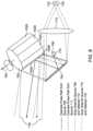
- FIG. 7depicts an embodiment of a signal steering system (e.g., signal steering system 404 of FIG. 4 ) according to some embodiments of the present technology.
- Polygon 702has ten reflective sides (sides 702 A- 702 E are visible in FIG. 7 ) but can have any number of reflective sides. For example, other examples of polygon 702 has 6, 8, or 20 sides).
- Polygon 702rotates about axis 703 based on a drive motor (not shown) to scan signals delivered from a light source (e.g., via output 706 , which is connected to a light source such as light source 402 described above) along a direction perpendicular or at a non-zero angle to axis of rotation 703 .
- a light sourcee.g., via output 706 , which is connected to a light source such as light source 402 described above
- Mirror galvanometer 704is positioned next to polygon 702 so that one or more signals emitted from light source output 706 (e.g., a fiber tip) reflect off of mirror galvanometer 704 and onto rotating polygon 702 .
- Mirror galvanometer 704tilts so as to scan one or more signals from output 706 to a direction different than the direction that polygon 702 scans signals (e.g., edges 704 A and 704 B tilt towards and away from polygon 702 about axis so as to scan pulses along a path that is parallel or at an angle to the axis of rotation of polygon 702 ).
- polygon 702is responsible for scanning one or more signals in the horizontal direction of the LiDAR system and mirror galvanometer 704 is responsible for scanning one or more signals in the vertical direction.
- polygon 702 and mirror galvanometer 704are configured in the reverse manner. While the example in FIG. 7 uses a mirror galvanometer, other components can be used in its place. For example, one or more rotating mirrors or a grating (with different wavelength pulses) may be used.
- the solid black linerepresents one example signal path through the signal steering system.
- lens 710is depicted as a single lens, in some variations it is a system of one or more optics.
- FIG. 8depicts a similar system as depicted in FIG. 7 except a second light source is added that provides one or more signals from output 714 .
- the light source for output 714may be the same or different than the light source for output 706 , and the light transmitted by output 714 may have the same or a different wavelength as the light transmitted by output 706 .
- Using multiple light outputscan increase the points density of a points map without sacrificing the maximum unambiguous detection range of the system.
- light output 714can be positioned to transmit light at a different angle from output 706 . Because of the different angles, light transmitted from light source 706 is directed to an area different from light transmitted from output 714 .
- the dotted lineshows one example pulse path for pulses emitted from output 714 .
- the region 716(the dashed/double-dotted line) indicates the region from which return signals from scattered signals returns to the LiDAR system.
- the returned lightis reflected off polygon 702 and mirror galvanometer 704 and focused on detectors 712 and 718 by lens 710 .
- Detectors 712 and 718can each be configured to receive returned light from one of the outputs 706 and 714 , and such configuration can be achieved by precisely controlling the position of the detectors 712 and 718 as well as the wavelength(s) of the transmitted light. Note that the same lens (or optic system) can be used for both detector 712 and 718 .
- the offset between outputs 706 and 714means that the light returned to the LiDAR system will have a similar offset.
- detectors 712 and 718based on the relative positioning of their respective light source outputs (e.g., respective positions of outputs 706 and 714 ) and, optionally, by properly controlling the wavelength(s) of the transmitted light, the returned light will be properly focused on to the correct detectors, and each received light can be a point in the points map. Therefore, compare to the system with only one output 706 , the system with two outputs can maintain the same pulse repetition rate and produce twice the number of points or reduce the pulse repetition rate by half and still produce the same number of points.
- a system with two light outputscan reduce the pulse repetition rate from 1 MHz to 500 KHz, thereby increasing its maximum unambiguous detection range from 150 meters to 300 meters, without sacrificing points density of the resulting points map.
- a pulse repetition rate of between 200 and 2 MHzis contemplated and disclosed.
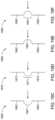
- FIG. 9depicts a point map from a first design.
- This designhas two channels (e.g., two light source outputs and two light detectors) placed in a way that the exiting beams have an angle of 8 degrees vertically.
- the scanned patternhas vertical overlap.
- the scanned rangeis + ⁇ 56 degrees horizontally and +12 ⁇ 20 degrees vertically.
- FIG. 10depicts a point map from a second design.
- This designhas two channels (e.g., two light source outputs and two light detectors) placed in a way that the exiting beams have an angle of 6 degrees.
- the scanned patternhas horizontal overlap (+ ⁇ 45 degrees).
- the scanned rangeis + ⁇ 67 degrees horizontally and +12 ⁇ 20 degrees vertically.
- Exiting beams of two channelsare not necessary to separate with a certain angle (e.g. 6 degree in FIG. 10 ) to obtain a larger horizontal range.
- Horizontal displacement of existing beamscan be used to expand the horizontal range.
- two exit beamsmay be pointed that same angle, but are offset with respect to each other in the same plane. Due to these different positions, each channel is reflected by different part of polygon and therefore covers a different horizontal range. By combining the two channels, the total horizontal range is increased.
- FIG. 11depicts a point map from a third design.
- This designhas three channels (e.g., three light source outputs and three light detectors) to increase point density. About 2.88 million points per second can be obtained by using 3 fiber tips and 3 detectors. The resolution can be further reduced to 0.07 degrees for both directions. The speed of the polygon can be reduced to 6000 rpm.
- FIG. 12shows illustrative field of view (FOV) 1200 of a LiDAR system according to an embodiment.
- FOV 1200is a two-dimensional space bounded by X and Y dimensions.
- ROIregions of interest
- FIG. 12shows five different illustrative ROIs 1210 - 1214 to illustrate different regions within FOV 1200 that require additional data points than other regions within FOV 1200 .
- ROI 1210occupies an entire band of a fixed y-axis height across the x-axis of FOV 1200 .
- ROIs 1211 and 1212show localized ROIs below ROI 1210
- ROIs 1213 and 1214show localized ROIs above ROI 1210 .
- any number of ROIsmay exist and that the ROIs can occupy any portion of FOV 1200 .
- Embodiments discussed hereinenable additional data points to be collected in the ROIs in a manner that does not disrupt the operation of the LiDAR system. That is, a LiDAR scanning system may scan the entirety of FOV 1200 each scan cycle, while controlling one or more parameters to obtain additional data points from (or increase resolution) of the ROIs 1211 - 1214 .
- FIG. 13shows an illustrative block diagram of LiDAR system 1300 according to an embodiment.
- LiDAR system 1300can include laser subsystem 1310 , receiver system 1320 , laser controller 1330 , region of interest controller 1340 , polygon structure 1350 , polygon controller 1355 , mirror 1360 , and mirror controller 1365 .
- LiDAR system 1300may be contained within one or more housings. In multiple housing embodiments, at least one of the housings may be a temperature controlled environment in which selection portions of LiDAR system 1300 (e.g., laser controller 1330 , laser source 1312 , controller 1340 ) are contained therein.
- Laser subsystem 1310may be operative to direct light energy towards mirror 1360 , which redirects the light energy to polygon structure 1350 .
- Mirror 1360also operative to redirect light energy received from polygon structure 1350 to receiver system 1320 .
- Mirror 1360may be moved under the control of mirror controller 1365 , which can control the speed and direction of mirror movement. As mirror 1360 moves, it causes light being transmitted by laser subsystem 1310 to interface with different portions of polygon structure 1350 .
- Polygon structure 1350is moving under the control of polygon controller 1355 and is operative to direct the light energy received from mirror 1360 in accordance with the field of view parameters of LiDAR system 1300 .
- LiDAR system 1300has a field of view with range of z, a lateral angle of x, and vertical angle of y
- the range zcan be controlled by the power of laser source 1312
- the vertical angle ycan be controlled by the movement of mirror 1360
- the lateral angle xcan be controlled by polygon structure 1350 .
- the vertical anglecan controlled by the polygon structure 1350 and that the lateral angle can be controlled by mirror 1360 .
- a frame ratemay refer to the time it takes for scanning system 1302 to complete one full scan of the FOV.
- scanning system 1302can obtain data points from each row (or column) of a plurality of rows (or columns) that are defined by the FOV.
- Each rowmay correspond to a vertical angle within the vertical range of the FOV.
- the vertical anglecan be controlled by mirror 1360 . As mirror 1360 moves, the vertical angle changes, thereby enabling scanning system 1302 to obtain data points from multiple rows within the FOV.
- Vertical angle resolutionrefers spacing between adjacent rows of data points. An increase in vertical angular resolution corresponds to denser spacing between adjacent rows, and such an increase can be achieved by decreasing the delta of the vertical angles between adjacent vertical angles.
- the delta between adjacent vertical angelscan be decreased by slowing down the movement of mirror 1360 . That is, as mirror movement speed slows down, the change in the vertical angle delta decreases.
- a decrease in vertical angular resolutioncorresponds to sparser spacing between adjacent rows, and such a decrease can be achieved by increasing the vertical angle delta.
- the delta between adjacent vertical angelscan be increased by speeding up the movement of mirror 1360 . That is, as mirror movement speeds up, the change in the vertical angle delta increases.
- the plurality of data points obtained within any rowmay depend on a horizontal angle within the horizontal range of the FOV.
- the horizontal rangemay be controlled by polygon 1350 , and the horizontal angle resolution may be controlled by a time interval of successive laser pulses.
- the time intervalis sometimes related to the repetition rate. A smaller time interval can result in increased horizontal angular resolution, and a larger time interval can result in decreased horizontal angular resolution.
- mirror 1360controls the vertical angle. It should be understood that mirror 1360 can be repurposed to control the horizontal angle and used in a system different than that shown in FIG. 13 .
- Laser subsystem 1310can include laser source 1312 and fiber tips 1314 - 1316 . Any number of fiber tips may be used as indicated the “n” designation of fiber tip 1316 . As shown, each of fiber tips 1314 - 1316 may be associated with laser source 1312 .
- Laser source 1312may be a fiber laser or diode laser.
- Fiber tips 1314 - 1316may be aligned in a fixed orientation so that the light exiting each tip strikes mirror 1360 at a particular location. The actual orientation may depend on several factors, including, for example, frame rate, mirror movement and speed, polygon speed, ROIs, repetition rate, etc. Additional discussion of fiber tips and their characteristics in obtaining additional data points within ROIs is discussed in more detail below.
- Receiver system 1320can include various components such as optics, detectors, control circuitry, and other circuitry.
- the opticsmay contain light-transmitting optics that gather laser light returned from mirror 1360 .
- Detectorsmay generate current or voltage signals when exposed to light energy through the optics.
- the detectorsmay be, for example, avalanche photo diodes.
- the outputs of the detectorscan be processed by the control circuitry and delivered to a control system (not shown) to enable processing of return pulses.
- Laser controller 1330may be operative to control laser source 1312 .
- laser controller 1330can control power of laser source 1312 , can control a repetition rate or time interval of light pulses emitted by laser source 1312 (via time interval adjustment module 1332 ), and can control pulse duration of laser source 1312 .
- Time interval adjustment module 1332may be operative to control and/or adjust the repetition rate/time interval of the transmitter pulse of laser 1310 .
- Time interval adjustment circuitry 1332can vary the repetition rate/time interval for different regions within the FOV. For example, the repetition rate may be increased for ROIs but may be decreased for areas of FOV that are not of interest. As another example, the time interval can be decreased for ROIs and increased for areas of FOV that are not of interest.
- Region of Interest controller 1340may be operative to control LiDAR system 1300 to obtain additional data points for the ROIs. That is, when LiDAR system 1300 is scanning a ROI, ROI controller 1340 may cause system 1300 to operate differently than when system 1300 is not scanning a ROI. ROI controller 1340 may control operation of laser controller 1330 , polygon controller 1355 , and mirror controller 1365 to alter the quantity of data being obtained by system 1300 . ROI controller 1340 may receive several inputs that dictate how it should control the scanning subsystem 1302 . The inputs can include, for example, frame rate 1342 , sparse regions 1343 , dense regions 1344 , distance range, or any other suitable input. Frame rate 1342 may specify the frequency at which scanning subsystem 1302 completes a FOV scan.
- Sparse and dense regions 1343 and 1344may provide specific locations of ROIs.
- dense regions 1344may correspond to ROIs and sparse regions 1343 may correspond to regions within the FOV that are not ROIs.
- Fiber tip angles 1345may be used as a design constraint within which scanning sub-system 1302 operates in order to optimally perform scanning.
- Polygon structure 1350may be constructed from a metal such as aluminum, plastic, or other material that can have a polished or mirrored surface. Polygon structure 1350 may be selectively masked to control the lateral dispersion of light energy being projected in accordance with the field of view of scanning subsystem 1302 . Polygon structure 1350 can include a number of facets to accommodate a desired horizontal field of view (FOV). The facets can be parallel or non-parallel to its symmetric axis. Polygon structure 1350 is operative to spin about an axis in a first direction at a substantially constant speed. The shape of polygon structure 1350 can be trimmed (e.g., chop off the sharp corner or tip to reduce overall weight or required geometry envelope, chamfer the sharp edge to reduce air resistance) for better operational performance.
- trimmede.g., chop off the sharp corner or tip to reduce overall weight or required geometry envelope, chamfer the sharp edge to reduce air resistance
- Mirror 1360may be a single plane or multi-plane mirror that oscillates back and forth to redirect light energy emitted by laser source 1312 to polygon 1350 .
- the single plane mirrormay provide higher resolutions at the top and bottom portions of the vertical field of view than the middle portion, whereas the multi-plane mirror may provide higher resolution at a middle portion of the vertical field of view than the top and bottom portions.
- Mirror 1360may be a galvanometer. Varying the oscillation speed within an oscillation cycle can enable scanning subsystem 1302 to acquire sparse or dense data points within the FOV. For example, if dense data points are required (for a particular ROI), the movement speed may be reduced, and if sparse data points are required (for non-ROIs), the movement speed may be increased.
- FIG. 14shows illustrative fiber tip arrangement according to an embodiment.
- Four fiber tips 1401 - 1404are shown to be oriented with respect to each other such that the same angle ⁇ exist between adjacent fiber tips.
- Multiple fiber tipsmay be used so that high data collection is achieved.
- the mirror movement speedis adjusted to a ROI speed (e.g., a speed that is slower than a sparse or non-ROI speed), the combination of additional fiber tips and reduced relative mirror movement speed yields denser data capture.
- a ROI speede.g., a speed that is slower than a sparse or non-ROI speed
- the mirror movement speedoperates at a non-ROI speed (e.g., a speed that is faster than the ROI speed)
- a non-ROI speede.g., a speed that is faster than the ROI speed
- the angle ⁇may be selected based on properties of the light energy being emitted by each fiber tip (e.g., size), speed and movement characteristics of a mirror (e.g., mirror 1360 ) for both ROIs and non-ROIs, and speed of the polygon (e.g., polygon structure 1350 ).
- the angles between each of tipsmay be the same or they can be different.
- all four fiber tipsmay be associated with the same laser source. Thus, if the laser source is turned OFF, none of the fiber tips will emit light energy.
- each fiber tipmay be associated with its own respective laser source. This embodiment provides a high degree of ON/OFF control of each fiber tip.
- a subset of the fiber tipsmay be associated with the same laser source. For example, fiber tips FT 1 and FT 3 may share a first common laser source, and fiber tips FT 2 and FT 4 may share a second common laser source. This embodiment provides a balance between all or none and individual ON/OFF control.
- FIG. 15 Ashows a multiple mirror alignment arrangement (MMAA) 1500 that may be used for ROI and non-ROI embodiments.
- MMAA 1500is an alternative to using multiple fiber tips such as that shown in FIG. 14 .
- MMAA 1500shows collimator 1510 , partial reflective mirrors 1521 - 1523 , and reflective mirror 1524 .
- Light energy originating from a laser source(not shown) is routed to collimator 1510 , which directs light energy to partial reflective mirror 1521 .
- Partial reflective mirror 1521permits a portion of the light energy to pass through (shown as exit path 1531 ) and the remaining light energy is redirected to partial reflective mirror 1522 .
- Partial reflective mirror 1522allows a portion of the light energy to pass through to partial reflective mirror 1523 .
- Partial reflective mirror 1522redirects light energy along exit path 1532 . Partial reflective mirror allows a portion of the light energy to pass through to partial reflective mirror 1524 . Partial reflective mirror 1523 redirects light energy along exit path 1533 . Reflective mirror 1524 may redirect all or at least a portion of all the remaining light energy along exit path 1534 .
- angles between adjacent exit pathsmay be selected to achieve the desired resolution for ROIs and non-ROIs.
- angles between adjacent exit pathsmay be similar to the ⁇ angles shown in FIG. 14 .
- the angle between adjacent exit pathsmay be fixed.
- the angle between adjacent exit pathsmay be variable. Variable angle adjustment may be used to provide different resolutions on demand. For example, if the LiDAR system is being used in a vehicle, the angles may be set to a first configuration when the vehicle operating in a first mode (e.g., driving at highway speeds or vehicle is driven by a first driver) and may be set to a second configuration when the vehicle is operating in a second mode (e.g., driving at city speeds or vehicle is driven by a second driver).
- a first modee.g., driving at highway speeds or vehicle is driven by a first driver
- a second modee.g., driving at city speeds or vehicle is driven by a second driver
- FIG. 15 Bshows another multiple mirror alignment arrangement (MMAA) 1501 that may be used for ROI and non-ROI embodiments.
- MMAA 1501is an alternative to MMAA 1500 .
- MMAA 1501shows collimator 1512 , partial reflective mirrors 1525 - 1527 , reflective mirror 1528 , and exit paths 1535 - 1538 .
- MMAA 1501is similar to MMAA 1500 with exception of the positioning of collimator 1512 .
- collimator 1512is positioned above mirror 1525 . If desired, collimator 1512 can be positioned below mirror 1528 .
- collimator 1512can be aimed at a different mirror such as mirror 1526 or mirror 1527 , and such mirrors can redirect the light energy as necessary to achieve the desired results.
- FIG. 15 Cshows an illustrative multiple collimator arrangement 1550 that may be used for ROI and non-ROI embodiments.
- Arrangement 1550can include collimators 1561 - 1563 .
- Each of collimators 1561 - 1563may be associated with its own laser source. Associating each collimator with its own laser source enables selective turning ON and OFF of light energy emanating from each collimator. For sparse regions, one or more of the laser sources may be turned OFF (to save power) and for dense regions, all laser sources may be turned ON to maximize resolution.
- Each of collimators 1561 - 1563may be fixed in a particular orientation to achieve the desired a angle between each collimator. If desired, each of collimators 1561 - 1563 may be movable to dynamically adjust the a angle between each collimator.
- FIG. 15 Dshows an illustrative collimator and lens arrangement 1570 that may be used to control divergence of the light beam existing collimator 1571 according to an embodiment.
- Lens 1572may be moved towards and away from collimator 1571 to adjust divergence of the light beam.
- Arrangement 1570may be used to adjust the size of the light beam as it is projected by the scanning system.
- ROI regionsit may be desirable to have a relatively narrow beam.
- lens 1572may positioned at a narrow beam distance away from the collimator 1571 .
- non-ROI regionsit may be desirable to have a relatively wide beam.
- lens 1572may positioned at a wide beam distance away from the collimator 1571 .
- FIG. 16shows illustrative scanning resolution using multiple fiber tips, a multiple mirror alignment arrangement, or multiple collimator arrangement according to an embodiment.
- the illustrative vertical resolution lines from fiber tips(FT 1 -FT 4 ) are shown.
- the resolution linesare grouped according to sparse resolution and dense resolution as shown. In sparse regions, the scanning system is moving the mirror at a relatively faster speed than when in the dense region, and in dense regions, the scanning system is moving the mirror at a relatively slower speed than when in the sparse region.
- the spacing between the adjacent scanning linesis substantially equidistant.
- each fiber tipmay provide multiple lines of resolution. For example, as shown, FT 1 provides four lines of resolution before FT 2 provides its four lines of resolution. Thus, each fiber tip provides four lines of resolution before transitioning to the next fiber tip. It should be understood that the number of lines of resolution provided by each fiber tip depends on a number of factors, including, for example, mirror speed, polygon speed, and angle between fiber tips.
- the lines of resolution among fiber tipsmay interlace at the transition between the sparse and dense regions. For example, at least one line of resolution from one or more of fiber tips FT 2 -FT 4 may be interlaced among the four lines of resolution pertaining to FT 1 (as shown in FIG. 17 A ).
- the angle between the fiber tipsmay be selected based on the mirror speeds, polygon speed, desired angular resolution of the ROI, and a requirement for the spacing between the resolution lines in the sparse region(s) to be substantially equidistant to each other. At least two different mirror speeds are used to provide the dense and sparse resolutions, and it is the variance in mirror speeds that can cause the resolution lines to be non-equidistant if the angles between fiber tips are not properly aligned. For example, assume that the angle of the dense region is ⁇ . ⁇ can represent the total degrees within the FOV that are part of the ROI and require dense resolution.
- the angle between fiber tips, ⁇can be approximately ⁇ /n, where n is the number of fiber tips.
- This ⁇ csreferred to as angle with constant speed may represent a target angle for the fiber tips, but additional calculations are required to take into account that the mirror operates at different speeds, and as a result ⁇ , cannot be set to exactly ⁇ /n.
- the sparse regionsmust be taken into account. In the sparse region, assume that the desired angle between adjacent lines of resolution is ⁇ . For the example, ⁇ may exist between FT 1 and FT 2 , between FT 2 and FT 3 , between FT 3 and FT 4 , between FT 4 and FT 1 in the sparse region.
- the variables of ⁇ , n, mirror speed, and polygon speedare selected such that ⁇ vs is the same as or approximately the same as ⁇ cs . Selecting the variables such that ⁇ vs is the same as or approximately the same as ⁇ cs , enables the scanning system to achieve the desired scanning densities for both ROI and non-ROI regions within the FOV each frame.
- FIG. 17 Ashows another illustrative diagram of vertical resolution using multiple fiber tips or a multiple mirror alignment arrangement, according to an embodiment.
- Sparse regions and a dense regionare shown.
- Four fiber tips FT 1 - 4are used.
- the resolution lines for each fiber tipare evenly spaced.
- the vertical lines of resolutionare substantially more dense than the vertical lines of resolution in the sparse regions.
- the vertical lines of resolutionare grouped predominantly for each fiber tip, however, interlacing resolution lines from other fiber tips may exist within a particular group.
- FIG. 17 Bshows an illustrative close-up view of a sparse region within FIG. 17 A
- FIG. 17 Cshows an illustrative close-up view of the dense region within FIG. 17 A , according to various embodiments. Note that the scaling factor in FIG. 17 B is less zoomed in than it is in FIG. 17 C . As a result, FIG. 17 B shows lines of resolution for multiple fiber tips, and where FIG. 17 C shows multiple lines of resolution for only one fiber tip.
- the laser subsysteme.g., the fiber tips, multiple mirror alignment arrangement, or multiple collimator arrangement
- the laser subsystemcan be oriented in a horizontal direction (as opposed to the above-described vertical direction) to provide dynamic horizontal resolution.
- the repetition rate or time intervalcan be changed to dynamically control the horizontal resolution.
- Thisprovides dual axis dynamic resolution control that can be synchronized by a controller (e.g., ROI controller 1340 ) to provide increased resolution for ROIs and decreased resolution for non-ROIs for both vertical and horizontal orientations.
- a controllere.g., ROI controller 1340
- the mirror movement speedis decreased and the time interval between successive light pulses is decreased (thereby increasing repetition rate).
- the scan cyclecomes across a non-ROI
- the mirror movement speedis increased and the time interval between successive light pulses is increased (thereby decreasing repetition rate).
- the laser source(s)can be selectively turned ON and OFF to provide vertical dynamic range (assuming the laser subsystem is oriented as such). This can eliminate the need to adjust the mirror speed to achieve dynamic vertical resolution. If desired, however, the laser source(s) can be selectively turned ON and OFF in conjunction with variations in mirror movement speed.
- FIG. 18shows illustrative FOV 1800 with variable sized laser pulses according to an embodiment.
- FOV 1800includes two sparse regions and one dense region as shown. Both the sparse and dense regions show illustrative light pulses that take the form of different sized circles. The sparse sized circles are larger than the dense sized circles.
- the mirror speedmay be moving at a sparse speed and the repetition rate may be set to a sparse region repetition rate.
- the mirror speedmay be moving at the dense speed and the repetition rate may be set to a dense region repetition rate.
- the sparse speedis faster than the dense speed and the sparse region repetition rate is slower than the dense region repetition rate.
- the circle size of the light pulses projected into the sparse regionwere the same size as the circles in the dense region, underfilling could exist. Underfill may occur when too much space exists between adjacent light pulse circles. Thus, in order to minimize underfill, it is desirable to project an appropriately sized light pulse for both the sparse and dense regions.
- FIG. 19 Ashows an illustrative mirror mirror 1900 arranged to include curved mirror portion 1902 , planar portion 1904 , and curved mirror portion 1906 .
- Planar portion 1904is positioned between curved mirror portions 1902 and 1906 .
- Curved mirror portions 1902 and 1906generate a convergence of light pulses to create a relatively larger sized circle (for the sparse regions).
- Planar portion 1904may not alter the size of the light pulse interacting with it, and used projecting light into the dense region.
- FIG. 19 Bshows another illustrative mirror 1950 according to an embodiment.
- Mirror 1950may include a curved mirror portions 1952 and 1956 and planar portion 1954 .
- planar portion 1954may be a prism (e.g., similar to that shown in the mirror of FIG. 21 ).
- FIG. 19 Cshows another illustrative mirror 1960 that incorporates a concave continuously curved portion 1961 between two planar portions 1962 and 1963 according to an embodiment.
- the laser beam(s)is/are directed to portion 1961 and any return pulses can be reflected by planar portions 1962 and 1963 .
- FIG. 19 Dshows yet another illustrative mirror 1970 that incorporates a concave step-wise curved portion 1971 between two planar portions 1972 and 1973 according to an embodiment.
- the laser beam(s)is/are directed to portion 1971 and any return pulses can be reflected by planar portions 1972 and 1973 .
- FIG. 19 Eshows yet another illustrative mirror 1980 that incorporates a convex continuously curved portion 1981 between two planar portions 1982 and 1983 according to an embodiment.
- FIG. 19 Fshows another illustrative mirror 1990 that incorporates a convex step-wise curved portion 1961 between two planar portions 1962 and 1963 according to an embodiment.
- the laser beam(s)is/are directed to portion 1991 and any return pulses can be reflected by planar portions 1992 and 1993 .
- FIG. 19 Gshows another illustrative mirror 1965 that incorporates a concave portion 1966 between two planar portions 1967 and 1968 according to an embodiment.
- Concave portion 1966has a flat portion positioned between two curved portions. The curved portions are convex with respect to the incoming laser beam. The laser beam(s) is/are directed to portion 1966 and any return pulses can be reflected by planar portions 1967 and 1968 .
- FIG. 19 Hshows yet another illustrative mirror 1975 that incorporates a concave curved portion 1976 between two planar portions 1977 and 1978 according to an embodiment.
- Concave portion 1976has a flat portion positioned between two curved portions. The curved portions are concave with respect to the incoming laser beam.
- FIG. 19 Ishows yet another illustrative mirror 1985 that incorporates a convex portion 1986 between two planar portions 1987 and 1988 according to an embodiment.
- Convex portion 1986has a flat portion positioned between two curved portions. The curved portions are convex with respect to the incoming laser beam.
- the laser beam(s)is/are directed to portion 1986 and any return pulses can be reflected by planar portions 1987 and 1988 .
- FIG. 19 Jshows another illustrative mirror 1995 that incorporates a convex portion 1996 between two planar portions 1997 and 1998 according to an embodiment.
- Convex portion 1996has a flat portion positioned between two curved portions. The curved portions are concave with respect to the incoming laser beam.
- the laser beam(s)is/are directed to portion 1996 and any return pulses can be reflected by planar portions 1997 and 1998 .
- FIG. 20depicts a similar system as depicted in FIG. 8 except mirror 704 includes prism 2020 and light sources 706 and 708 are moved out of the scan areas for detectors 708 and 712 . Placing light sources 706 and 708 out of the return paths for detectors 708 and 712 reduces or eliminates any interference that may occur. It should be understood that the size of prism 2020 is shown in an exaggerated size for illustrative purposes, and that the size of prism is preferably minimized to lessen its impact on the return paths.
- FIG. 21depicts a similar system as that shown in FIG. 20 , except that mirror 704 is replaced with a curved mirror 2104 (e.g., similar to curved mirror 1950 ).
- Curved mirror 2104can include planar portion 2105 , which may be a prism, and curved mirror portions 2106 and 2107 .
- Use of curved mirror 2104can perform double duty of generating different sized laser pulses (as discussed above in connection with FIG. 18 ) and as a focusing lens 710 . As such, lens 710 can be eliminated in the embodiment shown in FIG. 21 .
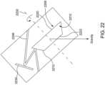
- FIGS. 9 - 11 discussed aboveeach show a curve in the data points being acquired in their respective fields of view.
- the curvecan be flattened by using a polygon that has a trapezoidal cross-section such as that shown in FIG. 22 .
- FIG. 22shows an illustrative polygon 2200 that rotates around rotation axis 2202 . Note that the sequence of light travel is different for FIG. 22 than it is for FIG. 13 , in that the source light strikes polygon 2200 before interacting with mirror 2230 . It should be appreciated that the light source can strike mirror 2230 before interacting with polygon 2200 .
- FIG. 22also shows illustrative mirror 2230 and exemplary light path 2246 .
- Polygon 2200may have a trapezoidal cross-section in which facet 2210 is not parallel to facet 2212 , but top and bottom surfaces 2220 and 2222 can be parallel to each other.
- Rotation axis 2202is not in line with gravity (the gravity axis is shown pointing straight down). That is, if rotation axis 2202 were in line with gravity, it would be parallel with the gravity line.
- Rotation axis 2202can be line with gravity, if desired.
- Rotation axis 2202may be angled with respect to gravity so that light energy being reflected off of polygon 2200 is pointed in a useful direction (e.g., towards the road as opposed to the sky).
- FIG. 23depicts a point map using polygon 2200 of FIG. 22 .
- the point mapincludes two channels (e.g., two light source outputs and two light detectors).
- the scanned patternhas vertical overlap and no curve in the vertical direction.
- FIG. 24shows an illustrative block diagram of LiDAR system 2400 according to an embodiment.
- LiDAR system 2400is similar to system 1300 of FIG. 24 , but includes additional components to extend the field of view. Whereas system 1300 may provide 120 degrees of horizontal view, system 2400 may provide 360 degrees of horizontal view.
- System 2400can include first subsystem 2410 , second subsystem 2420 , third subsystem 2430 , polygon 2440 , polygon control 2444 , and ROI controller 2450 . Each of first, second, and third subsystems 2410 , 2420 , and 2430 may share polygon 2440 and be controlled by the same ROI controller 2450 .
- each of subsystems 2410 , 2420 , and 2430may be independently controlled by their own respective ROI controller.
- ROI controllermay be similar to ROI controller 1340 of FIG. 13 .
- Each of systems 2410 , 2420 , and 2430can include a laser controller (e.g., similar to laser controller 1330 ), a laser subsystem (e.g., similar to laser subsystem 1310 ), a receiver system (not shown), a mirror (e.g., similar to mirror 1360 ), and mirror controller (e.g., similar to mirror controller 1365 ).
- LiDAR system 2400may be contained within one or more housings. Any of the embodiments (e.g., FIGS. 1 - 23 ) discussed herein may be used in system 2400 .
- each of subsystems 2410 , 2420 , and 2430can be responsible for observing a different portion (e.g., a particular 120 degree portion) of a 360 degree field of view.
- the observed portions for each subsystemmay or may not overlap.
- Each subsystemcan be independently controlled to focus on ROI(s) in their respective FOVs.
- four subsystemsmay be used (as opposed to three subsystems), each of the four subsystem may be responsible for observing a 90 degree portion of the 360 degree field of view.
- the observed portions for all four subsystemsmay or may not overlap.
- five of more subsystemsmay be used.
- the LiDAR systemcan control the vertical and horizontal angular resolution of the light beams being projected by the scanning system.
- the angular resolutiondetermines how many points can be observed from an object at a certain distance.
- the vertical angular resolutionis defined by the vertical angle between adjacent light beam projections. As the vertical angle decreases, the separation between adjacent light beams is decreased, thereby resulting in more data points (or increased angular resolution). As the angle between adjacent light beams increases, the separation between adjacent light beams is increased, thereby resulting in fewer data points (or decreased angular resolution). It may be desirable to acquire more data points for objects that are relatively far away than for objects that are relatively close. See, for example, FIG.
- FIG. 25 Awhich shows close object 2505 and far object 2510 and the illustrative data points captured from both objects.
- the vertical angular resolution in FIG. 25 Ais constant across the entire vertical FOV.
- Close object data points 2507correspond to data points obtained from close object 2505
- far object data points 2512correspond to data points obtained from far object 2510 .
- the data points collected for far object 2510are relatively sparse compared to data points collected for close object 2505 .
- FIG. 25 Bshows an illustrative scenario where the angular resolution is variable across the vertical FOV.
- the vertical angle deltais ⁇ and for region 2570 , the vertical angle delta is ⁇ , where ⁇ is less than ⁇ .
- Far object data points 2552correspond to far object 2550 .
- the number of data points collected from the far objectis greater when the angular resolution is increased such that density of light beams, and corresponding number of data points being collected, is increased.
- FIGS. 25 A and 25 Bshow angular resolution in the vertical FOV, angular resolution may also occur in the horizontal FOV.
- the total number of data points that can be obtainedare constrained by design constraints of the LiDAR system. Therefore, it is desirable to optimize the angular resolution for a given LiDAR system for one or more ROI(s).
- the LiDAR systemgenerally does not have a priori knowledge of the object(s) it is trying to detect, but certain assumptions can be made, and based on these assumptions, the angular resolution can be customized for different portions of the FOV. For example, the angular resolution may be customized for ROI(s) and/or assumption exceptions.
- the center FOVmay have the highest probability of containing a relevant object at distance. For example, in the vertical context, below the center FOV focuses on the ground, and above the center FOV focuses on the sky. Thus, the center vertical FOV is more desirable for improved angular resolution. In the horizontal FOV context, left and right focusing is generally irrelevant at large distances.
- FIG. 26 Ashows an illustrative optimized angular resolution in a vertical FOV with respect to the ground according to an embodiment.
- FIG. 26 Bshows an illustrative graph of angular vertical resolution as a function of the vertical angle in the FOV according to an embodiment.
- the angular vertical resolutionis variable between vertical angels of ⁇ 25 degrees and ⁇ 5 degrees, constant between vertical angles of ⁇ 5 and 3 degrees, and variable between vertical angles of 3 and 19 degrees.
- the variation in the angular resolution between ⁇ 25 and ⁇ 5 degreesis such that the ground distance between each adjacent light beam is substantially constant, as shown in FIG. 26 A .
- the constant distance in between adjacent light pulsesis possible by continuously varying the angular resolution.
- the angular resolutioncan be controlled by varying the movement speed of the mirror (e.g., mirror 1360 ).
- the delta angle between adjacent light pulsesincreases in proportion to its relative angle away from the zero vertical angle. For example, at ⁇ 25 degrees, The delta angle within the center region (e.g., shown as ⁇ 5 to 3 degrees) is constant and represents the smallest angle difference between adjacent light pulses throughout the entire vertical FOV.
- the angular resolution of the vertical angles above 3 degreesmay be continuously variable in same manner as the angular resolution for the vertical angles below ⁇ 5 degrees. It should be appreciated that the numbers used in FIG. 26 B are merely illustrative and that ranges for the variable angular values and the constant angular values may be different than that shown and described.
- FIG. 27shows an illustrative graph of step changing angular vertical resolution as a function of the vertical angle in the FOV according to an embodiment. Both step change vertical resolution line 2710 and continuous vertical resolution line 2720 are shown for comparison purposes. Step change vertical resolution line 2710 shows that the vertical resolution remains fixed for a fixed range of vertical angles in FOV before changing to a different vertical resolution. Step change vertical resolution line 2710 may be easier to implement than continuous vertical resolution line 2720 .
- variable and constant angular resolutionmay be performed using the embodiments described above in connection with FIGS. 1 - 24 or any other system capable of adjusting the angular resolution.
- the mirror speedcan be variably adjusted to yield angular resolution angles of FIGS. 26 B and 27 .
- FIG. 28shows illustrative process 2800 for handing ROIs according to an embodiment.
- Process 2800may be implemented in a system such as system 1300 as discussed above.
- at least one range of interest (ROI) regioncan be received within the LiDAR scanning system field of view (FOV), wherein any portion within the FOV not within the at least one ROI region is a non-ROI region or a region of non-interest.
- a controllersuch as ROI controller 1340 may receive an indication of the ROIs.
- dense regions and sparse regions within the FOVmay be provided or programmed to the ROI controller to specify ROIs and non-ROIs.
- the LiDAR scanning systemdirects light pulses to the FOV in a controlled manner by scanning across each horizontal row according the horizontal boundary of the FOV for multiple rows that comprise the vertical boundary of the FOV.
- the LiDAR scanning systemWhen the LiDAR scanning system is aimed at a non-ROI region, the LiDAR scanning system can be operated at a first vertical scanning rate and at a first laser pulse interval (as indicated by step 2820 ). When the LiDAR scanning system is aimed at a ROI region, the scanning system can operate at a second vertical scanning rate and at a second a second laser pulse interval (as indicated by step 2830 ). The second laser pulse interval can be slower than the first laser pulse interval.
- FIG. 29shows illustrative process 2900 for handing ROIs according to an embodiment.
- a plurality of light beamscan be emitted towards a scanning system that controls where the plurality of light beams are directed within a field of view (FOV). For example, two or more light beams may be directed to the FOV. Each of the plurality of light beams are aligned at a fixed angle with respect to each other.
- the scanning systemis aimed at a region of interest (ROI) within the FOV
- the plurality of light beamscan yield a dense resolution.
- the dense regionis shown in FIG. 16 and FIG. 17 A .
- the plurality of light beamscan yield a sparse resolution (as illustrated in FIGS. 16 and 17 A ).
- FIG. 30shows illustrative process 3000 for handing ROIs according to an embodiment.
- the LiDAR systemcan be used to scan a field of view (FOV).
- the LiDAR systemcontrols aim of at least one light beam as it scans the FOV, and the FOV can be bounded by a first directional degree range (e.g., vertical angles) and a second directional degree range (e.g., horizontal angles).
- a range of interest (ROI)is defined within the FOV that occupies a first portion of the first directional degree range.
- ROIrange of interest
- an angular resolution of the at least one light beamcan be adjusted while the LiDAR system scans the FOV, wherein when the at least one light beam is aimed at the ROI, the angular resolution is constant throughout the first portion of the first directional degree range, and wherein the wherein when the at least one light beam is aimed at a region of non-interest (RONI), the angular resolution is varied across the first directional degree range encompassing the RONI.
- RONIregion of non-interest
- any processes described with respect to FIGS. 1 - 30may each be implemented by software, but may also be implemented in hardware, firmware, or any combination of software, hardware, and firmware. They each may also be embodied as machine- or computer-readable code recorded on a machine- or computer-readable medium.
- the computer-readable mediummay be any data storage device that can store data or instructions which can thereafter be read by a computer system. Examples of the computer-readable medium may include, but are not limited to, read-only memory, random-access memory, flash memory, CD-ROMs, DVDs, magnetic tape, and optical data storage devices.
- the computer-readable mediumcan also be distributed over network-coupled computer systems so that the computer readable code is stored and executed in a distributed fashion.
- the computer-readable mediummay be communicated from one electronic subsystem or device to another electronic subsystem or device using any suitable communications protocol.
- the computer-readable mediummay embody computer-readable code, instructions, data structures, program modules, or other data in a modulated data signal, such as a carrier wave or other transport mechanism, and may include any information delivery media.
- a modulated data signalmay be a signal that has one or more of its characteristics set or changed in such a manner as to encode information in the signal.
- any or each module or state machine discussed hereinmay be provided as a software construct, firmware construct, one or more hardware components, or a combination thereof.
- any one or more of the state machines or modulesmay be described in the general context of computer-executable instructions, such as program modules, that may be executed by one or more computers or other devices.
- a program modulemay include one or more routines, programs, objects, components, and/or data structures that may perform one or more particular tasks or that may implement one or more particular abstract data types.
- modules or state machinesare merely illustrative, and that the number, configuration, functionality, and interconnection of existing modules may be modified or omitted, additional modules may be added, and the interconnection of certain modules may be altered.
Landscapes
- Physics & Mathematics (AREA)
- Engineering & Computer Science (AREA)
- General Physics & Mathematics (AREA)
- Computer Networks & Wireless Communication (AREA)
- Radar, Positioning & Navigation (AREA)
- Remote Sensing (AREA)
- Electromagnetism (AREA)
- Optics & Photonics (AREA)
- Optical Radar Systems And Details Thereof (AREA)
Abstract
Description
α=αvs=ϕ*n*2−ϕ
where αvsis the angle with a variable speed mirror, ϕ is the angle between adjacent lines of resolution within the sparse region, n is the number of fiber tips, and the
Claims (21)
Priority Applications (3)
| Application Number | Priority Date | Filing Date | Title |
|---|---|---|---|
| US16/439,230US11675053B2 (en) | 2018-06-15 | 2019-06-12 | LiDAR systems and methods for focusing on ranges of interest |
| US17/530,370US11860313B2 (en) | 2018-06-15 | 2021-11-18 | LiDAR systems and methods for focusing on ranges of interest |
| US18/223,490US12276759B2 (en) | 2018-06-15 | 2023-07-18 | LiDAR systems and methods for focusing on ranges of interest |
Applications Claiming Priority (2)
| Application Number | Priority Date | Filing Date | Title |
|---|---|---|---|
| US201862685333P | 2018-06-15 | 2018-06-15 | |
| US16/439,230US11675053B2 (en) | 2018-06-15 | 2019-06-12 | LiDAR systems and methods for focusing on ranges of interest |
Related Child Applications (1)
| Application Number | Title | Priority Date | Filing Date |
|---|---|---|---|
| US17/530,370ContinuationUS11860313B2 (en) | 2018-06-15 | 2021-11-18 | LiDAR systems and methods for focusing on ranges of interest |
Publications (2)
| Publication Number | Publication Date |
|---|---|
| US20190383911A1 US20190383911A1 (en) | 2019-12-19 |
| US11675053B2true US11675053B2 (en) | 2023-06-13 |
Family
ID=68839234
Family Applications (3)
| Application Number | Title | Priority Date | Filing Date |
|---|---|---|---|
| US16/439,230Active2042-01-14US11675053B2 (en) | 2018-06-15 | 2019-06-12 | LiDAR systems and methods for focusing on ranges of interest |
| US17/530,370ActiveUS11860313B2 (en) | 2018-06-15 | 2021-11-18 | LiDAR systems and methods for focusing on ranges of interest |
| US18/223,490ActiveUS12276759B2 (en) | 2018-06-15 | 2023-07-18 | LiDAR systems and methods for focusing on ranges of interest |
Family Applications After (2)
| Application Number | Title | Priority Date | Filing Date |
|---|---|---|---|
| US17/530,370ActiveUS11860313B2 (en) | 2018-06-15 | 2021-11-18 | LiDAR systems and methods for focusing on ranges of interest |
| US18/223,490ActiveUS12276759B2 (en) | 2018-06-15 | 2023-07-18 | LiDAR systems and methods for focusing on ranges of interest |
Country Status (3)
| Country | Link |
|---|---|
| US (3) | US11675053B2 (en) |
| CN (3) | CN112585492B (en) |
| WO (1) | WO2019241396A1 (en) |
Families Citing this family (30)
| Publication number | Priority date | Publication date | Assignee | Title |
|---|---|---|---|---|
| US10816666B2 (en)* | 2017-11-21 | 2020-10-27 | Magna Electronics Inc. | Vehicle sensing system with calibration/fusion of point cloud partitions |
| EP4090995A1 (en)* | 2020-03-06 | 2022-11-23 | Huawei Technologies Co., Ltd. | Light-based ranging device design and operation |
| CN113721220A (en)* | 2020-05-26 | 2021-11-30 | 北京光秒科技有限公司 | Method for realizing two-dimensional optical scanning by single-degree-of-freedom rotation |
| US11573299B2 (en)* | 2020-06-03 | 2023-02-07 | Seagate Technology Llc | LIDAR scan profile parameterization |
| GB2598078B (en)* | 2020-06-17 | 2022-12-21 | Jaguar Land Rover Ltd | Vehicle control system using a scanning system |
| US10942277B1 (en)* | 2020-06-19 | 2021-03-09 | Aurora Innovation, Inc. | LIDAR system |
| US20220065998A1 (en)* | 2020-09-03 | 2022-03-03 | Kabushiki Kaisha Toshiba | Distance measurement device |
| EP3982156A1 (en)* | 2020-10-09 | 2022-04-13 | Yandex Self Driving Group Llc | Lidar systems and methods with selective scanning |
| DE102020213668A1 (en)* | 2020-10-30 | 2022-05-05 | Volkswagen Aktiengesellschaft | Extended range lidar sensor system |
| EP4285143A4 (en)* | 2021-01-28 | 2024-11-27 | The Board Of Trustees Of The Leland Stanford Junior University | MULTIPLE FREQUENCY COMPONENT SCANNING, INVOLVING BALANCED OR OPTIMIZED SCAN PATTERN DESIGN AND ATTRIBUTES |
| US11555895B2 (en) | 2021-04-20 | 2023-01-17 | Innovusion, Inc. | Dynamic compensation to polygon and motor tolerance using galvo control profile |
| US11881028B2 (en)* | 2021-05-04 | 2024-01-23 | GM Global Technology Operations LLC | Vehicle lidar system with neural network-based dual density point cloud generator |
| WO2022246278A1 (en)* | 2021-05-21 | 2022-11-24 | Innovusion, Inc. | Movement profiles for smart scanning using galvonometer mirror inside lidar scanner |
| EP4314884A1 (en) | 2021-05-21 | 2024-02-07 | Innovusion, Inc. | Movement profiles for smart scanning using galvonometer mirror inside lidar scanner |
| US11402475B1 (en)* | 2021-05-28 | 2022-08-02 | Aeva, Inc. | Techniques for periodic synchronization of light system |
| CN115704904B (en)* | 2021-08-09 | 2023-09-15 | 北京一径科技有限公司 | Laser radar system |
| CN113703003B (en)* | 2021-08-09 | 2022-11-18 | 北京一径科技有限公司 | Laser scanning control method and device and storage medium |
| CN116224282A (en)* | 2021-12-03 | 2023-06-06 | 苏州一径科技有限公司 | Dynamic resolution control method, device, equipment and storage medium |
| US20230258806A1 (en)* | 2022-02-16 | 2023-08-17 | Beijing Voyager Technology Co., Ltd. | Lidar system for dynamically selecting field-of-views to scan with different resolutions |
| WO2023183599A1 (en)* | 2022-03-25 | 2023-09-28 | Innovusion, Inc. | Lidar system communication using data encoding for communicating point cloud data |
| CN118871806A (en)* | 2022-04-22 | 2024-10-29 | 华为技术有限公司 | A scanning method, a detection device and a terminal |
| CN115166803B (en)* | 2022-07-04 | 2024-10-18 | 中国人民解放军国防科技大学 | Multi-mode satellite and inertial combined real-time navigation method and equipment |
| CN115144839A (en)* | 2022-07-04 | 2022-10-04 | 杭州宇树科技有限公司 | A 3D LiDAR and its Footed Robot and Cleaning Robot |
| CN115856834A (en)* | 2022-07-26 | 2023-03-28 | 深圳市速腾聚创科技有限公司 | Point cloud encryption method and device, storage medium and laser radar |
| JP7556922B2 (en)* | 2022-09-02 | 2024-09-26 | 本田技研工業株式会社 | External Recognition Device |
| US20240230848A9 (en)* | 2022-10-21 | 2024-07-11 | Innovusion, Inc. | Two dimensional transmitter array-based lidar |
| CN120370291A (en)* | 2022-12-15 | 2025-07-25 | 深圳市速腾聚创科技有限公司 | Radar control method, radar control device, terminal equipment and computer readable storage medium |
| US20240241225A1 (en)* | 2023-01-18 | 2024-07-18 | Innoviz Technologies Ltd. | Eye safe lidar system with variable resolution multi-beam scanning |
| DE102023108684A1 (en) | 2023-04-05 | 2024-10-10 | Valeo Detection Systems GmbH | SENSOR SYSTEM AND METHOD FOR OPERATING A SENSOR SYSTEM |
| WO2025129446A1 (en)* | 2023-12-19 | 2025-06-26 | 深圳引望智能技术有限公司 | Scanning module, detection apparatus, laser radar, and terminal |
Citations (244)
| Publication number | Priority date | Publication date | Assignee | Title |
|---|---|---|---|---|
| US3897150A (en) | 1972-04-03 | 1975-07-29 | Hughes Aircraft Co | Scanned laser imaging and ranging system |
| GB1427164A (en) | 1972-02-19 | 1976-03-10 | Nippon Electric Co | Interference eliminating system for radars |
| GB2000411A (en) | 1977-06-15 | 1979-01-04 | Impulsphysik Gmbh | Ceilometric method and apparatus |
| US4412720A (en) | 1980-04-23 | 1983-11-01 | Cselt - Centro Studi E Laboratori Telecomunicazioni S.P.A. | Optical system coupling a rectangular light source to a circular light receiver |
| US4464048A (en) | 1981-03-25 | 1984-08-07 | Barr & Stroud Limited | Laser rangefinders |
| JPS628119A (en) | 1985-07-04 | 1987-01-16 | Matsushita Electric Ind Co Ltd | Polygon mirror |
| US4923263A (en) | 1988-09-22 | 1990-05-08 | The United States Of America As Represented By The Secretary Of The Army | Rotating mirror optical scanning device |
| US5006721A (en) | 1990-03-23 | 1991-04-09 | Perceptron, Inc. | Lidar scanning system |
| US5157451A (en) | 1991-04-01 | 1992-10-20 | John Taboada | Laser imaging and ranging system using two cameras |
| DE4142702A1 (en) | 1991-12-21 | 1993-06-24 | Leuze Electronic Gmbh & Co | Laser scanning equipment of three=dimensional objects - has output of laser directed by combination of rotating polygon mirror and oscillating plain mirror onto object |
| JPH0683998A (en) | 1992-08-31 | 1994-03-25 | Idec Izumi Corp | Bar-code reader |
| US5303084A (en) | 1991-08-27 | 1994-04-12 | Kaman Aerospace Corporation | Laser light beam homogenizer and imaging lidar system incorporating same |
| US5319434A (en) | 1992-12-30 | 1994-06-07 | Litton Systems, Inc. | Laser rangefinder apparatus with fiber optic interface |
| US5369661A (en) | 1991-02-07 | 1994-11-29 | Nippon Steel Corporation | Semiconductor laser-pumped solid state laser system and optical coupling system coupling semiconductor laser with optical fiber |
| US5442358A (en) | 1991-08-16 | 1995-08-15 | Kaman Aerospace Corporation | Imaging lidar transmitter downlink for command guidance of underwater vehicle |
| US5546188A (en) | 1992-11-23 | 1996-08-13 | Schwartz Electro-Optics, Inc. | Intelligent vehicle highway system sensor and method |
| US5579153A (en) | 1992-04-27 | 1996-11-26 | Pirelli Cavi S.P.A. | Optical power limiting amplifier |
| EP0757257A2 (en) | 1995-07-31 | 1997-02-05 | HE HOLDINGS, INC. dba HUGHES ELECTRONICS | Laser range finder receiver |
| US5657077A (en) | 1993-02-18 | 1997-08-12 | Deangelis; Douglas J. | Event recording system with digital line camera |
| WO1998016801A1 (en) | 1996-10-11 | 1998-04-23 | Schwartz Electro-Optics, Inc. | Intelligent vehicle highway multi-lane sensor |
| US5793491A (en) | 1992-12-30 | 1998-08-11 | Schwartz Electro-Optics, Inc. | Intelligent vehicle highway system multi-lane sensor and method |
| US5838239A (en) | 1992-10-20 | 1998-11-17 | Robotic Vision Systems, Inc. | System for detecting ice or snow on surface which specularly reflects light |
| US5864391A (en) | 1996-04-04 | 1999-01-26 | Denso Corporation | Radar apparatus and a vehicle safe distance control system using this radar apparatus |
| US5926259A (en) | 1995-05-04 | 1999-07-20 | Bushnell Corporation | Laser range finder with target quality display |
| JPH11194018A (en) | 1998-01-06 | 1999-07-21 | Nikon Corp | Subject information measurement device |
| US5936756A (en) | 1996-01-10 | 1999-08-10 | Ricoh Company Ltd. | Compact scanning optical system |
| US6163378A (en) | 1999-06-14 | 2000-12-19 | Khoury; Jehad | Spectroscopic time integrative correlation for rapid medical diagnostic and universal image analysis |
| US6175440B1 (en) | 1994-02-02 | 2001-01-16 | Advanced Laser Technologies, Inc. | Laser beam display |
| US6317202B1 (en) | 1998-11-12 | 2001-11-13 | Denso Corporation | Automotive radar detecting lane mark and frontal obstacle |
| EP1237305A2 (en) | 2001-02-28 | 2002-09-04 | KiloLambda IP Limited | Multi-wavelength light source |
| US20020136251A1 (en) | 2001-01-25 | 2002-09-26 | Science And Technology Corporation | Automatic gain control system for use with multiple wavelength signal detector |
| US6501586B1 (en) | 1999-11-09 | 2002-12-31 | Canon Kabushiki Kaisha | Optical scanning apparatus and image-forming apparatus |
| US20030184835A1 (en) | 2002-01-14 | 2003-10-02 | Boris Goldberg | Multi-beam polygon scanning system |
| US6650404B1 (en) | 2002-05-28 | 2003-11-18 | Analog Modules, Inc. | Laser rangefinder receiver |
| US20040135992A1 (en) | 2002-11-26 | 2004-07-15 | Munro James F. | Apparatus for high accuracy distance and velocity measurement and methods thereof |
| US6788861B1 (en) | 1999-08-10 | 2004-09-07 | Pentax Corporation | Endoscope system, scanning optical system and polygon mirror |
| US20050033497A1 (en) | 2003-08-06 | 2005-02-10 | Stopczynski Lawrence Gerard | Method of controlling an external object sensor for an automotive vehicle |
| US20050190424A1 (en) | 2004-02-27 | 2005-09-01 | Sick Ag | Method and device for optical scanning of objects |
| US20050195383A1 (en) | 1994-05-23 | 2005-09-08 | Breed David S. | Method for obtaining information about objects in a vehicular blind spot |
| US20050219504A1 (en) | 2004-03-31 | 2005-10-06 | Yoshiki Adachi | Object detector of vehicle |
| US20060071846A1 (en) | 2003-05-30 | 2006-04-06 | Yakayuki Yanagisawa | Coherent laser radar |
| US20060132752A1 (en) | 2004-12-16 | 2006-06-22 | Kane David M | Micromechanical and related lidar apparatus and method, and fast light-routing components |
| US20060209373A1 (en) | 2005-03-15 | 2006-09-21 | Canon Kabushiki Kaisha | Scanning optical device and color image forming apparatus using the same |
| US7128267B2 (en) | 2003-07-11 | 2006-10-31 | Sick Ag | Device for optical scanning of objects, especially markings |
| US20070091948A1 (en) | 2005-07-29 | 2007-04-26 | Aculight Corporation | Multi-stage optical amplifier having photonic-crystal waveguides for generation of high-power pulsed radiation and associated method |
| JP2007144667A (en) | 2005-11-24 | 2007-06-14 | Fuji Xerox Co Ltd | Image forming apparatus and formed image correcting method |
| US20070216995A1 (en) | 2006-03-16 | 2007-09-20 | Bollond Paul G | Optical fiber laser having improved efficiency |
| US7345271B2 (en) | 2002-09-25 | 2008-03-18 | Ibeo Automobile Sensor Gmbh | Optoelectric sensing device with common deflection device |
| EP1923721A1 (en) | 2005-08-15 | 2008-05-21 | Topcon Corporation | Measuring device |
| US20080174762A1 (en) | 2006-08-29 | 2008-07-24 | Jony Jiang Liu | Micro-mirror optical tracking and ranging system |
| US20080193135A1 (en) | 2007-02-14 | 2008-08-14 | Finisar Corporation | Collimated ball lenses for optical triplexers |
| JP2008298520A (en) | 2007-05-30 | 2008-12-11 | Nec Corp | Scanning distance measuring instrument |
| US20090002678A1 (en) | 2007-02-28 | 2009-01-01 | Denso Wave Incorporated | Laser radar apparatus for three-dimensional detection of objects |
| US20090010644A1 (en) | 2002-02-01 | 2009-01-08 | Cubic Corporation | Integrated optical communication and range finding system and applications thereof |
| US20090051926A1 (en) | 2007-04-13 | 2009-02-26 | United States Of America As Represented By The Administrator Of The National Aeronautics And Spac | Multiple frequency optical mixer and demultiplexer and apparatus for remote sensing |
| US20090059201A1 (en) | 2007-08-28 | 2009-03-05 | Science Applications International Corporation | Full-Field Light Detection and Ranging Imaging System |
| US20090067453A1 (en) | 2005-04-07 | 2009-03-12 | Matsushita Electric Industrial Co., Ltd. | Laser Light Source and Optical Device |
| US20090091732A1 (en) | 2007-10-09 | 2009-04-09 | Canon Kabushiki Kaisha | Scanning optical device, image forming apparatus using the same, and method of adjusting scanning optical device |
| JP2009121836A (en) | 2007-11-12 | 2009-06-04 | Denso Wave Inc | Laser radar equipment |
| US20090147239A1 (en) | 2005-09-02 | 2009-06-11 | Neptec | Apparatus and method for tracking an object |
| US20090153644A1 (en) | 2007-12-13 | 2009-06-18 | Canon Kabushiki Kaisha | Optical scanning apparatus and color image forming apparatus |
| US7583364B1 (en) | 2004-03-19 | 2009-09-01 | University Corporation For Atmospheric Research | High pulse-energy, eye-safe lidar system |
| US20090262760A1 (en) | 2005-01-20 | 2009-10-22 | Vladimir Krupkin | Laser Obstacle Ranging and Display |
| US20090316134A1 (en) | 2004-07-08 | 2009-12-24 | Michael Christopher E | Fiber laser ladar |
| US20100006760A1 (en) | 2004-04-13 | 2010-01-14 | Science & Engineering Services, Inc. | Ultraviolet lidar for detection of biological warfare agents |
| US20100020306A1 (en) | 2006-07-13 | 2010-01-28 | Velodyne Acoustics, Inc. | High definition lidar system |
| US20100020377A1 (en) | 2008-07-25 | 2010-01-28 | Spudnik, Inc. | Beam Scanning Based on Two-Dimensional Polygon Scanner for Display and Other Applications |
| US20100027602A1 (en) | 2008-07-31 | 2010-02-04 | United States Of America As Represented By The Administrator Of The National Aeronautics And Spac | Time delay and distance measurement |
| JP2010035385A (en) | 2008-07-31 | 2010-02-12 | Kyocera Mita Corp | Motor drive controller |
| EP2157445A2 (en) | 2008-08-19 | 2010-02-24 | Rosemount Aerospace Inc. | Lidar system using a pseudo-random pulse sequence |
| US20100053715A1 (en)* | 2006-10-30 | 2010-03-04 | O'neill James | Scanning system for lidar |
| US20100128109A1 (en) | 2008-11-25 | 2010-05-27 | Banks Paul S | Systems And Methods Of High Resolution Three-Dimensional Imaging |
| US20100271614A1 (en) | 2006-01-27 | 2010-10-28 | Vijay Albuquerque | LIDAR system utilizing SOI-based opto-electronic components |
| US20110063703A1 (en) | 2009-09-14 | 2011-03-17 | Canon Kabushiki Kaisha | Multi-beam light scanning apparatus and image forming apparatus using the same |
| US20110181864A1 (en) | 2008-07-04 | 2011-07-28 | Eads Deutschland Gmbh | Lidar method for measuring speeds and lidar device with time-controlled detection |
| EP2395368A1 (en) | 2010-06-11 | 2011-12-14 | Sick AG | Distance-measuring laser scanner for detecting objects in a surveillance range |
| KR20120013515A (en) | 2010-08-05 | 2012-02-15 | (주)이오시스템 | Avalanche Photodiode Gain Compensation Device of Optical Measuring Equipment |
| US20120038903A1 (en) | 2010-08-16 | 2012-02-16 | Ball Aerospace & Technologies Corp. | Electronically steered flash lidar |
| US20120124113A1 (en) | 2010-11-05 | 2012-05-17 | University of Maribor | LIGHT DETECTION AND RANGING (LiDAR)DATA COMPRESSION AND DECOMPRESSION METHODS AND APPARATUS |
| US20120221142A1 (en) | 2011-02-24 | 2012-08-30 | Mss, Inc. | Sequential Scanning Of Multiple Wavelengths |
| US20120260512A1 (en) | 2010-01-20 | 2012-10-18 | Faro Technologies, Inc. | Coordinate measurement machines with removable accessories |
| US20130076852A1 (en) | 2011-09-26 | 2013-03-28 | Hanxiang BAI | 2-d straight-scan on imaging surface with a raster polygon |
| US20130107016A1 (en) | 2010-05-17 | 2013-05-02 | Iee International Electronics & Engineering S.A. | Scanning 3d imager |
| US20130116971A1 (en) | 2010-06-28 | 2013-05-09 | Fraunhofer-Gesellschaft Zur Foerderung Der Angewandten Forschung E.V. | Method for generating a signal for a distance measurement and method and system for distance measurement between a transmitter and a receiver |
| KR20130068224A (en) | 2011-12-15 | 2013-06-26 | 여우순엽 | The apparatus and method of monitoring with terrestrial lidar and reflectless totalstation |
| US20130241761A1 (en) | 2012-03-16 | 2013-09-19 | Nikon Corporation | Beam steering for laser radar and other uses |
| US20130293946A1 (en) | 2012-05-01 | 2013-11-07 | Imra America, Inc. | Optical frequency ruler |
| US20130293867A1 (en) | 2009-09-23 | 2013-11-07 | Pixart Imaging Inc. | Distance-measuring device of measuring distance according to variation of imaging location and calibrating method thereof |
| US20130329279A1 (en) | 2004-03-31 | 2013-12-12 | Imra America, Inc. | Method and apparatus for controlling and protecting pulsed high power fiber amplifier systems |
| US20130342822A1 (en) | 2011-03-02 | 2013-12-26 | Toyota Jidosha Kabushiki Kaisha | Laser radar device |
| US20140078514A1 (en) | 2010-10-22 | 2014-03-20 | Neptec Design Group Ltd. | Wide angle bistatic scanning optical ranging sensor |
| US20140104594A1 (en) | 2009-07-28 | 2014-04-17 | Applied Concepts, Inc. | Lidar Measurement Device with Target Tracking and Method for Use of Same |
| JP2014115182A (en) | 2012-12-10 | 2014-06-26 | Konica Minolta Inc | Laser radar |
| US20140347650A1 (en) | 2011-12-23 | 2014-11-27 | Leica Geosystems Ag | Distance-measuring device alignment |
| US20140350836A1 (en) | 2013-05-24 | 2014-11-27 | Advance Scientific Concepts, Inc. | Automotive auxiliary ladar sensor |
| US20150078123A1 (en) | 2013-09-16 | 2015-03-19 | Appareo Systems, Llc | Synthetic underwater visualization system |
| US20150084805A1 (en) | 2012-03-19 | 2015-03-26 | Qinetiq Limited | Detection Techniques |
| US20150109603A1 (en) | 2013-10-21 | 2015-04-23 | Electronics And Telecommunications Research Institute | Multi-wavelength image lidar sensor apparatus and signal processing method thereof |
| US20150116692A1 (en) | 2012-04-30 | 2015-04-30 | Michigan Aerospace Corporation | System and method for scan range gating |
| US20150139259A1 (en) | 2013-11-21 | 2015-05-21 | Christie Digital Systems Canada Inc. | Method, system and apparatus for automatically determining operating conditions of a periodically poled lithium niobate crystal in a laser system |
| US20150158489A1 (en) | 2013-12-09 | 2015-06-11 | Hyundai Motor Company | Method for object processing and vehicle supporting the same |
| US9065243B2 (en) | 2011-01-20 | 2015-06-23 | Nippon Telegraph And Telephone Corporation | Optical amplifier |
| EP2889642A1 (en) | 2013-12-16 | 2015-07-01 | Riegl Laser Measurement Systems GmbH | Method for distance measurement |
| US9086273B1 (en) | 2013-03-08 | 2015-07-21 | Google Inc. | Microrod compression of laser beam in combination with transmit lens |
| US20150229912A1 (en) | 2014-02-10 | 2015-08-13 | Microsoft Corporation | Vcsel array for a depth camera |
| CN204758260U (en) | 2015-07-21 | 2015-11-11 | 北京杏林睿光科技有限公司 | Semiconductor laser structure of multitube core characteristic monitoring |
| US20150338270A1 (en) | 2012-05-10 | 2015-11-26 | Voxtel, Inc. | Discriminating photo counts and dark counts in an avalanche photodiode |
| US20150355327A1 (en) | 2012-11-21 | 2015-12-10 | Nikon Metrology Nv | Scan mirrors for laser radar |
| CN204885804U (en) | 2015-07-21 | 2015-12-16 | 北京杏林睿光科技有限公司 | A narrow linewidth beam combining module and a multi-wavelength Raman laser with the module |
| US20160003946A1 (en) | 2014-07-03 | 2016-01-07 | Advanced Scientific Concepts, Inc. | Ladar sensor for a dense environment |
| US20160006914A1 (en) | 2012-07-15 | 2016-01-07 | 2R1Y | Interactive Illumination for Gesture and/or Object Recognition |
| US20160047896A1 (en) | 2014-08-15 | 2016-02-18 | US LADAR, Inc. | Method and System for Ladar Transmission with Spinning Polygon Mirror for Dynamic Scan Patterns |
| US20160047902A1 (en) | 2013-04-11 | 2016-02-18 | Konica Minolta, Inc. | Scanning Optical System And Radar |
| US20160061935A1 (en) | 2014-08-28 | 2016-03-03 | Google Inc. | Methods and Systems for Vehicle Radar Coordination and Interference Reduction |
| US20160061655A1 (en) | 2014-09-03 | 2016-03-03 | Panasonic Intellectual Property Management Co., Ltd. | Measurement system |
| JP2016040662A (en) | 2014-08-12 | 2016-03-24 | 株式会社Ihi | Laser radar apparatus and laser radar method |
| US9304316B2 (en) | 2004-11-15 | 2016-04-05 | Apple Inc. | Method and device for scanning light |
| WO2016056545A1 (en) | 2014-10-09 | 2016-04-14 | コニカミノルタ株式会社 | Scanning optical system and light projection and reception device |
| US20160100521A1 (en) | 2014-10-10 | 2016-04-14 | Irobot Corporation | Autonomous Robot Localization |
| US9316724B2 (en) | 2012-12-18 | 2016-04-19 | Sick Ag | Optoelectronic sensor for the detection of objects |
| US20160117048A1 (en) | 2014-09-26 | 2016-04-28 | Cypress Semiconductor Corporation | Background Light Detection for Optical Navigation Systems |
| US9368936B1 (en)* | 2013-09-30 | 2016-06-14 | Google Inc. | Laser diode firing system |
| US20160172819A1 (en) | 2014-12-12 | 2016-06-16 | Omron Corporation | Light amplifying device and laser processing apparatus |
| US20160178736A1 (en) | 2014-12-19 | 2016-06-23 | Hanwha Techwin Co., Ltd. | Lidar system |
| US20160226210A1 (en) | 2015-01-29 | 2016-08-04 | John J. Zayhowski | Systems and methods for light amplification |
| US20160245902A1 (en) | 2015-02-25 | 2016-08-25 | Abbie T. Watnik | Real-time processing and adaptable illumination lidar camera using a spatial light modulator |
| US20160291134A1 (en) | 2015-04-06 | 2016-10-06 | Google Inc. | Long Range Steerable LIDAR System |
| US20160313445A1 (en) | 2012-03-16 | 2016-10-27 | Advanced Scientific Concepts, Inc. | Personal ladar sensor |
| US20160327646A1 (en) | 2015-05-07 | 2016-11-10 | GM Global Technology Operations LLC | Pseudo random sequences in array lidar systems |
| US20170003116A1 (en) | 2015-06-30 | 2017-01-05 | Korea Research Institute Of Standards And Science | Apparatus for real-time non-contact non-destructive thickness measurement using terahertz wave |
| JP2017003347A (en) | 2015-06-08 | 2017-01-05 | 日本信号株式会社 | Object detection device and object detection method |
| CN106597471A (en) | 2016-11-08 | 2017-04-26 | 上海禾赛光电科技有限公司 | Vehicle with automatic detection function of transparent barrier and work method thereof |
| US20170153319A1 (en) | 2015-11-30 | 2017-06-01 | Luminar Technologies, Inc. | Lidar system with distributed laser and multiple sensor heads |
| WO2017110417A1 (en) | 2015-12-21 | 2017-06-29 | 株式会社小糸製作所 | Image acquisition device for vehicles, control device, vehicle provided with image acquisition device for vehicles and control device, and image acquisition method for vehicles |
| JP2017138301A (en) | 2016-01-28 | 2017-08-10 | 株式会社デンソー | Laser radar equipment |
| US20170242104A1 (en) | 2016-02-18 | 2017-08-24 | Aeye, Inc. | Ladar Transmitter with Induced Phase Drift for Improved Gaze on Scan Area Portions |
| US20170307738A1 (en) | 2013-11-22 | 2017-10-26 | Uber Technologies, Inc. | Lidar scanner calibration |
| US9810786B1 (en) | 2017-03-16 | 2017-11-07 | Luminar Technologies, Inc. | Optical parametric oscillator for lidar system |
| US20170365105A1 (en) | 2016-06-17 | 2017-12-21 | Ford Global Technologies, Llc | Method and apparatus for inter-vehicular safety awareness and alert |
| US9869754B1 (en) | 2017-03-22 | 2018-01-16 | Luminar Technologies, Inc. | Scan patterns for lidar systems |
| US9880278B2 (en) | 2013-08-01 | 2018-01-30 | Robert Bosch Gmbh | Object determination using a radar sensor |
| US20180028423A1 (en) | 2015-07-01 | 2018-02-01 | Colgate-Palmolive Company | Oral Care Compositions and Methods of Use |
| US20180040171A1 (en) | 2016-08-02 | 2018-02-08 | International Business Machines Corporation | Self-driving vehicle sensor fault remediation |
| US20180050704A1 (en) | 2016-08-16 | 2018-02-22 | Uber Technologies, Inc. | Autonomous vehicle diagnostic system |
| US20180113200A1 (en) | 2016-09-20 | 2018-04-26 | Innoviz Technologies Ltd. | Variable flux allocation within a lidar fov to improve detection in a region |
| CN108051868A (en) | 2017-11-16 | 2018-05-18 | 欧必翼太赫兹科技(北京)有限公司 | Terahertz human body safety check imaging system |
| CN108089201A (en) | 2017-12-08 | 2018-05-29 | 上海禾赛光电科技有限公司 | Obstacle information acquisition methods, the launching technique of laser pulse and device |
| US20180152691A1 (en) | 2015-09-24 | 2018-05-31 | Ouster, Inc. | Optical system for collecting distance information within a field |
| CN207457508U (en) | 2017-08-08 | 2018-06-05 | 上海禾赛光电科技有限公司 | Laser radar system based on two-dimensional scanning mirrors |
| US20180158471A1 (en) | 2016-12-02 | 2018-06-07 | Breakaway Records, L.L.C. | Record Stabilizer for Multiple Vinyl Sizes |
| US20180156896A1 (en) | 2016-05-18 | 2018-06-07 | James Thomas O'Keeffe | Dynamically steered lidar adapted to vehicle shape |
| CN108132472A (en) | 2017-12-08 | 2018-06-08 | 上海禾赛光电科技有限公司 | Laser radar system |
| US20180164439A1 (en) | 2016-12-13 | 2018-06-14 | Waymo Llc | Power Modulation for a Rotary Light Detection and Ranging (LIDAR) Device |
| US10007001B1 (en) | 2017-03-28 | 2018-06-26 | Luminar Technologies, Inc. | Active short-wave infrared four-dimensional camera |
| CN207557465U (en) | 2017-08-08 | 2018-06-29 | 上海禾赛光电科技有限公司 | Laser radar system based on tilting mirror |
| US20180188357A1 (en) | 2017-01-05 | 2018-07-05 | Innovusion Ireland Limited | HIGH RESOLUTION LiDAR USING HIGH FREQUENCY PULSE FIRING |
| US20180188355A1 (en) | 2016-12-31 | 2018-07-05 | Innovusion Ireland Limited | 2D SCANNING HIGH PRECISION LiDAR USING COMBINATION OF ROTATING CONCAVE MIRROR AND BEAM STEERING DEVICES |
| US20180188371A1 (en) | 2016-12-30 | 2018-07-05 | Innovusion Ireland Limited | Multiwavelength lidar design |
| WO2018126248A1 (en) | 2017-01-02 | 2018-07-05 | Okeeffe James | Micromirror array for feedback-based image resolution enhancement |
| US20180188358A1 (en) | 2017-01-05 | 2018-07-05 | Innovusion Ireland Limited | METHOD AND SYSTEM FOR ENCODING AND DECODING LiDAR |
| WO2018129410A1 (en) | 2017-01-05 | 2018-07-12 | Innovusion Ireland Limited | Mems beam steering and fisheye receiving lens for lidar system |
| US20180210084A1 (en) | 2017-01-26 | 2018-07-26 | Sick Ag | Optoelectronic sensor and method of determining the distance of an object in a monitored zone |
| US10042159B2 (en) | 2016-02-18 | 2018-08-07 | Aeye, Inc. | Ladar transmitter with optical field splitter/inverter |
| US20180239023A1 (en) | 2017-02-17 | 2018-08-23 | Essential Products, Inc. | Modular light detection and ranging device of a vehicular navigation system |
| CN108445468A (en) | 2018-04-03 | 2018-08-24 | 上海禾赛光电科技有限公司 | A kind of distribution type laser radar |
| US10061019B1 (en) | 2017-03-28 | 2018-08-28 | Luminar Technologies, Inc. | Diffractive optical element in a lidar system to correct for backscan |
| US20180275274A1 (en) | 2017-03-23 | 2018-09-27 | Innovusion Ireland Limited | High resolution lidar using multi-stage multi-phase signal modulation, integration, sampling, and analysis |
| KR20180107673A (en) | 2017-03-22 | 2018-10-02 | (주) 위키옵틱스 | LIDAR light-emitting system improved pattern rotation |
| US20180284242A1 (en) | 2017-03-30 | 2018-10-04 | Luminar Technologies, Inc. | Protecting Detector in a Lidar System Using Off-Axis Illumination |
| US20180284286A1 (en) | 2017-03-31 | 2018-10-04 | Luminar Technologies, Inc. | Multi-eye lidar system |
| US20180286320A1 (en) | 2017-04-03 | 2018-10-04 | Microsoft Technology Licensing, Llc | Wide field of view scanning display |
| US20180284241A1 (en) | 2017-03-29 | 2018-10-04 | Luminar Technologies, Inc. | Sizing the Field of View of a Detector to Improve Operation of a Lidar System |
| US20180284234A1 (en) | 2017-03-29 | 2018-10-04 | Luminar Technologies, Inc. | Foveated Imaging in a Lidar System |
| US10094925B1 (en) | 2017-03-31 | 2018-10-09 | Luminar Technologies, Inc. | Multispectral lidar system |
| US20180292532A1 (en) | 2017-04-07 | 2018-10-11 | General Electric Company | Lidar system and method |
| US20180329060A1 (en) | 2017-05-15 | 2018-11-15 | Ouster, Inc. | Lidar unit with an optical link between controller and photosensor layer |
| CN208314210U (en) | 2018-06-29 | 2019-01-01 | 上海禾赛光电科技有限公司 | laser radar system |
| CN109116366A (en) | 2018-06-27 | 2019-01-01 | 上海禾赛光电科技有限公司 | A kind of multi-thread beam laser radar of non-homogeneous pulse energy |
| CN109116331A (en) | 2018-06-27 | 2019-01-01 | 上海禾赛光电科技有限公司 | A kind of coded laser light R-T unit, range unit and laser radar system |
| CN109116367A (en) | 2018-06-27 | 2019-01-01 | 上海禾赛光电科技有限公司 | A kind of laser radar |
| US20190011567A1 (en) | 2017-07-05 | 2019-01-10 | Ouster, Inc. | Light ranging device with mems scanned emitter array and synchronized electronically scanned sensor array |
| CN109188397A (en) | 2018-08-29 | 2019-01-11 | 上海禾赛光电科技有限公司 | Laser transmitting-receiving device and laser radar |
| CN208421228U (en) | 2018-06-29 | 2019-01-22 | 上海禾赛光电科技有限公司 | laser radar system |
| US10191155B2 (en) | 2017-03-29 | 2019-01-29 | Luminar Technologies, Inc. | Optical resolution in front of a vehicle |
| US20190101645A1 (en) | 2017-09-29 | 2019-04-04 | Veoneer Us, Inc. | Detection system with reflection member and offset detection array |
| CN208705506U (en) | 2018-08-28 | 2019-04-05 | 上海禾赛光电科技有限公司 | A kind of lens group for laser radar |
| US20190107623A1 (en) | 2017-10-09 | 2019-04-11 | Luminar Technologies, Inc. | Adjustable scan patterns for lidar system |
| WO2019079642A1 (en) | 2017-10-19 | 2019-04-25 | Innovusion Ireland Limited | Lidar with large dynamic range |
| US20190120962A1 (en) | 2017-10-20 | 2019-04-25 | Sick Ag | Transmission/reception module for an optoelectronic sensor and method of detecting objects |
| CN109725320A (en) | 2017-10-27 | 2019-05-07 | 上海禾赛光电科技有限公司 | A kind of laser radar |
| US10295656B1 (en) | 2018-06-13 | 2019-05-21 | Hesai Photonics Technology Co., Ltd. | Lidar systems and methods |
| US20190154807A1 (en) | 2017-11-21 | 2019-05-23 | Sick Ag | Polygon scanner and method of detecting objects in a monitored zone |
| US20190154689A1 (en) | 2017-11-22 | 2019-05-23 | John F. Alderete | Strings of epitopes useful in diagnosing and eliciting immune responses to sexually transmitted infections |
| US20190154804A1 (en) | 2017-11-22 | 2019-05-23 | Luminar Technologies, Inc. | Efficient orientation of a lidar system in a vehicle |
| CN109814082A (en) | 2019-01-21 | 2019-05-28 | 上海禾赛光电科技有限公司 | Optical receiver module and laser radar system |
| CN109814086A (en) | 2019-01-07 | 2019-05-28 | 上海禾赛光电科技有限公司 | Laser radar |
| US10324170B1 (en) | 2018-04-05 | 2019-06-18 | Luminar Technologies, Inc. | Multi-beam lidar system with polygon mirror |
| CN109917348A (en) | 2019-01-25 | 2019-06-21 | 上海禾赛光电科技有限公司 | A kind of laser radar system |
| CN109917408A (en) | 2019-03-28 | 2019-06-21 | 上海禾赛光电科技有限公司 | Echo processing techniques, distance measuring method and the laser radar of laser radar |
| CN109950784A (en) | 2019-04-10 | 2019-06-28 | 上海禾赛光电科技有限公司 | Laser and laser radar |
| US20190212416A1 (en) | 2018-01-09 | 2019-07-11 | Innovusion Ireland Limited | Lidar detection systems and methods |
| CN110031823A (en) | 2019-04-22 | 2019-07-19 | 上海禾赛光电科技有限公司 | Noise point identification method for laser radar and laser radar system |
| CN110031822A (en) | 2019-04-22 | 2019-07-19 | 上海禾赛光电科技有限公司 | Noise identification method and lidar system that can be used in lidar |
| US20190250270A1 (en) | 2018-02-13 | 2019-08-15 | Shuichi Suzuki | Distance measuring apparatus and mobile body including the same |
| CN209280923U (en) | 2018-10-16 | 2019-08-20 | 上海禾赛光电科技有限公司 | It is a kind of for the receiving terminal circuit of laser radar, reception device and laser radar |
| US20190257924A1 (en) | 2018-02-22 | 2019-08-22 | Innovusion Ireland Limited | Receive path for lidar system |
| US10393877B2 (en) | 2016-06-01 | 2019-08-27 | Velodyne Lidar, Inc. | Multiple pixel scanning LIDAR |
| US20190265334A1 (en) | 2018-02-23 | 2019-08-29 | Innovusion Ireland Limited | Distributed lidar systems |
| US20190265337A1 (en) | 2018-02-23 | 2019-08-29 | Innovusion Ireland Limited | Multi-wavelength pulse steering in lidar systems |
| US20190265336A1 (en) | 2018-02-23 | 2019-08-29 | Innovusion Ireland Limited | 2-dimensional steering system for lidar systems |
| US20190277952A1 (en) | 2018-03-08 | 2019-09-12 | Zf Friedrichshafen Ag | Receiver arrangement for the reception of light impulses, lidar module and method for receiving light impulses |
| US10429495B1 (en) | 2018-04-03 | 2019-10-01 | Hesai Photonics Technology Co., Ltd. | Lidar system and method |
| US20190310368A1 (en) | 2018-04-06 | 2019-10-10 | Luminar Technologies, Inc. | Lidar System with AlInAsSb Avalanche Photodiode |
| US10451716B2 (en) | 2017-11-22 | 2019-10-22 | Luminar Technologies, Inc. | Monitoring rotation of a mirror in a lidar system |
| US10466342B1 (en) | 2018-09-30 | 2019-11-05 | Hesai Photonics Technology Co., Ltd. | Adaptive coding for lidar systems |
| CN110492349A (en) | 2019-08-20 | 2019-11-22 | 上海禾赛光电科技有限公司 | Driving circuit, driving method and Optical Maser System |
| CN110492856A (en) | 2019-08-12 | 2019-11-22 | 上海禾赛光电科技有限公司 | Across resistance amplifying unit electronic feedback circuit, photodetection circuit and laser radar system |
| US10509112B1 (en) | 2019-04-02 | 2019-12-17 | Hesai Photonics Technology Co., Ltd. | Laser system for Lidar |
| CN110736975A (en) | 2019-11-07 | 2020-01-31 | 上海禾赛光电科技有限公司 | Receiver module and lidar including it |
| CN110780284A (en) | 2019-11-22 | 2020-02-11 | 上海禾赛光电科技有限公司 | Receiving system, laser radar including the same, and method of echo reception processing |
| CN110784220A (en) | 2019-11-07 | 2020-02-11 | 上海禾赛光电科技有限公司 | Dynamic threshold timing circuit, laser radar and method for acquiring time information |
| CN110780283A (en) | 2019-11-22 | 2020-02-11 | 上海禾赛光电科技有限公司 | Receiving system, laser radar comprising same and echo receiving method |
| US10627491B2 (en) | 2017-03-31 | 2020-04-21 | Velodyne Lidar, Inc. | Integrated LIDAR illumination power control |
| US10641872B2 (en) | 2016-02-18 | 2020-05-05 | Aeye, Inc. | Ladar receiver with advanced optics |
| US10663596B2 (en) | 2017-09-15 | 2020-05-26 | Aeye, Inc. | Ladar receiver with co-bore sited camera |
| US10663564B2 (en) | 2017-03-30 | 2020-05-26 | Luminar Technologies, Inc. | Cross-talk mitigation using wavelength switching |
| US10732281B2 (en) | 2017-03-28 | 2020-08-04 | Luminar Technologies, Inc. | Lidar detector system having range walk compensation |
| US10768304B2 (en) | 2017-12-13 | 2020-09-08 | Luminar Technologies, Inc. | Processing point clouds of vehicle sensors having variable scan line distributions using interpolation functions |
| US20200319310A1 (en) | 2016-01-31 | 2020-10-08 | Velodyne Lidar, Inc. | Multiple pulse, lidar based 3-d imaging |
| CN211655309U (en) | 2019-12-23 | 2020-10-09 | 上海禾赛光电科技有限公司 | Laser and laser radar including the same |
| US20200400798A1 (en) | 2019-06-21 | 2020-12-24 | Aeva, Inc. | Lidar system with solid state spectral scanning |
| CN212623082U (en) | 2020-04-29 | 2021-02-26 | 上海禾赛光电科技有限公司 | Scanning device for laser radar and laser radar |
| US20210088630A9 (en) | 2017-04-19 | 2021-03-25 | Surestar Laser Technology (Suzhou) Co., Ltd. | Laser scanning device, radar device and scanning method thereof |
| CN112578396A (en) | 2019-09-30 | 2021-03-30 | 上海禾赛科技股份有限公司 | Method and device for coordinate transformation between radars and computer-readable storage medium |
| CN213182011U (en) | 2020-04-26 | 2021-05-11 | 上海禾赛光电科技有限公司 | Laser radar's transmitting unit, receiving element and laser radar |
| CN213750313U (en) | 2020-11-27 | 2021-07-20 | 上海禾赛科技有限公司 | Optical window and laser radar |
| CN214151038U (en) | 2020-12-11 | 2021-09-07 | 上海禾赛科技有限公司 | Laser radar |
| CN214795200U (en) | 2021-04-30 | 2021-11-19 | 上海禾赛科技有限公司 | Window for laser radar and laser radar |
| CN214795206U (en) | 2021-04-07 | 2021-11-19 | 上海禾赛科技股份有限公司 | Laser radar |
| CN214895784U (en) | 2021-04-30 | 2021-11-26 | 上海禾赛科技有限公司 | Optical detection device and running vehicle |
| CN214895810U (en) | 2021-04-30 | 2021-11-26 | 上海禾赛科技有限公司 | Light splitting device and laser radar |
| US11194048B1 (en) | 2020-05-13 | 2021-12-07 | Luminar, Llc | Lidar system with high-resolution scan pattern |
| CN215641806U (en) | 2021-04-30 | 2022-01-25 | 上海禾赛科技有限公司 | Laser radar |
| CN215932142U (en) | 2021-09-15 | 2022-03-01 | 上海禾赛科技有限公司 | Laser radar |
Family Cites Families (41)
| Publication number | Priority date | Publication date | Assignee | Title |
|---|---|---|---|---|
| FR2509562A1 (en) | 1981-07-10 | 1983-01-14 | Cem Comp Electro Mec | METHOD AND APPARATUS FOR HOMOGENEOUS HEATING BY TRANSVERSE FLOW ELECTROMAGNETIC INDUCTION OF FLAT, CONDUCTOR AND AMAGNETIC PRODUCTS |
| US5736756A (en)* | 1994-09-29 | 1998-04-07 | Sony Corporation | Solid-state image sensing device with lght shielding film |
| DE10139237A1 (en) | 2001-08-09 | 2003-03-06 | Conti Temic Microelectronic | Distance measuring device |
| US7322961B2 (en) | 2003-01-15 | 2008-01-29 | I-Flow Corporation | Seal assembly for elastomeric infusion pump |
| JP4488709B2 (en) | 2003-09-29 | 2010-06-23 | 三洋電機株式会社 | Organic EL panel |
| EP1768704B9 (en) | 2004-06-18 | 2013-01-02 | The Johns Hopkins University | Imaging infection with compounds that bind to thymidine kinase |
| US7235012B2 (en) | 2004-08-23 | 2007-06-26 | Brain Box Concepts, Inc. | Video game controller with side or quick look feature |
| DE102004063365A1 (en) | 2004-12-30 | 2006-07-13 | Sms Demag Ag | Device for detecting the temperature and the analysis of melts in metallurgical melting vessels |
| US7919764B2 (en) | 2008-05-06 | 2011-04-05 | The United States Of America As Represented By The Secretary Of The Army | Method and apparatus for enhanced terahertz radiation from high stacking fault density |
| US20100020170A1 (en)* | 2008-07-24 | 2010-01-28 | Higgins-Luthman Michael J | Vehicle Imaging System |
| US8356910B2 (en) | 2009-04-22 | 2013-01-22 | Streamlight, Inc. | Rechargeable flashlight, battery and charger adapter and protector therefor |
| JP5562053B2 (en) | 2010-01-29 | 2014-07-30 | 株式会社神戸製鋼所 | Moment calibration device and calibration method for multi-component force meter |
| AT510175B1 (en)* | 2010-09-28 | 2012-02-15 | Riegl Laser Measurement Sys | BEAM DEVICE AND LASER SCANNER HIEFÜR |
| US8408469B2 (en) | 2010-10-07 | 2013-04-02 | Metrologic Instruments, Inc. | Laser scanning assembly having an improved scan angle-multiplication factor |
| WO2014018618A1 (en) | 2012-07-25 | 2014-01-30 | University Of Vermont And State Agricultural College | Methods and compounds for diagnosing threonyl-trna synthetase-associated diseases and conditions |
| US9805053B1 (en) | 2013-02-25 | 2017-10-31 | EMC IP Holding Company LLC | Pluggable storage system for parallel query engines |
| DE102014003348B4 (en)* | 2013-03-08 | 2019-05-23 | Virtek Vision International Ulc | Galvanometer scanning camera with variable focus and method |
| EP3004930B1 (en) | 2013-05-24 | 2019-07-10 | Teledyne Dalsa B.V. | A moisture protection structure for a device and a fabrication method thereof |
| KR102083993B1 (en) | 2013-10-31 | 2020-03-03 | 삼성전기주식회사 | Multi-layered ceramic capacitor and board for mounting the same |
| DE102013018337B4 (en) | 2013-10-31 | 2017-04-06 | Gröbner Fertigungs GmbH | Fork bridge for connecting fork tubes of a motorcycle or bicycle |
| US20150176977A1 (en)* | 2013-12-20 | 2015-06-25 | Lemoptix Sa | Methods and devices for determining position or distance |
| CN104951462B (en) | 2014-03-27 | 2018-08-03 | 国际商业机器公司 | Method and system for managing database |
| EP3186661B1 (en)* | 2014-08-26 | 2021-04-07 | Massachusetts Institute of Technology | Methods and apparatus for three-dimensional (3d) imaging |
| JP6522383B2 (en)* | 2015-03-23 | 2019-05-29 | 三菱重工業株式会社 | Laser radar device and traveling body |
| JP6644892B2 (en)* | 2015-12-20 | 2020-02-12 | アップル インコーポレイテッドApple Inc. | Light detection distance measuring sensor |
| US10509110B2 (en) | 2015-12-29 | 2019-12-17 | The Boeing Company | Variable resolution light radar system |
| TWI597521B (en) | 2016-02-05 | 2017-09-01 | 先進光電科技股份有限公司 | Optical image capturing system |
| JP6153050B1 (en) | 2016-06-08 | 2017-06-28 | パナソニックIpマネジメント株式会社 | Projection system |
| JP6609228B2 (en) | 2016-08-19 | 2019-11-20 | 住友電気工業株式会社 | Cover removal tool |
| CA3035094A1 (en) | 2016-08-24 | 2018-03-01 | Ouster, Inc. | Optical system for collecting distance information within a field |
| US10305247B2 (en) | 2016-08-30 | 2019-05-28 | Apple Inc. | Radiation source with a small-angle scanning array |
| US10534074B2 (en) | 2016-08-31 | 2020-01-14 | Qualcomm Incorporated | Hybrid scanning lidar systems |
| JP6729210B2 (en) | 2016-09-07 | 2020-07-22 | 株式会社島津製作所 | Material testing machine |
| JP6731370B2 (en) | 2017-03-27 | 2020-07-29 | 株式会社日立ハイテク | Image processing system and computer program for performing image processing |
| US10401481B2 (en) | 2017-03-30 | 2019-09-03 | Luminar Technologies, Inc. | Non-uniform beam power distribution for a laser operating in a vehicle |
| WO2018176972A1 (en) | 2017-04-01 | 2018-10-04 | 北科天绘(苏州)激光技术有限公司 | Laser radar device and channel gating method thereof |
| US20180288320A1 (en) | 2017-04-03 | 2018-10-04 | Uber Technologies, Inc. | Camera Fields of View for Object Detection |
| JP6897502B2 (en) | 2017-11-02 | 2021-06-30 | 株式会社デンソー | Ultrasonic sensor |
| US11353556B2 (en) | 2017-12-07 | 2022-06-07 | Ouster, Inc. | Light ranging device with a multi-element bulk lens system |
| US10863585B2 (en) | 2018-06-06 | 2020-12-08 | Intel Corporation | Methods for dynamic multi-band layer-1 aggregation in a wireless local area network (WLAN) network |
| CN112041734A (en) | 2018-06-13 | 2020-12-04 | Oppo广东移动通信有限公司 | Display module for electronic device, and method for manufacturing display module |
- 2019
- 2019-06-12CNCN201980052559.XApatent/CN112585492B/enactiveActive
- 2019-06-12WOPCT/US2019/036779patent/WO2019241396A1/ennot_activeCeased
- 2019-06-12USUS16/439,230patent/US11675053B2/enactiveActive
- 2019-06-12CNCN202411369106.9Apatent/CN119247372A/enactivePending
- 2019-06-12CNCN202111403661.5Apatent/CN114114295B/enactiveActive
- 2021
- 2021-11-18USUS17/530,370patent/US11860313B2/enactiveActive
- 2023
- 2023-07-18USUS18/223,490patent/US12276759B2/enactiveActive
Patent Citations (371)
| Publication number | Priority date | Publication date | Assignee | Title |
|---|---|---|---|---|
| GB1427164A (en) | 1972-02-19 | 1976-03-10 | Nippon Electric Co | Interference eliminating system for radars |
| US3897150A (en) | 1972-04-03 | 1975-07-29 | Hughes Aircraft Co | Scanned laser imaging and ranging system |
| GB2000411A (en) | 1977-06-15 | 1979-01-04 | Impulsphysik Gmbh | Ceilometric method and apparatus |
| US4412720A (en) | 1980-04-23 | 1983-11-01 | Cselt - Centro Studi E Laboratori Telecomunicazioni S.P.A. | Optical system coupling a rectangular light source to a circular light receiver |
| US4464048A (en) | 1981-03-25 | 1984-08-07 | Barr & Stroud Limited | Laser rangefinders |
| JPS628119A (en) | 1985-07-04 | 1987-01-16 | Matsushita Electric Ind Co Ltd | Polygon mirror |
| US4923263A (en) | 1988-09-22 | 1990-05-08 | The United States Of America As Represented By The Secretary Of The Army | Rotating mirror optical scanning device |
| US5006721A (en) | 1990-03-23 | 1991-04-09 | Perceptron, Inc. | Lidar scanning system |
| US5369661A (en) | 1991-02-07 | 1994-11-29 | Nippon Steel Corporation | Semiconductor laser-pumped solid state laser system and optical coupling system coupling semiconductor laser with optical fiber |
| US5157451A (en) | 1991-04-01 | 1992-10-20 | John Taboada | Laser imaging and ranging system using two cameras |
| US5442358A (en) | 1991-08-16 | 1995-08-15 | Kaman Aerospace Corporation | Imaging lidar transmitter downlink for command guidance of underwater vehicle |
| US5303084A (en) | 1991-08-27 | 1994-04-12 | Kaman Aerospace Corporation | Laser light beam homogenizer and imaging lidar system incorporating same |
| DE4142702A1 (en) | 1991-12-21 | 1993-06-24 | Leuze Electronic Gmbh & Co | Laser scanning equipment of three=dimensional objects - has output of laser directed by combination of rotating polygon mirror and oscillating plain mirror onto object |
| US5579153A (en) | 1992-04-27 | 1996-11-26 | Pirelli Cavi S.P.A. | Optical power limiting amplifier |
| JPH0683998A (en) | 1992-08-31 | 1994-03-25 | Idec Izumi Corp | Bar-code reader |
| US5838239A (en) | 1992-10-20 | 1998-11-17 | Robotic Vision Systems, Inc. | System for detecting ice or snow on surface which specularly reflects light |
| US5546188A (en) | 1992-11-23 | 1996-08-13 | Schwartz Electro-Optics, Inc. | Intelligent vehicle highway system sensor and method |
| US5319434A (en) | 1992-12-30 | 1994-06-07 | Litton Systems, Inc. | Laser rangefinder apparatus with fiber optic interface |
| US5793491A (en) | 1992-12-30 | 1998-08-11 | Schwartz Electro-Optics, Inc. | Intelligent vehicle highway system multi-lane sensor and method |
| US5657077A (en) | 1993-02-18 | 1997-08-12 | Deangelis; Douglas J. | Event recording system with digital line camera |
| US6175440B1 (en) | 1994-02-02 | 2001-01-16 | Advanced Laser Technologies, Inc. | Laser beam display |
| US20050195383A1 (en) | 1994-05-23 | 2005-09-08 | Breed David S. | Method for obtaining information about objects in a vehicular blind spot |
| US5926259A (en) | 1995-05-04 | 1999-07-20 | Bushnell Corporation | Laser range finder with target quality display |
| EP0757257A2 (en) | 1995-07-31 | 1997-02-05 | HE HOLDINGS, INC. dba HUGHES ELECTRONICS | Laser range finder receiver |
| US5936756A (en) | 1996-01-10 | 1999-08-10 | Ricoh Company Ltd. | Compact scanning optical system |
| US5864391A (en) | 1996-04-04 | 1999-01-26 | Denso Corporation | Radar apparatus and a vehicle safe distance control system using this radar apparatus |
| WO1998016801A1 (en) | 1996-10-11 | 1998-04-23 | Schwartz Electro-Optics, Inc. | Intelligent vehicle highway multi-lane sensor |
| JPH11194018A (en) | 1998-01-06 | 1999-07-21 | Nikon Corp | Subject information measurement device |
| US6317202B1 (en) | 1998-11-12 | 2001-11-13 | Denso Corporation | Automotive radar detecting lane mark and frontal obstacle |
| US6163378A (en) | 1999-06-14 | 2000-12-19 | Khoury; Jehad | Spectroscopic time integrative correlation for rapid medical diagnostic and universal image analysis |
| US6788861B1 (en) | 1999-08-10 | 2004-09-07 | Pentax Corporation | Endoscope system, scanning optical system and polygon mirror |
| US6501586B1 (en) | 1999-11-09 | 2002-12-31 | Canon Kabushiki Kaisha | Optical scanning apparatus and image-forming apparatus |
| US20020136251A1 (en) | 2001-01-25 | 2002-09-26 | Science And Technology Corporation | Automatic gain control system for use with multiple wavelength signal detector |
| US6594000B2 (en) | 2001-01-25 | 2003-07-15 | Science And Technology Corporation | Automatic gain control system for use with multiple wavelength signal detector |
| EP1237305A2 (en) | 2001-02-28 | 2002-09-04 | KiloLambda IP Limited | Multi-wavelength light source |
| US6788445B2 (en) | 2002-01-14 | 2004-09-07 | Applied Materials, Inc. | Multi-beam polygon scanning system |
| US20030184835A1 (en) | 2002-01-14 | 2003-10-02 | Boris Goldberg | Multi-beam polygon scanning system |
| US20090010644A1 (en) | 2002-02-01 | 2009-01-08 | Cubic Corporation | Integrated optical communication and range finding system and applications thereof |
| US7489865B2 (en) | 2002-02-01 | 2009-02-10 | Cubic Corporation | Integrated optical communication and range finding system and applications thereof |
| US6650404B1 (en) | 2002-05-28 | 2003-11-18 | Analog Modules, Inc. | Laser rangefinder receiver |
| US7345271B2 (en) | 2002-09-25 | 2008-03-18 | Ibeo Automobile Sensor Gmbh | Optoelectric sensing device with common deflection device |
| US20040135992A1 (en) | 2002-11-26 | 2004-07-15 | Munro James F. | Apparatus for high accuracy distance and velocity measurement and methods thereof |
| US7202941B2 (en) | 2002-11-26 | 2007-04-10 | Munro James F | Apparatus for high accuracy distance and velocity measurement and methods thereof |
| US20060071846A1 (en) | 2003-05-30 | 2006-04-06 | Yakayuki Yanagisawa | Coherent laser radar |
| US7128267B2 (en) | 2003-07-11 | 2006-10-31 | Sick Ag | Device for optical scanning of objects, especially markings |
| US6950733B2 (en) | 2003-08-06 | 2005-09-27 | Ford Global Technologies, Llc | Method of controlling an external object sensor for an automotive vehicle |
| US20050033497A1 (en) | 2003-08-06 | 2005-02-10 | Stopczynski Lawrence Gerard | Method of controlling an external object sensor for an automotive vehicle |
| US20050190424A1 (en) | 2004-02-27 | 2005-09-01 | Sick Ag | Method and device for optical scanning of objects |
| US7583364B1 (en) | 2004-03-19 | 2009-09-01 | University Corporation For Atmospheric Research | High pulse-energy, eye-safe lidar system |
| US20130329279A1 (en) | 2004-03-31 | 2013-12-12 | Imra America, Inc. | Method and apparatus for controlling and protecting pulsed high power fiber amplifier systems |
| US20050219504A1 (en) | 2004-03-31 | 2005-10-06 | Yoshiki Adachi | Object detector of vehicle |
| US7382442B2 (en) | 2004-03-31 | 2008-06-03 | Denso Corporation | Object detector of vehicle |
| US20100006760A1 (en) | 2004-04-13 | 2010-01-14 | Science & Engineering Services, Inc. | Ultraviolet lidar for detection of biological warfare agents |
| US20090316134A1 (en) | 2004-07-08 | 2009-12-24 | Michael Christopher E | Fiber laser ladar |
| US9304316B2 (en) | 2004-11-15 | 2016-04-05 | Apple Inc. | Method and device for scanning light |
| US7440084B2 (en) | 2004-12-16 | 2008-10-21 | Arete' Associates | Micromechanical and related lidar apparatus and method, and fast light-routing components |
| US20060132752A1 (en) | 2004-12-16 | 2006-06-22 | Kane David M | Micromechanical and related lidar apparatus and method, and fast light-routing components |
| US7847235B2 (en) | 2005-01-20 | 2010-12-07 | Elbit Systems Electro-Optics Elop Ltd. | Laser obstacle ranging and display |
| US20090262760A1 (en) | 2005-01-20 | 2009-10-22 | Vladimir Krupkin | Laser Obstacle Ranging and Display |
| US20060209373A1 (en) | 2005-03-15 | 2006-09-21 | Canon Kabushiki Kaisha | Scanning optical device and color image forming apparatus using the same |
| US20090067453A1 (en) | 2005-04-07 | 2009-03-12 | Matsushita Electric Industrial Co., Ltd. | Laser Light Source and Optical Device |
| US7440175B2 (en) | 2005-07-29 | 2008-10-21 | Aculight Corporation | Multi-stage optical amplifier having photonic-crystal waveguides for generation of high-power pulsed radiation and associated method |
| US20070091948A1 (en) | 2005-07-29 | 2007-04-26 | Aculight Corporation | Multi-stage optical amplifier having photonic-crystal waveguides for generation of high-power pulsed radiation and associated method |
| US7835068B1 (en) | 2005-07-29 | 2010-11-16 | Lockheed Martin Corporation | Photonic-crystal-rod optical amplifier with sealed-hole endcap and associated method |
| EP1923721A1 (en) | 2005-08-15 | 2008-05-21 | Topcon Corporation | Measuring device |
| US20090147239A1 (en) | 2005-09-02 | 2009-06-11 | Neptec | Apparatus and method for tracking an object |
| JP2007144667A (en) | 2005-11-24 | 2007-06-14 | Fuji Xerox Co Ltd | Image forming apparatus and formed image correcting method |
| US7936448B2 (en) | 2006-01-27 | 2011-05-03 | Lightwire Inc. | LIDAR system utilizing SOI-based opto-electronic components |
| US20100271614A1 (en) | 2006-01-27 | 2010-10-28 | Vijay Albuquerque | LIDAR system utilizing SOI-based opto-electronic components |
| US20070216995A1 (en) | 2006-03-16 | 2007-09-20 | Bollond Paul G | Optical fiber laser having improved efficiency |
| US20100020306A1 (en) | 2006-07-13 | 2010-01-28 | Velodyne Acoustics, Inc. | High definition lidar system |
| US7969558B2 (en) | 2006-07-13 | 2011-06-28 | Velodyne Acoustics Inc. | High definition lidar system |
| US7576837B2 (en) | 2006-08-29 | 2009-08-18 | The United States Of America As Represented By The Secretary Of The Army | Micro-mirror optical tracking and ranging system |
| US20080174762A1 (en) | 2006-08-29 | 2008-07-24 | Jony Jiang Liu | Micro-mirror optical tracking and ranging system |
| US20100053715A1 (en)* | 2006-10-30 | 2010-03-04 | O'neill James | Scanning system for lidar |
| US8072663B2 (en) | 2006-10-30 | 2011-12-06 | Autonosys Inc. | Scanning system for lidar |
| US20080193135A1 (en) | 2007-02-14 | 2008-08-14 | Finisar Corporation | Collimated ball lenses for optical triplexers |
| US20090002678A1 (en) | 2007-02-28 | 2009-01-01 | Denso Wave Incorporated | Laser radar apparatus for three-dimensional detection of objects |
| US20090051926A1 (en) | 2007-04-13 | 2009-02-26 | United States Of America As Represented By The Administrator Of The National Aeronautics And Spac | Multiple frequency optical mixer and demultiplexer and apparatus for remote sensing |
| US7830527B2 (en) | 2007-04-13 | 2010-11-09 | The United States Of America As Represented By The Administrator Of The National Aeronautics And Space Administration | Multiple frequency optical mixer and demultiplexer and apparatus for remote sensing |
| JP2008298520A (en) | 2007-05-30 | 2008-12-11 | Nec Corp | Scanning distance measuring instrument |
| US20090059201A1 (en) | 2007-08-28 | 2009-03-05 | Science Applications International Corporation | Full-Field Light Detection and Ranging Imaging System |
| US20090091732A1 (en) | 2007-10-09 | 2009-04-09 | Canon Kabushiki Kaisha | Scanning optical device, image forming apparatus using the same, and method of adjusting scanning optical device |
| JP2009121836A (en) | 2007-11-12 | 2009-06-04 | Denso Wave Inc | Laser radar equipment |
| US20090153644A1 (en) | 2007-12-13 | 2009-06-18 | Canon Kabushiki Kaisha | Optical scanning apparatus and color image forming apparatus |
| US20110181864A1 (en) | 2008-07-04 | 2011-07-28 | Eads Deutschland Gmbh | Lidar method for measuring speeds and lidar device with time-controlled detection |
| US7869112B2 (en) | 2008-07-25 | 2011-01-11 | Prysm, Inc. | Beam scanning based on two-dimensional polygon scanner for display and other applications |
| US20100020377A1 (en) | 2008-07-25 | 2010-01-28 | Spudnik, Inc. | Beam Scanning Based on Two-Dimensional Polygon Scanner for Display and Other Applications |
| US20100027602A1 (en) | 2008-07-31 | 2010-02-04 | United States Of America As Represented By The Administrator Of The National Aeronautics And Spac | Time delay and distance measurement |
| JP2010035385A (en) | 2008-07-31 | 2010-02-12 | Kyocera Mita Corp | Motor drive controller |
| US7982861B2 (en) | 2008-07-31 | 2011-07-19 | The United States Of America As Represented By The Administrator Of The National Aeronautics And Space Administration | Time delay and distance measurement |
| EP2157445A2 (en) | 2008-08-19 | 2010-02-24 | Rosemount Aerospace Inc. | Lidar system using a pseudo-random pulse sequence |
| US8072582B2 (en) | 2008-08-19 | 2011-12-06 | Rosemount Aerospace Inc. | Lidar system using a pseudo-random pulse sequence |
| US20100045965A1 (en) | 2008-08-19 | 2010-02-25 | Rosemount Aerospace Inc. | Lidar system using a pseudo-random pulse sequence |
| US8471895B2 (en) | 2008-11-25 | 2013-06-25 | Paul S. Banks | Systems and methods of high resolution three-dimensional imaging |
| US20100128109A1 (en) | 2008-11-25 | 2010-05-27 | Banks Paul S | Systems And Methods Of High Resolution Three-Dimensional Imaging |
| US20140104594A1 (en) | 2009-07-28 | 2014-04-17 | Applied Concepts, Inc. | Lidar Measurement Device with Target Tracking and Method for Use of Same |
| US20110063703A1 (en) | 2009-09-14 | 2011-03-17 | Canon Kabushiki Kaisha | Multi-beam light scanning apparatus and image forming apparatus using the same |
| US8749764B2 (en) | 2009-09-23 | 2014-06-10 | Pixart Imaging Inc. | Distance-measuring device of measuring distance according to variation of imaging location and calibrating method thereof |
| US20130293867A1 (en) | 2009-09-23 | 2013-11-07 | Pixart Imaging Inc. | Distance-measuring device of measuring distance according to variation of imaging location and calibrating method thereof |
| US20120260512A1 (en) | 2010-01-20 | 2012-10-18 | Faro Technologies, Inc. | Coordinate measurement machines with removable accessories |
| US20130107016A1 (en) | 2010-05-17 | 2013-05-02 | Iee International Electronics & Engineering S.A. | Scanning 3d imager |
| US9621876B2 (en) | 2010-05-17 | 2017-04-11 | Iee International Electronics & Engineering S.A. | Scanning 3D imager |
| EP2395368A1 (en) | 2010-06-11 | 2011-12-14 | Sick AG | Distance-measuring laser scanner for detecting objects in a surveillance range |
| US20130116971A1 (en) | 2010-06-28 | 2013-05-09 | Fraunhofer-Gesellschaft Zur Foerderung Der Angewandten Forschung E.V. | Method for generating a signal for a distance measurement and method and system for distance measurement between a transmitter and a receiver |
| KR20120013515A (en) | 2010-08-05 | 2012-02-15 | (주)이오시스템 | Avalanche Photodiode Gain Compensation Device of Optical Measuring Equipment |
| US20120038903A1 (en) | 2010-08-16 | 2012-02-16 | Ball Aerospace & Technologies Corp. | Electronically steered flash lidar |
| US8736818B2 (en) | 2010-08-16 | 2014-05-27 | Ball Aerospace & Technologies Corp. | Electronically steered flash LIDAR |
| US20140078514A1 (en) | 2010-10-22 | 2014-03-20 | Neptec Design Group Ltd. | Wide angle bistatic scanning optical ranging sensor |
| US9255790B2 (en) | 2010-10-22 | 2016-02-09 | Neptec Design Group Ltd. | Wide angle bistatic scanning optical ranging sensor |
| US20120124113A1 (en) | 2010-11-05 | 2012-05-17 | University of Maribor | LIGHT DETECTION AND RANGING (LiDAR)DATA COMPRESSION AND DECOMPRESSION METHODS AND APPARATUS |
| US9300321B2 (en) | 2010-11-05 | 2016-03-29 | University of Maribor | Light detection and ranging (LiDAR)data compression and decompression methods and apparatus |
| US9065243B2 (en) | 2011-01-20 | 2015-06-23 | Nippon Telegraph And Telephone Corporation | Optical amplifier |
| US20120221142A1 (en) | 2011-02-24 | 2012-08-30 | Mss, Inc. | Sequential Scanning Of Multiple Wavelengths |
| US8812149B2 (en) | 2011-02-24 | 2014-08-19 | Mss, Inc. | Sequential scanning of multiple wavelengths |
| US20130342822A1 (en) | 2011-03-02 | 2013-12-26 | Toyota Jidosha Kabushiki Kaisha | Laser radar device |
| US8994928B2 (en) | 2011-03-02 | 2015-03-31 | Toyota Jidosha Kabushiki Kaisha | Laser radar device |
| US9041762B2 (en) | 2011-09-26 | 2015-05-26 | Prysm, Inc. | 2-D straight-scan on imaging surface with a raster polygon |
| US20130076852A1 (en) | 2011-09-26 | 2013-03-28 | Hanxiang BAI | 2-d straight-scan on imaging surface with a raster polygon |
| KR20130068224A (en) | 2011-12-15 | 2013-06-26 | 여우순엽 | The apparatus and method of monitoring with terrestrial lidar and reflectless totalstation |
| US9194701B2 (en) | 2011-12-23 | 2015-11-24 | Leica Geosystems Ag | Distance-measuring device alignment |
| US20140347650A1 (en) | 2011-12-23 | 2014-11-27 | Leica Geosystems Ag | Distance-measuring device alignment |
| US20130241761A1 (en) | 2012-03-16 | 2013-09-19 | Nikon Corporation | Beam steering for laser radar and other uses |
| US20160313445A1 (en) | 2012-03-16 | 2016-10-27 | Advanced Scientific Concepts, Inc. | Personal ladar sensor |
| US9915726B2 (en) | 2012-03-16 | 2018-03-13 | Continental Advanced Lidar Solutions Us, Llc | Personal LADAR sensor |
| US20150084805A1 (en) | 2012-03-19 | 2015-03-26 | Qinetiq Limited | Detection Techniques |
| US20150116692A1 (en) | 2012-04-30 | 2015-04-30 | Michigan Aerospace Corporation | System and method for scan range gating |
| US9696426B2 (en) | 2012-04-30 | 2017-07-04 | Michigan Aerospace Corporation | System and method for scan range gating |
| US9354485B2 (en) | 2012-05-01 | 2016-05-31 | Imra America, Inc. | Optical frequency ruler |
| US20130293946A1 (en) | 2012-05-01 | 2013-11-07 | Imra America, Inc. | Optical frequency ruler |
| US20150338270A1 (en) | 2012-05-10 | 2015-11-26 | Voxtel, Inc. | Discriminating photo counts and dark counts in an avalanche photodiode |
| US20160006914A1 (en) | 2012-07-15 | 2016-01-07 | 2R1Y | Interactive Illumination for Gesture and/or Object Recognition |
| US9638799B2 (en) | 2012-11-21 | 2017-05-02 | Nikon Corporation | Scan mirrors for laser radar |
| US20150355327A1 (en) | 2012-11-21 | 2015-12-10 | Nikon Metrology Nv | Scan mirrors for laser radar |
| JP2014115182A (en) | 2012-12-10 | 2014-06-26 | Konica Minolta Inc | Laser radar |
| US9316724B2 (en) | 2012-12-18 | 2016-04-19 | Sick Ag | Optoelectronic sensor for the detection of objects |
| US9086273B1 (en) | 2013-03-08 | 2015-07-21 | Google Inc. | Microrod compression of laser beam in combination with transmit lens |
| US20160047902A1 (en) | 2013-04-11 | 2016-02-18 | Konica Minolta, Inc. | Scanning Optical System And Radar |
| US20140350836A1 (en) | 2013-05-24 | 2014-11-27 | Advance Scientific Concepts, Inc. | Automotive auxiliary ladar sensor |
| US9880278B2 (en) | 2013-08-01 | 2018-01-30 | Robert Bosch Gmbh | Object determination using a radar sensor |
| US9702966B2 (en) | 2013-09-16 | 2017-07-11 | Appareo Systems, Llc | Synthetic underwater visualization system |
| US20150078123A1 (en) | 2013-09-16 | 2015-03-19 | Appareo Systems, Llc | Synthetic underwater visualization system |
| US9368936B1 (en)* | 2013-09-30 | 2016-06-14 | Google Inc. | Laser diode firing system |
| US20150109603A1 (en) | 2013-10-21 | 2015-04-23 | Electronics And Telecommunications Research Institute | Multi-wavelength image lidar sensor apparatus and signal processing method thereof |
| US20150139259A1 (en) | 2013-11-21 | 2015-05-21 | Christie Digital Systems Canada Inc. | Method, system and apparatus for automatically determining operating conditions of a periodically poled lithium niobate crystal in a laser system |
| US9048616B1 (en) | 2013-11-21 | 2015-06-02 | Christie Digital Systems Usa, Inc. | Method, system and apparatus for automatically determining operating conditions of a periodically poled lithium niobate crystal in a laser system |
| US20170307738A1 (en) | 2013-11-22 | 2017-10-26 | Uber Technologies, Inc. | Lidar scanner calibration |
| US20150158489A1 (en) | 2013-12-09 | 2015-06-11 | Hyundai Motor Company | Method for object processing and vehicle supporting the same |
| EP2889642A1 (en) | 2013-12-16 | 2015-07-01 | Riegl Laser Measurement Systems GmbH | Method for distance measurement |
| US20150229912A1 (en) | 2014-02-10 | 2015-08-13 | Microsoft Corporation | Vcsel array for a depth camera |
| US9575184B2 (en) | 2014-07-03 | 2017-02-21 | Continental Advanced Lidar Solutions Us, Inc. | LADAR sensor for a dense environment |
| US20160003946A1 (en) | 2014-07-03 | 2016-01-07 | Advanced Scientific Concepts, Inc. | Ladar sensor for a dense environment |
| JP2016040662A (en) | 2014-08-12 | 2016-03-24 | 株式会社Ihi | Laser radar apparatus and laser radar method |
| US10908265B2 (en) | 2014-08-15 | 2021-02-02 | Aeye, Inc. | Ladar transmitter with feedback control of dynamic scan patterns |
| US20160047896A1 (en) | 2014-08-15 | 2016-02-18 | US LADAR, Inc. | Method and System for Ladar Transmission with Spinning Polygon Mirror for Dynamic Scan Patterns |
| US20160047900A1 (en) | 2014-08-15 | 2016-02-18 | US LADAR, Inc. | Method and System for Scanning Ladar Transmission with Pulse Modulation |
| US9885778B2 (en) | 2014-08-15 | 2018-02-06 | Aeye, Inc. | Method and system for scanning ladar transmission with pulse modulation |
| US10078133B2 (en) | 2014-08-15 | 2018-09-18 | Aeye, Inc. | Method and system for ladar transmission with closed loop feedback control of dynamic scan patterns |
| US9897689B2 (en) | 2014-08-15 | 2018-02-20 | Aeye, Inc. | Method and system for ladar transmission with interline skipping for dynamic scan patterns |
| US10073166B2 (en) | 2014-08-15 | 2018-09-11 | Aeye, Inc. | Method and system for ladar transmission with spinning polygon mirror for dynamic scan patterns |
| US20160061935A1 (en) | 2014-08-28 | 2016-03-03 | Google Inc. | Methods and Systems for Vehicle Radar Coordination and Interference Reduction |
| US20160061655A1 (en) | 2014-09-03 | 2016-03-03 | Panasonic Intellectual Property Management Co., Ltd. | Measurement system |
| US9605998B2 (en) | 2014-09-03 | 2017-03-28 | Panasonic Intellectual Property Management Co., Ltd. | Measurement system |
| US9927915B2 (en) | 2014-09-26 | 2018-03-27 | Cypress Semiconductor Corporation | Optical navigation systems and methods for background light detection and avoiding false detection and auto-movement |
| US20160117048A1 (en) | 2014-09-26 | 2016-04-28 | Cypress Semiconductor Corporation | Background Light Detection for Optical Navigation Systems |
| WO2016056545A1 (en) | 2014-10-09 | 2016-04-14 | コニカミノルタ株式会社 | Scanning optical system and light projection and reception device |
| US9510505B2 (en) | 2014-10-10 | 2016-12-06 | Irobot Corporation | Autonomous robot localization |
| US20160100521A1 (en) | 2014-10-10 | 2016-04-14 | Irobot Corporation | Autonomous Robot Localization |
| US20160172819A1 (en) | 2014-12-12 | 2016-06-16 | Omron Corporation | Light amplifying device and laser processing apparatus |
| US20160178736A1 (en) | 2014-12-19 | 2016-06-23 | Hanwha Techwin Co., Ltd. | Lidar system |
| US20160226210A1 (en) | 2015-01-29 | 2016-08-04 | John J. Zayhowski | Systems and methods for light amplification |
| US20160245902A1 (en) | 2015-02-25 | 2016-08-25 | Abbie T. Watnik | Real-time processing and adaptable illumination lidar camera using a spatial light modulator |
| US10557923B2 (en) | 2015-02-25 | 2020-02-11 | The Government Of The United States Of America, As Represented By The Secretary Of The Navy | Real-time processing and adaptable illumination lidar camera using a spatial light modulator |
| US9880263B2 (en) | 2015-04-06 | 2018-01-30 | Waymo Llc | Long range steerable LIDAR system |
| US20160291134A1 (en) | 2015-04-06 | 2016-10-06 | Google Inc. | Long Range Steerable LIDAR System |
| US10215847B2 (en) | 2015-05-07 | 2019-02-26 | GM Global Technology Operations LLC | Pseudo random sequences in array lidar systems |
| US20160327646A1 (en) | 2015-05-07 | 2016-11-10 | GM Global Technology Operations LLC | Pseudo random sequences in array lidar systems |
| JP2017003347A (en) | 2015-06-08 | 2017-01-05 | 日本信号株式会社 | Object detection device and object detection method |
| US20170003116A1 (en) | 2015-06-30 | 2017-01-05 | Korea Research Institute Of Standards And Science | Apparatus for real-time non-contact non-destructive thickness measurement using terahertz wave |
| US20180028423A1 (en) | 2015-07-01 | 2018-02-01 | Colgate-Palmolive Company | Oral Care Compositions and Methods of Use |
| CN204758260U (en) | 2015-07-21 | 2015-11-11 | 北京杏林睿光科技有限公司 | Semiconductor laser structure of multitube core characteristic monitoring |
| CN204885804U (en) | 2015-07-21 | 2015-12-16 | 北京杏林睿光科技有限公司 | A narrow linewidth beam combining module and a multi-wavelength Raman laser with the module |
| US20180359460A1 (en) | 2015-09-24 | 2018-12-13 | Ouster, Inc. | Optical imaging system with a plurality of sense channels |
| US20180152691A1 (en) | 2015-09-24 | 2018-05-31 | Ouster, Inc. | Optical system for collecting distance information within a field |
| US20180069367A1 (en) | 2015-11-30 | 2018-03-08 | Luminar Technologies, Inc. | Pulsed laser for lidar system |
| US11022689B2 (en) | 2015-11-30 | 2021-06-01 | Luminar, Llc | Pulsed laser for lidar system |
| US20170153319A1 (en) | 2015-11-30 | 2017-06-01 | Luminar Technologies, Inc. | Lidar system with distributed laser and multiple sensor heads |
| US10012732B2 (en) | 2015-11-30 | 2018-07-03 | Luminar Technologies, Inc. | Lidar system |
| US10520602B2 (en) | 2015-11-30 | 2019-12-31 | Luminar Technologies, Inc. | Pulsed laser for lidar system |
| US9804264B2 (en) | 2015-11-30 | 2017-10-31 | Luminar Technologies, Inc. | Lidar system with distributed laser and multiple sensor heads |
| US9857468B1 (en) | 2015-11-30 | 2018-01-02 | Luminar Technologies, Inc. | Lidar system |
| US10591600B2 (en) | 2015-11-30 | 2020-03-17 | Luminar Technologies, Inc. | Lidar system with distributed laser and multiple sensor heads |
| US20170299721A1 (en) | 2015-11-30 | 2017-10-19 | Luminar Technologies, Inc. | Lidar system |
| US9823353B2 (en) | 2015-11-30 | 2017-11-21 | Luminar Technologies, Inc. | Lidar system |
| US9958545B2 (en) | 2015-11-30 | 2018-05-01 | Luminar Technologies, Inc. | Lidar system |
| US9812838B2 (en) | 2015-11-30 | 2017-11-07 | Luminar Technologies, Inc. | Pulsed laser for lidar system |
| WO2017110417A1 (en) | 2015-12-21 | 2017-06-29 | 株式会社小糸製作所 | Image acquisition device for vehicles, control device, vehicle provided with image acquisition device for vehicles and control device, and image acquisition method for vehicles |
| JP2017138301A (en) | 2016-01-28 | 2017-08-10 | 株式会社デンソー | Laser radar equipment |
| US20200319310A1 (en) | 2016-01-31 | 2020-10-08 | Velodyne Lidar, Inc. | Multiple pulse, lidar based 3-d imaging |
| US10641872B2 (en) | 2016-02-18 | 2020-05-05 | Aeye, Inc. | Ladar receiver with advanced optics |
| US10042159B2 (en) | 2016-02-18 | 2018-08-07 | Aeye, Inc. | Ladar transmitter with optical field splitter/inverter |
| US10908262B2 (en) | 2016-02-18 | 2021-02-02 | Aeye, Inc. | Ladar transmitter with optical field splitter/inverter for improved gaze on scan area portions |
| US20170242104A1 (en) | 2016-02-18 | 2017-08-24 | Aeye, Inc. | Ladar Transmitter with Induced Phase Drift for Improved Gaze on Scan Area Portions |
| US20180156896A1 (en) | 2016-05-18 | 2018-06-07 | James Thomas O'Keeffe | Dynamically steered lidar adapted to vehicle shape |
| US10393877B2 (en) | 2016-06-01 | 2019-08-27 | Velodyne Lidar, Inc. | Multiple pixel scanning LIDAR |
| US10983218B2 (en) | 2016-06-01 | 2021-04-20 | Velodyne Lidar Usa, Inc. | Multiple pixel scanning LIDAR |
| US20190369258A1 (en) | 2016-06-01 | 2019-12-05 | Velodyne Lidar, Inc. | Multiple Pixel Scanning LIDAR |
| US20200142070A1 (en) | 2016-06-01 | 2020-05-07 | Velodyne Lidar, Inc. | Multiple Pixel Scanning LIDAR |
| US20170365105A1 (en) | 2016-06-17 | 2017-12-21 | Ford Global Technologies, Llc | Method and apparatus for inter-vehicular safety awareness and alert |
| US20180040171A1 (en) | 2016-08-02 | 2018-02-08 | International Business Machines Corporation | Self-driving vehicle sensor fault remediation |
| US20180050704A1 (en) | 2016-08-16 | 2018-02-22 | Uber Technologies, Inc. | Autonomous vehicle diagnostic system |
| US20180113200A1 (en) | 2016-09-20 | 2018-04-26 | Innoviz Technologies Ltd. | Variable flux allocation within a lidar fov to improve detection in a region |
| US20180136331A1 (en)* | 2016-09-20 | 2018-05-17 | Innoviz Technologies Ltd. | Selective illumination in lidar based on detection results |
| US10031214B2 (en) | 2016-09-20 | 2018-07-24 | Innoviz Technologies Ltd | Selective illumination in LIDAR based on detection results |
| CN106597471B (en) | 2016-11-08 | 2019-05-24 | 上海禾赛光电科技有限公司 | Vehicle and method with transparent barriers object automatic detection function |
| CN106597471A (en) | 2016-11-08 | 2017-04-26 | 上海禾赛光电科技有限公司 | Vehicle with automatic detection function of transparent barrier and work method thereof |
| US10157630B2 (en) | 2016-12-02 | 2018-12-18 | Breakaway Records, L.L.C. | Record stabilizer for multiple vinyl sizes |
| US20180158471A1 (en) | 2016-12-02 | 2018-06-07 | Breakaway Records, L.L.C. | Record Stabilizer for Multiple Vinyl Sizes |
| US20180164439A1 (en) | 2016-12-13 | 2018-06-14 | Waymo Llc | Power Modulation for a Rotary Light Detection and Ranging (LIDAR) Device |
| WO2018182812A2 (en) | 2016-12-30 | 2018-10-04 | Innovusion Ireland Limited | Multiwavelength lidar design |
| US20180188371A1 (en) | 2016-12-30 | 2018-07-05 | Innovusion Ireland Limited | Multiwavelength lidar design |
| WO2018125725A1 (en) | 2016-12-31 | 2018-07-05 | Innovusion Ireland Limited | 2D SCANNING HIGH PRECISION LiDAR USING COMBINATION OR ROTATING CONCAVE MIRROR AND BEAM STEERING DEVICES |
| US20180188355A1 (en) | 2016-12-31 | 2018-07-05 | Innovusion Ireland Limited | 2D SCANNING HIGH PRECISION LiDAR USING COMBINATION OF ROTATING CONCAVE MIRROR AND BEAM STEERING DEVICES |
| WO2018126248A1 (en) | 2017-01-02 | 2018-07-05 | Okeeffe James | Micromirror array for feedback-based image resolution enhancement |
| US10969475B2 (en) | 2017-01-05 | 2021-04-06 | Innovusion Ireland Limited | Method and system for encoding and decoding LiDAR |
| US20190025428A1 (en) | 2017-01-05 | 2019-01-24 | Innovusion Ireland Limited | MEMS BEAM STEERING AND FISHEYE RECEIVING LENS FOR LiDAR SYSTEM |
| US20180188357A1 (en) | 2017-01-05 | 2018-07-05 | Innovusion Ireland Limited | HIGH RESOLUTION LiDAR USING HIGH FREQUENCY PULSE FIRING |
| US11009605B2 (en) | 2017-01-05 | 2021-05-18 | Innovusion Ireland Limited | MEMS beam steering and fisheye receiving lens for LiDAR system |
| US20180188358A1 (en) | 2017-01-05 | 2018-07-05 | Innovusion Ireland Limited | METHOD AND SYSTEM FOR ENCODING AND DECODING LiDAR |
| WO2018129410A1 (en) | 2017-01-05 | 2018-07-12 | Innovusion Ireland Limited | Mems beam steering and fisheye receiving lens for lidar system |
| WO2018129408A1 (en) | 2017-01-05 | 2018-07-12 | Innovusion Ireland Limited | Method and system for encoding and decoding lidar |
| WO2018129409A1 (en) | 2017-01-05 | 2018-07-12 | Innovusion Ireland Limited | High resolution lidar using high frequency pulse firing |
| US20180210084A1 (en) | 2017-01-26 | 2018-07-26 | Sick Ag | Optoelectronic sensor and method of determining the distance of an object in a monitored zone |
| US10598790B2 (en) | 2017-02-17 | 2020-03-24 | Essential Products, Inc. | Modular light detection and ranging device of a vehicular navigation system |
| US20180239023A1 (en) | 2017-02-17 | 2018-08-23 | Essential Products, Inc. | Modular light detection and ranging device of a vehicular navigation system |
| US9810786B1 (en) | 2017-03-16 | 2017-11-07 | Luminar Technologies, Inc. | Optical parametric oscillator for lidar system |
| US10267898B2 (en) | 2017-03-22 | 2019-04-23 | Luminar Technologies, Inc. | Scan patterns for lidar systems |
| US20190250254A1 (en) | 2017-03-22 | 2019-08-15 | Luminar Technologies, Inc. | Scan patterns for lidar systems |
| US9869754B1 (en) | 2017-03-22 | 2018-01-16 | Luminar Technologies, Inc. | Scan patterns for lidar systems |
| KR20180107673A (en) | 2017-03-22 | 2018-10-02 | (주) 위키옵틱스 | LIDAR light-emitting system improved pattern rotation |
| US20180275274A1 (en) | 2017-03-23 | 2018-09-27 | Innovusion Ireland Limited | High resolution lidar using multi-stage multi-phase signal modulation, integration, sampling, and analysis |
| WO2018175990A1 (en) | 2017-03-23 | 2018-09-27 | Innovusion Ireland Limited | High resolution lidar using multi-stage multi-phase signal modulation, integration, sampling, and analysis |
| US10007001B1 (en) | 2017-03-28 | 2018-06-26 | Luminar Technologies, Inc. | Active short-wave infrared four-dimensional camera |
| US10732281B2 (en) | 2017-03-28 | 2020-08-04 | Luminar Technologies, Inc. | Lidar detector system having range walk compensation |
| US10061019B1 (en) | 2017-03-28 | 2018-08-28 | Luminar Technologies, Inc. | Diffractive optical element in a lidar system to correct for backscan |
| US10191155B2 (en) | 2017-03-29 | 2019-01-29 | Luminar Technologies, Inc. | Optical resolution in front of a vehicle |
| US20180284241A1 (en) | 2017-03-29 | 2018-10-04 | Luminar Technologies, Inc. | Sizing the Field of View of a Detector to Improve Operation of a Lidar System |
| US20180284234A1 (en) | 2017-03-29 | 2018-10-04 | Luminar Technologies, Inc. | Foveated Imaging in a Lidar System |
| US20200256964A1 (en) | 2017-03-29 | 2020-08-13 | Luminar Technologies, Inc. | Sizing the field of view of a detector to improve operation of a lidar system |
| US10663564B2 (en) | 2017-03-30 | 2020-05-26 | Luminar Technologies, Inc. | Cross-talk mitigation using wavelength switching |
| US10684360B2 (en) | 2017-03-30 | 2020-06-16 | Luminar Technologies, Inc. | Protecting detector in a lidar system using off-axis illumination |
| US20180284242A1 (en) | 2017-03-30 | 2018-10-04 | Luminar Technologies, Inc. | Protecting Detector in a Lidar System Using Off-Axis Illumination |
| US10627491B2 (en) | 2017-03-31 | 2020-04-21 | Velodyne Lidar, Inc. | Integrated LIDAR illumination power control |
| US10094925B1 (en) | 2017-03-31 | 2018-10-09 | Luminar Technologies, Inc. | Multispectral lidar system |
| US20180284286A1 (en) | 2017-03-31 | 2018-10-04 | Luminar Technologies, Inc. | Multi-eye lidar system |
| US11022688B2 (en) | 2017-03-31 | 2021-06-01 | Luminar, Llc | Multi-eye lidar system |
| US20180286320A1 (en) | 2017-04-03 | 2018-10-04 | Microsoft Technology Licensing, Llc | Wide field of view scanning display |
| US20180292532A1 (en) | 2017-04-07 | 2018-10-11 | General Electric Company | Lidar system and method |
| US20210088630A9 (en) | 2017-04-19 | 2021-03-25 | Surestar Laser Technology (Suzhou) Co., Ltd. | Laser scanning device, radar device and scanning method thereof |
| US20180329060A1 (en) | 2017-05-15 | 2018-11-15 | Ouster, Inc. | Lidar unit with an optical link between controller and photosensor layer |
| US11016192B2 (en) | 2017-07-05 | 2021-05-25 | Ouster, Inc. | Light ranging device with MEMS scanned emitter array and synchronized electronically scanned sensor array |
| US20190011567A1 (en) | 2017-07-05 | 2019-01-10 | Ouster, Inc. | Light ranging device with mems scanned emitter array and synchronized electronically scanned sensor array |
| CN207557465U (en) | 2017-08-08 | 2018-06-29 | 上海禾赛光电科技有限公司 | Laser radar system based on tilting mirror |
| CN207457508U (en) | 2017-08-08 | 2018-06-05 | 上海禾赛光电科技有限公司 | Laser radar system based on two-dimensional scanning mirrors |
| US10663596B2 (en) | 2017-09-15 | 2020-05-26 | Aeye, Inc. | Ladar receiver with co-bore sited camera |
| US20190101645A1 (en) | 2017-09-29 | 2019-04-04 | Veoneer Us, Inc. | Detection system with reflection member and offset detection array |
| US20190107607A1 (en) | 2017-10-09 | 2019-04-11 | Luminar Technologies, Inc. | Interlaced scan patterns for lidar system |
| US20190107623A1 (en) | 2017-10-09 | 2019-04-11 | Luminar Technologies, Inc. | Adjustable scan patterns for lidar system |
| US10444356B2 (en) | 2017-10-16 | 2019-10-15 | Hesai Photonics Technology Co., Ltd. | Lidar system and method |
| US20190120942A1 (en) | 2017-10-19 | 2019-04-25 | Innovusion Ireland Limited | Lidar with large dynamic range |
| WO2019079642A1 (en) | 2017-10-19 | 2019-04-25 | Innovusion Ireland Limited | Lidar with large dynamic range |
| US20190120962A1 (en) | 2017-10-20 | 2019-04-25 | Sick Ag | Transmission/reception module for an optoelectronic sensor and method of detecting objects |
| CN109725320A (en) | 2017-10-27 | 2019-05-07 | 上海禾赛光电科技有限公司 | A kind of laser radar |
| CN109725320B (en) | 2017-10-27 | 2020-12-29 | 上海禾赛光电科技有限公司 | Laser radar |
| CN108051868A (en) | 2017-11-16 | 2018-05-18 | 欧必翼太赫兹科技(北京)有限公司 | Terahertz human body safety check imaging system |
| US20190154807A1 (en) | 2017-11-21 | 2019-05-23 | Sick Ag | Polygon scanner and method of detecting objects in a monitored zone |
| US10663585B2 (en) | 2017-11-22 | 2020-05-26 | Luminar Technologies, Inc. | Manufacturing a balanced polygon mirror |
| US20190154689A1 (en) | 2017-11-22 | 2019-05-23 | John F. Alderete | Strings of epitopes useful in diagnosing and eliciting immune responses to sexually transmitted infections |
| US10324185B2 (en) | 2017-11-22 | 2019-06-18 | Luminar Technologies, Inc. | Reducing audio noise in a lidar scanner with a polygon mirror |
| US10310058B1 (en) | 2017-11-22 | 2019-06-04 | Luminar Technologies, Inc. | Concurrent scan of multiple pixels in a lidar system equipped with a polygon mirror |
| US10571567B2 (en) | 2017-11-22 | 2020-02-25 | Luminar Technologies, Inc. | Low profile lidar scanner with polygon mirror |
| US10502831B2 (en) | 2017-11-22 | 2019-12-10 | Luminar Technologies, Inc. | Scan sensors on the exterior surfaces of a vehicle |
| US20200284906A1 (en) | 2017-11-22 | 2020-09-10 | Luminar Technologies, Inc. | Lidar system with polygon mirror |
| US10451716B2 (en) | 2017-11-22 | 2019-10-22 | Luminar Technologies, Inc. | Monitoring rotation of a mirror in a lidar system |
| US20190154804A1 (en) | 2017-11-22 | 2019-05-23 | Luminar Technologies, Inc. | Efficient orientation of a lidar system in a vehicle |
| CN108132472A (en) | 2017-12-08 | 2018-06-08 | 上海禾赛光电科技有限公司 | Laser radar system |
| CN108089201B (en) | 2017-12-08 | 2020-04-24 | 上海禾赛光电科技有限公司 | Obstacle information acquisition method, laser pulse emission method and device |
| CN108089201A (en) | 2017-12-08 | 2018-05-29 | 上海禾赛光电科技有限公司 | Obstacle information acquisition methods, the launching technique of laser pulse and device |
| US10768304B2 (en) | 2017-12-13 | 2020-09-08 | Luminar Technologies, Inc. | Processing point clouds of vehicle sensors having variable scan line distributions using interpolation functions |
| US20190212416A1 (en) | 2018-01-09 | 2019-07-11 | Innovusion Ireland Limited | Lidar detection systems and methods |
| US20190250270A1 (en) | 2018-02-13 | 2019-08-15 | Shuichi Suzuki | Distance measuring apparatus and mobile body including the same |
| US20190257924A1 (en) | 2018-02-22 | 2019-08-22 | Innovusion Ireland Limited | Receive path for lidar system |
| WO2019165289A1 (en) | 2018-02-22 | 2019-08-29 | Innovusion Ireland Limited | Receive path for lidar system |
| WO2020013890A2 (en) | 2018-02-23 | 2020-01-16 | Innovusion Ireland Limited | Multi-wavelength pulse steering in lidar systems |
| WO2019165095A1 (en) | 2018-02-23 | 2019-08-29 | Innovusion Ireland Limited | Distributed lidar systems |
| US20190265337A1 (en) | 2018-02-23 | 2019-08-29 | Innovusion Ireland Limited | Multi-wavelength pulse steering in lidar systems |
| US20190265336A1 (en) | 2018-02-23 | 2019-08-29 | Innovusion Ireland Limited | 2-dimensional steering system for lidar systems |
| US20190265339A1 (en) | 2018-02-23 | 2019-08-29 | Innovusion Ireland Limited | Distributed lidar systems |
| US20190265334A1 (en) | 2018-02-23 | 2019-08-29 | Innovusion Ireland Limited | Distributed lidar systems |
| WO2019165294A1 (en) | 2018-02-23 | 2019-08-29 | Innovusion Ireland Limited | 2-dimensional steering system for lidar systems |
| US20190277952A1 (en) | 2018-03-08 | 2019-09-12 | Zf Friedrichshafen Ag | Receiver arrangement for the reception of light impulses, lidar module and method for receiving light impulses |
| CN108445468B (en) | 2018-04-03 | 2019-11-05 | 上海禾赛光电科技有限公司 | A kind of distribution type laser radar |
| US20190369215A1 (en) | 2018-04-03 | 2019-12-05 | Hesai Photonics Technology Co., Ltd. | Lidar system and method |
| CN108445468A (en) | 2018-04-03 | 2018-08-24 | 上海禾赛光电科技有限公司 | A kind of distribution type laser radar |
| US10429495B1 (en) | 2018-04-03 | 2019-10-01 | Hesai Photonics Technology Co., Ltd. | Lidar system and method |
| US11002835B2 (en) | 2018-04-03 | 2021-05-11 | Hesai Photonics Technology Co., Ltd. | Distributed laser radar |
| US20190310351A1 (en) | 2018-04-05 | 2019-10-10 | Luminar Technologies, Inc. | Lidar system with a polygon mirror and a noise-reducing feature |
| US10324170B1 (en) | 2018-04-05 | 2019-06-18 | Luminar Technologies, Inc. | Multi-beam lidar system with polygon mirror |
| US10578720B2 (en) | 2018-04-05 | 2020-03-03 | Luminar Technologies, Inc. | Lidar system with a polygon mirror and a noise-reducing feature |
| US20190310368A1 (en) | 2018-04-06 | 2019-10-10 | Luminar Technologies, Inc. | Lidar System with AlInAsSb Avalanche Photodiode |
| US20190383915A1 (en) | 2018-06-13 | 2019-12-19 | Hesai Photonics Technology Co., Ltd. | Lidar systems and methods |
| US10295656B1 (en) | 2018-06-13 | 2019-05-21 | Hesai Photonics Technology Co., Ltd. | Lidar systems and methods |
| CN109116366B (en) | 2018-06-27 | 2020-05-19 | 上海禾赛光电科技有限公司 | Multi-beam laser radar with non-uniform pulse energy |
| CN112639527B (en) | 2018-06-27 | 2022-02-25 | 上海禾赛科技有限公司 | Adaptive Coding for LiDAR Systems |
| CN109116366A (en) | 2018-06-27 | 2019-01-01 | 上海禾赛光电科技有限公司 | A kind of multi-thread beam laser radar of non-homogeneous pulse energy |
| CN109116367A (en) | 2018-06-27 | 2019-01-01 | 上海禾赛光电科技有限公司 | A kind of laser radar |
| CN109116331B (en) | 2018-06-27 | 2020-04-24 | 上海禾赛光电科技有限公司 | Coding laser transceiver, distance measuring device and laser radar system |
| CN109116331A (en) | 2018-06-27 | 2019-01-01 | 上海禾赛光电科技有限公司 | A kind of coded laser light R-T unit, range unit and laser radar system |
| CN109116367B (en) | 2018-06-27 | 2020-05-19 | 上海禾赛光电科技有限公司 | Laser radar |
| CN112639527A (en) | 2018-06-27 | 2021-04-09 | 上海禾赛科技股份有限公司 | Adaptive coding for lidar systems |
| CN208421228U (en) | 2018-06-29 | 2019-01-22 | 上海禾赛光电科技有限公司 | laser radar system |
| CN208314210U (en) | 2018-06-29 | 2019-01-01 | 上海禾赛光电科技有限公司 | laser radar system |
| CN208705506U (en) | 2018-08-28 | 2019-04-05 | 上海禾赛光电科技有限公司 | A kind of lens group for laser radar |
| CN109188397B (en) | 2018-08-29 | 2020-11-24 | 上海禾赛科技股份有限公司 | Laser transmitter-receiver and laser radar |
| CN109188397A (en) | 2018-08-29 | 2019-01-11 | 上海禾赛光电科技有限公司 | Laser transmitting-receiving device and laser radar |
| US10466342B1 (en) | 2018-09-30 | 2019-11-05 | Hesai Photonics Technology Co., Ltd. | Adaptive coding for lidar systems |
| CN209280923U (en) | 2018-10-16 | 2019-08-20 | 上海禾赛光电科技有限公司 | It is a kind of for the receiving terminal circuit of laser radar, reception device and laser radar |
| CN109814086A (en) | 2019-01-07 | 2019-05-28 | 上海禾赛光电科技有限公司 | Laser radar |
| CN109814086B (en) | 2019-01-07 | 2020-11-03 | 上海禾赛科技股份有限公司 | a lidar |
| CN109814082A (en) | 2019-01-21 | 2019-05-28 | 上海禾赛光电科技有限公司 | Optical receiver module and laser radar system |
| CN109814082B (en) | 2019-01-21 | 2021-10-22 | 上海禾赛科技有限公司 | Light receiving module and laser radar system |
| CN109917348B (en) | 2019-01-25 | 2020-11-03 | 上海禾赛科技股份有限公司 | Laser radar system |
| CN109917348A (en) | 2019-01-25 | 2019-06-21 | 上海禾赛光电科技有限公司 | A kind of laser radar system |
| CN109917408B (en) | 2019-03-28 | 2020-04-24 | 上海禾赛光电科技有限公司 | Echo processing method and distance measuring method of laser radar and laser radar |
| CN109917408A (en) | 2019-03-28 | 2019-06-21 | 上海禾赛光电科技有限公司 | Echo processing techniques, distance measuring method and the laser radar of laser radar |
| US10509112B1 (en) | 2019-04-02 | 2019-12-17 | Hesai Photonics Technology Co., Ltd. | Laser system for Lidar |
| CN113491043A (en) | 2019-04-02 | 2021-10-08 | 上海禾赛科技有限公司 | Laser system for laser radar |
| CN109950784A (en) | 2019-04-10 | 2019-06-28 | 上海禾赛光电科技有限公司 | Laser and laser radar |
| CN109950784B (en) | 2019-04-10 | 2021-05-28 | 上海禾赛科技股份有限公司 | Laser and laser radar |
| US10908268B2 (en) | 2019-04-22 | 2021-02-02 | Velodyne Lidar Usa, Inc. | Method for identification of a noise point used for LiDAR, and LiDAR system |
| CN110031822A (en) | 2019-04-22 | 2019-07-19 | 上海禾赛光电科技有限公司 | Noise identification method and lidar system that can be used in lidar |
| CN110031822B (en) | 2019-04-22 | 2020-05-22 | 上海禾赛光电科技有限公司 | Noise identification method and lidar system that can be used in lidar |
| CN110031823B (en) | 2019-04-22 | 2020-03-24 | 上海禾赛光电科技有限公司 | Noise point identification method for laser radar and laser radar system |
| CN110031823A (en) | 2019-04-22 | 2019-07-19 | 上海禾赛光电科技有限公司 | Noise point identification method for laser radar and laser radar system |
| US20200400798A1 (en) | 2019-06-21 | 2020-12-24 | Aeva, Inc. | Lidar system with solid state spectral scanning |
| CN110492856A (en) | 2019-08-12 | 2019-11-22 | 上海禾赛光电科技有限公司 | Across resistance amplifying unit electronic feedback circuit, photodetection circuit and laser radar system |
| CN110492856B (en) | 2019-08-12 | 2020-11-13 | 上海禾赛光电科技有限公司 | Transimpedance amplification unit circuit feedback circuit, photoelectric detection circuit and laser radar system |
| CN110492349B (en) | 2019-08-20 | 2021-03-19 | 上海禾赛科技股份有限公司 | Driving circuit, driving method and laser system |
| CN110492349A (en) | 2019-08-20 | 2019-11-22 | 上海禾赛光电科技有限公司 | Driving circuit, driving method and Optical Maser System |
| CN112578396A (en) | 2019-09-30 | 2021-03-30 | 上海禾赛科技股份有限公司 | Method and device for coordinate transformation between radars and computer-readable storage medium |
| CN112578396B (en) | 2019-09-30 | 2022-04-19 | 上海禾赛科技有限公司 | Method and device for coordinate transformation between radars and computer-readable storage medium |
| CN110784220A (en) | 2019-11-07 | 2020-02-11 | 上海禾赛光电科技有限公司 | Dynamic threshold timing circuit, laser radar and method for acquiring time information |
| CN110784220B (en) | 2019-11-07 | 2021-02-02 | 上海禾赛光电科技有限公司 | Dynamic threshold timing circuit, laser radar and method for acquiring time information |
| CN110736975A (en) | 2019-11-07 | 2020-01-31 | 上海禾赛光电科技有限公司 | Receiver module and lidar including it |
| CN110736975B (en) | 2019-11-07 | 2020-11-27 | 上海禾赛光电科技有限公司 | Receiver module and lidar including it |
| CN110780283A (en) | 2019-11-22 | 2020-02-11 | 上海禾赛光电科技有限公司 | Receiving system, laser radar comprising same and echo receiving method |
| CN110780284A (en) | 2019-11-22 | 2020-02-11 | 上海禾赛光电科技有限公司 | Receiving system, laser radar including the same, and method of echo reception processing |
| CN110780283B (en) | 2019-11-22 | 2021-01-26 | 上海禾赛光电科技有限公司 | Receiving system, laser radar comprising same and echo receiving method |
| CN110780284B (en) | 2019-11-22 | 2020-12-29 | 上海禾赛光电科技有限公司 | Receiving system, laser radar including the same, and method of echo reception processing |
| CN211655309U (en) | 2019-12-23 | 2020-10-09 | 上海禾赛光电科技有限公司 | Laser and laser radar including the same |
| CN213182011U (en) | 2020-04-26 | 2021-05-11 | 上海禾赛光电科技有限公司 | Laser radar's transmitting unit, receiving element and laser radar |
| CN212623082U (en) | 2020-04-29 | 2021-02-26 | 上海禾赛光电科技有限公司 | Scanning device for laser radar and laser radar |
| US11194048B1 (en) | 2020-05-13 | 2021-12-07 | Luminar, Llc | Lidar system with high-resolution scan pattern |
| CN213750313U (en) | 2020-11-27 | 2021-07-20 | 上海禾赛科技有限公司 | Optical window and laser radar |
| CN214151038U (en) | 2020-12-11 | 2021-09-07 | 上海禾赛科技有限公司 | Laser radar |
| CN214795206U (en) | 2021-04-07 | 2021-11-19 | 上海禾赛科技股份有限公司 | Laser radar |
| CN214795200U (en) | 2021-04-30 | 2021-11-19 | 上海禾赛科技有限公司 | Window for laser radar and laser radar |
| CN215641806U (en) | 2021-04-30 | 2022-01-25 | 上海禾赛科技有限公司 | Laser radar |
| CN214895810U (en) | 2021-04-30 | 2021-11-26 | 上海禾赛科技有限公司 | Light splitting device and laser radar |
| CN214895784U (en) | 2021-04-30 | 2021-11-26 | 上海禾赛科技有限公司 | Optical detection device and running vehicle |
| CN215932142U (en) | 2021-09-15 | 2022-03-01 | 上海禾赛科技有限公司 | Laser radar |
Non-Patent Citations (28)
| Title |
|---|
| "Fiber laser," Wikipedia, https://en.wikipedia.org/wiki/Fiber_laser, 6 pages. |
| "Mirrors", Physics LibreTexts, https://phys.libretexts.org/Bookshelves/Optics/Supplemental_Modules_(Components)/Mirrors, (2021), 2 pages. |
| "Why Wavelengths Matter in Fiber Optics", FirstLight, https://www.firstlight.net/why-wavelengths-matter-in-fiber-optics/, (2021), 5 pages. |
| Chen, X, et al. (Feb. 2010). "Polarization Coupling of Light and Optoelectronics Devices Based on Periodically Poled Lithium Niobate," Shanghai Jiao Tong University, China, Frontiers in Guided Wave Optics and Optoelectronics, 24 pages. |
| European Search Report, dated Jul. 17, 2020, for EP Application No. 18776977.3, 12 pages. |
| European Search Report, dated Jun. 17, 2021, for EP Application No. 18868896.4, 7 pages. |
| Extended European Search Report, dated Jul. 10, 2020, for EP Application No. 18736738.8, 9 pages. |
| Extended European Search Report, dated Jul. 22, 2020, for EP Application No. 18736685.1, 10 pages. |
| Gluckman, J. (May 13, 2016). "Design of the processing chain for a high-altitude, airborne, single-photon lidar mapping instrument," Proceedings of SPIE; [Proceedings of SPIE ISSN 0277-786X vol. 10524], SPIE, US, vol. 9832, 9 pages. |
| Goldstein, R. (Apr. 1986) "Electro-Optic Devices in Review, The Linear Electro-Optic (Pockels) Effect Forms the Basis for a Family of Active Devices," Laser & Applications, FastPulse Technology, Inc., 6 pages. |
| Gunzung, Kim, et al. (Mar. 2, 2016). "A hybrid 3D LIDAR imager based on pixel-by-pixel scanning and DS-OCDMA," pp. Proceedings of SPIE [Proceedings of SPIE ISSN 0277-786X vol. 10524], SPIE, US, vol. 9751, pp. 975119-975119-8. |
| International Preliminary Report on Patentability, dated Apr. 30, 2020, for International Application No. PCT/US2018/056577, 8 pages. |
| International Preliminary Report on Patentability, dated Jul. 9, 2019, for International Application No. PCT/US2018/012703, 10 pages. |
| International Preliminary Report on Patentability, dated Jul. 9, 2019, for International Application No. PCT/US2018/012704, 7 pages. |
| International Preliminary Report on Patentability, dated Jul. 9, 2019, for International Application No. PCT/US2018/012705, 7 pages. |
| International Search Report and Written Opinion, dated Jan. 17, 2020, for International Application No. PCT/US2019/019276, 14 pages. |
| International Search Report and Written Opinion, dated Jan. 3, 2019, for International Application No. PCT/US2018/056577, 15 pages. |
| International Search Report and Written Opinion, dated Jul. 9, 2019, for International Application No. PCT/US2019/018987, 17 pages. |
| International Search Report and Written Opinion, dated Jun. 7, 2018, for International Application No. PCT/US2018/024185, 9 pages. |
| International Search Report and Written Opinion, dated Mar. 19, 2018, for International Application No. PCT/US2018/012705, 12 pages. |
| International Search Report and Written Opinion, dated Mar. 20, 2018, for International Application No. PCT/US2018/012703, 13 pages. |
| International Search Report and Written Opinion, dated Mar. 23, 2018, for International Application No. PCT/US2018/012704, 12 pages. |
| International Search Report and Written Opinion, dated May 3, 2019, for International Application No. PCT/US2019/019272, 16 pages. |
| International Search Report and Written Opinion, dated May 6, 2019, for International Application No. PCT/US2019/019264, 15 pages. |
| International Search Report and Written Opinion, dated Sep. 18, 2018, for International Application No. PCT/US2018/012116, 12 pages. |
| Notice of Allowance issued in Korean Patent Application No. 10-2021-7041437 dated Apr. 28, 2022, 6 pages. |
| Office Action Issued in Japanese Patent Application No. 2019-536019 dated Nov. 30, 2021, 6 pages. |
| Vuthea et al., "A Design of Risley Scanner for LiDAR Applications," 2018 International Conference on Optical MEMS and Nanophotonics (OMN), 2 pages. |
Also Published As
| Publication number | Publication date |
|---|---|
| CN119247372A (en) | 2025-01-03 |
| CN114114295B (en) | 2025-06-06 |
| US20230375676A1 (en) | 2023-11-23 |
| CN112585492A (en) | 2021-03-30 |
| CN112585492B (en) | 2024-10-25 |
| US12276759B2 (en) | 2025-04-15 |
| US20220244359A1 (en) | 2022-08-04 |
| WO2019241396A1 (en) | 2019-12-19 |
| CN114114295A (en) | 2022-03-01 |
| US11860313B2 (en) | 2024-01-02 |
| US20190383911A1 (en) | 2019-12-19 |
Similar Documents
| Publication | Publication Date | Title |
|---|---|---|
| US12276759B2 (en) | LiDAR systems and methods for focusing on ranges of interest | |
| US11988773B2 (en) | 2-dimensional steering system for lidar systems | |
| US11644543B2 (en) | LiDAR systems and methods that use a multi-facet mirror | |
| US11808888B2 (en) | Multi-wavelength pulse steering in LiDAR systems | |
| US12158545B2 (en) | Lidar systems and methods with beam steering and wide angle signal detection | |
| US11762065B2 (en) | Multiple beam generation from a single source beam for use with a lidar system | |
| US20240255617A1 (en) | Lidar having individually addressable, scannable and integratable laser emiiters | |
| US11914076B2 (en) | Solid state pulse steering in LiDAR systems | |
| US20230121827A1 (en) | Integrated mirror motor galvanometer |
Legal Events
| Date | Code | Title | Description |
|---|---|---|---|
| FEPP | Fee payment procedure | Free format text:ENTITY STATUS SET TO UNDISCOUNTED (ORIGINAL EVENT CODE: BIG.); ENTITY STATUS OF PATENT OWNER: LARGE ENTITY | |
| FEPP | Fee payment procedure | Free format text:ENTITY STATUS SET TO SMALL (ORIGINAL EVENT CODE: SMAL); ENTITY STATUS OF PATENT OWNER: LARGE ENTITY | |
| STPP | Information on status: patent application and granting procedure in general | Free format text:DOCKETED NEW CASE - READY FOR EXAMINATION | |
| AS | Assignment | Owner name:INNOVUSION IRELAND LIMITED, CALIFORNIA Free format text:ASSIGNMENT OF ASSIGNORS INTEREST;ASSIGNORS:ZHANG, RUI;LI, YIMIN;BAO, JUNWEI;AND OTHERS;SIGNING DATES FROM 20190628 TO 20190708;REEL/FRAME:049822/0722 | |
| AS | Assignment | Owner name:INNOVUSION, INC., CALIFORNIA Free format text:ASSIGNMENT OF ASSIGNORS INTEREST;ASSIGNOR:INNOVUSION IRELAND LIMITED;REEL/FRAME:060202/0550 Effective date:20220331 | |
| STPP | Information on status: patent application and granting procedure in general | Free format text:NON FINAL ACTION MAILED | |
| STPP | Information on status: patent application and granting procedure in general | Free format text:RESPONSE TO NON-FINAL OFFICE ACTION ENTERED AND FORWARDED TO EXAMINER | |
| STPP | Information on status: patent application and granting procedure in general | Free format text:NON FINAL ACTION MAILED | |
| FEPP | Fee payment procedure | Free format text:ENTITY STATUS SET TO UNDISCOUNTED (ORIGINAL EVENT CODE: BIG.); ENTITY STATUS OF PATENT OWNER: LARGE ENTITY | |
| STCF | Information on status: patent grant | Free format text:PATENTED CASE | |
| FEPP | Fee payment procedure | Free format text:PETITION RELATED TO MAINTENANCE FEES GRANTED (ORIGINAL EVENT CODE: PTGR); ENTITY STATUS OF PATENT OWNER: LARGE ENTITY | |
| AS | Assignment | Owner name:SEYOND, INC., CALIFORNIA Free format text:CHANGE OF NAME;ASSIGNOR:INNOVUSION, INC.;REEL/FRAME:066660/0957 Effective date:20231031 |