US11674490B2 - Multifunctional battery booster - Google Patents
Multifunctional battery boosterDownload PDFInfo
- Publication number
- US11674490B2 US11674490B2US16/556,525US201916556525AUS11674490B2US 11674490 B2US11674490 B2US 11674490B2US 201916556525 AUS201916556525 AUS 201916556525AUS 11674490 B2US11674490 B2US 11674490B2
- Authority
- US
- United States
- Prior art keywords
- battery
- booster
- processor
- power
- current
- Prior art date
- Legal status (The legal status is an assumption and is not a legal conclusion. Google has not performed a legal analysis and makes no representation as to the accuracy of the status listed.)
- Active
Links
Images


Classifications
- F—MECHANICAL ENGINEERING; LIGHTING; HEATING; WEAPONS; BLASTING
- F02—COMBUSTION ENGINES; HOT-GAS OR COMBUSTION-PRODUCT ENGINE PLANTS
- F02N—STARTING OF COMBUSTION ENGINES; STARTING AIDS FOR SUCH ENGINES, NOT OTHERWISE PROVIDED FOR
- F02N11/00—Starting of engines by means of electric motors
- F02N11/12—Starting of engines by means of mobile, e.g. portable, starting sets
- F—MECHANICAL ENGINEERING; LIGHTING; HEATING; WEAPONS; BLASTING
- F02—COMBUSTION ENGINES; HOT-GAS OR COMBUSTION-PRODUCT ENGINE PLANTS
- F02N—STARTING OF COMBUSTION ENGINES; STARTING AIDS FOR SUCH ENGINES, NOT OTHERWISE PROVIDED FOR
- F02N11/00—Starting of engines by means of electric motors
- F02N11/08—Circuits specially adapted for starting of engines
- F02N11/0862—Circuits specially adapted for starting of engines characterised by the electrical power supply means, e.g. battery
- B—PERFORMING OPERATIONS; TRANSPORTING
- B60—VEHICLES IN GENERAL
- B60L—PROPULSION OF ELECTRICALLY-PROPELLED VEHICLES; SUPPLYING ELECTRIC POWER FOR AUXILIARY EQUIPMENT OF ELECTRICALLY-PROPELLED VEHICLES; ELECTRODYNAMIC BRAKE SYSTEMS FOR VEHICLES IN GENERAL; MAGNETIC SUSPENSION OR LEVITATION FOR VEHICLES; MONITORING OPERATING VARIABLES OF ELECTRICALLY-PROPELLED VEHICLES; ELECTRIC SAFETY DEVICES FOR ELECTRICALLY-PROPELLED VEHICLES
- B60L53/00—Methods of charging batteries, specially adapted for electric vehicles; Charging stations or on-board charging equipment therefor; Exchange of energy storage elements in electric vehicles
- B60L53/60—Monitoring or controlling charging stations
- B60L53/62—Monitoring or controlling charging stations in response to charging parameters, e.g. current, voltage or electrical charge
- F—MECHANICAL ENGINEERING; LIGHTING; HEATING; WEAPONS; BLASTING
- F02—COMBUSTION ENGINES; HOT-GAS OR COMBUSTION-PRODUCT ENGINE PLANTS
- F02N—STARTING OF COMBUSTION ENGINES; STARTING AIDS FOR SUCH ENGINES, NOT OTHERWISE PROVIDED FOR
- F02N11/00—Starting of engines by means of electric motors
- F02N11/08—Circuits specially adapted for starting of engines
- F02N11/087—Details of the switching means in starting circuits, e.g. relays or electronic switches
- F—MECHANICAL ENGINEERING; LIGHTING; HEATING; WEAPONS; BLASTING
- F02—COMBUSTION ENGINES; HOT-GAS OR COMBUSTION-PRODUCT ENGINE PLANTS
- F02N—STARTING OF COMBUSTION ENGINES; STARTING AIDS FOR SUCH ENGINES, NOT OTHERWISE PROVIDED FOR
- F02N11/00—Starting of engines by means of electric motors
- F02N11/14—Starting of engines by means of electric starters with external current supply
- H—ELECTRICITY
- H01—ELECTRIC ELEMENTS
- H01M—PROCESSES OR MEANS, e.g. BATTERIES, FOR THE DIRECT CONVERSION OF CHEMICAL ENERGY INTO ELECTRICAL ENERGY
- H01M10/00—Secondary cells; Manufacture thereof
- H01M10/05—Accumulators with non-aqueous electrolyte
- H01M10/052—Li-accumulators
- H01M10/0525—Rocking-chair batteries, i.e. batteries with lithium insertion or intercalation in both electrodes; Lithium-ion batteries
- H—ELECTRICITY
- H02—GENERATION; CONVERSION OR DISTRIBUTION OF ELECTRIC POWER
- H02J—CIRCUIT ARRANGEMENTS OR SYSTEMS FOR SUPPLYING OR DISTRIBUTING ELECTRIC POWER; SYSTEMS FOR STORING ELECTRIC ENERGY
- H02J1/00—Circuit arrangements for DC mains or DC distribution networks
- H02J1/10—Parallel operation of DC sources
- H02J1/122—Provisions for temporary connection of DC sources of essentially the same voltage, e.g. jumpstart cables
- H—ELECTRICITY
- H02—GENERATION; CONVERSION OR DISTRIBUTION OF ELECTRIC POWER
- H02J—CIRCUIT ARRANGEMENTS OR SYSTEMS FOR SUPPLYING OR DISTRIBUTING ELECTRIC POWER; SYSTEMS FOR STORING ELECTRIC ENERGY
- H02J7/00—Circuit arrangements for charging or depolarising batteries or for supplying loads from batteries
- H02J7/0042—Circuit arrangements for charging or depolarising batteries or for supplying loads from batteries characterised by the mechanical construction
- H—ELECTRICITY
- H02—GENERATION; CONVERSION OR DISTRIBUTION OF ELECTRIC POWER
- H02J—CIRCUIT ARRANGEMENTS OR SYSTEMS FOR SUPPLYING OR DISTRIBUTING ELECTRIC POWER; SYSTEMS FOR STORING ELECTRIC ENERGY
- H02J7/00—Circuit arrangements for charging or depolarising batteries or for supplying loads from batteries
- H02J7/0047—Circuit arrangements for charging or depolarising batteries or for supplying loads from batteries with monitoring or indicating devices or circuits
- H02J7/0048—Detection of remaining charge capacity or state of charge [SOC]
- H—ELECTRICITY
- H02—GENERATION; CONVERSION OR DISTRIBUTION OF ELECTRIC POWER
- H02J—CIRCUIT ARRANGEMENTS OR SYSTEMS FOR SUPPLYING OR DISTRIBUTING ELECTRIC POWER; SYSTEMS FOR STORING ELECTRIC ENERGY
- H02J7/00—Circuit arrangements for charging or depolarising batteries or for supplying loads from batteries
- H02J7/007—Regulation of charging or discharging current or voltage
- H02J7/00711—Regulation of charging or discharging current or voltage with introduction of pulses during the charging process
- H—ELECTRICITY
- H02—GENERATION; CONVERSION OR DISTRIBUTION OF ELECTRIC POWER
- H02J—CIRCUIT ARRANGEMENTS OR SYSTEMS FOR SUPPLYING OR DISTRIBUTING ELECTRIC POWER; SYSTEMS FOR STORING ELECTRIC ENERGY
- H02J7/00—Circuit arrangements for charging or depolarising batteries or for supplying loads from batteries
- H02J7/34—Parallel operation in networks using both storage and other DC sources, e.g. providing buffering
- H02J7/342—The other DC source being a battery actively interacting with the first one, i.e. battery to battery charging
- F—MECHANICAL ENGINEERING; LIGHTING; HEATING; WEAPONS; BLASTING
- F02—COMBUSTION ENGINES; HOT-GAS OR COMBUSTION-PRODUCT ENGINE PLANTS
- F02N—STARTING OF COMBUSTION ENGINES; STARTING AIDS FOR SUCH ENGINES, NOT OTHERWISE PROVIDED FOR
- F02N2200/00—Parameters used for control of starting apparatus
- F02N2200/06—Parameters used for control of starting apparatus said parameters being related to the power supply or driving circuits for the starter
- F02N2200/063—Battery voltage
- F—MECHANICAL ENGINEERING; LIGHTING; HEATING; WEAPONS; BLASTING
- F02—COMBUSTION ENGINES; HOT-GAS OR COMBUSTION-PRODUCT ENGINE PLANTS
- F02N—STARTING OF COMBUSTION ENGINES; STARTING AIDS FOR SUCH ENGINES, NOT OTHERWISE PROVIDED FOR
- F02N2300/00—Control related aspects of engine starting
- F02N2300/10—Control related aspects of engine starting characterised by the control output, i.e. means or parameters used as a control output or target
- F02N2300/108—Duty cycle control or pulse width modulation [PWM]
- F—MECHANICAL ENGINEERING; LIGHTING; HEATING; WEAPONS; BLASTING
- F02—COMBUSTION ENGINES; HOT-GAS OR COMBUSTION-PRODUCT ENGINE PLANTS
- F02N—STARTING OF COMBUSTION ENGINES; STARTING AIDS FOR SUCH ENGINES, NOT OTHERWISE PROVIDED FOR
- F02N2300/00—Control related aspects of engine starting
- F02N2300/30—Control related aspects of engine starting characterised by the use of digital means
- F02N2300/302—Control related aspects of engine starting characterised by the use of digital means using data communication
- F02N2300/306—Control related aspects of engine starting characterised by the use of digital means using data communication with external senders or receivers, e.g. receiving signals from traffic lights, other vehicles or base stations
- H—ELECTRICITY
- H01—ELECTRIC ELEMENTS
- H01M—PROCESSES OR MEANS, e.g. BATTERIES, FOR THE DIRECT CONVERSION OF CHEMICAL ENERGY INTO ELECTRICAL ENERGY
- H01M10/00—Secondary cells; Manufacture thereof
- H01M10/42—Methods or arrangements for servicing or maintenance of secondary cells or secondary half-cells
- H01M10/48—Accumulators combined with arrangements for measuring, testing or indicating the condition of cells, e.g. the level or density of the electrolyte
- H—ELECTRICITY
- H01—ELECTRIC ELEMENTS
- H01M—PROCESSES OR MEANS, e.g. BATTERIES, FOR THE DIRECT CONVERSION OF CHEMICAL ENERGY INTO ELECTRICAL ENERGY
- H01M2220/00—Batteries for particular applications
- H01M2220/20—Batteries in motive systems, e.g. vehicle, ship, plane
- H—ELECTRICITY
- H02—GENERATION; CONVERSION OR DISTRIBUTION OF ELECTRIC POWER
- H02J—CIRCUIT ARRANGEMENTS OR SYSTEMS FOR SUPPLYING OR DISTRIBUTING ELECTRIC POWER; SYSTEMS FOR STORING ELECTRIC ENERGY
- H02J7/00—Circuit arrangements for charging or depolarising batteries or for supplying loads from batteries
- H02J7/0029—Circuit arrangements for charging or depolarising batteries or for supplying loads from batteries with safety or protection devices or circuits
- H—ELECTRICITY
- H02—GENERATION; CONVERSION OR DISTRIBUTION OF ELECTRIC POWER
- H02J—CIRCUIT ARRANGEMENTS OR SYSTEMS FOR SUPPLYING OR DISTRIBUTING ELECTRIC POWER; SYSTEMS FOR STORING ELECTRIC ENERGY
- H02J7/00—Circuit arrangements for charging or depolarising batteries or for supplying loads from batteries
- H02J7/0047—Circuit arrangements for charging or depolarising batteries or for supplying loads from batteries with monitoring or indicating devices or circuits
- H02J7/0048—Detection of remaining charge capacity or state of charge [SOC]
- H02J7/0049—Detection of fully charged condition
- Y—GENERAL TAGGING OF NEW TECHNOLOGICAL DEVELOPMENTS; GENERAL TAGGING OF CROSS-SECTIONAL TECHNOLOGIES SPANNING OVER SEVERAL SECTIONS OF THE IPC; TECHNICAL SUBJECTS COVERED BY FORMER USPC CROSS-REFERENCE ART COLLECTIONS [XRACs] AND DIGESTS
- Y02—TECHNOLOGIES OR APPLICATIONS FOR MITIGATION OR ADAPTATION AGAINST CLIMATE CHANGE
- Y02E—REDUCTION OF GREENHOUSE GAS [GHG] EMISSIONS, RELATED TO ENERGY GENERATION, TRANSMISSION OR DISTRIBUTION
- Y02E60/00—Enabling technologies; Technologies with a potential or indirect contribution to GHG emissions mitigation
- Y02E60/10—Energy storage using batteries
- Y—GENERAL TAGGING OF NEW TECHNOLOGICAL DEVELOPMENTS; GENERAL TAGGING OF CROSS-SECTIONAL TECHNOLOGIES SPANNING OVER SEVERAL SECTIONS OF THE IPC; TECHNICAL SUBJECTS COVERED BY FORMER USPC CROSS-REFERENCE ART COLLECTIONS [XRACs] AND DIGESTS
- Y02—TECHNOLOGIES OR APPLICATIONS FOR MITIGATION OR ADAPTATION AGAINST CLIMATE CHANGE
- Y02T—CLIMATE CHANGE MITIGATION TECHNOLOGIES RELATED TO TRANSPORTATION
- Y02T10/00—Road transport of goods or passengers
- Y02T10/60—Other road transportation technologies with climate change mitigation effect
- Y02T10/70—Energy storage systems for electromobility, e.g. batteries
- Y—GENERAL TAGGING OF NEW TECHNOLOGICAL DEVELOPMENTS; GENERAL TAGGING OF CROSS-SECTIONAL TECHNOLOGIES SPANNING OVER SEVERAL SECTIONS OF THE IPC; TECHNICAL SUBJECTS COVERED BY FORMER USPC CROSS-REFERENCE ART COLLECTIONS [XRACs] AND DIGESTS
- Y02—TECHNOLOGIES OR APPLICATIONS FOR MITIGATION OR ADAPTATION AGAINST CLIMATE CHANGE
- Y02T—CLIMATE CHANGE MITIGATION TECHNOLOGIES RELATED TO TRANSPORTATION
- Y02T10/00—Road transport of goods or passengers
- Y02T10/60—Other road transportation technologies with climate change mitigation effect
- Y02T10/7072—Electromobility specific charging systems or methods for batteries, ultracapacitors, supercapacitors or double-layer capacitors
- Y—GENERAL TAGGING OF NEW TECHNOLOGICAL DEVELOPMENTS; GENERAL TAGGING OF CROSS-SECTIONAL TECHNOLOGIES SPANNING OVER SEVERAL SECTIONS OF THE IPC; TECHNICAL SUBJECTS COVERED BY FORMER USPC CROSS-REFERENCE ART COLLECTIONS [XRACs] AND DIGESTS
- Y02—TECHNOLOGIES OR APPLICATIONS FOR MITIGATION OR ADAPTATION AGAINST CLIMATE CHANGE
- Y02T—CLIMATE CHANGE MITIGATION TECHNOLOGIES RELATED TO TRANSPORTATION
- Y02T90/00—Enabling technologies or technologies with a potential or indirect contribution to GHG emissions mitigation
- Y02T90/10—Technologies relating to charging of electric vehicles
- Y02T90/12—Electric charging stations
Definitions
- the present disclosurerelates to a portable battery booster system and apparatus. More specifically, the present disclosure relates to systems, methods, and apparatuses for providing a compact battery booster and/or charger.
- the present disclosureis directed to an improved battery booster and charger, and, more particularly, to an improved lithium battery booster and charger.
- a method of jumpstarting a vehicle using a battery boostercomprises: detecting an external battery of the vehicle coupled across a set of terminal connectors of the battery booster, wherein the external battery has a first nominal voltage; supplying a pre-charge current from a lithium battery of the battery booster to the external battery until a predetermined battery condition is detected, wherein the lithium battery has a second nominal voltage that is greater than the first nominal voltage; after predetermined battery condition is detected, supplying a starting current from the lithium battery of the battery booster to the vehicle to jump start an engine of the vehicle, wherein the starting current is greater than the pre-charge current.
- a battery booster for jumpstarting a vehicle having an external batterycomprises: at least one processor; a set of terminal connectors configured to couple with the external battery or an engine that is electrically coupled with the external battery; a power supply having a lithium battery configured to supply a starting current to jump start an engine; and a power-management circuit operatively coupled with the at least one processor, wherein the at least one processor is configured to transfer power selectively between the external battery and the power supply, wherein the at least one processor is configured to perform a back-feed function via the power-management circuit to pass a back-feed current from the vehicle to the lithium battery via the power-management circuit for a predetermined period of time.
- a battery booster for jumpstarting a vehicle having an external batterycomprises: at least one processor; a set of terminal connectors configured to couple with the external battery or an engine that is electrically coupled with the external battery, wherein the external battery has a first nominal voltage; a power supply having a lithium battery configured to supply a starting current to jump start an engine, wherein the lithium battery has a second nominal voltage that is greater than the first nominal voltage; and a power-management circuit operatively coupled with the at least one processor, wherein the at least one processor is configured to transfer power selectively between the external battery and the power supply.
- the second nominal voltagethat is at least 30% greater than the first nominal voltage.
- the first nominal voltageis 12 volts and the second nominal voltage is 16 volts.
- the first nominal voltageis 48 volts.
- the battery boosterfurther comprises a display device operatively coupled to the at least one processor and configured to display a state of charge of the lithium battery.
- the power supplyfurther comprises a supercapacitor that is coupled to the lithium battery in parallel.
- the at least one processoris configured to perform a pre-charge function via the power-management circuit.
- the at least one processoris configured to, during the pre-charge function, pass a charging current from the lithium battery to the external battery via the power-management circuit until a predetermined booster condition is met.
- the predetermined booster conditionrelates to a voltage of the external battery.
- the predetermined booster conditionrelates to a temperature of the internal battery.
- the at least one processoris configured to perform a back-feed function via the power-management circuit.
- the at least one processoris configured to, during the back-feed function, pass a back-feed current from the vehicle to the lithium battery via the power-management circuit until a predetermined booster condition is met.
- the power-management circuitcomprises a pulse width modulation (PWM) driver operatively coupled to one or more switches, wherein the at least one processor is configured to, during the back-feed function, modulate the back-feed current via the PWM driver and one or more switches.
- PWMpulse width modulation
- At least one of the one or more switchesis a transistor.
- the power-management circuitis configured to charge the lithium battery.
- the power-management circuitcomprises a single-ended primary-inductor converter configured to receive a variable input voltage between 5 volts DC and 20 volts DC and to output a predetermined charge voltage to said lithium battery.
- the supercapacitoris configured to draw a charging current from the lithium battery.
- the supercapacitoris configured to draw a charging current from the external battery via the set of terminal connectors before the power-management circuit provides the starting current to the external battery.
- the external batteryis sufficiently depleted such that it is unable to start the engine.
- the lithium batteryis rated at least 10,000 mAh.
- the battery boosterfurther comprises a wireless transceiver to communicate with a remote device over a network.
- the remote deviceis a smart phone or a tablet computer.
- the battery boosteris configured to be wirelessly controlled by the remote device via the wireless transceiver.
- the processoris configured to detect a drop in current across the set of terminal connectors and the power-management circuit is configured to provide the starting current upon the processor detecting the drop in current across the set of terminal connectors.
- the battery boosterfurther comprises a universal serial bus (USB) port to output a first charging current from the lithium battery.
- USBuniversal serial bus
- the battery boosterfurther comprises a second USB port to output a second charging current that is different from the first charging current.
- each of the first current and the second currentare less than 3.0 amperes.
- the battery boosterfurther comprises a display device to display a state of charge of said lithium battery or said external battery.
- the set of terminal connectorsare configured to electrically couple with the battery booster at a DC output port using an EC5 connector.
- the set of terminal connectorsare configured to electrically couple with the battery booster using one or more magnetic connectors.
- FIG. 1 aillustrates a front perspective view of an exemplary battery booster.
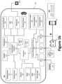
- FIG. 1 billustrates a block diagram of an example battery booster.
- FIG. 1 cillustrates a schematic diagram of an example battery booster.
- FIG. 1 dillustrates a communication network for use with the battery booster.
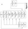
- FIG. 2illustrates a flow diagram of an example method for providing the jump-start function using a battery booster.
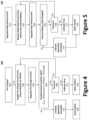
- FIG. 3illustrates a flow diagram of an example method for discharging and charging the battery booster.
- FIG. 4illustrates a flow diagram of an example pre-charge function.
- FIG. 5illustrates a flow diagram of an example current back-feed function.
- the word “exemplary”means “serving as an example, instance, or illustration.”
- the embodiments described hereinare not limiting, but rather are exemplary only. It should be understood that the described embodiments are not necessarily to be construed as preferred or advantageous over other embodiments.
- the terms “embodiments of the invention,” “embodiments,” or “invention”do not require that all embodiments of the invention include the discussed feature, advantage, or mode of operation.
- communicateand “communicating” as used herein, include both conveying data from a source to a destination and delivering data to a communications medium, system, channel, network, device, wire, cable, fiber, circuit, and/or link to be conveyed to a destination.
- communicationmeans data so conveyed or delivered.
- communicationsincludes one or more of a communications medium, system, channel, network, device, wire, cable, fiber, circuit, and/or link.
- Coupledmeans a relationship between or among two or more devices, apparatuses, files, circuits, elements, functions, operations, processes, programs, media, components, networks, systems, subsystems, and/or means, constituting any one or more of: (i) a connection, whether direct or through one or more other devices, apparatuses, files, circuits, elements, functions, operations, processes, programs, media, components, networks, systems, subsystems, or means; (ii) a communications relationship, whether direct or through one or more other devices, apparatuses, files, circuits, elements, functions, operations, processes, programs, media, components, networks, systems, subsystems, or means; and/or (iii) a functional relationship in which the operation of any one or more devices, apparatuses, files, circuits, elements, functions, operations, processes, programs, media, components, networks, systems, subsystems, or means depends, in whole or in part, on the operation of any one or more
- datameans any indicia, signals, marks, symbols, domains, symbol sets, representations, and any other physical form or forms representing information, whether permanent or temporary, whether visible, audible, acoustic, electric, magnetic, electromagnetic, or otherwise manifested.
- datais used to represent predetermined information in one physical form, encompassing any and all representations of corresponding information in a different physical form or forms.
- databasemeans an organized body of related data, regardless of the manner in which the data or the organized body thereof is represented.
- the organized body of related datamay be in the form of one or more of a table, map, grid, packet, datagram, frame, file, email, message, document, report, list, or any other form.
- networkincludes both networks and inter-networks of all kinds, including the Internet, and is not limited to any particular network or inter-network.
- processormeans processing devices, apparatuses, programs, circuits, components, systems, and subsystems, whether implemented in hardware, tangibly embodied software, or both, and whether or not it is programmable.
- processorincludes, but is not limited to, one or more computing devices, hardwired circuits, signal-modifying devices and systems, devices and machines for controlling systems, central processing units, programmable devices and systems, field-programmable gate arrays, application-specific integrated circuits, systems on a chip, systems comprising discrete elements and/or circuits, state machines, virtual machines, data processors, processing facilities, and combinations of any of the foregoing.
- a battery boostermay be used to start (a/k/a “boost”, “jump”, or “jump-start”) an engine operatively coupled to an external battery 104 (e.g., a 6V/12V/24V/48V nominal voltage vehicular battery or battery bank, which may be fully or partially depleted).
- an external battery 104e.g., a 6V/12V/24V/48V nominal voltage vehicular battery or battery bank, which may be fully or partially depleted.
- the battery booster 100may be further configured to charge the external battery 104 , and/or other electronic devices operatively coupled with the battery booster.
- Example vehicular batteriesinclude, without limitation, lead-acid batteries (e.g., wet/flooded batteries, calcium-calcium batteries, Valve-Regulated, Lead Acid (VRLA) batteries, gel cell, and Absorbed Glass Mat (AGM)) and other rechargeable batteries (e.g., lithium ion, lithium ion polymer, Nickel-Metal Hydride (NiMH), Nickel Cadmium (NiCd)).
- lead-acid batteriese.g., wet/flooded batteries, calcium-calcium batteries, Valve-Regulated, Lead Acid (VRLA) batteries, gel cell, and Absorbed Glass Mat (AGM)
- other rechargeable batteriese.g., lithium ion, lithium ion polymer, Nickel-Metal Hydride (NiMH), Nickel Cadmium (NiCd)
- Other electronic devices that may be operatively coupled with the battery boosterinclude, for example, portable electronic devices 152 (e.g., phones, tablet computers, portable computers, etc.), toys, etc.
- FIG. 1 aillustrates a front perspective view of an exemplary battery booster 100 .
- the battery booster 100may be, for example, a compact battery booster that is light weight and capable of hand-held use.
- the battery booster 100may generally comprise one or more housings 102 (e.g., a first housing 102 a and a second housing 102 b ) having, inter alia, a display device 114 , an AC input terminal 134 , a user interface 138 , a plurality of DC output terminals 136 , and/or a DC input terminal 154 .
- housings 102e.g., a first housing 102 a and a second housing 102 b
- the battery booster 100may generally comprise one or more housings 102 (e.g., a first housing 102 a and a second housing 102 b ) having, inter alia, a display device 114 , an AC input terminal 134 , a user interface 138 , a plurality of DC output terminal
- the plurality of DC output terminals 136may be used to charge (e.g., provide a charging current to external battery 104 or one or more portable electronic devices 152 ), boost (e.g., provide a boosting energy to a vehicle 106 /external battery 104 ), or otherwise power external devices, including portable electronic devices 152 , an external battery 104 , an engine, etc.
- the DC output terminals 136may comprise a DC booster output 136 a , a first DC accessory output 136 b , a second DC accessory output 136 c , etc.
- one or more of the first DC accessory output 136 b and the second DC accessory output 136 cmay be a USB Port, 12V port (e.g., a cigarette lighter socket), etc., a DC connector may be used for both DC input terminal 154 and DC output terminal 136 .
- While all of the components of the battery booster 100may be provided in a single housing 102 , in certain aspects, it may be advantageous to place certain components in a second housing 102 b (e.g., serving as an auxiliary housing), thereby reducing the size of the first housing 102 a (e.g., serving as a primary housing). For example, components that may be specific to jump starting an engine (as opposed to functions that may be used for other purposes, such as those for charging accessories, such as portable electronic devices 152 ) may be provided via the second housing 102 b to reduce the size necessary for the first housing 102 a.
- the battery booster 100can be removably coupled with a vehicle 106 or the external battery 104 (e.g., at its battery posts/terminals) of the vehicle 106 via a pair of electrical conductors 166 (e.g., positive and negative electrical conductors 166 a , 166 b ), which can be electrically coupled with the battery booster 100 at one of the DC output terminals 136 (e.g., the DC booster output 136 a ).
- Each of the electrical conductors 166may be, for example, a battery cable having a terminal connector at its distal end.
- the terminal connectorsmay be a set of battery clamps 168 (i.e., a positive clamp 168 a and a negative clamp 168 b ), a set of ring connectors, a plug (e.g., a quick connect plug), etc.
- the second housing 102 b(and associated components/circuitry) may be provided on one or both of the pair of electrical conductors 166 and position in line between the battery booster 100 (e.g., the detachable electrical ports/connectors 164 ) and the battery clamps 168 .
- a processor 128 and the power-management circuit 132may be provided via the second housing 102 b .
- the detachable electrical ports/connectors 164may be coupled, or integral with, the second housing 102 b rather than via a length of electrical conductors 166 .
- the battery booster 100can also measure, inter alia, the battery voltage of the external battery 104 and/or the current through the external battery 104 via the electrical conductors 166 a , 166 b .
- the electrical conductors 166 a , 166 bmay employ, for example, battery clamps 168 capable of Kelvin sensing (four terminal sensing).
- Kelvin sensingis an electrical impedance measuring technique that uses two separate pairs of current-carrying and voltage-sensing electrodes per conductor 166 a , 166 b to provide more accurate measurements than two-terminal (2T) sensing.
- each of the electrical conductors 166 a , 166 bmay employ multiple electrically isolated electrodes (i.e., cables, conductors, wires, etc.), whether sharing an insulated outer casing or otherwise bundled.
- each of the electrical conductors 166 a , 166 bmay employ two electrodes and provide two battery contacts (e.g., via battery clamps 168 capable of Kelvin sensing).
- the proximal end of the electrical conductors 166 a , 166 bmay be removably coupled with the battery booster 100 at the DC booster output 136 a via, for example, one or more detachable electrical ports/connectors 164 (e.g., EC5 connectors, barrel connectors, pin connectors, magnetic connectors, etc.).
- the proximal end of the electrical conductors 166 a , 166 bmay be fixedly coupled (i.e., non-removably coupled, for example, soldered) with the battery booster 100 .
- One or both of the housings 102 a , 102 b of the battery booster 100may further include one or more cable wrapping posts or another structure around which various cords may be wrapped, secured, or retracted.
- FIG. 1 billustrates a block diagram of an example battery booster 100 .
- the battery booster 100may comprise one or more processors 128 (e.g., a microprocessor, a central processing unit (CPU), etc.) to control the various operations of the battery booster 100 (e.g., to monitor and/or selectively charge or boost external devices).
- processors 128e.g., a microprocessor, a central processing unit (CPU), etc.
- CPUcentral processing unit
- the one or more processors 128may be operatively coupled to one or more memory devices, such as a read-only memory (ROM) 118 for receiving one or more instruction sets, a random access memory (RAM) 120 having a plurality of buffers for temporarily storing and retrieving information, and to an internal data storage device 122 (e.g., a hard drive, such a solid state drive, or other non-volatile data storage device, such as flash memory).
- a clock 130is also coupled to the processor 128 for providing clock or timing signals or pulses thereto.
- the battery booster 100includes one or more bus structures for interconnecting its various components.
- the various componentsare illustrated as being contained within a single housing 102 . Indeed, to increase ease of use in mobile applications, the various components of a battery booster 100 may be housed in a single housing 102 . A noted above, however, it is contemplated that certain components or functionality may be provided via a second housing. Further, while a single component may be illustrated, the described functionality may be distributed across multiple components. For example, while a single processor 128 is illustrated, a plurality of processors 128 may be used to operate the battery booster 100 ; whether in the same housing or separate housings (e.g., housings 102 a , 102 b ). Accordingly, serial communication may be employed to communicate information and data between multiple processors 128 that may be used.
- the internal power supply 158may be used to charge the portable electronic devices 152 , charge the external battery 104 , jump start the engine of the vehicle 106 associated with the external battery 104 , and/or power the components of the battery booster 100 (e.g., when disconnected from a DC power supply 156 and/or an AC power supply 148 ).
- the internal power supply 158may comprise one or more internal batteries 160 and/or one or more supercapacitors 162 .
- the one or more internal batteries 160 and one or more supercapacitors 162may be electrically coupled in parallel, where switches are used to selectively charge and/or discharge power thereto or therefrom.
- the switchesmay be mechanical switches (e.g., relays) or solid-state switches (e.g., transistors, such as a metal-oxide-semiconductor field-effect transistor (MOSFET)).
- the internal power supply 158should be sufficiently rated to boost (jump start) a vehicle 106 coupled to an external battery 104 .
- the internal battery 160may be rated at least 3,000 mAh, more preferably at least 10,000 mAh.
- a battery booster 100 having a 12,000 mAh internal battery 160for instance, may output 200 cranking amps/400 peak amps during the jump-start function, which is sufficient to start a vehicle 106 , but higher power internal batteries are contemplated for larger vehicles and trucks.
- the battery booster 100may have a 32,000 mAh internal battery 160 , for instance, may output 500 cranking amps/1,000 peak amps during the jump-start function.
- the internal battery 160may comprise a plurality of electrically coupled batteries (e.g., connected in parallel, or when multiple lower voltage batteries are to be summed, in series).
- the internal battery 160may be a rechargeable lithium battery for outputting a direct current (DC) voltage.
- Example lithium battery chemistriesinclude lithium iron phosphate (LiFePO 4 ), lithium polymer (Li-poly), lithium-cobalt oxide (LiCoO 2 ), lithium-titanate, lithium-nickel manganese cobalt oxide (LiNiMnCoO 2 or NMC), lithium iron magnesium phosphate (LiFeMgPO 4 ), lithium-manganese oxide (LiMnO 2 ), lithium ion manganese oxide (LiMn 2 O 4 , Li 2 MnO 3 , or LMO), etc.
- the internal battery 160need not be limited to a single battery or single battery cell.
- lithium iron phosphate batteriestypically have a nominal cell voltage of about 3.2V to 3.3V each, while lithium-titanate batteries have a nominal cell voltage of about 2.4 V.
- multiple lithium cellsmay be connected in series to achieve a desired nominal voltage for the internal battery 160 .
- the nominal cell voltageis 3.2V to 3.3V
- four cellsmay be connected to achieve a nominal voltage 12.8V to 13.2V for the internal battery 160 .
- the nominal voltage of the internal battery 160may be selected a function of the nominal voltage of the external battery 104 .
- the nominal voltage of the internal battery 160may be matched to (e.g., about the same as) the nominal voltage of the intended external battery 104 .
- the nominal voltage of the internal battery 160may be set to around 12 volts.
- the internal battery 160may comprise four battery cells connected in series, each having in a nominal cell voltage of about 3.2V to 3.3V (totaling 12.8V to 13.2V).
- the nominal voltages of the external battery 104 and the internal battery 160need not be matched (or similar). In fact, it can be advantageous to select a nominal voltage for the internal battery 160 that is greater than or otherwise exceeds the nominal voltage of the external battery 104 (e.g., by 15% to 50%, or at least 30%).
- One advantage of setting the voltage of the internal battery 160 higher than the intended external battery 104is the reduction is current requirements for the internal battery 160 during a jump start. That is, a battery with a higher nominal voltage can output a larger amount of power at a given current than a battery with a lower voltage at the same current.
- the nominal voltage of the internal battery 160may be set to around 16 volts.
- the internal battery 160may comprise five battery cells connected in series, each having in a nominal cell voltage of about 3.2V to 3.3V.
- the nominal voltage of the internal battery 160may be 33.34% higher than the nominal voltage of the external battery 104 .
- the nominal voltage of the internal battery 160may be greater than the nominal voltage of the external battery 104 by a different percentage, including for example, 10 to 50%, more preferably 20 to 40%.
- the nominal voltage of the intended external battery 104is 24 volts, while the nominal voltage of the internal battery 160 may be set to around 32 volts. In yet another example, the nominal voltage of the intended external battery 104 is 48 volts, while the nominal voltage of the internal battery 160 may be set to around 64 volts.
- An increased nominal voltageenables the internal battery 160 to expend additional power without dropping below a voltage (or power) necessary to jump start a vehicle 106 .
- the excess power afforced by the internal battery 160may be used to pre-charge the external battery 104 and/or preheat the external battery 104 or internal battery 160 , thereby making is easier to jump start the vehicle 106 .
- pre-charging the external battery 104can increase efficiency of the battery booster 100 .
- a supercapacitor 162may be used (whether alone or in addition to the internal battery 160 ) to supply a large amount of power that is sufficient time to jump start a vehicle 106 .
- the supercapacitor 162may be a single supercapacitor 162 or a bank of supercapacitors. For example, a plurality of supercapacitors may be coupled in parallel to aggregate the individual capacitors' capacitances.
- Supercapacitors 162are useful in that, unlike batteries, they do not necessarily suffer from ageing and temperature problems.
- a supercapacitor 162can hold a very high charge that can be released relatively quickly, thereby making it suitable for jump starting a vehicle 106 , since the vehicle 106 cranking operation lasts for a very short period of time during which high cranking power is required.
- supercapacitors 162are relatively small in size and can be employed in the battery booster 100 to provide sufficient cranking power to jump start a vehicle 106 .
- the battery booster 100may receive external power via a direct current (DC) input terminal 154 coupled to a DC power supply 156 and/or an alternating current (AC) input terminal 134 coupled to an AC power supply 148 .
- AC power supply 148may be wall current (e.g., 110 VAC)
- the DC power supply 156may be, for example, an automotive cigarette lighter (e.g., 12 VDC), a USB port (i.e., 5 VDC), etc.
- one of the plurality of DC output terminals 136may serve as both a DC input terminal 154 and a DC output terminal 136 .
- the battery booster 100may draw power from a device coupled to the DC output terminals 136 (functioning as a DC input terminal 154 ), or supply power to the device coupled to the DC output terminals 136 (functioning as a DC output terminal 136 ).
- the battery booster 100may draw a charging current to charge the internal power supply 158 from a vehicle 106 alternator via the DC booster output 136 a (through the set of battery clamps 168 , for example).
- the battery booster 100may draw a charging current to charge the internal power supply 158 from a power source coupled to the first DC accessory output 136 b , the second DC accessory output 136 c , etc.
- an AC-to-DC transformermay be provided, which may be integral with, or external to, the battery booster 100 .
- An AC-to-DC transformermay removably coupled with wall current (i.e., line current) and/or removably coupled to the battery booster 100 .
- a power inverter and AC output terminalmay be provided to output an AC voltage (e.g., a 110 VAC output).
- power from the DC power supply 156 or the internal battery 160may be processed (e.g., using a DC-to-AC inverter) and used to supply the AC voltage to the AC output terminal.
- the battery booster 100may draw the power needed to operate the components of the battery booster 100 from the external battery 104 and/or internal power supply 158 , thereby enabling the user to determine the status of the battery booster 100 (and state of charge, or other parameters, of the external battery 104 ) when the AC power supply 148 and the DC power supply 156 are unavailable.
- the battery booster 100may report a power supply failure (e.g., as an alert) to one or more portable electronic devices 152 (e.g., phones, tablet computers, portable computers, or other handheld terminals) within a battery monitoring network via a communication network 170 .
- portable electronic devices 152e.g., phones, tablet computers, portable computers, or other handheld terminals
- the battery booster 100may further include an input/output interface 126 that interfaces the processor 128 with one or more peripheral and/or communicative devices, such as a user interface 138 , a Global Positioning System (GPS) transmitter 140 , a wired link 142 , a wireless device 144 , a microphone 150 , and a speaker 124 , which may be used to signal an alert (e.g., charge complete, error, etc.) or other status information.
- the processor 128may be operatively coupled to a display device 114 via a display driver 116 .
- the display device 114may comprise, or otherwise employ, one or more light emitting diodes (LEDs) and/or a liquid crystal display (LCD) screen.
- the LCD screenmay be an alphanumeric segmented LCD display, or a matrix LCD display, such as those used on portable electronic devices.
- the LCD screenmay further provide touch screen functionality to facilitate user input device via a thin layer of sensing circuitry present either beneath the visible portion of a surface of the display device 114 , or as part of a thin, clear membrane overlying the display device 114 that is sensitive to the position of a pen or finger on its surface.
- the battery booster 100may employ multiple display devices 114 .
- a first display device 114may be provided on the first housing 102 a
- a second display device 114may be provided on the second housing 102 b
- the first and second display devices 114provide redundant information and/or function-specific information.
- the second display devicemay be specific to the jump-start function.
- the display driver 116may receive display data from the processor 128 via input/output interface 126 and display the display data via the display device 114 .
- interactive display device 114may be provided on the housing to provide the user with status information and/or input capability (e.g., via a touch screen or voice commands using, for example, wave files).
- Reminders, or other informationmay be displayed to the user, via the display device 114 , as a scrolling message or menu structure (e.g., a graphical user interface (GUI)).
- GUIgraphical user interface
- example flash memory devicesinclude, for example, memory cards, such as RS-MMC, miniSD, microSD, etc.
- the internal data storage device 122can function as an external hard drive or flash drive, thereby enabling the user to store digital files to the battery booster 100 .
- the usercan interchange, upgrade, or remove the memory card (e.g., if the battery booster 100 becomes defective) to avoid data loss.
- the display device 114may be used to display, for example, the contents of the internal data storage device 122 , the remaining storage capacity (e.g., as a percentage or in terms of available bytes), and, in certain aspects, the digital files themselves (e.g., photos may be displayed, files accessed, etc.).
- the battery booster 100may back up digital content stored to the portable electronic device 152 when the portable electronic device 152 is coupled to the battery booster 100 via, for example, a DC output terminal 136 that is a USB port.
- the display device 114may display the voltage of the external battery 104 .
- the display device 114may also indicate the state of charge of the external battery 104 in terms of percent of charge of the internal battery 160 .
- the display device 114may enter a sleep mode and will not display any messages until activity is detected (e.g., when devices are connected/disconnected from the battery booster 100 or the user interface 138 is actuated).
- the display device 114may remain blank and the voltage will not display, but a manual start procedure may be selected to enable the jump-start function (i.e., an override).
- the jump-start functionmay be used to start a vehicle 106 having an external battery 104 (e.g., a depleted automotive battery).
- the jump-start functioncauses the battery booster 100 to output a boosting current (e.g., 400+ peak amperes/200+ cranking amperes) via clamps coupled to the DC output terminal 136 .
- the internal battery 160may be replaced with a higher capacity battery to facilitate higher output currents.
- the supercapacitor 162may be discharged into the external battery 104 (e.g., together with the internal battery 160 ).
- a first LED of the display device 114may be illuminated to indicate that the internal battery 160 of the battery booster 100 is charging.
- a second LED on the unitmay be illuminated.
- a third LEDmay be illuminated.
- an LCD display or a single multi-color LEDmay be employed that changes color depending on the status of the battery booster 100 .
- the battery booster 100may be further equipped with a light 108 , which may function as a map light, flashlight, emergency light, etc.
- the light 108may be activated and deactivated via user interface 138 , such as a button, switch, etc.
- the light 108may be an LED that outputs, for example, 15 to 1,000 lumens.
- the display device 114may be configured to display, in addition to, or in lieu of, the LEDs, a number of messages to indicate the current status, or operation of the battery booster 100 to the user.
- the battery booster 100measures one or more parameters of the internal battery 160 , external battery 104 , or of the battery booster 100 . Parameters include, for example, voltage, power capacity, temperature, connection status, etc.
- the user interface 138may be used to enable the user to switch the output charge amperage (e.g., 1 A, 10 A, 50 A, 100 A, etc.) or another setting (e.g., charge, boost, other).
- Example user interface 138 devicesmay include, for example, physical buttons, physical switches, a digitizer (whether a touch pad, or transparent layer overlaying the display device 114 ), voice command (e.g., via the microphone 150 and speaker 124 ), and other input devices. For instance, using the digitizer, a user may control or interact with the battery booster 100 by writing or tapping on the display device 114 using, a pen, stylus, or finger.
- the user interface 138may be remotely situated and coupled to the battery booster 100 over a communication network 170 (e.g., as part of a remote interface device 172 , such as a mobile application).
- a communication network 170e.g., as part of a remote interface device 172 , such as a mobile application.
- the GPS transmitter 140may be used to track and/or monitor the location of the battery booster 100 and to relay the location information in the form of positional data (e.g., geographic coordinate system data or Internet Protocol (IP) address) to a booster management server or another device in battery charging system or via a communication network 170 .
- positional datae.g., geographic coordinate system data or Internet Protocol (IP) address
- IPInternet Protocol
- a computermay be configured to track the activities, location, and/or charge history of a particular battery booster 100 in a battery charging system.
- the positional datamay also be locally stored to the battery booster 100 (e.g., to internal data storage device 122 ).
- the wireless device 144may be configured to manage communication and/or transmission of signals or data between the processor 128 and another device (e.g., the remote interface device 172 via a communication network 170 or directly with a remote interface device 172 ) by way of a wireless transceiver.
- the wireless device 144may be a wireless transceiver configured to communicate via one or more wireless standards such as Bluetooth (e.g., short-wavelength, Ultra-High Frequency (UHF) radio waves in the Industrial, Scientific, and Medical (ISM) band from 2.4 to 2.485 GHz), near-field communication (NFC), Wi-Fi (e.g., Institute of Electrical and Electronics Engineers' (IEEE) 802.11 standards), etc.
- Bluetoothe.g., short-wavelength, Ultra-High Frequency (UHF) radio waves in the Industrial, Scientific, and Medical (ISM) band from 2.4 to 2.485 GHz
- NFCnear-field communication
- Wi-Fie.g., Institute of Electrical and Electronics Engineer
- wireless connectivitye.g., RF 900 MHz or Wi-Fi
- RF 900 MHz or Wi-Fimay be integrated with the battery booster 100 to provide remote monitoring and control of the battery booster 100 via one or more portable electronic devices 152 .
- a wireless device 144a user may be able to start and/or stop the charge cycle of the battery booster 100 or otherwise change the settings.
- a wired link 142may be provided to manage communication and/or transmission of signals or data between the processor 128 and another device via, for example, a data port 146 (e.g., RS-232, USB, and/or Ethernet ports) capable of being wiredly coupled with another data port 146 positioned outside the battery booster 100 housing.
- a USB port or 12V supplymay be provided as DC output terminals 136 on the charger to facilitate the charging of accessories, such as portable electronic devices 152 .
- the internal battery 160 of the battery booster 100may also be used as a power source for one or more DC accessories. Charging while operating the accessories can extend run time of the battery booster 100 , but will also extend recharge time. If the load exceeds the charging input amperage (e.g., 1 A), however, the accessory being charged may discharge the internal battery 160 .
- the DC accessory output port(e.g., first DC accessory output 136 b , the second DC accessory output 136 c ) may be a USB port that may provide, for example, 5 VDC at one or more amperages, including for example, 1.0 A, 2.1 A, 3.0 A, etc.
- a power button(or other user selectable element) may be provided via user interface 138 .
- the DC accessory output portmay be activated by pressing the power button, and disabled by, for example, pressing the power button a second time, two or more times in quick succession, or held for a predetermined period of time.
- the DC accessory output portmay be a 12 VDC power supply configured to output, for example, up to 12 VDC at 6.0 A.
- the battery booster 100may further comprise a plurality of sensors to provide measurement data descriptive of the surrounding environment.
- the DC accessory output portmay automatically shut off when no load is detected (e.g., after 5-10 minutes of a no load state).
- the DC booster output 136 amay remain active until the battery booster 100 reaches a low battery state (e.g., the charge level of the internal battery 160 is less than a predetermined threshold).
- the DC accessory output portmay provide a nominal voltage to match the external battery 104 (e.g., 12 VDC) and used to supply power to an integrated or remotely situated air compressor (e.g., for tire inflation).
- Matching (or exceeding) the nominal voltage of the external battery 104may further enable the DC accessory output port or DC booster output 136 a to function as a memory saver to the vehicle 106 (e.g., via an onboard diagnostics (OBD) port, cigarette lighter, etc.), thereby obviating the need to reprogram the vehicle 106 when the external battery 104 is disconnected or removed.
- OBDonboard diagnostics
- the DC accessory output portmay be limited to 12 VDC at 6.0 A with over current protection.
- a usermay wish to check the status of the internal power supply 158 , such as the charge status/level of the internal battery 160 or the supercapacitor 162 .
- a button(or other user selectable element) may be provided via user interface 138 that causes the status(es) to be displayed on the display device 114 .
- the usermay be instructed (e.g., via display device 114 ) to disconnect or turn off the battery booster 100 before actuating the button (or displaying the charge level).
- the display device 114can show the percent of charge (or an icon indicating the same) for the internal battery 160 and/or the supercapacitor 162 .
- the display device 114may display “100%” (or a solid battery icon) when the internal battery 160 is fully charged.
- the battery booster 100may include sensors 188 (e.g., a temperature sensor, humidity sensor, etc.), configured to monitor itself or other appliances or devices, either directly (e.g., using sensors 188 ) or wirelessly (e.g., using Wi-Fi).
- the processor 128may be configured to monitor, via one or more sensors 188 (whether local or remotely located), a temperature of the internal battery 160 or the external battery 104 .
- the battery booster 100may be configured to charge and monitor, in addition to automotive batteries, one or more portable electronic devices 152 being charged by said battery booster 100 .
- the battery booster 100may then charge or boost the external battery 104 as a function of the temperature or humidity of the environment or of the battery booster 100 .
- the battery booster 100may be used to pre-charge and/or pre-heat the external battery 104 and/or internal battery 160 in cold weather.
- Another temperature sensormay be provided to measure the temperature of the internal battery 160 , the external battery 104 , or another battery being charged (e.g., a lithium-ion battery of a portable electronic devices 152 ). If the measured temperature deviates from an operating range (i.e., a range in which the measured value is acceptable), the charging or boosting operating may be prohibited.
- a power-management circuit 132may be used to manage power needed to operate the battery booster 100 (and components thereof), start an engine, and to charge the external battery 104 , portable electronic devices 152 , or other device via a DC output terminals 136 .
- the power-management circuit 132may comprise a battery charge controller 178 , a supercapacitor charge controller 180 , power output controller 182 , and a single-ended primary-inductor converter (SEPIC) circuit 184 .
- SEPICsingle-ended primary-inductor converter
- a SEPIC circuit 184may be coupled to the DC input terminal 154 or the AC input terminal 134 (e.g., via a AC-to-DC converter 186 ) and used to charge the internal power supply 158 (e.g., via the battery charge controller 178 and the supercapacitor charge controller 180 ).
- the SEPIC circuit 184is a form of DC-to-DC converter that allows the electrical potential (voltage) at the output of the SEPIC circuit 184 to be greater than, less than, or equal to that at its input.
- the output of a SEPIC circuit 184is controlled by the duty cycle of a control transistor.
- a SEPIC circuit 184exchanges energy between capacitors and inductors in order to convert a variable input voltage (e.g., from the DC input terminal 154 or the AC-to-DC converter 186 ) to a predetermined output voltage that can be used to charge the internal power supply 158 , for example.
- the amount of energy exchangedis controlled by a switch, which may be a transistor such as a MOSFET.
- a SEPIC circuit 184enables a wide variation in input voltage both substantially higher and lower than the charge voltage of the internal power supply 158 .
- the variable input voltagecan be a voltage from a predetermined range, such as between 5 VDC to 20 VDC, thereby enabling internal battery 160 recharging functionality via a USB port, which is typically 5 VDC. That is, the input voltage may not be always known, but the predetermined range may be known.
- the SEPIC circuit 184may be shut off (e.g., bypassed) to facilitate a higher efficiency charge.
- the battery booster 100may bypass the SEPIC circuit 184 (e.g., via a switchable shunt), whereas, if 12 VDC power supply (e.g., a vehicle charger accessory) is used, the SEPIC circuit 184 may be employed.
- 12 VDC power supplye.g., a vehicle charger accessory
- the battery charge controller 178can be used to charge the internal battery 160 selectively, while the supercapacitor charge controller 180 can be used to charge the supercapacitor 162 selectively.
- the power output controller 182can be used to discharge the internal battery 160 and/or the supercapacitor 162 selectively into the external battery 104 , engine, or another load to be charge/boosted/started.
- the battery charge controller 178 , the supercapacitor charge controller 180 , and the power output controller 182may be controlled selectively by one or more processors 128 , for example, in accordance with instructions (e.g., software algorithms) stored to a memory device.
- the DC powermay be output to the external battery 104 or other devices by way of a DC output terminal 136 (e.g., battery electrical conductors 166 , battery clamps 168 , etc.).
- power-management circuit 132 and processor 128may control the charging operation of the external battery 104 to provide charging, maintaining, and, the jump-start function. While the power-management circuit 132 and processor 128 are illustrated as separate components, one of skill in the art would appreciate that power management functionality (e.g., battery charging, battery maintaining, etc.) may be provided as a single component that combines the functionality of the power-management circuit 132 and processor 128 .
- the power output controller 182may comprise, for example, one or more battery switches 190 , one or more supercapacitor switches 192 , one or more DC-to-DC converters 112 , and a pulse width modulation (PWM) driver 110 .
- the output powermay be controlled by switches and software.
- the one or more battery switches 190may be selectively controlled to output DC power from the internal battery 160 to one or more of the DC output terminals 136
- the one or more supercapacitor switches 192may be selectively controlled to output DC power from the supercapacitor 162 to one or more of the DC output terminals 136 (e.g., the DC booster output 136 a ).
- the battery switch(es) 190 and/or supercapacitor switch(es) 192may be controlled via the processor 128 and/or the PWM driver 110 .
- the speed (i.e., duty cycle) at which the battery switch(es) 190 and/or supercapacitor switch(es) 192 may be switches (i.e., opened and closed)can be controlled via the PWM driver 110 .
- the one or more battery switches 190 and the one or more supercapacitor switches 192may be selectively controlled as a function of one or more parameters, such as maximum current over time, maximum temperature of battery, maximum time alone and/or minimum voltage (with or without time). Thus, when a parameter value is exceeded (or a requirement isn't met), the output voltage may be shut off.
- the battery booster 100may include the ability to sense, or otherwise detect, that a battery (or other load/power supply) is coupled to the battery clamps 168 . When a battery is not detected, the power may be shut off; however, the user may be provided with a manual override option (e.g., by holding a button for a predetermined amount of time, such as 2 to 10 seconds, or about 5 seconds). In certain aspects, the battery booster 100 may not charge an external battery 104 when the external battery 104 is too hot or cold, thereby avoiding potential hazards, and maintaining efficiency.
- a DC-to-DC convertermay be omitted.
- the desired nominal voltage at the DC output terminals 136e.g., first DC accessory output 136 b , the second DC accessory output 136 c , etc.
- the desired nominal voltage at the DC output terminals 136e.g., first DC accessory output 136 b , the second DC accessory output 136 c , etc.
- the desired nominal voltage at the DC output terminals 136e.g., first DC accessory output 136 b , the second DC accessory output 136 c , etc.
- the DC-to-DC converter 112may convert the voltage of the power received from the internal battery 160 via the battery switches 190 from 16 volts to 5 volts.
- power from the internal power supply 158 or the power-management circuit 132may be allocated to the other components, including, inter alia, the processor 128 , input/output interface(s) 126 , etc.
- AC powermay be drawn from an AC power supply 148 , converted to DC power (via AC-to-DC converter 186 ), and used to charge the external battery 104 and/or the internal power supply 158 .
- the battery booster 100may be removably coupled with an AC power supply 148 located outside the housing 102 or housings 102 a , 102 b (e.g., a wall outlet) via an AC input terminal 134 and an AC-to-DC converter 186 .
- an AC wall chargermay receive 120 VAC from an electrical wall outlet and output, via an inverter, 12 VDC (or another desired DC voltage) to the input socket (e.g., DC input terminal 154 ) of the battery booster 100 .
- DC input powercan be received from a DC power supply 156 via DC input terminal 154 , or either AC power supply 148 via an AC-to-DC converter 186 .
- the DC input poweris received by SEPIC circuit 184 and output to the internal battery 160 and/or the supercapacitor 162 , in parallel, via an internal battery charge controller 178 and a supercapacitor charge controller 180 , respectively.
- the internal battery charge controller 178 and a supercapacitor charge controller 180may be used to monitor the parameters of the internal battery 160 and the supercapacitor 162 , such as the charge level or status.
- the supercapacitor 162 and internal battery 160may receive charging current from the DC input power.
- the power-management circuit 132 and processor 128may facilitate reverse hook-up protection, as well as automatic nominal battery voltage detection.
- the battery booster 100may further include the ability to sense the occurrence of a manual override, and, if voltage is still zero after engine start, the user may be instructed to check and replace the external battery 104 of the vehicle 106 . Further, an automatic shut-off function may be provided if a battery/load/power supply is not attached to the battery clamps 168 within a predetermined amount of time (e.g., about 1 to 60 minutes, more preferably about 1 to 30 minutes, most preferably about 1 to 15 minutes).
- the battery booster 100may further preheat a cold battery by, for example, running amperes though the battery, or an internal heater.
- the battery booster 100may further employ alternate power sources, such as a solar panel to enable battery maintaining and charging, as well as data monitoring through solar panels (e.g., one or more 12-14 Watt panels).
- solar panelse.g., one or more 12-14 Watt panels.
- solar cellsmay be used to charge or maintain fleet vehicles, such as vehicle dealership fleets, rental vehicles fleets, etc.
- the DC output terminal 136may be coupled to the external battery 104 (i.e., the battery to be charged/jumped, whether directly or indirectly) and the user interface 138 may be used to activate the boost feature.
- the jump-start functionmay also be selected by a user via a remote interface device 172 over a communication network 170 .
- the display device 114may indicate that the jump-start function cannot be performed at this time. If the battery clamps 168 are improperly connected (e.g., reverse polarity or disconnected), an aural alarm may sound, and the display device 114 may display a warning message, such as “Warning—Reverse Polarity” or “Warning—Battery Disconnected.” Conversely, if the battery clamps 168 are properly connected and the battery booster 100 is ready for use, the display device 114 may display a standby message, such as “Jump Start Ready.” If the jump-start function of the battery booster 100 is attempted twice within a predetermined time period (e.g., a minute), the jump-start function may be prohibited until the battery booster 100 has cooled down. During the cool down period, the display device 114 may display a cool down message, which may also indicate the remaining time for the cool down period.
- a predetermined time periode.g., a minute
- a manual start procedure(e.g., the manual override) may be selected to enable the jump-start function.
- the DC output terminal 136may be coupled to the external battery 104 and the user interface 138 may be used to activate the boost feature.
- the same buttonmay be used to trigger the jump-start function, but instead of a momentary press, the button may be pressed and held for a predetermined period of time (e.g., about 2 to 10 seconds, more preferably about 2-5 seconds) until the display device 114 displays the standby message.
- the manual start proceduremay override safety features to ensure that power is delivered regardless of connection status, in which case the battery booster 100 may energize the battery clamps 168 and cause sparking if they are touched together (i.e., shorted).
- the internal power supply 158may be charged.
- the usermay also charge the internal battery 160 while driving via the DC input terminal 154 (e.g., using a 12 VDC car charger that couples to the cigarette lighter).
- a 12 VDC input socketmay be used to recharge the battery booster 100 to a point where the internal power supply 158 is charged.
- the battery booster 100may then be used to jump start a vehicle 106 having an external battery 104 .
- the battery booster 100may be charged through the battery clamps 168 , which may be retractable and/or configured to be housed in a recess of the housing 102 of the battery booster 100 .
- chargingmay be accomplished by leaving the relay closed, thereby allowing the alternator in the vehicle 106 , which can provide up to 70 A, to rapidly charge the internal battery 160 .
- the battery booster 100may be configured to sense the current in a bidirectional manner through the battery clamps 168 (e.g., (1) to measure current going from the battery booster 100 into the external battery 104 , and (2) from the external battery 104 into the battery booster 100 ).
- a temperature sensormay be coupled to the battery booster 100 , whereby the relay is shut off if the battery booster 100 , or the internal battery 160 , reaches a predetermined shut-off temperature threshold.
- a benefit of maximizing the amount of current going back into the battery booster 100is that it yields a faster charge.
- the power output controller 182serves to provide power from the internal power supply 158 to the DC output terminals 136
- the power output controller 182may also be configured to back-feed power from the DC output terminals 136 to the internal power supply 158 , whether directly to the internal power supply 158 or via the SEPIC circuit 184 .
- the SEPIC circuit 184may draw current from the depleted external battery 104 (e.g., via the power output controller 182 ), which could be used to charge the internal power supply 158 , or portion thereof.
- a depleted external battery 104can typically charge the supercapacitor 162 ; therefore, when DC input power is unavailable at the DC input terminal 154 and the AC-to-DC converter 186 , for instance, the supercapacitor 162 may receive charging current from external battery 104 via the SEPIC circuit 184 .
- the external battery 104may be unable to start a vehicle 106 , but a portion of the remaining power may be drawn from the depleted external battery 104 and used to charge the supercapacitor 162 , which could then be used to boost the vehicle 106 .
- a supercapacitorWhen a supercapacitor is simply coupled to a depleted battery (e.g., external battery 104 ), the finite energy reserve is drained into the depleted battery, often lowering the voltage of the supercapacitor 162 to a level that cannot start an engine.
- the peak current that an internal battery 160 can supplymay be limited due to the temperature (i.e., in cold weather) that can affect the chemical reaction inside the jump starter battery. This limit in peak current may be such that the engine may not turn over. Therefore, both an internal battery 160 and a supercapacitor 162 , where the internal battery 160 cannot supply sufficient current to overcome the effects of the depleted external battery 104 , while the supercapacitor 162 may supply the peak current.
- a battery(e.g., the internal battery 160 , a small lithium battery, etc.) may be used in combination with the supercapacitor 162 to prevent the supercapacitor 162 from discharging the current back to the depleted external battery 104 until the battery booster 100 may determine that the user trying to start the vehicle 106 .
- the processor 128may determine that the user is attempting to start the vehicle 106 and the supercapacitor charge controller 180 may be instructed to electrically couple the supercapacitor 162 to the external battery 104 (via DC output terminal 136 ), thereby causing the supercapacitor 162 to quickly discharge into the external battery 104 , thereby enabling the vehicle 106 to start.
- the processor 128may be similarly configured to control the power output controller 182 , which enables the internal battery 160 to discharge into the external battery 104 .
- the power from the alternatormay back feed into the battery booster 100 and used to charge the internal power supply 158 (e.g., the internal battery 160 and/or the supercapacitor 162 ).
- the amount and duration of power back-fed from the DC output terminals 136 to the internal power supply 158may be controlled via the PWM driver 110 , for example.
- the internal battery 160 and a supercapacitor 162can each be recharged by a SEPIC circuit 184 , which may receive any input voltage between, for example, 5 VDC to 20 VDC.
- the internal battery charge controller 178recharges the internal battery 160 inside the battery booster 100 , while a supercapacitor charge controller 180 charges the supercapacitor 162 .
- the supercapacitor 162may also be recharged from the internal battery 160 , thereby providing multiple peak current starts.
- the jump-start functionis controlled by one or more processors 128 once the jump starter cables are attached to an external battery 104 and the jump-start function is engaged (either manually or automatically).
- the internal battery 160may be connected by a circuit with one or more switches (relays, transistors, etc.) to the external battery 104 of the vehicle 106 .
- the internal battery 160transfers energy into the external battery 104 and when the vehicle ignition is actuated (e.g., the key is turned, or the start button is pressed), current drawn from the starter motor will cause a voltage drop across the jump starter connection leads. This voltage drop may be detected by the one or more processors 128 , at which point the one or more processors 128 will electrically couple the supercapacitor in parallel with its internal battery 160 to supply the peak current required to start the engine.
- the jump starter functionis done and the battery booster 100 can recharge itself (e.g., the internal battery 160 and/or the supercapacitor 162 ) from an electrical connection to the electrical system of the vehicle 106 , which may continue until the internal battery 160 and/or the supercapacitor 162 are fully charged. After which the battery booster 100 may shut off its charging function, or the battery clamps 168 are removed. If the vehicle 106 does not start, once the starter is disengaged the voltage on the external battery 104 will stabilize and the supercapacitor 162 will recharge from the internal battery 160 (or any available power from the external battery 104 ), and prepare for the next attempt to start the engine, whereby the process is repeated.
- the starteris disengaged the voltage on the external battery 104 will stabilize and the supercapacitor 162 will recharge from the internal battery 160 (or any available power from the external battery 104 ), and prepare for the next attempt to start the engine, whereby the process is repeated.
- the charger cables (e.g., battery electrical conductors 166 ) of the battery booster 100may be fixedly coupled to the external battery 104 (e.g., via a bolt and ring terminals) and configured to quick connect to battery booster 100 (e.g., using quick connects/disconnect connectors).
- the quick connect connectorsmay not be compatible with different devices. Due to the inconvenience of disconnecting and reconnecting the fixedly coupled connections, it may be advantageous to use a charger cable that fixedly couples to the external battery 104 at one end, but provides a plurality of different connectors at the second end.
- the first endmay be fixedly coupled to a battery terminal through the ring terminals, while the second end may be provided with two connecters, namely (1) an EC5 (male) connector configured to couple with an EC5 (female) connector of the battery booster 100 and (2) a second (male) connector configured to couple with a second (female) connector of a battery charger/maintainer.
- One or more end capsmay be further provided to protect the unused connector from dirt and debris.
- Such a charger cablewould be of particular use for vehicles that are not often used and typically require jump starting.
- the charger cables of the battery booster 100may be configured to quick connect to battery booster 100 using magnetic connectors.
- the magnetic connectorsmay employ an electrical plug and receptacle that relies on magnetic force to maintain contact.
- a housing of the magnetic connectorsmay be physically shaped to ensure proper polarity when coupled (e.g., preventing the magnetic couplings from becoming coupled upside down). While two connectors are described, such a charger cable need not be limited to two connectors, nor should it be limited to the example connector types described.
- the entire battery booster 100may be permanently coupled to an external battery 104 or an electrical system of the vehicle 106 (e.g., installed under the hood or inside the vehicle).
- the battery booster 100may be fixedly coupled to the vehicle and remotely actuated using a physical button or controller (e.g., one positioned under the hood, on the dashboard, in the glove box, etc.), or wirelessly.
- the housing 102 of the battery booster 100may be fabricated to mitigate damage from engine temperature or engine fluids.
- Wireless controlmay be accomplished using, for example, a portable electronic device 152 that is communicatively coupled to the battery booster 100 via a communication network 170 .
- a smart phonemay wirelessly send a signal to the battery booster 100 , either directly or through the electrical system of the vehicle 106 , which causes the battery booster 100 to output boosting energy or charging energy to the external battery 104 of the vehicle 106 .
- the wireless communicationmay employ one or more wireless standards such as Bluetooth (e.g., short-wavelength, UHF radio waves in the ISM band from 2.4 to 2.485 GHz), NFC, Wi-Fi (e.g., IEEE 802.11 standards), etc.
- the battery booster 100may charge the internal battery 160 when the vehicle 106 is running via the electrical system of the vehicle 106 (e.g., 12 VDC supply).
- FIG. 1 dillustrates a communication network for use with the battery booster.
- the battery booster 100may communicate with a remote interface device 172 via a communication network 170 or directly with a remote interface device 172 .
- a usermay control the battery booster 100 , monitor live charging status updates, charging conditions, historic data, remotely update software and firmware, and stay connected with the battery booster 100 news and updates from the manufacturer via the communication network 170 and a booster management server 174 .
- an internal cellular modemmay be implemented that utilizes standards-based wireless technologies, such as 2G, 3G, 4G, Code Division Multiple Access (CDMA), and Global System for Mobile Communications (GSM), to provide wireless data communication over worldwide cellular networks.
- standards-based wireless technologiessuch as 2G, 3G, 4G, Code Division Multiple Access (CDMA), and Global System for Mobile Communications (GSM)
- An advantage of an internal cellular modemis that there is no reliance on a local network (e.g., wireless router, modem, etc.) of the user, thereby enabling communication between the battery booster 100 and communication network 170 , even in the event of a total power failure in at the location of user. Therefore, one or more routers 176 (e.g., Wi-Fi routers, cellular towers, etc.) may be used to connect the battery booster 100 to the communication network 170 .
- a local networke.g., wireless router, modem, etc.
- the battery booster 100may indicate to the user (e.g., via display device 114 or over a communication network 170 ) the number of ampere hours put into external battery 104 , and/or an indication of the state of health of the external battery 104 . For example, if customer inputs a battery size/model number, the battery booster 100 can use the battery capacity to provide the state of health.
- the battery booster 100may indicate to the user the state of charge or health of the internal battery 160 (e.g., the number of coulombs) via display device 114 .
- the battery charging methods or techniques employed by the battery booster 100can be any of a variety of charging techniques including conventional charging, fast charging, and the like.
- the battery booster 100may be further configured to determine, automatically, different battery chemistry (e.g., AGM, gel, lithium ion, etc.) and the nominal voltage of the external battery 104 .
- the charging characteristics of a battery chargermay be configured to match the battery chemistry of the battery to be charged.
- lead acid batteriesmay be charged with constant power, constant current, constant voltage, or combination thereof. Such batteries are known to be charged with both linear as well as switched-mode battery chargers.
- the identified battery chemistry and voltagemay be displayed on display device 114 .
- FIG. 2illustrates a flow diagram 200 of an example method for providing the jump-start function using a battery booster 100 .
- the processstarts at step 202 , which may be initiated by the user turning on the battery booster 100 or actuating a jump-start function button on the user interface 138 .
- the processor 128 of the battery booster 100may determine, using one or more sensors, whether the temperature of the internal battery 160 is within an operating range. For example, if the temperature of the internal battery 160 exceeds a first predetermined shut-off temperature threshold, a warning may be provided at step 220 indicating that the internal battery 160 is too hot. Similarly, if the temperature of the internal battery 160 does not meet a first predetermined shut-off temperature threshold, a warning may be provided at step 220 indicating that the internal battery 160 is too cold. Otherwise, the process proceeds to the next step.
- the processor 128 of the battery booster 100may determine whether the state of charge for the internal battery 160 is within an operating range. For example, if the state of charge of the internal battery 160 does not meet a predetermined charge level threshold, a warning may be provided at step 220 indicating that the internal battery 160 is not adequately charged. Otherwise, the process proceeds to the next step.
- the battery booster 100may provide the jump-start function even in the event the internal battery 160 is only partially charged, which may be satisfactory when the external battery 104 is nearly able to start the vehicle 106 .
- the processor 128 of the battery booster 100may determine whether the internal battery 160 is being charged. If the internal battery 160 is being charged, a warning may be provided at step 220 indicating that the internal battery 160 is being charged and cannot be used to provide the jump-start function. Otherwise, the process proceeds to the next step. In certain aspects, the battery booster 100 may provide the jump-start function even when the internal battery 160 is being charged.
- the processor 128 of the battery booster 100may determine whether an external battery 104 is coupled to the battery booster 100 (e.g., via battery clamps 168 coupled to the DC output terminal 136 ). If no external battery 104 is detected (e.g., by measuring a voltage or resistance across the battery terminal, such as the DC booster output 136 a ), a warning may be provided at step 220 indicating that the external battery 104 is not detected. Otherwise, the process proceeds to the next step.
- the processor 128 of the battery booster 100may determine whether an accessory is currently coupled to, or otherwise using, the battery booster 100 (e.g., via another DC output terminal 136 , such as the first DC accessory output 136 b , the second DC accessory output 136 c , etc.). If an accessory is detected (e.g., by detecting a load or other current draw at an output terminal), a warning may be provided at step 220 indicating that the internal battery 160 is in use and should not be used to provide the jump-start function. Otherwise, the process proceeds to the next step. In certain aspects, the battery booster 100 may provide the jump-start function even when another DC output terminal 136 is in use.
- the processor 128 of the battery booster 100may determine whether an external battery 104 is properly coupled to the battery booster 100 . If a reverse polarity condition is detected for the external battery 104 , a warning may be provided at step 220 indicating that the external battery 104 is improperly connected. Otherwise, the process proceeds to the next step.
- the processor 128 of the battery booster 100may determine whether the battery booster 100 is in a cool down period. For example, as noted above, if the jump-start function of the battery booster 100 is attempted twice within a predetermined time period (e.g., a minute), the jump-start function may be prohibited until the battery booster 100 has cooled down (i.e., the predetermined time period has elapsed). Accordingly, if the jump-start function has been performed within a predetermined period of time, a warning may be provided at step 220 indicating a cool down message, which may also indicate the remaining time for the cool down period. After the predetermined time period has elapsed at step 222 (e.g., using a timer), the process may proceed to the next step.
- a predetermined time periode.g., a minute
- the battery booster 100is ready to perform the jump-start function, whereby boosting energy may be output to the external battery 104 upon actuating the jump-start function button on the user interface 138 , or automatically.
- the boosting energymay be provided for a predetermined period of time, before shutting off.
- the boosting energymay be provided for 1 to 60 seconds, more preferably 5 to 30 seconds.
- the battery booster 100may further perform one or more other function prior to outputting a jump-start current.
- the battery booster 100may perform a pre-charge function.
- a pre-charge functionmay increase efficiency (or likelihood) of successfully jump starting a vehicle.
- the pre-charge functionmay be used to heat the glow plugs.
- a warningmay be provided at step 220 via one or more of a display device 114 , a speaker 124 , or to another device (e.g., a portable electronic device 152 ) via a communication network 170 .
- the messagemay indicate to the user one or more statuses/conditions of the internal battery 160 , external battery 104 , and/or of the battery booster 100 .
- the processmay be reset such that the process is repeated.
- the reset featuremay be manually triggered (e.g., via a button) or automatically once a predetermined condition is met. For example, if the temperature of the internal battery 160 is outside of the operating range, the system may be automatically reset once the temperature of the internal battery 160 returns to the operating range. If a reset is not selected at step 224 , the processed exits at step 226 .
- a manual override optionmay be selected (e.g., at any time) that causes the battery booster 100 to proceed to step 218 such that the battery booster 100 is ready to perform the jump-start function, regardless of the status of the internal battery 160 , external battery 104 , or of the battery booster 100 .
- the processor 128 of the battery booster 100may determine whether the voltage of the internal battery 160 or the external battery 104 exceeds a predetermined threshold, in which case charging and/or boosting is prohibited to prevent overcharging.
- the processor 128may control the power-management circuit 132 to selectively discharge the internal power supply 158 to one or more of the plurality of DC output terminals 136 .
- the processor 128may also control the power-management circuit 132 to charge the internal power supply 158 selectively via one or more of the plurality of DC output terminals 136 .
- FIG. 3illustrates a flow diagram 300 of an example method for discharging and charging the battery booster 100 (e.g., during a jump-start function).
- the processstarts at step 302 .
- the jump-start functionmay be initiated by the user, turning on the battery booster 100 , or actuating a jump-start function button on the user interface 138 .
- the processor 128may determine whether a pre-charge function is selected.
- the pre-charge functionmay be set via the user from the user interface 138 (or remote interface device 172 ). In certain aspects, the pre-charge function may be a default operation. If the pre-charge function is selected at step 304 , the process proceeds to step 306 , whereby the pre-charge function is performed before proceeding to step 308 (see FIG. 4 ). Otherwise, if the pre-charge function is not selected at step 304 , the process may proceed directly to step 308 .
- the battery booster 100may, via processor 128 , close one or more switches to provide the jump-start current to the external battery 104 , for example, using a pair of battery clamps 168 coupled to the DC booster output 136 a via battery electrical conductors 166 .
- the processor 128may selectively control (e.g., open or close) one or more switches in the power-management circuit 132 to pass the jump-start current from the internal power supply 158 to the DC booster output 136 a .
- the one or more battery switches 190may be selectively controlled to output DC power from the internal battery 160 to one or more of the DC booster output 136 a , while one or more supercapacitor switches 192 may be selectively controlled to output (i.e., discharge) DC power from the supercapacitor 162 to the DC booster output 136 a .
- the battery switches 190 and supercapacitor switches 192may be independently controlled.
- the battery switches 190may be actuated (closed) to transfer an amount of power from the internal battery 160 to the DC booster output 136 a before actuating (closing) the supercapacitor switches 192 to discharge the supercapacitor 162 to the DC booster output 136 a .
- the battery switches 190 and supercapacitor switches 192may be simultaneously actuated, thereby simultaneously discharging the internal battery 160 and the supercapacitor 162 to the DC booster output 136 a .
- the supercapacitor switches 192may be opened, at which point the supercapacitor 162 may be recharged (e.g., via the internal battery 160 ).
- the battery booster 100may, via processor 128 , determine whether the engine of the vehicle 106 coupled to the external battery 104 has started. For example, the processor 128 may detect a voltage spike using one or more sensors 188 (e.g., voltage or current sensors), which is indicative of the engine starting and driving the alternator of the vehicle 106 .
- sensors 188e.g., voltage or current sensors
- the voltage spike generated when the vehicle 106 starts during a jump-starting operationcan be harmful to the vehicle 106 (e.g., harmful to its onboard computers, electronics, entertainment system, etc.). That is, the combination of power from the battery booster 100 and power from the alternator can result in a power surge.
- the battery booster 100may be configured with a current back-feed function to back feed power from the vehicle to the internal power supply 158 . In other words, upon starting, the battery booster 100 may transform from a power source to a load, thereby absorbing the voltage spike.
- the processor 128may determine whether a current back-feed function is selected.
- the current back-feed functionmay be set via the user from the user interface 138 (or remote interface device 172 ). In certain aspects, the current back-feed function may be a default operation. If the current back-feed function is selected at step 314 , the process proceeds to step 316 , whereby the current back-feed function is performed before proceeding to step 308 (see FIG. 5 ). Otherwise, if the current back-feed function is not selected at step 304 , the process may proceed directly to step 318 .
- the battery booster 100may, via processor 128 , open the one or more switches to discontinue supply of the jump-start current to the external battery 104 .
- the processor 128may selectively control (e.g., open or close) one or more switches in the power-management circuit 132 to prohibit current flow between the internal power supply 158 and the DC booster output 136 a .
- the process of discharging and charging the battery booster 100may end at step 320 .
- FIG. 4illustrates a flow diagram of an example pre-charge function (e.g., step 308 ).
- the battery booster 100may, via processor 128 , close one or more switches to provide the pre-charge current to the external battery 104 , for example, using the pair of battery clamps 168 coupled to the DC booster output 136 a via battery electrical conductors 166 .
- the processor 128may selectively control (e.g., open or close) one or more switches in the power-management circuit 132 to pass the pre-charge current from the internal power supply 158 to the DC booster output 136 a.
- the processor 128may regulated the pre-charge current.
- the amperage of the pre-charge currentmay be lower than the jump-start current (e.g., 1 to 25 amps).
- the amperagemay be adjusted or regulated via, for example, one or more converters.
- the battery booster 100may, via processor 128 , open and close the battery switches 190 at a predetermined frequency to achieve a duty cycle that provides a desired regulated pre-charge current from the internal battery 160 to an external battery 104 that is electrically coupled to the DC booster output 136 a .
- the battery switches 190may be fully closed for a predetermined period of time to couple the internal battery 160 directly to the DC booster output 136 a , in which case the pre-charge current would be effectively a jump-start current for the predetermined period of time.
- the pre-charge currentmay be provided to the external battery 104 that is electrically coupled to the DC booster output 136 a until a predetermined condition (e.g., a predetermined battery condition) is met at step 406 . If the condition is met (i.e., a threshold is met), the process proceeds to step 410 , otherwise, the process may proceed to step 408 .
- the conditionmay relate to a voltage of the external battery 104 , the amount of current (i.e., amperes) provided to the external battery 104 , a temperature of the external battery 104 , a temperature of the internal battery 160 , a time duration, etc.
- the pre-charge currentmay be provided to the external battery 104 until a predetermined threshold voltage, threshold temperature, threshold amperes, or time has elapsed.
- a predetermined threshold voltage, threshold temperature, threshold amperes, or timeis an advantage of the pre-charge function.
- the temperature of the internal battery 160will increase as the internal battery 160 discharges into the external battery 104 .
- Increasing the temperature of the internal battery 160 to a predetermined temperatureimproves discharge efficiency of the internal battery 160 .
- the pre-charge functionmay continue until the voltage of the internal battery 160 equalizes with the voltage of the external battery 104 .
- the pre-charge currentmay be supplied as a function of the temperature of the environment.
- the processor 128may collect temperature readings from one or more sensors 188 , where the duration of the pre-charge function may be a function of the temperature. That is, a pre-charge current may be supplied for a longer period of time during the pre-charge function when the temperature (e.g., as reported by the sensors 188 ) is low.
- the battery booster 100may indicate that the pre-charge operation is completed at step 410 .
- the indicationmay aural or visual (e.g., illuminating a light, displaying text, displaying an icon, etc.) and be provided via, for example, a display device 114 , a speaker 124 , or another device (e.g., a portable electronic device 152 ) via a communication network 170 .
- the processmay then proceed to step 308 .
- the battery booster 100may determine whether a timeout condition exists at step 408 .
- the power-management circuit 132may be configured to pass the pre-charge current from the internal power supply 158 to the DC booster output 136 a for only a predetermined amount of time.
- the predetermined amount of timemay be, for example, 1 second to 300 seconds. If the predetermined amount of time has not yet elapsed at step 408 , the process may return to step 402 . If the predetermined amount of time has elapsed at step 408 , the process may proceed to step 412 .
- the battery booster 100may indicate that the pre-charge operation has failed.
- the indicationmay aural or visual and be provided via, for example, a display device 114 , a speaker 124 , or another device (e.g., a portable electronic device 152 ) via a communication network 170 .
- the processmay then proceed to step 318 , where the battery booster 100 may, via processor 128 , open the one or more switches to discontinue supply of the jump-start current to the external battery 104 .
- FIG. 5illustrates a flow diagram of an example current back-feed function (e.g., step 316 ). If the current back-feed function (e.g., step 316 ) is selected at step 314 , the battery booster 100 may, via processor 128 , open (or hold open) one or more switches to receive a back-feed current from vehicle 106 (e.g., the vehicle's 106 alternator coupled to the external battery 104 ), for example, using the pair of battery clamps 168 coupled to the DC booster output 136 a via battery electrical conductors 166 .
- vehicle 106e.g., the vehicle's 106 alternator coupled to the external battery 104
- the processor 128may selectively control (e.g., open or close) one or more switches in the power-management circuit 132 to receive the back-feed current from the DC booster output 136 a and direct it to the internal power supply 158 .
- the processor 128may regulated the back-feed current.
- the battery booster 100may, via processor 128 , open and close the battery switches 190 at a predetermined frequency to achieve a duty cycle that provides a desired regulated back-feed current from the internal battery 160 to an external battery 104 that is electrically coupled to the DC booster output 136 a .
- a pulse width modulation (PWM) driver 110may be used to control the duty cycle.
- the battery switches 190may be fully closed for a predetermined period of time to couple the internal battery 160 directly to the DC booster output 136 a , thereby absorbing current.
- the predetermined period of timemay be, for example, up to 60 seconds, up to 30 seconds, or up to 15 seconds.
- the back-feed currentmay be provided to the internal battery 160 until a predetermined booster condition is met at step 506 . If the condition is met (i.e., a threshold is met), the process proceeds to step 510 , otherwise, the process may proceed to step 508 .
- the conditionmay relate to a voltage of the internal battery 160 , the amount of current (i.e., amperes) provided to the internal battery 160 , a temperature of the internal battery 160 , a time duration, etc.
- the back-feed currentmay be provided to the internal battery 160 until a predetermined threshold voltage, threshold temperature, threshold amperes, or time has elapsed.
- Another advantage of providing the back-feed current to the battery booster 100is that the internal power supply 158 can be charged, thereby reducing the amount of time needed to recharge the internal power supply 158 using other means.
- the battery booster 100may indicate that the back-feed function is completed at step 510 .
- the indicationmay aural or visual and be provided via, for example, a display device 114 , a speaker 124 , or another device (e.g., a portable electronic device 152 ) via a communication network 170 .
- the processmay then proceed to step 318 , where the battery booster 100 may, via processor 128 , open the one or more switches to discontinue supply of the jump-start current to the external battery 104 .
- the battery booster 100may determine whether a timeout condition exists at step 508 .
- the power-management circuit 132may be configured to pass the back-feed current from the internal power supply 158 to the DC booster output 136 a for only a predetermined amount of time.
- the predetermined amount of timemay be, for example, 1 second to 300 seconds, 2 seconds to 150 seconds, 2 seconds to 60 seconds, or 2 seconds to 30 seconds. If the predetermined amount of time has not yet elapsed at step 508 , the process may return to step 502 . If the predetermined amount of time has elapsed at step 508 , the process may proceed to step 512 .
- the battery booster 100may indicate that the back-feed function has failed.
- the indicationmay aural or visual and be provided via, for example, a display device 114 , a speaker 124 , or another device (e.g., a portable electronic device 152 ) via a communication network 170 .
- the processmay then proceed to step 318 , where the battery booster 100 may, via processor 128 , open the one or more switches to discontinue supply of the jump-start current to the external battery 104 .
Landscapes
- Engineering & Computer Science (AREA)
- Chemical & Material Sciences (AREA)
- Mechanical Engineering (AREA)
- Power Engineering (AREA)
- Combustion & Propulsion (AREA)
- General Engineering & Computer Science (AREA)
- Manufacturing & Machinery (AREA)
- Chemical Kinetics & Catalysis (AREA)
- Electrochemistry (AREA)
- General Chemical & Material Sciences (AREA)
- Materials Engineering (AREA)
- Transportation (AREA)
- Charge And Discharge Circuits For Batteries Or The Like (AREA)
Abstract
Description
Claims (18)
Priority Applications (2)
| Application Number | Priority Date | Filing Date | Title |
|---|---|---|---|
| US16/556,525US11674490B2 (en) | 2018-08-30 | 2019-08-30 | Multifunctional battery booster |
| US18/208,649US12421928B2 (en) | 2018-08-30 | 2023-06-12 | Multifunctional battery booster |
Applications Claiming Priority (2)
| Application Number | Priority Date | Filing Date | Title |
|---|---|---|---|
| US201862725164P | 2018-08-30 | 2018-08-30 | |
| US16/556,525US11674490B2 (en) | 2018-08-30 | 2019-08-30 | Multifunctional battery booster |
Related Child Applications (1)
| Application Number | Title | Priority Date | Filing Date |
|---|---|---|---|
| US18/208,649ContinuationUS12421928B2 (en) | 2018-08-30 | 2023-06-12 | Multifunctional battery booster |
Publications (2)
| Publication Number | Publication Date |
|---|---|
| US20200072177A1 US20200072177A1 (en) | 2020-03-05 |
| US11674490B2true US11674490B2 (en) | 2023-06-13 |
Family
ID=69642207
Family Applications (2)
| Application Number | Title | Priority Date | Filing Date |
|---|---|---|---|
| US16/556,525ActiveUS11674490B2 (en) | 2018-08-30 | 2019-08-30 | Multifunctional battery booster |
| US18/208,649ActiveUS12421928B2 (en) | 2018-08-30 | 2023-06-12 | Multifunctional battery booster |
Family Applications After (1)
| Application Number | Title | Priority Date | Filing Date |
|---|---|---|---|
| US18/208,649ActiveUS12421928B2 (en) | 2018-08-30 | 2023-06-12 | Multifunctional battery booster |
Country Status (1)
| Country | Link |
|---|---|
| US (2) | US11674490B2 (en) |
Cited By (3)
| Publication number | Priority date | Publication date | Assignee | Title |
|---|---|---|---|---|
| US20220123581A1 (en)* | 2020-10-20 | 2022-04-21 | Schumacher Electric Corporation | Battery Booster |
| US20220242341A1 (en)* | 2019-06-26 | 2022-08-04 | Volvo Truck Corporation | Vehicle power supply system, vehicle comprising such system and method for recharging a vehicle battery |
| US11940338B2 (en)* | 2022-05-30 | 2024-03-26 | Wistron Corp. | Electric-carrier power-supply device and method for detecting potential power failure |
Families Citing this family (27)
| Publication number | Priority date | Publication date | Assignee | Title |
|---|---|---|---|---|
| CN206664505U (en)* | 2017-04-17 | 2017-11-24 | 汪玉华 | Condenser type automobile emergency starter |
| CN111819751B (en)* | 2018-08-30 | 2024-03-19 | 深圳市华思旭科技有限公司 | Vehicle-mounted starting power supply |
| US10998757B2 (en)* | 2018-11-25 | 2021-05-04 | Vijay Brazanton Almeida | Smartphone interfaced automotive smart battery with self boosting capability |
| JP7232095B2 (en)* | 2019-03-26 | 2023-03-02 | 株式会社Subaru | Control device |
| US11637436B2 (en)* | 2019-10-09 | 2023-04-25 | Jiasheng Wu | Automobile jumpstart adapter for an external battery |
| US11598306B2 (en)* | 2020-01-17 | 2023-03-07 | Martin Koebler | Emergency start |
| US11591996B2 (en)* | 2020-01-17 | 2023-02-28 | Martin Koebler | Emergency start |
| WO2021226319A1 (en)* | 2020-05-07 | 2021-11-11 | Milwaukee Electric Tool Corporation | Vehicle battery jump starter with multiple battery pack compatibility |
| US20210408512A1 (en)* | 2020-06-25 | 2021-12-30 | Mohamed Bayoumi Mahmoud Abuelazm | Vehicle dashboard built-in battery jumper rack |
| CN114189000A (en)* | 2020-09-14 | 2022-03-15 | 深圳市华思旭科技有限公司 | Intelligent control system, emergency starting power supply and intelligent storage battery clamp |
| US11305709B1 (en)* | 2020-10-20 | 2022-04-19 | John Vernon | Integrated vehicular battery booster and jump starter |
| US11552484B2 (en)* | 2020-10-29 | 2023-01-10 | Deltran Operations Usa, Inc. | Systems and methods for operating a solar charger system for providing battery and circuit protection |
| TWI745228B (en)* | 2021-02-01 | 2021-11-01 | 低碳動能開發股份有限公司 | Super capacitor modularized power supply rescue device and remote control method |
| CN112965469A (en)* | 2021-03-24 | 2021-06-15 | 深圳市道通科技股份有限公司 | Automobile diagnosis device, control method and storage medium |
| US11527897B1 (en)* | 2021-05-21 | 2022-12-13 | Deltran Operations Usa, Inc. | Battery charger and engine jump start system with automatic operating mode via a single output receptacle |
| CN113328655B (en)* | 2021-05-31 | 2023-11-28 | 三一重机有限公司 | Cold start circuit and excavator |
| CN113708600A (en)* | 2021-07-20 | 2021-11-26 | 林梓凡 | High-frequency current source switch DC converter |
| US11545842B1 (en)* | 2021-07-20 | 2023-01-03 | Grepow Inc | Vehicle jump starter device |
| WO2023015828A1 (en)* | 2021-08-11 | 2023-02-16 | 广东电将军能源有限公司 | Portable backup starting device and backup starting tool for vehicle |
| US12228101B2 (en)* | 2021-08-11 | 2025-02-18 | Guangdong Boltpower Energy C0., Ltd. | Portable standby starting device and standby starting tool for vehicle |
| JP7434454B2 (en)* | 2021-08-11 | 2024-02-20 | 広東電将軍能源有限公司 | Portable preliminary starting device and preliminary starting tool for vehicles |
| GB2609975B (en)* | 2021-08-20 | 2023-11-15 | Jaguar Land Rover Ltd | Extended-use mode for an ancillary vehicle function |
| US20230333527A1 (en)* | 2022-04-13 | 2023-10-19 | Dell Products L.P. | Enhanced capacity management of power supplies in response to environmental conditions |
| CN114884173A (en)* | 2022-06-06 | 2022-08-09 | 东莞市航车宝未来科技有限公司 | Safety control circuit and be equipped with emergent start-up of car of this circuit and press from both sides |
| EP4485746A1 (en)* | 2023-06-20 | 2025-01-01 | Guangdong Aoyun Technology Co., Ltd. | Energy storage power supply |
| WO2025076385A1 (en)* | 2023-10-06 | 2025-04-10 | Dopollo Innovations, Inc | Automobile jumpstart adapter including supercapacitors for voltage conversion in emergency start-up of vehicles |
| CN221467416U (en)* | 2023-11-16 | 2024-08-02 | 深圳市詹普斯达科技有限公司 | Emergency starting power supply for automobile |
Citations (171)
| Publication number | Priority date | Publication date | Assignee | Title |
|---|---|---|---|---|
| US3343057A (en) | 1965-02-15 | 1967-09-19 | Litton Prec Products Inc | Booster supply service vehicles with polarity protection |
| US3590357A (en) | 1969-11-05 | 1971-06-29 | Donald Reid | Battery booster |
| US3778632A (en) | 1971-09-14 | 1973-12-11 | Bogne John C | Emergency starting power for engines |
| US3950688A (en) | 1974-02-06 | 1976-04-13 | Dav | Portable auxiliary current source including a battery and charger |
| US4079304A (en) | 1976-08-03 | 1978-03-14 | Brandenburg John D | Battery jumper system for vehicles |
| US4829223A (en) | 1988-01-25 | 1989-05-09 | Broberg Daniel M | Vehicle battery charger |
| US4925750A (en) | 1987-07-10 | 1990-05-15 | Power Cell, Inc. | Reserve battery |
| US4983473A (en) | 1989-06-16 | 1991-01-08 | Smith James L | Auxiliary power source with charger and integral light source |
| US5194799A (en) | 1991-03-11 | 1993-03-16 | Battery Technologies Inc. | Booster battery assembly |
| US5589292A (en) | 1993-10-25 | 1996-12-31 | Booster Pac International Corporation | Portable booster battery |
| US5678077A (en) | 1995-09-25 | 1997-10-14 | Minolta Co., Ltd. | Electronic flash device and camera equipped with said device |
| US5741305A (en) | 1996-05-06 | 1998-04-21 | Physio-Control Corporation | Keyed self-latching battery pack for a portable defibrillator |
| US5764030A (en) | 1997-03-14 | 1998-06-09 | International Components Corporation | Microcontrolled battery charger |
| US5793185A (en) | 1997-06-10 | 1998-08-11 | Deltona Transformer Corporation | Jump starter |
| US5796255A (en) | 1996-04-06 | 1998-08-18 | Mcgowan; Ricky Dean | Electronic controlled, spark free booster cable system |
| US5814972A (en) | 1993-05-13 | 1998-09-29 | Canon Kabushiki Kaisha | Electronic apparatus having multiple loads, driven by plural batteries |
| US6020719A (en) | 1997-11-12 | 2000-02-01 | Nec Corporation | Secondary battery unit using electric double layer condenser |
| US6130519A (en) | 1998-10-16 | 2000-10-10 | Century Mfg. Co. | Portable battery charger including auto-polarity switch |
| US6140797A (en) | 1998-10-08 | 2000-10-31 | Dunn; James P. | Compact improved autonomous auxiliary engine starting apparatus |
| US6155870A (en) | 1998-04-17 | 2000-12-05 | Clarke Power Products, Inc. | Battery jump start system with integral cord storage pouch |
| US6198249B1 (en) | 2000-02-15 | 2001-03-06 | Mark W. Kroll | Thermal booster battery system |
| US6215273B1 (en) | 2000-03-23 | 2001-04-10 | Jack Shy | Portable electrical energy source |
| US20010038276A1 (en)* | 2000-03-20 | 2001-11-08 | Oivind Resch | Device for charging a starting battery in a vehicle |
| US20020008523A1 (en) | 1998-07-27 | 2002-01-24 | Klang James K. | Apparatus and method for carrying out diagnostic tests on batteries and for rapidly charging batteries |
| US6344733B1 (en) | 2000-01-31 | 2002-02-05 | Snap-On Technologies, Inc. | Portable jump-starting battery pack with charge monitoring system |
| US6356050B1 (en) | 2000-04-06 | 2002-03-12 | Rally Manufacturing, Inc. | Portable booster supply with wireless remote control activation |
| US20020041174A1 (en)* | 2000-10-10 | 2002-04-11 | Bruce Purkey | Apparatus for providing supplemental power to an electrical system and related methods |
| US6377029B1 (en) | 2000-04-26 | 2002-04-23 | Vector Manufacturing, Ltd. | Current regulated mobile battery booster |
| US6380712B2 (en) | 2000-04-10 | 2002-04-30 | Kenneth C. Murphy | Battery booster with preconditioning and temperature compensation |
| US6384573B1 (en) | 1998-11-12 | 2002-05-07 | James Dunn | Compact lightweight auxiliary multifunctional reserve battery engine starting system (and methods) |
| US20020145404A1 (en) | 2001-04-05 | 2002-10-10 | Electrofuel, Inc. | Energy storage device and loads having variable power rates |
| US6466025B1 (en) | 2000-01-13 | 2002-10-15 | Midtronics, Inc. | Alternator tester |
| US20020167296A1 (en) | 2001-05-11 | 2002-11-14 | Toyota Jidosha Kabushiki Kaisha | Refresh charge control device and method |
| US20030052645A1 (en) | 2001-09-18 | 2003-03-20 | Hiroshi Sasaki | Power source circuit, electronic device being equipped with same power source circuit and control method of power source circuit |
| US20030137277A1 (en) | 2000-03-01 | 2003-07-24 | Iichiro Mori | Battery and maintenance service system for power supply device |
| US20030169022A1 (en) | 2000-05-15 | 2003-09-11 | Turner Geoffrey Alan | Power supply |
| US6625477B1 (en) | 1996-06-12 | 2003-09-23 | Ericsson Inc. | Apparatus and method for identifying and charging batteries of different types |
| US6679212B2 (en) | 2000-03-24 | 2004-01-20 | Goodall Manufacturing, Llc | Capacitive remote vehicle starter |
| US20040052022A1 (en) | 2002-09-13 | 2004-03-18 | Laraia J. Marcos | Integrated overvoltage and reverse voltage protection circuit |
| US6756764B2 (en) | 2001-03-05 | 2004-06-29 | John S. Smith | Portable jumper system and method |
| US20040130298A1 (en) | 2002-02-19 | 2004-07-08 | Michael Krieger | Microprocessor controlled booster apparatus with polarity protection |
| US6788025B2 (en) | 2001-06-22 | 2004-09-07 | Midtronics, Inc. | Battery charger with booster pack |
| US6799993B2 (en) | 2002-12-20 | 2004-10-05 | Vector Products, Inc. | Portable electrical energy source |
| US6819010B2 (en) | 2001-03-08 | 2004-11-16 | Kold Ban International, Ltd. | Vehicle with switched supplemental energy storage system for engine cranking |
| US20040239290A1 (en) | 2003-03-21 | 2004-12-02 | Vector Product, Inc. | Combination jump starter and high frequency charger |
| US20040251876A1 (en) | 2001-06-22 | 2004-12-16 | Midtronics, Inc. | Apparatus and method for counteracting self discharge in a storage battery |
| US6871151B2 (en) | 1997-11-03 | 2005-03-22 | Midtronics, Inc. | Electronic battery tester with network communication |
| US20050065558A1 (en) | 2003-09-19 | 2005-03-24 | Powers Daniel J. | External defibrillator having a removable battery pack using off-the-shelf cells |
| US6871625B1 (en) | 2004-01-26 | 2005-03-29 | Kold Ban International, Ltd. | Vehicle with switched supplemental energy storage system for engine cranking |
| US20050088626A1 (en) | 2003-10-28 | 2005-04-28 | Shin-Pin Huang | Projection device with battery pack |
| US6943666B2 (en) | 2001-02-15 | 2005-09-13 | Agere Systems, Inc. | Recharging key based wireless device |
| US20050258797A1 (en)* | 2004-05-19 | 2005-11-24 | Chien-Ming Hung | Portable emergency vehicle battery charger |
| US20050285445A1 (en) | 2003-01-06 | 2005-12-29 | Johnson Controls Technology Company | Battery management system |
| US20060006841A1 (en) | 2004-07-12 | 2006-01-12 | Samsung Electronics Co., Ltd. | Battery pack and electronic device using the same |
| US6988475B2 (en) | 2000-08-31 | 2006-01-24 | Kold Ban International, Ltd. | Methods for starting an internal combustion engine |
| US7015674B2 (en) | 2001-06-22 | 2006-03-21 | Midtronics, Inc. | Booster pack with storage capacitor |
| US20060133007A1 (en) | 2004-12-07 | 2006-06-22 | Lih-Ren Shiue | Power supply apparatus and power supply method |
| US20060244412A1 (en) | 2005-05-02 | 2006-11-02 | Bon-Aire Industries, Inc. | Automotive jump-starter with polarity detection, current routing circuitry and lighted cable connection pairs |
| US7161476B2 (en) | 2000-07-26 | 2007-01-09 | Bridgestone Firestone North American Tire, Llc | Electronic tire management system |
| US7161253B2 (en) | 2003-08-06 | 2007-01-09 | Briggs & Stratton Corporation | Portable power source |
| US20070063675A1 (en) | 2005-09-19 | 2007-03-22 | Walline Erin K | Method and system for providing battery usable life information to users of information handling systems |
| US7301303B1 (en) | 2004-08-16 | 2007-11-27 | International Specialty Services, Inc. | Portable battery jump start in a soft-sided carrying case |
| US20070278990A1 (en) | 2006-06-06 | 2007-12-06 | Spx Corporation | Battery boosting apparatus and method |
| US20070285049A1 (en) | 2006-02-24 | 2007-12-13 | Michael Krieger | Jump starter with built-in battery charger |
| US7339347B2 (en) | 2003-08-11 | 2008-03-04 | Reserve Power Cell, Llc | Apparatus and method for reliably supplying electrical energy to an electrical system |
| US20080061733A1 (en) | 2006-08-11 | 2008-03-13 | Shoichi Toya | Battery charger |
| US20080129219A1 (en) | 2005-02-02 | 2008-06-05 | Trevor Smith | Power Supply |
| US7408358B2 (en) | 2003-06-16 | 2008-08-05 | Midtronics, Inc. | Electronic battery tester having a user interface to configure a printer |
| US20080218104A1 (en) | 2007-03-09 | 2008-09-11 | Srdjan Lukic | Power management for multi-module energy storage systems in electric, hybrid electric, and fuel cell vehicles |
| US20080246443A1 (en) | 2007-04-04 | 2008-10-09 | Frank Anthony Doljack | System and Method for Boosting Battery Output |
| US20080275737A1 (en) | 2007-05-04 | 2008-11-06 | Gentry Travis W | Insurance estimating system |
| US7498767B2 (en) | 2005-02-16 | 2009-03-03 | Midtronics, Inc. | Centralized data storage of condition of a storage battery at its point of sale |
| US7501795B2 (en) | 2001-06-22 | 2009-03-10 | Midtronics Inc. | Battery charger with booster pack |
| US7528579B2 (en) | 2003-10-23 | 2009-05-05 | Schumacher Electric Corporation | System and method for charging batteries |
| US20090171600A1 (en) | 2005-12-14 | 2009-07-02 | Shin-Kobe Electric Machinery Co., Ltd. | Battery State Judging Method, And Battery State Judging Device |
| US20090174362A1 (en) | 2008-01-03 | 2009-07-09 | F.D. Richardson Enterprises, Inc. Doing Business As Richardson Jumpstarters | Method and apparatus for providing supplemental power to an engine |
| US20090187077A1 (en) | 1999-12-02 | 2009-07-23 | Seiichi Hosoda | Battery-powered light source device for endoscope |
| US20090218988A1 (en) | 2008-01-03 | 2009-09-03 | Richardson Francis D | Method and apparatus for providing supplemental power to an engine |
| US20090246596A1 (en) | 2008-02-19 | 2009-10-01 | Bloom Energy Corporation | Fuel cell system for charging an electric vehicle |
| US7598743B2 (en) | 2000-03-27 | 2009-10-06 | Midtronics, Inc. | Battery maintenance device having databus connection |
| US20100039065A1 (en) | 2008-08-14 | 2010-02-18 | Kinkade Jr Charles E | Apparatus and Method for Employing High Value Capacitor in Starting Applications |
| US20100072946A1 (en) | 2007-04-17 | 2010-03-25 | Institute For Energy Application Technologies Co., Ltd. | Motor-driven travelling body and high-speed charge method for motor-driven travelling body |
| US20100117591A1 (en) | 2007-04-03 | 2010-05-13 | Thomas Toby D | Transportable Electrical Energy Storage System |
| US7772850B2 (en) | 2004-07-12 | 2010-08-10 | Midtronics, Inc. | Wireless battery tester with information encryption means |
| US7774151B2 (en) | 1997-11-03 | 2010-08-10 | Midtronics, Inc. | Wireless battery monitor |
| US20100235087A1 (en) | 2009-03-10 | 2010-09-16 | Honda Motor Co., Ltd. | Navigation apparatus |
| US20100241377A1 (en) | 2007-11-28 | 2010-09-23 | Olympus Medical Systems Corp. | Battery management system and charger |
| US7808375B2 (en) | 2007-04-16 | 2010-10-05 | Midtronics, Inc. | Battery run down indicator |
| US7834593B2 (en) | 2008-02-29 | 2010-11-16 | Schumacher Electric Corporation | Thermal runaway protection system for a battery charger |
| US20100301800A1 (en) | 2009-05-26 | 2010-12-02 | Mathew Inskeep | Multi-purpose battery jump starter and reconditioner |
| US20100315046A1 (en) | 2006-01-05 | 2010-12-16 | Tpl, Inc. | System for energy harvesting and/or generation, storage, and delivery |
| US20110012561A1 (en)* | 2009-07-16 | 2011-01-20 | John Whiting | Battery charger with automatic voltage detection |
| US20110012553A1 (en) | 2009-07-14 | 2011-01-20 | Gm Global Technology Operations, Inc. | Method of charging a hybrid electric vehicle |
| US20110029157A1 (en) | 2009-07-30 | 2011-02-03 | Aerovironment, Inc. | Remote Rechargeable Monitoring System and Method |
| US20110046831A1 (en) | 2009-02-11 | 2011-02-24 | Ananthakrishna Anil | Electrically powered motorized vehicle with continuously variable transmission and combined hybrid system |
| US7915856B2 (en) | 2006-03-10 | 2011-03-29 | Spx Corporation | Battery testing and/or charging system with integrated receptacle and pass-through power for booster pack and method of using same |
| US20110074350A1 (en) | 2009-09-29 | 2011-03-31 | Kocher Mark J | Kiosk vehicle charging and selecting systems |
| US7924015B2 (en) | 2000-03-27 | 2011-04-12 | Midtronics, Inc. | Automotive vehicle battery test system |
| US20110095728A1 (en) | 2009-10-28 | 2011-04-28 | Superior Communications, Inc. | Method and apparatus for recharging batteries in a more efficient manner |
| US20110100735A1 (en) | 2009-11-05 | 2011-05-05 | Ise Corporation | Propulsion Energy Storage Control System and Method of Control |
| US20110130905A1 (en) | 2009-12-01 | 2011-06-02 | Ise Corporation | Remote Vehicle Monitoring and Diagnostic System and Method |
| US20110133689A1 (en) | 2009-12-08 | 2011-06-09 | Sanyo Electric Co., Ltd. | Solar-powered battery charging station |
| US20110183184A1 (en) | 2010-01-19 | 2011-07-28 | Exa Energy Technology Co., Ltd. | Battery module for an engine |
| US20110206950A1 (en) | 2007-08-10 | 2011-08-25 | Volker Doege | Energy storage unit, particularly accumulator |
| US8013567B2 (en) | 2007-06-04 | 2011-09-06 | Windsor Michael E | Portable power and utility system |
| US20110258112A1 (en) | 2008-10-31 | 2011-10-20 | Leviton Manufacturing Company Inc. | System and method for charging a vehicle |
| US20120019190A1 (en) | 2010-07-26 | 2012-01-26 | Energyor Technologies Inc. | Passive power management and battery charging for a hybrid fuel cell / battery system |
| US20120068662A1 (en) | 2010-09-17 | 2012-03-22 | Mphase Technologies, Inc. | Portable Battery Booster |
| US20120105010A1 (en) | 2010-05-17 | 2012-05-03 | Masahiro Kinoshita | Lithium ion secondary battery system and battery pack |
| US20120126755A1 (en)* | 2010-11-18 | 2012-05-24 | Gm Global Technology Operations, Inc. | Systems and methods for providing power to a load based upon a control strategy |
| US8188708B2 (en) | 2007-09-11 | 2012-05-29 | Illinois Tool Works Inc. | Battery charger with high frequency transformer |
| US20120140752A1 (en) | 2010-12-06 | 2012-06-07 | Electronics And Telecommunications Research Institute | Vehicle mobile gatway for controlling charging of electricvehicle using mobile terminal, electric vehicle having the same, andmethod for controlling charging of electric vehicle using mobileterminal |
| US8237412B2 (en) | 2005-07-15 | 2012-08-07 | Schumacher Electric Corporation | Battery charger and method utilizing alternating DC charging current |
| US20120235473A1 (en) | 2011-03-16 | 2012-09-20 | Johnson Controls Technology Company | Systems and methods for overcharge protection and charge balance in combined energy source systems |
| US20120309315A1 (en) | 2011-06-06 | 2012-12-06 | Denso Corporation | Short range wireless communication apparatus |
| US20130002049A1 (en) | 2011-07-01 | 2013-01-03 | Urs Stampfli | Battery booster for an electronic device |
| US20130020993A1 (en) | 2011-07-18 | 2013-01-24 | Green Charge Networks Llc | Multi-Mode Electric Vehicle Charging Station |
| US8386199B2 (en) | 2009-01-08 | 2013-02-26 | 4 Peaks Technology Llc | Battery monitoring algorithms for vehicles |
| US20130086409A1 (en) | 2011-10-04 | 2013-04-04 | Advanergy, Inc. | Battery Management System and Method |
| US20130099738A1 (en) | 2011-10-21 | 2013-04-25 | Johnson Controls Technology Company | Vehicle battery charger with improved cable storage |
| US8437908B2 (en) | 2008-03-10 | 2013-05-07 | 4 Peaks Technology Llc | Battery monitor system attached to a vehicle wiring harness |
| US8513949B2 (en) | 2000-03-27 | 2013-08-20 | Midtronics, Inc. | Electronic battery tester or charger with databus connection |
| US20130241498A1 (en) | 2010-11-29 | 2013-09-19 | Martin Koebler | Lithium starter battery and solid state switch therefor |
| US20130264875A1 (en) | 2012-03-13 | 2013-10-10 | Maxwell Technologies, Inc. | Ultracapacitor and battery combination with electronic management system |
| US8558690B2 (en) | 2009-10-01 | 2013-10-15 | Ford Global Technologies, Llc | Vehicle system passive notification using remote device |
| US8576061B2 (en) | 2008-02-06 | 2013-11-05 | Ford Global Technologies, Llc | System and method for controlling one or more vehicle features based on driver status |
| US20130310112A1 (en) | 2012-05-21 | 2013-11-21 | Lg Electronics Inc. | Mobile terminal and control method thereof |
| US8610396B2 (en) | 2009-12-01 | 2013-12-17 | Murray D. Hunter | Battery boost apparatus |
| US20140013128A1 (en) | 2012-07-05 | 2014-01-09 | Gigastone Corporation | Portable Power Bank Device with Projecting Function |
| US8664915B2 (en) | 2006-12-06 | 2014-03-04 | Marvell World Trade Ltd. | Plug-in vehicle |
| US8664912B2 (en) | 2010-02-23 | 2014-03-04 | Old World Industries, Inc. | Low battery voltage alert system |
| US8674654B2 (en) | 1997-11-03 | 2014-03-18 | Midtronics, Inc. | In-vehicle battery monitor |
| US20140088827A1 (en) | 2012-09-27 | 2014-03-27 | Mitsubishi Jidosha Kogyo Kabushiki Kaisha | In-vehicle device controller |
| US20140084844A1 (en) | 2012-09-23 | 2014-03-27 | Darryl Weflen | Self-contained automotive battery booster system |
| US20140107864A1 (en) | 2012-10-11 | 2014-04-17 | Libera, Inc. | Vehicle central processing system integrated with a mobile device |
| US20140139175A1 (en) | 2012-11-19 | 2014-05-22 | Jose A. Gonzalez | Pocket Jumper |
| US20140159509A1 (en) | 2012-09-11 | 2014-06-12 | Mathew Inskeep | Battery Boost Jump Starter |
| US20140253017A1 (en) | 2011-11-14 | 2014-09-11 | Panasonic Corporation | Battery charging apparatus |
| WO2014142759A1 (en) | 2013-03-14 | 2014-09-18 | Ev World Pte Ltd | Battery pack |
| US8854013B2 (en) | 2011-07-27 | 2014-10-07 | The Boeing Company | System for monitoring a battery charger |
| US20140300311A1 (en) | 2013-04-08 | 2014-10-09 | Magnadyne Corporation | Portable power bank and battery booster |
| US8958998B2 (en) | 1997-11-03 | 2015-02-17 | Midtronics, Inc. | Electronic battery tester with network communication |
| US9007015B1 (en) | 2014-07-03 | 2015-04-14 | The Noco Company | Portable vehicle battery jump start apparatus with safety protection |
| US20150102781A1 (en) | 2013-10-10 | 2015-04-16 | Mathew Inskeep | Fast Charging High Energy Storage Capacitor System Jump Starter |
| US9013323B2 (en) | 2013-03-15 | 2015-04-21 | Crown Equipment Corporation | Pairing of a battery monitor to a communication device |
| US9018958B2 (en) | 2003-09-05 | 2015-04-28 | Midtronics, Inc. | Method and apparatus for measuring a parameter of a vehicle electrical system |
| US20150130400A1 (en) | 2013-11-12 | 2015-05-14 | Mathew Inskeep | Portable Automotive Battery Jumper Pack with Detachable Backup Battery |
| US9060213B2 (en) | 2011-05-24 | 2015-06-16 | Spireon, Inc. | Battery monitoring system |
| US20150168499A1 (en) | 2013-12-12 | 2015-06-18 | Midtronics, Inc. | Battery tester and battery registration tool |
| US9216659B2 (en) | 2013-01-30 | 2015-12-22 | Kt Corporation | Providing battery charge state information of electric vehicle |
| US20150372531A1 (en) | 2013-02-12 | 2015-12-24 | Canon Kabushiki Kaisha | Power supply apparatus, electronic device, control method, program, and recording medium |
| US9260067B2 (en) | 2011-12-20 | 2016-02-16 | Honda Motor Co., Ltd. | Onboard battery management system |
| US9263907B2 (en) | 2008-01-03 | 2016-02-16 | F.D. Richardson Enterprises, Inc. | Method and apparatus for providing supplemental power to an engine |
| US20160049018A1 (en)* | 2014-08-15 | 2016-02-18 | Tomtom Telematics B.V. | Engine state detection device |
| US20160049819A1 (en)* | 2014-08-14 | 2016-02-18 | Schumacher Electric Corp. | Compact Multifunctional Battery Booster |
| US20160072329A1 (en) | 2014-09-09 | 2016-03-10 | Halo2Cloud, LLC | Multi-functional high-capacity portable power charger |
| US9371067B2 (en) | 2011-03-31 | 2016-06-21 | Elite Power Solutions Llc | Integrated battery control system |
| US20160181587A1 (en) | 2010-11-29 | 2016-06-23 | Martin Koebler | Portable jump starter apparatus with simplified safety protection |
| US20160226266A1 (en) | 2015-01-29 | 2016-08-04 | Digipower Manufacturing Inc. | Fast charging power bank |
| US20160238667A1 (en) | 2013-12-12 | 2016-08-18 | Midtronics, Inc. | Calibration and programming of in-vehicle battery sensors |
| US20160268645A1 (en) | 2010-11-29 | 2016-09-15 | Martin Koebler | Lithium starter, jump starter, and deep cycle battery, with solid state switch therefor |
| US9506446B2 (en) | 2013-08-14 | 2016-11-29 | Spacekey (USA), Inc. | Mobile power bank |
| US9525297B2 (en) | 2014-04-28 | 2016-12-20 | Wang's International, Inc. | Automobile charger |
| US9553460B2 (en) | 2011-03-31 | 2017-01-24 | Elite Power Solutions Llc | Wireless battery management system |
| US9581654B2 (en) | 2013-02-12 | 2017-02-28 | Johnson Controls Technology Company | Vehicle battery monitoring system |
| US20170067952A1 (en) | 2013-03-13 | 2017-03-09 | Schumacher Electric Corporation | Interconnect Device for Detecting Whether a Vehicle On-Board Diagnostics (OBD) Data Port Includes Circuitry Which Prevents Back Feeding of Power through the OBD Data Port |
| EP3211755A1 (en) | 2016-02-23 | 2017-08-30 | Inskeep, Mathew | Vehicle jump start unit powered by a portable power tool battery pack |
| US10389139B2 (en) | 2014-10-06 | 2019-08-20 | Black & Decker, Inc. | Portable power supply |
| US10446885B2 (en)* | 2016-05-13 | 2019-10-15 | Schumacher Electric Corporation | Battery charger with battery state detection |
| US20200067333A1 (en)* | 2018-08-21 | 2020-02-27 | Milwaukee Electric Tool Corporation | Vehicle battery jump starter powered by a removable and rechargeable battery pack |
| US10587125B2 (en) | 2016-10-26 | 2020-03-10 | Black & Decker Inc. | Battery pack discharge and charger system |
Family Cites Families (19)
| Publication number | Priority date | Publication date | Assignee | Title |
|---|---|---|---|---|
| US7687926B2 (en) | 2002-06-06 | 2010-03-30 | Black & Decker Inc. | Starter system for portable internal combustion engine electric generators using a portable universal battery pack |
| US20080265844A1 (en) | 2002-06-06 | 2008-10-30 | Black & Decker Inc. | Starter system for portable internal combustion engine electric generators using a portable universal battery pack |
| US7989969B2 (en) | 2002-06-06 | 2011-08-02 | Black & Decker Inc. | Universal power tool battery pack coupled to a portable internal combustion engine |
| WO2003105331A2 (en) | 2002-06-06 | 2003-12-18 | Black & Decker Inc. | Starter system for portable internal combustion engine electric generators using a portable universal battery pack |
| US8319357B2 (en) | 2002-06-06 | 2012-11-27 | Black & Decker Inc. | Starter system for portable internal combustion engine electric generators using a portable universal battery pack |
| US7309928B2 (en) | 2002-06-06 | 2007-12-18 | Black & Decker Inc. | Starter system for portable internal combustion engine electric generators using a portable universal battery pack |
| US20120091944A1 (en) | 2010-10-19 | 2012-04-19 | Chad Rogers | Jump start adapter |
| US20170110766A1 (en) | 2010-11-29 | 2017-04-20 | Martin Koebler | Lithium-based starter battery |
| US20170317492A1 (en) | 2013-05-23 | 2017-11-02 | Martin Koebler | Jumper cables for lithium-based starter battery |
| CN203318324U (en) | 2013-06-25 | 2013-12-04 | 深圳市富邦中美科技有限公司 | Portable automobile emergency start power supply and vehicle secondary accident prevention system |
| US10110055B2 (en) | 2013-10-10 | 2018-10-23 | Mathew Inskeep | Fast charging high energy storage capacitor system jump starter |
| US10536015B2 (en) | 2013-10-10 | 2020-01-14 | Vector Products, Inc. | Portable power tool capacitor jump start system |
| US10250056B2 (en) | 2014-09-09 | 2019-04-02 | Halo International SEZC Ltd. | Multi-function external attachment and safety circuit for a portable power charger |
| US10141755B2 (en) | 2014-09-09 | 2018-11-27 | Halo International SEZC Ltd. | Multi-functional portable power charger |
| WO2016065128A1 (en) | 2014-10-23 | 2016-04-28 | Briggs & Stratton Corporation | Internal combustion engines including electric starting system powered by lithium-ion battery |
| US20170346140A1 (en) | 2015-03-13 | 2017-11-30 | Martin Koebler | Jump box for lithium-based starter battery |
| WO2016161687A1 (en) | 2015-04-10 | 2016-10-13 | 张磊 | Emergency starting device and emergency starting method |
| WO2018098441A1 (en) | 2016-11-28 | 2018-05-31 | Briggs & Stratton Corporation | Battery powered adapter |
| US20180342883A1 (en) | 2017-05-25 | 2018-11-29 | Vector Products, Inc. | Battery charger with detachable battery |
- 2019
- 2019-08-30USUS16/556,525patent/US11674490B2/enactiveActive
- 2023
- 2023-06-12USUS18/208,649patent/US12421928B2/enactiveActive
Patent Citations (184)
| Publication number | Priority date | Publication date | Assignee | Title |
|---|---|---|---|---|
| US3343057A (en) | 1965-02-15 | 1967-09-19 | Litton Prec Products Inc | Booster supply service vehicles with polarity protection |
| US3590357A (en) | 1969-11-05 | 1971-06-29 | Donald Reid | Battery booster |
| US3778632A (en) | 1971-09-14 | 1973-12-11 | Bogne John C | Emergency starting power for engines |
| US3950688A (en) | 1974-02-06 | 1976-04-13 | Dav | Portable auxiliary current source including a battery and charger |
| US4079304A (en) | 1976-08-03 | 1978-03-14 | Brandenburg John D | Battery jumper system for vehicles |
| US4925750A (en) | 1987-07-10 | 1990-05-15 | Power Cell, Inc. | Reserve battery |
| US4829223A (en) | 1988-01-25 | 1989-05-09 | Broberg Daniel M | Vehicle battery charger |
| US4983473A (en) | 1989-06-16 | 1991-01-08 | Smith James L | Auxiliary power source with charger and integral light source |
| US5194799A (en) | 1991-03-11 | 1993-03-16 | Battery Technologies Inc. | Booster battery assembly |
| US5814972A (en) | 1993-05-13 | 1998-09-29 | Canon Kabushiki Kaisha | Electronic apparatus having multiple loads, driven by plural batteries |
| US5589292A (en) | 1993-10-25 | 1996-12-31 | Booster Pac International Corporation | Portable booster battery |
| US5678077A (en) | 1995-09-25 | 1997-10-14 | Minolta Co., Ltd. | Electronic flash device and camera equipped with said device |
| US5796255A (en) | 1996-04-06 | 1998-08-18 | Mcgowan; Ricky Dean | Electronic controlled, spark free booster cable system |
| US5741305A (en) | 1996-05-06 | 1998-04-21 | Physio-Control Corporation | Keyed self-latching battery pack for a portable defibrillator |
| US6625477B1 (en) | 1996-06-12 | 2003-09-23 | Ericsson Inc. | Apparatus and method for identifying and charging batteries of different types |
| US5764030A (en) | 1997-03-14 | 1998-06-09 | International Components Corporation | Microcontrolled battery charger |
| US5793185A (en) | 1997-06-10 | 1998-08-11 | Deltona Transformer Corporation | Jump starter |
| US6871151B2 (en) | 1997-11-03 | 2005-03-22 | Midtronics, Inc. | Electronic battery tester with network communication |
| US7003411B2 (en) | 1997-11-03 | 2006-02-21 | Midtronics, Inc. | Electronic battery tester with network communication |
| US7774151B2 (en) | 1997-11-03 | 2010-08-10 | Midtronics, Inc. | Wireless battery monitor |
| US8674654B2 (en) | 1997-11-03 | 2014-03-18 | Midtronics, Inc. | In-vehicle battery monitor |
| US8958998B2 (en) | 1997-11-03 | 2015-02-17 | Midtronics, Inc. | Electronic battery tester with network communication |
| US6020719A (en) | 1997-11-12 | 2000-02-01 | Nec Corporation | Secondary battery unit using electric double layer condenser |
| US6155870A (en) | 1998-04-17 | 2000-12-05 | Clarke Power Products, Inc. | Battery jump start system with integral cord storage pouch |
| US6424158B2 (en) | 1998-07-27 | 2002-07-23 | Midtronics, Inc. | Apparatus and method for carrying out diagnostic tests on batteries and for rapidly charging batteries |
| US20020008523A1 (en) | 1998-07-27 | 2002-01-24 | Klang James K. | Apparatus and method for carrying out diagnostic tests on batteries and for rapidly charging batteries |
| US6140797A (en) | 1998-10-08 | 2000-10-31 | Dunn; James P. | Compact improved autonomous auxiliary engine starting apparatus |
| US6130519A (en) | 1998-10-16 | 2000-10-10 | Century Mfg. Co. | Portable battery charger including auto-polarity switch |
| US6384573B1 (en) | 1998-11-12 | 2002-05-07 | James Dunn | Compact lightweight auxiliary multifunctional reserve battery engine starting system (and methods) |
| US20090187077A1 (en) | 1999-12-02 | 2009-07-23 | Seiichi Hosoda | Battery-powered light source device for endoscope |
| US6466025B1 (en) | 2000-01-13 | 2002-10-15 | Midtronics, Inc. | Alternator tester |
| US6344733B1 (en) | 2000-01-31 | 2002-02-05 | Snap-On Technologies, Inc. | Portable jump-starting battery pack with charge monitoring system |
| US6198249B1 (en) | 2000-02-15 | 2001-03-06 | Mark W. Kroll | Thermal booster battery system |
| US20030137277A1 (en) | 2000-03-01 | 2003-07-24 | Iichiro Mori | Battery and maintenance service system for power supply device |
| US20010038276A1 (en)* | 2000-03-20 | 2001-11-08 | Oivind Resch | Device for charging a starting battery in a vehicle |
| US6215273B1 (en) | 2000-03-23 | 2001-04-10 | Jack Shy | Portable electrical energy source |
| US6679212B2 (en) | 2000-03-24 | 2004-01-20 | Goodall Manufacturing, Llc | Capacitive remote vehicle starter |
| US7924015B2 (en) | 2000-03-27 | 2011-04-12 | Midtronics, Inc. | Automotive vehicle battery test system |
| US8513949B2 (en) | 2000-03-27 | 2013-08-20 | Midtronics, Inc. | Electronic battery tester or charger with databus connection |
| US7598743B2 (en) | 2000-03-27 | 2009-10-06 | Midtronics, Inc. | Battery maintenance device having databus connection |
| US8872516B2 (en) | 2000-03-27 | 2014-10-28 | Midtronics, Inc. | Electronic battery tester mounted in a vehicle |
| US6356050B1 (en) | 2000-04-06 | 2002-03-12 | Rally Manufacturing, Inc. | Portable booster supply with wireless remote control activation |
| US6380712B2 (en) | 2000-04-10 | 2002-04-30 | Kenneth C. Murphy | Battery booster with preconditioning and temperature compensation |
| US6377029B1 (en) | 2000-04-26 | 2002-04-23 | Vector Manufacturing, Ltd. | Current regulated mobile battery booster |
| US20030169022A1 (en) | 2000-05-15 | 2003-09-11 | Turner Geoffrey Alan | Power supply |
| US7161476B2 (en) | 2000-07-26 | 2007-01-09 | Bridgestone Firestone North American Tire, Llc | Electronic tire management system |
| US6988475B2 (en) | 2000-08-31 | 2006-01-24 | Kold Ban International, Ltd. | Methods for starting an internal combustion engine |
| US20020041174A1 (en)* | 2000-10-10 | 2002-04-11 | Bruce Purkey | Apparatus for providing supplemental power to an electrical system and related methods |
| US6943666B2 (en) | 2001-02-15 | 2005-09-13 | Agere Systems, Inc. | Recharging key based wireless device |
| US6756764B2 (en) | 2001-03-05 | 2004-06-29 | John S. Smith | Portable jumper system and method |
| US6819010B2 (en) | 2001-03-08 | 2004-11-16 | Kold Ban International, Ltd. | Vehicle with switched supplemental energy storage system for engine cranking |
| US20020145404A1 (en) | 2001-04-05 | 2002-10-10 | Electrofuel, Inc. | Energy storage device and loads having variable power rates |
| US20020167296A1 (en) | 2001-05-11 | 2002-11-14 | Toyota Jidosha Kabushiki Kaisha | Refresh charge control device and method |
| US20040251876A1 (en) | 2001-06-22 | 2004-12-16 | Midtronics, Inc. | Apparatus and method for counteracting self discharge in a storage battery |
| US7501795B2 (en) | 2001-06-22 | 2009-03-10 | Midtronics Inc. | Battery charger with booster pack |
| US6788025B2 (en) | 2001-06-22 | 2004-09-07 | Midtronics, Inc. | Battery charger with booster pack |
| US7015674B2 (en) | 2001-06-22 | 2006-03-21 | Midtronics, Inc. | Booster pack with storage capacitor |
| US20030052645A1 (en) | 2001-09-18 | 2003-03-20 | Hiroshi Sasaki | Power source circuit, electronic device being equipped with same power source circuit and control method of power source circuit |
| US7656118B2 (en) | 2002-02-19 | 2010-02-02 | Black & Decker Inc. | Microprocessor controlled booster apparatus with polarity protection |
| US20040130298A1 (en) | 2002-02-19 | 2004-07-08 | Michael Krieger | Microprocessor controlled booster apparatus with polarity protection |
| US7345450B2 (en) | 2002-02-19 | 2008-03-18 | V Ector Products, Inc. | Microprocessor controlled booster apparatus with polarity protection |
| US20040052022A1 (en) | 2002-09-13 | 2004-03-18 | Laraia J. Marcos | Integrated overvoltage and reverse voltage protection circuit |
| US6799993B2 (en) | 2002-12-20 | 2004-10-05 | Vector Products, Inc. | Portable electrical energy source |
| US20050285445A1 (en) | 2003-01-06 | 2005-12-29 | Johnson Controls Technology Company | Battery management system |
| US20040239290A1 (en) | 2003-03-21 | 2004-12-02 | Vector Product, Inc. | Combination jump starter and high frequency charger |
| US7408358B2 (en) | 2003-06-16 | 2008-08-05 | Midtronics, Inc. | Electronic battery tester having a user interface to configure a printer |
| US7161253B2 (en) | 2003-08-06 | 2007-01-09 | Briggs & Stratton Corporation | Portable power source |
| US8120364B2 (en) | 2003-08-11 | 2012-02-21 | Reserve Power Cell, Llc | Stand alone battery monitoring system with alert |
| US7339347B2 (en) | 2003-08-11 | 2008-03-04 | Reserve Power Cell, Llc | Apparatus and method for reliably supplying electrical energy to an electrical system |
| US9018958B2 (en) | 2003-09-05 | 2015-04-28 | Midtronics, Inc. | Method and apparatus for measuring a parameter of a vehicle electrical system |
| US20050065558A1 (en) | 2003-09-19 | 2005-03-24 | Powers Daniel J. | External defibrillator having a removable battery pack using off-the-shelf cells |
| US7808211B2 (en) | 2003-10-23 | 2010-10-05 | Schumacher Electric Corporation | System and method for charging batteries |
| US7528579B2 (en) | 2003-10-23 | 2009-05-05 | Schumacher Electric Corporation | System and method for charging batteries |
| US20050088626A1 (en) | 2003-10-28 | 2005-04-28 | Shin-Pin Huang | Projection device with battery pack |
| US6871625B1 (en) | 2004-01-26 | 2005-03-29 | Kold Ban International, Ltd. | Vehicle with switched supplemental energy storage system for engine cranking |
| US20050258797A1 (en)* | 2004-05-19 | 2005-11-24 | Chien-Ming Hung | Portable emergency vehicle battery charger |
| US20060006841A1 (en) | 2004-07-12 | 2006-01-12 | Samsung Electronics Co., Ltd. | Battery pack and electronic device using the same |
| US7772850B2 (en) | 2004-07-12 | 2010-08-10 | Midtronics, Inc. | Wireless battery tester with information encryption means |
| US7301303B1 (en) | 2004-08-16 | 2007-11-27 | International Specialty Services, Inc. | Portable battery jump start in a soft-sided carrying case |
| US20060133007A1 (en) | 2004-12-07 | 2006-06-22 | Lih-Ren Shiue | Power supply apparatus and power supply method |
| US20080129219A1 (en) | 2005-02-02 | 2008-06-05 | Trevor Smith | Power Supply |
| US7498767B2 (en) | 2005-02-16 | 2009-03-03 | Midtronics, Inc. | Centralized data storage of condition of a storage battery at its point of sale |
| US20060244412A1 (en) | 2005-05-02 | 2006-11-02 | Bon-Aire Industries, Inc. | Automotive jump-starter with polarity detection, current routing circuitry and lighted cable connection pairs |
| US8237412B2 (en) | 2005-07-15 | 2012-08-07 | Schumacher Electric Corporation | Battery charger and method utilizing alternating DC charging current |
| US8947054B2 (en) | 2005-07-15 | 2015-02-03 | Schumacher Electric Corporation | Battery charger and method utilizing alternating DC charging current |
| US20070063675A1 (en) | 2005-09-19 | 2007-03-22 | Walline Erin K | Method and system for providing battery usable life information to users of information handling systems |
| US20090171600A1 (en) | 2005-12-14 | 2009-07-02 | Shin-Kobe Electric Machinery Co., Ltd. | Battery State Judging Method, And Battery State Judging Device |
| US20100315046A1 (en) | 2006-01-05 | 2010-12-16 | Tpl, Inc. | System for energy harvesting and/or generation, storage, and delivery |
| US20070285049A1 (en) | 2006-02-24 | 2007-12-13 | Michael Krieger | Jump starter with built-in battery charger |
| US7915856B2 (en) | 2006-03-10 | 2011-03-29 | Spx Corporation | Battery testing and/or charging system with integrated receptacle and pass-through power for booster pack and method of using same |
| US20070278990A1 (en) | 2006-06-06 | 2007-12-06 | Spx Corporation | Battery boosting apparatus and method |
| US20080061733A1 (en) | 2006-08-11 | 2008-03-13 | Shoichi Toya | Battery charger |
| US8664915B2 (en) | 2006-12-06 | 2014-03-04 | Marvell World Trade Ltd. | Plug-in vehicle |
| US20080218104A1 (en) | 2007-03-09 | 2008-09-11 | Srdjan Lukic | Power management for multi-module energy storage systems in electric, hybrid electric, and fuel cell vehicles |
| US20100117591A1 (en) | 2007-04-03 | 2010-05-13 | Thomas Toby D | Transportable Electrical Energy Storage System |
| US20080246443A1 (en) | 2007-04-04 | 2008-10-09 | Frank Anthony Doljack | System and Method for Boosting Battery Output |
| US8179103B2 (en) | 2007-04-04 | 2012-05-15 | Cooper Technologies Company | System and method for boosting battery output |
| US7808375B2 (en) | 2007-04-16 | 2010-10-05 | Midtronics, Inc. | Battery run down indicator |
| US20100072946A1 (en) | 2007-04-17 | 2010-03-25 | Institute For Energy Application Technologies Co., Ltd. | Motor-driven travelling body and high-speed charge method for motor-driven travelling body |
| US20080275737A1 (en) | 2007-05-04 | 2008-11-06 | Gentry Travis W | Insurance estimating system |
| US8013567B2 (en) | 2007-06-04 | 2011-09-06 | Windsor Michael E | Portable power and utility system |
| US20110206950A1 (en) | 2007-08-10 | 2011-08-25 | Volker Doege | Energy storage unit, particularly accumulator |
| US8188708B2 (en) | 2007-09-11 | 2012-05-29 | Illinois Tool Works Inc. | Battery charger with high frequency transformer |
| US20100241377A1 (en) | 2007-11-28 | 2010-09-23 | Olympus Medical Systems Corp. | Battery management system and charger |
| US20090174362A1 (en) | 2008-01-03 | 2009-07-09 | F.D. Richardson Enterprises, Inc. Doing Business As Richardson Jumpstarters | Method and apparatus for providing supplemental power to an engine |
| US9263907B2 (en) | 2008-01-03 | 2016-02-16 | F.D. Richardson Enterprises, Inc. | Method and apparatus for providing supplemental power to an engine |
| US20090218988A1 (en) | 2008-01-03 | 2009-09-03 | Richardson Francis D | Method and apparatus for providing supplemental power to an engine |
| US8576061B2 (en) | 2008-02-06 | 2013-11-05 | Ford Global Technologies, Llc | System and method for controlling one or more vehicle features based on driver status |
| US20090246596A1 (en) | 2008-02-19 | 2009-10-01 | Bloom Energy Corporation | Fuel cell system for charging an electric vehicle |
| US7834593B2 (en) | 2008-02-29 | 2010-11-16 | Schumacher Electric Corporation | Thermal runaway protection system for a battery charger |
| US8437908B2 (en) | 2008-03-10 | 2013-05-07 | 4 Peaks Technology Llc | Battery monitor system attached to a vehicle wiring harness |
| US20100039065A1 (en) | 2008-08-14 | 2010-02-18 | Kinkade Jr Charles E | Apparatus and Method for Employing High Value Capacitor in Starting Applications |
| US20110258112A1 (en) | 2008-10-31 | 2011-10-20 | Leviton Manufacturing Company Inc. | System and method for charging a vehicle |
| US8386199B2 (en) | 2009-01-08 | 2013-02-26 | 4 Peaks Technology Llc | Battery monitoring algorithms for vehicles |
| US20110046831A1 (en) | 2009-02-11 | 2011-02-24 | Ananthakrishna Anil | Electrically powered motorized vehicle with continuously variable transmission and combined hybrid system |
| US20100235087A1 (en) | 2009-03-10 | 2010-09-16 | Honda Motor Co., Ltd. | Navigation apparatus |
| US20100301800A1 (en) | 2009-05-26 | 2010-12-02 | Mathew Inskeep | Multi-purpose battery jump starter and reconditioner |
| US20110012553A1 (en) | 2009-07-14 | 2011-01-20 | Gm Global Technology Operations, Inc. | Method of charging a hybrid electric vehicle |
| US20110012561A1 (en)* | 2009-07-16 | 2011-01-20 | John Whiting | Battery charger with automatic voltage detection |
| US8575899B2 (en)* | 2009-07-16 | 2013-11-05 | Schumacher Electric Corporation | Battery charger with automatic voltage detection |
| US20110029157A1 (en) | 2009-07-30 | 2011-02-03 | Aerovironment, Inc. | Remote Rechargeable Monitoring System and Method |
| US20110074350A1 (en) | 2009-09-29 | 2011-03-31 | Kocher Mark J | Kiosk vehicle charging and selecting systems |
| US8558690B2 (en) | 2009-10-01 | 2013-10-15 | Ford Global Technologies, Llc | Vehicle system passive notification using remote device |
| US20110095728A1 (en) | 2009-10-28 | 2011-04-28 | Superior Communications, Inc. | Method and apparatus for recharging batteries in a more efficient manner |
| US20110100735A1 (en) | 2009-11-05 | 2011-05-05 | Ise Corporation | Propulsion Energy Storage Control System and Method of Control |
| US20110130905A1 (en) | 2009-12-01 | 2011-06-02 | Ise Corporation | Remote Vehicle Monitoring and Diagnostic System and Method |
| US8610396B2 (en) | 2009-12-01 | 2013-12-17 | Murray D. Hunter | Battery boost apparatus |
| US20110133689A1 (en) | 2009-12-08 | 2011-06-09 | Sanyo Electric Co., Ltd. | Solar-powered battery charging station |
| US20110183184A1 (en) | 2010-01-19 | 2011-07-28 | Exa Energy Technology Co., Ltd. | Battery module for an engine |
| US8664912B2 (en) | 2010-02-23 | 2014-03-04 | Old World Industries, Inc. | Low battery voltage alert system |
| US20120105010A1 (en) | 2010-05-17 | 2012-05-03 | Masahiro Kinoshita | Lithium ion secondary battery system and battery pack |
| US20120019190A1 (en) | 2010-07-26 | 2012-01-26 | Energyor Technologies Inc. | Passive power management and battery charging for a hybrid fuel cell / battery system |
| US20120068662A1 (en) | 2010-09-17 | 2012-03-22 | Mphase Technologies, Inc. | Portable Battery Booster |
| US20120126755A1 (en)* | 2010-11-18 | 2012-05-24 | Gm Global Technology Operations, Inc. | Systems and methods for providing power to a load based upon a control strategy |
| US20130241498A1 (en) | 2010-11-29 | 2013-09-19 | Martin Koebler | Lithium starter battery and solid state switch therefor |
| US20160181587A1 (en) | 2010-11-29 | 2016-06-23 | Martin Koebler | Portable jump starter apparatus with simplified safety protection |
| US20160268645A1 (en) | 2010-11-29 | 2016-09-15 | Martin Koebler | Lithium starter, jump starter, and deep cycle battery, with solid state switch therefor |
| US20120140752A1 (en) | 2010-12-06 | 2012-06-07 | Electronics And Telecommunications Research Institute | Vehicle mobile gatway for controlling charging of electricvehicle using mobile terminal, electric vehicle having the same, andmethod for controlling charging of electric vehicle using mobileterminal |
| US20120235473A1 (en) | 2011-03-16 | 2012-09-20 | Johnson Controls Technology Company | Systems and methods for overcharge protection and charge balance in combined energy source systems |
| US9553460B2 (en) | 2011-03-31 | 2017-01-24 | Elite Power Solutions Llc | Wireless battery management system |
| US9371067B2 (en) | 2011-03-31 | 2016-06-21 | Elite Power Solutions Llc | Integrated battery control system |
| US9060213B2 (en) | 2011-05-24 | 2015-06-16 | Spireon, Inc. | Battery monitoring system |
| US20120309315A1 (en) | 2011-06-06 | 2012-12-06 | Denso Corporation | Short range wireless communication apparatus |
| US20130002049A1 (en) | 2011-07-01 | 2013-01-03 | Urs Stampfli | Battery booster for an electronic device |
| US20130020993A1 (en) | 2011-07-18 | 2013-01-24 | Green Charge Networks Llc | Multi-Mode Electric Vehicle Charging Station |
| US8854013B2 (en) | 2011-07-27 | 2014-10-07 | The Boeing Company | System for monitoring a battery charger |
| US20130086409A1 (en) | 2011-10-04 | 2013-04-04 | Advanergy, Inc. | Battery Management System and Method |
| US20130099738A1 (en) | 2011-10-21 | 2013-04-25 | Johnson Controls Technology Company | Vehicle battery charger with improved cable storage |
| US20140253017A1 (en) | 2011-11-14 | 2014-09-11 | Panasonic Corporation | Battery charging apparatus |
| US9260067B2 (en) | 2011-12-20 | 2016-02-16 | Honda Motor Co., Ltd. | Onboard battery management system |
| US20130264875A1 (en) | 2012-03-13 | 2013-10-10 | Maxwell Technologies, Inc. | Ultracapacitor and battery combination with electronic management system |
| US20130310112A1 (en) | 2012-05-21 | 2013-11-21 | Lg Electronics Inc. | Mobile terminal and control method thereof |
| US20140013128A1 (en) | 2012-07-05 | 2014-01-09 | Gigastone Corporation | Portable Power Bank Device with Projecting Function |
| US20140159509A1 (en) | 2012-09-11 | 2014-06-12 | Mathew Inskeep | Battery Boost Jump Starter |
| US20140084844A1 (en) | 2012-09-23 | 2014-03-27 | Darryl Weflen | Self-contained automotive battery booster system |
| EP2712757A2 (en) | 2012-09-27 | 2014-04-02 | Mitsubishi Jidosha Kogyo Kabushiki Kaisha | In-vehicle device controller |
| US20140088827A1 (en) | 2012-09-27 | 2014-03-27 | Mitsubishi Jidosha Kogyo Kabushiki Kaisha | In-vehicle device controller |
| US20140107864A1 (en) | 2012-10-11 | 2014-04-17 | Libera, Inc. | Vehicle central processing system integrated with a mobile device |
| US20140139175A1 (en) | 2012-11-19 | 2014-05-22 | Jose A. Gonzalez | Pocket Jumper |
| US9216659B2 (en) | 2013-01-30 | 2015-12-22 | Kt Corporation | Providing battery charge state information of electric vehicle |
| US20150372531A1 (en) | 2013-02-12 | 2015-12-24 | Canon Kabushiki Kaisha | Power supply apparatus, electronic device, control method, program, and recording medium |
| US9581654B2 (en) | 2013-02-12 | 2017-02-28 | Johnson Controls Technology Company | Vehicle battery monitoring system |
| US20170067952A1 (en) | 2013-03-13 | 2017-03-09 | Schumacher Electric Corporation | Interconnect Device for Detecting Whether a Vehicle On-Board Diagnostics (OBD) Data Port Includes Circuitry Which Prevents Back Feeding of Power through the OBD Data Port |
| WO2014142759A1 (en) | 2013-03-14 | 2014-09-18 | Ev World Pte Ltd | Battery pack |
| US9013323B2 (en) | 2013-03-15 | 2015-04-21 | Crown Equipment Corporation | Pairing of a battery monitor to a communication device |
| US20140300311A1 (en) | 2013-04-08 | 2014-10-09 | Magnadyne Corporation | Portable power bank and battery booster |
| US20140300310A1 (en) | 2013-04-08 | 2014-10-09 | Magnadyne Corporation | Portable quick charge battery booster |
| US9506446B2 (en) | 2013-08-14 | 2016-11-29 | Spacekey (USA), Inc. | Mobile power bank |
| US20150102781A1 (en) | 2013-10-10 | 2015-04-16 | Mathew Inskeep | Fast Charging High Energy Storage Capacitor System Jump Starter |
| US20150130400A1 (en) | 2013-11-12 | 2015-05-14 | Mathew Inskeep | Portable Automotive Battery Jumper Pack with Detachable Backup Battery |
| US20150168499A1 (en) | 2013-12-12 | 2015-06-18 | Midtronics, Inc. | Battery tester and battery registration tool |
| US20160238667A1 (en) | 2013-12-12 | 2016-08-18 | Midtronics, Inc. | Calibration and programming of in-vehicle battery sensors |
| US9525297B2 (en) | 2014-04-28 | 2016-12-20 | Wang's International, Inc. | Automobile charger |
| US9007015B1 (en) | 2014-07-03 | 2015-04-14 | The Noco Company | Portable vehicle battery jump start apparatus with safety protection |
| US20160049819A1 (en)* | 2014-08-14 | 2016-02-18 | Schumacher Electric Corp. | Compact Multifunctional Battery Booster |
| US20160049018A1 (en)* | 2014-08-15 | 2016-02-18 | Tomtom Telematics B.V. | Engine state detection device |
| US20160072323A1 (en) | 2014-09-09 | 2016-03-10 | Halo2Cloud | Safety circuit for multi-function portable power charger |
| US20160072329A1 (en) | 2014-09-09 | 2016-03-10 | Halo2Cloud, LLC | Multi-functional high-capacity portable power charger |
| US10389139B2 (en) | 2014-10-06 | 2019-08-20 | Black & Decker, Inc. | Portable power supply |
| US20160226266A1 (en) | 2015-01-29 | 2016-08-04 | Digipower Manufacturing Inc. | Fast charging power bank |
| EP3211755A1 (en) | 2016-02-23 | 2017-08-30 | Inskeep, Mathew | Vehicle jump start unit powered by a portable power tool battery pack |
| US10446885B2 (en)* | 2016-05-13 | 2019-10-15 | Schumacher Electric Corporation | Battery charger with battery state detection |
| US10587125B2 (en) | 2016-10-26 | 2020-03-10 | Black & Decker Inc. | Battery pack discharge and charger system |
| US20200067333A1 (en)* | 2018-08-21 | 2020-02-27 | Milwaukee Electric Tool Corporation | Vehicle battery jump starter powered by a removable and rechargeable battery pack |
Non-Patent Citations (14)
| Title |
|---|
| "Jump-N-Carry® Models 300, 400, 660, 950, 4000 & 12/24" Specification Sheet (8 pages). |
| Communication in European Application No. EP 15 831 498.9, dated Apr. 18, 2019 (9 pages). |
| Communication in European Application No. EP 15 832 596.9, dated Feb. 5, 2019 (7 pages). |
| Cunningham, Wayne, Three pocket-size jump starters, http://www.cnet.com/news/pocket-sized-jump-starters/, Apr. 28, 2014 (7 pages). |
| Examination report No. 1 for standard patent application in Australian Application No. 2018241089, dated Nov. 25, 2019 (3 pages). |
| Examination report No. 1 for standard patent application in Australian Application No. 2020201589, dated Nov. 5, 2020 (4 pages). |
| http://www.a123systems.com/a123/products; A 123 Systems; Watertown, MA; 2010 (1 page). |
| http://www.dowkokam.com/; Dow Kokam; Midland, MI (1 page). |
| http://www.omnicel.com/spec/er-18505-hd.pdf; OmniCel; Phoenixville, PA; 2010 (2 pages). |
| International Preliminary Report on Patentability, dated Feb. 14, 2017, in International application No. PCT/US2015/045335, filed Aug. 14, 2015 (6 pages). |
| International Search Report and Written Opinion, dated Nov. 23, 2015, in International application No. PCT/US2015/045335, filed Aug. 14, 2015 (12 pages). |
| Schumacher Electric: "XC103W 100 Amp Battery Charger with Engine Start from Schumacher," Aug. 11, 2014 (Aug. 11, 2014), pp. 1-2, XP054979296, Retrieved from the Internet: URL:https://www.youtube.com/watch?v=dZ6YduxgsMA&feature=youtu.be&t=51 [retrieved on Apr. 11, 2019] (2 pages). |
| Supplemental European Search Report for Application No. EP 15 83 1498, dated Mar. 15, 2018 (8 pages). |
| Supplemental European Search Report for Application No. EP 15 83 2596, dated Feb. 1, 2018 (10 pages). |
Cited By (5)
| Publication number | Priority date | Publication date | Assignee | Title |
|---|---|---|---|---|
| US20220242341A1 (en)* | 2019-06-26 | 2022-08-04 | Volvo Truck Corporation | Vehicle power supply system, vehicle comprising such system and method for recharging a vehicle battery |
| US12263799B2 (en)* | 2019-06-26 | 2025-04-01 | Volvo Truck Corporation | Vehicle power supply system, vehicle comprising such system and method for recharging a vehicle battery |
| US20220123581A1 (en)* | 2020-10-20 | 2022-04-21 | Schumacher Electric Corporation | Battery Booster |
| US11973366B2 (en)* | 2020-10-20 | 2024-04-30 | Schumacher Electric Corporation | Battery booster |
| US11940338B2 (en)* | 2022-05-30 | 2024-03-26 | Wistron Corp. | Electric-carrier power-supply device and method for detecting potential power failure |
Also Published As
| Publication number | Publication date |
|---|---|
| US12421928B2 (en) | 2025-09-23 |
| US20230323847A1 (en) | 2023-10-12 |
| US20200072177A1 (en) | 2020-03-05 |
Similar Documents
| Publication | Publication Date | Title |
|---|---|---|
| US12421928B2 (en) | Multifunctional battery booster | |
| AU2022200744B2 (en) | Compact multifunctional battery booster | |
| US11973366B2 (en) | Battery booster | |
| US9108521B2 (en) | Battery control apparatus and method | |
| US12368299B2 (en) | Vehicle battery jump starter with multiple battery pack compatibility | |
| US9669725B2 (en) | Store for electrical energy, and holding device for at least one store for an electrically drivable vehicle | |
| CN110774914A (en) | Electric vehicle charger with charging time control function |
Legal Events
| Date | Code | Title | Description |
|---|---|---|---|
| AS | Assignment | Owner name:SCHUMACHER ELECTRIC CORP., ILLINOIS Free format text:ASSIGNMENT OF ASSIGNORS INTEREST;ASSIGNORS:CLARKE, PATRICK J.;WHITING, JOHN S.;BUTLER, BRIAN F.;SIGNING DATES FROM 20180831 TO 20180904;REEL/FRAME:050221/0152 | |
| FEPP | Fee payment procedure | Free format text:ENTITY STATUS SET TO UNDISCOUNTED (ORIGINAL EVENT CODE: BIG.); ENTITY STATUS OF PATENT OWNER: LARGE ENTITY | |
| STPP | Information on status: patent application and granting procedure in general | Free format text:DOCKETED NEW CASE - READY FOR EXAMINATION | |
| AS | Assignment | Owner name:FIFTH THIRD BANK, NATIONAL ASSOCIATION, SUCCESSOR IN INTERSET TO MB FINANCIAL BANK, N.A., SUCCESSOR TO COLE TAYLOR BANK, ILLINOIS Free format text:SECURITY INTEREST;ASSIGNOR:SCHUMACHER ELECTRIC, INC.;REEL/FRAME:053210/0430 Effective date:20180523 | |
| AS | Assignment | Owner name:CERBERUS BUSINESS FINANCE AGENCY, LLC AS COLLATERAL AGENT, NEW YORK Free format text:PATENT SECURITY AGREEMENT;ASSIGNOR:SCHUMACHER ELECTRIC CORPORATION;REEL/FRAME:054271/0225 Effective date:20201002 | |
| AS | Assignment | Owner name:SCHUMACHER ELECTRIC, INC., ILLINOIS Free format text:RELEASE OF SECURITY INTEREST IN PATENTS AND TRADEMARKS;ASSIGNOR:FIFTH THIRD BANK, NATIONAL ASSOCIATION AS SUCCESSOR IN INTEREST TO MB FINANCIAL BANK, N.A. AND COLE TAYLOR BANK;REEL/FRAME:053981/0475 Effective date:20201002 | |
| STPP | Information on status: patent application and granting procedure in general | Free format text:NON FINAL ACTION MAILED | |
| STPP | Information on status: patent application and granting procedure in general | Free format text:RESPONSE TO NON-FINAL OFFICE ACTION ENTERED AND FORWARDED TO EXAMINER | |
| AS | Assignment | Owner name:ALTER DOMUS (US) LLC, ILLINOIS Free format text:SECURITY AGREEMENT;ASSIGNOR:SCHUMACHER ELECTRIC CORPORATION;REEL/FRAME:057234/0260 Effective date:20210602 Owner name:BANK OF AMERICA, N.A., TEXAS Free format text:SECURITY INTEREST;ASSIGNOR:SCHUMACHER ELECTRIC CORPORATION;REEL/FRAME:057253/0133 Effective date:20210602 | |
| STPP | Information on status: patent application and granting procedure in general | Free format text:NON FINAL ACTION MAILED | |
| STPP | Information on status: patent application and granting procedure in general | Free format text:RESPONSE TO NON-FINAL OFFICE ACTION ENTERED AND FORWARDED TO EXAMINER | |
| STPP | Information on status: patent application and granting procedure in general | Free format text:FINAL REJECTION MAILED | |
| AS | Assignment | Owner name:SCHUMACHER ELECTRIC CORPORATION, TEXAS Free format text:RELEASE BY SECURED PARTY;ASSIGNOR:CERBERUS BUSINESS FINANCE AGENCY, LLC;REEL/FRAME:059319/0294 Effective date:20210602 | |
| AS | Assignment | Owner name:MONROE CAPITAL MANAGEMENT ADVISORS, LLC, AS COLLATERAL AGENT, ILLINOIS Free format text:SECURITY INTEREST;ASSIGNOR:SCHUMACHER ELECTRIC CORPORATION;REEL/FRAME:059725/0949 Effective date:20220419 Owner name:SCHUMACHER ELECTRIC CORPORATION, TEXAS Free format text:RELEASE BY SECURED PARTY;ASSIGNOR:BANK OF AMERICA, N.A.;REEL/FRAME:059726/0910 Effective date:20220419 | |
| STPP | Information on status: patent application and granting procedure in general | Free format text:DOCKETED NEW CASE - READY FOR EXAMINATION | |
| STPP | Information on status: patent application and granting procedure in general | Free format text:NON FINAL ACTION MAILED | |
| STPP | Information on status: patent application and granting procedure in general | Free format text:RESPONSE TO NON-FINAL OFFICE ACTION ENTERED AND FORWARDED TO EXAMINER | |
| STPP | Information on status: patent application and granting procedure in general | Free format text:FINAL REJECTION MAILED | |
| STPP | Information on status: patent application and granting procedure in general | Free format text:RESPONSE AFTER FINAL ACTION FORWARDED TO EXAMINER | |
| STPP | Information on status: patent application and granting procedure in general | Free format text:DOCKETED NEW CASE - READY FOR EXAMINATION | |
| STCF | Information on status: patent grant | Free format text:PATENTED CASE |