US11672996B2 - Wearable cardioverter defibrillator with AI-based features - Google Patents
Wearable cardioverter defibrillator with AI-based featuresDownload PDFInfo
- Publication number
- US11672996B2 US11672996B2US16/946,512US202016946512AUS11672996B2US 11672996 B2US11672996 B2US 11672996B2US 202016946512 AUS202016946512 AUS 202016946512AUS 11672996 B2US11672996 B2US 11672996B2
- Authority
- US
- United States
- Prior art keywords
- patient
- support structure
- data
- wcd system
- wcd
- Prior art date
- Legal status (The legal status is an assumption and is not a legal conclusion. Google has not performed a legal analysis and makes no representation as to the accuracy of the status listed.)
- Active, expires
Links
Images


Classifications
- A—HUMAN NECESSITIES
- A61—MEDICAL OR VETERINARY SCIENCE; HYGIENE
- A61N—ELECTROTHERAPY; MAGNETOTHERAPY; RADIATION THERAPY; ULTRASOUND THERAPY
- A61N1/00—Electrotherapy; Circuits therefor
- A61N1/18—Applying electric currents by contact electrodes
- A61N1/32—Applying electric currents by contact electrodes alternating or intermittent currents
- A61N1/38—Applying electric currents by contact electrodes alternating or intermittent currents for producing shock effects
- A61N1/39—Heart defibrillators
- A61N1/3904—External heart defibrillators [EHD]
- A—HUMAN NECESSITIES
- A61—MEDICAL OR VETERINARY SCIENCE; HYGIENE
- A61N—ELECTROTHERAPY; MAGNETOTHERAPY; RADIATION THERAPY; ULTRASOUND THERAPY
- A61N1/00—Electrotherapy; Circuits therefor
- A61N1/18—Applying electric currents by contact electrodes
- A61N1/32—Applying electric currents by contact electrodes alternating or intermittent currents
- A61N1/38—Applying electric currents by contact electrodes alternating or intermittent currents for producing shock effects
- A61N1/39—Heart defibrillators
- A61N1/3925—Monitoring; Protecting
- G—PHYSICS
- G05—CONTROLLING; REGULATING
- G05B—CONTROL OR REGULATING SYSTEMS IN GENERAL; FUNCTIONAL ELEMENTS OF SUCH SYSTEMS; MONITORING OR TESTING ARRANGEMENTS FOR SUCH SYSTEMS OR ELEMENTS
- G05B13/00—Adaptive control systems, i.e. systems automatically adjusting themselves to have a performance which is optimum according to some preassigned criterion
- G05B13/02—Adaptive control systems, i.e. systems automatically adjusting themselves to have a performance which is optimum according to some preassigned criterion electric
- G05B13/0265—Adaptive control systems, i.e. systems automatically adjusting themselves to have a performance which is optimum according to some preassigned criterion electric the criterion being a learning criterion
- G05B13/027—Adaptive control systems, i.e. systems automatically adjusting themselves to have a performance which is optimum according to some preassigned criterion electric the criterion being a learning criterion using neural networks only
Definitions
- “Artificial Intelligence” or “AI” technologycan be applied to Wearable Cardioverter Defibrillators (“WCDs”) and other wearable medical equipment in various ways, including:
- ECGelectrocardiogram
- other sensor data and/or other patient datae.g., age, gender, previous medical conditions, etc.
- patient datae.g., age, gender, previous medical conditions, etc.
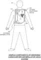
- FIG. 1is a conceptual diagram of a patient wearing a WCD, made according to embodiments.
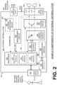
- FIG. 2is a diagram showing components of an external defibrillator, made according to embodiments.
- FIG. 3is a diagram of sample embodiments of components of an WCD system.
- FIG. 4is a conceptual diagram for illustrating how multiple electrodes of a WCD system may be used for sensing ECG signals along different vectors according to embodiments.
- FIG. 5is a conceptual flow diagram generally illustrating an AI process that may be implemented by various embodiments of the present disclosure.
- a wearable cardioverter defibrillator (WCD) systemmay protect an ambulatory patient by electrically restarting their heart if needed.
- WCDwearable cardioverter defibrillator
- Such a WCD systemmay have a number of components. These components can be provided separately as modules that can be interconnected, or can be combined with other components, and so on.
- FIG. 1depicts a patient 82 .
- Patient 82may also be referred to as a person and/or wearer, since the patient is wearing components of the WCD system.
- Patient 82is ambulatory, which means that, while wearing the wearable portion of the WCD system, patient 82 can walk around and is not necessarily bed-ridden.
- patient 82may be considered to be also a “user” of the WCD system, this is not a requirement.
- a user of the wearable cardioverter defibrillatormay also be a clinician such as a doctor, nurse, emergency medical technician (EMT) or other similarly tasked individual or group of individuals. In some cases, a user may even be a bystander.
- EMTemergency medical technician
- a WCD systemcan be configured to defibrillate the patient who is wearing the designated parts the WCD system. Defibrillating can be by the WCD system delivering an electrical charge to the patient's body in the form of an electric shock. The electric shock can be delivered in one or more pulses.
- FIG. 1also depicts components of a WCD system made according to embodiments.
- a support structure 170that is wearable by ambulatory patient 82 .
- support structure 170is configured to be worn by ambulatory patient 82 for at least several hours per day, and for at least several days, even a few months.
- support structure 170is shown only generically in FIG. 1 , and in fact partly conceptually.
- FIG. 1is provided merely to illustrate concepts about support structure 170 , and is not to be construed as limiting how support structure 170 is implemented, or how it is worn.
- Support structure 170can be implemented in many different ways. For example, it can be implemented in a single component or a combination of multiple components.
- support structure 170could include a vest, a half-vest, a garment, etc. In such embodiments such items can be worn similarly to analogous articles of clothing.
- support structure 170could include a harness, one or more belts or straps, etc. In such embodiments, such items can be worn by the patient around the torso, hips, over the shoulder, etc.
- support structure 170can include a container or housing, which can even be waterproof. In such embodiments, the support structure can be worn by being attached to the patient's body by adhesive material, for example as shown and described in U.S. Pat. No.
- Support structure 170can even be implemented as described for the support structure of US Pat. App. No. US2017/0056682, which is incorporated herein by reference.
- additional components of the WCD systemcan be in the housing of a support structure instead of being attached externally to the support structure, for example as described in the US2017/0056682 document. There can be other examples.
- FIG. 1shows a sample external defibrillator 100 .
- some aspects of external defibrillator 100include a housing and an energy storage module within the housing.
- defibrillator 100is sometimes called a main electronics module.
- the energy storage modulecan be configured to store an electrical charge.
- Other componentscan cause at least some of the stored electrical charge to be discharged via electrodes through the patient, so as to deliver one or more defibrillation shocks through the patient.
- FIG. 1also shows sample defibrillation electrodes 104 , 108 , which are coupled to external defibrillator 100 via electrode leads 105 .
- Defibrillation electrodes 104 , 108can be configured to be worn by patient 82 in a number of ways.
- defibrillator 100 and defibrillation electrodes 104 , 108can be coupled to support structure 170 , directly or indirectly.
- support structure 170can be configured to be worn by ambulatory patient 82 so as to maintain at least one of electrodes 104 , 108 on the body of ambulatory patient 82 , while patient 82 is moving around, etc.
- the electrodecan be thus maintained on the body by being attached to the skin of patient 82 , simply pressed against the skin directly or through garments, etc. In some embodiments the electrode is not necessarily pressed against the skin, but becomes biased that way upon sensing a condition that could merit intervention by the WCD system.
- many of the components of defibrillator 100can be considered coupled to support structure 170 directly, or indirectly via at least one of defibrillation electrodes 104 , 108 .
- defibrillator 100can administer, via electrodes 104 , 108 , a brief, strong electric pulse 111 through the body.
- Pulse 111is also known as shock, defibrillation shock, therapy, electrotherapy, therapy shock, etc. Pulse 111 is intended to go through and restart heart 85 , in an effort to save the life of patient 82 . Pulse 111 can further include one or more pacing pulses of lesser magnitude to simply pace heart 85 if needed, and so on.
- a prior art defibrillatortypically decides whether to defibrillate or not based on an ECG signal of the patient.
- external defibrillator 100may initiate defibrillation, or hold-off defibrillation, based on a variety of inputs, with the ECG signal merely being one of these inputs.
- a WCD systemcan obtain data from patient 82 .
- the WCD systemmay optionally include at least an outside monitoring device 180 .
- Device 180is called an “outside” device because it could be provided as a standalone device, for example not within the housing of defibrillator 100 .
- Device 180can be configured to sense or monitor at least one local parameter.
- a local parametercan be a parameter of patient 82 , or a parameter of the WCD system, or a parameter of the environment, as will be described later in this document.
- device 180may include one or more sensors or transducers. Each one of such sensors can be configured to sense a parameter of patient 82 , and to render an input responsive to the sensed parameter.
- the inputis quantitative, such as values of a sensed parameter; in other embodiments the input is qualitative, such as informing whether or not a threshold is crossed, and so on.
- these inputs about patient 82are also referred to herein as physiological inputs and patient inputs.
- a sensorcan be construed more broadly, as encompassing many individual sensors.
- device 180is physically coupled to support structure 170 .
- device 180may be communicatively coupled with other components that are coupled to support structure 170 .
- Such communicationcan be implemented by a communication module, as will be deemed applicable by a person skilled in the art in view of this description.
- one or more of the components of the shown WCD systemmay be customized for patient 82 .
- This customizationmay include a number of aspects.
- support structure 170can be fitted to the body of patient 82 .
- baseline physiological parameters of patient 82can be measured, such as the heart rate of patient 82 while resting, while walking, motion detector outputs while walking, etc.
- the measured values of such baseline physiological parameterscan be used to customize the WCD system, in order to make its diagnoses more accurate, since patients' bodies differ from one another.
- such parameter valuescan be stored in a memory of the WCD system, and so on.
- a programming interfacecan be made according to embodiments, which receives such measured values of baseline physiological parameters. Such a programming interface may input automatically in the WCD system these, along with other data.
- FIG. 2is a diagram showing components of an external defibrillator 200 , made according to embodiments. These components can be, for example, included in external defibrillator 100 of FIG. 1 .
- the components shown in FIG. 2can be provided in a housing 201 , which may also be referred to as casing 201 .
- External defibrillator 200is intended to be worn by a patient, such as ambulatory patient 82 of FIG. 1 .
- Defibrillator 200may further include a user interface 280 for a user 282 .
- User 282can be patient 82 , also known as wearer 82 .
- user 282can be a local rescuer at the scene, such as a bystander who might offer assistance, or a trained person.
- user 282might be a remotely located trained caregiver in communication with the WCD system.
- User interface 280can be made in a number of ways.
- User interface 280may include output devices, which can be visual, audible or tactile, for communicating to a user by outputting images, sounds or vibrations. Images, sounds, vibrations, and anything that can be perceived by user 282 can also be called human-perceptible indications (HPIs).
- output devicesThere are many examples of output devices.
- an output devicecan be a light, or a screen to display what is sensed, detected and/or measured, and provide visual feedback to rescuer 282 for their resuscitation attempts, and so on.
- Another output devicecan be a speaker, which can be configured to issue voice prompts, beeps, loud alarm sounds and/or words to warn bystanders, etc.
- User interface 280may further include input devices for receiving inputs from users. Such input devices may include various controls, such as pushbuttons, keyboards, touchscreens, one or more microphones, and so on.
- An input devicecan be a cancel switch, which is sometimes called an “I am alive” switch or “live man” switch. In some embodiments, actuating the cancel switch can prevent the impending delivery of a shock.
- Defibrillator 200may include an internal monitoring device 281 .
- Device 281is called an “internal” device because it is incorporated within housing 201 .
- Monitoring device 281can sense or monitor patient parameters such as patient physiological parameters, system parameters and/or environmental parameters, all of which can be called patient data.
- internal monitoring device 281can be complementary or an alternative to outside monitoring device 180 of FIG. 1 . Allocating which of the parameters are to be monitored by which of monitoring devices 180 , 281 can be done according to design considerations.
- Device 281may include one or more sensors, as also described elsewhere in this document. If internal monitoring device 281 is indeed provided, processor 230 may receive its inputs, etc.
- Patient parametersmay include patient physiological parameters.
- Patient physiological parametersmay include, for example and without limitation, those physiological parameters that can be of any help in detecting by the WCD system whether or not the patient is in need of a shock or other intervention or assistance.
- Patient physiological parametersmay also optionally include the patient's medical history, event history and so on. Examples of such parameters include the patient's ECG, blood oxygen level, blood flow, blood pressure, blood perfusion, pulsatile change in light transmission or reflection properties of perfused tissue, heart sounds, heart wall motion, breathing sounds and pulse.
- monitoring devices 180 , 281may include one or more sensors configured to acquire patient physiological signals.
- sensors or transducersinclude one or more electrodes to detect ECG data, a perfusion sensor, a pulse oximeter, a device for detecting blood flow (e.g. a Doppler device), a sensor for detecting blood pressure (e.g. a cuff), an optical sensor, illumination detectors and sensors perhaps working together with light sources for detecting color change in tissue, a motion sensor, a device that can detect heart wall movement, a sound sensor, a device with a microphone, an SpO2 sensor, and so on.
- sensorscan help detect the patient's pulse, and can therefore also be called pulse detection sensors, pulse sensors, and pulse rate sensors.
- a person skilled in the artmay implement other ways of performing pulse detection.
- the local parameteris a trend that can be detected in a monitored physiological parameter of patient 282 .
- a trendcan be detected by comparing values of parameters at different times over short and long terms.
- Parameters whose detected trends can particularly help a cardiac rehabilitation programinclude: a) cardiac function (e.g. ejection fraction, stroke volume, cardiac output, etc.); b) heart rate variability at rest or during exercise; c) heart rate profile during exercise and measurement of activity vigor, such as from the profile of an accelerometer signal and informed from adaptive rate pacemaker technology; d) heart rate trending; e) perfusion, such as from SpO2, CO2, or other parameters such as those mentioned above, f) respiratory function, respiratory rate, etc.; g) motion, level of activity; and so on.
- cardiac functione.g. ejection fraction, stroke volume, cardiac output, etc.
- c) heart rate profile during exercise and measurement of activity vigorsuch as from the profile of an accelerometer signal and informed
- Patient state parametersinclude recorded aspects of patient 282 , such as motion, posture, whether they have spoken recently plus maybe also what they said, and so on, plus optionally the history of these parameters.
- one of these monitoring devicescould include a location sensor such as a Global Positioning System (GPS) location sensor. Such a sensor can detect the location, plus a speed can be detected as a rate of change of location over time.
- GPSGlobal Positioning System
- Many motion detectorsoutput a motion signal that is indicative of the motion of the detector, and thus of the patient's body.
- Patient state parameterscan be very helpful in narrowing down the determination of whether SCA is indeed taking place.
- a WCD system made according to embodimentsmay thus include a motion detector.
- a motion detectorcan be implemented within monitoring device 180 or monitoring device 281 .
- Such a motion detectorcan be made in many ways as is known in the art, for example by using an accelerometer.
- a motion detector 287is implemented within monitoring device 281 .
- a motion detector of a WCD system according to embodimentscan be configured to detect a motion event.
- a motion eventcan be defined as is convenient, for example a change in motion from a baseline motion or rest, etc. In such cases, a sensed patient parameter is motion.
- System parameters of a WCD systemcan include system identification, battery status, system date and time, reports of self-testing, records of data entered, records of episodes and intervention, and so on.
- the motion detectormay render or generate, from the detected motion event or motion, a motion detection input that can be received by a subsequent device or functionality.
- Environmental parameterscan include ambient temperature and pressure. Moreover, a humidity sensor may provide information as to whether or not it is likely raining. Presumed patient location could also be considered an environmental parameter. The patient location could be presumed, if monitoring device 180 or 281 includes a GPS location sensor as per the above, and if it is presumed that the patient is wearing the WCD system.
- Defibrillator 200typically includes a defibrillation port 210 , which can be a socket in housing 201 .
- Defibrillation port 210includes electrical nodes 214 , 218 .
- Leads of defibrillation electrodes 204 , 208such as leads 105 of FIG. 1 , can be plugged into defibrillation port 210 , so as to make electrical contact with nodes 214 , 218 , respectively. It is also possible that defibrillation electrodes 204 , 208 are connected continuously to defibrillation port 210 , instead.
- defibrillation port 210can be used for guiding, via electrodes, to the wearer at least some of the electrical charge that has been stored in an energy storage module 250 that is described more fully later in this document.
- the electric chargewill be the shock for defibrillation, pacing, and so on.
- Defibrillator 200may optionally also have a sensor port 219 in housing 201 , which is also sometimes known as an ECG port.
- Sensor port 219can be adapted for plugging in sensing electrodes 209 , which are also known as ECG electrodes and ECG leads. It is also possible that sensing electrodes 209 can be connected continuously to sensor port 219 , instead.
- Sensing electrodes 209are types of transducers that can help sense an ECG signal, e.g. a 12-lead signal, or a signal from a different number of leads, especially if they make good electrical contact with the body of the patient and in particular with the skin of the patient.
- the support structurecan be configured to be worn by patient 282 so as to maintain sensing electrodes 209 on a body of patient 282 .
- sensing electrodes 209can be attached to the inside of support structure 170 for making good electrical contact with the patient, similarly with defibrillation electrodes 204 , 208 .
- a WCD systemalso includes a fluid that it can deploy automatically between the electrodes and the patient's skin.
- the fluidcan be conductive, such as by including an electrolyte, for establishing a better electrical contact between the electrodes and the skin. Electrically speaking, when the fluid is deployed, the electrical impedance between each electrode and the skin is reduced. Mechanically speaking, the fluid may be in the form of a low-viscosity gel, so that it does not flow away, after being deployed, from the location it is released near the electrode.
- the fluidcan be used for both defibrillation electrodes 204 , 208 , and for sensing electrodes 209 .
- a WCD systemaccording to embodiments further includes a fluid deploying mechanism 274 .
- Fluid deploying mechanism 274can be configured to cause at least some of the fluid to be released from the reservoir and be deployed near one or both of the patient locations to which electrodes 204 , 208 are configured to be attached to the patient.
- fluid deploying mechanism 274is activated prior to the electrical discharge responsive to receiving activation signal AS from a processor 230 , which is described more fully later in this document.
- defibrillator 200also includes a measurement circuit 220 , as one or more of its working together with its sensors or transducers. Measurement circuit 220 senses one or more electrical physiological signals of the patient from sensor port 219 , if provided. Even if defibrillator 200 lacks sensor port 219 , measurement circuit 220 may optionally obtain physiological signals through nodes 214 , 218 instead, when defibrillation electrodes 204 , 208 are attached to the patient. In these cases, the input reflects an ECG measurement.
- the patient parametercan be an ECG, which can be sensed as a voltage difference between electrodes 204 , 208 .
- the patient parametercan be an impedance, which can be sensed between electrodes 204 , 208 and/or between the connections of sensor port 219 considered pairwise. Sensing the impedance can be useful for detecting, among other things, whether these electrodes 204 , 208 and/or sensing electrodes 209 are not making good electrical contact with the patient's body. These patient physiological signals may be sensed when available. Measurement circuit 220 can then render or generate information about them as inputs, data, other signals, etc. As such, measurement circuit 220 can be configured to render a patient input responsive to a patient parameter sensed by a sensor.
- measurement circuit 220can be configured to render a patient input, such as values of an ECG signal, responsive to the ECG signal sensed by sensing electrodes 209 . More strictly speaking, the information rendered by measurement circuit 220 is output from it, but this information can be called an input because it is received as an input by a subsequent device or functionality.
- Defibrillator 200also includes a processor 230 .
- Processor 230may be implemented in a number of ways in various embodiments. Such ways include, by way of example and not of limitation, digital and/or analog processors such as microprocessors and Digital Signal Processors (DSPs), controllers such as microcontrollers, software running in a machine, programmable circuits such as Field Programmable Gate Arrays (FPGAs), Field-Programmable Analog Arrays (FPAAs), Programmable Logic Devices (PLDs), Application Specific Integrated Circuits (ASICs), any combination of one or more of these, and so on.
- DSPsDigital Signal Processors
- FPGAsField Programmable Gate Arrays
- FPAAsField-Programmable Analog Arrays
- PLDsProgrammable Logic Devices
- ASICsApplication Specific Integrated Circuits
- Processor 230may include, or have access to, a non-transitory storage medium, such as memory 238 that is described more fully later in this document.
- a memorycan have a non-volatile component for storage of machine-readable and machine-executable instructions.
- a set of such instructionscan also be called a program.
- the instructionswhich may also be referred to as “software,” generally provide functionality by performing acts, operations and/or methods as may be disclosed herein or understood by one skilled in the art in view of the disclosed embodiments.
- instances of the softwaremay be referred to as a “module” and by other similar terms.
- a moduleincludes a set of executable instructions so as to offer or fulfill a particular functionality. Embodiments of modules and the functionality delivered are not limited by the embodiments described in this document.
- Detection module 232can include a Ventricular Fibrillation (VF) detector.
- VFVentricular Fibrillation
- the patient's sensed ECG from measurement circuit 220which can be available as inputs, data that reflect values, or values of other signals, may be used by the VF detector to determine whether the patient is experiencing VF. Detecting VF is useful, because VF typically results in SCA.
- Detection module 232can also include a Ventricular Tachycardia (VT) detector, and so on.
- VTVentricular Tachycardia
- Another such module in processor 230can be an advice module 234 , which generates advice for what to do.
- the advicecan be based on outputs of detection module 232 .
- the adviceis a shock/no shock determination that processor 230 can make, for example via advice module 234 .
- the shock/no shock determinationcan be made by executing a stored Shock Advisory Algorithm.
- a Shock Advisory Algorithmcan make a shock/no shock determination from one or more ECG signals that are captured according to embodiments and determine whether or not a shock criterion is met. The determination can be made from a rhythm analysis of the captured ECG signal or otherwise.
- an electrical chargeis delivered to the patient.
- Delivering the electrical chargeis also known as discharging and shocking the patient. As mentioned above, such can be for defibrillation, pacing, and so on.
- Processor 230can include additional modules, such as other module 236 , for other functions.
- other module 236may include functional instructions for performing machine learning or artificial intelligence functions. Examples of such functional instructions may be implemented as a neural network, random forest, a support vector machine, recursive partitioning, Bayesian methods, fuzzy rule-based systems, or the like.
- One or more of such other modules 236may be configured to implement various embodiments of artificial intelligence functions described below.
- Defibrillator 200optionally further includes a memory 238 , which can work together with processor 230 .
- Memory 238may be implemented in a number of ways. Such ways include, by way of example and not of limitation, volatile memories, Nonvolatile Memories (NVM), Read-Only Memories (ROM), Random Access Memories (RAM), magnetic disk storage media, optical storage media, smart cards, flash memory devices, any combination of these, and so on.
- Memory 238is thus a non-transitory storage medium.
- Memory 238if provided, can include programs for processor 230 , which processor 230 may be able to read and execute. More particularly, the programs can include sets of instructions in the form of code, which processor 230 may be able to execute upon reading.
- the programsmay also include other information such as configuration data, profiles, scheduling etc. that can be acted on by the instructions. Executing is performed by physical manipulations of physical quantities, and may result in functions, operations, processes, acts, actions and/or methods to be performed, and/or the processor to cause other devices or components or blocks to perform such functions, operations, processes, acts, actions and/or methods.
- the programscan be operational for the inherent needs of processor 230 , and can also include protocols and ways that decisions can be made by advice module 234 .
- memory 238can store prompts for user 282 , if this user is a local rescuer.
- memory 238can store data. This data can include patient data, system data and environmental data, for example as learned by internal monitoring device 281 and outside monitoring device 180 . The data can be stored in memory 238 before it is transmitted out of defibrillator 200 , or be stored there after it is received by defibrillator 200 .
- Defibrillator 200can optionally include a communication module 290 , for establishing one or more wired or wireless communication links with other devices of other entities, such as a remote assistance center, Emergency Medical Services (EMS), and so on.
- the communication linkscan be used to transfer data and commands.
- the datamay be patient data, event information, therapy attempted, CPR performance, system data, environmental data, and so on.
- communication module 290may transmit wirelessly, e.g. on a daily basis, heart rate, respiratory rate, and other vital signs data to a server accessible over the internet, for instance as described in US 20140043149. This data can be analyzed directly by the patient's physician and can also be analyzed automatically by algorithms designed to detect a developing illness and then notify medical personnel via text, email, phone, etc.
- Module 290may also include such interconnected sub-components as may be deemed necessary by a person skilled in the art, for example an antenna, portions of a processor, supporting electronics, outlet for a telephone or a network cable, etc.
- Defibrillator 200may also include a power source 240 .
- power source 240typically includes a battery. Such a battery is typically implemented as a battery pack, which can be rechargeable or not. Sometimes a combination is used of rechargeable and non-rechargeable battery packs.
- Other embodiments of power source 240can include an AC power override, for where AC power will be available, an energy-storing capacitor, and so on. Appropriate components may be included to provide for charging or replacing power source 240 .
- power source 240is controlled and/or monitored by processor 230 .
- Defibrillator 200may additionally include an energy storage module 250 .
- Energy storage module 250can be coupled to the support structure of the WCD system, for example either directly or via the electrodes and their leads. Module 250 is where some electrical energy can be stored temporarily in the form of an electrical charge, when preparing it for discharge to administer a shock. In embodiments, module 250 can be charged from power source 240 to the desired amount of energy, as controlled by processor 230 .
- module 250includes a capacitor 252 , which can be a single capacitor or a system of capacitors, and so on.
- energy storage module 250includes a device that exhibits high power density, such as an ultracapacitor. As described above, capacitor 252 can store the energy in the form of an electrical charge, for delivering to the patient.
- a decision to shockcan be made responsive to the shock criterion being met, as per the above-mentioned determination.
- processor 230can be configured to cause at least some or all of the electrical charge stored in module 250 to be discharged through the body of patient 82 while the support structure is being worn by patient 82 , so as to deliver a therapy shock 111 to patient 82 .
- defibrillator 200moreover includes a discharge circuit 255 .
- processor 230can be configured to control discharge circuit 255 to discharge through the patient at least some of all of the electrical charge stored in energy storage module 250 . Discharging can be to nodes 214 , 218 , and from there to defibrillation electrodes 204 , 208 , so as to cause a shock to be delivered to the patient.
- Circuit 255can include one or more switches 257 . Switches 257 can be made in a number of ways, such as by an H-bridge, and so on. Circuit 255 could also be thus controlled via processor 230 , and/or user interface 280 .
- a time waveform of the dischargemay be controlled by thus controlling discharge circuit 255 .
- the amount of energy of the dischargecan be controlled by how much energy storage module has been charged, and also by how long discharge circuit 255 is controlled to remain open.
- Defibrillator 200can optionally include other components.
- FIG. 3is a diagram of sample embodiments of components of an WCD system.
- a support structure 370includes a vest-like wearable garment.
- Support structure 370has a back side 371 , and a front side 372 that closes in front of the chest of the patient.
- the WCD system of FIG. 3also includes an external defibrillator 300 .
- FIG. 3does not show any support for external defibrillator 300 , which may be carried in a purse, on a belt, by a strap over the shoulder, and so on.
- Wires 305connect external defibrillator 300 to electrodes 304 , 308 , 309 .
- electrodes 304 , 308are defibrillation electrodes
- electrodes 309are ECG sensing electrodes.
- Support structure 370is configured to be worn by the ambulatory patient so as to maintain electrodes 304 , 308 , 309 on a body of the patient. Indeed, back defibrillation electrodes 308 are maintained in pockets 378 . Of course, the inside of pockets 378 can be made with loose netting, so that electrodes 308 can contact the back of the patient, especially with the help of the conductive fluid that has been deployed. In addition, sensing electrodes 309 are maintained in positions that surround the patient's torso, for sensing ECG signals and/or the impedance of the patient.
- ECG signals in a WCD systemmay include too much electrical noise to be useful.
- multiple ECG sensing electrodes 309are provided, for presenting many options to processor 230 . These options are different vectors for sensing the ECG signal, as described now in more detail.
- FIG. 4is a conceptual diagram for illustrating how multiple electrodes of a WCD system may be used for sensing ECG signals along different vectors according to embodiments.
- a section of a patient 482 having a heart 485is shown.
- patient 482is viewed from the top, patient 482 is facing downwards, and the plane of FIG. 4 intersects patient 482 at the torso of the patient.
- Electrodes 491 , 492 , 493 , 494are maintained on the torso of patient 482 , and have respective wire leads 461 , 462 , 463 , 464 . It will be recognized that electrodes 491 , 492 , 493 , 494 surround the torso, similarly with sensing electrodes 309 in the example of FIG. 3 .
- Electrodes 491 , 492 , 493 , 494define a vector, along which an ECG signal may be sensed and/or measured.
- electrodes 491 , 492 , 493 , 494define six vectors 471 , 472 , 473 , 474 , 475 , 476 .
- FIG. 4thus illustrates a multi-vector embodiment.
- ECG signals 401 , 402 , 403 , 404 , 405 , 406may thus be sensed and/or measured from channels A, B, C, D, E, F, respectively, and in particular from the appropriate pairings of wire leads 461 , 462 , 463 , 464 for each channel.
- electrodes 491 , 492 , 493 , 494are drawn as being on the same plane for simplicity and as is preferred, while that is not necessarily the case. Accordingly, vectors 471 , 472 , 473 , 474 , 475 , 476 are not necessarily on the same plane, either.
- a WCDmay assess which of ECG signals 401 , 402 , 403 , 404 , 405 , 406 is best for rhythm analysis and interpretation. For example, ECG signals that have the most noise may be ignored, discarded, not considered, while leaving the remaining ECG signals as candidates for making the shock/no shock determination.
- the vectorsmay be aggregated to make a shock/no shock decision, and/or to determine the patient's heart rate and/or QRS widths.
- the aggregationcan be implemented as disclosed in U.S. Pat. No. 9,757,581 issued Sep. 12, 2017 entitled “WEARABLE CARDIOVERTER DEFIBRILLATOR COMPONENTS MAKING AGGREGATE SHOCK/NO SHOCK DETERMINATION FROM TWO OR MORE ECG SIGNALS”, which is incorporated herein by reference.
- FIG. 5is a conceptual flow diagram generally illustrating an AI process 500 that may be implemented by various embodiments of the present disclosure.
- various embodimentsmay implement artificial intelligence and/or machine learning to automate and accomplish various functions of a WCD which have been heretofore impractical. Specific, non-exhaustive examples of such embodiments are provided below for completeness. These and other embodiments will be apparent to those skilled in the art upon a detailed review of this discussion.
- an AI processing module 502receives input from various sources, such as data from various WCD sensors 504 described above, and/or other sources 506 .
- the information received from the WCD sensors 504may take the form of environmental information (e.g., motion, temperature, humidity, or any of the other non-patient information described above) as well as patient information (e.g., heart rate, ECG, blood pressure, pulse oximetry, or any of the other patient-related information described above).
- the AI processing module 502may receive additional information from, for example, a user interface 508 or other input mechanism (e.g., communication link to a remote data source). Examples of such additional information may take the form of instructions or data provided by a user, either a local user or a remote user, that the AI processing module 502 may use for artificial processing and machine learning.
- additional informationmay take the form of instructions or data provided by a user, either a local user or a remote user, that the AI processing module 502 may use for artificial processing and machine learning.
- the AI processing module 502performs artificial intelligence and machine learning operations to improve, predict, and/or control operations to be performed by or on the WCD.
- the operations performed by the AI processing module 502may take any form, such as making determinations regarding whether to deliver therapy to a patient, improve characteristics about the WCD (e.g., for comfort or operation), better detect the operating and maintenance state of the WCD, implement instructions provided by remote users, collect and learn data about the use of the WCD or the patient, and many more.
- adjustments 512may be made to the WCD to improve the operation of the WCD, the patient's wellbeing, or to other functionality provided by the WCD. Again, as described in greater detail below, many various features and functions of the WCD may benefit from the processing by the AI processing module 502 . As those adjustments are made, the process 500 may return to the data input portion of the process 500 . In this manner, the AI processing module 502 is constantly receiving input data, making adjustments to the WCD or the WCD system, and further refining additional adjustments. Still further, training data 510 may be used by the AI processing module 502 either to initially train the AI processing module 502 prior to use, or to improve the efficiency, accuracy, and operation of the AI processing module 502 .
- AIartificial intelligence
- the Garmenta WCD or other patient worn medical device
- the data from patients wearing the Garmentcan be collected and processed using AI technology (e.g., machine learning algorithms) to improve the fit of the garment to reduce noise in sensor output signals, loss of sensor contact with the patient, comfort (as indicated by patient feedback), compliance, etc.
- AI technologye.g., machine learning algorithms
- the dataincludes sensor data from the sensors coupled to or integrated with the Garment, as well as other data from other sources.
- the sensor datacomprises one or more of the following: ECG, heart rate, blood pressure, patient movement, patient posture, patient's body temperature, oximetry, capnography, ambient temperature, ambient humidity, perspiration (e.g., moisture, pH, particular chemicals), atmospheric pressure, patient's vocalizations/breathing sounds (e.g., the properties of the patient's voice, snoring, breathing, sighing, coughing, etc.), or other sensor data.
- the dataalso comprises one or more of the patients' size, shape (e.g., by optically scanning the patient's body using a 3D body scanner such as described at https://www.aniwaa.com/best-3d-body-scanners; or an app similar to the MTailer app that uses a smartphone camera), weight, BMI, muscle mass, body fat percentage, average water weight, age, gender, fitness level, average activity level, patient's usual activities, the time of day, etc. that are not necessarily collected by garment sensors.
- at least some of this other datais received by the Garment via a user entering the data via a user interface.
- the AI technologycomprises a multi-layer neural network (example, a convolutional neural network) configured with one or more machine learning algorithms to correlate the patient data to garment parameters that best fit a particular patient.
- AdaBoostor a support vector machine (SVM) are used.
- the AI technologyis implemented using one or more processors of the Garment, while in other embodiments, the AI technology is implemented at least in part using a cloud-based system accessible (e.g., wirelessly) by the Garment. These embodiments of the AI technology can also be used in the other embodiments described herein.
- this “non-garment” datais collected and processed by the AI technology to determine the style/dimensions/materials/features/components of a Garment that best fits the patient, and the best locations for the sensors and other components of the medical device.
- the Garmentcan be custom fabricated to these dimension and sensor locations, or selected from a group of different standard sizes/configurations, or the Garment may be made with adjustable dimensions and sensor/component locations via straps, belts, laces, zippers, Velcro, removable/replaceable panels/sections/components, or a combination of standard sizes with adjustable components, etc.
- the sensor data and patient feedbackis collected and processed using the AI technology to determine if the Garment dimensions and/or sensor/component placement should be adjusted. For example, if the data such as activity level, breathing sounds, snoring sounds, etc. indicate that the Garment dimensions are too tight and are restricting the patient's ability to take breath during certain activities and/or postures (e.g., walking, sleeping, sitting), the AI technology can detect these conditions and provide notifications or prompts with instructions or suggestions for adjusting the fit of the garment.
- the AI technologycan detect these conditions and provide notifications or prompts with instructions or suggestions for adjusting the fit of the garment.
- AIartificial intelligence
- the data from patients wearing the Garmentcan be collected and processed using AI technology (e.g., machine learning algorithms), along with the diagnosis and treatment data corresponding to the patient data to determine whether the patient is experiencing a condition that needs a treatment.
- AI technologye.g., machine learning algorithms
- These conditions/treatmentsinclude cardiac conditions that can be treated by a WCD, as well as other non-cardiac conditions/treatments, such as stroke, apnea, dizziness, coughing, seizures, etc.
- the dataincludes sensor data from the sensors coupled to the garment, as well as other data as described above for the Garment Fitting Embodiments.
- Embodiments of the AI technologyare also described above in conjunction with the Garment Fitting Embodiments.
- Other embodiments of the AI technologycan include using stochastic computing circuits (e.g., as disclosed in https://techxplore.com/news/2018-10-method-automate-synthesis-stochastic-circuits.html) to implement neural networks (e.g., as disclosed in https://ieeexplore.ieee.org/document/8119196).
- Some embodiments of these stochastic computing circuit-based machine learning implementationshave reduced size and power requirements compared to “binary” neural networks while still having similar performance, which can be advantageous in battery powered wearable medical devices such as WCDs and particularly in adhesive systems such as being developed by Element Science.
- These embodiments of the AI technologycan also be used in the other embodiments described herein.
- the data from sensor(s) of the garmentis received and processed by the AI technology to identify a condition.
- the Garmentcan automatically provide a treatment for the condition, or a notification or prompt to the user or bystanders (e.g., visual via a display, or an audible message via a speaker) or remote recipients (e.g., via a communication channel such as cellular, Wi-Fi, Bluetooth, etc.).
- bystanderse.g., visual via a display, or an audible message via a speaker
- remote recipientse.g., via a communication channel such as cellular, Wi-Fi, Bluetooth, etc.
- some embodimentsare configured to detect whether a patient is unsteady or dizzy and likely to fall and provide a notification to the user to take appropriate safety action (e.g., to sit down or find a support).
- Another exampleis an embodiment that is configured to detect if a patient is experiencing apnea and provide a notification to the user or remote clinician so that the user can be prescribed a CPAP machine or other treatment.
- the AI technologyis configured to process data such as posture, heart rate, patient's voice properties (e.g., pitch, tone, rate, slurring), etc. to detect if the patient is experiencing a stroke.
- AIartificial intelligence
- the data from sensors of the Garment generated by previous deployments of the Garments along with corresponding error/failure/maintenance datacan be processed using AI technology to develop an AI algorithm that can predict an imminent failure of the Garment (or a component thereof).
- imminent failure of an electrode connectormay be associated with certain patterns of ECG noise, patient movement, cumulative wear-time, cumulative connect/disconnect cycles, ambient temperature, ambient humidity, drop detection, impedance changes, etc.
- the AI technologycan determine, and then use to issue prompts for connector inspection/maintenance.
- Other examples of “failures” that are detectable by embodiments of the present disclosureinclude failure of wiring/cabling between sensors and other electronics of the medical device, the battery, displays (e.g., LCD displays), touchscreens, buttons/switches, etc.
- the datacan include vibration sensor data, rotational speed data, temperature data, etc. sensed at the component that can be processed using the AI technology to predict failures and provide prompts to take appropriate maintenance action.
- the AI technologyis implemented using the previously described stochastic computing circuits to reduce the size and power requirements of the wearable medical device.
- AI technologyis used to capture and store data from the patient and wearable medical device, present it to the patient's doctor/clinician, and use AI technology to monitor the actions taken by the doctor/clinician in response to the data to customize the presentation of future data to that doctor/clinician.
- AIartificial intelligence
- a large amount of data from various patient physiological parameter sensorse.g., one or more of heart rate, ECG, impedance, accelerometer, body temperature, blood pressure, oximetry, etc.
- other parameterse.g., ambient temperature, time of day, wear-time, activity level, etc.
- the AI technologyis configured to monitor the doctor/clinician's actions/responses in accessing this data and based on these actions, generate a “default” presentation of the data for this particular doctor/clinician. For example, if a doctor consistently views the patient's activity level, wear-time, heart rate and ECG data while ignoring the other data, the AI technology learns to present only the wear-time, heart rate and ECG data in a “home page” whenever the doctor/clinician accesses the patient's data.
- the AI technologycan also be configured to learn the doctor's response to certain conditions in the “home page” data and automatically provide appropriate additional data.
- the “home page”may include the patient's heart rate data but not activity level and QRS width data. However, when the heart rate is higher than a certain threshold, this example doctor/clinician tends to access the data for activity level and QRS width).
- the AI technologyanalyzes the data, learns the “conditions” for which the doctor/clinicians accesses additional data, and then automatically presents the additional data when the conditions are detected.
- the AI technologylearns the heart rate threshold that causes the doctor/clinician to access the activity level and QRS width data, and when the heart rate is above this threshold when the doctor/clinician accesses the “home page”, the AI technology also presents the activity level and QRS width data. These embodiments can improve the efficiency of the doctor/clinician in monitoring and diagnosing the patient's condition.
- AI technologyis used to capture and store data related to responses of users (e.g., the patient and/or a remote person such as a family member or doctor/clinician monitoring the patient via a communication network) to notifications, alerts, alarms, prompts, etc. (also referred to as User Notifications) and based on these responses use the AI technology to customize the presentation of future User Notifications presented to each user.
- userse.g., the patient and/or a remote person such as a family member or doctor/clinician monitoring the patient via a communication network
- notifications, alerts, alarms, prompts, etc.also referred to as User Notifications
- the input data for the AI technologyincludes:
- the AI technologyis configured to monitor this data and based on these actions, learn the Users' responses to the various User Notifications and customize the User Notifications for each user to achieve the best user response under the current conditions. For example, the AI technology can learn that at night while sleeping, a particular patient does not respond quickly to audio User Notifications but will respond quickly to flashing light User Notifications and configure the medical device to issue flashing light User Notifications when needed while the patient is sleeping at night. In another example, the AI technology can learn that while exercising a particular patient does not detect or responds slowly to audio and visual User Notifications but does respond quickly to both low power and high power intermittent vibration User Notifications. The AI technology can configure the medical device to issue low power level vibrations when needed while the patient is exercising, which can also advantageously save power while still achieving a fast response time from the patient.
- the above data from previous patientsis processed using AI technology to determine default sets of User Notifications for categories of patients and users.
- the category that the patient most closely matchesis determined and the Garment is initially configured with the User Notifications for that category.
- the AI technology for that Garmentthen operates as described above to customize the User Notifications for that patient and other users associated with that Garment. For example, in some embodiments the AI technology is used to identify User Notifications that work best for improving patient compliance.
- the patient compliance User Notifications(e.g., periodic reminders, prompts when non-compliance is detected, substantially simultaneous or concurrent notifications to family members and/or the patient's doctor) issued to previous patients and how quickly and well the patient responded to these compliance User Notifications is collected and processed by AI technology to determine default sets of patient compliance User Notifications for categories of patients and associated users.
- AI technologyis used in conjunction with one or more tests provided to the patient.
- the patient's responses to the test(s) along with other dataare processed using AI technology to detect or assess the patient's present condition and/or need for treatment.
- the testsinclude one or more of: a grip test; a manual dexterity test; a balance test; a following instructions test; tests to determine whether the patient can perceive the various types of User Notifications that the Garment can provide to the patient, etc.
- the AI technologyprocesses data associated with these tests from previous patients that used the Garment (and the current patients' previous test responses in some embodiments) to identify the patient's current condition and whether a treatment, notification or further testing is appropriate for the patient.
- the Garment's AI technologycan be configured to receive and process the test results and other data (e.g., the patient gender, age, weight, health history, time of day, ambient temperature, etc.) to assess the patient's cardiac condition.
- the Garmentcan use the assessment to take appropriate actions such as providing notifications to the patient or a remote user (e.g., the patient's doctor).
- Balance and mobility testscan be used to assess the patients risk of falling and provide appropriate action and to assess whether a patient's fall is due to the patient becoming unconscious vs be conscious and falling due to being unbalanced.
- the AI technologycan use the testing data and other patient data as part of a patient recovery or rehabilitation program, to prompt, encourage and/or instruct the patient on the appropriate exercises/activities and the amount of exertion or energy the patient should use in these exercises/activities that aid the patient's progress in the recovery/rehabilitation program.
- AI technologyis used to recognize the patient's voice for implementing voice recognition, activation and control of the Garment.
- the Garment's AI technologyis configured to enable the Garment to listen via a microphone for voice commands to appropriately respond to questions from patients and their medical advisors (vs questions from bystanders) to assist the patient while protecting the patients' privacy.
- the Garment's AI technologyis configured to also “listen” to other audio data to provide context for the voice commands to provide more accurate/appropriate responses to the voice commands. For example, the patient may use a voice command to ask for assistance because the patient is not feeling well.
- the Garmentcan be configured to emit requests to bystanders to call 911. But if the audio data indicates the patient is at home alone, the Garment can be configured to transmit the request to family members via a wireless communication link.
Landscapes
- Health & Medical Sciences (AREA)
- Engineering & Computer Science (AREA)
- Cardiology (AREA)
- Public Health (AREA)
- Artificial Intelligence (AREA)
- Nuclear Medicine, Radiotherapy & Molecular Imaging (AREA)
- Radiology & Medical Imaging (AREA)
- Life Sciences & Earth Sciences (AREA)
- Animal Behavior & Ethology (AREA)
- General Health & Medical Sciences (AREA)
- Heart & Thoracic Surgery (AREA)
- Veterinary Medicine (AREA)
- Biomedical Technology (AREA)
- Computer Vision & Pattern Recognition (AREA)
- Evolutionary Computation (AREA)
- Medical Informatics (AREA)
- Software Systems (AREA)
- Physics & Mathematics (AREA)
- General Physics & Mathematics (AREA)
- Automation & Control Theory (AREA)
- Electrotherapy Devices (AREA)
Abstract
Description
- 1. the event or patient condition for which the User Notification is issued (e.g., sensor detachment, battery low, imminent therapy delivery, not wearing Garment, stop moving to reduce sensor noise, prompt to take medication, prompt to exercise, prompt to rest, prompt to contact doctor/clinician, etc.)
- 2. the user's action (or inaction) taken in response to the User Notification (e.g., ignoring the User Notification, disabling the User Notification without taking the appropriate responsive action, performing the appropriate responsive action after disabling the User Notification, performing the appropriate responsive action before disabling the User Notification, contacting a doctor or a family member after a User Notification, user feedback such as, for example via a “like” or “dislike” button on the UI.)
- 3. the user's response time to the User Notification,
- 4. the time of day the User Notification was provided,
- 5. the patient's activity and/or posture when the User Notification was provided (e.g., exercising, sleeping, laying down, sitting, traveling in a vehicle, etc.)
- 6. the type of User Notification, which can include one or more of:
- a. audio (such as voice prompt, tones, beeps, combinations thereof, etc.)
- b. visual (such as flashing or continuous lights, textual, graphical, combinations thereof),
- c. physical (such as intermittent or continuous vibration, haptic, gyroscopic, small electric shocks, etc.).
Claims (12)
Priority Applications (2)
| Application Number | Priority Date | Filing Date | Title |
|---|---|---|---|
| US16/946,512US11672996B2 (en) | 2019-06-24 | 2020-06-24 | Wearable cardioverter defibrillator with AI-based features |
| US18/309,958US20230264033A1 (en) | 2019-06-24 | 2023-05-01 | Wearable cardioverter defibrillator with ai-based features |
Applications Claiming Priority (2)
| Application Number | Priority Date | Filing Date | Title |
|---|---|---|---|
| US201962865693P | 2019-06-24 | 2019-06-24 | |
| US16/946,512US11672996B2 (en) | 2019-06-24 | 2020-06-24 | Wearable cardioverter defibrillator with AI-based features |
Related Child Applications (1)
| Application Number | Title | Priority Date | Filing Date |
|---|---|---|---|
| US18/309,958ContinuationUS20230264033A1 (en) | 2019-06-24 | 2023-05-01 | Wearable cardioverter defibrillator with ai-based features |
Publications (2)
| Publication Number | Publication Date |
|---|---|
| US20200398065A1 US20200398065A1 (en) | 2020-12-24 |
| US11672996B2true US11672996B2 (en) | 2023-06-13 |
Family
ID=74039032
Family Applications (2)
| Application Number | Title | Priority Date | Filing Date |
|---|---|---|---|
| US16/946,512Active2040-12-04US11672996B2 (en) | 2019-06-24 | 2020-06-24 | Wearable cardioverter defibrillator with AI-based features |
| US18/309,958PendingUS20230264033A1 (en) | 2019-06-24 | 2023-05-01 | Wearable cardioverter defibrillator with ai-based features |
Family Applications After (1)
| Application Number | Title | Priority Date | Filing Date |
|---|---|---|---|
| US18/309,958PendingUS20230264033A1 (en) | 2019-06-24 | 2023-05-01 | Wearable cardioverter defibrillator with ai-based features |
Country Status (1)
| Country | Link |
|---|---|
| US (2) | US11672996B2 (en) |
Cited By (1)
| Publication number | Priority date | Publication date | Assignee | Title |
|---|---|---|---|---|
| US20230264033A1 (en)* | 2019-06-24 | 2023-08-24 | West Affum Holdings Dac | Wearable cardioverter defibrillator with ai-based features |
Families Citing this family (5)
| Publication number | Priority date | Publication date | Assignee | Title |
|---|---|---|---|---|
| WO2020111218A1 (en)* | 2018-11-30 | 2020-06-04 | 東レ株式会社 | Inspection assisting method and inspection assisting system |
| EP4188766A1 (en)* | 2020-07-27 | 2023-06-07 | TVS Motor Company Limited | Alert detection system |
| US12409331B2 (en) | 2021-02-12 | 2025-09-09 | West Affum Holdings Dac | Wearable Cardioverter Defibrillator (WCD) with artificial intelligence features |
| JP2023117429A (en)* | 2022-02-11 | 2023-08-24 | ウェスト・アファム・ホールディングス・ディーエーシー | Wearable Automatic Defibrillator (WCD) with Artificial Intelligence |
| US20240139531A1 (en)* | 2022-10-28 | 2024-05-02 | West Affum Holdings Dac | Wcd pacing pulse generation |
Citations (89)
| Publication number | Priority date | Publication date | Assignee | Title |
|---|---|---|---|---|
| US3724355A (en) | 1970-06-12 | 1973-04-03 | K Schranz | Apparatus for processing exposed photographic film or the like |
| US4583524A (en) | 1984-11-21 | 1986-04-22 | Hutchins Donald C | Cardiopulmonary resuscitation prompting |
| US4619265A (en) | 1984-03-08 | 1986-10-28 | Physio-Control Corporation | Interactive portable defibrillator including ECG detection circuit |
| US4928690A (en) | 1988-04-25 | 1990-05-29 | Lifecor, Inc. | Portable device for sensing cardiac function and automatically delivering electrical therapy |
| US4955381A (en) | 1988-08-26 | 1990-09-11 | Cardiotronics, Inc. | Multi-pad, multi-function electrode |
| US5078134A (en) | 1988-04-25 | 1992-01-07 | Lifecor, Inc. | Portable device for sensing cardiac function and automatically delivering electrical therapy |
| US5228449A (en) | 1991-01-22 | 1993-07-20 | Athanasios G. Christ | System and method for detecting out-of-hospital cardiac emergencies and summoning emergency assistance |
| US5353793A (en) | 1991-11-25 | 1994-10-11 | Oishi-Kogyo Company | Sensor apparatus |
| US5394892A (en) | 1990-04-02 | 1995-03-07 | K J Mellet Nominees Pty Ltd | CPR prompting apparatus |
| US5405362A (en) | 1991-04-29 | 1995-04-11 | The Board Of Regents For The University Of Texas System | Interactive external defibrillation and drug injection system |
| US5474574A (en) | 1992-06-24 | 1995-12-12 | Cardiac Science, Inc. | Automatic external cardioverter/defibrillator |
| US5662690A (en) | 1994-12-08 | 1997-09-02 | Heartstream, Inc. | Defibrillator with training features and pause actuator |
| US5782878A (en) | 1994-12-07 | 1998-07-21 | Heartstream, Inc. | External defibrillator with communications network link |
| US5792204A (en) | 1996-05-08 | 1998-08-11 | Pacesetter, Inc. | Methods and apparatus for controlling an implantable device programmer using voice commands |
| WO1998039061A2 (en) | 1997-03-07 | 1998-09-11 | Cadent Medical Corporation | Wearable defibrillation system |
| US5902249A (en) | 1995-03-03 | 1999-05-11 | Heartstream, Inc. | Method and apparatus for detecting artifacts using common-mode signals in differential signal detectors |
| US5913685A (en) | 1996-06-24 | 1999-06-22 | Hutchins; Donald C. | CPR computer aiding |
| US6047203A (en) | 1997-03-17 | 2000-04-04 | Nims, Inc. | Physiologic signs feedback system |
| US6065154A (en) | 1998-04-07 | 2000-05-23 | Lifecor, Inc. | Support garments for patient-worn energy delivery apparatus |
| US6108197A (en) | 1992-05-15 | 2000-08-22 | Via, Inc. | Flexible wearable computer |
| US6201992B1 (en) | 1999-04-01 | 2001-03-13 | Agilent Technologies, Inc. | Defibrillator interface capable of generating video images |
| US6263238B1 (en) | 1998-04-16 | 2001-07-17 | Survivalink Corporation | Automatic external defibrillator having a ventricular fibrillation detector |
| US6287328B1 (en) | 1999-04-08 | 2001-09-11 | Agilent Technologies, Inc. | Multivariable artifact assessment |
| US6319011B1 (en) | 1995-04-06 | 2001-11-20 | Michael J. Motti | Automatic training defibrillator simulator and method |
| US6334070B1 (en) | 1998-11-20 | 2001-12-25 | Medtronic Physio-Control Manufacturing Corp. | Visual and aural user interface for an automated external defibrillator |
| US6356785B1 (en) | 1997-11-06 | 2002-03-12 | Cecily Anne Snyder | External defibrillator with CPR prompts and ACLS prompts and methods of use |
| US6437083B1 (en) | 2001-12-06 | 2002-08-20 | General Electric Company | Process for preparing branched aromatic polycarbonates |
| US20020181680A1 (en) | 1999-10-05 | 2002-12-05 | Marshal Linder | Data collection and system management for patient-worn medical devices |
| US6529875B1 (en) | 1996-07-11 | 2003-03-04 | Sega Enterprises Ltd. | Voice recognizer, voice recognizing method and game machine using them |
| US20030158593A1 (en) | 2002-02-19 | 2003-08-21 | Heilman Marlin S. | Cardiac garment |
| US6762917B1 (en) | 2001-06-12 | 2004-07-13 | Novx Corporation | Method of monitoring ESC levels and protective devices utilizing the method |
| US20050107833A1 (en) | 2003-11-13 | 2005-05-19 | Freeman Gary A. | Multi-path transthoracic defibrillation and cardioversion |
| US7065401B2 (en) | 2002-05-08 | 2006-06-20 | Michael Worden | Method of applying electrical signals to a patient and automatic wearable external defibrillator |
| US20060173499A1 (en) | 2005-01-31 | 2006-08-03 | Medtronic Emergency Response Systems, Inc. | System and method for using diagnostic pulses in connection with defibrillation therapy |
| US20080312709A1 (en) | 2007-06-13 | 2008-12-18 | Volpe Shane S | Wearable medical treatment device with motion/position detection |
| US20090005827A1 (en) | 2007-06-26 | 2009-01-01 | David Weintraub | Wearable defibrillator |
| US7559902B2 (en) | 2003-08-22 | 2009-07-14 | Foster-Miller, Inc. | Physiological monitoring garment |
| US20100007413A1 (en) | 2006-11-10 | 2010-01-14 | Koninklijke Philips Electronics N.V. | Ecg electrode contact quality measurement system |
| US20100298899A1 (en) | 2007-06-13 | 2010-11-25 | Donnelly Edward J | Wearable medical treatment device |
| US7865238B2 (en) | 2004-09-29 | 2011-01-04 | Koninklijke Philips Electronics N.V. | High-voltage module for an external defibrillator |
| US7870761B2 (en) | 2002-05-14 | 2011-01-18 | Koninklijke Philips Electronics N.V. | Garment and method for producing the same |
| US8024037B2 (en) | 2006-08-01 | 2011-09-20 | Kumar Uday N | External defibrillator |
| US20110288604A1 (en) | 2010-05-18 | 2011-11-24 | Kaib Thomas E | Wearable therapeutic device |
| US20110288605A1 (en) | 2010-05-18 | 2011-11-24 | Zoll Medical Corporation | Wearable ambulatory medical device with multiple sensing electrodes |
| US20120112903A1 (en) | 2010-11-08 | 2012-05-10 | Zoll Medical Corporation | Remote medical device alarm |
| US20120144551A1 (en) | 2010-12-09 | 2012-06-14 | Eric Guldalian | Conductive Garment |
| US20120150008A1 (en) | 2010-12-09 | 2012-06-14 | Kaib Thomas E | Electrode with redundant impedance reduction |
| US20120158075A1 (en) | 2010-12-16 | 2012-06-21 | Kaib Thomas E | Water resistant wearable medical device |
| US20120191476A1 (en) | 2011-01-20 | 2012-07-26 | Reid C Shane | Systems and methods for collection, organization and display of ems information |
| US20120265265A1 (en) | 2011-04-13 | 2012-10-18 | Mehdi Razavi | Automated External Defibrillator Pad System |
| US20120283794A1 (en) | 2011-05-02 | 2012-11-08 | Kaib Thomas E | Patient-worn energy delivery apparatus and techniques for sizing same |
| US20120302860A1 (en) | 2011-03-25 | 2012-11-29 | Zoll Medical Corporation | Selection of optimal channel for rate determination |
| US8369944B2 (en) | 2007-06-06 | 2013-02-05 | Zoll Medical Corporation | Wearable defibrillator with audio input/output |
| US20130085538A1 (en) | 2011-09-01 | 2013-04-04 | Zoll Medical Corporation | Wearable monitoring and treatment device |
| US20130231711A1 (en) | 2012-03-02 | 2013-09-05 | Thomas E. Kaib | Systems and methods for configuring a wearable medical monitoring and/or treatment device |
| US20130245388A1 (en) | 2011-09-01 | 2013-09-19 | Mc10, Inc. | Electronics for detection of a condition of tissue |
| US20130274565A1 (en) | 2012-04-13 | 2013-10-17 | Alois Antonin Langer | Outpatient health emergency warning system |
| US20130325078A1 (en) | 2012-05-31 | 2013-12-05 | Zoll Medical Corporation | Medical monitoring and treatment device with external pacing |
| US20140012144A1 (en) | 2012-07-09 | 2014-01-09 | William E. Crone | Perfusion detection system |
| US20140025131A1 (en) | 2012-07-20 | 2014-01-23 | Physio-Control, Inc. | Wearable defibrillator with voice prompts and voice recognition |
| US20140043149A1 (en) | 2012-08-10 | 2014-02-13 | Physio-Control, Inc | Mobile communication device & app for wearable defibrillator system |
| US20140070957A1 (en) | 2012-09-11 | 2014-03-13 | Gianluigi LONGINOTTI-BUITONI | Wearable communication platform |
| US20140378812A1 (en) | 2011-12-20 | 2014-12-25 | Sensible Medical Innovatons | Thoracic garment of positioning electromagnetic (em) transducers and methods of using such thoracic garment |
| US20150039053A1 (en) | 2013-06-28 | 2015-02-05 | Zoll Medical Corporation | Systems and methods of delivering therapy using an ambulatory medical device |
| US9119547B2 (en) | 2005-12-20 | 2015-09-01 | Cardiac Pacemakers, Inc. | Arrhythmia discrimination based on determination of rate dependency |
| US9132267B2 (en) | 2013-03-04 | 2015-09-15 | Zoll Medical Corporation | Flexible therapy electrode system |
| US20160004831A1 (en) | 2014-07-07 | 2016-01-07 | Zoll Medical Corporation | Medical device with natural language processor |
| US9265432B2 (en) | 2008-05-07 | 2016-02-23 | Cameron Health, Inc. | Methods and devices for accurately classifying cardiac activity |
| US20160135706A1 (en) | 2014-11-14 | 2016-05-19 | Zoll Medical Corporation | Medical Premonitory Event Estimation |
| US9345898B2 (en) | 2013-01-23 | 2016-05-24 | West Affum Holdings Corp. | Wearable cardiac defibrillator system controlling conductive fluid deployment |
| US20160283900A1 (en) | 2015-03-24 | 2016-09-29 | Zoll Medical Corporation | Low-power signaling for medical devices and medical device personnel |
| US20160303371A1 (en)* | 2012-05-31 | 2016-10-20 | Zoll Medical Corporation | External pacing device with discomfort management |
| US20170056682A1 (en) | 2014-02-24 | 2017-03-02 | Element Science, Inc. | External defibrillator |
| US9724008B2 (en) | 2014-07-07 | 2017-08-08 | Zoll Medical Corporation | System and method for distinguishing a cardiac event from noise in an electrocardiogram (ECG) signal |
| US9757581B2 (en) | 2014-05-13 | 2017-09-12 | West Affum Holdings Corp. | Wearable cardioverter defibrillator components making aggregate shock/no shock determination from two or more ECG signals |
| US20170319862A1 (en) | 2013-02-25 | 2017-11-09 | West Affum Holdings Corp. | Wcd system validating detected cardiac arrhythmias thoroughly so as to not sound loudly due to some quickly self-terminating cardiac arrhythmias |
| US20170367591A1 (en) | 2014-12-18 | 2017-12-28 | Koninklijke Philips N.V. | Wearable cardioverter defibrillator (wcd) apparatus and method for improved comfort and longer wear |
| US9901741B2 (en) | 2015-05-11 | 2018-02-27 | Physio-Control, Inc. | Wearable cardioverter defibrillator (WCD) system using sensor modules with reassurance code for confirmation before shock |
| US20180116537A1 (en) | 2014-07-07 | 2018-05-03 | Zoll Medical Corporation | System and Method for Distinguishing a Cardiac Event From Noise in an Electrocardiogram (ECG) Signal |
| US20180185662A1 (en) | 2017-01-05 | 2018-07-05 | West Affum Holdings Corp. | Wearable cardioverter defibrillator having adjustable alarm time |
| US20180184933A1 (en) | 2017-01-05 | 2018-07-05 | West Affum Holdings Corp. | Wearable cardioverter defibrillator having reduced noise prompts |
| US10016613B2 (en) | 2013-04-02 | 2018-07-10 | West Affum Holdings Corp. | Wearable cardiac defibrillator system long-term monitoring alternating patient parameters other than ECG |
| US20180243578A1 (en) | 2017-02-27 | 2018-08-30 | Zoll Medical Corporation | Ambulatory medical device interaction |
| US20180348759A1 (en) | 2017-06-06 | 2018-12-06 | Zoll Medical Corporation | Vehicle compatible ambulatory defibrillator |
| US20190030352A1 (en) | 2017-07-28 | 2019-01-31 | West Affum Holdings Corp. | Wearable cardioverter defibrillator (wcd) system reacting to high-amplitude ecg noise |
| US20190030351A1 (en) | 2017-07-28 | 2019-01-31 | West Affum Holdings Corp. | Wearable cardioverter defibrillator (wcd) system reacting to high-frequency ecg noise |
| US20190076666A1 (en) | 2017-09-12 | 2019-03-14 | West Affum Holdings Corp. | Wearable cardioverter defibrillator (wcd) system warning ambulatory patient by weak alerting shock |
| US20200398065A1 (en) | 2019-06-24 | 2020-12-24 | West Affum Holdings Corp. | Wearable cardioverter defibrillator with ai-based features |
| US11133112B2 (en) | 2018-11-30 | 2021-09-28 | Preventice Technologies, Inc. | Multi-channel and with rhythm transfer learning |
- 2020
- 2020-06-24USUS16/946,512patent/US11672996B2/enactiveActive
- 2023
- 2023-05-01USUS18/309,958patent/US20230264033A1/enactivePending
Patent Citations (108)
| Publication number | Priority date | Publication date | Assignee | Title |
|---|---|---|---|---|
| US3724355A (en) | 1970-06-12 | 1973-04-03 | K Schranz | Apparatus for processing exposed photographic film or the like |
| US4619265A (en) | 1984-03-08 | 1986-10-28 | Physio-Control Corporation | Interactive portable defibrillator including ECG detection circuit |
| USRE34800E (en) | 1984-11-21 | 1994-11-29 | Hutchins; Donald C. | Cardiopulmonary resuscitation prompting |
| US4583524A (en) | 1984-11-21 | 1986-04-22 | Hutchins Donald C | Cardiopulmonary resuscitation prompting |
| US4928690A (en) | 1988-04-25 | 1990-05-29 | Lifecor, Inc. | Portable device for sensing cardiac function and automatically delivering electrical therapy |
| US5078134A (en) | 1988-04-25 | 1992-01-07 | Lifecor, Inc. | Portable device for sensing cardiac function and automatically delivering electrical therapy |
| US4955381A (en) | 1988-08-26 | 1990-09-11 | Cardiotronics, Inc. | Multi-pad, multi-function electrode |
| US5394892A (en) | 1990-04-02 | 1995-03-07 | K J Mellet Nominees Pty Ltd | CPR prompting apparatus |
| US5228449A (en) | 1991-01-22 | 1993-07-20 | Athanasios G. Christ | System and method for detecting out-of-hospital cardiac emergencies and summoning emergency assistance |
| US5405362A (en) | 1991-04-29 | 1995-04-11 | The Board Of Regents For The University Of Texas System | Interactive external defibrillation and drug injection system |
| US5353793A (en) | 1991-11-25 | 1994-10-11 | Oishi-Kogyo Company | Sensor apparatus |
| US6108197A (en) | 1992-05-15 | 2000-08-22 | Via, Inc. | Flexible wearable computer |
| US5474574A (en) | 1992-06-24 | 1995-12-12 | Cardiac Science, Inc. | Automatic external cardioverter/defibrillator |
| US5782878A (en) | 1994-12-07 | 1998-07-21 | Heartstream, Inc. | External defibrillator with communications network link |
| US5662690A (en) | 1994-12-08 | 1997-09-02 | Heartstream, Inc. | Defibrillator with training features and pause actuator |
| US5902249A (en) | 1995-03-03 | 1999-05-11 | Heartstream, Inc. | Method and apparatus for detecting artifacts using common-mode signals in differential signal detectors |
| US6319011B1 (en) | 1995-04-06 | 2001-11-20 | Michael J. Motti | Automatic training defibrillator simulator and method |
| US5792204A (en) | 1996-05-08 | 1998-08-11 | Pacesetter, Inc. | Methods and apparatus for controlling an implantable device programmer using voice commands |
| US5913685A (en) | 1996-06-24 | 1999-06-22 | Hutchins; Donald C. | CPR computer aiding |
| US6529875B1 (en) | 1996-07-11 | 2003-03-04 | Sega Enterprises Ltd. | Voice recognizer, voice recognizing method and game machine using them |
| US6148233A (en) | 1997-03-07 | 2000-11-14 | Cardiac Science, Inc. | Defibrillation system having segmented electrodes |
| WO1998039061A2 (en) | 1997-03-07 | 1998-09-11 | Cadent Medical Corporation | Wearable defibrillation system |
| US20110022105A9 (en) | 1997-03-07 | 2011-01-27 | Owen James M | Defibrillation system |
| US6304780B1 (en) | 1997-03-07 | 2001-10-16 | Cardiac Science Inc. | External defibrillator system with diagnostic module |
| US6546285B1 (en) | 1997-03-07 | 2003-04-08 | Cardiac Science, Inc. | Long term wear electrode for defibrillation system |
| US6047203A (en) | 1997-03-17 | 2000-04-04 | Nims, Inc. | Physiologic signs feedback system |
| US6356785B1 (en) | 1997-11-06 | 2002-03-12 | Cecily Anne Snyder | External defibrillator with CPR prompts and ACLS prompts and methods of use |
| US6065154A (en) | 1998-04-07 | 2000-05-23 | Lifecor, Inc. | Support garments for patient-worn energy delivery apparatus |
| US6263238B1 (en) | 1998-04-16 | 2001-07-17 | Survivalink Corporation | Automatic external defibrillator having a ventricular fibrillation detector |
| US6334070B1 (en) | 1998-11-20 | 2001-12-25 | Medtronic Physio-Control Manufacturing Corp. | Visual and aural user interface for an automated external defibrillator |
| US6201992B1 (en) | 1999-04-01 | 2001-03-13 | Agilent Technologies, Inc. | Defibrillator interface capable of generating video images |
| US6287328B1 (en) | 1999-04-08 | 2001-09-11 | Agilent Technologies, Inc. | Multivariable artifact assessment |
| US20020181680A1 (en) | 1999-10-05 | 2002-12-05 | Marshal Linder | Data collection and system management for patient-worn medical devices |
| US6681003B2 (en) | 1999-10-05 | 2004-01-20 | Lifecor, Inc. | Data collection and system management for patient-worn medical devices |
| US6762917B1 (en) | 2001-06-12 | 2004-07-13 | Novx Corporation | Method of monitoring ESC levels and protective devices utilizing the method |
| US6437083B1 (en) | 2001-12-06 | 2002-08-20 | General Electric Company | Process for preparing branched aromatic polycarbonates |
| US20030158593A1 (en) | 2002-02-19 | 2003-08-21 | Heilman Marlin S. | Cardiac garment |
| US7065401B2 (en) | 2002-05-08 | 2006-06-20 | Michael Worden | Method of applying electrical signals to a patient and automatic wearable external defibrillator |
| US7870761B2 (en) | 2002-05-14 | 2011-01-18 | Koninklijke Philips Electronics N.V. | Garment and method for producing the same |
| US7559902B2 (en) | 2003-08-22 | 2009-07-14 | Foster-Miller, Inc. | Physiological monitoring garment |
| US20050107833A1 (en) | 2003-11-13 | 2005-05-19 | Freeman Gary A. | Multi-path transthoracic defibrillation and cardioversion |
| US20050107834A1 (en) | 2003-11-13 | 2005-05-19 | Freeman Gary A. | Multi-path transthoracic defibrillation and cardioversion |
| US7865238B2 (en) | 2004-09-29 | 2011-01-04 | Koninklijke Philips Electronics N.V. | High-voltage module for an external defibrillator |
| US20060173499A1 (en) | 2005-01-31 | 2006-08-03 | Medtronic Emergency Response Systems, Inc. | System and method for using diagnostic pulses in connection with defibrillation therapy |
| US9119547B2 (en) | 2005-12-20 | 2015-09-01 | Cardiac Pacemakers, Inc. | Arrhythmia discrimination based on determination of rate dependency |
| US8024037B2 (en) | 2006-08-01 | 2011-09-20 | Kumar Uday N | External defibrillator |
| US20100007413A1 (en) | 2006-11-10 | 2010-01-14 | Koninklijke Philips Electronics N.V. | Ecg electrode contact quality measurement system |
| US8369944B2 (en) | 2007-06-06 | 2013-02-05 | Zoll Medical Corporation | Wearable defibrillator with audio input/output |
| US20130144355A1 (en) | 2007-06-06 | 2013-06-06 | Zoll Medical Corporation | Wearable defibrillator with audio input/output |
| US20140324112A1 (en) | 2007-06-06 | 2014-10-30 | Zoll Medical Corporation | Wearable defibrillator with audio input/output |
| US8965500B2 (en) | 2007-06-06 | 2015-02-24 | Zoll Medical Corporation | Wearable defibrillator with audio input/output |
| US7974689B2 (en) | 2007-06-13 | 2011-07-05 | Zoll Medical Corporation | Wearable medical treatment device with motion/position detection |
| US8140154B2 (en) | 2007-06-13 | 2012-03-20 | Zoll Medical Corporation | Wearable medical treatment device |
| US20080312709A1 (en) | 2007-06-13 | 2008-12-18 | Volpe Shane S | Wearable medical treatment device with motion/position detection |
| US20100298899A1 (en) | 2007-06-13 | 2010-11-25 | Donnelly Edward J | Wearable medical treatment device |
| US8676313B2 (en) | 2007-06-13 | 2014-03-18 | Zoll Medical Corporation | Wearable medical treatment device with motion/position detection |
| US20090005827A1 (en) | 2007-06-26 | 2009-01-01 | David Weintraub | Wearable defibrillator |
| US9265432B2 (en) | 2008-05-07 | 2016-02-23 | Cameron Health, Inc. | Methods and devices for accurately classifying cardiac activity |
| US9008801B2 (en) | 2010-05-18 | 2015-04-14 | Zoll Medical Corporation | Wearable therapeutic device |
| US20110288604A1 (en) | 2010-05-18 | 2011-11-24 | Kaib Thomas E | Wearable therapeutic device |
| US20110288605A1 (en) | 2010-05-18 | 2011-11-24 | Zoll Medical Corporation | Wearable ambulatory medical device with multiple sensing electrodes |
| US20120112903A1 (en) | 2010-11-08 | 2012-05-10 | Zoll Medical Corporation | Remote medical device alarm |
| WO2012064604A1 (en) | 2010-11-08 | 2012-05-18 | Zoll Medical Corporation | Remote medical device alarm |
| US20120150008A1 (en) | 2010-12-09 | 2012-06-14 | Kaib Thomas E | Electrode with redundant impedance reduction |
| US20120144551A1 (en) | 2010-12-09 | 2012-06-14 | Eric Guldalian | Conductive Garment |
| US20120158075A1 (en) | 2010-12-16 | 2012-06-21 | Kaib Thomas E | Water resistant wearable medical device |
| US20120191476A1 (en) | 2011-01-20 | 2012-07-26 | Reid C Shane | Systems and methods for collection, organization and display of ems information |
| US20120302860A1 (en) | 2011-03-25 | 2012-11-29 | Zoll Medical Corporation | Selection of optimal channel for rate determination |
| US20120265265A1 (en) | 2011-04-13 | 2012-10-18 | Mehdi Razavi | Automated External Defibrillator Pad System |
| US20120283794A1 (en) | 2011-05-02 | 2012-11-08 | Kaib Thomas E | Patient-worn energy delivery apparatus and techniques for sizing same |
| US9131901B2 (en) | 2011-09-01 | 2015-09-15 | Zoll Medical Corporation | Wearable monitoring and treatment device |
| US8644925B2 (en) | 2011-09-01 | 2014-02-04 | Zoll Medical Corporation | Wearable monitoring and treatment device |
| US20130085538A1 (en) | 2011-09-01 | 2013-04-04 | Zoll Medical Corporation | Wearable monitoring and treatment device |
| US20130245388A1 (en) | 2011-09-01 | 2013-09-19 | Mc10, Inc. | Electronics for detection of a condition of tissue |
| US20140378812A1 (en) | 2011-12-20 | 2014-12-25 | Sensible Medical Innovatons | Thoracic garment of positioning electromagnetic (em) transducers and methods of using such thoracic garment |
| US9878171B2 (en) | 2012-03-02 | 2018-01-30 | Zoll Medical Corporation | Systems and methods for configuring a wearable medical monitoring and/or treatment device |
| US20130231711A1 (en) | 2012-03-02 | 2013-09-05 | Thomas E. Kaib | Systems and methods for configuring a wearable medical monitoring and/or treatment device |
| US20130274565A1 (en) | 2012-04-13 | 2013-10-17 | Alois Antonin Langer | Outpatient health emergency warning system |
| US20160303371A1 (en)* | 2012-05-31 | 2016-10-20 | Zoll Medical Corporation | External pacing device with discomfort management |
| US20130325078A1 (en) | 2012-05-31 | 2013-12-05 | Zoll Medical Corporation | Medical monitoring and treatment device with external pacing |
| US20140012144A1 (en) | 2012-07-09 | 2014-01-09 | William E. Crone | Perfusion detection system |
| US20140025131A1 (en) | 2012-07-20 | 2014-01-23 | Physio-Control, Inc. | Wearable defibrillator with voice prompts and voice recognition |
| US20140046391A1 (en) | 2012-08-10 | 2014-02-13 | Physio-Control, Inc. | Wearable defibrillator system communicating via mobile communication device |
| US20140043149A1 (en) | 2012-08-10 | 2014-02-13 | Physio-Control, Inc | Mobile communication device & app for wearable defibrillator system |
| US20140070957A1 (en) | 2012-09-11 | 2014-03-13 | Gianluigi LONGINOTTI-BUITONI | Wearable communication platform |
| US9345898B2 (en) | 2013-01-23 | 2016-05-24 | West Affum Holdings Corp. | Wearable cardiac defibrillator system controlling conductive fluid deployment |
| US20170319862A1 (en) | 2013-02-25 | 2017-11-09 | West Affum Holdings Corp. | Wcd system validating detected cardiac arrhythmias thoroughly so as to not sound loudly due to some quickly self-terminating cardiac arrhythmias |
| US9132267B2 (en) | 2013-03-04 | 2015-09-15 | Zoll Medical Corporation | Flexible therapy electrode system |
| US10016613B2 (en) | 2013-04-02 | 2018-07-10 | West Affum Holdings Corp. | Wearable cardiac defibrillator system long-term monitoring alternating patient parameters other than ECG |
| US20150039053A1 (en) | 2013-06-28 | 2015-02-05 | Zoll Medical Corporation | Systems and methods of delivering therapy using an ambulatory medical device |
| US20170056682A1 (en) | 2014-02-24 | 2017-03-02 | Element Science, Inc. | External defibrillator |
| US9757581B2 (en) | 2014-05-13 | 2017-09-12 | West Affum Holdings Corp. | Wearable cardioverter defibrillator components making aggregate shock/no shock determination from two or more ECG signals |
| US20160004831A1 (en) | 2014-07-07 | 2016-01-07 | Zoll Medical Corporation | Medical device with natural language processor |
| US9724008B2 (en) | 2014-07-07 | 2017-08-08 | Zoll Medical Corporation | System and method for distinguishing a cardiac event from noise in an electrocardiogram (ECG) signal |
| US20180116537A1 (en) | 2014-07-07 | 2018-05-03 | Zoll Medical Corporation | System and Method for Distinguishing a Cardiac Event From Noise in an Electrocardiogram (ECG) Signal |
| US20160135706A1 (en) | 2014-11-14 | 2016-05-19 | Zoll Medical Corporation | Medical Premonitory Event Estimation |
| US20170367591A1 (en) | 2014-12-18 | 2017-12-28 | Koninklijke Philips N.V. | Wearable cardioverter defibrillator (wcd) apparatus and method for improved comfort and longer wear |
| US20160283900A1 (en) | 2015-03-24 | 2016-09-29 | Zoll Medical Corporation | Low-power signaling for medical devices and medical device personnel |
| US9901741B2 (en) | 2015-05-11 | 2018-02-27 | Physio-Control, Inc. | Wearable cardioverter defibrillator (WCD) system using sensor modules with reassurance code for confirmation before shock |
| US20180185662A1 (en) | 2017-01-05 | 2018-07-05 | West Affum Holdings Corp. | Wearable cardioverter defibrillator having adjustable alarm time |
| US20180184933A1 (en) | 2017-01-05 | 2018-07-05 | West Affum Holdings Corp. | Wearable cardioverter defibrillator having reduced noise prompts |
| US20180243578A1 (en) | 2017-02-27 | 2018-08-30 | Zoll Medical Corporation | Ambulatory medical device interaction |
| US20180348759A1 (en) | 2017-06-06 | 2018-12-06 | Zoll Medical Corporation | Vehicle compatible ambulatory defibrillator |
| US20190030352A1 (en) | 2017-07-28 | 2019-01-31 | West Affum Holdings Corp. | Wearable cardioverter defibrillator (wcd) system reacting to high-amplitude ecg noise |
| US20190030351A1 (en) | 2017-07-28 | 2019-01-31 | West Affum Holdings Corp. | Wearable cardioverter defibrillator (wcd) system reacting to high-frequency ecg noise |
| US20190076666A1 (en) | 2017-09-12 | 2019-03-14 | West Affum Holdings Corp. | Wearable cardioverter defibrillator (wcd) system warning ambulatory patient by weak alerting shock |
| US11133112B2 (en) | 2018-11-30 | 2021-09-28 | Preventice Technologies, Inc. | Multi-channel and with rhythm transfer learning |
| US20200398065A1 (en) | 2019-06-24 | 2020-12-24 | West Affum Holdings Corp. | Wearable cardioverter defibrillator with ai-based features |
Non-Patent Citations (4)
| Title |
|---|
| Heartstart MRx and XL AED Algorithm—Application Note, Jul. 2001, Edition 2 Phillips Healthcare, USA. |
| Klein, H. U., Goldenberg I., & Moss, A. J., Risk Stratification for Implantable Cardioverter Defibrillator Therapy: The Role of the Wearable Cardioverter-Defibrillator, Clinical update, European Heart Jounal, May 31, 2013, pp. 1-14, doi:10.1093/eurheartj/eht167, European Society of Cardiology. |
| LIFECOR LifeVest System Model WCD 3100 Operator's Manual, 2006, PN 20B0040 Rev FI, Zoll Lifecor Corporation, Pittsburgh, PA. |
| ZOLL LifeVest Model 4000 Patient Manual PN 20B0047 Rev B, (C) 2009-2012. |
Cited By (1)
| Publication number | Priority date | Publication date | Assignee | Title |
|---|---|---|---|---|
| US20230264033A1 (en)* | 2019-06-24 | 2023-08-24 | West Affum Holdings Dac | Wearable cardioverter defibrillator with ai-based features |
Also Published As
| Publication number | Publication date |
|---|---|
| US20230264033A1 (en) | 2023-08-24 |
| US20200398065A1 (en) | 2020-12-24 |
Similar Documents
| Publication | Publication Date | Title |
|---|---|---|
| US20240245906A1 (en) | Wearable cardioverter defibrillator (wcd) system measuring patient's respiration | |
| US20230271021A1 (en) | Wearable cardioverter defibrillator (wcd) system reacting to high-amplitude ecg noise | |
| US11672996B2 (en) | Wearable cardioverter defibrillator with AI-based features | |
| US12023510B2 (en) | Wearable cardioverter defibrillator (WCD) system reacting to high-frequency ECG noise | |
| US20190076666A1 (en) | Wearable cardioverter defibrillator (wcd) system warning ambulatory patient by weak alerting shock | |
| US20230130416A1 (en) | Wearable cardioverter defibrillator (wcd) system logging events and broadcasting state changes and system status information to external clients | |
| US12121329B2 (en) | Wearable vital signs monitor with selective signal acquisition | |
| US12409331B2 (en) | Wearable Cardioverter Defibrillator (WCD) with artificial intelligence features | |
| US11865351B2 (en) | Medical device with enhanced electrocardiogram channel selection | |
| US11969606B2 (en) | Substantially-median-based determination of long-term heart rates from ECG data of wearable cardioverter defibrillator (WCD) system | |
| US20230026404A1 (en) | Wearable medical devices detecting declines in health and probability of adverse events | |
| US12179031B2 (en) | Heart rate calculator with reduced overcounting | |
| US20220087537A1 (en) | WVSM With Continuous Monitoring and Automatic Acquisition of Selected Signals | |
| US12172023B2 (en) | Data channel selection and timeline navigation in a cardiac monitoring system | |
| US20250082249A1 (en) | Method And System For Detecting Ventricular Fibrillation | |
| US20240157162A1 (en) | Methods and systems for distinguishing vt from vf | |
| US12300368B1 (en) | Analysis and presentation of aggregated patient and device data within a system that includes a medical device | |
| JP2023117429A (en) | Wearable Automatic Defibrillator (WCD) with Artificial Intelligence |
Legal Events
| Date | Code | Title | Description |
|---|---|---|---|
| FEPP | Fee payment procedure | Free format text:ENTITY STATUS SET TO UNDISCOUNTED (ORIGINAL EVENT CODE: BIG.); ENTITY STATUS OF PATENT OWNER: LARGE ENTITY | |
| STPP | Information on status: patent application and granting procedure in general | Free format text:APPLICATION DISPATCHED FROM PREEXAM, NOT YET DOCKETED | |
| AS | Assignment | Owner name:WEST AFFUM HOLDINGS CORP., CAYMAN ISLANDS Free format text:CHANGE OF NAME;ASSIGNOR:PHYSIO-CONTROL, INC.;REEL/FRAME:054021/0616 Effective date:20200728 Owner name:STRYKER CORP., MICHIGAN Free format text:ASSIGNMENT OF ASSIGNORS INTEREST;ASSIGNORS:ENGMAN, ZOIE R.;ROANE, ERICK M.;SJOQUIST, STEVEN E.;AND OTHERS;SIGNING DATES FROM 20200816 TO 20200912;REEL/FRAME:054021/0454 | |
| STPP | Information on status: patent application and granting procedure in general | Free format text:DOCKETED NEW CASE - READY FOR EXAMINATION | |
| AS | Assignment | Owner name:WEST AFFUM HOLDINGS CORP., CAYMAN ISLANDS Free format text:ASSIGNMENT OF ASSIGNORS INTEREST;ASSIGNOR:PHYSIO-CONTROL, INC.;REEL/FRAME:058189/0781 Effective date:20211102 | |
| STPP | Information on status: patent application and granting procedure in general | Free format text:NON FINAL ACTION MAILED | |
| STPP | Information on status: patent application and granting procedure in general | Free format text:RESPONSE TO NON-FINAL OFFICE ACTION ENTERED AND FORWARDED TO EXAMINER | |
| AS | Assignment | Owner name:WEST AFFUM HOLDINGS DAC, IRELAND Free format text:ASSIGNMENT OF ASSIGNORS INTEREST;ASSIGNOR:WEST AFFUM HOLDINGS CORP.;REEL/FRAME:060389/0694 Effective date:20220427 | |
| STPP | Information on status: patent application and granting procedure in general | Free format text:FINAL REJECTION MAILED | |
| STPP | Information on status: patent application and granting procedure in general | Free format text:RESPONSE AFTER FINAL ACTION FORWARDED TO EXAMINER | |
| STPP | Information on status: patent application and granting procedure in general | Free format text:ADVISORY ACTION MAILED | |
| STPP | Information on status: patent application and granting procedure in general | Free format text:DOCKETED NEW CASE - READY FOR EXAMINATION | |
| STCF | Information on status: patent grant | Free format text:PATENTED CASE | |
| AS | Assignment | Owner name:PERCEPTIVE CREDIT HOLDINGS IV, LP, NEW YORK Free format text:SECURITY AGREEMENT;ASSIGNOR:WEST AFFUM HOLDINGS DESIGNATED ACTIVITY COMPANY;REEL/FRAME:065116/0049 Effective date:20230929 |