US11672897B2 - Blood rinseback system and method - Google Patents
Blood rinseback system and methodDownload PDFInfo
- Publication number
- US11672897B2 US11672897B2US16/561,966US201916561966AUS11672897B2US 11672897 B2US11672897 B2US 11672897B2US 201916561966 AUS201916561966 AUS 201916561966AUS 11672897 B2US11672897 B2US 11672897B2
- Authority
- US
- United States
- Prior art keywords
- blood
- fluid
- pump
- line
- dialyzer
- Prior art date
- Legal status (The legal status is an assumption and is not a legal conclusion. Google has not performed a legal analysis and makes no representation as to the accuracy of the status listed.)
- Active, expires
Links
- 210000004369bloodAnatomy0.000titleclaimsabstractdescription151
- 239000008280bloodSubstances0.000titleclaimsabstractdescription151
- 238000000034methodMethods0.000titledescription33
- 239000012530fluidSubstances0.000claimsabstractdescription165
- 239000000385dialysis solutionSubstances0.000claimsabstractdescription39
- 238000001631haemodialysisMethods0.000claimsabstractdescription33
- 230000000322hemodialysisEffects0.000claimsabstractdescription33
- 238000004891communicationMethods0.000claimsabstractdescription18
- 230000037452primingEffects0.000claimsabstractdescription14
- 238000011144upstream manufacturingMethods0.000claimsabstractdescription8
- 238000006467substitution reactionMethods0.000claimsdescription46
- 238000011282treatmentMethods0.000claimsdescription17
- 238000002560therapeutic procedureMethods0.000description62
- 239000012528membraneSubstances0.000description27
- 238000010926purgeMethods0.000description27
- 210000004379membraneAnatomy0.000description26
- 230000006870functionEffects0.000description20
- 238000001914filtrationMethods0.000description19
- 241000894006BacteriaSpecies0.000description17
- 239000000243solutionSubstances0.000description17
- 239000002158endotoxinSubstances0.000description15
- 230000008901benefitEffects0.000description14
- 238000001802infusionMethods0.000description14
- 239000002699waste materialSubstances0.000description13
- 239000000919ceramicSubstances0.000description12
- XLYOFNOQVPJJNP-UHFFFAOYSA-NwaterSubstancesOXLYOFNOQVPJJNP-UHFFFAOYSA-N0.000description11
- 238000002615hemofiltrationMethods0.000description9
- 238000000502dialysisMethods0.000description8
- 239000003053toxinSubstances0.000description7
- 231100000765toxinToxicity0.000description7
- 108700012359toxinsProteins0.000description7
- 208000001953HypotensionDiseases0.000description5
- 208000001647Renal InsufficiencyDiseases0.000description5
- FAPWRFPIFSIZLT-UHFFFAOYSA-MSodium chlorideChemical compound[Na+].[Cl-]FAPWRFPIFSIZLT-UHFFFAOYSA-M0.000description5
- 201000006370kidney failureDiseases0.000description5
- 239000007788liquidSubstances0.000description5
- 238000012544monitoring processMethods0.000description5
- 230000009467reductionEffects0.000description5
- 239000011780sodium chlorideSubstances0.000description5
- 230000002792vascularEffects0.000description5
- 230000007423decreaseEffects0.000description4
- 239000002245particleSubstances0.000description4
- 239000000047productSubstances0.000description4
- 230000009471actionEffects0.000description3
- 230000017531blood circulationEffects0.000description3
- 230000036772blood pressureEffects0.000description3
- 230000003247decreasing effectEffects0.000description3
- 230000009977dual effectEffects0.000description3
- 239000008151electrolyte solutionSubstances0.000description3
- 208000021822hypotensiveDiseases0.000description3
- 230000001077hypotensive effectEffects0.000description3
- 210000003734kidneyAnatomy0.000description3
- 230000003907kidney functionEffects0.000description3
- 238000012986modificationMethods0.000description3
- 230000004048modificationEffects0.000description3
- 239000011148porous materialSubstances0.000description3
- 230000001105regulatory effectEffects0.000description3
- 239000000126substanceSubstances0.000description3
- 238000000108ultra-filtrationMethods0.000description3
- IJGRMHOSHXDMSA-UHFFFAOYSA-NAtomic nitrogenChemical compoundN#NIJGRMHOSHXDMSA-UHFFFAOYSA-N0.000description2
- 206010018873HaemoconcentrationDiseases0.000description2
- 235000014676Phragmites communisNutrition0.000description2
- XSQUKJJJFZCRTK-UHFFFAOYSA-NUreaChemical compoundNC(N)=OXSQUKJJJFZCRTK-UHFFFAOYSA-N0.000description2
- DDRJAANPRJIHGJ-UHFFFAOYSA-NcreatinineChemical compoundCN1CC(=O)NC1=NDDRJAANPRJIHGJ-UHFFFAOYSA-N0.000description2
- 238000009792diffusion processMethods0.000description2
- 238000010790dilutionMethods0.000description2
- 239000012895dilutionSubstances0.000description2
- 210000003743erythrocyteAnatomy0.000description2
- 230000006872improvementEffects0.000description2
- 238000012423maintenanceMethods0.000description2
- 230000007246mechanismEffects0.000description2
- 230000003287optical effectEffects0.000description2
- 230000002572peristaltic effectEffects0.000description2
- 210000003200peritoneal cavityAnatomy0.000description2
- 108090000623proteins and genesProteins0.000description2
- 102000004169proteins and genesHuman genes0.000description2
- 238000005086pumpingMethods0.000description2
- 210000001519tissueAnatomy0.000description2
- 206010053567CoagulopathiesDiseases0.000description1
- 241000233866FungiSpecies0.000description1
- 230000005355Hall effectEffects0.000description1
- 240000004808Saccharomyces cerevisiaeSpecies0.000description1
- LEHOTFFKMJEONL-UHFFFAOYSA-NUric AcidChemical compoundN1C(=O)NC(=O)C2=C1NC(=O)N2LEHOTFFKMJEONL-UHFFFAOYSA-N0.000description1
- TVWHNULVHGKJHS-UHFFFAOYSA-NUric acidNatural productsN1C(=O)NC(=O)C2NC(=O)NC21TVWHNULVHGKJHS-UHFFFAOYSA-N0.000description1
- 241000700605VirusesSpecies0.000description1
- 208000027418Wounds and injuryDiseases0.000description1
- 238000009825accumulationMethods0.000description1
- 230000004931aggregating effectEffects0.000description1
- 210000001367arteryAnatomy0.000description1
- QVGXLLKOCUKJST-UHFFFAOYSA-Natomic oxygenChemical compound[O]QVGXLLKOCUKJST-UHFFFAOYSA-N0.000description1
- 230000023555blood coagulationEffects0.000description1
- 210000001772blood plateletAnatomy0.000description1
- 210000000476body waterAnatomy0.000description1
- 239000004202carbamideSubstances0.000description1
- 230000015556catabolic processEffects0.000description1
- 239000007795chemical reaction productSubstances0.000description1
- 230000035602clottingEffects0.000description1
- 238000012790confirmationMethods0.000description1
- 238000011109contaminationMethods0.000description1
- 230000001276controlling effectEffects0.000description1
- 230000008878couplingEffects0.000description1
- 238000010168coupling processMethods0.000description1
- 238000005859coupling reactionMethods0.000description1
- 229940109239creatinineDrugs0.000description1
- 238000011461current therapyMethods0.000description1
- 230000006378damageEffects0.000description1
- 230000007812deficiencyEffects0.000description1
- 230000002950deficientEffects0.000description1
- 230000003467diminishing effectEffects0.000description1
- 201000010099diseaseDiseases0.000description1
- 208000037265diseases, disorders, signs and symptomsDiseases0.000description1
- 230000000694effectsEffects0.000description1
- 239000003792electrolyteSubstances0.000description1
- 238000005516engineering processMethods0.000description1
- 230000029142excretionEffects0.000description1
- 238000011049fillingMethods0.000description1
- 238000005534hematocritMethods0.000description1
- 230000036543hypotensionEffects0.000description1
- 230000000977initiatory effectEffects0.000description1
- 229940102223injectable solutionDrugs0.000description1
- 239000007924injectionSubstances0.000description1
- 238000002347injectionMethods0.000description1
- 208000014674injuryDiseases0.000description1
- 229910052500inorganic mineralInorganic materials0.000description1
- 238000002955isolationMethods0.000description1
- 150000002605large moleculesChemical class0.000description1
- 208000012866low blood pressureDiseases0.000description1
- 239000000314lubricantSubstances0.000description1
- 229920002521macromoleculePolymers0.000description1
- 238000004519manufacturing processMethods0.000description1
- 239000000463materialSubstances0.000description1
- 238000005259measurementMethods0.000description1
- 239000008155medical solutionSubstances0.000description1
- 238000013160medical therapyMethods0.000description1
- 230000002503metabolic effectEffects0.000description1
- 230000004060metabolic processEffects0.000description1
- 230000000813microbial effectEffects0.000description1
- 230000027939micturitionEffects0.000description1
- 239000011707mineralSubstances0.000description1
- 229910052757nitrogenInorganic materials0.000description1
- 239000002357osmotic agentSubstances0.000description1
- 230000003204osmotic effectEffects0.000description1
- 239000001301oxygenSubstances0.000description1
- 229910052760oxygenInorganic materials0.000description1
- 238000005192partitionMethods0.000description1
- 238000011045prefiltrationMethods0.000description1
- 238000002360preparation methodMethods0.000description1
- 238000003825pressingMethods0.000description1
- 230000035755proliferationEffects0.000description1
- 239000002510pyrogenSubstances0.000description1
- 210000005227renal systemAnatomy0.000description1
- 238000009877renderingMethods0.000description1
- 239000000523sampleSubstances0.000description1
- 150000003384small moleculesChemical class0.000description1
- 239000007787solidSubstances0.000description1
- 239000008174sterile solutionSubstances0.000description1
- 238000004659sterilization and disinfectionMethods0.000description1
- 231100000331toxicToxicity0.000description1
- 230000002588toxic effectEffects0.000description1
- 238000012546transferMethods0.000description1
- 229940045136ureaDrugs0.000description1
- 229940116269uric acidDrugs0.000description1
- 210000003462veinAnatomy0.000description1
Images


Classifications
- A—HUMAN NECESSITIES
- A61—MEDICAL OR VETERINARY SCIENCE; HYGIENE
- A61M—DEVICES FOR INTRODUCING MEDIA INTO, OR ONTO, THE BODY; DEVICES FOR TRANSDUCING BODY MEDIA OR FOR TAKING MEDIA FROM THE BODY; DEVICES FOR PRODUCING OR ENDING SLEEP OR STUPOR
- A61M1/00—Suction or pumping devices for medical purposes; Devices for carrying-off, for treatment of, or for carrying-over, body-liquids; Drainage systems
- A61M1/34—Filtering material out of the blood by passing it through a membrane, i.e. hemofiltration or diafiltration
- A61M1/342—Adding solutions to the blood, e.g. substitution solutions
- A61M1/3455—Substitution fluids
- A61M1/3462—Circuits for the preparation thereof
- A—HUMAN NECESSITIES
- A61—MEDICAL OR VETERINARY SCIENCE; HYGIENE
- A61M—DEVICES FOR INTRODUCING MEDIA INTO, OR ONTO, THE BODY; DEVICES FOR TRANSDUCING BODY MEDIA OR FOR TAKING MEDIA FROM THE BODY; DEVICES FOR PRODUCING OR ENDING SLEEP OR STUPOR
- A61M1/00—Suction or pumping devices for medical purposes; Devices for carrying-off, for treatment of, or for carrying-over, body-liquids; Drainage systems
- A61M1/14—Dialysis systems; Artificial kidneys; Blood oxygenators ; Reciprocating systems for treatment of body fluids, e.g. single needle systems for hemofiltration or pheresis
- A61M1/16—Dialysis systems; Artificial kidneys; Blood oxygenators ; Reciprocating systems for treatment of body fluids, e.g. single needle systems for hemofiltration or pheresis with membranes
- A61M1/1601—Control or regulation
- A—HUMAN NECESSITIES
- A61—MEDICAL OR VETERINARY SCIENCE; HYGIENE
- A61M—DEVICES FOR INTRODUCING MEDIA INTO, OR ONTO, THE BODY; DEVICES FOR TRANSDUCING BODY MEDIA OR FOR TAKING MEDIA FROM THE BODY; DEVICES FOR PRODUCING OR ENDING SLEEP OR STUPOR
- A61M1/00—Suction or pumping devices for medical purposes; Devices for carrying-off, for treatment of, or for carrying-over, body-liquids; Drainage systems
- A61M1/14—Dialysis systems; Artificial kidneys; Blood oxygenators ; Reciprocating systems for treatment of body fluids, e.g. single needle systems for hemofiltration or pheresis
- A61M1/16—Dialysis systems; Artificial kidneys; Blood oxygenators ; Reciprocating systems for treatment of body fluids, e.g. single needle systems for hemofiltration or pheresis with membranes
- A61M1/1621—Constructional aspects thereof
- A61M1/1635—Constructional aspects thereof with volume chamber balancing devices between used and fresh dialysis fluid
- A—HUMAN NECESSITIES
- A61—MEDICAL OR VETERINARY SCIENCE; HYGIENE
- A61M—DEVICES FOR INTRODUCING MEDIA INTO, OR ONTO, THE BODY; DEVICES FOR TRANSDUCING BODY MEDIA OR FOR TAKING MEDIA FROM THE BODY; DEVICES FOR PRODUCING OR ENDING SLEEP OR STUPOR
- A61M1/00—Suction or pumping devices for medical purposes; Devices for carrying-off, for treatment of, or for carrying-over, body-liquids; Drainage systems
- A61M1/14—Dialysis systems; Artificial kidneys; Blood oxygenators ; Reciprocating systems for treatment of body fluids, e.g. single needle systems for hemofiltration or pheresis
- A61M1/16—Dialysis systems; Artificial kidneys; Blood oxygenators ; Reciprocating systems for treatment of body fluids, e.g. single needle systems for hemofiltration or pheresis with membranes
- A61M1/1654—Dialysates therefor
- A61M1/1656—Apparatus for preparing dialysates
- A61M1/1672—Apparatus for preparing dialysates using membrane filters, e.g. for sterilising the dialysate
- A—HUMAN NECESSITIES
- A61—MEDICAL OR VETERINARY SCIENCE; HYGIENE
- A61M—DEVICES FOR INTRODUCING MEDIA INTO, OR ONTO, THE BODY; DEVICES FOR TRANSDUCING BODY MEDIA OR FOR TAKING MEDIA FROM THE BODY; DEVICES FOR PRODUCING OR ENDING SLEEP OR STUPOR
- A61M1/00—Suction or pumping devices for medical purposes; Devices for carrying-off, for treatment of, or for carrying-over, body-liquids; Drainage systems
- A61M1/34—Filtering material out of the blood by passing it through a membrane, i.e. hemofiltration or diafiltration
- A61M1/3403—Regulation parameters
- A61M1/341—Regulation parameters by measuring the filtrate rate or volume
- A—HUMAN NECESSITIES
- A61—MEDICAL OR VETERINARY SCIENCE; HYGIENE
- A61M—DEVICES FOR INTRODUCING MEDIA INTO, OR ONTO, THE BODY; DEVICES FOR TRANSDUCING BODY MEDIA OR FOR TAKING MEDIA FROM THE BODY; DEVICES FOR PRODUCING OR ENDING SLEEP OR STUPOR
- A61M1/00—Suction or pumping devices for medical purposes; Devices for carrying-off, for treatment of, or for carrying-over, body-liquids; Drainage systems
- A61M1/34—Filtering material out of the blood by passing it through a membrane, i.e. hemofiltration or diafiltration
- A61M1/3413—Diafiltration
- A—HUMAN NECESSITIES
- A61—MEDICAL OR VETERINARY SCIENCE; HYGIENE
- A61M—DEVICES FOR INTRODUCING MEDIA INTO, OR ONTO, THE BODY; DEVICES FOR TRANSDUCING BODY MEDIA OR FOR TAKING MEDIA FROM THE BODY; DEVICES FOR PRODUCING OR ENDING SLEEP OR STUPOR
- A61M1/00—Suction or pumping devices for medical purposes; Devices for carrying-off, for treatment of, or for carrying-over, body-liquids; Drainage systems
- A61M1/34—Filtering material out of the blood by passing it through a membrane, i.e. hemofiltration or diafiltration
- A61M1/342—Adding solutions to the blood, e.g. substitution solutions
- A61M1/3424—Substitution fluid path
- A61M1/3431—Substitution fluid path upstream of the filter
- A61M1/3434—Substitution fluid path upstream of the filter with pre-dilution and post-dilution
- A—HUMAN NECESSITIES
- A61—MEDICAL OR VETERINARY SCIENCE; HYGIENE
- A61M—DEVICES FOR INTRODUCING MEDIA INTO, OR ONTO, THE BODY; DEVICES FOR TRANSDUCING BODY MEDIA OR FOR TAKING MEDIA FROM THE BODY; DEVICES FOR PRODUCING OR ENDING SLEEP OR STUPOR
- A61M1/00—Suction or pumping devices for medical purposes; Devices for carrying-off, for treatment of, or for carrying-over, body-liquids; Drainage systems
- A61M1/34—Filtering material out of the blood by passing it through a membrane, i.e. hemofiltration or diafiltration
- A61M1/342—Adding solutions to the blood, e.g. substitution solutions
- A61M1/3424—Substitution fluid path
- A61M1/3437—Substitution fluid path downstream of the filter, e.g. post-dilution with filtrate
- A—HUMAN NECESSITIES
- A61—MEDICAL OR VETERINARY SCIENCE; HYGIENE
- A61M—DEVICES FOR INTRODUCING MEDIA INTO, OR ONTO, THE BODY; DEVICES FOR TRANSDUCING BODY MEDIA OR FOR TAKING MEDIA FROM THE BODY; DEVICES FOR PRODUCING OR ENDING SLEEP OR STUPOR
- A61M1/00—Suction or pumping devices for medical purposes; Devices for carrying-off, for treatment of, or for carrying-over, body-liquids; Drainage systems
- A61M1/36—Other treatment of blood in a by-pass of the natural circulatory system, e.g. temperature adaptation, irradiation ; Extra-corporeal blood circuits
- A61M1/3621—Extra-corporeal blood circuits
- A61M1/3643—Priming, rinsing before or after use
- A61M1/3644—Mode of operation
- A61M1/3647—Mode of operation with recirculation of the priming solution
- A—HUMAN NECESSITIES
- A61—MEDICAL OR VETERINARY SCIENCE; HYGIENE
- A61M—DEVICES FOR INTRODUCING MEDIA INTO, OR ONTO, THE BODY; DEVICES FOR TRANSDUCING BODY MEDIA OR FOR TAKING MEDIA FROM THE BODY; DEVICES FOR PRODUCING OR ENDING SLEEP OR STUPOR
- A61M1/00—Suction or pumping devices for medical purposes; Devices for carrying-off, for treatment of, or for carrying-over, body-liquids; Drainage systems
- A61M1/36—Other treatment of blood in a by-pass of the natural circulatory system, e.g. temperature adaptation, irradiation ; Extra-corporeal blood circuits
- A61M1/3621—Extra-corporeal blood circuits
- A61M1/3643—Priming, rinsing before or after use
- A61M1/3644—Mode of operation
- A61M1/3649—Mode of operation using dialysate as priming or rinsing liquid
- A—HUMAN NECESSITIES
- A61—MEDICAL OR VETERINARY SCIENCE; HYGIENE
- A61M—DEVICES FOR INTRODUCING MEDIA INTO, OR ONTO, THE BODY; DEVICES FOR TRANSDUCING BODY MEDIA OR FOR TAKING MEDIA FROM THE BODY; DEVICES FOR PRODUCING OR ENDING SLEEP OR STUPOR
- A61M1/00—Suction or pumping devices for medical purposes; Devices for carrying-off, for treatment of, or for carrying-over, body-liquids; Drainage systems
- A61M1/14—Dialysis systems; Artificial kidneys; Blood oxygenators ; Reciprocating systems for treatment of body fluids, e.g. single needle systems for hemofiltration or pheresis
- A61M1/30—Single needle dialysis ; Reciprocating systems, alternately withdrawing blood from and returning it to the patient, e.g. single-lumen-needle dialysis or single needle systems for hemofiltration or pheresis
- A—HUMAN NECESSITIES
- A61—MEDICAL OR VETERINARY SCIENCE; HYGIENE
- A61M—DEVICES FOR INTRODUCING MEDIA INTO, OR ONTO, THE BODY; DEVICES FOR TRANSDUCING BODY MEDIA OR FOR TAKING MEDIA FROM THE BODY; DEVICES FOR PRODUCING OR ENDING SLEEP OR STUPOR
- A61M2205/00—General characteristics of the apparatus
- A61M2205/33—Controlling, regulating or measuring
- A61M2205/3303—Using a biosensor
- A—HUMAN NECESSITIES
- A61—MEDICAL OR VETERINARY SCIENCE; HYGIENE
- A61M—DEVICES FOR INTRODUCING MEDIA INTO, OR ONTO, THE BODY; DEVICES FOR TRANSDUCING BODY MEDIA OR FOR TAKING MEDIA FROM THE BODY; DEVICES FOR PRODUCING OR ENDING SLEEP OR STUPOR
- A61M2205/00—General characteristics of the apparatus
- A61M2205/33—Controlling, regulating or measuring
- A61M2205/3306—Optical measuring means
- A—HUMAN NECESSITIES
- A61—MEDICAL OR VETERINARY SCIENCE; HYGIENE
- A61M—DEVICES FOR INTRODUCING MEDIA INTO, OR ONTO, THE BODY; DEVICES FOR TRANSDUCING BODY MEDIA OR FOR TAKING MEDIA FROM THE BODY; DEVICES FOR PRODUCING OR ENDING SLEEP OR STUPOR
- A61M2205/00—General characteristics of the apparatus
- A61M2205/50—General characteristics of the apparatus with microprocessors or computers
- A—HUMAN NECESSITIES
- A61—MEDICAL OR VETERINARY SCIENCE; HYGIENE
- A61M—DEVICES FOR INTRODUCING MEDIA INTO, OR ONTO, THE BODY; DEVICES FOR TRANSDUCING BODY MEDIA OR FOR TAKING MEDIA FROM THE BODY; DEVICES FOR PRODUCING OR ENDING SLEEP OR STUPOR
- A61M2205/00—General characteristics of the apparatus
- A61M2205/75—General characteristics of the apparatus with filters
- A61M2205/7518—General characteristics of the apparatus with filters bacterial
Definitions
- the present inventionrelates to medical systems and more particularly to medical fluid treatment therapies.
- a person's renal systemcan fail.
- renal failure of any causethere are several physiological derangements. The balance of water, minerals and the excretion of daily metabolic load are reduced or no longer possible in renal failure.
- toxic end products of nitrogen metabolisme.g., urea, creatinine, uric acid, and others
- Kidney failure and reduced kidney functionhave been treated with dialysis. Dialysis removes waste, toxins and excess water from the body that would otherwise have been removed by normal functioning kidneys. Dialysis treatment for replacement of kidney functions is critical to many people because the treatment is life sustaining. One who has failed kidneys could not continue to live without replacing at least the filtration functions of the kidneys.
- Hemodialysis (“HD”), hemofiltration (“HF”), hemodiafiltration (“HDF”) and peritoneal dialysis (“PD”)are types of dialysis therapies generally used to treat loss of kidney function.
- Peritoneal dialysisutilizes a sterile dialysis solution, or “dialysate”, which is infused into a patient's peritoneal cavity and into contact with the patient's peritoneal membrane. Waste, toxins and excess water pass from the patient's bloodstream through the peritoneal membrane and into the dialysate.
- the transfer of waste, toxins, and excess water from the bloodstream into the dialysateoccurs due to diffusion and osmosis during a dwell period as an osmotic agent in the dialysate creates an osmotic gradient across the membrane.
- the spent dialysateis later drained from the patient's peritoneal cavity to remove the waste, toxins and excess water from the patient.
- Hemodialysis treatmentremoves waste, toxins and excess water directly from the patient's blood.
- the patientis connected to a hemodialysis machine and the patient's blood is pumped through the machine. Needles or catheters are inserted into the patient's veins and arteries to create a blood flow path to and from the hemodialysis machine.
- the dialyzerremoves the waste, toxins and excess water from the patient's blood and returns the cleansed blood back to the patient.
- a large amount of dialysatefor example about ninety to one hundred twenty liters, is used by most hemodialysis machines to dialyze the blood during a single hemodialysis therapy. Spent dialysate is discarded.
- Hemodialysis treatmentlasts several hours and is generally performed in a treatment center about three times per week.
- Hemofiltrationis an effective convection-based blood cleansing technique.
- Blood accesscan be venovenous or arteriovenous.
- a transmembrane pressure gradient between the blood compartment and the ultrafiltrate compartmentcauses plasma water to be filtered across the highly permeable membrane.
- As the water crosses the membraneit convects small and large molecules across the membrane and thus cleanses the blood.
- a large amount of plasma wateris eliminated by filtration. Therefore, in order to keep the body water balanced, fluid must be substituted continuously by a balanced electrolyte solution (replacement or substitution fluid) infused intravenously.
- This substitution fluidcan be infused either into the arterial blood line leading to the hemofilter (predilution), into the venous blood line leaving the hemofilter (postdilution) or both.
- Another type of therapy, hemodiafiltrationcombines the diffusion and convective cleansing modes of hemodialysis and hemofiltration.
- a patient's hematocritwhich is the percentage of red blood cells in the blood, is about thirty-two to thirty-six percent by volume, leaving the amount of fluid in the blood to range from about sixty-four to sixty-eight percent.
- blood flowcan be about 300 ml/min, wherein about 100 ml/min of the fluid is being removed through the filter, leaving a relatively smaller percentage of the blood as fluid to exit the hemofilter and to thereafter receive an amount of dialysate.
- Postdilutionis a more efficient blood clearance mode than predilution HF or HDF.
- postdilution HF or HDFcan be fifty percent more efficient than predilution HF or HDF.
- bloodexits the body and enters the filter before the extracorporeal circuit receives therapy fluid or dialysate. Because the hemodialyzer or hemofilter can remove a good portion of the liquid from the patient's blood, postdilution clearance can hemoconcentrate or clot the blood filter.
- Predilution clearanceinfuses fresh therapy fluid into the extracorporeal circuit before the filter and therefore at least substantially reduces the possibility that blood will clot in the hemofilter or hemodialyzer.
- the dialysateWith predilution HF or HDF, the dialysate is fed into the extracorporeal circuit prior to the hemofilter. Some of that fluid is then immediately removed by the filter, rendering the therapy less effective than postdilution therapy. Blood leaving the filter, however, has the same percentage liquid, e.g., sixty-four to sixty-eight percent, as the blood leaving the patient, reducing the chances of clotting or aggregating blood platelets because the blood has too high a percentage of solids.
- HF and/or an HDF systemthat provides a priming function, bolus infusion function and/or a blood rinseback function.
- System primingoccurs at the beginning of therapy to remove air from the line, which would be harmful if delivered to the patient.
- the primepurges the air with a sterile or substantially sterile electrolyte solution.
- HF or HDF systemthat can provide a blood rinseback at the end of therapy.
- At the end of therapythere is typically blood that remains in the extracorporeal circuit. It is desirable to return as much of that blood as possible to the patient. To do so, the blood therapy system needs to have the ability to pass a volume of fluid through the blood circuit sufficient to push the blood remaining therein back to the patient.
- Both the bolus feature and the rinseback featurepresent challenges to the machine manufacturer. For instance, if the machine uses a fluid balancing system or match flow equalizer that removes an equal amount of fluid from the patient for each amount of fluid delivered to the patient, that balancing system must be accounted for to enable a positive net fluid volume to be delivered to the patient. Second, since the fluid is delivered directly to the extracorporeal circuit, the bolus or rinseback fluid needs to be sterile or of an injectable quality.
- Removing ultrafiltrate (“UF”) from the patientis a precise operation in which a specific amount of fluid needs to be removed from the patient over the course of therapy.
- the amount of fluid removed from the patienttherefore needs to be carefully monitored.
- HF and HDF machinesgenerate the fluid used during therapy at the time and place that the therapy takes place. Those machines are referred to as “on-line” machines because they make and provide the solution on-line.
- On-line machinesuse micro or ultrafilters to sterilize the solution or make it of an injectable quality before the solution is delivered to the patient's extracorporeal circuit.
- the filtersover time accumulate bacteria and endotoxin along the outer filtering surfaces of the membranes located inside the filters. It is therefore desirable to have a method and apparatus that cleans or at least reduces the amount of bacteria and endotoxin that accumulate and reside along the membranes of the filters used to create dialysate on-line.
- the present inventionprovides systems and methods for improving medical fluid delivery systems, such as hemodialysis (“HD”), hemofiltration (“HF”) and hemodiafiltration (“HDF”) systems.
- the present inventionincludes a multitude of aspects relating to medical fluid flow.
- systems and methods for selectively performing pre- and postdilution HF and HDF clearance modesare provided.
- systems and methods for providing priming, bolus and rinseback fluid volumes during/after HF and HDF therapiesare provided.
- improved systems and methods for removing ultrafiltrate from the patientare provided.
- the present inventionprovides an improved filtration configuration and method.
- an HF or HDF systemthat performs pre- and/or postdilution clearance modes, e.g., concurrently or simultaneously.
- the systemefficiently uses flow components to perform both pre- and postdilution clearance modes.
- the systemdoes not require an extra pump or an additional pump segment to be located in the substitution fluid line, wherein such additional components would have to be integrated into the machine to react appropriately to alarms and operator settings, etc.
- the pre/postdilution feature of the present inventioninstead uses a “Y” connector located at the output of the system's substitution line.
- a first leg of the “Y” connectorextends to the postdilution drip chamber.
- a first check valveis placed on the first leg to prevent blood from backing into the first leg or substitution fluid infusion line.
- the second leg of the “Y”can be used for multiple purposes, such as for a connection to the predilution drip chamber or the arterial line to prime the extracorporeal circuit.
- the second legis used to deliver dialysate, prefilter, to the blood line.
- a second check valveis accordingly placed on the second leg to prevent blood from backing into the substitution line.
- Two substitution line pinch clampsare provided, one for each leg output of the “Y” connector.
- the arterial lineis primed.
- the second leg of the “Y” connectoris connected fluidly to an arterial drip chamber located upstream from the blood pump.
- the first leg of the “Y” connectoris connected fluidly to the venous drip chamber.
- the electrically or pneumatically actuated substitution line pinch clamps placed on each of the first and second legs extending from the “Y” connectorcontrol the amount of substitution fluid used for predilution and postdilution infusion.
- the operatorsets a total target substitution fluid volume that the patient is to receive.
- the operatorinputs a percentage pre- versus postdilution setting, for example, by setting a specific predilution volume or flowrate or postdilution volume or flowrate or enters a percent predilution versus a percent postdilution.
- the single substitution pumpruns continuously, while the clamps alternate to achieve the desired pre- and postdilution percentage.
- the postdilution clampcould be closed while the predilution clamp is opened for, e.g., five seconds, followed by the predilution clamp being closed and the postdilution clamp being opened for ten seconds.
- the resultis a continuously running flow of fluid into one of the arterial or venous drip chambers, for example, to perform postdilution therapy a majority of the time for its improved clearance ability, while performing predilution therapy enough of the time to prevent blood clotting and hypotension.
- the systemis provided with suitable alarms and assurances, such as a sensor that senses if one or both the clamps is in the wrong position, e.g., both clamps being closed at the same time. In such a case, the machine sends an appropriate alarm and takes an appropriate evasive action.
- suitable alarms and assurancessuch as a sensor that senses if one or both the clamps is in the wrong position, e.g., both clamps being closed at the same time.
- the machinesends an appropriate alarm and takes an appropriate evasive action.
- suitable alarms and assurancessuch as a sensor that senses if one or both the clamps is in the wrong position, e.g., both clamps being closed at the same time.
- the machinesends an appropriate alarm and takes an appropriate evasive action.
- There are many alternative technologies to sense clamp positionsuch as via a microswitch, Reed switch, Hall effect switch, optical sensing, ultrasonic sensing, pressure transducer and the like.
- an HF/HDF systemperforms special fluid delivery functions, such as a prime, a bolus function and a blood rinseback using fluid components in an efficient arrangement. Those function can be commenced manually or automatically, e.g., upon receipt of a signal from a suitable biosensor.
- a two-way isolate valveis placed in the post dialyzer therapy fluid or dialysate circuit. The isolate valve is electrically or pneumatically controlled by the machine controller to perform one of a plurality of functions at a desired time in therapy.
- the isolate valveis used to perform a bolus infusion, e.g., to stabilize the patient who has low blood pressure or is hypotensive.
- the bolus amountcan be predetermined or entered at the time it is needed.
- a bypass valve in the upstream dialysate lineis closed or de-energized so that normal flow to the dialyzer is stopped and so that an ultrafiltrate flowmeter is turned off.
- the isolate valve located downstream of the dialyzeris also closed, so that the dialyzer is isolated between the bypass and isolate valves.
- Transmembrane pressure (“TMP”) alarm limitsoperable during normal therapy, are disabled while the dialyzer is isolated.
- a purge valve located upstream from the bypass valveis opened, allowing post dialyzer fluid sent previously to drain to be drawn through the purge valve to match the flow of fluid to the patient that flows through the balancing chambers or flow equalizer.
- the volume of fluid flowing to the patientflows through at least one filter, out of a substitution port, is pumped via the substitution pump to the venous drip chamber and through the venous access line to the patient.
- the purge valveis closed and the patient's blood pressure is allowed to stabilize.
- the isolate valveis opened, the TMP limits are reset and normal therapy is resumed.
- the above apparatusis also suitable to perform a substitution fluid rinseback at the end of therapy to rinse blood remaining in the extracorporeal circuit back to the patient.
- the operatorbegins the procedure by pressing a “Rinseback” button and perhaps a “Verify” confirmation input.
- the rinseback featurelike the bolus volume, can be initiated automatically.
- An amount of rinseback solutioncan be preset or set at the time of the procedure.
- the valve configuration and operation described aboveis repeated using the bypass valve, isolate valve, TMP alarm limits and purge valve.
- the substitution pumpdelivers the programmed rinseback amount to the patient. Again, previously discarded solution is pulled back through the system to balance the fluid flowing to the patient through the match flow equalizer.
- the amountis delivered to the arterial access line prior to the arterial drip chamber, so that as much of the extracorporeal circuit as possible is rinsed.
- the operatorcan connect the access line to the second leg of the “Y” connector described above. Or, if the system is used in combination with the pinch clamps described above, the post-dilution clamp is closed and the predilution clamp is opened, allowing for automatic operation.
- the machineis set to alert the operator when the rinseback is complete. After the fluid pressures have stabilized, the purge valve is closed, the isolate valve and bypass valve are opened, the TMP limits are activated and treatment is ended per the normal procedure.
- the machineuses a ceramic piston rotating reciprocating pump for ultrafiltration (“UF”) instead of a more complicated, more accident prone and more expensive diaphragm pump type UF flowmeter assembly.
- the location of the ceramic pumpis predialyzer, immediately downstream of the purge valves.
- the rotating, reciprocating piston pumpis capable of running at a suitable high rate of speed, such as four to eight liters per hour, for rinse and disinfect modes. During therapy, the pump runs at a flowrate equivalent to the desired patient UF rate.
- the substitution fluid flow and a volumetric equivalent to the patient's UFis taken from the flow path pre-dialyzer, that is, fresh solution is removed from the system.
- the ceramic pumpoperates with balancing chambers that add and remove an equal volume of fluid to and from the system. Any fluid taken from the system by the ceramic piston pump and any substitution fluid given to the patient as an HDF or an HF infusion is automatically removed from the patient by the post-flow balancing chamber. The fresh solution is removed from the dialysate flow path, therefore, downstream from the balancing chambers so as not upset the balance of same.
- the rotating reciprocating ceramic piston pumpdoes not allow flow directly from the input to the output, in contrast to the balancing chamber type UF flowmeter. If the balancing chamber type of UF device fails, there is an uncontrolled flow during half of the cycle, resulting possibly in an overfiltration of the patient.
- the piston pump of the present inventionis not subject to that type of failure, because its input port does not communicate fluidly with the pump's outlet port. If the pump fails, it fails closed, stopping fluid flow. The piston also prevents purge valve errors from causing a UF error.
- the rotations of the pumpare monitored using a Reed Switch, optical sensor, flowmeter, tachometer or other type of feedback device, so the pump rotations and the corresponding ultrafiltration volume removed can be checked by an independent mechanism.
- the pumpis placed before the dialyzer, preventing the pump from becoming clogged with organic substances removed from the dialyzer.
- the pumpis, however, placed downstream from at least one membrane filter used to help purify the fresh dialysate. That arrangement provides a continual rinse along the surface of the membranes of the filters. The rinse removes at least a portion of the build-up of bacteria and endotoxin along the membrane surfaces. As a further advantage, the arrangement also removes air from the membrane filters during treatment.
- the removal of the balancing chamber type UF meter and addition of the rotating, reciprocating pumpmakes the flow path of the dialysis system simpler, while improving the safety and performance of the equipment.
- the ceramic piston pump in one embodimentis used to perform the rinseback and bolus infusion features that have been described previously.
- the pump in those applicationsoperates in the opposite direction so that flow travels to the patient.
- an improved filter configuration and filtration methodare provided.
- the configurationincludes at least two filters placed in series between pumps or other hydraulically complicated flow mechanisms.
- the filter portion of the dialysate flow pathis simplified to reduce the accumulation of bacteria and endotoxin.
- a pump located upstream of the filtersis operated to create a higher flowrate than a pump located downstream from the filters.
- the flow differentialalso helps to strip accumulated bacteria and endotoxins from membrane surfaces located within the filters as well as tubing connecting the filters.
- HFhemofiltration
- HDFhemodiafiltration
- Yet an additional advantage of the present inventionis to provide a HF or HDF system with an improved filtration system and method.
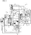
- FIG. 1illustrates systems and methods of the present invention for providing pre- and/or postdilution HF/HDF clearance modes, a bolus volume to the patient, a prime to the patient and/or a blood rinseback volume to the patient.
- FIG. 2illustrates one embodiment of a therapy fluid delivery manifold used in the systems and methods shown in FIG. 1 .
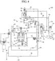
- FIGS. 3 and 4illustrate systems and methods of the present invention for removing ultrafiltrate from the patient and for filtering medical therapy fluid.
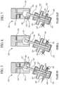
- FIGS. 5 to 7illustrate one embodiment of an ultrafiltrate pump used in the systems and methods shown in FIGS. 3 and 4 .
- the present inventionprovides systems and methods for improving medical fluid delivery systems, such as hemodialysis (“HD”), hemofiltration (“HF”) and hemodiafiltration (“HDF”) systems.
- systems and methods for selectively performing pre- and postdilution HF and HDF clearance modesare provided.
- systems and methods for providing bolus, prime and rinseback fluid volumes during/after HD, HF and HDF therapiesare provided.
- improved systems and methods for removing ultrafiltrate from the patientare provided.
- the present inventionprovides an improved filtration configuration and method.
- System 10in one embodiment is part of a machine that can perform HD, HF or HDF as selected by a doctor or nurse.
- the machineis typically used in a treatment center and in one embodiment generates dialysis solution via generation unit 12 .
- One suitable dialysate generation unit 12 for system 10is described in the maintenance manual for Baxter's System 1000® therapy machine. It should be appreciated from the disclosure herein, however, that the present invention is not limited to dialysate delivery systems or in-center systems but instead applies to any suitable medical fluid therapy treatment.
- system 10includes a dialysate flow path 20 and an extracorporeal or blood circuit 70 .
- dialysate flow path 20fluid generated via generation unit 12 is pumped via a supply pump 14 through a supply regulator 16 , which sets the maximum pressure of the dialysate in the flow path.
- Dialysate path 20employs a number of flow control devices that ensure that the desired amount of fluid is delivered to and removed from the patient (described in commonly owned patent U.S. Pat. No. 5,486,286, the teachings of which are incorporated herein by reference).
- dialysate flow path 20includes a flow equalizer or balancing chamber 30 and an ultrafiltrate flowmeter 50 .
- Flow equalizer 30includes a pair of fixed volume chambers 32 and 34 that each have a flexible membrane within, creating four variable volume cavities C 1 , C 2 , C 3 and C 4 .
- the volume in variable cavity C 1is inversely proportional to the volume in variable cavity C 2 .
- the volume in variable cavity C 3is inversely proportional to the volume in variable cavity C 4 .
- the two chamber pairs 32 and 34are provided so that one fixed volume chamber 32 or 34 pumps fluid to the filter/dialyzer, while at the same time, a second fixed volume chamber 32 or 34 pumps an equal amount of fluid from the filter/dialyzer.
- Match flow equalizer or balancing chamber 30therefore ensures that any fluid going through equalizer 30 is in turn removed from equalizer 30 , resulting in a net fluid gain or loss to the patient of zero.
- Cavities 32 and 34also alternate so that in each stroke fluid is pumped to and from the patient, resulting in a steady or non-pulsitile flow profile.
- Cavities 32 and 34operate with inlet valves 36 and outlet valves 38 , which are alternated to achieve the above-described flow equalization.
- those valvesare configured to enable one of the chamber pairs 32 or 34 to receive dialysate flowing through line 18 from regulator 16 to fill one of the cavities C 2 or C 4 . That filling action causes a corresponding one of the cavities C 1 or C 3 to decrease in volume and thereby push used or spent dialysate that filled cavity C 1 or C 3 in the previous stroke out line 22 , through an output pressure equalizer 24 , through a blood leak detector 26 and flow restrictor 28 to drain line 40 .
- a dialysate pressure pump 42is pulling spent dialysate from filter/dialyzer 44 and pushing that spent dialysate through a pressure regulating recirculation loop 46 to the other flow chamber pair 32 or 34 .
- Pump 42pushes fluid into one of the variable spent dialysate cavities C 1 or C 3 .
- the increasing volume of spent dialysate in the variable chambernecessarily decreases a like volume of fresh dialysate that filled variable cavity C 2 or C 4 in the previous stroke, pushing same toward the patient.
- Fresh dialysateis pushed out line 48 , through output pressure equalizer 24 , through a first ultrafilter 52 , through a portion of filtration line 88 , through a second ultrafilter 54 and through a dialysate monitoring manifold 56 . Suitable ultrafilter brands are discussed below. From manifold 56 , fresh filtered fluid flows either through a three-way bypass valve 58 , out bypass valve through line 60 into filter/dialyzer 44 or out through substitution port 86 , through the remainder of filtration line 88 and to blood circuit 70 .
- bypass line 62extends from bypass valve 58 and extends either into post-dialyzer line 64 , leading to pressure regulating recirculation loop 46 , or alternatively extends into rinse line 66 and through rinse valve 68 to drain 40 .
- Bypass line 62 , rinse line 66 and rinse valve 68enable various system components to be rinsed or cleaned prior to the beginning of therapy.
- Blood circuit 70includes an arterial access line 72 and a venous access line 74 .
- Arterial access line 72includes a Y-connection 76 that connects to a dialysate input line described below.
- Arterial line 72carries blood from patient 78 to an arterial drip chamber 80 .
- Bloodis transferred through extracorporeal circuit 70 via a peristaltic blood pump 82 .
- Pump 82pumps blood from arterial line 72 , through drip chamber 80 , to the blood inlet of dialyzer 44 .
- the bloodis pumped through the inside of membranes contained within the dialyzer, wherein diffusive transport of toxins and waste products from the blood takes place, and from the output of dialyzer 44 into a venous drip chamber 84 , through venous access line 74 , and back to patient 78 .
- Predialyzer dialysate line 60 , dialyzer 44 , postdialyzer line 64 and the remainder of dialysate flow path 20are maintained at a pressure lower than that of the blood within circuit 70 , resulting in the convective transport of waste out of the membranes within dialyzer 44 and a transport of waste and other undesirable substances from the patient's blood.
- System 10is additionally or alternatively capable of performing hemofiltration, in which solution flows along filtration line 88 , through substitution port 86 , through microfilter/ultrafilter 90 , through postfilter line 92 , through substitution fluid pump 94 and through a pre/postdilution fluid manifold 100 , directly to blood circuit 70 .
- Filter 90 in one embodimentis a microfilter.
- One suitable microfilteris a PallTM GelmanTM single use 0.22 micron filter.
- filter 90is an ultrafilter.
- One suitable reusable ultrafilteris a MedicaTM DiapureTM 28 filter.
- One suitable single use ultrafilteris a MedicaTM 150u filter.
- microfiltersdiffer from ultrafilters in the capability of the different filters in removing small particles. In general, ultrafilters can remove smaller particles than can microfilters.
- microfilterincludes filters having a membrane pore or membrane opening size of about 1000 to about 105 Angstroms (“ ⁇ ”), which effectively filters particles, such as red blood cells, yeast, fungi, bacteria and some proteins.
- ultrafilteras used herein includes filters having a membrane pore or membrane opening diameter or length of about 10 to about 1000 ⁇ , which effectively filters particles such as endotoxins (pyrogen), viruses and proteins.
- the ultrafilters used in the present inventionhave a range of pore sizes of about 10 to about 40 ⁇ .
- Filter 90operates with ultrafilters 52 and 54 to ensure that a sterile or injectable quality fluid is pumped via substitution pump 94 into the substitution fluid manifold 100 .
- Fluidis pumped via pump 94 , through Y-connection 102 into either postdilution line 104 or predilution line 106 .
- a cap 108is shown removed from a union 109 located at the end of pigtail 126 in line 106 .
- Manifold 100in an alternative embodiment provides only postdilution line 104 and pigtail 126 , wherein remainder of line 106 is removed and the corresponding output from Y-connector 102 is capped off via cap 108 . The remainder of line 106 can then be selectively added to pigtail 126 by removing cap 108 .
- predilution line 106is fully connected, system 10 can perform either pre- and/or postdilution HF and HDF as desired.
- postdilution line 104extends to the venous drip chamber 84 .
- Predilution line 106extends in one embodiment to a Y-connector or T-connector 76 positioned in a line 73 , which is located between pump 82 and drip chamber 80 .
- line 106(shown in phantom) extends via a solenoid valve 77 (in phantom) to a second Y-connector or T-connector 79 located in arterial access line 72 , which feeds into post-pump line 73 .
- the alternative embodimentis used with a rinseback feature described below.
- predilution line 106it is advantageous to connect predilution line 106 to arterial access line 72 via connector 79 when system 10 is combined with the bolus, prime and rinseback features described below. It should be appreciated however that the predilution therapy operates equally as well with line 106 connected to arterial access line 72 via connector 79 or to line 73 via connector 76 .
- a check valve 110is placed in postdilution line 104 , which allows fluid to flow only in the direction from pump 94 to blood circuit 70 , preventing blood from backing up through lines 92 and 88 into filters 52 and 54 or other parts of dialysate flow path 20 .
- a check valve 112is placed in predilution line 106 to prevent blood from backing into dialysate flow path 20 from predilution line 106 .
- Postdilution line 104includes a pinch clamp 114 .
- Predilution line 106likewise includes a pinch clamp 116 .
- Suitable pinch clamps for system 10are provided for example by MedicaTM, Model M03122.
- Clamps 114 and 116are electrically operated, pneumatically operated or are otherwise controlled via a microprocessor of system 10 to be opened and closed selectively as specified by the therapy.
- Manifold 100 of system 10enables HF or HDF therapy to occur: (i) via postdilution clearance only by opening valve 114 and closing valve 116 throughout therapy; (ii) via predilution clearance only by opening valve 116 and closing valve 114 throughout therapy; (iii) via pre- and postdilution clearance modes by sequentially opening valve 114 , while valve 116 is closed and then reversing that state and opening valve 116 , while valve 114 is closed; or (iv) via pre- and postdilution clearance modes simultaneously by opening valves 114 and 116 simultaneously.
- valves 114 and 116could instead be needling-type valves that selectively allow a desired percentage flow to pass through lines 104 and 106 .
- needling valvescan be placed in combination with on/off valves 114 and 116 , so that there are valved flow restriction settings and on/off control for both pre- and/or postdilution clearance modes.
- the operatorsets the overall target substitution volume into the machine employing system 10 .
- the operatorthen enters a percentage rate or percentage volume of pre- versus postdilution fluid flow.
- the single substitution pump 94runs continuously.
- the clamps 114 and 116alternate to achieve the desired pre- and postdilution clearance rates.
- the desired percentage breakdownis two-thirds postdilution and one-third predilution and the total flowrate is 150 ml/min
- the postdilution clampcould be closed for five seconds, while the predilution clamp 116 is open. Afterward, that state is reversed so that the predilution clamp 116 is closed, while the postdilution clamp 114 is open for the next ten seconds.
- That sequenceis repeated throughout therapy, or at least the portion of therapy that includes convective clearance.
- flow restrictionsare placed in lines 104 and 106 and set to produce the desired two-thirds postdilution of one-third predilution profile, while valves 114 and 116 are opened throughout the convective clearance portion of the therapy.
- the goal of diverting some of the convective flow from postdilution to predilutionis to prevent hemoconcentration while providing a predominantly postdilution treatment. To that end, it is desirable not to cycle the valves over too long a period so that such a condition could occur. On the other hand, it is also desirable not to cycle the valves too frequently for wear and maintenance purposes. The desired cycle time for the valves is therefore chosen to accommodate both of those factors.
- a second primary embodiment of the present inventioninvolves the ability of system 10 to perform not only a priming sequence, but to also provide a bolus of fluid to the patient as needed and to perform blood rinseback at the end of therapy.
- the bolus feature and blood rinseback featureare described hereafter in turn.
- the bypass valve 58is set so that dialysate flow no longer flows through predialyzer line 60 but instead bypasses the filter/dialyzer 44 and line 60 and flows alternatively through bypass line 62 .
- Rinse valve 68is closed so that dialysate flowing through line 62 tees into dialysate return line 64 , which shunts the fluid through match flow equalizer 30 to drain 40 .
- the bypass valve 58 configurationhas the effect of modifying the dialysate flow path 20 so that dialysate flow bypasses filter/dialyzer 44 .
- Recirculation loop 46helps to control pressure at the inlet of the flow equalizer 30 .
- recirculation loop 46operates with input pressure equalizer 118 and supply regulator 16 .
- Supply pump 14sets a pressure along line 18 . That pressure in line 18 moves a diaphragm within input pressure equalizer 118 back and forth, which either restricts an orifice that builds pressure in loop 46 or opens the orifice lowering the pressure in the loop, which in turn allows more or less fluid to circulate within loop 46 .
- bypass valve 58Besides de-energizing bypass valve 58 so that dialysate flows through bypass line 62 , shutting off flowmeter 50 , an isolate valve 120 placed in postdialyzer line 64 is closed. Valves 58 and 120 completely isolate filter/dialyzer 44 from the remainder of dialysate flow path 20 . To create the bolus volume, with filter/dialyzer 44 isolated, purge valve 122 is opened to drain.
- a portion of the fluid flowing from flow equalizer 30 to bypass valve 58flows through filtration line 88 , out of substitution port 86 , through filter 90 , through postfilter line 92 and is pumped via substitution pump 94 and postdilution line 104 (or predilution line 106 ) through venous drip chamber 84 , which purges any air from the solution, allowing an injectable quality bolus or volume of fluid to flow into patient 78 via venous access line 74 .
- valve 122is connected to an open source of fluid, namely, from fluid pumped via flow equalizer cavities C 1 and C 3 , through blood leak detector 26 , through flow restrictor 28 , through line 125 and though line 126 (shown with dual directionally pointed arrows), a volumetric equivalent to the fluid pumped to the extracorporeal circuit 70 via pump 94 can be infused into the system between the pre and post flow equalizers of equalizer 30 .
- the fluid flowsgoes through valve 122 , the fluid flows through filters 52 , 54 and 90 and is monitored for proper conductivity and temperature. Pump 94 will shut down if any of those measurements is outside of a correct range.
- the control scheme of system 10is operable to manually or automatically initiate the bolus volume.
- the control schemeautomatically commences the bolus feature upon receiving an appropriate signal from a biosensor, such as a hemoconcentration sensor, a blood volume sensor, an electrolyte sensor, an oxygen sensor and any combination thereof.
- TMPtransmembrane pressure
- Flow equalizer 30requires an equal volume of fluid to flow from line 18 to the equalizer as the volume flowing to equalizer 30 from recirculation loop 46 . It should be appreciated that because there is a volume of fluid being delivered to the patient and no fluid can be pulled from the patient with dialyzer 44 isolated, less fluid would return to flow equalizer 30 through line 62 , compared to the amount of fresh fluid delivered to flow equalizer 30 from source 12 . Accordingly, a makeup source of fluid is needed. For example, if supply pump 14 delivers 300 ml/min to flow equalizer 30 and 100 ml/min is pulled through substitution port 86 to the patient, only 200 ml/min will return through bypass line 62 , postdialyzer line 64 , recirculation loop 46 to flow equalizer 30 . The fluid return is deficient by 100 ml/min with respect to the 300 ml/min global supplied via source 12 , and such deficiency will cause flow equalizer 30 to operate improperly.
- purge valve 122which operates with ultrafilter 52 , is opened during the bolus infusion as discussed above.
- Purge valves 122 and 124operate normally with ultrafilters 52 and 54 , respectively, to enable the filters to be rinsed prior to therapy. Opening purge valve 122 enables the additional needed fluid, e.g., the additional 100 ml/min, to be pulled through lines 125 and 126 and into the dialysate flow path 20 . Liquid pulled through drain line 126 has previously flowed through dialyzer 44 and been pumped to drain 40 after passing through flow equalizer 30 . Accordingly, the additional fluid pulled through line 126 needs to be sterilized to be of an injectable quality.
- the filters 52 and 54 and additional disposable filter 90 in filtration line 88achieve that requirement. That is, fluid entering system 20 through purge valve 122 flows through ultrafilters 52 and 54 , out substitution port 86 , through a third ultrafilter or microfilter 90 and ultimately to patient 78 .
- Filters 52 and 54 in one embodimentare large surface area, reusable filters.
- Disposable filter 90can be an ultrafilter or a microfilter. Placing three filters in series enables system 10 to have triple redundancy during normal operation and for the bolus infusion.
- dialysate monitoring manifold 56which includes a dialysate conductivity probe, temperature sensor, a flow sensor and a dialysate pressure transducer will trip an alarm upon which substitution pump 94 is shut down.
- substitution pump 94is shut down, the configuration of the peristaltic pump 94 is such that the rotating head clamps the tubing off at a point along the tubing wrapped around the pump head, effectively stopping flow of fluid at that point.
- the substitution pump 94pumps the volume through a check valve, such as check valve 110 of post dilution line 104 , into venous drip chamber 84 .
- a check valvesuch as check valve 110 of post dilution line 104
- the bolus solution volumecan be implemented via pre- and postdilution manifold 100 discussed above. To do so, pinch clamp 114 is opened to allow the bolus volume to pass through check valve 110 , pass by clamp 114 and travel via line 104 to drip chamber 84 or, pinch clamp 116 is opened to allow the bolus volume to pass through check valve 112 , pass by clamp 116 via line 106 and travel to drip chamber 80 . From drip chamber 80 or 84 the bolus volume travels via venous access line 74 to patient 78 .
- the amount of the bolus volumeis either predetermined or set by the operator upon initiating the bolus function, for example, via a touch screen controller. In one embodiment, the bolus amount is set into the machine employing system 10 via a keypad on the touch screen. The amount of bolus can be controlled, for example, by monitoring the number of rotations of substitution pump 94 or by pumping until a desired setting is achieved on one of the biosensors described above.
- isolate valve 120is opened, purge valve 122 is closed, and bypass valve 58 is energized to allow dialysate to flow through predialyzer line 60 , and not to line 62 .
- Opening valves 120 and 58re-establishes fluid communication with dialyzer 44 .
- the TMP limitsare accordingly reset or reopened.
- one strokecan be taken of the UF flowmeter 50 to help create a positive transmembrane pressure when isolate valve 120 is opened. That procedure may be helpful in achieving a set UF target for the patient.
- the blood rinseback feature of the present inventionoperates in a similar manner to the bolus infusion feature described above.
- the blood rinseback amountcan be set at the time the procedure is started or preset according to a prescription or therapy protocol. Again, a touch screen having a keypad can be used to set the rinseback amount.
- the rinseback functioncan be initiated manually in one embodiment, the present invention also contemplates automatically starting the rinseback function at the end of treatment.
- the blood rinseback procedurecan be controlled by inputting a set amount of fluid, it is also possible to control the feature via a blood detector placed near the patient end of venous access line 74 , which detects when no more blood is present in blood circuit 70 and stops substitution pump 94 accordingly and automatically.
- each of the major steps described above for performing the bolus infusion procedureis also performed for the blood rinseback procedure.
- the proceduresare performed at different times during therapy because the different procedures are for different purposes.
- the bolus function as described aboveis initiated manually or automatically when the patient appears to have become or is becoming hypotensive.
- Blood rinsebackis performed at the end of treatment to push any blood remaining in the system back to patient 78 .
- both proceduresinvolve the use of isolate valve 120 and bypass valve 58 to isolate dialyzer 44 from the remainder of dialysate flow path 20 .
- purge valve 122is opened to enable an equal amount of fluid delivered to patient 78 to be drawn via drain line 126 , through filters 52 , 54 and 90 into dialysate flow path 20 , so that flow equalizer 30 operates properly.
- the bolus functioncan be delivered to extracorporeal circuit 70 .
- the bolus volumecan be delivered to venous drip chamber 84 .
- the rinseback amountis delivered on the other hand to the end of or to a point of arterial access line 72 marked by Y-connector or T-connector 79 , which is appropriate to clean blood in arterial line 72 through pump 82 , through arterial drip chamber 80 , through dialyzer 44 , through venous drip chamber 84 and finally through venous access line 74 to patient 78 .
- Connector 79is connected to predilution line 106 via solenoid valve 77 to enable automatic control of the rinseback feature.
- pre- and postdilution manifold 100in combination with the rinseback feature of system 10 and to deliver the rinseback volume from substitution pump 94 , through Y-connector 102 , through predilution line 106 , including check valve 112 and pinch valve 116 , through line 106 and solenoid 77 , to the arterial access line 72 at connector 79 .
- FIGS. 1 and 2show a cap 108 that connects to a union 109 located at the end of pigtail 126 . It is possible that instead of using the already existing predilution line 106 when the rinseback volume is needed, cap 108 is removed from the union 109 of pigtail 126 and a substitution line (not illustrated) is manually coupled to the end of pigtail 126 and to either connector 79 of line 72 after being uncoupled from the patient or to connector 76 located in line 73 , for example, by removing a cap from connection 76 . In a preferred embodiment, that substitution line would include at its end a one-way valve or check valve, such as check valve 112 .
- substitution linemanually to connectors 76 or 79
- blood pump 82is shut down and either a cap is removed from connector 79 or the arterial access line 72 is disconnected from an arterial needle of the catheter that is inserted into patient 78 .
- a clampis closed at the end of the arterial needle so that no blood is lost from the patient.
- Connector 76 or 79is then connected to the substitution line, which is also connected to the end of pigtail 126 .
- a luer connector with a rotating hubis provided in one embodiment at the end of arterial access line 72 to couple the line directly to the substitution line extending from pigtail 126 . After that connection is made, the rinseback volume is delivered as described above.
- the known way to provide a rinsebackis to connect a saline bag to the arterial access line 72 after disconnecting such line from the arterial needle. Thereafter, saline flows from the saline bag through the arterial access line 72 to provide the saline rinseback or flush.
- Both the manual and automatically operating embodiments described aboveenable system 10 to eliminate the need for a separate saline or injectable solution supply to provide the blood rinseback.
- the prime feature of the present inventionoperates using the apparatus described above in connection with FIG. 1 for the bolus and rinseback features to prime the extracorporeal circuit 70 prior to therapy.
- the primeincludes a volume of fluid, such as dialysate, that is delivered at the beginning of the therapy to remove air from the extracorporeal circuit.
- the prime featureis used within a system or with a controller that is operable to receive an operator input to commence delivery of the prime. Alternatively, the system or controller is operable to commence delivery of the prime automatically at the beginning of therapy.
- the amount or volume of the primeis entered by an operator when commencing delivery of the prime. The amount or volume can be predetermined prior to commencement of therapy. Alternatively, the amount or volume is delivered until air is no longer sensed in the extracorporeal circuit.
- FIGS. 3 to 7another primary embodiment of the present invention is illustrated.
- FIGS. 3 and 4illustrate systems 150 and 160 , respectively, which include many of the same components described above in connection with FIGS. 1 and 2 . Those components are marked with the same element numbers as used in FIGS. 1 and 2 . The description of those elements including each of the alternatives discussed above in connection with FIGS. 1 and 2 apply equally to like element numbers in FIGS. 3 and 4 .
- FIGS. 1 and 2One primary difference between the embodiments described in FIGS. 1 and 2 compared with the systems 150 and 160 of FIGS. 3 and 4 is that the UF flowmeter 50 is removed in FIGS. 3 and 4 .
- the function of the UF flowmeter so shown in FIGS. 1 and 2is to remove fluid from the patient 78 that has accumulated in the patient's body over the time between the patient's last therapy and the current therapy.
- One of the problems that occurs with kidney failureis that the patient in many instances loses some or all of the ability to urinate. The fluid that would otherwise be removed from the patient via urination becomes stored in the patient's blood and surrounding tissues.
- UF flowmeter 50operates to remove an additional amount of fluid from the patient, which is equivalent to the amount of fluid gained by the patient between treatments.
- UF flowmeter 50operates in a similar manner to one of the chamber pairs 32 and 34 of flow equalizer 30 .
- UF flowmeter 50defines a fixed volume chamber 132 that is separated by a diaphragm into two alternating variable volume cavities C 5 and C 6 .
- Fixed volume chamber 132is sized in a desired relation to the matched volume chambers 32 and 34 .
- Inlet valves 136 and 138 of UF flowmeter 50can be cycled with inlet valves 36 and outlet valves 38 of flow equalizer 30 . In that manner, a known volume of fluid is removed with each stroke or valve cycle.
- valves 136 and 138alternate so that cavity C 6 fills and pushes fluid previously drawn into cavity C 5 through one of the outlet valves 138 , whereafter the valves switch so that cavity C 5 fills and pushes the previously filled volume in cavity C 6 through the other outlet valve 138 .
- UF flowmeter 50is an effective but relatively complicated device. Also, the failure of one of the valves 136 or 138 can cause an uncontrolled flow during half of a cycle of the diaphragm, resulting in an overfiltration of the patient.
- Another potential problem with system 10 illustrated in FIG. 1is that air can become trapped in ultrafilters 52 and 54 . It is possible for air to also become trapped in disposable filter 90 , however, it is more likely that air enters reusable filters 52 and 54 .
- dialysate pump 42is placed directly in front of a UF removal line 134 , which leads to UF flowmeter 50 . That configuration can lead to the clogging of UF meter 50 .
- the purge valves 122 and 124are closed during normal therapy in system 10 , so that there is no flow across the outside the membranes of those filters (operational flow through filters is from the inlet of the filters to outside the membranes inside the ultrafilters, through the walls of the membranes, and through the inside of the membranes out the outlet of the ultrafilters).
- the material that is filtered in filters 52 and 54remains inside the filters until a rinse cycle is performed after therapy, when purge valves 122 and 124 are opened. That is, bacteria and endotoxin that are filtered by the membranes inside ultrafilters 52 and 54 remain inside those filters throughout the duration of therapy.
- Another potential problem in system 10 of FIG. 1is that the only way to detect if one of the purge valves 122 and 124 is not functioning properly is to detect an increase or decrease in TMP. A TMP error that is not examined and diagnosed properly by an operator could result in a UF error for the patient.
- Ultra pure dialysate for online HF and online HDF treatmentsis enabled by locating ceramic pump 140 downstream from the single purge valve 122 in system 150 of FIG. 3 and downstream of dual purge valves 122 and 124 in system 160 of FIG. 4 . In both cases, the purge valves are located downstream from the rinse outlet 142 of one of the ultrafilters 52 or 54 . Fluid that reaches pump 140 is therefore fluid that is to be removed along drain line 126 .
- pump 140is a ceramic rotating, reciprocating piston pump in one embodiment, which is advantageous because it does not establish fluid communication between the inlet and outlet of the pump. That pump configuration enables the pump to fail safe, where uncontrolled fluid flow does not occur.
- Locating ceramic pump 140 downstream of purge valves 122 and 124provides additional advantages. That is, besides isolating the inlet and outlet of the pump and thereby eliminating the potential for UF error due to component failure, locating pump 140 predialyzer reduces the possibility of the UF pump becoming clogged or corrupted with organic substances. That is, UF removed to drain from pump 140 is clean or sterile solution from generation unit 12 . The likelihood of a UF occurring error due to endotoxin and bacteria building up in the UF removal device is therefore substantially decreased in systems 150 and 160 of the present invention.
- systems 150 and 160provide a continual rinse along the outside of the membranes within those filters.
- the purge valves 122 and 124are cycled, e.g., at fifty percent for each valve, so that both filters 52 and 54 are rinsed and cleaned as therapy takes place.
- the rinse along the outer surface of the membranes of filters 52 and 54also removes air from the filters continuously or semi-continuously during treatment.
- pump 140removes fresh dialysate as UF
- dialyzer 44functions as described above to diffuse waste products from the patient's blood. Waste is also removed through convective transport caused by the direct infusion of blood into the extracorporeal circuit 70 . That waste is then pumped through balancing chambers 30 , via dialysate pump 42 , to drain.
- the UF pumping of fresh dialysate via pump 140does not alter the effectiveness of the therapies of systems 150 and 160 .
- FIGS. 5 to 7illustrate one embodiment of UF pump 140 , which is a rotating and reciprocating piston pump.
- FIGS. 5 to 7illustrate the rotating reciprocating piston pump 140 in three states, namely, a fluid-in state in FIG. 5 , a dwell state in FIG. 6 and a fluid-out state in FIG. 7 .
- One suitable rotating reciprocating piston pumpis supplied by Diener Precision Pumps, Embrach, Switzerland.
- valve 140includes a rotating chamber 142 defining an opening 144 that receives an end of a rotating and reciprocating piston 146 .
- the end of the piston 146includes an arm 148 with a ball bearing type head 152 that is received slidingly inside a coupling aperture 154 , which is in fluid communication with opening 144 .
- head 152is carried by the outer wall of coupler opening 154 , which in turn rotates arm 148 and shaft 146 .
- head 152 , arm 148 and shaft 146are also translated in a direction of the angle of shaft 146 back and forth depending on the rotational location of coupler opening 154 during rotation of chamber 142 .
- piston head 152is pulled a further distance away from a pump body 158 than the vertical distance between piston head 152 and body 158 in the fluid-out state of pump 140 in FIG. 7 .
- Piston head 152is accordingly at an intermediate relative distance away from body 158 in the dwell state of pump 140 shown in FIG. 6 . It should be appreciated, therefore, that the rotation of drive shaft 156 causes both a rotational motion and translational motion of shaft 146 relative to fixed body 158 .
- Body 158defines port openings 162 that enable a lubricant such as water to lubricate the sliding engagement between shaft 146 and the inner bore of body 158 .
- Body 158also defines inlet and outlet ports 164 and 166 , respectively.
- the lower end of shaft 146defines a notch 168 .
- Notch 168 in the fluid-in state of pump 140enables fluid to enter via inlet port 164 into a pump chamber 170 . Importantly, in the fluid-in state, no fluid communication exists between pump chamber 170 and outlet port 166 . In the dwell state of pump 140 in FIG.
- shaft 146has rotated to a position wherein notch 168 does not face or communicate with either port 164 or 166 , so that no fluid communication takes place between pump chamber 170 and the openings of ports 164 and 166 .
- shaft 146has rotated to a position wherein notch 168 enables fluid communication to exist between pump chamber 170 and outlet port 166 .
- no fluid communicationexists between pump chamber 170 and inlet port 164 .
- the volume in pump chamber 170increases, creating a vacuum and drawing fluid into chamber 170 .
- the volume in pump chamber 170has decreased from the volume in the fluid-in state ( FIG. 5 ), creating a positive pressure inside chamber 170 .
- the shaft 146moves from the dwell state ( FIG. 6 ) to the fluid-out state ( FIG. 7 )
- the volume in chamber 170further decreases and pushes fluid out of outlet port 166 .
- inlet port 164never communicates fluidly with outlet port 166 , pump 140 even upon a failure or loss of power cannot allow an uncontrolled UF flow, decreasing significantly the inherent error potential in comparison to the error inherent in the valves 136 and 138 of prior flowmeter 50 and with the flowmeter 50 itself, as well as potential UF errors that could occur from a failure of one of the purge valves 122 and 124 .
- the amount of ultrafiltrate removed from the patientis controlled in one embodiment by monitoring the number of rotations of shaft 146 .
- Rotating, reciprocating piston pump 140is inherently accurate. If needed, however, a flow measuring device can be placed in drain line 126 to monitor the output of pump 140 .
- Pump 140may also be used with each of the embodiments described above in connection with FIGS. 1 and 2 , including the pre- and postdilution features, the bolus feature and the rinseback purge.
- FIGS. 3 and 4can employ the manifold 100 discussed above in connection with FIG. 1 however same is not shown for the sake of clarity.
- pump 140rotates in the opposite direction to pull fluid from line 126 shown with dual directional arrows in FIGS. 3 and 4 in the same manner as discussed above.
- the present invention in FIGS. 1 and 4shows an improved filtration configuration.
- an electrolyte solutionsuch as dialysate is filtered by ultrafilters and/or microfilters to achieve an injectable quality output.
- the present inventionemploys three filters in series without an intervening pump placed between the filters.
- the filterseach add successive log reduction of bacteria and endotoxin.
- the pumpbecomes a place where bacteria and endotoxin accumulate during quiescent times, such as when the system is off. Accordingly, the present invention eliminates the need for placing a pump between the in-series filters. It should be appreciated however that sensors and other flow components besides pumps are contemplated to be placed between the in-series filters.
- filters 52 , 54 and 90In an attempt to remove as much bacteria and endotoxin as possible, the present systems shown in FIGS. 1 and 4 uses three filters in series, namely, filters 52 , 54 and 90 . Those filters help to ensure the quality of the solution by providing successive log reductions of bacteria and endotoxin.
- Filters 52 , 54 and 90can be any combination of single use or reusable ultrafilters, microfilters or other endotoxin/bacteria reducing devices, such as a clarigen dialguard column.
- filters 52 and 54are reusable and the hydraulics path 88 is constructed without complex hydraulic features, such as a pump, after the first filter in the system, thereby reducing risk of microbial and biofilm growth after the solution is first filtered.
- filter 90is a single use microfilter.
- the filtration configuration of FIGS. 1 and 4employs no pumps between filters 52 , 54 or 90 .
- the flow of medical fluid from filters 52 and 54passes through sterile tubing (and possibly other flow components) to the inlet of the next filter.
- sterile tubingand possibly other flow components
- only tubingis provided in one embodiment between filters 52 and 54 and only a single dialysate monitoring manifold 56 is placed between filters 54 and 90 . Limiting the components between filters to only simple tubing (and possibly sensor components) helps to prevent the proliferation of bacteria on complex surfaces and to ensure the efficacy of the disinfection.
- the purging function during the preparation phase of the medical fluid systems of the present inventionalso helps to remove bacteria or endotoxin that may have grown since the machine was last used. With the simplified flow path between filters 52 , 54 and 90 , however, very little growth occurs.
- Placing pumps before and after the filters 52 , 54 and 90enables the flowrate of fluid pumped, e.g., via dialysate pump 42 , through the filters to be higher than the flowrate pumped, e.g., via infusion pump 94 , to the patient 78 .
- the systems of FIGS. 1 and 4can therefore be set so that that the medical fluid flow to patient 78 is only a portion (albeit a potentially large portion) of the total flow out of the filters, which can be reusable filters. For instance, if the systems are used for hemofiltration and are set to flow 250 ml/min of replacement fluid to patient 78 , the flow out of filters 52 , 54 and 90 can be 300 ml/min.
- the quality of the replacement fluidcan be ensured through the combined log reduction of the filters and because the filters to a large extent only have to filter contamination from the incoming medical solution.
- the resulting log reduction of the remaining filters in most instancesis still sufficient to provide a medical grade solution.
- the smooth clean surfaces in between the filtersare easily and effectively disinfected, preventing growth during quiescent periods.
Landscapes
- Health & Medical Sciences (AREA)
- Heart & Thoracic Surgery (AREA)
- Vascular Medicine (AREA)
- Animal Behavior & Ethology (AREA)
- Anesthesiology (AREA)
- Biomedical Technology (AREA)
- Hematology (AREA)
- Life Sciences & Earth Sciences (AREA)
- Engineering & Computer Science (AREA)
- General Health & Medical Sciences (AREA)
- Public Health (AREA)
- Veterinary Medicine (AREA)
- Urology & Nephrology (AREA)
- Cardiology (AREA)
- Emergency Medicine (AREA)
- External Artificial Organs (AREA)
Abstract
Description
Claims (21)
Priority Applications (1)
| Application Number | Priority Date | Filing Date | Title |
|---|---|---|---|
| US16/561,966US11672897B2 (en) | 2003-12-16 | 2019-09-05 | Blood rinseback system and method |
Applications Claiming Priority (6)
| Application Number | Priority Date | Filing Date | Title |
|---|---|---|---|
| US10/738,446US7744553B2 (en) | 2003-12-16 | 2003-12-16 | Medical fluid therapy flow control systems and methods |
| US12/793,906US8430835B2 (en) | 2003-12-16 | 2010-06-04 | Renal therapy blood cleansing system with balance chamber and bolus, rinseback or prime volume feature |
| US13/833,903US9211370B2 (en) | 2003-12-16 | 2013-03-15 | Renal therapy blood cleansing system with isolation feature |
| US14/967,646US10195332B2 (en) | 2003-12-16 | 2015-12-14 | Renal therapy blood cleansing system with selective valve feature |
| US16/266,924US10426882B2 (en) | 2003-12-16 | 2019-02-04 | Blood rinseback system and method |
| US16/561,966US11672897B2 (en) | 2003-12-16 | 2019-09-05 | Blood rinseback system and method |
Related Parent Applications (1)
| Application Number | Title | Priority Date | Filing Date |
|---|---|---|---|
| US16/266,924ContinuationUS10426882B2 (en) | 2003-12-16 | 2019-02-04 | Blood rinseback system and method |
Publications (2)
| Publication Number | Publication Date |
|---|---|
| US20190388604A1 US20190388604A1 (en) | 2019-12-26 |
| US11672897B2true US11672897B2 (en) | 2023-06-13 |
Family
ID=34654227
Family Applications (6)
| Application Number | Title | Priority Date | Filing Date |
|---|---|---|---|
| US10/738,446Expired - Fee RelatedUS7744553B2 (en) | 2003-12-16 | 2003-12-16 | Medical fluid therapy flow control systems and methods |
| US12/793,906Expired - Fee RelatedUS8430835B2 (en) | 2003-12-16 | 2010-06-04 | Renal therapy blood cleansing system with balance chamber and bolus, rinseback or prime volume feature |
| US13/833,903Expired - Fee RelatedUS9211370B2 (en) | 2003-12-16 | 2013-03-15 | Renal therapy blood cleansing system with isolation feature |
| US14/967,646Expired - LifetimeUS10195332B2 (en) | 2003-12-16 | 2015-12-14 | Renal therapy blood cleansing system with selective valve feature |
| US16/266,924Expired - LifetimeUS10426882B2 (en) | 2003-12-16 | 2019-02-04 | Blood rinseback system and method |
| US16/561,966Active2026-05-01US11672897B2 (en) | 2003-12-16 | 2019-09-05 | Blood rinseback system and method |
Family Applications Before (5)
| Application Number | Title | Priority Date | Filing Date |
|---|---|---|---|
| US10/738,446Expired - Fee RelatedUS7744553B2 (en) | 2003-12-16 | 2003-12-16 | Medical fluid therapy flow control systems and methods |
| US12/793,906Expired - Fee RelatedUS8430835B2 (en) | 2003-12-16 | 2010-06-04 | Renal therapy blood cleansing system with balance chamber and bolus, rinseback or prime volume feature |
| US13/833,903Expired - Fee RelatedUS9211370B2 (en) | 2003-12-16 | 2013-03-15 | Renal therapy blood cleansing system with isolation feature |
| US14/967,646Expired - LifetimeUS10195332B2 (en) | 2003-12-16 | 2015-12-14 | Renal therapy blood cleansing system with selective valve feature |
| US16/266,924Expired - LifetimeUS10426882B2 (en) | 2003-12-16 | 2019-02-04 | Blood rinseback system and method |
Country Status (5)
| Country | Link |
|---|---|
| US (6) | US7744553B2 (en) |
| EP (1) | EP1699505B2 (en) |
| JP (2) | JP5007125B2 (en) |
| MX (1) | MXPA06006835A (en) |
| WO (1) | WO2005061026A2 (en) |
Families Citing this family (170)
| Publication number | Priority date | Publication date | Assignee | Title |
|---|---|---|---|---|
| US20030010718A1 (en) | 2001-07-12 | 2003-01-16 | Nxstage Medical, Inc. | Hemodilution cap and methods of use in blood-processing procedures |
| US6649063B2 (en) | 2001-07-12 | 2003-11-18 | Nxstage Medical, Inc. | Method for performing renal replacement therapy including producing sterile replacement fluid in a renal replacement therapy unit |
| US7686778B2 (en)* | 2003-01-15 | 2010-03-30 | Nxstage Medical, Inc. | Waste balancing for extracorporeal blood treatment systems |
| US8235931B2 (en) | 2003-01-15 | 2012-08-07 | Nxstage Medical, Inc. | Waste balancing for extracorporeal blood treatment systems |
| US8029454B2 (en) | 2003-11-05 | 2011-10-04 | Baxter International Inc. | High convection home hemodialysis/hemofiltration and sorbent system |
| US7744553B2 (en) | 2003-12-16 | 2010-06-29 | Baxter International Inc. | Medical fluid therapy flow control systems and methods |
| WO2006086490A1 (en) | 2005-02-07 | 2006-08-17 | Medtronic, Inc. | Ion imbalance detector |
| US20070073354A1 (en) | 2005-09-26 | 2007-03-29 | Knudson Mark B | Neural blocking therapy |
| US7713226B2 (en)* | 2006-01-06 | 2010-05-11 | Renal Solutions, Inc. | On demand and post-treatment delivery of saline to a dialysis patient |
| US10537671B2 (en) | 2006-04-14 | 2020-01-21 | Deka Products Limited Partnership | Automated control mechanisms in a hemodialysis apparatus |
| US9717834B2 (en)* | 2011-05-24 | 2017-08-01 | Deka Products Limited Partnership | Blood treatment systems and methods |
| US7794141B2 (en) | 2006-04-14 | 2010-09-14 | Deka Products Limited Partnership | Thermal and coductivity sensing systems, devices and methods |
| US8273049B2 (en) | 2007-02-27 | 2012-09-25 | Deka Products Limited Partnership | Pumping cassette |
| ES2564519T3 (en) | 2006-10-13 | 2016-03-23 | Bluesky Medical Group Inc. | Pressure control of a medical vacuum pump |
| PL2091592T3 (en)* | 2006-10-30 | 2014-09-30 | Gambro Lundia Ab | An extracorporeal blood chamber |
| WO2008053259A1 (en)* | 2006-10-30 | 2008-05-08 | Gambro Lundia Ab | Hemo(dia)filtration apparatus |
| CA2667604C (en)* | 2006-10-30 | 2011-07-12 | Gambro Lundia Ab | Medical fluid circuit unit |
| ES2401073T3 (en)* | 2006-10-30 | 2013-04-16 | Gambro Lundia Ab | Air separator for extracorporeal fluid treatment sets |
| US10463774B2 (en) | 2007-02-27 | 2019-11-05 | Deka Products Limited Partnership | Control systems and methods for blood or fluid handling medical devices |
| US8357298B2 (en) | 2007-02-27 | 2013-01-22 | Deka Products Limited Partnership | Hemodialysis systems and methods |
| US8562834B2 (en) | 2007-02-27 | 2013-10-22 | Deka Products Limited Partnership | Modular assembly for a portable hemodialysis system |
| US9028691B2 (en) | 2007-02-27 | 2015-05-12 | Deka Products Limited Partnership | Blood circuit assembly for a hemodialysis system |
| US8491184B2 (en) | 2007-02-27 | 2013-07-23 | Deka Products Limited Partnership | Sensor apparatus systems, devices and methods |
| US8409441B2 (en) | 2007-02-27 | 2013-04-02 | Deka Products Limited Partnership | Blood treatment systems and methods |
| US8425471B2 (en) | 2007-02-27 | 2013-04-23 | Deka Products Limited Partnership | Reagent supply for a hemodialysis system |
| US8042563B2 (en) | 2007-02-27 | 2011-10-25 | Deka Products Limited Partnership | Cassette system integrated apparatus |
| KR102444304B1 (en) | 2007-02-27 | 2022-09-19 | 데카 프로덕츠 리미티드 파트너쉽 | hemodialysis system |
| US20090107335A1 (en) | 2007-02-27 | 2009-04-30 | Deka Products Limited Partnership | Air trap for a medical infusion device |
| US8393690B2 (en) | 2007-02-27 | 2013-03-12 | Deka Products Limited Partnership | Enclosure for a portable hemodialysis system |
| US9408954B2 (en) | 2007-07-02 | 2016-08-09 | Smith & Nephew Plc | Systems and methods for controlling operation of negative pressure wound therapy apparatus |
| GB0715259D0 (en) | 2007-08-06 | 2007-09-12 | Smith & Nephew | Canister status determination |
| GB0715211D0 (en)* | 2007-08-06 | 2007-09-12 | Smith & Nephew | Apparatus |
| US12121648B2 (en) | 2007-08-06 | 2024-10-22 | Smith & Nephew Plc | Canister status determination |
| US7938792B2 (en)* | 2007-10-01 | 2011-05-10 | Baxter International Inc. | Adaptive algorithm for access disconnect detection |
| WO2009044221A1 (en)* | 2007-10-04 | 2009-04-09 | Gambro Lundia Ab | An infusion apparatus |
| US8771508B2 (en) | 2008-08-27 | 2014-07-08 | Deka Products Limited Partnership | Dialyzer cartridge mounting arrangement for a hemodialysis system |
| US8114276B2 (en) | 2007-10-24 | 2012-02-14 | Baxter International Inc. | Personal hemodialysis system |
| US20090204173A1 (en) | 2007-11-05 | 2009-08-13 | Zi-Ping Fang | Multi-Frequency Neural Treatments and Associated Systems and Methods |
| US10201647B2 (en) | 2008-01-23 | 2019-02-12 | Deka Products Limited Partnership | Medical treatment system and methods using a plurality of fluid lines |
| USD644730S1 (en) | 2008-04-11 | 2011-09-06 | Gambro Lundia Ab | Module for fluid transport of medical fluid and blood |
| US8192388B2 (en)* | 2008-07-25 | 2012-06-05 | Baxter International Inc. | System and method for detecting access disconnection |
| US12171922B2 (en) | 2008-08-27 | 2024-12-24 | Deka Products Limited Partnership | Blood treatment systems and methods |
| US20100051552A1 (en)* | 2008-08-28 | 2010-03-04 | Baxter International Inc. | In-line sensors for dialysis applications |
| US8255057B2 (en) | 2009-01-29 | 2012-08-28 | Nevro Corporation | Systems and methods for producing asynchronous neural responses to treat pain and/or other patient conditions |
| US9327121B2 (en) | 2011-09-08 | 2016-05-03 | Nevro Corporation | Selective high frequency spinal cord modulation for inhibiting pain, including cephalic and/or total body pain with reduced side effects, and associated systems and methods |
| JP2010127620A (en)* | 2008-11-25 | 2010-06-10 | Olympus Corp | Apparatus for treating biological tissue |
| ES2942684T3 (en) | 2009-04-22 | 2023-06-05 | Nevro Corp | Spinal cord modulation systems to induce paresthetic and anesthetic effects |
| EP3228350B1 (en) | 2009-04-22 | 2025-09-24 | Nevro Corporation | Device for selective high frequency spinal cord modulation for inhibiting pain with reduced side effects, and associated systems and methods |
| US8498710B2 (en) | 2009-07-28 | 2013-07-30 | Nevro Corporation | Linked area parameter adjustment for spinal cord stimulation and associated systems and methods |
| US9399091B2 (en) | 2009-09-30 | 2016-07-26 | Medtronic, Inc. | System and method to regulate ultrafiltration |
| EP2314332A1 (en) | 2009-10-21 | 2011-04-27 | Gambro Lundia AB | Medical fluid delivery system |
| CN104841030B (en) | 2009-10-30 | 2017-10-31 | 德卡产品有限公司 | For the apparatus and method for the disconnection for detecting intravascular access device |
| PL2504045T3 (en) | 2009-11-24 | 2020-11-16 | Fresenius Medical Care Deutschland Gmbh | Method for temporarily interrupting an extracorporeal blood treatment, control device and blood treatment device |
| JP5399218B2 (en)* | 2009-11-24 | 2014-01-29 | 日機装株式会社 | Blood purification equipment |
| US8753515B2 (en) | 2009-12-05 | 2014-06-17 | Home Dialysis Plus, Ltd. | Dialysis system with ultrafiltration control |
| JP5588692B2 (en)* | 2010-02-09 | 2014-09-10 | 日機装株式会社 | Dialysis machine |
| US8501009B2 (en) | 2010-06-07 | 2013-08-06 | State Of Oregon Acting By And Through The State Board Of Higher Education On Behalf Of Oregon State University | Fluid purification system |
| EP2727615B1 (en) | 2010-09-30 | 2015-11-04 | Gambro Lundia AB | An apparatus for extracorporeal blood treatment |
| DE102010043574A1 (en)* | 2010-11-08 | 2012-05-10 | Fresenius Medical Care Deutschland Gmbh | Manually open clamp holder with sensor |
| WO2012075198A2 (en) | 2010-11-30 | 2012-06-07 | Nevro Corporation | Extended pain relief via high frequency spinal cord modulation, and associated systems and methods |
| WO2012129501A2 (en) | 2011-03-23 | 2012-09-27 | Nxstage Medical, Inc. | Peritoneal dialysis systems, devices, and methods |
| US9861733B2 (en) | 2012-03-23 | 2018-01-09 | Nxstage Medical Inc. | Peritoneal dialysis systems, devices, and methods |
| DE102011016869A1 (en)* | 2011-04-13 | 2012-10-18 | Fresenius Medical Care Deutschland Gmbh | Apparatus and method for conveying a liquid to a filter unit of a medical treatment device |
| US8840790B2 (en) | 2011-04-27 | 2014-09-23 | Fenwal, Inc. | Systems and methods of controlling fouling during a filtration procedure |
| US9848778B2 (en) | 2011-04-29 | 2017-12-26 | Medtronic, Inc. | Method and device to monitor patients with kidney disease |
| US9456755B2 (en) | 2011-04-29 | 2016-10-04 | Medtronic, Inc. | Method and device to monitor patients with kidney disease |
| US9561316B2 (en) | 2011-04-29 | 2017-02-07 | Medtronic, Inc. | Intersession monitoring for blood fluid removal therapy |
| DE102011102492A1 (en)* | 2011-05-24 | 2012-11-29 | Fresenius Medical Care Deutschland Gmbh | A method of rinsing and / or filling a blood treatment device and blood treatment device |
| EP3205362B1 (en) | 2011-05-24 | 2022-07-06 | DEKA Products Limited Partnership | Hemodialysis system |
| US9999717B2 (en) | 2011-05-24 | 2018-06-19 | Deka Products Limited Partnership | Systems and methods for detecting vascular access disconnection |
| CN103889481B (en) | 2011-08-02 | 2016-03-09 | 美敦力公司 | Hemodialysis system with flow path with controlled compliance volume |
| EP2744537B1 (en) | 2011-08-16 | 2018-01-24 | Medtronic, Inc. | Modular hemodialysis system |
| JP2014533133A (en) | 2011-10-07 | 2014-12-11 | ホーム・ダイアリシス・プラス・リミテッドHome DialysisPlus, Ltd. | Purification of heat exchange fluids for dialysis systems |
| US12303631B2 (en) | 2011-11-04 | 2025-05-20 | Deka Products Limited Partnership | Medical treatment system and methods using a plurality of fluid lines |
| JP6027129B2 (en) | 2011-11-04 | 2016-11-16 | デカ・プロダクツ・リミテッド・パートナーシップ | Medical systems that use multiple fluid lines |
| EP2800592B1 (en) | 2012-01-04 | 2019-03-06 | Medtronic Inc. | Multi-staged filtration system for blood fluid removal |
| EP2666491B2 (en) | 2012-05-22 | 2020-08-12 | D.Med Consulting GmbH | Haemodialysis device |
| US9833614B1 (en) | 2012-06-22 | 2017-12-05 | Nevro Corp. | Autonomic nervous system control via high frequency spinal cord modulation, and associated systems and methods |
| US10905816B2 (en) | 2012-12-10 | 2021-02-02 | Medtronic, Inc. | Sodium management system for hemodialysis |
| EP2745864B1 (en)* | 2012-12-20 | 2017-01-18 | Gambro Lundia AB | Blood treatment apparatus, control method and computer program |
| CN104363938B (en) | 2012-12-31 | 2017-04-26 | 甘布罗伦迪亚股份公司 | Occlusion detection in delivery of fluids |
| US9713666B2 (en) | 2013-01-09 | 2017-07-25 | Medtronic, Inc. | Recirculating dialysate fluid circuit for blood measurement |
| US11565029B2 (en) | 2013-01-09 | 2023-01-31 | Medtronic, Inc. | Sorbent cartridge with electrodes |
| US11154648B2 (en) | 2013-01-09 | 2021-10-26 | Medtronic, Inc. | Fluid circuits for sorbent cartridge with sensors |
| US9707328B2 (en) | 2013-01-09 | 2017-07-18 | Medtronic, Inc. | Sorbent cartridge to measure solute concentrations |
| US9623164B2 (en) | 2013-02-01 | 2017-04-18 | Medtronic, Inc. | Systems and methods for multifunctional volumetric fluid control |
| US10010663B2 (en) | 2013-02-01 | 2018-07-03 | Medtronic, Inc. | Fluid circuit for delivery of renal replacement therapies |
| US9526822B2 (en) | 2013-02-01 | 2016-12-27 | Medtronic, Inc. | Sodium and buffer source cartridges for use in a modular controlled compliant flow path |
| US10850016B2 (en) | 2013-02-01 | 2020-12-01 | Medtronic, Inc. | Modular fluid therapy system having jumpered flow paths and systems and methods for cleaning and disinfection |
| US10543052B2 (en) | 2013-02-01 | 2020-01-28 | Medtronic, Inc. | Portable dialysis cabinet |
| US9144640B2 (en) | 2013-02-02 | 2015-09-29 | Medtronic, Inc. | Sorbent cartridge configurations for improved dialysate regeneration |
| US9827361B2 (en) | 2013-02-02 | 2017-11-28 | Medtronic, Inc. | pH buffer measurement system for hemodialysis systems |
| US20140263062A1 (en)* | 2013-03-14 | 2014-09-18 | Fresenius Medical Care Holdings, Inc. | Universal portable machine for online hemodiafiltration using regenerated dialysate |
| US9895539B1 (en) | 2013-06-10 | 2018-02-20 | Nevro Corp. | Methods and systems for disease treatment using electrical stimulation |
| US10076283B2 (en) | 2013-11-04 | 2018-09-18 | Medtronic, Inc. | Method and device to manage fluid volumes in the body |
| US10149978B1 (en) | 2013-11-07 | 2018-12-11 | Nevro Corp. | Spinal cord modulation for inhibiting pain via short pulse width waveforms, and associated systems and methods |
| US9884145B2 (en) | 2013-11-26 | 2018-02-06 | Medtronic, Inc. | Parallel modules for in-line recharging of sorbents using alternate duty cycles |
| US10537875B2 (en) | 2013-11-26 | 2020-01-21 | Medtronic, Inc. | Precision recharging of sorbent materials using patient and session data |
| EP3073911B8 (en) | 2013-11-27 | 2025-09-03 | Mozarc Medical US LLC | Precision dialysis monitoring and synchonization system |
| JP2015217027A (en)* | 2014-05-15 | 2015-12-07 | ニプロ株式会社 | Blood purification device |
| EP3838308A1 (en) | 2014-04-29 | 2021-06-23 | Outset Medical, Inc. | Dialysis system and methods |
| US12026271B2 (en) | 2014-05-27 | 2024-07-02 | Deka Products Limited Partnership | Control systems and methods for blood or fluid handling medical devices |
| DE102014008546B4 (en) | 2014-06-16 | 2021-12-16 | Günter Heeke | Haemofiltration device, hose set and its use and method for operating a hemofiltration device |
| WO2015199768A1 (en) | 2014-06-24 | 2015-12-30 | Medtronic, Inc. | Stacked sorbent assembly |
| ES2989503T3 (en) | 2014-06-24 | 2024-11-26 | Mozarc Medical Us Llc | Modular dialysate regeneration assembly |
| JP5922735B2 (en)* | 2014-09-16 | 2016-05-24 | 日機装株式会社 | Blood purification equipment |
| US10195418B2 (en) | 2014-10-10 | 2019-02-05 | Nxstage Medical, Inc. | Pinch clamp devices, methods, and systems |
| US10098993B2 (en) | 2014-12-10 | 2018-10-16 | Medtronic, Inc. | Sensing and storage system for fluid balance |
| US10874787B2 (en) | 2014-12-10 | 2020-12-29 | Medtronic, Inc. | Degassing system for dialysis |
| US9713665B2 (en) | 2014-12-10 | 2017-07-25 | Medtronic, Inc. | Degassing system for dialysis |
| US9895479B2 (en) | 2014-12-10 | 2018-02-20 | Medtronic, Inc. | Water management system for use in dialysis |
| DE102014119445A1 (en)* | 2014-12-22 | 2016-06-23 | Fresenius Medical Care Deutschland Gmbh | An infusion line having means for facilitating mixing of an infusion solution with another fluid, devices and methods |
| BR112017020735A2 (en) | 2015-04-15 | 2018-07-17 | Gambro Lundia Ab | infusion set pressure booster treatment system |
| US10569007B2 (en)* | 2015-10-14 | 2020-02-25 | Gambro Lundia Ab | Dialysis system and method including a flow path insulator |
| US11318310B1 (en) | 2015-10-26 | 2022-05-03 | Nevro Corp. | Neuromodulation for altering autonomic functions, and associated systems and methods |
| WO2017078965A1 (en) | 2015-11-06 | 2017-05-11 | Medtronic, Inc | Dialysis prescription optimization for decreased arrhythmias |
| EP3178539A1 (en)* | 2015-12-11 | 2017-06-14 | Gambro Lundia AB | Filter device, system and method for filtration of fluids |
| CN109310865B (en) | 2016-01-25 | 2022-09-13 | 内弗洛公司 | Electrostimulation treatment of congestive heart failure, and associated systems and methods |
| CN105536085B (en)* | 2016-01-28 | 2018-03-06 | 龚德华 | A kind of continous way CRRT machine capability bascules |
| EP3429657B1 (en)* | 2016-03-14 | 2022-05-18 | ADVITOS GmbH | Systems or apparatuses for performing dialysis |
| US10799701B2 (en) | 2016-03-30 | 2020-10-13 | Nevro Corp. | Systems and methods for identifying and treating patients with high-frequency electrical signals |
| US10874790B2 (en) | 2016-08-10 | 2020-12-29 | Medtronic, Inc. | Peritoneal dialysis intracycle osmotic agent adjustment |
| US12329892B2 (en) | 2016-04-04 | 2025-06-17 | Mozarc Medical Us Llc | Dextrose concentration sensor for a peritoneal dialysis system |
| US10994064B2 (en) | 2016-08-10 | 2021-05-04 | Medtronic, Inc. | Peritoneal dialysate flow path sensing |
| US11446504B1 (en) | 2016-05-27 | 2022-09-20 | Nevro Corp. | High frequency electromagnetic stimulation for modulating cells, including spontaneously active and quiescent cells, and associated systems and methods |
| DE102016008755B4 (en)* | 2016-07-18 | 2024-06-06 | Fresenius Medical Care Deutschland Gmbh | Dialysis machine with a control unit for conditioning the dialysis membrane |
| EP3500317B1 (en) | 2016-08-19 | 2022-02-23 | Outset Medical, Inc. | Peritoneal dialysis system and methods |
| US11013843B2 (en) | 2016-09-09 | 2021-05-25 | Medtronic, Inc. | Peritoneal dialysis fluid testing system |
| US10981148B2 (en) | 2016-11-29 | 2021-04-20 | Medtronic, Inc. | Zirconium oxide module conditioning |
| CN106668968A (en)* | 2016-12-30 | 2017-05-17 | 北京迈淩医疗技术发展有限公司 | Hematodialysis device capable of determining relative blood volume |
| US10960119B2 (en)* | 2017-05-03 | 2021-03-30 | Fresenius Medical Care Deutschland Gmbh | Method for operating a blood treatment apparatus, control unit and treatment apparatus for executing the method |
| US10960381B2 (en) | 2017-06-15 | 2021-03-30 | Medtronic, Inc. | Zirconium phosphate disinfection recharging and conditioning |
| EP3641850B1 (en) | 2017-06-24 | 2024-10-09 | NxStage Medical Inc. | Peritoneal dialysis fluid preparation systems |
| DE102017114528A1 (en)* | 2017-06-29 | 2019-01-03 | B. Braun Avitum Ag | Device for extracorporeal blood treatment with improved arrangement of a blood treatment device |
| US11420037B2 (en)* | 2017-08-04 | 2022-08-23 | Fresenius Medical Care Holdings, Inc. | Infusion methods for extracoporeal systems |
| EP3476414A1 (en) | 2017-10-27 | 2019-05-01 | Gambro Lundia AB | Dialysis machine and method |
| US11278654B2 (en)* | 2017-12-07 | 2022-03-22 | Medtronic, Inc. | Pneumatic manifold for a dialysis system |
| US11033667B2 (en) | 2018-02-02 | 2021-06-15 | Medtronic, Inc. | Sorbent manifold for a dialysis system |
| US11110215B2 (en) | 2018-02-23 | 2021-09-07 | Medtronic, Inc. | Degasser and vent manifolds for dialysis |
| JP2021516089A (en) | 2018-02-28 | 2021-07-01 | ネクステージ メディカル インコーポレイテッド | Fluid preparation and treatment equipment, methods, and systems |
| US10515534B1 (en) | 2018-06-19 | 2019-12-24 | Fresenius Medical Care Holdings, Inc. | Blood treatment machine with blood pressure measurement notification |
| US12285552B2 (en) | 2018-08-14 | 2025-04-29 | Mozarc Medical Us Llc | Precision dialysis therapy based on sorbent effluent analysis |
| US12201762B2 (en) | 2018-08-23 | 2025-01-21 | Outset Medical, Inc. | Dialysis system and methods |
| US11213616B2 (en) | 2018-08-24 | 2022-01-04 | Medtronic, Inc. | Recharge solution for zirconium phosphate |
| CN112703023B (en)* | 2018-09-18 | 2024-09-17 | 巴克斯特国际公司 | Peritoneal dialysis patient line with sterile filter and drainage bypass |
| WO2020069521A1 (en) | 2018-09-28 | 2020-04-02 | Flow Medical Corporation | Catheter apparatus |
| JP7132093B2 (en) | 2018-11-08 | 2022-09-06 | 日機装株式会社 | blood purifier |
| US11806457B2 (en) | 2018-11-16 | 2023-11-07 | Mozarc Medical Us Llc | Peritoneal dialysis adequacy meaurements |
| US11806456B2 (en) | 2018-12-10 | 2023-11-07 | Mozarc Medical Us Llc | Precision peritoneal dialysis therapy based on dialysis adequacy measurements |
| US12433976B2 (en) | 2019-01-08 | 2025-10-07 | Mozarc Medical Us Llc | Bicarbonate sensor for dialysis |
| CN109663159B (en)* | 2019-01-17 | 2021-09-28 | 郑州大学第一附属医院 | Automatic liquid preparation capacity balancing device for blood purification |
| US11602634B2 (en) | 2019-01-17 | 2023-03-14 | Nevro Corp. | Sensory threshold adaptation for neurological therapy screening and/or electrode selection, and associated systems and methods |
| CN109621051A (en)* | 2019-01-25 | 2019-04-16 | 苟晶绮 | It is a kind of for blood filtering, the displacement liquid injection pipe of hemodiafiltration |
| US11590352B2 (en) | 2019-01-29 | 2023-02-28 | Nevro Corp. | Ramped therapeutic signals for modulating inhibitory interneurons, and associated systems and methods |
| EP3714919A1 (en)* | 2019-03-29 | 2020-09-30 | Fresenius Medical Care Deutschland GmbH | Reinfusion tube system, package and methods |
| WO2020223500A1 (en) | 2019-04-30 | 2020-11-05 | Outset Medical, Inc. | Dialysis system and methods |
| US12337086B2 (en) | 2019-06-19 | 2025-06-24 | Gambro Lundia Ab | Apparatus and method for controlling infusion rate of pre- and post-dilution in extracorporeal blood treatment |
| US11413386B2 (en)* | 2019-08-09 | 2022-08-16 | Fresenius Medical Care Holdings, Inc. | Volume-based priming of dialysis machines |
| EP3834861B1 (en)* | 2019-12-13 | 2024-03-06 | Gambro Lundia AB | Add-on module for an apparatus for extracorporeal treatment of blood and blood set provided with said add-on module |
| US12128165B2 (en) | 2020-04-27 | 2024-10-29 | Mozarc Medical Us Llc | Dual stage degasser |
| US20230321329A1 (en)* | 2020-09-04 | 2023-10-12 | Byonyks Medical Devices, Inc. | Transfer sets with filters, including transfer sets for peritoneal dialysis systems, and associated systems, devices, and methods |
| US11497840B2 (en) | 2021-02-25 | 2022-11-15 | PHS Solutions LLC. | Indirect drain flush system for dialysis effluent |
| US12397093B2 (en) | 2021-05-18 | 2025-08-26 | Mozarc Medical Us Llc | Sorbent cartridge designs |
| US12154673B2 (en) | 2021-08-02 | 2024-11-26 | Mozarc Medical Us Llc | Artificial intelligence assisted home therapy settings for dialysis |
| US11850344B2 (en) | 2021-08-11 | 2023-12-26 | Mozarc Medical Us Llc | Gas bubble sensor |
| US11965763B2 (en) | 2021-11-12 | 2024-04-23 | Mozarc Medical Us Llc | Determining fluid flow across rotary pump |
| EP4433114A1 (en)* | 2021-11-17 | 2024-09-25 | Baxter International Inc. | Peritoneal dialysis cycler having disinfection |
| US11944733B2 (en) | 2021-11-18 | 2024-04-02 | Mozarc Medical Us Llc | Sodium and bicarbonate control |
| JP7422928B1 (en) | 2022-05-10 | 2024-01-26 | 日機装株式会社 | blood purification device |
| JP7445827B1 (en)* | 2022-05-10 | 2024-03-07 | 日機装株式会社 | blood purification device |
Citations (245)
| Publication number | Priority date | Publication date | Assignee | Title |
|---|---|---|---|---|
| US2442938A (en) | 1945-09-13 | 1948-06-08 | Baldwin Locomotive Works | Fluid pressure responsive apparatus |
| GB831692A (en) | 1956-11-15 | 1960-03-30 | Wayne Kerr Lab Ltd | Improvements in or relating to the measurement of the electrical conductance of liquids |
| US3292077A (en) | 1963-01-02 | 1966-12-13 | Schlumberger Well Surv Corp | Conductivity measuring system |
| US3387209A (en) | 1961-12-19 | 1968-06-04 | Atomic Energy Authority Uk | Method and apparatus for measuring the metal oxide content of liquid metal |
| US3396331A (en) | 1965-08-19 | 1968-08-06 | Beckman Instruments Inc | Method of and apparatus for measuring the electrical conductivity of a solution |
| US3404336A (en) | 1965-07-26 | 1968-10-01 | Beckman Instruments Inc | Apparatus for measuring electrical conductivity of a fluid |
| US3441136A (en) | 1966-07-07 | 1969-04-29 | Milton Roy Co | Controlled blood dialysis system |
| US3461416A (en) | 1967-12-04 | 1969-08-12 | Lockheed Aircraft Corp | Pressure transducer utilizing semiconductor beam |
| DE2019147A1 (en) | 1969-04-21 | 1970-10-22 | Vernitron Corp | Dialysate supply device |
| US3669880A (en) | 1969-06-30 | 1972-06-13 | Cci Aerospace Corp | Recirculation dialysate system for use with an artificial kidney machine |
| US3726793A (en) | 1971-05-03 | 1973-04-10 | Desalination Systems | Reverse osmosis water purifying system with gradient barrier water storage container |
| US3738356A (en) | 1971-01-22 | 1973-06-12 | Lowa State University Res Foun | Intravenous pressure monitor |
| US3753493A (en) | 1971-04-23 | 1973-08-21 | E Mellor | Artificial kidney cleaning apparatus |
| US3818765A (en) | 1971-02-17 | 1974-06-25 | Sentralinst For Ind Forskning | Device for sterile measurement of liquid or gas pressures |
| US3831588A (en) | 1972-10-16 | 1974-08-27 | Device Res Inc | Pressure sensing device |
| US3871913A (en) | 1972-03-14 | 1975-03-18 | Dialysis Systems Limited | Cleaning of dialyser compartments and blood lines of artificial kidney machine |
| US3898017A (en) | 1973-04-16 | 1975-08-05 | Harold Mandroian | Pump |
| US3920030A (en) | 1974-10-18 | 1975-11-18 | Made Inc | Device for cleaning and sterilizing artificial kidneys |
| US3939069A (en) | 1971-12-06 | 1976-02-17 | Rhone-Poulenc-Textile | Artificial kidney and a method of ultrafiltering a liquid |
| US3979284A (en) | 1972-07-31 | 1976-09-07 | Rhone-Poulenc S.A. | Artificial haemodialysis kidneys |
| US3980946A (en) | 1974-04-05 | 1976-09-14 | Societe Anonyme Automobiles Citroen | Apparatus for measuring the electrical conductivity of a liquid |
| JPS5247864U (en) | 1975-10-01 | 1977-04-05 | ||
| US4017190A (en) | 1975-07-18 | 1977-04-12 | Halbert Fischel | Blood leak detector comparing intensities of high absorption band and low absorption band of a single beam of light passing through a sample |
| US4024059A (en) | 1974-04-23 | 1977-05-17 | Rhone-Poulenc Industries | Artificial kidney |
| US4077882A (en) | 1976-09-27 | 1978-03-07 | Ronald Gangemi | Isolating and blood pressure transmitting apparatus for extracorporeal blood treatment system |
| US4085047A (en) | 1976-09-16 | 1978-04-18 | Thompson Lester E | Blood leak detector |
| US4087185A (en) | 1975-06-19 | 1978-05-02 | Baxter Travenol Laboratories, Inc. | Blood leak detector |
| DE2703188A1 (en) | 1977-01-27 | 1978-08-03 | Heiner Oelrichs | Control system for kidney dialysis - using disposable hoses and balancing pump for substitute soln. feed equal to blood filtrate extn.; minimising infection risk |
| FR2390173A1 (en) | 1977-05-09 | 1978-12-08 | Baxter Travenol Lab | INTEGRATED HYDRAULIC CIRCUIT FOR HEMODIALYSIS UNIT |
| US4132644A (en) | 1977-06-28 | 1979-01-02 | A/S Nycotron | Means for regulating and monitoring dialysis of blood in a dialyzer |
| US4138639A (en) | 1977-07-14 | 1979-02-06 | Hutchins Thomas B | Fluid conductivity measurement |
| FR2397197A1 (en) | 1978-11-03 | 1979-02-09 | Sodip Sa | Extracorporeal blood purificn. - by simultaneous haemodialysis and haemo-filtration with incorporated flow ewuilibrantion |
| US4166961A (en) | 1978-03-22 | 1979-09-04 | Hoechst Aktiengesellschaft | Method and apparatus for detecting a blood leak in a hemodialysis system |
| US4178240A (en) | 1976-05-17 | 1979-12-11 | Pinkerton Harry E | Fluid handling system |
| JPS5519427U (en) | 1978-07-19 | 1980-02-07 | ||
| US4204957A (en) | 1975-11-21 | 1980-05-27 | Sartorius Membranfilter Gmbh | Artificial kidney |
| US4220920A (en) | 1979-03-28 | 1980-09-02 | The Foxboro Company | Electrodeless conductivity measuring system |
| US4227420A (en) | 1979-06-11 | 1980-10-14 | Baxter Travenol Laboratories, Inc. | Pressure coupling mechanism in a pressure monitoring assembly |
| US4298938A (en) | 1980-01-28 | 1981-11-03 | Baxter Travenol Laboratories, Inc. | Backup control circuit for kidney dialysis machine |
| US4314480A (en) | 1980-07-14 | 1982-02-09 | Baxter Travenol Laboratories, Inc. | Venous pressure isolator |
| US4324663A (en) | 1976-07-30 | 1982-04-13 | Institut National De La Sante Et De La Recherche Medicale | Method and apparatus for regulating haemodialysis conditions |
| US4371385A (en) | 1981-04-28 | 1983-02-01 | Cobe Laboratories, Inc. | Deaerating liquid |
| US4372846A (en) | 1980-03-22 | 1983-02-08 | Daicel Chemical Industries Ltd. | Blood purification system |
| US4379452A (en) | 1977-10-18 | 1983-04-12 | Baxter Travenol Laboratories, Inc. | Prepackaged, self-contained fluid circuit module |
| US4398542A (en) | 1980-12-15 | 1983-08-16 | Ivac Corporation | Pressure diaphragm |
| US4399030A (en) | 1981-04-28 | 1983-08-16 | Cobe Laboratories, Inc. | Rinsing, cleaning and disinfecting dialysate preparation and supply apparatus |
| US4411783A (en) | 1981-12-23 | 1983-10-25 | Shiley Incorporated | Arterial blood filter with improved gas venting |
| US4412916A (en) | 1981-06-24 | 1983-11-01 | Cordis Dow Corp. | Airless artificial kidney assembly |
| JPS5914106U (en) | 1982-07-20 | 1984-01-28 | ソニー株式会社 | small tape recorder |
| US4444597A (en) | 1980-03-03 | 1984-04-24 | Norman Gortz | Automated cleaning method for dialyzers |
| US4460355A (en) | 1982-06-11 | 1984-07-17 | Ivac Corporation | Fluid pressure monitoring system |
| US4468329A (en) | 1980-06-27 | 1984-08-28 | Gambro Lundia Ab | Hemofiltration system and safety system therefor |
| US4469593A (en) | 1982-03-10 | 1984-09-04 | Kabushiki Kaisha Toyota Chuo Kenkyusho | Blood purification apparatus |
| US4477342A (en) | 1982-08-31 | 1984-10-16 | Becton, Dickinson And Company | Apparatus and method for controlling ultrafiltration during hemodialysis |
| JPS6017712U (en) | 1983-07-13 | 1985-02-06 | 長田電機工業株式会社 | dental instrument holder |
| JPS6017711U (en) | 1975-03-15 | 1985-02-06 | ハインツ・マック | Dental articulator resin model mounting plate |
| JPS6017713U (en) | 1983-07-13 | 1985-02-06 | 長田電機工業株式会社 | lever type controller |
| US4515606A (en) | 1981-03-19 | 1985-05-07 | Brunswick Corporation | Gas separating and venting filter |
| US4517081A (en) | 1981-11-17 | 1985-05-14 | Renal Systems, Inc. | Dialyzer reuse machine |
| US4526515A (en) | 1979-12-06 | 1985-07-02 | Baxter Travenol Laboratories, Inc. | Fluid pumping assembly including a prepackaged fluid circuit module |
| US4526574A (en) | 1983-05-23 | 1985-07-02 | Baxter Travenol Laboratories, Inc. | Differential occlusion sensing method and apparatus |
| US4545389A (en) | 1982-07-14 | 1985-10-08 | Gould Inc. | Disposable physiological pressure sensing system |
| US4552721A (en) | 1983-08-19 | 1985-11-12 | Baxter Travenol Laboratories, Inc. | Method for disinfecting, for reuse, separation devices for blood and associated fluid lines |
| US4572724A (en) | 1984-04-12 | 1986-02-25 | Pall Corporation | Blood filter |
| US4582598A (en) | 1981-12-15 | 1986-04-15 | Baxter Travenol Laboratories, Inc. | Replacement fluid control system for a blood fractionation apparatus and the like |
| DE3442744A1 (en) | 1984-11-23 | 1986-06-05 | Fresenius AG, 6380 Bad Homburg | Dialyser having a unit for the re-use of haemodialysers |
| US4600401A (en) | 1981-04-15 | 1986-07-15 | Baxter Travenol Laboratories | Fluid flow control system |
| EP0189561A1 (en) | 1984-12-07 | 1986-08-06 | Fresenius AG | Apparatus for haemodiafiltration |
| US4606826A (en) | 1984-11-14 | 1986-08-19 | Nissho Corporation | Apparatus for controlling ultrafiltration and method for the same |
| EP0192588A1 (en) | 1985-02-01 | 1986-08-27 | Clinique Universitaire Gasthuisberg | Artificial kidney and product in an extracorporeal blood treatment |
| US4610782A (en) | 1981-04-18 | 1986-09-09 | Bernd Tersteegen | Hemodialysis system having a thermoinsulated container |
| US4650458A (en) | 1984-06-18 | 1987-03-17 | Gambro Lundia Ab | Apparatus for the measurement of fluid flow |
| US4661246A (en) | 1984-10-01 | 1987-04-28 | Ash Medical Systems, Inc. | Dialysis instrument with dialysate side pump for moving body fluids |
| US4670152A (en) | 1984-02-27 | 1987-06-02 | Omnis Surgical Inc. | Priming system for ultrafiltration unit |
| US4676905A (en) | 1975-12-15 | 1987-06-30 | Toray Industries, Inc. | Fluid separation method and apparatus |
| US4676771A (en) | 1986-03-31 | 1987-06-30 | Gelman Sciences, Inc. | Arterial blood filter |
| US4676467A (en) | 1985-10-31 | 1987-06-30 | Cobe Laboratories, Inc. | Apparatus for supporting a fluid flow cassette |
| EP0228160A2 (en) | 1985-10-22 | 1987-07-08 | Kuraray Co., Ltd. | Apparatus for the filtration of plasma from blood |
| US4680762A (en) | 1985-10-17 | 1987-07-14 | Inmos Corporation | Method and apparatus for locating soft cells in a ram |
| US4681606A (en) | 1986-02-26 | 1987-07-21 | Cobe Laboratories, Inc. | Drip chamber |
| US4684460A (en) | 1984-12-14 | 1987-08-04 | Gerald Issautier | Haemodialysis device automatically monitoring loss of weight |
| US4695385A (en) | 1985-04-29 | 1987-09-22 | Colorado Medical, Inc. | Dialyzer reuse system |
| US4708802A (en) | 1985-08-22 | 1987-11-24 | Intermedicat Gmbh | Apparatus for hemodiafiltration |
| US4711715A (en) | 1983-04-13 | 1987-12-08 | Fresenius Ag | Apparatus for extracorporeal treatment of blood |
| US4728433A (en) | 1984-02-02 | 1988-03-01 | Cd Medical, Inc. | Ultrafiltration regulation by differential weighing |
| US4734269A (en) | 1985-06-11 | 1988-03-29 | American Hospital Supply Corporation | Venous reservoir bag with integral high-efficiency bubble removal system |
| US4740755A (en) | 1986-05-30 | 1988-04-26 | Cobe Laboratories, Inc. | Remote conductivity sensor having transformer coupling in fluid flow path |
| USRE32711E (en) | 1981-12-23 | 1988-07-12 | Shiley, Inc. | Arterial blood filter with improved gas venting |
| US4758337A (en) | 1985-11-23 | 1988-07-19 | Sartorius Gmbh | Filter for filtering human blood, especially in an extracorporeal circulatory system |
| US4767399A (en) | 1986-12-05 | 1988-08-30 | Fisher Scientific Group Inc. Dba Imed Corporation | Volumetric fluid withdrawal system |
| US4769132A (en) | 1985-06-07 | 1988-09-06 | Miren S.R.L. | Device for controlling the water balance of patients undergoing haemodialysis |
| US4770787A (en) | 1985-06-25 | 1988-09-13 | Cobe Laboratories, Inc. | Method of operating a fluid flow transfer device |
| US4770769A (en) | 1978-09-02 | 1988-09-13 | Fresenius Aktiengesellschaft | Hemodialysis apparatus with degassing means for the dialysis solution |
| US4784495A (en) | 1987-02-06 | 1988-11-15 | Gambro Ab | System for preparing a fluid intended for a medical procedure by mixing at least one concentrate in powder form with water |
| US4784576A (en) | 1986-09-02 | 1988-11-15 | Critikon, Inc. | Pump pressure sensor |
| US4798030A (en) | 1986-10-16 | 1989-01-17 | Indexstudio S.A.S. Di Molinazzi Roberto & C. | Modular support for staircase steps |
| US4825168A (en) | 1986-05-30 | 1989-04-25 | Cobe Laboratories, Inc. | Remote conductivity sensor using square wave excitation |
| US4834888A (en) | 1986-12-08 | 1989-05-30 | Fresenius Ag | Hemodialysis apparatus comprising a sterile filter |
| US4838865A (en) | 1983-06-30 | 1989-06-13 | Gambro Lundia Ab | Fluid monitor system |
| EP0321754A1 (en) | 1987-12-19 | 1989-06-28 | Fresenius AG | Device for blood treatment |
| US4844810A (en) | 1986-08-08 | 1989-07-04 | Hospal Industrie | Installation with multiple functions for replacement of the natural filtration of the blood |
| US4850998A (en) | 1987-10-07 | 1989-07-25 | Baxter International Inc. | Method for wetting a plasmapheresis filter with anticoagulant |
| US4889635A (en) | 1986-04-25 | 1989-12-26 | Hospal Industrie | Method and apparatus for controlling the quantities of liquid circulating in the dialysis liquid circuit of an artificial kidney |
| US4919802A (en) | 1987-12-04 | 1990-04-24 | Terumo Kabushiki Kaisha | Blood filter |
| US4923598A (en) | 1987-06-23 | 1990-05-08 | Fresenius Ag | Apparatus for the treatment of blood in particular for hemodialysis and hemofiltration |
| US4925299A (en) | 1987-08-10 | 1990-05-15 | Fresenius Ag | Hemoglobin detector |
| US4932987A (en) | 1989-05-25 | 1990-06-12 | Jorge Molina | Extra corporeal air eliminator |
| EP0373455A1 (en) | 1988-12-13 | 1990-06-20 | B. Braun Melsungen AG | Device for continuous hemofiltration and hemodiafiltration |
| US4964984A (en) | 1989-06-14 | 1990-10-23 | Electromedics, Inc. | Blood filter |
| US4980054A (en) | 1983-08-15 | 1990-12-25 | Lavender Ardis R | System and method for mass transfer between fluids |
| US4995268A (en) | 1989-09-01 | 1991-02-26 | Ash Medical System, Incorporated | Method and apparatus for determining a rate of flow of blood for an extracorporeal blood therapy instrument |
| US4997570A (en) | 1988-11-04 | 1991-03-05 | Fresenius Ag | Method and device for ultrafiltration during hemodialysis |
| US5001548A (en) | 1989-03-13 | 1991-03-19 | Coriolis Corporation | Multi-chip module cooling |
| US5015226A (en) | 1988-11-03 | 1991-05-14 | Fresenius Ag | Apparatus for infusion of medicaments |
| US5032265A (en) | 1990-06-20 | 1991-07-16 | Millipore Corporation | Method and system for producing sterile aqueous solutions |
| US5041215A (en) | 1989-11-22 | 1991-08-20 | Cobe Laboratories, Inc. | Dialysis unit priming |
| US5045096A (en) | 1988-09-21 | 1991-09-03 | Quang Minh B | Devices for de-aerating liquids flowing in medical liquid systems |
| WO1991015253A2 (en) | 1990-03-30 | 1991-10-17 | Baxter International Inc. | Multiple fluid source isolation, metering and alarm system and method |
| US5061236A (en) | 1990-07-16 | 1991-10-29 | Baxter International Inc. | Venous reservoir with improved inlet configuration and integral screen for bubble removal |
| US5092836A (en) | 1989-03-25 | 1992-03-03 | Fresenius Ag | Hemodialysis apparatus with automatic adjustment of dialysis solution flow |
| US5110477A (en) | 1990-02-13 | 1992-05-05 | Howard David B | Dialyzer clearance check system |
| US5114580A (en) | 1989-06-20 | 1992-05-19 | The Board Of Regents Of The University Of Washington | Combined hemofiltration and hemodialysis system |
| US5173125A (en) | 1990-05-25 | 1992-12-22 | Gambro Ab | System for controlling medical treatments such as dialysis |
| US5178763A (en) | 1990-04-13 | 1993-01-12 | Hospal Industrie | Method and apparatus for preparing a substitution liquid |
| US5186431A (en) | 1989-09-22 | 1993-02-16 | Yehuda Tamari | Pressure sensitive valves for extracorporeal circuits |
| US5203368A (en) | 1992-07-29 | 1993-04-20 | Protein Technologies Inc. | Matrix of valves |
| US5211849A (en) | 1991-10-11 | 1993-05-18 | Children's Hospital Medical Center | Hemofiltration system and method |
| EP0560368A2 (en) | 1992-03-13 | 1993-09-15 | Medical Support Gmbh | Process and device for on-line cleaning and filling of an extra corporeal blood circuit of a dialysis apparatus |
| US5252213A (en) | 1989-06-20 | 1993-10-12 | University Of Washington | Dry dialysate composition |
| EP0578175A1 (en) | 1992-07-07 | 1994-01-12 | SENKO MEDICAL INSTRUMENT Mfg Co., LTD | Dialysis apparatus |
| EP0597817A2 (en) | 1992-11-12 | 1994-05-18 | Althin Cd Medical, Inc. | Method and apparatus for kidney dialysis |
| DE4240681A1 (en) | 1992-12-03 | 1994-06-09 | Fresenius Ag | Anticoagulation-free haemodialysis appts. |
| US5331958A (en) | 1992-03-31 | 1994-07-26 | University Of Manitoba | Spectrophotometric blood analysis |
| US5336165A (en) | 1991-08-21 | 1994-08-09 | Twardowski Zbylut J | Artificial kidney for frequent (daily) Hemodialysis |
| US5366630A (en) | 1991-08-14 | 1994-11-22 | Hospal Industrie | Artificial kidney and a method of controlling it |
| US5383249A (en) | 1993-08-26 | 1995-01-24 | Yang; Ming-Tung | Adjustable-type additive pressure windshield wiper |
| US5392653A (en) | 1992-06-03 | 1995-02-28 | Allergan, Inc. | Pressure transducer magnetically-coupled interface complementing minimal diaphragm movement during operation |
| JPH07100199A (en) | 1993-10-06 | 1995-04-18 | Sanyo Electric Works Ltd | Blood dialyzer |
| US5431626A (en) | 1993-03-03 | 1995-07-11 | Deka Products Limited Partnership | Liquid pumping mechanisms for peritoneal dialysis systems employing fluid pressure |
| US5470483A (en) | 1993-03-22 | 1995-11-28 | Hospal Industrie | Device and method for controlling the balance of fluids in an extracorporeal blood circuit |
| US5520640A (en) | 1992-04-30 | 1996-05-28 | Utterberg; David S. | Blood air trap chamber |
| US5522998A (en) | 1993-03-18 | 1996-06-04 | Fresenius Ag | Hemodialysis apparatus having a single balance chamber and method of dialyzing blood therewith |
| US5591344A (en) | 1995-02-13 | 1997-01-07 | Aksys, Ltd. | Hot water disinfection of dialysis machines, including the extracorporeal circuit thereof |
| WO1997009074A2 (en) | 1995-09-08 | 1997-03-13 | Baxter International Inc. | Peritoneal dialysis system with variable pressure drive |
| US5614677A (en) | 1994-06-03 | 1997-03-25 | Fresenius Ag | Diaphragm gage for measuring the pressure of a fluid |
| US5630946A (en) | 1995-02-15 | 1997-05-20 | Pall Corporation | Method for processing a biological fluid including leukocyte removal in an extracorporeal circuit |
| US5650071A (en) | 1995-06-07 | 1997-07-22 | Cobe Laboratories, Inc. | Technique for priming and recirculating fluid through a dialysis machine to prepare the machine for use |
| US5660722A (en) | 1994-07-13 | 1997-08-26 | Fresenius Ag | Hemo(dia)filtration apparatus and filtrate flow regulator |
| US5702597A (en) | 1994-07-26 | 1997-12-30 | Hospal Industrie | Device for preparing a treatment liquid by filtration |
| US5733257A (en) | 1993-10-11 | 1998-03-31 | Gambro Ab | Method for calibrating a pump segment used in a peristaltic pump and a medical machine adapted for carrying out the method |
| US5776345A (en) | 1993-02-12 | 1998-07-07 | Cobe Laboratories, Inc. | Automatic priming technique |
| DE19704564A1 (en) | 1997-02-07 | 1998-08-13 | Polaschegg Hans Dietrich Dr | Flushing equipment for extracorporeal blood-treatment circuit |
| US5824213A (en) | 1994-09-07 | 1998-10-20 | Medisystems Technology Corporation | Separable hemodialysis system |
| US5836908A (en) | 1995-12-09 | 1998-11-17 | Fresenius Aktiengesellschaft | Disposable balancing unit for balancing fluids, and related medical treatment device |
| US5846419A (en) | 1994-07-13 | 1998-12-08 | Fresenius Ag | Hemo(Dia)filtration apparatus |
| US5895368A (en) | 1996-09-23 | 1999-04-20 | Medisystems Technology Corporation | Blood set priming method and apparatus |
| WO1999029355A1 (en) | 1997-12-09 | 1999-06-17 | Gambro Ab | Method and device for calculating dialysis efficiency |
| US5919369A (en) | 1992-02-06 | 1999-07-06 | Hemocleanse, Inc. | Hemofiltration and plasmafiltration devices and methods |
| US5932103A (en) | 1995-02-13 | 1999-08-03 | Aksys, Ltd. | Withdrawal of priming fluid from extracorporeal circuit of hemodialysis machines or the like |
| US6042784A (en) | 1997-03-01 | 2000-03-28 | Fresenius Medical Care Deutschland Gmbh | Method and apparatus for ultrafiltration in hemodialysis |
| US6077443A (en) | 1997-08-06 | 2000-06-20 | Fresenius Medical Care Deutschland Gmbh | Method and device for monitoring a vascular access during a dialysis treatment |
| WO2000051664A1 (en) | 1999-03-02 | 2000-09-08 | Infomed S.A. | Tubing for extracorporal purification of the blood and use thereof |
| US6139748A (en) | 1997-09-22 | 2000-10-31 | Gambro Ab | Method and device for monitoring an infusion pump |
| WO2001032238A2 (en) | 1999-10-29 | 2001-05-10 | Infomed S.A. | Extracorporeal blood purification device |
| EP1110564A2 (en) | 1999-12-23 | 2001-06-27 | Fresenius Medical Care Deutschland GmbH | Apparatus for the peritoneal dialysis |
| US6254567B1 (en) | 1999-02-26 | 2001-07-03 | Nxstage Medical, Inc. | Flow-through peritoneal dialysis systems and methods with on-line dialysis solution regeneration |
| WO2001051106A1 (en) | 2000-01-12 | 2001-07-19 | Hospal Ag | Method for emptying a blood circuit of an apparatus for the extracorporeal treatment of blood |
| US6280632B1 (en) | 1997-01-09 | 2001-08-28 | Gambro Lundia Ab | Device and method for preparation of substitution solution |
| US6287516B1 (en) | 1998-07-10 | 2001-09-11 | Immunocept, L.L.C. | Hemofiltration systems, methods, and devices used to treat inflammatory mediator related disease |
| US20010021817A1 (en) | 1998-02-11 | 2001-09-13 | Vasca, Inc. | Methods, systems, and kits for the extracorporeal processing of blood |
| DE10011208C1 (en) | 2000-03-08 | 2001-09-27 | Fresenius Medical Care De Gmbh | Blood dialysis and/or filtration device filling and/or rinsing method uses sterile liquid filtered by passing through dialysis membrane or sterile filter with collection in empty reinfusion container |
| US20010037079A1 (en) | 1997-02-14 | 2001-11-01 | Burbank Jeffrey H. | Hemofiltration system |
| EP1175917A1 (en) | 2000-07-07 | 2002-01-30 | Fresenius Medical Care Deutschland GmbH | Hemodialysis method and apparatus |
| JP2002045420A (en) | 2000-08-01 | 2002-02-12 | Terumo Corp | Blood cleaning device, blood cleaning method and dialyzate package |
| US6387069B1 (en) | 1996-09-23 | 2002-05-14 | Dsu Medical Corporation | Blood set priming method and apparatus |
| US20020104800A1 (en) | 2001-02-07 | 2002-08-08 | Nephros, Inc. | Method and apparatus for a hemodiafiltration delivery module |
| US20020121471A1 (en) | 2000-04-07 | 2002-09-05 | Renato Pedrazzi | Device and method for controlling infusion of liquid in an extracorporeal blood circuit |
| US20020151834A1 (en) | 1996-09-23 | 2002-10-17 | Utterberg David S. | Blood set priming method and apparatus |
| US6495366B1 (en) | 1999-09-03 | 2002-12-17 | Therakos, Inc. | Uninterrupted flow pump apparatus and method |
| US20030018290A1 (en) | 2001-07-17 | 2003-01-23 | Brugger James M. | Hermetic flow selector valve |
| US6572576B2 (en) | 2001-07-07 | 2003-06-03 | Nxstage Medical, Inc. | Method and apparatus for leak detection in a fluid line |
| WO2003047656A1 (en) | 2001-12-05 | 2003-06-12 | Fresenius Medical Care Deutschland Gmbh | Method and device for monitoring the supply of substitution liquid during an extracorporeal blood treatment |
| US6582385B2 (en) | 1998-02-19 | 2003-06-24 | Nstage Medical, Inc. | Hemofiltration system including ultrafiltrate purification and re-infusion system |
| US6591997B2 (en) | 2001-10-15 | 2003-07-15 | Kuo-Chuan Hung | Face plate bracket of a computer rack assembled for shelving electronic equipments |
| US6595943B1 (en) | 1997-02-14 | 2003-07-22 | Nxstage Medical, Inc. | Systems and methods for controlling blood flow and waste fluid removal during hemofiltration |
| DE10213179C1 (en) | 2002-03-25 | 2003-08-07 | Fresenius Medical Care De Gmbh | Substitution fluid feed monitoring method for extracorporal blood treatment device uses measured propagation time of substitution fluid feed pump pressure wave |
| US6620120B2 (en) | 1997-05-22 | 2003-09-16 | Nephros, Inc. | Method for high efficiency hemofiltration |
| EP1344542A1 (en) | 2002-03-14 | 2003-09-17 | Nipro Corporation | Dialyzer and method for manufacturing the same |
| US6638477B1 (en) | 1997-02-14 | 2003-10-28 | Nxstage Medical, Inc. | Fluid replacement systems and methods for use in hemofiltration |
| US6649063B2 (en) | 2001-07-12 | 2003-11-18 | Nxstage Medical, Inc. | Method for performing renal replacement therapy including producing sterile replacement fluid in a renal replacement therapy unit |
| DE10224750A1 (en) | 2002-06-04 | 2003-12-24 | Fresenius Medical Care De Gmbh | Device for the treatment of a medical fluid |
| US20040025597A1 (en) | 2000-04-19 | 2004-02-12 | Bjorn Ericson | Method and device for monitoring the flow speed of an infusion solution |
| EP1433490A1 (en) | 2002-12-26 | 2004-06-30 | Nipro Corporation | Dialyzer and method for manufacturing the same |
| US20040158189A1 (en) | 2003-02-07 | 2004-08-12 | Claudio Tonelli | Integrated blood treatment module and extracorporeal blood treatment apparatus |
| WO2004069311A1 (en) | 2003-02-07 | 2004-08-19 | Gambro Lundia Ab | Extracorporeal blood treatment machine. |
| US20040233049A1 (en) | 2001-12-17 | 2004-11-25 | Tomoyuki Harada | Tire pressure detecting system |
| US20040243050A1 (en) | 1997-02-14 | 2004-12-02 | Treu Dennis M. | Renal replacement therapy device for controlling fluid balance of treated patient |
| US6830553B1 (en) | 1997-02-14 | 2004-12-14 | Nxstage Medical, Inc. | Blood treatment systems and methods that maintain sterile extracorporeal processing conditions |
| US20040267185A1 (en) | 2003-06-27 | 2004-12-30 | Karla Weaver | Pressure actuated valve with improved biasing member |
| US20050000868A1 (en) | 2002-09-27 | 2005-01-06 | William Weigel | Volumetric fluid balance control for extracorporeal blood treatment |
| US20050004502A1 (en) | 2002-02-14 | 2005-01-06 | Chf Solutions, Inc. | Method to control blood and filtrate flowing through an extracorporeal device |
| US6843779B1 (en) | 2001-09-17 | 2005-01-18 | Mirimedical, Llc | Hemodialysis system |
| US20050011823A1 (en) | 2003-02-07 | 2005-01-20 | Annalisa Delnevo | Extracorporeal blood treatment machine |
| EP1699505A2 (en) | 2003-12-16 | 2006-09-13 | Baxter International Inc. | Medical fluid therapy flow control systems and methods |
| US20060237351A1 (en) | 2001-11-23 | 2006-10-26 | Gambro Lundia Ab | Method of operating a dialysis machine |
| US20060254982A1 (en) | 2004-05-11 | 2006-11-16 | Pascal Kopperschmidt | Process and device for monitoring the supply of substitution fluid during an extracorporeal treatment of blood |
| DE102005058012A1 (en) | 2005-12-05 | 2007-06-06 | Fresenius Medical Care Deutschland Gmbh | A method for blowing out a wetted hydrophobic filter and apparatus for carrying out the method |
| DE102006022122A1 (en) | 2006-05-11 | 2007-11-15 | Fresenius Medical Care Deutschland Gmbh | Procedure for filling and rinsing a blood tubing set |
| DE102006042120B3 (en) | 2006-09-07 | 2008-04-03 | Fresenius Medical Care Deutschland Gmbh | Blood treatment device and method for draining a blood tubing set of a blood treatment device |
| US7494590B2 (en) | 2001-10-02 | 2009-02-24 | Gambro Lundia Ab | Method of controlling a dialysis apparatus |
| US20090088675A1 (en) | 2007-10-01 | 2009-04-02 | Baxter International Inc. | Fluid and air handling in blood and dialysis circuits |
| US20090124963A1 (en) | 2007-11-09 | 2009-05-14 | Baxter International Inc. | Balanced flow dialysis machine |
| US20090294359A1 (en) | 2008-06-03 | 2009-12-03 | Baxter International Inc. | Priming system and method using pumping and gravity |
| US7727176B2 (en) | 2003-02-07 | 2010-06-01 | Gambro Lundia Ab | Machine for extracorporeal blood treatment coupled to a support element |
| DE102009012633A1 (en) | 2009-03-10 | 2010-09-23 | Fresenius Medical Care Deutschland Gmbh | Device for connecting an external functional device to an assembly, having an arrangement comprising such a device, and method for connecting |
| US20100274168A1 (en) | 2009-04-23 | 2010-10-28 | Fresenius Medical Care Deutschland Gmbh | External functional means, blood treatment apparatus for receiving an external functional means in accordance with the invention, and method |
| WO2011008858A1 (en) | 2009-07-15 | 2011-01-20 | Fresenius Medical Care Holdings, Inc. | Medical fluid cassettes and related systems and methods |
| US7935074B2 (en) | 2005-02-28 | 2011-05-03 | Fresenius Medical Care Holdings, Inc. | Cassette system for peritoneal dialysis machine |
| US7981280B2 (en) | 2006-01-06 | 2011-07-19 | Renal Solutions, Inc. | Recirculation of blood in an extracorporeal blood treatment system |
| US8029454B2 (en) | 2003-11-05 | 2011-10-04 | Baxter International Inc. | High convection home hemodialysis/hemofiltration and sorbent system |
| US8192401B2 (en) | 2009-03-20 | 2012-06-05 | Fresenius Medical Care Holdings, Inc. | Medical fluid pump systems and related components and methods |
| US8197231B2 (en) | 2005-07-13 | 2012-06-12 | Purity Solutions Llc | Diaphragm pump and related methods |
| DE102010053973A1 (en) | 2010-12-09 | 2012-06-14 | Fresenius Medical Care Deutschland Gmbh | Medical device with a heater |
| WO2012154352A1 (en) | 2011-04-21 | 2012-11-15 | Fresenius Medical Care Holdings, Inc. | Medical fluid pumping systems and related devices and methods |
| WO2013092011A1 (en) | 2011-12-22 | 2013-06-27 | Construction Research & Technology Gmbh | 2-oxo-1,3-dioxolane-4-carboxamides, their preparation and use |
| JP5247864B2 (en) | 2011-08-31 | 2013-07-24 | 日機装株式会社 | Blood purification equipment |
| US8720913B2 (en) | 2009-08-11 | 2014-05-13 | Fresenius Medical Care Holdings, Inc. | Portable peritoneal dialysis carts and related systems |
| JP5519427B2 (en) | 2010-06-25 | 2014-06-11 | ニプロ株式会社 | Hemodialysis machine |
| EP2745864A1 (en) | 2012-12-20 | 2014-06-25 | Gambro Lundia AB | Blood treatment apparatus, control method and computer program |
| US9186449B2 (en) | 2011-11-01 | 2015-11-17 | Fresenius Medical Care Holdings, Inc. | Dialysis machine support assemblies and related systems and methods |
| DE102014109136A1 (en) | 2014-06-30 | 2015-12-31 | Fresenius Medical Care Deutschland Gmbh | A method of removing fluid from a blood filter after completion of a flow enhancement blood treatment session and treatment apparatus for performing the same |
| US9328969B2 (en) | 2011-10-07 | 2016-05-03 | Outset Medical, Inc. | Heat exchange fluid purification for dialysis system |
| JP5914106B2 (en) | 2012-03-30 | 2016-05-11 | 日機装株式会社 | Blood purification equipment |
| US9402945B2 (en) | 2014-04-29 | 2016-08-02 | Outset Medical, Inc. | Dialysis system and methods |
| JP6017712B2 (en) | 2016-01-08 | 2016-11-02 | 日機装株式会社 | Blood purification equipment |
| JP6017711B2 (en) | 2016-01-08 | 2016-11-02 | 日機装株式会社 | Blood purification equipment |
| JP6017713B2 (en) | 2016-01-08 | 2016-11-02 | 日機装株式会社 | Blood purification equipment |
| US9500188B2 (en) | 2012-06-11 | 2016-11-22 | Fresenius Medical Care Holdings, Inc. | Medical fluid cassettes and related systems and methods |
| US9545469B2 (en) | 2009-12-05 | 2017-01-17 | Outset Medical, Inc. | Dialysis system with ultrafiltration control |
| JP6062580B2 (en) | 2016-01-08 | 2017-01-18 | 日機装株式会社 | Blood purification equipment |
| US9561323B2 (en) | 2013-03-14 | 2017-02-07 | Fresenius Medical Care Holdings, Inc. | Medical fluid cassette leak detection methods and devices |
| US9610392B2 (en) | 2012-06-08 | 2017-04-04 | Fresenius Medical Care Holdings, Inc. | Medical fluid cassettes and related systems and methods |
| US9624915B2 (en) | 2011-03-09 | 2017-04-18 | Fresenius Medical Care Holdings, Inc. | Medical fluid delivery sets and related systems and methods |
| US9694125B2 (en) | 2010-12-20 | 2017-07-04 | Fresenius Medical Care Holdings, Inc. | Medical fluid cassettes and related systems and methods |
| US10117985B2 (en) | 2013-08-21 | 2018-11-06 | Fresenius Medical Care Holdings, Inc. | Determining a volume of medical fluid pumped into or out of a medical fluid cassette |
Family Cites Families (23)
| Publication number | Priority date | Publication date | Assignee | Title |
|---|---|---|---|---|
| US32711A (en)* | 1861-07-02 | Machine foe | ||
| US2443938A (en)* | 1946-03-23 | 1948-06-22 | Wallis Vernon | Glove |
| JPS5247864A (en) | 1975-10-15 | 1977-04-16 | Japan Synthetic Rubber Co Ltd | Method of manufacturing synthetic wood |
| JPS5519427A (en) | 1978-07-28 | 1980-02-12 | Oiles Ind Co Ltd | Moving die set bolster |
| JPS5914106A (en) | 1982-07-15 | 1984-01-25 | Teac Co | recording device |
| JPS6017712A (en) | 1983-07-12 | 1985-01-29 | Canon Inc | Differential sensor device |
| JPH0675130B2 (en) | 1983-07-12 | 1994-09-21 | キヤノン株式会社 | Photoelectric conversion device |
| JPS59228849A (en) | 1983-06-10 | 1984-12-22 | テルモ株式会社 | Apparatus for removing air bubbles in liquid |
| JPS6017713A (en) | 1983-07-11 | 1985-01-29 | Minolta Camera Co Ltd | Automatic focus adjusting device |
| WO1985003879A1 (en) | 1984-02-27 | 1985-09-12 | Omnis Surgical Inc | Priming system for ultrafiltration unit |
| JPS6062580A (en) | 1984-07-27 | 1985-04-10 | 株式会社日立製作所 | Refrigerator |
| US4798090A (en) | 1985-06-25 | 1989-01-17 | Cobe Laboratories, Inc. | Apparatus for use with fluid flow transfer device |
| US4897184A (en)† | 1986-10-31 | 1990-01-30 | Cobe Laboratories, Inc. | Fluid flow apparatus control and monitoring |
| FR2624375B1 (en) | 1987-12-11 | 1997-03-28 | Hospal Ind | METHOD AND DEVICE FOR RINSING AND PRIMING AN EXCHANGER |
| JPH07100199B2 (en) | 1990-11-08 | 1995-11-01 | 昭和工業株式会社 | Curved glass support frame |
| JPH04300560A (en)* | 1991-03-28 | 1992-10-23 | Toray Ind Inc | Dialysis device |
| US5486286A (en) | 1991-04-19 | 1996-01-23 | Althin Medical, Inc. | Apparatus for performing a self-test of kidney dialysis membrane |
| DE4440556A1 (en)* | 1994-11-12 | 1996-05-15 | Polaschegg Hans Dietrich Dr | Device and method for determining the amount of uremia toxins removed during hemodialysis treatment |
| IT1285624B1 (en)† | 1996-03-18 | 1998-06-18 | Bellco Spa | EQUIPMENT FOR DIALYSIS TREATMENTS |
| JP3034805U (en)* | 1996-05-17 | 1997-03-07 | 株式会社メテク | Water removal mechanism of dialysis machine |
| JP3892921B2 (en)* | 1996-11-19 | 2007-03-14 | 東レ・メディカル株式会社 | Hemodialysis machine |
| AU759854C (en)* | 1999-04-23 | 2004-01-08 | Cytopherx, Inc. | Extracorporeal circuit and related methods |
| DE10201109C1 (en)† | 2002-01-15 | 2003-01-23 | Fresenius Medical Care De Gmbh | Detecting leak in liquid system of blood treatment system involves deriving leakage rate from change in pressure in defined intervals, driving leakage volume from leakage rate |
- 2003
- 2003-12-16USUS10/738,446patent/US7744553B2/ennot_activeExpired - Fee Related
- 2004
- 2004-12-01WOPCT/US2004/040145patent/WO2005061026A2/enactiveApplication Filing
- 2004-12-01JPJP2006545695Apatent/JP5007125B2/ennot_activeExpired - Fee Related
- 2004-12-01EPEP04812617.1Apatent/EP1699505B2/ennot_activeExpired - Lifetime
- 2004-12-01MXMXPA06006835Apatent/MXPA06006835A/enactiveIP Right Grant
- 2007
- 2007-11-26JPJP2007305113Apatent/JP5259159B2/ennot_activeExpired - Fee Related
- 2010
- 2010-06-04USUS12/793,906patent/US8430835B2/ennot_activeExpired - Fee Related
- 2013
- 2013-03-15USUS13/833,903patent/US9211370B2/ennot_activeExpired - Fee Related
- 2015
- 2015-12-14USUS14/967,646patent/US10195332B2/ennot_activeExpired - Lifetime
- 2019
- 2019-02-04USUS16/266,924patent/US10426882B2/ennot_activeExpired - Lifetime
- 2019-09-05USUS16/561,966patent/US11672897B2/enactiveActive
Patent Citations (268)
| Publication number | Priority date | Publication date | Assignee | Title |
|---|---|---|---|---|
| US2442938A (en) | 1945-09-13 | 1948-06-08 | Baldwin Locomotive Works | Fluid pressure responsive apparatus |
| GB831692A (en) | 1956-11-15 | 1960-03-30 | Wayne Kerr Lab Ltd | Improvements in or relating to the measurement of the electrical conductance of liquids |
| US3387209A (en) | 1961-12-19 | 1968-06-04 | Atomic Energy Authority Uk | Method and apparatus for measuring the metal oxide content of liquid metal |
| US3292077A (en) | 1963-01-02 | 1966-12-13 | Schlumberger Well Surv Corp | Conductivity measuring system |
| US3404336A (en) | 1965-07-26 | 1968-10-01 | Beckman Instruments Inc | Apparatus for measuring electrical conductivity of a fluid |
| US3396331A (en) | 1965-08-19 | 1968-08-06 | Beckman Instruments Inc | Method of and apparatus for measuring the electrical conductivity of a solution |
| US3441136A (en) | 1966-07-07 | 1969-04-29 | Milton Roy Co | Controlled blood dialysis system |
| US3461416A (en) | 1967-12-04 | 1969-08-12 | Lockheed Aircraft Corp | Pressure transducer utilizing semiconductor beam |
| DE2019147A1 (en) | 1969-04-21 | 1970-10-22 | Vernitron Corp | Dialysate supply device |
| US3601255A (en) | 1969-04-21 | 1971-08-24 | Vernitron Corp | Dialysate delivery system |
| US3669880A (en) | 1969-06-30 | 1972-06-13 | Cci Aerospace Corp | Recirculation dialysate system for use with an artificial kidney machine |
| US3738356A (en) | 1971-01-22 | 1973-06-12 | Lowa State University Res Foun | Intravenous pressure monitor |
| US3818765A (en) | 1971-02-17 | 1974-06-25 | Sentralinst For Ind Forskning | Device for sterile measurement of liquid or gas pressures |
| US3753493A (en) | 1971-04-23 | 1973-08-21 | E Mellor | Artificial kidney cleaning apparatus |
| US3726793A (en) | 1971-05-03 | 1973-04-10 | Desalination Systems | Reverse osmosis water purifying system with gradient barrier water storage container |
| US3939069A (en) | 1971-12-06 | 1976-02-17 | Rhone-Poulenc-Textile | Artificial kidney and a method of ultrafiltering a liquid |
| US3871913A (en) | 1972-03-14 | 1975-03-18 | Dialysis Systems Limited | Cleaning of dialyser compartments and blood lines of artificial kidney machine |
| US3979284A (en) | 1972-07-31 | 1976-09-07 | Rhone-Poulenc S.A. | Artificial haemodialysis kidneys |
| US3831588A (en) | 1972-10-16 | 1974-08-27 | Device Res Inc | Pressure sensing device |
| US3898017A (en) | 1973-04-16 | 1975-08-05 | Harold Mandroian | Pump |
| US3980946A (en) | 1974-04-05 | 1976-09-14 | Societe Anonyme Automobiles Citroen | Apparatus for measuring the electrical conductivity of a liquid |
| US4024059A (en) | 1974-04-23 | 1977-05-17 | Rhone-Poulenc Industries | Artificial kidney |
| US3920030A (en) | 1974-10-18 | 1975-11-18 | Made Inc | Device for cleaning and sterilizing artificial kidneys |
| JPS6017711U (en) | 1975-03-15 | 1985-02-06 | ハインツ・マック | Dental articulator resin model mounting plate |
| US4087185A (en) | 1975-06-19 | 1978-05-02 | Baxter Travenol Laboratories, Inc. | Blood leak detector |
| US4017190A (en) | 1975-07-18 | 1977-04-12 | Halbert Fischel | Blood leak detector comparing intensities of high absorption band and low absorption band of a single beam of light passing through a sample |
| JPS5247864U (en) | 1975-10-01 | 1977-04-05 | ||
| US4204957A (en) | 1975-11-21 | 1980-05-27 | Sartorius Membranfilter Gmbh | Artificial kidney |
| US4676905A (en) | 1975-12-15 | 1987-06-30 | Toray Industries, Inc. | Fluid separation method and apparatus |
| US4178240A (en) | 1976-05-17 | 1979-12-11 | Pinkerton Harry E | Fluid handling system |
| US4324663A (en) | 1976-07-30 | 1982-04-13 | Institut National De La Sante Et De La Recherche Medicale | Method and apparatus for regulating haemodialysis conditions |
| US4085047A (en) | 1976-09-16 | 1978-04-18 | Thompson Lester E | Blood leak detector |
| US4077882A (en) | 1976-09-27 | 1978-03-07 | Ronald Gangemi | Isolating and blood pressure transmitting apparatus for extracorporeal blood treatment system |
| DE2703188A1 (en) | 1977-01-27 | 1978-08-03 | Heiner Oelrichs | Control system for kidney dialysis - using disposable hoses and balancing pump for substitute soln. feed equal to blood filtrate extn.; minimising infection risk |
| FR2390173A1 (en) | 1977-05-09 | 1978-12-08 | Baxter Travenol Lab | INTEGRATED HYDRAULIC CIRCUIT FOR HEMODIALYSIS UNIT |
| US4132644A (en) | 1977-06-28 | 1979-01-02 | A/S Nycotron | Means for regulating and monitoring dialysis of blood in a dialyzer |
| US4138639A (en) | 1977-07-14 | 1979-02-06 | Hutchins Thomas B | Fluid conductivity measurement |
| US4379452A (en) | 1977-10-18 | 1983-04-12 | Baxter Travenol Laboratories, Inc. | Prepackaged, self-contained fluid circuit module |
| US4166961A (en) | 1978-03-22 | 1979-09-04 | Hoechst Aktiengesellschaft | Method and apparatus for detecting a blood leak in a hemodialysis system |
| JPS5519427U (en) | 1978-07-19 | 1980-02-07 | ||
| US4770769A (en) | 1978-09-02 | 1988-09-13 | Fresenius Aktiengesellschaft | Hemodialysis apparatus with degassing means for the dialysis solution |
| FR2397197A1 (en) | 1978-11-03 | 1979-02-09 | Sodip Sa | Extracorporeal blood purificn. - by simultaneous haemodialysis and haemo-filtration with incorporated flow ewuilibrantion |
| US4220920A (en) | 1979-03-28 | 1980-09-02 | The Foxboro Company | Electrodeless conductivity measuring system |
| US4227420A (en) | 1979-06-11 | 1980-10-14 | Baxter Travenol Laboratories, Inc. | Pressure coupling mechanism in a pressure monitoring assembly |
| US4526515A (en) | 1979-12-06 | 1985-07-02 | Baxter Travenol Laboratories, Inc. | Fluid pumping assembly including a prepackaged fluid circuit module |
| US4298938A (en) | 1980-01-28 | 1981-11-03 | Baxter Travenol Laboratories, Inc. | Backup control circuit for kidney dialysis machine |
| US4444597A (en) | 1980-03-03 | 1984-04-24 | Norman Gortz | Automated cleaning method for dialyzers |
| US4372846A (en) | 1980-03-22 | 1983-02-08 | Daicel Chemical Industries Ltd. | Blood purification system |
| US4468329A (en) | 1980-06-27 | 1984-08-28 | Gambro Lundia Ab | Hemofiltration system and safety system therefor |
| US4314480A (en) | 1980-07-14 | 1982-02-09 | Baxter Travenol Laboratories, Inc. | Venous pressure isolator |
| US4398542A (en) | 1980-12-15 | 1983-08-16 | Ivac Corporation | Pressure diaphragm |
| US4515606A (en) | 1981-03-19 | 1985-05-07 | Brunswick Corporation | Gas separating and venting filter |
| US4600401A (en) | 1981-04-15 | 1986-07-15 | Baxter Travenol Laboratories | Fluid flow control system |
| US4610782A (en) | 1981-04-18 | 1986-09-09 | Bernd Tersteegen | Hemodialysis system having a thermoinsulated container |
| US4371385A (en) | 1981-04-28 | 1983-02-01 | Cobe Laboratories, Inc. | Deaerating liquid |
| US4399030A (en) | 1981-04-28 | 1983-08-16 | Cobe Laboratories, Inc. | Rinsing, cleaning and disinfecting dialysate preparation and supply apparatus |
| US4412916A (en) | 1981-06-24 | 1983-11-01 | Cordis Dow Corp. | Airless artificial kidney assembly |
| US4517081A (en) | 1981-11-17 | 1985-05-14 | Renal Systems, Inc. | Dialyzer reuse machine |
| US4582598A (en) | 1981-12-15 | 1986-04-15 | Baxter Travenol Laboratories, Inc. | Replacement fluid control system for a blood fractionation apparatus and the like |
| US4411783A (en) | 1981-12-23 | 1983-10-25 | Shiley Incorporated | Arterial blood filter with improved gas venting |
| USRE32711E (en) | 1981-12-23 | 1988-07-12 | Shiley, Inc. | Arterial blood filter with improved gas venting |
| US4469593A (en) | 1982-03-10 | 1984-09-04 | Kabushiki Kaisha Toyota Chuo Kenkyusho | Blood purification apparatus |
| US4460355A (en) | 1982-06-11 | 1984-07-17 | Ivac Corporation | Fluid pressure monitoring system |
| US4545389A (en) | 1982-07-14 | 1985-10-08 | Gould Inc. | Disposable physiological pressure sensing system |
| JPS5914106U (en) | 1982-07-20 | 1984-01-28 | ソニー株式会社 | small tape recorder |
| US4477342A (en) | 1982-08-31 | 1984-10-16 | Becton, Dickinson And Company | Apparatus and method for controlling ultrafiltration during hemodialysis |
| US4711715A (en) | 1983-04-13 | 1987-12-08 | Fresenius Ag | Apparatus for extracorporeal treatment of blood |
| US4526574A (en) | 1983-05-23 | 1985-07-02 | Baxter Travenol Laboratories, Inc. | Differential occlusion sensing method and apparatus |
| US4838865A (en) | 1983-06-30 | 1989-06-13 | Gambro Lundia Ab | Fluid monitor system |
| JPS6017713U (en) | 1983-07-13 | 1985-02-06 | 長田電機工業株式会社 | lever type controller |
| JPS6017712U (en) | 1983-07-13 | 1985-02-06 | 長田電機工業株式会社 | dental instrument holder |
| US4980054A (en) | 1983-08-15 | 1990-12-25 | Lavender Ardis R | System and method for mass transfer between fluids |
| US4552721A (en) | 1983-08-19 | 1985-11-12 | Baxter Travenol Laboratories, Inc. | Method for disinfecting, for reuse, separation devices for blood and associated fluid lines |
| US4728433A (en) | 1984-02-02 | 1988-03-01 | Cd Medical, Inc. | Ultrafiltration regulation by differential weighing |
| US4670152A (en) | 1984-02-27 | 1987-06-02 | Omnis Surgical Inc. | Priming system for ultrafiltration unit |
| US4572724A (en) | 1984-04-12 | 1986-02-25 | Pall Corporation | Blood filter |
| US4650458A (en) | 1984-06-18 | 1987-03-17 | Gambro Lundia Ab | Apparatus for the measurement of fluid flow |
| US4661246A (en) | 1984-10-01 | 1987-04-28 | Ash Medical Systems, Inc. | Dialysis instrument with dialysate side pump for moving body fluids |
| US4606826A (en) | 1984-11-14 | 1986-08-19 | Nissho Corporation | Apparatus for controlling ultrafiltration and method for the same |
| DE3442744A1 (en) | 1984-11-23 | 1986-06-05 | Fresenius AG, 6380 Bad Homburg | Dialyser having a unit for the re-use of haemodialysers |
| US4702829A (en) | 1984-12-07 | 1987-10-27 | Fresenius Ag | Hemodiafiltration apparatus |
| EP0189561A1 (en) | 1984-12-07 | 1986-08-06 | Fresenius AG | Apparatus for haemodiafiltration |
| US4684460A (en) | 1984-12-14 | 1987-08-04 | Gerald Issautier | Haemodialysis device automatically monitoring loss of weight |
| EP0192588A1 (en) | 1985-02-01 | 1986-08-27 | Clinique Universitaire Gasthuisberg | Artificial kidney and product in an extracorporeal blood treatment |
| US4695385A (en) | 1985-04-29 | 1987-09-22 | Colorado Medical, Inc. | Dialyzer reuse system |
| US4769132A (en) | 1985-06-07 | 1988-09-06 | Miren S.R.L. | Device for controlling the water balance of patients undergoing haemodialysis |
| US4734269A (en) | 1985-06-11 | 1988-03-29 | American Hospital Supply Corporation | Venous reservoir bag with integral high-efficiency bubble removal system |
| US4770787A (en) | 1985-06-25 | 1988-09-13 | Cobe Laboratories, Inc. | Method of operating a fluid flow transfer device |
| US4708802A (en) | 1985-08-22 | 1987-11-24 | Intermedicat Gmbh | Apparatus for hemodiafiltration |
| US4680762A (en) | 1985-10-17 | 1987-07-14 | Inmos Corporation | Method and apparatus for locating soft cells in a ram |
| EP0228160A2 (en) | 1985-10-22 | 1987-07-08 | Kuraray Co., Ltd. | Apparatus for the filtration of plasma from blood |
| US4676467A (en) | 1985-10-31 | 1987-06-30 | Cobe Laboratories, Inc. | Apparatus for supporting a fluid flow cassette |
| US4758337A (en) | 1985-11-23 | 1988-07-19 | Sartorius Gmbh | Filter for filtering human blood, especially in an extracorporeal circulatory system |
| US4681606A (en) | 1986-02-26 | 1987-07-21 | Cobe Laboratories, Inc. | Drip chamber |
| US4676771A (en) | 1986-03-31 | 1987-06-30 | Gelman Sciences, Inc. | Arterial blood filter |
| US4889635A (en) | 1986-04-25 | 1989-12-26 | Hospal Industrie | Method and apparatus for controlling the quantities of liquid circulating in the dialysis liquid circuit of an artificial kidney |
| US4825168A (en) | 1986-05-30 | 1989-04-25 | Cobe Laboratories, Inc. | Remote conductivity sensor using square wave excitation |
| US4740755A (en) | 1986-05-30 | 1988-04-26 | Cobe Laboratories, Inc. | Remote conductivity sensor having transformer coupling in fluid flow path |
| US4844810A (en) | 1986-08-08 | 1989-07-04 | Hospal Industrie | Installation with multiple functions for replacement of the natural filtration of the blood |
| US4784576A (en) | 1986-09-02 | 1988-11-15 | Critikon, Inc. | Pump pressure sensor |
| US4798030A (en) | 1986-10-16 | 1989-01-17 | Indexstudio S.A.S. Di Molinazzi Roberto & C. | Modular support for staircase steps |
| US4767399A (en) | 1986-12-05 | 1988-08-30 | Fisher Scientific Group Inc. Dba Imed Corporation | Volumetric fluid withdrawal system |
| US4834888A (en) | 1986-12-08 | 1989-05-30 | Fresenius Ag | Hemodialysis apparatus comprising a sterile filter |
| US4784495A (en) | 1987-02-06 | 1988-11-15 | Gambro Ab | System for preparing a fluid intended for a medical procedure by mixing at least one concentrate in powder form with water |
| US4923598A (en) | 1987-06-23 | 1990-05-08 | Fresenius Ag | Apparatus for the treatment of blood in particular for hemodialysis and hemofiltration |
| US4925299A (en) | 1987-08-10 | 1990-05-15 | Fresenius Ag | Hemoglobin detector |
| US4850998A (en) | 1987-10-07 | 1989-07-25 | Baxter International Inc. | Method for wetting a plasmapheresis filter with anticoagulant |
| US4919802A (en) | 1987-12-04 | 1990-04-24 | Terumo Kabushiki Kaisha | Blood filter |
| EP0321754A1 (en) | 1987-12-19 | 1989-06-28 | Fresenius AG | Device for blood treatment |
| US5045096A (en) | 1988-09-21 | 1991-09-03 | Quang Minh B | Devices for de-aerating liquids flowing in medical liquid systems |
| US5015226A (en) | 1988-11-03 | 1991-05-14 | Fresenius Ag | Apparatus for infusion of medicaments |
| US4997570A (en) | 1988-11-04 | 1991-03-05 | Fresenius Ag | Method and device for ultrafiltration during hemodialysis |
| EP0373455A1 (en) | 1988-12-13 | 1990-06-20 | B. Braun Melsungen AG | Device for continuous hemofiltration and hemodiafiltration |
| US5001548A (en) | 1989-03-13 | 1991-03-19 | Coriolis Corporation | Multi-chip module cooling |
| US5092836A (en) | 1989-03-25 | 1992-03-03 | Fresenius Ag | Hemodialysis apparatus with automatic adjustment of dialysis solution flow |
| US4932987A (en) | 1989-05-25 | 1990-06-12 | Jorge Molina | Extra corporeal air eliminator |
| US4964984A (en) | 1989-06-14 | 1990-10-23 | Electromedics, Inc. | Blood filter |
| US5252213A (en) | 1989-06-20 | 1993-10-12 | University Of Washington | Dry dialysate composition |
| US5114580A (en) | 1989-06-20 | 1992-05-19 | The Board Of Regents Of The University Of Washington | Combined hemofiltration and hemodialysis system |
| US4995268A (en) | 1989-09-01 | 1991-02-26 | Ash Medical System, Incorporated | Method and apparatus for determining a rate of flow of blood for an extracorporeal blood therapy instrument |
| US5186431A (en) | 1989-09-22 | 1993-02-16 | Yehuda Tamari | Pressure sensitive valves for extracorporeal circuits |
| US5041215A (en) | 1989-11-22 | 1991-08-20 | Cobe Laboratories, Inc. | Dialysis unit priming |
| US5110477A (en) | 1990-02-13 | 1992-05-05 | Howard David B | Dialyzer clearance check system |
| WO1991015253A2 (en) | 1990-03-30 | 1991-10-17 | Baxter International Inc. | Multiple fluid source isolation, metering and alarm system and method |
| US5178763A (en) | 1990-04-13 | 1993-01-12 | Hospal Industrie | Method and apparatus for preparing a substitution liquid |
| US5173125A (en) | 1990-05-25 | 1992-12-22 | Gambro Ab | System for controlling medical treatments such as dialysis |
| US5032265A (en) | 1990-06-20 | 1991-07-16 | Millipore Corporation | Method and system for producing sterile aqueous solutions |
| US5061236A (en) | 1990-07-16 | 1991-10-29 | Baxter International Inc. | Venous reservoir with improved inlet configuration and integral screen for bubble removal |
| US5366630A (en) | 1991-08-14 | 1994-11-22 | Hospal Industrie | Artificial kidney and a method of controlling it |
| US5336165A (en) | 1991-08-21 | 1994-08-09 | Twardowski Zbylut J | Artificial kidney for frequent (daily) Hemodialysis |
| US6132616A (en) | 1991-08-21 | 2000-10-17 | Twardowski; Zbylut J. | Method for flushing and filling of an extracorporeal blood circulation system of a dialysis machine |
| US5211849A (en) | 1991-10-11 | 1993-05-18 | Children's Hospital Medical Center | Hemofiltration system and method |
| US5211849B1 (en) | 1991-10-11 | 1997-05-27 | Childrens Hosp Medical Center | Hemofiltration system and method |
| US5344568B1 (en) | 1991-10-11 | 1999-09-07 | Childrens Hosp Medical Center | Hemofiltration system and method |
| US5344568A (en) | 1991-10-11 | 1994-09-06 | Children's Hospital Medical Center | Hemofiltration system and method |
| US5919369A (en) | 1992-02-06 | 1999-07-06 | Hemocleanse, Inc. | Hemofiltration and plasmafiltration devices and methods |
| EP0560368A2 (en) | 1992-03-13 | 1993-09-15 | Medical Support Gmbh | Process and device for on-line cleaning and filling of an extra corporeal blood circuit of a dialysis apparatus |
| US5259961A (en) | 1992-03-13 | 1993-11-09 | Medical Support Gmbh | Method and assembly for the on-line flushing and filling of an extracorporeal blood circulation system of dialysis machines |
| US5331958A (en) | 1992-03-31 | 1994-07-26 | University Of Manitoba | Spectrophotometric blood analysis |
| US5520640A (en) | 1992-04-30 | 1996-05-28 | Utterberg; David S. | Blood air trap chamber |
| US5392653A (en) | 1992-06-03 | 1995-02-28 | Allergan, Inc. | Pressure transducer magnetically-coupled interface complementing minimal diaphragm movement during operation |
| EP0578175A1 (en) | 1992-07-07 | 1994-01-12 | SENKO MEDICAL INSTRUMENT Mfg Co., LTD | Dialysis apparatus |
| US5529685A (en) | 1992-07-07 | 1996-06-25 | Senko Medical Instrument Mfg. Co., Ltd. | Dialysis system for returning blood in the system after the completion of dialysis |
| US5203368A (en) | 1992-07-29 | 1993-04-20 | Protein Technologies Inc. | Matrix of valves |
| EP0597817A2 (en) | 1992-11-12 | 1994-05-18 | Althin Cd Medical, Inc. | Method and apparatus for kidney dialysis |
| DE4240681A1 (en) | 1992-12-03 | 1994-06-09 | Fresenius Ag | Anticoagulation-free haemodialysis appts. |
| US5776345A (en) | 1993-02-12 | 1998-07-07 | Cobe Laboratories, Inc. | Automatic priming technique |
| US5431626A (en) | 1993-03-03 | 1995-07-11 | Deka Products Limited Partnership | Liquid pumping mechanisms for peritoneal dialysis systems employing fluid pressure |
| US5522998A (en) | 1993-03-18 | 1996-06-04 | Fresenius Ag | Hemodialysis apparatus having a single balance chamber and method of dialyzing blood therewith |
| US5470483A (en) | 1993-03-22 | 1995-11-28 | Hospal Industrie | Device and method for controlling the balance of fluids in an extracorporeal blood circuit |
| US5383249A (en) | 1993-08-26 | 1995-01-24 | Yang; Ming-Tung | Adjustable-type additive pressure windshield wiper |
| JPH07100199A (en) | 1993-10-06 | 1995-04-18 | Sanyo Electric Works Ltd | Blood dialyzer |
| US5733257A (en) | 1993-10-11 | 1998-03-31 | Gambro Ab | Method for calibrating a pump segment used in a peristaltic pump and a medical machine adapted for carrying out the method |
| US5614677A (en) | 1994-06-03 | 1997-03-25 | Fresenius Ag | Diaphragm gage for measuring the pressure of a fluid |
| US5846419A (en) | 1994-07-13 | 1998-12-08 | Fresenius Ag | Hemo(Dia)filtration apparatus |
| US5660722A (en) | 1994-07-13 | 1997-08-26 | Fresenius Ag | Hemo(dia)filtration apparatus and filtrate flow regulator |
| US5702597A (en) | 1994-07-26 | 1997-12-30 | Hospal Industrie | Device for preparing a treatment liquid by filtration |
| US5824213A (en) | 1994-09-07 | 1998-10-20 | Medisystems Technology Corporation | Separable hemodialysis system |
| US5932103A (en) | 1995-02-13 | 1999-08-03 | Aksys, Ltd. | Withdrawal of priming fluid from extracorporeal circuit of hemodialysis machines or the like |
| US5591344A (en) | 1995-02-13 | 1997-01-07 | Aksys, Ltd. | Hot water disinfection of dialysis machines, including the extracorporeal circuit thereof |
| US5783072A (en) | 1995-02-13 | 1998-07-21 | Aksys, Ltd. | Lightweight noncompliant dialysate solution tank for batch dialysate preparation systems |
| US5690831A (en) | 1995-02-13 | 1997-11-25 | Aksys, Ltd. | Method of rinsing back blood to hemodialysis patient |
| US5630946A (en) | 1995-02-15 | 1997-05-20 | Pall Corporation | Method for processing a biological fluid including leukocyte removal in an extracorporeal circuit |
| US5650071A (en) | 1995-06-07 | 1997-07-22 | Cobe Laboratories, Inc. | Technique for priming and recirculating fluid through a dialysis machine to prepare the machine for use |
| WO1997009074A2 (en) | 1995-09-08 | 1997-03-13 | Baxter International Inc. | Peritoneal dialysis system with variable pressure drive |
| US5836908A (en) | 1995-12-09 | 1998-11-17 | Fresenius Aktiengesellschaft | Disposable balancing unit for balancing fluids, and related medical treatment device |
| US20020151834A1 (en) | 1996-09-23 | 2002-10-17 | Utterberg David S. | Blood set priming method and apparatus |
| US6387069B1 (en) | 1996-09-23 | 2002-05-14 | Dsu Medical Corporation | Blood set priming method and apparatus |
| US5895368A (en) | 1996-09-23 | 1999-04-20 | Medisystems Technology Corporation | Blood set priming method and apparatus |
| US6280632B1 (en) | 1997-01-09 | 2001-08-28 | Gambro Lundia Ab | Device and method for preparation of substitution solution |
| DE19704564A1 (en) | 1997-02-07 | 1998-08-13 | Polaschegg Hans Dietrich Dr | Flushing equipment for extracorporeal blood-treatment circuit |
| US6852090B2 (en) | 1997-02-14 | 2005-02-08 | Nxstage Medical, Inc. | Fluid processing systems and methods using extracorporeal fluid flow panels oriented within a cartridge |
| US20040267184A1 (en) | 1997-02-14 | 2004-12-30 | Burbank Jeffrey H. | Measurement of fluid pressure in a blood treatment device |
| US20040245161A1 (en) | 1997-02-14 | 2004-12-09 | Treu Dennis M. | Mechanism for mechanically balancing flows of fluids in a blood treatment |
| US20040243050A1 (en) | 1997-02-14 | 2004-12-02 | Treu Dennis M. | Renal replacement therapy device for controlling fluid balance of treated patient |
| US6830553B1 (en) | 1997-02-14 | 2004-12-14 | Nxstage Medical, Inc. | Blood treatment systems and methods that maintain sterile extracorporeal processing conditions |
| US6595943B1 (en) | 1997-02-14 | 2003-07-22 | Nxstage Medical, Inc. | Systems and methods for controlling blood flow and waste fluid removal during hemofiltration |
| US20010037079A1 (en) | 1997-02-14 | 2001-11-01 | Burbank Jeffrey H. | Hemofiltration system |
| US6638477B1 (en) | 1997-02-14 | 2003-10-28 | Nxstage Medical, Inc. | Fluid replacement systems and methods for use in hemofiltration |
| US6042784A (en) | 1997-03-01 | 2000-03-28 | Fresenius Medical Care Deutschland Gmbh | Method and apparatus for ultrafiltration in hemodialysis |
| US6620120B2 (en) | 1997-05-22 | 2003-09-16 | Nephros, Inc. | Method for high efficiency hemofiltration |
| US6077443A (en) | 1997-08-06 | 2000-06-20 | Fresenius Medical Care Deutschland Gmbh | Method and device for monitoring a vascular access during a dialysis treatment |
| US6139748A (en) | 1997-09-22 | 2000-10-31 | Gambro Ab | Method and device for monitoring an infusion pump |
| WO1999029355A1 (en) | 1997-12-09 | 1999-06-17 | Gambro Ab | Method and device for calculating dialysis efficiency |
| US20010021817A1 (en) | 1998-02-11 | 2001-09-13 | Vasca, Inc. | Methods, systems, and kits for the extracorporeal processing of blood |
| US6582385B2 (en) | 1998-02-19 | 2003-06-24 | Nstage Medical, Inc. | Hemofiltration system including ultrafiltrate purification and re-infusion system |
| US6287516B1 (en) | 1998-07-10 | 2001-09-11 | Immunocept, L.L.C. | Hemofiltration systems, methods, and devices used to treat inflammatory mediator related disease |
| US6254567B1 (en) | 1999-02-26 | 2001-07-03 | Nxstage Medical, Inc. | Flow-through peritoneal dialysis systems and methods with on-line dialysis solution regeneration |
| US6824524B1 (en) | 1999-03-02 | 2004-11-30 | Infomed Sa | Tubing for the extracorporal purification of the blood and use thereof |
| WO2000051664A1 (en) | 1999-03-02 | 2000-09-08 | Infomed S.A. | Tubing for extracorporal purification of the blood and use thereof |
| US6495366B1 (en) | 1999-09-03 | 2002-12-17 | Therakos, Inc. | Uninterrupted flow pump apparatus and method |
| WO2001032238A2 (en) | 1999-10-29 | 2001-05-10 | Infomed S.A. | Extracorporeal blood purification device |
| EP1110564A2 (en) | 1999-12-23 | 2001-06-27 | Fresenius Medical Care Deutschland GmbH | Apparatus for the peritoneal dialysis |
| WO2001051106A1 (en) | 2000-01-12 | 2001-07-19 | Hospal Ag | Method for emptying a blood circuit of an apparatus for the extracorporeal treatment of blood |
| DE10011208C1 (en) | 2000-03-08 | 2001-09-27 | Fresenius Medical Care De Gmbh | Blood dialysis and/or filtration device filling and/or rinsing method uses sterile liquid filtered by passing through dialysis membrane or sterile filter with collection in empty reinfusion container |
| US20020121471A1 (en) | 2000-04-07 | 2002-09-05 | Renato Pedrazzi | Device and method for controlling infusion of liquid in an extracorporeal blood circuit |
| US20040025597A1 (en) | 2000-04-19 | 2004-02-12 | Bjorn Ericson | Method and device for monitoring the flow speed of an infusion solution |
| EP1175917A1 (en) | 2000-07-07 | 2002-01-30 | Fresenius Medical Care Deutschland GmbH | Hemodialysis method and apparatus |
| US6821441B2 (en) | 2000-07-07 | 2004-11-23 | Fresenius Medical Care Deutschland Gmbh | Method for the purification of blood by means of hemodialysis and/or hemofiltration and apparatus for performing said method |
| JP2002045420A (en) | 2000-08-01 | 2002-02-12 | Terumo Corp | Blood cleaning device, blood cleaning method and dialyzate package |
| US20020104800A1 (en) | 2001-02-07 | 2002-08-08 | Nephros, Inc. | Method and apparatus for a hemodiafiltration delivery module |
| US6916424B2 (en) | 2001-02-07 | 2005-07-12 | Nephros, Inc. | Method and apparatus for a hemodiafiltration delivery module |
| US20040243046A1 (en) | 2001-07-07 | 2004-12-02 | Brugger James M. | Method and apparatus for leak detection in a fluid line |
| US6572576B2 (en) | 2001-07-07 | 2003-06-03 | Nxstage Medical, Inc. | Method and apparatus for leak detection in a fluid line |
| US6649063B2 (en) | 2001-07-12 | 2003-11-18 | Nxstage Medical, Inc. | Method for performing renal replacement therapy including producing sterile replacement fluid in a renal replacement therapy unit |
| US7214312B2 (en) | 2001-07-12 | 2007-05-08 | Nxstage Medical, Inc. | Fluid circuits, systems, and processes for extracorporeal blood processing |
| US20030018290A1 (en) | 2001-07-17 | 2003-01-23 | Brugger James M. | Hermetic flow selector valve |
| US6843779B1 (en) | 2001-09-17 | 2005-01-18 | Mirimedical, Llc | Hemodialysis system |
| US7494590B2 (en) | 2001-10-02 | 2009-02-24 | Gambro Lundia Ab | Method of controlling a dialysis apparatus |
| US6591997B2 (en) | 2001-10-15 | 2003-07-15 | Kuo-Chuan Hung | Face plate bracket of a computer rack assembled for shelving electronic equipments |
| US20060237351A1 (en) | 2001-11-23 | 2006-10-26 | Gambro Lundia Ab | Method of operating a dialysis machine |
| US7850856B2 (en) | 2001-12-05 | 2010-12-14 | Fresenius Medical Care Deutschland Gmbh | Method and device for monitoring the supply of substitution fluid during an extracorporeal blood treatment |
| WO2003047656A1 (en) | 2001-12-05 | 2003-06-12 | Fresenius Medical Care Deutschland Gmbh | Method and device for monitoring the supply of substitution liquid during an extracorporeal blood treatment |
| US20040233049A1 (en) | 2001-12-17 | 2004-11-25 | Tomoyuki Harada | Tire pressure detecting system |
| US20050004502A1 (en) | 2002-02-14 | 2005-01-06 | Chf Solutions, Inc. | Method to control blood and filtrate flowing through an extracorporeal device |
| EP1344542A1 (en) | 2002-03-14 | 2003-09-17 | Nipro Corporation | Dialyzer and method for manufacturing the same |
| DE10213179C1 (en) | 2002-03-25 | 2003-08-07 | Fresenius Medical Care De Gmbh | Substitution fluid feed monitoring method for extracorporal blood treatment device uses measured propagation time of substitution fluid feed pump pressure wave |
| DE10224750A1 (en) | 2002-06-04 | 2003-12-24 | Fresenius Medical Care De Gmbh | Device for the treatment of a medical fluid |
| US20050000868A1 (en) | 2002-09-27 | 2005-01-06 | William Weigel | Volumetric fluid balance control for extracorporeal blood treatment |
| EP1433490A1 (en) | 2002-12-26 | 2004-06-30 | Nipro Corporation | Dialyzer and method for manufacturing the same |
| US20050011823A1 (en) | 2003-02-07 | 2005-01-20 | Annalisa Delnevo | Extracorporeal blood treatment machine |
| WO2004069311A1 (en) | 2003-02-07 | 2004-08-19 | Gambro Lundia Ab | Extracorporeal blood treatment machine. |
| US20040158189A1 (en) | 2003-02-07 | 2004-08-12 | Claudio Tonelli | Integrated blood treatment module and extracorporeal blood treatment apparatus |
| US7727176B2 (en) | 2003-02-07 | 2010-06-01 | Gambro Lundia Ab | Machine for extracorporeal blood treatment coupled to a support element |
| US20040267185A1 (en) | 2003-06-27 | 2004-12-30 | Karla Weaver | Pressure actuated valve with improved biasing member |
| US20160263306A1 (en) | 2003-11-05 | 2016-09-15 | Baxter International Inc. | Systems and methods for priming hemodialysis using dialysis fluid |
| US8029454B2 (en) | 2003-11-05 | 2011-10-04 | Baxter International Inc. | High convection home hemodialysis/hemofiltration and sorbent system |
| US10426882B2 (en)* | 2003-12-16 | 2019-10-01 | Baxter International Inc. | Blood rinseback system and method |
| US7744553B2 (en) | 2003-12-16 | 2010-06-29 | Baxter International Inc. | Medical fluid therapy flow control systems and methods |
| EP1699505A2 (en) | 2003-12-16 | 2006-09-13 | Baxter International Inc. | Medical fluid therapy flow control systems and methods |
| US20060254982A1 (en) | 2004-05-11 | 2006-11-16 | Pascal Kopperschmidt | Process and device for monitoring the supply of substitution fluid during an extracorporeal treatment of blood |
| US7935074B2 (en) | 2005-02-28 | 2011-05-03 | Fresenius Medical Care Holdings, Inc. | Cassette system for peritoneal dialysis machine |
| US8197231B2 (en) | 2005-07-13 | 2012-06-12 | Purity Solutions Llc | Diaphragm pump and related methods |
| DE102005058012A1 (en) | 2005-12-05 | 2007-06-06 | Fresenius Medical Care Deutschland Gmbh | A method for blowing out a wetted hydrophobic filter and apparatus for carrying out the method |
| US7981280B2 (en) | 2006-01-06 | 2011-07-19 | Renal Solutions, Inc. | Recirculation of blood in an extracorporeal blood treatment system |
| DE102006022122A1 (en) | 2006-05-11 | 2007-11-15 | Fresenius Medical Care Deutschland Gmbh | Procedure for filling and rinsing a blood tubing set |
| DE102006042120B3 (en) | 2006-09-07 | 2008-04-03 | Fresenius Medical Care Deutschland Gmbh | Blood treatment device and method for draining a blood tubing set of a blood treatment device |
| US20090088675A1 (en) | 2007-10-01 | 2009-04-02 | Baxter International Inc. | Fluid and air handling in blood and dialysis circuits |
| US20180036472A1 (en) | 2007-10-01 | 2018-02-08 | Baxter International Inc. | Blood treatment air purging systems |
| US20090124963A1 (en) | 2007-11-09 | 2009-05-14 | Baxter International Inc. | Balanced flow dialysis machine |
| US20090294359A1 (en) | 2008-06-03 | 2009-12-03 | Baxter International Inc. | Priming system and method using pumping and gravity |
| DE102009012633A1 (en) | 2009-03-10 | 2010-09-23 | Fresenius Medical Care Deutschland Gmbh | Device for connecting an external functional device to an assembly, having an arrangement comprising such a device, and method for connecting |
| US8192401B2 (en) | 2009-03-20 | 2012-06-05 | Fresenius Medical Care Holdings, Inc. | Medical fluid pump systems and related components and methods |
| US20100274168A1 (en) | 2009-04-23 | 2010-10-28 | Fresenius Medical Care Deutschland Gmbh | External functional means, blood treatment apparatus for receiving an external functional means in accordance with the invention, and method |
| WO2011008858A1 (en) | 2009-07-15 | 2011-01-20 | Fresenius Medical Care Holdings, Inc. | Medical fluid cassettes and related systems and methods |
| US8720913B2 (en) | 2009-08-11 | 2014-05-13 | Fresenius Medical Care Holdings, Inc. | Portable peritoneal dialysis carts and related systems |
| US9545469B2 (en) | 2009-12-05 | 2017-01-17 | Outset Medical, Inc. | Dialysis system with ultrafiltration control |
| JP5519427B2 (en) | 2010-06-25 | 2014-06-11 | ニプロ株式会社 | Hemodialysis machine |
| DE102010053973A1 (en) | 2010-12-09 | 2012-06-14 | Fresenius Medical Care Deutschland Gmbh | Medical device with a heater |
| US9694125B2 (en) | 2010-12-20 | 2017-07-04 | Fresenius Medical Care Holdings, Inc. | Medical fluid cassettes and related systems and methods |
| US9624915B2 (en) | 2011-03-09 | 2017-04-18 | Fresenius Medical Care Holdings, Inc. | Medical fluid delivery sets and related systems and methods |
| WO2012154352A1 (en) | 2011-04-21 | 2012-11-15 | Fresenius Medical Care Holdings, Inc. | Medical fluid pumping systems and related devices and methods |
| JP5247864B2 (en) | 2011-08-31 | 2013-07-24 | 日機装株式会社 | Blood purification equipment |
| US9328969B2 (en) | 2011-10-07 | 2016-05-03 | Outset Medical, Inc. | Heat exchange fluid purification for dialysis system |
| US9186449B2 (en) | 2011-11-01 | 2015-11-17 | Fresenius Medical Care Holdings, Inc. | Dialysis machine support assemblies and related systems and methods |
| WO2013092011A1 (en) | 2011-12-22 | 2013-06-27 | Construction Research & Technology Gmbh | 2-oxo-1,3-dioxolane-4-carboxamides, their preparation and use |
| JP5914106B2 (en) | 2012-03-30 | 2016-05-11 | 日機装株式会社 | Blood purification equipment |
| US9610392B2 (en) | 2012-06-08 | 2017-04-04 | Fresenius Medical Care Holdings, Inc. | Medical fluid cassettes and related systems and methods |
| US9500188B2 (en) | 2012-06-11 | 2016-11-22 | Fresenius Medical Care Holdings, Inc. | Medical fluid cassettes and related systems and methods |
| EP2745864A1 (en) | 2012-12-20 | 2014-06-25 | Gambro Lundia AB | Blood treatment apparatus, control method and computer program |
| US9561323B2 (en) | 2013-03-14 | 2017-02-07 | Fresenius Medical Care Holdings, Inc. | Medical fluid cassette leak detection methods and devices |
| US10117985B2 (en) | 2013-08-21 | 2018-11-06 | Fresenius Medical Care Holdings, Inc. | Determining a volume of medical fluid pumped into or out of a medical fluid cassette |
| US9402945B2 (en) | 2014-04-29 | 2016-08-02 | Outset Medical, Inc. | Dialysis system and methods |
| DE102014109136A1 (en) | 2014-06-30 | 2015-12-31 | Fresenius Medical Care Deutschland Gmbh | A method of removing fluid from a blood filter after completion of a flow enhancement blood treatment session and treatment apparatus for performing the same |
| JP6017711B2 (en) | 2016-01-08 | 2016-11-02 | 日機装株式会社 | Blood purification equipment |
| JP6017713B2 (en) | 2016-01-08 | 2016-11-02 | 日機装株式会社 | Blood purification equipment |
| JP6017712B2 (en) | 2016-01-08 | 2016-11-02 | 日機装株式会社 | Blood purification equipment |
| JP6062580B2 (en) | 2016-01-08 | 2017-01-18 | 日機装株式会社 | Blood purification equipment |
Non-Patent Citations (3)
| Title |
|---|
| Brochure titled, "Blood Lines, CAVH/D Systems and Accessories," from the company Fresenius Medical Care Mar. 2001 (4 pages). |
| English translation of Fresenius Medical Care AG & Co. KGaA's Opposition against EP1699505B1 dated Nov. 26, 2014 (26 pages). |
| Manns et al., "The acu-menTM: A new device for continuous renal replacement therapy in acute renal failure," Kidney International, 1998, pp. 268-274, vol. 54. |
Also Published As
| Publication number | Publication date |
|---|---|
| US20130204173A1 (en) | 2013-08-08 |
| JP5259159B2 (en) | 2013-08-07 |
| US9211370B2 (en) | 2015-12-15 |
| JP2008062089A (en) | 2008-03-21 |
| US10426882B2 (en) | 2019-10-01 |
| EP1699505B1 (en) | 2014-02-26 |
| US20050131331A1 (en) | 2005-06-16 |
| US20100241045A1 (en) | 2010-09-23 |
| WO2005061026A2 (en) | 2005-07-07 |
| US10195332B2 (en) | 2019-02-05 |
| JP5007125B2 (en) | 2012-08-22 |
| US7744553B2 (en) | 2010-06-29 |
| MXPA06006835A (en) | 2006-09-04 |
| JP2007515229A (en) | 2007-06-14 |
| US20190167884A1 (en) | 2019-06-06 |
| US20160095970A1 (en) | 2016-04-07 |
| US20190388604A1 (en) | 2019-12-26 |
| US8430835B2 (en) | 2013-04-30 |
| EP1699505A2 (en) | 2006-09-13 |
| EP1699505B2 (en) | 2022-08-03 |
| WO2005061026A3 (en) | 2005-12-15 |
Similar Documents
| Publication | Publication Date | Title |
|---|---|---|
| US11672897B2 (en) | Blood rinseback system and method | |
| JP4025199B2 (en) | Device for improving safety in use of fluid transfer device and infusion solution device | |
| EP0951303B1 (en) | Device for preparation of substitution solution | |
| JP4267917B2 (en) | Diafiltration module | |
| US10172994B2 (en) | Hemodiafiltration method | |
| EP1661591B2 (en) | Apparatus for the purification of blood by means of hemodialysis and/or hemofiltration | |
| US7108790B2 (en) | Method and apparatus for generating a sterile infusion fluid |
Legal Events
| Date | Code | Title | Description |
|---|---|---|---|
| FEPP | Fee payment procedure | Free format text:ENTITY STATUS SET TO UNDISCOUNTED (ORIGINAL EVENT CODE: BIG.); ENTITY STATUS OF PATENT OWNER: LARGE ENTITY | |
| AS | Assignment | Owner name:BAXTER HEALTHCARE SA, SWITZERLAND Free format text:ASSIGNMENT OF ASSIGNORS INTEREST;ASSIGNORS:KELLY, THOMAS D.;EL SAYYID, WALEED M.;REEL/FRAME:050338/0759 Effective date:20031211 Owner name:BAXTER INTERNATIONAL INC., ILLINOIS Free format text:ASSIGNMENT OF ASSIGNORS INTEREST;ASSIGNORS:KELLY, THOMAS D.;EL SAYYID, WALEED M.;REEL/FRAME:050338/0759 Effective date:20031211 | |
| STPP | Information on status: patent application and granting procedure in general | Free format text:APPLICATION DISPATCHED FROM PREEXAM, NOT YET DOCKETED | |
| STPP | Information on status: patent application and granting procedure in general | Free format text:DOCKETED NEW CASE - READY FOR EXAMINATION | |
| STPP | Information on status: patent application and granting procedure in general | Free format text:NON FINAL ACTION MAILED | |
| STPP | Information on status: patent application and granting procedure in general | Free format text:RESPONSE TO NON-FINAL OFFICE ACTION ENTERED AND FORWARDED TO EXAMINER | |
| STCF | Information on status: patent grant | Free format text:PATENTED CASE | |
| AS | Assignment | Owner name:ARES CAPITAL CORPORATION, NEW YORK Free format text:SECURITY INTEREST;ASSIGNORS:VANTIVE US HEALTHCARE LLC;GAMBRO RENAL PRODUCTS, INC.;REEL/FRAME:070076/0701 Effective date:20250131 |