US11670448B2 - System of termination of high power transformers for reduced AC termination loss at high frequency - Google Patents
System of termination of high power transformers for reduced AC termination loss at high frequencyDownload PDFInfo
- Publication number
- US11670448B2 US11670448B2US15/972,511US201815972511AUS11670448B2US 11670448 B2US11670448 B2US 11670448B2US 201815972511 AUS201815972511 AUS 201815972511AUS 11670448 B2US11670448 B2US 11670448B2
- Authority
- US
- United States
- Prior art keywords
- planar
- windings
- terminal
- transformer
- terminals
- Prior art date
- Legal status (The legal status is an assumption and is not a legal conclusion. Google has not performed a legal analysis and makes no representation as to the accuracy of the status listed.)
- Active, expires
Links
- 238000004804windingMethods0.000claimsabstractdescription83
- 230000005291magnetic effectEffects0.000claimsabstractdescription15
- RYGMFSIKBFXOCR-UHFFFAOYSA-NCopperChemical compound[Cu]RYGMFSIKBFXOCR-UHFFFAOYSA-N0.000claimsdescription7
- 229910052802copperInorganic materials0.000claimsdescription7
- 239000010949copperSubstances0.000claimsdescription7
- 230000014759maintenance of locationEffects0.000claimsdescription6
- 239000000758substrateSubstances0.000claimsdescription5
- 239000002184metalSubstances0.000claimsdescription4
- 229910052751metalInorganic materials0.000claimsdescription4
- 229910045601alloyInorganic materials0.000claimsdescription2
- 239000000956alloySubstances0.000claimsdescription2
- 230000000694effectsEffects0.000description13
- 239000004020conductorSubstances0.000description6
- 238000006243chemical reactionMethods0.000description5
- 238000010276constructionMethods0.000description4
- 238000005516engineering processMethods0.000description2
- 238000004519manufacturing processMethods0.000description2
- 239000000463materialSubstances0.000description2
- 238000000034methodMethods0.000description2
- 239000004065semiconductorSubstances0.000description2
- 238000004088simulationMethods0.000description2
- 230000009286beneficial effectEffects0.000description1
- 238000005530etchingMethods0.000description1
- 239000000446fuelSubstances0.000description1
- 239000012212insulatorSubstances0.000description1
- 230000013011matingEffects0.000description1
- 229910000859α-FeInorganic materials0.000description1
Images


Classifications
- H—ELECTRICITY
- H01—ELECTRIC ELEMENTS
- H01F—MAGNETS; INDUCTANCES; TRANSFORMERS; SELECTION OF MATERIALS FOR THEIR MAGNETIC PROPERTIES
- H01F27/00—Details of transformers or inductances, in general
- H01F27/28—Coils; Windings; Conductive connections
- H01F27/2847—Sheets; Strips
- H01F27/2852—Construction of conductive connections, of leads
- H—ELECTRICITY
- H01—ELECTRIC ELEMENTS
- H01F—MAGNETS; INDUCTANCES; TRANSFORMERS; SELECTION OF MATERIALS FOR THEIR MAGNETIC PROPERTIES
- H01F30/00—Fixed transformers not covered by group H01F19/00
- H01F30/04—Fixed transformers not covered by group H01F19/00 having two or more secondary windings, each supplying a separate load, e.g. for radio set power supplies
- H—ELECTRICITY
- H01—ELECTRIC ELEMENTS
- H01F—MAGNETS; INDUCTANCES; TRANSFORMERS; SELECTION OF MATERIALS FOR THEIR MAGNETIC PROPERTIES
- H01F27/00—Details of transformers or inductances, in general
- H01F27/28—Coils; Windings; Conductive connections
- H01F27/2804—Printed windings
- H—ELECTRICITY
- H01—ELECTRIC ELEMENTS
- H01F—MAGNETS; INDUCTANCES; TRANSFORMERS; SELECTION OF MATERIALS FOR THEIR MAGNETIC PROPERTIES
- H01F27/00—Details of transformers or inductances, in general
- H01F27/28—Coils; Windings; Conductive connections
- H01F27/2847—Sheets; Strips
- H—ELECTRICITY
- H01—ELECTRIC ELEMENTS
- H01F—MAGNETS; INDUCTANCES; TRANSFORMERS; SELECTION OF MATERIALS FOR THEIR MAGNETIC PROPERTIES
- H01F27/00—Details of transformers or inductances, in general
- H01F27/28—Coils; Windings; Conductive connections
- H01F27/29—Terminals; Tapping arrangements for signal inductances
- H—ELECTRICITY
- H01—ELECTRIC ELEMENTS
- H01F—MAGNETS; INDUCTANCES; TRANSFORMERS; SELECTION OF MATERIALS FOR THEIR MAGNETIC PROPERTIES
- H01F27/00—Details of transformers or inductances, in general
- H01F27/28—Coils; Windings; Conductive connections
- H01F27/30—Fastening or clamping coils, windings, or parts thereof together; Fastening or mounting coils or windings on core, casing, or other support
- H01F27/306—Fastening or mounting coils or windings on core, casing or other support
- H—ELECTRICITY
- H01—ELECTRIC ELEMENTS
- H01F—MAGNETS; INDUCTANCES; TRANSFORMERS; SELECTION OF MATERIALS FOR THEIR MAGNETIC PROPERTIES
- H01F27/00—Details of transformers or inductances, in general
- H01F27/34—Special means for preventing or reducing unwanted electric or magnetic effects, e.g. no-load losses, reactive currents, harmonics, oscillations, leakage fields
- H01F27/38—Auxiliary core members; Auxiliary coils or windings
- H—ELECTRICITY
- H01—ELECTRIC ELEMENTS
- H01F—MAGNETS; INDUCTANCES; TRANSFORMERS; SELECTION OF MATERIALS FOR THEIR MAGNETIC PROPERTIES
- H01F5/00—Coils
- H01F5/003—Printed circuit coils
- H—ELECTRICITY
- H05—ELECTRIC TECHNIQUES NOT OTHERWISE PROVIDED FOR
- H05K—PRINTED CIRCUITS; CASINGS OR CONSTRUCTIONAL DETAILS OF ELECTRIC APPARATUS; MANUFACTURE OF ASSEMBLAGES OF ELECTRICAL COMPONENTS
- H05K1/00—Printed circuits
- H05K1/16—Printed circuits incorporating printed electric components, e.g. printed resistor, capacitor, inductor
- H—ELECTRICITY
- H01—ELECTRIC ELEMENTS
- H01F—MAGNETS; INDUCTANCES; TRANSFORMERS; SELECTION OF MATERIALS FOR THEIR MAGNETIC PROPERTIES
- H01F27/00—Details of transformers or inductances, in general
- H01F27/28—Coils; Windings; Conductive connections
- H01F27/2804—Printed windings
- H01F2027/2819—Planar transformers with printed windings, e.g. surrounded by two cores and to be mounted on printed circuit
Definitions
- Switch frequencies in switch mode power converterscontinue to increase as semiconductor technology improves.
- a high switch frequencyenables power converters to be reduced in size, weight and cost, but typically comes at the penalty of loss of efficiency.
- Improved semiconductor devices and control technologies, which allow switching frequencies to be increased without loss of efficiency,are now widely utilized.
- the power transformeris often times still the limiting factor in how small and efficient a power converter can become, even with an increased switch frequency.
- AC losses in the windings and termination lossesdominate the power dissipation in a transformer and its interfaces with high switching frequencies, particularly when high AC currents are present. Termination losses are caused by current concentrations at the transformer interfaces due to the proximity effect in terminals, bus bars, or circuit board traces. When high currents are present, termination losses can even exceed the power dissipation of the transformer.
- Planar transformersare commonly used with high switch frequencies because of their improved high frequency performance over traditional, round wire transformer construction.
- Planar transformer windingsare constructed with flat conductors, typically with traces on printed wiring boards, or from sheet metal that has been stamped or etched into the shape of a winding.
- U.S. Pat. No. 5,559,487, “Winding Construction for Use in Planar Magnetic Devices,” by Butcher et al.discloses a planar transformer constructed from a series of metal stampings to form windings which are separated by thin insulators.
- the conductive windingsmay be formed as conductive, typically copper, circuit traces on one or multiple dielectric substrates.
- planar transformersare difficult to connect to external transistors and rectifiers in a way that does not cause significant dissipation due to termination loss. While the flat windings in a planar transformer are an ideal geometry that can be optimized for low loss, the terminals that provide external connection are often times less than ideal. Applicant's disclosure below improves on existing terminal arrangements and reduces planar transformer termination loss.
- the regions of high current density near the edges of the parallel terminals and the interconnecting bus barsare regions of significantly elevated power loss. Since the terminal arrangement disclosed in U.S. Pat. No. 7,460,002 orients the planar transformer terminals and interconnecting busbars edge-to-edge, only a very small percentage of the material cross section is utilized for current flow. For low switching frequencies, this effect is less pronounced. However, for high switching frequencies and high power levels, the associated losses can grow to be more than the internal transformer winding losses.
- planar transformerhaving terminations and interconnects that improve the performance, manufacturability and size/weight of the planar transformer as compared to those presently utilized. Because of this, new, high frequency transformer construction and termination techniques must be developed for efficient high frequency operation.
- a planar transformerincludes a magnetic core having an internal opening.
- a plurality of high current capacity windingsare disposed within the internal opening. These high current capacity windings have a length, a width and a thickness. Each winding is formed as an open loop having adjacent first and second end portions. There is at least one primary winding and one secondary winding. The primary winding and/or the secondary winding may be high current capacity windings.
- a first terminal leadis electrically interconnected to multiple adjacent first end portions and a second terminal lead is electrically interconnected to multiple second end portions. Both the first terminal lead and said second terminal lead have a length, a width and a thickness measured with the thickness being less than either the terminal lead length or the terminal lead width.
- FIG. 1illustrates in 3D perspective terminal leads for a planar transformer as known from the prior art.
- FIG. 2illustrates in 3D perspective the terminal leads of FIG. 1 electrically interconnected to windings of the planar transformer as known from the prior art.
- FIG. 3illustrates the proximity effects causing current to crowd near the edges of a conductor when AC current is flowing in opposite directions.
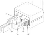
- FIG. 4illustrates in 3D perspective terminal leads in accordance with a first embodiment disclosed herein.
- FIG. 5illustrates in 3D perspective the terminal leads of FIG. 4 with addition of a retention feature.
- FIG. 6illustrates in 3D perspective the terminal leads of FIG. 4 with an addition of bus bars.
- FIG. 7illustrates in another 3D perspective the terminal leads of FIG. 4 with an addition of bus bars.
- FIG. 8illustrates terminal and bus bar current density for a terminal lead known from the prior art.
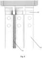
- FIG. 9illustrates terminal and bus bar current density for the terminal lead illustrated in FIG. 4 .
- FIG. 1illustrates in 3D perspective terminal leads 10 for a planar transformer as known from the prior art.
- the terminal leads 10are generally T-shaped with a first leg 12 and a second leg 14 off-set by 90°.
- the first leg 12is inserted into apertures 16 formed in the windings 18 .
- the windingsextend into an internal opening formed within a magnetic core 22 .
- the magnetic core 22is formed from a magnet material such as a ferrite optimized for power conversion and typically includes a central leg 25 extending through a centrally disposed aperture in the windings 18 .
- this leghas a cylindrical or rectangular cross-section.
- Bus bars 24electrically interconnect the terminal leads with a bolted connection.
- the second leg 14has a generally rectangular cross-section with relatively small surface area faces 26 adjacent one another.
- the regions of high current density near the edges of the parallel terminals and the interconnecting bus barsare regions of significantly elevated power loss.
- This proximity effectis illustrated in FIG. 3 .
- the proximity effectcauses current to crowd near the edges of a conductor when AC current is flowing in opposite directions.
- the proximity effectis most pronounced at high switching frequencies, nominally when the switching frequency exceeds 40 kHz and at high power levels, nominally, a power level in excess of 500 Watts.
- a current level of 100 Amps and a switch frequency of 100 kHzapproximately 70 percent of the current flow is concentrated along the edge 27 of the second leg 14 .
- FIG. 4illustrates in 3D perspective terminal leads in accordance with a first embodiment of the disclosure.
- the terminal leads 30are formed from an electrically conductive material, such as copper or a copper-base alloy. Instead of horizontally oriented terminals, the terminal leads 30 are vertically oriented.
- the vertically oriented terminal leads 30have relatively large surface area faces 32 adjacent one another.
- the vertically oriented terminal leads 30may be spaced close together or far apart, as dictated by the mechanical and performance requirements. Typically, for a high switch frequency, high power level application, the spacing between vertically oriented terminal leads is between 0.25 inch and 6 inches.
- High current capacity windings 34implemented as metal stampings, etchings or printed wiring boards, contain a notch 36 or groove to accept the vertically oriented terminal leads 30 .
- a notchmay be formed in the vertically oriented terminal leads 30 to accept an edge of the high current capacity windings.
- the vertically oriented terminal leads 30may be soldered, brazed, pressed, or otherwise electrically connected to the planar transformer windings.
- the notch 36 or groove contained in the windingsmay be a simple rectangular geometry, or a more complex geometry, such as a slotted retention feature 38 as shown in FIG. 5 to provide improved retention of the vertically oriented terminal leads 30 .
- This terminal arrangementhas multiple beneficial qualities. Proximity effects still have an influence on current distribution within the terminals, but now the flat surface area faces 32 of the terminal leads 30 and mating bus bars 40 are facing each other as shown in FIGS. 6 and 7 , allowing a higher fraction of the bus bar 40 cross sectional area to be utilized to carry current. Since the terminal leads 30 fit into a slot defined by notches 36 , the transformer windings 34 are allowed to move vertically during assembly, providing allowance for manufacturing variability. With the terminal connections centered on the stack of paralleled transformer windings 34 , the AC impedance is balanced, facilitating even current flow between windings. The same terminals may be used in multiple different designs, allowing modularity of design and a common building block approach.
- the terminal leads 30 disclosed hereinwere compared with prior art terminal leads in an exemplary design.
- the exemplary designwas a 7 kW rated planar transformer used in a switch mode power converter that produces 250 A of 28 VDC power. A switch frequency of 115 kHz was assumed.
- FIG. 8shows the 3D model of the planar transformer implemented using the prior art terminal leads 40 .
- FIG. 9shows the 3D model of a planar transformer of the same construction using the herein disclosed vertical terminals 30 . In each case, bus bars 24 were added to the planar transformer electromagnetic model that carried the output power 1.5 inches beyond the terminals, which is a typical distance required for connection to rectifiers rated for 250 A of current.
- FEMfinite element method
Landscapes
- Engineering & Computer Science (AREA)
- Power Engineering (AREA)
- Microelectronics & Electronic Packaging (AREA)
- Coils Or Transformers For Communication (AREA)
- Coils Of Transformers For General Uses (AREA)
Abstract
Description
| TABLE 1 | ||||
| Total | Transformer | |||
| Conduction | Losses in | Losses in | Winding | |
| Configuration | Loss | Terminals | Bus bars | Loss |
| T-Shaped Terminal | 28.32 W | 4.89 W | 13.49 W | 9.94 W |
| (Prior Art) | ||||
| Vertical Terminal | 12.68 W | 1.34 W | 3.59 W | 7.75 W |
| (Invention) | ||||
Claims (20)
Priority Applications (4)
| Application Number | Priority Date | Filing Date | Title |
|---|---|---|---|
| US15/972,511US11670448B2 (en) | 2018-05-07 | 2018-05-07 | System of termination of high power transformers for reduced AC termination loss at high frequency |
| PCT/US2019/029704WO2019217121A1 (en) | 2018-05-07 | 2019-04-29 | System of termination of high power transformers for reduced ac termination loss at high frequency |
| CA3095840ACA3095840C (en) | 2018-05-07 | 2019-04-29 | System of termination of high power transformers for reduced ac termination loss at high frequency |
| EP19799175.5AEP3785283B1 (en) | 2018-05-07 | 2019-04-29 | System of termination of high power transformers for reduced ac termination loss at high frequency |
Applications Claiming Priority (1)
| Application Number | Priority Date | Filing Date | Title |
|---|---|---|---|
| US15/972,511US11670448B2 (en) | 2018-05-07 | 2018-05-07 | System of termination of high power transformers for reduced AC termination loss at high frequency |
Publications (2)
| Publication Number | Publication Date |
|---|---|
| US20190341186A1 US20190341186A1 (en) | 2019-11-07 |
| US11670448B2true US11670448B2 (en) | 2023-06-06 |
Family
ID=68385154
Family Applications (1)
| Application Number | Title | Priority Date | Filing Date |
|---|---|---|---|
| US15/972,511Active2038-09-30US11670448B2 (en) | 2018-05-07 | 2018-05-07 | System of termination of high power transformers for reduced AC termination loss at high frequency |
Country Status (4)
| Country | Link |
|---|---|
| US (1) | US11670448B2 (en) |
| EP (1) | EP3785283B1 (en) |
| CA (1) | CA3095840C (en) |
| WO (1) | WO2019217121A1 (en) |
Families Citing this family (3)
| Publication number | Priority date | Publication date | Assignee | Title |
|---|---|---|---|---|
| US11990270B2 (en)* | 2020-11-23 | 2024-05-21 | Hyundai Mobis Co., Ltd. | Bus bar for minimizing AC loss in transformer and method of designing the same |
| KR20220085601A (en)* | 2020-12-15 | 2022-06-22 | 엘지이노텍 주식회사 | Electronic component module and Power Supply Unit having the same |
| CN114005660B (en)* | 2021-12-31 | 2022-04-05 | 上海电气集团(张家港)变压器有限公司 | Outgoing line structure of high-voltage winding of transformer and transformer |
Citations (54)
| Publication number | Priority date | Publication date | Assignee | Title |
|---|---|---|---|---|
| US2246167A (en)* | 1940-03-16 | 1941-06-17 | Gen Electric | Transformer |
| US2474395A (en)* | 1945-09-20 | 1949-06-28 | Gen Motors Corp | High-frequency transformer |
| US2535554A (en)* | 1949-01-24 | 1950-12-26 | Shell Dev | Close-coupled electrical transformer |
| US3465272A (en)* | 1967-12-01 | 1969-09-02 | Gen Electric | Internal bus connection for highcurrent ring - connected transformers and the like |
| US3916088A (en)* | 1973-02-19 | 1975-10-28 | Siemens Ag | Electric current supply lines for an induction heating coil used with a crucible-free melt zone apparatus |
| US4513273A (en)* | 1983-03-02 | 1985-04-23 | Lgz Landis & Gyr Zug Ag | Transducer for current measurement |
| US4835463A (en)* | 1987-08-24 | 1989-05-30 | Metricom, Inc. | Wide dynamic range a.c. current sensor |
| US4873757A (en)* | 1987-07-08 | 1989-10-17 | The Foxboro Company | Method of making a multilayer electrical coil |
| US5010314A (en) | 1990-03-30 | 1991-04-23 | Multisource Technology Corp. | Low-profile planar transformer for use in off-line switching power supplies |
| US5034717A (en)* | 1989-08-05 | 1991-07-23 | Mitsubishi Denki K.K. | Stationary electromagnetic induction unit |
| US5345670A (en)* | 1992-12-11 | 1994-09-13 | At&T Bell Laboratories | Method of making a surface-mount power magnetic device |
| US5559487A (en)* | 1994-05-10 | 1996-09-24 | Reltec Corporation | Winding construction for use in planar magnetic devices |
| US6046662A (en) | 1998-09-29 | 2000-04-04 | Compaq Computer Corporation | Low profile surface mount transformer |
| US6073339A (en) | 1996-09-20 | 2000-06-13 | Tdk Corporation Of America | Method of making low profile pin-less planar magnetic devices |
| US6114939A (en) | 1999-06-07 | 2000-09-05 | Technical Witts, Inc. | Planar stacked layer inductors and transformers |
| US6160467A (en)* | 1995-08-09 | 2000-12-12 | Visteon Global Technologies, Inc. | Transformer with center tap |
| US6335671B1 (en) | 1999-08-20 | 2002-01-01 | Tyco Electronics Logistics Ag | Surface mount circuit assembly |
| US6774755B2 (en)* | 1996-10-24 | 2004-08-10 | Matsushita Electric Industrial Co., Ltd. | Choke coil |
| US6882260B2 (en) | 2000-05-22 | 2005-04-19 | Payton Ltd. | Method and apparatus for insulating a planar transformer printed circuit and lead frame windings forms |
| US20050212640A1 (en) | 2004-03-24 | 2005-09-29 | Chiang Man-Ho | Multi-layer printed circuit board transformer winding |
| US20060082431A1 (en)* | 2004-10-14 | 2006-04-20 | Alexander Estrov | Surface mount magnetic component assembly |
| US7091817B2 (en)* | 2001-09-28 | 2006-08-15 | Delta Energy Systems (Switzerland) Ag | Planar transformer comprising plug-in secondary windings |
| US7248139B1 (en)* | 2006-01-30 | 2007-07-24 | Nemic-Lambda Ltd. | High-current electrical coil construction |
| US7277001B2 (en)* | 2004-08-20 | 2007-10-02 | Alps Electric Co., Ltd. | Coil-embedded dust core |
| US20080122569A1 (en)* | 2006-11-27 | 2008-05-29 | Delta Electronics, Inc. | Coil structure for high frequency transformer |
| US7460002B2 (en) | 2005-06-09 | 2008-12-02 | Alexander Estrov | Terminal system for planar magnetics assembly |
| US20090079528A1 (en) | 2007-09-25 | 2009-03-26 | Flextronics Ap, Llc | Thermally enhanced magnetic transformer |
| US7567164B2 (en)* | 2005-09-01 | 2009-07-28 | Artesyn Technologies, Inc. | Transformer having reduced size, safety insulation and low leakage inductance |
| US20090189726A1 (en)* | 2008-01-24 | 2009-07-30 | Abb Technology Ag | Dry-Type Transformer with Improved Terminal Construction and Mounting System Therefor |
| US20090302986A1 (en)* | 2008-06-10 | 2009-12-10 | Bedea Tiberiu A | Minimal-length windings for reduction of copper power losses in magnetic elements |
| US20090315660A1 (en)* | 2006-03-20 | 2009-12-24 | Sumida Corporation | Inductor |
| US20100265029A1 (en) | 2009-04-17 | 2010-10-21 | Delta Electronics, Inc. | Winding structure for a transformer and winding |
| US20100271161A1 (en)* | 2008-07-11 | 2010-10-28 | Yipeng Yan | Magnetic components and methods of manufacturing the same |
| US20110148559A1 (en)* | 2009-12-21 | 2011-06-23 | Alexandr Ikriannikov | multi-turn inductors |
| US8013709B2 (en) | 2008-04-18 | 2011-09-06 | Delta Electronics, Inc. | Conductive module and assembly structure having such conductive module |
| EP2523198A1 (en) | 2011-05-12 | 2012-11-14 | SUMIDA Components & Modules GmbH | Transformer with laminated coil |
| JP2013012317A (en)* | 2011-06-28 | 2013-01-17 | Mitsuba Corp | Electromagnetic relay |
| US20130106557A1 (en)* | 2011-10-31 | 2013-05-02 | Delta Electronics (Shanghai) Co., Ltd. | Integrated magnetic element |
| US8471665B2 (en)* | 2011-07-25 | 2013-06-25 | Sumida Corporation | Magnetic element |
| US20130194061A1 (en) | 2012-02-01 | 2013-08-01 | Delta Electronics, Inc. | Magnetic module and base thereof |
| JP2013218882A (en)* | 2012-04-09 | 2013-10-24 | Omron Corp | Coil terminal |
| CN203706831U (en) | 2014-02-19 | 2014-07-09 | 艾默生网络能源有限公司 | Planar transformer |
| US8841984B1 (en) | 2012-01-30 | 2014-09-23 | Rockwell Collins, Inc. | Planar transformer with imbalanced copper thickness |
| US8896406B2 (en)* | 2011-09-16 | 2014-11-25 | Hitachi Metals, Ltd. | Laminated coil |
| CN204011288U (en)* | 2014-07-18 | 2014-12-10 | 厦门宏发电声股份有限公司 | A kind of coil weld tabs and double-wound relay thereof |
| US20150221431A1 (en)* | 2014-02-05 | 2015-08-06 | Wen-Hsiang Wu Li | Modularized planar coil layer and planar transformer using the same |
| US9105390B2 (en)* | 2013-03-13 | 2015-08-11 | Yujing Technology Co., Ltd. | Structure of transformer |
| US9142345B2 (en)* | 2014-01-17 | 2015-09-22 | Delta Electronics, Inc. | Bent conduction sheet member, covering member and conductive winding assembly combining same |
| US9305696B2 (en)* | 2014-07-08 | 2016-04-05 | Alliance Magnetics (H.K.) Co. Ltd. | Stacked inductor |
| US9378885B2 (en) | 2012-03-27 | 2016-06-28 | Pulse Electronics, Inc. | Flat coil windings, and inductive devices and electronics assemblies that utilize flat coil windings |
| US20170032888A1 (en)* | 2015-07-31 | 2017-02-02 | Solum Co., Ltd. | Transformer and plate coil molded body |
| US20170117090A1 (en)* | 2015-10-27 | 2017-04-27 | Chicony Power Technology Co., Ltd. | Energy storage apparatus |
| US20170366093A1 (en) | 2016-06-21 | 2017-12-21 | Astronics Advanced Electronic Systems Corp. | Regulating transformer rectifier unit for dc power applications |
| US10062496B2 (en)* | 2015-02-26 | 2018-08-28 | Lear Corporation | Planar transformer |
- 2018
- 2018-05-07USUS15/972,511patent/US11670448B2/enactiveActive
- 2019
- 2019-04-29EPEP19799175.5Apatent/EP3785283B1/enactiveActive
- 2019-04-29WOPCT/US2019/029704patent/WO2019217121A1/ennot_activeCeased
- 2019-04-29CACA3095840Apatent/CA3095840C/enactiveActive
Patent Citations (55)
| Publication number | Priority date | Publication date | Assignee | Title |
|---|---|---|---|---|
| US2246167A (en)* | 1940-03-16 | 1941-06-17 | Gen Electric | Transformer |
| US2474395A (en)* | 1945-09-20 | 1949-06-28 | Gen Motors Corp | High-frequency transformer |
| US2535554A (en)* | 1949-01-24 | 1950-12-26 | Shell Dev | Close-coupled electrical transformer |
| US3465272A (en)* | 1967-12-01 | 1969-09-02 | Gen Electric | Internal bus connection for highcurrent ring - connected transformers and the like |
| US3916088A (en)* | 1973-02-19 | 1975-10-28 | Siemens Ag | Electric current supply lines for an induction heating coil used with a crucible-free melt zone apparatus |
| US4513273A (en)* | 1983-03-02 | 1985-04-23 | Lgz Landis & Gyr Zug Ag | Transducer for current measurement |
| US4873757A (en)* | 1987-07-08 | 1989-10-17 | The Foxboro Company | Method of making a multilayer electrical coil |
| US4835463A (en)* | 1987-08-24 | 1989-05-30 | Metricom, Inc. | Wide dynamic range a.c. current sensor |
| US5034717A (en)* | 1989-08-05 | 1991-07-23 | Mitsubishi Denki K.K. | Stationary electromagnetic induction unit |
| US5010314A (en) | 1990-03-30 | 1991-04-23 | Multisource Technology Corp. | Low-profile planar transformer for use in off-line switching power supplies |
| US5345670A (en)* | 1992-12-11 | 1994-09-13 | At&T Bell Laboratories | Method of making a surface-mount power magnetic device |
| US5559487A (en)* | 1994-05-10 | 1996-09-24 | Reltec Corporation | Winding construction for use in planar magnetic devices |
| US6160467A (en)* | 1995-08-09 | 2000-12-12 | Visteon Global Technologies, Inc. | Transformer with center tap |
| US6073339A (en) | 1996-09-20 | 2000-06-13 | Tdk Corporation Of America | Method of making low profile pin-less planar magnetic devices |
| US6774755B2 (en)* | 1996-10-24 | 2004-08-10 | Matsushita Electric Industrial Co., Ltd. | Choke coil |
| US6046662A (en) | 1998-09-29 | 2000-04-04 | Compaq Computer Corporation | Low profile surface mount transformer |
| US6114939A (en) | 1999-06-07 | 2000-09-05 | Technical Witts, Inc. | Planar stacked layer inductors and transformers |
| US6335671B1 (en) | 1999-08-20 | 2002-01-01 | Tyco Electronics Logistics Ag | Surface mount circuit assembly |
| US6882260B2 (en) | 2000-05-22 | 2005-04-19 | Payton Ltd. | Method and apparatus for insulating a planar transformer printed circuit and lead frame windings forms |
| US7091817B2 (en)* | 2001-09-28 | 2006-08-15 | Delta Energy Systems (Switzerland) Ag | Planar transformer comprising plug-in secondary windings |
| US20050212640A1 (en) | 2004-03-24 | 2005-09-29 | Chiang Man-Ho | Multi-layer printed circuit board transformer winding |
| US7277001B2 (en)* | 2004-08-20 | 2007-10-02 | Alps Electric Co., Ltd. | Coil-embedded dust core |
| US20060082431A1 (en)* | 2004-10-14 | 2006-04-20 | Alexander Estrov | Surface mount magnetic component assembly |
| US7460002B2 (en) | 2005-06-09 | 2008-12-02 | Alexander Estrov | Terminal system for planar magnetics assembly |
| US7567164B2 (en)* | 2005-09-01 | 2009-07-28 | Artesyn Technologies, Inc. | Transformer having reduced size, safety insulation and low leakage inductance |
| US7248139B1 (en)* | 2006-01-30 | 2007-07-24 | Nemic-Lambda Ltd. | High-current electrical coil construction |
| US20090315660A1 (en)* | 2006-03-20 | 2009-12-24 | Sumida Corporation | Inductor |
| US20080122569A1 (en)* | 2006-11-27 | 2008-05-29 | Delta Electronics, Inc. | Coil structure for high frequency transformer |
| US20090079528A1 (en) | 2007-09-25 | 2009-03-26 | Flextronics Ap, Llc | Thermally enhanced magnetic transformer |
| US20090189726A1 (en)* | 2008-01-24 | 2009-07-30 | Abb Technology Ag | Dry-Type Transformer with Improved Terminal Construction and Mounting System Therefor |
| US8013709B2 (en) | 2008-04-18 | 2011-09-06 | Delta Electronics, Inc. | Conductive module and assembly structure having such conductive module |
| US20090302986A1 (en)* | 2008-06-10 | 2009-12-10 | Bedea Tiberiu A | Minimal-length windings for reduction of copper power losses in magnetic elements |
| US20100271161A1 (en)* | 2008-07-11 | 2010-10-28 | Yipeng Yan | Magnetic components and methods of manufacturing the same |
| US20100265029A1 (en) | 2009-04-17 | 2010-10-21 | Delta Electronics, Inc. | Winding structure for a transformer and winding |
| US20110148559A1 (en)* | 2009-12-21 | 2011-06-23 | Alexandr Ikriannikov | multi-turn inductors |
| EP2523198A1 (en) | 2011-05-12 | 2012-11-14 | SUMIDA Components & Modules GmbH | Transformer with laminated coil |
| JP2013012317A (en)* | 2011-06-28 | 2013-01-17 | Mitsuba Corp | Electromagnetic relay |
| US8471665B2 (en)* | 2011-07-25 | 2013-06-25 | Sumida Corporation | Magnetic element |
| US8896406B2 (en)* | 2011-09-16 | 2014-11-25 | Hitachi Metals, Ltd. | Laminated coil |
| US20130106557A1 (en)* | 2011-10-31 | 2013-05-02 | Delta Electronics (Shanghai) Co., Ltd. | Integrated magnetic element |
| US8841984B1 (en) | 2012-01-30 | 2014-09-23 | Rockwell Collins, Inc. | Planar transformer with imbalanced copper thickness |
| US20130194061A1 (en) | 2012-02-01 | 2013-08-01 | Delta Electronics, Inc. | Magnetic module and base thereof |
| US9129734B2 (en)* | 2012-02-01 | 2015-09-08 | Delta Electronics, Inc. | Magnetic module and base thereof |
| US9378885B2 (en) | 2012-03-27 | 2016-06-28 | Pulse Electronics, Inc. | Flat coil windings, and inductive devices and electronics assemblies that utilize flat coil windings |
| JP2013218882A (en)* | 2012-04-09 | 2013-10-24 | Omron Corp | Coil terminal |
| US9105390B2 (en)* | 2013-03-13 | 2015-08-11 | Yujing Technology Co., Ltd. | Structure of transformer |
| US9142345B2 (en)* | 2014-01-17 | 2015-09-22 | Delta Electronics, Inc. | Bent conduction sheet member, covering member and conductive winding assembly combining same |
| US20150221431A1 (en)* | 2014-02-05 | 2015-08-06 | Wen-Hsiang Wu Li | Modularized planar coil layer and planar transformer using the same |
| CN203706831U (en) | 2014-02-19 | 2014-07-09 | 艾默生网络能源有限公司 | Planar transformer |
| US9305696B2 (en)* | 2014-07-08 | 2016-04-05 | Alliance Magnetics (H.K.) Co. Ltd. | Stacked inductor |
| CN204011288U (en)* | 2014-07-18 | 2014-12-10 | 厦门宏发电声股份有限公司 | A kind of coil weld tabs and double-wound relay thereof |
| US10062496B2 (en)* | 2015-02-26 | 2018-08-28 | Lear Corporation | Planar transformer |
| US20170032888A1 (en)* | 2015-07-31 | 2017-02-02 | Solum Co., Ltd. | Transformer and plate coil molded body |
| US20170117090A1 (en)* | 2015-10-27 | 2017-04-27 | Chicony Power Technology Co., Ltd. | Energy storage apparatus |
| US20170366093A1 (en) | 2016-06-21 | 2017-12-21 | Astronics Advanced Electronic Systems Corp. | Regulating transformer rectifier unit for dc power applications |
Non-Patent Citations (2)
| Title |
|---|
| European Patent Office; EP 19799175.5; Extended European Search Report; dated Jan. 7, 2022. |
| WIPO, PCT/US2019/029704; International Search Report; dated Jul. 10, 2019. |
Also Published As
| Publication number | Publication date |
|---|---|
| US20190341186A1 (en) | 2019-11-07 |
| CA3095840C (en) | 2024-01-09 |
| EP3785283A1 (en) | 2021-03-03 |
| EP3785283A4 (en) | 2022-01-26 |
| CA3095840A1 (en) | 2019-11-14 |
| EP3785283B1 (en) | 2025-06-04 |
| WO2019217121A1 (en) | 2019-11-14 |
Similar Documents
| Publication | Publication Date | Title |
|---|---|---|
| US11670448B2 (en) | System of termination of high power transformers for reduced AC termination loss at high frequency | |
| US7952025B2 (en) | Switchboard bus assembly in which material requirements are reduced without reducing performance | |
| US7460002B2 (en) | Terminal system for planar magnetics assembly | |
| US20170345756A1 (en) | Power module and power device | |
| EP2559039B1 (en) | Integral planar transformer and busbar | |
| US5929734A (en) | Coil former for a flat coil | |
| US20090102593A1 (en) | Coil form | |
| EP3545538B1 (en) | Capacitor, particularly intermediate circuit capacitor for a multiphase system | |
| CN111490419B (en) | Power connector for busbar | |
| US20140342585A1 (en) | Bus bar for electrical power distribution | |
| DE112018002547T5 (en) | circuit device | |
| DE112017003113B4 (en) | Isolated converter | |
| RU2388092C2 (en) | Pulse transformer with foil winding | |
| US5013265A (en) | Connector for mating blade-shaped members | |
| US9019059B2 (en) | Multi-turn high density coil and fabrication method | |
| CN114158221B (en) | Synchronous rectification module | |
| US10389266B2 (en) | Rectification module | |
| EP0936637A2 (en) | Transformator | |
| CN106921097B (en) | Busbar and preparation method thereof | |
| US20220301760A1 (en) | Transformer | |
| CN201037851Y (en) | Multi-polarity power inductor | |
| US4466678A (en) | Mount for high-amp miniature relay on a printed-circuit board | |
| CN109887645B (en) | Conductive busbar | |
| CN113544805A (en) | Integrated transformer with low alternating current loss and impedance balance interface | |
| CN106971867B (en) | Moving contact and circuit breaker |
Legal Events
| Date | Code | Title | Description |
|---|---|---|---|
| AS | Assignment | Owner name:ASTRONICS ADVANCED ELECTRONIC SYSTEMS CORP., WASHINGTON Free format text:ASSIGNMENT OF ASSIGNORS INTEREST;ASSIGNOR:WAMBSGANSS, WARREN J.;REEL/FRAME:045732/0094 Effective date:20180507 Owner name:ASTRONICS ADVANCED ELECTRONIC SYSTEMS CORP., WASHI Free format text:ASSIGNMENT OF ASSIGNORS INTEREST;ASSIGNOR:WAMBSGANSS, WARREN J.;REEL/FRAME:045732/0094 Effective date:20180507 | |
| FEPP | Fee payment procedure | Free format text:ENTITY STATUS SET TO UNDISCOUNTED (ORIGINAL EVENT CODE: BIG.); ENTITY STATUS OF PATENT OWNER: LARGE ENTITY | |
| STPP | Information on status: patent application and granting procedure in general | Free format text:NON FINAL ACTION MAILED | |
| STPP | Information on status: patent application and granting procedure in general | Free format text:FINAL REJECTION MAILED | |
| STPP | Information on status: patent application and granting procedure in general | Free format text:RESPONSE AFTER FINAL ACTION FORWARDED TO EXAMINER | |
| STPP | Information on status: patent application and granting procedure in general | Free format text:ADVISORY ACTION MAILED | |
| STPP | Information on status: patent application and granting procedure in general | Free format text:DOCKETED NEW CASE - READY FOR EXAMINATION | |
| STPP | Information on status: patent application and granting procedure in general | Free format text:NON FINAL ACTION MAILED | |
| STPP | Information on status: patent application and granting procedure in general | Free format text:RESPONSE TO NON-FINAL OFFICE ACTION ENTERED AND FORWARDED TO EXAMINER | |
| STPP | Information on status: patent application and granting procedure in general | Free format text:FINAL REJECTION MAILED | |
| STPP | Information on status: patent application and granting procedure in general | Free format text:DOCKETED NEW CASE - READY FOR EXAMINATION | |
| STPP | Information on status: patent application and granting procedure in general | Free format text:NON FINAL ACTION MAILED | |
| STPP | Information on status: patent application and granting procedure in general | Free format text:RESPONSE TO NON-FINAL OFFICE ACTION ENTERED AND FORWARDED TO EXAMINER | |
| AS | Assignment | Owner name:HSBC BANK USA, NATIONAL ASSOCIATION, AS AGENT, NEW YORK Free format text:SECURITY INTEREST;ASSIGNORS:ASTRONICS AEROSTAT CORPORATION;ASTRONICS CONNECTIVITY SYSTEMS & CERTIFICATION CORP.;ASTRONICS CORPORATION;AND OTHERS;REEL/FRAME:062445/0342 Effective date:20230119 Owner name:GREAT ROCK CAPITAL MANAGEMENT, LLC, CONNECTICUT Free format text:SECURITY INTEREST;ASSIGNORS:ASTRONICS CUSTOM CONTROL CONCEPTS INC.;ASTRONICS DME LLC;ASTRONICS CORPORATION;AND OTHERS;REEL/FRAME:062444/0836 Effective date:20230119 | |
| STCF | Information on status: patent grant | Free format text:PATENTED CASE | |
| AS | Assignment | Owner name:HSBC BANK USA, N.A., NEW YORK Free format text:SECURITY INTEREST;ASSIGNORS:ASTRONICS CORPORATION;ASTRONICS ADVANCED ELECTRONIC SYSTEMS CORP.;ASTRONICS AEROSAT CORPORATION;AND OTHERS;REEL/FRAME:068283/0900 Effective date:20240711 | |
| AS | Assignment | Owner name:LUMINESCENT SYSTEMS, INC., NEW YORK Free format text:RELEASE BY SECURED PARTY;ASSIGNOR:GREAT ROCK CAPITAL PARTNERS MANAGEMENT, LLC;REEL/FRAME:067977/0291 Effective date:20240711 Owner name:DIAGNOSYS INC., FLORIDA Free format text:RELEASE BY SECURED PARTY;ASSIGNOR:GREAT ROCK CAPITAL PARTNERS MANAGEMENT, LLC;REEL/FRAME:067977/0291 Effective date:20240711 Owner name:ASTRONICS TEST SYSTEMS INC., FLORIDA Free format text:RELEASE BY SECURED PARTY;ASSIGNOR:GREAT ROCK CAPITAL PARTNERS MANAGEMENT, LLC;REEL/FRAME:067977/0291 Effective date:20240711 Owner name:ASTRONICS CORPORATION, NEW YORK Free format text:RELEASE BY SECURED PARTY;ASSIGNOR:GREAT ROCK CAPITAL PARTNERS MANAGEMENT, LLC;REEL/FRAME:067977/0291 Effective date:20240711 Owner name:ASTRONICS ADVANCED ELECTRONIC SYSTEMS CORP., WASHINGTON Free format text:RELEASE BY SECURED PARTY;ASSIGNOR:GREAT ROCK CAPITAL PARTNERS MANAGEMENT, LLC;REEL/FRAME:067977/0291 Effective date:20240711 Owner name:PECO, INC., OREGON Free format text:RELEASE BY SECURED PARTY;ASSIGNOR:GREAT ROCK CAPITAL PARTNERS MANAGEMENT, LLC;REEL/FRAME:067977/0291 Effective date:20240711 Owner name:ASTRONICS CONNECTIVITY SYSTEMS & CERTIFICATION CORP., ILLINOIS Free format text:RELEASE BY SECURED PARTY;ASSIGNOR:GREAT ROCK CAPITAL PARTNERS MANAGEMENT, LLC;REEL/FRAME:067977/0291 Effective date:20240711 Owner name:ASTRONICS AEROSAT CORPORATION, NEW HAMPSHIRE Free format text:RELEASE BY SECURED PARTY;ASSIGNOR:GREAT ROCK CAPITAL PARTNERS MANAGEMENT, LLC;REEL/FRAME:067977/0291 Effective date:20240711 | |
| AS | Assignment | Owner name:HSBC BANK USA, NATIONAL ASSOCIATION, AS AGENT, NEW YORK Free format text:SECURITY INTEREST;ASSIGNORS:ASTRONICS ASEROSTAT CORPORATION;ASTRONICS ADVANCED ELECTRONIC SYSTEMS CORP.;ASTRONICS TEST SYSTEMS INC.;REEL/FRAME:068478/0769 Effective date:20240711 | |
| AS | Assignment | Owner name:DIAGNOSYS INC., MASSACHUSETTS Free format text:RELEASE BY SECURED PARTY;ASSIGNOR:HSBC BANK USA, N.A., AS AGENT;REEL/FRAME:069491/0184 Effective date:20241203 Owner name:PECO, INC., OREGON Free format text:RELEASE BY SECURED PARTY;ASSIGNOR:HSBC BANK USA, N.A., AS AGENT;REEL/FRAME:069491/0184 Effective date:20241203 Owner name:ASTRONICS CONNECTIVITY SYSTEMS & CERTIFICATION CORP., NEW YORK Free format text:RELEASE BY SECURED PARTY;ASSIGNOR:HSBC BANK USA, N.A., AS AGENT;REEL/FRAME:069491/0184 Effective date:20241203 Owner name:LUMINESCENT SYSTEMS, INC., NEW YORK Free format text:RELEASE BY SECURED PARTY;ASSIGNOR:HSBC BANK USA, N.A., AS AGENT;REEL/FRAME:069491/0184 Effective date:20241203 Owner name:ASTRONICS TEST SYSTEMS INC., CALIFORNIA Free format text:RELEASE BY SECURED PARTY;ASSIGNOR:HSBC BANK USA, N.A., AS AGENT;REEL/FRAME:069491/0184 Effective date:20241203 Owner name:ASTRONICS AEROSAT CORPORATION, NEW HAMPSHIRE Free format text:RELEASE BY SECURED PARTY;ASSIGNOR:HSBC BANK USA, N.A., AS AGENT;REEL/FRAME:069491/0184 Effective date:20241203 Owner name:ASTRONICS ADVANCED ELECTRONIC SYSTEMS CORP., WASHINGTON Free format text:RELEASE BY SECURED PARTY;ASSIGNOR:HSBC BANK USA, N.A., AS AGENT;REEL/FRAME:069491/0184 Effective date:20241203 Owner name:ASTRONICS CORPORATION, NEW YORK Free format text:RELEASE BY SECURED PARTY;ASSIGNOR:HSBC BANK USA, N.A., AS AGENT;REEL/FRAME:069491/0184 Effective date:20241203 |