US11665493B2 - Acoustic sealing analysis system - Google Patents
Acoustic sealing analysis systemDownload PDFInfo
- Publication number
- US11665493B2 US11665493B2US17/182,570US202117182570AUS11665493B2US 11665493 B2US11665493 B2US 11665493B2US 202117182570 AUS202117182570 AUS 202117182570AUS 11665493 B2US11665493 B2US 11665493B2
- Authority
- US
- United States
- Prior art keywords
- signal
- audio device
- microphone
- acoustic
- test signal
- Prior art date
- Legal status (The legal status is an assumption and is not a legal conclusion. Google has not performed a legal analysis and makes no representation as to the accuracy of the status listed.)
- Active, expires
Links
Images


Classifications
- H—ELECTRICITY
- H04—ELECTRIC COMMUNICATION TECHNIQUE
- H04R—LOUDSPEAKERS, MICROPHONES, GRAMOPHONE PICK-UPS OR LIKE ACOUSTIC ELECTROMECHANICAL TRANSDUCERS; DEAF-AID SETS; PUBLIC ADDRESS SYSTEMS
- H04R29/00—Monitoring arrangements; Testing arrangements
- H04R29/001—Monitoring arrangements; Testing arrangements for loudspeakers
- H—ELECTRICITY
- H04—ELECTRIC COMMUNICATION TECHNIQUE
- H04R—LOUDSPEAKERS, MICROPHONES, GRAMOPHONE PICK-UPS OR LIKE ACOUSTIC ELECTROMECHANICAL TRANSDUCERS; DEAF-AID SETS; PUBLIC ADDRESS SYSTEMS
- H04R25/00—Deaf-aid sets, i.e. electro-acoustic or electro-mechanical hearing aids; Electric tinnitus maskers providing an auditory perception
- H04R25/70—Adaptation of deaf aid to hearing loss, e.g. initial electronic fitting
- H—ELECTRICITY
- H04—ELECTRIC COMMUNICATION TECHNIQUE
- H04R—LOUDSPEAKERS, MICROPHONES, GRAMOPHONE PICK-UPS OR LIKE ACOUSTIC ELECTROMECHANICAL TRANSDUCERS; DEAF-AID SETS; PUBLIC ADDRESS SYSTEMS
- H04R1/00—Details of transducers, loudspeakers or microphones
- H04R1/10—Earpieces; Attachments therefor ; Earphones; Monophonic headphones
- H04R1/1016—Earpieces of the intra-aural type
- H—ELECTRICITY
- H04—ELECTRIC COMMUNICATION TECHNIQUE
- H04R—LOUDSPEAKERS, MICROPHONES, GRAMOPHONE PICK-UPS OR LIKE ACOUSTIC ELECTROMECHANICAL TRANSDUCERS; DEAF-AID SETS; PUBLIC ADDRESS SYSTEMS
- H04R1/00—Details of transducers, loudspeakers or microphones
- H04R1/10—Earpieces; Attachments therefor ; Earphones; Monophonic headphones
- H04R1/1091—Details not provided for in groups H04R1/1008 - H04R1/1083
- H—ELECTRICITY
- H04—ELECTRIC COMMUNICATION TECHNIQUE
- H04R—LOUDSPEAKERS, MICROPHONES, GRAMOPHONE PICK-UPS OR LIKE ACOUSTIC ELECTROMECHANICAL TRANSDUCERS; DEAF-AID SETS; PUBLIC ADDRESS SYSTEMS
- H04R29/00—Monitoring arrangements; Testing arrangements
- H—ELECTRICITY
- H04—ELECTRIC COMMUNICATION TECHNIQUE
- H04R—LOUDSPEAKERS, MICROPHONES, GRAMOPHONE PICK-UPS OR LIKE ACOUSTIC ELECTROMECHANICAL TRANSDUCERS; DEAF-AID SETS; PUBLIC ADDRESS SYSTEMS
- H04R2460/00—Details of hearing devices, i.e. of ear- or headphones covered by H04R1/10 or H04R5/033 but not provided for in any of their subgroups, or of hearing aids covered by H04R25/00 but not provided for in any of its subgroups
- H04R2460/07—Use of position data from wide-area or local-area positioning systems in hearing devices, e.g. program or information selection
- H—ELECTRICITY
- H04—ELECTRIC COMMUNICATION TECHNIQUE
- H04R—LOUDSPEAKERS, MICROPHONES, GRAMOPHONE PICK-UPS OR LIKE ACOUSTIC ELECTROMECHANICAL TRANSDUCERS; DEAF-AID SETS; PUBLIC ADDRESS SYSTEMS
- H04R2460/00—Details of hearing devices, i.e. of ear- or headphones covered by H04R1/10 or H04R5/033 but not provided for in any of their subgroups, or of hearing aids covered by H04R25/00 but not provided for in any of its subgroups
- H04R2460/15—Determination of the acoustic seal of ear moulds or ear tips of hearing devices
Definitions
- the present inventionrelates to testing the seal of an orifice-inserted device, and more particularly, though not exclusively, to a device and method for determining if an earpiece is sealed correctly in an ear canal.
- one method to prevent ambient sound from entering the earis to seal or provide an acoustic barrier at the opening of the ear canal. Sealing minimizes ambient sound leakage into the ear canal, and under the correct conditions can provide a level of noise suppression under high background noise conditions.
- Certain types of acoustic softwaree.g., communication in a noisy environment via an ear canal microphone
- user conditionsmay change substantially during the operation of the earpiece, and in some circumstances, the earpiece may become misaligned or may be fit incorrectly such that it is not sealed correctly.
- a method of seal detectionis needed to optimize performance.
- embodimentsare directed to a device and method to determine if an earpiece is sealing within the design specification of the device.
- the devicecan include a sealing section forming an acoustic barrier between a first volume and a second volume.
- An ear canal receiver (ECR)can be configured to generate an acoustic signal in the first volume.
- An Ear Canal Microphone (ECM) in the first volumecan be configured to measure the acoustic signal in the first volume.
- the first acoustic signal emitted by the ECRcan be cross-correlated with the first acoustic signal detected with the ECM to determine if the sealing section is sealed properly.
- At least one exemplary embodimentis directed to a method of detecting sealing integrity of an earpiece comprising the steps of: providing a test signal; generating an acoustic signal corresponding to the test signal incident on an ear canal side of a sealing section; converting the acoustic signal incident on a first side of the sealing section to an electrical signal; and cross-correlating the test signal to the electrical signal where the earpiece is sealed correctly when a cross-correlation between the test signal and the electrical signal is above a threshold.
- At least one exemplary embodimentis directed to a method of adjusting attenuation of an earpiece comprising the steps of: relating cross-correlation of a test signal and a measured acoustic signal in an ear canal of a user to an attenuation level of a sealing section of the earpiece; comparing the attenuation level of the sealing section of the earpiece to a minimum attenuation value; and adjusting a pressure of the sealing section to meet the minimum attenuation value.
- At least one exemplary embodimentis directed to a device comprising: a sealing section configured to seal a user's orifice, where the sealing section is configured to produce an acoustic seal between a first side of the sealing section and a second side of the sealing section; a transducer configured to generate a first acoustic signal incident on the first side of the sealing section; and a first microphone configured to measure a second acoustic signal incident on the second side of the sealing section, where the second acoustic signal includes at least a portion of the first acoustic signal that has passed from the first side to the second side of the sealing section where the first acoustic signal is compared to the second acoustic signal to determine if the sealing section is sealed.
- FIG. 1is a diagram of an earpiece inserted in an ear canal in accordance with an exemplary embodiment
- FIG. 2is a block diagram of optional components of an earpiece in accordance with an exemplary embodiment
- FIG. 3is a flowchart of a method for checking an ear seal in accordance with an exemplary embodiment
- FIG. 4is a flowchart to determine acoustic seal integrity of an earpiece in accordance with the exemplary embodiment.
- FIG. 5is a flowchart of a method to estimate the instantaneous cross-correlation between a first and second audio signal.
- FIG. 6is a flowchart to determine when to emit a test signal in accordance with an exemplary embodiment
- FIG. 7is a graph illustrating different seal measurements in accordance with the present invention.
- FIG. 8is a block diagram for a method of adjusting the IMS system in accordance with at least one exemplary embodiment
- FIG. 9is a block diagram for a method of adjusting IMS pressure in accordance with at least one exemplary embodiment
- FIG. 10illustrates a sample relationship between EarSeal attenuation and XCorr in accordance with at least one exemplary embodiment
- FIG. 11illustrates a flowchart of an exemplary method to determine a test signal fundamental
- FIG. 12illustrates a flowchart of an exemplary embodiment to determine tonal presence in audio content
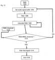
- FIG. 13illustrates a flowchart of a method to determine when to emit the test signal
- FIG. 14illustrates a flowchart of an exemplary method to determine acoustic seal integrity
- FIGS. 15 A and 15 Billustrate a method of varying the seal of an inflation system in accordance with at least one exemplary embodiment
- Exemplary embodimentsare directed to or can be operatively used on various wired or wireless orifice inserted devices for example earpiece devices (e.g., earbuds, headphones, ear terminals, behind the ear devices or other acoustic devices as known by one of ordinary skill, and equivalents).
- earpiece devicese.g., earbuds, headphones, ear terminals, behind the ear devices or other acoustic devices as known by one of ordinary skill, and equivalents.
- exemplary embodimentsare not limited to earpieces, for example some functionality can be implemented on other systems with speakers and/or microphones for example computer systems, PDAs, BlackBerry® smart phones, cell and mobile phones, and any other device that emits or measures acoustic energy. Additionally, exemplary embodiments can be used with digital and non-digital acoustic systems. Additionally various receivers and microphones can be used, for example MEMs transducers, diaphragm transducers, for example Knowles' FG and EG series transducers.
- any specific valuesfor example the sound pressure level change, should be interpreted to be illustrative only and non-limiting. Thus, other examples of the exemplary embodiments could have different values.
- FIG. 1is a diagram of an earpiece inserted in an ear canal 124 in accordance with at least one exemplary embodiment of the invention.
- FIG. 1also illustrates portions of the ear including pinna 128 , ear canal 124 and eardrum 126 .
- the earpiececomprises an electronic housing unit 100 and a sealing unit 108 .
- the earpiecedepicts an electro-acoustical assembly for an in-the-ear acoustic assembly, as it would typically be placed in an ear canal 124 of a user 130 .
- the earpieceis an in-ear earpiece, behind the ear earpiece, receiver in the ear, partial-fit device, or any other suitable earpiece type.
- the earpiececan partially or fully occlude the ear canal 124 .
- the earpieceincludes an Ambient Sound Microphone (ASM) 120 to capture ambient sound, an Ear Canal Receiver (ECR) 114 to deliver audio to an ear canal 124 , and an Ear Canal Microphone (ECM) 106 to capture and assess a sound exposure level within the ear canal 124 .
- the earpiececan partially or fully occlude the ear canal 124 to provide various degrees of acoustic isolation.
- the assemblyis designed to be inserted into the user's ear canal 124 , and to form an acoustic seal with the walls of the ear canal 124 at a location between the entrance to the ear canal 124 and the tympanic membrane (or ear drum) 126 . In general, such a seal is typically achieved by means of a soft and compliant housing of the sealing unit 108 . Additionally, the sealing unit 108 can be a pressurized expandable element that fills a portion of the available local space.
- Sealing unit 108is an acoustic barrier having a first side corresponding to ear canal 124 and a second side corresponding to the ambient environment.
- sealing unit 108includes an ear canal microphone tube 110 and an ear canal receiver tube 112 .
- Sealing unit 108creates a closed cavity of approximately 5 cc or less between the first side of sealing unit 108 and the tympanic membrane 126 in ear canal 124 .
- the sealingfacilitates using the ECR (speaker) 114 to generate a full range bass response when reproducing sounds for the user.
- This sealalso serves to significantly reduce the sound pressure level at the user's eardrum 126 resulting from the sound field at the entrance to the ear canal 124 .
- This sealis also a basis for a sound isolating performance of the electro-acoustic assembly.
- the second side of sealing unit 108corresponds to the side adjacent to electronic housing unit 100 .
- Ambient sound microphone 120is housed in electronic housing unit 100 and is exposed to the ambient environment for receiving sound from the ambient environment around the user.
- the electronic housing unit 100can include various system components such as a microprocessor 116 , memory 104 , battery 102 , ECM 106 , ASM 120 , ECR, 114 , and user interface 122 , or these components can reside in a separate system or interface operatively connected.
- Microprocessor 116(or processor 116 ) can be a logic circuit, a digital signal processor, controller, or the like for performing calculations and operations for the earpiece.
- Microprocessor 116is operatively coupled to memory 104 , ECM 106 , ASM 120 , ECR 114 , and user interface 122 .
- An optional wire 118can provide an external connection to the earpiece.
- Battery 102powers the circuits and transducers of the earpiece.
- Battery 102can be a rechargeable or replaceable battery.
- electronic housing unit 100is adjacent to sealing unit 108 . Openings in electronic housing unit 100 receive ECM tube 110 and ECR tube 112 to respectively couple to ECM 106 and ECR 114 .
- ECR tube 112 and ECM tube 110acoustically couple signals to and from ear canal 124 .
- ECR 114outputs an acoustic signal through ECR tube 112 and into ear canal 124 where it is received by the tympanic membrane 126 of the user of the earpiece.
- ECM 106receives an acoustic signal present in ear canal 124 though ECM tube 110 .
- ECM 106One function of ECM 106 is that of measuring the sound pressure level in the ear canal cavity 124 as a part of testing the hearing acuity of the user as well as confirming the integrity of the acoustic seal and the working condition of the earpiece.
- ASM 120is used to monitor sound pressure at the entrance to the occluded or partially occluded ear canal 124 . All transducers shown can receive or transmit audio signals to a processor 116 that undertakes audio signal processing and provides a transceiver for audio via the wired (wire 118 ) or a wireless communication path. Note also that the acoustic signals can be stored for later retrieval.
- the earpiececan be constructed to actively monitor a sound pressure level both inside and outside an ear canal 124 .
- monitored datacan be used to enhance spatial and timbral sound quality while maintaining supervision to ensure safe sound reproduction levels.
- an earpiececan facilitate at least one of conducting listening tests, filtering sounds in the environment, monitoring warning sounds in the environment, presenting notification based on identified warning sounds, maintaining constant audio content to ambient sound levels, and filtering sound in accordance with a Personalized Hearing Level (PHL).
- PHLPersonalized Hearing Level
- the earpiececan generate an Ear Canal Transfer Function (ECTF) to model the ear canal 124 using ECR 114 and ECM 106 , as well as an Outer Ear Canal Transfer function (OETF) using ASM 120 .
- ECTFEar Canal Transfer Function
- OETFOuter Ear Canal Transfer function
- the ECR 114can deliver an impulse within the ear canal 124 and generate the ECTF via cross correlation of the impulse with the impulse response of the ear canal 124 .
- the earpiececan also determine a sealing profile with the user's ear to compensate for any leakage.
- the earpiececan use either the ASM 120 or the ECM 106 to monitor the sound pressure level, which can then be used in a Sound Pressure Level Dosimeter calculation, to estimate sound exposure and recovery times. This permits the earpiece to safely administer and monitor sound exposure to the ear.
- a power supply 205powers components of the earpiece 201 including microprocessor 206 (or processor 206 , e.g., Texas Instruments TMS320C6713) and a data communication system 216 (e.g., RF or Bluetooth communication chip).
- the earpiece 201includes the processor 206 operatively coupled to data communication system 216 , ASM 210 , ECR 212 , and ECM 208 .
- Data communication system 216may include one or more Analog to Digital Converters and Digital to Analog Converters (DAC).
- the processor 206can utilize computing technologies such as a microprocessor, Application Specific Integrated Chip (ASIC), and/or digital signal processor (DSP) with associated Random Access Memory (RAM) 202 and Read Only Memory (ROM) 204 .
- RAMRandom Access Memory
- ROMRead Only Memory
- Other memory typessuch as Flash, non-volatile memory, SRAM, DRAM or other like technologies can be used for storage with processor 206 .
- the processor 206can also include a clock to record a time stamp.
- data communication system 216is a communication pathway to components of the earpiece 201 and components external to the earpiece 201 .
- the communication linkcan be wired or wireless.
- data communication system 216is configured to communicate with ECM 208 , ASM 210 , visual display 218 , and user control interface 214 of the earpiece 201 .
- user control interface 214can be wired or wirelessly connected.
- data communication system 216is capable of communication to devices exterior to the earpiece 201 such as the user's mobile phone 234 , a second earpiece 222 , and a portable media player 228 .
- Portable media player 228can be controlled by a manual user control 230 .
- the user's mobile phone 234includes a mobile phone communication system 224 .
- a microprocessor 226is operatively coupled to mobile phone communication system 224 .
- multiple devicescan be wirelessly connected to one another such as an earpiece 220 worn by another person to the user's mobile phone.
- the user's mobile phone 234can be connected to the data communication system 216 of the earpiece 201 as well as the second earpiece 222 . This connection would allow one or more people to listen and respond to a call on the user's mobile phone 234 through their respective earpieces.
- a data communication system 216can include a voice operated control (VOX) module to provide voice control to one or more subsystems, such as a voice recognition system, a voice dictation system, a voice recorder, or any other voice related processor.
- the VOX modulecan also serve as a switch to indicate to the subsystem a presence of spoken voice and a voice activity level of the spoken voice.
- the VOXcan be a hardware component implemented by discrete or analog electronic components or a software component.
- the processor 206can provide functionality of the VOX by way of software, such as program code, assembly language, or machine language.
- the RAM 202stores program instructions for execution on the processor 206 as well as captured audio processing data.
- memory RAM 202 and ROM 204can be off-chip and external to the processor 206 and include a data buffer to temporarily capture the ambient sound and the internal sound, and a storage memory to save from the data buffer the recent portion of the history in a compressed format responsive to a directive by the processor.
- the data buffercan be a circular buffer that temporarily stores audio sound at a current time point to a previous time point. It should also be noted that the data buffer is operatively connected with processor 206 to provide high speed data access.
- the storage memorycan be non-volatile memory such as SRAM to store captured or compressed audio data.
- Data communication system 216includes an audio interface operatively coupled to the processor 206 and the VOX to receive audio content, for example from portable media player 228 , a cell phone, or any other communication device, and deliver the audio content to the processor 206 .
- the processor 206responsive to detecting voice-operated events from the VOX can adjust the audio content delivered to the ear canal of the user of the earpiece. For instance, the processor 206 (or the VOX of data communication system 216 ) can lower a volume of the audio content responsive to detecting an event for transmitting the acute sound to the ear canal of the user.
- the processor 206by way of the ECM 208 can also actively monitor the sound exposure level inside the ear canal and adjust the audio to within a safe and subjectively optimized listening level range based on voice operating decisions made by the VOX of data communication system 216 .
- the earpiece 201 and data communication system 216can further include a transceiver that can support singly or in combination any number of wireless access technologies including without limitation BluetoothTM, Wireless Fidelity (WiFi), Worldwide Interoperability for Microwave Access (WiMAX), and/or other short or long range communication protocols.
- the transceivercan also provide support for dynamic downloading over-the-air to the earpiece 201 . It should be noted also that next generation access technologies can also be used in exemplary embodiments.
- Data communication system 216can also include a location receiver that utilizes common technology such as a common GPS (Global Positioning System) receiver that can intercept satellite signals and therefrom determine a location fix of the earpiece 201 .
- GPSGlobal Positioning System
- the power supply 205utilizes common power management technologies such as replaceable batteries, supply regulation technologies, and charging system technologies for supplying energy to the components of the earpiece 201 and to facilitate portable applications.
- a motor(not shown) can be a single supply motor driver coupled to the power supply 205 to improve sensory input via haptic vibration.
- the processor 206can direct the motor to vibrate responsive to an action, such as a detection of a warning sound or an incoming voice call.
- Microprocessor 206is operatively connected with an EarSeal Inflation Management System 232 to control the degree to which the sealing unit 108 is inflated or deflated.
- sealing unit 108comprises an expandable element (e.g., inflatable balloon mechanism), whereby a cavity can be filled with air or a liquid to change the degree of acoustic isolation between the internal ear canal space 124 and the ambient environment.
- a passive system for sealing ear canal 124is used such as a flexible rubber or a silicon sealing unit or a foam plug.
- the passive systemis a balloon mechanism that is filled with air or liquid. The balloon mechanism conforms to the shape and size of an ear canal and includes a restorative force module that applies a pressure to the balloon mechanism for sealing the ear canal cavity.
- the earpieceis a single operational device or a family of devices configured in a master-slave arrangement, for example, a mobile device and an earpiece. In the latter embodiment, the components of the earpiece are reused in different form factors for the master and slave devices.
- a flowchartillustrates a method for an acoustic sealing analysis system in accordance with an exemplary embodiment.
- a first volumeis acoustically isolated from a second volume.
- the testdetermines if the two volumes have sufficient acoustic isolation from one another.
- carsare designed to have a quiet interior. Users of an automobile do not want to be subjected to the noise of the external environment.
- a car interior(first volume) is acoustically isolated from the external environment outside of the automobile.
- an earpiece having a sealing unitsuch as described in FIG. 1 will create a first volume (the ear canal) that is acoustically isolated from the ambient environment of the user (second volume).
- the acoustic sealing analysis systemdetermines if there is sufficient acoustic isolation for the application.
- random or periodic testing of the sealmay be beneficial because a new seal is formed in the ear canal when the device is put in the ear or it may shift over time depending on user activity.
- the methodbegins at step 302 .
- a test signalis acquired in a step 304 .
- the test signalcan be stored in memory or generated by a microprocessor.
- the test signalis provided to the acoustic transducer.
- the acoustic transducer or loudspeaker(such as an ECR) emits an acoustic signal corresponding to the test signal within the first volume in a step 306 .
- the acoustic field in the first volumeis detected by an Ear Canal Microphone (ECM) in a step 308 .
- ECMEar Canal Microphone
- the test signal and the acoustic signal emitted by the loudspeaker into the first volumeis a single frequency sine wave signal for testing leakage from one volume to another.
- the degree of sealing between the first and second acoustic volumesis determined in a step 310 and the process ends at step 312 .
- the cross-correlation between the emitted test signal and detected ECM signalis taken.
- the test signal and the measured acoustic signal emitted by the loudspeakerare conditioned using a time delay and frequency dependent filter.
- the ear-sealis determined to be low (or “leaky”) if the cross-correlated signals are below a predetermined value.
- automatic adjustments to the sealing sectionare made (such as deflating and re-inflating the sealing balloon to reseal the sealing section including retesting). Alternately, an audible sound, vocal response, or visual response can be provided to let the user know that the earpiece is sealed correctly or incorrectly.
- the earpieceis used as an example to illustrate a test sequence as disclosed in FIG. 3 .
- Sealing unit 108occludes an opening of ear canal 124 creating a first volume (ear canal 124 ) and a second volume (the ambient environment).
- Sealing unit 108has a first side exposed to ear canal 124 and a second side is exposed to or corresponds to the ambient environment external to the ear.
- processor 116is configured to receive a test signal in memory 104 .
- Processor 116generates the test signal and provides the test signal to Ear Canal Receiver 114 (ECR 114 ).
- ECR 114emits the test signal into Ear Canal Receiver Tube (ECR Tube 112 ).
- the test signalpropagates through ECR tube 112 and into ear canal 124 .
- Ear Canal Microphone tube 110(ECM tube 110 ) is configured to receive an acoustic signal incident on the first side of sealing unit 108 .
- the test signal in ear canal 124propagates through ECM tube 110 and is received by Ear Canal Microphone 106 (ECM 106 ).
- ECM 106is configured to measure the test signal in ear canal 124 and provide the measured test signal to processor 116 .
- electronic housing unit 100 of the earpieceis adjacent to the second side of sealing unit 108 .
- Electronic housing unit 100is exposed to the ambient environment and for purposes of acoustic sealing analysis is considered the second side of sealing unit 108 .
- Electronic housing unit 100includes Ambient Sound Microphone 120 (ASM 120 ), which is configured to measure sounds in the ambient environment.
- ASM 120receives and measures an ambient signal corresponding to a signal incident on the second side of sealing unit 108 .
- ASM 120provides the measured ambient signal to processor 116 .
- sealing unit 108is an acoustic barrier preventing the test signal or very little of the test signal from getting past sealing unit 108 and into the ambient environment. Conversely, sealing unit 108 if improperly sealed will pass some of the test signal.
- Processor 116compares the test signal to the signal provided by ECM 106 corresponding to the acoustic signal in ear canal 124 . In particular, processor 116 undertakes the cross-correlation between emitted test signal and the ECM signal.
- test signalis masked or used in a manner undetectable by the user. This allows unobtrusive (periodic or non-periodic) testing to determine if a device is sealed correctly ensuring optimum system performance and more importantly user safety.
- an audio contentis provided in a step 402 .
- a step 404stores the test signal in a test signal data buffer. For example, a single frequency sine wave is stored in the test signal data buffer.
- the output (or alternatively-input) of the test signal data bufferis optionally delayed by digital delay unit 406 .
- the function of delay unit 406is to time-align the emitted test signal with the ECM signal so the cross-correlation is sensitive to changes in ear seal.
- a step 408stores the test ECM signal in a test signal data buffer.
- the output (or alternatively-input) of the ECM signal buffercan be filtered with a low-pass filter 410 .
- the low pass filtercan be configured so that the pass-band covers the frequency of the test signal.
- the low-pass filtercan be a cascaded bi-quad IIR type filter with the cut-off frequency equal to 10 Hz greater than the test signal frequency.
- a step 412cross-correlates the optionally delayed test signal buffer with the low-pass filtered ECM signal buffer.
- An exemplary method for the cross-correlation algorithmis described in FIG. 5 .
- the instantaneous cross-correlation (i.e. the cross-correlation at zero-lag) value from step 412is compared with the cross-correlation threshold value 414 using comparator unit 416 . If the instantaneous cross-correlation of the two signal buffers is less than the threshold value 414 , then the seal test status is set to FAIL 418 (i.e. an ear-seal leak is detected); otherwise, if the cross-correlation is suitably high, the seal test status is set to PASS 420 .
- FAIL 418i.e. an ear-seal leak is detected
- the processbegins at step 500 .
- the first audio signalis the test signal (i.e. a sine wave) and the second signal is the low-pass-filtered ECM signal.
- S xx and S yyare defined similarly as in (2) (replacing y with x for S xx etc.).
- ⁇ ⁇y R ⁇ M ⁇ S x R ⁇ M ⁇ S ( 3 )
- ⁇c ⁇ e ⁇ 2 ⁇ x R ⁇ M ⁇ S ⁇ y R ⁇ M ⁇ S ( 4 )
- the cross-correlation estimate using the above recursionis modified for block-wise processing rather than the sample-by-sample basis. This modification replaces the sample values (i.e. x(k) and y(k)) with values for the N-length block mean, i.e.
- the numerator for yis replaced with a small constant and so is a (replacing a with a constant effectively un-normalizes the correlation estimate). Itis found that the modified un-normalized block-wise cross-correlation accurately estimates the cross-correlation compared with using the standard cross-correlation for two signals.
- the modified block-wise fast cross-correlation algorithmas summarized in FIG. 5 , comprises the following steps:
- a first signal buffer 502is accumulated. This signal buffer corresponds to the emitted test signal (i.e. the sine wave).
- the RMS level of the first bufferis calculated 504 (x RMS )
- the mean level of the first bufferis calculated 506 .
- a second signal buffer 508is accumulated. This signal buffer corresponds to the filtered ECM signal.
- the RMS level of the second bufferis calculated 510 (y RMS ).
- the mean level of the second bufferis calculated 512 .
- ⁇ (gamma)is approximated as:
- ⁇⁇ 2 ⁇ x R ⁇ M ⁇ S ⁇ y R ⁇ M ⁇ S
- ⁇is a small constant, e.g. 10 E- 3 .
- ⁇ k (delta)calculated as twice the product of the first signal buffer mean and the second signal buffer mean.
- betais calculated as the sum of the square of the mean value of the first buffer with the sum of the square of the mean value of the second buffer.
- step 522the new estimate of the correlation newRho is updated by summing the previous estimate of the correlation with the product of gamma and the temporary estimate of the correlation newRho_temp. 12.
- step 524the “old” value of the correlation is set to the newest correlation estimate, ready for the next iteration of the update algorithm. 13.
- step 526the current correlation estimate between the emitted test signal and the received and filtered ECM signal is set as equal to the value of newRho.
- a test event to determine if an earpiece is sealed correctlyis initiated via a timing methodology.
- the test eventoccurs after a delay of a first predetermined time period when the RMS of the Audio Content (AC) is less than a RMS threshold.
- the delay of the first predetermined time periodis allowed to lapse without the test event occurring when the RMS of the audio content is greater than the RMS threshold.
- a second predetermined time periodis started where the test event occurs when the RMS of the audio content is less than the RMS threshold. The test event is then initiated when the second predetermined time period is exceeded independent of the RMS of the audio content.
- a test sequenceis initiated in a step 602 .
- the previous seal test eventresets the first digital timer in a step 604 .
- a time delayis generated by the loop comprising steps 606 and 608 .
- the first digital timeris time incremented in the step 606 .
- the first digital timeris compared against a digital_timer_threshold1.
- the first digital timeris time incremented (after the time has advanced another increment) after the comparison in the step 608 if the first digital timer is less than the digital_timer_threshold1.
- a second digital timeris reset in a step 610 when the first digital timer is greater than the digital_timer_threshold1.
- the second digital timeris time incremented in a step 612 .
- Audio content (AC) from a signal bufferis retrieved in a step 614 .
- the audio contentcan be filtered through a low pass filter in an optional step 616 .
- the RMS of the audio contentis calculated in a step 618 .
- the calculated RMS of the audio contentis compared against an RMS_threshold 622 in a step 620 .
- the second digital timeris compared against a digital timer_threshold2 in a step 624 if the RMS of the audio content is greater than the RMS_threshold.
- the second digital timeris time incremented (after the time has advanced another increment) when the second digital timer is less than digital_timer_threshold2 in the step of 624 .
- the audio content signalis mixed with the test signal when the RMS of the audio content is less than the RMS_threshold in a step 626 . Also, the audio content signal is mixed with the test signal when the second digital timer is greater than digital_timer_threshold2 in the step 624 .
- the modified audio signal(having the test signal mixed in) is emitted by the ECR in a step 628 for testing the sealing section of the earpiece.
- the first digital timeris then reset in the step 604 to begin a timing sequence for another sealing section test.
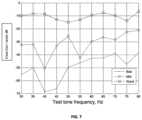
- FIG. 7is a graph illustrating different seal measurements in accordance with the present invention.
- the estimated un-normalized cross-correlation between the ECM signal and the test signali.e. sine wave
- the estimated un-normalized cross-correlation between the ECM signal and the test signali.e. sine wave
- the estimated un-normalized cross-correlation between the ECM signal and the test signali.e. sine wave
- Three different curvesare provided corresponding to a good fit (i.e. a tight optimal seal providing approximately 20-30 dB of acoustic attenuation), mid or partial seal (i.e. an ear-seal that could be characterized as “half in” providing approximately 10-15 dB of acoustic attenuation), and a poor seal (i.e. an ear-seal providing less than 10 dB of acoustic attenuation).
- the threshold used to determine whether the ear seal can be characterized as “good”is approximately ⁇ 20 dB, (i.e. 0.85 of FIG. 10 which corresponds to the value for XCorr_threshold 414 in FIG. 4 ).
- the test signal for testing a seal of a sealing sectionis less than 200 hertz.
- the frequency of the emitted test signalis chosen to satisfy the requirements of being able to reveal small degradations in ear seal quality. It is also beneficial if the selected test signal frequency can be acoustically masked by reproduced audio to minimize detection of the test by an earpiece user. Both of these criteria are met using a test signal frequency below 200 Hz. The sensitivity is highest from the measured data at frequencies below 50 Hz. Conversely, as the test signal frequency increases the cross-correlation difference between a “good” and “bad” acoustic seal decreases.
- the cross-correlation for a “good” ear sealis ⁇ 8 dB, and for a bad ear seal it is ⁇ 68 dB (i.e. a 60 dB difference).
- the cross-correlation for a “good” ear sealis ⁇ 8 dB and for a bad ear seal it is ⁇ 38 dB (i.e. a 30 dB difference).
- the cross-correlation difference between a “good” and “bad” acoustic sealis further reduced thereby reducing the sensitivity of the test.
- FIG. 8is a flowchart to adjust the degree of acoustic sealing of an Inflation Management System (IMS) in accordance with an exemplary embodiment.
- the IMSis adjusted depending on the degree of acoustic sealing provided by an earpiece.
- the methodbegins at step 802 .
- the acoustic sealingis measured as disclosed in FIG. 7 and the result provided in a step 804 to determine the cross-correlation (XCorr) between a test signal and corresponding ECM signal.
- XCorrcross-correlation
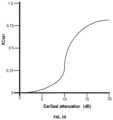
- An exemplary graph showing the relationship between XCorr and acoustic sealingis given in FIG. 10 .
- the degree of acoustic sealingis determined from known XCorr using a look-up (or “hash”) table or using a formula (e.g. of a polynomial form) that maps the acoustic sealing to the known XCorr value.
- the ambient sound levelis measured in a step 806 .
- the ambient sound levelcorresponds to the noise level in proximity to the user. In general, a higher degree of attenuation is desired when the ambient sound levels are high. Conversely, at low ambient sound levels the attenuation level of the IMS may be less of an issue and comfort more of a factor.
- the IMSis adjusted in a step 808 to meet the attenuation needs. In general, inflating the IMS increases attenuation while deflating the IMS decreases attenuation. The method terminates at step 810 .
- FIG. 9a more detailed flowchart to adjust the degree of acoustic sealing of an Inflation Management System (IMS) is shown.
- IMSInflation Management System
- the attenuationincreases when the pressure in the IMS is raised thereby allowing a degree of control to make adjustments. For example, an adjustment is made to increase attenuation when the background noise level rises or a seal check produces a failed result. Adjustments are made until the seal check passes.
- the pressure level adjustments of the IMSwill fall within a comfort range of a user (e.g., between 0.1 bar and 0.3 bar gauge pressure). Typically, the pressure level is set at a minimum level to achieve a predetermined attenuation level.
- the methodbegins at step 902 .
- the degree of acoustic sealingis determined from cross-correlation between the ECM signal and the generated test signal.
- the XCorr valueis provided in a step 904 .
- the attenuation provided by the IMSis calculated (equation) or looked up (table) from data such as that shown in FIG. 10 .
- the desired attenuation valueis dependant on the ambient sound level of the user.
- the desired attenuation valueis dependant on the ear-canal sound level of the user.
- the desired attenuation valueis dependant on the level of audio content (e.g. speech or music audio) reproduced with the earphone device.
- the desired attenuation valueis determined by one or more of the embodiments in a step 907 .
- the difference between the degree of acoustic sealing determined in step 906 and the desired attenuation value determined in step 907is calculated in step 908 .
- the difference value in step 908is used to determine the change in pressure of the IMS necessary to minimize the difference value in a step 910 .
- the difference value of the attenuationis converted into a corresponding pressure value change (e.g. in milli-Bars) using a similar look-up table or equation method as described previously.
- the pressure change in the IMSis then affected with step 912 to meet the desired attenuation level.
- a pressure of a variable volume inflatable systemcan have a gauge pressure of about 0.15 bar. If the desired attenuation is a decrease of 20 dB across the earpiece in the ear canal then the gauge pressure can be increased to about 0.25 bar, where an increased pressure is associated with an increase in attenuation.
- An experimental table for each earpiececan be generated in a standard devised experimental setup (e.g. impedance tunnel) and referred to when changes are needed. The method ends at step 914 .
- test signal fundamentalis illustrated.
- the test signalis masked or used in a manner undetectable by the user or made pleasant such that the user is unaware that the test signal is being played. This allows unobtrusive (periodic or non-periodic) testing to determine if a device is sealed correctly ensuring optimum system performance and more importantly user safety.
- an audio content 1102is provided.
- a step 1104stores audio content 1102 in a data buffer.
- audio content 1102is music played from a media player and received via a wired or wireless connection to at least one earpiece in the user's ear.
- An alternate examplewould be that audio content 1102 is a speech audio signal from a portable telephone device or the like.
- a step 1106determines if the buffer of audio content 1102 comprises a strong tonal signal component. Mixing the test signal having a similar fundamental frequency as audio content 1102 will mask the test signal when played to the user. Thus, the test signal is musically in harmony with the reproduced music and results in very little perceptual degradation in sound quality.
- a step 1108determines whether to update or generate the first fundamental tone for the test signal.
- the test signalis not updated or generated if buffered audio content 402 does not contain a strong tonal signal component.
- a return to step 1104fills the buffer with the next audio content 402 for analysis.
- a step 1110analyzes the buffer of data of audio content 1102 when it has been determined that it contains a strong tonal signal component.
- Step 1110determines the fundamental frequency of the tonal signal.
- the fundamental toneoften referred to as the fundamental and abbreviate f 0 is the lowest frequency in a harmonic series.
- the fundamental frequency (also called a natural frequency) of a periodic signalis the inverse of the pitch period length.
- the pitch periodis the smallest repeating unit of a signal.
- the fundamental frequency of the tonal signalcan be calculated using an autocorrelation analysis.
- a mathematical operation 1114is performed where the frequency component of the test signal is limited to a frequency range below a lower minimum and upper maximum frequency range.
- Fund_ratiois calculated, which is defined as a ratio of the determined fundamental frequency (F_fund) of the tonal signal from step 1110 to an upper threshold value F_fund threshold 1112 , which in one exemplary embodiment, is a fixed constant equal to approximately 100 Hz.
- F_fund threshold 1112is chosen to be a low frequency value which is above the lowest (or ⁇ 3 dB) frequency that a transducer can reproduce, but below a predetermined frequency.
- a comparison step 1116if the estimated F-fund is higher than the F_fund threshold 1112 (ratio >1), then F_fund is reduced by an integer multiple to be below F_fund threshold 1112 corresponding to the mathematical operation of step 1118 . Otherwise, the test signal fundamental is equal to F_fund as shown in step 1120 . Although not shown, the calculated test signal fundamental is compared and determined to be greater than a predetermined threshold.
- processor 116is configured to receive or generate audio content.
- the audio contentcan from external devices such as a portable phone or a media player.
- Memory 104can be used as a buffer for the audio content.
- Processor 116is configured to receive the buffer of audio content from memory 104 .
- the steps and calculations of the block diagram of FIG. 4are then performed by processor 116 .
- the resultbeing one of the identification of a strong tonal signal component in the buffer of audio content and the test signal fundamental or loading the buffer with new audio content and starting the process again.
- a flowchart of an exemplary embodiment to determine tonal presence in audio contentis shown.
- the exemplary embodimentrelates to step 1106 of FIG. 11 that analyzes audio content stored in a buffer.
- the methodbegins at step 1202 .
- a step 1204gets the audio content stored in an audio signal buffer hereinafter called the audio signal.
- a filter step 1206filters the audio signal to a frequency range of interest that relates to a sealing test frequency. For example, a band pass filter in the range of 20 Hz to 500 Hz could be used to filter the audio signal where the test signal is in the lower audio frequency range.
- An auto-correlation step 1208analyzes the audio signal where a strong tonal signal component is represented by peaks in the analysis results.
- a step 1210generates Absolute(Acorr) which is a number representing the absolute magnitude of the peaks from the analysis. For example, Absolute(Acorr) can be the square of the results from the auto-correlation.
- a crest_factor_Acorr 1218is generated from the results by calculating an RMS value 1214 (or time-averaged peak value) and peak value 1216 (or time averaged peak value).
- the crest_factor_Acorr 1218is the ratio of the peak value to the RMS value of an absolute auto-correlation sequence of the audio signal.
- a comparison step 1222is then performed.
- a strong tonal presenceis identified when crest_factor_Acorr 1218 is greater than a threshold Crest_factor_Acorr_threshold 1220 . Identification of the strong tonal presence indicates the audio signal would facilitate masking of the test signal to determine sealing of the device (step 1226 ).
- the audio signalis not used in conjunction with the test signal if crest_factor_Acorr 1218 is less than Crest_factor_Acorr_threshold 1220 (step 1224 ). The process would begin again loading a next sequence of the audio signal into the buffer for review.
- audio contentis stored in a buffer, for example memory 104 .
- the audio content in the bufferis provided to processor 116 .
- processor 116runs the analysis as described in the block diagram of FIG. 12 thereby determining if a strong tonal presence is found in the audio content in the buffer.
- New audio contentis loaded into the buffer (memory 104 ) if a strong tonal presence is not found beginning the procedure again.
- a flowchart of a method to determine when to emit the test signalbegins at step 1302 .
- the test signalis emitted when the test can be performed unobtrusively to the user and also provide an accurate test.
- an audio signalis retrieved from a buffer.
- the audio signalis received from an ECM or an ASM.
- the audio signalis measured to determine when the sound level is low in the ear canal, the ambient environment, or both.
- the test signalis emitted when the sound level is low.
- a filter step 1306band pass filters the audio signal.
- filter step 1306filters the audio signal from 50 Hz to 150 Hz which corresponds to a frequency range of the test signal.
- the RMS of the audio signalis calculated.
- the audio signalis analyzed to detect when the energy within an audio frequency range is below a threshold RMS_threshold 1310 .
- the RMS of the audio signalis the signal level in the volume being measured.
- a comparison step 1312compares the measured RMS level of the filtered audio signal against RMS_threshold 1310 .
- a test signalis emitted when the measured RMS value is less than RMS_threshold 1310 . No test signal is emitted when the RMS of the audio signal is greater than RMS_threshold 1310 .
- the methodends at step 1316 .
- an earpiece seal integritycorresponds to a full or partial acoustic barrier between a first volume (ear canal) and a second volume (ambient environment).
- the degree of acoustic seal integrityis expressed as either a PASS or FAIL status, where FAIL indicates that the acoustic seal is compromised relative to a normal operating acoustic seal.
- FAILindicates that the acoustic seal is compromised relative to a normal operating acoustic seal.
- an earpiece that has performed the seal test and determined that the sealing unit is not sealed correctly in the ear canal of the usercan provide a signal or message indicating the problem. The user can then remove, reinsert, and retest the earpiece to ensure that the seal is within normal operating specifications.
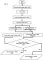
- the methodbegins at step 1402 .
- An acoustic test signalis provided in a first volume.
- a transducermeasures the acoustic test signal and stores it in a signal buffer.
- a second transducer in a second volume isolated from the first volume by an acoustic barriermeasures a second acoustic signal in the second volume.
- a portion of the acoustic test signalpasses the acoustic barrier into the second volume.
- the amount of the acoustic test signal passing the acoustic barrieris a measure of the seal provided by the acoustic barrier.
- a filter step 1408the measured acoustic test signal in the first volume is filtered in a frequency range corresponding to the acoustic test signal to remove signals that are not part of the test.
- the measured signal from the first volumeis heretofore called the first volume signal.
- the measured signal in the second volumeis filtered in a frequency range corresponding to the acoustic test signal to remove signals not related to the test (outside the frequency range) in the second volume.
- the measured signal from the second volumeis heretofore called the second volume signal.
- a correlation, cross-correlation, or coherence analysisis performed on the first volume signal and the second volume signal.
- the correlation, cross-correlation, or coherence analysisis a measure of the similarity of the signals in the first and second volumes.
- the non-difference analysismeasures the acoustic test signal leaking past the acoustic barrier by identifying the portion of the second volume signal that is similar to the acoustic test signal in the first volume.
- a correlation step 1412is performed comprising a cross-correlation of the first volume signal and the second volume signal.
- the peak of the cross-correlationis identified.
- the peak of the cross-correlationis Absolute(XCorr).
- the Lag-time of Peak 1420 and the Magnitude of Peak 1422is calculated.
- the Lag-time of Peak 1420is a measure of the time delay between receiving the signals in the first and second volumes.
- the first volume signalshould be received before the second volume signal.
- the Magnitude of Peak 1422corresponds to the similarity between the signals in the first and second volumes.
- a larger number for Magnitude of Peakrelates to more leakage of the acoustic test signal getting past the acoustic barrier.
- a comparison step 1426the measured Lag-time of Peak is compared against Target Lag Limits 1424 .
- the measured lag-timeshould fall within the predetermined range (Target Lag Limits 1424 ) for the seal test to be valid. If the Lag-time of Peak is within the appropriate range then a logic 1 is provided to AND function 1432 , otherwise a logic 0 is provided.
- a second comparison step 1428the Magnitude of Peak is compared against a Peak_threshold 1430 .
- a FAIL output 1434corresponds to a logic 1 at the output of AND function 1432 .
- the FAILoccurs when the Lag-time of Peak is within the predetermined range and the Magnitude of Peak is greater than the Peak_threshold indicating that the acoustic barrier is sealed improperly. All other conditions indicate a PASS output 1434 and the acoustic barrier is sealed correctly.
- an earpieceis tested to determine if sealing unit 108 is sealed correctly to the ear canal of the user.
- Sealing unit 108creates a first volume in ear canal 124 and a second volume outside the ear canal 124 in the ambient environment.
- a masking approachis used to perform seal testing unobtrusively to the user.
- the useris listening to music or speech (audio content) provided to ear canal 124 from ECR 114 .
- the music or speechis buffered in memory 104 or memory in processor 116 .
- Processor 116analyzes the audio content in the buffer to identify a strong tonal content.
- a test signalcan be created once audio content with strong tonal content is found.
- the test signalwill have at least one fundamental pitch corresponding to the strong tonal content and optionally further harmonics.
- Processor 116also analyzes the measured signals from ECM 106 and ASM 120 to determine when to emit the test signal.
- Processor 116monitors and compares the sound level in the ambient environment and ear canal 124 .
- Processor 116will provide the generated test signal to ECR 114 during an optimum time for test accuracy such as when the ambient sound level is low, the ear canal sound level is low, or both. Also, processor 116 will not output the test signal if there is audio content similar to the test signal in the ear canal or ambient environment.
- Processor 116monitors the test conditions and then provides the test signal to ECR 114 when an accurate sealing test can be performed.
- ECR 114outputs an acoustic test signal which may or may not have other audio content.
- ECM 106 and ASM 120respectively measure acoustic signals in ear canal 124 and the ambient environment.
- Processor 116is operatively coupled to ECM 106 and ASM 120 . The measured signals are buffered in memory 104 .
- a cross-correlationis used to measure the similarity between the signals in ear canal 124 and the ambient environment.
- Processor 116performs the cross-correlation calculations using the measured acoustic signals from ECM 106 and ASM 120 .
- the cross-correlationis used to identify and compare the acoustic test signal present in the two volumes separated by the acoustic barrier.
- ASM(n)is the n th sample of the ASM signal
- ECM(n ⁇ 1)is the (n ⁇ 1) th sample of the ECM signal.
- a peak of the absolute cross-correlationis estimated using a peak-picking function and also the lag time at which this peak occurs (i.e. the index I at which this occurs).
- the Lag-time of Peak and the Magnitude of Peakare known and respectively compared against a Target Lag Limit range and a Peak Threshold.
- the user of the earpieceis notified or warned that sealing unit 108 is improperly sealed by processor 116 if the measured Lag-time of Peak is within the Target Lag Limit range and the Magnitude of Peak is greater than the Peak Threshold.
- Coherenceis also a measure of similarity between two signals.
- Coherenceis another non-difference comparison approach that can be used for detecting acoustic seal integrity. Coherence is defined as:
- ⁇ x ⁇ y 2⁇ " ⁇ [LeftBracketingBar]" G x ⁇ y ( f ) ⁇ " ⁇ [RightBracketingBar]” 2 G xx ( f ) ⁇ G y ⁇ y ( f ) ( 6 )
- Gxyis the cross-spectrum of two signals (e.g. the ASM and ECM signals), and can be calculated by first computing the cross-correlation in equation (5), applying a window function, for example a Hanning window, and transforming to the frequency domain, for example via an FFT.
- Gxx or Gyyis the auto-power spectrum of either the ASM or ECM signals, and can be calculated by first computing the auto-correlation (using equation 5, but where the two input signals are both from either the ASM or ECM and transforming to the frequency domain.
- the coherence functiongives a frequency-dependent vector between 0 and 1, where a high coherence at a particular frequency indicates a high degree of coherence at this frequency, and can therefore be used to analyze test signal frequencies in the ASM and ECM signals whereby a high coherence indicates the presence of the test signal in the ambient environment (indicating leakage past the acoustic barrier).
- FIGS. 15 A and 15 Billustrate a method of varying the seal of an inflation system in accordance with at least one exemplary embodiment.
- a seal varying devicee.g., 1500
- the signalcan be instructions to send a current over a period of time to an actuator, which can decrease the overall volume of the system (hence increasing the pressure and effectively the sealing).
- an actuatorsuch as the P-653 PILine® can be used.
- FIGS. 15 A and 15 Bshows a slider actuator 1500 , with a moving slide 1510 , having attached a pumping arm 1560 , with a hole 1550 covering bump 1520 .
- the actuatorcan move 1570 such that the bump 1520 covers the hole 1550 in a bellows 1530 pump.
- the actuationcompresses the miniature bellows 1530 pushing 1590 gas through the one-way valve 1540 , upon the back stroke the bump 1520 uncovers the hole 1550 and air rushes back into the bellows 1530 for the next pump.
- the stroke lengthis 2 mm and the pump arm 1560 contact area is about 9 mm 2 then each stroke moves 18 mm 3 of volume.
- an inflation system 1570needs to be inflated more (e.g., more gas to increase sealing) then each stroke can provide an additional volume of gas of 18 mm 3 into the system increasing the inflation system 1580 .
- the inflation systemis initially empty (e.g., needs 1000 mm 3 of gas volume to inflate) then about 56 strokes would be needed for inflation, which is about 110 mm one direction stroke length or about 2 seconds at P-653 PILine speeds.
- the number of oscillations and stroke lengthcan be determined according to the signal 1505 sent, which can be specifically tailored depending upon the electronics controlling the actuators. Note that PI-653 is an example only. Other actuation systems can be used and controlled by signal 1505 .
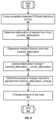
- FIG. 16illustrates a block diagram of controlled sealing in response to a seal fail signal and/or a request for increased seal attenuation.
- a command signal 1600is received (e.g., a seal fail signal in which a default attenuation value is attached for example 15 dB, or a signal requesting an additional amount of attenuation) by a processor.
- the command signalspecifies an additional amount of attenuation or that the seal has failed.
- An attenuation needed Nis identified 1610 .
- an experimental tableis queried to find the pressure needed P which is then subtracted from the current pressure to obtain an increase in pressure DP needed.
- the increase in pressureis converted into a volume of gas increase needed (e.g., again referring to experimental tables based upon the inflation system volume).
- the volume of gas increase neededcan then be directly linked with the number of cycles of an actuator pump M, 1620 .
- the number of requested cycles Mcan then be sent 1630 to the actuator control circuit to pump the designated number of cycles.
- the systemcan then retest the attenuation 1640 and if refinements are needed the process can start again.
Landscapes
- Physics & Mathematics (AREA)
- Engineering & Computer Science (AREA)
- Acoustics & Sound (AREA)
- Signal Processing (AREA)
- Health & Medical Sciences (AREA)
- General Health & Medical Sciences (AREA)
- Otolaryngology (AREA)
- Neurosurgery (AREA)
- Headphones And Earphones (AREA)
- Soundproofing, Sound Blocking, And Sound Damping (AREA)
Abstract
Description
Where Γ is a small constant, e.g.10E-3.
8. In
9. In
10. In step520, the new temporary estimate of the correlation newRho_temp is calculated as: newRho_temp=(delta-beta*rho_old))
11. In
12. In
13. In
XCorr(n,l)=Σn=0NASM(n)ECM(n−l), (5)
Claims (20)
Priority Applications (3)
| Application Number | Priority Date | Filing Date | Title |
|---|---|---|---|
| US17/182,570US11665493B2 (en) | 2008-09-19 | 2021-02-23 | Acoustic sealing analysis system |
| US18/092,645US11889275B2 (en) | 2008-09-19 | 2023-01-03 | Acoustic sealing analysis system |
| US18/515,254US20240137719A1 (en) | 2008-09-19 | 2023-11-20 | Acoustic sealing analysis system |
Applications Claiming Priority (8)
| Application Number | Priority Date | Filing Date | Title |
|---|---|---|---|
| US9825008P | 2008-09-19 | 2008-09-19 | |
| US12/555,864US8600067B2 (en) | 2008-09-19 | 2009-09-09 | Acoustic sealing analysis system |
| US14/054,015US9113267B2 (en) | 2008-09-19 | 2013-10-15 | Acoustic sealing analysis system |
| US14/827,332US9781530B2 (en) | 2008-09-19 | 2015-08-17 | Acoustic sealing analysis system |
| US15/700,511US10299053B2 (en) | 2008-09-19 | 2017-09-11 | Acoustic sealing analysis system |
| US16/414,136US10701499B2 (en) | 2008-09-19 | 2019-05-16 | Acoustic sealing analysis system |
| US16/838,277US10979836B2 (en) | 2008-09-19 | 2020-04-02 | Acoustic sealing analysis system |
| US17/182,570US11665493B2 (en) | 2008-09-19 | 2021-02-23 | Acoustic sealing analysis system |
Related Parent Applications (1)
| Application Number | Title | Priority Date | Filing Date |
|---|---|---|---|
| US16/838,277ContinuationUS10979836B2 (en) | 2008-09-19 | 2020-04-02 | Acoustic sealing analysis system |
Related Child Applications (1)
| Application Number | Title | Priority Date | Filing Date |
|---|---|---|---|
| US18/092,645ContinuationUS11889275B2 (en) | 2008-09-19 | 2023-01-03 | Acoustic sealing analysis system |
Publications (2)
| Publication Number | Publication Date |
|---|---|
| US20210176576A1 US20210176576A1 (en) | 2021-06-10 |
| US11665493B2true US11665493B2 (en) | 2023-05-30 |
Family
ID=42037700
Family Applications (9)
| Application Number | Title | Priority Date | Filing Date |
|---|---|---|---|
| US12/555,864Active2032-08-14US8600067B2 (en) | 2008-09-19 | 2009-09-09 | Acoustic sealing analysis system |
| US14/054,015Active2030-04-02US9113267B2 (en) | 2008-09-19 | 2013-10-15 | Acoustic sealing analysis system |
| US14/827,332Active2030-01-14US9781530B2 (en) | 2008-09-19 | 2015-08-17 | Acoustic sealing analysis system |
| US15/700,511ActiveUS10299053B2 (en) | 2008-09-19 | 2017-09-11 | Acoustic sealing analysis system |
| US16/414,136ActiveUS10701499B2 (en) | 2008-09-19 | 2019-05-16 | Acoustic sealing analysis system |
| US16/838,277ActiveUS10979836B2 (en) | 2008-09-19 | 2020-04-02 | Acoustic sealing analysis system |
| US17/182,570Active2030-04-20US11665493B2 (en) | 2008-09-19 | 2021-02-23 | Acoustic sealing analysis system |
| US18/092,645ActiveUS11889275B2 (en) | 2008-09-19 | 2023-01-03 | Acoustic sealing analysis system |
| US18/515,254PendingUS20240137719A1 (en) | 2008-09-19 | 2023-11-20 | Acoustic sealing analysis system |
Family Applications Before (6)
| Application Number | Title | Priority Date | Filing Date |
|---|---|---|---|
| US12/555,864Active2032-08-14US8600067B2 (en) | 2008-09-19 | 2009-09-09 | Acoustic sealing analysis system |
| US14/054,015Active2030-04-02US9113267B2 (en) | 2008-09-19 | 2013-10-15 | Acoustic sealing analysis system |
| US14/827,332Active2030-01-14US9781530B2 (en) | 2008-09-19 | 2015-08-17 | Acoustic sealing analysis system |
| US15/700,511ActiveUS10299053B2 (en) | 2008-09-19 | 2017-09-11 | Acoustic sealing analysis system |
| US16/414,136ActiveUS10701499B2 (en) | 2008-09-19 | 2019-05-16 | Acoustic sealing analysis system |
| US16/838,277ActiveUS10979836B2 (en) | 2008-09-19 | 2020-04-02 | Acoustic sealing analysis system |
Family Applications After (2)
| Application Number | Title | Priority Date | Filing Date |
|---|---|---|---|
| US18/092,645ActiveUS11889275B2 (en) | 2008-09-19 | 2023-01-03 | Acoustic sealing analysis system |
| US18/515,254PendingUS20240137719A1 (en) | 2008-09-19 | 2023-11-20 | Acoustic sealing analysis system |
Country Status (1)
| Country | Link |
|---|---|
| US (9) | US8600067B2 (en) |
Cited By (5)
| Publication number | Priority date | Publication date | Assignee | Title |
|---|---|---|---|---|
| US20220408175A1 (en)* | 2021-06-18 | 2022-12-22 | Anna Barnacka | Vibroacoustic Earbud |
| US12349097B2 (en) | 2010-12-30 | 2025-07-01 | St Famtech, Llc | Information processing using a population of data acquisition devices |
| US12363223B2 (en) | 2013-09-22 | 2025-07-15 | ST R&DTech LLC | Real-time voice paging voice augmented caller ID/ring tone alias |
| US12374332B2 (en) | 2008-09-22 | 2025-07-29 | ST Fam Tech, LLC | Personalized sound management and method |
| US12389154B2 (en) | 2012-12-17 | 2025-08-12 | St Famtech, Llc | Shared earpiece communication |
Families Citing this family (101)
| Publication number | Priority date | Publication date | Assignee | Title |
|---|---|---|---|---|
| US11217237B2 (en) | 2008-04-14 | 2022-01-04 | Staton Techiya, Llc | Method and device for voice operated control |
| US11291456B2 (en) | 2007-07-12 | 2022-04-05 | Staton Techiya, Llc | Expandable sealing devices and methods |
| US8992710B2 (en) | 2008-10-10 | 2015-03-31 | Personics Holdings, LLC. | Inverted balloon system and inflation management system |
| US8554350B2 (en) | 2008-10-15 | 2013-10-08 | Personics Holdings Inc. | Device and method to reduce ear wax clogging of acoustic ports, hearing aid sealing system, and feedback reduction system |
| US8705783B1 (en)* | 2009-10-23 | 2014-04-22 | Advanced Bionics | Methods and systems for acoustically controlling a cochlear implant system |
| US8401200B2 (en)* | 2009-11-19 | 2013-03-19 | Apple Inc. | Electronic device and headset with speaker seal evaluation capabilities |
| JP5598536B2 (en)* | 2010-03-31 | 2014-10-01 | 富士通株式会社 | Bandwidth expansion device and bandwidth expansion method |
| US8550206B2 (en) | 2011-05-31 | 2013-10-08 | Virginia Tech Intellectual Properties, Inc. | Method and structure for achieving spectrum-tunable and uniform attenuation |
| EP2586216A1 (en) | 2010-06-26 | 2013-05-01 | Personics Holdings, Inc. | Method and devices for occluding an ear canal having a predetermined filter characteristic |
| JP5965920B2 (en)* | 2011-01-05 | 2016-08-10 | コーニンクレッカ フィリップス エヌ ヴェKoninklijke Philips N.V. | Estimation of the sealing performance of the ear canal blockade |
| JP2012169828A (en)* | 2011-02-14 | 2012-09-06 | Sony Corp | Sound signal output apparatus, speaker apparatus, sound signal output method |
| CA2831678A1 (en) | 2011-03-28 | 2012-10-04 | Ambientz | Methods and systems for searching utilizing acoustical context |
| RU2588596C2 (en)* | 2011-03-30 | 2016-07-10 | Конинклейке Филипс Н.В. | Determination of distance and/or quality of acoustics between mobile device and base unit |
| US10362381B2 (en) | 2011-06-01 | 2019-07-23 | Staton Techiya, Llc | Methods and devices for radio frequency (RF) mitigation proximate the ear |
| CN102384821B (en)* | 2011-08-10 | 2015-07-29 | 歌尔声学股份有限公司 | Loudspeaker module air tightness testing method, test fixture and test macro |
| US9451368B2 (en)* | 2012-04-11 | 2016-09-20 | Envoy Medical Corporation | Feedback scan for hearing aid |
| US9002023B2 (en)* | 2012-04-17 | 2015-04-07 | Bose Corporation | In-ear audio device customization |
| WO2014039026A1 (en) | 2012-09-04 | 2014-03-13 | Personics Holdings, Inc. | Occlusion device capable of occluding an ear canal |
| WO2014043357A1 (en) | 2012-09-14 | 2014-03-20 | Robert Bosch Gmbh | Testing for defective manufacturing of microphones and ultralow pressure sensors |
| DE112013004483T5 (en) | 2012-09-14 | 2015-06-03 | Robert Bosch Gmbh | Verification of a device using an obstructing an acoustic opening |
| EP2980547B1 (en) | 2012-10-24 | 2021-04-07 | Kyocera Corporation | Vibration measurement device, measurement system, and measurement method |
| US10043535B2 (en) | 2013-01-15 | 2018-08-07 | Staton Techiya, Llc | Method and device for spectral expansion for an audio signal |
| US9270244B2 (en)* | 2013-03-13 | 2016-02-23 | Personics Holdings, Llc | System and method to detect close voice sources and automatically enhance situation awareness |
| US10045133B2 (en) | 2013-03-15 | 2018-08-07 | Natan Bauman | Variable sound attenuator with hearing aid |
| US9521480B2 (en) | 2013-07-31 | 2016-12-13 | Natan Bauman | Variable noise attenuator with adjustable attenuation |
| US9333116B2 (en) | 2013-03-15 | 2016-05-10 | Natan Bauman | Variable sound attenuator |
| US9654884B2 (en)* | 2013-05-21 | 2017-05-16 | Sonova Ag | Method of fitting a hearing instrument, and impression tool |
| US9107011B2 (en)* | 2013-07-03 | 2015-08-11 | Sonetics Holdings, Inc. | Headset with fit detection system |
| JP2015023499A (en)* | 2013-07-22 | 2015-02-02 | 船井電機株式会社 | Sound processing system and sound processing apparatus |
| DE102013217235A1 (en)* | 2013-08-29 | 2015-03-05 | Sennheiser Electronic Gmbh & Co. Kg | Handset and headset |
| NL2011551C2 (en) | 2013-10-03 | 2015-04-07 | Dynamic Ear Company B V | Method and system for testing a mould shape quality of a user-customized ear mould. |
| US10045135B2 (en) | 2013-10-24 | 2018-08-07 | Staton Techiya, Llc | Method and device for recognition and arbitration of an input connection |
| US9959886B2 (en)* | 2013-12-06 | 2018-05-01 | Malaspina Labs (Barbados), Inc. | Spectral comb voice activity detection |
| US9564128B2 (en)* | 2013-12-09 | 2017-02-07 | Qualcomm Incorporated | Controlling a speech recognition process of a computing device |
| US10043534B2 (en) | 2013-12-23 | 2018-08-07 | Staton Techiya, Llc | Method and device for spectral expansion for an audio signal |
| CN103702259B (en) | 2013-12-31 | 2017-12-12 | 北京智谷睿拓技术服务有限公司 | Interactive device and exchange method |
| CN103747409B (en)* | 2013-12-31 | 2017-02-08 | 北京智谷睿拓技术服务有限公司 | Loud-speaking device and method as well as interaction equipment |
| US10163453B2 (en) | 2014-10-24 | 2018-12-25 | Staton Techiya, Llc | Robust voice activity detector system for use with an earphone |
| US9924288B2 (en)* | 2014-10-29 | 2018-03-20 | Invensense, Inc. | Blockage detection for a microelectromechanical systems sensor |
| US10413240B2 (en) | 2014-12-10 | 2019-09-17 | Staton Techiya, Llc | Membrane and balloon systems and designs for conduits |
| CN104661153B (en)* | 2014-12-31 | 2018-02-02 | 歌尔股份有限公司 | A kind of compensation method of earphone audio, device and earphone |
| US10709388B2 (en) | 2015-05-08 | 2020-07-14 | Staton Techiya, Llc | Biometric, physiological or environmental monitoring using a closed chamber |
| WO2016195559A1 (en)* | 2015-06-05 | 2016-12-08 | Telefonaktiebolaget Lm Ericsson (Publ) | Changing the acoustic performance of a sound emitting device |
| US11477560B2 (en) | 2015-09-11 | 2022-10-18 | Hear Llc | Earplugs, earphones, and eartips |
| US10937407B2 (en) | 2015-10-26 | 2021-03-02 | Staton Techiya, Llc | Biometric, physiological or environmental monitoring using a closed chamber |
| US20170195811A1 (en)* | 2015-12-30 | 2017-07-06 | Knowles Electronics Llc | Audio Monitoring and Adaptation Using Headset Microphones Inside User's Ear Canal |
| US10764226B2 (en) | 2016-01-15 | 2020-09-01 | Staton Techiya, Llc | Message delivery and presentation methods, systems and devices using receptivity |
| US10616693B2 (en) | 2016-01-22 | 2020-04-07 | Staton Techiya Llc | System and method for efficiency among devices |
| US9812149B2 (en)* | 2016-01-28 | 2017-11-07 | Knowles Electronics, Llc | Methods and systems for providing consistency in noise reduction during speech and non-speech periods |
| US11082779B2 (en) | 2016-03-11 | 2021-08-03 | Widex A/S | Method and hearing assistive device for handling streamed audio, and an audio signal for use with the method and the hearing assistive device |
| WO2017152992A1 (en) | 2016-03-11 | 2017-09-14 | Widex A/S | Method and hearing assisting device for handling streamed audio |
| US10104459B2 (en) | 2016-10-14 | 2018-10-16 | Htc Corporation | Audio system with conceal detection or calibration |
| WO2018077800A1 (en)* | 2016-10-27 | 2018-05-03 | Harman Becker Automotive Systems Gmbh | Acoustic signaling |
| CN106535024A (en)* | 2016-12-06 | 2017-03-22 | 深圳精拓创新科技有限公司 | Power amplifier circuit, control method and earphone system |
| US20210153461A1 (en) | 2017-01-26 | 2021-05-27 | Daniel Ferland | Noise attenuation earphone device for animals |
| US11115750B2 (en) | 2017-06-26 | 2021-09-07 | Ecole De Technologie Superieure | System, device and method for assessing a fit quality of an earpiece |
| DE102017215825B3 (en)* | 2017-09-07 | 2018-10-31 | Sivantos Pte. Ltd. | Method for detecting a defect in a hearing instrument |
| CN109756807A (en)* | 2017-11-08 | 2019-05-14 | 深圳市佳骏兴科技有限公司 | Communication device and mobile terminal with whisper conduction function |
| CN107920298B (en)* | 2018-01-03 | 2019-07-05 | 京东方科技集团股份有限公司 | A kind of earphone, earphone control method and device |
| US10951994B2 (en)* | 2018-04-04 | 2021-03-16 | Staton Techiya, Llc | Method to acquire preferred dynamic range function for speech enhancement |
| CN112334867A (en) | 2018-05-24 | 2021-02-05 | 纽约州立大学研究基金会 | Capacitive sensor |
| CN109151145B (en)* | 2018-09-07 | 2021-03-02 | 深圳市万普拉斯科技有限公司 | Method and device for detecting audio channel |
| US11418865B2 (en)* | 2018-12-07 | 2022-08-16 | Gn Hearing A/S | Configurable hearing devices |
| WO2020131963A1 (en) | 2018-12-21 | 2020-06-25 | Nura Holdings Pty Ltd | Modular ear-cup and ear-bud and power management of the modular ear-cup and ear-bud |
| EP3931737B1 (en) | 2019-03-01 | 2025-10-15 | Nura Holdings PTY Ltd | Headphones with timing capability and enhanced security |
| US20220174389A1 (en)* | 2019-03-26 | 2022-06-02 | Nitto Denko Corporation | Earplug, sound collector, and volume measurement system |
| JP2020163098A (en)* | 2019-03-26 | 2020-10-08 | 日東電工株式会社 | Earplugs, sound collectors, and volume measurement systems |
| CN111818437A (en)* | 2019-04-12 | 2020-10-23 | 美律电子(惠州)有限公司 | Headphone Acoustic Test Device |
| CN111988690B (en)* | 2019-05-23 | 2023-06-27 | 小鸟创新(北京)科技有限公司 | Earphone wearing state detection method and device and earphone |
| DE102020117780A1 (en)* | 2019-07-08 | 2021-01-14 | Apple Inc. | ACOUSTIC DETECTION OF THE FIT OF IN-EAR-HEADPHONES |
| US11706555B2 (en) | 2019-07-08 | 2023-07-18 | Apple Inc. | Setup management for ear tip selection fitting process |
| US11172298B2 (en) | 2019-07-08 | 2021-11-09 | Apple Inc. | Systems, methods, and user interfaces for headphone fit adjustment and audio output control |
| US11470413B2 (en)* | 2019-07-08 | 2022-10-11 | Apple Inc. | Acoustic detection of in-ear headphone fit |
| CN110636432A (en)* | 2019-09-29 | 2019-12-31 | 深圳市火乐科技发展有限公司 | Microphone testing method and related equipment |
| CN110806850B (en)* | 2019-11-01 | 2023-07-04 | 美特科技(苏州)有限公司 | Earphone, automatic volume adjustment control module and method thereof and storage medium |
| US11405717B2 (en)* | 2019-12-17 | 2022-08-02 | Casey Kong Ng | Pressure equalizing earphone |
| CN111683328A (en)* | 2020-04-22 | 2020-09-18 | 苏州市运泰利自动化设备有限公司 | Sounding device test system and method |
| US11115766B1 (en)* | 2020-05-28 | 2021-09-07 | Zebra Technologies Corporation | Automated audio assembly performance assessment |
| US11652510B2 (en) | 2020-06-01 | 2023-05-16 | Apple Inc. | Systems, methods, and graphical user interfaces for automatic audio routing |
| US11134354B1 (en)* | 2020-06-15 | 2021-09-28 | Cirrus Logic, Inc. | Wear detection |
| US11219386B2 (en) | 2020-06-15 | 2022-01-11 | Cirrus Logic, Inc. | Cough detection |
| US11206502B1 (en)* | 2020-06-17 | 2021-12-21 | Cirrus Logic, Inc. | System and method for evaluating an ear seal using normalization |
| US11516604B2 (en) | 2020-06-17 | 2022-11-29 | Cirrus Logic, Inc. | System and method for evaluating an ear seal using external stimulus |
| US11941319B2 (en) | 2020-07-20 | 2024-03-26 | Apple Inc. | Systems, methods, and graphical user interfaces for selecting audio output modes of wearable audio output devices |
| US12197809B2 (en) | 2020-07-20 | 2025-01-14 | Apple Inc. | Systems, methods, and graphical user interfaces for selecting audio output modes of wearable audio output devices |
| US11375314B2 (en) | 2020-07-20 | 2022-06-28 | Apple Inc. | Systems, methods, and graphical user interfaces for selecting audio output modes of wearable audio output devices |
| KR102736455B1 (en) | 2020-07-31 | 2024-12-02 | 삼성전자주식회사 | Electronic device and method for operating thereof |
| JP2023524868A (en) | 2020-08-29 | 2023-06-13 | シェンツェン・ショックス・カンパニー・リミテッド | METHOD AND SYSTEM FOR DETECTING STATE OF BONE CONDUCTION HEARING DEVICE |
| CN114143646B (en)* | 2020-09-03 | 2023-03-24 | Oppo广东移动通信有限公司 | Detection method, device, earphone and readable storage medium |
| US11842717B2 (en) | 2020-09-10 | 2023-12-12 | Maxim Integrated Products, Inc. | Robust open-ear ambient sound control with leakage detection |
| US11523243B2 (en) | 2020-09-25 | 2022-12-06 | Apple Inc. | Systems, methods, and graphical user interfaces for using spatialized audio during communication sessions |
| FR3121810A1 (en)* | 2021-04-09 | 2022-10-14 | Sagemcom Broadband Sas | Process for self-diagnosis of audio reproduction equipment |
| CN113382332B (en)* | 2021-05-14 | 2022-08-05 | 江西联创宏声电子股份有限公司 | Earphone set |
| EP4152767A4 (en)* | 2021-08-02 | 2023-09-06 | Samsung Electronics Co., Ltd. | PORTABLE ELECTRONIC DEVICE AND METHOD FOR OPERATING A PORTABLE ELECTRONIC DEVICE |
| US11850119B2 (en)* | 2021-09-03 | 2023-12-26 | Honeywell International Inc. | Hearing safety device |
| CN114245283B (en)* | 2021-12-10 | 2024-02-27 | 深圳市精泰达科技有限公司 | Method and system for testing microphone waterproof by sound |
| US12285317B2 (en) | 2022-07-14 | 2025-04-29 | Honeywell Safety Products Usa, Inc. | Apparatuses, computer-implemented methods, and computer program products for monitoring audio protector fit |
| CN115297421B (en)* | 2022-07-25 | 2025-01-28 | 深圳时空壶技术有限公司 | A headphone sound leakage testing method and device |
| US20240041403A1 (en)* | 2022-08-05 | 2024-02-08 | Interacoustics A/S | Hybrid ear-probe fit |
| EP4404584A1 (en)* | 2023-01-19 | 2024-07-24 | Nokia Technologies Oy | Apparatus, methods and computer programs for analyzing earphone sealing |
| WO2024168330A1 (en)* | 2023-02-11 | 2024-08-15 | Staton Techiya, Llc | Sealing determination method and device |
Citations (98)
| Publication number | Priority date | Publication date | Assignee | Title |
|---|---|---|---|---|
| US3876843A (en) | 1973-01-02 | 1975-04-08 | Textron Inc | Directional hearing aid with variable directivity |
| US4020297A (en) | 1976-01-15 | 1977-04-26 | Brodie S Dan | Adjustable headset |
| US4054749A (en) | 1975-12-02 | 1977-10-18 | Fuji Xerox Co., Ltd. | Method for verifying identity or difference by voice |
| US4088849A (en) | 1975-09-30 | 1978-05-09 | Victor Company Of Japan, Limited | Headphone unit incorporating microphones for binaural recording |
| US4947440A (en) | 1988-10-27 | 1990-08-07 | The Grass Valley Group, Inc. | Shaping of automatic audio crossfade |
| US5002151A (en)* | 1986-12-05 | 1991-03-26 | Minnesota Mining And Manufacturing Company | Ear piece having disposable, compressible polymeric foam sleeve |
| US5138722A (en) | 1991-07-02 | 1992-08-18 | David Clark Company Inc. | Headset ear seal |
| US5142587A (en) | 1989-06-16 | 1992-08-25 | Foster Electric Co., Ltd. | Intra-concha type electroacoustic transducer for use with audio devices etc. |
| US5208867A (en) | 1990-04-05 | 1993-05-04 | Intelex, Inc. | Voice transmission system and method for high ambient noise conditions |
| US5267321A (en) | 1991-11-19 | 1993-11-30 | Edwin Langberg | Active sound absorber |
| US5319163A (en) | 1990-06-07 | 1994-06-07 | Scott Robert T | Waterproof earmold-to-earphone adapter |
| US5524056A (en) | 1993-04-13 | 1996-06-04 | Etymotic Research, Inc. | Hearing aid having plural microphones and a microphone switching system |
| US5712453A (en) | 1994-04-28 | 1998-01-27 | Plantronics, Inc. | Concha headset stabilizer |
| US5764781A (en) | 1995-12-12 | 1998-06-09 | Ding; Chih-Shun | Speaker and amplifier system |
| US5903868A (en) | 1995-11-22 | 1999-05-11 | Yuen; Henry C. | Audio recorder with retroactive storage |
| US6021207A (en) | 1997-04-03 | 2000-02-01 | Resound Corporation | Wireless open ear canal earpiece |
| US6021325A (en) | 1997-03-10 | 2000-02-01 | Ericsson Inc. | Mobile telephone having continuous recording capability |
| US6163338A (en) | 1997-12-11 | 2000-12-19 | Johnson; Dan | Apparatus and method for recapture of realtime events |
| US6163508A (en) | 1999-05-13 | 2000-12-19 | Ericsson Inc. | Recording method having temporary buffering |
| US6226389B1 (en) | 1993-08-11 | 2001-05-01 | Jerome H. Lemelson | Motor vehicle warning and control system and method |
| US6298323B1 (en) | 1996-07-25 | 2001-10-02 | Siemens Aktiengesellschaft | Computer voice recognition method verifying speaker identity using speaker and non-speaker data |
| US6321070B1 (en) | 1998-05-14 | 2001-11-20 | Motorola, Inc. | Portable electronic device with a speaker assembly |
| US20010046304A1 (en)* | 2000-04-24 | 2001-11-29 | Rast Rodger H. | System and method for selective control of acoustic isolation in headsets |
| US6359993B2 (en) | 1999-01-15 | 2002-03-19 | Sonic Innovations | Conformal tip for a hearing aid with integrated vent and retrieval cord |
| US6400652B1 (en) | 1998-12-04 | 2002-06-04 | At&T Corp. | Recording system having pattern recognition |
| US6415034B1 (en) | 1996-08-13 | 2002-07-02 | Nokia Mobile Phones Ltd. | Earphone unit and a terminal device |
| US20020106091A1 (en) | 2001-02-02 | 2002-08-08 | Furst Claus Erdmann | Microphone unit with internal A/D converter |
| US20020118798A1 (en) | 2001-02-27 | 2002-08-29 | Christopher Langhart | System and method for recording telephone conversations |
| US6567524B1 (en)* | 2000-09-01 | 2003-05-20 | Nacre As | Noise protection verification device |
| US20030161097A1 (en) | 2002-02-28 | 2003-08-28 | Dana Le | Wearable computer system and modes of operating the system |
| US20030165246A1 (en) | 2002-02-28 | 2003-09-04 | Sintef | Voice detection and discrimination apparatus and method |
| US6661901B1 (en) | 2000-09-01 | 2003-12-09 | Nacre As | Ear terminal with microphone for natural voice rendition |
| USRE38351E1 (en) | 1992-05-08 | 2003-12-16 | Etymotic Research, Inc. | High fidelity insert earphones and methods of making same |
| US20040042103A1 (en) | 2002-05-31 | 2004-03-04 | Yaron Mayer | System and method for improved retroactive recording and/or replay |
| US6748238B1 (en) | 2000-09-25 | 2004-06-08 | Sharper Image Corporation | Hands-free digital recorder system for cellular telephones |
| US20040109668A1 (en) | 2002-12-05 | 2004-06-10 | Stuckman Bruce E. | DSL video service with memory manager |
| US6754359B1 (en) | 2000-09-01 | 2004-06-22 | Nacre As | Ear terminal with microphone for voice pickup |
| US20040125965A1 (en) | 2002-12-27 | 2004-07-01 | William Alberth | Method and apparatus for providing background audio during a communication session |
| US20040190737A1 (en) | 2003-03-25 | 2004-09-30 | Volker Kuhnel | Method for recording information in a hearing device as well as a hearing device |
| US20040196992A1 (en)* | 2003-04-01 | 2004-10-07 | Ryan Jim G. | System and method for detecting the insertion or removal of a hearing instrument from the ear canal |
| US6804643B1 (en) | 1999-10-29 | 2004-10-12 | Nokia Mobile Phones Ltd. | Speech recognition |
| US6804638B2 (en) | 1999-04-30 | 2004-10-12 | Recent Memory Incorporated | Device and method for selective recall and preservation of events prior to decision to record the events |
| US20040203351A1 (en) | 2002-05-15 | 2004-10-14 | Koninklijke Philips Electronics N.V. | Bluetooth control device for mobile communication apparatus |
| EP1519625A2 (en) | 2003-09-11 | 2005-03-30 | Starkey Laboratories, Inc. | External ear canal voice detection |
| US20050078838A1 (en) | 2003-10-08 | 2005-04-14 | Henry Simon | Hearing ajustment appliance for electronic audio equipment |
| US20050096899A1 (en)* | 2003-11-04 | 2005-05-05 | Stmicroelectronics Asia Pacific Pte., Ltd. | Apparatus, method, and computer program for comparing audio signals |
| US20050123146A1 (en) | 2003-12-05 | 2005-06-09 | Jeremie Voix | Method and apparatus for objective assessment of in-ear device acoustical performance |
| US20050288057A1 (en) | 2004-06-23 | 2005-12-29 | Inventec Appliances Corporation | Portable phone capable of being switched into hearing aid function |
| US20060067551A1 (en) | 2004-09-28 | 2006-03-30 | Cartwright Kristopher L | Conformable ear piece and method of using and making same |
| WO2006037156A1 (en) | 2004-10-01 | 2006-04-13 | Hear Works Pty Ltd | Acoustically transparent occlusion reduction system and method |
| US20060083395A1 (en) | 2004-10-15 | 2006-04-20 | Mimosa Acoustics, Inc. | System and method for automatically adjusting hearing aid based on acoustic reflectance |
| US20060092043A1 (en) | 2004-11-03 | 2006-05-04 | Lagassey Paul J | Advanced automobile accident detection, data recordation and reporting system |
| US7072482B2 (en) | 2002-09-06 | 2006-07-04 | Sonion Nederland B.V. | Microphone with improved sound inlet port |
| US20060195322A1 (en) | 2005-02-17 | 2006-08-31 | Broussard Scott J | System and method for detecting and storing important information |
| US7107109B1 (en) | 2000-02-16 | 2006-09-12 | Touchtunes Music Corporation | Process for adjusting the sound volume of a digital sound recording |
| US20060204014A1 (en) | 2000-03-02 | 2006-09-14 | Iseberg Steven J | Hearing test apparatus and method having automatic starting functionality |
| US20070019817A1 (en)* | 2005-07-22 | 2007-01-25 | Siemens Audiologische Technik Gmbh | Hearing device with automatic determination of its fit in the ear and corresponding method |
| US20070043563A1 (en) | 2005-08-22 | 2007-02-22 | International Business Machines Corporation | Methods and apparatus for buffering data for use in accordance with a speech recognition system |
| US20070086600A1 (en) | 2005-10-14 | 2007-04-19 | Boesen Peter V | Dual ear voice communication device |
| US7209569B2 (en) | 1999-05-10 | 2007-04-24 | Sp Technologies, Llc | Earpiece with an inertial sensor |
| US20070189544A1 (en) | 2005-01-15 | 2007-08-16 | Outland Research, Llc | Ambient sound responsive media player |
| US20070291953A1 (en) | 2006-06-14 | 2007-12-20 | Think-A-Move, Ltd. | Ear sensor assembly for speech processing |
| US20080037801A1 (en) | 2006-08-10 | 2008-02-14 | Cambridge Silicon Radio, Ltd. | Dual microphone noise reduction for headset application |
| US20080165988A1 (en) | 2007-01-05 | 2008-07-10 | Terlizzi Jeffrey J | Audio blending |
| US7430299B2 (en) | 2003-04-10 | 2008-09-30 | Sound Design Technologies, Ltd. | System and method for transmitting audio via a serial data port in a hearing instrument |
| US7433714B2 (en) | 2003-06-30 | 2008-10-07 | Microsoft Corporation | Alert mechanism interface |
| US7450730B2 (en) | 2004-12-23 | 2008-11-11 | Phonak Ag | Personal monitoring system for a user and method for monitoring a user |
| US20090010456A1 (en) | 2007-04-13 | 2009-01-08 | Personics Holdings Inc. | Method and device for voice operated control |
| US7477756B2 (en) | 2006-03-02 | 2009-01-13 | Knowles Electronics, Llc | Isolating deep canal fitting earphone |
| US20090024234A1 (en) | 2007-07-19 | 2009-01-22 | Archibald Fitzgerald J | Apparatus and method for coupling two independent audio streams |
| US20100061564A1 (en) | 2007-02-07 | 2010-03-11 | Richard Clemow | Ambient noise reduction system |
| US7756285B2 (en) | 2006-01-30 | 2010-07-13 | Songbird Hearing, Inc. | Hearing aid with tuned microphone cavity |
| US7778434B2 (en) | 2004-05-28 | 2010-08-17 | General Hearing Instrument, Inc. | Self forming in-the-ear hearing aid with conical stent |
| US7801318B2 (en) | 2005-06-21 | 2010-09-21 | Siemens Audiologisch Technik Gmbh | Hearing aid device with means for feedback compensation |
| US20100296668A1 (en) | 2009-04-23 | 2010-11-25 | Qualcomm Incorporated | Systems, methods, apparatus, and computer-readable media for automatic control of active noise cancellation |
| US7920557B2 (en) | 2007-02-15 | 2011-04-05 | Harris Corporation | Apparatus and method for soft media processing within a routing switcher |
| US20110096939A1 (en) | 2009-10-28 | 2011-04-28 | Sony Corporation | Reproducing device, headphone and reproducing method |
| US8014553B2 (en) | 2006-11-07 | 2011-09-06 | Nokia Corporation | Ear-mounted transducer and ear-device |
| US20110264447A1 (en) | 2010-04-22 | 2011-10-27 | Qualcomm Incorporated | Systems, methods, and apparatus for speech feature detection |
| US20110293103A1 (en) | 2010-06-01 | 2011-12-01 | Qualcomm Incorporated | Systems, methods, devices, apparatus, and computer program products for audio equalization |
| US8401200B2 (en) | 2009-11-19 | 2013-03-19 | Apple Inc. | Electronic device and headset with speaker seal evaluation capabilities |
| US20130177179A1 (en) | 2008-07-23 | 2013-07-11 | Asius Technologies Llc | Inflatable Ear Device |
| US8493204B2 (en) | 2011-11-14 | 2013-07-23 | Google Inc. | Displaying sound indications on a wearable computing system |
| US8550206B2 (en) | 2011-05-31 | 2013-10-08 | Virginia Tech Intellectual Properties, Inc. | Method and structure for achieving spectrum-tunable and uniform attenuation |
| US8750295B2 (en) | 2006-12-20 | 2014-06-10 | Gvbb Holdings S.A.R.L. | Embedded audio routing switcher |
| US8774435B2 (en) | 2008-07-23 | 2014-07-08 | Asius Technologies, Llc | Audio device, system and method |
| US8774433B2 (en) | 2006-11-18 | 2014-07-08 | Personics Holdings, Llc | Method and device for personalized hearing |
| US8971561B2 (en) | 2012-06-20 | 2015-03-03 | Apple Inc. | Earphone having a controlled acoustic leak port |
| US9037458B2 (en) | 2011-02-23 | 2015-05-19 | Qualcomm Incorporated | Systems, methods, apparatus, and computer-readable media for spatially selective audio augmentation |
| US9084060B2 (en) | 2012-07-18 | 2015-07-14 | Goertek, Inc. | Test device and test method for active noise reduction headphone |
| US9123343B2 (en) | 2006-04-27 | 2015-09-01 | Mobiter Dicta Oy | Method, and a device for converting speech by replacing inarticulate portions of the speech before the conversion |
| US9135797B2 (en) | 2006-12-28 | 2015-09-15 | International Business Machines Corporation | Audio detection using distributed mobile computing |
| US9293128B2 (en) | 2014-02-22 | 2016-03-22 | Apple Inc. | Active noise control with compensation for acoustic leak in personal listening devices |
| US9313572B2 (en) | 2012-09-28 | 2016-04-12 | Apple Inc. | System and method of detecting a user's voice activity using an accelerometer |
| US20160104452A1 (en) | 2013-05-24 | 2016-04-14 | Awe Company Limited | Systems and methods for a shared mixed reality experience |
| CN107071123A (en) | 2017-03-24 | 2017-08-18 | 上海与德科技有限公司 | Mobile terminal sound chamber method for testing tightness and test device |
| US20180176681A1 (en) | 2011-12-08 | 2018-06-21 | Sony Corporation | Earhole-wearable sound collection device, signal processing device, and sound collection method |
| US10860287B2 (en) | 2018-10-18 | 2020-12-08 | Yamaha Corporation | Sound output device and sound output method |
Family Cites Families (127)
| Publication number | Priority date | Publication date | Assignee | Title |
|---|---|---|---|---|
| US3014553A (en) | 1959-04-08 | 1961-12-26 | Allis Chalmers Mfg Co | Centrifugal steam separator |
| US3045840A (en) | 1961-06-30 | 1962-07-24 | Jr Harlan J Donelson | Material spreading mechanism |
| US5276740A (en) | 1990-01-19 | 1994-01-04 | Sony Corporation | Earphone device |
| US5327506A (en) | 1990-04-05 | 1994-07-05 | Stites Iii George M | Voice transmission system and method for high ambient noise conditions |
| US5251263A (en) | 1992-05-22 | 1993-10-05 | Andrea Electronics Corporation | Adaptive noise cancellation and speech enhancement system and apparatus therefor |
| WO1993026085A1 (en) | 1992-06-05 | 1993-12-23 | Noise Cancellation Technologies | Active/passive headset with speech filter |
| US5317273A (en) | 1992-10-22 | 1994-05-31 | Liberty Mutual | Hearing protection device evaluation apparatus |
| US5550923A (en) | 1994-09-02 | 1996-08-27 | Minnesota Mining And Manufacturing Company | Directional ear device with adaptive bandwidth and gain control |
| JPH0877468A (en) | 1994-09-08 | 1996-03-22 | Ono Denki Kk | Monitor device |
| US5577511A (en) | 1995-03-29 | 1996-11-26 | Etymotic Research, Inc. | Occlusion meter and associated method for measuring the occlusion of an occluding object in the ear canal of a subject |
| US6118877A (en) | 1995-10-12 | 2000-09-12 | Audiologic, Inc. | Hearing aid with in situ testing capability |
| DE19640140C2 (en) | 1996-09-28 | 1998-10-15 | Bosch Gmbh Robert | Radio receiver with a recording unit for audio data |
| US5946050A (en) | 1996-10-04 | 1999-08-31 | Samsung Electronics Co., Ltd. | Keyword listening device |
| JPH10162283A (en) | 1996-11-28 | 1998-06-19 | Hitachi Ltd | Road condition monitoring device |
| US5878147A (en) | 1996-12-31 | 1999-03-02 | Etymotic Research, Inc. | Directional microphone assembly |
| US6056698A (en) | 1997-04-03 | 2000-05-02 | Etymotic Research, Inc. | Apparatus for audibly monitoring the condition in an ear, and method of operation thereof |
| FI104662B (en) | 1997-04-11 | 2000-04-14 | Nokia Mobile Phones Ltd | Antenna arrangement for small radio communication devices |
| US5933510A (en) | 1997-10-02 | 1999-08-03 | Siemens Information And Communication Networks, Inc. | User selectable unidirectional/omnidirectional microphone housing |
| JP3353701B2 (en) | 1998-05-12 | 2002-12-03 | ヤマハ株式会社 | Self-utterance detection device, voice input device and hearing aid |
| US6606598B1 (en) | 1998-09-22 | 2003-08-12 | Speechworks International, Inc. | Statistical computing and reporting for interactive speech applications |
| US6028514A (en) | 1998-10-30 | 2000-02-22 | Lemelson Jerome H. | Personal emergency, safety warning system and method |
| US6408272B1 (en) | 1999-04-12 | 2002-06-18 | General Magic, Inc. | Distributed voice user interface |
| GB9922654D0 (en) | 1999-09-27 | 1999-11-24 | Jaber Marwan | Noise suppression system |
| US7444353B1 (en) | 2000-01-31 | 2008-10-28 | Chen Alexander C | Apparatus for delivering music and information |
| GB2360165A (en) | 2000-03-07 | 2001-09-12 | Central Research Lab Ltd | A method of improving the audibility of sound from a loudspeaker located close to an ear |
| US8019091B2 (en) | 2000-07-19 | 2011-09-13 | Aliphcom, Inc. | Voice activity detector (VAD) -based multiple-microphone acoustic noise suppression |
| US7039195B1 (en) | 2000-09-01 | 2006-05-02 | Nacre As | Ear terminal |
| US7472059B2 (en) | 2000-12-08 | 2008-12-30 | Qualcomm Incorporated | Method and apparatus for robust speech classification |
| US6687377B2 (en) | 2000-12-20 | 2004-02-03 | Sonomax Hearing Healthcare Inc. | Method and apparatus for determining in situ the acoustic seal provided by an in-ear device |
| US8086287B2 (en) | 2001-01-24 | 2011-12-27 | Alcatel Lucent | System and method for switching between audio sources |
| US7206418B2 (en) | 2001-02-12 | 2007-04-17 | Fortemedia, Inc. | Noise suppression for a wireless communication device |
| FR2820872B1 (en) | 2001-02-13 | 2003-05-16 | Thomson Multimedia Sa | VOICE RECOGNITION METHOD, MODULE, DEVICE AND SERVER |
| DE10112305B4 (en) | 2001-03-14 | 2004-01-08 | Siemens Ag | Hearing protection and method for operating a noise-emitting device |
| US6647368B2 (en) | 2001-03-30 | 2003-11-11 | Think-A-Move, Ltd. | Sensor pair for detecting changes within a human ear and producing a signal corresponding to thought, movement, biological function and/or speech |
| US7039585B2 (en) | 2001-04-10 | 2006-05-02 | International Business Machines Corporation | Method and system for searching recorded speech and retrieving relevant segments |
| US7409349B2 (en) | 2001-05-04 | 2008-08-05 | Microsoft Corporation | Servers for web enabled speech recognition |
| US7158933B2 (en) | 2001-05-11 | 2007-01-02 | Siemens Corporate Research, Inc. | Multi-channel speech enhancement system and method based on psychoacoustic masking effects |
| WO2002097590A2 (en) | 2001-05-30 | 2002-12-05 | Cameronsound, Inc. | Language independent and voice operated information management system |
| US20030035551A1 (en) | 2001-08-20 | 2003-02-20 | Light John J. | Ambient-aware headset |
| US6639987B2 (en) | 2001-12-11 | 2003-10-28 | Motorola, Inc. | Communication device with active equalization and method therefor |
| JP2003204282A (en) | 2002-01-07 | 2003-07-18 | Toshiba Corp | Headset with wireless communication function, communication recording system using the same, and headset system capable of selecting communication control method |
| KR100456020B1 (en) | 2002-02-09 | 2004-11-08 | 삼성전자주식회사 | Method of a recoding media used in AV system |
| US7209648B2 (en) | 2002-03-04 | 2007-04-24 | Jeff Barber | Multimedia recording system and method |
| EP1385324A1 (en) | 2002-07-22 | 2004-01-28 | Siemens Aktiengesellschaft | A system and method for reducing the effect of background noise |
| DE60239534D1 (en) | 2002-09-11 | 2011-05-05 | Hewlett Packard Development Co | Mobile terminal with bidirectional mode of operation and method for its manufacture |
| US7003099B1 (en) | 2002-11-15 | 2006-02-21 | Fortmedia, Inc. | Small array microphone for acoustic echo cancellation and noise suppression |
| US7892180B2 (en) | 2002-11-18 | 2011-02-22 | Epley Research Llc | Head-stabilized medical apparatus, system and methodology |
| JP4033830B2 (en) | 2002-12-03 | 2008-01-16 | ホシデン株式会社 | Microphone |
| DE602004020872D1 (en) | 2003-02-25 | 2009-06-10 | Oticon As | T IN A COMMUNICATION DEVICE |
| WO2004112424A1 (en) | 2003-06-06 | 2004-12-23 | Sony Ericsson Mobile Communications Ab | Wind noise reduction for microphone |
| CN1813491A (en) | 2003-06-24 | 2006-08-02 | Gn瑞声达A/S | Binaural hearing aid system with coordinated sound processing |
| US20040264938A1 (en) | 2003-06-27 | 2004-12-30 | Felder Matthew D. | Audio event detection recording apparatus and method |
| US7149693B2 (en) | 2003-07-31 | 2006-12-12 | Sony Corporation | Automated digital voice recorder to personal information manager synchronization |
| US20090286515A1 (en) | 2003-09-12 | 2009-11-19 | Core Mobility, Inc. | Messaging systems and methods |
| US7099821B2 (en) | 2003-09-12 | 2006-08-29 | Softmax, Inc. | Separation of target acoustic signals in a multi-transducer arrangement |
| US20050071158A1 (en) | 2003-09-25 | 2005-03-31 | Vocollect, Inc. | Apparatus and method for detecting user speech |
| US20050068171A1 (en) | 2003-09-30 | 2005-03-31 | General Electric Company | Wearable security system and method |
| DE102004011149B3 (en) | 2004-03-08 | 2005-11-10 | Infineon Technologies Ag | Microphone and method of making a microphone |
| US7221902B2 (en) | 2004-04-07 | 2007-05-22 | Nokia Corporation | Mobile station and interface adapted for feature extraction from an input media sample |
| US8189803B2 (en) | 2004-06-15 | 2012-05-29 | Bose Corporation | Noise reduction headset |
| US7275049B2 (en) | 2004-06-16 | 2007-09-25 | The Boeing Company | Method for speech-based data retrieval on portable devices |
| US20050281421A1 (en) | 2004-06-22 | 2005-12-22 | Armstrong Stephen W | First person acoustic environment system and method |
| EP1612660A1 (en) | 2004-06-29 | 2006-01-04 | GMB Tech (Holland) B.V. | Sound recording communication system and method |
| JP2006093792A (en) | 2004-09-21 | 2006-04-06 | Yamaha Corp | Particular sound reproducing apparatus and headphone |
| US7914468B2 (en) | 2004-09-22 | 2011-03-29 | Svip 4 Llc | Systems and methods for monitoring and modifying behavior |
| WO2006036262A2 (en) | 2004-09-23 | 2006-04-06 | Thomson Licensing | Method and apparatus for controlling a headphone |
| EP1643798B1 (en) | 2004-10-01 | 2012-12-05 | AKG Acoustics GmbH | Microphone comprising two pressure-gradient capsules |
| US8594341B2 (en) | 2004-10-18 | 2013-11-26 | Leigh M. Rothschild | System and method for selectively switching between a plurality of audio channels |
| US8045840B2 (en) | 2004-11-19 | 2011-10-25 | Victor Company Of Japan, Limited | Video-audio recording apparatus and method, and video-audio reproducing apparatus and method |
| US7529379B2 (en) | 2005-01-04 | 2009-05-05 | Motorola, Inc. | System and method for determining an in-ear acoustic response for confirming the identity of a user |
| US8160261B2 (en) | 2005-01-18 | 2012-04-17 | Sensaphonics, Inc. | Audio monitoring system |
| US7356473B2 (en) | 2005-01-21 | 2008-04-08 | Lawrence Kates | Management and assistance system for the deaf |
| US20060188105A1 (en) | 2005-02-18 | 2006-08-24 | Orval Baskerville | In-ear system and method for testing hearing protection |
| US8102973B2 (en) | 2005-02-22 | 2012-01-24 | Raytheon Bbn Technologies Corp. | Systems and methods for presenting end to end calls and associated information |
| WO2006105105A2 (en) | 2005-03-28 | 2006-10-05 | Sound Id | Personal sound system |
| TWM286532U (en) | 2005-05-17 | 2006-01-21 | Ju-Tzai Hung | Bluetooth modular audio I/O device |
| DE102005032274B4 (en) | 2005-07-11 | 2007-05-10 | Siemens Audiologische Technik Gmbh | Hearing apparatus and corresponding method for eigenvoice detection |
| US20070127757A2 (en) | 2005-07-18 | 2007-06-07 | Soundquest, Inc. | Behind-The-Ear-Auditory Device |
| US7464029B2 (en) | 2005-07-22 | 2008-12-09 | Qualcomm Incorporated | Robust separation of speech signals in a noisy environment |
| US20070036377A1 (en) | 2005-08-03 | 2007-02-15 | Alfred Stirnemann | Method of obtaining a characteristic, and hearing instrument |
| EP1934828A4 (en) | 2005-08-19 | 2008-10-08 | Gracenote Inc | Method and system to control operation of a playback device |
| US7707035B2 (en) | 2005-10-13 | 2010-04-27 | Integrated Wave Technologies, Inc. | Autonomous integrated headset and sound processing system for tactical applications |
| US8270629B2 (en) | 2005-10-24 | 2012-09-18 | Broadcom Corporation | System and method allowing for safe use of a headset |
| US7936885B2 (en) | 2005-12-06 | 2011-05-03 | At&T Intellectual Property I, Lp | Audio/video reproducing systems, methods and computer program products that modify audio/video electrical signals in response to specific sounds/images |
| EP1801803B1 (en) | 2005-12-21 | 2017-06-07 | Advanced Digital Broadcast S.A. | Audio/video device with replay function and method for handling replay function |
| EP1640972A1 (en) | 2005-12-23 | 2006-03-29 | Phonak AG | System and method for separation of a users voice from ambient sound |
| US20070160243A1 (en) | 2005-12-23 | 2007-07-12 | Phonak Ag | System and method for separation of a user's voice from ambient sound |
| ATE506811T1 (en) | 2006-02-06 | 2011-05-15 | Koninkl Philips Electronics Nv | AUDIO-VIDEO SWITCH |
| US7903825B1 (en) | 2006-03-03 | 2011-03-08 | Cirrus Logic, Inc. | Personal audio playback device having gain control responsive to environmental sounds |
| US7903826B2 (en) | 2006-03-08 | 2011-03-08 | Sony Ericsson Mobile Communications Ab | Headset with ambient sound |
| US20070253569A1 (en) | 2006-04-26 | 2007-11-01 | Bose Amar G | Communicating with active noise reducing headset |
| EP2044804A4 (en) | 2006-07-08 | 2013-12-18 | Personics Holdings Inc | PERSONAL HEARING AID AND METHOD |
| US7574917B2 (en) | 2006-07-13 | 2009-08-18 | Phonak Ag | Method for in-situ measuring of acoustic attenuation and system therefor |
| US7280849B1 (en) | 2006-07-31 | 2007-10-09 | At & T Bls Intellectual Property, Inc. | Voice activated dialing for wireless headsets |
| US20120170412A1 (en) | 2006-10-04 | 2012-07-05 | Calhoun Robert B | Systems and methods including audio download and/or noise incident identification features |
| WO2008050583A1 (en) | 2006-10-26 | 2008-05-02 | Panasonic Electric Works Co., Ltd. | Intercom device and wiring system using the same |
| US20080130908A1 (en) | 2006-12-05 | 2008-06-05 | Searete Llc, A Limited Liability Corporation Of The State Of Delaware | Selective audio/sound aspects |
| EP2127467B1 (en) | 2006-12-18 | 2015-10-28 | Sonova AG | Active hearing protection system |
| US8160421B2 (en) | 2006-12-18 | 2012-04-17 | Core Wireless Licensing S.A.R.L. | Audio routing for audio-video recording |
| US7983426B2 (en) | 2006-12-29 | 2011-07-19 | Motorola Mobility, Inc. | Method for autonomously monitoring and reporting sound pressure level (SPL) exposure for a user of a communication device |
| US8150044B2 (en) | 2006-12-31 | 2012-04-03 | Personics Holdings Inc. | Method and device configured for sound signature detection |
| US8140325B2 (en) | 2007-01-04 | 2012-03-20 | International Business Machines Corporation | Systems and methods for intelligent control of microphones for speech recognition applications |
| US8218784B2 (en) | 2007-01-09 | 2012-07-10 | Tension Labs, Inc. | Digital audio processor device and method |
| US8917894B2 (en) | 2007-01-22 | 2014-12-23 | Personics Holdings, LLC. | Method and device for acute sound detection and reproduction |
| WO2008095167A2 (en) | 2007-02-01 | 2008-08-07 | Personics Holdings Inc. | Method and device for audio recording |
| US8160273B2 (en) | 2007-02-26 | 2012-04-17 | Erik Visser | Systems, methods, and apparatus for signal separation using data driven techniques |
| US8949266B2 (en) | 2007-03-07 | 2015-02-03 | Vlingo Corporation | Multiple web-based content category searching in mobile search application |
| US20080221889A1 (en) | 2007-03-07 | 2008-09-11 | Cerra Joseph P | Mobile content search environment speech processing facility |
| US8983081B2 (en) | 2007-04-02 | 2015-03-17 | Plantronics, Inc. | Systems and methods for logging acoustic incidents |
| US8611560B2 (en) | 2007-04-13 | 2013-12-17 | Navisense | Method and device for voice operated control |
| US8577062B2 (en) | 2007-04-27 | 2013-11-05 | Personics Holdings Inc. | Device and method for controlling operation of an earpiece based on voice activity in the presence of audio content |
| US9191740B2 (en) | 2007-05-04 | 2015-11-17 | Personics Holdings, Llc | Method and apparatus for in-ear canal sound suppression |
| US8855719B2 (en) | 2009-05-08 | 2014-10-07 | Kopin Corporation | Wireless hands-free computing headset with detachable accessories controllable by motion, body gesture and/or vocal commands |
| WO2009006418A1 (en) | 2007-06-28 | 2009-01-08 | Personics Holdings Inc. | Method and device for background noise mitigation |
| US8018337B2 (en) | 2007-08-03 | 2011-09-13 | Fireear Inc. | Emergency notification device and system |
| WO2009023784A1 (en) | 2007-08-14 | 2009-02-19 | Personics Holdings Inc. | Method and device for linking matrix control of an earpiece ii |
| US8804972B2 (en) | 2007-11-11 | 2014-08-12 | Source Of Sound Ltd | Earplug sealing test |
| US8855343B2 (en) | 2007-11-27 | 2014-10-07 | Personics Holdings, LLC. | Method and device to maintain audio content level reproduction |
| US9113240B2 (en) | 2008-03-18 | 2015-08-18 | Qualcomm Incorporated | Speech enhancement using multiple microphones on multiple devices |
| US8407623B2 (en) | 2009-06-25 | 2013-03-26 | Apple Inc. | Playback control using a touch interface |
| US8625818B2 (en) | 2009-07-13 | 2014-01-07 | Fairchild Semiconductor Corporation | No pop switch |
| US8798278B2 (en) | 2010-09-28 | 2014-08-05 | Bose Corporation | Dynamic gain adjustment based on signal to ambient noise level |
| WO2012097150A1 (en) | 2011-01-12 | 2012-07-19 | Personics Holdings, Inc. | Automotive sound recognition system for enhanced situation awareness |
| JP6024180B2 (en) | 2012-04-27 | 2016-11-09 | 富士通株式会社 | Speech recognition apparatus, speech recognition method, and program |
| WO2014022359A2 (en) | 2012-07-30 | 2014-02-06 | Personics Holdings, Inc. | Automatic sound pass-through method and system for earphones |
| KR102091003B1 (en) | 2012-12-10 | 2020-03-19 | 삼성전자 주식회사 | Method and apparatus for providing context aware service using speech recognition |
| US20160058378A1 (en) | 2013-10-24 | 2016-03-03 | JayBird LLC | System and method for providing an interpreted recovery score |
- 2009
- 2009-09-09USUS12/555,864patent/US8600067B2/enactiveActive
- 2013
- 2013-10-15USUS14/054,015patent/US9113267B2/enactiveActive
- 2015
- 2015-08-17USUS14/827,332patent/US9781530B2/enactiveActive
- 2017
- 2017-09-11USUS15/700,511patent/US10299053B2/enactiveActive
- 2019
- 2019-05-16USUS16/414,136patent/US10701499B2/enactiveActive
- 2020
- 2020-04-02USUS16/838,277patent/US10979836B2/enactiveActive
- 2021
- 2021-02-23USUS17/182,570patent/US11665493B2/enactiveActive
- 2023
- 2023-01-03USUS18/092,645patent/US11889275B2/enactiveActive
- 2023-11-20USUS18/515,254patent/US20240137719A1/enactivePending
Patent Citations (103)
| Publication number | Priority date | Publication date | Assignee | Title |
|---|---|---|---|---|
| US3876843A (en) | 1973-01-02 | 1975-04-08 | Textron Inc | Directional hearing aid with variable directivity |
| US4088849A (en) | 1975-09-30 | 1978-05-09 | Victor Company Of Japan, Limited | Headphone unit incorporating microphones for binaural recording |
| US4054749A (en) | 1975-12-02 | 1977-10-18 | Fuji Xerox Co., Ltd. | Method for verifying identity or difference by voice |
| US4020297A (en) | 1976-01-15 | 1977-04-26 | Brodie S Dan | Adjustable headset |
| US5002151A (en)* | 1986-12-05 | 1991-03-26 | Minnesota Mining And Manufacturing Company | Ear piece having disposable, compressible polymeric foam sleeve |
| US4947440A (en) | 1988-10-27 | 1990-08-07 | The Grass Valley Group, Inc. | Shaping of automatic audio crossfade |
| US5142587A (en) | 1989-06-16 | 1992-08-25 | Foster Electric Co., Ltd. | Intra-concha type electroacoustic transducer for use with audio devices etc. |
| US5208867A (en) | 1990-04-05 | 1993-05-04 | Intelex, Inc. | Voice transmission system and method for high ambient noise conditions |
| US5319163A (en) | 1990-06-07 | 1994-06-07 | Scott Robert T | Waterproof earmold-to-earphone adapter |
| US5138722A (en) | 1991-07-02 | 1992-08-18 | David Clark Company Inc. | Headset ear seal |
| US5267321A (en) | 1991-11-19 | 1993-11-30 | Edwin Langberg | Active sound absorber |
| USRE38351E1 (en) | 1992-05-08 | 2003-12-16 | Etymotic Research, Inc. | High fidelity insert earphones and methods of making same |
| US5524056A (en) | 1993-04-13 | 1996-06-04 | Etymotic Research, Inc. | Hearing aid having plural microphones and a microphone switching system |
| US6226389B1 (en) | 1993-08-11 | 2001-05-01 | Jerome H. Lemelson | Motor vehicle warning and control system and method |
| US5712453A (en) | 1994-04-28 | 1998-01-27 | Plantronics, Inc. | Concha headset stabilizer |
| US5903868A (en) | 1995-11-22 | 1999-05-11 | Yuen; Henry C. | Audio recorder with retroactive storage |
| US5764781A (en) | 1995-12-12 | 1998-06-09 | Ding; Chih-Shun | Speaker and amplifier system |
| US6298323B1 (en) | 1996-07-25 | 2001-10-02 | Siemens Aktiengesellschaft | Computer voice recognition method verifying speaker identity using speaker and non-speaker data |
| US6415034B1 (en) | 1996-08-13 | 2002-07-02 | Nokia Mobile Phones Ltd. | Earphone unit and a terminal device |
| US6021325A (en) | 1997-03-10 | 2000-02-01 | Ericsson Inc. | Mobile telephone having continuous recording capability |
| US6021207A (en) | 1997-04-03 | 2000-02-01 | Resound Corporation | Wireless open ear canal earpiece |
| US6163338A (en) | 1997-12-11 | 2000-12-19 | Johnson; Dan | Apparatus and method for recapture of realtime events |
| US6321070B1 (en) | 1998-05-14 | 2001-11-20 | Motorola, Inc. | Portable electronic device with a speaker assembly |
| US6400652B1 (en) | 1998-12-04 | 2002-06-04 | At&T Corp. | Recording system having pattern recognition |
| US6359993B2 (en) | 1999-01-15 | 2002-03-19 | Sonic Innovations | Conformal tip for a hearing aid with integrated vent and retrieval cord |
| US6804638B2 (en) | 1999-04-30 | 2004-10-12 | Recent Memory Incorporated | Device and method for selective recall and preservation of events prior to decision to record the events |
| US7209569B2 (en) | 1999-05-10 | 2007-04-24 | Sp Technologies, Llc | Earpiece with an inertial sensor |
| US6163508A (en) | 1999-05-13 | 2000-12-19 | Ericsson Inc. | Recording method having temporary buffering |
| US6804643B1 (en) | 1999-10-29 | 2004-10-12 | Nokia Mobile Phones Ltd. | Speech recognition |
| US7107109B1 (en) | 2000-02-16 | 2006-09-12 | Touchtunes Music Corporation | Process for adjusting the sound volume of a digital sound recording |
| US20060204014A1 (en) | 2000-03-02 | 2006-09-14 | Iseberg Steven J | Hearing test apparatus and method having automatic starting functionality |
| US20010046304A1 (en)* | 2000-04-24 | 2001-11-29 | Rast Rodger H. | System and method for selective control of acoustic isolation in headsets |
| US6661901B1 (en) | 2000-09-01 | 2003-12-09 | Nacre As | Ear terminal with microphone for natural voice rendition |
| US6567524B1 (en)* | 2000-09-01 | 2003-05-20 | Nacre As | Noise protection verification device |
| US6754359B1 (en) | 2000-09-01 | 2004-06-22 | Nacre As | Ear terminal with microphone for voice pickup |
| US6748238B1 (en) | 2000-09-25 | 2004-06-08 | Sharper Image Corporation | Hands-free digital recorder system for cellular telephones |
| US20020106091A1 (en) | 2001-02-02 | 2002-08-08 | Furst Claus Erdmann | Microphone unit with internal A/D converter |
| US20020118798A1 (en) | 2001-02-27 | 2002-08-29 | Christopher Langhart | System and method for recording telephone conversations |
| US6728385B2 (en) | 2002-02-28 | 2004-04-27 | Nacre As | Voice detection and discrimination apparatus and method |
| US7562020B2 (en) | 2002-02-28 | 2009-07-14 | Accenture Global Services Gmbh | Wearable computer system and modes of operating the system |
| US20030165246A1 (en) | 2002-02-28 | 2003-09-04 | Sintef | Voice detection and discrimination apparatus and method |
| US20030161097A1 (en) | 2002-02-28 | 2003-08-28 | Dana Le | Wearable computer system and modes of operating the system |
| US20040203351A1 (en) | 2002-05-15 | 2004-10-14 | Koninklijke Philips Electronics N.V. | Bluetooth control device for mobile communication apparatus |
| US20040042103A1 (en) | 2002-05-31 | 2004-03-04 | Yaron Mayer | System and method for improved retroactive recording and/or replay |
| US7072482B2 (en) | 2002-09-06 | 2006-07-04 | Sonion Nederland B.V. | Microphone with improved sound inlet port |
| US20040109668A1 (en) | 2002-12-05 | 2004-06-10 | Stuckman Bruce E. | DSL video service with memory manager |
| US20040125965A1 (en) | 2002-12-27 | 2004-07-01 | William Alberth | Method and apparatus for providing background audio during a communication session |
| US20040190737A1 (en) | 2003-03-25 | 2004-09-30 | Volker Kuhnel | Method for recording information in a hearing device as well as a hearing device |
| US20040196992A1 (en)* | 2003-04-01 | 2004-10-07 | Ryan Jim G. | System and method for detecting the insertion or removal of a hearing instrument from the ear canal |
| US7430299B2 (en) | 2003-04-10 | 2008-09-30 | Sound Design Technologies, Ltd. | System and method for transmitting audio via a serial data port in a hearing instrument |
| US7433714B2 (en) | 2003-06-30 | 2008-10-07 | Microsoft Corporation | Alert mechanism interface |
| EP1519625A2 (en) | 2003-09-11 | 2005-03-30 | Starkey Laboratories, Inc. | External ear canal voice detection |
| US20050078838A1 (en) | 2003-10-08 | 2005-04-14 | Henry Simon | Hearing ajustment appliance for electronic audio equipment |
| US20050096899A1 (en)* | 2003-11-04 | 2005-05-05 | Stmicroelectronics Asia Pacific Pte., Ltd. | Apparatus, method, and computer program for comparing audio signals |
| US20050123146A1 (en) | 2003-12-05 | 2005-06-09 | Jeremie Voix | Method and apparatus for objective assessment of in-ear device acoustical performance |
| US7688983B2 (en) | 2003-12-05 | 2010-03-30 | 3M Innovative Properties Company | Method and apparatus for objective assessment of in-ear device acoustical performance |
| US7778434B2 (en) | 2004-05-28 | 2010-08-17 | General Hearing Instrument, Inc. | Self forming in-the-ear hearing aid with conical stent |
| US20050288057A1 (en) | 2004-06-23 | 2005-12-29 | Inventec Appliances Corporation | Portable phone capable of being switched into hearing aid function |
| US20060067551A1 (en) | 2004-09-28 | 2006-03-30 | Cartwright Kristopher L | Conformable ear piece and method of using and making same |
| WO2006037156A1 (en) | 2004-10-01 | 2006-04-13 | Hear Works Pty Ltd | Acoustically transparent occlusion reduction system and method |
| US20060083395A1 (en) | 2004-10-15 | 2006-04-20 | Mimosa Acoustics, Inc. | System and method for automatically adjusting hearing aid based on acoustic reflectance |
| US20060092043A1 (en) | 2004-11-03 | 2006-05-04 | Lagassey Paul J | Advanced automobile accident detection, data recordation and reporting system |
| US7450730B2 (en) | 2004-12-23 | 2008-11-11 | Phonak Ag | Personal monitoring system for a user and method for monitoring a user |
| US20070189544A1 (en) | 2005-01-15 | 2007-08-16 | Outland Research, Llc | Ambient sound responsive media player |
| US20060195322A1 (en) | 2005-02-17 | 2006-08-31 | Broussard Scott J | System and method for detecting and storing important information |
| US7801318B2 (en) | 2005-06-21 | 2010-09-21 | Siemens Audiologisch Technik Gmbh | Hearing aid device with means for feedback compensation |
| US20070019817A1 (en)* | 2005-07-22 | 2007-01-25 | Siemens Audiologische Technik Gmbh | Hearing device with automatic determination of its fit in the ear and corresponding method |
| US20070043563A1 (en) | 2005-08-22 | 2007-02-22 | International Business Machines Corporation | Methods and apparatus for buffering data for use in accordance with a speech recognition system |
| US20070086600A1 (en) | 2005-10-14 | 2007-04-19 | Boesen Peter V | Dual ear voice communication device |
| US7756285B2 (en) | 2006-01-30 | 2010-07-13 | Songbird Hearing, Inc. | Hearing aid with tuned microphone cavity |
| US7477756B2 (en) | 2006-03-02 | 2009-01-13 | Knowles Electronics, Llc | Isolating deep canal fitting earphone |
| US9123343B2 (en) | 2006-04-27 | 2015-09-01 | Mobiter Dicta Oy | Method, and a device for converting speech by replacing inarticulate portions of the speech before the conversion |
| US20070291953A1 (en) | 2006-06-14 | 2007-12-20 | Think-A-Move, Ltd. | Ear sensor assembly for speech processing |
| US20080037801A1 (en) | 2006-08-10 | 2008-02-14 | Cambridge Silicon Radio, Ltd. | Dual microphone noise reduction for headset application |
| US8014553B2 (en) | 2006-11-07 | 2011-09-06 | Nokia Corporation | Ear-mounted transducer and ear-device |
| US20140247952A1 (en) | 2006-11-18 | 2014-09-04 | Personics Holdings, Llc | Method and device for personalized hearing |
| US20140247948A1 (en) | 2006-11-18 | 2014-09-04 | Personics Holdings, Llc | Method and device for personalized hearing |
| US8774433B2 (en) | 2006-11-18 | 2014-07-08 | Personics Holdings, Llc | Method and device for personalized hearing |
| US8750295B2 (en) | 2006-12-20 | 2014-06-10 | Gvbb Holdings S.A.R.L. | Embedded audio routing switcher |
| US9135797B2 (en) | 2006-12-28 | 2015-09-15 | International Business Machines Corporation | Audio detection using distributed mobile computing |
| US20080165988A1 (en) | 2007-01-05 | 2008-07-10 | Terlizzi Jeffrey J | Audio blending |
| US20100061564A1 (en) | 2007-02-07 | 2010-03-11 | Richard Clemow | Ambient noise reduction system |
| US7920557B2 (en) | 2007-02-15 | 2011-04-05 | Harris Corporation | Apparatus and method for soft media processing within a routing switcher |
| US20090010456A1 (en) | 2007-04-13 | 2009-01-08 | Personics Holdings Inc. | Method and device for voice operated control |
| US20090024234A1 (en) | 2007-07-19 | 2009-01-22 | Archibald Fitzgerald J | Apparatus and method for coupling two independent audio streams |
| US20130177179A1 (en) | 2008-07-23 | 2013-07-11 | Asius Technologies Llc | Inflatable Ear Device |
| US8774435B2 (en) | 2008-07-23 | 2014-07-08 | Asius Technologies, Llc | Audio device, system and method |
| US20100296668A1 (en) | 2009-04-23 | 2010-11-25 | Qualcomm Incorporated | Systems, methods, apparatus, and computer-readable media for automatic control of active noise cancellation |
| US20110096939A1 (en) | 2009-10-28 | 2011-04-28 | Sony Corporation | Reproducing device, headphone and reproducing method |
| US8401200B2 (en) | 2009-11-19 | 2013-03-19 | Apple Inc. | Electronic device and headset with speaker seal evaluation capabilities |
| US20110264447A1 (en) | 2010-04-22 | 2011-10-27 | Qualcomm Incorporated | Systems, methods, and apparatus for speech feature detection |
| US20110293103A1 (en) | 2010-06-01 | 2011-12-01 | Qualcomm Incorporated | Systems, methods, devices, apparatus, and computer program products for audio equalization |
| US9037458B2 (en) | 2011-02-23 | 2015-05-19 | Qualcomm Incorporated | Systems, methods, apparatus, and computer-readable media for spatially selective audio augmentation |
| US8550206B2 (en) | 2011-05-31 | 2013-10-08 | Virginia Tech Intellectual Properties, Inc. | Method and structure for achieving spectrum-tunable and uniform attenuation |
| US8493204B2 (en) | 2011-11-14 | 2013-07-23 | Google Inc. | Displaying sound indications on a wearable computing system |
| US20180176681A1 (en) | 2011-12-08 | 2018-06-21 | Sony Corporation | Earhole-wearable sound collection device, signal processing device, and sound collection method |
| US8971561B2 (en) | 2012-06-20 | 2015-03-03 | Apple Inc. | Earphone having a controlled acoustic leak port |
| US9084060B2 (en) | 2012-07-18 | 2015-07-14 | Goertek, Inc. | Test device and test method for active noise reduction headphone |
| US9313572B2 (en) | 2012-09-28 | 2016-04-12 | Apple Inc. | System and method of detecting a user's voice activity using an accelerometer |
| US20160104452A1 (en) | 2013-05-24 | 2016-04-14 | Awe Company Limited | Systems and methods for a shared mixed reality experience |
| US9293128B2 (en) | 2014-02-22 | 2016-03-22 | Apple Inc. | Active noise control with compensation for acoustic leak in personal listening devices |
| CN107071123A (en) | 2017-03-24 | 2017-08-18 | 上海与德科技有限公司 | Mobile terminal sound chamber method for testing tightness and test device |
| US10860287B2 (en) | 2018-10-18 | 2020-12-08 | Yamaha Corporation | Sound output device and sound output method |
Non-Patent Citations (15)
| Title |
|---|
| Bernard Widrow, John R. Glover Jr., John M. McCool, John Kaunitz, Charles S. Williams, Robert H. Hearn, James R. Zeidler, Eugene Dong Jr, and Robert C. Goodlin, Adaptive Noise Cancelling: Principles and Applications, Proceedings of the IEEE, vol. 63, No. 12, Dec. 1975. |
| Mauro Dentino, John M. McCool, and Bernard Widrow, Adaptive Filtering in the Frequency Domain, Proceedings of the IEEE, vol. 66, No. 12, Dec. 1978. |
| Olwal, A. and Feiner S. Interaction Techniques Using Prosodic Features of Speech and Audio Localization. Proceedings of IUI 2005 (International Conference on Intelligent User Interfaces), San Diego, CA, Jan. 9-12, 2005, p. 284-286. |
| Samsung Electronics Co., Ltd., and Samsung Electronics, America, Inc., v. Staton Techiya, LLC, IPR2022-00234, Dec. 21, 2021. |
| Samsung Electronics Co., Ltd., and Samsung Electronics, America, Inc., v. Staton Techiya, LLC, IPR2022-00242, Dec. 23, 2021. |
| Samsung Electronics Co., Ltd., and Samsung Electronics, America, Inc., v. Staton Techiya, LLC, IPR2022-00243, Dec. 23, 2021. |
| Samsung Electronics Co., Ltd., and Samsung Electronics, America, Inc., v. Staton Techiya, LLC, IPR2022-00253, Jan. 18, 2022. |
| Samsung Electronics Co., Ltd., and Samsung Electronics, America, Inc., v. Staton Techiya, LLC, IPR2022-00281, Jan. 18, 2022. |
| Samsung Electronics Co., Ltd., and Samsung Electronics, America, Inc., v. Staton Techiya, LLC, IPR2022-00282, Dec. 21, 2021. |
| Samsung Electronics Co., Ltd., and Samsung Electronics, America, Inc., v. Staton Techiya, LLC, IPR2022-00302, Jan. 13, 2022. |
| Samsung Electronics Co., Ltd., and Samsung Electronics, America, Inc., v. Staton Techiya, LLC, IPR2022-00324, Jan. 13, 2022. |
| Samsung Electronics Co., Ltd., and Samsung Electronics, America, Inc., v. Staton Techiya, LLC, IPR2022-00369, Feb. 18, 2022. |
| Samsung Electronics Co., Ltd., and Samsung Electronics, America, Inc., v. Staton Techiya, LLC, IPR2022-00388, Feb. 18, 2022. |
| Samsung Electronics Co., Ltd., and Samsung Electronics, America, Inc., v. Staton Techiya, LLC, IPR2022-00410, Feb. 18, 2022. |
| U.S. Appl. No. 90/015,146, Samsung Electronics Co., Ltd. and Samsung Electronics, America, Inc., Request for Ex Parte Reexamination of U.S. Pat. No. 10,979,836. |
Cited By (8)
| Publication number | Priority date | Publication date | Assignee | Title |
|---|---|---|---|---|
| US12374332B2 (en) | 2008-09-22 | 2025-07-29 | ST Fam Tech, LLC | Personalized sound management and method |
| US12349097B2 (en) | 2010-12-30 | 2025-07-01 | St Famtech, Llc | Information processing using a population of data acquisition devices |
| US12389154B2 (en) | 2012-12-17 | 2025-08-12 | St Famtech, Llc | Shared earpiece communication |
| US12363223B2 (en) | 2013-09-22 | 2025-07-15 | ST R&DTech LLC | Real-time voice paging voice augmented caller ID/ring tone alias |
| US20220408175A1 (en)* | 2021-06-18 | 2022-12-22 | Anna Barnacka | Vibroacoustic Earbud |
| US12003914B2 (en)* | 2021-06-18 | 2024-06-04 | Anna Barnacka | Vibroacoustic earbud |
| US20240292142A1 (en)* | 2021-06-18 | 2024-08-29 | Anna Barnacka | Vibroacoustic Earbud |
| US12302056B2 (en)* | 2021-06-18 | 2025-05-13 | Anna Barnacka | Vibroacoustic earbud |
Also Published As
| Publication number | Publication date |
|---|---|
| US20210176576A1 (en) | 2021-06-10 |
| US20150365776A1 (en) | 2015-12-17 |
| US10979836B2 (en) | 2021-04-13 |
| US20230156418A1 (en) | 2023-05-18 |
| US20240137719A1 (en) | 2024-04-25 |
| US11889275B2 (en) | 2024-01-30 |
| US20200275223A1 (en) | 2020-08-27 |
| US20150092948A1 (en) | 2015-04-02 |
| US20190273999A1 (en) | 2019-09-05 |
| US9781530B2 (en) | 2017-10-03 |
| US8600067B2 (en) | 2013-12-03 |
| US10299053B2 (en) | 2019-05-21 |
| US9113267B2 (en) | 2015-08-18 |
| US20180132048A1 (en) | 2018-05-10 |
| US20100074451A1 (en) | 2010-03-25 |
| US10701499B2 (en) | 2020-06-30 |
Similar Documents
| Publication | Publication Date | Title |
|---|---|---|
| US11665493B2 (en) | Acoustic sealing analysis system | |
| US11057701B2 (en) | Method and device for in ear canal echo suppression | |
| US10631087B2 (en) | Method and device for voice operated control | |
| US9706280B2 (en) | Method and device for voice operated control | |
| WO2009136955A1 (en) | Method and device for in-ear canal echo suppression | |
| US20220122605A1 (en) | Method and device for voice operated control | |
| WO2008128173A1 (en) | Method and device for voice operated control | |
| US20220150623A1 (en) | Method and device for voice operated control | |
| CN116158092B (en) | Systems and methods for evaluating ear seals using external stimuli | |
| CN116057962A (en) | Systems and methods for evaluating ear seals using normalization |
Legal Events
| Date | Code | Title | Description |
|---|---|---|---|
| FEPP | Fee payment procedure | Free format text:ENTITY STATUS SET TO UNDISCOUNTED (ORIGINAL EVENT CODE: BIG.); ENTITY STATUS OF PATENT OWNER: SMALL ENTITY | |
| FEPP | Fee payment procedure | Free format text:ENTITY STATUS SET TO SMALL (ORIGINAL EVENT CODE: SMAL); ENTITY STATUS OF PATENT OWNER: SMALL ENTITY | |
| STPP | Information on status: patent application and granting procedure in general | Free format text:APPLICATION DISPATCHED FROM PREEXAM, NOT YET DOCKETED | |
| STPP | Information on status: patent application and granting procedure in general | Free format text:DOCKETED NEW CASE - READY FOR EXAMINATION | |
| AS | Assignment | Owner name:STATON TECHIYA, LLC, FLORIDA Free format text:ASSIGNMENT OF ASSIGNORS INTEREST;ASSIGNOR:DM STATON FAMILY LIMITED PARTNERSHIP;REEL/FRAME:057622/0855 Effective date:20170621 Owner name:DM STATON FAMILY LIMITED PARTNERSHIP, FLORIDA Free format text:ASSIGNMENT OF ASSIGNORS INTEREST;ASSIGNORS:PERSONICS HOLDINGS, INC.;PERSONICS HOLDINGS, LLC;REEL/FRAME:057622/0808 Effective date:20170620 Owner name:PERSONICS HOLDINGS, LLC, FLORIDA Free format text:ASSIGNMENT OF ASSIGNORS INTEREST;ASSIGNOR:KEADY, JOHN P.;REEL/FRAME:057620/0943 Effective date:20180716 Owner name:PERSONICS HOLDINGS, INC., FLORIDA Free format text:ASSIGNMENT OF ASSIGNORS INTEREST;ASSIGNOR:KEADY, JOHN P.;REEL/FRAME:057620/0943 Effective date:20180716 Owner name:PERSONICS HOLDINGS, LLC, FLORIDA Free format text:ASSIGNMENT OF ASSIGNORS INTEREST;ASSIGNOR:USHER, JOHN;REEL/FRAME:057620/0870 Effective date:20180716 Owner name:PERSONICS HOLDINGS, INC., FLORIDA Free format text:ASSIGNMENT OF ASSIGNORS INTEREST;ASSIGNOR:USHER, JOHN;REEL/FRAME:057620/0870 Effective date:20180716 | |
| STPP | Information on status: patent application and granting procedure in general | Free format text:AWAITING RESPONSE FOR INFORMALITY, FEE DEFICIENCY OR CRF ACTION | |
| STPP | Information on status: patent application and granting procedure in general | Free format text:DOCKETED NEW CASE - READY FOR EXAMINATION | |
| STPP | Information on status: patent application and granting procedure in general | Free format text:AWAITING TC RESP., ISSUE FEE NOT PAID | |
| STPP | Information on status: patent application and granting procedure in general | Free format text:DOCKETED NEW CASE - READY FOR EXAMINATION | |
| STPP | Information on status: patent application and granting procedure in general | Free format text:NOTICE OF ALLOWANCE MAILED -- APPLICATION RECEIVED IN OFFICE OF PUBLICATIONS | |
| STCF | Information on status: patent grant | Free format text:PATENTED CASE | |
| AS | Assignment | Owner name:ST CASESTECH, LLC, FLORIDA Free format text:ASSIGNMENT OF ASSIGNORS INTEREST;ASSIGNOR:ST PORTFOLIO HOLDINGS, LLC;REEL/FRAME:067803/0525 Effective date:20240612 Owner name:ST PORTFOLIO HOLDINGS, LLC, FLORIDA Free format text:ASSIGNMENT OF ASSIGNORS INTEREST;ASSIGNOR:STATON TECHIYA, LLC;REEL/FRAME:067803/0390 Effective date:20240612 | |
| IPR | Aia trial proceeding filed before the patent and appeal board: inter partes review | Free format text:TRIAL NO: IPR2024-01034 Opponent name:SAMSUNG ELECTRONICS CO., LTD., SAMSUNG ELECTRONICS AMERICA, INC., AND HARMAN INTERNATIONAL INDUSTRIES, INC. Effective date:20240701 Free format text:TRIAL NO: IPR2024-01015 Opponent name:SAMSUNG ELECTRONICS CO., LTD., SAMSUNG ELECTRONICS AMERICA, INC., AND HARMAN INTERNATIONAL INDUSTRIES, INC. Effective date:20240701 |