US11662759B2 - Programmable power supplies for cellular base stations and related methods of reducing power loss in cellular systems - Google Patents
Programmable power supplies for cellular base stations and related methods of reducing power loss in cellular systemsDownload PDFInfo
- Publication number
- US11662759B2 US11662759B2US16/931,747US202016931747AUS11662759B2US 11662759 B2US11662759 B2US 11662759B2US 202016931747 AUS202016931747 AUS 202016931747AUS 11662759 B2US11662759 B2US 11662759B2
- Authority
- US
- United States
- Prior art keywords
- power
- power supply
- radio
- voltage
- rrh
- Prior art date
- Legal status (The legal status is an assumption and is not a legal conclusion. Google has not performed a legal analysis and makes no representation as to the accuracy of the status listed.)
- Active, expires
Links
Images


Classifications
- G—PHYSICS
- G05—CONTROLLING; REGULATING
- G05F—SYSTEMS FOR REGULATING ELECTRIC OR MAGNETIC VARIABLES
- G05F1/00—Automatic systems in which deviations of an electric quantity from one or more predetermined values are detected at the output of the system and fed back to a device within the system to restore the detected quantity to its predetermined value or values, i.e. retroactive systems
- G05F1/10—Regulating voltage or current
- G05F1/46—Regulating voltage or current wherein the variable actually regulated by the final control device is DC
- G05F1/62—Regulating voltage or current wherein the variable actually regulated by the final control device is DC using bucking or boosting DC sources
- H—ELECTRICITY
- H04—ELECTRIC COMMUNICATION TECHNIQUE
- H04W—WIRELESS COMMUNICATION NETWORKS
- H04W52/00—Power management, e.g. Transmission Power Control [TPC] or power classes
- H04W52/02—Power saving arrangements
- H—ELECTRICITY
- H04—ELECTRIC COMMUNICATION TECHNIQUE
- H04B—TRANSMISSION
- H04B3/00—Line transmission systems
- H04B3/54—Systems for transmission via power distribution lines
- H04B3/548—Systems for transmission via power distribution lines the power on the line being DC
- H—ELECTRICITY
- H04—ELECTRIC COMMUNICATION TECHNIQUE
- H04M—TELEPHONIC COMMUNICATION
- H04M19/00—Current supply arrangements for telephone systems
- H—ELECTRICITY
- H04—ELECTRIC COMMUNICATION TECHNIQUE
- H04M—TELEPHONIC COMMUNICATION
- H04M19/00—Current supply arrangements for telephone systems
- H04M19/001—Current supply source at the exchanger providing current to substations
- H04M19/008—Using DC/DC converters
- H—ELECTRICITY
- H04—ELECTRIC COMMUNICATION TECHNIQUE
- H04W—WIRELESS COMMUNICATION NETWORKS
- H04W52/00—Power management, e.g. Transmission Power Control [TPC] or power classes
- H—ELECTRICITY
- H04—ELECTRIC COMMUNICATION TECHNIQUE
- H04W—WIRELESS COMMUNICATION NETWORKS
- H04W52/00—Power management, e.g. Transmission Power Control [TPC] or power classes
- H04W52/02—Power saving arrangements
- H04W52/0203—Power saving arrangements in the radio access network or backbone network of wireless communication networks
- H04W52/0206—Power saving arrangements in the radio access network or backbone network of wireless communication networks in access points, e.g. base stations
- Y—GENERAL TAGGING OF NEW TECHNOLOGICAL DEVELOPMENTS; GENERAL TAGGING OF CROSS-SECTIONAL TECHNOLOGIES SPANNING OVER SEVERAL SECTIONS OF THE IPC; TECHNICAL SUBJECTS COVERED BY FORMER USPC CROSS-REFERENCE ART COLLECTIONS [XRACs] AND DIGESTS
- Y02—TECHNOLOGIES OR APPLICATIONS FOR MITIGATION OR ADAPTATION AGAINST CLIMATE CHANGE
- Y02D—CLIMATE CHANGE MITIGATION TECHNOLOGIES IN INFORMATION AND COMMUNICATION TECHNOLOGIES [ICT], I.E. INFORMATION AND COMMUNICATION TECHNOLOGIES AIMING AT THE REDUCTION OF THEIR OWN ENERGY USE
- Y02D30/00—Reducing energy consumption in communication networks
- Y02D30/70—Reducing energy consumption in communication networks in wireless communication networks
Definitions
- the present inventionrelates generally to cellular communications systems and, more particularly, to power supplies for cellular base stations that may exhibit reduced power loss.
- Cellular base stationstypically include, among other things, a radio, a baseband unit, and one or more antennas.
- the radioreceives digital information and control signals from the baseband unit and modulates this information into a radio frequency (“RF”) signal that is then transmitted through the antennas.
- the radioalso receives RF signals from the antenna and demodulates these signals and supplies them to the baseband unit.
- the baseband unitprocesses demodulated signals received from the radio into a format suitable for transmission over a backhaul communications system.
- the baseband unitalso processes signals received from the backhaul communications system and supplies the processed signals to the radio.
- a power supplymay also be provided that generates suitable direct current (“DC”) power signals for powering the baseband unit and the radio.
- DCdirect current
- the radiois often powered by a (nominal) 48 Volt DC power supply in cellular systems that are currently in use today.
- a battery backupis also typically provided to maintain service for some period of time during power outages.
- the antennas in many cellular base stationsare located at the top of a tower, which may be, for example, about fifty to two hundred feet tall.
- the power supply, baseband unit and radiowere all located in an equipment enclosure at the bottom of the tower to provide easy access for maintenance, repair and/or later upgrades to the equipment.
- Coaxial cable(s)were routed from the equipment enclosure to the top of the tower that carried signal transmissions between the radio and the antennas.
- FIG. 1schematically illustrates a conventional cellular base station 10 .
- the cellular base station 10includes an equipment enclosure 20 and a tower 30 .
- the equipment enclosure 20is typically located at the base of the tower 30 , as shown in FIG. 1 .
- a baseband unit 22 , a radio 24 and a power supply 26are located within the equipment enclosure 20 .
- the baseband unit 22may be in communication with a backhaul communications system 44 .
- a plurality of antennas 32e.g., three sectorized antennas 32 - 1 , 32 - 2 , 32 - 3
- Three coaxial cables 34(which are bundled together in FIG.
- each individual unitmay be referred to individually by the reference numeral for the element followed by a dash and the number for the individual unit (e.g., antenna 32 - 2 ), while multiple units of the element may be referred to collectively by their base reference numeral (e.g., the antennas 32 ).
- Radios that are located at the top of the tower 30are typically referred to as remote radio heads (“RRH”) 24 ′.
- RRHs 24 ′may significantly improve the quality of the cellular data signals that are transmitted and received by the cellular base station as the use of RRHs 24 ′ may reduce signal transmission losses and noise.
- the signal loss that occurs in transmitting signals at cellular frequenciese.g., 1.8 GHz, 3.0 GHz, etc.
- the signal-to-noise ratio of the RF signalsmay be degraded in systems that locate the radio 24 at the bottom of the tower 30 as compared to cellular base stations where RRHs 24 ′ are located at the top of the tower 30 next to the antennas 32 (note that signal losses in the cabling connection between the baseband unit 22 at the bottom of the tower 30 and the RRH 24 ′ at the top of the tower 30 may be much smaller, as these signals are transmitted at baseband frequencies as opposed to RF frequencies).
- FIG. 2is a schematic diagram that illustrates a cellular base station 10 ′ according to this newer architecture.
- the baseband unit 22 and the power supply 26may still be located at the bottom of the tower 30 in the equipment enclosure 20 .
- the radio 24 in the form of an RRH 24 ′is located at the top of the tower 30 immediately adjacent to the antennas 32 . While the use of tower-mounted RRHs 24 ′ may improve signal quality, it also, unfortunately, requires that DC power be delivered to the top of the tower 30 to power the RRH 24 ′. In some cases, the DC power may be delivered over a coaxial cable (not shown) that also carries communications between the baseband unit 22 and the RRH 24 ′. As shown in FIG.
- a fiber optic cable 38connects the baseband unit 22 to the RRH 24 ′ (as fiber optic links may provide greater bandwidth and lower loss transmissions), and a separate power cable 36 is provided for delivering the DC power signal to the RRH 24 ′.
- the separate power cable 36is typically bundled with the fiber optic cable 38 so that they may be routed up the tower 30 together.
- a DC power signalis output from a power supply and the DC power signal that is output from the power supply is supplied to the radio over a power cable.
- a voltage level of the DC power signal that is output from the power supplyis adjusted so that the DC power signal at a radio end of the power cable that is remote from the power supply has a substantially constant voltage notwithstanding variation in a current level of the DC power signal.
- the power supplymay be a programmable power supply
- the methodmay further include inputting information to the power supply from which the voltage level of the DC power signal that is output from the power supply can be computed that will provide the DC power signal at the radio end of the power cable that has the substantially constant voltage.
- the information that is input to the power supplymay be a resistance of the power cable, or may be a length of the power cable and a diameter of the conductive core of the power cable.
- a current level of the DC power signal that is output from the power supplymay be measured, and the voltage level of the DC power signal that is output by the power supply may be automatically adjusted in response to changes in the measured output current of the DC power signal that is output from the power supply to provide the DC power signal at the radio end of the power cable that has the substantially constant voltage.
- the programmable power supplymay be a DC-to-DC converter that receives a DC power signal that is output from a second power supply and adjusts a voltage level of the DC power signal that is output from the second power supply to provide the DC power signal at the radio end of the power cable that has the substantially constant voltage.
- the substantially constant voltagemay be a voltage that exceeds a nominal power signal voltage of the radio and which is less than a maximum power signal voltage of the radio.
- a signalmay be transmitted over the power cable that is used to determine an electrical resistance of the power cable.
- the substantially constant voltagemay be significantly higher than a maximum power signal voltage of the radio, and a tower-mounted DC-to-DC converter may be used to reduce a voltage of the power signal at the radio end of the power cable to a voltage that is less than the maximum power supply voltage of the radio.
- cellular base station systemsinclude a tower with at least one antenna mounted thereon, an RRH mounted on the tower, a baseband unit that is in communication with the RRH, a programmable power supply located remotely from the RRH; and a power cable having a first end that receives a DC power signal from the programmable power supply and a second end that provides the DC power signal to the RRH.
- the programmable power supplyis configured to provide a substantially constant voltage at the second end of the power cable by adjusting a voltage level of the DC power signal output by the programmable power supply based on the current level output by the programmable power supply and a resistance of the power cable.
- the programmable power supplymay include a user interface that is configured to receive a resistance of the power cable and/or information regarding characteristics of the power cable from which the resistance of the power cable may be calculated.
- the programmable power supplymay further include a current measurement module that measures a current output by the power supply.
- the programmable power supplymay also include a feedback loop that adjusts the voltage level of the DC power signal output of the power supply based on the measured current output by the power supply.
- programmable power suppliesinclude an input; a conversion circuit that is configured to convert an input signal into a DC output signal that is output through an output port; a current sensor that senses an amount of current output through the output port; a user input that is configured to receive information relating to the resistance of a cabling connection between the programmable power supply output port and a radio; and a control module that is configured to control the conversion circuit in response to information relating to the resistance of the cabling connection and the sensed amount of current to adjust the voltage of the output signal that is output through the output port so that the voltage at the far end of the cabling connection may remain substantially constant despite changes in the current drawn by the radio.
- the information relating to the resistance of the cabling connectionmay comprise a length of the cabling connection and a size of the conductor of the cabling connection.
- a DC power signalis output from the power supply and the DC power signal that is output from the power supply is supplied to the radio over the cabling connection.
- a voltage level of the DC power signal that is output from the power supplyis adjusted in response to a current level of the DC power signal that is output from the power supply so that the voltage of the DC power signal at a radio end of the cabling connection is maintained at a pre-selected level, range or pattern.
- the voltage level of the DC power signal that is output from the power supplyis adjusted in response to a feedback signal that is transmitted to the power supply from a remote location.
- the feedback signalmay include information regarding the measured voltage of the DC power signal at the radio end of the power cable.
- a DC power signalis output from a power supply and the DC power signal that is output from the power supply is supplied to the radio over a power cable.
- a voltage of the DC power signalis measured at a radio end of the power cable that is remote from the power supply.
- Information regarding the measured voltage of the DC power signal at the radio end of the power cableis communicated to the power supply.
- a voltage level of the DC power signal that is output from the power supplyis adjusted in response to the received information regarding the measured voltage of the DC power signal at the radio end of the power cable.
- the voltage level of the DC power signal that is output from the power supplymay be adjusted in response to the received information to maintain the DC power signal at the radio end of the power cable at a substantially constant voltage notwithstanding variation in a current level of the DC power signal.
- FIG. 1is a simplified, schematic view of a traditional cellular base station architecture.
- FIG. 2is a simplified, schematic view of a conventional cellular base station in which a remote radio head is located at the top of the antenna tower.
- FIG. 3is a simplified, schematic view of a cellular base station according to embodiments of the present invention.
- FIG. 4is a schematic block diagram of a programmable power supply according to embodiments of the present invention.
- FIG. 5is a schematic block diagram of a programmable power supply according to further embodiments of the present invention.
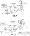
- FIG. 6is a simplified, schematic view of a cellular base station according to still further embodiments of the present invention.
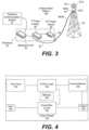
- FIG. 7is a simplified, schematic view of a cellular base station according to yet additional embodiments of the present invention.
- FIG. 8is a simplified, schematic view of a cellular base station according to yet further embodiments of the present invention.
- FIG. 9is a flow chart illustrating operations of methods according to embodiments of the present invention.
- a remote radio head (“RRH”) of a cellular base stationare provided, along with related cellular base stations and programmable power supplies. These methods, systems and power supplies may allow for lower power supply currents, which may reduce the power loss associated with delivering the DC power signal from the power supply at the base of a tower of the cellular base station to the RRH at the top of the tower. Since cellular towers may be hundreds of feet tall and the voltage and currents required to power the RRH may be quite high (e.g., about 50 Volts at about 20 Amperes of current), the power loss that may occur along the hundreds of feet of cabling may be significant. Thus, the methods according to embodiments of the present invention may provide significant power savings which may reduce the costs of operating a cellular base station.
- the electrical resistance R cable of the power cableis inversely proportional to the diameter of the conductor of the power cable (assuming a conductor having a circular cross-section).
- the larger the diameter of the conductori.e., the lower the gauge of the conductor
- the lower the resistance of the power cableTypically, power cables utilize copper conductors due to the low resistance of copper. Copper resistance is specified in terms of unit length, typically milliohms (m ⁇ )/ft; as such, the cumulative electrical resistance of the power cable increases with the length of the cable.
- the longer the power cablethe higher the voltage drop VDro p .
- V PSthe voltage output by the power supply
- the voltage output by the power supply(V PS ) is set to ensure that a power signal having the nominal voltage is supplied to the RRH (or at least a value above the minimum required voltage for the power signal) when the RRH draws the maximum anticipated amount of current.
- the power supplymay be set to output a DC power signal that, when it arrives at the RRH, will have the maximum voltage specified for the RRH, as the higher the voltage of the power signal that is delivered to the RRH the lower the current I RRH of the power signal on the power cable. As is apparent from Equation 3 above, the lower the current I RRH of the power signal on the power cable, the lower the power loss P Loss .
- the power supplymay comprise a programmable power supply which may (1) sense the current being drawn by the RRH (or another equivalent parameter) and (2) adjust the voltage of the power signal that is output by the power supply to substantially maintain the voltage of the power signal that is supplied to the RRH at or near a desired value, which may be, for example, the maximum voltage for the power signal that may be input to the RRH.
- a desired valuewhich may be, for example, the maximum voltage for the power signal that may be input to the RRH.
- the resistance of the power cablemay be input to the programmable power supply or, alternatively, other information such as, for example, the length and size of the power cable, or the impedance of the power cable, may be input to the programmable power supply and the programmable power supply may determine the resistance of the power cable from this information.
- the programmable power supplymay adjust the voltage of its output power signal to a voltage level that will deliver a power signal having a preselected voltage (e.g., the maximum supply voltage of the RRH minus a buffer) to the RRH. As shown by Equation 3 above, this will reduce or minimize the power loss along the power cable, and hence may reduce the cost of powering the RRH. As a typical RRH may require about a kilowatt of power and may run 24 hours a day, seven days a week, and as a large number of RRHs may be provided at each cellular base station (e.g., three to twelve), the power savings may be significant.
- a preselected voltagee.g., the maximum supply voltage of the RRH minus a buffer
- FIGS. 3 - 7in which example embodiments of the present invention are shown.
- FIG. 3is a schematic block diagram of a cellular base station 100 according to embodiments of the present invention.
- the cellular base station 100includes an equipment enclosure 20 and a tower 30 .
- the tower 30may be a conventional antenna or cellular tower or may be another structure such as a utility pole or the like.
- a baseband unit 22 , a first power supply 26 and a second power supply 28are located within the equipment enclosure 20 .
- An RRH 24 ′ and plurality of antennas 32(e.g., three sectorized antennas 32 - 1 , 32 - 2 , 32 - 3 ) are mounted on the tower 30 , typically near the top thereof.
- the RRH 24 ′receives digital information and control signals from the baseband unit 22 over a fiber optic cable 38 that is routed from the enclosure 20 to the top of the tower 30 .
- the RRH 24 ′modulates this information into a radio frequency (“RF”) signal at the appropriate cellular frequency that is then transmitted through one or more of the antennas 32 .
- the RRH 24 ′also receives RF signals from one or more of the antennas 32 , demodulates these signals, and supplies the demodulated signals to the baseband unit 22 over the fiber optic cable 38 .
- the baseband unit 22processes the demodulated signals received from the RRH 24 ′ and forwards the processed signals to the backhaul communications system 44 .
- the baseband unit 22also processes signals received from the backhaul communications system 44 and supplies them to the RRH 24 ′.
- the baseband unit 22 and the RRHs 24each include optical-to-electrical and electrical-to-optical converters that couple the digital information and control signals to and from the fiber optic cable 38 .
- the first power supply 26generates one or more direct current (“DC”) power signals.
- the second power supply 28 in the embodiment of FIG. 3comprises a DC-to-DC converter that accepts the DC power signal output by the first power supply 26 as an input and outputs a DC power signal having a different voltage.
- a power cable 36is connected to the output of the second power supply 28 and is bundled together with the fiber optic cable 38 so that the two cables 36 , 38 may be routed up the tower 30 as an integral unit. While the first power supply 26 and the second power supply 28 are illustrated as separate power supply units in the embodiment of FIG. 3 , it will be appreciated that the two power supplies 26 , 28 may be combined into a single power supply unit in other embodiments.
- the power supply 28comprises a programmable power supply that receives an input DC power signal from power supply 26 and outputs a DC power signal to the power cable 36 .
- the voltage of the DC power signal output by the power supply 28may vary in response to variations in the current of the DC power signal drawn from the power supply 28 by the RRH 24 ′.
- the voltage of the DC power signal output by the power supply 28may be set so that the voltage of the DC power signal at the far end of the power cable 36 (i.e., the end adjacent the RRH 24 ′) is relatively constant.
- the voltage of the DC power signal at the far end of power cable 36is set to be approximately the maximum specified voltage for the power signal of the RRH 24 ′, then the power loss associated with supplying the DC power signal to the RRH 24 ′ over the power cable 36 may be reduced, since the higher DC power signal voltage will correspondingly reduce the current of the DC power signal that is supplied over the power cable 36 .
- State-of-the-art RRHsare most typically designed to be powered by a 48 Volt (nominal) DC power signal. While the minimum DC power signal voltage at which the RRH 24 ′ will operate and the maximum DC power signal voltage that may be provided safely to the RRH 24 ′ without the threat of damage to the RRH 24 ′ vary, typical values are a 38 Volt minimum DC power signal voltage and a 56 Volt maximum DC power signal voltage.
- the programmable power supply 28may be designed to deliver a DC power signal having a relatively constant voltage of, for example, about 54 or 52 Volts at the far end of the power cable 36 (i.e., about, 2-4 Volts less than the maximum DC power signal voltage for the RRH 24 ′) in order to reduce the power loss associated with the voltage drop that the DC power signal experiences traversing the power cable 36 .
- the current of the DC power signal drawn from the power supplymust be known, as Equations 1 and 2 show that V RRH is a function of I RRH .
- the resistance R cable of the power cable 36must also be known, as it too affects the voltage drop.
- the programmable power supplies according to embodiments of the present inventionmay be configured to measure, estimate, calculate or receive both values.
- FIG. 4is a block diagram of a programmable power supply 150 in the form of a DC-to-DC converter according to certain embodiments of the present invention that may be used as the power supply 28 of FIG. 3 .
- the programmable power supply 150includes an input 152 , a conversion circuit 154 and an output 156 .
- the power supply 150further includes a current sensor 158 , a user input 160 , control logic 162 and a memory 164 .
- the input 152may receive a DC power signal such as the DC power signal output by power supply 26 of FIG. 3 .
- the DC power signal that is received at input 152may be a DC power signal having a relatively constant voltage in some embodiments.
- the conversion circuit 154may be a circuit that is configured to convert the voltage of the signal received at input 152 to a different DC voltage.
- a wide variety of DC conversion circuitsare known in the art, including, for example, electronic, electrochemical and electromechanical conversion circuits. Most typically electronic circuits using inductors or transformers are used to provide high efficiency voltage conversion.
- the output 156may output the DC power signal having the converted voltage.
- the current sensor 158may be any appropriate circuit that senses the current level of the DC power signal output through the output 156 .
- the current drawn by the RRH 24 ′may vary over time depending upon, for example, the number of carriers that are transmitting at any given time and whether the RRH is in a steady-state mode, powering up or rebooting.
- the current sensor 158may sense the current level of the DC power signal at output 156 and provide the sensed current level to the control logic 162 .
- the control logic 162may then adjust parameters of the conversion circuit 154 so as to adjust the voltage of the DC power signal output through output 156 so that the voltage at the far end of the power cable 36 that is attached to output 156 may remain substantially constant despite changes in the current drawn by the RRH 24 ′ and corresponding changes in the voltage drop that occurs over the power cable 36 .
- FIG. 4illustrates a power supply 150 that comprises a DC-to-DC converter
- the input 152receives an alternating current (“AC”) power signal and the conversion circuit 154 converts the AC power signal to a DC power signal and also adjusts the voltage level of the DC power signal that is output through output 156 to an appropriate level in the manner discussed above.
- ACalternating current
- the voltage of the power signal that is output by the power supply 150may be set so that the voltage at the far end of the power cable 36 remains at or near a predetermined voltage level that is just under a maximum power signal voltage level that the RRH 24 ′ may handle. In order to achieve this, it is necessary to know the voltage drop that the DC power signal will experience traversing the power cable 36 , as this voltage drop affects the voltage of the DC power signal at the far end of the power cable 36 .
- the user input 160 to the power supply 150allows a user to input a cumulative resistance value for the power cable 36 which the user may obtain by, for example, calculation (based on the length, size and material of the conductor of the power cable 36 ), measurement (done, for example, by transmitting a signal over the power cable 36 and measuring the voltage of the signal output at the far end of the power cable 36 ) or a combination thereof (e.g., measuring or estimating a cumulative impedance value for the power cable 36 and converting this cumulative impedance value into a cumulative resistance value).
- the usermay input physical characteristics of the power cable 36 such as size, length, conductor material, model number, etc.) and algorithms, equations, look-up tables and the like that are stored in the memory 164 of the power supply 150 may be used to calculate or estimate the resistance of the power cable 36 .
- the second power supply 28 of FIG. 3may further be configured to measure a resistance of the power cable 36 .
- FIG. 5is a block diagram of a programmable power supply 150 ′ according to further embodiments of the present invention that may be used to implement the power supply 28 of FIG. 3 .
- the power supply 150 ′is very similar to the power supply 150 of FIG. 4 , except that it further includes a cable resistance measurement circuit 170 that may be used to measure a resistance of the power supply cable.
- the cable resistance measurement circuit 170may be implemented in a variety of ways.
- the cable resistance measurement circuit 170may transmit a voltage pulse onto the power cable and measure the reflected return pulse (the far end of the power cable may be terminated with a termination having known characteristics). The current of the voltage pulse may be measured, as well as the voltage level of the reflected return pulse. The control logic 162 may then apply Ohm's law to calculate the resistance of the power cable. In other embodiments, at the far end of the power cable the two conductors thereof may be shorted and a voltage pulse may again be transmitted through the power cable. The current level of the pulse and the voltage level of the return pulse may be measured and the control logic 162 may again use these measured values to calculate the resistance of the power cable.
- the DC resistancecan be measured by transmitting alternating current signals at different frequencies over the power cable and measuring the amplitude and phase shift of these signals at the far end of the cable. The DC resistance may then be calculated using the measured results.
- Other ways of measuring the resistance of a wire segmentare known to those of skill in the art and may be used instead of the example methods listed above.
- the resistance measurement circuit 170may measure an impedance of the power cable and use this measured impedance value to determine the resistance of the power cable.
- the power supply 150 ′may alternatively comprise an AC-to-DC converter, similar to power supply 150 discussed above.
- Another technique for reducing the power loss associated with supplying power to a tower-mounted RRH of a cellular base stationis to dramatically increase the voltage of the DC power signal fed to the power cable that supplies the DC power signal to the RRH (i.e., well beyond the maximum voltage for the DC power signal that can be handled by the RRH), and then using a tower-mounted DC-to-DC converter power supply to step-down the voltage of the DC power signal to a voltage level that is appropriate for the RRH.
- the increased voltagereduces the current necessary to supply the wattage required by the RRH, the power loss along the power cable may be reduced (see Equation 2 above).
- FIG. 6is a simplified, schematic view of a cellular base station 200 that implements such a technique.
- the cellular base station 200is similar to the cellular base station 100 described above with reference to FIG. 3 , except that the cellular base station 200 further includes a third power supply 42 in the form of a tower-mounted DC-to-DC converter.
- the second power supply 28 of FIG. 3is omitted, and the first power supply 26 is configured to supply a DC power signal having a voltage that is significantly higher than the maximum voltage for the DC power signal that may be supplied to the RRH 24 ′ (e.g., a 150 volt DC power signal). This high voltage DC power signal may experience significantly less power loss when traversing the power cable 36 .
- the DC-to-DC converter 42is mounted at the top of the tower 30 between the far end of cable 36 and the RRH 24 ′.
- the DC-to-DC converter 42may be a Buck converter that decreases the voltage of the DC power signal received over the power cable 36 to a voltage level appropriate for supply to the RRH 24 ′.
- the second power supply 28may be included in the form of, for example, a DC-to-DC Boost power converter 28 that supplies a high voltage DC power signal (e.g., 150 volts) to the power cable 36 .
- a DC-to-DC converteris provided at both ends of the power cable 36 so that both of the above-described techniques for reducing power losses in the power cable 36 may be implemented.
- the second power supply 28may output a DC power signal having high voltage (e.g., on the order of 150 volts) that fluctuates with power requirements of the load so that the DC power signal that is supplied at the far end of power cable 36 is set at a relatively constant value.
- the tower-mounted DC-to-DC converter 42may be a simple device that down-converts the voltage of the DC power signal by a fixed amount X.
- FIGS. 6 and 7require the installation of additional equipment (i.e., the DC-to-DC converter 42 ) at the top of the tower 30 .
- additional equipmenti.e., the DC-to-DC converter 42
- the cost associated with sending a technician up a towermay be very high, there is generally a preference to reduce or minimize, where possible, the amount of equipment that is installed at the top of a cellular base station tower, and the equipment that is installed at the top of cellular towers tends to be expensive as it typically is designed to have very low failure rates and maintenance requirements in order to reduce the need for technician trips up the tower to service the equipment.
- the inclusion of an additional DC-to-DC converter 42also represents a further increase in capital expenditures, which must be weighed against the anticipated savings in operating costs.
- a DC power signalmay be supplied to a tower-mounted RRH (or other equipment) of a cellular base station over a power cable, where the DC power signal that is supplied to the RRH may have a relatively constant voltage level, regardless of the current drawn by the RRH.
- the voltage level of the DC power signal supplied to the RRHmay be set to be at or near a maximum power signal voltage that the RRH can handle, thereby reducing the power loss of the DC power signal. In this manner, the operating costs for the cellular base station may be reduced.
- the programmable power supply according to embodiments of the present inventionmay comprise a DC-to-DC converter that may be connected between a power supply of an existing base station and the power cable that supplies the power signal to a tower-mounted RRH.
- a DC-to-DC converterthat may be connected between a power supply of an existing base station and the power cable that supplies the power signal to a tower-mounted RRH.
- cellular base stationsinclude a first, conventional DC power supply 26 and a second DC-to-DC converter power supply 28 , it will be appreciated that in other embodiments these two power supplies may be replaced with a single programmable power supply that may be configured to output a relatively constant voltage at the far end of the power cable 36 in the manner described above.
- a feedback loopmay be used to control the voltage of the DC power signal output by the DC power supply so that the voltage of the DC power signal at the far end of the power cable that connects the power supply and the RRH is maintained at a desired level.
- FIG. 8is a simplified, schematic view of one example embodiment of a cellular base station 400 that implements such a technique.
- the cellular base station 400is similar to the cellular base station 100 described above with reference to FIG. 3 , except that the cellular base station 400 further includes a DC power signal voltage control module 50 that is co-located with the RRH 24 ′.
- the DC power signal voltage control module 50may be located, for example, at or near the top of the tower 30 .
- the DC power signal voltage control module 50may include a voltage meter 52 , a controller 54 and a communications module 56 .
- the voltage meter 52may be used to monitor the voltage of the DC power signal at the far end of the power cable 36 (i.e., at the top of the tower 30 ).
- Any appropriate voltage metermay be used that is capable of measuring the voltage of the DC power signal at the far end off cable 36 (or at another location proximate the RRH 24 ′) or that may measure other parameters which may be used to determine the voltage of the DC power signal at the far end off cable 36 .
- the voltage meter 52may supply the measured voltage (or other parameter) to the controller 54 .
- the controller 54may then control the communications module 56 to transmit the measured or calculated voltage of the DC power signal at the far end of power cable 36 to, for example, the second power supply 28 .
- the controller 54may comprise any appropriate processor, controller, ASIC, logic circuit or the like.
- the communications module 56may comprise a wired or wireless transmitter. In some embodiments, the communications module 56 may comprise a wireless Bluetooth transmitter or a cellular transmitter. In other embodiments, the communications module 56 may communicate with the second power supply 28 over a separate wired connection. In still other embodiments, the communications module 56 may communicate with the second power supply 28 by modulating a signal onto the power cable 36 .
- the communications module 56may transmit the measured or calculated voltage of the DC power signal at the far end of power cable 36 to the second power supply 28 .
- the second power supply 28may adjust the voltage of the DC power signal that it outputs in response to these communications in order to generally maintain the voltage of the DC power signal at the far end of power cable 36 at a desired and/or pre-selected level.
- an active feedback loopmay be used to maintain the voltage of the DC power signal at the far end of power cable 36 at the pre-selected level.
- the power signal voltage control module 50may be a standalone unit or may be integrated with other equipment such as, for example, the RRH 24 ′.
- an AC power signalmay be used instead.
- the power supply 28may output an AC power signal as opposed to a DC power signal, but may otherwise operate in the same fashion.
- an AC-to-DC convertermay be used instead or, if the RRH 24 ′ is designed to be powered by an AC power signal, the DC-to-DC converter 42 may be replaced with a Buck AC-to-AC converter.
- a single power cable 36has been provided that connects the power supply 28 to the RRH 24 ′. It will be appreciated, however, that the cabling connection for the power signal between the power supply 28 and the RRH 24 ′ may include multiple elements such as two or more power cables 36 that are connected by connectors in other embodiments.
- a method of powering a radio that is mounted on a tower of a cellular base stationwill now be described with reference to the flow chart of FIG. 9 .
- operationsmay begin with a user inputting information to a programmable power supply which may be used by the programmable power supply to set a voltage level of the power signal that is output by the programmable power supply (block 300 ).
- This informationmay comprise, for example, an electrical resistance of a cabling connection between the power supply and the radio or information regarding the characteristics of the cabling connection that may be used to calculate this resistance. While not shown in FIG.
- Embodiments of the present inventionprovide power supplies for powering radio equipment such as a remote radio head that is located remote from the power supply used to power the radio (e.g., the power supply is at the base of a cellular tower and the radio is at the top of the tower) without receiving any feedback from the radio or from other equipment at the remote location.
- the voltage of the DC power signal supplied by the power supply to the radio over a cabling connectionmay be set at a pre-selected level.
- the pre-selected levelmay be set to reduce or minimize power losses that may be incurred in transmitting the DC power signal over the cabling connection.
- the voltage of the DC power signal output by the power supplymay be varied based on variations in the current drawn from the power supply so that the voltage of the DC power signal at the radio end of the cabling connection may have, for example, a substantially constant value. This value may be selected to be near a maximum value for the voltage of the DC power signal that may be input to the radio.
- the voltage of the DC power signal output by the power supplywill be adjusted to maintain the voltage of the DC power signal at the radio end of the cabling connection at a set level, it will be appreciated that some variation is to be expected because of the time it takes the DC power supply to adjust the voltage of the DC power signal in response to changes in the current drawn. It will also be appreciated that the voltage of the DC power signal need not be maintained at a constant level at the radio end of the cabling connection but, may instead have different characteristics (e.g., set to be maintained within a predetermined range, set to return to a pre-selected level within a certain time period, etc.) in some embodiments.
- the voltage drop that occurs on the DC power signal that is delivered from a power supply located at the bottom of a cellular tower to the RRH at the top of the towermay be so large that the voltage of the DC power signal at the top of the tower may be insufficient to run the RRH.
- larger diameter power cablesare used in some cases that exhibit less DC resistance and hence a smaller voltage drop.
- the use of larger power cableshas a number of disadvantages, as these cables can be significantly more expensive, add more weight to the tower (requiring that the towers be constructed to handle this additional weight) and more difficult to install.
- this problemmay be reduced or solved by controlling the voltage of the DC power signal output by the power supply so that the voltage of the DC power signal at the radio end of the cabling connection may be at or near a maximum voltage for the DC power signal that may be input to the RRH.
- This schemereduces the voltage drop of the DC power signal, and hence may allow for the use of smaller diameter power cables and/or longer cabling connections between the power supply and the RRH. Additionally, as noted above, as the power losses experienced by the DC power signal are less, the costs of operating the RRH may also be reduced.
Landscapes
- Engineering & Computer Science (AREA)
- Signal Processing (AREA)
- Computer Networks & Wireless Communication (AREA)
- Electromagnetism (AREA)
- General Physics & Mathematics (AREA)
- Radar, Positioning & Navigation (AREA)
- Automation & Control Theory (AREA)
- Physics & Mathematics (AREA)
- Power Engineering (AREA)
- Cable Transmission Systems, Equalization Of Radio And Reduction Of Echo (AREA)
- Direct Current Feeding And Distribution (AREA)
- Remote Monitoring And Control Of Power-Distribution Networks (AREA)
- Transceivers (AREA)
Abstract
Description
VRRH=VPS−VDrop (1)
where VRRHis the DC voltage of the power signal delivered to the RRH, VPSis the DC voltage of the power signal that is output by the power supply, and VDropis the decrease in the DC voltage that occurs as the DC power signal traverses the power cable connecting the power supply to the RRH. VDropmay be determined according to Ohm's Law as follows:
VDrop=IRRH*RCable (2)
where Rcableis the cumulative electrical resistance (in Ohms) of the power cable connecting the power supply to the RRH and IRRHis the average current (in Amperes) flowing through the power cable to the RRH.
PLoss=VCable*IRRH=(IRRH*RCable)*IRRH=IRRH2*RCable (3)
where Vcable=the average voltage drop in Volts along the power cable. In order to reduce or minimize PLoss, the power supply may be set to output a DC power signal that, when it arrives at the RRH, will have the maximum voltage specified for the RRH, as the higher the voltage of the power signal that is delivered to the RRH the lower the current IRRHof the power signal on the power cable. As is apparent from Equation 3 above, the lower the current IRRHof the power signal on the power cable, the lower the power loss PLoss.
Voltage of Delivered Power Signal=VRRH-Max−Vmargin+X (4)
where VRRH-Maxis the maximum power signal voltage that the
Claims (17)
Priority Applications (1)
| Application Number | Priority Date | Filing Date | Title |
|---|---|---|---|
| US16/931,747US11662759B2 (en) | 2014-02-17 | 2020-07-17 | Programmable power supplies for cellular base stations and related methods of reducing power loss in cellular systems |
Applications Claiming Priority (6)
| Application Number | Priority Date | Filing Date | Title |
|---|---|---|---|
| US201461940631P | 2014-02-17 | 2014-02-17 | |
| US14/321,897US9448576B2 (en) | 2014-02-17 | 2014-07-02 | Programmable power supplies for cellular base stations and related methods of reducing power loss in cellular systems |
| US15/226,977US10025335B2 (en) | 2014-02-17 | 2016-08-03 | Programmable power supplies for cellular base stations and related methods of reducing power loss in cellular systems |
| US15/898,809US11275395B2 (en) | 2014-02-17 | 2018-02-19 | Programmable power supplies for cellular base stations and related methods of reducing power loss in cellular systems |
| US16/380,907US11675381B2 (en) | 2014-02-17 | 2019-04-10 | Apparatuses and related methods for reducing power loss |
| US16/931,747US11662759B2 (en) | 2014-02-17 | 2020-07-17 | Programmable power supplies for cellular base stations and related methods of reducing power loss in cellular systems |
Related Parent Applications (1)
| Application Number | Title | Priority Date | Filing Date |
|---|---|---|---|
| US16/380,907ContinuationUS11675381B2 (en) | 2014-02-17 | 2019-04-10 | Apparatuses and related methods for reducing power loss |
Publications (2)
| Publication Number | Publication Date |
|---|---|
| US20200348709A1 US20200348709A1 (en) | 2020-11-05 |
| US11662759B2true US11662759B2 (en) | 2023-05-30 |
Family
ID=53798090
Family Applications (17)
| Application Number | Title | Priority Date | Filing Date |
|---|---|---|---|
| US14/321,897Active2034-08-25US9448576B2 (en) | 2014-02-17 | 2014-07-02 | Programmable power supplies for cellular base stations and related methods of reducing power loss in cellular systems |
| US15/226,977ActiveUS10025335B2 (en) | 2014-02-17 | 2016-08-03 | Programmable power supplies for cellular base stations and related methods of reducing power loss in cellular systems |
| US15/497,021ActiveUS10394265B2 (en) | 2014-02-17 | 2017-04-25 | Programmable power supplies for cellular base stations and related methods of reducing power loss in cellular systems |
| US15/898,573ActiveUS10423180B2 (en) | 2014-02-17 | 2018-02-17 | Programmable power supplies for cellular base stations and related methods of reducing power loss in cellular systems |
| US15/898,809ActiveUS11275395B2 (en) | 2014-02-17 | 2018-02-19 | Programmable power supplies for cellular base stations and related methods of reducing power loss in cellular systems |
| US16/163,958ActiveUS11256277B2 (en) | 2014-02-17 | 2018-10-18 | Programmable power supplies for cellular base stations and related methods of reducing power loss in cellular systems |
| US16/380,921ActiveUS10782720B2 (en) | 2014-02-17 | 2019-04-10 | Programmable power supplies for cellular base stations and related methods of reducing power loss in cellular systems |
| US16/380,907ActiveUS11675381B2 (en) | 2014-02-17 | 2019-04-10 | Apparatuses and related methods for reducing power loss |
| US16/931,747Active2034-07-14US11662759B2 (en) | 2014-02-17 | 2020-07-17 | Programmable power supplies for cellular base stations and related methods of reducing power loss in cellular systems |
| US16/931,734Active2034-07-20US11669117B2 (en) | 2014-02-17 | 2020-07-17 | Programmable power supplies for cellular base stations and related methods of reducing power loss in cellular systems |
| US16/994,809ActiveUS11669118B2 (en) | 2014-02-17 | 2020-08-17 | Programmable power supplies for cellular base stations and related methods of reducing power loss in cellular systems |
| US17/099,121Active2034-10-16US11675382B2 (en) | 2014-02-17 | 2020-11-16 | Programmable power supplies for cellular base stations and related methods of reducing power loss in cellular systems |
| US17/100,702Active2034-09-29US11740645B2 (en) | 2014-02-17 | 2020-11-20 | Programmable power supplies for cellular base stations and related methods of reducing power loss in cellular systems |
| US17/849,216PendingUS20220317716A1 (en) | 2014-02-17 | 2022-06-24 | Programmable power supplies for cellular base stations and related methods of reducing power loss in cellular system |
| US17/849,203PendingUS20220317715A1 (en) | 2014-02-17 | 2022-06-24 | Programmable power supplies for cellular base stations and related methods of reducing power loss in cellular systems |
| US18/194,857PendingUS20230236617A1 (en) | 2014-02-17 | 2023-04-03 | Programmable power supplies for cellular base stations and related methods of reducing power loss in cellular systems |
| US18/301,710PendingUS20230251681A1 (en) | 2014-02-17 | 2023-04-17 | Programmable power supplies for cellular base stations and related methods of reducing power loss in cellular systems |
Family Applications Before (8)
| Application Number | Title | Priority Date | Filing Date |
|---|---|---|---|
| US14/321,897Active2034-08-25US9448576B2 (en) | 2014-02-17 | 2014-07-02 | Programmable power supplies for cellular base stations and related methods of reducing power loss in cellular systems |
| US15/226,977ActiveUS10025335B2 (en) | 2014-02-17 | 2016-08-03 | Programmable power supplies for cellular base stations and related methods of reducing power loss in cellular systems |
| US15/497,021ActiveUS10394265B2 (en) | 2014-02-17 | 2017-04-25 | Programmable power supplies for cellular base stations and related methods of reducing power loss in cellular systems |
| US15/898,573ActiveUS10423180B2 (en) | 2014-02-17 | 2018-02-17 | Programmable power supplies for cellular base stations and related methods of reducing power loss in cellular systems |
| US15/898,809ActiveUS11275395B2 (en) | 2014-02-17 | 2018-02-19 | Programmable power supplies for cellular base stations and related methods of reducing power loss in cellular systems |
| US16/163,958ActiveUS11256277B2 (en) | 2014-02-17 | 2018-10-18 | Programmable power supplies for cellular base stations and related methods of reducing power loss in cellular systems |
| US16/380,921ActiveUS10782720B2 (en) | 2014-02-17 | 2019-04-10 | Programmable power supplies for cellular base stations and related methods of reducing power loss in cellular systems |
| US16/380,907ActiveUS11675381B2 (en) | 2014-02-17 | 2019-04-10 | Apparatuses and related methods for reducing power loss |
Family Applications After (8)
| Application Number | Title | Priority Date | Filing Date |
|---|---|---|---|
| US16/931,734Active2034-07-20US11669117B2 (en) | 2014-02-17 | 2020-07-17 | Programmable power supplies for cellular base stations and related methods of reducing power loss in cellular systems |
| US16/994,809ActiveUS11669118B2 (en) | 2014-02-17 | 2020-08-17 | Programmable power supplies for cellular base stations and related methods of reducing power loss in cellular systems |
| US17/099,121Active2034-10-16US11675382B2 (en) | 2014-02-17 | 2020-11-16 | Programmable power supplies for cellular base stations and related methods of reducing power loss in cellular systems |
| US17/100,702Active2034-09-29US11740645B2 (en) | 2014-02-17 | 2020-11-20 | Programmable power supplies for cellular base stations and related methods of reducing power loss in cellular systems |
| US17/849,216PendingUS20220317716A1 (en) | 2014-02-17 | 2022-06-24 | Programmable power supplies for cellular base stations and related methods of reducing power loss in cellular system |
| US17/849,203PendingUS20220317715A1 (en) | 2014-02-17 | 2022-06-24 | Programmable power supplies for cellular base stations and related methods of reducing power loss in cellular systems |
| US18/194,857PendingUS20230236617A1 (en) | 2014-02-17 | 2023-04-03 | Programmable power supplies for cellular base stations and related methods of reducing power loss in cellular systems |
| US18/301,710PendingUS20230251681A1 (en) | 2014-02-17 | 2023-04-17 | Programmable power supplies for cellular base stations and related methods of reducing power loss in cellular systems |
Country Status (6)
| Country | Link |
|---|---|
| US (17) | US9448576B2 (en) |
| EP (2) | EP3826194B1 (en) |
| CN (3) | CN105981307B (en) |
| AU (4) | AU2015217537B2 (en) |
| ES (1) | ES2906561T3 (en) |
| WO (1) | WO2015123036A1 (en) |
Cited By (1)
| Publication number | Priority date | Publication date | Assignee | Title |
|---|---|---|---|---|
| US12072721B2 (en) | 2014-02-17 | 2024-08-27 | Commscope Technologies Llc | Methods and equipment for reducing power loss in cellular systems |
Families Citing this family (40)
| Publication number | Priority date | Publication date | Assignee | Title |
|---|---|---|---|---|
| US11251608B2 (en) | 2010-07-13 | 2022-02-15 | Raycap S.A. | Overvoltage protection system for wireless communication systems |
| US8780519B2 (en) | 2011-02-08 | 2014-07-15 | Raycap, S.A. | Modular and weather resistant overvoltage protection system for wireless communication systems |
| US9759880B2 (en) | 2013-09-17 | 2017-09-12 | Commscope Technologies Llc | Capacitive-loaded jumper cables, shunt capacitance units and related methods for enhanced power delivery to remote radio heads |
| US10712515B2 (en) | 2013-09-17 | 2020-07-14 | Commscope Technologies Llc | Capacitive-loaded jumper cables, shunt capacitance units and related methods for enhanced power delivery to remote radio heads |
| US9640986B2 (en) | 2013-10-23 | 2017-05-02 | Raycap Intellectual Property Ltd. | Cable breakout assembly |
| US10830803B2 (en) | 2014-02-17 | 2020-11-10 | Commscope Technologies Llc | Methods and equipment for reducing power loss in cellular systems |
| US9448576B2 (en) | 2014-02-17 | 2016-09-20 | Commscope Technologies Llc | Programmable power supplies for cellular base stations and related methods of reducing power loss in cellular systems |
| US11333695B2 (en) | 2014-02-17 | 2022-05-17 | Commscope Technologies Llc | Methods and equipment for reducing power loss in cellular systems |
| CN105822125B (en)* | 2015-01-04 | 2018-07-31 | 华为技术有限公司 | A kind of base station |
| JP2016225921A (en)* | 2015-06-02 | 2016-12-28 | 富士通株式会社 | Gwangdeung radio equipment |
| US10802237B2 (en) | 2015-11-03 | 2020-10-13 | Raycap S.A. | Fiber optic cable management system |
| US9971119B2 (en) | 2015-11-03 | 2018-05-15 | Raycap Intellectual Property Ltd. | Modular fiber optic cable splitter |
| CN107181252A (en)* | 2016-03-11 | 2017-09-19 | 华为技术有限公司 | Power supply control apparatus, electric power system, load and base station |
| US10128685B2 (en)* | 2016-05-11 | 2018-11-13 | Commscope Technologies Llc | Methods and equipment for providing backup power in cellular base stations |
| WO2018136812A1 (en)* | 2017-01-20 | 2018-07-26 | Raycap S.A. | Power transmission system for wireless communication systems |
| WO2018169586A1 (en)* | 2017-03-16 | 2018-09-20 | Commscope Technologies Llc | Methods and appartus for determing cable resistance |
| WO2018191269A1 (en)* | 2017-04-10 | 2018-10-18 | Vertiv Energy Systems, Inc. | Dc-dc converters having bullet terminals |
| US10396844B2 (en) | 2017-05-22 | 2019-08-27 | Commscope Technologies Llc | Method and apparatus for converting DC voltages at the top of a telecommunications tower |
| US10541531B2 (en) | 2017-05-22 | 2020-01-21 | Commscope Technologies Llc | Method and apparatus for converting DC voltages at the top of a telecommunications tower |
| US11129095B2 (en) | 2017-06-15 | 2021-09-21 | John Mezzalingua Associates, LLC | Controller for precisely powering remote radio heads on a cell tower |
| US11102665B2 (en) | 2018-02-23 | 2021-08-24 | T-Mobile Usa, Inc. | Supplemental voltage controller for radio frequency (RF) antennas |
| US10868471B2 (en) | 2018-02-23 | 2020-12-15 | T-Mobile Usa, Inc. | Adaptive voltage modification (AVM) controller for mitigating power interruptions at radio frequency (RF) antennas |
| US10470120B2 (en)* | 2018-03-14 | 2019-11-05 | T-Mobile Usa, Inc. | Power compensator for cellular communication base station |
| US10971928B2 (en) | 2018-08-28 | 2021-04-06 | Raycap Ip Assets Ltd | Integrated overvoltage protection and monitoring system |
| JP7191083B2 (en)* | 2018-09-30 | 2022-12-16 | オッポ広東移動通信有限公司 | Charging device test board, test system and test method |
| WO2020105176A1 (en)* | 2018-11-22 | 2020-05-28 | 三菱電機株式会社 | Power conversion system |
| WO2020223452A1 (en)* | 2019-05-01 | 2020-11-05 | Commscope Technologies Llc | Methods and equipment for reducing power loss in cellular systems |
| US11677164B2 (en) | 2019-09-25 | 2023-06-13 | Raycap Ip Assets Ltd | Hybrid antenna distribution unit |
| US11849390B2 (en) | 2020-03-20 | 2023-12-19 | Dish Wireless L.L.C. | Method and system for power management based on full RF conditions |
| US12301107B2 (en) | 2021-02-16 | 2025-05-13 | Outdoor Wireless Networks LLC | Methods and equipment for reducing power loss in radio systems |
| WO2022187095A1 (en)* | 2021-03-05 | 2022-09-09 | Commscope Technologies Llc | Efficient installation and configuration of voltage conversion systems |
| US12429507B2 (en)* | 2021-03-05 | 2025-09-30 | Outdoor Wireless Networks LLC | System and method for determining cable resistance using at least one electrical parameter measured by a radio |
| CN113659699A (en)* | 2021-08-17 | 2021-11-16 | 王良根 | Emergency power supply intelligent control method and system for base station |
| US12237134B2 (en) | 2021-12-28 | 2025-02-25 | Raycap Ip Assets Ltd | Circuit protection for hybrid antenna distribution units |
| US12379760B2 (en) | 2022-02-28 | 2025-08-05 | Raycap, S.A. | Automatic circuit allocation of remote devices in a multi-power supply system |
| WO2023161721A1 (en)* | 2022-02-28 | 2023-08-31 | Raycap, S.A. | Automatic circuit allocation of remote devices in a multi-power supply system |
| WO2024006047A1 (en) | 2022-07-01 | 2024-01-04 | Commscope Technologies Llc | Systems and methods for providing voltage boosting to a time domain duplexing radio |
| WO2024003952A2 (en) | 2022-07-01 | 2024-01-04 | Commscope Technologies Llc | Techniques for associating a feedback port or electrical conductor resistance with a dc output port of a voltage converter system |
| IT202300012564A1 (en) | 2023-06-19 | 2024-12-19 | Commscope Technologies Llc | SYSTEM AND METHOD FOR DETECTING ELECTRICALLY CONNECTED OUTPUTS OF DIFFERENT VOLTAGE CONVERTERS |
| WO2025101240A1 (en) | 2023-11-08 | 2025-05-15 | Outdoor Wireless Networks LLC | Selective voltage boosting for a radio system |
Citations (121)
| Publication number | Priority date | Publication date | Assignee | Title |
|---|---|---|---|---|
| US3659189A (en) | 1971-02-03 | 1972-04-25 | Forbro Design Corp | Regulated power supply lead-drop compensation |
| US4745562A (en) | 1985-08-16 | 1988-05-17 | Schlumberger, Limited | Signal processing disparity resolution |
| US5073977A (en) | 1987-08-19 | 1991-12-17 | Murata Manufacturing Co., Ltd. | High frequency broad-band mixing circuit including an electrolytic capacitor in parallel with a local oscillator input port |
| JPH06163330A (en) | 1992-11-20 | 1994-06-10 | Rohm Co Ltd | Structure of molded solid electrolytic capacitor |
| US5548813A (en) | 1994-03-24 | 1996-08-20 | Ericsson Inc. | Phased array cellular base station and associated methods for enhanced power efficiency |
| US5610793A (en) | 1994-07-22 | 1997-03-11 | Pacusma Co. Ltd. | No-MOV protection circuitry |
| US6095867A (en) | 1998-09-21 | 2000-08-01 | Rockwell Technologies, Llc | Method and apparatus for transmitting power and data signals via a network connector system including integral power capacitors |
| US6125048A (en) | 1998-12-28 | 2000-09-26 | Lucent Technologies, Inc. | Method and apparatus for adjusting power delivered from a central power unit to a remote unit via a supply cable |
| US6188566B1 (en) | 1998-08-14 | 2001-02-13 | Rohm Co., Ltd. | Solid electrolytic capacitor having a second lead with a throughhole filled with an arc-extinguishing material |
| WO2001067598A1 (en) | 2000-03-10 | 2001-09-13 | Paragon Communications Ltd. | Method and apparatus for improving the efficiency of power amplifiers, operating under a large peak-to-average ratio |
| US20010025349A1 (en) | 2000-01-07 | 2001-09-27 | Sharood John N. | Retrofit monitoring device |
| US6517967B1 (en)* | 1998-12-15 | 2003-02-11 | Electric Fuel Limited | Battery pack design for metal-air battery cells |
| US20030085621A1 (en) | 1997-11-17 | 2003-05-08 | Potega Patrick Henry | Power supply methods and configurations |
| US6640111B1 (en) | 1997-03-03 | 2003-10-28 | Celletra Ltd. | Cellular communications systems |
| US20040121807A1 (en) | 2002-12-20 | 2004-06-24 | Alcatel | Fixed transmitting station with electromagnetic field probe |
| US6813510B1 (en) | 2000-01-11 | 2004-11-02 | Lucent Technologies Inc. | System for automatically adjusting receive path gain |
| US20040223346A1 (en) | 2003-05-07 | 2004-11-11 | Toshiba International Corporation | Circuit with DC link fuse |
| US20040251968A1 (en) | 2003-04-25 | 2004-12-16 | Israel Bar-David | Method and apparatus for providing a stable power output of power amplifiers, operating under unstable supply voltage conditions |
| US20050242882A1 (en)* | 2004-04-28 | 2005-11-03 | Anderson William D | Wireless terminals, methods and computer program products with transmit power amplifier input power regulation |
| US20050281063A1 (en) | 2004-06-16 | 2005-12-22 | Nokia Corporation | Phone energy management for low battery voltages |
| US20060005055A1 (en) | 1998-12-31 | 2006-01-05 | Potega Patrick H | Requirements for supplying power to a device |
| US7027290B1 (en) | 2003-11-07 | 2006-04-11 | Maxwell Technologies, Inc. | Capacitor heat reduction apparatus and method |
| US20060076946A1 (en) | 2004-10-12 | 2006-04-13 | Eaton Corporation | Self-powered power bus sensor employing wireless communication |
| US20060077046A1 (en) | 2004-10-06 | 2006-04-13 | Canon Kabushiki Kaisha | Power-line communication device |
| US20060164108A1 (en) | 2005-01-25 | 2006-07-27 | Linear Technology Corporation | System for providing power over communication cable having mechanism for determining resistance of communication cable |
| US20060216837A1 (en) | 2005-03-25 | 2006-09-28 | Tdk Corporation | Method and apparatus for testing tunnel magnetoresistive effect element, manufacturing method of tunnel magnetoresistive effect element and tunnel magnetoresistive effect element |
| US20070024372A1 (en) | 2005-07-14 | 2007-02-01 | Rodney Hagen | Method and apparatus for controlling a power amplifier supply voltage |
| US20070093204A1 (en) | 2004-07-16 | 2007-04-26 | Dwayne Kincard | Control system |
| CN101043239A (en) | 2007-04-28 | 2007-09-26 | 华为技术有限公司 | System for biasing T-shaped head and controlling antenna |
| US20070263675A1 (en) | 2006-04-13 | 2007-11-15 | Cisco Technology, Inc. | Method and apparatus for current sharing ethernet power across four conductor pairs using a midspan device |
| US20080010474A1 (en) | 2002-12-21 | 2008-01-10 | Power-One, Inc. | Method And System For Optimizing Filter Compensation Coefficients For A Digital Power Control System |
| US20080030078A1 (en) | 2006-06-01 | 2008-02-07 | Exaflop Llc | Data Center Uninterruptible Power Distribution Architecture |
| CN201075824Y (en) | 2007-08-14 | 2008-06-18 | 青岛海信电器股份有限公司 | Antenna feeding circuit |
| US20080172564A1 (en) | 2007-01-16 | 2008-07-17 | Broadcom Corporation | System and method for controlling a power budget at a power source equipment using a PHY |
| US20080272654A1 (en) | 2007-04-26 | 2008-11-06 | Lontka Karen D | Methods and apparatus for providing power to a notification appliance circuit |
| US7460381B2 (en) | 1994-04-26 | 2008-12-02 | Comarco Wireless Technologies, Inc. | Programmable power supply |
| US20080300003A1 (en) | 2004-07-06 | 2008-12-04 | Michael Jeck | Aligning Radio Base Station Node Transmission Timing on Multiple Transmit Paths |
| US7508687B2 (en) | 2005-08-03 | 2009-03-24 | Mihai-Costin Manolescu | Power supply that reads power requirement information across a DC power cord from a load |
| US20090215492A1 (en) | 2008-02-25 | 2009-08-27 | Vodafone Holding Gmbh | Mobile radio station and hybrid cable for a mobile radio station |
| US20090258652A1 (en) | 2001-05-02 | 2009-10-15 | Thomas Lambert | Cellular systems with distributed antennas |
| US20090289637A1 (en) | 2007-11-07 | 2009-11-26 | Radtke William O | System and Method for Determining the Impedance of a Medium Voltage Power Line |
| KR20100048227A (en) | 2008-10-30 | 2010-05-11 | 주식회사 케이티 | Mobile communication relay system, tower top amplifier and high power amplifier |
| US7739522B2 (en) | 2003-10-24 | 2010-06-15 | Nera Asa | Efficient power supply for rapidly changing power requirements |
| KR20100069332A (en) | 2008-12-16 | 2010-06-24 | 이은철 | Base station towertop wireless transmitter-receiver and base station system |
| US20100181840A1 (en) | 2009-01-16 | 2010-07-22 | Cambridge Semiconductor Limited | Cable compensation |
| USRE41655E1 (en) | 2001-02-15 | 2010-09-07 | David Woodhead | System and method of automatically calibrating the gain for a distributed wireless communication system |
| US20100237948A1 (en) | 2007-02-16 | 2010-09-23 | Microelectronic Technologies, Inc. | System and method for dynamic drain voltage adjustment to control linearity, output power, and efficiency in rf power amplifiers |
| CN101848004A (en) | 2008-12-02 | 2010-09-29 | 美国博通公司 | Configurable receiver, transmitter, transceiver and methods for use therewith |
| US20100290787A1 (en) | 2009-05-15 | 2010-11-18 | Cox Terry D | Power Distribution Devices, Systems, and Methods for Radio-Over-Fiber (RoF) Distributed Communication |
| US20100301669A1 (en)* | 2009-05-26 | 2010-12-02 | Bae Systems Information And Electronic Systems Integration Inc. | Power management for power constrained devices |
| US7894782B2 (en) | 2007-09-06 | 2011-02-22 | Broadcom Corporation | Multi-input multi-output transceiver with transmit power management based on receiver parameter and method for use therewith |
| US20110053632A1 (en) | 2009-08-25 | 2011-03-03 | Jigang Liu | Antenna transmitting power monitoring and/or controlling |
| KR20110024543A (en) | 2009-09-02 | 2011-03-09 | 주식회사 케이엠더블유 | Tower mounted booster |
| CN201789332U (en) | 2010-08-06 | 2011-04-06 | 深圳市金威源科技股份有限公司 | Power supply system of communication base station |
| US20110101937A1 (en) | 2009-10-30 | 2011-05-05 | Linear Technology Corporation | Voltage Regulator with Virtual Remote Sensing |
| US7949315B2 (en) | 2007-09-25 | 2011-05-24 | Broadcom Corporation | Power consumption management and data rate control based on transmit power and method for use therewith |
| US20110159877A1 (en) | 2009-12-29 | 2011-06-30 | Peter Kenington | Active antenna array with multiple amplifiers for a mobile communications network and method of providing dc voltage to at least one processing element |
| US20110237299A1 (en) | 2008-11-27 | 2011-09-29 | Michael Boss | Gps mast module and mobile radio installation |
| US20120069882A1 (en) | 2008-05-21 | 2012-03-22 | Public Wireless, Inc. | Messenger strand mounted pico-cell radio |
| CN102439835A (en) | 2011-10-09 | 2012-05-02 | 华为技术有限公司 | Wireless distributed base station power supply system |
| US20120146576A1 (en)* | 2010-06-11 | 2012-06-14 | Mojo Mobility, Inc. | System for wireless power transfer that supports interoperability, and multi-pole magnets for use therewith |
| US20120155120A1 (en) | 2010-12-17 | 2012-06-21 | Fujitsu Limited | Power supply unit and an information processing apparatus |
| US20120181878A1 (en) | 2009-09-30 | 2012-07-19 | Panasonic Corporation | Direct current power line communication system and direct current power line communication apparatus |
| US20120223575A1 (en) | 2011-03-01 | 2012-09-06 | Omron Automotive Electronics Co., Ltd. | Power conversion apparatus and power control method |
| CN102680799A (en) | 2012-05-15 | 2012-09-19 | 山东惠工电气股份有限公司 | Transformer substation capacitor on-line monitoring method and device based on wireless mode |
| US20120235636A1 (en) | 2011-01-18 | 2012-09-20 | Afshin Partovi | Systems and methods for providing positioning freedom, and support of different voltages, protocols, and power levels in a wireless power system |
| CN102752885A (en) | 2011-04-21 | 2012-10-24 | 泰科电子荷兰公司 | Remote electronic component, remote electronic component array and external distributor unit |
| US20120269509A1 (en) | 2011-04-21 | 2012-10-25 | Antonius Petrus Hultermans | Remote Electronic Component, Such As Remote Radio Head, For A Wireless Communication System, Remote Electronic Component Array And External Distributor Unit |
| US8311591B2 (en) | 2009-05-13 | 2012-11-13 | Alcatel Lucent | Closed-loop efficiency modulation for use in network powered applications |
| CA2836133A1 (en) | 2011-05-17 | 2012-11-22 | 3M Innovative Properties Company | Converged in-building network |
| US20120295670A1 (en) | 2007-09-24 | 2012-11-22 | Broadcom Corporation | Power consumption management in a mimo transceiver and method for use therewith |
| WO2012159358A1 (en) | 2011-08-01 | 2012-11-29 | 华为技术有限公司 | Lightning protection radio remote unit, distributed base station and lightning protection system and method thereof |
| US20120317426A1 (en) | 2011-06-09 | 2012-12-13 | Andrew Llc | Distributed antenna system using power-over-ethernet |
| US20130034949A1 (en) | 2011-08-05 | 2013-02-07 | United Microelectronics Corp. | Method of forming trench isolation |
| US8401501B2 (en) | 2007-01-30 | 2013-03-19 | Broadcom Corporation | Transmit power management for a communication device and method for use therewith |
| US8401497B2 (en) | 2008-12-02 | 2013-03-19 | Broadcom Corporation | Configurable RF sections for receiver and transmitter and methods for use therewith |
| US8412385B2 (en) | 2004-12-15 | 2013-04-02 | Silego Technology, Inc. | Power management |
| US20130082667A1 (en)* | 2010-03-24 | 2013-04-04 | Mark Sinreich | Power management circuit for wireless communication device and process control system using same |
| US20130108227A1 (en) | 2011-10-26 | 2013-05-02 | Mark Edward Conner | Composite cable breakout assembly |
| US20130215804A1 (en) | 2010-12-13 | 2013-08-22 | Telefonaktiebolaget L M Ericsson (Publ) | Base Station Subsystem, a RBS Part and a TMA Part and Methods Thereof for Synchronizing the RBS Part and the TMA Part |
| US8526893B2 (en) | 2008-12-02 | 2013-09-03 | Broadcom Corporation | Power management unit for configurable receiver and transmitter and methods for use therewith |
| US8547164B2 (en) | 2010-09-28 | 2013-10-01 | Texas Instruments Incorporated | Closed loop adaptive voltage scaling |
| US20130260702A1 (en) | 2012-04-02 | 2013-10-03 | Peter Kenington | Active antenna array and method for transmitting radio signal |
| WO2013147332A1 (en) | 2012-03-27 | 2013-10-03 | 스마트파이 주식회사 | Cable and compensation method for transmitting high speed signal and delivering power |
| US8566627B2 (en) | 2000-01-18 | 2013-10-22 | Sameer Halepete | Adaptive power control |
| US8577359B2 (en) | 2002-05-21 | 2013-11-05 | M2M Solutions Llc | System and method for remote asset management |
| US20130314069A1 (en) | 2012-05-24 | 2013-11-28 | Sony Corporation | Power supply device, adapter, power receiving device, and power supply method |
| US20130328539A1 (en) | 2012-06-07 | 2013-12-12 | Robert Dean King | System for transferring energy from an energy source and method of making same |
| US20140055898A1 (en)* | 2012-08-22 | 2014-02-27 | Raycap Corporation | Devices and Methods for Overvoltage Protection |
| US20140132169A1 (en) | 2011-04-20 | 2014-05-15 | Koninklijke Philips N.V. | Controlled converter architecture with prioritized electricity supply |
| US20140132192A1 (en) | 2012-11-13 | 2014-05-15 | Schlumberger Technology Corporation | Power control for electrical applications over long cables |
| US20140159506A1 (en) | 2012-12-12 | 2014-06-12 | Samsung Electronics Co., Ltd. | Power conversion apparatus including multiple dc-dc converters and method of controlling multiple dc-dc converters |
| US20140168842A1 (en) | 2012-12-10 | 2014-06-19 | Raycap Intellectual Property Ltd. | Overvoltage protection and monitoring system |
| US20140204496A1 (en) | 2013-01-22 | 2014-07-24 | Corning Cable Systems Llc | Rack-mountable, tiltable surge protector housings for power surge protector accessibility, and related assemblies, methods, and base station equipment |
| US20140204497A1 (en) | 2013-01-22 | 2014-07-24 | Corning Cable Systems Llc | Rack-mountable surge protector housings having translatable surge protector trays for power surge protector accessibility, and related assemblies, methods, and base station equipment |
| CN104067443A (en) | 2012-01-27 | 2014-09-24 | 株式会社Kmw | Antenna system of mobile communication base station |
| US8848766B2 (en) | 2010-08-17 | 2014-09-30 | Dali Systems Co. Ltd. | Neutral host architecture for a distributed antenna system |
| US20140372258A1 (en) | 2013-06-13 | 2014-12-18 | Elbex Video Ltd. | Method and Apparatus for Propagating Combination of Signals for Operating a Closed Circuit E-Commerce |
| US20150006095A1 (en) | 2013-06-28 | 2015-01-01 | Landis+Gyr, Inc. | Element Resistance Measurement in an Electricity Meter |
| CN104335294A (en) | 2012-05-22 | 2015-02-04 | 瑞典爱立信有限公司 | Cable for powering of mast mounted radio equipment |
| US20150058652A1 (en) | 2013-08-20 | 2015-02-26 | Electronic Systems Protection, Inc. | Network Appliance with Power Conditioning |
| US20150080055A1 (en) | 2013-09-17 | 2015-03-19 | Andrew Llc | Methods for enhanced power delivery to tower-mounted and other remotely-mounted remote radio heads and related systems and power cables |
| US20150089253A1 (en)* | 2013-09-26 | 2015-03-26 | International Business Machines Corporation | Power Converter for a Computer Device and Method for Operating a Power Converter |
| US20150097518A1 (en) | 2012-05-03 | 2015-04-09 | Poweroasis Limited | Hybrid battery control |
| US20150137987A1 (en) | 2012-07-12 | 2015-05-21 | Halliburton Energy Services, Inc. | Joint time-frequency processing for borehole acoustic arrays |
| US20150155669A1 (en) | 2013-09-17 | 2015-06-04 | Andrew Llc | Capacitive-loaded jumper cables, shunt capacitance units and related methods for enhanced power delivery to remote radio heads |
| US20150168974A1 (en) | 2013-12-16 | 2015-06-18 | At&T Mobility Ii Llc | Systems, Methods, and Computer Readable Storage Device for Delivering Power to Tower Equipment |
| US20150234405A1 (en) | 2014-02-17 | 2015-08-20 | Andrew Llc | Programmable Power Supplies for Cellular Base Stations and Related Methods of Reducing Power Loss in Cellular Systems |
| US20150234399A1 (en) | 2014-02-17 | 2015-08-20 | Commscope Technologies Llc | Methods and equipment for reducing power loss in cellular systems |
| US20150256062A1 (en) | 2012-10-23 | 2015-09-10 | Mitsubishi Electric Engineering Company, Limited | Power source control device and method for controlling power source control device |
| US20150326317A1 (en) | 2014-05-12 | 2015-11-12 | Commscope Technologies Llc | Remote radio heads having wireless jumper connections and related equipment, systems and methods |
| US20150382293A1 (en) | 2010-10-13 | 2015-12-31 | Ccs Technology, Inc. | Local power management for remote antenna units in distributed antenna systems |
| US9374179B2 (en) | 2007-08-20 | 2016-06-21 | Telefonaktiebolaget Lm Ericsson (Publ) | Supervision of faults in a receiver chain based on noise floor monitoring |
| US9377794B1 (en) | 2012-10-15 | 2016-06-28 | Linear Technology Corporation | Rapid power up of Power Over Ethernet equipment system |
| US20160191164A1 (en) | 2013-09-06 | 2016-06-30 | Kmw Inc. | Remote radio head |
| US9510208B2 (en) | 2013-10-04 | 2016-11-29 | Qualcomm Incorporated | Sequence generation for shared spectrum |
| US20170179817A1 (en) | 2014-02-14 | 2017-06-22 | Telefonaktiebolaget Lm Ericsson (Publ) | Power Supply Electronic Circuit |
| US20180164355A1 (en) | 2014-02-17 | 2018-06-14 | Commscope Technologies Llc | Methods and equipment for reducing power loss in cellular systems |
| US20180213091A1 (en) | 2017-01-20 | 2018-07-26 | Raycap S.A. | Power transmission system for wireless communication systems |
| US20180270750A1 (en) | 2017-03-16 | 2018-09-20 | Commscope Technologies Llc | Methods and apparatuses for determining cable resistance |
| US20190391192A1 (en) | 2014-02-17 | 2019-12-26 | Commscope Technologies Llc | Methods and equipment for reducing power loss in cellular systems |
Family Cites Families (16)
| Publication number | Priority date | Publication date | Assignee | Title |
|---|---|---|---|---|
| US3740569A (en)* | 1971-08-26 | 1973-06-19 | Integrated Sys Technology Inc | Direct-current power supply system |
| DE69228420T2 (en)* | 1992-09-16 | 1999-06-24 | Stmicroelectronics S.R.L., Agrate Brianza, Mailand/Milano | Circuit arrangement for priority feeding of devices from the loop current |
| FI932373A0 (en)* | 1993-05-25 | 1993-05-25 | Nokia Telecommunications Oy | Basstation Foer cellular radio system as well as cellular radio system |
| US6125049A (en) | 1999-01-05 | 2000-09-26 | Netlogic Microsystems, Inc. | Match line control circuit for content addressable memory |
| JP2005167541A (en)* | 2003-12-02 | 2005-06-23 | Matsushita Electric Ind Co Ltd | Transmitter |
| WO2009154748A2 (en)* | 2008-06-17 | 2009-12-23 | Rosemount Inc. | Rf adapter for field device with low voltage intrinsic safety clamping |
| US8855554B2 (en) | 2008-03-05 | 2014-10-07 | Qualcomm Incorporated | Packaging and details of a wireless power device |
| US8682370B2 (en)* | 2009-03-27 | 2014-03-25 | Siemens Aktiengesellschaft | Radio communication system and method for communication between base station and antenna |
| WO2011026047A1 (en)* | 2009-08-28 | 2011-03-03 | Green Plug | High-and low-power power supply with standby power saving features |
| US8620237B2 (en)* | 2009-09-16 | 2013-12-31 | Silicon Laboratories Inc. | System and method for dynamically regulating voltage to minimize power consumption |
| US8417199B2 (en)* | 2010-07-23 | 2013-04-09 | Motorola Solutions, Inc. | Method and apparatus for improving efficiency in a power supply modulated system |
| US20120213108A1 (en)* | 2011-02-22 | 2012-08-23 | Qualcomm Incorporated | Radio resource monitoring (rrm) and radio link monitoring (rlm) procedures for remote radio head (rrh) deployments |
| KR101962900B1 (en)* | 2012-03-07 | 2019-03-29 | 삼성디스플레이 주식회사 | Power Supply Unit and Organic Light Emitting Display including The Same |
| JP2013223389A (en)* | 2012-04-19 | 2013-10-28 | Smk Corp | Power supply system |
| US9414317B2 (en)* | 2012-10-24 | 2016-08-09 | Marvell World Trade Ltd. | Dynamic power management in a wireless device |
| WO2014198309A1 (en)* | 2013-06-12 | 2014-12-18 | Telefonaktiebolaget L M Ericsson (Publ) | Programmable voltage converter |
- 2014
- 2014-07-02USUS14/321,897patent/US9448576B2/enactiveActive
- 2015
- 2015-01-30CNCN201580007901.6Apatent/CN105981307B/enactiveActive
- 2015-01-30EPEP21152068.9Apatent/EP3826194B1/enactiveActive
- 2015-01-30WOPCT/US2015/013740patent/WO2015123036A1/ennot_activeCeased
- 2015-01-30CNCN202111291954.9Apatent/CN113965986A/enactivePending
- 2015-01-30CNCN201910478384.0Apatent/CN110083192B/enactiveActive
- 2015-01-30AUAU2015217537Apatent/AU2015217537B2/enactiveActive
- 2015-01-30ESES15748741Tpatent/ES2906561T3/enactiveActive
- 2015-01-30EPEP15748741.4Apatent/EP3108590B1/enactiveActive
- 2016
- 2016-08-03USUS15/226,977patent/US10025335B2/enactiveActive
- 2017
- 2017-04-25USUS15/497,021patent/US10394265B2/enactiveActive
- 2018
- 2018-02-17USUS15/898,573patent/US10423180B2/enactiveActive
- 2018-02-19USUS15/898,809patent/US11275395B2/enactiveActive
- 2018-10-18USUS16/163,958patent/US11256277B2/enactiveActive
- 2019
- 2019-04-10USUS16/380,921patent/US10782720B2/enactiveActive
- 2019-04-10USUS16/380,907patent/US11675381B2/enactiveActive
- 2019-08-15AUAU2019216666Apatent/AU2019216666B2/enactiveActive
- 2020
- 2020-07-17USUS16/931,747patent/US11662759B2/enactiveActive
- 2020-07-17USUS16/931,734patent/US11669117B2/enactiveActive
- 2020-08-17USUS16/994,809patent/US11669118B2/enactiveActive
- 2020-11-16USUS17/099,121patent/US11675382B2/enactiveActive
- 2020-11-20USUS17/100,702patent/US11740645B2/enactiveActive
- 2020-12-24AUAU2020294297Apatent/AU2020294297A1/ennot_activeAbandoned
- 2022
- 2022-06-24USUS17/849,216patent/US20220317716A1/enactivePending
- 2022-06-24USUS17/849,203patent/US20220317715A1/enactivePending
- 2022-11-11AUAU2022268377Apatent/AU2022268377B2/enactiveActive
- 2023
- 2023-04-03USUS18/194,857patent/US20230236617A1/enactivePending
- 2023-04-17USUS18/301,710patent/US20230251681A1/enactivePending
Patent Citations (150)
| Publication number | Priority date | Publication date | Assignee | Title |
|---|---|---|---|---|
| US3659189A (en) | 1971-02-03 | 1972-04-25 | Forbro Design Corp | Regulated power supply lead-drop compensation |
| US4745562A (en) | 1985-08-16 | 1988-05-17 | Schlumberger, Limited | Signal processing disparity resolution |
| US5073977A (en) | 1987-08-19 | 1991-12-17 | Murata Manufacturing Co., Ltd. | High frequency broad-band mixing circuit including an electrolytic capacitor in parallel with a local oscillator input port |
| JPH06163330A (en) | 1992-11-20 | 1994-06-10 | Rohm Co Ltd | Structure of molded solid electrolytic capacitor |
| US5548813A (en) | 1994-03-24 | 1996-08-20 | Ericsson Inc. | Phased array cellular base station and associated methods for enhanced power efficiency |
| US7460381B2 (en) | 1994-04-26 | 2008-12-02 | Comarco Wireless Technologies, Inc. | Programmable power supply |
| US5610793A (en) | 1994-07-22 | 1997-03-11 | Pacusma Co. Ltd. | No-MOV protection circuitry |
| US6640111B1 (en) | 1997-03-03 | 2003-10-28 | Celletra Ltd. | Cellular communications systems |
| US20030085621A1 (en) | 1997-11-17 | 2003-05-08 | Potega Patrick Henry | Power supply methods and configurations |
| US6188566B1 (en) | 1998-08-14 | 2001-02-13 | Rohm Co., Ltd. | Solid electrolytic capacitor having a second lead with a throughhole filled with an arc-extinguishing material |
| US6095867A (en) | 1998-09-21 | 2000-08-01 | Rockwell Technologies, Llc | Method and apparatus for transmitting power and data signals via a network connector system including integral power capacitors |
| US6517967B1 (en)* | 1998-12-15 | 2003-02-11 | Electric Fuel Limited | Battery pack design for metal-air battery cells |
| US6125048A (en) | 1998-12-28 | 2000-09-26 | Lucent Technologies, Inc. | Method and apparatus for adjusting power delivered from a central power unit to a remote unit via a supply cable |
| US20060005055A1 (en) | 1998-12-31 | 2006-01-05 | Potega Patrick H | Requirements for supplying power to a device |
| US20010025349A1 (en) | 2000-01-07 | 2001-09-27 | Sharood John N. | Retrofit monitoring device |
| US6813510B1 (en) | 2000-01-11 | 2004-11-02 | Lucent Technologies Inc. | System for automatically adjusting receive path gain |
| US8566627B2 (en) | 2000-01-18 | 2013-10-22 | Sameer Halepete | Adaptive power control |
| WO2001067598A1 (en) | 2000-03-10 | 2001-09-13 | Paragon Communications Ltd. | Method and apparatus for improving the efficiency of power amplifiers, operating under a large peak-to-average ratio |
| USRE41655E1 (en) | 2001-02-15 | 2010-09-07 | David Woodhead | System and method of automatically calibrating the gain for a distributed wireless communication system |
| US8090379B2 (en) | 2001-05-02 | 2012-01-03 | Trex Enterprises Corp | Cellular systems with distributed antennas |
| US20090258652A1 (en) | 2001-05-02 | 2009-10-15 | Thomas Lambert | Cellular systems with distributed antennas |
| US8577359B2 (en) | 2002-05-21 | 2013-11-05 | M2M Solutions Llc | System and method for remote asset management |
| US20040121807A1 (en) | 2002-12-20 | 2004-06-24 | Alcatel | Fixed transmitting station with electromagnetic field probe |
| US20080010474A1 (en) | 2002-12-21 | 2008-01-10 | Power-One, Inc. | Method And System For Optimizing Filter Compensation Coefficients For A Digital Power Control System |
| US20040251968A1 (en) | 2003-04-25 | 2004-12-16 | Israel Bar-David | Method and apparatus for providing a stable power output of power amplifiers, operating under unstable supply voltage conditions |
| US20040223346A1 (en) | 2003-05-07 | 2004-11-11 | Toshiba International Corporation | Circuit with DC link fuse |
| US7739522B2 (en) | 2003-10-24 | 2010-06-15 | Nera Asa | Efficient power supply for rapidly changing power requirements |
| US7027290B1 (en) | 2003-11-07 | 2006-04-11 | Maxwell Technologies, Inc. | Capacitor heat reduction apparatus and method |
| US20050242882A1 (en)* | 2004-04-28 | 2005-11-03 | Anderson William D | Wireless terminals, methods and computer program products with transmit power amplifier input power regulation |
| US20050281063A1 (en) | 2004-06-16 | 2005-12-22 | Nokia Corporation | Phone energy management for low battery voltages |
| US20080300003A1 (en) | 2004-07-06 | 2008-12-04 | Michael Jeck | Aligning Radio Base Station Node Transmission Timing on Multiple Transmit Paths |
| US20070093204A1 (en) | 2004-07-16 | 2007-04-26 | Dwayne Kincard | Control system |
| US20060077046A1 (en) | 2004-10-06 | 2006-04-13 | Canon Kabushiki Kaisha | Power-line communication device |
| US20060076946A1 (en) | 2004-10-12 | 2006-04-13 | Eaton Corporation | Self-powered power bus sensor employing wireless communication |
| US8412385B2 (en) | 2004-12-15 | 2013-04-02 | Silego Technology, Inc. | Power management |
| US20060164108A1 (en) | 2005-01-25 | 2006-07-27 | Linear Technology Corporation | System for providing power over communication cable having mechanism for determining resistance of communication cable |
| US20060216837A1 (en) | 2005-03-25 | 2006-09-28 | Tdk Corporation | Method and apparatus for testing tunnel magnetoresistive effect element, manufacturing method of tunnel magnetoresistive effect element and tunnel magnetoresistive effect element |
| US20070024372A1 (en) | 2005-07-14 | 2007-02-01 | Rodney Hagen | Method and apparatus for controlling a power amplifier supply voltage |
| US7508687B2 (en) | 2005-08-03 | 2009-03-24 | Mihai-Costin Manolescu | Power supply that reads power requirement information across a DC power cord from a load |
| US20070263675A1 (en) | 2006-04-13 | 2007-11-15 | Cisco Technology, Inc. | Method and apparatus for current sharing ethernet power across four conductor pairs using a midspan device |
| US20080030078A1 (en) | 2006-06-01 | 2008-02-07 | Exaflop Llc | Data Center Uninterruptible Power Distribution Architecture |
| US20080172564A1 (en) | 2007-01-16 | 2008-07-17 | Broadcom Corporation | System and method for controlling a power budget at a power source equipment using a PHY |
| US8401501B2 (en) | 2007-01-30 | 2013-03-19 | Broadcom Corporation | Transmit power management for a communication device and method for use therewith |
| US8600318B2 (en) | 2007-01-30 | 2013-12-03 | Broadcom Corporation | Transmit power management for a communication device and method for use therewith |
| US20100237948A1 (en) | 2007-02-16 | 2010-09-23 | Microelectronic Technologies, Inc. | System and method for dynamic drain voltage adjustment to control linearity, output power, and efficiency in rf power amplifiers |
| US20080272654A1 (en) | 2007-04-26 | 2008-11-06 | Lontka Karen D | Methods and apparatus for providing power to a notification appliance circuit |
| CN101043239A (en) | 2007-04-28 | 2007-09-26 | 华为技术有限公司 | System for biasing T-shaped head and controlling antenna |
| CN201075824Y (en) | 2007-08-14 | 2008-06-18 | 青岛海信电器股份有限公司 | Antenna feeding circuit |
| US9374179B2 (en) | 2007-08-20 | 2016-06-21 | Telefonaktiebolaget Lm Ericsson (Publ) | Supervision of faults in a receiver chain based on noise floor monitoring |
| US7894782B2 (en) | 2007-09-06 | 2011-02-22 | Broadcom Corporation | Multi-input multi-output transceiver with transmit power management based on receiver parameter and method for use therewith |
| US20120295670A1 (en) | 2007-09-24 | 2012-11-22 | Broadcom Corporation | Power consumption management in a mimo transceiver and method for use therewith |
| US8520549B2 (en) | 2007-09-24 | 2013-08-27 | Broadcom Corporation | Power consumption management in a MIMO transceiver and method for use therewith |
| US7949315B2 (en) | 2007-09-25 | 2011-05-24 | Broadcom Corporation | Power consumption management and data rate control based on transmit power and method for use therewith |
| US20090289637A1 (en) | 2007-11-07 | 2009-11-26 | Radtke William O | System and Method for Determining the Impedance of a Medium Voltage Power Line |
| US20090215492A1 (en) | 2008-02-25 | 2009-08-27 | Vodafone Holding Gmbh | Mobile radio station and hybrid cable for a mobile radio station |
| US20120069882A1 (en) | 2008-05-21 | 2012-03-22 | Public Wireless, Inc. | Messenger strand mounted pico-cell radio |
| KR20100048227A (en) | 2008-10-30 | 2010-05-11 | 주식회사 케이티 | Mobile communication relay system, tower top amplifier and high power amplifier |
| US20110237299A1 (en) | 2008-11-27 | 2011-09-29 | Michael Boss | Gps mast module and mobile radio installation |
| US8521100B2 (en) | 2008-12-02 | 2013-08-27 | Broadcom Corporation | Configurable baseband processing for receiver and transmitter and methods for use therewith |
| US8401497B2 (en) | 2008-12-02 | 2013-03-19 | Broadcom Corporation | Configurable RF sections for receiver and transmitter and methods for use therewith |
| CN101848004A (en) | 2008-12-02 | 2010-09-29 | 美国博通公司 | Configurable receiver, transmitter, transceiver and methods for use therewith |
| US20130051440A1 (en) | 2008-12-02 | 2013-02-28 | Broadcom Corporation | Configurable baseband processing for receiver and transmitter and methods for use therewith |
| US8526893B2 (en) | 2008-12-02 | 2013-09-03 | Broadcom Corporation | Power management unit for configurable receiver and transmitter and methods for use therewith |
| KR20100069332A (en) | 2008-12-16 | 2010-06-24 | 이은철 | Base station towertop wireless transmitter-receiver and base station system |
| US20100181840A1 (en) | 2009-01-16 | 2010-07-22 | Cambridge Semiconductor Limited | Cable compensation |
| US8311591B2 (en) | 2009-05-13 | 2012-11-13 | Alcatel Lucent | Closed-loop efficiency modulation for use in network powered applications |
| US20100290787A1 (en) | 2009-05-15 | 2010-11-18 | Cox Terry D | Power Distribution Devices, Systems, and Methods for Radio-Over-Fiber (RoF) Distributed Communication |
| US20100301669A1 (en)* | 2009-05-26 | 2010-12-02 | Bae Systems Information And Electronic Systems Integration Inc. | Power management for power constrained devices |
| US20110053632A1 (en) | 2009-08-25 | 2011-03-03 | Jigang Liu | Antenna transmitting power monitoring and/or controlling |
| KR20110024543A (en) | 2009-09-02 | 2011-03-09 | 주식회사 케이엠더블유 | Tower mounted booster |
| US20120181878A1 (en) | 2009-09-30 | 2012-07-19 | Panasonic Corporation | Direct current power line communication system and direct current power line communication apparatus |
| US8754622B2 (en) | 2009-10-30 | 2014-06-17 | Linear Technology Corporation | Voltage regulator compensating for voltage drop along conductors between regulator output and load |
| US20110101937A1 (en) | 2009-10-30 | 2011-05-05 | Linear Technology Corporation | Voltage Regulator with Virtual Remote Sensing |
| US20110159877A1 (en) | 2009-12-29 | 2011-06-30 | Peter Kenington | Active antenna array with multiple amplifiers for a mobile communications network and method of providing dc voltage to at least one processing element |
| US20130082667A1 (en)* | 2010-03-24 | 2013-04-04 | Mark Sinreich | Power management circuit for wireless communication device and process control system using same |
| US20120146576A1 (en)* | 2010-06-11 | 2012-06-14 | Mojo Mobility, Inc. | System for wireless power transfer that supports interoperability, and multi-pole magnets for use therewith |
| CN201789332U (en) | 2010-08-06 | 2011-04-06 | 深圳市金威源科技股份有限公司 | Power supply system of communication base station |
| US8848766B2 (en) | 2010-08-17 | 2014-09-30 | Dali Systems Co. Ltd. | Neutral host architecture for a distributed antenna system |
| US8547164B2 (en) | 2010-09-28 | 2013-10-01 | Texas Instruments Incorporated | Closed loop adaptive voltage scaling |
| US20150382293A1 (en) | 2010-10-13 | 2015-12-31 | Ccs Technology, Inc. | Local power management for remote antenna units in distributed antenna systems |
| US20130215804A1 (en) | 2010-12-13 | 2013-08-22 | Telefonaktiebolaget L M Ericsson (Publ) | Base Station Subsystem, a RBS Part and a TMA Part and Methods Thereof for Synchronizing the RBS Part and the TMA Part |
| US20120155120A1 (en) | 2010-12-17 | 2012-06-21 | Fujitsu Limited | Power supply unit and an information processing apparatus |
| US20120235636A1 (en) | 2011-01-18 | 2012-09-20 | Afshin Partovi | Systems and methods for providing positioning freedom, and support of different voltages, protocols, and power levels in a wireless power system |
| US20120223575A1 (en) | 2011-03-01 | 2012-09-06 | Omron Automotive Electronics Co., Ltd. | Power conversion apparatus and power control method |
| US20140132169A1 (en) | 2011-04-20 | 2014-05-15 | Koninklijke Philips N.V. | Controlled converter architecture with prioritized electricity supply |
| US20120269509A1 (en) | 2011-04-21 | 2012-10-25 | Antonius Petrus Hultermans | Remote Electronic Component, Such As Remote Radio Head, For A Wireless Communication System, Remote Electronic Component Array And External Distributor Unit |
| CN102752885A (en) | 2011-04-21 | 2012-10-24 | 泰科电子荷兰公司 | Remote electronic component, remote electronic component array and external distributor unit |
| CA2836133A1 (en) | 2011-05-17 | 2012-11-22 | 3M Innovative Properties Company | Converged in-building network |
| US20120317426A1 (en) | 2011-06-09 | 2012-12-13 | Andrew Llc | Distributed antenna system using power-over-ethernet |
| WO2012159358A1 (en) | 2011-08-01 | 2012-11-29 | 华为技术有限公司 | Lightning protection radio remote unit, distributed base station and lightning protection system and method thereof |
| US9425614B2 (en) | 2011-08-01 | 2016-08-23 | Huawei Technologies Co., Ltd. | Lightning protection radio remote unit, distributed base station, lightning protection system and method |
| US20130342949A1 (en) | 2011-08-01 | 2013-12-26 | Huawei Technologies Co., Ltd. | Lightning protection radio remote unit, distributed base station, lightning protection system and method |
| US20130034949A1 (en) | 2011-08-05 | 2013-02-07 | United Microelectronics Corp. | Method of forming trench isolation |
| CN102439835A (en) | 2011-10-09 | 2012-05-02 | 华为技术有限公司 | Wireless distributed base station power supply system |
| WO2012083746A1 (en) | 2011-10-09 | 2012-06-28 | 华为技术有限公司 | Distributed wireless power supply system for base station |
| US20130108227A1 (en) | 2011-10-26 | 2013-05-02 | Mark Edward Conner | Composite cable breakout assembly |
| CN104067443A (en) | 2012-01-27 | 2014-09-24 | 株式会社Kmw | Antenna system of mobile communication base station |
| US20150015078A1 (en) | 2012-03-27 | 2015-01-15 | Smartphy Inc. | Cable and compensation method for transmitting high speed signal and delivering power |
| WO2013147332A1 (en) | 2012-03-27 | 2013-10-03 | 스마트파이 주식회사 | Cable and compensation method for transmitting high speed signal and delivering power |
| US8855586B2 (en) | 2012-04-02 | 2014-10-07 | Kathrein-Werke Kg | Active antenna array and method for transmitting radio signal |
| US20130260702A1 (en) | 2012-04-02 | 2013-10-03 | Peter Kenington | Active antenna array and method for transmitting radio signal |
| US20150097518A1 (en) | 2012-05-03 | 2015-04-09 | Poweroasis Limited | Hybrid battery control |
| CN102680799A (en) | 2012-05-15 | 2012-09-19 | 山东惠工电气股份有限公司 | Transformer substation capacitor on-line monitoring method and device based on wireless mode |
| CN104335294A (en) | 2012-05-22 | 2015-02-04 | 瑞典爱立信有限公司 | Cable for powering of mast mounted radio equipment |
| US20130314069A1 (en) | 2012-05-24 | 2013-11-28 | Sony Corporation | Power supply device, adapter, power receiving device, and power supply method |
| US20130328539A1 (en) | 2012-06-07 | 2013-12-12 | Robert Dean King | System for transferring energy from an energy source and method of making same |
| US20150137987A1 (en) | 2012-07-12 | 2015-05-21 | Halliburton Energy Services, Inc. | Joint time-frequency processing for borehole acoustic arrays |
| US20140055898A1 (en)* | 2012-08-22 | 2014-02-27 | Raycap Corporation | Devices and Methods for Overvoltage Protection |
| US9377794B1 (en) | 2012-10-15 | 2016-06-28 | Linear Technology Corporation | Rapid power up of Power Over Ethernet equipment system |
| US9488997B1 (en) | 2012-10-15 | 2016-11-08 | Linear Technology Corporation | Power over Ethernet system where power sourcing equipment detects actual voltage at powered device |
| US20150256062A1 (en) | 2012-10-23 | 2015-09-10 | Mitsubishi Electric Engineering Company, Limited | Power source control device and method for controlling power source control device |
| US20140132192A1 (en) | 2012-11-13 | 2014-05-15 | Schlumberger Technology Corporation | Power control for electrical applications over long cables |
| US20140168842A1 (en) | 2012-12-10 | 2014-06-19 | Raycap Intellectual Property Ltd. | Overvoltage protection and monitoring system |
| US9099860B2 (en) | 2012-12-10 | 2015-08-04 | Raycap Intellectual Property Ltd. | Overvoltage protection and monitoring system |
| US20140159506A1 (en) | 2012-12-12 | 2014-06-12 | Samsung Electronics Co., Ltd. | Power conversion apparatus including multiple dc-dc converters and method of controlling multiple dc-dc converters |
| US20140204496A1 (en) | 2013-01-22 | 2014-07-24 | Corning Cable Systems Llc | Rack-mountable, tiltable surge protector housings for power surge protector accessibility, and related assemblies, methods, and base station equipment |
| US20140204497A1 (en) | 2013-01-22 | 2014-07-24 | Corning Cable Systems Llc | Rack-mountable surge protector housings having translatable surge protector trays for power surge protector accessibility, and related assemblies, methods, and base station equipment |
| US20140372258A1 (en) | 2013-06-13 | 2014-12-18 | Elbex Video Ltd. | Method and Apparatus for Propagating Combination of Signals for Operating a Closed Circuit E-Commerce |
| US20150006095A1 (en) | 2013-06-28 | 2015-01-01 | Landis+Gyr, Inc. | Element Resistance Measurement in an Electricity Meter |
| US20150058652A1 (en) | 2013-08-20 | 2015-02-26 | Electronic Systems Protection, Inc. | Network Appliance with Power Conditioning |
| US20160191164A1 (en) | 2013-09-06 | 2016-06-30 | Kmw Inc. | Remote radio head |
| US20150155669A1 (en) | 2013-09-17 | 2015-06-04 | Andrew Llc | Capacitive-loaded jumper cables, shunt capacitance units and related methods for enhanced power delivery to remote radio heads |
| US9964722B2 (en) | 2013-09-17 | 2018-05-08 | Commscope Technologies Llc | Capacitive-loaded jumper cables, shunt capacitance units and related methods for enhanced power delivery to remote radio heads |
| US20150080055A1 (en) | 2013-09-17 | 2015-03-19 | Andrew Llc | Methods for enhanced power delivery to tower-mounted and other remotely-mounted remote radio heads and related systems and power cables |
| WO2015042023A1 (en) | 2013-09-17 | 2015-03-26 | Commscope Technologies Llc | Methods for enhanced power delivery to tower-mounted and other remotely-mounted remote radio heads and related systems and power cables |
| US20150089253A1 (en)* | 2013-09-26 | 2015-03-26 | International Business Machines Corporation | Power Converter for a Computer Device and Method for Operating a Power Converter |
| US9510208B2 (en) | 2013-10-04 | 2016-11-29 | Qualcomm Incorporated | Sequence generation for shared spectrum |
| US20150168974A1 (en) | 2013-12-16 | 2015-06-18 | At&T Mobility Ii Llc | Systems, Methods, and Computer Readable Storage Device for Delivering Power to Tower Equipment |
| US20170179817A1 (en) | 2014-02-14 | 2017-06-22 | Telefonaktiebolaget Lm Ericsson (Publ) | Power Supply Electronic Circuit |
| US20150234405A1 (en) | 2014-02-17 | 2015-08-20 | Andrew Llc | Programmable Power Supplies for Cellular Base Stations and Related Methods of Reducing Power Loss in Cellular Systems |
| US20190064863A1 (en) | 2014-02-17 | 2019-02-28 | Commscope Technologies Llc | Programmable power supplies for cellular base stations and related methods of reducing power loss in cellular systems |
| US9448576B2 (en) | 2014-02-17 | 2016-09-20 | Commscope Technologies Llc | Programmable power supplies for cellular base stations and related methods of reducing power loss in cellular systems |
| US20170168513A1 (en) | 2014-02-17 | 2017-06-15 | Commscope Technologies Llc | Methods and appartuses for reducing power loss in cellular systems |
| US20210103309A1 (en) | 2014-02-17 | 2021-04-08 | Commscope Technologies Llc | Programmable power supplies for cellular base stations and related methods of reducing power loss in cellular systems |
| US20150234399A1 (en) | 2014-02-17 | 2015-08-20 | Commscope Technologies Llc | Methods and equipment for reducing power loss in cellular systems |
| US20180164355A1 (en) | 2014-02-17 | 2018-06-14 | Commscope Technologies Llc | Methods and equipment for reducing power loss in cellular systems |
| US20180173263A1 (en) | 2014-02-17 | 2018-06-21 | Commscope Technologies Llc | Programmable power supplies for cellular base stations and related methods of reducing power loss in cellular systems |
| US10025335B2 (en) | 2014-02-17 | 2018-07-17 | Commscope Technologies Llc | Programmable power supplies for cellular base stations and related methods of reducing power loss in cellular systems |
| US20210072779A1 (en) | 2014-02-17 | 2021-03-11 | Commscope Technologies Llc | Programmable power supplies for cellular base stations and related methods of reducing power loss in cellular systems |
| US20200348708A1 (en) | 2014-02-17 | 2020-11-05 | Commscope Technologies Llc | Programmable power supplies for cellular base stations and related methods of reducing power loss in cellular systems |
| US20160342168A1 (en) | 2014-02-17 | 2016-11-24 | CommScope Technologies, LLC | Programmable Power Supplies for Cellular Base Stations and Related Methods of Reducing Power Loss in Cellular Systems |
| US20190235552A1 (en) | 2014-02-17 | 2019-08-01 | Commscope Technologies Llc | Programmable power supplies for cellular base stations and related methods of reducing power loss in cellular systems |
| US20190235553A1 (en) | 2014-02-17 | 2019-08-01 | Commscope Technologies Llc | Programmable power supplies for cellular base stations and related methods of reducing power loss in cellular systems |
| US10394265B2 (en) | 2014-02-17 | 2019-08-27 | Commscope Technologies Llc | Programmable power supplies for cellular base stations and related methods of reducing power loss in cellular systems |
| US10423180B2 (en) | 2014-02-17 | 2019-09-24 | Commscope Technologies Llc | Programmable power supplies for cellular base stations and related methods of reducing power loss in cellular systems |
| US20190391192A1 (en) | 2014-02-17 | 2019-12-26 | Commscope Technologies Llc | Methods and equipment for reducing power loss in cellular systems |
| US20150326317A1 (en) | 2014-05-12 | 2015-11-12 | Commscope Technologies Llc | Remote radio heads having wireless jumper connections and related equipment, systems and methods |
| US20180213091A1 (en) | 2017-01-20 | 2018-07-26 | Raycap S.A. | Power transmission system for wireless communication systems |
| US20190394723A1 (en) | 2017-03-16 | 2019-12-26 | Commscope Technologies Llc | Apparatuses for determining cable resistance |
| US20180270750A1 (en) | 2017-03-16 | 2018-09-20 | Commscope Technologies Llc | Methods and apparatuses for determining cable resistance |
Non-Patent Citations (145)
| Title |
|---|
| Australian Government IP Australia, "Examination report No. 1 for Standard Patent Application from AU Application No. 2020294297", from Foreign Counterpart to U.S. Appl. No. 16/163,958, dated Nov. 15, 2021, pp. 1 through 3, Published: AU. |
| Australian Government IP Australia, "Examination report No. 2 for standard patent application from AU Application No. 2015217537", from Foreign Counterpart to U.S. Appl. No. 14/321,897, dated Jan. 24, 2019, pp. 1 through 4, Published: AU. |
| Australian Government IP Australia, "Examination report No. 2 for standard patent application from AU Application No. 2020294297", from Foreign Counterpart to U.S. Appl. No. 14/321,897, dated Apr. 5, 2022, pp. 1 through 3, Published: AU. |
| Australian Government IP Australia, "Examination report No. 3 for standard patent application" from AU Application No. 2020294297, from Foreign Counterpart to U.S. Appl. No. 14/321,897, dated Aug. 24, 2022, pp. 1 through 3, Published: AU. |
| Australian Government IP Australia, "Examination report No. 4 for standard patent application" from AU Application No. 2020294297, from Foreign Counterpart to U.S. Appl. No. 14/321,897, dated Nov. 9, 2022, pp. 1 through 5, Published: AU. |
| Australian Government IP Australia, "Notice of acceptance for patent application from AU Application No. 2019216666", from Foreign Counterpart to U.S. Appl. No. 14/321,897, dated Mar. 12, 2021, pp. 1 through 3, Published: AU. |
| Australian Government IP Australia, "Notice of Acceptance from AU Application No. 2015217537 dated May 2, 2019", from Foreign Counterpart to U.S. Appl. No. 14/321,897, pp. 1-36, Published: AU. |
| Chamberlain et al., "Programmable Power Supplies for Cellular Base Stations and Related Methods of Reducing Power Loss in Cellular Systems", "U.S. Appl. No. 61/940,631", filed Feb. 17, 2014, pp. 1-24, Published in: US. |
| China National Intellectual Property Administration, "First Office Action from CN Application No. 201910478384.0", from Foreign Counterpart to U.S. Appl. No. 14/321,897, dated Mar. 24, 2020, pp. 1-6, Published: CN. |
| China National Intellectual Property Administration, "First Office Action from CN Application No. 202010226835.4", from Foreign Counterpart to U.S. Appl. No. 14/487,329, dated Oct. 19, 2020, pp. 1 through 12, Published: CN. |
| China National Intellectual Property Administration, "Second Office Action from CN Application No. 201910478384.0", from Foreign Counterpart to U.S. Appl. No. 14/321,897, dated Feb. 1, 2021, pp. 1 through 11, Published: CN. |
| China National Intellectual Property Administration, "Third Office Action from CN Application No. 201910478384.0", from Foreign Counterpart to U.S. Appl. No. 14/321,897, dated Jun. 18, 2021, pp. 1 through 7, Published: CN. |
| European Patent Office, "Communication pursuant to Article 94(3) EPC from EP Application No. 15/748741.4", from Foreign Counterpart to U.S. Appl. No. 14/321,897, dated Feb. 16, 2021, pp. 1 through 4, Published: EP. |
| European Patent Office, "Communication pursuant to Article 94(3) from EP Application No. 15748741.4 dated Jun. 27, 2019", from Foreign Counterpart to U.S. Appl. No. 14/321,897, pp. 1-5, Published: EP. |
| European Patent Office, "Communication pursuant to Article 94(3) from EP Application No. 16749587.8", dated Sep. 16, 2020, pp. 1 through 4, Published: EP. |
| European Patent Office, "Communication under Rule 71(3) from EP Application No. 14845872.2 dated Apr. 3, 2019", pp. 1-38, Published: EP. |
| European Patent Office, "Extended European Search Report from EP Application No. 1574841.4 dated Jul. 6, 2017", from Foreign Counterpart to U.S. Appl. No. 14/321,897, filed Jul. 6, 2017, pp. 1-7, Published in: EP. |
| European Patent Office, "Extended European Search Report from EP Application No. 16749587.8 dated Dec. 3, 2018", from Foreign Counterpart to PCT Application No. PCT/US2016/015085, Dec. 3, 2018, pp. 1-11, Published: EP. |
| European Patent Office, "Extended European Search Report from EP Application No. 18747190.9", from Foreign Counterpart to U.S. Appl. No. 14/321,897, dated Dec. 11, 2020, pp. 1 through 10, Published: EP. |
| European Patent Office, "Extended European Search Report from EP Application No. 21152068.9", from Foreign Counterpart to U.S. Appl. No. 14/321,897, dated Mar. 19, 2021, pp. 1 through 7, Published: EP. |
| European Patent Office, "Partial Supplementary European Search Report for EP 14845872.2 dated Feb. 17, 2017", from Foreign Counterpart to U.S. Appl. No. 14/321,897, filed Feb. 17, 2017, pp. 1-7, Published in: EP. |
| European Patent Office, "Partial Supplementary European Search Report from EP Application No. 16749587.8 dated Aug. 30, 2018", dated Aug. 30, 2018, pp. 1-12, Published: EP. |
| GE, "CP2000DC54-PE Compact Power Line DC/DC Converter", "www.ge.com/powerelectronics,", Mar. 20, 2013, pp. 1-15, General Electric Company. |
| International Bureau, "International Preliminary Report on Patentability from PCT Application No. PCT/US2015/013740 dated Sep. 1, 2016", from Foreign Counterpart to U.S. Appl. No. 14/321,897, filed Sep. 1, 2016, pp. 1-14, Published in: Switzerland. |
| International Bureau, "International Preliminary Report on Patentability from PCT Application No. PCT/US2016/015085 dated Aug. 24, 2017", from Foreign Counterpart of U.S. Appl. No. 14/619,211, filed Aug. 24, 2017, pp. 1-10, Published in: WO. |
| International Bureau, "International Preliminary Report on Patentability from PCT Application No. PCT/US2016/022575 dated Nov. 16, 2017", from Foreign Counterpart to U.S. Appl. No. 14/701,904, filed Nov. 16, 2017, pp. 1-9, Published: Switzerland. |
| International Bureau, "International Preliminary Report on Patentability from PCT Application No. PCT/US2016/022575 dated Nov. 7, 2017", from Foreign Counterpart to U.S. Appl. No. 14/321,897, filed Nov. 7, 2017, pp. 1-8, Published in: Switzerland. |
| International Bureau, "International Preliminary Report on Patentability from PCT Application No. PCT/US2018/017276 dated Aug. 22, 2019", from Foreign Counterpart to U.S. Appl. No. 14/321,897, pp. 1-10, Published: WO. |
| International Preliminary Examining Authority, "International Preliminary Report on Patentability from PCT Application No. PCT/US2014/055800 dated Sep. 17, 2015", from Foreign Counterpart to U.S. Appl. No. 14/487,329, filed Sep. 17, 2015, pp. 1-7, Published in: Switzerland. |
| International Searching Authority, "International Search Report and Written Opinion for PCT Application No. PCT/US2014/055800 dated Dec. 18, 2014", from Foreign Counterpart to U.S. Appl. No. 14/321,897, filed Dec. 18, 2014, pp. 1-12, Published in: KR. |
| International Searching Authority, "International Search Report and Written Opinion from PCT Application No. PCT/US2015/013740", from Foreign Counterpart to U.S. Appl. No. 14/321,897, dated Apr. 28, 2015, pp. 1-17, Published in: KR. |
| International Searching Authority, "International Search Report and Written Opinion from PCT Application No. PCT/US2016/015085 dated May 12, 2016", from Foreign Counterpart to U.S. Appl. No. 14/321,897, filed May 12, 2016, pp. 1-14, Published in: KR. |
| International Searching Authority, "International Search Report and Written Opinion from PCT Application No. PCT/US2016/022575 dated Aug. 17, 2016", from U.S. Appl. No. 14/321,897, filed Aug. 17, 2016, pp. 1-14, Published in: EP. |
| International Searching Authority, "International Search Report and Written Opinion from PCT Application No. PCT/US2018/017276 dated May 28, 2018", from Foreign Counterpart to U.S. Appl. No. 14/321,897, filed May 28, 2018, pp. 1-16, Published in: KR. |
| International Searching Authority, "Invitation to Pay Additional Fees from PCT Application No. PCT/US2016/022575 dated Jun. 23, 2016", from Foreign Counterpart to U.S. Appl. No. 14/321,897, filed Jun. 23, 2016, pp. 1-7, Published in: EP. |
| Keithley, "Single-Channel Programmable DC Power Supplies", "Series 2200, www.keithley.com", , pp. 1-4, Publisher: A Tektronix Company. |
| Mcgill et al., "High-Resolution Alignment of Sampled Waveforms," IEEE Transactions on Biomedical Engineering, vol. BME-31, No. 6, Jun. 1984, pp. 462-468. |
| State Intellectual Property Office, P. R. China, "First Office Action from CN Application No. 201680006621.8 dated Mar. 4, 2019", pp. 1-14, Published: CN. |
| State Intellectual Property Office, P. R. China, "Office Action from CN Application No. 201480051376.3 dated Dec. 11, 2017", from Foreign Counterpart to U.S. Appl. No. 14/487,329, filed Dec. 11, 2017, pp. 1-24, Published: CN. |
| State Intellectual Property Office, P. R. China, "Office Action from CN Application No. 201480051376.3 dated Jan. 4, 2017", from Foreign Counterpart to U.S. Appl. No. 14/321,897, filed Jan. 4, 2017, pp. 1-15, Published: CN. |
| State Intellectual Property Office, P. R. China, "Office Action from CN Application No. 201580007901.6 dated Nov. 27, 2017", from Foreign Counterpart to U.S. Appl. No. 14/321,897, filed Nov. 27, 2017, pp. 1-12, Published: CN. |
| U.S. Patent and Trademark Office, "Advisory Action", U.S. Appl. No. 15/497,021, dated Nov. 5, 2018, pp. 1-7, Published: US. |
| U.S. Patent and Trademark Office, "Advisory Action", U.S. Appl. No. 15/898,573, dated Oct. 15, 2018, pp. 1-4, Published: US. |
| U.S. Patent and Trademark Office, "Advisory Action", U.S. Appl. No. 16/163,958, dated Jan. 16, 2020, pp. 1-9, Published: US. |
| U.S. Patent and Trademark Office, "Advisory Action", U.S. Appl. No. 16/380,907, dated Apr. 13, 2021, pp. 1 through 21, Published: US. |
| U.S. Patent and Trademark Office, "Advisory Action", U.S. Appl. No. 16/380,907, dated Aug. 19, 2022, pp. 1 through 9, Published: US. |
| U.S. Patent and Trademark Office, "Advisory Action", U.S. Appl. No. 16/931,734, dated Sep. 12, 2022, pp. 1 through 13, Published: US. |
| U.S. Patent and Trademark Office, "Advisory Action", U.S. Appl. No. 16/994,809, dated Aug. 3, 2021, pp. 1 through 14, Published: US. |
| U.S. Patent and Trademark Office, "Advisory Action", U.S. Appl. No. 16/994,809, dated Sep. 13, 2022, pp. 1 through 9, Published: US. |
| U.S. Patent and Trademark Office, "Corrected Notice of Allowability" U.S. Appl. No. 14/487,329, dated Jan. 20, 2016, pp. 1-2, Published: US. |
| U.S. Patent and Trademark Office, "Corrected Notice of Allowability", U.S. Appl. No. 14/321,897, dated Aug. 11, 2016, pp. 1-2, Published: US. |
| U.S. Patent and Trademark Office, "Corrected Notice of Allowability", U.S. Appl. No. 15/891,194, dated Jul. 30, 2020, pp. 1 through 10, Published: US. |
| U.S. Patent and Trademark Office, "Corrected Notice of Allowability", U.S. Appl. No. 15/891,194, dated Sep. 11, 2020, pp. 1 through 11, Published: US. |
| U.S. Patent and Trademark Office, "Corrected Notice of Allowability", U.S. Appl. No. 16/403,773, dated Mar. 11, 2021, pp. 1 through 16, Published: US. |
| U.S. Patent and Trademark Office, "Corrected Notice of Allowability", U.S. Appl. No. 17/099,121, dated Feb. 10, 2023, pp. 1-17, Published: US. |
| U.S. Patent and Trademark Office, "Final Office Action" U.S. Appl. No. 14/619,211, dated Jun. 1, 2016, pp. 1-16, Published: US. |
| U.S. Patent and Trademark Office, "Final Office Action", U.S. Appl. No. 14/321,897, dated Mar. 23, 2016, pp. 1-26, Published: US. |
| U.S. Patent and Trademark Office, "Final Office Action", U.S. Appl. No. 14/701,904, dated Sep. 7, 2017, pp. 1-23, Published: U.S. |
| U.S. Patent and Trademark Office, "Final Office Action", U.S. Appl. No. 15/226,977, dated Aug. 22, 2017, pp. 1-23, Published: US. |
| U.S. Patent and Trademark Office, "Final Office Action", U.S. Appl. No. 15/497,021, dated Jul. 16, 2018, pp. 1-28, Published: US. |
| U.S. Patent and Trademark Office, "Final Office Action", U.S. Appl. No. 15/898,573, dated Jun. 29, 2018, pp. 1-18, Published: US. |
| U.S. Patent and Trademark Office, "Final Office Action", U.S. Appl. No. 15/898,809, dated Nov. 20, 2018, pp. 1-19, Published: US. |
| U.S. Patent and Trademark Office, "Final Office Action", U.S. Appl. No. 16/163,958, dated Nov. 13, 2019, pp. 1-38, Published: US. |
| U.S. Patent and Trademark Office, "Final Office Action", U.S. Appl. No. 16/380,907, dated Apr. 29, 2022, pp. 1 through 21, Published: US. |
| U.S. Patent and Trademark Office, "Final Office Action", U.S. Appl. No. 16/380,907, dated Feb. 5, 2021, pp. 1 through 38, Published: US. |
| U.S. Patent and Trademark Office, "Final Office Action", U.S. Appl. No. 16/380,921, dated Nov. 18, 2019, pp. 1-34, Published: US. |
| U.S. Patent and Trademark Office, "Final Office Action", U.S. Appl. No. 16/931,734, dated Jul. 1, 2022, pp. 1 through 32, Published: US. |
| U.S. Patent and Trademark Office, "Final Office Action", U.S. Appl. No. 16/994,809, dated Jul. 6, 2022, pp. 1 through 25, Published: US. |
| U.S. Patent and Trademark Office, "Final Office Action", U.S. Appl. No. 16/994,809, dated May 28, 2021, pp. 1 through 53, Published: US. |
| U.S. Patent and Trademark Office, "Final Office Action", U.S. Appl. No. 17/100,702, dated Feb. 3, 2023, pp. 1-30, Published: US. |
| U.S. Patent and Trademark Office, "Notice of Allowability", U.S. Appl. No. 14/619,211, dated Aug. 7, 2017, pp. 1-2, Published: US. |
| U.S. Patent and Trademark Office, "Notice of Allowability", U.S. Appl. No. 15/226,977, dated Jun. 8, 2018, pp. 1-4, Published: US. |
| U.S. Patent and Trademark Office, "Notice of Allowability", U.S. Appl. No. 15/671,226, dated Jan. 9, 2018, pp. 1-4, Published: US. |
| U.S. Patent and Trademark Office, "Notice of Allowability", U.S. Appl. No. 15/891,194, dated Oct. 9, 2020, pp. 1 through 10, Published: US. |
| U.S. Patent and Trademark Office, "Notice of Allowance" U.S. Appl. No. 15/898,809, dated Nov. 3, 2021 pp. 1 through 20, Published in U.S. |
| U.S. Patent and Trademark Office, "Notice of Allowance", U.S. Appl. No. 14/321,897, dated Jul. 28, 2016, pp. 1-10, Published: US. |
| U.S. Patent and Trademark Office, "Notice of Allowance", U.S. Appl. No. 14/487,329, dated Dec. 14, 2015, pp. 1-5, Published: US. |
| U.S. Patent and Trademark Office, "Notice of Allowance", U.S. Appl. No. 14/619,211, dated Apr. 20, 2017, pp. 1-5, Published: US. |
| U.S. Patent and Trademark Office, "Notice of Allowance", U.S. Appl. No. 14/619,211, dated Dec. 30, 2016, pp. 1-5, Published: US. |
| U.S. Patent and Trademark Office, "Notice of Allowance", U.S. Appl. No. 14/701,904, dated Dec. 28, 2018, pp. 1-16, Published: US. |
| U.S. Patent and Trademark Office, "Notice of Allowance", U.S. Appl. No. 14/701,904, dated Oct. 10, 2018, pp. 1-15, Published: US. |
| U.S. Patent and Trademark Office, "Notice of Allowance", U.S. Appl. No. 15/226,977, dated Apr. 6, 2018, pp. 1-14, Published: US. |
| U.S. Patent and Trademark Office, "Notice of Allowance", U.S. Appl. No. 15/226,977, dated May 25, 2018, pp. 1 through 10, Published: US. |
| U.S. Patent and Trademark Office, "Notice of Allowance", U.S. Appl. No. 15/497,021, dated Feb. 4, 2019, pp. 1-7, Published: US. |
| U.S. Patent and Trademark Office, "Notice of Allowance", U.S. Appl. No. 15/497,021, dated Mar. 14, 2019, pp. 1-14, Published: US. |
| U.S. Patent and Trademark Office, "Notice of Allowance", U.S. Appl. No. 15/671,226, dated Dec. 15, 2017, pp. 1-16, Published: US. |
| U.S. Patent and Trademark Office, "Notice of Allowance", U.S. Appl. No. 15/671,226, dated Mar. 23, 2018, pp. 1-6, Published: US. |
| U.S. Patent and Trademark Office, "Notice of Allowance", U.S. Appl. No. 15/891,194, dated Jan. 31, 2020, pp. 1-14, Published: US. |
| U.S. Patent and Trademark Office, "Notice of Allowance", U.S. Appl. No. 15/891,194, dated Oct. 3, 2019, pp. 1-11, Published: US. |
| U.S. Patent and Trademark Office, "Notice of Allowance", U.S. Appl. No. 15/898,573, dated Jan. 24, 2019, pp. 1-9, Published: US. |
| U.S. Patent and Trademark Office, "Notice of Allowance", U.S. Appl. No. 15/898,573, dated Mar. 21, 2019, pp. 1-17, Published: US. |
| U.S. Patent and Trademark Office, "Notice of Allowance", U.S. Appl. No. 15/898,809, dated Apr. 16, 2021, pp. 1 through 24, Published: US. |
| U.S. Patent and Trademark Office, "Notice of Allowance", U.S. Appl. No. 15/898,809, dated Feb. 24, 2021, pp. 1 through 41, Published: US. |
| U.S. Patent and Trademark Office, "Notice of Allowance", U.S. Appl. No. 15/898,809, dated Jun. 30, 2021, pp. 1 through 18, Published: US. |
| U.S. Patent and Trademark Office, "Notice of Allowance", U.S. Appl. No. 15/971,302, dated Dec. 14, 2018, pp. 1-15, Published: US. |
| U.S. Patent and Trademark Office, "Notice of Allowance", U.S. Appl. No. 15/971,302, dated Feb. 1, 2019, pp. 1-8, Published: US. |
| U.S. Patent and Trademark Office, "Notice of Allowance", U.S. Appl. No. 16/163,958, dated Aug. 11, 2021, pp. 1 through 13, Published: US. |
| U.S. Patent and Trademark Office, "Notice of Allowance", U.S. Appl. No. 16/163,958, dated May 25, 2021, pp. 1 through 45, Published: US. |
| U.S. Patent and Trademark Office, "Notice of Allowance", U.S. Appl. No. 16/380,907, dated Feb. 2, 2023, pp. 1-36, Published: US. |
| U.S. Patent and Trademark Office, "Notice of Allowance", U.S. Appl. No. 16/380,921, dated May 20, 2020, pp. 1 through 21, Published: US. |
| U.S. Patent and Trademark Office, "Notice of Allowance", U.S. Appl. No. 16/403,773, dated Dec. 11, 2020, pp. 1 through 11, Published: US. |
| U.S. Patent and Trademark Office, "Notice of Allowance", U.S. Appl. No. 16/403,773, dated Dec. 3, 2021, pp. 1 through 28, Published: US. |
| U.S. Patent and Trademark Office, "Notice of Allowance", U.S. Appl. No. 16/403,773, dated Feb. 25, 2021, pp. 1 through 33, Published: US. |
| U.S. Patent and Trademark Office, "Notice of Allowance", U.S. Appl. No. 16/403,773, dated Jul. 23, 2021, pp. 1 through 30, Published: US. |
| U.S. Patent and Trademark Office, "Notice of Allowance", U.S. Appl. No. 16/403,773, dated Sep. 22, 2020, pp. 1 through 38, Published: US. |
| U.S. Patent and Trademark Office, "Notice of Allowance", U.S. Appl. No. 16/433,268, dated Dec. 11, 2019, pp. 1 through 8, Published: US. |
| U.S. Patent and Trademark Office, "Notice of Allowance", U.S. Appl. No. 16/433,268, dated Feb. 25, 2020, pp. 1 through 8, Published: US. |
| U.S. Patent and Trademark Office, "Notice of Allowance", U.S. Appl. No. 16/433,268, dated Nov. 6, 2019, pp. 1-8, Published: US. |
| U.S. Patent and Trademark Office, "Notice of Allowance", U.S. Appl. No. 16/931,734, dated Jan. 26, 2023, pp. 1-27, Published: US. |
| U.S. Patent and Trademark Office, "Notice of Allowance", U.S. Appl. No. 16/994,809, dated Jan. 26, 2023, pp. 1-27, Published: US. |
| U.S. Patent and Trademark Office, "Notice of Allowance", U.S. Appl. No. 17/099,121, dated Feb. 1, 2023, pp. 1-36, Published: US. |
| U.S. Patent and Trademark Office, "Notice of Allowance", U.S. Appl. No. 17/100,702, dated Apr. 12, 2023, pp. 1-22, Published: US. |
| U.S. Patent and Trademark Office, "Notice of Allowance", U.S. Appl. No. 17/504,966, dated Mar. 22, 2023, pp. 1-22, Published: US. |
| U.S. Patent and Trademark Office, "Office Action", U.S. Appl. No. 14/321,897, dated Nov. 5, 2015, pp. 1-25, Published: US. |
| U.S. Patent and Trademark Office, "Office Action", U.S. Appl. No. 14/487,329, dated Aug. 12, 2015, pp. 1-12, Published: US. |
| U.S. Patent and Trademark Office, "Office Action", U.S. Appl. No. 14/619,211, dated Dec. 3, 2015, pp. 1-13, Published: US. |
| U.S. Patent and Trademark Office, "Office Action", U.S. Appl. No. 14/701,904, dated Feb. 8, 2018, pp. 1-22, Published: U.S. |
| U.S. Patent and Trademark Office, "Office Action", U.S. Appl. No. 14/701,904, dated Mar. 7, 2017, pp. 1-18, Published: US. |
| U.S. Patent and Trademark Office, "Office Action", U.S. Appl. No. 15/226,977, dated Mar. 20, 2017, pp. 1-35, Published: US. |
| U.S. Patent and Trademark Office, "Office Action", U.S. Appl. No. 15/497,021, dated Jan. 31, 2018, pp. 1-39, Published: U.S. |
| U.S. Patent and Trademark Office, "Office Action", U.S. Appl. No. 15/891,194, dated Jun. 24, 2019, pp. 1-62, Published: US. |
| U.S. Patent and Trademark Office, "Office Action", U.S. Appl. No. 15/898,573, dated Apr. 11, 2018, pp. 1-30, Published: US. |
| U.S. Patent and Trademark Office, "Office Action", U.S. Appl. No. 15/898,809, dated Jun. 15, 2020, pp. 1 through 12, Published: US. |
| U.S. Patent and Trademark Office, "Office Action", U.S. Appl. No. 15/898,809, dated May 9, 2018, pp. 1-29, Published: US. |
| U.S. Patent and Trademark Office, "Office Action", U.S. Appl. No. 15/898,809, dated Oct. 3, 2019, pp. 1-10, Published: US. |
| U.S. Patent and Trademark Office, "Office Action", U.S. Appl. No. 15/939,973, dated Nov. 14, 2018, pp. 1-19, Published: US. |
| U.S. Patent and Trademark Office, "Office Action", U.S. Appl. No. 16/163,958, dated Jan. 4, 2021, pp. 1 through 21, Published: US. |
| U.S. Patent and Trademark Office, "Office Action", U.S. Appl. No. 16/163,958, dated Jun. 25, 2019, pp. 1-78, Published: US. |
| U.S. Patent and Trademark Office, "Office Action", U.S. Appl. No. 16/163,958, dated Jun. 26, 2020, pp. 1 through 30, Published: US. |
| U.S. Patent and Trademark Office, "Office Action", U.S. Appl. No. 16/380,907, dated May 29, 2020, pp. 1 through 26, Published: US. |
| U.S. Patent and Trademark Office, "Office Action", U.S. Appl. No. 16/380,907, dated Nov. 18, 2019, pp. 1-65, Published: US. |
| U.S. Patent and Trademark Office, "Office Action", U.S. Appl. No. 16/380,907, dated Nov. 5, 2021, pp. 1 through 54, Published: US. |
| U.S. Patent and Trademark Office, "Office Action", U.S. Appl. No. 16/380,921, dated Jun. 26, 2019, pp. 1-56, Published: US. |
| U.S. Patent and Trademark Office, "Office Action", U.S. Appl. No. 16/403,773, dated Mar. 24, 2021, pp. 1 through 27, Published: US. |
| U.S. Patent and Trademark Office, "Office Action", U.S. Appl. No. 16/433,268, dated Jul. 17, 2019, pp. 1 through 24, Published: US. |
| U.S. Patent and Trademark Office, "Office Action", U.S. Appl. No. 16/480,818, dated Oct. 4, 2021, pp. 1 through 136, Published: US. |
| U.S. Patent and Trademark Office, "Office Action", U.S. Appl. No. 16/863,339, dated Oct. 16, 2020, pp. 1 through 27, Published: US. |
| U.S. Patent and Trademark Office, "Office Action", U.S. Appl. No. 16/931,734, dated Dec. 21, 2021, pp. 1 through 134, Published: US. |
| U.S. Patent and Trademark Office, "Office Action", U.S. Appl. No. 16/994,809, dated Dec. 21, 2021, pp. 1 through 36, Published: US. |
| U.S. Patent and Trademark Office, "Office Action", U.S. Appl. No. 16/994,809, dated Nov. 19, 2020, pp. 1 through 23, Published: US. |
| U.S. Patent and Trademark Office, "Office Action", U.S. Appl. No. 17/099,121, dated Jul. 12, 2022, pp. 1 through 142, Published: US. |
| U.S. Patent and Trademark Office, "Office Action", U.S. Appl. No. 17/100,702, dated Jul. 12, 2022, pp. 1 through 130, Published: US. |
| U.S. Patent and Trademark Office, "Office Action", U.S. Appl. No. 17/504,966, dated Dec. 5, 2022, pp. 1 through 105, Published: US. |
| U.S. Patent and Trademark Office, "Restriction Requirement", U.S. Appl. No. 15/891,194, dated Mar. 25, 2019, pp. 1-7, Published: US. |
| Williams et al., "2-Wire Virtual Remote Sensing for Voltage Regulators—Clairvoyance Marries Remote Sensing", "Application Note 126, www.linear.com", Oct. 2010, pp. AN126-1-AN126-22, Publisher: Linear Technology. |
Cited By (2)
| Publication number | Priority date | Publication date | Assignee | Title |
|---|---|---|---|---|
| US12072721B2 (en) | 2014-02-17 | 2024-08-27 | Commscope Technologies Llc | Methods and equipment for reducing power loss in cellular systems |
| US12314069B2 (en) | 2014-02-17 | 2025-05-27 | Outdoor Wireless Networks LLC | Methods and equipment for reducing power loss in cellular systems |
Also Published As
Similar Documents
| Publication | Publication Date | Title |
|---|---|---|
| US11662759B2 (en) | Programmable power supplies for cellular base stations and related methods of reducing power loss in cellular systems | |
| US12026000B2 (en) | Methods and equipment for reducing power loss in cellular systems |
Legal Events
| Date | Code | Title | Description |
|---|---|---|---|
| AS | Assignment | Owner name:ANDREW LLC, NORTH CAROLINA Free format text:ASSIGNMENT OF ASSIGNORS INTEREST;ASSIGNORS:CHAMBERLAIN, JOHN C.;GUERIN, MICHAEL;REEL/FRAME:053246/0075 Effective date:20140630 Owner name:COMMSCOPE TECHNOLOGIES LLC, NORTH CAROLINA Free format text:CHANGE OF NAME;ASSIGNOR:ANDREW LLC;REEL/FRAME:053246/0671 Effective date:20150227 | |
| FEPP | Fee payment procedure | Free format text:ENTITY STATUS SET TO UNDISCOUNTED (ORIGINAL EVENT CODE: BIG.); ENTITY STATUS OF PATENT OWNER: LARGE ENTITY | |
| STPP | Information on status: patent application and granting procedure in general | Free format text:DOCKETED NEW CASE - READY FOR EXAMINATION | |
| AS | Assignment | Owner name:JPMORGAN CHASE BANK, N.A., NEW YORK Free format text:ABL SECURITY AGREEMENT;ASSIGNORS:ARRIS ENTERPRISES LLC;COMMSCOPE TECHNOLOGIES LLC;COMMSCOPE, INC. OF NORTH CAROLINA;REEL/FRAME:058843/0712 Effective date:20211112 Owner name:JPMORGAN CHASE BANK, N.A., NEW YORK Free format text:TERM LOAN SECURITY AGREEMENT;ASSIGNORS:ARRIS ENTERPRISES LLC;COMMSCOPE TECHNOLOGIES LLC;COMMSCOPE, INC. OF NORTH CAROLINA;REEL/FRAME:058875/0449 Effective date:20211112 | |
| AS | Assignment | Owner name:WILMINGTON TRUST, DELAWARE Free format text:SECURITY INTEREST;ASSIGNORS:ARRIS SOLUTIONS, INC.;ARRIS ENTERPRISES LLC;COMMSCOPE TECHNOLOGIES LLC;AND OTHERS;REEL/FRAME:060752/0001 Effective date:20211115 | |
| STPP | Information on status: patent application and granting procedure in general | Free format text:NON FINAL ACTION MAILED | |
| STPP | Information on status: patent application and granting procedure in general | Free format text:RESPONSE TO NON-FINAL OFFICE ACTION ENTERED AND FORWARDED TO EXAMINER | |
| STPP | Information on status: patent application and granting procedure in general | Free format text:FINAL REJECTION MAILED | |
| STPP | Information on status: patent application and granting procedure in general | Free format text:RESPONSE AFTER FINAL ACTION FORWARDED TO EXAMINER | |
| STPP | Information on status: patent application and granting procedure in general | Free format text:ADVISORY ACTION MAILED | |
| STCV | Information on status: appeal procedure | Free format text:NOTICE OF APPEAL FILED | |
| STPP | Information on status: patent application and granting procedure in general | Free format text:AMENDMENT AFTER NOTICE OF APPEAL | |
| STCF | Information on status: patent grant | Free format text:PATENTED CASE | |
| AS | Assignment | Owner name:OUTDOOR WIRELESS NETWORKS LLC, NORTH CAROLINA Free format text:ASSIGNMENT OF ASSIGNORS INTEREST;ASSIGNOR:COMMSCOPE TECHNOLOGIES LLC;REEL/FRAME:068107/0089 Effective date:20240701 | |
| AS | Assignment | Owner name:JPMORGAN CHASE BANK, N.A., AS COLLATERAL AGENT, NEW YORK Free format text:PATENT SECURITY AGREEMENT (TERM);ASSIGNOR:OUTDOOR WIRELESS NETWORKS LLC;REEL/FRAME:068770/0632 Effective date:20240813 Owner name:JPMORGAN CHASE BANK, N.A., AS COLLATERAL AGENT, NEW YORK Free format text:PATENT SECURITY AGREEMENT (ABL);ASSIGNOR:OUTDOOR WIRELESS NETWORKS LLC;REEL/FRAME:068770/0460 Effective date:20240813 | |
| AS | Assignment | Owner name:APOLLO ADMINISTRATIVE AGENCY LLC, NEW YORK Free format text:SECURITY INTEREST;ASSIGNORS:ARRIS ENTERPRISES LLC;COMMSCOPE TECHNOLOGIES LLC;COMMSCOPE INC., OF NORTH CAROLINA;AND OTHERS;REEL/FRAME:069889/0114 Effective date:20241217 | |
| AS | Assignment | Owner name:OUTDOOR WIRELESS NETWORKS LLC, NORTH CAROLINA Free format text:RELEASE OF SECURITY INTEREST AT REEL/FRAME 068770/0632;ASSIGNOR:JPMORGAN CHASE BANK, N.A., AS COLLATERAL AGENT;REEL/FRAME:069743/0264 Effective date:20241217 Owner name:COMMSCOPE TECHNOLOGIES LLC, NORTH CAROLINA Free format text:RELEASE OF SECURITY INTEREST AT REEL/FRAME 058875/0449;ASSIGNOR:JPMORGAN CHASE BANK, N.A., AS COLLATERAL AGENT;REEL/FRAME:069743/0057 Effective date:20241217 Owner name:COMMSCOPE, INC. OF NORTH CAROLINA, NORTH CAROLINA Free format text:RELEASE OF SECURITY INTEREST AT REEL/FRAME 058875/0449;ASSIGNOR:JPMORGAN CHASE BANK, N.A., AS COLLATERAL AGENT;REEL/FRAME:069743/0057 Effective date:20241217 Owner name:ARRIS ENTERPRISES LLC (F/K/A ARRIS ENTERPRISES, INC.), NORTH CAROLINA Free format text:RELEASE OF SECURITY INTEREST AT REEL/FRAME 058875/0449;ASSIGNOR:JPMORGAN CHASE BANK, N.A., AS COLLATERAL AGENT;REEL/FRAME:069743/0057 Effective date:20241217 | |
| AS | Assignment | Owner name:OUTDOOR WIRELESS NETWORKS LLC, NORTH CAROLINA Free format text:PARTIAL TERMINATION AND RELEASE OF SECURITY INTEREST IN PATENTS RECORDED AT REEL 069889/FRAME 0114;ASSIGNOR:APOLLO ADMINISTRATIVE AGENCY LLC;REEL/FRAME:070154/0341 Effective date:20250131 Owner name:OUTDOOR WIRELESS NETWORKS LLC, NORTH CAROLINA Free format text:PARTIAL TERMINATION AND RELEASE OF SECURITY INTEREST IN PATENTS;ASSIGNOR:U.S. BANK TRUST COMPANY, NATIONAL ASSOCIATION;REEL/FRAME:070154/0183 Effective date:20250131 Owner name:OUTDOOR WIRELESS NETWORKS LLC, NORTH CAROLINA Free format text:RELEASE (REEL 068770 / FRAME 0460);ASSIGNOR:JPMORGAN CHASE BANK, N.A.;REEL/FRAME:070149/0432 Effective date:20250131 |