US11661741B2 - Non-corroding stripping lifting inserts for precast insulated panels - Google Patents
Non-corroding stripping lifting inserts for precast insulated panelsDownload PDFInfo
- Publication number
- US11661741B2 US11661741B2US17/187,044US202117187044AUS11661741B2US 11661741 B2US11661741 B2US 11661741B2US 202117187044 AUS202117187044 AUS 202117187044AUS 11661741 B2US11661741 B2US 11661741B2
- Authority
- US
- United States
- Prior art keywords
- wythe
- shaft
- insulated panel
- precast insulated
- protrusions
- Prior art date
- Legal status (The legal status is an assumption and is not a legal conclusion. Google has not performed a legal analysis and makes no representation as to the accuracy of the status listed.)
- Active, expires
Links
Images


Classifications
- B—PERFORMING OPERATIONS; TRANSPORTING
- B28—WORKING CEMENT, CLAY, OR STONE
- B28B—SHAPING CLAY OR OTHER CERAMIC COMPOSITIONS; SHAPING SLAG; SHAPING MIXTURES CONTAINING CEMENTITIOUS MATERIAL, e.g. PLASTER
- B28B23/00—Arrangements specially adapted for the production of shaped articles with elements wholly or partly embedded in the moulding material; Production of reinforced objects
- B28B23/005—Arrangements specially adapted for the production of shaped articles with elements wholly or partly embedded in the moulding material; Production of reinforced objects with anchoring or fastening elements for the shaped articles
- E—FIXED CONSTRUCTIONS
- E04—BUILDING
- E04C—STRUCTURAL ELEMENTS; BUILDING MATERIALS
- E04C2/00—Building elements of relatively thin form for the construction of parts of buildings, e.g. sheet materials, slabs, or panels
- E04C2/02—Building elements of relatively thin form for the construction of parts of buildings, e.g. sheet materials, slabs, or panels characterised by specified materials
- E04C2/26—Building elements of relatively thin form for the construction of parts of buildings, e.g. sheet materials, slabs, or panels characterised by specified materials composed of materials covered by two or more of groups E04C2/04, E04C2/08, E04C2/10 or of materials covered by one of these groups with a material not specified in one of the groups
- E04C2/284—Building elements of relatively thin form for the construction of parts of buildings, e.g. sheet materials, slabs, or panels characterised by specified materials composed of materials covered by two or more of groups E04C2/04, E04C2/08, E04C2/10 or of materials covered by one of these groups with a material not specified in one of the groups at least one of the materials being insulating
- E04C2/288—Building elements of relatively thin form for the construction of parts of buildings, e.g. sheet materials, slabs, or panels characterised by specified materials composed of materials covered by two or more of groups E04C2/04, E04C2/08, E04C2/10 or of materials covered by one of these groups with a material not specified in one of the groups at least one of the materials being insulating composed of insulating material and concrete, stone or stone-like material
- B—PERFORMING OPERATIONS; TRANSPORTING
- B28—WORKING CEMENT, CLAY, OR STONE
- B28B—SHAPING CLAY OR OTHER CERAMIC COMPOSITIONS; SHAPING SLAG; SHAPING MIXTURES CONTAINING CEMENTITIOUS MATERIAL, e.g. PLASTER
- B28B19/00—Machines or methods for applying the material to surfaces to form a permanent layer thereon
- B28B19/0015—Machines or methods for applying the material to surfaces to form a permanent layer thereon on multilayered articles
- B—PERFORMING OPERATIONS; TRANSPORTING
- B28—WORKING CEMENT, CLAY, OR STONE
- B28B—SHAPING CLAY OR OTHER CERAMIC COMPOSITIONS; SHAPING SLAG; SHAPING MIXTURES CONTAINING CEMENTITIOUS MATERIAL, e.g. PLASTER
- B28B19/00—Machines or methods for applying the material to surfaces to form a permanent layer thereon
- B28B19/003—Machines or methods for applying the material to surfaces to form a permanent layer thereon to insulating material
- E—FIXED CONSTRUCTIONS
- E04—BUILDING
- E04C—STRUCTURAL ELEMENTS; BUILDING MATERIALS
- E04C2/00—Building elements of relatively thin form for the construction of parts of buildings, e.g. sheet materials, slabs, or panels
- E04C2/02—Building elements of relatively thin form for the construction of parts of buildings, e.g. sheet materials, slabs, or panels characterised by specified materials
- E04C2/04—Building elements of relatively thin form for the construction of parts of buildings, e.g. sheet materials, slabs, or panels characterised by specified materials of concrete or other stone-like material; of asbestos cement; of cement and other mineral fibres
- E04C2/044—Building elements of relatively thin form for the construction of parts of buildings, e.g. sheet materials, slabs, or panels characterised by specified materials of concrete or other stone-like material; of asbestos cement; of cement and other mineral fibres of concrete
- E—FIXED CONSTRUCTIONS
- E04—BUILDING
- E04G—SCAFFOLDING; FORMS; SHUTTERING; BUILDING IMPLEMENTS OR AIDS, OR THEIR USE; HANDLING BUILDING MATERIALS ON THE SITE; REPAIRING, BREAKING-UP OR OTHER WORK ON EXISTING BUILDINGS
- E04G21/00—Preparing, conveying, or working-up building materials or building elements in situ; Other devices or measures for constructional work
- E04G21/14—Conveying or assembling building elements
- E04G21/142—Means in or on the elements for connecting same to handling apparatus
- E04G21/147—Means in or on the elements for connecting same to handling apparatus specific for prefabricated masonry wall elements
- E—FIXED CONSTRUCTIONS
- E04—BUILDING
- E04C—STRUCTURAL ELEMENTS; BUILDING MATERIALS
- E04C2/00—Building elements of relatively thin form for the construction of parts of buildings, e.g. sheet materials, slabs, or panels
- E04C2002/001—Mechanical features of panels
- E04C2002/002—Panels with integrated lifting means, e.g. with hoisting lugs
Definitions
- the present inventionrelates generally to precast insulated panels, and more particularly to an apparatus for removing precast insulated panels from molds and formwork.
- Precast insulated panelshave become popular in construction for variability of design and efficiency of manufacture.
- Precast insulated panelsare typically constructed in molds or formwork by pouring a first concrete panel or wythe, positioning an insulating panel on top of the wythe, and pouring a second concrete panel or wythe.
- Such panelsmust be transported to the installation site, and as the panels can be quite large, in some cases as large as 12′ ⁇ 60′ and weighing thousands of pounds, removing the panels from the mold can provide challenges. For this reason, stripping inserts are utilized. Cables from lifting devices such as cranes are attached to the stripping lifting inserts to provide engagement points for the cables.
- stripping lifting insertsmust be quite strong, however, due to the dimensions of the panels, where the wythes may be no more than several inches thick, the stripping lifting inserts cannot be so large as to protrude and interfere with the visual aesthetics of the precast insulated panel. Such stripping lifting inserts must also preferably be corrosion resistant.
- a stripping lifting insertis provided for precast insulated panels having an insulating material layer between opposing wythes.
- the insulating material layer, wythes, and precast insulated panelhave respective widths.
- the stripping lifting insertincludes an elongated connecting shaft having a shaft axis, and first and second spaced apart wythe engagement members connected to the connecting shaft in spaced apart relation to each other.
- Each wythe engagement memberincludes a hub and a plurality of three or more protrusions connected to and emanating from the hub. Each of the protrusions extends radially outward from the shaft axis.
- the wythe engagement membershave a height less than the width of the wythes, whereby each wythe engagement member can be embedded in a respective wythe of the precast insulated panel.
- the position of the wythe engagement members on the shaftis adjustable.
- the hubs of the wythe engagement membershave a threaded interior opening, and an outside surface of the shaft is cooperatively threaded such that the wythes can be engaged to the threaded shaft.
- the position of the wythe engagement members on the threaded shaftcan be adjusted by threading the wythe engagement members along the length of the shaft.
- the interior threadcan be at least one selected from the group consisting of triangular or trapezoidal threads.
- the stripping lifting insertcan further include lift engagement structure secured to an end of the shaft for engaging a stripping lifting device.
- the lift engagement structurecan be threaded and an end of the shaft is cooperatively threaded.
- the plurality of protrusionscan be four equally spaced about the circumference of the hub.
- the four protrusionscan be arranged in a cross configuration.
- the wythe engagement memberscan be made from a fiber-reinforced polymer.
- the fiber-reinforced polymercan include discontinuous fibers in a polymer matrix.
- the fiber-reinforced polymercan include, in the polymer matrix, continuous fibers and discontinuous fibers.
- the lengths of the discontinuous fiberscan be in a range of 0.2′′ to 2′′.
- the fiber-reinforced polymercan include at least one selected from the group consisting of glass fibers, carbon fibers, aramid fibers, basalt fibers, and combinations thereof.
- the polymer matrixcan include at least one selected from the group consisting of thermoplastic polyphenylene sulfide, polyethylene terephthalate, polyamide, polyurethane, polysulfone, polyether ketone, polyetherether ketone, thermoset epoxy, phenolic, vinyl ester and polyester.
- the height of the stripping lifting insert along the shaft axiscan be in a range of 0.75′′ to 1.25′′.
- a radial extension of each protrusion of the plurality of protrusionscan be in a range of 2′′ to 8′′.
- a height of each protrusion of the plurality of protrusions along the shaft axiscan be in a range of from 1/16′′ to 1 ⁇ 4′′.
- a width of each protrusion of the plurality of protrusions orthogonal to a radial directioncan be in a range of from 0.5′′ to 1.5′′.
- a diameter of the shaftcan be in a range of from 0.5′′ to 1.5′′.
- Each protrusion of the plurality of protrusionscan include respective ribs extending radially away from the hub.
- Each ribcan extend over 25% to 75% of the radial extension, and can have a width of 20% to 60% of the width of the corresponding protrusion.
- a precast insulated panelcan include an insulating material layer and opposing wythes on each side of the insulating material layer, the insulating material layer, wythes, and precast insulated panel having respective widths.
- a stripping lifting insertincludes an elongated connecting shaft having a shaft axis, and first and second spaced apart wythe engagement members connected to the shaft in spaced apart relation to each other.
- Each wythe engagement memberincludes a hub and a plurality of three or more protrusions connected to and distributed around the hub. Each of the protrusions extends radially outward from the shaft axis.
- the wythe engagement membershave a height less than the width of the wythes, whereby each wythe engagement member can be embedded in a respective wythe of the precast insulated panel.
- the connecting shaftcan have a length greater than the width of the precast insulated panel such that a connecting end of the connect shaft will protrude from one of the wythes.
- a method of making a precast insulated panel having an insulating material layer between opposing wythescan include the steps of providing a stripping lifting insert comprising an elongated connecting shaft having a shaft axis, and first and second spaced apart wythe engagement members connected to the shaft in spaced apart relation to each other.
- Each wythe engagement memberincludes a hub and a plurality of three or more protrusions connected to and distributed around the hub. Each of the protrusions extends radially outward from the shaft axis, wherein the wythe engagement members have a height less than the width of the wythes.
- Each wythe engagement membercan be embedded in a respective wythe of the precast insulated panel, and the connecting shaft can have a length greater than the width of the precast insulated panel such that a connecting end of the connect shaft will protrude from one of the wythes.
- a moldis provided for the precast insulated panel.
- a first wythe engagement memberis placed into the mold. Concrete constituting a portion of a first wythe is poured into the mold such that the wythe engagement member is embedded within the concrete of the first wythe and the connecting shaft protrudes from the wythe.
- An insulation material layeris placed over the wythe with the connecting shaft protruding from the insulation material layer.
- a second wythe engagement memberis positioned onto the connecting shaft. Concrete constituting a second wythe is poured over the insulation material layer, with a second wythe engagement member embedded within the second wythe, and the connecting shaft protruding from the second wythe, to form a precast insulated panel.
- a lifting deviceis connected to the elongated connecting shaft protruding from the second wythe, and the precast insulated panel is lifted from the mold.
- FIG. 1is a perspective view of a precast insulated panel in a first stage of construction.
- FIG. 1 Ais an expanded view of area 1 A in FIG. 1 .
- FIG. 2is a perspective view of a precast insulated panel in a 2 nd stage of construction.
- FIG. 3is a perspective view of a precast insulated panel in a 3 rd stage of construction.
- FIG. 4is a perspective view of a precast insulated panel in a 4 th stage of construction.
- FIG. 5is a perspective view of a precast insulated panel in a 5 th stage of construction.
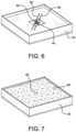
- FIG. 6is a perspective view of a precast insulated panel in a 6 th stage of construction.
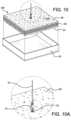
- FIG. 7is a perspective view of a precast insulated panel in a 7 th stage of construction.
- FIG. 8is a perspective view of a precast insulated panel in an 8th stage of construction.
- FIG. 8 Ais an enlargement of area 8 A in FIG. 8 .
- FIG. 9is a perspective view of a precast insulated panel in a 9 th stage of construction.
- FIG. 10is a cross-section of a precast insulated panel.
- FIG. 10 Ais an enlargement of area 10 A in FIG. 10 .
- FIG. 11is a perspective view of a first wythe engagement member the first mode of operation.
- FIG. 11 Ais a cross-section of the first wythe engagement member in the first mode of operation.
- FIG. 12is a perspective view of a first wythe engagement member in a 2 nd mode of operation.
- FIG. 12 Ais a cross-section of a first wythe engagement member in a 2 nd mode of operation.
- FIG. 13is a plan view of discontinuous fibers in a polymer matrix.
- FIG. 14is a plan view of woven fibers in a polymer matrix.
- a stripping lifting insertis provided for precast insulated panels having an insulating material layer between opposing wythes, the insulating material layer, wythes, and precast insulated panel having respective widths.
- the stripping lifting insertincludes an elongated connecting shaft having a shaft axis.
- First and second spaced apart wythe engagement membersare connected to the connecting shaft in spaced apart relation to each other.
- Each wythe engagement memberincludes a hub and a plurality of three or more protrusions connected to and emanating from the hub.
- the wythe engagement membershave a height less than the width of the wythes, whereby each wythe engagement member can be embedded in a respective wythe of the precast insulated panel.
- the position of the wythe engagement members on the shaftis adjustable.
- the hubs of the wythe engagement memberscan have a threaded interior opening, and an outside surface of the shaft is cooperatively threaded such that the wythes can be engaged to the threaded shaft, and the position of the wythe engagement members on the threaded shaft can be adjusted by threading the wythe engagement members along the length of the shaft.
- the interior threadcan be at least one selected from the group consisting of triangular or trapezoidal threads.
- the stripping lifting insertcan further include stripping lift engagement structure secured to an end of the shaft for engaging a stripping lifting device.
- the stripping lift engagement structurecan be any suitable structure.
- the stripping lift engagement structurecan be threaded and an end of the shaft can be cooperatively threaded to engage the stripping lift engagement structure.
- the plurality of protrusionscan have different numbers, sizes, thicknesses and widths, depending in part of the size and weight of the precast insulated panel.
- the plurality of protrusionscan comprise four equally spaced protrusions about the circumference of the hub.
- the four protrusionscan be arranged in a cross configuration.
- the stripping lifting insert of the inventioncan be made of different materials, but preferably are corrosion resistant and possess the strength to lift the precast panel from the mold or formwork.
- the wythe engagement memberscan be made from a fiber-reinforced polymer.
- the fiber-reinforced polymercan comprise discontinuous fibers in a polymer matrix.
- the fiber-reinforced polymercan also include, in the polymer matrix, continuous fibers and discontinuous fibers.
- the dimensions of the discontinuous fiberscan vary. In one embodiment, the lengths of the discontinuous fibers are in a range of 0.2′′ to 2′′.
- the fiber-reinforced polymercomprises fibers made from a suitable material.
- the fiberscan be at least one selected from the group consisting of glass fibers, carbon fibers, aramid fibers, basalt fibers, and combinations thereof. Other fiber materials are possible.
- the fibersare dispersed in a polymer matrix.
- the polymer matrixcan be a variety of different materials.
- the matrix materialcan be at least one selected from the group consisting of thermoplastic polyphenylene sulfide, polyethylene terephthalate, polyamide, polyurethane, polysulfone, polyether ketone, polyetherether ketone, thermoset epoxy, phenolic, vinyl ester and polyester. Other matrix materials are possible.
- the protrusionscan have varying sizes and shapes, but in general will have elongated portions which become embedded in and engage the wythes.
- the height of the hubis greater than the height of the protrusions, such that the hub can be flush with the surface of the wythe while protrusions remain embedded in the wythe, to facilitate connection of the shaft to the wythe engagement members.
- Each of the protrusionsextends radially outwardly from the shaft axis, and can be perpendicular or within any range of ⁇ 25 degrees of perpendicular to the shaft axis.
- Each protrusion of the plurality of protrusionscomprises respective ribs extending radially away from the hub.
- Each ribcan extend over 25% to 75% of the radial extension of the protrusion.
- Each ribcan extend 25%, 30%, 35%, 40%, 45%, 50%, 55%, 60%, 65%, 70%, or 75%, and can be within a range of any high value and low value selected from these values.
- the ribscan have a width of 20% to 60% of the width of the corresponding protrusion.
- the ribscan have a width of 20%, 25%, 30%, 35%, 40%, 45%, 50%, 55%, or 60% of the width of the corresponding protrusion, and can be within a range of any high value and low value selected from these values.
- the stripping lifting insertcan have different dimensions depending on the particular installation and particularly the dimensions and weight of the precast insulated panel for which it is intended. These panels can have very significant dimensions, for example 10-12 feet in height and 20-60 feet in length.
- a height of the stripping lifting insert along the shaft axisis in a range of 0.75′′ to 1.25′′.
- a radial extension of each protrusion of the plurality of protrusionscan be in a range of 2′′ to 8′′.
- a height of each protrusion of the plurality of protrusions along the shaft axiscan be in a range of from 1/16′′ to 1 ⁇ 4′′.
- a width of each protrusion of the plurality of protrusions orthogonal to a radial directioncan be in a range of from 0.5′′ to 1.5′′.
- a diameter of the connecting shaftcan be in a range of from 0.5′′ to 1.5′′. Other dimensions are possible.
- a precast insulated panelcan be provided in which one of the first and second wythe engagement members is embedded in a respective one of the first and second wythes of the precast insulated panel, and connected by the connecting shaft.
- the connecting shaftcan have secured thereto the lift engagement structure.
- a method of making a precast insulated panel having an insulating material layer between opposing wythescan include the step of providing a stripping lifting insert.
- the stripping lifting insertincludes an elongated connecting shaft having a shaft axis, and first and second spaced apart wythe engagement members connected to the shaft in spaced apart relation to each other.
- Each wythe engagement membercomprises a hub and a plurality of three or more protrusions connected to and distributed around the hub.
- Each of the protrusionsextends radially outward from the shaft axis, wherein the wythe engagement members have a height less than the width of the wythes, whereby each wythe engagement member can be embedded in a respective wythe of the precast insulated panel.
- the connecting shafthas a length greater than the width of the precast insulated panel such that a connecting end of the connecting shaft will protrude from one of the wythes.
- a mold or formwork for the precast insulated panelis provided. Concrete constituting a portion of a first wythe is placed into the mold. A first wythe engagement member is placed into the mold. A remainder of the concrete constituting the first wythe can then be poured, embedding the first wythe engagement member with the connecting shaft protruding. The protrusions are embedded within the concrete. The first wythe engagement member should have concrete underneath it. Other methods of construction are possible.
- An insulation material layeris then positioned over the wythe with the connecting shaft protruding from the insulation material layer.
- a second wythe engagement memberis attached to the connecting shaft. Concrete constituting a second wythe is poured over the insulation material layer, with the second wythe engagement member embedded within the second wythe, and the connecting shaft protruding from the second wythe, to form a precast insulated panel. Stripping lifting engagement structure can be connected to the elongated connecting shaft protruding from the second wythe, and the precast insulated panel can be lifted from the mold by a suitable lifting device such as a crane.
- FIGS. 1 - 14There is shown in FIGS. 1 - 14 a precast insulated panel assembly system 10 and method in which a stripping lifting insert according to the invention is positioned in a mold 18 used to make the precast insulated panel.
- a first wythe engagement member 14can be positioned in the mold on an initial concrete portion of a first wythe 24 and optionally rebar 22 can be included.
- the first wythe engagement member 14is comprised by a hub 26 and a plurality of radially extending protrusions 30 .
- a connecting shaft 40can be secured to the hub 26 by suitable structures such as cooperating threads.
- a remaining portion of concrete wythe 24is then poured so as to embed the first wythe engagement member 14 , leaving a portion of the connecting shaft 40 extending from the first wythe 24 ( FIG. 3 ).
- An insulation layer 50is then positioned in the mold 18 onto the first wythe 24 ( FIG. 4 ).
- the insulation layer 50can have a cut out portion 52 .
- a second wythe engagement member 44can then be threaded onto the connecting shaft 40 and placed on the first wythe 24 within the cut out portion 52 ( FIG. 5 ).
- rebar 56 and 58which can be fiber-reinforced polymer can be positioned over the second wythe engagement member 44 to provide additional engagement to a second wythe and added strength during the stripping lifting procedure ( FIG. 6 ).
- a second concrete wythe 60can then be poured ( FIG. 7 ). The end portion of the connecting shaft 40 will extend out of the second concrete wythe 60 .
- Stripping lift engagement structure 66can be secured to the end portion of the connecting shaft 40 extending from the second concrete wythe 60 .
- the stripping lifting engagement structure 66can take many forms, but in the embodiment shown in FIG. 8 A includes a base 67 , a connecting nut 68 for engaging the connecting shaft 40 , and a U-shaped portion for connecting to a stripping lifting device.
- the first wythe engagement member 14is embedded in the first wythe 24
- the second wythe engagement member 44is embedded in the second wythe 60 .
- the stripping lifting deviceapplies a lifting force to the stripping lifting engagement structure 66
- the first wythe 24 and second wythe 60will be simultaneously acted upon by the respective first wythe engagement member 14 and second wythe engagement member 44 through the connecting shaft 40 .
- Rebar 56 and 58will provide additional strength.
- the stripping lifting devicesuch as a crane is used to lift the completed precast insulated panel 100 from the mold 18 .
- the craneincludes a lifting cable 72 and hook 70 used to engage the U-shaped portion 70 of the stripping lifting engagement structure 66 .
- the inventioncan be used with other kinds of stripping lifting devices.
- the wythe engagement memberssuch as the first wythe engagement member 14 can have additional structure for strengthening these members.
- Such structurecan be radially extending ribs 84 on the protrusions 30 .
- the manner of connecting the connecting shaft 42 the wythe engagement memberscan vary but in the embodiment shown the connecting shaft 40 has threads 42 which engage cooperating threads 82 in a threaded opening 80 in the hub 26 . In this manner, each wythe engagement member can be axially adjustable on the connecting shaft 40 by rotation of the wythe engagement member on the connecting shaft 40 .
- the wythe engagement membersare preferably made of a strong, lightweight and corrosion resistant material. Such materials include fiber reinforced polymer. As shown in FIG. 13 , discontinuous fibers 90 can be provided in a polymer matrix 92 . As shown in FIG. 14 , woven fibers 94 can be provided in a polymer matrix 96 . Other continuous and discontinuous fiber reinforced polymer structures are possible.
Landscapes
- Engineering & Computer Science (AREA)
- Architecture (AREA)
- Mechanical Engineering (AREA)
- Civil Engineering (AREA)
- Structural Engineering (AREA)
- Chemical & Material Sciences (AREA)
- Ceramic Engineering (AREA)
- Manufacturing & Machinery (AREA)
- Laminated Bodies (AREA)
Abstract
Description
Claims (31)
Priority Applications (1)
| Application Number | Priority Date | Filing Date | Title |
|---|---|---|---|
| US17/187,044US11661741B2 (en) | 2020-02-26 | 2021-02-26 | Non-corroding stripping lifting inserts for precast insulated panels |
Applications Claiming Priority (2)
| Application Number | Priority Date | Filing Date | Title |
|---|---|---|---|
| US202062981677P | 2020-02-26 | 2020-02-26 | |
| US17/187,044US11661741B2 (en) | 2020-02-26 | 2021-02-26 | Non-corroding stripping lifting inserts for precast insulated panels |
Publications (2)
| Publication Number | Publication Date |
|---|---|
| US20210262227A1 US20210262227A1 (en) | 2021-08-26 |
| US11661741B2true US11661741B2 (en) | 2023-05-30 |
Family
ID=77365902
Family Applications (1)
| Application Number | Title | Priority Date | Filing Date |
|---|---|---|---|
| US17/187,044Active2042-01-23US11661741B2 (en) | 2020-02-26 | 2021-02-26 | Non-corroding stripping lifting inserts for precast insulated panels |
Country Status (1)
| Country | Link |
|---|---|
| US (1) | US11661741B2 (en) |
Cited By (1)
| Publication number | Priority date | Publication date | Assignee | Title |
|---|---|---|---|---|
| US11976460B1 (en)* | 2019-12-05 | 2024-05-07 | James E. Schneider | Security anchor and method |
Families Citing this family (3)
| Publication number | Priority date | Publication date | Assignee | Title |
|---|---|---|---|---|
| US20210262217A1 (en)* | 2020-02-26 | 2021-08-26 | Ut-Battelle, Llc | Non-corroding erection lifting inserts for precast insulated panels |
| EP4225635A1 (en)* | 2020-10-05 | 2023-08-16 | RRD Engineering, LLC dba the Floating Wind Technology Company | Concrete suction anchor |
| TWI823797B (en)* | 2023-03-13 | 2023-11-21 | 潤弘精密工程事業股份有限公司 | Precast base, method of manufacturing the precast base and method of mounting architectural structure having the precast base |
Citations (33)
| Publication number | Priority date | Publication date | Assignee | Title |
|---|---|---|---|---|
| US3115726A (en)* | 1962-02-16 | 1963-12-31 | Louis F Sayles Sr | Stabilizer plate for screed chairs |
| US3420014A (en)* | 1967-10-05 | 1969-01-07 | Superior Concrete Accessories | Anchor insert and pick-up unit therefor |
| US3431012A (en)* | 1967-10-23 | 1969-03-04 | Superior Concrete Accessories | Anchor insert and pickup unit for a concrete slab |
| FR1563919A (en)* | 1968-02-19 | 1969-04-18 | ||
| GB1250008A (en)* | 1968-06-05 | 1971-10-20 | Rawlplug Co Ltd | Improvements in the casting of concrete articles |
| GB1356987A (en)* | 1970-07-09 | 1974-06-19 | Eich A | Pre-fabricated wall elements |
| US4000591A (en)* | 1975-08-04 | 1977-01-04 | Superior Concrete Accessories, Inc. | Holder adapted for supporting an anchor insert to be embedded in a concrete slab |
| US4017115A (en)* | 1975-12-17 | 1977-04-12 | The Burke Company | Lift system for concrete slabs |
| US4074499A (en)* | 1976-01-12 | 1978-02-21 | The Dayton Sure-Grip & Shore Company | Filler plug for coil insert in concrete slab or panel |
| DE2802121A1 (en)* | 1977-01-21 | 1978-07-27 | Dayton Sure Grip & Shore Co | FILLING PLUG FOR A SPOOL INSERT IN A CONCRETE PANEL OR SLAB |
| US4204711A (en)* | 1978-07-20 | 1980-05-27 | Brown Company | Coupling for lift system for concrete slabs |
| FR2491529A1 (en)* | 1980-10-02 | 1982-04-09 | Goldberg Juergen | DEVICE FOR FORMING A RECESS IN PREFABRICATED CONCRETE ELEMENTS |
| FR2543481A1 (en)* | 1983-03-31 | 1984-10-05 | Francis Laroche | Device for anchoring in concrete |
| US4580378A (en)* | 1984-03-26 | 1986-04-08 | The Burke Company | Anchor assembly for tilt-up wall section |
| FR2574697A2 (en)* | 1983-03-31 | 1986-06-20 | Laroche Francis | Anchoring device |
| US4660344A (en)* | 1983-11-02 | 1987-04-28 | Gaudelli Edmond N | Apparatus and procedure for forming pre-shaped interlocking cement slabs |
| US5014473A (en)* | 1989-03-22 | 1991-05-14 | The Burke Company | Apparatus and method for lifting tilt-up wall constructions |
| US5058348A (en)* | 1987-06-01 | 1991-10-22 | Pell Sune Westhed | Method and apparatus for forming a path for a screeding means |
| US6341452B1 (en)* | 1999-10-21 | 2002-01-29 | Gebr. Seifert Gmbh & Co. | Transport anchor for embedding in prefabricated reinforced concrete parts |
| WO2004001147A2 (en)* | 2002-06-21 | 2003-12-31 | Composite Technologies Corporation | Post-tensioned insulated wall panels |
| AU2009100142A4 (en)* | 2009-02-13 | 2009-03-19 | Illinois Tool Works Inc. | Cast-in ferrule |
| FR2926576A1 (en)* | 2008-01-18 | 2009-07-24 | Kp1 Soc Par Actions Simplifiee | Guiderail stud step device, has ballast housed in central cylindrical barrel whose weight is related to buoyancy of device in liquid concrete bath, where barrel is limited at one end by closed base and at another rend by opening |
| US20100037536A1 (en)* | 2008-08-12 | 2010-02-18 | Schulze Todd M | Concrete panel lifting insert assembly |
| WO2012129177A1 (en)* | 2011-03-18 | 2012-09-27 | Espinosa Thomas M | Concrete anchor coupling assembly and anchor rod holder |
| FR2978468A1 (en)* | 2011-07-28 | 2013-02-01 | Rech Et D Industrialisation Du Batiment Soc D | Connection and lifting assistance system for wall panel, has thimble fixed to body of anchor while extending from one face to another face of anchor so as to allow cable to pass under anchor and on both sides of anchor |
| US8875471B2 (en)* | 2012-08-24 | 2014-11-04 | Baltazar Siqueiros | Method and apparatus for lifting and leveling a concrete panel |
| US20150284967A1 (en)* | 2014-04-03 | 2015-10-08 | Hong Nam KIM | Multiple cast-in insert apparatus for concrete |
| US20160244986A1 (en)* | 2015-02-20 | 2016-08-25 | Stephen Atkinson | Bricklaying |
| US20180023296A1 (en)* | 2016-07-21 | 2018-01-25 | Meadow Burke, Llc | Lifting and leveling insert for a precast concrete slab |
| KR20180078615A (en)* | 2016-12-30 | 2018-07-10 | 주식회사 구들택 | High Strength Concrete nuts and manufacturing methods |
| EP3736389A1 (en)* | 2019-05-07 | 2020-11-11 | Thermacrete, LLC | Autoclave aerated concrete structures with embedded hangers and connectors |
| FR3112566A1 (en)* | 2020-07-16 | 2022-01-21 | Josselin Guicherd | Lifting device for lifting a double wall. |
| US11421431B1 (en)* | 2019-02-21 | 2022-08-23 | ALP Supply, Inc. | Erection anchor with coil legs |
- 2021
- 2021-02-26USUS17/187,044patent/US11661741B2/enactiveActive
Patent Citations (33)
| Publication number | Priority date | Publication date | Assignee | Title |
|---|---|---|---|---|
| US3115726A (en)* | 1962-02-16 | 1963-12-31 | Louis F Sayles Sr | Stabilizer plate for screed chairs |
| US3420014A (en)* | 1967-10-05 | 1969-01-07 | Superior Concrete Accessories | Anchor insert and pick-up unit therefor |
| US3431012A (en)* | 1967-10-23 | 1969-03-04 | Superior Concrete Accessories | Anchor insert and pickup unit for a concrete slab |
| FR1563919A (en)* | 1968-02-19 | 1969-04-18 | ||
| GB1250008A (en)* | 1968-06-05 | 1971-10-20 | Rawlplug Co Ltd | Improvements in the casting of concrete articles |
| GB1356987A (en)* | 1970-07-09 | 1974-06-19 | Eich A | Pre-fabricated wall elements |
| US4000591A (en)* | 1975-08-04 | 1977-01-04 | Superior Concrete Accessories, Inc. | Holder adapted for supporting an anchor insert to be embedded in a concrete slab |
| US4017115A (en)* | 1975-12-17 | 1977-04-12 | The Burke Company | Lift system for concrete slabs |
| US4074499A (en)* | 1976-01-12 | 1978-02-21 | The Dayton Sure-Grip & Shore Company | Filler plug for coil insert in concrete slab or panel |
| DE2802121A1 (en)* | 1977-01-21 | 1978-07-27 | Dayton Sure Grip & Shore Co | FILLING PLUG FOR A SPOOL INSERT IN A CONCRETE PANEL OR SLAB |
| US4204711A (en)* | 1978-07-20 | 1980-05-27 | Brown Company | Coupling for lift system for concrete slabs |
| FR2491529A1 (en)* | 1980-10-02 | 1982-04-09 | Goldberg Juergen | DEVICE FOR FORMING A RECESS IN PREFABRICATED CONCRETE ELEMENTS |
| FR2543481A1 (en)* | 1983-03-31 | 1984-10-05 | Francis Laroche | Device for anchoring in concrete |
| FR2574697A2 (en)* | 1983-03-31 | 1986-06-20 | Laroche Francis | Anchoring device |
| US4660344A (en)* | 1983-11-02 | 1987-04-28 | Gaudelli Edmond N | Apparatus and procedure for forming pre-shaped interlocking cement slabs |
| US4580378A (en)* | 1984-03-26 | 1986-04-08 | The Burke Company | Anchor assembly for tilt-up wall section |
| US5058348A (en)* | 1987-06-01 | 1991-10-22 | Pell Sune Westhed | Method and apparatus for forming a path for a screeding means |
| US5014473A (en)* | 1989-03-22 | 1991-05-14 | The Burke Company | Apparatus and method for lifting tilt-up wall constructions |
| US6341452B1 (en)* | 1999-10-21 | 2002-01-29 | Gebr. Seifert Gmbh & Co. | Transport anchor for embedding in prefabricated reinforced concrete parts |
| WO2004001147A2 (en)* | 2002-06-21 | 2003-12-31 | Composite Technologies Corporation | Post-tensioned insulated wall panels |
| FR2926576A1 (en)* | 2008-01-18 | 2009-07-24 | Kp1 Soc Par Actions Simplifiee | Guiderail stud step device, has ballast housed in central cylindrical barrel whose weight is related to buoyancy of device in liquid concrete bath, where barrel is limited at one end by closed base and at another rend by opening |
| US20100037536A1 (en)* | 2008-08-12 | 2010-02-18 | Schulze Todd M | Concrete panel lifting insert assembly |
| AU2009100142A4 (en)* | 2009-02-13 | 2009-03-19 | Illinois Tool Works Inc. | Cast-in ferrule |
| WO2012129177A1 (en)* | 2011-03-18 | 2012-09-27 | Espinosa Thomas M | Concrete anchor coupling assembly and anchor rod holder |
| FR2978468A1 (en)* | 2011-07-28 | 2013-02-01 | Rech Et D Industrialisation Du Batiment Soc D | Connection and lifting assistance system for wall panel, has thimble fixed to body of anchor while extending from one face to another face of anchor so as to allow cable to pass under anchor and on both sides of anchor |
| US8875471B2 (en)* | 2012-08-24 | 2014-11-04 | Baltazar Siqueiros | Method and apparatus for lifting and leveling a concrete panel |
| US20150284967A1 (en)* | 2014-04-03 | 2015-10-08 | Hong Nam KIM | Multiple cast-in insert apparatus for concrete |
| US20160244986A1 (en)* | 2015-02-20 | 2016-08-25 | Stephen Atkinson | Bricklaying |
| US20180023296A1 (en)* | 2016-07-21 | 2018-01-25 | Meadow Burke, Llc | Lifting and leveling insert for a precast concrete slab |
| KR20180078615A (en)* | 2016-12-30 | 2018-07-10 | 주식회사 구들택 | High Strength Concrete nuts and manufacturing methods |
| US11421431B1 (en)* | 2019-02-21 | 2022-08-23 | ALP Supply, Inc. | Erection anchor with coil legs |
| EP3736389A1 (en)* | 2019-05-07 | 2020-11-11 | Thermacrete, LLC | Autoclave aerated concrete structures with embedded hangers and connectors |
| FR3112566A1 (en)* | 2020-07-16 | 2022-01-21 | Josselin Guicherd | Lifting device for lifting a double wall. |
Cited By (1)
| Publication number | Priority date | Publication date | Assignee | Title |
|---|---|---|---|---|
| US11976460B1 (en)* | 2019-12-05 | 2024-05-07 | James E. Schneider | Security anchor and method |
Also Published As
| Publication number | Publication date |
|---|---|
| US20210262227A1 (en) | 2021-08-26 |
Similar Documents
| Publication | Publication Date | Title |
|---|---|---|
| US11661741B2 (en) | Non-corroding stripping lifting inserts for precast insulated panels | |
| US10309105B2 (en) | System for insulated concrete composite wall panels | |
| JP2011052692A (en) | Wind turbine tower; system and method for manufacturing the same | |
| US9512593B2 (en) | Anti-torsion anchor bolt | |
| JPS5858052B2 (en) | artificial reef | |
| KR102311242B1 (en) | Utility pole | |
| US20170191268A1 (en) | Pre-Stressed Concrete Body | |
| JP6538091B2 (en) | Cable fixing means for horizontal joint and cable fixing procedure for horizontal joint | |
| WO2019246259A1 (en) | Device and method for forming voids in concrete | |
| CN110485796A (en) | An integrated insulating cross arm | |
| US20210262217A1 (en) | Non-corroding erection lifting inserts for precast insulated panels | |
| CN111287901B (en) | Lower tower section of concrete tower and concrete tower having the same | |
| CN112886481B (en) | Cable laying method for inner climbing type tower crane | |
| US20250092669A1 (en) | Attachment device for a roof nailer pane. | |
| KR102647104B1 (en) | Lifting device for large scale asphalt mat | |
| US20240291248A1 (en) | Utility pole | |
| US20180022571A1 (en) | Reinforced cable spool | |
| CN111287900B (en) | Upper tower section of concrete tower and concrete tower having the same | |
| KR101920025B1 (en) | Attachment device for handling of paper formwork | |
| US9821496B2 (en) | Method of forming one or more flanges on or in a hollow continuously wound structural member | |
| JP6051073B2 (en) | Anchor, manufacturing method thereof, fixing tool, method of reinforcing structure using the same, and reinforced structure | |
| KR20180137863A (en) | Position Setting Bolt for Pile Lifting Device Installation and Pile Lifting Method | |
| WO2019111170A1 (en) | A concrete starter bar retention and locating device, systems and methods comprising the same |
Legal Events
| Date | Code | Title | Description |
|---|---|---|---|
| FEPP | Fee payment procedure | Free format text:ENTITY STATUS SET TO UNDISCOUNTED (ORIGINAL EVENT CODE: BIG.); ENTITY STATUS OF PATENT OWNER: SMALL ENTITY | |
| FEPP | Fee payment procedure | Free format text:ENTITY STATUS SET TO SMALL (ORIGINAL EVENT CODE: SMAL); ENTITY STATUS OF PATENT OWNER: SMALL ENTITY | |
| STPP | Information on status: patent application and granting procedure in general | Free format text:DOCKETED NEW CASE - READY FOR EXAMINATION | |
| AS | Assignment | Owner name:U. S. DEPARTMENT OF ENERGY, DISTRICT OF COLUMBIA Free format text:CONFIRMATORY LICENSE;ASSIGNOR:UT-BATTELLE, LLC;REEL/FRAME:058387/0112 Effective date:20210518 | |
| AS | Assignment | Owner name:OAK RIDGE ASSOCIATED UNIVERSITIES, TENNESSEE Free format text:ASSIGNMENT OF ASSIGNORS INTEREST;ASSIGNOR:TALLEY, DYLAN M.;REEL/FRAME:061147/0061 Effective date:20220502 Owner name:UT-BATTELLE, LLC, TENNESSEE Free format text:ASSIGNMENT OF ASSIGNORS INTEREST;ASSIGNORS:HUN, DIANA;HAYES, NOLAN W.;SIGNING DATES FROM 20220426 TO 20220620;REEL/FRAME:061146/0758 | |
| AS | Assignment | Owner name:UNIVERSITY OF TENNESSEE RESEARCH FOUNDATION, TENNESSEE Free format text:ASSIGNMENT OF ASSIGNORS INTEREST;ASSIGNORS:SHERIFF, STEPHEN W.;MA, ZHONGGUO JOHN;SIGNING DATES FROM 20220531 TO 20220620;REEL/FRAME:063321/0688 | |
| STCF | Information on status: patent grant | Free format text:PATENTED CASE |