US11660201B2 - Systems, apparatuses, and methods for correcting a bone defect - Google Patents
Systems, apparatuses, and methods for correcting a bone defectDownload PDFInfo
- Publication number
- US11660201B2 US11660201B2US16/170,250US201816170250AUS11660201B2US 11660201 B2US11660201 B2US 11660201B2US 201816170250 AUS201816170250 AUS 201816170250AUS 11660201 B2US11660201 B2US 11660201B2
- Authority
- US
- United States
- Prior art keywords
- implant
- inserter
- intramedullary
- extramedullary
- longitudinal axis
- Prior art date
- Legal status (The legal status is an assumption and is not a legal conclusion. Google has not performed a legal analysis and makes no representation as to the accuracy of the status listed.)
- Active, expires
Links
- 210000000988bone and boneAnatomy0.000titleclaimsabstractdescription92
- 238000000034methodMethods0.000titledescription18
- 230000007547defectEffects0.000title1
- 239000007943implantSubstances0.000claimsabstractdescription117
- 230000008878couplingEffects0.000claimsabstractdescription9
- 238000010168coupling processMethods0.000claimsabstractdescription9
- 238000005859coupling reactionMethods0.000claimsabstractdescription9
- 210000001872metatarsal boneAnatomy0.000claimsdescription22
- 230000003116impacting effectEffects0.000claimsdescription9
- 239000012634fragmentSubstances0.000description34
- 238000003780insertionMethods0.000description10
- 230000037431insertionEffects0.000description10
- 229910052751metalInorganic materials0.000description7
- 239000002184metalSubstances0.000description7
- 239000011248coating agentSubstances0.000description6
- 238000000576coating methodMethods0.000description6
- 208000025740Tailor BunionDiseases0.000description5
- 239000012620biological materialSubstances0.000description5
- 238000005553drillingMethods0.000description5
- 239000000463materialSubstances0.000description5
- 239000000758substrateSubstances0.000description5
- 238000005516engineering processMethods0.000description4
- 239000000203mixtureSubstances0.000description4
- 230000003014reinforcing effectEffects0.000description4
- 102000007350Bone Morphogenetic ProteinsHuman genes0.000description3
- 108010007726Bone Morphogenetic ProteinsProteins0.000description3
- 239000002131composite materialSubstances0.000description3
- 210000002683footAnatomy0.000description3
- 229910052588hydroxylapatiteInorganic materials0.000description3
- 238000001746injection mouldingMethods0.000description3
- 239000012778molding materialSubstances0.000description3
- XYJRXVWERLGGKC-UHFFFAOYSA-Dpentacalcium;hydroxide;triphosphateChemical compound[OH-].[Ca+2].[Ca+2].[Ca+2].[Ca+2].[Ca+2].[O-]P([O-])([O-])=O.[O-]P([O-])([O-])=O.[O-]P([O-])([O-])=OXYJRXVWERLGGKC-UHFFFAOYSA-D0.000description3
- 229920000747poly(lactic acid)Polymers0.000description3
- 239000007921spraySubstances0.000description3
- RTAQQCXQSZGOHL-UHFFFAOYSA-NTitaniumChemical compound[Ti]RTAQQCXQSZGOHL-UHFFFAOYSA-N0.000description2
- 241001227561ValgusSpecies0.000description2
- 239000011324beadSubstances0.000description2
- 210000001185bone marrowAnatomy0.000description2
- 229940112869bone morphogenetic proteinDrugs0.000description2
- 230000001788irregularEffects0.000description2
- -1neodymium or cerium)Chemical compound0.000description2
- 239000004417polycarbonateSubstances0.000description2
- 229920000515polycarbonatePolymers0.000description2
- 239000004626polylactic acidSubstances0.000description2
- 229920000642polymerPolymers0.000description2
- 239000010936titaniumSubstances0.000description2
- 229910052719titaniumInorganic materials0.000description2
- QORWJWZARLRLPR-UHFFFAOYSA-Htricalcium bis(phosphate)Chemical compound[Ca+2].[Ca+2].[Ca+2].[O-]P([O-])([O-])=O.[O-]P([O-])([O-])=OQORWJWZARLRLPR-UHFFFAOYSA-H0.000description2
- 238000007514turningMethods0.000description2
- 108010081589BecaplerminProteins0.000description1
- 206010070918Bone deformityDiseases0.000description1
- 229910052684CeriumInorganic materials0.000description1
- 229910000684Cobalt-chromeInorganic materials0.000description1
- 206010061159Foot deformityDiseases0.000description1
- AEMRFAOFKBGASW-UHFFFAOYSA-NGlycolic acidPolymersOCC(O)=OAEMRFAOFKBGASW-UHFFFAOYSA-N0.000description1
- 206010061218InflammationDiseases0.000description1
- 206010023204Joint dislocationDiseases0.000description1
- WHXSMMKQMYFTQS-UHFFFAOYSA-NLithiumChemical compound[Li]WHXSMMKQMYFTQS-UHFFFAOYSA-N0.000description1
- 229910000861Mg alloyInorganic materials0.000description1
- 229910052779NeodymiumInorganic materials0.000description1
- 239000004677NylonSubstances0.000description1
- 208000006735PeriostitisDiseases0.000description1
- 239000004952PolyamideSubstances0.000description1
- 229920002732PolyanhydridePolymers0.000description1
- 229920000954PolyglycolidePolymers0.000description1
- 229920000331PolyhydroxybutyratePolymers0.000description1
- 229920001710PolyorthoesterPolymers0.000description1
- 208000027418Wounds and injuryDiseases0.000description1
- HCHKCACWOHOZIP-UHFFFAOYSA-NZincChemical compound[Zn]HCHKCACWOHOZIP-UHFFFAOYSA-N0.000description1
- 239000004676acrylonitrile butadiene styreneSubstances0.000description1
- 229910052782aluminiumInorganic materials0.000description1
- XAGFODPZIPBFFR-UHFFFAOYSA-NaluminiumChemical compound[Al]XAGFODPZIPBFFR-UHFFFAOYSA-N0.000description1
- 230000000845anti-microbial effectEffects0.000description1
- 239000004599antimicrobialSubstances0.000description1
- 238000005452bendingMethods0.000description1
- 239000005313bioactive glassSubstances0.000description1
- 230000003115biocidal effectEffects0.000description1
- 230000015572biosynthetic processEffects0.000description1
- 210000002805bone matrixAnatomy0.000description1
- GWXLDORMOJMVQZ-UHFFFAOYSA-NceriumChemical compound[Ce]GWXLDORMOJMVQZ-UHFFFAOYSA-N0.000description1
- 239000010952cobalt-chromeSubstances0.000description1
- 239000012141concentrateSubstances0.000description1
- 229920001577copolymerPolymers0.000description1
- 238000010586diagramMethods0.000description1
- 230000000694effectsEffects0.000description1
- 210000003871fifth metatarsal boneAnatomy0.000description1
- 238000009472formulationMethods0.000description1
- 239000008187granular materialSubstances0.000description1
- 238000000227grindingMethods0.000description1
- 239000003102growth factorSubstances0.000description1
- 230000004054inflammatory processEffects0.000description1
- 229910052744lithiumInorganic materials0.000description1
- WPBNNNQJVZRUHP-UHFFFAOYSA-Lmanganese(2+);methyl n-[[2-(methoxycarbonylcarbamothioylamino)phenyl]carbamothioyl]carbamate;n-[2-(sulfidocarbothioylamino)ethyl]carbamodithioateChemical compound[Mn+2].[S-]C(=S)NCCNC([S-])=S.COC(=O)NC(=S)NC1=CC=CC=C1NC(=S)NC(=O)OCWPBNNNQJVZRUHP-UHFFFAOYSA-L0.000description1
- 230000013011matingEffects0.000description1
- 239000007769metal materialSubstances0.000description1
- 150000002739metalsChemical class0.000description1
- 210000003789metatarsusAnatomy0.000description1
- 238000003801millingMethods0.000description1
- QEFYFXOXNSNQGX-UHFFFAOYSA-Nneodymium atomChemical compound[Nd]QEFYFXOXNSNQGX-UHFFFAOYSA-N0.000description1
- 229920001778nylonPolymers0.000description1
- 230000000278osteoconductive effectEffects0.000description1
- 230000002138osteoinductive effectEffects0.000description1
- 238000004806packaging method and processMethods0.000description1
- 239000002245particleSubstances0.000description1
- 210000003460periosteumAnatomy0.000description1
- 239000004033plasticSubstances0.000description1
- 229920003023plasticPolymers0.000description1
- 239000005015poly(hydroxybutyrate)Substances0.000description1
- 229920002647polyamidePolymers0.000description1
- 229920001610polycaprolactonePolymers0.000description1
- 239000004632polycaprolactoneSubstances0.000description1
- 239000002861polymer materialSubstances0.000description1
- 229920002635polyurethanePolymers0.000description1
- 239000004814polyurethaneSubstances0.000description1
- 239000000843powderSubstances0.000description1
- 238000002360preparation methodMethods0.000description1
- 230000001737promoting effectEffects0.000description1
- 108090000623proteins and genesProteins0.000description1
- 102000004169proteins and genesHuman genes0.000description1
- 229910052761rare earth metalInorganic materials0.000description1
- 150000002910rare earth metalsChemical class0.000description1
- 238000010079rubber tappingMethods0.000description1
- 239000000243solutionSubstances0.000description1
- 239000010935stainless steelSubstances0.000description1
- 229910001220stainless steelInorganic materials0.000description1
- 229910052712strontiumInorganic materials0.000description1
- CIOAGBVUUVVLOB-UHFFFAOYSA-Nstrontium atomChemical compound[Sr]CIOAGBVUUVVLOB-UHFFFAOYSA-N0.000description1
- 238000001356surgical procedureMethods0.000description1
- 230000007704transitionEffects0.000description1
- 239000011701zincSubstances0.000description1
- 229910052725zincInorganic materials0.000description1
Images


Classifications
- A—HUMAN NECESSITIES
- A61—MEDICAL OR VETERINARY SCIENCE; HYGIENE
- A61F—FILTERS IMPLANTABLE INTO BLOOD VESSELS; PROSTHESES; DEVICES PROVIDING PATENCY TO, OR PREVENTING COLLAPSING OF, TUBULAR STRUCTURES OF THE BODY, e.g. STENTS; ORTHOPAEDIC, NURSING OR CONTRACEPTIVE DEVICES; FOMENTATION; TREATMENT OR PROTECTION OF EYES OR EARS; BANDAGES, DRESSINGS OR ABSORBENT PADS; FIRST-AID KITS
- A61F2/00—Filters implantable into blood vessels; Prostheses, i.e. artificial substitutes or replacements for parts of the body; Appliances for connecting them with the body; Devices providing patency to, or preventing collapsing of, tubular structures of the body, e.g. stents
- A61F2/02—Prostheses implantable into the body
- A61F2/30—Joints
- A61F2/42—Joints for wrists or ankles; for hands, e.g. fingers; for feet, e.g. toes
- A61F2/4225—Joints for wrists or ankles; for hands, e.g. fingers; for feet, e.g. toes for feet, e.g. toes
- A—HUMAN NECESSITIES
- A61—MEDICAL OR VETERINARY SCIENCE; HYGIENE
- A61B—DIAGNOSIS; SURGERY; IDENTIFICATION
- A61B17/00—Surgical instruments, devices or methods
- A61B17/16—Instruments for performing osteoclasis; Drills or chisels for bones; Trepans
- A61B17/1662—Instruments for performing osteoclasis; Drills or chisels for bones; Trepans for particular parts of the body
- A61B17/1682—Instruments for performing osteoclasis; Drills or chisels for bones; Trepans for particular parts of the body for the foot or ankle
- A—HUMAN NECESSITIES
- A61—MEDICAL OR VETERINARY SCIENCE; HYGIENE
- A61B—DIAGNOSIS; SURGERY; IDENTIFICATION
- A61B17/00—Surgical instruments, devices or methods
- A61B17/16—Instruments for performing osteoclasis; Drills or chisels for bones; Trepans
- A61B17/17—Guides or aligning means for drills, mills, pins or wires
- A61B17/1739—Guides or aligning means for drills, mills, pins or wires specially adapted for particular parts of the body
- A61B17/1775—Guides or aligning means for drills, mills, pins or wires specially adapted for particular parts of the body for the foot or ankle
- A—HUMAN NECESSITIES
- A61—MEDICAL OR VETERINARY SCIENCE; HYGIENE
- A61B—DIAGNOSIS; SURGERY; IDENTIFICATION
- A61B17/00—Surgical instruments, devices or methods
- A61B17/56—Surgical instruments or methods for treatment of bones or joints; Devices specially adapted therefor
- A61B17/58—Surgical instruments or methods for treatment of bones or joints; Devices specially adapted therefor for osteosynthesis, e.g. bone plates, screws or setting implements
- A61B17/68—Internal fixation devices, including fasteners and spinal fixators, even if a part thereof projects from the skin
- A61B17/72—Intramedullary devices, e.g. pins or nails
- A61B17/7291—Intramedullary devices, e.g. pins or nails for small bones, e.g. in the foot, ankle, hand or wrist
- A—HUMAN NECESSITIES
- A61—MEDICAL OR VETERINARY SCIENCE; HYGIENE
- A61B—DIAGNOSIS; SURGERY; IDENTIFICATION
- A61B17/00—Surgical instruments, devices or methods
- A61B17/56—Surgical instruments or methods for treatment of bones or joints; Devices specially adapted therefor
- A61B17/58—Surgical instruments or methods for treatment of bones or joints; Devices specially adapted therefor for osteosynthesis, e.g. bone plates, screws or setting implements
- A61B17/88—Osteosynthesis instruments; Methods or means for implanting or extracting internal or external fixation devices
- A61B17/90—Guides therefor
- A—HUMAN NECESSITIES
- A61—MEDICAL OR VETERINARY SCIENCE; HYGIENE
- A61B—DIAGNOSIS; SURGERY; IDENTIFICATION
- A61B17/00—Surgical instruments, devices or methods
- A61B17/56—Surgical instruments or methods for treatment of bones or joints; Devices specially adapted therefor
- A61B17/58—Surgical instruments or methods for treatment of bones or joints; Devices specially adapted therefor for osteosynthesis, e.g. bone plates, screws or setting implements
- A61B17/88—Osteosynthesis instruments; Methods or means for implanting or extracting internal or external fixation devices
- A61B17/92—Impactors or extractors, e.g. for removing intramedullary devices
- A61B17/921—Impactors or extractors, e.g. for removing intramedullary devices for intramedullary devices
- A—HUMAN NECESSITIES
- A61—MEDICAL OR VETERINARY SCIENCE; HYGIENE
- A61F—FILTERS IMPLANTABLE INTO BLOOD VESSELS; PROSTHESES; DEVICES PROVIDING PATENCY TO, OR PREVENTING COLLAPSING OF, TUBULAR STRUCTURES OF THE BODY, e.g. STENTS; ORTHOPAEDIC, NURSING OR CONTRACEPTIVE DEVICES; FOMENTATION; TREATMENT OR PROTECTION OF EYES OR EARS; BANDAGES, DRESSINGS OR ABSORBENT PADS; FIRST-AID KITS
- A61F2/00—Filters implantable into blood vessels; Prostheses, i.e. artificial substitutes or replacements for parts of the body; Appliances for connecting them with the body; Devices providing patency to, or preventing collapsing of, tubular structures of the body, e.g. stents
- A61F2/02—Prostheses implantable into the body
- A61F2/30—Joints
- A61F2/46—Special tools for implanting artificial joints
- A61F2/4603—Special tools for implanting artificial joints for insertion or extraction of endoprosthetic joints or of accessories thereof
- A61F2/4606—Special tools for implanting artificial joints for insertion or extraction of endoprosthetic joints or of accessories thereof of wrists or ankles; of hands, e.g. fingers; of feet, e.g. toes
- A—HUMAN NECESSITIES
- A61—MEDICAL OR VETERINARY SCIENCE; HYGIENE
- A61F—FILTERS IMPLANTABLE INTO BLOOD VESSELS; PROSTHESES; DEVICES PROVIDING PATENCY TO, OR PREVENTING COLLAPSING OF, TUBULAR STRUCTURES OF THE BODY, e.g. STENTS; ORTHOPAEDIC, NURSING OR CONTRACEPTIVE DEVICES; FOMENTATION; TREATMENT OR PROTECTION OF EYES OR EARS; BANDAGES, DRESSINGS OR ABSORBENT PADS; FIRST-AID KITS
- A61F2/00—Filters implantable into blood vessels; Prostheses, i.e. artificial substitutes or replacements for parts of the body; Appliances for connecting them with the body; Devices providing patency to, or preventing collapsing of, tubular structures of the body, e.g. stents
- A61F2/02—Prostheses implantable into the body
- A61F2/30—Joints
- A61F2/42—Joints for wrists or ankles; for hands, e.g. fingers; for feet, e.g. toes
- A61F2/4225—Joints for wrists or ankles; for hands, e.g. fingers; for feet, e.g. toes for feet, e.g. toes
- A61F2002/4233—Joints for wrists or ankles; for hands, e.g. fingers; for feet, e.g. toes for feet, e.g. toes for metatarso-phalangeal joints, i.e. MTP joints
- A—HUMAN NECESSITIES
- A61—MEDICAL OR VETERINARY SCIENCE; HYGIENE
- A61F—FILTERS IMPLANTABLE INTO BLOOD VESSELS; PROSTHESES; DEVICES PROVIDING PATENCY TO, OR PREVENTING COLLAPSING OF, TUBULAR STRUCTURES OF THE BODY, e.g. STENTS; ORTHOPAEDIC, NURSING OR CONTRACEPTIVE DEVICES; FOMENTATION; TREATMENT OR PROTECTION OF EYES OR EARS; BANDAGES, DRESSINGS OR ABSORBENT PADS; FIRST-AID KITS
- A61F2/00—Filters implantable into blood vessels; Prostheses, i.e. artificial substitutes or replacements for parts of the body; Appliances for connecting them with the body; Devices providing patency to, or preventing collapsing of, tubular structures of the body, e.g. stents
- A61F2/02—Prostheses implantable into the body
- A61F2/30—Joints
- A61F2/46—Special tools for implanting artificial joints
- A61F2/4603—Special tools for implanting artificial joints for insertion or extraction of endoprosthetic joints or of accessories thereof
- A61F2002/4629—Special tools for implanting artificial joints for insertion or extraction of endoprosthetic joints or of accessories thereof connected to the endoprosthesis or implant via a threaded connection
- A—HUMAN NECESSITIES
- A61—MEDICAL OR VETERINARY SCIENCE; HYGIENE
- A61F—FILTERS IMPLANTABLE INTO BLOOD VESSELS; PROSTHESES; DEVICES PROVIDING PATENCY TO, OR PREVENTING COLLAPSING OF, TUBULAR STRUCTURES OF THE BODY, e.g. STENTS; ORTHOPAEDIC, NURSING OR CONTRACEPTIVE DEVICES; FOMENTATION; TREATMENT OR PROTECTION OF EYES OR EARS; BANDAGES, DRESSINGS OR ABSORBENT PADS; FIRST-AID KITS
- A61F2/00—Filters implantable into blood vessels; Prostheses, i.e. artificial substitutes or replacements for parts of the body; Appliances for connecting them with the body; Devices providing patency to, or preventing collapsing of, tubular structures of the body, e.g. stents
- A61F2/02—Prostheses implantable into the body
- A61F2/30—Joints
- A61F2/46—Special tools for implanting artificial joints
- A61F2002/4681—Special tools for implanting artificial joints by applying mechanical shocks, e.g. by hammering
- A—HUMAN NECESSITIES
- A61—MEDICAL OR VETERINARY SCIENCE; HYGIENE
- A61F—FILTERS IMPLANTABLE INTO BLOOD VESSELS; PROSTHESES; DEVICES PROVIDING PATENCY TO, OR PREVENTING COLLAPSING OF, TUBULAR STRUCTURES OF THE BODY, e.g. STENTS; ORTHOPAEDIC, NURSING OR CONTRACEPTIVE DEVICES; FOMENTATION; TREATMENT OR PROTECTION OF EYES OR EARS; BANDAGES, DRESSINGS OR ABSORBENT PADS; FIRST-AID KITS
- A61F2310/00—Prostheses classified in A61F2/28 or A61F2/30 - A61F2/44 being constructed from or coated with a particular material
- A61F2310/00005—The prosthesis being constructed from a particular material
- A61F2310/00011—Metals or alloys
- A61F2310/00017—Iron- or Fe-based alloys, e.g. stainless steel
- A—HUMAN NECESSITIES
- A61—MEDICAL OR VETERINARY SCIENCE; HYGIENE
- A61F—FILTERS IMPLANTABLE INTO BLOOD VESSELS; PROSTHESES; DEVICES PROVIDING PATENCY TO, OR PREVENTING COLLAPSING OF, TUBULAR STRUCTURES OF THE BODY, e.g. STENTS; ORTHOPAEDIC, NURSING OR CONTRACEPTIVE DEVICES; FOMENTATION; TREATMENT OR PROTECTION OF EYES OR EARS; BANDAGES, DRESSINGS OR ABSORBENT PADS; FIRST-AID KITS
- A61F2310/00—Prostheses classified in A61F2/28 or A61F2/30 - A61F2/44 being constructed from or coated with a particular material
- A61F2310/00005—The prosthesis being constructed from a particular material
- A61F2310/00011—Metals or alloys
- A61F2310/00023—Titanium or titanium-based alloys, e.g. Ti-Ni alloys
- A—HUMAN NECESSITIES
- A61—MEDICAL OR VETERINARY SCIENCE; HYGIENE
- A61F—FILTERS IMPLANTABLE INTO BLOOD VESSELS; PROSTHESES; DEVICES PROVIDING PATENCY TO, OR PREVENTING COLLAPSING OF, TUBULAR STRUCTURES OF THE BODY, e.g. STENTS; ORTHOPAEDIC, NURSING OR CONTRACEPTIVE DEVICES; FOMENTATION; TREATMENT OR PROTECTION OF EYES OR EARS; BANDAGES, DRESSINGS OR ABSORBENT PADS; FIRST-AID KITS
- A61F2310/00—Prostheses classified in A61F2/28 or A61F2/30 - A61F2/44 being constructed from or coated with a particular material
- A61F2310/00005—The prosthesis being constructed from a particular material
- A61F2310/00011—Metals or alloys
- A61F2310/00029—Cobalt-based alloys, e.g. Co-Cr alloys or Vitallium
- A—HUMAN NECESSITIES
- A61—MEDICAL OR VETERINARY SCIENCE; HYGIENE
- A61F—FILTERS IMPLANTABLE INTO BLOOD VESSELS; PROSTHESES; DEVICES PROVIDING PATENCY TO, OR PREVENTING COLLAPSING OF, TUBULAR STRUCTURES OF THE BODY, e.g. STENTS; ORTHOPAEDIC, NURSING OR CONTRACEPTIVE DEVICES; FOMENTATION; TREATMENT OR PROTECTION OF EYES OR EARS; BANDAGES, DRESSINGS OR ABSORBENT PADS; FIRST-AID KITS
- A61F2310/00—Prostheses classified in A61F2/28 or A61F2/30 - A61F2/44 being constructed from or coated with a particular material
- A61F2310/00005—The prosthesis being constructed from a particular material
- A61F2310/00011—Metals or alloys
- A61F2310/00035—Other metals or alloys
- A61F2310/00041—Magnesium or Mg-based alloys
- A—HUMAN NECESSITIES
- A61—MEDICAL OR VETERINARY SCIENCE; HYGIENE
- A61F—FILTERS IMPLANTABLE INTO BLOOD VESSELS; PROSTHESES; DEVICES PROVIDING PATENCY TO, OR PREVENTING COLLAPSING OF, TUBULAR STRUCTURES OF THE BODY, e.g. STENTS; ORTHOPAEDIC, NURSING OR CONTRACEPTIVE DEVICES; FOMENTATION; TREATMENT OR PROTECTION OF EYES OR EARS; BANDAGES, DRESSINGS OR ABSORBENT PADS; FIRST-AID KITS
- A61F2310/00—Prostheses classified in A61F2/28 or A61F2/30 - A61F2/44 being constructed from or coated with a particular material
- A61F2310/00005—The prosthesis being constructed from a particular material
- A61F2310/00011—Metals or alloys
- A61F2310/00035—Other metals or alloys
- A61F2310/00047—Aluminium or Al-based alloys
- A—HUMAN NECESSITIES
- A61—MEDICAL OR VETERINARY SCIENCE; HYGIENE
- A61F—FILTERS IMPLANTABLE INTO BLOOD VESSELS; PROSTHESES; DEVICES PROVIDING PATENCY TO, OR PREVENTING COLLAPSING OF, TUBULAR STRUCTURES OF THE BODY, e.g. STENTS; ORTHOPAEDIC, NURSING OR CONTRACEPTIVE DEVICES; FOMENTATION; TREATMENT OR PROTECTION OF EYES OR EARS; BANDAGES, DRESSINGS OR ABSORBENT PADS; FIRST-AID KITS
- A61F2310/00—Prostheses classified in A61F2/28 or A61F2/30 - A61F2/44 being constructed from or coated with a particular material
- A61F2310/00005—The prosthesis being constructed from a particular material
- A61F2310/00011—Metals or alloys
- A61F2310/00035—Other metals or alloys
- A61F2310/00065—Manganese or Mn-based alloys
- A—HUMAN NECESSITIES
- A61—MEDICAL OR VETERINARY SCIENCE; HYGIENE
- A61F—FILTERS IMPLANTABLE INTO BLOOD VESSELS; PROSTHESES; DEVICES PROVIDING PATENCY TO, OR PREVENTING COLLAPSING OF, TUBULAR STRUCTURES OF THE BODY, e.g. STENTS; ORTHOPAEDIC, NURSING OR CONTRACEPTIVE DEVICES; FOMENTATION; TREATMENT OR PROTECTION OF EYES OR EARS; BANDAGES, DRESSINGS OR ABSORBENT PADS; FIRST-AID KITS
- A61F2310/00—Prostheses classified in A61F2/28 or A61F2/30 - A61F2/44 being constructed from or coated with a particular material
- A61F2310/00005—The prosthesis being constructed from a particular material
- A61F2310/00011—Metals or alloys
- A61F2310/00035—Other metals or alloys
- A61F2310/00083—Zinc or Zn-based alloys
- A—HUMAN NECESSITIES
- A61—MEDICAL OR VETERINARY SCIENCE; HYGIENE
- A61F—FILTERS IMPLANTABLE INTO BLOOD VESSELS; PROSTHESES; DEVICES PROVIDING PATENCY TO, OR PREVENTING COLLAPSING OF, TUBULAR STRUCTURES OF THE BODY, e.g. STENTS; ORTHOPAEDIC, NURSING OR CONTRACEPTIVE DEVICES; FOMENTATION; TREATMENT OR PROTECTION OF EYES OR EARS; BANDAGES, DRESSINGS OR ABSORBENT PADS; FIRST-AID KITS
- A61F2310/00—Prostheses classified in A61F2/28 or A61F2/30 - A61F2/44 being constructed from or coated with a particular material
- A61F2310/00005—The prosthesis being constructed from a particular material
- A61F2310/00359—Bone or bony tissue
- A—HUMAN NECESSITIES
- A61—MEDICAL OR VETERINARY SCIENCE; HYGIENE
- A61F—FILTERS IMPLANTABLE INTO BLOOD VESSELS; PROSTHESES; DEVICES PROVIDING PATENCY TO, OR PREVENTING COLLAPSING OF, TUBULAR STRUCTURES OF THE BODY, e.g. STENTS; ORTHOPAEDIC, NURSING OR CONTRACEPTIVE DEVICES; FOMENTATION; TREATMENT OR PROTECTION OF EYES OR EARS; BANDAGES, DRESSINGS OR ABSORBENT PADS; FIRST-AID KITS
- A61F2310/00—Prostheses classified in A61F2/28 or A61F2/30 - A61F2/44 being constructed from or coated with a particular material
- A61F2310/00005—The prosthesis being constructed from a particular material
- A61F2310/00365—Proteins; Polypeptides; Degradation products thereof
- A—HUMAN NECESSITIES
- A61—MEDICAL OR VETERINARY SCIENCE; HYGIENE
- A61F—FILTERS IMPLANTABLE INTO BLOOD VESSELS; PROSTHESES; DEVICES PROVIDING PATENCY TO, OR PREVENTING COLLAPSING OF, TUBULAR STRUCTURES OF THE BODY, e.g. STENTS; ORTHOPAEDIC, NURSING OR CONTRACEPTIVE DEVICES; FOMENTATION; TREATMENT OR PROTECTION OF EYES OR EARS; BANDAGES, DRESSINGS OR ABSORBENT PADS; FIRST-AID KITS
- A61F2310/00—Prostheses classified in A61F2/28 or A61F2/30 - A61F2/44 being constructed from or coated with a particular material
- A61F2310/00389—The prosthesis being coated or covered with a particular material
- A61F2310/00395—Coating or prosthesis-covering structure made of metals or of alloys
- A61F2310/00419—Other metals
- A—HUMAN NECESSITIES
- A61—MEDICAL OR VETERINARY SCIENCE; HYGIENE
- A61F—FILTERS IMPLANTABLE INTO BLOOD VESSELS; PROSTHESES; DEVICES PROVIDING PATENCY TO, OR PREVENTING COLLAPSING OF, TUBULAR STRUCTURES OF THE BODY, e.g. STENTS; ORTHOPAEDIC, NURSING OR CONTRACEPTIVE DEVICES; FOMENTATION; TREATMENT OR PROTECTION OF EYES OR EARS; BANDAGES, DRESSINGS OR ABSORBENT PADS; FIRST-AID KITS
- A61F2310/00—Prostheses classified in A61F2/28 or A61F2/30 - A61F2/44 being constructed from or coated with a particular material
- A61F2310/00389—The prosthesis being coated or covered with a particular material
- A61F2310/00928—Coating or prosthesis-covering structure made of glass or of glass-containing compounds, e.g. of bioglass
- A—HUMAN NECESSITIES
- A61—MEDICAL OR VETERINARY SCIENCE; HYGIENE
- A61F—FILTERS IMPLANTABLE INTO BLOOD VESSELS; PROSTHESES; DEVICES PROVIDING PATENCY TO, OR PREVENTING COLLAPSING OF, TUBULAR STRUCTURES OF THE BODY, e.g. STENTS; ORTHOPAEDIC, NURSING OR CONTRACEPTIVE DEVICES; FOMENTATION; TREATMENT OR PROTECTION OF EYES OR EARS; BANDAGES, DRESSINGS OR ABSORBENT PADS; FIRST-AID KITS
- A61F2310/00—Prostheses classified in A61F2/28 or A61F2/30 - A61F2/44 being constructed from or coated with a particular material
- A61F2310/00389—The prosthesis being coated or covered with a particular material
- A61F2310/00958—Coating or prosthesis-covering structure made of bone or of bony tissue
Definitions
- This disclosurerelates generally to medical devices, and more specifically to implants for correcting bone deformity.
- Tailor's bunion, or bunionetteis a condition of the human foot resulting in the inflammation of the fifth metatarsal bone at the base of the smallest toe.
- Tailor's bunionshave proven to be difficult to repair due to the small size of the fifth metatarsal, especially at the distal metaphysis where many surgeons would prefer to make osteotomies.
- the small cross-sectional area of the fifth metatarsalmakes even the smallest screw difficult to place for a shifting head osteotomy (e.g., distal chevron, distal transverse cut), as the screws themselves take up a large portion of the remaining bone-on-bone contact.
- an implant having a unitary bodyincludes an intramedullary portion and an extramedullary portion.
- the intramedullary portionis sized and structured to be received within an intramedullary canal of a first bone and defines a longitudinal axis.
- the extramedullary portionincludes a surface defining an axis that is disposed at an angle with respect to the longitudinal axis.
- An aperture defined along the extramedullary portionis sized and configured to receive a fastener therein for coupling the extramedullary portion of the implant to a second bone.
- the fasteneris one of a locking fastener and a non-locking fastener.
- the extramedullary portion defining the apertureincludes surface features permitting a fastener to be received at a plurality of angles relative to a central axis defined by the aperture.
- the surface featuresinclude a plurality of intermittent threads.
- the central axis defined by the apertureis positioned at an oblique angle with respect to the longitudinal axis defined by the intramedullary portion of the implant.
- the intramedullary portionhas a circular cross-sectional geometry.
- a first end of the intramedullary portion of the implanttapers to a blunt end.
- a first end of the intramedullary portion of the implanttapers to a blade.
- the extramedullary portion of the implantis enlarged with respect to the intramedullary portion.
- the intramedullary portion of the implantincludes one or more surface features disposed thereon for securing the implant within an intramedullary canal of a first bone.
- the surface featuresare selected from a group consisting of threads, splines, fins, and knurling.
- the first boneis a first bone fragment formed from a third bone
- the second boneis a second bone fragment formed from the third bone
- the first bone and the second boneare two adjacent bones of a joint.
- a systemin some embodiments, includes an implant and a fastener.
- the implanthas a unitary body including an intramedullary portion and an extramedullary portion.
- the intramedullary portionis sized and structured to be received within an intramedullary canal of a first bone and defines a longitudinal axis.
- the extramedullary portionis structured to be coupled to a second bone.
- An aperture defined by the extramedullary portionincludes a surface defining an axis that is disposed at an angle with respect to the longitudinal axis.
- the fasteneris sized and structured to be received within the aperture defined by the extramedullary portion of the implant.
- a central axis defined by the apertureis positioned at an oblique angle with respect to the longitudinal axis defined by the intramedullary portion of the implant.
- the surface of the extramedullary portion of the implantincludes a planar surface.
- the fasteneris one of a locking screw and a non-locking screw.
- the systemincludes an inserter having a body extending from a first end to a second end. At least one of the first end and the second end defines a pocket that is interconnected with a hole.
- the pocketis sized, dimensioned, and structured to receive at least a portion of the extramedullary portion therein such that, when the extramedullary portion of the implant is received within the pocket, the hole defined by the inserter aligns with the aperture defined by the implant.
- the systemincludes a guide having a body extending from a first end to a second end.
- a holeextends through the body from the first end to the second end, and at least one of the first end and the second end is at least partially threaded for engaging a thread defined by the aperture defined by the implant.
- a treatment methodincludes forming a longitudinal hole in a first bone; inserting an intramedullary portion of an implant into the longitudinal hole; forming a hole in a second bone based on a position of an aperture defined by an extramedullary portion of the implant relative to the second bone; and inserting a fastener through the aperture and into the second bone to couple the extramedullary portion of the implant to the second bone.
- the intramedullary portion of the implantdefines a first longitudinal axis
- the extramedullary portionhas a surface defining an axis that is disposed at an angle with respect to the longitudinal axis defined by the intramedullary portion.
- forming the hole in the second boneincludes inserting a cutting tool into a guide hole defined by a guide, and further inserting the cutting tool into the guide hole until the cutting tool engages the second bone.
- the guideis coupled to the implant such that the guide hole is aligned with the aperture defined by the implant.
- the methodincludes disengaging the guide from the implant prior to inserting the fastener through the aperture.
- the methodincludes disengaging an insertion tool from the implant prior to inserting the fastener through the aperture.
- the longitudinal holeis formed using a broach.
- the first boneis a first bone segment formed from a third bone
- the second boneis a second bone segment formed from the third bone
- the methodincludes performing an osteotomy on the third bone to form the first bone segment and the second bone segment.
- the third boneis a fifth metatarsal.
- the angle between the axis defined by the surface and the longitudinal axisis a right angle.
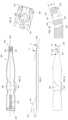
- FIG. 1is a plan view of one example of an implant in accordance with some embodiments
- FIG. 2is a side view of the implant illustrated in FIG. 1 in accordance with some embodiments;
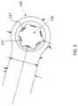
- FIG. 3is a detail view of the enlarged head of an extramedullary portion of the implant illustrated in FIG. 1 in accordance with some embodiments;
- FIG. 4is a plan view of another example of an implant in accordance with some embodiments.
- FIG. 5is a side view of the implant illustrated in FIG. 4 in accordance with some embodiments.
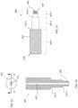
- FIG. 6is a bottom-side plan view of one example of an inserter in accordance with some embodiments.
- FIG. 7is a side view of the inserter illustrated in FIG. 6 in accordance with some embodiments.
- FIG. 8is a top-side plan view of the inserter illustrated in FIG. 6 in accordance with some embodiments.
- FIG. 9is a detailed view of the engagement end of an inserter, taken along line 9 - 9 in FIG. 7 , in accordance with some embodiments;
- FIG. 10is a cross-sectional view, taken along line 10 - 10 in FIG. 8 , in accordance with some embodiments;
- FIG. 11is a side view of one example of a guide tool in accordance with some embodiments.
- FIG. 12is a front side plan view of the guide tool illustrated in FIG. 11 in accordance with some embodiments.
- FIG. 13is a sectional view of the guide tool illustrated in FIG. 11 , taken along line 13 - 13 in FIG. 12 , in accordance with some embodiments;
- FIG. 14is a top-side plan view of one example of a broach in accordance with some embodiments.
- FIG. 15is a side view of the broach illustrated in FIG. 14 in accordance with some embodiments.
- FIG. 16is a bottom-side plan view of the broach illustrated in FIG. 14 in accordance with some embodiments.
- FIG. 17is a side view of one example of a broach insert for a broach in accordance with some embodiments.
- FIG. 18is a top-side plan view of the broach insert shown in FIG. 17 in accordance with some embodiments.
- FIG. 19is an isometric view of an assembly of an implant, an inserter, and a guide in accordance with some embodiments;
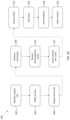
- FIG. 20is a flow diagram of one example of a method of treatment in accordance with some embodiments.
- FIGS. 20 A- 20 Hillustrate various stages of the method of treatment in accordance with FIG. 20 ;
- FIG. 21illustrates one example of an implant joining two bone segments, sections, or fragments in accordance with some embodiments.
- This disclosureprovides implants, systems for installing the implants, and treatment methods for minimally invasive correction of Tailor's bunion (or of an analogous deformity in another joint).
- the drawingsshow application of the implant, inserter, and guide for treating a fifth metatarsal for the correction of Tailor's bunion
- the implant, systems, and methodscan be sized, configured, and tailored to treat other bones.
- the implants, systems, and methodsmay be described as being used to couple together first and second fragments or segments formed from a single bone, it should be understood that the implants, systems and methods may be used to extend across a joint thereby coupling together two adjacent and/or distinct bones (e.g., a metatarsal and a phalange).
- first bone and second bonemay refer to two naturally distinct bones (e.g., a metatarsal and a phalange) and/or to two sections, portions, or fragments operatively formed from a single bone (e.g., a distal fragment and a proximal fragment formed from a metatarsal).
- FIGS. 1 - 3show a first example of the implant 100 .
- FIG. 1is a plan view of the implant 100
- FIG. 2is a medial (or lateral) side view of the implant 100 of FIG. 1 .
- the implant 100is illustrated having a unitary body including an intramedullary portion 110 connected to an extramedullary portion 130 .
- the unitary body of implant 100is configured to attach a first bone section, segment, or fragment to a second bone segment, section, or fragment.
- implant 100may be used to attach a proximal bone segment or fragment PF to a distal bone segment or fragment DF as best seen in FIG. 21 . It should be understood that the implant 100 can be used on either left or right foot.
- the intramedullary portion 110defines a first longitudinal axis 120 , which can be a central axis.
- the intramedullary portion 110is configured for insertion into the first bone section (e.g., proximal fragment PF shown in FIG. 21 ).
- intramedullary portion 110may have a cylindrical geometric configuration with a one or more tapers or bevels 104 at first end (e.g., distal or insertion end) 102 to facilitate insertion of the intramedullary portion 110 into an intramedullary canal formed in a bone segment or fragment as will be discussed in greater detail herein.
- the taper or bevel 104terminates in a blunted tip 106 .
- intramedullary portion 110is shown as being cylindrical, one of ordinary skill in the art will understand that the cross-sectional geometry of intramedullary portion 110 may be polygonal (e.g., triangular, rectangular, pentagonal, etc.) and/or include one or more protrusions or flat surfaces formed thereon to resist rotation of the implant 110 relative to the first bone segment or fragment. In some embodiments, the intramedullary portion 110 may be completely or partially threaded. In some embodiments, the intramedullary portion 110 may include one or more fins or protrusions extending outwardly therefrom to resist rotation of the implant 100 relative to the bone segment, section, or fragment.
- polygonale.g., triangular, rectangular, pentagonal, etc.
- the intramedullary portion 110may be completely or partially threaded.
- the intramedullary portion 110may include one or more fins or protrusions extending outwardly therefrom to resist rotation of the implant 100 relative to the bone segment, section, or fragment
- the extramedullary portion 130includes a bone contacting side or face 132 configured to abut a surface of a second bone section (e.g., a distal fragment DF as shown in FIG. 21 ). As best seen in FIG. 1 , extramedullary portion 130 includes an enlarged head 134 defining a fastener aperture 136 . In some embodiments, the enlarged head 134 has a circular geometry, although one of ordinary skill in the art will understand that enlarged head 134 may have other shapes.
- the at least one fastener aperture 136 defined by enlarged head 134 of extramedullary portion 130defines an aperture axis 138 as best seen in FIG. 2 .
- Fastener aperture 136is sized and configured to receive a bone fastener (e.g., an “Ortholoc® 3DiTM” locking screw sold by Wright Medical Technology, Inc. of Memphis, Tenn.), which may be used to secure the extramedullary portion 130 to the second bone section.
- a bone fastenere.g., an “Ortholoc® 3DiTM” locking screw sold by Wright Medical Technology, Inc. of Memphis, Tenn.
- the fastener aperture 136includes a number of intermittent threads 137 that are formed by first tapping the aperture 136 and then transversely cutting through the threads to form the thread segments or intermittent threads 137 as best seen in FIGS. 1 and 3 .
- six transverse cutsare made to form the intermittent threads 137 ; however, one of ordinary skill in the art will understand that fewer or more transverse cuts can be made.
- the aperture axis 138is oriented obliquely relative to the first longitudinal axis 120 as best seen in FIG. 2 . In other embodiments (not shown), the aperture axis 138 is from about 90 degrees to about 180 degrees from the first longitudinal axis 120 . For example, in some embodiments, the aperture axis 138 is oriented orthogonal to the first longitudinal axis 120 .
- the bone fastenermay be disposed transversely or obliquely, relative to the fastener aperture 136 .
- polyaxial screwscan be inserted at an angle of 0.0 to about 15 degrees with respect to the transverse axis of the fastener aperture 136 .
- polyaxial screwssuch as 3Di locking screws or non-locking screws sold by Wright Medical Technology, Inc. of Memphis, Tenn. may be utilized.
- polyaxial screwsmay be inserted parallel to aperture axis 138 or at an angle (e.g., up to 15 degrees) relative to aperture axis 138 .
- a flat surface 140is formed along a face of extramedullary portion 130 that is disposed opposite bone contacting side or face 132 and extends along at least a portion of the length of intramedullary portion 110 .
- flat surface 140is disposed parallel to bone contacting side or face, which is disposed at an angle with respect longitudinal axis 120 defined by intramedullary portion 110 .
- bone contacting side or face 132 and flat surface 140are not arranged orthogonal or parallel to longitudinal axis 120 , although one of ordinary skill in the art will understand that such arrangements in which bone contacting side or face 132 and flat surface 140 are positioned parallel to longitudinal axis are contemplated.
- the bone contacting side or faceis positioned at an angle of 15 degrees (or 165 degrees) relative to longitudinal axis 120 for correcting the valgus of the fifth metatarsal (metatarsus quintus valgus) at the level of the metatarsal head.
- flat surface 140includes first and second portions, which themselves may be disposed at angles relative to one another (i.e., the first and second portions are not co-planar).
- FIGS. 4 - 5illustrate another example of an implant 200 in accordance with some embodiments.
- FIG. 4is a plan view of the implant 200
- FIG. 5is a medial (or lateral) side view of the implant 200 of FIG. 4 .
- implant 200may have a unitary body including an intramedullary portion 210 that transitions into an extramedullary portion 230 .
- Implant 200is configured to attach a first bone section to a second bone section and can be used on either the left or the right foot.
- the intramedullary portion 210defines a first longitudinal axis 220 , which can be a central axis, extending from first end (e.g., an insertion end) 206 and continuing to extramedullary portion 230 .
- Intramedullary portion 210may have a cylindrical geometric configuration with a one or more tapers or bevels 204 at first end 202 to facilitate insertion of the intramedullary portion 210 into bone segment as will be discussed in greater detail herein.
- taper or bevelterminates at a blade tip 206 that is more narrow and pointed than blunted tip 106 .
- intramedullary portion 210is shown as being cylindrical, one of ordinary skill in the art will understand that the cross-sectional geometry of intramedullary portion 210 may be polygonal and/or include one or more protrusions, extensions, flat surfaces, or other anti-rotation features formed thereon to resist rotation of the implant 210 relative to a bone when implanted. Further, as discussed above with respect to implant 100 , intramedullary portion 210 may be completely or partially threaded, or the intramedullary may including one or more fins or other protrusions extending from an external longitudinal surface thereof to engage the surrounding bone once implanted to resist rotation, improve fixation, and/or improve bone purchase.
- Extramedullary portion 230includes a bone contacting side or face 232 configured to abut a surface of the second bone section. As best seen in FIG. 4 , extramedullary portion 230 includes an enlarged head 234 defining a fastener aperture 236 therethrough. Enlarged head 234 is shown with a circular geometry; however, one of ordinary skill in the art will understand that enlarged head 234 may have other geometrical shapes.
- the at least one fastener aperture 236defines an aperture axis 238 , as best seen in FIG. 5 , which is oriented obliquely relative to the first longitudinal axis 220 .
- Fastener aperture 236is sized and configured to receive a bone fastener, such as an “Ortholoc® 3DiTM” locking screw sold by Wright Medical Technology, Inc. of Memphis, which may be used to secure the extramedullary portion 230 to a bone section.
- a bone fastenersuch as an “Ortholoc® 3DiTM” locking screw sold by Wright Medical Technology, Inc. of Memphis, which may be used to secure the extramedullary portion 230 to a bone section.
- the aperture axis 238is aligned obliquely with the longitudinal axis 220 as shown in FIG. 2 .
- the aperture axis 238is from about 90 degrees to about 180 degrees from the first longitudinal axis 220 .
- the aperture axis 238is oriented orthogonal to the first longitudinal axis 220 .
- the bone fastenermay be disposed transversely or obliquely, relative to the fastener aperture 236 and aperture axis 238 .
- polyaxial screwscan be inserted with an angle of 0.0 to about 15 degrees from the aperture axis 238 .
- a flat surface 240is formed along a face of extramedullary portion 230 that is located on the opposite side of implant 200 as the contacting side or face 232 .
- Flat or planar surface 240extends across extramedullary portion 230 and at least a portion of intramedullary portion 210 .
- flat or planar surface 240is disposed parallel to bone contacting side or face 232 , which is positioned at an angle with respect longitudinal axis 220 such that contacting side or face 232 and flat surface 240 are not arranged orthogonal or parallel to longitudinal axis 220 .
- the contacting side or face 232 and flat surface 240are positioned at an angle of 15 degrees (or 165 degrees) relative to longitudinal axis 220 ; however, a person of ordinary skill in the art will understand that contacting side or face 232 and flat or planar surface 240 may be disposed at other angles (e.g., 5 degrees, 10 degrees, 20 degrees, etc.) relative to longitudinal axis 220 defined by intramedullary portion.
- Implants 100 , 200can comprise a metal, such as titanium, stainless steel, or CoCr.
- the implants 100 , 200can comprise a metal substrate coated with or having an additional layer of hydroxyapatite (HA), titanium plasma spray (TPS)/vacuum plasma spray (VPS), roughened surface of resorbable blast media (RBM), a bioactive glass, an antimicrobial or antibiotic, or strontium.
- the implants 100 , 200can comprise a metal substrate with a composite coating or composite layer including HA on plasma, beads, an irregular sintered coating or TPS on an RBM-prepared substrate.
- the metal substratecan have a porous coating. such as spherical bead, asymmetrical powder, or an irregular particle coating.
- the metal substrate of implants 100 , 200comprises a degradable (resorbable) material, such as a magnesium alloy, which may contain lithium, aluminum, rare earth metals (e.g., neodymium or cerium), manganese, zinc or other metals.
- the resorbable materialcan include, but are not limited to polymer materials including a polylactide, polyglycolide, polycaprolactone, polyvalerolactone, polycarbonates, polyhydroxy butyrates, poly ortho esters, polyurethanes, polyanhydrides, and combinations and copolymers thereof, for example.
- implants 100 , 200comprise a non-absorbable polymer, such as polyethereetherketone (PEEK), or an absorbable polymer composite, such as polylactic-acid (PLLA), a PLLA-beta-tricalcium-phosphate ( ⁇ -TCP) blend, to list only a few possibilities.
- PEEKpolyethereetherketone
- PLLApolylactic-acid
- ⁇ -TCPPLLA-beta-tricalcium-phosphate
- the implants 100 , 200comprise a biologic material.
- the biologic materialcan be a combination of Medical grade ⁇ -TCP granules and rhPDGF-BB solution, such as “AUGMENT®” bone graft material sold by Wright Medical Technology, Inc. of Memphis, Tenn.
- the biologic materialcan be applied, sprayed, or inserted at the wound site for bone in-growth, or can be provided as a coating on the implants or any or all portions of the implant system.
- the biologic materialis a coating containing osteoinductive or osteoconductive biological components.
- the biologic materialcan include bone morphogenetic factors, i.e., growth factors whose activity are specific to bone tissue including, but not limited to, demineralized bone matrix (DBM), bone protein (BP), bone morphogenetic protein (BMP), and mixtures and combinations thereof.
- BBMdemineralized bone matrix
- BPbone protein
- BMPbone morphogenetic protein
- formulations for promoting the attachment of endogenous bonemay comprise bone marrow aspirate, bone marrow concentrate, and mixtures and combinations thereof.
- the configuration of the implants 100 , 200advantageously provide an enhanced fixation of the distal fragment of the fifth metatarsal compared to the conventional buttressing k-wire technique. Further, the ability to use locking screws help prevent dorsal subluxation of the distal fragment as compared to the buttressing k-wire technique.
- an inserter 300may be provided for aiding a surgeon or other individual in implanting one of the implants 100 , 200 in a patient. Such an inserter may be provided in a system or kit in accordance with some embodiments.
- One example of an inserter 300is illustrated in the various views provided in FIGS. 6 - 10 . Referring first to FIGS. 6 - 8 , inserter 300 has a body 302 extending from a first end 304 to a second end 306 and defining a longitudinal axis 308 .
- end 304is an impacting or handle end and end 306 is an engagement end as described below.
- impacting endincludes a flange 310 that extends in a perpendicular direction with respect to the longitudinal axis 308 defined by inserter 300 .
- Flange 310includes an impacting surface 312 , which is sized and structured to be impacted by a hand, mallet, hammer, or other impacting tool as will be understood by one of ordinary skill in the art.
- flange 310is supported or reinforced by one or more reinforcing ribs 314 .
- Reinforcing rib(s) 314may have triangular geometry as shown in FIG. 7 , although other geometric configurations also are possible.
- one or more indents 316may be provided along the length of the body 302 .
- Indents 316may be provided to enhance the ability of a surgeon or other user to grasp and manipulate inserter 300 .
- indents 316have a rounded or curved configuration to provide for enhanced ergonomics.
- Engagement end 306is structured to engage an implant 100 , 200 and defines a hole 318 ( FIGS. 6 , 8 , and 9 ) and a pocket or channel 320 ( FIGS. 6 , 9 , and 10 ).
- hole 318is dimensioned to provide clearance for receiving a mating end of a drill guide as discussed in greater detail herein.
- Pocket 320is shaped and dimensioned to receive the enlarged head 134 , 234 of extramedullary portion 130 , 230 therein such that, when the enlarged head 124 , 234 is received within pocket 320 , the wall(s) 322 defining pocket 320 snugly engages the outer surface of enlarged head 134 , 234 of implant 100 , 200 to resist rotation of the implant 100 , 200 relative to inserter 300 .
- engagement end 306may be angled relative to the longitudinal axis 308 of inserter 300 .
- the angle of engagement end 306corresponds to the angle of the extramedullary portion 130 , 230 of the implant 100 , 200 .
- hole 318defines an axis 324 that is arrange on body 302 of inserter 300 such that, when implant 100 , 200 is engaged by engagement end 306 of inserter 300 , the axis 324 is aligned with aperture axis 138 , 238 .
- inserter 300defines a hole or slot 330 along its length.
- the hole or slot 330is sized and structured to receive a k-wire therein to temporarily fixate a distal fragment to another bone, e.g., the fourth metatarsal, as described in greater detail below.
- an axis defined by hole or slot 330is parallel to the axis 324 defined by hole 318 .
- hole or slot 330may be oriented at other angles relative to the axis 324 defined by hole 318 .
- Inserter 300may be provided in a wide variety of materials, including metal and/or plastic. In some embodiments, inserter 300 is formed from a material that may be sterilized such that the inserter may be provided in a sterilized package along with one or more implants and/or other devices described herein.
- FIGS. 11 - 13illustrate one example of a guide tool 400 in accordance with some embodiments.
- guide 400includes a body 402 that extends from a coupling end 404 to a second end 406 .
- the body 402 of guide 400includes one or more shoulders 410 - 1 , 410 - 2 due to the body 402 including one or more segments having a reduced diameter relative to an adjacent segment. As shown in FIG. 11 , guide 400 includes a body 402 that extends from a coupling end 404 to a second end 406 .
- the body 402 of guide 400includes one or more shoulders 410 - 1 , 410 - 2 due to the body 402 including one or more segments having a reduced diameter relative to an adjacent segment. As shown in FIG.
- the guide 400is provided with three body segments 402 - 1 , 402 - 2 , and 402 - 3 , with a shoulder 410 - 1 provided at the interface between body segments 402 - 1 and 402 - 2 and a shoulder 410 - 2 provided at the interface between body segments 402 - 2 and 402 - 3 .
- drill guide 400may be provided with fewer segments and/or shoulders.
- distal segment 402 - 3 at coupling end 404is at least partially threaded.
- threads 408may extend partially or entirely along segment 402 - 3 .
- Body segment 402 - 2which is disposed between body segment 402 - 1 and body segment 402 - 3 , may be provided with a smooth external surface.
- body segment 402 - 3has a cross-sectional diameter that is sized to be received within hole 318 of inserter 300 and has a thickness or width of segment 402 - 3 (e.g., the distance between shoulder 410 - 2 and end 404 ) dimensioned relative to the depth of hole 318 defined by inserter 300 (e.g., the distance D 1 in FIG. 10 ) such that shoulder 410 - 2 is approximately planar with wall 328 of inserter 300 when the partially threaded portion of distal segment 402 - 3 is tightened onto the threaded aperture 136 , 236 .
- a thickness or width of segment 402 - 3e.g., the distance between shoulder 410 - 2 and end 404
- the depth of hole 318 defined by inserter 300e.g., the distance D 1 in FIG. 10
- Body segment 402 - 1which in some embodiments has the greatest cross-sectional diameter, may include a surface texture formed on an external surface thereof to facilitate manipulate by a user.
- the external surface 402 - 1may include knurling, ridges, grooves, or any other suitable surface texturing as will be understood by one of ordinary skill in the art.
- drill guide 400defines a central guide hole 412 that extends through the entirety of body 402 .
- Guide hole 412is sized and dimensioned to guide a suitable drill or other drilling or cutting tool for creating a pilot hole in a bone as discussed in greater detail below.
- FIGS. 14 - 18illustrate one example of a broach 500 including a handle 502 and a blade insert 504 , in accordance with some embodiments.
- the handle 502includes a body 506 extending from a first end 510 to a second end 512 substantially along a central longitudinal axis 514 .
- the handle 502defines at least one aperture 516 along its length extending from a first (e.g., upper) surface 518 to the second (e.g., lower or bottom) surface 520 .
- the handle 502defines a slot or channel (not shown) inwardly extending from a first end 512 into the body 506 sized and configured to receive a portion of an insert 504 therein.
- the channelis sized and configured to receive a portion of an insert 504 such that the aperture 516 is aligned with apertures formed in the insert 504 (as described in greater detail below) when the insert 504 is inserted into the channel.
- the insert 504is over-molded by handle 502 .
- End 510 of body 502includes a flange 520 that extends perpendicularly with respect to the longitudinal axis 514 defined by body 502 .
- Flange 520includes an impacting surface 522 .
- Impacting surface 522is sized and structured to be impacted by a hand, mallet, hammer, or other impacting tool as will be understood by one of ordinary skill in the art.
- flange 522is supported or reinforced by one or more reinforcing ribs 524 .
- Reinforcing rib(s) 524may have triangular geometry as illustrated in FIG. 15 , although a person of ordinary skill in the art will understand that other geometric configurations also are possible.
- one or more indents 526may be provided along the length of the body 502 .
- Indents 526may be provided to enhance the ability of a surgeon or other user to grasp and manipulate inserter broach 500 .
- indents 526have a rounded or curved configuration to provide for enhanced ergonomics.
- Insert 504includes a body 530 extending from a first end 532 to a second end 534 substantially along a central longitudinal axis 536 .
- the insert 504includes a first portion 538 configured to be coupled to a handle 502 and a second portion 540 configured to be at least partially inserted into a cut formed in a bone, such as a metatarsal, including the fifth metatarsal.
- Aperture 542is positioned along the length of body 530 and enables over-molding material to flow within aperture 542 .
- one or more additional apertures 548are defined by body 530 and are positioned along the body 530 of insert 504 such that, when the insert 504 is properly received within handle 502 , apertures 548 are aligned with holes 516 .
- the alignment of holes 516 , 548provides a passageway through broach 500 and enables a k-wire, pin, or other tool to be inserted through broach to provide some additional leverage for a user to dislodge broach from an intramedullary canal.
- the insert 504is configured to be coupled to the handle 502 to define a broach 500 configured to assist in the preparation of an intramedullary canal in a bone, such as a metatarsal, including a fifth metatarsal.
- the second portion 540 of the insert 504is configured to be inserted into a bone and leveraged to offset a first portion of a bone with a second portion of the bone to prepare an intramedullary canal.
- a leading edge 550 of the insert 504is configured to facilitate insertion into the bone.
- the leading edge 550can be sharpened to define a cutting edge and/or include a thickness less than the thickness of the insert 504 .
- the broach handle 502(or a portion thereof) can be formed by injection molding material such as polycarbonate (PC), polyamide (e.g., Nylon), polyarylamide (e.g., PARA, Ixef, etc.), acrylonitrile butadiene styrene (ABS), and/or any other suitable injection molding material.
- the injection moldingcan be formed over one or more structural features, such as ribs, lattice, etc. or surface features, such as knurling, plasma spray, etc., to provide increased strength and/or to withstand forces applied during insertion of the broach 500 and formation of an intramedullary canal in a bone.
- the insert 504(or a portion thereof) is formed of a metal material formed by any suitable process, such as by stamping, bending, drilling, milling, turning, etc.
- the implant 100 , 200 , inserter 300 , and guide 400are provided in an assembled configuration, such as the configuration shown in FIG. 19 .
- the assembly 10may be provided in sterilized package with each component having been sterilized after assemblage and packaging.
- the extramedullary portion 130 , 230 of implant 100 , 200is received within pocket 320 of inserter 300 such that intramedullary portion 110 , 210 of implant is exposed by and extends away from end 306 of inserter 300 .
- aperture hole 136 , 236 of implant 100 , 200is aligned with hole 318 of inserter.
- Guide 400is engaged with implant 100 , 200 and inserter 300 by inserting body segment 402 - 3 into the aligned holes 136 (or 236 ) and 318 and then engaging the threads 408 of guide 400 with the thread segments 137 (or 237 ) of the implant.
- threads 408 of guide 400are engaged with thread segments 137 (or 237 ) by rotating guide body 402 relative to implant 100 , 200 and inserter 300 .
- the various implants and/or toolsare provided in a surgical kit in which each of the various components is individually placed within a sterilized package in a disassembled configuration and sterilized.
- one or more implantsmay be provided in the kit with a correspondingly sized inserter, guide tool, and fastener(s).
- the implantmay be provided in 2 mm, 3 mm, 4 mm, 5 mm, and other cross-sectional diameters with inserters, guide tools, fasteners, and k-wire(s) configured for implanting these implants.
- Systemsmay also be provided in which one or more of the various components are separately packaged and then gathered at the time of surgery as will be understood by one of ordinary skill in the art.
- Various combinations of kits and/or individual componentsmay be gathered together to provide a system.
- One of ordinary skill in the artwill understand that there are numerous ways to provide a kit, system, and/or assembly and the foregoing examples are not limiting.
- FIG. 20is a flow chart of one example of a treatment method 600 in accordance with some embodiments, with FIGS. 20 A- 20 G illustrating various steps performed of the method.
- a patientis placed in a supine position on an operating table, and the metaphysis of the fifth metatarsal (or other targeted bone or implant site) is identified.
- a longitudinal incisionis made proximal from the metaphysis of the fifth metatarsal head M, as shown in FIG. 20 A , and extending distally.
- the periosteum around the metaphysisis elevated using an elevator to allow for extracapsular osteotomy.
- the lateral eminencemay be shaved down at block 606 .
- the lateral eminencemay be shaved down using a wedge burr or other suitable cutting or grinding tool as will be understood by one of ordinary skill in the art.
- an osteotomyis performed.
- a transverse osteotomyis made using a Shannon burr B or saw at the level of the metaphysis.
- the burr Bmay be plunged bi-cortically and then swept dorsally and plantarly to complete the cut.
- the plane of the cutmay be perpendicular to the axis of the fifth metatarsal or to the axis of the fourth metatarsal at the osteotomy site.
- a chevron osteotomyis performed instead of a transverse osteotomy.
- FIG. 20 Billustrates an osteotomy being performed using a burr B in accordance with some embodiments.
- the intramedullary canal of the proximal fragment PFis broached.
- an initial broaching of the intramedullary canalmay be performed using an elevator E after having moved the distal fragment DF out of the way as shown in FIG. 20 C .
- FIGS. 20 D and 20 Eillustrate the broach 500 being used to broach the intramedullary canal of proximal fragment PF.
- a mallet, hammer, or other impaction devicemay be used to achieve the desired broaching as will be understood by one of ordinary skill in the art.
- the impaction devicemay be used to hit impact surface 522 of broach 500 until the distal end of the broach handle 512 nearly touches the distal end of the proximal fragment PF.
- AP and ML radiographsmay be checked to determine if the size of the broach adequately fills the intramedullary canal. If the broach does adequately fill the intramedullary canal, then the broach is removed. If the broach does not adequately fill the intramedullary canal, then a larger broach may be selected and the steps at block 610 may be repeated.
- the implant 100 , 200is inserted into the broached intramedullary canal.
- the implant 100 , 200is pre-attached to inserter 300 and guide to provide the assembly 10 shown in FIG. 19 and as described above.
- the inserter 300is used to guide implant 100 , 200 into the broached intramedullary canal with the insertion end 106 , 206 being introduced into the canal first as shown in FIG. 20 F .
- a mallet(not shown) may be used to seat the implant 100 , 200 fully (or properly) within the broached intramedullary canal.
- the malletmay be used to tap on the impact surface 312 of inserter 300 until the inserter nearly touches the distal end of the proximal fragment.
- a k-wiremay be inserted through the hole or slot defined along the length of the inserter 300 , through the distal fragment DF, and into a second bone, such as a fourth metatarsal.
- FIG. 20 Gillustrates the k-wire K being inserted through a hole or slot formed in inserter 300 and passing through the distal fragment DF and into second bone B 2 .
- a surgeonmay pinch medially of the distal fragment to ensure that the distal fragment is properly aligned in the dorsal-plantar direction and that the distal fragment laterally contacts the implant 100 , 200 . This pinching may be performed prior to k-wire insertion and/or as the k-wire is inserted.
- drilling for placement of the distal fragment screwis performed.
- the distal fragmentis drilled bi-cortically through the drill guide 400 as shown in FIG. 20 H .
- the drill guide 400may be threaded directly into the thread segments 137 , 237 within the fastener aperture 136 , 236 having removed the inserter 300 .
- the drillingmay be performed while the inserter 300 is still engaged with drill guide 400 and implant 100 , 200 as shown in FIG. 20 H .
- the drill guide 400may be removed from its engagement with the assembly 10 of the implant 100 , 200 and inserter 300 .
- the inserter 300may be removed from its engagement with the implant 100 , 200 .
- a fastener 700is selected and used to secure the implant 100 , 200 to the distal bone fragment DF.
- a surgeonmay use a locking or non-locking screw and inserts the selected fastener through fastener aperture 136 , 236 and into the pre-drilled bone fragment.
- the k-wire K, if used, and inserter 300if not yet removed, may then be removed.
- the incisionis closed.
- the distal-lateral corner of the proximal fragmentis smoothed, using a burr, rasp, or other appropriate surgical tool, prior to closing the incision to avoid a sharp prominence after closure.
- One or more stitchesalso may be used to close the incision.
Landscapes
- Health & Medical Sciences (AREA)
- Orthopedic Medicine & Surgery (AREA)
- Life Sciences & Earth Sciences (AREA)
- Surgery (AREA)
- General Health & Medical Sciences (AREA)
- Veterinary Medicine (AREA)
- Engineering & Computer Science (AREA)
- Biomedical Technology (AREA)
- Heart & Thoracic Surgery (AREA)
- Public Health (AREA)
- Animal Behavior & Ethology (AREA)
- Oral & Maxillofacial Surgery (AREA)
- Molecular Biology (AREA)
- Medical Informatics (AREA)
- Nuclear Medicine, Radiotherapy & Molecular Imaging (AREA)
- Transplantation (AREA)
- Cardiology (AREA)
- Vascular Medicine (AREA)
- Dentistry (AREA)
- Physical Education & Sports Medicine (AREA)
- Neurology (AREA)
- Prostheses (AREA)
- Surgical Instruments (AREA)
Abstract
Description
Claims (14)
Priority Applications (2)
| Application Number | Priority Date | Filing Date | Title |
|---|---|---|---|
| US16/170,250US11660201B2 (en) | 2018-10-25 | 2018-10-25 | Systems, apparatuses, and methods for correcting a bone defect |
| US18/301,512US20230248530A1 (en) | 2018-10-25 | 2023-04-17 | Systems, apparatuses, and methods for correcting a bone defect |
Applications Claiming Priority (1)
| Application Number | Priority Date | Filing Date | Title |
|---|---|---|---|
| US16/170,250US11660201B2 (en) | 2018-10-25 | 2018-10-25 | Systems, apparatuses, and methods for correcting a bone defect |
Related Child Applications (1)
| Application Number | Title | Priority Date | Filing Date |
|---|---|---|---|
| US18/301,512DivisionUS20230248530A1 (en) | 2018-10-25 | 2023-04-17 | Systems, apparatuses, and methods for correcting a bone defect |
Publications (2)
| Publication Number | Publication Date |
|---|---|
| US20200129304A1 US20200129304A1 (en) | 2020-04-30 |
| US11660201B2true US11660201B2 (en) | 2023-05-30 |
Family
ID=70326161
Family Applications (2)
| Application Number | Title | Priority Date | Filing Date |
|---|---|---|---|
| US16/170,250Active2039-03-26US11660201B2 (en) | 2018-10-25 | 2018-10-25 | Systems, apparatuses, and methods for correcting a bone defect |
| US18/301,512PendingUS20230248530A1 (en) | 2018-10-25 | 2023-04-17 | Systems, apparatuses, and methods for correcting a bone defect |
Family Applications After (1)
| Application Number | Title | Priority Date | Filing Date |
|---|---|---|---|
| US18/301,512PendingUS20230248530A1 (en) | 2018-10-25 | 2023-04-17 | Systems, apparatuses, and methods for correcting a bone defect |
Country Status (1)
| Country | Link |
|---|---|
| US (2) | US11660201B2 (en) |
Families Citing this family (4)
| Publication number | Priority date | Publication date | Assignee | Title |
|---|---|---|---|---|
| FR3099875A1 (en)* | 2019-08-12 | 2021-02-19 | Novastep | Intramedullary implant for transverse osteotomy |
| US12295589B2 (en) | 2019-12-12 | 2025-05-13 | Relja Innovations, Llc | Method, surgical apparatus, and surgical implant for minimally invasive surgical procedures |
| US11883075B2 (en) | 2021-11-08 | 2024-01-30 | Relja Innovations, Llc | Device and surgical technique for foot surgery |
| US20250049443A1 (en)* | 2023-07-14 | 2025-02-13 | Treace Medical Concepts, Inc. | Distal osteotomy metatarsal correction systems and techniques |
Citations (69)
| Publication number | Priority date | Publication date | Assignee | Title |
|---|---|---|---|---|
| US2612159A (en) | 1949-03-01 | 1952-09-30 | Marie B Collison | Trochanteric plate for bone surgery |
| US6203545B1 (en) | 1996-03-26 | 2001-03-20 | Waldemar Link (Gmbh & Co.) | Implant for fixing bone fragments after an osteotomy |
| US6248109B1 (en) | 1998-07-30 | 2001-06-19 | Waldemar Link (Gmbh & Co.) | Implant for interconnecting two bone fragments |
| US6689136B2 (en) | 2001-08-21 | 2004-02-10 | Waldemar Link Gmbh & Co. | Implant for fixing two bone fragments to each other |
| US6706046B2 (en) | 2000-02-01 | 2004-03-16 | Hand Innovations, Inc. | Intramedullary fixation device for metaphyseal long bone fractures and methods of using the same |
| US20050033302A1 (en) | 2002-03-12 | 2005-02-10 | Erich Frank | Implant for the dynamic fixation of a corrective osteotomy |
| US6926720B2 (en) | 2003-10-15 | 2005-08-09 | Hand Innovations, Llc | Jig assembly for implantation of a fracture fixation device |
| US20060015123A1 (en) | 2004-07-15 | 2006-01-19 | Wright Medical Technology, Inc. | Guide assembly for intramedullary fixation and method of using the same |
| US20060149257A1 (en) | 2002-05-30 | 2006-07-06 | Orbay Jorge L | Fracture fixation device |
| US20060161156A1 (en) | 2002-05-30 | 2006-07-20 | Orbay Jorge L | Fracture fixation device |
| US20060206044A1 (en) | 2002-08-10 | 2006-09-14 | Simon Willliam H | Method and apparatus for repairing the mid-food region via an intramedullary nail |
| US20070083202A1 (en) | 2005-09-20 | 2007-04-12 | Donald Eli Running | Intramedullary bone plate with sheath |
| US20070191855A1 (en)* | 2006-01-27 | 2007-08-16 | Orbay Jorge L | Fracture fixation device and implantation jig therefor |
| US20070233134A1 (en)* | 2006-03-06 | 2007-10-04 | Howmedica Osteonics Corp. | Compound offset handle |
| US20090036931A1 (en) | 2007-08-04 | 2009-02-05 | Normed Medizin-Technik Vertriebs-Gmbh | Foot surgery bone plate, and system comprising bone plate and insertion aid |
| US20090069812A1 (en) | 2007-06-15 | 2009-03-12 | Acumed Llc | Rib fixation with an intramedullary nail |
| US20090118770A1 (en) | 2007-11-02 | 2009-05-07 | Sixto Jr Robert | Fracture Fixation Plate for the Olecranon of the Proximal Ulna |
| US7563263B2 (en) | 2000-02-01 | 2009-07-21 | Depuy Products, Inc. | Intramedullary fixation device for metaphyseal long bone fractures |
| EP2228026A1 (en)* | 2009-03-10 | 2010-09-15 | Giuseppe Lodola | A stabilizer device for the mutual elastic stabilization of two bone segments |
| US20100274293A1 (en) | 2009-04-28 | 2010-10-28 | Osteomed L.P. | Bone Plate with a Transfixation Screw Hole |
| WO2011002903A2 (en) | 2009-06-30 | 2011-01-06 | Kohsuke Watanabe | Orthopaedic implant and fastener assembly |
| US7927341B2 (en) | 2005-01-28 | 2011-04-19 | Depuy Products, Inc. | Nail plate and jig therefor |
| US7938850B2 (en) | 2002-05-30 | 2011-05-10 | Depuy Products, Inc. | Nail plate |
| US20110137313A1 (en) | 2008-08-12 | 2011-06-09 | Tantum Ag | Short pin for taking care of epiphysis fractures |
| US8083783B2 (en) | 2005-04-08 | 2011-12-27 | Swemac Innovation Ab | Surgical fixation pin |
| US20120016426A1 (en) | 2009-03-17 | 2012-01-19 | Bonfix Ltd. | Hallux abducto valgus assemblies |
| US8167918B2 (en) | 2008-02-19 | 2012-05-01 | Orthohelix Surgical Designs, Inc. | Orthopedic plate for use in the MTP joint |
| US20130066383A1 (en) | 2010-10-10 | 2013-03-14 | Gregory S. Anderson | Arthrodesis implant and buttressing apparatus and method |
| US20130123862A1 (en) | 2010-10-10 | 2013-05-16 | Gregory Anderson | Arthrodesis implant and buttressing apparatus and method |
| US8608783B2 (en) | 2008-05-08 | 2013-12-17 | The Cleveland Clinic Foundation | Bone plate with flange member and methods of use thereof |
| US8628533B2 (en) | 2008-05-08 | 2014-01-14 | The Cleveland Clinic Foundation | Bone plate with reduction aids and methods of use thereof |
| US20140018812A1 (en) | 2012-07-11 | 2014-01-16 | The Cleveland Clinic Foundation | Arthroplasty device |
| US8685024B2 (en) | 2010-04-14 | 2014-04-01 | Arrowhead Medical Device Technologies, Llc | Intramedullary fixation device and methods for bone fixation and stabilization |
| US20140107798A1 (en) | 2012-04-05 | 2014-04-17 | Orthohelix Surgical Designs, Inc. | Lateral ankle fusion plate system and jig, and method for use therewith |
| US8715325B2 (en) | 2009-02-19 | 2014-05-06 | Nextremity Solutions, Inc. | Bone joining apparatus and method |
| US8753343B2 (en) | 2004-12-23 | 2014-06-17 | Hans Ulrich Staeubli | Bone fixing device |
| US20140180348A1 (en) | 2012-12-21 | 2014-06-26 | Wright Medical Technology, Inc. | Trajectory guide |
| WO2014105750A1 (en) | 2012-12-28 | 2014-07-03 | Paragon 28, Inc. | Alignment guide apparatus, method and system |
| US20140243837A1 (en) | 2013-02-27 | 2014-08-28 | Biomet C.V. | Jig with Guide Adapted to Lock Relative to Both of Threaded Holes and Non-Threaded Slots in a Bone Plate |
| US20140277178A1 (en) | 2013-03-13 | 2014-09-18 | Wright Medical Technology, Inc. | Posterior Ankle Fusion Plate |
| US8858602B2 (en) | 2011-02-01 | 2014-10-14 | Nextremity Solutions, Inc. | Bone defect repair device and method |
| US8926612B2 (en) | 2012-03-08 | 2015-01-06 | The Cleveland Clinic Foundation | Arthrodesis apparatus and method |
| CN204072294U (en) | 2014-08-07 | 2015-01-07 | 上海市第一人民医院 | A kind of intramedullary pin for implanting humerus medullary cavity |
| US20150032168A1 (en) | 2012-02-16 | 2015-01-29 | Paragon 28, Inc. | Charco-resis implant, alignment instrument, system and method of use |
| US8998999B2 (en) | 2011-11-17 | 2015-04-07 | Orthohelix Surgical Designs, Inc. | Hammertoe implant |
| US9017329B2 (en) | 2008-06-24 | 2015-04-28 | Extremity Medical, Llc | Intramedullary fixation assembly and method of use |
| US20150164565A1 (en) | 2009-07-09 | 2015-06-18 | Orthohelix Surgical Designs, Inc. | Osteotomy plate, plate driver and method for their use |
| CN204655083U (en) | 2015-02-13 | 2015-09-23 | 爱派司生技股份有限公司 | Hallux Immobilizer |
| US9226783B2 (en) | 2008-07-09 | 2016-01-05 | Icon Orthopaedic Concepts, Llc | Ankle arthrodesis nail and outrigger assembly |
| US20160051295A1 (en) | 2013-04-11 | 2016-02-25 | K. N. Medical. Co., Ltd. | Osteosynthesis device |
| US20160074079A1 (en) | 2013-04-29 | 2016-03-17 | Biotech Ortho | Osteotomy device, in particular for performing extreme scarf osteotomy in the treatment of severe hallux valgus |
| US20160143675A1 (en) | 2014-11-24 | 2016-05-26 | Intai Technology Corporation | Rear-retaining structure for dynamic hip screw |
| US20160199110A1 (en) | 2015-01-08 | 2016-07-14 | Neutin Orthopedics, LLC | Fixed bone plate for rotational and translational first metatarsal osteotomy procedures |
| US9452002B2 (en) | 2013-03-13 | 2016-09-27 | Arrowhead Medical Device Technologies, Llc | Hammertoe implant with enhanced gripping surfaces |
| CN105997215A (en) | 2016-06-29 | 2016-10-12 | 江苏艾迪尔医疗科技股份有限公司 | Tibia inverted intramedullary nail |
| US9486258B2 (en) | 2013-03-13 | 2016-11-08 | Arrowhead Medical Device Technologies, Llc | Hammertoe implant with asymmetrical head |
| US20160354127A1 (en)* | 2015-06-08 | 2016-12-08 | Andrew Lundquist | Combined Intramedullary - Extramedullary Bone Stabilization and Alignment System |
| US9554916B2 (en) | 2014-06-04 | 2017-01-31 | Sarah Miller | Apparatus and method for replacement of a metatarsophalangeal joint with interphalangeal fusion |
| US9597130B2 (en) | 2010-04-27 | 2017-03-21 | DePuy Synthes Products, Inc. | Bone fixation system including K-wire compression |
| US9615873B2 (en) | 2009-02-19 | 2017-04-11 | Nextremity Solutions, Inc. | Bone joining apparatus and method |
| US9642656B2 (en) | 2012-03-08 | 2017-05-09 | Zimmer Gmbh | Intramedullary locking bone screw for fixing the metatarsophalangeal joint of the big toe in foot surgery |
| US20170196602A1 (en)* | 2015-06-08 | 2017-07-13 | Andrew Lundquist | Combined Intramedullary - Extramedullary Bone Stabilization and Alignment System |
| US9717543B2 (en) | 2013-03-13 | 2017-08-01 | Arrowhead Medical Device Technologies, Llc | Methods and implants for treating hammertoe and other deformities |
| US20170245902A1 (en)* | 2014-09-19 | 2017-08-31 | Crossroads Extremity Systems, Llc | Bone fixation implant and means of fixation |
| US20180028242A1 (en)* | 2016-07-29 | 2018-02-01 | Additive Orthopaedics, LLC | Bone fixation device and method of use |
| US9907562B2 (en) | 2013-03-15 | 2018-03-06 | Paragon 28, Inc. | Intramedullary nail fixation guides, devices and methods of use |
| US9943347B2 (en) | 2014-07-22 | 2018-04-17 | Virginia Commonwealth University | Medial column (MECO) fixation device, method, and system |
| US10080597B2 (en) | 2014-12-19 | 2018-09-25 | Wright Medical Technology, Inc. | Intramedullary anchor for interphalangeal arthrodesis |
| US20190125418A1 (en)* | 2017-10-27 | 2019-05-02 | Wright Medical Technology, Inc. | Implant with intramedullary portion and offset extramedullary portion |
- 2018
- 2018-10-25USUS16/170,250patent/US11660201B2/enactiveActive
- 2023
- 2023-04-17USUS18/301,512patent/US20230248530A1/enactivePending
Patent Citations (84)
| Publication number | Priority date | Publication date | Assignee | Title |
|---|---|---|---|---|
| US2612159A (en) | 1949-03-01 | 1952-09-30 | Marie B Collison | Trochanteric plate for bone surgery |
| US6203545B1 (en) | 1996-03-26 | 2001-03-20 | Waldemar Link (Gmbh & Co.) | Implant for fixing bone fragments after an osteotomy |
| US6248109B1 (en) | 1998-07-30 | 2001-06-19 | Waldemar Link (Gmbh & Co.) | Implant for interconnecting two bone fragments |
| US20060100624A1 (en) | 2000-02-01 | 2006-05-11 | Orbay Jorge L | Intramedullary fixation device for metaphyseal long bone fractures |
| US6706046B2 (en) | 2000-02-01 | 2004-03-16 | Hand Innovations, Inc. | Intramedullary fixation device for metaphyseal long bone fractures and methods of using the same |
| US7727264B2 (en) | 2000-02-01 | 2010-06-01 | Depuy Products, Inc. | Intramedullary fixation device for metaphyseal long bone fractures |
| US7563263B2 (en) | 2000-02-01 | 2009-07-21 | Depuy Products, Inc. | Intramedullary fixation device for metaphyseal long bone fractures |
| US6689136B2 (en) | 2001-08-21 | 2004-02-10 | Waldemar Link Gmbh & Co. | Implant for fixing two bone fragments to each other |
| US20050033302A1 (en) | 2002-03-12 | 2005-02-10 | Erich Frank | Implant for the dynamic fixation of a corrective osteotomy |
| US20060161156A1 (en) | 2002-05-30 | 2006-07-20 | Orbay Jorge L | Fracture fixation device |
| US20060149257A1 (en) | 2002-05-30 | 2006-07-06 | Orbay Jorge L | Fracture fixation device |
| US7938850B2 (en) | 2002-05-30 | 2011-05-10 | Depuy Products, Inc. | Nail plate |
| US20060206044A1 (en) | 2002-08-10 | 2006-09-14 | Simon Willliam H | Method and apparatus for repairing the mid-food region via an intramedullary nail |
| US9867642B2 (en) | 2002-08-10 | 2018-01-16 | Howmedica Osteonics Corp. | Method and apparatus for repairing the mid-foot region via an intramedullary nail |
| US20160157902A1 (en) | 2002-08-10 | 2016-06-09 | Howmedica Osteonics Corp. | Method and Apparatus for Repairing the Mid-Foot Region Via and Intramedullary Nail |
| US9788871B2 (en) | 2002-08-10 | 2017-10-17 | Howmedica Osteonics Corp. | Method and apparatus for repairing the mid-foot region via an intramedullary nail |
| US20160157900A1 (en) | 2002-08-10 | 2016-06-09 | Howmedica Osteonics Corp. | Method and Apparatus for Repairing the Mid-Foot Region Via an Intramedullary Nail |
| US6926720B2 (en) | 2003-10-15 | 2005-08-09 | Hand Innovations, Llc | Jig assembly for implantation of a fracture fixation device |
| CN101043854A (en) | 2004-07-15 | 2007-09-26 | 瑞特医疗技术公司 | Intramedullary fixation components and devices |
| US20060015123A1 (en) | 2004-07-15 | 2006-01-19 | Wright Medical Technology, Inc. | Guide assembly for intramedullary fixation and method of using the same |
| US8753343B2 (en) | 2004-12-23 | 2014-06-17 | Hans Ulrich Staeubli | Bone fixing device |
| US7927341B2 (en) | 2005-01-28 | 2011-04-19 | Depuy Products, Inc. | Nail plate and jig therefor |
| US8083783B2 (en) | 2005-04-08 | 2011-12-27 | Swemac Innovation Ab | Surgical fixation pin |
| US20070083202A1 (en) | 2005-09-20 | 2007-04-12 | Donald Eli Running | Intramedullary bone plate with sheath |
| US7686808B2 (en) | 2006-01-27 | 2010-03-30 | Depuy Products, Inc. | Fracture fixation device and implantation jig therefor |
| US20070191855A1 (en)* | 2006-01-27 | 2007-08-16 | Orbay Jorge L | Fracture fixation device and implantation jig therefor |
| US20070233134A1 (en)* | 2006-03-06 | 2007-10-04 | Howmedica Osteonics Corp. | Compound offset handle |
| US20090069812A1 (en) | 2007-06-15 | 2009-03-12 | Acumed Llc | Rib fixation with an intramedullary nail |
| US20090036931A1 (en) | 2007-08-04 | 2009-02-05 | Normed Medizin-Technik Vertriebs-Gmbh | Foot surgery bone plate, and system comprising bone plate and insertion aid |
| US20090118769A1 (en) | 2007-11-02 | 2009-05-07 | Sixto Jr Robert | Fracture Fixation Plate for the Proximal Radius |
| US20090118770A1 (en) | 2007-11-02 | 2009-05-07 | Sixto Jr Robert | Fracture Fixation Plate for the Olecranon of the Proximal Ulna |
| US8167918B2 (en) | 2008-02-19 | 2012-05-01 | Orthohelix Surgical Designs, Inc. | Orthopedic plate for use in the MTP joint |
| US8608783B2 (en) | 2008-05-08 | 2013-12-17 | The Cleveland Clinic Foundation | Bone plate with flange member and methods of use thereof |
| US8628533B2 (en) | 2008-05-08 | 2014-01-14 | The Cleveland Clinic Foundation | Bone plate with reduction aids and methods of use thereof |
| US9017329B2 (en) | 2008-06-24 | 2015-04-28 | Extremity Medical, Llc | Intramedullary fixation assembly and method of use |
| US9226783B2 (en) | 2008-07-09 | 2016-01-05 | Icon Orthopaedic Concepts, Llc | Ankle arthrodesis nail and outrigger assembly |
| US20110137313A1 (en) | 2008-08-12 | 2011-06-09 | Tantum Ag | Short pin for taking care of epiphysis fractures |
| US9615873B2 (en) | 2009-02-19 | 2017-04-11 | Nextremity Solutions, Inc. | Bone joining apparatus and method |
| US8715325B2 (en) | 2009-02-19 | 2014-05-06 | Nextremity Solutions, Inc. | Bone joining apparatus and method |
| EP2228026A1 (en)* | 2009-03-10 | 2010-09-15 | Giuseppe Lodola | A stabilizer device for the mutual elastic stabilization of two bone segments |
| US20120016426A1 (en) | 2009-03-17 | 2012-01-19 | Bonfix Ltd. | Hallux abducto valgus assemblies |
| JP2015044053A (en) | 2009-04-28 | 2015-03-12 | オステオメド エルエルシー | Bone plate with transfixation screw hole |
| US20100274293A1 (en) | 2009-04-28 | 2010-10-28 | Osteomed L.P. | Bone Plate with a Transfixation Screw Hole |
| JP2015155032A (en) | 2009-06-30 | 2015-08-27 | スミス アンド ネフュー インコーポレーテッド | Orthopedic graft and fastener assembly |
| WO2011002903A2 (en) | 2009-06-30 | 2011-01-06 | Kohsuke Watanabe | Orthopaedic implant and fastener assembly |
| US20150164565A1 (en) | 2009-07-09 | 2015-06-18 | Orthohelix Surgical Designs, Inc. | Osteotomy plate, plate driver and method for their use |
| US9629671B2 (en) | 2010-04-14 | 2017-04-25 | Arrowhead Medical Device Technologies, Llc | Intramedullary fixation device and methods for bone fixation and stabilization |
| US8888778B2 (en) | 2010-04-14 | 2014-11-18 | Arrowhead Medical Device Technologies, Llc | Intramedullary fixation device and methods for bone fixation and stabilization |
| US8685024B2 (en) | 2010-04-14 | 2014-04-01 | Arrowhead Medical Device Technologies, Llc | Intramedullary fixation device and methods for bone fixation and stabilization |
| US9597130B2 (en) | 2010-04-27 | 2017-03-21 | DePuy Synthes Products, Inc. | Bone fixation system including K-wire compression |
| US20130123862A1 (en) | 2010-10-10 | 2013-05-16 | Gregory Anderson | Arthrodesis implant and buttressing apparatus and method |
| US20130066383A1 (en) | 2010-10-10 | 2013-03-14 | Gregory S. Anderson | Arthrodesis implant and buttressing apparatus and method |
| US8858602B2 (en) | 2011-02-01 | 2014-10-14 | Nextremity Solutions, Inc. | Bone defect repair device and method |
| US8998999B2 (en) | 2011-11-17 | 2015-04-07 | Orthohelix Surgical Designs, Inc. | Hammertoe implant |
| US20150032168A1 (en) | 2012-02-16 | 2015-01-29 | Paragon 28, Inc. | Charco-resis implant, alignment instrument, system and method of use |
| US9642656B2 (en) | 2012-03-08 | 2017-05-09 | Zimmer Gmbh | Intramedullary locking bone screw for fixing the metatarsophalangeal joint of the big toe in foot surgery |
| US8926612B2 (en) | 2012-03-08 | 2015-01-06 | The Cleveland Clinic Foundation | Arthrodesis apparatus and method |
| US20140107798A1 (en) | 2012-04-05 | 2014-04-17 | Orthohelix Surgical Designs, Inc. | Lateral ankle fusion plate system and jig, and method for use therewith |
| US20140018812A1 (en) | 2012-07-11 | 2014-01-16 | The Cleveland Clinic Foundation | Arthroplasty device |
| US20140180348A1 (en) | 2012-12-21 | 2014-06-26 | Wright Medical Technology, Inc. | Trajectory guide |
| WO2014105750A1 (en) | 2012-12-28 | 2014-07-03 | Paragon 28, Inc. | Alignment guide apparatus, method and system |
| EP2938279A1 (en) | 2012-12-28 | 2015-11-04 | Paragon 28, Inc. | Alignment guide apparatus, method and system |
| US20140243837A1 (en) | 2013-02-27 | 2014-08-28 | Biomet C.V. | Jig with Guide Adapted to Lock Relative to Both of Threaded Holes and Non-Threaded Slots in a Bone Plate |
| US9452002B2 (en) | 2013-03-13 | 2016-09-27 | Arrowhead Medical Device Technologies, Llc | Hammertoe implant with enhanced gripping surfaces |
| US9486258B2 (en) | 2013-03-13 | 2016-11-08 | Arrowhead Medical Device Technologies, Llc | Hammertoe implant with asymmetrical head |
| US9717543B2 (en) | 2013-03-13 | 2017-08-01 | Arrowhead Medical Device Technologies, Llc | Methods and implants for treating hammertoe and other deformities |
| US20140277178A1 (en) | 2013-03-13 | 2014-09-18 | Wright Medical Technology, Inc. | Posterior Ankle Fusion Plate |
| US9675391B2 (en) | 2013-03-13 | 2017-06-13 | Arrowhead Medical Device Technologies Llc | Hammertoe implant with enhanced gripping surfaces |
| US9907562B2 (en) | 2013-03-15 | 2018-03-06 | Paragon 28, Inc. | Intramedullary nail fixation guides, devices and methods of use |
| US20160051295A1 (en) | 2013-04-11 | 2016-02-25 | K. N. Medical. Co., Ltd. | Osteosynthesis device |
| US20160074079A1 (en) | 2013-04-29 | 2016-03-17 | Biotech Ortho | Osteotomy device, in particular for performing extreme scarf osteotomy in the treatment of severe hallux valgus |
| US9554916B2 (en) | 2014-06-04 | 2017-01-31 | Sarah Miller | Apparatus and method for replacement of a metatarsophalangeal joint with interphalangeal fusion |
| US9943347B2 (en) | 2014-07-22 | 2018-04-17 | Virginia Commonwealth University | Medial column (MECO) fixation device, method, and system |
| CN204072294U (en) | 2014-08-07 | 2015-01-07 | 上海市第一人民医院 | A kind of intramedullary pin for implanting humerus medullary cavity |
| US20170245902A1 (en)* | 2014-09-19 | 2017-08-31 | Crossroads Extremity Systems, Llc | Bone fixation implant and means of fixation |
| US20160143675A1 (en) | 2014-11-24 | 2016-05-26 | Intai Technology Corporation | Rear-retaining structure for dynamic hip screw |
| US10080597B2 (en) | 2014-12-19 | 2018-09-25 | Wright Medical Technology, Inc. | Intramedullary anchor for interphalangeal arthrodesis |
| US20160199110A1 (en) | 2015-01-08 | 2016-07-14 | Neutin Orthopedics, LLC | Fixed bone plate for rotational and translational first metatarsal osteotomy procedures |
| CN204655083U (en) | 2015-02-13 | 2015-09-23 | 爱派司生技股份有限公司 | Hallux Immobilizer |
| US20170196602A1 (en)* | 2015-06-08 | 2017-07-13 | Andrew Lundquist | Combined Intramedullary - Extramedullary Bone Stabilization and Alignment System |
| US20160354127A1 (en)* | 2015-06-08 | 2016-12-08 | Andrew Lundquist | Combined Intramedullary - Extramedullary Bone Stabilization and Alignment System |
| CN105997215A (en) | 2016-06-29 | 2016-10-12 | 江苏艾迪尔医疗科技股份有限公司 | Tibia inverted intramedullary nail |
| US20180028242A1 (en)* | 2016-07-29 | 2018-02-01 | Additive Orthopaedics, LLC | Bone fixation device and method of use |
| US20190125418A1 (en)* | 2017-10-27 | 2019-05-02 | Wright Medical Technology, Inc. | Implant with intramedullary portion and offset extramedullary portion |
Non-Patent Citations (10)
| Title |
|---|
| First Examination Report issued in connection with corresponding Australian Patent Application No. 2018253511, 10 pages, dated Mar. 4, 2019. |
| First Office Action issued in connection with corresponding Chinese Patent Application No. 201811248244.6, dated Nov. 30, 2020, 13 pages. |
| Hallux 360, Wright Medical Group, Apr. 2017. |
| Office Action issued in connection with corresponding Canadian Patent Application No. 3,021,444, dated Jul. 8, 2020, 5 pages. |
| Office Action issued in connection with corresponding Canadian Patent Application No. 3,021,444, dated Mar. 30, 2021, 6 pages. |
| Office Action issued in connection with corresponding Canadian Patent Application No. 3,021,444, dated Oct. 1, 2019, 6 pages. |
| Ortholoc 3DI Crosscheck Plating System, Wright Medical Group, http://www.wright.com/footandankleproducts/ortholoc-3di-crosscheckplating-system, Aug. 17, 2017. |
| Partial Search Report issued in connection with corresponding European Patent Application No. 18202235.0, 10 pages, dated Mar. 7, 2019. |
| Third Examination Report issued in connection with corresponding Australian Patent Application No. 2017325993, dated Nov. 25, 2019, 6 pages. |
| U.S. Appl. No. 62/578,046, filed Oct. 27, 2017.* |
Also Published As
| Publication number | Publication date |
|---|---|
| US20200129304A1 (en) | 2020-04-30 |
| US20230248530A1 (en) | 2023-08-10 |
Similar Documents
| Publication | Publication Date | Title |
|---|---|---|
| US20230248530A1 (en) | Systems, apparatuses, and methods for correcting a bone defect | |
| US11813003B2 (en) | Implant with intramedullary portion and offset extramedullary portion | |
| US11123118B2 (en) | Periprosthetic bone plates | |
| EP2720644B1 (en) | Variable angle locking implant | |
| CN103813761B (en) | Micro-incision removable bone screw, driver and method of use | |
| AU2004266568B2 (en) | Distraction screw | |
| CN100379388C (en) | Nail and screw fixation system for improved fixation of proximal humeral fractures | |
| US20080091198A1 (en) | Bone Fusion Plate | |
| JP4231696B2 (en) | Distal bone anchor for bone fixation with secondary compression | |
| US10413334B2 (en) | Method and apparatus for spondylolysis repair | |
| AU2019279573B2 (en) | Bone fixation implant and method of implantation | |
| US20240173146A1 (en) | Methods, systems, and apparatuses for spinal fusion |
Legal Events
| Date | Code | Title | Description |
|---|---|---|---|
| FEPP | Fee payment procedure | Free format text:ENTITY STATUS SET TO UNDISCOUNTED (ORIGINAL EVENT CODE: BIG.); ENTITY STATUS OF PATENT OWNER: LARGE ENTITY | |
| AS | Assignment | Owner name:WRIGHT MEDICAL TECHNOLOGY, INC., TENNESSEE Free format text:ASSIGNMENT OF ASSIGNORS INTEREST;ASSIGNORS:KORMAN, ZACHARY;MULLER, ERIN;THOREN, BRIAN ROBERT;AND OTHERS;SIGNING DATES FROM 20181029 TO 20200122;REEL/FRAME:051627/0363 | |
| STPP | Information on status: patent application and granting procedure in general | Free format text:RESPONSE TO NON-FINAL OFFICE ACTION ENTERED AND FORWARDED TO EXAMINER | |
| STPP | Information on status: patent application and granting procedure in general | Free format text:NON FINAL ACTION MAILED | |
| STPP | Information on status: patent application and granting procedure in general | Free format text:RESPONSE TO NON-FINAL OFFICE ACTION ENTERED AND FORWARDED TO EXAMINER | |
| STPP | Information on status: patent application and granting procedure in general | Free format text:FINAL REJECTION MAILED | |
| STPP | Information on status: patent application and granting procedure in general | Free format text:ADVISORY ACTION MAILED | |
| STPP | Information on status: patent application and granting procedure in general | Free format text:DOCKETED NEW CASE - READY FOR EXAMINATION | |
| STPP | Information on status: patent application and granting procedure in general | Free format text:NON FINAL ACTION MAILED | |
| STPP | Information on status: patent application and granting procedure in general | Free format text:RESPONSE TO NON-FINAL OFFICE ACTION ENTERED AND FORWARDED TO EXAMINER | |
| STPP | Information on status: patent application and granting procedure in general | Free format text:RESPONSE TO NON-FINAL OFFICE ACTION ENTERED AND FORWARDED TO EXAMINER | |
| STPP | Information on status: patent application and granting procedure in general | Free format text:FINAL REJECTION MAILED | |
| STPP | Information on status: patent application and granting procedure in general | Free format text:RESPONSE AFTER FINAL ACTION FORWARDED TO EXAMINER | |
| STPP | Information on status: patent application and granting procedure in general | Free format text:NON FINAL ACTION MAILED | |
| STPP | Information on status: patent application and granting procedure in general | Free format text:RESPONSE TO NON-FINAL OFFICE ACTION ENTERED AND FORWARDED TO EXAMINER | |
| STCF | Information on status: patent grant | Free format text:PATENTED CASE |