US11656458B2 - Optics of a display using an optical light guide - Google Patents
Optics of a display using an optical light guideDownload PDFInfo
- Publication number
- US11656458B2 US11656458B2US16/934,536US202016934536AUS11656458B2US 11656458 B2US11656458 B2US 11656458B2US 202016934536 AUS202016934536 AUS 202016934536AUS 11656458 B2US11656458 B2US 11656458B2
- Authority
- US
- United States
- Prior art keywords
- light
- coupling
- display system
- optical element
- light guide
- Prior art date
- Legal status (The legal status is an assumption and is not a legal conclusion. Google has not performed a legal analysis and makes no representation as to the accuracy of the status listed.)
- Active, expires
Links
Images


Classifications
- G—PHYSICS
- G02—OPTICS
- G02B—OPTICAL ELEMENTS, SYSTEMS OR APPARATUS
- G02B27/00—Optical systems or apparatus not provided for by any of the groups G02B1/00 - G02B26/00, G02B30/00
- G02B27/01—Head-up displays
- G02B27/0101—Head-up displays characterised by optical features
- G—PHYSICS
- G02—OPTICS
- G02B—OPTICAL ELEMENTS, SYSTEMS OR APPARATUS
- G02B5/00—Optical elements other than lenses
- G02B5/08—Mirrors
- G02B5/09—Multifaceted or polygonal mirrors, e.g. polygonal scanning mirrors; Fresnel mirrors
- G—PHYSICS
- G02—OPTICS
- G02B—OPTICAL ELEMENTS, SYSTEMS OR APPARATUS
- G02B13/00—Optical objectives specially designed for the purposes specified below
- G02B13/16—Optical objectives specially designed for the purposes specified below for use in conjunction with image converters or intensifiers, or for use with projectors, e.g. objectives for projection TV
- G—PHYSICS
- G02—OPTICS
- G02B—OPTICAL ELEMENTS, SYSTEMS OR APPARATUS
- G02B13/00—Optical objectives specially designed for the purposes specified below
- G02B13/22—Telecentric objectives or lens systems
- G—PHYSICS
- G02—OPTICS
- G02B—OPTICAL ELEMENTS, SYSTEMS OR APPARATUS
- G02B27/00—Optical systems or apparatus not provided for by any of the groups G02B1/00 - G02B26/00, G02B30/00
- G02B27/01—Head-up displays
- G02B27/0101—Head-up displays characterised by optical features
- G02B27/0103—Head-up displays characterised by optical features comprising holographic elements
- G—PHYSICS
- G02—OPTICS
- G02B—OPTICAL ELEMENTS, SYSTEMS OR APPARATUS
- G02B27/00—Optical systems or apparatus not provided for by any of the groups G02B1/00 - G02B26/00, G02B30/00
- G02B27/01—Head-up displays
- G02B27/017—Head mounted
- G02B27/0172—Head mounted characterised by optical features
- G—PHYSICS
- G02—OPTICS
- G02B—OPTICAL ELEMENTS, SYSTEMS OR APPARATUS
- G02B27/00—Optical systems or apparatus not provided for by any of the groups G02B1/00 - G02B26/00, G02B30/00
- G02B27/42—Diffraction optics, i.e. systems including a diffractive element being designed for providing a diffractive effect
- G02B27/4205—Diffraction optics, i.e. systems including a diffractive element being designed for providing a diffractive effect having a diffractive optical element [DOE] contributing to image formation, e.g. whereby modulation transfer function MTF or optical aberrations are relevant
- G—PHYSICS
- G02—OPTICS
- G02B—OPTICAL ELEMENTS, SYSTEMS OR APPARATUS
- G02B6/00—Light guides; Structural details of arrangements comprising light guides and other optical elements, e.g. couplings
- G02B6/0001—Light guides; Structural details of arrangements comprising light guides and other optical elements, e.g. couplings specially adapted for lighting devices or systems
- G02B6/0005—Light guides; Structural details of arrangements comprising light guides and other optical elements, e.g. couplings specially adapted for lighting devices or systems the light guides being of the fibre type
- G02B6/0006—Coupling light into the fibre
- G—PHYSICS
- G02—OPTICS
- G02B—OPTICAL ELEMENTS, SYSTEMS OR APPARATUS
- G02B6/00—Light guides; Structural details of arrangements comprising light guides and other optical elements, e.g. couplings
- G02B6/0001—Light guides; Structural details of arrangements comprising light guides and other optical elements, e.g. couplings specially adapted for lighting devices or systems
- G02B6/0005—Light guides; Structural details of arrangements comprising light guides and other optical elements, e.g. couplings specially adapted for lighting devices or systems the light guides being of the fibre type
- G02B6/001—Light guides; Structural details of arrangements comprising light guides and other optical elements, e.g. couplings specially adapted for lighting devices or systems the light guides being of the fibre type the light being emitted along at least a portion of the lateral surface of the fibre
- G—PHYSICS
- G02—OPTICS
- G02B—OPTICAL ELEMENTS, SYSTEMS OR APPARATUS
- G02B6/00—Light guides; Structural details of arrangements comprising light guides and other optical elements, e.g. couplings
- G02B6/0001—Light guides; Structural details of arrangements comprising light guides and other optical elements, e.g. couplings specially adapted for lighting devices or systems
- G02B6/0011—Light guides; Structural details of arrangements comprising light guides and other optical elements, e.g. couplings specially adapted for lighting devices or systems the light guides being planar or of plate-like form
- G02B6/0013—Means for improving the coupling-in of light from the light source into the light guide
- G02B6/0023—Means for improving the coupling-in of light from the light source into the light guide provided by one optical element, or plurality thereof, placed between the light guide and the light source, or around the light source
- G02B6/0028—Light guide, e.g. taper
- G—PHYSICS
- G02—OPTICS
- G02B—OPTICAL ELEMENTS, SYSTEMS OR APPARATUS
- G02B6/00—Light guides; Structural details of arrangements comprising light guides and other optical elements, e.g. couplings
- G02B6/0001—Light guides; Structural details of arrangements comprising light guides and other optical elements, e.g. couplings specially adapted for lighting devices or systems
- G02B6/0011—Light guides; Structural details of arrangements comprising light guides and other optical elements, e.g. couplings specially adapted for lighting devices or systems the light guides being planar or of plate-like form
- G02B6/0075—Arrangements of multiple light guides
- G—PHYSICS
- G02—OPTICS
- G02B—OPTICAL ELEMENTS, SYSTEMS OR APPARATUS
- G02B13/00—Optical objectives specially designed for the purposes specified below
- G02B13/001—Miniaturised objectives for electronic devices, e.g. portable telephones, webcams, PDAs, small digital cameras
- G02B13/0015—Miniaturised objectives for electronic devices, e.g. portable telephones, webcams, PDAs, small digital cameras characterised by the lens design
- G02B13/002—Miniaturised objectives for electronic devices, e.g. portable telephones, webcams, PDAs, small digital cameras characterised by the lens design having at least one aspherical surface
- G02B13/0045—Miniaturised objectives for electronic devices, e.g. portable telephones, webcams, PDAs, small digital cameras characterised by the lens design having at least one aspherical surface having five or more lenses
- G—PHYSICS
- G02—OPTICS
- G02B—OPTICAL ELEMENTS, SYSTEMS OR APPARATUS
- G02B27/00—Optical systems or apparatus not provided for by any of the groups G02B1/00 - G02B26/00, G02B30/00
- G02B27/01—Head-up displays
- G02B27/0101—Head-up displays characterised by optical features
- G02B2027/0118—Head-up displays characterised by optical features comprising devices for improving the contrast of the display / brillance control visibility
- G02B2027/012—Head-up displays characterised by optical features comprising devices for improving the contrast of the display / brillance control visibility comprising devices for attenuating parasitic image effects
- G—PHYSICS
- G02—OPTICS
- G02B—OPTICAL ELEMENTS, SYSTEMS OR APPARATUS
- G02B27/00—Optical systems or apparatus not provided for by any of the groups G02B1/00 - G02B26/00, G02B30/00
- G02B27/01—Head-up displays
- G02B27/0101—Head-up displays characterised by optical features
- G02B2027/0123—Head-up displays characterised by optical features comprising devices increasing the field of view
- G02B2027/0125—Field-of-view increase by wavefront division
- G—PHYSICS
- G02—OPTICS
- G02B—OPTICAL ELEMENTS, SYSTEMS OR APPARATUS
- G02B27/00—Optical systems or apparatus not provided for by any of the groups G02B1/00 - G02B26/00, G02B30/00
- G02B27/01—Head-up displays
- G02B27/017—Head mounted
- G02B27/0172—Head mounted characterised by optical features
- G02B2027/0174—Head mounted characterised by optical features holographic
Definitions
- This disclosurerelates to optics of a display using an optical light guide (e.g., a see-through display for projecting an image through a thin light guide using a hologram or diffractive optical element).
- an optical light guidee.g., a see-through display for projecting an image through a thin light guide using a hologram or diffractive optical element.
- See-through displayshave received attention in recent years (e.g., for head-up-displays and wearable displays) in the context of smart phones being well accepted by the market. See-through displays provide hands free operation and provide an ability to show an image in the distance same as regular sight. While see-through displays are useful, in the past, some see-through displays (e.g., using holograms) have not necessarily satisfied viewers, because they do not provide a large enough viewing angle. Optical systems enabling light, small, bright, high resolution, and/or see-through characteristics would be useful, but there are challenges associated with some systems achieving a relatively large viewing angle.
- a display systemfor providing light rays toward an eye of a viewer, comprises: a display device; a set of one or more lenses configured to receive light rays from the display device; a light pipe; an in-coupling optical element configured to receive light rays from said set of one or more lenses and provide light into said light pipe having three or more sides and at least a portion of surfaces of the sides of said light pipe are reflective by coating or total internal reflection; an out-coupling light guide; and one or more mirrors configured to reflect light rays from an exit portion of said light pipe into said out-coupling light guide.
- the one or more mirrorsinclude at least a first Fresnel reflector that comprises a plurality of saw-tooth shaped grating elements configured to reflect rays into said out-coupling light guide, and said out-coupling light guide includes a second Fresnel reflector that comprises plurality of saw-tooth shaped grating elements.
- aspectscan include one or more of the following features.
- the in-coupling optical elementcomprises a prism, and said set of one or more lenses is telecentric, where principal rays emitted from pixels of the display device are substantially perpendicular to the surface of said display device and the principal rays cross each other within or in proximity to said prism.
- the in-coupling optical elementcomprises a prism, said prism has a reflective surface configured to receive light rays from said set of one or more lenses and to reflect the light rays into said light pipe, and a normal vector of the reflective surface is between 15 and 45 degrees with respect to an optical axis of said set of one or more lenses.
- the in-coupling optical elementcomprises a prism, said prism has a reflective surface configured to receive light rays from said set of one or more lenses and to reflect the light rays into said light pipe, and a normal vector of the reflective surface is configured to rotate to form an angle between 30 and 60 degrees with respect to a long side of said light pipe.
- the in-coupling optical elementcomprises a prism, and a refractive index of said prism is over 1.4, and a refractive index of said light pipe is over 1.4.
- a size of the exit portionvaries based at least in part on a location of the exit portion along a long side of said light pipe.
- the grating elements of said first Fresnel reflectorare curved on a surface of a triangular prism in saw-tooth shape and said surface is tilted between 15 and 45 degrees with respect to a top surface of said light pipe and a normal vector of the first Fresnel reflector is set so that a light ray parallel to an optical axis of said set of one or more lenses is substantially parallel to a normal vector of the top surface of said light pipe.
- the in-coupling optical elementcomprises a prism, and a refractive index of said prism is over 1.3, a refractive index of said out-coupling light guide is over 1.3, and the refractive index of said prism is substantially equal to the refractive index of said light guide.
- the out-coupling light guidehas a slant side forming a prism where light rays are able to enter, and a normal vector of the slant side is between 15 and 45 degrees with respect to a top surface of said light pipe to enable light rays from said one or more mirrors to be reflected into said out-coupling light guide.
- the out-coupling light guidehas a slant side forming a prism where light rays enter and the normal vector of the slant side is between 15 and 45 degrees with respect to a top surface of said light pipe to enable light rays from said one or more mirrors to be reflected into said out-coupling light guide.
- the second Fresnel reflectorincludes a grating region that includes multiple saw-tooth shaped grating elements configured to reflect light rays from said one or more mirrors toward the eye of the viewer and flat regions between the saw-tooth shaped grating elements, where no saw-tooth shaped grating elements exist in the flat regions, and the out-coupling light guide reflects the light rays by total internal reflection and is substantially transparent so that external light can reach the viewer's eye, and the grating region includes a reflective coating.
- the second Fresnel reflectorincludes a grating region that includes multiple saw-tooth shaped grating elements configured to reflect light rays from said one or more mirrors toward the eye of the viewer and flat regions between the saw-tooth shaped grating elements, where dual reflections by both the flat regions and the saw-tooth shaped grating elements are prevented by light absorbing areas.
- At least one of said light pipe and/or said out-coupling light guideincludes one or more layers that are configured to at least partially reflect light to reduce unilluminated areas.
- a surface of said out-coupling light guideincludes a curved envelope of multiple flat surfaces so that internally reflected light beams have the same angles as those of a flat surface.
- Angles of multiple saw-tooth shaped grating elements of said second Fresnel reflector of said out-coupling light guidevary by location so that an image is focused at a finite distance.
- the display systemfurther comprises: a plurality of sets of the display system overlaid so that images at multiple distances are viewable.
- the display systemfurther comprises: a plurality of waveguides integrated into a single waveguide using one or more dichroic filters and at least one dichroic cross prism.
- At least one of said light guide and/or said light pipeis coated with a holographic optical element, a diffractive optical element, or a multi-layer thin film so that a total internal reflection angle is reduced to enlarge a field of view of the display system.
- At least one of said light guide and/or said light pipecomprises a lower refractive index material adjacent to said in-coupling optical element and a higher refractive index material within or in proximity to the out-coupling light guide.
- the light guideis laminated with higher refractive index material than a refractive index of said light guide, and said second Fresnel reflector is formed on the higher refractive index material.
- the in-coupling optical elementcomprises a first optical element comprising at least one of a holographic optical element (HOE) and/or a diffractive optical element (DOE) aligned so that a subtending angle of diffracted light beams is lower than a subtending angle of incoming light beams
- a second optical elementcomprises at least one of a HOE and/or DOE placed in the light guide to receive light from the light pipe and the second optical element is aligned so that a subtending angle of outgoing light beams is larger than the subtending angle of the incoming light beams, and an angle of outgoing light from a normal direction of the second optical element is substantially equal to an angle of incoming light to a normal direction of the first optical element for a light beam from a same pixel.
- HOEholographic optical element
- DOEdiffractive optical element
- a display systemcomprises: a display device; a set of one or more lenses configured to receive light rays from the display device; an in-coupling optical element configured to receive light rays from said set of one or more lenses; an out-coupling light guide; and one or more mirrors configured to reflect light rays into said out-coupling light guide.
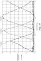
- a diffractive optical element (DOE) in at least one of the in-coupling optical element or the out-coupling light guideis configured to use 7th order diffraction for light including a blue spectral component, 6th order diffraction for light including a green spectral component, and 5th order diffraction for light including a red spectral component.
- DOEdiffractive optical element
- aspectscan include one or more of the following features.
- the display systemfurther comprises: a light pipe configured to couple light between a first DOE in the in-coupling optical element and a second DOE in the out-coupling light guide.
- the display systemfurther comprises: an optical element with an electronically controllable focal distance.
- the optical element with an electronically controllable focal distanceis configured to display multiple images at multiple respective distances sequentially synchronized with the display device.
- Some implementations of the display systems described hereinwork as a periscope with a thin light guide (e.g., a waveguide or light pipe) combined with prisms or Fresnel mirrors having reflective surfaces.
- the display systemsmay be suitable for see-through head-up-displays for automobiles, and can be configured as wearable displays (e.g., as compact as eyeglasses), and can be configured to achieve a wide viewing angle (also referred to as field of view, high resolution, and a large eye-box.
- Some implementationsare capable of increasing the field of view (FOV) of a display using a light guide, such as a waveguide or a light pipe, to pass light from a display to a viewer.
- a light guidesuch as a waveguide or a light pipe
- the angle subtending incoming light into a waveguideremains same if the optical system of the waveguide uses only specular reflection.
- the FOVis identical to the subtending angle of incoming light and the FOV can be increased using a larger angle of converging incoming light into a waveguide, which can be achieved by using more lenses or more complex optical system, for example.
- a holographic optical element (HOE) or diffractive optical element (DOE)will increase the subtending angle of diffracted light when it is used as in-coupling optics, and a HOE or DOE will decrease the subtending angle of diffracted light when it is used as out-coupling optics.
- HOEholographic optical element
- DOEdiffractive optical element
- Some implementations of the systems and devices described hereinuse HOE or DOE for in-coupling optics to increase the subtending angle of diffracted light and use specular reflection for out-coupling, which maintains the subtending angle (e.g., no-increase and no-decrease).
- the resulting combined optics configurationwill expand the subtending angle (d ⁇ i to d ⁇ out) and increase the FOV.
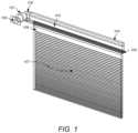
- FIG. 1is a diagram of an example optics system enabling a see-through display forming a virtual image using prism and Fresnel mirrors.
- FIG. 2 Ais a diagram of an example projection lens assembly included as part of in-coupling optics.
- FIG. 2 Bis a diagram of an example of a light guide receiving light from a prism included as part of in-coupling optics.
- FIG. 2 Cis a diagram of an example of a light guide receiving light from a hologram included as part of in-coupling optics.
- FIG. 2 Dis a diagram of an example of a light guide receiving light through a projection lens set and in-coupling optics.
- FIG. 3is a diagram of an example display system.
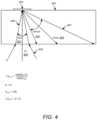
- FIG. 4is a diagram that illustrates how the incident angles of incoming light beams are enlarged by HOE or DOE.
- FIG. 5is a diagram that illustrates why the angle of diffracted light beam is limited by the refractive index of HOE base material.
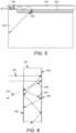
- FIG. 6is a diagram of an example of a light guide with a coating that reflects a light beam whose incident angle is lower than a TIR angle.
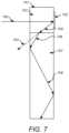
- FIG. 7is a diagram of another example of a light guide.
- FIGS. 8 A, 8 B, and 8 Care diagrams of example structures avoiding unwanted double reflection.
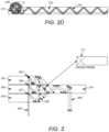
- FIG. 9is a diagram that illustrates how the maximum angle of light beam can be limited by the refractive index of the base material of a HOE.
- FIG. 10is a diagram that illustrates an embodiment of a distortion-free light pipe and light guide system.
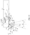
- FIG. 11is a diagram that illustrates another embodiment of distortion-free light pipe and light guide system.
- FIG. 12is a perspective view to show the right path inside a light pipe and a waveguide.
- FIG. 13 Ais a diagram of an example embodiment forming an image at an infinite distance.
- FIG. 13 Bis a diagram of an example embodiment forming an image at an arbitrary distance, which can be electronically controllable.
- FIG. 14is a diagram of an example of a structure of an electronically controllable variable focal distance lens.
- FIGS. 15 A and 15 Bare diagrams of an example embodiment of a very wide angle FOV with 90 degrees (horizontal) ⁇ 90 degrees (vertical) simulated by an optical design tool.
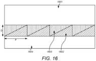
- FIG. 16is a diagram of a structure of a DOE capable of diffracting three primary colors into a same direction with a single layer of a DOE.
- FIG. 17is a plot of the diffraction efficiency vs. a wavelength of incoming light for the DOE shown in FIG. 16 .
- a characteristic of some implementations of a display systemis a relatively large FOV of a see-through display (e.g., over 90 degrees (or +/ ⁇ 45 degrees) horizontally with an eye-box larger than 15 mm).
- An example implementation of a display systemis shown in FIG. 1 .
- a display system 104includes a display device 108 comprising an array of pixels and a set of projection lenses 101 .
- Light rays from the display device 108are projected on a HOE 102 used as in-coupling optics and inputted to a light pipe 103 .
- the light rayspropagate into the light pipe 103 and only the light rays having the same direction as the original rays from the HOE 102 are selected and lead to folding mirrors 105 .
- the light raysare reflected by the folding mirrors 105 about 90 degrees toward an out-coupling light guide 107 .
- the light guide 107is a plate or slab waveguide that guides light between surfaces at interfaces with air or some lower index material by total internal reflection (TIR), and in some implementations the light guide 107 is a plate or slab that guides light reflected between reflective surfaces of the plate or slab.
- TIRtotal internal reflection
- the light raysare reflected toward a viewer's eye by saw-tooth shaped Fresnel mirrors formed on a surface of the light guide 107 . Examples of each element will be explained in more detail below.
- the display systemacts as an exit pupil expander.
- an exit pupil expanderFor example, a viewer should be able to see an image even when he/she moves their eyeballs.
- Some systemsonly have a relatively small exit pupil (e.g., 0.5 mm diameter exit pupil, for example, on the order of a mobile phone's camera lens). But, a human eyeball can move +/ ⁇ half an inch, or a 1-inch range.
- the exit pupil expander functionality of the display system described hereinis able to expand the exit pupil from around a 0.5 mm diameter to around a 1 in (25.4 mm) diameter.
- An in-coupling HOE or DOEcan redirect light beams from an external projector lens system to the inside of a light pipe. Some of the light beams exit from the light pipe through one or more slits or other openings to a Fresnel reflector. The light beams are reflected by an out-coupling element, such as a Fresnel reflector composed of individual reflective grating elements (also referred to herein as “Fresnel mirrors”), toward the outside of the light pipe to enter a light guide. The beams hit a second in-coupling HOE or DOE attached to the light guide and are reflected toward the inside of the light guide.
- an out-coupling elementsuch as a Fresnel reflector composed of individual reflective grating elements (also referred to herein as “Fresnel mirrors”
- the light guideAfter propagating inside the light guide, beams are reflected by out-coupling Fresnel mirrors to an eyeball of a viewer.
- the light guidecan be implemented, for example, as a light guide plate (flat rectangular plate with surfaces of around 50 mm ⁇ 50 mm in size).
- the incoming beam anglecan be compressed (e.g., 60 degrees to 20 degrees).
- the rays of the compressed beampropagate inside the light pipe to be redirected and distributed from multiple openings along the light pipe into the wide area of the light guide plate, allowing a much larger FOV.
- the grating elements of a Fresnel folding mirrorredirect the light to the light guide plate, which expands the exit pupil in a first dimension (e.g., an x-dimension).
- An out-coupling DOEsuch as another Fresnel reflector, attached to the light guide plate also expands the angle of beams exiting to the viewer.
- the out-coupling Fresnel reflectorexpands the exit pupil in a second dimension (e.g., a y-dimension perpendicular to the x-dimension).
- a single DOEis able to diffract three primary color beams into the same direction. This will reduce the number of needed layers of a light guide plate or other out-coupling optics (e.g., from 3 layers to a single layer). Also, images can be formed at each of multiple selected distances dynamically.
- FIGS. 2 A, 2 B, 2 C, and 2 DExample implementations of different kinds of in-coupling optics are shown in FIGS. 2 A, 2 B, 2 C, and 2 D .
- a display device 203provides light to a set of projection lenses 205 , and the distance between the center of the display device 203 and a given pixel (marked as “X” 201 ) is proportional to the projected angle ⁇ 202 of light from that given pixel.
- the projection lenses 205are arranged into a lens assembly that ensures that the angle of an output light ray is proportional to the distance of pixel from the center of the pixel array (or 0 is proportional to X).
- the display device 203emits light beams 204 from each of its pixels to the set of projection lenses 205 .
- This lens set 205is designed as a telecentric optics arrangement meaning that the principal ray of light beams 204 from each pixel of the display device 203 entering the projection lens set 205 is substantially parallel to the optical axis of the projection lens set.
- This lens set 205can be configured such that an image is focused at an infinite or substantially far distance so that all of the rays projected from a single pixel are substantially parallel to each other as shown for light rays 207 A, 207 B, and 207 C in FIG. 2 A .
- This featureis also called an F-Theta lens.
- This optics arrangementensures that all the rays from a single pixel are parallel. This is a principle used in some implementations to focus an image after the rays are mixed in the light pipe, because this optics arrangement ensures that all rays having a same direction are from a single pixel.
- FIG. 2 Bshows an example of a light guide 214 (e.g., a light pipe or a waveguide) having a prism 213 included as part of in-coupling optics receiving light from the display device 211 through a lens set 212 .
- FIG. 2 Cshows an example of a light guide 225 (e.g., a light pipe or a waveguide) having a hologram 221 included as part of in-coupling optics 222 receiving light from the display device 220 through a lens set 223 .
- FIG. 2 Bshows an example of a light guide 214 (e.g., a light pipe or a waveguide) having a prism 213 included as part of in-coupling optics receiving light from the display device 211 through a lens set 212 .
- FIG. 2 Cshows an example of a light guide 225 (e.g., a light pipe or a waveguide) having a hologram 221 included as part of in-coupling optics 222 receiving light from
- FIG. 2 Dshows an example of a light guide 233 (e.g., a light pipe or a waveguide) with a projection lens set 231 providing light to in-coupling optics 232 (e.g., HOE or DOE or prism), showing a light beam 234 propagating inside the light guide 233 .
- a light guide 233e.g., a light pipe or a waveguide
- in-coupling optics 232e.g., HOE or DOE or prism
- FIG. 3Another example implementation is shown in FIG. 3 , in which multiple waveguides 301 , 302 , 303 are integrated into a single waveguide (or layer) 310 using dichroic filters 308 and a cross prism 311 .
- a HOEallows multiple recording and superimposing multiple wavelength holograms into a single layer.
- some types of hologram materialshave a limitation of the maximum number of recording, and a surface relief type DOE does not allow multiple wavelength diffractions. These can use a multi-layer waveguide and often one layer for one color of incoming rays 304 . For a color display, a 3-layer waveguide can be used.
- This example implementationenables a single layer waveguide for multi-color display integrating 3 color layers of a waveguide into a single layer with a dichroic filter 308 and a dichroic cross prism 311 as shown in FIG. 3 .
- Optical element 303is a waveguide for blue and has a HOE or DOE layer at 307 . Light beams diffracted by the HOE or DOE contains 3 colors, but only blue is filtered by the dichroic filter marked as 308 .
- Optical elements 302 and 301are waveguides for green and red respectively. All three color light beams after the filters are lead into the cross prism 311 and integrated into the middle layer 310 for output as reflected rays 309 .
- This integration of 3 layers into a single layeris not limited to waveguide, but also applicable to light pipe.
- FIG. 4Another example implementation is shown in FIG. 4 .
- Incident light raysare shown as (e.g., between ray 405 and ray 406 ) and their subtending angle is shown as d ⁇ i 401 .
- the ray Oi 409is the middle ray between them.
- the incident raysare focused to a HOE or DOE 403 and diffracted by the HOE or DOE 403 to an output angle subtending between ray 402 and ray 407 .
- the angle d ⁇ outis the angle of the middle ray ⁇ out 408 between ray 402 and ray 407 .
- d ⁇ outcos( ⁇ i)*d ⁇ i/cos( ⁇ out)
- ⁇ iis about zero
- ⁇ outis about 120 degrees
- d ⁇ out⁇ 2*d ⁇ i.
- the diffracted beamhas a divergence of angles among its constituent rays that is twice as large as the incident beam.
- the systemcan obtain enlarged output angles from smaller incident angles. This will enlarge the FOV.
- a light pipe 501receives light from an in-coupling optical element 503 (e.g., a HOE or DOE).
- a first expansion direction 504indicates the direction of expansion of beam angles by the in-coupling optical element 503 .
- the diffracted beamshave a distortion of parallelogram toward the expansion direction 504 .
- the openings along the light pipe 501can be locations at which a reflective material is absent, or locations at which an angle of incidence is less than a total internal reflection angle for some of the rays that propagate along the light pipe 501 .
- a second expansion direction 506can be configured to be perpendicular to the expansion direction 504 to minimize the distortion of images.
- the light guidecan be implemented as a waveguide with a high index core surrounded by a lower index cladding (e.g., which could be air in some cases).
- the FOV of a waveguideis limited by the minimum angle of total internal reflection (TIR) of the material used for waveguide core.
- TIRtotal internal reflection
- coatings 605 , 608 on either surface of a transparent slab of materialreflect a light beam whose constituent rays are incident at an angle that is lower than a TIR angle that would be associated with the slab material.
- An in-coupling optic 602is a HOE or a DOE at which the incoming beams 603 are directed. If there were no coatings, the reflected beam 606 would be transmitted as a beam 607 , but with the coating 608 the reflected beam 606 can be reflected as beam 604 .
- FIG. 7Another example implementation of a light guide is shown in FIG. 7 .
- This light guidecomprises two regions made up of two different materials (region 701 and region 707 ), each having a different refractive index.
- This exampleenables a HOE 702 to diffract an incoming beam 700 to a beam 705 that is incident below a TIR angle associated with the material 703 and leads to the region 707 having a higher refractive index and smaller TIR angle to enlarge the FOV.
- the maximum angle of a diffracted beam that is diffracted by the HOE 702is limited due to the refractive index of HOE's base material and it calls for a low or similar refractive index material for a waveguide where HOE is placed.
- a waveguidecan be connected with a higher refractive index material toward an out-coupling region, and the FOV can be increased by this technique.
- a diffracted beam 705would be transmitted (as beam 704 ) if there was not a higher refractive index material in region 707 , but the diffracted beam 705 can be reflected as shown by reflected beams 706 and 708 .
- Example implementations of out-coupling from a light guideare shown in FIGS. 8 A, 8 B, and 8 C .
- unwanted double reflection (or “Ghost image”) of a waveguide having Fresnel mirrorscan be avoided.
- Waveguide material 808has a higher refractive index than the material on either side.
- the waveguideis designed for a single reflection at the flat area 801 or the Fresnel mirror area 802 as shown for incoming rays 803 A, 803 B and reflected rays 804 A, 804 B, and double reflection as shown for an incoming ray 805 to a reflected ray 806 is unwanted.
- FIG. 8 AAnother limiting factor of the FOV is this unwanted reflection by the individual saw-tooth shaped mirrors of the Fresnel reflector of a waveguide as shown in FIG. 8 A .
- beamsmay hit twice (as shown by beams 806 ) before out-coupling from the waveguide, which may not be desired.
- the example of FIG. 8 Bis to laminate a higher refractive index material 808 on waveguide and place Fresnel mirrors on the higher refractive index material 808 .
- FIG. 8 Cshows another example to avoid double reflection with external saw-tooth shaped protrusion of Fresnel mirror grating elements 815 .
- FIG. 9illustrates how the maximum angle ⁇ max of light beam 905 is limited by the refractive index of the base material of a HOE 909 , 910 . If the refractive index of the base material of the HOE is smaller than that of the waveguide 908 , the diffracted beam 904 that is diffracted by the HOE cannot exceed 90 degrees and ⁇ max is limited by the TIR angle between the material of the waveguide 908 and the base material of the HOE 909 .
- the subtending angle d ⁇ out of diffracted light beams 402 and 407 as shown in FIG. 4is substantially larger than incoming beam angle d ⁇ i 401 due to diffraction and the light beams 402 and 407 must be within total internal reflection. This limits the angle of incoming light beams 405 and 406 .
- FIG. 10Another example implementation is shown in FIG. 10 to avoid this potential limitation.
- a structureis shown in FIG. 10 wherein the subtending angle ⁇ in ( ⁇ in 1 + ⁇ in 2 ) of incoming light beams 1007 is reduced by a high refractive index prism 1008 and diffracted by a DOE 1003 , which reduces the angle further, e.g., to ⁇ ′in ( ⁇ ′ ⁇ in 1 + ⁇ ′in 2 ).
- FIG. 11Another example implementation is shown in FIG. 11 .
- the FOVcan be enlarged even further than in the example in FIG. 10 , although a rotational distortion may take place.
- the rotational distortioncan be compensated by rotating the display system.
- FIG. 12Another example display system is shown in FIG. 12 , where half-mirrors are inserted in the light pipe to increase the number of beams keeping the same propagation angles. This will reduce the distance between two beams in the waveguide.
- FIG. 13 ALight beam trajectories are shown in FIG. 13 A for light diffracted from an in-coupling DOE 1305 where the location of images is at an infinite distance because the beams coming from a single pixel are parallel.
- FIG. 13 BAn example is shown in FIG. 13 B wherein the location of images can be electronically controllable using a variable focal length diffractive lens with liquid crystal material electro-statically driven by a driver 1320 to vary its refractive index.
- variable focal length lensAn example of the variable focal length lens is shown in FIG. 14 .
- the refractive index of liquid crystalcan be changed by applying electro-static voltage up to 0.2. However, this is not enough to control the image distance by a refractive lens.
- the diffractive lens shown in FIG. 14can change its focal length enough, because diffraction bends light much more than refraction lens. Multiple images can be displayed sequentially at multiple distances by the single DOE lens with liquid crystal driven voltages. Each image can be synchronized with the focal distance adjusted by the DOE lens.
- person-Ais displayed at 3 m distance at time- 1 and person-B is displayed at 10 m distance at time- 2 and house-A is displayed at 100 m distance at time- 3 and a background scene is displayed at an infinite distance at time- 4 . If these images are switched fast enough, the viewer will not notice the changes and will recognize the resulting combined scene as a virtual and/or augmented reality 3D scene as vergence and accommodation coincide (e.g., not as stereoscopic, but as a so called “light field”).
- FIGS. 15 A and 15 BAn example of super wide FOV augmented reality (AR) display having 90° (horizontal) ⁇ 90° (vertical) was successfully designed and simulated with a optical design tool and shown in FIGS. 15 A and 15 B .
- ARaugmented reality
- ⁇ inthe angle of incoming light to the normal direction of DOE surface
- the outgoing anglewill differ depending of the incoming light's wavelength. This is the reason why a single DOE may in some cases not be used for different colors, and multi-plate or multi-layer DOE may be used to provide a color display.
Landscapes
- Physics & Mathematics (AREA)
- General Physics & Mathematics (AREA)
- Optics & Photonics (AREA)
- Diffracting Gratings Or Hologram Optical Elements (AREA)
Abstract
Description
sin(θout)−sin(θin)=m/λ*constant(function of pitch of grooves, such as the saw-tooth shaped mirrors)
Claims (25)
Priority Applications (3)
| Application Number | Priority Date | Filing Date | Title |
|---|---|---|---|
| US16/934,536US11656458B2 (en) | 2019-01-23 | 2020-07-21 | Optics of a display using an optical light guide |
| CN202110065188.8ACN113138462A (en) | 2020-01-17 | 2021-01-18 | Display optics using light guides |
| JP2021007529AJP2021119378A (en) | 2020-01-17 | 2021-01-20 | Optical system of display using optical light guide |
Applications Claiming Priority (4)
| Application Number | Priority Date | Filing Date | Title |
|---|---|---|---|
| US16/255,799US11422371B2 (en) | 2018-06-30 | 2019-01-23 | Augmented reality (AR) display |
| US202062962566P | 2020-01-17 | 2020-01-17 | |
| US202063019388P | 2020-05-03 | 2020-05-03 | |
| US16/934,536US11656458B2 (en) | 2019-01-23 | 2020-07-21 | Optics of a display using an optical light guide |
Related Parent Applications (1)
| Application Number | Title | Priority Date | Filing Date |
|---|---|---|---|
| US16/255,799Continuation-In-PartUS11422371B2 (en) | 2018-06-30 | 2019-01-23 | Augmented reality (AR) display |
Publications (2)
| Publication Number | Publication Date |
|---|---|
| US20210026135A1 US20210026135A1 (en) | 2021-01-28 |
| US11656458B2true US11656458B2 (en) | 2023-05-23 |
Family
ID=74190079
Family Applications (1)
| Application Number | Title | Priority Date | Filing Date |
|---|---|---|---|
| US16/934,536Active2039-03-09US11656458B2 (en) | 2019-01-23 | 2020-07-21 | Optics of a display using an optical light guide |
Country Status (3)
| Country | Link |
|---|---|
| US (1) | US11656458B2 (en) |
| JP (1) | JP2021119378A (en) |
| CN (1) | CN113138462A (en) |
Families Citing this family (9)
| Publication number | Priority date | Publication date | Assignee | Title |
|---|---|---|---|---|
| GB2588470B (en)* | 2020-02-19 | 2022-01-12 | Envisics Ltd | Pupil expansion |
| CN112987302B (en)* | 2021-02-05 | 2022-10-18 | 业成科技(成都)有限公司 | Head-mounted display device and display system thereof |
| KR20240005001A (en)* | 2021-05-07 | 2024-01-11 | 어플라이드 머티어리얼스, 인코포레이티드 | Waveguide couplers with pass-through in-coupler grating |
| CN114415376B (en)* | 2022-01-26 | 2023-10-17 | 武汉华星光电技术有限公司 | Display device and virtual reality display device |
| GB2616305B (en)* | 2022-03-04 | 2025-02-05 | Envisics Ltd | Hologram calculation |
| CN114859554B (en)* | 2022-04-02 | 2023-06-13 | 江西凤凰光学科技有限公司 | A multi-layer diffractive optical waveguide device |
| GB2620128B (en)* | 2022-06-28 | 2025-01-15 | Envisics Ltd | Compact head-up display and pupil expander therefor |
| US20240168284A1 (en)* | 2022-11-17 | 2024-05-23 | Meta Platforms Technologies, Llc | Holographic vr display |
| US20240393590A1 (en)* | 2023-05-23 | 2024-11-28 | National Central University | Diffractive optical assembly and head-mounted display having the same |
Citations (42)
| Publication number | Priority date | Publication date | Assignee | Title |
|---|---|---|---|---|
| WO1999052002A1 (en) | 1998-04-02 | 1999-10-14 | Elop Electro-Optics Industries Ltd. | Holographic optical devices |
| US6115151A (en) | 1998-12-30 | 2000-09-05 | Digilens, Inc. | Method for producing a multi-layer holographic device |
| US20010050758A1 (en)* | 2000-05-10 | 2001-12-13 | Hiroshi Suzuki | Image display device and adjustment for alignment |
| US20040085649A1 (en)* | 2002-07-17 | 2004-05-06 | C.R.F. Societa Consortile Per Azioni | Light guide for display devices of the head-mounted or head-up type |
| US6805490B2 (en) | 2002-09-30 | 2004-10-19 | Nokia Corporation | Method and system for beam expansion in a display device |
| US7181108B2 (en) | 2003-05-13 | 2007-02-20 | Nokia Corporation | Method and optical system for coupling light into a waveguide |
| US7184615B2 (en) | 2002-09-19 | 2007-02-27 | Nokia Corporation | Electrically tunable diffractive grating element |
| US20090296049A1 (en)* | 2008-05-30 | 2009-12-03 | Chinontec Industries, Inc. | Projection display device |
| US7764413B2 (en) | 2004-12-13 | 2010-07-27 | Nokia Corporation | General diffractive optics method for expanding an exit pupil |
| US7885506B2 (en) | 2008-09-26 | 2011-02-08 | Nokia Corporation | Device and a method for polarized illumination of a micro-display |
| US8155489B2 (en) | 2006-11-02 | 2012-04-10 | Nokia Corporation | Method for coupling light into a thin planar waveguide |
| US8160411B2 (en) | 2006-12-28 | 2012-04-17 | Nokia Corporation | Device for expanding an exit pupil in two dimensions |
| US8314993B2 (en) | 2006-06-02 | 2012-11-20 | Nokia Corporation | Split exit pupil expander |
| US8320032B2 (en) | 2007-06-04 | 2012-11-27 | Nokia Corporation | Diffractive beam expander and a virtual display based on a diffractive beam expander |
| US20130128611A1 (en)* | 2011-11-22 | 2013-05-23 | Sony Corporation | Light beam expanding device, image display device, and optical device |
| US20140204185A1 (en)* | 2011-08-24 | 2014-07-24 | Zhejiang University | Multi-pitching angle suspended 3d display device with 360-degree field of view |
| US20150016777A1 (en) | 2012-06-11 | 2015-01-15 | Magic Leap, Inc. | Planar waveguide apparatus with diffraction element(s) and system employing same |
| US9304235B2 (en) | 2014-07-30 | 2016-04-05 | Microsoft Technology Licensing, Llc | Microfabrication |
| US20160327789A1 (en) | 2013-11-27 | 2016-11-10 | Magic Leap, Inc. | Separated pupil optical systems for virtual and augmented reality and methods for displaying images using same |
| US9513480B2 (en) | 2015-02-09 | 2016-12-06 | Microsoft Technology Licensing, Llc | Waveguide |
| US20170045743A1 (en)* | 2014-04-17 | 2017-02-16 | Carl Zeiss Smart Optics Gmbh | Spectacle lens for a display device that can be fitted on the head of a user and generates an image, and display device with such a spectacle lens |
| US9625717B2 (en) | 2012-09-20 | 2017-04-18 | Dispelix Oy | Optical device with diffractive grating |
| US20170204185A1 (en)* | 2000-07-27 | 2017-07-20 | Mayo Foundation For Medical Education And Research | B7-h3 and b7-h4, novel immunoregulatory molecules |
| US20170293143A1 (en)* | 2016-04-07 | 2017-10-12 | Google Inc. | Curved eyepiece with color correction for head wearable display |
| US20180003994A1 (en) | 2015-01-16 | 2018-01-04 | Wave Optics Ltd. | Display system |
| US20180052277A1 (en) | 2016-08-22 | 2018-02-22 | Magic Leap, Inc. | Multi-layer diffractive eyepiece |
| US9910276B2 (en) | 2015-06-30 | 2018-03-06 | Microsoft Technology Licensing, Llc | Diffractive optical elements with graded edges |
| US20180067318A1 (en) | 2016-09-07 | 2018-03-08 | Magic Leap, Inc. | Virtual reality, augmented reality, and mixed reality systems including thick media and related methods |
| US10018844B2 (en) | 2015-02-09 | 2018-07-10 | Microsoft Technology Licensing, Llc | Wearable image display system |
| US20180217305A1 (en) | 2015-06-10 | 2018-08-02 | Wave Optics Ltd | Optical display device |
| US20180292651A1 (en) | 2016-09-07 | 2018-10-11 | Jeong Hun Ha | Reflective lens module |
| US10114220B2 (en) | 2014-08-03 | 2018-10-30 | Wave Optics Ltd | Exit pupil expanding diffractive optical waveguiding device |
| US10156725B2 (en) | 2014-09-29 | 2018-12-18 | Magic Leap, Inc. | Architectures and methods for outputting different wavelength light out of waveguides |
| US20190086668A1 (en) | 2016-03-18 | 2019-03-21 | Letinar Co., Ltd | Apparatus equipped with depth control function for enabling augmented reality |
| US10317677B2 (en) | 2015-02-09 | 2019-06-11 | Microsoft Technology Licensing, Llc | Display system |
| US20190204600A1 (en) | 2017-12-29 | 2019-07-04 | Letinar Co., Ltd. | Augmented reality optics system with pinpoint mirror |
| US10359627B2 (en) | 2015-11-10 | 2019-07-23 | Microsoft Technology Licensing, Llc | Waveguide coatings or substrates to improve intensity distributions having adjacent planar optical component separate from an input, output, or intermediate coupler |
| US10379358B2 (en) | 2015-04-08 | 2019-08-13 | Despelix Oy | Optical see-through display element and device utilizing such element |
| US10459145B2 (en) | 2015-03-16 | 2019-10-29 | Digilens Inc. | Waveguide device incorporating a light pipe |
| US10509241B1 (en) | 2009-09-30 | 2019-12-17 | Rockwell Collins, Inc. | Optical displays |
| US10545346B2 (en) | 2017-01-05 | 2020-01-28 | Digilens Inc. | Wearable heads up displays |
| US20200259307A1 (en)* | 2019-02-08 | 2020-08-13 | Facebook Technologies, Llc | Optical elements for beam-shaping and illumination |
Family Cites Families (17)
| Publication number | Priority date | Publication date | Assignee | Title |
|---|---|---|---|---|
| JP2000081573A (en)* | 1998-06-30 | 2000-03-21 | Olympus Optical Co Ltd | Optical system and image pickup device |
| US7418170B2 (en)* | 2004-03-29 | 2008-08-26 | Sony Corporation | Optical device and virtual image display device |
| US9188731B2 (en)* | 2012-05-18 | 2015-11-17 | Reald Inc. | Directional backlight |
| JP6246231B2 (en)* | 2013-11-25 | 2017-12-13 | シャープ株式会社 | Light guide and head mounted display |
| JP2016085430A (en)* | 2014-10-29 | 2016-05-19 | セイコーエプソン株式会社 | Virtual image display device |
| IL310369A (en)* | 2015-01-26 | 2024-03-01 | Magic Leap Inc | Virtual and augmented reality systems and methods with improved diffractive lattice structures |
| JP6565496B2 (en)* | 2015-08-31 | 2019-08-28 | セイコーエプソン株式会社 | Light guide device and virtual image display device |
| DE102015122131B3 (en)* | 2015-12-17 | 2017-03-02 | Carl Zeiss Smart Optics Gmbh | Spectacle lens for a display device which can be placed on the head of a user and generates an image, and a display device with such a spectacle lens |
| KR102805976B1 (en)* | 2016-10-28 | 2025-05-09 | 매직 립, 인코포레이티드 | Method and system for large field of view display with scanning reflector |
| CN108873327B (en)* | 2017-05-16 | 2021-03-05 | 中强光电股份有限公司 | Head-mounted display device |
| KR20180106624A (en)* | 2017-03-21 | 2018-10-01 | 주식회사 파노비젼 | Optic system of see-through head mounted display having expanding manners for horizontal and vertical exit pupils |
| WO2019016926A1 (en)* | 2017-07-20 | 2019-01-24 | サン電子株式会社 | Head-mounted display apparatus |
| JP2019066813A (en)* | 2017-09-28 | 2019-04-25 | セイコーエプソン株式会社 | Light guide device and display device |
| JP7200637B2 (en)* | 2017-12-25 | 2023-01-10 | 株式会社リコー | Head-mounted display and display system |
| JP6939669B2 (en)* | 2018-03-20 | 2021-09-22 | セイコーエプソン株式会社 | Virtual image display device |
| JP7230072B2 (en)* | 2018-06-30 | 2023-02-28 | フサオ イシイ | display system |
| JP6778405B2 (en)* | 2019-08-09 | 2020-11-04 | 株式会社リコー | Light guide member, light guide and virtual image display device |
- 2020
- 2020-07-21USUS16/934,536patent/US11656458B2/enactiveActive
- 2021
- 2021-01-18CNCN202110065188.8Apatent/CN113138462A/enactivePending
- 2021-01-20JPJP2021007529Apatent/JP2021119378A/enactivePending
Patent Citations (46)
| Publication number | Priority date | Publication date | Assignee | Title |
|---|---|---|---|---|
| WO1999052002A1 (en) | 1998-04-02 | 1999-10-14 | Elop Electro-Optics Industries Ltd. | Holographic optical devices |
| US6115151A (en) | 1998-12-30 | 2000-09-05 | Digilens, Inc. | Method for producing a multi-layer holographic device |
| US20010050758A1 (en)* | 2000-05-10 | 2001-12-13 | Hiroshi Suzuki | Image display device and adjustment for alignment |
| US20170204185A1 (en)* | 2000-07-27 | 2017-07-20 | Mayo Foundation For Medical Education And Research | B7-h3 and b7-h4, novel immunoregulatory molecules |
| US20040085649A1 (en)* | 2002-07-17 | 2004-05-06 | C.R.F. Societa Consortile Per Azioni | Light guide for display devices of the head-mounted or head-up type |
| US7184615B2 (en) | 2002-09-19 | 2007-02-27 | Nokia Corporation | Electrically tunable diffractive grating element |
| US6805490B2 (en) | 2002-09-30 | 2004-10-19 | Nokia Corporation | Method and system for beam expansion in a display device |
| US7181108B2 (en) | 2003-05-13 | 2007-02-20 | Nokia Corporation | Method and optical system for coupling light into a waveguide |
| US7764413B2 (en) | 2004-12-13 | 2010-07-27 | Nokia Corporation | General diffractive optics method for expanding an exit pupil |
| US8314993B2 (en) | 2006-06-02 | 2012-11-20 | Nokia Corporation | Split exit pupil expander |
| US8155489B2 (en) | 2006-11-02 | 2012-04-10 | Nokia Corporation | Method for coupling light into a thin planar waveguide |
| US8160411B2 (en) | 2006-12-28 | 2012-04-17 | Nokia Corporation | Device for expanding an exit pupil in two dimensions |
| US8320032B2 (en) | 2007-06-04 | 2012-11-27 | Nokia Corporation | Diffractive beam expander and a virtual display based on a diffractive beam expander |
| US20090296049A1 (en)* | 2008-05-30 | 2009-12-03 | Chinontec Industries, Inc. | Projection display device |
| US7885506B2 (en) | 2008-09-26 | 2011-02-08 | Nokia Corporation | Device and a method for polarized illumination of a micro-display |
| US10509241B1 (en) | 2009-09-30 | 2019-12-17 | Rockwell Collins, Inc. | Optical displays |
| US20140204185A1 (en)* | 2011-08-24 | 2014-07-24 | Zhejiang University | Multi-pitching angle suspended 3d display device with 360-degree field of view |
| US20130128611A1 (en)* | 2011-11-22 | 2013-05-23 | Sony Corporation | Light beam expanding device, image display device, and optical device |
| US20150016777A1 (en) | 2012-06-11 | 2015-01-15 | Magic Leap, Inc. | Planar waveguide apparatus with diffraction element(s) and system employing same |
| US9625717B2 (en) | 2012-09-20 | 2017-04-18 | Dispelix Oy | Optical device with diffractive grating |
| US20160327789A1 (en) | 2013-11-27 | 2016-11-10 | Magic Leap, Inc. | Separated pupil optical systems for virtual and augmented reality and methods for displaying images using same |
| US20170045743A1 (en)* | 2014-04-17 | 2017-02-16 | Carl Zeiss Smart Optics Gmbh | Spectacle lens for a display device that can be fitted on the head of a user and generates an image, and display device with such a spectacle lens |
| US9304235B2 (en) | 2014-07-30 | 2016-04-05 | Microsoft Technology Licensing, Llc | Microfabrication |
| US10114220B2 (en) | 2014-08-03 | 2018-10-30 | Wave Optics Ltd | Exit pupil expanding diffractive optical waveguiding device |
| US10359635B2 (en) | 2014-08-03 | 2019-07-23 | Wave Optics Ltd. | Exit pupil expanding diffractive optical waveguiding device |
| US10261318B2 (en) | 2014-09-29 | 2019-04-16 | Magic Leap, Inc. | Architectures and methods for outputting different wavelength light out of waveguides |
| US10156725B2 (en) | 2014-09-29 | 2018-12-18 | Magic Leap, Inc. | Architectures and methods for outputting different wavelength light out of waveguides |
| US20180003994A1 (en) | 2015-01-16 | 2018-01-04 | Wave Optics Ltd. | Display system |
| US10317677B2 (en) | 2015-02-09 | 2019-06-11 | Microsoft Technology Licensing, Llc | Display system |
| US10345601B2 (en) | 2015-02-09 | 2019-07-09 | Microsoft Technology Licensing, Llc | Wearable image display system |
| US9513480B2 (en) | 2015-02-09 | 2016-12-06 | Microsoft Technology Licensing, Llc | Waveguide |
| US10018844B2 (en) | 2015-02-09 | 2018-07-10 | Microsoft Technology Licensing, Llc | Wearable image display system |
| US10459145B2 (en) | 2015-03-16 | 2019-10-29 | Digilens Inc. | Waveguide device incorporating a light pipe |
| US10379358B2 (en) | 2015-04-08 | 2019-08-13 | Despelix Oy | Optical see-through display element and device utilizing such element |
| US20180217305A1 (en) | 2015-06-10 | 2018-08-02 | Wave Optics Ltd | Optical display device |
| US9910276B2 (en) | 2015-06-30 | 2018-03-06 | Microsoft Technology Licensing, Llc | Diffractive optical elements with graded edges |
| US10359627B2 (en) | 2015-11-10 | 2019-07-23 | Microsoft Technology Licensing, Llc | Waveguide coatings or substrates to improve intensity distributions having adjacent planar optical component separate from an input, output, or intermediate coupler |
| US20190086668A1 (en) | 2016-03-18 | 2019-03-21 | Letinar Co., Ltd | Apparatus equipped with depth control function for enabling augmented reality |
| US20170293143A1 (en)* | 2016-04-07 | 2017-10-12 | Google Inc. | Curved eyepiece with color correction for head wearable display |
| US20180052277A1 (en) | 2016-08-22 | 2018-02-22 | Magic Leap, Inc. | Multi-layer diffractive eyepiece |
| US20180059304A1 (en) | 2016-08-22 | 2018-03-01 | Magic Leap, Inc. | Dithering methods and apparatus for wearable display device |
| US20180067318A1 (en) | 2016-09-07 | 2018-03-08 | Magic Leap, Inc. | Virtual reality, augmented reality, and mixed reality systems including thick media and related methods |
| US20180292651A1 (en) | 2016-09-07 | 2018-10-11 | Jeong Hun Ha | Reflective lens module |
| US10545346B2 (en) | 2017-01-05 | 2020-01-28 | Digilens Inc. | Wearable heads up displays |
| US20190204600A1 (en) | 2017-12-29 | 2019-07-04 | Letinar Co., Ltd. | Augmented reality optics system with pinpoint mirror |
| US20200259307A1 (en)* | 2019-02-08 | 2020-08-13 | Facebook Technologies, Llc | Optical elements for beam-shaping and illumination |
Also Published As
| Publication number | Publication date |
|---|---|
| US20210026135A1 (en) | 2021-01-28 |
| JP2021119378A (en) | 2021-08-12 |
| CN113138462A (en) | 2021-07-20 |
Similar Documents
| Publication | Publication Date | Title |
|---|---|---|
| US11656458B2 (en) | Optics of a display using an optical light guide | |
| US20240077734A1 (en) | Highly efficient compact head-mounted display system | |
| US11256100B2 (en) | Head-mounted display with pivoting imaging light guide | |
| AU2001256644B2 (en) | Substrate-guided optical beam expander | |
| EP1952189B1 (en) | Display with image-guiding substrate | |
| US5418584A (en) | Retroreflective array virtual image projection screen | |
| US11598970B2 (en) | Imaging light guide with reflective turning array | |
| US7101048B2 (en) | Flat-panel projection display | |
| AU2001256644A1 (en) | Substrate-guided optical beam expander | |
| US11194158B2 (en) | Light guide with beam separator for dual images | |
| JP7230072B2 (en) | display system | |
| WO2017223167A1 (en) | Optics of wearable display devices | |
| CN119856098A (en) | Deformation directional lighting device | |
| CN116774453A (en) | Method and system for RGB luminaire | |
| US20250102803A1 (en) | Image light guide with interference filter | |
| EP4508472A1 (en) | Dual index waveguide stack | |
| US20240427161A1 (en) | Anamorphic directional illumination device | |
| US20240427152A1 (en) | Anamorphic directional illumination device | |
| ZA200400950B (en) | Flat-panel projection display. | |
| HK1057613B (en) | Substrate-guided optical beam expander |
Legal Events
| Date | Code | Title | Description |
|---|---|---|---|
| FEPP | Fee payment procedure | Free format text:ENTITY STATUS SET TO UNDISCOUNTED (ORIGINAL EVENT CODE: BIG.); ENTITY STATUS OF PATENT OWNER: LARGE ENTITY | |
| AS | Assignment | Owner name:ISHII, FUSAO, PENNSYLVANIA Free format text:ASSIGNMENT OF ASSIGNORS INTEREST;ASSIGNORS:NAKANISHI, MIKIKO;ICHIKAWA, KAZUOKI;IWAMURA, MIKIO;REEL/FRAME:053427/0139 Effective date:20200701 Owner name:NTT DOCOMO, INC., JAPAN Free format text:ASSIGNMENT OF ASSIGNORS INTEREST;ASSIGNORS:NAKANISHI, MIKIKO;ICHIKAWA, KAZUOKI;IWAMURA, MIKIO;REEL/FRAME:053427/0139 Effective date:20200701 | |
| STPP | Information on status: patent application and granting procedure in general | Free format text:APPLICATION DISPATCHED FROM PREEXAM, NOT YET DOCKETED | |
| STPP | Information on status: patent application and granting procedure in general | Free format text:DOCKETED NEW CASE - READY FOR EXAMINATION | |
| STPP | Information on status: patent application and granting procedure in general | Free format text:NON FINAL ACTION MAILED | |
| STPP | Information on status: patent application and granting procedure in general | Free format text:RESPONSE TO NON-FINAL OFFICE ACTION ENTERED AND FORWARDED TO EXAMINER | |
| STPP | Information on status: patent application and granting procedure in general | Free format text:FINAL REJECTION MAILED | |
| STPP | Information on status: patent application and granting procedure in general | Free format text:RESPONSE AFTER FINAL ACTION FORWARDED TO EXAMINER | |
| STCF | Information on status: patent grant | Free format text:PATENTED CASE |