US11656003B2 - Climate-control system having valve assembly - Google Patents
Climate-control system having valve assemblyDownload PDFInfo
- Publication number
- US11656003B2 US11656003B2US16/814,487US202016814487AUS11656003B2US 11656003 B2US11656003 B2US 11656003B2US 202016814487 AUS202016814487 AUS 202016814487AUS 11656003 B2US11656003 B2US 11656003B2
- Authority
- US
- United States
- Prior art keywords
- fluid
- fitting
- suction chamber
- compressor
- injection
- Prior art date
- Legal status (The legal status is an assumption and is not a legal conclusion. Google has not performed a legal analysis and makes no representation as to the accuracy of the status listed.)
- Active, expires
Links
Images


Classifications
- F—MECHANICAL ENGINEERING; LIGHTING; HEATING; WEAPONS; BLASTING
- F25—REFRIGERATION OR COOLING; COMBINED HEATING AND REFRIGERATION SYSTEMS; HEAT PUMP SYSTEMS; MANUFACTURE OR STORAGE OF ICE; LIQUEFACTION SOLIDIFICATION OF GASES
- F25B—REFRIGERATION MACHINES, PLANTS OR SYSTEMS; COMBINED HEATING AND REFRIGERATION SYSTEMS; HEAT PUMP SYSTEMS
- F25B1/00—Compression machines, plants or systems with non-reversible cycle
- F25B1/04—Compression machines, plants or systems with non-reversible cycle with compressor of rotary type
- F—MECHANICAL ENGINEERING; LIGHTING; HEATING; WEAPONS; BLASTING
- F04—POSITIVE - DISPLACEMENT MACHINES FOR LIQUIDS; PUMPS FOR LIQUIDS OR ELASTIC FLUIDS
- F04C—ROTARY-PISTON, OR OSCILLATING-PISTON, POSITIVE-DISPLACEMENT MACHINES FOR LIQUIDS; ROTARY-PISTON, OR OSCILLATING-PISTON, POSITIVE-DISPLACEMENT PUMPS
- F04C14/00—Control of, monitoring of, or safety arrangements for, machines, pumps or pumping installations
- F04C14/24—Control of, monitoring of, or safety arrangements for, machines, pumps or pumping installations characterised by using valves controlling pressure or flow rate, e.g. discharge valves or unloading valves
- F04C14/26—Control of, monitoring of, or safety arrangements for, machines, pumps or pumping installations characterised by using valves controlling pressure or flow rate, e.g. discharge valves or unloading valves using bypass channels
- F—MECHANICAL ENGINEERING; LIGHTING; HEATING; WEAPONS; BLASTING
- F04—POSITIVE - DISPLACEMENT MACHINES FOR LIQUIDS; PUMPS FOR LIQUIDS OR ELASTIC FLUIDS
- F04C—ROTARY-PISTON, OR OSCILLATING-PISTON, POSITIVE-DISPLACEMENT MACHINES FOR LIQUIDS; ROTARY-PISTON, OR OSCILLATING-PISTON, POSITIVE-DISPLACEMENT PUMPS
- F04C18/00—Rotary-piston pumps specially adapted for elastic fluids
- F04C18/02—Rotary-piston pumps specially adapted for elastic fluids of arcuate-engagement type, i.e. with circular translatory movement of co-operating members, each member having the same number of teeth or tooth-equivalents
- F04C18/0207—Rotary-piston pumps specially adapted for elastic fluids of arcuate-engagement type, i.e. with circular translatory movement of co-operating members, each member having the same number of teeth or tooth-equivalents both members having co-operating elements in spiral form
- F04C18/0215—Rotary-piston pumps specially adapted for elastic fluids of arcuate-engagement type, i.e. with circular translatory movement of co-operating members, each member having the same number of teeth or tooth-equivalents both members having co-operating elements in spiral form where only one member is moving
- F—MECHANICAL ENGINEERING; LIGHTING; HEATING; WEAPONS; BLASTING
- F04—POSITIVE - DISPLACEMENT MACHINES FOR LIQUIDS; PUMPS FOR LIQUIDS OR ELASTIC FLUIDS
- F04C—ROTARY-PISTON, OR OSCILLATING-PISTON, POSITIVE-DISPLACEMENT MACHINES FOR LIQUIDS; ROTARY-PISTON, OR OSCILLATING-PISTON, POSITIVE-DISPLACEMENT PUMPS
- F04C18/00—Rotary-piston pumps specially adapted for elastic fluids
- F04C18/02—Rotary-piston pumps specially adapted for elastic fluids of arcuate-engagement type, i.e. with circular translatory movement of co-operating members, each member having the same number of teeth or tooth-equivalents
- F04C18/0207—Rotary-piston pumps specially adapted for elastic fluids of arcuate-engagement type, i.e. with circular translatory movement of co-operating members, each member having the same number of teeth or tooth-equivalents both members having co-operating elements in spiral form
- F04C18/0246—Details concerning the involute wraps or their base, e.g. geometry
- F04C18/0253—Details concerning the base
- F—MECHANICAL ENGINEERING; LIGHTING; HEATING; WEAPONS; BLASTING
- F04—POSITIVE - DISPLACEMENT MACHINES FOR LIQUIDS; PUMPS FOR LIQUIDS OR ELASTIC FLUIDS
- F04C—ROTARY-PISTON, OR OSCILLATING-PISTON, POSITIVE-DISPLACEMENT MACHINES FOR LIQUIDS; ROTARY-PISTON, OR OSCILLATING-PISTON, POSITIVE-DISPLACEMENT PUMPS
- F04C18/00—Rotary-piston pumps specially adapted for elastic fluids
- F04C18/02—Rotary-piston pumps specially adapted for elastic fluids of arcuate-engagement type, i.e. with circular translatory movement of co-operating members, each member having the same number of teeth or tooth-equivalents
- F04C18/0207—Rotary-piston pumps specially adapted for elastic fluids of arcuate-engagement type, i.e. with circular translatory movement of co-operating members, each member having the same number of teeth or tooth-equivalents both members having co-operating elements in spiral form
- F04C18/0246—Details concerning the involute wraps or their base, e.g. geometry
- F04C18/0269—Details concerning the involute wraps
- F—MECHANICAL ENGINEERING; LIGHTING; HEATING; WEAPONS; BLASTING
- F04—POSITIVE - DISPLACEMENT MACHINES FOR LIQUIDS; PUMPS FOR LIQUIDS OR ELASTIC FLUIDS
- F04C—ROTARY-PISTON, OR OSCILLATING-PISTON, POSITIVE-DISPLACEMENT MACHINES FOR LIQUIDS; ROTARY-PISTON, OR OSCILLATING-PISTON, POSITIVE-DISPLACEMENT PUMPS
- F04C23/00—Combinations of two or more pumps, each being of rotary-piston or oscillating-piston type, specially adapted for elastic fluids; Pumping installations specially adapted for elastic fluids; Multi-stage pumps specially adapted for elastic fluids
- F04C23/008—Hermetic pumps
- F—MECHANICAL ENGINEERING; LIGHTING; HEATING; WEAPONS; BLASTING
- F04—POSITIVE - DISPLACEMENT MACHINES FOR LIQUIDS; PUMPS FOR LIQUIDS OR ELASTIC FLUIDS
- F04C—ROTARY-PISTON, OR OSCILLATING-PISTON, POSITIVE-DISPLACEMENT MACHINES FOR LIQUIDS; ROTARY-PISTON, OR OSCILLATING-PISTON, POSITIVE-DISPLACEMENT PUMPS
- F04C28/00—Control of, monitoring of, or safety arrangements for, pumps or pumping installations specially adapted for elastic fluids
- F04C28/24—Control of, monitoring of, or safety arrangements for, pumps or pumping installations specially adapted for elastic fluids characterised by using valves controlling pressure or flow rate, e.g. discharge valves or unloading valves
- F—MECHANICAL ENGINEERING; LIGHTING; HEATING; WEAPONS; BLASTING
- F04—POSITIVE - DISPLACEMENT MACHINES FOR LIQUIDS; PUMPS FOR LIQUIDS OR ELASTIC FLUIDS
- F04C—ROTARY-PISTON, OR OSCILLATING-PISTON, POSITIVE-DISPLACEMENT MACHINES FOR LIQUIDS; ROTARY-PISTON, OR OSCILLATING-PISTON, POSITIVE-DISPLACEMENT PUMPS
- F04C28/00—Control of, monitoring of, or safety arrangements for, pumps or pumping installations specially adapted for elastic fluids
- F04C28/28—Safety arrangements; Monitoring
- F—MECHANICAL ENGINEERING; LIGHTING; HEATING; WEAPONS; BLASTING
- F04—POSITIVE - DISPLACEMENT MACHINES FOR LIQUIDS; PUMPS FOR LIQUIDS OR ELASTIC FLUIDS
- F04C—ROTARY-PISTON, OR OSCILLATING-PISTON, POSITIVE-DISPLACEMENT MACHINES FOR LIQUIDS; ROTARY-PISTON, OR OSCILLATING-PISTON, POSITIVE-DISPLACEMENT PUMPS
- F04C29/00—Component parts, details or accessories of pumps or pumping installations, not provided for in groups F04C18/00 - F04C28/00
- F04C29/0007—Injection of a fluid in the working chamber for sealing, cooling and lubricating
- F—MECHANICAL ENGINEERING; LIGHTING; HEATING; WEAPONS; BLASTING
- F04—POSITIVE - DISPLACEMENT MACHINES FOR LIQUIDS; PUMPS FOR LIQUIDS OR ELASTIC FLUIDS
- F04C—ROTARY-PISTON, OR OSCILLATING-PISTON, POSITIVE-DISPLACEMENT MACHINES FOR LIQUIDS; ROTARY-PISTON, OR OSCILLATING-PISTON, POSITIVE-DISPLACEMENT PUMPS
- F04C29/00—Component parts, details or accessories of pumps or pumping installations, not provided for in groups F04C18/00 - F04C28/00
- F04C29/04—Heating; Cooling; Heat insulation
- F—MECHANICAL ENGINEERING; LIGHTING; HEATING; WEAPONS; BLASTING
- F04—POSITIVE - DISPLACEMENT MACHINES FOR LIQUIDS; PUMPS FOR LIQUIDS OR ELASTIC FLUIDS
- F04C—ROTARY-PISTON, OR OSCILLATING-PISTON, POSITIVE-DISPLACEMENT MACHINES FOR LIQUIDS; ROTARY-PISTON, OR OSCILLATING-PISTON, POSITIVE-DISPLACEMENT PUMPS
- F04C29/00—Component parts, details or accessories of pumps or pumping installations, not provided for in groups F04C18/00 - F04C28/00
- F04C29/12—Arrangements for admission or discharge of the working fluid, e.g. constructional features of the inlet or outlet
- F04C29/124—Arrangements for admission or discharge of the working fluid, e.g. constructional features of the inlet or outlet with inlet and outlet valves specially adapted for rotary or oscillating piston pumps
- F—MECHANICAL ENGINEERING; LIGHTING; HEATING; WEAPONS; BLASTING
- F25—REFRIGERATION OR COOLING; COMBINED HEATING AND REFRIGERATION SYSTEMS; HEAT PUMP SYSTEMS; MANUFACTURE OR STORAGE OF ICE; LIQUEFACTION SOLIDIFICATION OF GASES
- F25B—REFRIGERATION MACHINES, PLANTS OR SYSTEMS; COMBINED HEATING AND REFRIGERATION SYSTEMS; HEAT PUMP SYSTEMS
- F25B31/00—Compressor arrangements
- F25B31/02—Compressor arrangements of motor-compressor units
- F25B31/026—Compressor arrangements of motor-compressor units with compressor of rotary type
- F—MECHANICAL ENGINEERING; LIGHTING; HEATING; WEAPONS; BLASTING
- F25—REFRIGERATION OR COOLING; COMBINED HEATING AND REFRIGERATION SYSTEMS; HEAT PUMP SYSTEMS; MANUFACTURE OR STORAGE OF ICE; LIQUEFACTION SOLIDIFICATION OF GASES
- F25B—REFRIGERATION MACHINES, PLANTS OR SYSTEMS; COMBINED HEATING AND REFRIGERATION SYSTEMS; HEAT PUMP SYSTEMS
- F25B41/00—Fluid-circulation arrangements
- F25B41/20—Disposition of valves, e.g. of on-off valves or flow control valves
- F—MECHANICAL ENGINEERING; LIGHTING; HEATING; WEAPONS; BLASTING
- F25—REFRIGERATION OR COOLING; COMBINED HEATING AND REFRIGERATION SYSTEMS; HEAT PUMP SYSTEMS; MANUFACTURE OR STORAGE OF ICE; LIQUEFACTION SOLIDIFICATION OF GASES
- F25B—REFRIGERATION MACHINES, PLANTS OR SYSTEMS; COMBINED HEATING AND REFRIGERATION SYSTEMS; HEAT PUMP SYSTEMS
- F25B2400/00—General features or devices for refrigeration machines, plants or systems, combined heating and refrigeration systems or heat-pump systems, i.e. not limited to a particular subgroup of F25B
- F25B2400/13—Economisers
Definitions
- the present disclosurerelates to a climate-control system having a valve assembly.
- a climate-control systemsuch as, for example, a heat-pump system, a refrigeration system, or an air conditioning system, may include a fluid circuit having an outdoor heat exchanger, one or more indoor heat exchangers, one or more expansion devices, and one or more compressors circulating a working fluid (e.g., refrigerant or carbon dioxide) through the fluid circuit.
- a working fluide.g., refrigerant or carbon dioxide
- a compressorin one form, includes a shell, first and second scroll members, a fluid-injection fitting assembly and a valve assembly.
- the shelldefines a suction chamber.
- the first scroll memberis disposed within the shell and includes a first end plate having a first spiral wrap extending therefrom.
- the second scroll memberis disposed within the shell and includes a second end plate having a second spiral wrap extending therefrom and an injection passage formed in the second end plate.
- the second spiral wrapis meshingly engaged with the first spiral wrap to form compression pockets.
- the injection passagebeing in fluid communication with a radially intermediate one of the compression pockets.
- the fluid-injection fitting assemblyis at least partially disposed within the shell and in fluid communication with the injection passage.
- the fluid-injection fitting assemblyis configured to provide working fluid to the radially intermediate one of the compression pockets.
- the valve assemblyis coupled to one of the second scroll member and the fluid-injection fitting assembly and movable between a closed position in which fluid communication between the radially intermediate one of the compression pockets and the suction chamber is prevented and an open position in which fluid communication between the radially intermediate one of the compression pockets and the suction chamber is allowed.
- the valve assemblyis movable from the closed position to the open position when a fluid pressure in the radially intermediate one of the compression pockets exceeds a predetermined threshold value.
- the fluid-injection fitting assemblyincludes a scroll fitting and a transfer conduit attached to the scroll fitting.
- the valve assemblyis coupled to the scroll fitting.
- the valve assemblyincludes a valve housing, a valve body, and a spring that biases the valve body toward the closed position.
- the valve bodyis movable relative to the valve housing from the closed position to the open position when fluid pressure in the radially intermediate one of the compression pockets exceeds the predetermined threshold value.
- working fluid in the radially intermediate one of the compression pocketsflows to a passage formed in the scroll fitting and out an aperture formed in the valve housing into the suction chamber when the valve body is movable from the closed position to the open position.
- the predetermined threshold valueis greater than or equal to 500 psi.
- valve assemblyis coupled to the second end plate of the second scroll member.
- the valve assemblyincludes a valve housing, a valve body, and a spring that biases the valve body toward the closed position.
- the valve bodyis movable relative to the valve housing from the closed position to the open position when a fluid pressure in the radially intermediate one of the compression pockets exceeds the predetermined threshold value.
- working fluid in the radially intermediate one of the compression pocketsflows to the injection passage and out an aperture formed in an end cap of the valve assembly into the suction chamber when the valve body is movable from the closed position to the open position.
- the predetermined threshold valueis greater than or equal to 500 psi.
- a passageis formed in the second end plate of the second scroll member and is in fluid communication with the radially intermediate one of the compression pockets.
- the valve assemblyincludes a valve housing, a valve body, and a spring that biases the valve body toward the closed position.
- the valve bodyis movable relative to the valve housing from the closed position to the open position when a fluid pressure in the radially intermediate one of the compression pockets exceeds the predetermined threshold value.
- working fluid in the radially intermediate one of the compression pocketsflows to the passage and out an aperture formed in an end cap of the valve assembly into the suction chamber when the valve body is movable from the closed position to the open position.
- the injection passage and the fluid-injection fitting assemblycooperate to define a fluid circuit. Fluid communication between the radially intermediate one of the compression pockets and the suction chamber via the fluid circuit is allowed when the valve assembly is in the open position.
- the present disclosurediscloses a compressor including a shell, first and second scroll members, a fluid-injection fitting assembly and a valve assembly.
- the shelldefines a suction chamber.
- the first scroll memberis disposed within the shell and includes a first end plate having a first spiral wrap extending therefrom.
- the second scroll memberis disposed within the shell and includes a second end plate having a second spiral wrap extending therefrom and an injection passage formed in the second end plate.
- the second spiral wrapis meshingly engaged with the first spiral wrap to form compression pockets.
- the injection passageis in fluid communication with a radially intermediate one of the compression pockets.
- the fluid-injection fitting assemblyis at least partially disposed within the shell and in fluid communication with the injection passage.
- the fluid-injection fitting assemblyis configured to provide working fluid to the radially intermediate one of the compression pockets.
- the valve assemblyis coupled to the fluid-injection fitting assembly and movable between a closed position in which fluid communication between the radially intermediate one of the compression pockets and the suction chamber is prevented and an open position in which fluid communication between the radially intermediate one of the compression pockets and the suction chamber is allowed.
- the valve assemblyis movable from the closed position to the open position when a pressure difference of working fluid in the radially intermediate one of the compression pockets and working fluid in the suction chamber exceeds a predetermined threshold value.
- the fluid-injection fitting assemblyincludes a scroll fitting and a transfer conduit attached to the scroll fitting.
- the valve assemblyis coupled to the scroll fitting.
- the valve assemblyincludes a valve flap that is movable relative to the scroll fitting from the closed position to the open position when the pressure difference of working fluid in the radially intermediate one of the compression pockets and working fluid in the suction chamber exceeds the predetermined threshold value.
- working fluid in the radially intermediate one of the compression pocketsflows to a first passage formed in the scroll fitting and out a second passage formed in the scroll fitting into the suction chamber when the valve flap is movable from the closed position to the open position.
- the second passageextends perpendicular to the first passage.
- the fluid-injection fitting assemblyincludes a scroll fitting and a transfer conduit attached to the scroll fitting.
- the valve assemblyis coupled to the transfer conduit.
- the valve assemblyincludes a valve flap that is movable relative to the transfer conduit from the closed position to the open position when the pressure difference of working fluid in the radially intermediate one of the compression pockets and working fluid in the suction chamber exceeds the predetermined threshold value.
- working fluid in the radially intermediate one of the compression pocketsflows through a first passage formed in the scroll fitting and out an aperture formed in the transfer conduit into the suction chamber when the valve flap is movable from the closed position to the open position.
- the injection passage and the fluid-injection fitting assemblycooperate to define a fluid circuit. Fluid communication between the radially intermediate one of the compression pockets and the suction chamber via the fluid circuit is allowed when the valve assembly is in the open position.
- the present disclosurediscloses a compressor including a shell, first and second scroll members, a fluid-injection fitting assembly and a valve assembly.
- the shelldefines a suction chamber.
- the first scroll memberis disposed within the shell and includes a first end plate having a first spiral wrap extending therefrom and a venting passage formed in the first end plate.
- the second scroll memberis disposed within the shell and includes a second end plate having a second spiral wrap extending therefrom and an injection passage formed in the second end plate.
- the second spiral wrapis meshingly engaged with the first spiral wrap to form compression pockets.
- the injection passage and the venting passageis in fluid communication with a radially intermediate one of the compression pockets.
- the fluid-injection fitting assemblyis at least partially disposed within the shell and in fluid communication with the injection passage.
- the fluid-injection fitting assemblyis configured to provide working fluid to the radially intermediate one of the compression pockets.
- the valve assemblyis coupled to the first end plate and movable between a closed position in which fluid communication between the radially intermediate one of the compression pockets and the suction chamber is prevented and an open position in which fluid communication between the radially intermediate one of the compression pockets and the suction chamber is allowed.
- the valve assemblyis movable from the closed position to the open position when a fluid pressure within the radially intermediate one of the compression pockets exceeds a predetermined threshold value.
- the valve assemblyincludes a valve housing, a valve body, and a spring that biases the valve body toward the closed position.
- the valve bodyis movable relative to the valve housing from the closed position to the open position when the fluid pressure in the radially intermediate one of the compression pockets exceeds the predetermined threshold value.
- working fluid in the radially intermediate one of the compression pocketsflows to the venting passage and out an aperture formed in an end cap of the valve assembly into the suction chamber when the valve body is movable from the closed position to the open position.
- the predetermined threshold valueis greater than or equal to 500 psi.
- the present disclosurediscloses a climate-control system including a compressor, a first fluid passageway, a second fluid passageway, a conduit and a valve.
- the compressordefines a suction chamber and includes a first inlet, a second inlet and a compression mechanism forming a compression pocket.
- the first inletis in fluid communication with the suction chamber.
- the second inletis in fluid communication with the compression pocket.
- the first fluid passagewayincludes a first heat exchanger.
- the first fluid passagewayprovides working fluid from the first heat exchanger to the first inlet.
- the second fluid passagewayextends between a second heat exchanger and the second inlet.
- the second fluid passagewayprovides working fluid from the second heat exchanger to the second inlet.
- the conduitextends from the first fluid passageway to the second fluid passageway.
- the valveis disposed along the conduit and movable between a closed position in which fluid communication between the compression pocket and the suction chamber via the conduit is prevented and an open position in which fluid communication between the compression pocket and the suction chamber via the conduit is allowed.
- the valveis movable from the closed position to the open position when a fluid pressure in the compression pocket exceeds a predetermined threshold value.
- the predetermined threshold valueis greater than or equal to 500 psi.
- the conduitextends from the first fluid passageway at a location between the first inlet and the first heat exchanger to the second fluid passageway at a location between the second heat exchanger and the second inlet.
- the first heat exchangeris an evaporator and the second heat exchanger is a condenser.
- working fluid in the compression pocketflows through the conduit, the first inlet and into the suction chamber when the valve is moved from the closed position to the open position.
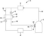
- FIG. 1is a schematic representation of a climate-control system according to the principles of the present disclosure
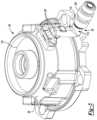
- FIG. 2is a cross-sectional view of a compressor of the climate-control system of FIG. 1 ;
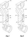
- FIG. 3is a perspective view of a non-orbiting scroll of the compression mechanism and a fluid-injection fitting assembly
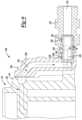
- FIG. 4is a partial cross-sectional view of the fluid-injection fitting assembly of FIG. 3 having a valve assembly in an open position;
- FIG. 5is a cross-sectional view of the valve assembly in the closed position
- FIG. 6is a cross-sectional view of the valve assembly in the open position
- FIG. 7is a partial cross-sectional view of an alternate fluid-injection fitting assembly having a valve assembly in a closed position
- FIG. 8is a partial cross-sectional view of the fluid-injection fitting assembly of FIG. 7 with the valve assembly in an open position;
- FIG. 9is a partial cross-sectional view of yet another alternate fluid-injection fitting assembly.
- FIG. 10is a perspective view of a transfer conduit of the fluid-injection fitting assembly of FIG. 9 having a valve assembly in a closed position;
- FIG. 11is a perspective view of the transfer conduit of the fluid-injection fitting assembly of FIG. 9 having the valve assembly in an open position;
- FIG. 12is a partial perspective view of an alternate non-orbiting scroll and an alternate fluid-injection fitting assembly
- FIG. 13is a partial cross-sectional view of the non-orbiting scroll and fluid-injection fitting assembly of FIG. 12 ;
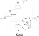
- FIG. 14is a schematic representation of an alternate climate-control system according to the principles of the present disclosure.
- FIG. 15is a perspective view of another alternate non-orbiting scroll and an alternate fluid-injection fitting assembly
- FIG. 16is a cross-sectional view of the non-orbiting scroll and fluid-injection fitting assembly of FIG. 15 ;
- FIG. 17is a cross-sectional view of an alternate orbiting scroll according to the principles of the present disclosure.
- Example embodimentsare provided so that this disclosure will be thorough, and will fully convey the scope to those who are skilled in the art. Numerous specific details are set forth such as examples of specific components, devices, and methods, to provide a thorough understanding of embodiments of the present disclosure. It will be apparent to those skilled in the art that specific details need not be employed, that example embodiments may be embodied in many different forms and that neither should be construed to limit the scope of the disclosure. In some example embodiments, well-known processes, well-known device structures, and well-known technologies are not described in detail.
- first, second, third, etc.may be used herein to describe various elements, components, regions, layers and/or sections, these elements, components, regions, layers and/or sections should not be limited by these terms. These terms may be only used to distinguish one element, component, region, layer or section from another region, layer or section. Terms such as “first,” “second,” and other numerical terms when used herein do not imply a sequence or order unless clearly indicated by the context. Thus, a first element, component, region, layer or section discussed below could be termed a second element, component, region, layer or section without departing from the teachings of the example embodiments.
- Spatially relative termssuch as “inner,” “outer,” “beneath,” “below,” “lower,” “above,” “upper,” and the like, may be used herein for ease of description to describe one element or feature's relationship to another element(s) or feature(s) as illustrated in the figures. Spatially relative terms may be intended to encompass different orientations of the device in use or operation in addition to the orientation depicted in the figures. For example, if the device in the figures is turned over, elements described as “below” or “beneath” other elements or features would then be oriented “above” the other elements or features. Thus, the example term “below” can encompass both an orientation of above and below. The device may be otherwise oriented (rotated 90 degrees or at other orientations) and the spatially relative descriptors used herein interpreted accordingly.
- a climate-control system 10may include a fluid-circuit having a compressor 12 , a first heat exchanger 14 (an outdoor heat exchanger such as a condenser or gas cooler, for example), first and second expansion devices 16 , 18 , a second heat exchanger 20 and a third heat exchanger 22 (an indoor heat exchanger such as an evaporator).
- the compressor 12may pump working fluid (e.g., refrigerant, carbon dioxide, etc.) through the circuit.
- the compressor 12may be a low-side compressor (i.e., a compressor in which the motor assembly is disposed within a suction chamber or suction-pressure region of the compressor), for example.
- the compressor 12may include a hermetic shell assembly 24 , a motor assembly 26 , a main bearing housing 28 , a compression mechanism 30 , a seal assembly 32 , a suction gas inlet fitting 34 (e.g., a first inlet of the compressor 12 ) and a fluid-injection fitting assembly 36 (e.g., a second inlet of the compressor 12 ).
- the shell assembly 24may generally form a compressor housing and may include a cylindrical shell 38 , an end cap 40 at an upper end thereof, a transversely extending muffler plate 42 and a base 44 at a lower end thereof.
- the end cap 40 and the muffler plate 42may generally define a discharge chamber 46
- the cylindrical shell 38 , the muffler plate 42 and the base 44may generally define a suction chamber 48 .
- a discharge fitting(not shown) may be attached to the shell assembly 24 at an opening (not shown) in the end cap 40 and may be in fluid communication with the first heat exchanger 14 .
- the suction gas inlet fitting 34may be attached to the shell assembly 24 at an opening 50 such that the suction gas inlet fitting 34 is in fluid communication with the third heat exchanger 22 .
- the muffler plate 42may include a discharge passage 52 extending therethrough that provides communication between the compression mechanism 30 and the discharge chamber 46 .
- the motor assembly 26may generally include a motor stator 54 , a rotor 56 and a driveshaft 58 .
- the motor stator 54may be fixedly coupled with shell 38 (e.g., press-fit into the shell 38 ).
- the driveshaft 58may be rotatably driven by the rotor 56 .
- the rotor 56may be press-fit onto the driveshaft 58 .
- the main bearing housing 28may be affixed to the shell 38 at a plurality of points in any desirable manner, such as staking, for example, and may axially support the compression mechanism 30 .
- the main bearing housing 28may include a bearing that rotatably supports one end of the driveshaft 58 .
- the other end of the driveshaft 58may be supported by a lower bearing housing 60 .
- the compression mechanism 30may generally include an orbiting scroll or first scroll member 62 and a non-orbiting scroll or second scroll member 64 .
- the orbiting scroll 62may include an endplate 66 having a spiral vane or wrap 68 on the upper surface thereof and an annular flat thrust surface 70 on the lower surface.
- the thrust surface 70may interface with the annular flat thrust bearing surface 72 on the main bearing housing 28 .
- a cylindrical hub 74may project downwardly from the thrust surface 70 and may have a drive bushing 76 rotatably disposed therein.
- the drive bushing 76may include an inner bore in which the driveshaft 58 is drivingly disposed.
- An Oldham couplingmay be engaged with the orbiting and non-orbiting scrolls 62 , 64 to prevent relative rotation therebetween.
- the non-orbiting scroll 64may include an endplate 84 having a spiral wrap 86 on a lower surface thereof.
- the spiral wrap 86may form a meshing engagement with the wrap 68 of the orbiting scroll 62 , thereby creating compression pockets, including an inlet pocket 90 (i.e., a radially outer pocket), intermediate pockets 92 , 94 , 96 (i.e., radially intermediate pockets), and an outlet pocket 98 (i.e., a radially inner pocket).
- the non-orbiting scroll 64may include a discharge passage 100 in communication with the outlet pocket 98 and an upwardly open recess 102 .
- the upwardly open recess 102may be in fluid communication with the discharge chamber 46 via the discharge passage 52 in the muffler plate 42 .
- the endplate 84may include a fluid-injection passage 104 formed therein.
- the fluid-injection passage 104may be in fluid communication with the fluid-injection fitting assembly 36 and with one or more of the intermediate pockets 92 , 94 , 96 , and may include a radially extending portion 106 and an axially extending portion 108 .
- the fluid-injection passage 104may allow working fluid from the fluid-injection fitting assembly 36 to flow into the one or more of the intermediate pockets 92 , 94 , 96 .
- the non-orbiting scroll 64may include an annular recess 110 in the upper surface thereof.
- the seal assembly 32may be located within the annular recess 110 .
- the seal assembly 32may be axially displaceable within the annular recess 110 relative to the shell assembly 24 and/or the non-orbiting scroll 64 to provide for axial displacement of the non-orbiting scroll 64 while maintaining a sealed engagement with the muffler plate 42 to isolate the discharge chamber 46 from the suction chamber 48 .
- pressure within the annular recess 110may urge the seal assembly 32 into engagement with the muffler plate 42 , and the spiral wrap 86 of the non-orbiting scroll 64 into engagement with the endplate 66 of the orbiting scroll 62 , during normal compressor operation.
- the fluid-injection fitting assembly 36may include a scroll fitting 114 , a transfer conduit 116 , a valve assembly 118 ( FIGS. 2 and 4 - 6 ), and a shell fitting 126 .
- the scroll fitting 114may be at least partially disposed in the shell 38 and may be attached to the non-orbiting scroll 64 via bolts 120 .
- the scroll fitting 114may include a passage 122 that is in fluid communication with the injection passage 104 at a first end and in fluid communication with the transfer conduit 116 and the valve assembly 118 at a second end.
- a sealing member 124e.g., a gasket
- the shell fitting 126(i.e., a second inlet) is attached to the shell 38 at an opening thereof.
- the transfer conduit 116may be at least partially disposed in the shell 38 and may be attached to the scroll fitting 114 at a first end and to the shell fitting 126 at a second end.
- the transfer conduit 116may be in fluid communication with the passage 122 of the scroll fitting 114 at the first end and may be in fluid communication with a passage 128 of the shell fitting 126 at the second end.
- a first sealing member 130(e.g., an O-ring) may be disposed in a groove 132 formed in the transfer conduit 116 at or near the first end and a second sealing member 134 (e.g., an O-ring) may be disposed in a groove 136 formed in the transfer conduit 116 at or near the second end.
- the first and second sealing members 130 , 134prevent leakage from or into the transfer conduit 116 , the scroll fitting 114 and/or the shell fitting 126 .
- the transfer conduit 116could be integrally formed with or a part of the scroll fitting 114 or the shell fitting 126 .
- the valve assembly 118may include a valve housing 138 , an end cap 140 a valve body 142 and a coiled spring 144 .
- the valve housing 138may be fixedly coupled to the scroll fitting 114 and may include an end wall 145 and a sidewall 146 that cooperate to define a valve-housing passage 147 .
- the end wall 145may define a first opening 148 and the sidewall 146 may define second openings 149 .
- the first opening 148is in fluid communication with the passage 122 of the scroll fitting 114 and also selectively in fluid communication with the second openings 149 via the valve-housing passage 147 .
- the second openings 149may be in fluid communication with the suction chamber 48 and selectively in fluid communication with the valve-housing passage 147 .
- the end cap 140is attached to the valve housing 138 at an end opposite the end wall 145 .
- the valve body 142 and the coiled spring 144are disposed in the valve-housing passage 147 of the valve housing 138 .
- the valve body 142may be disposed within the valve-housing passage 147 and movable relative to the valve housing 138 between a closed position and an open position. In the closed position ( FIG. 5 ), the valve body 142 may sealingly engage the end wall 145 to prevent fluid communication between the first opening 148 and the valve-housing passage 147 . In the open position ( FIG. 6 ), the valve body 142 may be spaced apart from the end wall 145 , thereby allowing fluid communication between the first opening 148 and the valve-housing passage 147 .
- the coiled spring 144is connected to the end cap 140 and the valve body 142 , and biases the valve body 142 into the closed position.
- the compressor 12is described above as a low-side scroll compressor (i.e., a compressor in which the motor assembly is disposed within a suction-pressure chamber within the shell), in some configurations, the compressor 12 could be a high-side compressor (i.e., a compressor in which the motor assembly is disposed within a discharge-pressure chamber within the shell).
- the compressor 12could be a high-side or low-side compressor and could be a rotary, reciprocating, or screw compressor, or any other suitable type of compressor.
- the first heat exchanger 14may be in fluid communication with the compressor 12 and may receive compressed working fluid from the compressor 12 via a discharge line 150 that is connected to the discharge fitting (not shown) of the compressor 12 .
- the first heat exchanger 14may transfer heat from the compressed working fluid to ambient air that may be forced over the first heat exchanger 14 .
- the first heat exchanger 14may transfer heat from the compressed working fluid to a stream of liquid such as water, for example.
- the first fluid passageway 152may include the first expansion device 16 (e.g., an expansion valve or capillary tube), a first conduit 154 of the second heat exchanger 20 , and the third heat exchanger 22 .
- the working fluid in the first fluid passageway 152flows through the conduit 154 of the second heat exchanger 20 and the first expansion device 16 where its temperature and pressure are lowered.
- the working fluidthen flows to the third heat exchanger 22 where the working fluid may absorb heat from a space to be cooled.
- the working fluidflows to the suction gas inlet fitting 34 (via a suction line 156 ) to be compressed by the compression mechanism 30 .
- a second portion of the working fluid from the first heat exchanger 14may flow to a second fluid passageway 158 (e.g., a fluid-injection passageway).
- the second fluid passageway 158may include the second expansion device 18 (e.g., an expansion valve or capillary tube) and a conduit 160 of the second heat exchanger 20 .
- the working fluid in the second fluid passageway 158may flow through the second expansion device 18 where its pressure is lowered.
- the working fluidthen flows through the conduit 160 of the second heat exchanger 20 where it absorbs heat from the working fluid flowing through the conduit 154 .
- the working fluidthen flows to the fluid-injection fitting assembly 36 and into the intermediate pocket 92 of the compression mechanism 30 (via the injection passage 104 ).
- the second fluid passageway 158 , the fluid-injection fitting assembly 36 , and the injection passage 104may define a fluid-injection circuit.
- the second heat exchanger 20may be a counter-flow heat exchanger as oppose to a parallel-flow heat exchanger.
- the system 10may not include the second heat exchanger 20 , e.g., if liquid injection (as opposed to vapor injection) is desired.
- a flooded start conditionis a condition where working fluid in a liquid phase (i.e., a mixture of gaseous and liquid working fluid or entirely liquid working fluid) may migrate into or otherwise be present in the compression pockets 90 , 92 , 94 , 96 , 98 of the compression mechanism 30 when the compressor 12 is switched from the OFF-mode to an ON-mode.
- high fluid pressuree.g., fluid pressures greater than or equal to 500 pounds per square inch (psi)
- psipounds per square inch
- intermediate-pressure working fluidmay flow through the fluid-injection circuit from the second fluid passageway 158 , through the fluid-injection fitting assembly 36 , through the injection passage 104 and into the intermediate compression pocket 92 ). If the high pressure working fluid in the compression pocket 92 and/or the fluid-injection circuit exceeds a predetermined threshold value (e.g., during a flooded start condition), the coiled spring 144 of the valve assembly 118 will compress, thereby moving the valve body 142 from the closed position ( FIG. 5 ) to the open position ( FIG. 6 ).
- a predetermined threshold valuee.g., during a flooded start condition
- valve body 142Once the valve body 142 is moved from the closed position to the open position, high pressure working fluid in the compression pocket 92 and/or the fluid-injection circuit (e.g., the passage 122 ) flows through the first opening 148 , the valve-housing passage 147 , and out the second openings 149 into the suction chamber 48 .
- the fluid-injection circuite.g., the passage 122
- the coiled spring 144may compress in response to high pressure working fluid in the compression pocket 92 being above a predetermined threshold value due to the compressor 12 experiencing a flooded start condition and not during normal operation of the system 10 . Stated another way, fluid pressures in the compression pocket 92 and in the fluid-injection circuit during normal operation of the system 10 are below the predetermined threshold value that causes the spring 144 to compress and the valve body 142 to move from the closed position to the open position.
- One of the benefits of the climate-control system 10 of the present disclosureis the reduction of pressure of the high pressure working fluid generated during a flooded start condition, which increases the reliability of the compressor 12 . That is, a flooded start condition may be detrimental to the reliability of the compressor 12 and, in turn, the efficient operation of the climate-control system 10 . By reducing the pressure of the high pressure working fluid generated during a flooded start condition, the compressor 12 is more reliable, which allows for efficient operation of the climate-control system 10 .
- climate-control system 10 of the present disclosureAnother benefit of the climate-control system 10 of the present disclosure is the prevention of damage to the gasket 124 and the reduction of moment on the fitting 114 due to venting excessively high pressure working fluid to the suction chamber 48 . This allows the gasket 124 to maintain a proper seal between the scroll 64 and the fitting 114 .
- FIGS. 7 - 8another fluid-injection fitting assembly 236 is provided.
- the fluid-injection fitting assembly 236may be incorporated into the compressor 12 instead of the fluid-injection fitting assembly 36 .
- the structure and function of the fluid-injection fitting assembly 236may be similar or identical to that of the fluid-injection fitting assembly 36 described above, apart from any exception noted below.
- the fluid-injection fitting assembly 236may include a scroll fitting 238 , a valve flap 240 and a transfer conduit (not shown).
- the scroll fitting 238may be at least partially disposed in the shell 38 and may be attached to the non-orbiting scroll 64 via bolts (not shown).
- the scroll fitting 238may include a first passage 242 and a second passage 243 .
- the first passage 242may be in fluid communication with the injection passage 104 at a first end and in fluid communication the transfer conduit at a second end.
- the second passage 243may be in fluid communication with the first passage 242 and in selective fluid communication with the suction chamber 48 .
- the valve flap 240may be movably mounted to the scroll fitting 238 (via fasteners 246 ; only one shown in FIGS. 7 and 8 ) between a closed position ( FIG. 7 ) and an open position ( FIG. 8 ). In the closed position, the valve flap 240 may be sealingly engaged with the scroll fitting 238 to prevent fluid communication between the first passage 242 and the suction chamber 48 . In the open position, the valve flap 240 may be spaced apart from the scroll fitting 238 , thereby allowing fluid communication between the first passage 242 and the suction chamber 48 (via the second passage 243 ).
- High pressure working fluid in the compression pocket 92may flow at least partially through a fluid-injection circuit (the fluid-injection circuit may be defined by the injection passage 104 , the passages 242 , 243 of the scroll fitting 238 , the transfer conduit (not shown), the shell fitting 126 and the second fluid passageway 158 ). If a pressure difference between high pressure working fluid in the compression pockets 90 , 92 , 94 , 96 , 98 (and/or the fluid-injection circuit) and working fluid in the suction chamber 48 exceeds a predetermined threshold, the valve flap 240 moves from the closed position to the open position.
- valve flap 240Once the valve flap 240 is moved from the closed position to the open position, high pressure working fluid in the compression pocket 92 and/or the fluid-injection circuit (e.g., the passages 242 , 243 ) is vented out into the suction chamber 48 .
- the valve flap 240moves from the open position back to the closed position once the pressure difference between the high pressure working fluid in the compression pockets 90 , 92 , 94 , 96 , 98 (and/or the fluid-injection circuit) and the working fluid in the suction chamber 48 is below the predetermined threshold.
- transfer conduit(not shown) may be similar or identical to that of the transfer conduit 116 described above, and therefore, will not be described again in detail.
- valve flap 240may move from the closed position to the open position in response to a pressure difference between high pressure working fluid in the compression pockets 90 , 92 , 94 , 96 , 98 (and/or the fluid-injection circuit) and working fluid in the suction chamber 48 exceeding a predetermined threshold value due to the compressor 12 experiencing a flooded start condition and not during normal operation of the system 10 .
- the pressure difference between high pressure working fluid in the compression pockets 90 , 92 , 94 , 96 , 98 (and/or the fluid-injection circuit) and working fluid in the suction chamber 48 during normal operation of the compressor 12is below the predetermined threshold value and would not cause the valve flap 240 to move from the closed position to the open position.
- the fluid-injection fitting assembly 336may be incorporated into the compressor 12 instead of the fluid-injection fitting assemblies 36 , 236 .
- the structure and function of the fluid-injection fitting assembly 336may be similar or identical to that of the fluid-injection fitting assemblies 36 , 236 described above, apart from any exception noted below.
- the fluid-injection fitting assembly 336may include a scroll fitting 338 and a transfer conduit 340 .
- the scroll fitting 338may be at least partially disposed in the shell 38 and may be attached to the non-orbiting scroll 64 via bolts 339 .
- the scroll fitting 338may include a fluid passage 342 that may be in fluid communication with the injection passage 104 at a first end and in fluid communication with the transfer conduit 340 at a second end.
- the transfer conduit 340may be at least partially disposed in the shell 38 and may be attached to the scroll fitting 338 at a first end and to the shell fitting 126 at a second end.
- a passage 345 of the transfer conduit 340may be in fluid communication with the fluid passage 342 of the scroll fitting 338 at the first end and may be in fluid communication with the passage 128 of the shell fitting 126 at the second end.
- a first sealing member 346e.g., an O-ring
- a second sealing member 350e.g., an O-ring
- the first and second sealing members 346 , 350prevent leakage from or into the transfer conduit 340 , the scroll fitting 338 and/or the shell fitting 126 .
- the fluid-injection fitting assembly 336also includes a valve flap 354 that may be movably mounted to the transfer conduit 340 (via a fastener 355 ) between a closed position ( FIG. 10 ) and an open position ( FIG. 11 ). In the closed position, the valve flap 354 may be sealingly engaged with the transfer conduit 340 to prevent fluid communication between the passage 345 and the suction chamber 48 . In the open position, the valve flap 354 may be spaced apart from the transfer conduit 340 , thereby allowing fluid communication between the passage 345 and the suction chamber 48 via an aperture 347 in the transfer conduit 340 .
- high pressure working fluid in the compression pocket 92may flow at least partially through a fluid-injection circuit (the fluid-injection circuit may be defined by the injection passage 104 , the passage 342 of the scroll fitting 338 , the passage 345 of the transfer conduit 340 , the passage 128 of the shell fitting 126 and the second fluid passageway 158 ). If a pressure difference between high pressure working fluid in the compression pockets 90 , 92 , 94 , 96 , 98 (and/or the fluid-injection circuit) and working fluid in the suction chamber 48 exceeds a predetermined threshold, the valve flap 354 moves from the closed position to the open position.
- valve flap 354Once the valve flap 354 is moved from the closed position to the open position, high pressure working fluid in the compression pocket 92 and/or the fluid-injection circuit (e.g., the passage 345 ) is vented out into the suction chamber 48 .
- the valve flap 354moves from the open position back to the closed position once the pressure difference between high pressure working fluid in the compression pockets 90 , 92 , 94 , 96 , 98 (and/or the fluid-injection circuit) and working fluid in the suction chamber 48 is below the predetermined threshold.
- compression mechanism 430may be incorporated into the compressor 12 instead of the compression mechanism 30 described above.
- the structure and function of the compression mechanism 430may be similar or identical to that of the compression mechanism 30 described above, apart from any exception noted below.
- the compression mechanism 430may generally include an orbiting scroll or first scroll member (not shown), a non-orbiting scroll or second scroll member 440 and a valve assembly 442 .
- the structure and function of the orbiting scrollmay be similar or identical to that of the orbiting scroll 62 described above, and therefore, will not be described again in detail.
- the non-orbiting scroll 440may include an endplate 444 having a spiral wrap (not shown) projecting downwardly from the endplate 444 .
- the spiral wrapmay form a meshing engagement with the wrap (not shown) of the orbiting scroll, thereby creating compression pockets (not shown).
- the endplate 444may include an injection passage 446 formed therein.
- the injection passage 446may be in fluid communication with the fluid-injection fitting assembly 436 and one or more of the intermediate pockets of the compression pockets.
- the injection passage 446may also be in selective fluid communication with the suction chamber 48 via the valve assembly 442 .
- the injection passage 446may allow working fluid from fluid-injection fitting assembly 436 to flow into the one or more of the intermediate pockets.
- the valve assembly 442may include a valve housing 448 , a valve body 450 , a coiled spring 452 and an end cap 454 .
- the valve housing 448may be coupled to the end plate 444 of the non-orbiting scroll 440 .
- the valve body 450may be disposed within the valve housing 448 and may be translatable between a closed position and an open position. In the closed position, the valve body 450 may prevent fluid communication between the injection passage 446 and the suction chamber 48 . In the open position, the valve body 450 may allow fluid communication between the injection passage 446 and the suction chamber 48 (via openings 455 , 456 in the valve housing 448 and the end cap 454 , respectively).
- the coiled spring 452is connected to the end cap 454 and the valve body 450 , and biases the valve body 450 into the closed position.
- the end cap 454is coupled to an end of the valve housing 448 .
- the fluid-injection fitting assembly 436may be incorporated into the compressor 12 instead of the fluid-injection fitting assemblies 36 , 236 , 336 described above.
- the structure and function of the fluid-injection fitting assembly 436may be similar or identical to that of the fluid-injection fitting assemblies 36 , 236 , 336 described above, apart from any exception noted below.
- the fluid-injection fitting assembly 436may include a scroll fitting 460 and a transfer conduit 462 .
- the scroll fitting 460may be at least partially disposed in the shell 38 and may be attached to the non-orbiting scroll 440 via bolts 463 .
- the scroll fitting 460may include a passage 464 that is in fluid communication with the injection passage 446 at a first end and in fluid communication with the transfer conduit 462 at a second end.
- a sealing member 466e.g., a gasket is disposed between the non-orbiting scroll 440 and the scroll fitting 460 to prevent leakage from or into the injection passage 446 and/or the scroll fitting 460 .
- transfer conduit 462may be similar or identical to the transfer conduit 116 described above, and therefore, will not be described again in detail.
- High pressure working fluid in an intermediate compression pocketmay flow at least partially through a fluid-injection circuit (the fluid-injection circuit may be defined by the injection passage 446 , the passage 464 of the scroll fitting 460 , the transfer conduit 462 , the shell fitting 126 and the second fluid passageway 158 ). If fluid pressures in the compression pockets and the fluid-injection circuit exceeds a predetermined threshold value, the coiled spring 452 of the valve assembly 442 will compress, thereby moving the valve body 450 from the closed position to the open position. Once the valve body 450 is moved from the closed position to the open position, high pressure working fluid in the intermediate compression pocket and/or the fluid-injection circuit (e.g., the passage 446 ) flows through the valve housing 448 and into the suction chamber 48 .
- the fluid-injection circuitmay be defined by the injection passage 446 , the passage 464 of the scroll fitting 460 , the transfer conduit 462 , the shell fitting 126 and the second fluid passageway 158 .
- climate-control system 510is provided.
- the structure and function of the climate control system 510may be similar or identical to that of climate-control system 10 described above, apart from any exception noted below.
- the climate-control system 510may include a fluid-circuit having a compressor 512 , a first heat exchanger 514 (an outdoor heat exchanger such as a condenser or gas cooler, for example), first and second expansion devices 516 , 518 , a second heat exchanger 520 and a third heat exchanger 522 (an indoor heat exchanger such as an evaporator).
- a first heat exchanger 514an outdoor heat exchanger such as a condenser or gas cooler, for example
- first and second expansion devices 516 , 518a second heat exchanger 520 and a third heat exchanger 522 (an indoor heat exchanger such as an evaporator).
- the structure and the function of the compressor 512 , the first heat exchanger 514 , the first and second expansion devices 516 , 518 , the second heat exchanger 520 and the third heat exchanger 522may be similar or identical to that of the compressor 12 , the first heat exchanger 14 , the first and second expansion devices 16 , 18 , the second heat exchanger 20 and the third heat exchanger 22 , respectively, described above, and therefore, will not be described again in detail.
- the climate-control system 510may also include a conduit 554 extending between a first fluid passageway 556 and a second fluid passageway 558 .
- the first fluid passageway 556may include the first expansion device 516 and the third heat exchanger 522
- the second fluid passageway 558may include the second expansion device 518 .
- a valve 562(e.g., a pressure-relief valve) may be disposed along the conduit 554 and may vent high pressure working fluid generated in an intermediate compression pocket (not shown) of the compression mechanism (not shown) of the compressor 512 to a suction chamber (not shown) of the compressor 512 . That is, if fluid pressures in the compression pockets due to the compressor 512 experiencing a flooded start condition exceeds a predetermined threshold value, the valve 562 will open and the high pressure working fluid may flow through a second inlet 564 (i.e., a fluid-injection fitting assembly), through the conduit 554 and into the suction chamber (via a suction line 566 and first inlet 568 (i.e., suction inlet gas fitting)). It should be understood that during normal operation of the system 510 , fluid pressures are below the predetermined threshold value, and thus, the valve 562 is in the closed position.
- a second inlet 564i.e., a fluid-injection fitting assembly
- compression mechanism 630may be incorporated into the compressor 12 instead of the compression mechanisms 30 , 430 described above.
- the structure and function of the compression mechanism 630may be similar or identical to that of the compression mechanisms 30 , 430 described above, apart from any exception noted below.
- the compression mechanism 630may generally include an orbiting scroll or first scroll member (not shown), a non-orbiting scroll or second scroll member 640 and a valve assembly 642 .
- the structure and function of the orbiting scrollmay be similar or identical to that of the orbiting scroll 62 described above, and therefore, will not be described again in detail.
- the non-orbiting scroll 640may include an endplate 644 having a spiral wrap 645 projecting downwardly from the endplate 644 .
- the spiral wrap 645may form a meshing engagement with the wrap (not shown) of the orbiting scroll, thereby creating compression pockets (not shown).
- the endplate 644may include an injection passage 646 and a venting passage 647 formed therein.
- the injection passage 646may be in fluid communication with the fluid-injection fitting assembly 636 and one or more of the compression pockets.
- the injection passage 646may allow working fluid from the fluid-injection fitting assembly 636 to flow into the one or more of the compression pockets.
- the venting passage 647may be in fluid communication with the compression pockets and with the suction chamber 48 (via the valve assembly 642 ).
- valve assembly 642may be similar or identical to that of the valve assembly 442 , described above, and therefore, will not be described again in detail.
- the valve assembly 642may be coupled to the endplate 644 and may allow fluid communication between the compression pockets and the suction chamber 48 .
- the fluid-injection fitting assembly 636may include a scroll fitting 660 and a transfer conduit 662 .
- the scroll fitting 660may be at least partially disposed in the shell 38 and may be attached to the non-orbiting scroll 640 via bolts 663 .
- the scroll fitting 660may include a passage 664 that is in fluid communication with the injection passage 646 at a first end and in fluid communication with the transfer conduit 662 at a second end.
- a sealing member 666e.g., a gasket is disposed between the non-orbiting scroll 640 and the scroll fitting 660 to prevent leakage from or into the injection passage 646 and/or the scroll fitting 660 .
- transfer conduit 662may be similar or identical to the transfer conduit 116 , 462 described above, and therefore, will not be described again in detail.
- the high pressure working fluidmay flow through the venting passage 647 and into the suction chamber 48 (via the valve assembly 642 ). It should be understood that during normal operation of the system, fluid pressures are below the predetermined threshold value, and thus, the valve assembly 642 is in the closed position.
- compression mechanism 730is provided.
- the compression mechanism 730may be incorporated into the compressor 12 instead of the compression mechanism 30 , 430 , 630 described above.
- the structure and function of the compression mechanism 730may be similar or identical to that of the compression mechanism 30 , 430 , 630 described above, apart from any exception noted below.
- the compression mechanism 730may generally include a non-orbiting scroll (not shown), an orbiting scroll 762 and a valve assembly 742 .
- the structure and function of the non-orbiting scrollmay be similar or identical to that of the non-orbiting scroll 64 described above, and therefore, will not be described again in detail.
- the orbiting scroll 762may include an endplate 766 having a spiral vane or wrap 768 on the upper surface thereof and an annular flat thrust surface 770 on the lower surface.
- the wrap 768may form a meshing engagement with the wrap (not shown) of the non-orbiting scroll, thereby creating compression pockets.
- the endplate 766may include a venting passage 779 that may be in fluid communication with the compression pockets and with the suction chamber 48 (via the valve assembly 742 ).
- the venting passage 779may have an axial extending portion 780 and a radial extending portion 782 .
- the thrust surface 770may interface with the annular flat thrust bearing surface 72 on the main bearing housing 28 .
- a cylindrical hub 774may project downwardly from the thrust surface 770 and may have a drive bushing (not shown) rotatably disposed therein.
- valve assembly 742may be similar or identical to that of the valve assembly 442 , 642 described above, and therefore, will not be described again in detail.
- the valve assembly 742may be coupled to the endplate 766 and may allow fluid communication between the compression pockets and the suction chamber 48 .
- the high pressure working fluidmay flow through the venting passage 779 and into the suction chamber 48 (via the valve assembly 742 ). It should be understood that during normal operation of the system, fluid pressures are below the predetermined threshold value, and thus, the valve assembly 742 is in the closed position.
Landscapes
- Engineering & Computer Science (AREA)
- Mechanical Engineering (AREA)
- General Engineering & Computer Science (AREA)
- Physics & Mathematics (AREA)
- Thermal Sciences (AREA)
- Fluid Mechanics (AREA)
- Rotary Pumps (AREA)
- Applications Or Details Of Rotary Compressors (AREA)
Abstract
Description
Claims (21)
Priority Applications (2)
| Application Number | Priority Date | Filing Date | Title |
|---|---|---|---|
| US16/814,487US11656003B2 (en) | 2019-03-11 | 2020-03-10 | Climate-control system having valve assembly |
| PCT/US2020/022030WO2020185860A1 (en) | 2019-03-11 | 2020-03-11 | Climate-control system having valve assembly |
Applications Claiming Priority (2)
| Application Number | Priority Date | Filing Date | Title |
|---|---|---|---|
| US201962816626P | 2019-03-11 | 2019-03-11 | |
| US16/814,487US11656003B2 (en) | 2019-03-11 | 2020-03-10 | Climate-control system having valve assembly |
Publications (2)
| Publication Number | Publication Date |
|---|---|
| US20200291943A1 US20200291943A1 (en) | 2020-09-17 |
| US11656003B2true US11656003B2 (en) | 2023-05-23 |
Family
ID=72422463
Family Applications (1)
| Application Number | Title | Priority Date | Filing Date |
|---|---|---|---|
| US16/814,487Active2041-02-09US11656003B2 (en) | 2019-03-11 | 2020-03-10 | Climate-control system having valve assembly |
Country Status (2)
| Country | Link |
|---|---|
| US (1) | US11656003B2 (en) |
| WO (1) | WO2020185860A1 (en) |
Families Citing this family (9)
| Publication number | Priority date | Publication date | Assignee | Title |
|---|---|---|---|---|
| US7988433B2 (en) | 2009-04-07 | 2011-08-02 | Emerson Climate Technologies, Inc. | Compressor having capacity modulation assembly |
| US10995753B2 (en) | 2018-05-17 | 2021-05-04 | Emerson Climate Technologies, Inc. | Compressor having capacity modulation assembly |
| US11655813B2 (en) | 2021-07-29 | 2023-05-23 | Emerson Climate Technologies, Inc. | Compressor modulation system with multi-way valve |
| US12259163B2 (en) | 2022-06-01 | 2025-03-25 | Copeland Lp | Climate-control system with thermal storage |
| US11846287B1 (en) | 2022-08-11 | 2023-12-19 | Copeland Lp | Scroll compressor with center hub |
| US11965507B1 (en) | 2022-12-15 | 2024-04-23 | Copeland Lp | Compressor and valve assembly |
| US12416308B2 (en) | 2022-12-28 | 2025-09-16 | Copeland Lp | Compressor with shutdown assembly |
| US12173708B1 (en) | 2023-12-07 | 2024-12-24 | Copeland Lp | Heat pump systems with capacity modulation |
| US12163523B1 (en) | 2023-12-15 | 2024-12-10 | Copeland Lp | Compressor and valve assembly |
Citations (179)
| Publication number | Priority date | Publication date | Assignee | Title |
|---|---|---|---|---|
| US1493064A (en)* | 1922-08-22 | 1924-05-06 | Ross M Brasington | Compressor regulator |
| US3884599A (en) | 1973-06-11 | 1975-05-20 | Little Inc A | Scroll-type positive fluid displacement apparatus |
| DE3142744A1 (en) | 1980-10-31 | 1982-06-09 | Hitachi, Ltd., Tokyo | REFRIGERATION PRODUCTION SYSTEM |
| US4383805A (en) | 1980-11-03 | 1983-05-17 | The Trane Company | Gas compressor of the scroll type having delayed suction closing capacity modulation |
| US4431388A (en) | 1982-03-05 | 1984-02-14 | The Trane Company | Controlled suction unloading in a scroll compressor |
| US4475360A (en) | 1982-02-26 | 1984-10-09 | Hitachi, Ltd. | Refrigeration system incorporating scroll type compressor |
| US4497615A (en) | 1983-07-25 | 1985-02-05 | Copeland Corporation | Scroll-type machine |
| US4505651A (en)* | 1982-08-07 | 1985-03-19 | Sanden Corporation | Scroll type compressor with displacement adjusting mechanism |
| EP0144169A2 (en) | 1983-11-08 | 1985-06-12 | Sanden Corporation | Scroll type compressor with displacement adjusting mechanism |
| US4557675A (en) | 1983-06-17 | 1985-12-10 | Hitachi, Ltd. | Scroll-type fluid machine with back pressure chamber biasing an orbiting scroll member |
| US4669962A (en) | 1984-08-22 | 1987-06-02 | Hitachi, Ltd. | Scroll compressor with pressure differential maintained for supplying oil |
| US4676075A (en) | 1985-02-15 | 1987-06-30 | Hitachi, Ltd. | Scroll-type compressor for helium gas |
| US4696627A (en) | 1985-08-15 | 1987-09-29 | Nippondenso Co., Ltd. | Scroll compressor |
| US4767293A (en) | 1986-08-22 | 1988-08-30 | Copeland Corporation | Scroll-type machine with axially compliant mounting |
| US4774816A (en) | 1986-12-04 | 1988-10-04 | Hitachi, Ltd. | Air conditioner or refrigerating plant incorporating scroll compressor |
| US4818195A (en) | 1986-02-26 | 1989-04-04 | Hitachi, Ltd. | Scroll compressor with valved port for each compression chamber |
| JPH01106990A (en) | 1987-10-19 | 1989-04-24 | Daikin Ind Ltd | Capacity controlling mechanism for scroll type compressor |
| US4904165A (en) | 1988-08-02 | 1990-02-27 | Carrier Corporation | Muffler/check valve assembly for scroll compressor |
| US4904164A (en) | 1987-06-30 | 1990-02-27 | Sanden Corporation | Scroll type compressor with variable displacement mechanism |
| US4940385A (en) | 1989-04-25 | 1990-07-10 | Gurth Max Ira | Rotary disc pump |
| US4940395A (en) | 1987-12-08 | 1990-07-10 | Sanden Corporation | Scroll type compressor with variable displacement mechanism |
| AU607745B2 (en) | 1987-03-20 | 1991-03-14 | Sanden Corporation | Scroll type compressor |
| JPH0381588A (en) | 1989-08-23 | 1991-04-05 | Hitachi Ltd | Scroll compressor capacity control device |
| JPH03138473A (en) | 1989-10-25 | 1991-06-12 | Hitachi Ltd | variable speed scroll compressor |
| US5074760A (en) | 1988-08-12 | 1991-12-24 | Mitsubishi Jukogyo Kabushiki Kaisha | Scroll type compressor |
| US5087170A (en) | 1989-01-23 | 1992-02-11 | Hitachi, Ltd. | Rotary compressor |
| EP0479421A1 (en) | 1990-10-01 | 1992-04-08 | Copeland Corporation | Scroll machine with floating seal |
| CN1061647A (en) | 1990-11-16 | 1992-06-03 | 三菱重工业株式会社 | Scroll compressor |
| US5156539A (en) | 1990-10-01 | 1992-10-20 | Copeland Corporation | Scroll machine with floating seal |
| US5169294A (en) | 1991-12-06 | 1992-12-08 | Carrier Corporation | Pressure ratio responsive unloader |
| USRE34148E (en) | 1985-06-18 | 1992-12-22 | Sanden Corporation | Scroll type compressor with variable displacement mechanism |
| JPH051677A (en) | 1991-06-27 | 1993-01-08 | Hitachi Ltd | Scroll compressor |
| US5192195A (en) | 1990-11-14 | 1993-03-09 | Mitsubishi Jukogyo Kabushiki Kaisha | Scroll type compressor with separate control block |
| US5193987A (en) | 1990-11-14 | 1993-03-16 | Mitsubishi Jukogyo Kabushiki Kaisha | Scroll type compressor |
| JPH05157061A (en)* | 1991-12-05 | 1993-06-22 | Daikin Ind Ltd | Compressor |
| US5240389A (en) | 1991-07-26 | 1993-08-31 | Kabushiki Kaisha Toshiba | Scroll type compressor |
| US5336058A (en) | 1992-02-18 | 1994-08-09 | Sanden Corporation | Scroll-type compressor with variable displacement mechanism |
| US5356271A (en) | 1992-02-06 | 1994-10-18 | Mitsubishi Jukogyo Kabushiki Kaisha | Capacity control mechanism for scroll-type compressor |
| US5395224A (en) | 1990-07-31 | 1995-03-07 | Copeland Corporation | Scroll machine lubrication system including the orbiting scroll member |
| US5451146A (en) | 1992-04-01 | 1995-09-19 | Nippondenso Co., Ltd. | Scroll-type variable-capacity compressor with bypass valve |
| US5469716A (en) | 1994-05-03 | 1995-11-28 | Copeland Corporation | Scroll compressor with liquid injection |
| US5551846A (en) | 1995-12-01 | 1996-09-03 | Ford Motor Company | Scroll compressor capacity control valve |
| US5557897A (en) | 1992-02-20 | 1996-09-24 | Braas Gmbh | Fastening device for a roof sealing strip or the like |
| US5562426A (en) | 1994-06-03 | 1996-10-08 | Kabushiki Kaisha Toyoda Jidoshokki Seisakusho | Scroll type refrigerant compressor |
| EP0747598A2 (en) | 1995-06-07 | 1996-12-11 | Copeland Corporation | Capacity modulated scroll machine |
| CN1137614A (en) | 1995-06-07 | 1996-12-11 | 科普兰公司 | Power modulation scroll machine |
| US5591014A (en) | 1993-11-29 | 1997-01-07 | Copeland Corporation | Scroll machine with reverse rotation protection |
| US5607288A (en) | 1993-11-29 | 1997-03-04 | Copeland Corporation | Scroll machine with reverse rotation protection |
| US5611674A (en) | 1995-06-07 | 1997-03-18 | Copeland Corporation | Capacity modulated scroll machine |
| US5613841A (en) | 1995-06-07 | 1997-03-25 | Copeland Corporation | Capacity modulated scroll machine |
| US5639225A (en) | 1994-05-30 | 1997-06-17 | Nippondenso Co., Ltd. | Scroll type compressor |
| US5640854A (en) | 1995-06-07 | 1997-06-24 | Copeland Corporation | Scroll machine having liquid injection controlled by internal valve |
| CN1158945A (en) | 1995-12-19 | 1997-09-10 | 科普兰公司 | Scroll machine with capacity modulation |
| US5674058A (en) | 1994-06-08 | 1997-10-07 | Nippondenso Co., Ltd. | Scroll-type refrigerant compressor |
| US5803716A (en) | 1993-11-29 | 1998-09-08 | Copeland Corporation | Scroll machine with reverse rotation protection |
| US5810573A (en) | 1995-11-30 | 1998-09-22 | Sanyo Electric Co., Ltd. | Scroll compressor having a baffle plate and oil passages in the orbiting scroll member |
| US5833442A (en) | 1995-11-18 | 1998-11-10 | Park; Wan Pyo | Scroll-type compressor having improved pressure equalizing passage configuration |
| US5855475A (en) | 1995-12-05 | 1999-01-05 | Matsushita Electric Industrial Co., Ltd. | Scroll compressor having bypass valves |
| US5885063A (en) | 1996-05-07 | 1999-03-23 | Matshushita Electric Industrial Co., Ltd. | Variable capacity scroll compressor |
| WO1999031355A1 (en) | 1997-12-12 | 1999-06-24 | Scroll Technologies | Improved scroll compressor assembly |
| US5993171A (en) | 1996-06-25 | 1999-11-30 | Sanden Corporation | Scroll-type compressor with variable displacement mechanism |
| US5993177A (en) | 1996-05-21 | 1999-11-30 | Sanden Corporation | Scroll type compressor with improved variable displacement mechanism |
| US5996364A (en) | 1998-07-13 | 1999-12-07 | Carrier Corporation | Scroll compressor with unloader valve between economizer and suction |
| US6047557A (en) | 1995-06-07 | 2000-04-11 | Copeland Corporation | Adaptive control for a refrigeration system using pulse width modulated duty cycle scroll compressor |
| JP2000161263A (en) | 1998-11-27 | 2000-06-13 | Mitsubishi Electric Corp | Capacity control scroll compressor |
| US6077057A (en) | 1997-08-29 | 2000-06-20 | Scroll Technologies | Scroll compressor with back pressure seal protection during reverse rotation |
| US6102671A (en) | 1997-09-04 | 2000-08-15 | Matsushita Electric Industrial Co., Ltd. | Scroll compressor |
| US6120255A (en) | 1998-01-16 | 2000-09-19 | Copeland Corporation | Scroll machine with capacity modulation |
| US6123517A (en) | 1997-11-24 | 2000-09-26 | Copeland Corporation | Scroll machine with capacity modulation |
| US6132179A (en) | 1997-09-09 | 2000-10-17 | Sanden Corporation | Scroll type compressor enabling a soft start with a simple structure |
| US6164940A (en) | 1998-09-11 | 2000-12-26 | Sanden Corporation | Scroll type compressor in which a soft starting mechanism is improved with a simple structure |
| US6171086B1 (en) | 1997-11-03 | 2001-01-09 | Carrier Corporation | Scroll compressor with pressure equalization groove |
| US6176686B1 (en) | 1999-02-19 | 2001-01-23 | Copeland Corporation | Scroll machine with capacity modulation |
| US6190138B1 (en) | 1998-06-12 | 2001-02-20 | Scroll Technologies | Flow valve for correcting reverse rotation in scroll compressor |
| US6196816B1 (en) | 1998-08-17 | 2001-03-06 | Carrier Corporation | Unequal injection ports for scroll compressors |
| CN1289011A (en) | 1999-09-21 | 2001-03-28 | 科普兰公司 | Compressor Pulse Width Modulation |
| US6210120B1 (en) | 1999-03-19 | 2001-04-03 | Scroll Technologies | Low charge protection vent |
| CN1292850A (en) | 1998-03-05 | 2001-04-25 | 开利公司 | Scroll compressor with pressure ratio-pressure relief valve |
| US6231316B1 (en) | 1998-07-01 | 2001-05-15 | Denso Corporation | Scroll-type variable-capacity compressor |
| US20010010800A1 (en) | 1998-03-19 | 2001-08-02 | Hirokatsu Kohsokabe | Displacement type fluid machine |
| US6273691B1 (en) | 1996-07-22 | 2001-08-14 | Matsushita Electric Industrial Co., Ltd. | Scroll gas compressor having asymmetric bypass holes |
| US6293767B1 (en) | 2000-02-28 | 2001-09-25 | Copeland Corporation | Scroll machine with asymmetrical bleed hole |
| US6295821B1 (en) | 1997-09-15 | 2001-10-02 | Mad Tech Llc | Digital control valve for refrigeration system |
| US6299417B1 (en) | 1999-10-04 | 2001-10-09 | Lg Electronics, Inc. | Back pressure structure of intermediate pressure of scroll compressor |
| JP2001304144A (en) | 2000-04-20 | 2001-10-31 | Fujitsu General Ltd | Horizontal scroll compressor |
| US6350111B1 (en) | 2000-08-15 | 2002-02-26 | Copeland Corporation | Scroll machine with ported orbiting scroll member |
| US20020028150A1 (en) | 2000-02-18 | 2002-03-07 | Natsuki Kawabata | Scroll compressor |
| US20020039540A1 (en) | 2000-09-29 | 2002-04-04 | Kazuhiro Kuroki | Scroll type compressor and method for compressing gas |
| EP1199474A2 (en) | 2000-10-16 | 2002-04-24 | Copeland Corporation | Scroll compressor |
| US6412293B1 (en) | 2000-10-11 | 2002-07-02 | Copeland Corporation | Scroll machine with continuous capacity modulation |
| US6413058B1 (en) | 2000-11-21 | 2002-07-02 | Scroll Technologies | Variable capacity modulation for scroll compressor |
| CN1088159C (en) | 1997-11-14 | 2002-07-24 | 三菱重工业株式会社 | Compressor having capacity-controlling mechanism with abrasion-free cylinder |
| US6430959B1 (en) | 2002-02-11 | 2002-08-13 | Scroll Technologies | Economizer injection ports extending through scroll wrap |
| EP1241417A1 (en) | 2001-03-16 | 2002-09-18 | Copeland Corporation | Digital controller for scroll compressor condensing unit |
| US6454551B2 (en) | 2000-05-24 | 2002-09-24 | Kabushiki Kaisha Toyoda Jidoshokki Seisakusho | Seal structure in a scroll type compressor |
| US6457948B1 (en) | 2001-04-25 | 2002-10-01 | Copeland Corporation | Diagnostic system for a compressor |
| US6464481B2 (en) | 2000-09-29 | 2002-10-15 | Kabushiki Kaisha Toyota Jidoshokki | Scroll compressors |
| US6506036B2 (en) | 2000-09-13 | 2003-01-14 | Kabushiki Kaisha Toyota Jidoshokki | Scroll compressors |
| US20030012659A1 (en) | 2000-10-16 | 2003-01-16 | Seibel Stephen M. | Dual volume-ratio scroll machine |
| US6544016B2 (en) | 2000-09-14 | 2003-04-08 | Kabushiki Kaisha Toyota Jidoshokki | Scroll compressors |
| US6558143B2 (en) | 2000-09-18 | 2003-05-06 | Kabushiki Kaisha Toyota Jidoshokki | Scroll compressors |
| US6589035B1 (en) | 1996-10-04 | 2003-07-08 | Hitachi, Ltd. | Scroll compressor having a valved back-pressure chamber and a bypass for over-compression |
| CN1434216A (en) | 2002-01-24 | 2003-08-06 | 科普兰公司 | Scroll compressor with steam injection |
| US6619062B1 (en)* | 1999-12-06 | 2003-09-16 | Daikin Industries, Ltd. | Scroll compressor and air conditioner |
| US20040071571A1 (en) | 2001-06-29 | 2004-04-15 | Kazuhide Uchida | Scroll compressor |
| US20040146419A1 (en) | 2002-11-06 | 2004-07-29 | Masahiro Kawaguchi | Variable displacement mechanism for scroll type compressor |
| US20040197204A1 (en) | 2002-12-27 | 2004-10-07 | Akihito Yamanouchi | Variable displacement mechanism for scroll type compressor |
| US6821092B1 (en) | 2003-07-15 | 2004-11-23 | Copeland Corporation | Capacity modulated scroll compressor |
| US20050019177A1 (en) | 2003-07-26 | 2005-01-27 | Lg Electronics Inc. | Variable capacity scroll compressor |
| US20050019178A1 (en) | 2003-07-26 | 2005-01-27 | Lg Electronics Inc. | Variable capacity scroll compressor |
| EP1507085A1 (en) | 2003-08-11 | 2005-02-16 | Mitsubishi Heavy Industries, Ltd. | Scroll compressor |
| US6881046B2 (en) | 2002-03-13 | 2005-04-19 | Daikin Industries, Ltd. | Scroll type fluid machine |
| US6884042B2 (en) | 2003-06-26 | 2005-04-26 | Scroll Technologies | Two-step self-modulating scroll compressor |
| US20060165542A1 (en) | 2002-12-11 | 2006-07-27 | Katsumi Sakitani | Volume expander and fluid machine |
| CN2821233Y (en) | 2005-07-13 | 2006-09-27 | 乐金电子(天津)电器有限公司 | Volume regulator for rotary compressor |
| US20060269432A1 (en) | 2005-05-31 | 2006-11-30 | Scroll Technologies | Recesses for pressure equalization in a scroll compressor |
| CN1896518A (en) | 2005-07-12 | 2007-01-17 | 乐金电子(天津)电器有限公司 | Vortex compressor and its vacuum preventer |
| US20070036661A1 (en) | 2005-08-12 | 2007-02-15 | Copeland Corporation | Capacity modulated scroll compressor |
| US20070053782A1 (en) | 2003-09-08 | 2007-03-08 | Masakazu Okamoto | Rotary type expander and fluid machinery |
| US7197890B2 (en) | 2004-09-10 | 2007-04-03 | Carrier Corporation | Valve for preventing unpowered reverse run at shutdown |
| CN1952398A (en) | 2005-10-21 | 2007-04-25 | 爱默生气候技术公司 | Compressor capacity modulation system and method |
| US20070092390A1 (en) | 2005-10-26 | 2007-04-26 | Copeland Corporation | Scroll compressor |
| CN1963214A (en) | 2005-11-10 | 2007-05-16 | 乐金电子(天津)电器有限公司 | Volume varying device for rotating blade type compressor |
| US7229261B2 (en) | 2003-10-17 | 2007-06-12 | Matsushita Electric Industrial Co., Ltd. | Scroll compressor having an annular recess located outside an annular seal portion and another recess communicating with suction port of fixed scroll |
| US7228710B2 (en) | 2005-05-31 | 2007-06-12 | Scroll Technologies | Indentation to optimize vapor injection through ports extending through scroll wrap |
| US20070130973A1 (en) | 2005-05-04 | 2007-06-14 | Scroll Technologies | Refrigerant system with multi-speed scroll compressor and economizer circuit |
| JP2007154761A (en) | 2005-12-05 | 2007-06-21 | Daikin Ind Ltd | Scroll compressor |
| US20070231172A1 (en) | 2006-03-31 | 2007-10-04 | Kazuyuki Fujimura | Scroll fluid machine |
| US7278832B2 (en) | 2004-01-07 | 2007-10-09 | Carrier Corporation | Scroll compressor with enlarged vapor injection port area |
| US20070237664A1 (en) | 2006-04-06 | 2007-10-11 | Lg Electronics Inc. | Backflow preventing apparatus for compressor |
| US20070245892A1 (en) | 2004-06-10 | 2007-10-25 | Achates Power, Llc | Two-Cycle, Opposed-Piston Internal Combustion Engine |
| US20080025861A1 (en) | 2004-09-28 | 2008-01-31 | Takeyoshi Okawa | Sliding Element and Fluid Machine |
| US7326039B2 (en) | 2004-11-11 | 2008-02-05 | Lg Electronics Inc. | Apparatus for varying capacity of scroll compressor |
| US20080107555A1 (en) | 2006-11-07 | 2008-05-08 | Scroll Technologies | Scroll compressor with vapor injection and unloader port |
| US20080159892A1 (en) | 2006-12-29 | 2008-07-03 | Industrial Technology Research Institute | Scroll type compressor |
| US7404706B2 (en) | 2005-11-08 | 2008-07-29 | Anest Iwata Corporation | Scroll fluid machine having oil-supply holes being formed through a reinforcement bearing plate on a rear surface of the orbiting scroll |
| US20080196445A1 (en) | 2005-06-07 | 2008-08-21 | Alexander Lifson | Variable Speed Compressor Motor Control for Low Speed Operation |
| US20080223057A1 (en)* | 2005-10-26 | 2008-09-18 | Alexander Lifson | Refrigerant System with Pulse Width Modulated Components and Variable Speed Compressor |
| JP2008248775A (en) | 2007-03-30 | 2008-10-16 | Mitsubishi Electric Corp | Scroll compressor |
| JP2008267707A (en) | 2007-04-20 | 2008-11-06 | Scroll Technol | Refrigerant system having multi-speed scroll compressor and economizer circuit |
| US20080286118A1 (en) | 2007-05-18 | 2008-11-20 | Emerson Climate Technologies, Inc. | Capacity modulated scroll compressor system and method |
| US20090013701A1 (en) | 2006-03-10 | 2009-01-15 | Alexander Lifson | Refrigerant system with control to address flooded compressor operation |
| US20090068048A1 (en) | 2007-09-11 | 2009-03-12 | Stover Robert C | Compressor Sealing Arrangement |
| US20090074593A1 (en) | 2006-03-31 | 2009-03-19 | Young-Se Joo | Apparatus For Preventing Vacuum Of Scroll Compressor |
| US20090071183A1 (en) | 2007-07-02 | 2009-03-19 | Christopher Stover | Capacity modulated compressor |
| US20090110570A1 (en) | 2007-10-30 | 2009-04-30 | Yong-Il Cho | Scroll compressor |
| US7547202B2 (en) | 2006-12-08 | 2009-06-16 | Emerson Climate Technologies, Inc. | Scroll compressor with capacity modulation |
| US20090196781A1 (en) | 2008-01-31 | 2009-08-06 | Lg Electronics Inc. | Mode changing apparatus for a scroll compressor |
| US20090297377A1 (en) | 2008-05-30 | 2009-12-03 | Stover Robert C | Compressor having capacity modulation system |
| US20090297378A1 (en) | 2008-05-30 | 2009-12-03 | Stover Robert C | Compressor having capacity modulation system |
| US20090297380A1 (en) | 2008-05-30 | 2009-12-03 | Stover Robert C | Compressor having capacity modulation system |
| US20090297379A1 (en) | 2008-05-30 | 2009-12-03 | Stover Robert C | Compressor Having Output Adjustment Assembly Including Piston Actuation |
| US20100111741A1 (en) | 2008-10-31 | 2010-05-06 | Hitachi Appliances, Inc. | Scroll compressor |
| US7717687B2 (en) | 2007-03-23 | 2010-05-18 | Emerson Climate Technologies, Inc. | Scroll compressor with compliant retainer |
| US20100135836A1 (en) | 2008-12-03 | 2010-06-03 | Stover Robert C | Scroll Compressor Having Capacity Modulation System |
| US20100158731A1 (en) | 2008-05-30 | 2010-06-24 | Masao Akei | Compressor having capacity modulation system |
| US7771178B2 (en) | 2006-12-22 | 2010-08-10 | Emerson Climate Technologies, Inc. | Vapor injection system for a scroll compressor |
| US20100254841A1 (en) | 2009-04-07 | 2010-10-07 | Masao Akei | Compressor having capacity modulation assembly |
| US7815423B2 (en) | 2005-07-29 | 2010-10-19 | Emerson Climate Technologies, Inc. | Compressor with fluid injection system |
| US20100303659A1 (en) | 2009-05-29 | 2010-12-02 | Stover Robert C | Compressor having piston assembly |
| US20100300659A1 (en) | 2009-05-29 | 2010-12-02 | Stover Robert C | Compressor Having Capacity Modulation Or Fluid Injection Systems |
| US20110052437A1 (en)* | 2009-08-28 | 2011-03-03 | Sanyo Electric Co., Ltd. | Scroll compressor |
| US20110103988A1 (en) | 2008-05-30 | 2011-05-05 | Emerson Climate Technologies, Inc. | Compressor having capacity modulation system |
| US20120009076A1 (en)* | 2010-07-12 | 2012-01-12 | Kim Pilhwan | Scroll compressor |
| US20120107163A1 (en) | 2010-10-28 | 2012-05-03 | Emerson Climate Technologies, Inc. | Compressor seal assembly |
| US20130081710A1 (en)* | 2011-09-30 | 2013-04-04 | Emerson Climate Technologies, Inc. | Direct-suction compressor |
| US20140134031A1 (en) | 2012-11-15 | 2014-05-15 | Emerson Climate Technologies, Inc. | Compressor |
| US20140134030A1 (en) | 2012-11-15 | 2014-05-15 | Emerson Climate Technologies, Inc. | Compressor valve system and assembly |
| US20140154124A1 (en) | 2012-11-30 | 2014-06-05 | Emerson Climate Technologies, Inc. | Scroll compressor with variable volume ratio port in orbiting scroll |
| US20140154121A1 (en) | 2012-11-30 | 2014-06-05 | Emerson Climate Technologies, Inc. | Compressor with capacity modulation and variable volume ratio |
| US20150330386A1 (en) | 2014-05-15 | 2015-11-19 | Emerson Climate Technologies, Inc. | Capacity-modulated scroll compressor |
| WO2017071641A1 (en) | 2015-10-29 | 2017-05-04 | Emerson Climate Technologies, Inc. | Compressor having capacity modulation system |
| WO2017130401A1 (en)* | 2016-01-29 | 2017-08-03 | 三菱電機株式会社 | Scroll compressor and heat pump device |
| US20170241417A1 (en) | 2016-02-24 | 2017-08-24 | Lg Electronics Inc. | Scroll compressor |
| US20170342983A1 (en) | 2016-05-25 | 2017-11-30 | Lg Electronics Inc. | Scroll compressor |
| US20170342984A1 (en) | 2016-05-30 | 2017-11-30 | Lg Electronics Inc. | Scroll compressor |
| US20180216618A1 (en) | 2017-02-01 | 2018-08-02 | Lg Electronics Inc. | Scroll compressor |
| US10066622B2 (en) | 2015-10-29 | 2018-09-04 | Emerson Climate Technologies, Inc. | Compressor having capacity modulation system |
| US20190353164A1 (en) | 2018-05-17 | 2019-11-21 | Emerson Climate Technologies, Inc. | Compressor Having Capacity Modulation Assembly |
- 2020
- 2020-03-10USUS16/814,487patent/US11656003B2/enactiveActive
- 2020-03-11WOPCT/US2020/022030patent/WO2020185860A1/ennot_activeCeased
Patent Citations (245)
| Publication number | Priority date | Publication date | Assignee | Title |
|---|---|---|---|---|
| US1493064A (en)* | 1922-08-22 | 1924-05-06 | Ross M Brasington | Compressor regulator |
| US3884599A (en) | 1973-06-11 | 1975-05-20 | Little Inc A | Scroll-type positive fluid displacement apparatus |
| DE3142744A1 (en) | 1980-10-31 | 1982-06-09 | Hitachi, Ltd., Tokyo | REFRIGERATION PRODUCTION SYSTEM |
| US4382370A (en) | 1980-10-31 | 1983-05-10 | Hitachi, Ltd. | Refrigerating system using scroll type compressor |
| US4383805A (en) | 1980-11-03 | 1983-05-17 | The Trane Company | Gas compressor of the scroll type having delayed suction closing capacity modulation |
| US4475360A (en) | 1982-02-26 | 1984-10-09 | Hitachi, Ltd. | Refrigeration system incorporating scroll type compressor |
| US4431388A (en) | 1982-03-05 | 1984-02-14 | The Trane Company | Controlled suction unloading in a scroll compressor |
| US4505651A (en)* | 1982-08-07 | 1985-03-19 | Sanden Corporation | Scroll type compressor with displacement adjusting mechanism |
| US4557675A (en) | 1983-06-17 | 1985-12-10 | Hitachi, Ltd. | Scroll-type fluid machine with back pressure chamber biasing an orbiting scroll member |
| US4497615A (en) | 1983-07-25 | 1985-02-05 | Copeland Corporation | Scroll-type machine |
| EP0144169A2 (en) | 1983-11-08 | 1985-06-12 | Sanden Corporation | Scroll type compressor with displacement adjusting mechanism |
| US4669962A (en) | 1984-08-22 | 1987-06-02 | Hitachi, Ltd. | Scroll compressor with pressure differential maintained for supplying oil |
| US4676075A (en) | 1985-02-15 | 1987-06-30 | Hitachi, Ltd. | Scroll-type compressor for helium gas |
| USRE34148E (en) | 1985-06-18 | 1992-12-22 | Sanden Corporation | Scroll type compressor with variable displacement mechanism |
| US4696627A (en) | 1985-08-15 | 1987-09-29 | Nippondenso Co., Ltd. | Scroll compressor |
| US4818195A (en) | 1986-02-26 | 1989-04-04 | Hitachi, Ltd. | Scroll compressor with valved port for each compression chamber |
| US4767293A (en) | 1986-08-22 | 1988-08-30 | Copeland Corporation | Scroll-type machine with axially compliant mounting |
| US4774816A (en) | 1986-12-04 | 1988-10-04 | Hitachi, Ltd. | Air conditioner or refrigerating plant incorporating scroll compressor |
| AU607745B2 (en) | 1987-03-20 | 1991-03-14 | Sanden Corporation | Scroll type compressor |
| US4904164A (en) | 1987-06-30 | 1990-02-27 | Sanden Corporation | Scroll type compressor with variable displacement mechanism |
| JPH01106990A (en) | 1987-10-19 | 1989-04-24 | Daikin Ind Ltd | Capacity controlling mechanism for scroll type compressor |
| JP2550612B2 (en) | 1987-10-19 | 1996-11-06 | ダイキン工業株式会社 | Capacity control mechanism of scroll compressor |
| US4940395A (en) | 1987-12-08 | 1990-07-10 | Sanden Corporation | Scroll type compressor with variable displacement mechanism |
| US4904165A (en) | 1988-08-02 | 1990-02-27 | Carrier Corporation | Muffler/check valve assembly for scroll compressor |
| US5074760A (en) | 1988-08-12 | 1991-12-24 | Mitsubishi Jukogyo Kabushiki Kaisha | Scroll type compressor |
| US5087170A (en) | 1989-01-23 | 1992-02-11 | Hitachi, Ltd. | Rotary compressor |
| US4940385A (en) | 1989-04-25 | 1990-07-10 | Gurth Max Ira | Rotary disc pump |
| JPH0381588A (en) | 1989-08-23 | 1991-04-05 | Hitachi Ltd | Scroll compressor capacity control device |
| JPH03138473A (en) | 1989-10-25 | 1991-06-12 | Hitachi Ltd | variable speed scroll compressor |
| US5395224A (en) | 1990-07-31 | 1995-03-07 | Copeland Corporation | Scroll machine lubrication system including the orbiting scroll member |
| CN1060699A (en) | 1990-10-01 | 1992-04-29 | 科普兰公司 | The scroll machine of band floating seal |
| US5156539A (en) | 1990-10-01 | 1992-10-20 | Copeland Corporation | Scroll machine with floating seal |
| EP0479421A1 (en) | 1990-10-01 | 1992-04-08 | Copeland Corporation | Scroll machine with floating seal |
| CN1028379C (en) | 1990-10-01 | 1995-05-10 | 科普兰公司 | Scroll machine with floating seal |
| US5193987A (en) | 1990-11-14 | 1993-03-16 | Mitsubishi Jukogyo Kabushiki Kaisha | Scroll type compressor |
| US5192195A (en) | 1990-11-14 | 1993-03-09 | Mitsubishi Jukogyo Kabushiki Kaisha | Scroll type compressor with separate control block |
| CN1061647A (en) | 1990-11-16 | 1992-06-03 | 三菱重工业株式会社 | Scroll compressor |
| JPH051677A (en) | 1991-06-27 | 1993-01-08 | Hitachi Ltd | Scroll compressor |
| US5240389A (en) | 1991-07-26 | 1993-08-31 | Kabushiki Kaisha Toshiba | Scroll type compressor |
| JPH05157061A (en)* | 1991-12-05 | 1993-06-22 | Daikin Ind Ltd | Compressor |
| US5169294A (en) | 1991-12-06 | 1992-12-08 | Carrier Corporation | Pressure ratio responsive unloader |
| US5356271A (en) | 1992-02-06 | 1994-10-18 | Mitsubishi Jukogyo Kabushiki Kaisha | Capacity control mechanism for scroll-type compressor |
| US5336058A (en) | 1992-02-18 | 1994-08-09 | Sanden Corporation | Scroll-type compressor with variable displacement mechanism |
| US5557897A (en) | 1992-02-20 | 1996-09-24 | Braas Gmbh | Fastening device for a roof sealing strip or the like |
| US5451146A (en) | 1992-04-01 | 1995-09-19 | Nippondenso Co., Ltd. | Scroll-type variable-capacity compressor with bypass valve |
| US5577897A (en) | 1992-04-01 | 1996-11-26 | Nippondenso Co., Ltd. | Scroll-type variable-capacity compressor having two control valves |
| US5803716A (en) | 1993-11-29 | 1998-09-08 | Copeland Corporation | Scroll machine with reverse rotation protection |
| US5607288A (en) | 1993-11-29 | 1997-03-04 | Copeland Corporation | Scroll machine with reverse rotation protection |
| US5591014A (en) | 1993-11-29 | 1997-01-07 | Copeland Corporation | Scroll machine with reverse rotation protection |
| US5469716A (en) | 1994-05-03 | 1995-11-28 | Copeland Corporation | Scroll compressor with liquid injection |
| US5639225A (en) | 1994-05-30 | 1997-06-17 | Nippondenso Co., Ltd. | Scroll type compressor |
| US5562426A (en) | 1994-06-03 | 1996-10-08 | Kabushiki Kaisha Toyoda Jidoshokki Seisakusho | Scroll type refrigerant compressor |
| US5674058A (en) | 1994-06-08 | 1997-10-07 | Nippondenso Co., Ltd. | Scroll-type refrigerant compressor |
| US5741120A (en) | 1995-06-07 | 1998-04-21 | Copeland Corporation | Capacity modulated scroll machine |
| CN1908437A (en) | 1995-06-07 | 2007-02-07 | 科普兰公司 | Capacity modulated scroll machine |
| US5611674A (en) | 1995-06-07 | 1997-03-18 | Copeland Corporation | Capacity modulated scroll machine |
| US5640854A (en) | 1995-06-07 | 1997-06-24 | Copeland Corporation | Scroll machine having liquid injection controlled by internal valve |
| US6086335A (en) | 1995-06-07 | 2000-07-11 | Copeland Corporation | Capacity modulated scroll machine having one or more pin members movably disposed for restricting the radius of the orbiting scroll member |
| EP0747598A2 (en) | 1995-06-07 | 1996-12-11 | Copeland Corporation | Capacity modulated scroll machine |
| US6047557A (en) | 1995-06-07 | 2000-04-11 | Copeland Corporation | Adaptive control for a refrigeration system using pulse width modulated duty cycle scroll compressor |
| CN1137614A (en) | 1995-06-07 | 1996-12-11 | 科普兰公司 | Power modulation scroll machine |
| US5613841A (en) | 1995-06-07 | 1997-03-25 | Copeland Corporation | Capacity modulated scroll machine |
| US5833442A (en) | 1995-11-18 | 1998-11-10 | Park; Wan Pyo | Scroll-type compressor having improved pressure equalizing passage configuration |
| US5810573A (en) | 1995-11-30 | 1998-09-22 | Sanyo Electric Co., Ltd. | Scroll compressor having a baffle plate and oil passages in the orbiting scroll member |
| US5551846A (en) | 1995-12-01 | 1996-09-03 | Ford Motor Company | Scroll compressor capacity control valve |
| US5855475A (en) | 1995-12-05 | 1999-01-05 | Matsushita Electric Industrial Co., Ltd. | Scroll compressor having bypass valves |
| US5678985A (en) | 1995-12-19 | 1997-10-21 | Copeland Corporation | Scroll machine with capacity modulation |
| CN1158945A (en) | 1995-12-19 | 1997-09-10 | 科普兰公司 | Scroll machine with capacity modulation |
| US5885063A (en) | 1996-05-07 | 1999-03-23 | Matshushita Electric Industrial Co., Ltd. | Variable capacity scroll compressor |
| US5993177A (en) | 1996-05-21 | 1999-11-30 | Sanden Corporation | Scroll type compressor with improved variable displacement mechanism |
| US5993171A (en) | 1996-06-25 | 1999-11-30 | Sanden Corporation | Scroll-type compressor with variable displacement mechanism |
| US6273691B1 (en) | 1996-07-22 | 2001-08-14 | Matsushita Electric Industrial Co., Ltd. | Scroll gas compressor having asymmetric bypass holes |
| US6769888B2 (en) | 1996-10-04 | 2004-08-03 | Hitachi, Ltd. | Scroll compressor having a valved back pressure chamber and a bypass for overcompression |
| US6589035B1 (en) | 1996-10-04 | 2003-07-08 | Hitachi, Ltd. | Scroll compressor having a valved back-pressure chamber and a bypass for over-compression |
| US7354259B2 (en) | 1996-10-04 | 2008-04-08 | Hitachi, Ltd. | Scroll compressor having a valved back pressure chamber and a bypass for overcompression |
| US7118358B2 (en) | 1996-10-04 | 2006-10-10 | Hitachi, Ltd. | Scroll compressor having a back-pressure chamber control valve |
| US7137796B2 (en) | 1996-10-04 | 2006-11-21 | Hitachi, Ltd. | Scroll compressor |
| US6077057A (en) | 1997-08-29 | 2000-06-20 | Scroll Technologies | Scroll compressor with back pressure seal protection during reverse rotation |
| US6102671A (en) | 1997-09-04 | 2000-08-15 | Matsushita Electric Industrial Co., Ltd. | Scroll compressor |
| US6132179A (en) | 1997-09-09 | 2000-10-17 | Sanden Corporation | Scroll type compressor enabling a soft start with a simple structure |
| US6295821B1 (en) | 1997-09-15 | 2001-10-02 | Mad Tech Llc | Digital control valve for refrigeration system |
| US6171086B1 (en) | 1997-11-03 | 2001-01-09 | Carrier Corporation | Scroll compressor with pressure equalization groove |
| CN1088159C (en) | 1997-11-14 | 2002-07-24 | 三菱重工业株式会社 | Compressor having capacity-controlling mechanism with abrasion-free cylinder |
| US6123517A (en) | 1997-11-24 | 2000-09-26 | Copeland Corporation | Scroll machine with capacity modulation |
| WO1999031355A1 (en) | 1997-12-12 | 1999-06-24 | Scroll Technologies | Improved scroll compressor assembly |
| US6120255A (en) | 1998-01-16 | 2000-09-19 | Copeland Corporation | Scroll machine with capacity modulation |
| CN1292850A (en) | 1998-03-05 | 2001-04-25 | 开利公司 | Scroll compressor with pressure ratio-pressure relief valve |
| US6406279B2 (en) | 1998-03-19 | 2002-06-18 | Hitachi, Ltd. | Displacement type fluid machine |
| US20010010800A1 (en) | 1998-03-19 | 2001-08-02 | Hirokatsu Kohsokabe | Displacement type fluid machine |
| US6190138B1 (en) | 1998-06-12 | 2001-02-20 | Scroll Technologies | Flow valve for correcting reverse rotation in scroll compressor |
| US6231316B1 (en) | 1998-07-01 | 2001-05-15 | Denso Corporation | Scroll-type variable-capacity compressor |
| US5996364A (en) | 1998-07-13 | 1999-12-07 | Carrier Corporation | Scroll compressor with unloader valve between economizer and suction |
| US6196816B1 (en) | 1998-08-17 | 2001-03-06 | Carrier Corporation | Unequal injection ports for scroll compressors |
| US6164940A (en) | 1998-09-11 | 2000-12-26 | Sanden Corporation | Scroll type compressor in which a soft starting mechanism is improved with a simple structure |
| JP2000161263A (en) | 1998-11-27 | 2000-06-13 | Mitsubishi Electric Corp | Capacity control scroll compressor |
| US6176686B1 (en) | 1999-02-19 | 2001-01-23 | Copeland Corporation | Scroll machine with capacity modulation |
| US6210120B1 (en) | 1999-03-19 | 2001-04-03 | Scroll Technologies | Low charge protection vent |
| US6213731B1 (en) | 1999-09-21 | 2001-04-10 | Copeland Corporation | Compressor pulse width modulation |
| CN1995756A (en) | 1999-09-21 | 2007-07-11 | 科普兰公司 | Scroll mechanism |
| USRE40257E1 (en) | 1999-09-21 | 2008-04-22 | Emerson Climate Technologies, Inc. | Compressor pulse width modulation |
| CN1289011A (en) | 1999-09-21 | 2001-03-28 | 科普兰公司 | Compressor Pulse Width Modulation |
| US6299417B1 (en) | 1999-10-04 | 2001-10-09 | Lg Electronics, Inc. | Back pressure structure of intermediate pressure of scroll compressor |
| US6619062B1 (en)* | 1999-12-06 | 2003-09-16 | Daikin Industries, Ltd. | Scroll compressor and air conditioner |
| US20020028150A1 (en) | 2000-02-18 | 2002-03-07 | Natsuki Kawabata | Scroll compressor |
| US6293767B1 (en) | 2000-02-28 | 2001-09-25 | Copeland Corporation | Scroll machine with asymmetrical bleed hole |
| JP2001304144A (en) | 2000-04-20 | 2001-10-31 | Fujitsu General Ltd | Horizontal scroll compressor |
| US6454551B2 (en) | 2000-05-24 | 2002-09-24 | Kabushiki Kaisha Toyoda Jidoshokki Seisakusho | Seal structure in a scroll type compressor |
| USRE40344E1 (en) | 2000-08-15 | 2008-05-27 | Emerson Climate Technologies, Inc. | Scroll machine with ported orbiting scroll member |
| US6350111B1 (en) | 2000-08-15 | 2002-02-26 | Copeland Corporation | Scroll machine with ported orbiting scroll member |
| US6506036B2 (en) | 2000-09-13 | 2003-01-14 | Kabushiki Kaisha Toyota Jidoshokki | Scroll compressors |
| US6544016B2 (en) | 2000-09-14 | 2003-04-08 | Kabushiki Kaisha Toyota Jidoshokki | Scroll compressors |
| US6558143B2 (en) | 2000-09-18 | 2003-05-06 | Kabushiki Kaisha Toyota Jidoshokki | Scroll compressors |
| US6464481B2 (en) | 2000-09-29 | 2002-10-15 | Kabushiki Kaisha Toyota Jidoshokki | Scroll compressors |
| US20020039540A1 (en) | 2000-09-29 | 2002-04-04 | Kazuhiro Kuroki | Scroll type compressor and method for compressing gas |
| US6412293B1 (en) | 2000-10-11 | 2002-07-02 | Copeland Corporation | Scroll machine with continuous capacity modulation |
| CN1707104A (en) | 2000-10-11 | 2005-12-14 | 科普兰公司 | Vortex machine with continuous power regulation |
| US8475140B2 (en) | 2000-10-16 | 2013-07-02 | Emerson Climate Technologies, Inc. | Dual volume-ratio scroll machine |
| US20030012659A1 (en) | 2000-10-16 | 2003-01-16 | Seibel Stephen M. | Dual volume-ratio scroll machine |
| US6679683B2 (en) | 2000-10-16 | 2004-01-20 | Copeland Corporation | Dual volume-ratio scroll machine |
| US20070269326A1 (en) | 2000-10-16 | 2007-11-22 | Seibel Stephen M | Dual volume-ratio scroll machine |
| EP1199474A2 (en) | 2000-10-16 | 2002-04-24 | Copeland Corporation | Scroll compressor |
| US6413058B1 (en) | 2000-11-21 | 2002-07-02 | Scroll Technologies | Variable capacity modulation for scroll compressor |
| EP1241417A1 (en) | 2001-03-16 | 2002-09-18 | Copeland Corporation | Digital controller for scroll compressor condensing unit |
| CN1382912A (en) | 2001-04-25 | 2002-12-04 | 科普兰公司 | Diagnostic system of compressor |
| US6457948B1 (en) | 2001-04-25 | 2002-10-01 | Copeland Corporation | Diagnostic system for a compressor |
| CN100334352C (en) | 2001-04-25 | 2007-08-29 | 爱默生气候技术公司 | Diagnostic system of compressor |
| US20040071571A1 (en) | 2001-06-29 | 2004-04-15 | Kazuhide Uchida | Scroll compressor |
| CN1800647A (en) | 2002-01-24 | 2006-07-12 | 科普兰公司 | Scroll compressor with vapor injection |
| CN1434216A (en) | 2002-01-24 | 2003-08-06 | 科普兰公司 | Scroll compressor with steam injection |
| US6430959B1 (en) | 2002-02-11 | 2002-08-13 | Scroll Technologies | Economizer injection ports extending through scroll wrap |
| US6881046B2 (en) | 2002-03-13 | 2005-04-19 | Daikin Industries, Ltd. | Scroll type fluid machine |
| CN1475673A (en) | 2002-07-15 | 2004-02-18 | Turbo machine having dual volume ratio | |
| CN100523505C (en) | 2002-07-15 | 2009-08-05 | 爱默生气候技术公司 | Turbo machine having dual volume ratio |
| US20040146419A1 (en) | 2002-11-06 | 2004-07-29 | Masahiro Kawaguchi | Variable displacement mechanism for scroll type compressor |
| US20060165542A1 (en) | 2002-12-11 | 2006-07-27 | Katsumi Sakitani | Volume expander and fluid machine |
| US20040197204A1 (en) | 2002-12-27 | 2004-10-07 | Akihito Yamanouchi | Variable displacement mechanism for scroll type compressor |
| US6984114B2 (en) | 2003-06-26 | 2006-01-10 | Scroll Technologies | Two-step self-modulating scroll compressor |
| US6884042B2 (en) | 2003-06-26 | 2005-04-26 | Scroll Technologies | Two-step self-modulating scroll compressor |
| US6821092B1 (en) | 2003-07-15 | 2004-11-23 | Copeland Corporation | Capacity modulated scroll compressor |
| US20050019177A1 (en) | 2003-07-26 | 2005-01-27 | Lg Electronics Inc. | Variable capacity scroll compressor |
| CN100343521C (en) | 2003-07-26 | 2007-10-17 | Lg电子株式会社 | Variable capacity scroll compressor |
| US7513753B2 (en) | 2003-07-26 | 2009-04-07 | Lg Electronics Inc. | Variable capacity scroll compressor |
| CN1576603A (en) | 2003-07-26 | 2005-02-09 | Lg电子株式会社 | Variable capacity scroll compressor |
| US20050019178A1 (en) | 2003-07-26 | 2005-01-27 | Lg Electronics Inc. | Variable capacity scroll compressor |
| US20050053507A1 (en) | 2003-08-11 | 2005-03-10 | Makoto Takeuchi | Scroll compressor |
| US7344365B2 (en) | 2003-08-11 | 2008-03-18 | Mitsubishi Heavy Industries, Ltd. | Scroll compressor with bypass holes communicating with an intake chamber |
| EP1507085A1 (en) | 2003-08-11 | 2005-02-16 | Mitsubishi Heavy Industries, Ltd. | Scroll compressor |
| US20070053782A1 (en) | 2003-09-08 | 2007-03-08 | Masakazu Okamoto | Rotary type expander and fluid machinery |
| US7229261B2 (en) | 2003-10-17 | 2007-06-12 | Matsushita Electric Industrial Co., Ltd. | Scroll compressor having an annular recess located outside an annular seal portion and another recess communicating with suction port of fixed scroll |
| US7278832B2 (en) | 2004-01-07 | 2007-10-09 | Carrier Corporation | Scroll compressor with enlarged vapor injection port area |
| US20070245892A1 (en) | 2004-06-10 | 2007-10-25 | Achates Power, Llc | Two-Cycle, Opposed-Piston Internal Combustion Engine |
| US7197890B2 (en) | 2004-09-10 | 2007-04-03 | Carrier Corporation | Valve for preventing unpowered reverse run at shutdown |
| US20080025861A1 (en) | 2004-09-28 | 2008-01-31 | Takeyoshi Okawa | Sliding Element and Fluid Machine |
| US7326039B2 (en) | 2004-11-11 | 2008-02-05 | Lg Electronics Inc. | Apparatus for varying capacity of scroll compressor |
| US20070130973A1 (en) | 2005-05-04 | 2007-06-14 | Scroll Technologies | Refrigerant system with multi-speed scroll compressor and economizer circuit |
| US7228710B2 (en) | 2005-05-31 | 2007-06-12 | Scroll Technologies | Indentation to optimize vapor injection through ports extending through scroll wrap |
| US20060269432A1 (en) | 2005-05-31 | 2006-11-30 | Scroll Technologies | Recesses for pressure equalization in a scroll compressor |
| US20080196445A1 (en) | 2005-06-07 | 2008-08-21 | Alexander Lifson | Variable Speed Compressor Motor Control for Low Speed Operation |
| CN1896518A (en) | 2005-07-12 | 2007-01-17 | 乐金电子(天津)电器有限公司 | Vortex compressor and its vacuum preventer |
| CN2821233Y (en) | 2005-07-13 | 2006-09-27 | 乐金电子(天津)电器有限公司 | Volume regulator for rotary compressor |
| US7815423B2 (en) | 2005-07-29 | 2010-10-19 | Emerson Climate Technologies, Inc. | Compressor with fluid injection system |
| US20070036661A1 (en) | 2005-08-12 | 2007-02-15 | Copeland Corporation | Capacity modulated scroll compressor |
| CN1952398A (en) | 2005-10-21 | 2007-04-25 | 爱默生气候技术公司 | Compressor capacity modulation system and method |
| US20070092390A1 (en) | 2005-10-26 | 2007-04-26 | Copeland Corporation | Scroll compressor |
| US20080223057A1 (en)* | 2005-10-26 | 2008-09-18 | Alexander Lifson | Refrigerant System with Pulse Width Modulated Components and Variable Speed Compressor |
| US7404706B2 (en) | 2005-11-08 | 2008-07-29 | Anest Iwata Corporation | Scroll fluid machine having oil-supply holes being formed through a reinforcement bearing plate on a rear surface of the orbiting scroll |
| CN1963214A (en) | 2005-11-10 | 2007-05-16 | 乐金电子(天津)电器有限公司 | Volume varying device for rotating blade type compressor |
| JP2007154761A (en) | 2005-12-05 | 2007-06-21 | Daikin Ind Ltd | Scroll compressor |
| US20090013701A1 (en) | 2006-03-10 | 2009-01-15 | Alexander Lifson | Refrigerant system with control to address flooded compressor operation |
| US20090074593A1 (en) | 2006-03-31 | 2009-03-19 | Young-Se Joo | Apparatus For Preventing Vacuum Of Scroll Compressor |
| US20070231172A1 (en) | 2006-03-31 | 2007-10-04 | Kazuyuki Fujimura | Scroll fluid machine |
| US20070237664A1 (en) | 2006-04-06 | 2007-10-11 | Lg Electronics Inc. | Backflow preventing apparatus for compressor |
| US7585164B2 (en) | 2006-04-06 | 2009-09-08 | Lg Electronics Inc. | Backflow preventing apparatus for compressor |
| US7674098B2 (en) | 2006-11-07 | 2010-03-09 | Scroll Technologies | Scroll compressor with vapor injection and unloader port |
| US20080107555A1 (en) | 2006-11-07 | 2008-05-08 | Scroll Technologies | Scroll compressor with vapor injection and unloader port |
| US7547202B2 (en) | 2006-12-08 | 2009-06-16 | Emerson Climate Technologies, Inc. | Scroll compressor with capacity modulation |
| US7771178B2 (en) | 2006-12-22 | 2010-08-10 | Emerson Climate Technologies, Inc. | Vapor injection system for a scroll compressor |
| US20080159892A1 (en) | 2006-12-29 | 2008-07-03 | Industrial Technology Research Institute | Scroll type compressor |
| US7611345B2 (en) | 2006-12-29 | 2009-11-03 | Industrial Technology Research Institute | Structure for preventing axial leakage in scroll compressor |
| US7717687B2 (en) | 2007-03-23 | 2010-05-18 | Emerson Climate Technologies, Inc. | Scroll compressor with compliant retainer |
| JP2008248775A (en) | 2007-03-30 | 2008-10-16 | Mitsubishi Electric Corp | Scroll compressor |
| JP2008267707A (en) | 2007-04-20 | 2008-11-06 | Scroll Technol | Refrigerant system having multi-speed scroll compressor and economizer circuit |
| US20080286118A1 (en) | 2007-05-18 | 2008-11-20 | Emerson Climate Technologies, Inc. | Capacity modulated scroll compressor system and method |
| US20090071183A1 (en) | 2007-07-02 | 2009-03-19 | Christopher Stover | Capacity modulated compressor |
| US20090068048A1 (en) | 2007-09-11 | 2009-03-12 | Stover Robert C | Compressor Sealing Arrangement |
| US20090110570A1 (en) | 2007-10-30 | 2009-04-30 | Yong-Il Cho | Scroll compressor |
| US20090196781A1 (en) | 2008-01-31 | 2009-08-06 | Lg Electronics Inc. | Mode changing apparatus for a scroll compressor |
| US20100158731A1 (en) | 2008-05-30 | 2010-06-24 | Masao Akei | Compressor having capacity modulation system |
| US8790098B2 (en) | 2008-05-30 | 2014-07-29 | Emerson Climate Technologies, Inc. | Compressor having output adjustment assembly |
| WO2009155109A2 (en) | 2008-05-30 | 2009-12-23 | Emerson Climate Technologies, Inc. | Compressor having capacity modulation system |
| US8313318B2 (en) | 2008-05-30 | 2012-11-20 | Emerson Climate Technologies, Inc. | Compressor having capacity modulation system |
| US20090297379A1 (en) | 2008-05-30 | 2009-12-03 | Stover Robert C | Compressor Having Output Adjustment Assembly Including Piston Actuation |
| US20090297380A1 (en) | 2008-05-30 | 2009-12-03 | Stover Robert C | Compressor having capacity modulation system |
| EP2307728B1 (en) | 2008-05-30 | 2016-08-10 | Emerson Climate Technologies, Inc. | Compressor having output adjustment assembly including piston actuation |
| US20090297378A1 (en) | 2008-05-30 | 2009-12-03 | Stover Robert C | Compressor having capacity modulation system |
| US8517704B2 (en) | 2008-05-30 | 2013-08-27 | Emerson Climate Technologies, Inc. | Compressor having capacity modulation system |
| US20140356211A1 (en) | 2008-05-30 | 2014-12-04 | Emerson Climate Technologies, Inc. | Compressor having output adjustment assembly |
| US20110033328A1 (en) | 2008-05-30 | 2011-02-10 | Emerson Climate Technologies, Inc. | Compressor having capacity modulation system |
| US20090297377A1 (en) | 2008-05-30 | 2009-12-03 | Stover Robert C | Compressor having capacity modulation system |
| US20110103988A1 (en) | 2008-05-30 | 2011-05-05 | Emerson Climate Technologies, Inc. | Compressor having capacity modulation system |
| US7967583B2 (en) | 2008-05-30 | 2011-06-28 | Emerson Climate Technologies, Inc. | Compressor having capacity modulation system |
| US7967582B2 (en) | 2008-05-30 | 2011-06-28 | Emerson Climate Technologies, Inc. | Compressor having capacity modulation system |
| US7972125B2 (en) | 2008-05-30 | 2011-07-05 | Emerson Climate Technologies, Inc. | Compressor having output adjustment assembly including piston actuation |
| US8529232B2 (en) | 2008-05-30 | 2013-09-10 | Emerson Climate Technologies, Inc. | Compressor having capacity modulation system |
| US7976295B2 (en) | 2008-05-30 | 2011-07-12 | Emerson Climate Technologies, Inc. | Compressor having capacity modulation system |
| US8628316B2 (en) | 2008-05-30 | 2014-01-14 | Emerson Climate Technologies, Inc. | Compressor having capacity modulation system |
| US7988434B2 (en) | 2008-05-30 | 2011-08-02 | Emerson Climate Technologies, Inc. | Compressor having capacity modulation system |
| US20110256009A1 (en) | 2008-05-30 | 2011-10-20 | Stover Robert C | Compressor having capacity modulation system |
| US20100111741A1 (en) | 2008-10-31 | 2010-05-06 | Hitachi Appliances, Inc. | Scroll compressor |
| US7976296B2 (en) | 2008-12-03 | 2011-07-12 | Emerson Climate Technologies, Inc. | Scroll compressor having capacity modulation system |
| US20100135836A1 (en) | 2008-12-03 | 2010-06-03 | Stover Robert C | Scroll Compressor Having Capacity Modulation System |
| US20160076543A1 (en) | 2009-04-07 | 2016-03-17 | Emerson Climate Technologies, Inc. | Compressor Having Capacity Modulation Assembly |
| US7988433B2 (en) | 2009-04-07 | 2011-08-02 | Emerson Climate Technologies, Inc. | Compressor having capacity modulation assembly |
| US9303642B2 (en) | 2009-04-07 | 2016-04-05 | Emerson Climate Technologies, Inc. | Compressor having capacity modulation assembly |
| US20100254841A1 (en) | 2009-04-07 | 2010-10-07 | Masao Akei | Compressor having capacity modulation assembly |
| US9879674B2 (en) | 2009-04-07 | 2018-01-30 | Emerson Climate Technologies, Inc. | Compressor having capacity modulation assembly |
| US8585382B2 (en) | 2009-04-07 | 2013-11-19 | Emerson Climate Technologies, Inc. | Compressor having capacity modulation assembly |
| US20180149155A1 (en) | 2009-04-07 | 2018-05-31 | Emerson Climate Technologies, Inc. | Compressor Having Capacity Modulation Assembly |
| US8857200B2 (en) | 2009-05-29 | 2014-10-14 | Emerson Climate Technologies, Inc. | Compressor having capacity modulation or fluid injection systems |
| US8616014B2 (en) | 2009-05-29 | 2013-12-31 | Emerson Climate Technologies, Inc. | Compressor having capacity modulation or fluid injection systems |
| US8568118B2 (en) | 2009-05-29 | 2013-10-29 | Emerson Climate Technologies, Inc. | Compressor having piston assembly |
| US20100303659A1 (en) | 2009-05-29 | 2010-12-02 | Stover Robert C | Compressor having piston assembly |
| US20100300659A1 (en) | 2009-05-29 | 2010-12-02 | Stover Robert C | Compressor Having Capacity Modulation Or Fluid Injection Systems |
| US20110052437A1 (en)* | 2009-08-28 | 2011-03-03 | Sanyo Electric Co., Ltd. | Scroll compressor |
| US20120009076A1 (en)* | 2010-07-12 | 2012-01-12 | Kim Pilhwan | Scroll compressor |
| US20120107163A1 (en) | 2010-10-28 | 2012-05-03 | Emerson Climate Technologies, Inc. | Compressor seal assembly |
| US20130081710A1 (en)* | 2011-09-30 | 2013-04-04 | Emerson Climate Technologies, Inc. | Direct-suction compressor |
| US20140134031A1 (en) | 2012-11-15 | 2014-05-15 | Emerson Climate Technologies, Inc. | Compressor |
| US20140134030A1 (en) | 2012-11-15 | 2014-05-15 | Emerson Climate Technologies, Inc. | Compressor valve system and assembly |
| US20160025093A1 (en) | 2012-11-30 | 2016-01-28 | Emerson Climate Technologies, Inc. | Compressor with capacity modulation and variable volume ratio |
| US20140154121A1 (en) | 2012-11-30 | 2014-06-05 | Emerson Climate Technologies, Inc. | Compressor with capacity modulation and variable volume ratio |
| US9127677B2 (en) | 2012-11-30 | 2015-09-08 | Emerson Climate Technologies, Inc. | Compressor with capacity modulation and variable volume ratio |
| US9494157B2 (en) | 2012-11-30 | 2016-11-15 | Emerson Climate Technologies, Inc. | Compressor with capacity modulation and variable volume ratio |
| US20140154124A1 (en) | 2012-11-30 | 2014-06-05 | Emerson Climate Technologies, Inc. | Scroll compressor with variable volume ratio port in orbiting scroll |
| US20170342978A1 (en) | 2014-05-15 | 2017-11-30 | Emerson Climate Technologies, Inc. | Capacity-Modulated Scroll Compressor |
| US20150330386A1 (en) | 2014-05-15 | 2015-11-19 | Emerson Climate Technologies, Inc. | Capacity-modulated scroll compressor |
| WO2017071641A1 (en) | 2015-10-29 | 2017-05-04 | Emerson Climate Technologies, Inc. | Compressor having capacity modulation system |
| US10066622B2 (en) | 2015-10-29 | 2018-09-04 | Emerson Climate Technologies, Inc. | Compressor having capacity modulation system |
| US10087936B2 (en) | 2015-10-29 | 2018-10-02 | Emerson Climate Technologies, Inc. | Compressor having capacity modulation system |
| WO2017130401A1 (en)* | 2016-01-29 | 2017-08-03 | 三菱電機株式会社 | Scroll compressor and heat pump device |
| US20170241417A1 (en) | 2016-02-24 | 2017-08-24 | Lg Electronics Inc. | Scroll compressor |
| US20170342983A1 (en) | 2016-05-25 | 2017-11-30 | Lg Electronics Inc. | Scroll compressor |
| US20170342984A1 (en) | 2016-05-30 | 2017-11-30 | Lg Electronics Inc. | Scroll compressor |
| US20180216618A1 (en) | 2017-02-01 | 2018-08-02 | Lg Electronics Inc. | Scroll compressor |
| US20190353164A1 (en) | 2018-05-17 | 2019-11-21 | Emerson Climate Technologies, Inc. | Compressor Having Capacity Modulation Assembly |
Non-Patent Citations (116)
| Title |
|---|
| Applicant-Initiated Interview Summary regarding U.S. Appl. No. 12/474,954, dated Mar. 10, 2011. |
| Applicant-Initiated Interview Summary regarding U.S. Appl. No. 13/165,306, dated Mar. 5, 2013. |
| Applicant-Initiated Interview Summary regarding U.S. Appl. No. 13/165,306, dated Sep. 18, 2013. |
| English translation of JPH0515061 by PE2E Jul. 26, 2022.* |
| English translation of WO2017130401 by PE2E Feb. 14, 2023.* |
| International Search Report regarding International Application No. PCT/US2009/045630, dated Jan. 4, 2010. |
| International Search Report regarding International Application No. PCT/US2009/045638, dated Jan. 21, 2010. |
| International Search Report regarding International Application No. PCT/US2009/045647, dated Jan. 29, 2010. |
| International Search Report regarding International Application No. PCT/US2009/045665, dated Jan. 8, 2010. |
| International Search Report regarding International Application No. PCT/US2009/045666, dated Jan. 4, 2010. |
| International Search Report regarding International Application No. PCT/US2009/045672, dated Jan. 14, 2010. |
| International Search Report regarding International Application No. PCT/US2009/066551, dated May 31, 2010. |
| International Search Report regarding International Application No. PCT/US2010/030248, dated Nov. 26, 2010. |
| International Search Report regarding International Application No. PCT/US2010/036586, dated Jan. 17, 2011. |
| International Search Report regarding International Application No. PCT/US2010/036593, dated Jan. 5, 2011. |
| International Search Report regarding International Application No. PCT/US2019/032718, dated Aug. 23, 2019. |
| International Search Report regarding International Application No. PCT/US2020/022030, dated Jul. 2, 2020. |
| Luckevich, Mark, "MEMS microvalves: the new valve world." Valve World, May 2007, pp. 79-83. |
| Notice of Allowance regarding U.S. Appl. No. 12/474,633, dated Mar. 4, 2011. |
| Notice of Allowance regarding U.S. Appl. No. 12/474,736, dated Feb. 18, 2011. |
| Notice of Allowance regarding U.S. Appl. No. 12/474,806, dated Sep. 27, 2012. |
| Notice of Allowance regarding U.S. Appl. No. 12/474,868, dated Feb. 25, 2011. |
| Notice of Allowance regarding U.S. Appl. No. 12/474,954, dated Feb. 18, 2011. |
| Notice of Allowance regarding U.S. Appl. No. 12/629,432, dated Mar. 10, 2011. |
| Notice of Allowance regarding U.S. Appl. No. 12/754,920, dated Mar. 22, 2011. |
| Notice of Allowance regarding U.S. Appl. No. 12/788,786, dated Jun. 21, 2013. |
| Notice of Allowance regarding U.S. Appl. No. 12/789,105, dated Apr. 12, 2013. |
| Notice of Allowance regarding U.S. Appl. No. 12/909,303, dated May 13, 2013. |
| Notice of Allowance regarding U.S. Appl. No. 12/993,207, dated Mar. 22, 2011. |
| Notice of Allowance regarding U.S. Appl. No. 13/165,306, dated Sep. 27, 2013. |
| Notice of Allowance regarding U.S. Appl. No. 13/167,192, dated Sep. 13, 2013. |
| Notice of Allowance regarding U.S. Appl. No. 13/181,065, dated Mar. 1, 2013. |
| Notice of Allowance regarding U.S. Appl. No. 13/367,950, dated May 1, 2013. |
| Notice of Allowance regarding U.S. Appl. No. 14/041,839, dated Jun. 6, 2014. |
| Notice of Allowance regarding U.S. Appl. No. 14/081,390, dated Jan. 29, 2016. |
| Notice of Allowance regarding U.S. Appl. No. 14/946,824, dated Oct. 25, 2017. |
| Office Action regarding Chinese Patent Application No. 200980125355.0, dated Nov. 30, 2012. Translation provided by Unitalen Attorneys at Law. |
| Office Action regarding Chinese Patent Application No. 200980125441.1, dated May 31, 2013. Translation provided by Unitalen Attorneys At Law. |
| Office Action regarding Chinese Patent Application No. 200980125442.6, dated Nov. 30, 2012. Translation provided by Unitalen Attorneys at Law. |
| Office Action regarding Chinese Patent Application No. 200980126961.4, dated Feb. 5, 2013. Translation provided by Unitalen Attorneys at Law. |
| Office Action regarding Chinese Patent Application No. 200980126962.9, dated Apr. 2, 2013. Translation provided by Unitalen Attorneys at Law. |
| Office Action regarding Chinese Patent Application No. 200980126962.9, dated Nov. 28, 2013. Translation provided by Unitalen Attorneys at Law. |
| Office Action regarding Chinese Patent Application No. 200980126965.2, dated Jan. 14, 2013. Translation provided by Unitalen Attorneys at Law. |
| Office Action regarding Chinese Patent Application No. 200980153925.7, dated Aug. 27, 2013. Translation provided by Unitalen Attorneys at Law. |
| Office Action regarding Chinese Patent Application No. 201080020243.1, dated Novembers, 2013. Translation provided by Unitalen Attorneys At Law. |
| Office Action regarding Chinese Patent Application No. 201080023005.6, dated Aug. 18, 2014. Translation provided by Unitalen Attorneys At Law. |
| Office Action regarding Chinese Patent Application No. 201080023005.6, dated Feb. 7, 2014. Translation provided by Unitalen Attorneys at Law. |
| Office Action regarding Chinese Patent Application No. 201080023038.0, dated Dec. 17, 2013. Translation provided by Unitalen Attorneys At Law. |
| Office Action regarding Chinese Patent Application No. 201110256328.6, dated Nov. 4, 2013. Translation provided by Unitalen Attorneys at Law. |
| Office Action regarding Chinese Patent Application No. 201110324010.7, dated Dec. 19, 2013. Translation provided by Unitalen Attorneys at Law. |
| Office Action regarding Chinese Patent Application No. 201210039884.2, dated Jan. 20, 2014. Translation provided by Unitalen Attorneys at Law. |
| Office Action regarding Chinese Patent Application No. 201410384996.0, dated Jan. 29, 2016. Translation provided by Unitalen Attorneys at Law. |
| Office Action regarding Chinese Patent Application No. 201410384996.0, dated Mar. 7, 2017. Translation provided by Unitalen Attorneys at Law. |
| Office Action regarding Chinese Patent Application No. 201410384996.0, dated Sep. 20, 2016. Translation provided by Unitalen Attorneys at Law. |
| Office Action regarding Chinese Patent Application No. 201410460792.0, dated Apr. 24, 2017. Translation provided by Unitalen Attorneys at Law. |
| Office Action regarding Chinese Patent Application No. 201410460792.0, dated Feb. 25, 2016. Translation provided by Unitalen Attorneys at Law. |
| Office Action regarding Chinese Patent Application No. 201410460792.0, dated Nov. 1, 2017. Translation provided by Unitalen Attorneys At Law. |
| Office Action regarding Chinese Patent Application No. 201410460792.0, dated Oct. 21, 2016. Translation provided by Unitalen Attorneys At Law. |
| Office Action regarding Chinese Patent Application No. 201410461048.2, dated Jul. 26, 2016. Translation provided by Unitalen Attorneys at Law. |
| Office Action regarding Chinese Patent Application No. 201410461048.2, dated Nov. 30, 2015. Translation provided by Unitalen Attorneys at Law. |
| Office Action regarding European Patent Application No. 10781283.6, dated Mar. 6, 2018. |
| Office Action regarding Indian Patent Application No. 1129/MUMNP/2011, dated May 19, 2017. |
| Office Action regarding Indian Patent Application No. 2043/MUMNP/2011, dated Jul. 28, 2017. |
| Office Action regarding Indian Patent Application No. 2043/MUMNP/2011, dated Nov. 27, 2019. |
| Office Action regarding Indian Patent Application No. 2117/MUMNP/2011, dated Dec. 15, 2017. |
| Office Action regarding Indian Patent Application No. 2119/MUMNP/2011, dated Jan. 23, 2018. |
| Office Action regarding Indian Patent Application No. 2119/MUMNP/2011, dated Oct. 18, 2019. |
| Office Action regarding Indian Patent Application No. 2479/MUMNP/2010, dated Aug. 23, 2017. |
| Office Action regarding Indian Patent Application No. 2480/MUMNP/2010, dated May 26, 2017. |
| Office Action regarding Indian Patent Application No. 2481/MUMNP/2010, dated Aug. 16, 2017. |
| Office Action regarding Indian Patent Application No. 2482/MUMNP/2010, dated Jul. 11, 2017. |
| Office Action regarding Korean Patent Application No. 10-2010-7028064, dated Jul. 30, 2012. Translation provided by Y.S. Chang & Associates. |
| Office Action regarding Korean Patent Application No. 10-2010-7029389, dated Sep. 26, 2012. Translation provided by Y.S. Chang & Associates. |
| Office Action regarding Korean Patent Application No. 10-2011-7026307, dated Feb. 22, 2013. Translation provided by Y.S. Chang & Associates. |
| Office Action regarding U.S. Appl. No. 12/474,806, dated Jun. 18, 2012. |
| Office Action regarding U.S. Appl. No. 12/788,786, dated Jan. 3, 2013. |
| Office Action regarding U.S. Appl. No. 12/909,303, dated Jan. 10, 2013. |
| Office Action regarding U.S. Appl. No. 13/165,306, dated Decembers, 2012. |
| Office Action regarding U.S. Appl. No. 13/165,306, dated Jun. 26, 2013. |
| Office Action regarding U.S. Appl. No. 13/167,192, dated Jan. 25, 2013. |
| Office Action regarding U.S. Appl. No. 13/167,192, dated Jun. 11, 2013. |
| Office Action regarding U.S. Appl. No. 13/181,065, dated Nov. 9, 2012. |
| Office Action regarding U.S. Appl. No. 13/367,950, dated Jan. 11, 2013. |
| Office Action regarding U.S. Appl. No. 14/041,839, dated Dec. 13, 2013. |
| Office Action regarding U.S. Appl. No. 14/081,390, dated Mar. 27, 2015. |
| Office Action regarding U.S. Appl. No. 14/462,224, dated Apr. 19, 2016. |
| Office Action regarding U.S. Appl. No. 14/946,824, dated May 10, 2017. |
| Office Action regarding U.S. Appl. No. 15/881,016, dated Jan. 23, 2020. |
| Office Action regarding U.S. Appl. No. 15/881,016, dated Jul. 21, 2020. |
| Office Action regarding U.S. Appl. No. 16/154,844, dated Oct. 5, 2020. |
| Restriction Requirement regarding U.S. Appl. No. 12/474,806, dated May 21, 2012. |
| Restriction Requirement regarding U.S. Appl. No. 12/909,303, dated Nov. 26, 2012. |
| Restriction Requirement regarding U.S. Appl. No. 13/165,306, dated Oct. 15, 2012. |
| Restriction Requirement regarding U.S. Appl. No. 13/367,950, dated Nov. 14, 2012. |
| Restriction Requirement regarding U.S. Appl. No. 16/154,844, dated Jul. 2, 2020. |
| Search Report regarding European Patent Application No. 09767410.5, dated Jun. 19, 2015. |
| Search Report regarding European Patent Application No. 09767415.4, dated Jun. 3, 2015. |
| Search Report regarding European Patent Application No. 09767416.2, dated Mar. 20, 2015. |
| Search Report regarding European Patent Application No. 09767420.4, dated May 26, 2015. |
| Search Report regarding European Patent Application No. 10762374.6, dated Jun. 16, 2015. |
| Search Report regarding European Patent Application No. 10781281.0, dated Dec. 7, 2016. |
| Search Report regarding European Patent Application No. 10781283.6, dated Jan. 4, 2017. |
| U.S. Appl. No. 15/881,016, filed Jan. 26, 2018, Masao Akei et al. |
| U.S. Appl. No. 16/154,844, filed Oct. 9, 2018, Jeffrey Lee Berning et al. |
| Written Opinion of the International Searching Authority regarding International Application No. PCT/US2009/045630, dated Jan. 4, 2010. |
| Written Opinion of the International Searching Authority regarding International Application No. PCT/US2009/045638, dated Jan. 21, 2010. |
| Written Opinion of the International Searching Authority regarding International Application No. PCT/US2009/045647, dated Jan. 29, 2010. |
| Written Opinion of the International Searching Authority regarding International Application No. PCT/US2009/045665, dated Jan. 8, 2010. |
| Written Opinion of the International Searching Authority regarding International Application No. PCT/US2009/045666, dated Jan. 4, 2010. |
| Written Opinion of the International Searching Authority regarding International Application No. PCT/US2009/045672, dated Jan. 14, 2010. |
| Written Opinion of the International Searching Authority regarding International Application No. PCT/US2009/066551, dated May 31, 2010. |
| Written Opinion of the International Searching Authority regarding International Application No. PCT/US2010/030248, dated Nov. 26, 2010. |
| Written Opinion of the International Searching Authority regarding International Application No. PCT/US2010/036586, dated Jan. 17, 2011. |
| Written Opinion of the International Searching Authority regarding International Application No. PCT/US2010/036593, dated Jan. 5, 2011. |
| Written Opinion of the International Searching Authority regarding International Application No. PCT/US2019/032718, dated Aug. 23, 2019. |
| Written Opinion of the International Searching Authority regarding International Application No. PCT/US2020/022030, dated Jul. 2, 2020. |
Also Published As
| Publication number | Publication date |
|---|---|
| WO2020185860A1 (en) | 2020-09-17 |
| US20200291943A1 (en) | 2020-09-17 |
Similar Documents
| Publication | Publication Date | Title |
|---|---|---|
| US11656003B2 (en) | Climate-control system having valve assembly | |
| US10962008B2 (en) | Variable volume ratio compressor | |
| US11434910B2 (en) | Scroll compressor having hub plate | |
| US10323638B2 (en) | Variable volume ratio compressor | |
| US10495086B2 (en) | Compressor valve system and assembly | |
| US11022119B2 (en) | Variable volume ratio compressor | |
| US12018683B2 (en) | Compressor having capacity modulation | |
| US11015598B2 (en) | Compressor having bushing | |
| US20240052836A1 (en) | Scroll Compressor With Center Hub | |
| US11300328B2 (en) | Oil control for climate-control system | |
| WO2020132352A1 (en) | Oil control for climate-control system | |
| US20250052244A1 (en) | Compressor Having Shutdown Valve Assembly | |
| US11767846B2 (en) | Compressor having seal assembly | |
| EP4520972A1 (en) | Compressor having shutdown valve assembly | |
| US20240218881A1 (en) | Compressor With Shutdown Assembly |
Legal Events
| Date | Code | Title | Description |
|---|---|---|---|
| AS | Assignment | Owner name:EMERSON CLIMATE TECHNOLOGIES, INC., OHIO Free format text:ASSIGNMENT OF ASSIGNORS INTEREST;ASSIGNORS:MCBEAN, JAMES W.;STOVER, ROBERT C.;REEL/FRAME:052070/0917 Effective date:20200309 | |
| FEPP | Fee payment procedure | Free format text:ENTITY STATUS SET TO UNDISCOUNTED (ORIGINAL EVENT CODE: BIG.); ENTITY STATUS OF PATENT OWNER: LARGE ENTITY | |
| STPP | Information on status: patent application and granting procedure in general | Free format text:APPLICATION DISPATCHED FROM PREEXAM, NOT YET DOCKETED | |
| STPP | Information on status: patent application and granting procedure in general | Free format text:DOCKETED NEW CASE - READY FOR EXAMINATION | |
| STPP | Information on status: patent application and granting procedure in general | Free format text:NON FINAL ACTION MAILED | |
| STPP | Information on status: patent application and granting procedure in general | Free format text:RESPONSE TO NON-FINAL OFFICE ACTION ENTERED AND FORWARDED TO EXAMINER | |
| STPP | Information on status: patent application and granting procedure in general | Free format text:FINAL REJECTION MAILED | |
| STPP | Information on status: patent application and granting procedure in general | Free format text:NON FINAL ACTION MAILED | |
| STCF | Information on status: patent grant | Free format text:PATENTED CASE | |
| AS | Assignment | Owner name:COPELAND LP, OHIO Free format text:ENTITY CONVERSION;ASSIGNOR:EMERSON CLIMATE TECHNOLOGIES, INC.;REEL/FRAME:064058/0724 Effective date:20230503 | |
| AS | Assignment | Owner name:WELLS FARGO BANK, NATIONAL ASSOCIATION, AS COLLATERAL AGENT, CALIFORNIA Free format text:SECURITY INTEREST;ASSIGNOR:COPELAND LP;REEL/FRAME:064280/0695 Effective date:20230531 Owner name:U.S. BANK TRUST COMPANY, NATIONAL ASSOCIATION, AS NOTES COLLATERAL AGENT, MINNESOTA Free format text:SECURITY INTEREST;ASSIGNOR:COPELAND LP;REEL/FRAME:064279/0327 Effective date:20230531 Owner name:ROYAL BANK OF CANADA, AS COLLATERAL AGENT, CANADA Free format text:SECURITY INTEREST;ASSIGNOR:COPELAND LP;REEL/FRAME:064278/0598 Effective date:20230531 | |
| AS | Assignment | Owner name:U.S. BANK TRUST COMPANY, NATIONAL ASSOCIATION, AS NOTES COLLATERAL AGENT, MINNESOTA Free format text:SECURITY INTEREST;ASSIGNOR:COPELAND LP;REEL/FRAME:068241/0264 Effective date:20240708 |