US11655676B2 - Ladder tray locking mechanism - Google Patents
Ladder tray locking mechanismDownload PDFInfo
- Publication number
- US11655676B2 US11655676B2US16/715,097US201916715097AUS11655676B2US 11655676 B2US11655676 B2US 11655676B2US 201916715097 AUS201916715097 AUS 201916715097AUS 11655676 B2US11655676 B2US 11655676B2
- Authority
- US
- United States
- Prior art keywords
- ladder
- tray
- rod
- orifice
- stepladder
- Prior art date
- Legal status (The legal status is an assumption and is not a legal conclusion. Google has not performed a legal analysis and makes no representation as to the accuracy of the status listed.)
- Active, expires
Links
Images


Classifications
- E—FIXED CONSTRUCTIONS
- E06—DOORS, WINDOWS, SHUTTERS, OR ROLLER BLINDS IN GENERAL; LADDERS
- E06C—LADDERS
- E06C1/00—Ladders in general
- E06C1/02—Ladders in general with rigid longitudinal member or members
- E06C1/14—Ladders capable of standing by themselves
- E06C1/16—Ladders capable of standing by themselves with hinged struts which rest on the ground
- E06C1/20—Ladders capable of standing by themselves with hinged struts which rest on the ground with supporting struts formed as poles
- E—FIXED CONSTRUCTIONS
- E06—DOORS, WINDOWS, SHUTTERS, OR ROLLER BLINDS IN GENERAL; LADDERS
- E06C—LADDERS
- E06C1/00—Ladders in general
- E06C1/02—Ladders in general with rigid longitudinal member or members
- E06C1/38—Special constructions of ladders, e.g. ladders with more or less than two longitudinal members, ladders with movable rungs or other treads, longitudinally-foldable ladders
- E06C1/39—Ladders having platforms; Ladders changeable into platforms
- E—FIXED CONSTRUCTIONS
- E06—DOORS, WINDOWS, SHUTTERS, OR ROLLER BLINDS IN GENERAL; LADDERS
- E06C—LADDERS
- E06C7/00—Component parts, supporting parts, or accessories
- E06C7/14—Holders for pails or other equipment on or for ladders
- E—FIXED CONSTRUCTIONS
- E06—DOORS, WINDOWS, SHUTTERS, OR ROLLER BLINDS IN GENERAL; LADDERS
- E06C—LADDERS
- E06C7/00—Component parts, supporting parts, or accessories
- E06C7/16—Platforms on, or for use on, ladders, e.g. liftable or lowerable platforms
- E—FIXED CONSTRUCTIONS
- E06—DOORS, WINDOWS, SHUTTERS, OR ROLLER BLINDS IN GENERAL; LADDERS
- E06C—LADDERS
- E06C7/00—Component parts, supporting parts, or accessories
- E06C7/48—Ladder heads; Supports for heads of ladders for resting against objects
- E—FIXED CONSTRUCTIONS
- E06—DOORS, WINDOWS, SHUTTERS, OR ROLLER BLINDS IN GENERAL; LADDERS
- E06C—LADDERS
- E06C7/00—Component parts, supporting parts, or accessories
- E06C7/50—Joints or other connecting parts
Definitions
- the present disclosurerelates generally to a ladder. More particularly, the present invention relates to a locking mechanism for a ladder tray that provides a more secure locking of the ladder tray when in the open position and a more rigid tray while also simplifying operation of the locking mechanism.
- Ladders and step stoolsare generally known in the art. Because of their desired portability, foldable step ladders often include handles and other features that make them easier to transport. Lucci, U.S. Pat. No. 3,744,591, discloses a portable, folding step ladder.
- Utility trays for use with ladders and step stoolsare also known in the art.
- PhamU.S. Pat. No. 5,673,885 discloses a paint tray for a step ladder for storing work materials, tools and a paint bucket that is held onto the ladder by retaining means.
- MelansonU.S. Pat. No. 5,613,574, discloses a ladder mounted tool holster and parts tray that removably clamps onto the top step of a step ladder.
- Katz et al.U.S. Pat. No. 6,443,260, discloses a step ladder tray pivotally attached to the top cap of a step ladder for supporting tools and the like.
- Christ et al.U.S. Pat. No. 5,052,581, discloses a detachable ladder support tray for supporting tools and 5 paint containers.
- the traymay be difficult to attach or remove from the ladder or step stool depending on the configuration of the top cap of the ladder or step stool.
- the removable tray and ladder or step stoolusually must be stored separately, taking up additional space. Additionally, to move a ladder or step stool from place to place, the tray may need to be removed and carried separately because of weight or awkward transport configuration.
- the present inventionis directed to an improved locking mechanism for a ladder tray.
- the locking mechanismprovides a more secure locking of the tray when in the in use position.
- the mechanismalso results in a more rigid tray when in the in use position.
- the locking mechanismprovides dual locking of the tray to the frame or handle of the ladder with single-handed operation.
- Metal strike platesmay also be provided to improve the alignment of the locking pins and protects the frame or handle from wear caused by repeated locking and unlocking of the tray.
- the designeliminates the need for hinges.
- the locking pins of the inventionare located above the pivot, which eliminates the need for links to provide required strength. Other improvements include springs to bias the locking pins in the locked position and the stored position of the tray is below the handle of the ladder.
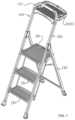
- FIG. 1is a front perspective view depicting a stepladder in accordance with an embodiment of the disclosure with the ladder tray in a use orientation.
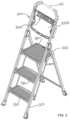
- FIG. 2is a front perspective view depicting the stepladder of FIG. 1 with the ladder tray in a stored orientation.
- FIG. 3is a front elevation view of the stepladder of FIG. 2 .
- FIG. 4is a right orthogonal view of the stepladder of FIG. 2 .
- FIG. 5is a right perspective view of the stepladder of FIG. 2 .
- FIG. 6is a front elevation view of the stepladder of FIG. 1 .
- FIG. 7is a front elevation view of the stepladder of FIG. 1 without the ladder tray.
- FIG. 8is a front elevation view of the stepladder of FIG. 1 without the ladder tray and the ladder tray locking mechanism in the unlocked position.
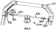
- FIG. 9is a right perspective view of the stepladder of FIG. 8 .
- Stepladder 100has a handle 110 that extends above a ladder tray 200 that may be used to hold tools and materials while using stepladder 100 . It is understood that in place of handle 110 , the frame of stepladder 100 may simply extend above the ladder tray 200 and act as handle 110 .
- Stepladderincludes rails 120 and steps 130 .
- Ladder tray 200is pivotable between an open position as shown in FIG. 1 and a stored position as shown in FIG. 2 .
- the stepladder 100 of the present inventionutilizes a novel locking mechanism 300 to keep ladder tray 200 in the open position.
- Locking mechanism 300preferably has two sliding rods 320 that are biased by springs 330 to a locked position as shown in FIG. 7 . Other means of biasing the rods in the locked position known in the art may also be used.
- Rod ends 325are configured to slide into and out of handle orifices 350 on the handle 110 .
- locking mechanismmay include strike plates 340 . If strike plates 340 are used, it is understood that handle orifices would extend through the strike plates 340 to allow rod ends 325 to slide into and out of locking position.
- Finger grips 310are connected to rods 320 distal the rod ends 325 .
- a usercan press the finger grips 310 together to cause rod ends 325 to withdraw from handle orifices 350 , and allow ladder tray 200 to be pivoted from the open position of FIG. 1 to the stored position of FIG. 2 .
- Ladder tray 200includes ribs 220 to provide strength and stiffness. Pivot pins 210 , located below the handle orifices 350 connect the ladder tray 200 to the handle 110 .
- Rods 320run through rib orifices 230 to provide proper alignment of rods 320 .
- Tray side orifices 240allow rod ends 325 to extend outside of ladder tray 200 and traverse the handle orifices 350 .
- Ladder tray 200also provides a cutout 250 on the side facing a user to allow access to the finger grips 310 .
Landscapes
- Engineering & Computer Science (AREA)
- Mechanical Engineering (AREA)
- Ladders (AREA)
Abstract
Description
Claims (20)
Priority Applications (1)
| Application Number | Priority Date | Filing Date | Title |
|---|---|---|---|
| US16/715,097US11655676B2 (en) | 2018-12-14 | 2019-12-16 | Ladder tray locking mechanism |
Applications Claiming Priority (2)
| Application Number | Priority Date | Filing Date | Title |
|---|---|---|---|
| US201862779633P | 2018-12-14 | 2018-12-14 | |
| US16/715,097US11655676B2 (en) | 2018-12-14 | 2019-12-16 | Ladder tray locking mechanism |
Publications (2)
| Publication Number | Publication Date |
|---|---|
| US20200190905A1 US20200190905A1 (en) | 2020-06-18 |
| US11655676B2true US11655676B2 (en) | 2023-05-23 |
Family
ID=71071341
Family Applications (1)
| Application Number | Title | Priority Date | Filing Date |
|---|---|---|---|
| US16/715,097Active2041-11-12US11655676B2 (en) | 2018-12-14 | 2019-12-16 | Ladder tray locking mechanism |
Country Status (1)
| Country | Link |
|---|---|
| US (1) | US11655676B2 (en) |
Cited By (6)
| Publication number | Priority date | Publication date | Assignee | Title |
|---|---|---|---|---|
| US20230363538A1 (en)* | 2022-05-12 | 2023-11-16 | Jool Products LLC | Foldable locking step stool |
| USD1009304S1 (en)* | 2022-02-07 | 2023-12-26 | Tricam Industries, Inc. | Three-step heavy-duty stepladder |
| USD1009303S1 (en)* | 2022-02-07 | 2023-12-26 | Tricam Industries, Inc. | Two-step heavy-duty stepladder |
| US20240041274A1 (en)* | 2021-04-14 | 2024-02-08 | Michael Cocilova | Toilet Training Step Ladder |
| USD1041033S1 (en)* | 2023-09-26 | 2024-09-03 | Zhejiang Kangqian Industry & Trade Co., Ltd. | Sitting board for ladder |
| USD1095890S1 (en)* | 2024-04-09 | 2025-09-30 | Tricam Industries, Llc | Multi-position ladder bucket |
Families Citing this family (5)
| Publication number | Priority date | Publication date | Assignee | Title |
|---|---|---|---|---|
| WO2020247398A1 (en)* | 2019-06-04 | 2020-12-10 | Wing Enterprises, Incorporated | Step ladder with adjustable tray |
| US12331592B2 (en)* | 2020-12-22 | 2025-06-17 | Tricam Industries, Llc | Deep ladder tray |
| US20220195801A1 (en)* | 2020-12-22 | 2022-06-23 | Spartner Group, Inc. | Rotatable top tray on a stepping structure |
| US20220219611A1 (en)* | 2021-01-13 | 2022-07-14 | Formosa Saint Jose Corp. | Multifunction Ladder Structure |
| USD1005526S1 (en)* | 2023-05-26 | 2023-11-21 | Fuling Ma | Ladder |
Citations (36)
| Publication number | Priority date | Publication date | Assignee | Title |
|---|---|---|---|---|
| US3625388A (en)* | 1969-12-11 | 1971-12-07 | Tray X Corp | Paint tray |
| US3744591A (en)* | 1971-06-25 | 1973-07-10 | Velca Spa | Portable,folding stepladder |
| US4121692A (en)* | 1977-04-04 | 1978-10-24 | Janus Morawski | Ladder tray |
| US4862994A (en)* | 1988-06-22 | 1989-09-05 | Hughes Sr Earl E | Ladder platform |
| US5052581A (en)* | 1990-08-13 | 1991-10-01 | Craft Creations Co., Inc. | Ladder-supported holding tray |
| US5613574A (en)* | 1995-06-23 | 1997-03-25 | Melanson; Charles J. | Ladder mounted tool holster and parts tray |
| US5673885A (en)* | 1995-12-27 | 1997-10-07 | Pham; Paul | Paint tray for a stepladder |
| US5722507A (en)* | 1996-01-11 | 1998-03-03 | Cosco, Inc. | Step stool assembly |
| US5762163A (en)* | 1995-08-29 | 1998-06-09 | Cosco, Inc. | Step stool |
| US6026933A (en)* | 1997-05-29 | 2000-02-22 | Cosco, Inc. | Step stool |
| US6390238B1 (en)* | 1999-08-13 | 2002-05-21 | Cosco Management, Inc. | Foldable step stool with leg lock and handle |
| US6427805B1 (en)* | 1999-01-08 | 2002-08-06 | Cosco Management, Inc. | Folding step stool |
| US6443260B1 (en)* | 1999-12-29 | 2002-09-03 | Ladder Mate Corporation | Step ladder tray |
| US6454050B2 (en)* | 2000-08-11 | 2002-09-24 | Cosco Management, Inc. | Foldable step stool with leg lock and handle |
| US6502664B1 (en)* | 2001-12-21 | 2003-01-07 | Donald Peaker, Sr. | Accessorized stepladder |
| US6536557B2 (en)* | 2001-08-09 | 2003-03-25 | Cosco Management, Inc. | Utility tray for step stool |
| US6550579B2 (en)* | 2000-08-11 | 2003-04-22 | Cosco Management, Inc. | Step stool |
| US7104362B2 (en)* | 2003-08-27 | 2006-09-12 | Cosco Management, Inc. | Foldable step ladder with leg aligner and handle |
| US7108103B2 (en)* | 2003-05-22 | 2006-09-19 | Cosco Management, Inc. | Rigidified step ladder |
| US7159694B2 (en)* | 2004-06-14 | 2007-01-09 | Cosco Management, Inc. | Step stool tray |
| US7182176B2 (en)* | 2004-05-28 | 2007-02-27 | Cosco Management, Inc. | Step stool with elevated tray |
| US20090078504A1 (en)* | 2007-09-26 | 2009-03-26 | Werner Co. | Method and stepladder with a tray |
| USD600820S1 (en)* | 2008-09-03 | 2009-09-22 | Louisville Ladder Inc. | Pail shelf |
| US7849967B2 (en)* | 2006-02-07 | 2010-12-14 | Cosco Management, Inc. | Foldable stepladder with step lock |
| US20110024234A1 (en)* | 2009-07-30 | 2011-02-03 | Chen-Hsiung Lin | Ladder Chair |
| US7931123B2 (en)* | 2004-11-17 | 2011-04-26 | Werner Co. | Stepladder folding twin-step |
| US7963369B2 (en)* | 2007-01-26 | 2011-06-21 | Werner Co. | Step stool and method |
| US7984790B2 (en)* | 2006-06-07 | 2011-07-26 | Cosco Management, Inc. | Folding tray for foldable step stool |
| US8186481B2 (en)* | 2008-03-07 | 2012-05-29 | Wing Enterprises, Inc. | Ladders, ladder components and related methods |
| US8684139B2 (en)* | 2008-11-06 | 2014-04-01 | New-Tec Integration (Xiamen) Co., Ltd. | Step stool |
| US9309718B1 (en)* | 2010-08-05 | 2016-04-12 | Martin Sinclair Matthew | Stable stepladder with utility tray |
| US10138680B2 (en)* | 2015-05-26 | 2018-11-27 | Tricam Industries, Inc. | Hinged tray for ladder or step stool |
| US10221624B2 (en)* | 2013-12-05 | 2019-03-05 | New-Tec Integration (Xiamen) Co., Ltd. | Folding ladder having connecting hinge |
| US10648234B2 (en)* | 2014-03-10 | 2020-05-12 | Tricam Industries, Inc. | Step ladder |
| US20200386050A1 (en)* | 2019-06-04 | 2020-12-10 | Wing Enterprises, Incorporated | Step ladder with adjustable tray |
| US20220195801A1 (en)* | 2020-12-22 | 2022-06-23 | Spartner Group, Inc. | Rotatable top tray on a stepping structure |
- 2019
- 2019-12-16USUS16/715,097patent/US11655676B2/enactiveActive
Patent Citations (38)
| Publication number | Priority date | Publication date | Assignee | Title |
|---|---|---|---|---|
| US3625388A (en)* | 1969-12-11 | 1971-12-07 | Tray X Corp | Paint tray |
| US3744591A (en)* | 1971-06-25 | 1973-07-10 | Velca Spa | Portable,folding stepladder |
| US4121692A (en)* | 1977-04-04 | 1978-10-24 | Janus Morawski | Ladder tray |
| US4862994A (en)* | 1988-06-22 | 1989-09-05 | Hughes Sr Earl E | Ladder platform |
| US5052581A (en)* | 1990-08-13 | 1991-10-01 | Craft Creations Co., Inc. | Ladder-supported holding tray |
| US5613574A (en)* | 1995-06-23 | 1997-03-25 | Melanson; Charles J. | Ladder mounted tool holster and parts tray |
| US5762163A (en)* | 1995-08-29 | 1998-06-09 | Cosco, Inc. | Step stool |
| US5673885A (en)* | 1995-12-27 | 1997-10-07 | Pham; Paul | Paint tray for a stepladder |
| US5722507A (en)* | 1996-01-11 | 1998-03-03 | Cosco, Inc. | Step stool assembly |
| US6026933A (en)* | 1997-05-29 | 2000-02-22 | Cosco, Inc. | Step stool |
| US6427805B1 (en)* | 1999-01-08 | 2002-08-06 | Cosco Management, Inc. | Folding step stool |
| US6390238B1 (en)* | 1999-08-13 | 2002-05-21 | Cosco Management, Inc. | Foldable step stool with leg lock and handle |
| US6443260B1 (en)* | 1999-12-29 | 2002-09-03 | Ladder Mate Corporation | Step ladder tray |
| US6454050B2 (en)* | 2000-08-11 | 2002-09-24 | Cosco Management, Inc. | Foldable step stool with leg lock and handle |
| US6550579B2 (en)* | 2000-08-11 | 2003-04-22 | Cosco Management, Inc. | Step stool |
| US6536557B2 (en)* | 2001-08-09 | 2003-03-25 | Cosco Management, Inc. | Utility tray for step stool |
| US6502664B1 (en)* | 2001-12-21 | 2003-01-07 | Donald Peaker, Sr. | Accessorized stepladder |
| US7108103B2 (en)* | 2003-05-22 | 2006-09-19 | Cosco Management, Inc. | Rigidified step ladder |
| US7104362B2 (en)* | 2003-08-27 | 2006-09-12 | Cosco Management, Inc. | Foldable step ladder with leg aligner and handle |
| US7182176B2 (en)* | 2004-05-28 | 2007-02-27 | Cosco Management, Inc. | Step stool with elevated tray |
| US7159694B2 (en)* | 2004-06-14 | 2007-01-09 | Cosco Management, Inc. | Step stool tray |
| US7931123B2 (en)* | 2004-11-17 | 2011-04-26 | Werner Co. | Stepladder folding twin-step |
| US7849967B2 (en)* | 2006-02-07 | 2010-12-14 | Cosco Management, Inc. | Foldable stepladder with step lock |
| US7984790B2 (en)* | 2006-06-07 | 2011-07-26 | Cosco Management, Inc. | Folding tray for foldable step stool |
| US7963369B2 (en)* | 2007-01-26 | 2011-06-21 | Werner Co. | Step stool and method |
| US20090078504A1 (en)* | 2007-09-26 | 2009-03-26 | Werner Co. | Method and stepladder with a tray |
| US20140054112A1 (en)* | 2007-09-26 | 2014-02-27 | Werner Co. | Method and Stepladder with a Tray |
| US8186481B2 (en)* | 2008-03-07 | 2012-05-29 | Wing Enterprises, Inc. | Ladders, ladder components and related methods |
| US9163455B2 (en)* | 2008-03-07 | 2015-10-20 | Wing Enterprises, Inc. | Ladders, ladder components and related methods |
| USD600820S1 (en)* | 2008-09-03 | 2009-09-22 | Louisville Ladder Inc. | Pail shelf |
| US8684139B2 (en)* | 2008-11-06 | 2014-04-01 | New-Tec Integration (Xiamen) Co., Ltd. | Step stool |
| US20110024234A1 (en)* | 2009-07-30 | 2011-02-03 | Chen-Hsiung Lin | Ladder Chair |
| US9309718B1 (en)* | 2010-08-05 | 2016-04-12 | Martin Sinclair Matthew | Stable stepladder with utility tray |
| US10221624B2 (en)* | 2013-12-05 | 2019-03-05 | New-Tec Integration (Xiamen) Co., Ltd. | Folding ladder having connecting hinge |
| US10648234B2 (en)* | 2014-03-10 | 2020-05-12 | Tricam Industries, Inc. | Step ladder |
| US10138680B2 (en)* | 2015-05-26 | 2018-11-27 | Tricam Industries, Inc. | Hinged tray for ladder or step stool |
| US20200386050A1 (en)* | 2019-06-04 | 2020-12-10 | Wing Enterprises, Incorporated | Step ladder with adjustable tray |
| US20220195801A1 (en)* | 2020-12-22 | 2022-06-23 | Spartner Group, Inc. | Rotatable top tray on a stepping structure |
Cited By (8)
| Publication number | Priority date | Publication date | Assignee | Title |
|---|---|---|---|---|
| US20240041274A1 (en)* | 2021-04-14 | 2024-02-08 | Michael Cocilova | Toilet Training Step Ladder |
| US12264540B2 (en)* | 2021-04-14 | 2025-04-01 | Michael Cocilova | Toilet training step ladder |
| USD1009304S1 (en)* | 2022-02-07 | 2023-12-26 | Tricam Industries, Inc. | Three-step heavy-duty stepladder |
| USD1009303S1 (en)* | 2022-02-07 | 2023-12-26 | Tricam Industries, Inc. | Two-step heavy-duty stepladder |
| US20230363538A1 (en)* | 2022-05-12 | 2023-11-16 | Jool Products LLC | Foldable locking step stool |
| US12419421B2 (en)* | 2022-05-12 | 2025-09-23 | Jool Products, LLC | Foldable locking step stool |
| USD1041033S1 (en)* | 2023-09-26 | 2024-09-03 | Zhejiang Kangqian Industry & Trade Co., Ltd. | Sitting board for ladder |
| USD1095890S1 (en)* | 2024-04-09 | 2025-09-30 | Tricam Industries, Llc | Multi-position ladder bucket |
Also Published As
| Publication number | Publication date |
|---|---|
| US20200190905A1 (en) | 2020-06-18 |
Similar Documents
| Publication | Publication Date | Title |
|---|---|---|
| US11655676B2 (en) | Ladder tray locking mechanism | |
| US11788351B2 (en) | Ladders, ladder components and related methods | |
| US10138680B2 (en) | Hinged tray for ladder or step stool | |
| US20240392627A1 (en) | Stepladder tray | |
| US7128187B2 (en) | Stepladder with pivoting utility tray | |
| US10093017B2 (en) | Sawhorse | |
| US20070181369A1 (en) | Foldable stepladder with step lock | |
| US12331592B2 (en) | Deep ladder tray | |
| CN114207243A (en) | Stepladder with adjustable tray | |
| CN110891461A (en) | Ladder hinge and ladder incorporating same | |
| US11505994B2 (en) | Top cap for multi-position ladder | |
| GB2467004A (en) | A ladder | |
| US20240151107A1 (en) | Multi-position ladder bucket | |
| US20250172042A1 (en) | Combination ladder and hinge mechanism |
Legal Events
| Date | Code | Title | Description |
|---|---|---|---|
| FEPP | Fee payment procedure | Free format text:ENTITY STATUS SET TO UNDISCOUNTED (ORIGINAL EVENT CODE: BIG.); ENTITY STATUS OF PATENT OWNER: SMALL ENTITY | |
| FEPP | Fee payment procedure | Free format text:ENTITY STATUS SET TO SMALL (ORIGINAL EVENT CODE: SMAL); ENTITY STATUS OF PATENT OWNER: SMALL ENTITY | |
| STPP | Information on status: patent application and granting procedure in general | Free format text:APPLICATION DISPATCHED FROM PREEXAM, NOT YET DOCKETED | |
| AS | Assignment | Owner name:TRICAM INDUSTRIES, INC., MINNESOTA Free format text:ASSIGNMENT OF ASSIGNORS INTEREST;ASSIGNOR:FOLEY, JOSEPH P.;REEL/FRAME:051580/0710 Effective date:20191230 | |
| STPP | Information on status: patent application and granting procedure in general | Free format text:DOCKETED NEW CASE - READY FOR EXAMINATION | |
| STPP | Information on status: patent application and granting procedure in general | Free format text:NON FINAL ACTION MAILED | |
| STPP | Information on status: patent application and granting procedure in general | Free format text:RESPONSE TO NON-FINAL OFFICE ACTION ENTERED AND FORWARDED TO EXAMINER | |
| STCF | Information on status: patent grant | Free format text:PATENTED CASE | |
| AS | Assignment | Owner name:JPMORGAN CHASE BANK, N.A., ILLINOIS Free format text:SECURITY INTEREST;ASSIGNOR:TRICAM INDUSTRIES, LLC;REEL/FRAME:070082/0930 Effective date:20250131 | |
| AS | Assignment | Owner name:TRICAM INDUSTRIES, LLC, MINNESOTA Free format text:CERTIFICATE OF CONVERSION;ASSIGNOR:TRICAM INDUSTRIES, INC.;REEL/FRAME:070144/0480 Effective date:20250124 |