US11654224B2 - Methods and devices for percutaneous implantation of arterio-venous grafts - Google Patents
Methods and devices for percutaneous implantation of arterio-venous graftsDownload PDFInfo
- Publication number
- US11654224B2 US11654224B2US15/855,672US201715855672AUS11654224B2US 11654224 B2US11654224 B2US 11654224B2US 201715855672 AUS201715855672 AUS 201715855672AUS 11654224 B2US11654224 B2US 11654224B2
- Authority
- US
- United States
- Prior art keywords
- stylet
- graft
- catheter
- access
- guide tube
- Prior art date
- Legal status (The legal status is an assumption and is not a legal conclusion. Google has not performed a legal analysis and makes no representation as to the accuracy of the status listed.)
- Active, expires
Links
- 238000000034methodMethods0.000titleabstractdescription27
- 238000002513implantationMethods0.000titleabstractdescription10
- 238000001631haemodialysisMethods0.000claimsabstractdescription14
- 230000000322hemodialysisEffects0.000claimsabstractdescription14
- 210000002048axillary veinAnatomy0.000claimsdescription30
- 210000002302brachial arteryAnatomy0.000claimsdescription30
- 210000003462veinAnatomy0.000claimsdescription11
- 210000001367arteryAnatomy0.000claimsdescription10
- 238000007920subcutaneous administrationMethods0.000claimsdescription8
- 230000003872anastomosisEffects0.000claimsdescription5
- 230000005641tunnelingEffects0.000claimsdescription5
- 230000001154acute effectEffects0.000claims1
- 230000002792vascularEffects0.000abstractdescription16
- 238000011282treatmentMethods0.000abstractdescription7
- 208000001647Renal InsufficiencyDiseases0.000abstractdescription5
- 201000006370kidney failureDiseases0.000abstractdescription5
- 210000005166vasculatureAnatomy0.000description21
- 239000000463materialSubstances0.000description11
- 206010033675panniculitisDiseases0.000description10
- 210000004304subcutaneous tissueAnatomy0.000description10
- 210000003191femoral veinAnatomy0.000description8
- 230000007246mechanismEffects0.000description7
- 210000001519tissueAnatomy0.000description7
- 210000005249arterial vasculatureAnatomy0.000description6
- 210000001105femoral arteryAnatomy0.000description6
- 230000000149penetrating effectEffects0.000description6
- 206010003226Arteriovenous fistulaDiseases0.000description5
- 210000002414legAnatomy0.000description5
- 229910001000nickel titaniumInorganic materials0.000description5
- 238000004891communicationMethods0.000description4
- 238000002594fluoroscopyMethods0.000description4
- 239000003550markerSubstances0.000description4
- 229910052751metalInorganic materials0.000description4
- 239000002184metalSubstances0.000description4
- 210000000689upper legAnatomy0.000description4
- 210000004369bloodAnatomy0.000description3
- 239000008280bloodSubstances0.000description3
- 230000006835compressionEffects0.000description3
- 238000007906compressionMethods0.000description3
- 238000003384imaging methodMethods0.000description3
- 239000007943implantSubstances0.000description3
- 206010002091AnaesthesiaDiseases0.000description2
- HZEWFHLRYVTOIW-UHFFFAOYSA-N[Ti].[Ni]Chemical compound[Ti].[Ni]HZEWFHLRYVTOIW-UHFFFAOYSA-N0.000description2
- 230000037005anaesthesiaEffects0.000description2
- 210000002376aorta thoracicAnatomy0.000description2
- 230000017531blood circulationEffects0.000description2
- 238000000502dialysisMethods0.000description2
- 238000006073displacement reactionMethods0.000description2
- 229920000295expanded polytetrafluoroethylenePolymers0.000description2
- 239000012530fluidSubstances0.000description2
- 238000003780insertionMethods0.000description2
- 230000037431insertionEffects0.000description2
- 230000003993interactionEffects0.000description2
- HLXZNVUGXRDIFK-UHFFFAOYSA-Nnickel titaniumChemical compound[Ti].[Ti].[Ti].[Ti].[Ti].[Ti].[Ti].[Ti].[Ti].[Ti].[Ti].[Ni].[Ni].[Ni].[Ni].[Ni].[Ni].[Ni].[Ni].[Ni].[Ni].[Ni].[Ni].[Ni].[Ni]HLXZNVUGXRDIFK-UHFFFAOYSA-N0.000description2
- 239000004033plasticSubstances0.000description2
- 229920003023plasticPolymers0.000description2
- BASFCYQUMIYNBI-UHFFFAOYSA-NplatinumChemical compound[Pt]BASFCYQUMIYNBI-UHFFFAOYSA-N0.000description2
- 239000010935stainless steelSubstances0.000description2
- 229910001220stainless steelInorganic materials0.000description2
- 238000003466weldingMethods0.000description2
- 241000283690Bos taurusSpecies0.000description1
- 206010039897SedationDiseases0.000description1
- 208000007536ThrombosisDiseases0.000description1
- 238000004026adhesive bondingMethods0.000description1
- 210000003484anatomyAnatomy0.000description1
- 238000002399angioplastyMethods0.000description1
- 230000009286beneficial effectEffects0.000description1
- 230000008901benefitEffects0.000description1
- 230000015572biosynthetic processEffects0.000description1
- 210000004204blood vesselAnatomy0.000description1
- 210000001715carotid arteryAnatomy0.000description1
- 238000013461designMethods0.000description1
- 238000005530etchingMethods0.000description1
- 239000000835fiberSubstances0.000description1
- 210000000245forearmAnatomy0.000description1
- PCHJSUWPFVWCPO-UHFFFAOYSA-NgoldChemical compound[Au]PCHJSUWPFVWCPO-UHFFFAOYSA-N0.000description1
- 229910052737goldInorganic materials0.000description1
- 239000010931goldSubstances0.000description1
- 210000004731jugular veinAnatomy0.000description1
- 238000003698laser cuttingMethods0.000description1
- 239000003589local anesthetic agentSubstances0.000description1
- 238000012986modificationMethods0.000description1
- 230000004048modificationEffects0.000description1
- RVTZCBVAJQQJTK-UHFFFAOYSA-Noxygen(2-);zirconium(4+)Chemical compound[O-2].[O-2].[Zr+4]RVTZCBVAJQQJTK-UHFFFAOYSA-N0.000description1
- 229910052697platinumInorganic materials0.000description1
- HWLDNSXPUQTBOD-UHFFFAOYSA-Nplatinum-iridium alloyChemical compound[Ir].[Pt]HWLDNSXPUQTBOD-UHFFFAOYSA-N0.000description1
- 229920001343polytetrafluoroethylenePolymers0.000description1
- 239000004810polytetrafluoroethyleneSubstances0.000description1
- 229920002635polyurethanePolymers0.000description1
- 239000004814polyurethaneSubstances0.000description1
- 230000036280sedationEffects0.000description1
- 210000003270subclavian arteryAnatomy0.000description1
- 210000001321subclavian veinAnatomy0.000description1
- 239000003053toxinSubstances0.000description1
- 231100000765toxinToxicity0.000description1
- 108700012359toxinsProteins0.000description1
- 238000002604ultrasonographyMethods0.000description1
- 210000001631vena cava inferiorAnatomy0.000description1
- 210000002620vena cava superiorAnatomy0.000description1
Images


Classifications
- A—HUMAN NECESSITIES
- A61—MEDICAL OR VETERINARY SCIENCE; HYGIENE
- A61M—DEVICES FOR INTRODUCING MEDIA INTO, OR ONTO, THE BODY; DEVICES FOR TRANSDUCING BODY MEDIA OR FOR TAKING MEDIA FROM THE BODY; DEVICES FOR PRODUCING OR ENDING SLEEP OR STUPOR
- A61M1/00—Suction or pumping devices for medical purposes; Devices for carrying-off, for treatment of, or for carrying-over, body-liquids; Drainage systems
- A61M1/36—Other treatment of blood in a by-pass of the natural circulatory system, e.g. temperature adaptation, irradiation ; Extra-corporeal blood circuits
- A61M1/3621—Extra-corporeal blood circuits
- A61M1/3653—Interfaces between patient blood circulation and extra-corporal blood circuit
- A61M1/3655—Arterio-venous shunts or fistulae
- A—HUMAN NECESSITIES
- A61—MEDICAL OR VETERINARY SCIENCE; HYGIENE
- A61B—DIAGNOSIS; SURGERY; IDENTIFICATION
- A61B17/00—Surgical instruments, devices or methods
- A61B17/11—Surgical instruments, devices or methods for performing anastomosis; Buttons for anastomosis
- A—HUMAN NECESSITIES
- A61—MEDICAL OR VETERINARY SCIENCE; HYGIENE
- A61B—DIAGNOSIS; SURGERY; IDENTIFICATION
- A61B17/00—Surgical instruments, devices or methods
- A61B17/34—Trocars; Puncturing needles
- A61B17/3415—Trocars; Puncturing needles for introducing tubes or catheters, e.g. gastrostomy tubes, drain catheters
- A—HUMAN NECESSITIES
- A61—MEDICAL OR VETERINARY SCIENCE; HYGIENE
- A61F—FILTERS IMPLANTABLE INTO BLOOD VESSELS; PROSTHESES; DEVICES PROVIDING PATENCY TO, OR PREVENTING COLLAPSING OF, TUBULAR STRUCTURES OF THE BODY, e.g. STENTS; ORTHOPAEDIC, NURSING OR CONTRACEPTIVE DEVICES; FOMENTATION; TREATMENT OR PROTECTION OF EYES OR EARS; BANDAGES, DRESSINGS OR ABSORBENT PADS; FIRST-AID KITS
- A61F2/00—Filters implantable into blood vessels; Prostheses, i.e. artificial substitutes or replacements for parts of the body; Appliances for connecting them with the body; Devices providing patency to, or preventing collapsing of, tubular structures of the body, e.g. stents
- A61F2/02—Prostheses implantable into the body
- A61F2/04—Hollow or tubular parts of organs, e.g. bladders, tracheae, bronchi or bile ducts
- A61F2/06—Blood vessels
- A61F2/064—Blood vessels with special features to facilitate anastomotic coupling
- A—HUMAN NECESSITIES
- A61—MEDICAL OR VETERINARY SCIENCE; HYGIENE
- A61F—FILTERS IMPLANTABLE INTO BLOOD VESSELS; PROSTHESES; DEVICES PROVIDING PATENCY TO, OR PREVENTING COLLAPSING OF, TUBULAR STRUCTURES OF THE BODY, e.g. STENTS; ORTHOPAEDIC, NURSING OR CONTRACEPTIVE DEVICES; FOMENTATION; TREATMENT OR PROTECTION OF EYES OR EARS; BANDAGES, DRESSINGS OR ABSORBENT PADS; FIRST-AID KITS
- A61F2/00—Filters implantable into blood vessels; Prostheses, i.e. artificial substitutes or replacements for parts of the body; Appliances for connecting them with the body; Devices providing patency to, or preventing collapsing of, tubular structures of the body, e.g. stents
- A61F2/02—Prostheses implantable into the body
- A61F2/04—Hollow or tubular parts of organs, e.g. bladders, tracheae, bronchi or bile ducts
- A61F2/06—Blood vessels
- A61F2/07—Stent-grafts
- A—HUMAN NECESSITIES
- A61—MEDICAL OR VETERINARY SCIENCE; HYGIENE
- A61F—FILTERS IMPLANTABLE INTO BLOOD VESSELS; PROSTHESES; DEVICES PROVIDING PATENCY TO, OR PREVENTING COLLAPSING OF, TUBULAR STRUCTURES OF THE BODY, e.g. STENTS; ORTHOPAEDIC, NURSING OR CONTRACEPTIVE DEVICES; FOMENTATION; TREATMENT OR PROTECTION OF EYES OR EARS; BANDAGES, DRESSINGS OR ABSORBENT PADS; FIRST-AID KITS
- A61F2/00—Filters implantable into blood vessels; Prostheses, i.e. artificial substitutes or replacements for parts of the body; Appliances for connecting them with the body; Devices providing patency to, or preventing collapsing of, tubular structures of the body, e.g. stents
- A61F2/95—Instruments specially adapted for placement or removal of stents or stent-grafts
- A61F2/962—Instruments specially adapted for placement or removal of stents or stent-grafts having an outer sleeve
- A61F2/966—Instruments specially adapted for placement or removal of stents or stent-grafts having an outer sleeve with relative longitudinal movement between outer sleeve and prosthesis, e.g. using a push rod
- A—HUMAN NECESSITIES
- A61—MEDICAL OR VETERINARY SCIENCE; HYGIENE
- A61M—DEVICES FOR INTRODUCING MEDIA INTO, OR ONTO, THE BODY; DEVICES FOR TRANSDUCING BODY MEDIA OR FOR TAKING MEDIA FROM THE BODY; DEVICES FOR PRODUCING OR ENDING SLEEP OR STUPOR
- A61M25/00—Catheters; Hollow probes
- A61M25/01—Introducing, guiding, advancing, emplacing or holding catheters
- A61M25/0102—Insertion or introduction using an inner stiffening member, e.g. stylet or push-rod
- A—HUMAN NECESSITIES
- A61—MEDICAL OR VETERINARY SCIENCE; HYGIENE
- A61M—DEVICES FOR INTRODUCING MEDIA INTO, OR ONTO, THE BODY; DEVICES FOR TRANSDUCING BODY MEDIA OR FOR TAKING MEDIA FROM THE BODY; DEVICES FOR PRODUCING OR ENDING SLEEP OR STUPOR
- A61M25/00—Catheters; Hollow probes
- A61M25/01—Introducing, guiding, advancing, emplacing or holding catheters
- A61M25/0194—Tunnelling catheters
- A—HUMAN NECESSITIES
- A61—MEDICAL OR VETERINARY SCIENCE; HYGIENE
- A61M—DEVICES FOR INTRODUCING MEDIA INTO, OR ONTO, THE BODY; DEVICES FOR TRANSDUCING BODY MEDIA OR FOR TAKING MEDIA FROM THE BODY; DEVICES FOR PRODUCING OR ENDING SLEEP OR STUPOR
- A61M25/00—Catheters; Hollow probes
- A61M25/01—Introducing, guiding, advancing, emplacing or holding catheters
- A61M25/06—Body-piercing guide needles or the like
- A61M25/0662—Guide tubes
- A—HUMAN NECESSITIES
- A61—MEDICAL OR VETERINARY SCIENCE; HYGIENE
- A61M—DEVICES FOR INTRODUCING MEDIA INTO, OR ONTO, THE BODY; DEVICES FOR TRANSDUCING BODY MEDIA OR FOR TAKING MEDIA FROM THE BODY; DEVICES FOR PRODUCING OR ENDING SLEEP OR STUPOR
- A61M25/00—Catheters; Hollow probes
- A61M25/01—Introducing, guiding, advancing, emplacing or holding catheters
- A61M25/09—Guide wires
- A61M25/09041—Mechanisms for insertion of guide wires
- A—HUMAN NECESSITIES
- A61—MEDICAL OR VETERINARY SCIENCE; HYGIENE
- A61B—DIAGNOSIS; SURGERY; IDENTIFICATION
- A61B17/00—Surgical instruments, devices or methods
- A61B17/11—Surgical instruments, devices or methods for performing anastomosis; Buttons for anastomosis
- A61B2017/1107—Surgical instruments, devices or methods for performing anastomosis; Buttons for anastomosis for blood vessels
- A—HUMAN NECESSITIES
- A61—MEDICAL OR VETERINARY SCIENCE; HYGIENE
- A61B—DIAGNOSIS; SURGERY; IDENTIFICATION
- A61B17/00—Surgical instruments, devices or methods
- A61B17/11—Surgical instruments, devices or methods for performing anastomosis; Buttons for anastomosis
- A61B2017/1135—End-to-side connections, e.g. T- or Y-connections
- A—HUMAN NECESSITIES
- A61—MEDICAL OR VETERINARY SCIENCE; HYGIENE
- A61F—FILTERS IMPLANTABLE INTO BLOOD VESSELS; PROSTHESES; DEVICES PROVIDING PATENCY TO, OR PREVENTING COLLAPSING OF, TUBULAR STRUCTURES OF THE BODY, e.g. STENTS; ORTHOPAEDIC, NURSING OR CONTRACEPTIVE DEVICES; FOMENTATION; TREATMENT OR PROTECTION OF EYES OR EARS; BANDAGES, DRESSINGS OR ABSORBENT PADS; FIRST-AID KITS
- A61F2/00—Filters implantable into blood vessels; Prostheses, i.e. artificial substitutes or replacements for parts of the body; Appliances for connecting them with the body; Devices providing patency to, or preventing collapsing of, tubular structures of the body, e.g. stents
- A61F2/02—Prostheses implantable into the body
- A61F2/04—Hollow or tubular parts of organs, e.g. bladders, tracheae, bronchi or bile ducts
- A61F2/06—Blood vessels
- A61F2/07—Stent-grafts
- A61F2002/072—Encapsulated stents, e.g. wire or whole stent embedded in lining
- A—HUMAN NECESSITIES
- A61—MEDICAL OR VETERINARY SCIENCE; HYGIENE
- A61M—DEVICES FOR INTRODUCING MEDIA INTO, OR ONTO, THE BODY; DEVICES FOR TRANSDUCING BODY MEDIA OR FOR TAKING MEDIA FROM THE BODY; DEVICES FOR PRODUCING OR ENDING SLEEP OR STUPOR
- A61M25/00—Catheters; Hollow probes
- A61M25/0067—Catheters; Hollow probes characterised by the distal end, e.g. tips
- A61M25/0082—Catheter tip comprising a tool
- A61M2025/0095—Catheter tip comprising a tool being one or more needles protruding from the distal tip and which are not used for injection nor for electro-stimulation, e.g. for fixation purposes
- A—HUMAN NECESSITIES
- A61—MEDICAL OR VETERINARY SCIENCE; HYGIENE
- A61M—DEVICES FOR INTRODUCING MEDIA INTO, OR ONTO, THE BODY; DEVICES FOR TRANSDUCING BODY MEDIA OR FOR TAKING MEDIA FROM THE BODY; DEVICES FOR PRODUCING OR ENDING SLEEP OR STUPOR
- A61M25/00—Catheters; Hollow probes
- A61M25/01—Introducing, guiding, advancing, emplacing or holding catheters
- A61M25/0194—Tunnelling catheters
- A61M2025/0197—Tunnelling catheters for creating an artificial passage within the body, e.g. in order to go around occlusions
- A—HUMAN NECESSITIES
- A61—MEDICAL OR VETERINARY SCIENCE; HYGIENE
- A61M—DEVICES FOR INTRODUCING MEDIA INTO, OR ONTO, THE BODY; DEVICES FOR TRANSDUCING BODY MEDIA OR FOR TAKING MEDIA FROM THE BODY; DEVICES FOR PRODUCING OR ENDING SLEEP OR STUPOR
- A61M2205/00—General characteristics of the apparatus
- A61M2205/02—General characteristics of the apparatus characterised by a particular materials
- A61M2205/0266—Shape memory materials
- A—HUMAN NECESSITIES
- A61—MEDICAL OR VETERINARY SCIENCE; HYGIENE
- A61M—DEVICES FOR INTRODUCING MEDIA INTO, OR ONTO, THE BODY; DEVICES FOR TRANSDUCING BODY MEDIA OR FOR TAKING MEDIA FROM THE BODY; DEVICES FOR PRODUCING OR ENDING SLEEP OR STUPOR
- A61M25/00—Catheters; Hollow probes
- A61M25/01—Introducing, guiding, advancing, emplacing or holding catheters
- A61M25/0105—Steering means as part of the catheter or advancing means; Markers for positioning
- A61M25/0108—Steering means as part of the catheter or advancing means; Markers for positioning using radio-opaque or ultrasound markers
Definitions
- the present disclosurerelates to devices and methods for vascular access, including the treatment of patients with renal failure. More specifically, in some embodiments, the present disclosure relates to devices and methods that provide vascular access to treat patients with kidney failure, including percutaneous implantation of arterio-venous grafts.
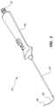
- FIG. 1is a perspective view of an access device.
- FIG. 2 Ais a side view of a cross-section of a portion of the access device of FIG. 1 in a first configuration with an extended guide tube and stylet, the access device comprising a ramped surface.
- FIG. 2 Bis a side view of a cross-section of a portion of the access device of FIG. 1 in a second configuration with a retracted guide tube and stylet, the access device comprising a ramped surface.
- FIG. 3 Ais a side view of a cross-section of a portion of another embodiment of an access device in a first configuration with an extended guide tube and stylet.
- FIG. 3 Bis a side view of a cross-section of a portion of the access device of FIG. 3 A in a second configuration with a retracted guide tube and stylet.
- FIG. 4 Ais a bottom view of the access device of FIG. 1 with a portion of the handle removed to show internal components.
- FIG. 4 Bis a perspective view of a top portion of the handle and other components of the access device of FIG. 1 configured with the guide tube and stylet advanced.
- FIG. 4 Cis a perspective view of a bottom portion of the handle of the access device of FIG. 1 .
- FIG. 5 Ais a side view of the access device of FIG. 1 prior to advancement of the guide tube.
- FIG. 5 Bis a side view of the access device of FIG. 1 following deployment of the guide tube and loading of a spring loading mechanism.
- FIG. 5 Cis a side view of the access device of FIG. 1 following deployment of the stylet.
- FIG. 6 Ais a perspective view of an arterio-venousgraft.
- FIG. 6 Bis a perspective view of an end of the arterio-venous graft of FIG. 6 A .
- FIG. 6 Cis a cross-sectional view of a portion of the arterio-venous graft of FIG. 6 A coupled to a vessel.
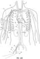
- FIG. 7is a schematic, cross-sectional view of arterial and venous vasculatures of a patient illustrating guidewires within the arterial and venous vasculatures.
- FIG. 8 Ais a schematic cross-sectional view of arterial and venous vasculatures of the patient illustrating first and second access catheters of the access device of FIG. 1 within the brachial artery and the axillary vein respectively.
- FIG. 8 Bis a schematic cross-sectional view of the arterial and venous vasculature of the patient's upper right arm illustrating first and second access catheters of the access device of FIG. 1 within the brachial artery and the axillary vein respectively.
- FIG. 9 Ais a schematic cross-sectional view of arterial and venous vasculatures of the patient illustrating first and second access catheters of the access device of FIG. 1 within the brachial artery and the axillary vein respectively and first and second stylets penetrating a wall of the brachial artery and a wall of the axillary vein respectively.
- FIG. 9 Bis a schematic cross-sectional view of the arterial and venous vasculature of the patient's right arm illustrating first and second access catheters of the access device of FIG. 1 within the brachial artery and the axillary vein respectively, and first and second stylets penetrating a wall of the brachial artery and a wall of the axillary vein respectively.
- FIG. 10 Ais a schematic cross-sectional view of arterial and venous vasculatures of the patient illustrating first and second stylets of the access device of FIG. 1 penetrating the wall of the brachial artery and penetrating the wall of the axillary vein, respectively, with first and second access catheters removed
- FIG. 10 Bis a schematic cross-sectional view of the arterial and venous vasculature of the patient's right arm illustrating first and second stylets of the access device of FIG. 1 penetrating the wall of the brachial artery to form an arterial exit site and penetrating the wall of the axillary vein to form a venous exit site, respectively, with first and second access catheters removed.
- FIG. 11 Ais a schematic cross-sectional view of arterial and venous vasculatures of the patient illustrating a subcutaneous tunnel between the arterial exit site and the venous exit site.
- FIG. 11 Bis a schematic cross-sectional view of the arterial and venous vasculature of the patient's right arm illustrating a subcutaneous tunnel between the arterial exit site and the venous exit site.
- FIG. 12 Ais a schematic cross-sectional view of arterial and venous vasculatures of the patient illustrating the first stylet of the device of FIG. 1 forming a loop through a patient's arterial vasculature, through the subcutaneous tunnel, and through the patient's venous vasculature.
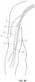
- FIG. 12 Bis a schematic cross-sectional view of the arterial and venous vasculature of the patient's right arm illustrating the first stylet of the access device of FIG. 1 forming a loop through the brachial artery, through the subcutaneous tunnel, and through the axillary vein.
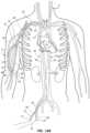
- FIG. 13 Ais a schematic cross-sectional view of arterial and venous vasculatures of the patient illustrating the arterio-venous graft of FIG. 6 A implanted in the arm.
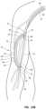
- FIG. 13 Bis a schematic cross-sectional view of the arterial and venous vasculature of the patient's right arm illustrating the arterio-venous graft of FIG. 6 A implanted in the arm.
- Vascular access for hemodialysis treatment of kidney failure patientsis the lifeline of the patient. Hemodialysis treatment requires access to a patient's vasculature three times a week.
- Vascular access typesinclude arterio-venous fistula (AVF), arterio-venous graft (AVG) and center venous hemodialysis catheter.
- AVFarterio-venous fistula
- AVGarterio-venous graft
- the AVFmay be beneficial in many instances as it utilizes autogenous vessels. However, the AVF is not suitable for every patient and creation of an AVF requires a surgeon and anesthesia.
- the AVGis a synthetic graft connecting an artery to a vein. The AVG is normally implanted by a surgeon. However, percutaneous techniques and devices allow for non-surgeons, such as interventionalists, to implant the AVG, reducing the invasiveness of the procedure and potentially reducing procedural costs.
- the present disclosuredescribes access devices and methods for providing a second entry point to a vessel, the second entry point remote from a first entry point.
- the access devices and methods of the present disclosuremay be used to create a vascular access for hemodialysis by percutaneous implantation of a graft.
- access devices within the scope of this disclosureinclude, systems comprising: a vascular catheter having first and second lumens, the first lumen being adapted to receive a vascular guidewire; a guide tube disposed in the second lumen, the guide tube having a distal end with a preformed curve; a stylet disposed in the guide tube, the stylet having a sharp distal tip configured to pierce tissue; a guide tube actuator operatively connected to the guide tube or vascular catheter, the guide tube actuator configured to produce relative movement between the guide tube and the vascular catheter; and a stylet actuator operatively connected to the stylet, the stylet actuator having a stylet advancement mechanism, Access devices within the scope of this disclosure may provide a system for accessing an artery and a vein at second sites beyond initial entry sites into the artery and vein and forming a blood flow lumen through subcutaneous space along between the second access sites of the artery and vein.
- Coupled toand “in communication with” refer to any form of interaction between two or more entities, including mechanical, electrical, magnetic, electromagnetic, fluid, and thermal interaction.
- Two componentsmay be coupled to or in communication with each other even though they are not in direct contact with each other.
- two componentsmay be coupled to or in communication with each other through an intermediate component.
- distal and proximalare given their ordinary meaning in the art. That is, the distal end of a medical device means the end of the device furthest from the practitioner during normal use.
- the proximal endrefers to the opposite end, or the end nearest the practitioner during use.
- the proximal end of the access devicerefers to the end nearest the handle and the distal end refers to the opposite end, the end nearest the tip of the catheter.
- proximal endalways refers to the handle end of the access device (even if the distal end is temporarily closer to the physician).
- FIGS. 1 - 5 Cshow various embodiments of devices for percutaneously implanting a graft.
- the devices disclosed in FIGS. 1 - 5 Cmay be used in implanting an artereo-venous graft for hemodialysis.
- the devices shown in FIGS. 1 - 5 C and described in the present disclosureinclude certain features of those shown in U.S. Pat. No. 9,220,874, the disclosure of which is incorporated herein by reference. As indicated above, FIGS. 1 - 5 C are not necessarily drawn to scale.
- an access device 10may comprise a vascular access catheter or first catheter 42 , a handle or an actuator 44 , a guide tube or cover tube 60 , and a stylet 58 .
- the access catheter 42may be coupled to and extend from the handle 44 .
- the length and diameter of the access catheter 42may depend on a treatment or anatomy for which the access catheter 42 is intended for use.
- the length of the access catheter 42may be configured to traverse the distance between a desired entry point into an artery and the location of an occluded portion of the artery.
- the length of the access catheter 42may range from 20 cm to 150 cm, including from 50 cm to 100 cm.
- the diameter of the access catheter 42may range from 5 Fr to 9. Fr, including from 6 Fr to 8. Fr.
- FIGS. 2 A- 3 Bwhich illustrate a portion of the access device 10 comprising a distal portion of the access catheter 42 in FIGS. 2 A and 2 B and an analogous portion of an alternative embodiment of an access catheter 63 in FIGS. 3 A and 3 B .
- the access catheters 42 and 63are shown in cross-section, while the elements disposed within the access catheters 42 and 63 are not in cross-section for clarity.
- the access catheter 63 of FIGS. 3 A and 3 Bis identical to access the catheter 42 of FIGS. 2 A and 2 B except that access catheter 63 does not comprise a ramped surface as further detailed below. Accordingly, other elements of the access device 10 of FIG. 1 as shown in FIGS.
- FIGS. 3 A and 3 B(such as a guidewire 30 ) retain the same numerals as the embodiment of FIGS. 1 , 2 A and 2 B . Disclosure recited in connection with the access catheter 42 of FIGS. 2 A and 2 B may be analogously applied to the access catheter 63 of FIGS. 3 A and 3 B .
- the access catheter 42may comprise a guidewire lumen 46 and a stylet lumen 50 .
- the guidewire lumen 46 and the stylet lumen 50may be configured as a single lumen.
- the guidewire lumen 46may be sized to receive any suitably sized guidewire, such as 0.014 inch, 0.018 inch, 0.035 inch, etc.
- the guidewire lumen 46may be configured as a rapid exchange (RX) guidewire lumen for receiving the guidewire 30 .
- the guidewire lumen 46may comprise a port adjacent a proximal portion that is configured to receive the guidewire 30 .
- a wall of the guidewire lumen 46may be slit adjacent the proximal portion such that the guidewire 30 can be slipped into the guidewire lumen 46 via the slit.
- the guidewire lumen 46may extend to a proximal end of the access catheter 42 and the guidewire 30 may be advanced through a port (not shown) of the handle 44 into the guidewire lumen 46 .
- the guidewire 30can be introduced into the guidewire lumen 46 using an introducer kit (not shown).
- the stylet lumen 50may extend from the handle 44 to an opening 54 adjacent the distal end of the access catheter 42 .
- the stylet lumen 50curves or is ramped at its distal end to form a camming surface 56 as shown in the embodiment of FIGS. 2 A and 2 B .
- the camming surface 56can provide additional structural support and curving guidance to the guide tube 60 when the guide tube 60 is advanced into an extended position.
- the stylet lumen 50does not have a curved camming surface.
- the stylet lumen 50can be substantially straight adjacent its distal end as illustrated in the embodiment of FIGS. 3 A and 3 B .
- the access catheter 42comprises a catheter tip 47 at the distal end of the access catheter 42 .
- the catheter tip 47may be tapered, beveled, or conical, or comprise other shapes or structures.
- the catheter tip 47includes a radiopaque marker configured to be visible under fluoroscopy.
- the radiopaque markercan be embedded in the catheter tip 47 .
- the shape of the radiopaque markercan be selected to facilitate fluoroscopic identification of the location and orientation of the catheter tip 47 . Examples of radiopaque marker materials include gold, platinum, platinum-iridium, and other biocompatible radiopaque materials.
- the guide tube 60may be concentrically disposed within the stylet lumen 50 of the access catheter 42 .
- the guide tube 60may be operatively coupled to the handle 44 and extend from the handle 44 toward the distal end of the access catheter 42 .
- a distal end of the guide tube 60may be positioned adjacent the catheter tip 47 prior to actuation of the handle 44 as illustrated in the configurations of FIGS. 2 B and 3 B .
- the guide tube 60may extend beyond the catheter tip 47 following actuation of the handle 44 , such as in the configurations shown in FIGS. 2 A and 3 A .
- the guide tube 60may not extend beyond the catheter tip 47 following actuation of the handle 44 , such as embodiments wherein the stylet 58 extends beyond the catheter tip 47 (as further detailed below) but the guide tube 60 remains within the stylet lumen 50 after actuation.
- the guide tube 60comprises a preformed curve or bend of substantially 90 degrees at the distal end of the guide tube 60 .
- the range of the angle of the curve or bendmay be from 15 degrees to 120 degrees, including 75 degrees to 105 degrees.
- the camming surface 56 of the stylet lumen 50can promote the curvature of the guide tube 60 .
- the guide tube 60may be formed of any suitable material such as nickel titanium, shape memory metal, superelastic metal, stainless steel, thermal plastic, etc.
- the outside diameter of the guide tube 60may be configured such that the guide tube 60 can be slidably disposed within the stylet lumen 50 .
- the inside diameter of the guide tube 60may be configured such that the stylet 58 can be slidably disposed within the guide tube 60 .
- the guide tube 60may be a nitinol hypotube having an outer diameter of 0.025 inch and an inside diameter greater than 0.014 inch such that an 0.014 inch diameter stylet can be disposed with the guide tube 60 .
- the stylet 58may be concentrically disposed within the guide tube 60 .
- the stylet 58may be operatively coupled to the handle 44 and extend from the handle 44 toward the distal end of the access catheter 42 .
- a distal end of the stylet 58may be positioned adjacent the distal end of the guide tube 60 prior to actuation of the handle 44 as illustrated in FIGS. 2 B and 3 B .
- the stylet 58may extend beyond the distal end of the guide tube 60 following actuation of the handle 44 as illustrated in FIGS. 2 A and 3 A .
- the stylet 58may comprise a sharp distal point 62 adapted to penetrate tissue and other material, such as blood vessel walls and occlusions.
- the sharp distal point 62may comprise any suitable design, such as faceted, pencil point, etc.
- the stylet 58may be formed of any suitable material such as nickel titanium, shape memory metal, superelastic metal, stainless steel, thermal plastic, etc.
- the outside diameter of the stylet 58may be configured such that the stylet 58 can be slidably disposed within the guide tube 60 .
- the stylet 58may be a nitinol wire having an outer diameter of 0.014 inch.
- the handle 44can comprise a top portion 45 A, a bottom portion 45 B, a slide button 51 , and a stylet actuator 59 .
- FIG. 4 Ais a bottom view of the handle 44 with the bottom portion 45 B removed to show internal components and the inside of the top portion 45 A.
- FIG. 4 Billustrates top view of the handle 44 configured with the guide tube 60 and stylet 58 advanced.
- FIG. 4 Cillustrates the bottom portion 45 B of the handle 44 .
- the top portion 45 A and bottom portion 45 Bcan engage to form the handle 44 .
- the handle 44may comprise wings 48 on opposing sides of the handle 44 .
- the wings 48can be used to apply a distal force to the access catheter 42 from the handle 44 and/or to otherwise manipulate the device.
- a proximal end of the access catheter 42may be operatively coupled to the slide button 51 via a catheter slide 57 .
- the slide button 51 and catheter slide 57may be displaced proximally causing the access catheter 42 to be displaced proximally such that the distal end of the guide tube 60 extends from the distal end of the access catheter 42 and assumes a curved shape.
- the guide tube 60may be shape-set or otherwise biased to form a curved shape and assume that curved shape when unconstrained by the access catheter 42 .
- a proximal end of the guide tube 60may be operatively coupled to the slide button 51 .
- the slide button 51may be displaced distally causing the guide tube 60 to be displaced distally such that the distal end of the guide tube 60 extends from the distal end of the access catheter 42 and assumes its curved shape as illustrated in FIG. 4 B .
- a proximal portion of the stylet 58may be operatively coupled to the stylet actuator 59 .
- the stylet actuator 59may comprise a spring release button 53 , a spring loading mechanism 52 , and a spring 55 as illustrated in FIG. 4 A .
- the stylet actuator 59may be configured to displace the stylet 58 such that the distal end of the stylet 58 is displaced through vessel wall tissue and into a vessel lumen.
- the stylet actuator 59can be loaded by displacing the spring loading mechanism 52 proximally such that the spring 55 is compressed and the spring loading mechanism 52 is releasably locked in a proximal position.
- the slide button 51may cover the spring release button 53 when the access device 10 is in a pre-ready configuration as illustrated in FIG. 5 A .
- the slide button 51may be displaced proximally, as described previously, such that the spring release button 53 is exposed, such as the configuration shown in FIG. 5 B .
- the spring release button 53may be positioned either proximal to or distal to the slide button 51 . Displacement of the spring release button 53 causes the spring 55 to decompress.
- the spring loading mechanism 52is displaced distally as the spring 55 is decompressed.
- the stylet 58which is coupled to the spring loading mechanism 52 , is displaced distally such that the distal end of the stylet 58 extends from the distal end of the guide tube 60 as illustrated in FIG. 5 C .
- the access device 10may be used to perform a variety of vascular procedures, such as transjugular vein carotid artery access, retrograde jugular vein access, bypass graft placement, subintimal angioplasty, hemodialysis graft implantation, etc.
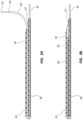
- FIGS. 6 A- 6 Cillustrate an arterio-venous (AV) graft 80 .
- the AV graft 80may be configured as a self-expanding, covered stent graft as shown in FIGS. 6 A- 6 C .
- the access device 10describe previously may be used to percutaneously implant the AV graft 80 using a method described below.
- the AV graft 80may comprise a body 81 and a plurality of anchors 91 .
- the body 81may be cylindrical in shape and may comprise a frame 87 , an internal cover 89 , an external cover 88 , and a bore 83 .
- the frame 87may be composed of any suitable memory material, such as nickel titanium alloy (nitinol).
- the frame 87may be formed by any suitable technique, such as laser cutting, etching, welding, etc.
- the structure of the frame 87may be any suitable structure that allows for radial compression of the frame 87 , expansion of the frame 87 upon release of the radial compression, and resistance to radial compression by surrounding tissue.
- the covers 88 , 89may be formed of any suitable material such that a lumenal surface is hemocompatable and resistant to thrombus formation. An outer surface may promote tissue ingrowth such that the AV graft 80 is anchored within surrounding subcutaneous tissue when implanted.
- suitable materials for the covers 88 , 89are expanded polytetrafluoroethylene (ePTFE), serially deposited PTFE fibers, polyurethane, etc.
- the covers 88 , 89may be composed of the same material.
- the covers 88 , 89may be composed of different materials to facilitate selected functionality with blood or tissue.
- the covers 88 , 89may be composed of a combination of materials.
- the AV graftmay comprise only one cover.
- the plurality of the anchors 91are also shown in FIG. 6 B .
- the anchors 91may be disposed at either a distal end or proximal end of the body 81 . In some embodiments, the anchors 91 are disposed at both the distal and the proximal ends of the body 81 .
- the anchors 91may comprise at least one strut 84 , an apex 85 , and a hook 86 .
- the anchors 91may be coupled to a ring (not shown) that is coupled to an end of the frame 87 and covered by the internal cover 89 and/or the external cover 88 .
- the covers 88 , 89may be coupled to the ring using any suitable technique, such as stitching, gluing, welding, etc.
- the anchors 91may be integral to the frame 87 such that the anchors 91 may be formed as the frame 87 is formed.
- the struts 84may extend radially outward from the end of the body 81 . As shown in FIG. 6 B , the anchors 91 have two struts 84 configured with a 90 degree angle between the struts 84 . In other embodiments, the number of the struts 84 may be 1, 3, 4, or any other suitable number.
- the struts 84may merge at the apex 85 .
- the hook 86may extend along a longitudinal axis of the body 81 toward an opposite end.
- FIG. 6 Cdepicts a cross-sectional view of a portion of the covered stent graft 80 in an expanded configuration.
- the AV graft 80is shown to be coupled to a vessel 90 forming an anastomosis with the vessel 90 .
- the body 81 of the AV graft 80is shown to be expanded and extending through an opening in a wall of the vessel 90 such that a seal around the body 81 by the vessel wall is formed to restrict leakage of blood from the vessel.
- An end of the body 81is shown to be within the opening such that the bore 83 of the body 81 is in fluid communication with a lumen of the vessel.
- the hooks 86 of the anchors 91are shown to be embedded into the vessel wall such that the AV graft 80 is secured to the vessel and axial movement of the AV graft 80 is restricted or prevented.
- FIGS. 7 - 13 BOne exemplary procedure, illustrated in FIGS. 7 - 13 B , is a procedure to percutaneously implant an AV graft to create a vascular access for hemodialysis.
- the AV graftmay be implanted in any suitable location in the patient's body, such as an upper arm, a lower arm, an upper leg, etc. Specific examples include an upper arm loop connecting the brachial artery to an auxiliary vein, a thigh loop graft connecting the femoral artery to the femoral vein, a forearm loop graft, and other locations.
- Various locations wherein a stent graft may be used percutaneously to connect an artery and a veinare within the scope of this disclosure.
- the access sites for the access devices used in the procedureare a femoral vein and a femoral artery.
- Other access sites, such as contralateral brachial artery and basilic vein,are contemplated within the scope of this application.
- the exemplary proceduremay be performed by an interventionalist in a intervention suite. General sedation of the patient and use of a local anesthetic may be administered to the patient for anesthesia.
- FIGS. 7 - 13 Bshow arterial and venous vessels of the patient in cross-section with the elements of the access devices and AV graft implantation elements disposed in various locations during the procedure. The implements are not shown in cross-section for clarity.
- the cross-sectional plane for FIGS. 7 - 13 Bis a plane that includes the longitudinal axis of the vessels.
- a first guidewire 30 ′is inserted into a femoral artery 22 at an arterial access site 17 using an insertion technique such as a Seldinger technique or a modified Seldinger technique with a micropuncture needle and dilator.
- the accessmay be performed under an imaging technique such as fluoroscopy or ultrasound.
- the guidewire 30 ′is advanced through the arterial vasculature, such as a descending aorta 24 , an aortic arch 26 , a subclavian artery 28 , and a brachial artery 14 .
- a distal endis A distal portion of the guidewire 30 ′ is positioned within a distal portion of the right brachial artery 14 of a right upper arm 11 . Advancement of the guidewire 30 ′ may be facilitated by use of fluoroscopy or other suitable imaging technique.
- a second guidewire 30is inserted into a femoral vein 16 at a venous access site 19 .
- the guidewire 30 ′is advanced through the venous vasculature, such as an inferior vena cava 18 , a superior vena cava 21 , a subclavian vein 23 , and an axillary vein 12 .
- a distal portion of the guidewire 30 ′is positioned in the axillary vein 12 of the right upper arm 11 .
- FIGS. 8 A and 8 Billustrate insertion and positioning of the access device 10 ′.
- a first access catheter 42 ′ of the access device 10 ′is threaded over a proximal end of the guidewire 30 ′ and advanced over the guidewire 30 ′ through the arterial vasculature until a distal end of the access catheter 42 ′ is positioned in the brachial artery 14 .
- the access catheter 42 ′may be advanced over the guidewire 30 ′ and properly positioned using fluoroscopy or any other suitable imaging technique.
- the distal end of the access catheter 42 ′is oriented such that a first guide tube 60 ′ is directed toward a wall of the brachial artery 14 .
- Manipulation of the guide tube 60 ′ orientationmay be facilitated by rotation of a handle 44 ′ of the access device 10 ′ such that a slider 51 ′ aligns with the desired orientation of the guide tube 60 ′.
- the guide tube 60 ′is extended from the distal end of the access catheter 42 ′ by displacing the slider 51 ′ proximally.
- the guidewire 30 ′is removed from the access catheter 42 ′.
- a second access catheter 42is positioned in the axillary vein 12 using a similar technique as described above.
- the second access catheter 42is threaded over a proximal end of a guidewire 30 and advanced over the guidewire 30 through the venous vasculature until a distal end of the second access catheter 42 is positioned within the axillary vein 12 .
- a second guide tube 60is oriented, as described above, such that the second guide tube 60 is directed toward a wall of the axillary vein 12 .
- the second guide tube 60is extended from the distal end of the second access catheter 42 by proximal displacement of a slider 51 of handle 44 .
- the guidewire 30is removed from the second access catheter 42 .
- FIGS. 9 A and 9 Bdepict deployment of the stylets 58 , 58 ′ from the guide tubes 60 , 60 ′.
- Stylets 58 , 58 ′are deployed by depression of buttons 53 , 53 ′ of the access devices 10 , 10 ′ respectively.
- the distal end of the stylet 58 ′extends from guide tube 60 ′ and penetrates a wall of the brachial artery 14 forming an arterial exit site 34 .
- the stylet 58 ′may penetrate and pass through subcutaneous tissue and skin adjacent the brachial artery 14 such that the distal end of the stylet 58 ′ is disposed outside of the right upper arm 11 .
- the distal end of the stylet 58penetrates extends from guide tube 60 and passes through a wall of the axillary vein 12 forming a venous exit site 32 . Additionally, the stylet 58 may penetrate and pass through subcutaneous tissue and skin adjacent the axillary vein 12 such that the distal end of the stylet 58 is disposed outside the right upper arm 11 .
- the stylet 58 ′is depicted with the access catheter 42 ′ removed.
- the proximal end of the stylet 58 ′is disposed outside an upper leg 13 of the patient.
- the stylet 58 ′passes through skin and subcutaneous tissue adjacent the femoral artery 22 and into the femoral artery 22 through the arterial access site 17 .
- the stylet 58 ′passes through the arterial vasculature and exits the brachial artery 14 at the arterial exit site 34 .
- the stylet 58 ′may pass through subcutaneous tissue and skin adjacent the brachial artery 14 such that the distal end of the stylet 58 ′ is disposed outside right upper arm 11 .
- the stylet 58is illustrated with the access catheter 42 removed.
- the proximal end of the stylet 58is disposed outside the upper leg 13 of the patient.
- the stylet 58passes through skin and subcutaneous tissue adjacent the femoral vein 16 and into the femoral vein 16 through the venous access site 19 .
- the stylet 58passes through the venous vasculature and exits the axillary vein 12 at the venous exit site 32 and passes through subcutaneous tissue and skin adjacent to the axillary vein 12 such that the distal end of stylet 58 is disposed outside right upper arm 11 .
- FIGS. 11 A and 11 Bdepict the stylets 58 , 58 ′ as illustrated in FIGS. 10 A and 10 B .
- FIGS. 11 A and 11 Bshow a subcutaneous tunnel 38 formed in the right upper arm 11 .
- the tunnel 38extends from the venous exit site 32 in the axillary vein 12 to the arterial exit site 34 in the brachial artery 14 .
- the tunnel 38is configured such that a middle portion of the tunnel 38 is more superficial than end portions of the tunnel 38 to facilitate access of the AV graft during hemodialysis treatments as will be described below.
- the tunnel 38can be formed by making a small incision adjacent the venous exit site 32 .
- a straight or curved subcutaneous tunneling device(not shown) is inserted through the incision into the subcutaneous tissue and directed toward the arterial exit site 34 .
- the tunneling deviceis forced through the subcutaneous tissue until a tunnel 38 is formed from the venous exit site 32 to the arterial exit site 34 .
- the tunneling deviceis removed from the subcutaneous tissue.
- the incisionis made at the arterial exit site 34 and the tunneling device is directed toward the venous exit site 32 .
- FIGS. 12 A and 12 Bshow a configuration of the stylet 58 ′ following passage of a guide catheter (not shown) over the stylet 58 and through the tunnel 38 such that a distal end of the guide catheter is disposed adjacent the arterial exit site 34 .
- the stylet 58 ′is partially retracted such that the distal end of the stylet 58 ′ can be directed into a lumen of the guide catheter.
- the stylet 58is retracted and removed from the guide catheter.
- the stylet 58 ′is advanced through the guide catheter until the distal end of the stylet 58 ′ exits a proximal end of the guide catheter.
- the guide catheteris removed from the stylet 58 ′. As shown in FIGS.
- the stylet 58 ′is depicted to enter the femoral artery 22 at the arterial access site 17 , pass through the arterial vasculature to the brachial artery 14 , and exit the brachial artery 14 at the arterial exit site 34 .
- the stylet 58 ′continues to pass through the tunnel 38 , enter the axillary vein 12 at the venous exit site 32 , pass through the venous vasculature into the femoral vein 16 , and exit the femoral vein 16 at the venous access site 19 .
- the stylet 58 ′is configured to form a loop comprising an arterial leg 36 through the arterial vasculature, a tunnel leg 37 through the tunnel 38 , and a venous leg 39 through the venous vasculature.
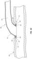
- FIGS. 13 A and 13 Bdepict implantation of the AV graft 80 .
- the stylet 58 ′is shown as depicted in FIGS. 12 A and 12 B .
- a graft delivery catheter 41configured with the AV graft 80 at a distal end portion, is threaded over an end of the stylet 58 ′ extending from the femoral vein 16 and over the venous leg 39 and tunnel leg 37 of the stylet 58 ′.
- a distal end of the delivery catheter 41 and a distal end of the AV graft 80are advanced through the arterial exit site 34 into the brachial artery 14 .
- a proximal end of the AV graft 80is disposed through the venous exit site 32 and within the axillary vein 12 .
- the AV graft 80is released from the delivery catheter 41 and radially expanded within the tunnel 38 .
- the distal end of the AV graft 80is displaced proximally such that the hooks 86 of the anchors 91 penetrate the wall of the brachial artery 14 to form an arterial sutureless anastomosis 43 .
- the proximal end of the AV graft 80is displaced distally such that the hooks 86 of the anchors 91 penetrate the wall of the axillary vein 12 to form a venous sutureless anastomosis 49 .
- the stylet 58 ′ and the delivery catheter 41are retracted and removed from the patient.
- the bore 83 of the AV graft 80is fluidly coupled to the brachial artery 14 and the axillary vein 12 such that blood flows from the brachial artery 14 through the AV graft 80 and into the axillary vein 12 .
- Implantation of other types of grafts, such as balloon expandable grafts, non-stent grafts, tissue engineered grafts, bovine grafts, allografts, etc.,is contemplated within the scope of this application.
- the AV graft 80can be used to treat the renal failure patient with hemodialysis.
- the AV graft 80can be palpated through the skin of the patient by a healthcare worker and accessed with hemodialysis needles.
- the needlescan be fluidly coupled to a hemodialysis set including a filter.
- the setcan be coupled to a dialysis machine. Blood can be withdrawn from the AV graft 80 through an arterial dialysis needle, passed through the filter to remove toxins, and returned to the AV graft 80 and the patient.
- Hemodialysis treatmentsmay be delivered three to five times a week.
Landscapes
- Health & Medical Sciences (AREA)
- Life Sciences & Earth Sciences (AREA)
- Heart & Thoracic Surgery (AREA)
- Engineering & Computer Science (AREA)
- Biomedical Technology (AREA)
- Veterinary Medicine (AREA)
- General Health & Medical Sciences (AREA)
- Public Health (AREA)
- Animal Behavior & Ethology (AREA)
- Vascular Medicine (AREA)
- Pulmonology (AREA)
- Surgery (AREA)
- Cardiology (AREA)
- Anesthesiology (AREA)
- Hematology (AREA)
- Oral & Maxillofacial Surgery (AREA)
- Transplantation (AREA)
- Gastroenterology & Hepatology (AREA)
- Biophysics (AREA)
- Molecular Biology (AREA)
- Medical Informatics (AREA)
- Nuclear Medicine, Radiotherapy & Molecular Imaging (AREA)
- Pathology (AREA)
- Prostheses (AREA)
Abstract
Description
Claims (10)
Priority Applications (2)
| Application Number | Priority Date | Filing Date | Title |
|---|---|---|---|
| US15/855,672US11654224B2 (en) | 2016-12-30 | 2017-12-27 | Methods and devices for percutaneous implantation of arterio-venous grafts |
| US18/301,931US20230381395A1 (en) | 2016-12-30 | 2023-04-17 | Methods and devices for percutaneous implantation of arterio-venous grafts |
Applications Claiming Priority (2)
| Application Number | Priority Date | Filing Date | Title |
|---|---|---|---|
| US201662440765P | 2016-12-30 | 2016-12-30 | |
| US15/855,672US11654224B2 (en) | 2016-12-30 | 2017-12-27 | Methods and devices for percutaneous implantation of arterio-venous grafts |
Related Child Applications (1)
| Application Number | Title | Priority Date | Filing Date |
|---|---|---|---|
| US18/301,931DivisionUS20230381395A1 (en) | 2016-12-30 | 2023-04-17 | Methods and devices for percutaneous implantation of arterio-venous grafts |
Publications (2)
| Publication Number | Publication Date |
|---|---|
| US20180185563A1 US20180185563A1 (en) | 2018-07-05 |
| US11654224B2true US11654224B2 (en) | 2023-05-23 |
Family
ID=62706509
Family Applications (2)
| Application Number | Title | Priority Date | Filing Date |
|---|---|---|---|
| US15/855,672Active2039-12-19US11654224B2 (en) | 2016-12-30 | 2017-12-27 | Methods and devices for percutaneous implantation of arterio-venous grafts |
| US18/301,931PendingUS20230381395A1 (en) | 2016-12-30 | 2023-04-17 | Methods and devices for percutaneous implantation of arterio-venous grafts |
Family Applications After (1)
| Application Number | Title | Priority Date | Filing Date |
|---|---|---|---|
| US18/301,931PendingUS20230381395A1 (en) | 2016-12-30 | 2023-04-17 | Methods and devices for percutaneous implantation of arterio-venous grafts |
Country Status (3)
| Country | Link |
|---|---|
| US (2) | US11654224B2 (en) |
| AU (1) | AU2018200025A1 (en) |
| CA (1) | CA2990537A1 (en) |
Cited By (1)
| Publication number | Priority date | Publication date | Assignee | Title |
|---|---|---|---|---|
| US11938260B2 (en) | 2017-03-31 | 2024-03-26 | InnAVasc Medical, Inc. | Apparatus and method for cannulation of vascular access graft |
Families Citing this family (8)
| Publication number | Priority date | Publication date | Assignee | Title |
|---|---|---|---|---|
| GB0419954D0 (en) | 2004-09-08 | 2004-10-13 | Advotek Medical Devices Ltd | System for directing therapy |
| US20130190676A1 (en) | 2006-04-20 | 2013-07-25 | Limflow Gmbh | Devices and methods for fluid flow through body passages |
| CA2898879C (en) | 2013-03-08 | 2023-05-02 | Limflow Gmbh | Methods and systems for providing or maintaining fluid flow through body passages |
| EP3609415B1 (en) | 2017-04-10 | 2023-08-23 | LimFlow GmbH | Devices for treating lower extremity vasculature |
| SG11202102500UA (en) | 2018-10-09 | 2021-04-29 | Limflow Gmbh | Devices and methods for catheter alignment |
| US11793623B1 (en)* | 2019-10-14 | 2023-10-24 | Avenu Medical, Inc | Systems and methods for percutaneously placing biologic grafts at a procedural site |
| EP4051174A4 (en) | 2019-11-01 | 2023-11-22 | LimFlow GmbH | Devices and methods for increasing blood perfusion to a distal extremity |
| CN117122354B (en)* | 2023-06-21 | 2024-03-15 | 苏州科技城医院 | Subcutaneous tunnel device assembly for artificial blood vessel arteriovenous internal fistula |
Citations (94)
| Publication number | Priority date | Publication date | Assignee | Title |
|---|---|---|---|---|
| US4559039A (en) | 1983-12-05 | 1985-12-17 | Purdue Research Foundation | Permanently placed transcutaneous access device to blood vessels |
| US4790825A (en) | 1986-09-05 | 1988-12-13 | Electro Catheter Corporation | Closed chest cannulation method and device for atrial-major artery bypass |
| US4966163A (en) | 1989-02-14 | 1990-10-30 | Advanced Cardiovascular Systems, Inc. | Extendable guidewire for vascular procedures |
| US5295493A (en) | 1992-03-19 | 1994-03-22 | Interventional Technologies, Inc. | Anatomical guide wire |
| US5389090A (en) | 1994-02-07 | 1995-02-14 | Cathco, Inc. | Guiding catheter with straightening dilator |
| US5421348A (en) | 1993-11-29 | 1995-06-06 | Cordis Corporation | Rotating guidewire extension system with mechanically locking extension wire |
| US5492530A (en) | 1994-02-07 | 1996-02-20 | Cathco, Inc. | Method for accessing the coronary arteries from the radial or brachial artery in the arm |
| US5685820A (en) | 1990-11-06 | 1997-11-11 | Partomed Medizintechnik Gmbh | Instrument for the penetration of body tissue |
| US5733248A (en) | 1995-11-29 | 1998-03-31 | Scimed Life Systems, Inc. | Universal guide catheter |
| US6047700A (en) | 1998-03-30 | 2000-04-11 | Arthrocare Corporation | Systems and methods for electrosurgical removal of calcified deposits |
| US6068638A (en) | 1995-10-13 | 2000-05-30 | Transvascular, Inc. | Device, system and method for interstitial transvascular intervention |
| US6102926A (en) | 1996-12-02 | 2000-08-15 | Angiotrax, Inc. | Apparatus for percutaneously performing myocardial revascularization having means for sensing tissue parameters and methods of use |
| US6190353B1 (en) | 1995-10-13 | 2001-02-20 | Transvascular, Inc. | Methods and apparatus for bypassing arterial obstructions and/or performing other transvascular procedures |
| US6217527B1 (en) | 1998-09-30 | 2001-04-17 | Lumend, Inc. | Methods and apparatus for crossing vascular occlusions |
| US20010010006A1 (en)* | 1997-04-23 | 2001-07-26 | St. Jude Medical Cardiovascular Goup Inc. | Medical grafting connectors and fasteners |
| US20010012924A1 (en) | 1998-01-13 | 2001-08-09 | Milo Charles F. | Methods and apparatus for crossing total occlusions in blood vessels |
| US20010023346A1 (en) | 1999-05-04 | 2001-09-20 | Cardiodyne, Inc. | Method and devices for creating a trap for confining therapeutic drugs and/or genes in the myocardium |
| US20010034547A1 (en) | 1998-09-10 | 2001-10-25 | Percardia, Inc. | Delivery methods for left ventricular conduit |
| US20020004666A1 (en) | 2000-05-22 | 2002-01-10 | Michael Schwager | Catheter arrangement |
| US20020029060A1 (en) | 1998-07-29 | 2002-03-07 | Michael Hogendijk | Surgical cutting instrument and method of use |
| US20020120250A1 (en) | 1998-08-11 | 2002-08-29 | Altman Peter A. | Catheter drug delivery system and method for use |
| US20020122877A1 (en) | 2000-12-28 | 2002-09-05 | Sameer Harish | Methods of forming a coating for a prosthesis |
| US20020133168A1 (en) | 2001-03-16 | 2002-09-19 | Smedley Gregory T. | Applicator and methods for placing a trabecular shunt for glaucoma treatment |
| US6475226B1 (en) | 1999-02-03 | 2002-11-05 | Scimed Life Systems, Inc. | Percutaneous bypass apparatus and method |
| US20020169377A1 (en) | 2000-04-13 | 2002-11-14 | Khairkhahan Alexander K. | Method and apparatus for accessing the left atrial appendage |
| US6485513B1 (en)* | 1999-10-08 | 2002-11-26 | The General Hospital Corporation | Percutaneous stent graft and method for vascular bypass |
| US6508777B1 (en) | 1998-05-08 | 2003-01-21 | Cardeon Corporation | Circulatory support system and method of use for isolated segmental perfusion |
| US20030040771A1 (en) | 1999-02-01 | 2003-02-27 | Hideki Hyodoh | Methods for creating woven devices |
| US6554792B2 (en) | 1999-05-21 | 2003-04-29 | Mallinckrodt Inc. | Suspension device and method |
| US6554794B1 (en) | 1997-09-24 | 2003-04-29 | Richard L. Mueller | Non-deforming deflectable multi-lumen catheter |
| US6623480B1 (en) | 1998-07-24 | 2003-09-23 | University Of Kentucky Research Foundation | Flexible recording/high energy electrode catheter with anchor for ablation of atrial flutter by radio frequency energy |
| US20040039371A1 (en) | 2002-08-23 | 2004-02-26 | Bruce Tockman | Coronary vein navigator |
| US6709444B1 (en) | 1996-02-02 | 2004-03-23 | Transvascular, Inc. | Methods for bypassing total or near-total obstructions in arteries or other anatomical conduits |
| US6726677B1 (en) | 1995-10-13 | 2004-04-27 | Transvascular, Inc. | Stabilized tissue penetrating catheters |
| US20040082850A1 (en) | 2002-10-23 | 2004-04-29 | Medtonic, Inc. | Methods and apparatus for locating body vessels and occlusions in body vessels |
| US20040097880A1 (en) | 2002-11-19 | 2004-05-20 | Angiodynamics, Inc. | Combination thrombolytic infusion catheter and dilator system |
| US20040116878A1 (en) | 2002-12-16 | 2004-06-17 | Byrd Charles L. | Bilumen guide catheters for accessing cardiac sites |
| US20040133168A1 (en) | 2002-12-23 | 2004-07-08 | Salcudean Septimiu E. | Steerable needle |
| US20040181238A1 (en) | 2003-03-14 | 2004-09-16 | David Zarbatany | Mitral valve repair system and method for use |
| US20040181150A1 (en) | 1999-09-01 | 2004-09-16 | Bacchus Vascular, Inc. | Methods and apparatus for accessing and treating body lumens |
| US20050101984A1 (en) | 2003-11-06 | 2005-05-12 | Nmt Medical, Inc. | Transseptal puncture apparatus |
| WO2005053547A2 (en) | 2003-11-28 | 2005-06-16 | Cook Incorporated | Vascular occlusion methods, systems and devices |
| US20050149094A1 (en) | 2003-10-31 | 2005-07-07 | Olympus Corporation | Trocar |
| US20050149097A1 (en) | 2003-12-30 | 2005-07-07 | Regnell Sandra J. | Transseptal needle |
| US20050209579A1 (en) | 2004-03-22 | 2005-09-22 | Yacoubian Vahe S | System, methods and apparatus for cerebral protection |
| US6955657B1 (en) | 2001-12-31 | 2005-10-18 | Advanced Cardiovascular Systems, Inc. | Intra-ventricular substance delivery catheter system |
| US20050279370A1 (en) | 1997-07-11 | 2005-12-22 | A-Med Systems, Inc. | Methods and systems for providing right and/or left heart support during cardiac surgery |
| US20060009737A1 (en) | 2004-07-12 | 2006-01-12 | Whiting James S | Methods and devices for transseptal access |
| US7008979B2 (en) | 2002-04-30 | 2006-03-07 | Hydromer, Inc. | Coating composition for multiple hydrophilic applications |
| US20060135962A1 (en) | 2004-09-09 | 2006-06-22 | Kick George F | Expandable trans-septal sheath |
| US20060173440A1 (en) | 2001-01-17 | 2006-08-03 | Medtronic Vascular, Inc. | Microcatheter Devices and Methods for Targeted Substance Delivery |
| US20060247750A1 (en) | 2005-04-28 | 2006-11-02 | Seifert Kevin R | Guide catheters for accessing cardiac sites |
| US20070021767A1 (en) | 2005-07-25 | 2007-01-25 | Breznock Eugene M | Steerable endoluminal punch |
| US20070203515A1 (en) | 2006-01-25 | 2007-08-30 | Heuser Richard R | Catheter system for connecting adjacent blood vessels |
| US7344567B2 (en) | 2004-07-21 | 2008-03-18 | Prosthetic Design, Inc. | Immediate postoperative prosthesis |
| US20080082136A1 (en) | 2006-10-03 | 2008-04-03 | Gaudiani Vincent A | Transcoronary Sinus Pacing System, LV Summit Pacing, Early Mitral Closure Pacing, and Methods Therefor |
| US7374567B2 (en) | 2006-01-25 | 2008-05-20 | Heuser Richard R | Catheter system for connecting adjacent blood vessels |
| US20080125748A1 (en) | 2006-09-25 | 2008-05-29 | Medtronic Vascular, Inc. | High Torque, Low Profile Catheters and Methods for Transluminal Interventions |
| US20080154172A1 (en) | 2006-12-20 | 2008-06-26 | Medtronic Vascular, Inc. | Low Profile Catheters and Methods for Treatment of Chronic Total Occlusions and Other Disorders |
| US20080171944A1 (en) | 2005-07-26 | 2008-07-17 | Rox Medical, Inc. | Devices, systems, and methods for peripheral arteriovenous fistula creation |
| US20080215008A1 (en) | 2006-12-20 | 2008-09-04 | Nance Edward J | Expandable trans-septal sheath |
| US20080228171A1 (en) | 2006-11-21 | 2008-09-18 | Kugler Chad J | Endovascular devices and methods for exploiting intramural space |
| US20080249565A1 (en) | 1996-08-22 | 2008-10-09 | The Trustees Of Columbia University In The City Of New York | Endovascular Flexible Stapling Device |
| US20090024072A1 (en) | 2007-07-18 | 2009-01-22 | Enrique Criado | Methods and systems for establishing retrograde carotid arterial blood flow |
| US20090112050A1 (en) | 2007-10-24 | 2009-04-30 | Circulite, Inc. | Transseptal cannula, tip, delivery system, and method |
| US20090240122A1 (en) | 2006-05-04 | 2009-09-24 | The Cleveland Clinic Foundation | Intrajugular catheter |
| US7648517B2 (en) | 1995-10-13 | 2010-01-19 | Medtronic Vascular, Inc. | Catheters and related devices for forming passageways between blood vessels or other anatomical structures |
| US20100185216A1 (en) | 2008-08-13 | 2010-07-22 | Garrison Michi E | Suture delivery device |
| US20100249491A1 (en) | 2009-03-27 | 2010-09-30 | Circulite, Inc. | Two-piece transseptal cannula, delivery system, and method of delivery |
| WO2011068540A1 (en) | 2009-12-03 | 2011-06-09 | Therix Medical Development, Ltd. | Central venous access system |
| US20110178530A1 (en) | 2007-01-30 | 2011-07-21 | Bly Mark J | Direct delivery system for transvascular lead |
| US8019420B2 (en) | 2003-08-21 | 2011-09-13 | Medtronic, Inc. | Medical lead connector systems with adapters |
| US20120130468A1 (en) | 2010-07-27 | 2012-05-24 | Fred Khosravi | Methods and apparatus for treating neurovascular venous outflow obstruction |
| US20120136247A1 (en) | 2006-05-02 | 2012-05-31 | Lakshmikumar Pillai | Methods of Transvascular Retrograde Access Placement and Devices for Facilitating the Placement |
| US20120136366A1 (en) | 2006-05-02 | 2012-05-31 | Lakshmikumar Pillai | Methods of Transvascular Retrograde Access Placement and Devices For Facilitating Therein |
| US8241311B2 (en) | 2009-12-15 | 2012-08-14 | Medtronic Vascular, Inc. | Methods and systems for bypassing an occlusion in a blood vessel |
| US20120290075A1 (en) | 2011-05-10 | 2012-11-15 | Abbott Cardiovascular Systems Inc. | Modification of bioabsorbable stent to reduce thrombogenecity |
| US20130006282A1 (en) | 2011-06-29 | 2013-01-03 | Matthew Wilkinson | System and method for re-entering a vessel lumen |
| US8374680B2 (en) | 2008-04-21 | 2013-02-12 | Medtronic Vascular, Inc. | Needleless catheters and methods for true lumen re-entry in treatment of chronic total occlusions and other disorders |
| US20130072957A1 (en) | 2011-09-19 | 2013-03-21 | Boston Scientific Scimed, Inc. | Subintimal re-entry catheter and retrograde recanalization |
| US8409236B2 (en) | 2009-08-21 | 2013-04-02 | Vascular Access Technologies, Inc. | Methods of transvascular retrograde access placement and devices for facilitating the placement |
| WO2013119547A1 (en) | 2012-02-09 | 2013-08-15 | Therix Medical Development, Ltd. | Occlusion access system |
| US20130324901A1 (en)* | 2012-05-30 | 2013-12-05 | Lakshmikumar Pillai | Transvascular Access Methods |
| US20130324967A1 (en)* | 2012-05-30 | 2013-12-05 | Lakshmikumar Pillai | Transvascular access device and method |
| US20140018837A1 (en) | 2012-07-13 | 2014-01-16 | Boston Scientifc Scimed, Inc. | Subintimal reentry system |
| US20140046346A1 (en) | 2012-08-09 | 2014-02-13 | Silk Road Medical, Inc. | Suture Delivery Device |
| US20140142418A1 (en) | 2012-02-09 | 2014-05-22 | Therix Medical Development, Ltd. | Occlusion access system |
| US20140142677A1 (en) | 2012-04-23 | 2014-05-22 | Pq Bypass, Inc. | Methods and systems for bypassing occlusions in a femoral artery |
| US20140288634A1 (en)* | 2011-09-01 | 2014-09-25 | Endospan Ltd. | Double-layer stent |
| US20150320357A1 (en) | 2014-02-20 | 2015-11-12 | GraftWorx, LLC | Methods for assessing fluid flow through a conduit |
| US9282967B2 (en)* | 2007-08-02 | 2016-03-15 | Bioconnect Systems, Inc. | Implantable flow connector |
| US20170035591A1 (en)* | 2014-04-10 | 2017-02-09 | Carag Ag | A Kit for Placing a Bypass |
| US20170296798A1 (en) | 2014-09-04 | 2017-10-19 | Silk Road Medical, Inc. | Methods and Devices for Transcarotid Access |
| US20180161551A1 (en) | 2016-12-09 | 2018-06-14 | Vascular Access Technologies, Inc. | Trans-jugular carotid artery access methods |
Family Cites Families (2)
| Publication number | Priority date | Publication date | Assignee | Title |
|---|---|---|---|---|
| US9486276B2 (en)* | 2012-10-11 | 2016-11-08 | Tva Medical, Inc. | Devices and methods for fistula formation |
| US9463104B2 (en)* | 2013-06-07 | 2016-10-11 | Cedars-Sinai Medical Center | Vascular graft device placement methods |
- 2017
- 2017-12-27USUS15/855,672patent/US11654224B2/enactiveActive
- 2017-12-29CACA2990537Apatent/CA2990537A1/enactivePending
- 2018
- 2018-01-02AUAU2018200025Apatent/AU2018200025A1/ennot_activeAbandoned
- 2023
- 2023-04-17USUS18/301,931patent/US20230381395A1/enactivePending
Patent Citations (106)
| Publication number | Priority date | Publication date | Assignee | Title |
|---|---|---|---|---|
| US4559039A (en) | 1983-12-05 | 1985-12-17 | Purdue Research Foundation | Permanently placed transcutaneous access device to blood vessels |
| US4790825A (en) | 1986-09-05 | 1988-12-13 | Electro Catheter Corporation | Closed chest cannulation method and device for atrial-major artery bypass |
| US4966163A (en) | 1989-02-14 | 1990-10-30 | Advanced Cardiovascular Systems, Inc. | Extendable guidewire for vascular procedures |
| US5685820A (en) | 1990-11-06 | 1997-11-11 | Partomed Medizintechnik Gmbh | Instrument for the penetration of body tissue |
| US5295493A (en) | 1992-03-19 | 1994-03-22 | Interventional Technologies, Inc. | Anatomical guide wire |
| US5421348A (en) | 1993-11-29 | 1995-06-06 | Cordis Corporation | Rotating guidewire extension system with mechanically locking extension wire |
| US5389090A (en) | 1994-02-07 | 1995-02-14 | Cathco, Inc. | Guiding catheter with straightening dilator |
| US5492530A (en) | 1994-02-07 | 1996-02-20 | Cathco, Inc. | Method for accessing the coronary arteries from the radial or brachial artery in the arm |
| US20040059280A1 (en) | 1995-10-13 | 2004-03-25 | Trans Vascular, Inc. | Methods and apparatus for bypassing arterial obstructions and/or performing other transvascular procedures |
| US6068638A (en) | 1995-10-13 | 2000-05-30 | Transvascular, Inc. | Device, system and method for interstitial transvascular intervention |
| US6726677B1 (en) | 1995-10-13 | 2004-04-27 | Transvascular, Inc. | Stabilized tissue penetrating catheters |
| US6190353B1 (en) | 1995-10-13 | 2001-02-20 | Transvascular, Inc. | Methods and apparatus for bypassing arterial obstructions and/or performing other transvascular procedures |
| US7648517B2 (en) | 1995-10-13 | 2010-01-19 | Medtronic Vascular, Inc. | Catheters and related devices for forming passageways between blood vessels or other anatomical structures |
| US5733248A (en) | 1995-11-29 | 1998-03-31 | Scimed Life Systems, Inc. | Universal guide catheter |
| US6709444B1 (en) | 1996-02-02 | 2004-03-23 | Transvascular, Inc. | Methods for bypassing total or near-total obstructions in arteries or other anatomical conduits |
| US20080249565A1 (en) | 1996-08-22 | 2008-10-09 | The Trustees Of Columbia University In The City Of New York | Endovascular Flexible Stapling Device |
| US6102926A (en) | 1996-12-02 | 2000-08-15 | Angiotrax, Inc. | Apparatus for percutaneously performing myocardial revascularization having means for sensing tissue parameters and methods of use |
| US20010010006A1 (en)* | 1997-04-23 | 2001-07-26 | St. Jude Medical Cardiovascular Goup Inc. | Medical grafting connectors and fasteners |
| US20050279370A1 (en) | 1997-07-11 | 2005-12-22 | A-Med Systems, Inc. | Methods and systems for providing right and/or left heart support during cardiac surgery |
| US6554794B1 (en) | 1997-09-24 | 2003-04-29 | Richard L. Mueller | Non-deforming deflectable multi-lumen catheter |
| US20010012924A1 (en) | 1998-01-13 | 2001-08-09 | Milo Charles F. | Methods and apparatus for crossing total occlusions in blood vessels |
| US6047700A (en) | 1998-03-30 | 2000-04-11 | Arthrocare Corporation | Systems and methods for electrosurgical removal of calcified deposits |
| US6508777B1 (en) | 1998-05-08 | 2003-01-21 | Cardeon Corporation | Circulatory support system and method of use for isolated segmental perfusion |
| US6623480B1 (en) | 1998-07-24 | 2003-09-23 | University Of Kentucky Research Foundation | Flexible recording/high energy electrode catheter with anchor for ablation of atrial flutter by radio frequency energy |
| US20020029060A1 (en) | 1998-07-29 | 2002-03-07 | Michael Hogendijk | Surgical cutting instrument and method of use |
| US20020120250A1 (en) | 1998-08-11 | 2002-08-29 | Altman Peter A. | Catheter drug delivery system and method for use |
| US20010034547A1 (en) | 1998-09-10 | 2001-10-25 | Percardia, Inc. | Delivery methods for left ventricular conduit |
| US6217527B1 (en) | 1998-09-30 | 2001-04-17 | Lumend, Inc. | Methods and apparatus for crossing vascular occlusions |
| US20030040771A1 (en) | 1999-02-01 | 2003-02-27 | Hideki Hyodoh | Methods for creating woven devices |
| US6475226B1 (en) | 1999-02-03 | 2002-11-05 | Scimed Life Systems, Inc. | Percutaneous bypass apparatus and method |
| US20010023346A1 (en) | 1999-05-04 | 2001-09-20 | Cardiodyne, Inc. | Method and devices for creating a trap for confining therapeutic drugs and/or genes in the myocardium |
| US6554792B2 (en) | 1999-05-21 | 2003-04-29 | Mallinckrodt Inc. | Suspension device and method |
| US20040181150A1 (en) | 1999-09-01 | 2004-09-16 | Bacchus Vascular, Inc. | Methods and apparatus for accessing and treating body lumens |
| US6485513B1 (en)* | 1999-10-08 | 2002-11-26 | The General Hospital Corporation | Percutaneous stent graft and method for vascular bypass |
| US20020169377A1 (en) | 2000-04-13 | 2002-11-14 | Khairkhahan Alexander K. | Method and apparatus for accessing the left atrial appendage |
| US20020004666A1 (en) | 2000-05-22 | 2002-01-10 | Michael Schwager | Catheter arrangement |
| US20020122877A1 (en) | 2000-12-28 | 2002-09-05 | Sameer Harish | Methods of forming a coating for a prosthesis |
| US20060173440A1 (en) | 2001-01-17 | 2006-08-03 | Medtronic Vascular, Inc. | Microcatheter Devices and Methods for Targeted Substance Delivery |
| US20020133168A1 (en) | 2001-03-16 | 2002-09-19 | Smedley Gregory T. | Applicator and methods for placing a trabecular shunt for glaucoma treatment |
| US6955657B1 (en) | 2001-12-31 | 2005-10-18 | Advanced Cardiovascular Systems, Inc. | Intra-ventricular substance delivery catheter system |
| US7008979B2 (en) | 2002-04-30 | 2006-03-07 | Hydromer, Inc. | Coating composition for multiple hydrophilic applications |
| WO2004018029A2 (en) | 2002-08-23 | 2004-03-04 | Cardiac Pacemakers, Inc. | Coronary vein navigator |
| US20040039371A1 (en) | 2002-08-23 | 2004-02-26 | Bruce Tockman | Coronary vein navigator |
| US20040082850A1 (en) | 2002-10-23 | 2004-04-29 | Medtonic, Inc. | Methods and apparatus for locating body vessels and occlusions in body vessels |
| US20040097880A1 (en) | 2002-11-19 | 2004-05-20 | Angiodynamics, Inc. | Combination thrombolytic infusion catheter and dilator system |
| US20040116878A1 (en) | 2002-12-16 | 2004-06-17 | Byrd Charles L. | Bilumen guide catheters for accessing cardiac sites |
| US20040133168A1 (en) | 2002-12-23 | 2004-07-08 | Salcudean Septimiu E. | Steerable needle |
| US20040181238A1 (en) | 2003-03-14 | 2004-09-16 | David Zarbatany | Mitral valve repair system and method for use |
| US8019420B2 (en) | 2003-08-21 | 2011-09-13 | Medtronic, Inc. | Medical lead connector systems with adapters |
| US20050149094A1 (en) | 2003-10-31 | 2005-07-07 | Olympus Corporation | Trocar |
| US20050101984A1 (en) | 2003-11-06 | 2005-05-12 | Nmt Medical, Inc. | Transseptal puncture apparatus |
| WO2005053547A2 (en) | 2003-11-28 | 2005-06-16 | Cook Incorporated | Vascular occlusion methods, systems and devices |
| US20050149097A1 (en) | 2003-12-30 | 2005-07-07 | Regnell Sandra J. | Transseptal needle |
| US20050209579A1 (en) | 2004-03-22 | 2005-09-22 | Yacoubian Vahe S | System, methods and apparatus for cerebral protection |
| US20060009737A1 (en) | 2004-07-12 | 2006-01-12 | Whiting James S | Methods and devices for transseptal access |
| US7344567B2 (en) | 2004-07-21 | 2008-03-18 | Prosthetic Design, Inc. | Immediate postoperative prosthesis |
| US20060135962A1 (en) | 2004-09-09 | 2006-06-22 | Kick George F | Expandable trans-septal sheath |
| US20060247750A1 (en) | 2005-04-28 | 2006-11-02 | Seifert Kevin R | Guide catheters for accessing cardiac sites |
| US20070021767A1 (en) | 2005-07-25 | 2007-01-25 | Breznock Eugene M | Steerable endoluminal punch |
| US20080171944A1 (en) | 2005-07-26 | 2008-07-17 | Rox Medical, Inc. | Devices, systems, and methods for peripheral arteriovenous fistula creation |
| US20070203515A1 (en) | 2006-01-25 | 2007-08-30 | Heuser Richard R | Catheter system for connecting adjacent blood vessels |
| US7374567B2 (en) | 2006-01-25 | 2008-05-20 | Heuser Richard R | Catheter system for connecting adjacent blood vessels |
| US20120136366A1 (en) | 2006-05-02 | 2012-05-31 | Lakshmikumar Pillai | Methods of Transvascular Retrograde Access Placement and Devices For Facilitating Therein |
| US20120136247A1 (en) | 2006-05-02 | 2012-05-31 | Lakshmikumar Pillai | Methods of Transvascular Retrograde Access Placement and Devices for Facilitating the Placement |
| US9511214B2 (en) | 2006-05-02 | 2016-12-06 | Vascular Access Technologies, Inc. | Methods of transvascular retrograde access placement and devices for facilitating therein |
| US20170056625A1 (en) | 2006-05-02 | 2017-03-02 | Lakshmikumar Pillai | Devices for transvascular retrograde access placement |
| US20200069919A1 (en) | 2006-05-02 | 2020-03-05 | Vascular Access Technologies, Inc. | Devices for transvascular retrograde access placement |
| US20090240122A1 (en) | 2006-05-04 | 2009-09-24 | The Cleveland Clinic Foundation | Intrajugular catheter |
| US20080125748A1 (en) | 2006-09-25 | 2008-05-29 | Medtronic Vascular, Inc. | High Torque, Low Profile Catheters and Methods for Transluminal Interventions |
| US20080082136A1 (en) | 2006-10-03 | 2008-04-03 | Gaudiani Vincent A | Transcoronary Sinus Pacing System, LV Summit Pacing, Early Mitral Closure Pacing, and Methods Therefor |
| US20080228171A1 (en) | 2006-11-21 | 2008-09-18 | Kugler Chad J | Endovascular devices and methods for exploiting intramural space |
| US20080215008A1 (en) | 2006-12-20 | 2008-09-04 | Nance Edward J | Expandable trans-septal sheath |
| US20080154172A1 (en) | 2006-12-20 | 2008-06-26 | Medtronic Vascular, Inc. | Low Profile Catheters and Methods for Treatment of Chronic Total Occlusions and Other Disorders |
| US20110178530A1 (en) | 2007-01-30 | 2011-07-21 | Bly Mark J | Direct delivery system for transvascular lead |
| US20090024072A1 (en) | 2007-07-18 | 2009-01-22 | Enrique Criado | Methods and systems for establishing retrograde carotid arterial blood flow |
| US9282967B2 (en)* | 2007-08-02 | 2016-03-15 | Bioconnect Systems, Inc. | Implantable flow connector |
| US20090112050A1 (en) | 2007-10-24 | 2009-04-30 | Circulite, Inc. | Transseptal cannula, tip, delivery system, and method |
| US8374680B2 (en) | 2008-04-21 | 2013-02-12 | Medtronic Vascular, Inc. | Needleless catheters and methods for true lumen re-entry in treatment of chronic total occlusions and other disorders |
| US20100185216A1 (en) | 2008-08-13 | 2010-07-22 | Garrison Michi E | Suture delivery device |
| US20100249491A1 (en) | 2009-03-27 | 2010-09-30 | Circulite, Inc. | Two-piece transseptal cannula, delivery system, and method of delivery |
| US8409236B2 (en) | 2009-08-21 | 2013-04-02 | Vascular Access Technologies, Inc. | Methods of transvascular retrograde access placement and devices for facilitating the placement |
| US8568435B2 (en) | 2009-08-21 | 2013-10-29 | Vascular Access Technologies, Inc. | Transvascular retrograde access devices |
| US20110295206A1 (en) | 2009-12-03 | 2011-12-01 | John Gurley | Central venous access system |
| WO2011068540A1 (en) | 2009-12-03 | 2011-06-09 | Therix Medical Development, Ltd. | Central venous access system |
| US8241311B2 (en) | 2009-12-15 | 2012-08-14 | Medtronic Vascular, Inc. | Methods and systems for bypassing an occlusion in a blood vessel |
| US20120130468A1 (en) | 2010-07-27 | 2012-05-24 | Fred Khosravi | Methods and apparatus for treating neurovascular venous outflow obstruction |
| US20120290075A1 (en) | 2011-05-10 | 2012-11-15 | Abbott Cardiovascular Systems Inc. | Modification of bioabsorbable stent to reduce thrombogenecity |
| US20130006282A1 (en) | 2011-06-29 | 2013-01-03 | Matthew Wilkinson | System and method for re-entering a vessel lumen |
| US20140288634A1 (en)* | 2011-09-01 | 2014-09-25 | Endospan Ltd. | Double-layer stent |
| US20130072957A1 (en) | 2011-09-19 | 2013-03-21 | Boston Scientific Scimed, Inc. | Subintimal re-entry catheter and retrograde recanalization |
| WO2013119547A1 (en) | 2012-02-09 | 2013-08-15 | Therix Medical Development, Ltd. | Occlusion access system |
| US20140142418A1 (en) | 2012-02-09 | 2014-05-22 | Therix Medical Development, Ltd. | Occlusion access system |
| US20140142677A1 (en) | 2012-04-23 | 2014-05-22 | Pq Bypass, Inc. | Methods and systems for bypassing occlusions in a femoral artery |
| US20190321600A1 (en) | 2012-05-30 | 2019-10-24 | Vascular Access Technologies, Inc. | Transvascular access methods |
| US9220874B2 (en) | 2012-05-30 | 2015-12-29 | Vascular Access Technologies, Inc. | Transvascular access device and method |
| US20130324967A1 (en)* | 2012-05-30 | 2013-12-05 | Lakshmikumar Pillai | Transvascular access device and method |
| US9623217B2 (en) | 2012-05-30 | 2017-04-18 | Vascular Access Techonlogies, Inc. | Transvascular access methods |
| US20130324901A1 (en)* | 2012-05-30 | 2013-12-05 | Lakshmikumar Pillai | Transvascular Access Methods |
| US20220401704A1 (en) | 2012-05-30 | 2022-12-22 | Vascular Access Technologies, Inc. | Transvascular access methods |
| US20140018837A1 (en) | 2012-07-13 | 2014-01-16 | Boston Scientifc Scimed, Inc. | Subintimal reentry system |
| US20140046346A1 (en) | 2012-08-09 | 2014-02-13 | Silk Road Medical, Inc. | Suture Delivery Device |
| US20150320357A1 (en) | 2014-02-20 | 2015-11-12 | GraftWorx, LLC | Methods for assessing fluid flow through a conduit |
| US20170035591A1 (en)* | 2014-04-10 | 2017-02-09 | Carag Ag | A Kit for Placing a Bypass |
| US20170296798A1 (en) | 2014-09-04 | 2017-10-19 | Silk Road Medical, Inc. | Methods and Devices for Transcarotid Access |
| US20180161551A1 (en) | 2016-12-09 | 2018-06-14 | Vascular Access Technologies, Inc. | Trans-jugular carotid artery access methods |
| US20200338320A1 (en) | 2016-12-09 | 2020-10-29 | Vascular Access Technologies, Inc. | Trans-jugular carotid artery access methods |
Non-Patent Citations (32)
| Title |
|---|
| Faul, et al., Vascular Disease Management, vol. 5 No. 5 ,Sep./Oct. 2008 ,128-133. |
| Huang, et al., Evaluation of the Needle Technique for Producing an Arteriovenous Fistula, Journal of Applied Physiology, vol. 77(6) ,Dec. 1994 ,2907-2911. |
| Khanna , et al., "sharpening of Hollow Silicon Microneedles to Reduce Skin Penetration Force", Mar. 15, 201, 045011. |
| Khanna, et al., sharpening of Hollow Silicon Microneedles to Reduce Skin Penetration Force, ,Mar. 15, 2010 ,045011. |
| Lumend Inc., "Outback LTD Re-Entry Catheter; Product Resources (http://www.lumend.com/Images/Technology/Products/brochure.pdf)", Jul. 19, 2006. |
| Lumend Inc., et al., Outback LTD Re-Entry Catheter; Product Resources (http://www.lumend.com/Images/Technology/Products/brochure.pdf), ,Jul. 19, 2006. |
| Mewissen, et al., Revascularization of Long FP Arterial Occlusions, Endovascular Today ,Mar. 2004 ,2-4. |
| Notice of Allowance dated Feb. 5, 2020 for U.S. Appl. No. 15/835,114. |
| Notice of Allowance dated Jan. 27, 2023 for U.S. Appl. No. 16/557,641. |
| Notice of Allowance dated Jan. 28, 2019 for U.S. Appl. No. 14/949,243. |
| Notice of Allowance dated Mar. 19, 2019 for U.S. Appl. No. 15/464,055. |
| Notice of Allowance dated May 1, 2019 for U.S. Appl. No. 15/347,478. |
| Notice of Allowance dated Oct. 26, 2022 for U.S. Appl. No. 16/847,281. |
| O'Callaghan, et al., Dynamics of Stab Wounds: Force Required for Penetration of Various Cadaveric Himan Tissues, Forensic Sci. Int'l., vol. 104 ,Oct. 11, 1999 ,173-178. |
| Office Action dated Apr. 13, 2020 for U.S. Appl. No. 15/834,998. |
| Office Action dated Aug. 11, 2022 for U.S. Appl. No. 16/557,641. |
| Office Action dated Aug. 29, 2019 for U.S. Appl. No. 15/835,114. |
| Office Action dated Feb. 2, 2021 for U.S. Appl. No. 15/855,672. |
| Office Action dated Feb. 22, 2022 for U.S. Appl. No. 15/834,998. |
| Office Action dated Feb. 3, 2021 for U.S. Appl. No. 15/834,998. |
| Office Action dated Jan. 30, 2018 for U.S. Appl. No. 14/949,243. |
| Office Action dated Jun. 14, 2018 for U.S. Appl. No. 14/949,243. |
| Office Action dated May 10, 2022 for U.S. Appl. No. 16/847,281. |
| Office Action dated May 25, 2021 for U.S. Appl. No. 15/834,998. |
| Office Action dated May 30, 2017 for U.S. Appl. No. 14/949,243. |
| Office Action dated Oct. 1, 2021 for U.S. Appl. No. 15/855,672. |
| Office Action dated Oct. 2, 2018 for U.S. Appl. No. 14/949,243. |
| Office Action dated Oct. 23, 2019 for U.S. Appl. No. 15/834,998. |
| Office Action dated Sep. 24, 2020 for U.S. Appl. No. 15/834,998. |
| Office Action dated Sep. 27, 2018 for U.S. Appl. No. 15/464,055. |
| Office Action dated Sep. 30, 2021 for U.S. Appl. No. 16/503,983. |
| Office Action dated Sep. 7, 2018 for U.S. Appl. No. 15/347,478. |
Cited By (1)
| Publication number | Priority date | Publication date | Assignee | Title |
|---|---|---|---|---|
| US11938260B2 (en) | 2017-03-31 | 2024-03-26 | InnAVasc Medical, Inc. | Apparatus and method for cannulation of vascular access graft |
Also Published As
| Publication number | Publication date |
|---|---|
| AU2018200025A1 (en) | 2018-07-19 |
| CA2990537A1 (en) | 2018-06-30 |
| US20180185563A1 (en) | 2018-07-05 |
| US20230381395A1 (en) | 2023-11-30 |
Similar Documents
| Publication | Publication Date | Title |
|---|---|---|
| US20230381395A1 (en) | Methods and devices for percutaneous implantation of arterio-venous grafts | |
| US20230218869A1 (en) | Trans-jugular corotid artery access methods | |
| EP2317958B1 (en) | Thoracic introducer | |
| EP2841026B1 (en) | Reconfigurable stent-graft delivery system | |
| JP5109193B2 (en) | Intravascular delivery device | |
| US9126016B2 (en) | Augmented delivery catheter and method | |
| US9452069B2 (en) | Reconfigurable stent-graft delivery system and method of use | |
| US10335577B2 (en) | Augmented delivery catheter and method | |
| EP3138537B1 (en) | Prosthesis fixation system | |
| EP2841029B1 (en) | Reconfigurable stent-graft delivery system | |
| CN104254302B (en) | Reconfigurable stent graft delivery system | |
| CN107708610A (en) | System and method for transcatheter aortic valve treatment | |
| WO2007035895A2 (en) | Endoluminal stent graft delivery assembly | |
| US9456913B2 (en) | Implant introducer with helical trigger wire | |
| US20230338028A1 (en) | Flexible shunt implants | |
| US12053602B2 (en) | Methods and devices for vascular access | |
| US9056002B2 (en) | Stent-graft and method for percutaneous access and closure of vessels | |
| JP2021521972A (en) | Systems and methods to protect the cerebrovascular system | |
| JP2014171905A (en) | Endovascular graft for treating iliac artery and method of delivery and deployment thereof | |
| US12440650B2 (en) | Augmented delivery catheter and method | |
| WO2024220420A1 (en) | Anchoring and puncturing devices for medical procedures | |
| CN116709998A (en) | Accurately placed endovascular implants, devices and methods |
Legal Events
| Date | Code | Title | Description |
|---|---|---|---|
| FEPP | Fee payment procedure | Free format text:ENTITY STATUS SET TO UNDISCOUNTED (ORIGINAL EVENT CODE: BIG.); ENTITY STATUS OF PATENT OWNER: LARGE ENTITY | |
| AS | Assignment | Owner name:VASCULAR ACCESS TECHNOLOGIES, INC., UTAH Free format text:ASSIGNMENT OF ASSIGNORS INTEREST;ASSIGNOR:PILLAI, LAKSHMIKUMAR;REEL/FRAME:044662/0969 Effective date:20161231 | |
| STPP | Information on status: patent application and granting procedure in general | Free format text:DOCKETED NEW CASE - READY FOR EXAMINATION | |
| AS | Assignment | Owner name:WELLS FARGO BANK, NATIONAL ASSOCIATION, AS ADMINISTRATIVE AGENT, NORTH CAROLINA Free format text:SECURITY INTEREST;ASSIGNOR:MERIT MEDICAL SYSTEMS, INC.;REEL/FRAME:046957/0264 Effective date:20180727 Owner name:WELLS FARGO BANK, NATIONAL ASSOCIATION, AS ADMINIS Free format text:SECURITY INTEREST;ASSIGNOR:MERIT MEDICAL SYSTEMS, INC.;REEL/FRAME:046957/0264 Effective date:20180727 | |
| STPP | Information on status: patent application and granting procedure in general | Free format text:NON FINAL ACTION MAILED | |
| STPP | Information on status: patent application and granting procedure in general | Free format text:RESPONSE TO NON-FINAL OFFICE ACTION ENTERED AND FORWARDED TO EXAMINER | |
| STPP | Information on status: patent application and granting procedure in general | Free format text:FINAL REJECTION MAILED | |
| STPP | Information on status: patent application and granting procedure in general | Free format text:DOCKETED NEW CASE - READY FOR EXAMINATION | |
| STPP | Information on status: patent application and granting procedure in general | Free format text:NON FINAL ACTION MAILED | |
| STPP | Information on status: patent application and granting procedure in general | Free format text:RESPONSE TO NON-FINAL OFFICE ACTION ENTERED AND FORWARDED TO EXAMINER | |
| STCF | Information on status: patent grant | Free format text:PATENTED CASE |